#help-with-hw-design
1 messages · Page 27 of 1
 minor flax
 woven bluff
don't do it, the Organization will find out.
 grand fossil
Hello there, I'm using stm32duino and trying to get the touch button from my STM32WB5MM-DK working. I'm a bit confused by the setup from the schematic so was wondering if anyone could help me shed some light on how I should setup my logic to work with it. My searching so far has been a bit fruitless as I'm not sure on the best way to describe it exactly. The setup is a bit foreign to me in that I've never used a touch button like this before (the random pins with capacitors for example).
I've included the relevant parts of the DK schematic (from https://www.st.com/content/ccc/resource/technical/layouts_and_diagrams/schematic_pack/group1/0a/d5/78/b6/d7/bd/45/de/mb1292_shematics/files/MB1292-WB5MM-B01_Schematic.PDF/jcr:content/translations/en.MB1292-WB5MM-B01_Schematic.PDF) and a photo of the board itself. The touch pad is on the left side of the board.
Any idea offhand?


 grand fossil
Hello there, I'm using stm32duino and trying to get the touch button from my STM...
grand fossil
grand fossil
Hello there, I'm using stm32duino and trying to get the touch button from my STM...
Ah I believe I may need this: https://github.com/stm32duino/Arduino_Core_STM32/issues/1098 so may be out of luck on the arduino side. It looks a bit more complicated than what I'm used to with touch pins.
Edit: Ended up figuring it out, left a message in that issue.
 proven cosmos
Anyone know how NFC tag work ?
How can I get read only NFC pre-programmed with an URL
 supple pollen
proven cosmos
How can I get read only NFC pre-programmed with an URL
supple pollen
proven cosmos
How can I get read only NFC pre-programmed with an URL
It depends on the tag. Some of them support a "make read only" function, so you program the URL, then call that, and the tag is read-only thereafter
 latent jungle
proven cosmos
How can I get read only NFC pre-programmed with an URL
latent jungle
proven cosmos
How can I get read only NFC pre-programmed with an URL
You order them from the vendor with the programmed data.
supple pollen
Yes, for some tags, that is the only option
latent jungle
Upon further look, OTP RFID seems more common since NFC is more of a communication thing.
I was mixing the two.
 pale umbra
Any "any voltage to 5V USB regulated output buck down/buck up" + at least 1 wire along with the usb output from credible brands ? If we need a number for input 3.2V to 14V seems okay to me
All I can find are stuff like which seems big clunky devices, and small usb key sized device which dont have a separate 5V wire to use the excess amps for a 5V motor board/led driver/independant supply path

I also dont like that I have to organize the power supply myself asnd put it on thse wires, Id like standard connectors for lipoly as well...
I just want a simple device that dont care about the supply no matter if it's 3 NiCd or a nascar semi of lipolies in series and parallel when it's soldered to the red and black wires and will happily output standard regulated USB5V and 5V for motor/led driver/independant power supply ie: 5V2
@hushed smelt LG opteron makes much better screens and their 4 competitors
but they decide we cant have them. Like even fisher-price 10$ toys have LCDs with 80x40 resolutions in colors but they decided we can only buy 16x4 characters monochrome
 hushed smelt
I wouldn't want to chance it with something so specialized where the ribbon cable pin count and touch screen pins have to be an exact match for existing boards unless you want to build your own PCB to go with it.
pale umbra
that is what Im talking about.
but amoleds displays much higher resolutions for much longer than the rgb6666 and can displays for 4 hours continously ona 2 .2AH battery that's also what I'm talking about
you can't have those amoleds unless you order for 100M$ of them because it costs them 30M$ to setup a r un and they dont want to bother giving you a datasheet even if you are adafruit
hushed smelt
Well buying in bulk affords large companies with discounts that make it worth their while. Some manufacturers have a minimum purchase limit. That's up to them.
pale umbra
yeah but there are so alternatives so it's unfair
but spend 2 days searching for them if you want, you wont find amoleds for DIY cellphone up to tablets sized
TFT are because it's not used much commercialy
hushed smelt
What is chaos to the fly is normality for the spider.
pale umbra
also like you said most of them comes with their own MCU/board epoxied/soldered together and you cant separate the two
that's why when you open a consumer electronic the screen is never usable
they clearly dont use the same screens as muggles like us
hushed smelt
I recommend putting on blinders to things that are out of your reach. There's no sense in wasting brain power on "what if". Keep your searches limited to digikey or mouser for things that are actually within your reach. It's why I don't go looking up pictures of Lamborghini's. Daydreams are nice but if it's not within reach then you either work to make it within reach or move on to something more realistic.
pale umbra
hushed smelt
I recommend putting on blinders to things that are out of your reach. There's n...
Well I was hoping you would say I was wrong 😦
hushed smelt
and that's why i love microcontrollers. i can get those far easier than a lambo. 😉
pale umbra
like I saw the baby of a coworker recently using a fisher price learning tablet with a 8x30 LCD screens in color enoughj to show 8x8 icons. The max I can get is 16x4 and they are characters not graphics and it's monochrome
 junior tide
@hushed smelt Thanks for your help earlier, building a prop with the Qualia S3 RGB-666 & HD458002C40 ( 320 x 960 ) display.
pale umbra
I was so jealous
hushed smelt
Jealousy is a negative emotion.. sir this is an electronics hardware channel. 😛
pale umbra
No I mean like I was upset I couldnt get such a thing even if it seemed to cost like 0.25$ because it's in a 10$ device 😦
hushed smelt
junior tide
<@126221640559362048> Thanks for your help earlier, building a prop with the Qua...
Did you get it to work?
pale umbra
I went to see a teardown video but it's a pcb display, no datasheet or internet presence so unusable even if torn down
and hdmi have licensing costs and it's not permitted for a DYI to add a HDMI port to a MCU without paying 5000$ basic fee + 0.10$ per device
an hdmi is framed I think as well so the MCU needs to store the whole frame, cant draw pixels by pixels so gotta have the ram
junior tide
hushed smelt
Did you get it to work?
Yups, all working ( from USB-C ) figuring out my battery power system 🙂
 junior tide
So all pretty happy, first time playing with the CircuitPython world, and getting deep into it, it's for a sci-fi costume 🙂
pale umbra
LCARS battery indicator now that's an idea
hushed smelt
it definitely plays the part right. very sci-fi. well done!
junior tide
now i need to get into understanding the animation, button changes etc a bit more, and deal with the HW / battery system, ( and the tiny inside of the prop ! )
junior tide
pale umbra
LCARS battery indicator now that's an idea
there is a good tutorial on adafruit with an example of LCARS display
hushed smelt
anything code related for circuit python you know where to go. also you can post that in #show-and-tell
junior tide
Thanks @hushed smelt Really appreciate your help ! great community ! I'll update in a couple of days 🙂
supple pollen
pale umbra
Any "any voltage to 5V USB regulated output buck down/buck up" + at least 1 wire...
 fervent lance
My first time building a circuit board. Anyone out there with any experience using Fritzing? I could use a few pointers, I'm sure.
 fervent lance
My first time building a circuit board. Anyone out there with any experience usi...
fervent lance
fervent lance
My first time building a circuit board. Anyone out there with any experience usi...
Like, the only things getting mounted to this board are the Micro and the Multiplexer....But I can't seem to figure out how to add only the wire holes for everything else
hushed smelt
fervent lance
Like, the only things getting mounted to this board are the Micro and the Multip...
What do you mean by wire holes? Pin headers for components or via's that connect traces together? Seems like you're doing pretty well so far.
I picked up a couple of these displays last summer as a replacement for the TFT Featherwing because it was out of stock. The TFT Featherwings are finally back in stock but I still wanted to make a featherwing like adapter to plug in a feather. Got tired of manually hooking up wiring to it when testing displayio projects.

A lot of jump pads because I'm unsure about the traces. Better safe than sorry. They'll allow me to make any bodge fixes on the first batch.

Display is 480x320 and have already written a custom display driver for it. Haven't tested the touch capability though. work in progress.
The red pcb is the back of the display. The adapter board will get plugged into pin headers on it and the feather will get plugged into the blue PCB.
and it's not actually a 4" TFT... it's 3.5" with a 4" PCB 🤦♂️
fervent lance
No...this design I have is absolute azz
hushed smelt
I don't use fritzing for pcb design so I won't be of much help but the way you seem to be connecting to components and via's seems ok.
fervent lance
Well, like I said, the problem is only the mux and the micro should be getting mounted on the board...the rest should be getting connected via header pins
hushed smelt
Oh I see what you mean. :/
fervent lance
What do you use? I have another program but you have to create all your own parts and link them from design to pcb...its annoying
hushed smelt
EasyEDA, it's free but will drive you to use JLCPCB parts. You can ignore it by substituting your own parts and footprints from digikey manufacturer parts.
I usually just have them make the PCB and I solder the components on myself.
fervent lance
How are their prices? Im using pcbway
hushed smelt
My uses are very basic. It's good for beginners. I"m definitely a beginner when it comes to PCB design.
about the same, and similar services, and shipping times.
fervent lance
Ok. Cool, I need basic...all this "Xtra" crap is pissing me off
hushed smelt
you can export your files if you prefer pcbway to manufacture them too.
and it ties into OSHWLab which is a way to easily share your designs. https://oshwlab.com/djdevon3
fervent lance
Cool
hushed smelt
Here's an example of the schematic view. You can view others projects and look at how they design schematics. You can actually open their schematics and use them yourself kind of like sharing STL files on printables or thingiverse.

and since Adafruit shares their Eagle design files you can import the schematic and board footprints right into your projects.
using an Adafruit Multiplexer? Well you can import that right into your schematic.
I would recommend starting small. Here's the first board I ever made. Just a simple pcb with 4 tactile switches.

and here's what the schematic and board file looks like.


the schematic view is where you choose your components and the board view is where you design the physical pcb with those components.
pale umbra
supple pollen
Yes: <https://www.pololu.com/product/4083>
I'm not seeing an usb output + 1 wire output in there like I said I needed, did I miss something ?
supple pollen
I'm not sure what you meant
pale umbra
the other day we talked about buck down/buck boost and how usb was the simplest solution because the board if it needed 3.3v would just convert 5v from usb
so I want to be able to hook batteries to a buck up/down and output it to usb. But then I have 1500mA left so I want a second output (ie: 5V2 or second 5V) for a motor board/led driver/independant supply, Like this does it but it has a 2nd usb output instead of a wire output

this one is more like it but it's not from a credible brand and it doesn't have a second output:
 supple pollen
You can just hook two wires to it, if the combined current draw of the loads is within the capabilities of the regulator. If not, just use two regulators (that is, if the combined current draw of the regulators is within the capabilities of the battery)
pale umbra
best I found so far is but Id have to remove a usb plug to output to wires for 1 of the 4 usb output
 pale umbra
supple pollen
You can just hook two wires to it, if the combined current draw of the loads is ...
pale umbra
supple pollen
You can just hook two wires to it, if the combined current draw of the loads is ...
not sure what you mean Im not seeing any way to hook a wire to it both the input side (screw terminals) and output side (usb) are taken Im not seeing a way to output to wires as well... oh nvm that one is usb INPUT not output
this ios what I want basically
 supple pollen
Yeah, the Pololu part will give you that, just hook up a USB connector and wires to whatever you want.
pale umbra
ok then. I dont understand the polulu product. I'd expect at least 4 pins and there are 3 it doesnt make sense when they says to put the input votage to vin and the output to vout and there are no documentation. The GND cant be shared for sure
like afaik you can't have 2 ground references on one pin with different voltages
supple pollen
The ground is absolutely shared. The input voltage goes + to VIN and - to GND. The output voltage comes from - from GND and + from VOUT. So you'd presumably connect 3 wires to GND and 2 to VOUT in your scenario.
 velvet tiger
Anyone have any idea what the inductance value is for the Ferrite Bead FB1 or can infer it from this datasheet for the ov5640 breakout? Have a pcb made of a custom variation of this, but don't know what value to use for the SMD ferrite bead.

It connects the analog ground from the camera to the ground of the circuit. I don't know exaclty what the purpose of a ferrite bead is to be honest, but I imagine it is important
 cursive sentinel
velvet tiger
It connects the analog ground from the camera to the ground of the circuit. I do...
cursive sentinel
velvet tiger
It connects the analog ground from the camera to the ground of the circuit. I do...
Short version: it behaves like an RCL filter circuit. In this case, it is likely intended to provide a DC connection between AGND and GND while filtering out high frequency noise from the digitital components.
https://www.analog.com/en/analog-dialogue/articles/ferrite-beads-demystified.html
pale umbra
I want to know too cause you cant just put any bead you'd have to measure the actual noise of the analog and digital parts
I do know why it's there but it's problematic there is no value
manual for the OV dont mention any bead - thought in this case it's a electronics best practice so doesnt need to be constantly repeated
cursive sentinel
In this case it's a board design decision, and the exact bead used likely depends on the frequency of whatever interface that camera module runs at. was probably chosen to filter harmonics from the oscillator.
pale umbra
I suspect in this case it was chosen as a function of the 24mhz crystal in it
pale umbra
it would be best to asks at the adafruit support email at this point and no adafruit support isnt in the discord
supple pollen
velvet tiger
Anyone have any idea what the inductance value is for the Ferrite Bead FB1 or ca...
Here's a through hole one AdaFruit uses https://mm.digikey.com/Volume0/opasdata/d220001/medias/docus/9/EXCEL_Spec.pdf
hushed smelt
Other than resistors and capacitors the values for other components in Adafruit schematics aren't shown. That's just a product of using generic component symbols that don't show it in schematics and not because Adafruit is intentionally hiding them. That's just the way schematics are a lot of the time.
If you have the physical board in the schematic many times you can just measure the value of the component. Some components are harder to measure than others.
 regal lodge
I want to remove SMT LEDs in a circuit but some of the circuits have detection mechanisms to know if the LED has failed, what would be the optimal component to replace the LEDs with? I was thinking maybe regular diodes but they might not draw enough current, perhaps resistors? how would I size the resistors? should I just measure the resistance of the LEDs and replace with a similar value or would that not work? I don't know how the circuit works, it might just look for continuity but it might also look at current draw
(please ping if replying)
supple pollen
regal lodge
I want to remove SMT LEDs in a circuit but some of the circuits have detection m...
Regular diodes will tend to draw more current because they have a higher voltage drop. However, you can use 3 ordinary diodes in series to have a voltage drop similar to a red LED. Resistors would probably work too (you can figure the value from the existing series resistor, or from the supply voltage). However, most circuits won't know nor care if you remove the LEDs.
Another popular approach is to just cover up the LEDs with black nail polish or similar.
hushed smelt

Have a weird issue with a battery powered security camera. These are advertised as 1.5V each lithium though brand new I measured them at 1.8V. They've been running for months and the camera notified me that the batteries are low.
1 of them is 1.7V and the other is -0.9V. I didn't measure it with the multimeter incorrectly. It's actually negative voltage suggesting the polarity has switched. How is that even possible?
The device isn't using them simultaneously as 3V though I suspect it should be. It's just completely draining 1 of them and the 2nd battery seems relatively unused. Perhaps 1 battery is used for the actual camera and the other is used for keeping the motion detection (PIR) sensor alive? Seems like a really odd issue I've never heard of before. How can a battery have negative reverse polarity after a while?
The easiest answer is the measuring probes were backwards which is common when measuring polarity of batteries on the wrong poles. I assure you they were on the correct poles during measurement.
supple pollen
If it's using the cells in series, and one is weaker than the other, the weaker one can end up getting charged backwards by the current from the other cell flowing through the load.
 knotty tiger
polarity reversal is not unheard of, especially in series arrangements. it's also potentially dangerous, so replacing them both ASAP would be a good idea
hushed smelt
This isn't the first time it's happened so I'm pretty sure it's a flaw with these cameras and why they're no longer available for purchase. :/
Thank you for the explanation. I didn't know that was possible. Yeah I was in the process of replacing them.
Actually I only had to replace 1. The other one was still 1.7V so after months pretty sure it was rarely or not used at all.
pale umbra
I have a 9V battery, used, that read as 10V and it can't be recharged (alkaline) so my multimeter makes me laugh sometimes
supple pollen
There are meters made that put a small load on the thing being measured to get a more realistic reading, taking into account effects like the increased series resistance of weak cells.
I have one for mains wiring that is very handy for distinguishing real voltage from apparent voltage caused by capacitive coupling from nearby wires.
velvet tiger
hushed smelt
Other than resistors and capacitors the values for other components in Adafruit ...
yea totally, not implying any malice at all 😄
 dry pelican
I've seen some seriously polarity reversed cells before lol. This one should really be  ed
ed
 supple pollen
With a little encouragement, it might yeet itself!
hushed smelt
I would rather not have to find that out the hard way.
hushed smelt
Pulled the trigger on some PCB's tonight. Put jump pads on everything. No matter how badly I might have possibly messed up pin connections it allows a bodge fix for any scenario. I think this kind of thing should be a default for anyone creating their first PCB's. Practically guarantees a successful prototype one way or another.
 supple pollen
I see places to cut jumpers, but not pads for making other connections, unless you're planning on tack soldering rerouted signals. Wow, even Vcc (Vdd?) and ground! I thought the Feather pinout was different than that.
 hollow cosmos
My Hardware Engineering classes didn’t cover power (we just studied TTL, there was only 1 voltage), so I need a little primer on that.
My circuit exceeds the amps the ESP32 can output, so how should I wire up power lines? The wall wort is supplying 4A @ 5v.
I’m making a circuit with several 1A motors (servo, stepper) & solenoids… how does the power get routed? If the motors are the same voltage, can I just tie each motor’s load power (thru a transistor/diode setup) to all the other devices (ESP32s, t-slot interrupters, LEDs, LCD) to the common 4A power input and call it a day, since the internal resistance of each device will pull exactly whatever amps it needs? V = IR, so if the V and R are fixed, I is also fixed. But too many amps will fry any circuit, so how do I know the max amps a device a can take?
Do I need a capacitor across each device’s inputs so voltage drops don’t propagate between devices?
If some devices need 3.3v and others need 5v, would I have to send the power thru a regulator first, meaning that I can’t tie all the power lines directly together? The ESP32’s regulator can’t handle 4A, so I’d need yet another regulator, right?
How do I detect a brownout elegantly, such that when the user pulls out the power plug I don’t damage any devices with transient signals that could, say, ask a servo to exceed it’s physical limits? Is this needed?
supple pollen
I don't think you need a transistor/diode setup, just parallel everything. The main issue is getting noise from your loads into the logic supply, but since the ESP32 is a 3.3V device, it has its own regulator. If you have other 3.3V devices, you can either power them from the ESP32 regulator (if that regulator has sufficient current capability), or a second 3.3V regulator. I doubt the servo, stepper, or solenoids need 3.3V, and they'd (presumably) be the high current loads.
You can detect a brownout either with a dedicated chip, or using a voltage divider to route a scaled sample of the 5V input to an analog to digital converter and check that voltage periodically.
 tough matrix
I'd also add that it is always a good idea to add a bulk capacitor between GND and VIN to absorb spikes. How large, depends on the motors/solenoids you use, but I'd use at least 330uF
Beyond that, I do not think there is any real need to protect servos/steppers from transients created by pulling the plug. I never done that, and so far it worked fine for me. Usually it is the ICs (like ESP32) that need more protection, but the boards have some built-in - regulator provides some protection, and there are always bypass capacitors on development boards.
hushed smelt
supple pollen
I see places to cut jumpers, but not pads for making other connections, unless y...
I"m confident that I got most of the essential traces like VCC and VBUS correct. Yes cutting the trace and tack soldering a wire to the pad and rerouting the wire to a different pad is how to fix any prototype trace mistakes. In the case of VCC and GND I've found it helpful to have more places to pull 3v3, 5V, and GND (instead of adding more pin headers). So in those cases they're more like adding a row of bus pins to tap into just in case. Yes it's excessive but also makes anything possible for multiple screwups.
It's likely an over compensation for my last mistake.
It will make fixing any pin routing mistakes look a little more elegant than something like this.

Because the display board I chose to use has no documentation and I can't take the word of silkscreen alone.

Let's say I get MOSI & MISO backwards. Just cut the middle trace and use jumper wire to re-route it. Fixed.

The only thing connecting the jump pads is the tiny sliver of metal between them.
but the in case of VCC for example. Well that's just 2 more pads (instead of pin headers) where I can tap into 3v3 power.
This is something I learned from LadyAda's TFT Featherwing design. I've simply expanded the concept to cover every possible pin... because beginners are capable of making far more mistakes.
The adapter board will make a sandwich. It's not a replacement for the display board. If I got the measurements right with my calipers it should plug right into the back of the display board. I will be the one assembling it. With low profile female headers should be able to make the sandwich much closer. I need it closer because the amount of depth for the project I designed it for is very limited.
 supple pollen
hushed smelt
I"m confident that I got most of the essential traces like VCC and VBUS correct....
supple pollen
hushed smelt
I"m confident that I got most of the essential traces like VCC and VBUS correct....
Understood. Since there's plenty of room, I would have added pads for bodge wires, that's all I was saying.
 lime herald
name checks out 😉
hushed smelt
Here I am talking about how to bodge with someone named madbodger and it never clicked. 🤦
Thank you for placating me wizard. 🧙♂️ Now I just need my umbrella and I'll be on my way.
 copper lintel
Hi folks, would something like this work to just stick on a PCB to power it from a LiPoly battery?
https://www.diodes.com/assets/Datasheets/AP2112.pdf
It would kill the battery eventually since I think it goes down to something like 0.4v, but idk how to design a proper circuit for that. What would that be called so I can type it into google?
or is there a name for a type of IC that would protect the battery and provide a smooth 3.3v
dry pelican
Battery protection IC. DW01 is a common Chinese one and you can pair it with a dual mosfet to get a protection circuit
Also plenty of modules available online
That already have those components
Most lipoly cells though have a small PCB with that functionality to prevent over discharge, overcurrent, overcharging
Most devboards just feed to battery directly into the LDO
Since the battery already has protection
copper lintel
thanks!
latent jungle
copper lintel
Hi folks, would something like this work to just stick on a PCB to power it from...
I think it goes down to something like 0.4v
No, that isn't what the drop out means. A drop-out voltage of 0.4 V means the regulator's output is regulated as long as in the input is 0.4 volts higher than the output.
So if it is a 3.3 volt regulator, it needs 3.7 volts on the input to maintain 3.3 volts out. If the input drops below 3.7 volts, the regulator continues to output a voltage, but it'll be at some voltage lower than 3.3 volts.
(Oh, you probably got 0.4 volts from the Ven Low Voltage. So yes, if you connected the EN pin to Vin, then when Vin drops below 0.4, the regulator is definitely off. The problem is that the minimum for Ven High Voltage is 1.5 volts. So between 1.5 and 0.4 volts, you don't know for sure if the regulator will be enabled or not. )
copper lintel
Ah, I see. Thanks for the explanation, I guess it didnt click in my head what "low drop out" really meant haha
Would something like a buck converter be better then, if I just want to maintain an output voltage (3.3v in this case) from a battery?
knotty tiger
depends on the battery. if it can drop below 3.3V, you might want a buck/boost regulator
copper lintel
If I can ask, how do the Adafruit boards like the Feathers usually do it with their batteries? Looking to do something somewhat similar
My Eagle install is broken at the moment :(
Nevermind, seems to work now! This mostly asnwers my question I think

thanks for the help
supple pollen
Yeah, that's the usual approach, an ordinary LDO linear regulator. Since LiPos have most of their useful charge above 3.6V or so, there's sufficient headroom to get 3.3V from an LDO.
latent jungle
Plus correctly implementing a switcher (buck or buck/boost) adds a very significant amount of complexity. It isn't as simple as "plop down the IC and two caps."
 distant raven
latent jungle
Plus correctly implementing a switcher (buck or buck/boost) adds a very signific...
distant raven
latent jungle
Plus correctly implementing a switcher (buck or buck/boost) adds a very signific...
I love the mostly simplistic approach of using LDO
Though they definitely have their place
There are some pretty efficient LDOs out there these days, but a buck/boost will generally be better if you really want to draw out the life of a battery
latent jungle
distant raven
I love the mostly simplistic approach of using LDO
Agreed. Especially in cases where there is enough space to just add a larger battery.
distant raven
I'm also surprised how efficient even the super compact bucks are. if you opt for something that's like WLCSP-5B that only needs an inductor and 2 caps, you can save a bunch of space
latent jungle
They are still sensitive to layout, and that’s where mistakes get made.
distant raven
Sure, tight coupling and smart placement is key
supple pollen
Pretty much all linear regulators (LDO or not) are the same efficiency
dry pelican
and efficiency heavily depends on voltage drop and current draw
supple pollen
Yeah, LDOs can be more efficient in the sense that they can operate with a lower voltage drop if your situation (input and output voltage) is in that regime
distant raven
supple pollen
Pretty much all linear regulators (LDO or not) are the same efficiency
Some newer LDO do shave a few milliwatts with better semiconductor technology but yeah, it’s not really that significant in the long run
I did see someone try to be funny and do a step down setup for going 12V—>5V where they dropped 1V at a time lol
supple pollen
Probably would have really good PSRR
latent jungle
Even poorly designed switchers are going to be 2X more efficient than a linear. Of course for those, the EMI test lab will probably be able to fail you before you get to the parking lot.
supple pollen
The efficiency of linears scales pretty much with the voltage drop. For a low drop, they're competitive.
latent jungle
I suppose in ideal cases that is true.
*Ideal as in practical cases it can be used and not a "paper-only ideal" case.
supple pollen
In particular, I'm thinking of converting 3.7V or so from a lithium cell to 3.3V
latent jungle
Yeah, at low currents, I can see it being competitive.
 golden wasp
Hi, Quick question. I'm a noob soldering my first potentiometer. It has a metal housing. Do you connect the housing of the potentiometer to the ground of the Arduino? Or is it just the 3 pins that you connect to the circuit? Sorry for the lame question.
supple pollen
Normally you just connect the pins. You can ground the housing to add some noise shielding, but that's not required in most situations.
golden wasp
Thank you
golden wasp
supple pollen
Normally you just connect the pins. You can ground the housing to add some nois...
I'm just trying to adjust the voltage of my device. I've bought it on Ali Express and it says "2兆瓦太空激光器" on the spec sheet
 faint rain
golden wasp
I'm just trying to adjust the voltage of my device. I've bought it on Ali Expres...
faint rain
golden wasp
I'm just trying to adjust the voltage of my device. I've bought it on Ali Expres...
"2 megawatt space laser"?? -- that's what Google Translate came up with
 onyx kernel
(that channel shoud fit better 🙂 )Hi. Quick question, am i right in thinking that i can write code for an STM8S003F3 just like for an Arduino or ESP in PlatformIO?
This one (https://www.lcsc.com/product-detail/Microcontroller-Units-MCUs-MPUs-SOCs_STMicroelectronics-STM8S003F3U6TR_C35556.html)
 fiery prism
anyone know how to wire up an aditional charging indicator LED to the Feather m0 express?
im making a prop, however Once everything is assembled and sealed up, I cannot see the LED indicator on the feather, so i would like to wire up an LED on the outside of my prop that will light up once the feather is plugged in and charging
I see that pin 13 is wired up to the Red LED indicator, is the charging LED wired up to a pin as well?
hushed smelt
Anthony's question was referred here from #help-with-circuitpython message Can refer here for schematics and previous discussion.
distant raven
fiery prism
im making a prop, however Once everything is assembled and sealed up, I cannot s...
Charge indicator LED comes off the MCP73831 LiPo charger on the feather. It’s a 5 pin SOT-23 packaged chip. You might be able to carefully desolder the LED off the PCB and solder an LED with wire leads to the pads
I’d probably hot glue the leads down to make sure they don’t get yanked off the board
To clarify too, do not attach a lead of the LED to ground as that will not work. The LED might light up, but the STAT pin is a gated pin that allows the LED to light up when charging. It is pulled low when charging is happening, and goes high when it’s done charging. It setups where 2 LEDs are used with the MCP73831, an additional LED is tied from STAT to ground to indicate when charging is complete
just an example of the 2 LED setup

I would also stress that I would not use a premade wired LED with resistor as you might not get the LED to light up at all. I'd suggest just soldering some wires to an LED
regal lodge
how's this?
 supple pollen
A little foreboding. Why the through hole resistor?
regal lodge
can ignore it, supporting both integrated stuff and modules at the same time
supple pollen
Yeah, that DIP-70 (plus 2) package is a monster
regal lodge
DIP-70?
supple pollen
Reminds me of the old DIP-64 packaged 68000
 regal lodge
oh do you mean the THT headers at the top? they are just 2.54mm headers
it's used as a board to board connection, I added the FPC headers as another option :3
supple pollen
Ah, since they were in parallel rows, it looked like a giant DIP footprint to me
regal lodge
 supple pollen
I had guessed the FPC headers were for a display or somesuch on the other side
regal lodge
I've been slowly copying the SMT components from the modules to the board and was like eh YOLO and copied everything lol

I'm a little concerned about the traces now but idk
regal lodge

 restive gorge
Just a question out of curiosity. According to https://vlsiverify.com/verilog/switch-level-modeling/ - the output for an nmos transistor with both gate and source set to "1" is also "1". But that doesn't seem to match my understanding of how nmos transistors work (e.g. wouldn't it directly behave as a transmission gate/tri-statable switch?)
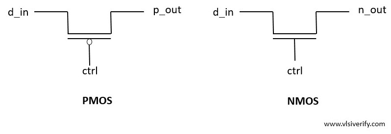
The Switch Level Modeling is used to model digital circuits at the MOS level transistor.
distant raven
I’m not sure I understand what you’re getting at? For it to behave as a transmission gate it would need to conduct both ways but that isn’t necessarily the case.
As for tri-stateable switch, I’m not certain.
Perhaps @cursive sentinel might provide some insight
restive gorge
Ack - the core question in my head is that afaik, nmos transistors won't pass through the full "high" level, it'll reduce by the gate threshold voltage
distant raven
There is a voltage drop across the transistor, yes
But the amount of that is heavily dependent on the gate technology and gate materials
But if we’re considering an ideal nmos transistor, it’s easier to think of the input to output being 1:1
I would generally think it to be fairly negligible in most situations
restive gorge
I'm trying to map this to case being made for using a paired pmos+nmos transistor in https://en.wikipedia.org/wiki/Transmission_gate for instance...
A transmission gate (TG) is an analog gate similar to a relay that can conduct in both directions or block by a control signal with almost any voltage potential. It is a CMOS-based switch, in which PMOS passes a strong 1 but poor 0, and NMOS passes strong 0 but poor 1. Both PMOS and NMOS work simultaneously.
Feel I'm missing something basic, will continue to parse this 🙂
distant raven
Anyway, one thing I should mention is the typical behavior of any mosfet is going to be generalized in two ways. When on, the path between source and drain behaves like a small value resistor allowing it to conduct with relatively little voltage drop, while off they act like diodes (hence why many symbols include a diode between). Obviously losses build as voltage across the source/drain increases.
But I think others here like Herr Brain, madbodger, etc might be able to explain it better
 unique patio
fiery prism
anyone know how to wire up an aditional charging indicator LED to the Feather m0...
unique patio
fiery prism
anyone know how to wire up an aditional charging indicator LED to the Feather m0...
you have to use the same pads that the current LED is connected to. There are no pins available to monitor this. You could remove the existing LED and solder wires that connect to another LED in its place.
You could also make a light pipe that runs from the LED to the outside of your prop, or drill a hole.
cursive sentinel
distant raven
Perhaps <@578805364019953715> might provide some insight
Busy now, but might be available in an hour.
distant raven
Herr Brain has more Herr on their brain in regards to mosfets than I do 🫣
It’s also been ages since I was in vlsi 🥲
restive gorge
No worries, appreciate all ideas. In my hubris, I was trying to simulate some "simple" cmos sequential logic, and realized I was missing a lot of subtlety
 vast flume
Does anyone have experience with probe-rs-cli? I am able to flash a program onto my development board however when I try to run probe-rs-cli debug it fails
 distant raven
vast flume
Does anyone have experience with `probe-rs-cli`? I am able to flash a program on...
distant raven
vast flume
Does anyone have experience with `probe-rs-cli`? I am able to flash a program on...
I’d guess a bad solder joint
Might take some flux and a hot iron and go over all the connections, verify orientation of the physical chip and probe all power points to ensure proper power delivery
vast flume
Its a board I bought not a pcb I made
distant raven
Can you program it in other ways?
vast flume
Yeah thats what I was saying I can flash a program with no issues
Only breaks when I try to debug
 vast flume
distant raven
Is there an update for the probe software?
vast flume
distant raven
Is there an update for the probe software?
I'm on the latest version
distant raven
Hmm. I’m not sure then. You might ask in #help-with-projects
vast flume
Ah actually nevermind I was being a big dumdum
Didn't know I had to specify the chip name when running debug 🤦♂️
distant raven
Ah that makes sense
 frosty scaffold
Anyone have any clue what this is? If I had to guess, it's an 8MHz oscillator, but I have no clue how to find an equivalent part on LCSC.
 unique patio
frosty scaffold
Anyone have any clue what this is? If I had to guess, it's an 8MHz oscillator, b...
unique patio
frosty scaffold
Anyone have any clue what this is? If I had to guess, it's an 8MHz oscillator, b...
it's an 8MHz crystal in a 4-pin package
but you need to know the specs, 8MHz is not the only spec
fiery prism
Thanks for the replies about adding an additional LED charging indicator.
One last question, the LED im adding also is used for the reticle that lights up on my prop. Would it be possible to wire the LED to the LED pads that's already on the board, as well as pin 13 so the LED stays on while it's not charging?
Essentially, I have a reticle that I want to light up with an LED while the board is off and charging, and I also want it to light up while the board is on and NOT charging. If that makes sense
vast flume
You might need a diode to prevent shorting to ground but besides that it sounds fine
I'd go with a shottky diode so you have a lower voltage drop and will have a predictable voltage applied
cursive sentinel
restive gorge
Just a question out of curiosity. According to https://vlsiverify.com/verilog/sw...
I believe the source of confusion here is because Verilog's transistor and switch-level primitives are highly simplified. Keep in mind that as an HDL, [System]Verilog has no notion of current flow, voltage, or electronics in general Verilog-AMS does exist, but is a totally different beast). The five logic levels in Verilog (0, 1, H, L, and Z) are intended primarily for use in simulations, and are poor approximations at the level of individual transistors.
restive gorge
Thanks @cursive sentinel - that probably also explains one of my related confusions about why a transmission gate in verilog was a primitive
frosty scaffold
unique patio
but you need to know the specs, 8MHz is not the only spec
What other critical specs do I need to know?
unique patio
frosty scaffold
What other critical specs do I need to know?
load capacitance and ESR. You can figure out load capacitance by looking at the board schematic. what is this board, and do you ahve the whole schematic?
do you think the crystal is bad? they can fail, but that's pretty rare
fiery prism
fiery prism
Thanks for the replies about adding an additional LED charging indicator.
One ...
anyone have thoughts or ideas on this?
distant raven
fiery prism
anyone have thoughts or ideas on this?
Could you possibly rephrase what you’re trying to do? I’m a little confused by what you’re trying to do
fiery prism
distant raven
Could you possibly rephrase what you’re trying to do? I’m a little confused by w...
im building a prop with a reticle that lights up with a 3 mm LED, i want the LED to light up when the feather m0 express is ON and also while its charging
so i want the LED to be on while the boards on, and while the board is off while it is connected to the charger.
distant raven
I assume you are using the EN pin to control whether the M0 is on/off?
fiery prism
distant raven
I assume you are using the EN pin to control whether the M0 is on/off?
yes i am
 mellow pewter
hopefully in the right area for this.
I'm hooking something up to a 12v battery (ie range is like 11-13.8v ish typical) whats the best way to ensure I always have 12v out? buck boost converter / sepic is what I'm currently looking at. I have some power rails regulated to 1.15/3.3/5.1v using buck/ldo's depending on expected current draw. However I also need ~4 12v outputs approx 3a ish each. Equipment being hooked up is fairly sensitive, so its pretty important to be 12v.
dry pelican
buck-boost will work
supple pollen
mellow pewter
hopefully in the right area for this.
I'm hooking something up to a 12v battery...
These will give 12V regulated at up to 2.5A https://www.pololu.com/product/4984
latent jungle
mellow pewter
hopefully in the right area for this.
I'm hooking something up to a 12v battery...
what are the 4 outputs that require 12 volts?
mellow pewter
latent jungle
what are the 4 outputs that require 12 volts?
Just generic DC jacks Some sensitive some not. Astronomy equipment mainly, cameras, mount, etc
 urban lark
Smoked an EMC2101 pc fan controller last night (not recommended). Assumed I could just use the tachometer input (with shared ground), as the fan is permenantly on and reports speed (not pwm fan). Followed the circuitpython guide. I didn't disable the pull up solder pad on the back (and probably should have), but before I smoke the next one I thought I'd check what's expected in this situation.
 inland jungle
it seems like the MCP2515 is no longer recommended for new designs? Is Adafruit going to jump on the MCP2518FD, CAN FD bandwagon?
 bold salmon
does a Arduino have a precision oscillator output , software controlled ?
 clear matrix
Hello, anyone of you know something about servos?
hushed smelt
clear matrix
Hello, anyone of you know something about servos?
There are plenty of people here familiar with servos, steppers, brushed or brushless motors, motor drivers, etc... though some of it might also be applciable to #help-with-robotics depending on your application of them.
onyx kernel
Im just wondering whats better? I have a 5V input and use 2 LDO's for a 3.3V and 1.8V output. Should i give the 1.8V LDO 5V as input or 3.3V?
clear matrix
hushed smelt
There are plenty of people here familiar with servos, steppers, brushed or brush...
I try with robotics
hushed smelt


This is exactly what I put those bodge pads there. I knew I'd probably get MISO & MOSI backwards. Got the display working with the adapter board though. Success.
Ran a continuity test on every single pin on the board and the pads. Everything checks out except that 1 mistake. So far so good. Haven't started with the touch or sdcard pins yet. You were right Madbodger... wish I made those pads much bigger. It works as a good first prototype board.
hushed smelt
onyx kernel
Im just wondering whats better? I have a 5V input and use 2 LDO's for a 3.3V and...
You always want the least amount of voltage drop possible. Check to see how much drop will be required and then use the closest highest voltage to that. For the 1.8V using the 3.3V input as source sounds more appealing as long as it can supply above 1.8V (plus overhead) it should work.
Going from a 3.3V LDO to 1.8V LDO is probably better than 5V to 1.8V LDO. That voltage has to go somewhere and that's usually heat.
onyx kernel
hushed smelt
You always want the least amount of voltage drop possible. Check to see how muc...
that's what i thought too but wont the overall heat output (of both LDO's) just be the same?
hushed smelt
Yes but it's spread between 2 chips instead of the 1.8V chip taking the brunt of the difference.
those are low voltages, the only way it'll matter for heat is if you have an extremely small PCB like a QT Py. As long as the PCB surface area is large enough the heat dissipation won't be an issue.
 hushed smelt
Is there an antenna on there? Hard to see with missing layers. Just wondering due to the amount of gnd via's around that perimeter. 23mm is fairly small so depending on what else you're stacking on there heat might become a concern.
onyx kernel
in the end the 1.8V are just for the i2C line to the IMC 20948. So the only part needing 1.8V is the level shifter and half the IMC 20948
hushed smelt
The QT Py isn't much bigger and has an ESP32-S3 but whew that QT Py can get pretty darn hot. If you can give it more PCB real estate just for the heat dissipation would be beneficial.
I don't think your design from what I see warrants heat sinks but just something to keep in mind for future designs. You do have to factor in board heating.
onyx kernel
the whole cicuit is off the most time anyways so i think that shouldn't be a problem. The board only powers on when a button gets pressed, a view readings of the IMC 20948 get taken, sent to the base station and the whole thing shuts off again.
supple pollen
onyx kernel
Im just wondering whats better? I have a 5V input and use 2 LDO's for a 3.3V and...
5V is better for servos
hushed smelt
Are there 1.8V servos? That would explain why I melted one. :/
onyx kernel
supple pollen
5V is better for servos
Servos?
supple pollen
onyx kernel
Servos?
Sorry about that, I read your question as if it were a follow-on to a previous question!
onyx kernel
oh i see
 severe star
Anyone know the model or the brand. I'm looking for the data sheet or pinout diagram.

 oblique vale
what is it? a phono jack?
hushed smelt
@severe star What kind of jack is it? Did you remove it from a PCB? If so what PCB or equipment was it in? A single component picture without context is very vague. Could also help with additional pictures from top and side view. There are literally thousands of components that might share that footprint and no one is going to go searching through thousands of components in a database for you without more specific information to match with it.
regal lodge
Not so much help as advice:
Don't always trust the datasheet. I found an error in a TI datasheet. The part is active (as in it's not marked obsolete or not for use in new designs). The datasheet has a date of December 2002. No one noticed (or at least, no one reported) the issue in over 21 years. So... yeah, datasheets can be wrong, so if something isn't working right even though you are following the datasheet, keep in mind it could be the datasheet that's wrong. :3
distant raven
regal lodge
Not so much help as advice:
*Don't always trust the datasheet.* I found an error...
Did you ever check errata? Also which part?
And what was the issue?
regal lodge
errata?
regal lodge
distant raven
And what was the issue?
here, we can make it a game, see if you can find it? XD
https://www.ti.com/lit/ds/symlink/tps2113.pdf
distant raven
Errata is a published error document for parts. You can find them for most parts made by most companies
regal lodge
there isn't one listed in the docs section

regardless, I did report the issue to TI
distant raven
What’s the issue? With the recommended schematic?
regal lodge
don't wanna play the game? lol
distant raven
Nope
regal lodge
it was the description of one of the figures
14
I think
yeah Figure 14
the figure is right, the description is wrong
it should be saying "the VSNS logic signal", not "the EN logic signal"
distant raven
Ah gotcha
regal lodge
the figure even shows a logic symbol on VSNS lol

and the truth table is correct
so I think a real engineer would probably catch the mistake
I know about it because I actually built it but tried to toggle EN, that did not work 😄

I mean it did work in the sense it turns off the output lol
latent jungle
regal lodge
Not so much help as advice:
*Don't always trust the datasheet.* I found an error...
… or always read the entire datasheet. Yes, that’s an error but looking at the block diagram, the pin descriptions, and even the electrical parameters all contradict it.
(Which is probably why it has gone for so long without being corrected.)
 solid gulch
A quick question re: low power sensing. I've got a Adafruit Feather M0 (LoRA) and ideally want to have some sort of sensor it can check in on when it wakes up (light, motion, temp, anything really). The question is, what kinds of sensors can avoid drain while sleeping? Is there a way to use I2C without a constant draw? Thanks!
supple pollen
I2C itself doesn't draw any current when it's idle. It just sits at the supply voltage and no current flows through the pull-up resistors. However, I2C sensors themselves will draw power. However, some motion sensors are basically switches, so you can hook one to a GPIO configured to wake up the MCU. It won't draw any power until it's activated.
solid gulch
supple pollen
I2C itself doesn't draw any current when it's idle. It just sits at the supply ...
Something like PIR triggering an interrupt?
supple pollen
PIR sensors also draw power.
solid gulch
Ah, what sorts of motion sensors don't?
supple pollen
The mechanical ones, like the moving ball sensors like https://www.adafruit.com/product/173, the spring ones like https://www.adafruit.com/product/1766, pressure switches, etc.
solid gulch
supple pollen
The mechanical ones, like the moving ball sensors like <https://www.adafruit.com...
Could I do something like a photocell powered by GPIO only when the device is awake?
supple pollen
Ah, I misunderstood. I thought you wanted a zero power way to wake it up, but you're looking to just have the sensors off when it's sleeping. Yes, you can use various methods to switch power to your sensors so they're not powered when the MCU is sleeping.
solid gulch
supple pollen
Ah, I misunderstood. I thought you wanted a zero power way to wake it up, but y...
Well, either works, however the watchdog sleep on the M0 seems to be like 15 seconds (unless I've misunderstood it), so I can always just check for a change every time it resets and that'll probably be fine.
supple pollen
That seems workable
 sinful valley
Forgive if this isn't the right place to ask;
- I've previously deleted a wire going between two components
- Now when I try to re-connect a wire to the component it doesn't show the wire indicator and doesn't want to connect it
- (Doesn't have a solid line connecting between the components)
- (Also doesn't show the lines connecting the pins in the PCB workspace
I'm pretty new to KiCAD, what am I doing wrong here? Did I screw it up by deleting the wire or something?
I tried restarting it ofc but to no avail, anything else I should try out?
sinful valley
Oh whoops, nvm. Looks like that symbol is just kinda wonky I guess? Not really sure how to fix it though.
 regal dock
I'm looking for an embedded AC power supply to put into my project, I want to be able to plug straight into mains and power a raspbery pi... i've got my eye on this one - is this ok from a safety standpoint to include inside a product housing? or is there a similar product that is more compact?
https://www.digikey.co.uk/en/products/detail/mean-well-usa-inc/RS-15-5/7706168

Digi-Key Electronics
Order today, ships today. RS-15-5 – Enclosed AC DC Converters 1 Output 5V 85 ~ 264 VAC, 120 ~ 370 VDC Input from MEAN WELL USA Inc.. Pricing and Availability on millions of electronic components from Digi-Key Electronics.
unique patio
regal dock
I'm looking for an embedded AC power supply to put into my project, I want to be...
are you powering just the RPi from this? This is equivalent to the 3A 5V "wall warts" that are common for RPi. What is the physical configuration?
You'll need to provide an AC cord, strain relief, maybe some ventilation, prevent access to the mains voltage by poking things into any holes, etc. An external power supply "AC adapter" or wall wart does all that for you. If you don't want it to be USB-C you can probably find one with a round power plug (barrel). Then you just need a corresponding jack
These have barrel plugs instead of USB-C: https://www.digikey.co.uk/short/0h2j84bt
regal dock
unique patio
are you powering just the RPi from this? This is equivalent to the 3A 5V "wall w...
Thanks, yes - I was hoping i could wire parallel into a mains circuit
unique patio
regal dock
Thanks, yes - I was hoping i could wire parallel into a mains circuit
you mean with a power cord? Or is there another mains cord coming into the enclosure?
regal dock
unique patio
you mean with a power cord? Or is there another mains cord coming into the enclo...
not sure if its sketchy but was thinking of looping it off a lighting circuit...?
 rigid plume
Hi folks.
I want an easy to read 5 bar (multi coloured (if possible), red for low, amber for middle, green for full) LED readout with each LED representing approx. 20% of the battery capacity. I want this to be on a discrete PCB which can take the battery’s JST connector. I also want traces of a suitable width and solder pads of a suitable size to allow me to solder to the board and have access to the battery’s voltage for easy use. Our goal is to have something easily integrated into a few projects.
Currently I need it to be mainly analog or just not using MCUs, how would I be able to have a go at this, is there any references for this? Just need a way to read the voltage and display it on the segment LED without an MCU or alot of digital chips
https://uk.farnell.com/kingbright/dc-10ewa/array-10-led-9klv-0-75w/dp/2290323 I'm using this segment display
Thanks
unique patio
regal dock
not sure if its sketchy but was thinking of looping it off a lighting circuit......
I don't understand: is this a permanent installation you are mounting to the wall, or something like that.
unique patio
rigid plume
Currently I need it to be mainly analog or just not using MCUs, how would I be a...
You can buy pre-made battery gauges, like https://www.amazon.com/Jayron-JR-BI005-Battery-Indicator-General/dp/B07KKFV2BZ?th=1
also can buy voltmeters: https://www.adafruit.com/search?q=voltmeter
supple pollen
rigid plume
I want an easy to read 5 bar (multi coloured (if possible), red for low, amber f...
The classic chip for this is an LM3914, which is only available as surplus these days. The AN6884 is a replacement that only drives a few LEDs, but it's a little obscure.
unique patio
The "capacity" calculation varies with the type of battery. Different kinds of batteries have different discharge curves. That's a reason for using a microcontroller and a "battery gauge IC" with multiple settable parameters
supple pollen
If you do use a microcontroller and want to drive a bar graph LED like that, you can do so directly, or with an LED driver like an LP3944
You can, of course, roll your own out of some voltage references (zeners, LM431, resistor divider chains, etc.), along with some comparators.
regal dock
unique patio
I don't understand: is this a permanent installation you are mounting to the wal...
Sorry, yes a temperature sensor on the ceiling... No power outlets nearby but a ceiling light...
unique patio
regal dock
Sorry, yes a temperature sensor on the ceiling... No power outlets nearby but a ...
Then the Meanwell sounds perfectly reasonable. You could have ventilation holes since nobody is going to climb a ladder and stick a paper clip in it to shock themselves. But I don't know anything about electrical codes in the UK, and whether doing this yourself is going to invalidate your fire insurance, for instance.
regal dock
Thanks, I'll look into that . 👍
 split obsidian
I'm re-designing a project of mine, it's got 3.5mm mono jacks as switch ports to an rp2040 based micro. I didn't include any ESD protection, and so far I'm not sure if I need to. Do I need to put TVS or Zener diodes on the board at the 3.5mm mono jacks? These microcontrollers clearly are not breaking and are not being treated special in regards to ESD protection.
cursive sentinel
If you want to be extra careful, I'd recommend something like the BAT54. Otherwise, it's probably fine.
unique patio
split obsidian
I'm re-designing a project of mine, it's got 3.5mm mono jacks as switch ports to...
I really think it has to do with the environment. If you think it might be used in a staticky environment (lots of rugs in winter), then protection is good.
I would note that Adafruit does not typically put protection on pins, including USB lines. We rarely have support q's saying that someone has fried something due to static. I own an expensive third-party piece of equipment where one of the failure modes is fried components that fail in a way that renders the input not usable. In that case, a repair is needed, though the component failure has protected more expensive stuff upstream.
supple pollen
Reminds me of my first computer, which uses 1/4" stereo jacks as serial ports. Then again, the serial driver is a 7400, which is a pretty robust chip, and easy to replace.
split obsidian
@cursive sentinel would an ESD event kill or just be shorted by the bat54? I've seen shottsky diodes but that looks like it's got a third pin
@unique patio what third party piece of equipment are you referencing? I'm a little confused by that.
unique patio
a radio transceiver with a USB port
split obsidian
@supple pollen a lot of accessibility equipment is still interfaced with simple 3.5mm audio jacks
oh gotcha, so it'll basically fry out a fuse instead of let the transceiver be damaged?
unique patio
Something like that. I think the failed component here is an tiny inductor; I don't remember the details
split obsidian
I did this design a while back. But those 3.5mm jacks are just tied to ground and to a gpio with nothing at all between them

I looked at a similar product, and it seems to utilize 4.7kohm resistors between the 3.5mm jack and the GPIO
I'm not sure why there would be a resistor instead of a TVS diode in that product, and it just seems a little superflous. It's running a bare PIC type MCU on a custom board though, not a microcontroller dev board.
unique patio
upon reading about this failure mode again, it appears it was not a component designed to fail in this case. Multiple things failed. Those things did protect some other stuff upstream, but it wasn't a design decision to do that
split obsidian
I mean, I'm not very worried about static murdering this thing, but I'm more concerned why I'm not concerned. Have I been lucky? Or is it just...intrinsically ESD proof enough to handle daily use without me adding more components to my next PCB iteration and I'm trying to complicate things with extra diodes and components I don't understand.
cursive sentinel
split obsidian
<@578805364019953715> would an ESD event kill or just be shorted by the bat54? I...
Oh, I meant the BAT54S. It's a dual schottky diode designed for ESD protection.
unique patio
I think it is true that there is more ESD protection designed into chips these days, but I'm not sure that the typical microcontroller has that.
anyway, my anecdote was less than useful
cursive sentinel
unique patio
I think it is true that there is more ESD protection designed into chips these d...
It's largely a function of the process technology used to build it. Larger nodes tend to have better protection.
split obsidian
do you mean chip like the dev board or chip like the rp2040 @unique patio
unique patio
rp2040
split obsidian
@cursive sentinel how does a bat54s compare to other TVS?
I'm actually not sure how I would wire up a bat54s
cursive sentinel
Haven't looked recently, but for your purposes it will be more than sufficient.
split obsidian
How would I put it in line with the signal line for the gpio
cursive sentinel
 cursive sentinel
Bottom left to GND, middle to the pin you want to protect, bottom right to your power supply.
supple pollen
split obsidian
I looked at a similar product, and it seems to utilize 4.7kohm resistors between...
The resistor is a current limiting resistor, so if a voltage goes into a range where the on-chip protection diodes conduct, the resistor limits the current that flows through the protection diode
split obsidian
@cursive sentinel that might be the thing I do then. That's a pretty cheap way to add ESD protection, and it's a teensy little package that looks pretty easily hand solderable.
cursive sentinel
split obsidian
<@578805364019953715> that might be the thing I do then. That's a pretty cheap w...
Yep, I've even hand soldered the SC-70 variant of it before.
cursive sentinel
vs. SOT-23
split obsidian
is the BAT54s...cathode on pin 2 (the single pin side) and anodes on pin 1 and 3?
supple pollen
Nope. Pin 2 is one cathode and one anode (as shown above)
split obsidian
wait, the pin numbers were off when i said that
pin 3 == cathode and pin 1 and 2 are anodes?
supple pollen
No, it's like the drawing above
split obsidian
idk what I was even saying there.
So how does one make a decision between a high value resistor, a TVS, and a schottsky barrier diode? There seems to be a pennies difference between the three options.
Kind of misread a different datasheet, then came across this one which made it much more clear what's going on.
 cursive sentinel
- High value resistors will cause issues for everything except very slow signals. Rise and fall times will be horrible, and signal integrity will generally be worse. This is especially problematic if you are running through a cable.
- TVS can actually refer to a variety of devices with different benefits and drawbacks. In your case, you would end up using a zener or avalanche diode TVS. The main benefit over the Schottky solution suggested above is that only two connections are needed (between the I/O pin and GND) as opposed to three.
- The Schottky diode approach is very similar to the ESD protection diode arrangement inside your IC, but has the benefit of being larger (able to absorb more energy) and having a lower forward voltage (Schottky diodes incorporate a metal-semiconductor junction, which can't be done on a monolithic silicon die).
@split obsidian either a TVS or schottky pair will work. The one you choose will likely depend on your PCB design. The main downside to the schottky approach is that you need easy access to both your ground and power rails. On a 4 layer board, this is easy. But if you are using only two layers it can get a bit dicey.
split obsidian
I think I'm going to be okay with just the two layer board @cursive sentinel , it's an exceedingly simple design. I'm going to design it out with the recommended bat54s component.
cursive sentinel
Cool
split obsidian
@cursive sentinel Is this looking right?

Switch_1 is a label that will go to an MCU GPIO pin
cursive sentinel
yep
split obsidian
so that's effective ESD protection?
what about the GND line, which would be the sleeve of the audiojack?
Do you need to ESD protect a GND line?
split obsidian
Would I need a second bat54s for the GND line of the connector?
cursive sentinel
Nope. That's why you are using the BAT54S in the first place. It clamps negative voltages to ground and positive to your supply.
It is worth noting, however, that ESD would not be my biggest concern here.
The bigger question here is what happens during the time you are plugging the cable in? As the tip enters, it will make contact with the ring, shorting whatever is connected at the other end of the cable to ground.
split obsidian
@cursive sentinel the other end of the cable is only ever going to be a button, something like a cherry MX or a microswitch of some kind.
like 99% certain it's always going to be normally open at that, 1% chance it'll be normally closed....but...yeah...that's it for variation
for now.
One day I'll need to design in a 3.5mm jack that's not mono and is a TRRS that will be connected to two potentiometers...(that's wire compatible to the xbox adaptive controller's joystick ports) but that's about it
I don't understand why that's "the bigger question" and I just...don't understand I'm not being snarky about it...What did you mean by that?
cursive sentinel
Alright, that's fine. Although you will likely register false presses if you plug/unplug the connector.
split obsidian
I'm 100% willing to be okay with that
what I'm mostly worried about is a switch that gets touched and zapped and then carries to the plug
over the wire
cursive sentinel
split obsidian
I don't understand why that's "the bigger question" and I just...don't understan...
I didn't know what exactly you were planning to connect to it. For example, it would have been problematic if one of the contacts was connected to your power supply.
split obsidian
oh, it's 100% just going to be like...xbox adaptive controller buttons/switches
there's a switch kit from logitech
but I'm designing my own switches/joysticks and such
the thing is I'm not using the XAC, I'm making my own device that emulates various HID functions
*again. I made it before, but it didn't have any ESD protection. I'm really doing a redesign so it's entirely SMT parts
cursive sentinel
Ah, I see. BAT54S is more than enough then.
split obsidian
and just on the tip and not the sleeve?
(sleeve is GND)
@cursive sentinel do you think the BAT54S is even necessary or just superflous overkill?
cursive sentinel
Well, it certainly won't hurt.
unique patio
@split obsidian if this is for adaptive hardware, I'd say make it as bulletproof as possible, since people really depend on it and getting it replaced or fixed may be difficult.
split obsidian
It is! I'm trying to make it as bulletproof as possible.
rigid plume
supple pollen
The classic chip for this is an LM3914, which is only available as surplus these...
Thanks, I made a solution I followed from another different project - what do you think
 cursive sentinel

Joking aside, I think the BAT54S will be fine for this.
And if you want to be absolutely sure, get an ESD compliance officer.
They can be obtained for free from your local animal shelter.
 knotty tiger
is that a calibrated ESD source there?
cursive sentinel
CATlibrated
They are very good at spot checks, since they tend to sort of just walk in and lay on your desk.
supple pollen
rigid plume
Thanks, I made a solution I followed from another different project - what do yo...
No, the LM339 is an open collector output, it doesn't pull up, it only pulls down. So you'd connect the other anodes of the LEDs to voltage and the cathodes to the LM339
regal lodge
is this crystal placement ok? :3
 distant raven
regal lodge
is this crystal placement ok? :3
distant raven
regal lodge
is this crystal placement ok? :3
I’m weary of this because crystals more often than not need two load capacitors
Unless it’s an oscillator with built in load capacitors
regal lodge
the data sheet for the IC said not needed
cursive sentinel
For the IC or the crystal? The crystal datasheet takes priority here.
 cursive sentinel
Hmm interesting.
Don't know why they thought it would be a good idea to integrate those into the chip though. Ultimately it just ends up restricting oscillator options.
regal lodge
Adafruit also did not use crystals for it :3


Never hunt around for another crystal again, with the Si5351A clock generator breakout from Adafruit! This chip has a precision 25MHz crystal reference and internal PLL and dividers so it ...
I went with NX3225GA-25.000M-STD-CRG-2
cursive sentinel
Ah, that's a more specialized chip, so it makes sense.
 regal lodge
is this crystal placement ok? :3
regal lodge
regal lodge
is this crystal placement ok? :3
^ I was more concerned with the crystal's placement near the voltage regulator
though it is an LDO not a switching regulator so probably not bad?
cursive sentinel
That entire board is basically a patch antenna, so...
regal lodge
?
cursive sentinel
If you're worried about EMI, I'd be more concerned about the size of the board than the placement of the LDO. Regardless, I doubt it'd be a major issue here.
regal lodge
it is a 4-layer board
cursive sentinel
That might help
regal lodge
I put the row of vias to try to help too
regal lodge
I may have went overkill on the ground vias

power plane (outside edges = ground)

ground plane

top layer
 urban lark
is there a cheap chip that can do battery polarity switching, instead of reverse polarity protection?
in other words, I want the chip to take the battery power, and only connect internally once sure which is which line is which (some low-R fets?), presumably with the ground-OUT floating a little differently to battery-ground, and similarly losing a smidge on VBAT-OUT compared to true battery voltage. I guess in an ideal world it would charge too, and then i suppose it would need to take in VCC aka VUSB, and output the higher of VUSB vs VBAT-OUT, or could even do boost of vbat to 5v if you want to talk the "ideal" chip.
Long story short I don't want to worry about polarity and don't want to loose too much voltage from vbat so probably need to think boost toplogy, but wondered if I could do without. Then the thought of charging the battery occurred to me, and I realise it's basically a charge/discharge chip with boost and instead of reverse polarity protection it works with battery polarity both ways.
supple pollen
urban lark
is there a cheap chip that can do battery polarity switching, instead of reverse...
I'm not sure what your definition of "cheap" might be, but there are chips like the LT4320 that might be what you're looking for.
 coarse lark
yo
why is the ATSAMD21E18 so expensive
nevermind, ill look into other models
wait why is the G18 expensive as well
~$6
whoahoahoa cheapest shipping option for chile is 100 dollars
cheapest G18 i found that ships to here is $6 on ali
is it just me or is it a bit too much for a single chip?
urban lark
supple pollen
I'm not sure what your definition of "cheap" might be, but there are chips like ...
Thanks! Ideally <5$ singles, or <2$ in hundreds. I'd pay more for single chip ideal diodes + buck/boost/LDO or just BMS charger/fuel gauge. Just want 5V from anything+everything DC or battery related & USB. Tricky bit seems to be wanting variable battery chemistry (LiFePo4 ideally, but support older tech too) as well as the moon on a stick for under 10$.
supple pollen
Variable battery chemistry isn't a problem if you're not concerned with charging
tough matrix
coarse lark
cheapest G18 i found that ships to here is $6 on ali
it is. I'd say $3 is good, $4 acceptable, more than that is unreasonable.
In US, digikey has it for $4.25
https://www.digikey.com/en/products/detail/microchip-technology/atsamd21g18a-aut/4878867

Digi-Key Electronics
Order today, ships today. ATSAMD21G18A-AUT – ARM® Cortex®-M0+ SAM D21G, Functional Safety (FuSa) Microcontroller IC 32-Bit Single-Core 48MHz 256KB (256K x 8) FLASH 48-TQFP (7x7) from Microchip Technology. Pricing and Availability on millions of electronic components from Digi-Key Electronics.
coarse lark
tough matrix
it is. I'd say $3 is good, $4 acceptable, more than that is unreasonable.
In US...
thats not a problem
this is the problem

the shipping is INSANITY for a little 4 dollar chip
then again i did find a retailer on aliexpress that has it for 6 dollars with shipping
 faint haven
I am trying to make an LED stick that uses a mix of RGB leds and Cree leds to get the most power for a sort of headlight. The overall dimensions of the board is 150mm x 8.5mm and I wanted to control the stick with some sort of standard RGB,RGBW,etc. protocol so that the final pcb can be easily used anywhere. So far, I was planning on making a board like this:

The issue I am running into is figuring out a way to make it so that when the RGB leds are off, the white Cree led's turn on or use RGBW and an external TM1814 IC to turn on the Cree leds (which wouldn't work because then the data would get messed up as the SK6812 Mini's are only RGB)
The only idea I have come up with so far is to just use a bunch of TM1814 IC's to control each "dumb" RGB led and then the white channel of one of the IC's goes to a PMOS with a pull-up resistor to turn on all of the Cree leds. This solution would technically work, but would be a bit bulky with all of the IC's
The overall cheapest solution would be to make it a 4pin input connector where one pin just turns on the Cree LEDS directly with a mosfet and then that way the SK6182's could just run indendently, but then it wouldn't be just a plug and play solution
faint haven
Something that I am trying to do that I think would solve this issue is to split the DIN pin with one end going to the SK6812's and another wire that goes to a logic inverter. This way we wouldn't have to make the Cree's LED0 but rather smooth the input signal such that if the signal if above 0v then the Cree's turn off. If anyone has an idea of how to do this I would really appreciate it
 willow tartan
Hey guys,
I created this pcb and I am trying to make the mcu to at least make a beep(or ding) when I connect the usb to pc but it doesn't do anything (checked every pin on the mcu and it as a 0.5~ voltage drop on all pins except the crystals oscillator pins). I tried with Boot0 to high when I connect to pc but 0 success. What can be the issue (i know it is possible to be de design itself, took it from a reference design with a similar stm32u5 mcu)?
 willow tartan
 distant raven
willow tartan
Hey guys,
I created this pcb and I am trying to make the mcu to at least make a ...
distant raven
willow tartan
Hey guys,
I created this pcb and I am trying to make the mcu to at least make a ...
Only thing that looks odd to me at a quick glance is you are powering reset with 3.3V rather than using a pull up resistor which is usually standard practice. I’m not familiar enough with stm32 recommendations to know if they recommend a pull up. But I’d suspect that the MCU has a hard time pulling reset low at start up which would probably cause issues.
Fascinating, they use an internal pull up on reset.
If you have an oscilloscope you can probe the crystals to see if they are generating their states frequency.
That will tell you if the MCU core is starting up properly
cursive sentinel
distant raven
If you have an oscilloscope you can probe the crystals to see if they are genera...
Keep in mind though that the probe will easily have enough capacitance to interfere with the crystal.
distant raven
cursive sentinel
Keep in mind though that the probe will *easily* have enough capacitance to inte...
I’ve probed a 12MHz crystal just fine. As long as it’s within a reasonable margin of error
cursive sentinel
Yeah
distant raven
I’m thinking mostly seeing if the MCU core is getting far enough along to get past its internal oscillator and startup
Which should rule out any issues with power delivery
 gloomy lion
Curious if anyone's tried this before, or if it's a terrible idea - I'm working on a little custom board with an RP2040 and ESP32, and if possible I'd like to share a single USB C port between the two. I was thinking it would be cool if I could toggle which is connected through a DIP switch or something. Is there an ideal way to do this kind of thing? Just routing D+/D- through different poles of the switch probably wouldn't be the best for signal integrity, lol
gloomy lion
I'm actually thinking it might be easier and just as functional to throw a 2-port USB hub on there tbh
unique patio
gloomy lion
Curious if anyone's tried this before, or if it's a terrible idea - I'm working ...

The Adafruit TS3USB30 1 to 2 USB Switch is a nifty breakout board for the TI TS3USB30 that will let you connect one of two USB devices to a single port, handy when you have multiple chips ...
gloomy lion
lol of course you guys already have something for that, thank you again!
hushed smelt
@gloomy garden If you want to learn PCB design this is the best channel to ask your questions. I use EasyEDA for PCB design. It's free and there is a learning curve to using the program but it's worth learning. There are many design programs that others here can recommend, I only have experience with that one.
 gloomy garden
Thanks @hushed smelt, appreciate the info. What service do you use to produce your PCBs?
hushed smelt
JLCPCB but PCBWay is comparable. There are also many US based services like OSHPark and CyberCityCircuits. EasyEDA ties into JLCPCB so ordering is just easier with them instead of exporting and converting gerber files to something another service can use.
gloomy garden
Got it, thanks! I will check them out. Appreciate the info.
fervent lance
Easyeda is actually a pain, it's a lot of manual work. There are not batch solutions
With kicad there are lots that make it more compatible with jlc
Kicad along with other edas are not that better, but better than nothing
tough matrix
I actually quite like KiCad.
and it does have a plugin to make ordering from jlcpcb very easy
gloomy lion
Kind of struggling to figure out how I should connect this ESP32 to the RP2040 for use with the ESP32SPI library/NINA firmware - I'm specifically planning to use an ESP32-C6-WROOM-1 module and the naming convention for the pins is throwing me for a loop, haha
I assume I'm meant to use the FSPI pins, but FSPIHD, FSPIWP, and FSPID are all new to me. Not sure which is RX/TX and so on. CS is pretty obvious but there are like 6 CS pins and I'm not sure if there's a specific one I should be using
distant raven
gloomy lion
I assume I'm meant to use the FSPI pins, but FSPIHD, FSPIWP, and FSPID are all n...
Nope, FSPI for SPI Flash. SPI is going to be using the SPI peripheral which in general should be configurable on any pins listed as supporting it
gloomy lion
oh awesome, that makes sense! thanks for clarifying
this is my first time working with the ESP32 in any capacity and my google skills are failing me today
distant raven
You’re gonna use pins specified as SPI2, see section 3.4.2 of the data sheet 🙂
Okay, so it doesn’t list specific pins that are connected to SPI2, but on other ESP32 you can generally use any GPIO that is no the IOMUX for SPI
gloomy lion
fantastic! thank you again, I'll take a closer look at the datasheet either way, but I'm sure the pins I should use are defined in the NINA firmware somewhere
distant raven
 gloomy lion
awesome, thanks!
gloomy lion
oh, just to be sure since it's been a while, are the pins defined in the C++ sketch by raw pin number, or GPIO number? like, would SPISClass SPIS(VSPI_HOST, 1, 14, 23, 18, 5, 33); use, say, pin 33/GPIO 21? or pin 9/GPIO 33?
distant raven
gloomy lion
oh, just to be sure since it's been a while, are the pins defined in the C++ ske...
That’s a good question, I’m not sure. I would think that for Arduino, it should match whatever the actual pin number is. For the ESP IDF, I believe there is a pins.c file which has pin definitions in it.
gloomy lion
Cool, I'll check there - thanks!
distant raven
gloomy lion
So it looks like it's the GPIO # and not the raw pin number, nice
gonna have to recompile the firmware myself either way tho because it looks like the default configuration uses GPIO 14 for SPI TX, which isn't broken out on the board I plan on using haha
oblique vale
unique patio
https://www.adafruit.com/product/5871
that's a cool board. I wish Adafruit had a 4-port multi-TT USB2 hub breakout on a tiny board like that. tiny hub breakouts seem uncommon, and they're nearly always single-TT.
hollow cosmos
On the Adafruit website, it says “These are the inputs to the motor control. IN2 goes to OUT2, IN1 goes to OUT1.” Not only does imply that TWO motors can be connected to the board (OUT1 and OUT2), but there is no OUT2 — that’s where the power IN terminal block goes. And the data sheet says the logic that goes to IN1 and IN2 is actually quite complex: hold IN1 high while you PWM IN2 to adjust the forward speed, and hold IN2 high while you PWM IN1 to adjust the backward speed, except that holding both IN1 and IN2 high means to “coast” the motor.
QUESTIONs: what does that simple statement on the website mean, anyway? (https://learn.adafruit.com/adafruit-drv8871-brushed-dc-motor-driver-breakout/pinouts). What do “1” and “2” mean, as printed on the board? This is all very confusing, and I think I want to send the part back now.
supple pollen
hollow cosmos
On the Adafruit website, it says “These are the inputs to the motor control. IN2...
OUT1 and OUT2 are the two pins on the motor connector.
The normal connection is a single motor from OUT1 to OUT2. However, you could have a motor connected between one of the power supply leads and one of the OUT leads. That would let you control the speed in a single direction. If you want to run the motor in both directions, it would need to be connected from OUT1 to OUT2.
restive gorge
(just idle curiosity and laziness from playing electronics over the long weekend 🙂 does SPI in practice for most devices have an actual minimum clock speed, or is it feasible to "manually" toggle switches to talk to most of them? (I realized a bit too late that the I2C devices I had at hand were also implementing the smbus protocol, so my attempts to flail at buttons wired to them failed.)
supple pollen
I suspect some devices would work at manual speeds, but some probably don't. Note that you'd have to use a debounced switch for at least the clock signal
tough matrix
hollow cosmos
On the Adafruit website, it says “These are the inputs to the motor control. IN2...
to add to madbodger's answer, "1" printed on the board is short for "OUT 1" and "2" stands for "OUT2".
As for complex logic, yes, it is slightly confusing, but this is the common way of controlling DC motors.
and there is a diagram that clearly shows how you connect a motor: https://learn.adafruit.com/adafruit-drv8871-brushed-dc-motor-driver-breakout/usage
fiery prism
would anybody be able to help me review a PCB i designed on EASY EDA
hushed smelt
fiery prism
would anybody be able to help me review a PCB i designed on EASY EDA
Depends on how advanced the design is. I can probably review beginner level designs.
You can share your projects via OSHWlab. It's integrated into EasyEDA.
fiery prism
hushed smelt
You can share your projects via OSHWlab. It's integrated into EasyEDA.
perfect yeah i had a friend do it on easy eda
fiery prism
hushed smelt
Depends on how advanced the design is. I can probably review beginner level des...
all i have from him is the .json file could i send you that?
hushed smelt
i don't think a json file could be analyzed in easyeda.
hushed smelt
oops, nvm. apparently an exported easyeda file is in fact json
fiery prism
hushed smelt
shows you how often i export backups. :/
fiery prism
heres the .json... its sucha messs
hushed smelt
looks like glasses. as long as the LED's are routed correctly should be quite simple with neopixels.
i'm not seeing any copper fills for top and bottom layer
without the schematic will be hard to check for correct nets and drc
oh it's using gnd traces instead of gnd planes. that's probably not a great idea with some of the traces being so close together without a gnd fill between them.
there is a minimum clearance of 6mm according to the design rules which can be inspected/changed in Design>Design Rule.
woven bluff
Chinese fabs charge an arm and leg for castellated holes, any workaround?
perhaps make regular PTH and cut it yourself?
hushed smelt
Lady Ada uses a workaround where the board outline intersects large vias. just make a big via and cut it in half basically.
Using copper fill will allow you to go straight to ground. Since all GND traces are just one web of a net you can completely bypass it by creating a single gnd plane and using vias to gnd.

that will cut out a considerable amount of traces and potential crosstalk.
since it's not a diode matrix you can use gnd planes no problem.
when you see blank areas use a gnd via and it will fill it in with copper.

Something like this is not optimal as two traces are next to each other without a copper fill in between to prevent crosstalk.

This is a little better but I left the two traces close enough where you can see the copper fill can't get past the clearance between the traces. This is set by the clearance design rule.

now it's fixed and will pass DRC. this is just 1 example of an improvement that can be made. to fix all of it across the entire board would take some time but the time saved by using gnd planes instead of gnd traces would be pretty big.

It might not be possible in all situations to put copper between two traces. You do what can to prevent crosstalk or RF interference.
woven bluff
hushed smelt
Lady Ada uses a workaround where the board outline intersects large vias. jus...
That's what I did when creating normal castellated holes, but I also added castellated hole attribute in the board setup. Wouldn't the fab object when they find you cutting through via without setting the castellated hole attribute?
fiery prism
hushed smelt
It might not be possible in all situations to put copper between two traces. You...
thanks for diving into that... i found a work around for those holes and will no longer need them
however i want to also decide if i have the correct capacitor
im using this WS2812B^
the translation to english is difficult to understand
theres two schematics on this data sheet that say 104 under the capacitor but idk what that means


what capacitors are used on the neopixel strips?
oblique vale
104 probably means 0.1uF?
https://circuitspedia.com/how-to-read-ceramic-capacitor-code-value-104-chart/
fiery prism
interesting... so what does this chart explain exactly when it talks about the WS2812B capacitance?
 oblique vale
dunno ¯_(ツ)_/¯
hushed smelt
The number "104" on a ceramic capacitor is a code that represents the capacitance value. In this case, "104" stands for 10 followed by four zeros, which is equivalent to 100,000 picofarads (pF) or 0.1 microfarads (uF) or 100 nanofarads (nF).
The amount of power fluctuation expected with a neopixel is extremely small. They have the controller chip built into the LED. Each LED only requires a very tiny capacitor, and some don't require a capacitor at all. Input capacitance is the same thing, power smoothing on the input.
When using circuit design references it's best to use one designed specifically for the exact LED you're using. It should be in the LED datasheet.
Here's a similar neopixel schematic I created based on the manufacturer reference design in their datasheet.

and the board layout. by using a GND plane each GND out pin goes straight to a via. this allows for very compact design. you can make it even more compact by putting the capacitor on the other side of the board, however a 2 sided smt service costs more than 1 sided. 😉


and everything turned out better than I expected because i followed the reference design. this was the first board i ever had smt assembled and it worked the first time. neopixel boards are an excellent project.
 gloomy lion
Is it a silly idea to include 2 separate voltage regulators on a board for powering separate microcontrollers? Right now I have an XC6206 supplying power to the RP2040 and a beefier AMS1117 powering the ESP32 since it draws a lot more current than the XC6206 can supply
If that's all fine, I also want to double check whether I should be connecting the 3.3V lines between the two - I'd assume yes, but just wanna be sure
 limpid nest
Did I wire this right? https://www.digikey.com/en/products/detail/omron-electronics-inc-emc-div/EE-SX1088-W11/5864616


Digi-Key Electronics
Order today, ships today. EE-SX1088-W11 – Optical Sensor Through-Beam 0.134" (3.4mm) Phototransistor Module, Wire Leads, Slot Type from Omron Electronics Inc-EMC Div. Pricing and Availability on millions of electronic components from Digi-Key Electronics.
hollow cosmos
What cheap connector can be used with the t-slot interrupter (EE-SX672) that Adafruit sells? Should I solder on the wires?
 sick violet
Does this form factor have a name? It seems common to industrial control systems maybe?
 distant raven
sick violet
Does this form factor have a name? It seems common to industrial control systems...
distant raven
sick violet
Does this form factor have a name? It seems common to industrial control systems...
The height is probably 1U. As for the other parts of the form factor, not sure. Might be like a 1U snap in module?
Can’t really find anything like that.. I’ll dig some more
limpid nest
distant raven
The height is probably 1U. As for the other parts of the form factor, not sure. ...
Mind weighing in on my question? I feel like I'm missing something obvious. I did include a pull down fwiw
dry pelican
fiery prism
Equivalent capacitance on data input
distant raven
limpid nest
Did I wire this right? https://www.digikey.com/en/products/detail/omron-electron...
 distant raven
Not quite
distant raven
I’d have a resistor between the phototransistor and ground
limpid nest
RL? Sorry I forgot to include that in my drawing. I have one
When the sensor is not plugged in the "emitter" reads 0v, when plugged in, the emitter reads .3V irrespective of whether something is blocking the sensor.
distant raven
Hmm 🤔 that is interesting
sick violet
distant raven
The height is probably 1U. As for the other parts of the form factor, not sure. ...
Might be 1/32 DIN.
What Are The Standard DIN Sizes of Panel Mounted DIN Temperature Controllers? There are four main standard DIN sizes. Panel mounted temperature controllers require a hole to be cut out of the panel in order to house the device. Therefore the standard DIN sizes enable equipment manufacturers to identify panel space required.
Ugh, everything seems to want to give BEZEL dimensions. Not helpful.
 fiery prism
hushed smelt
and the board layout. by using a GND plane each GND out pin goes straight to a ...
fiery prism
hushed smelt
and the board layout. by using a GND plane each GND out pin goes straight to a ...
would it be best to have a GND layer and a VDD layer?
also, if im designing my schematic, can i just design it in one strip or do i have to do it in the shape of this image?
 fiery prism
hushed smelt
Here's a similar neopixel schematic I created based on the manufacturer referenc...
fiery prism
hushed smelt
Here's a similar neopixel schematic I created based on the manufacturer referenc...
would i be able to just put 57 leds in a row like how you did here? and then i can arange them on the PCB?
hushed smelt
fiery prism
would i be able to just put 57 leds in a row like how you did here? and then i c...
Yes, you can split them into groups in software (code). You don't need separate physical chains/groups if they're addressable LED's. The Neopixel library has a grid mapping function that you'll find useful.
fiery prism
hushed smelt
Here's a similar neopixel schematic I created based on the manufacturer referenc...
Okay just to confirm, for my schematic can I get away with having the layout similar to this but a row of 57 LEDs?
hushed smelt
Sorry was occupied with another conversation for a bit. Connecting them on the PCB is very similar to doing it with physical strips. Just connect them all in 1 row.
Can you use an entire plane for VDD? Yes but usually that's with a 4 layer board and VDD would be sandwiched in the middle somewhere. 2 layer is best to stick with GND plane on top and bottom and route your VDD, DIN, DOUT traces.
Any GND's from the LED's can go straight into a GND via that connects directly to GND plane. Having the GND planes will eliminate the need for any GND traces.
hushed smelt
fiery prism
Okay just to confirm, for my schematic can I get away with having the layout sim...
Yes
Make sure that your VDD traces are a little thicker than the other traces. That's your power bus and will need enough trace width to feed all the hungry hungry hippo LED's on the board.
Also when you're ready to send it to fabrication you can elect for a "production review" where an engineer will take a quick look at your board and if there are any really obvious issues they'll offer advice. Make sure you don't pay in advance and elect to "pay after review". The review is only like $5 more, worth it. They caught an issue in one of my designs once and I was quite happy with their advice. It did mean refunding the order, redesigning and resubmitting a new order. Worth it though.
fiery prism
So for my GND planes do I need two? On top and bottom? Why don't I just need one?
hushed smelt
Preferable one on top and bottom yes. It allows you to more easily fill in any missing gaps using GND vias. The VIA's connect one GND plane to the other. 😉 You can route on both sides of the board that way too allowing for twice the PCB build area.
fiery prism
hushed smelt
Preferable one on top and bottom yes. It allows you to more easily fill in any ...
Gotcha so how many layers should my board be if I'm just doing the WS2812b and caps?
hushed smelt
Here's what my top and bottom layers look like. You can also use VIA's to jump over traces to get them to the other side of a trace, something you'll eventually learn how to do with more compressed designs. You can't jump traces with a single layer board. I mean you can do single layer there's nothing wrong with that. I simply find 2 layers the easiest no matter the situation or how big the board is.


 hushed smelt
and here’s the board. Just arrived yesterday.
 hushed smelt
fiery prism
Is that Easy eda?
hushed smelt
fiery prism
Is that Easy eda?
Yes
hushed smelt
Just 5. Was $26.63 USD total to my door. That makes it about $5.30 USD per board. Shipping cost depends on where you live though. It was $6.60 for the PCB's without shipping, so shipping was about $20 USD and most of the cost. I submitted the order on the 14th and they were here by the 20th which means they must have a fabrication plant in the US now. Previous orders took over a month sometimes.
Here's what my workspace looks like, same as any EasyEDA user.
 fiery prism
Wow that's awesome. Super cheap and definitely beats having to solder strips for 4 hours 😭
Thank you so much for all the info imma try to tackle this on my own, but just curious, do you accept commissions? If I wanted you to design it for me.
hushed smelt
Just consider that your breadboard prototype. It always helps to prototype before making a PCB. You can design a PCB without prototyping... YOLO and send it. You'll end up with a lot of coasters that way, I don't recommend it.
I've never designed a PCB for someone else before. I'd be pretty hesitant. I still consider myself a beginner. :/ It's better if you learn to do it yourself... life skill.
fiery prism
I agree it is a good skill to have
limpid nest
distant raven
Hmm 🤔 that is interesting
Figure it out btw. For some reason I added a 100 ohm in parallel with my pull down. No idea why but I did. I ended up populating it by rote.
Thanks for your help.
 terse zodiac
If i connect a adafruit sound fx board (https://www.adafruit.com/product/2220) and control via TX/RX is there a limit on how many audio files I can play?

Would you like to add audio/sound effects to your next project, without an Arduino+Shield? Or maybe you don't even know how to use microcontrollers, you just want to make a sound play ...
hushed smelt
terse zodiac
If i connect a adafruit sound fx board (https://www.adafruit.com/product/2220) a...
With what language Arduino or Circuit Python? This doesn't seem like a hardware design related question on the surface.
terse zodiac
arduino
hushed smelt
Recommend you ask that question in #help-with-arduino as it seems like a software based question.
terse zodiac
ok thank you
restive gorge
(in the just for fun and learning category) I was playing if just a simple capacitor works as a dodgy "dynamic" 1-bit memory on a breadboard. Outside of things like accidentally grounding the cap/etc, they seem to hold state for a several minutes at least. Is this something that's so obvious it needs no discussion? 🙂 (every thing I read around memory seems to start out with cross-connected logic gates; and this one (at least in my head) seems easier to understand how it behaves...) http://tinyurl.com/24u6ym2f
hushed smelt
Depends on the type of capacitor. Some can hold a charge for a very long time as long as there is no load on it. The act of measuring the capacitor is what will put a load on it and drain it.
 lost tusk
The IBM 650 is an example of an early commercial computer that used capacitors for register memory. Going earlier, the ABC (Atanasoff–Berry computer) used capacitors mounted on a revolving drum for memory.
restive gorge
Ha! gtk this idea was used as far back as that, nice.
hushed smelt
I think of capacitors like small batteries.
lost tusk
Another fascinating early memory device is the Williams-Kilburn tube. Used in experimental and early commercial computers, information was stored on the face plate of an oscilloscope tube. See https://www.computerhistory.org/revolution/memory-storage/8/308.
restive gorge
ingenious 🙂 must have been fun to watch, though I guess there must be some sensor covering the tube to be able to read the charge dots, so maybe it's not actually visuble...
lost tusk
restive gorge
ingenious 🙂 must have been fun to watch, though I guess there must be some sens...
They used a copper wire mesh, so you could see the spots change as the computer operated. When IBM held a demonstration of their new 701 mainframe they had to cover the tubes with sheets of paper. Reporter's flash bulbs were "disturbing" the memory and crashing the demo.
restive gorge
Ah, wow - really cool! Been reading up on the wikipedia article on it. Fascinating - thx for the interesting pointer 🙂
Found a cool snippet of it in action here: https://youtu.be/SpqayTc_Gcw?t=65 - fun!
lost tusk
Electrostatic memory proved to be problematic. One of the chronic difficulties affecting the IBM 701 was the "Navajo Blanket" bug where the machine would crash with the tubes displaying horizontal bars. A Herculean debug effort identified the root cause as intermittent leakage in the counter-wound precision resisters used to position the electron beam, but by then cheaper and more reliable magnetic core memory was available. IBM quickly replaced all of the electrostatic memories in the field with core.
 oak oriole
And the next memory revolution is happening right now: MRAM ist about to replace flash.
restive gorge
Very cool @lost tusk - lot of clever ideas, notwithstanding.
distant raven
oak oriole
And the next memory revolution is happening right now: MRAM ist about to replace...
You should specify that it’s STT-MRAM which is a little different than normal MRAM (at least what I can see from a quick bit of reading)
Which STT-MRAM is pretty nifty. They are planning to replace SRAM, DRAM, and NOR-flash
Nothing about NAND flash though
Looks like replacing NAND flash will take longer
supple pollen
restive gorge
(in the just for fun and learning category) I was playing if just a simple capac...
That's the different between static RAM and dynamic RAM. Static RAM uses flip-flops that can hold their state indefinitely as long as they're powered. Dynamic RAM uses capacitors to hold a value briefly, but it has to be "refreshed" periodically before the charge leaks away. Since a capacitor is smaller and simpler than a flip-flop, dynamic RAM is popular for large capacities.
I'm actually tempted to try to build a Williams tube memory
fiery prism
can someone tell me if this is an error?


on Easy EDA the WS2812b has this pinout, but on the data sheet its flopped around.
the compononent i selected is from the manufacturer

even on this diagram on the same data sheet, the notch on the component flops from GND to VSS
split obsidian
Question, why does pin 3, the IN line, have a 0.1uf cap and a 47k resistor? I don't understand the analog circuitry there and would love a brief explanation of the logic behind the inclusion of those components!

I see a section in the datasheet https://www.mouser.com/datasheet/2/115/PAM8301-247302.pdf concerning the "input capacitors", it reads like total jargon to me...it also doesn't reference the resistor?
cursive sentinel
The cap looks like it's just there for AC coupling. Without knowing the input impedance of the amp though it's hard to say why they are using a 47k resistor specifically.
supple pollen
It could be to adjust the RC time constant, and therefore the corner frequency
restive gorge
I could be wrong, but looking at the datasheet; might it also affect the gain of the amp? It seems like the 47k resistor would be in series with R_i. The gain would be reduced.
lost tusk
supple pollen
I'm actually tempted to try to build a Williams tube memory
I think that's a great idea for a project. Here are technical docs (including schematics) for IBM's 706 electrostatic memory: https://ed-thelen.org/comp-hist/IBM706-WilliamsTubeMemory-RandyNeff.pdf.
 pale lark
Is this a good place to ask about identifying a specific connector?
Looking to identify this connector labelled i2c.

Here is a photo of the pcb without the socket:
 restive gorge
(not an expert) but it looks like a jst connector right? Maybe an EH, but not sure.
tough matrix
pale lark
Is this a good place to ask about identifying a specific connector?
from the photo it seems that the pins are rounds, not square - is it indeed so?
if so, it is a very unusual connector, certainly not JST PH/EH/GH
pale lark
tough matrix
from the photo it seems that the pins are rounds, not square - is it indeed so?
...
Cable end has round holes.
supple pollen
Molex makes some connectors like that, but I don't recognize that particular variant.
gloomy lion
Anyone got tips/tricks/go-to resources for PCB routing? I can never help but feel like my routing could use work, and that I should've started somewhere else when I inevitably leave too little room for a component down the line
cursive sentinel
gloomy lion
Anyone got tips/tricks/go-to resources for PCB routing? I can never help but fee...
My main piece of advice is "focus on component placement."
PCB Layout Guide
- Start by placing mounting holes, connectors, switches, and anything else with mechanical constraints. If it can't be moved, place it.
- Place components that need good signal integrity (this usually isn't a concern for hobbyist designs). This is also a good time to place decoupling and bypass capacitors.
- Place components with the most external connections.
- Place power and other support components.
- Begin routing according to net priority. If there are any analog or high-speed digital paths, start with those. After that, make local connections (decoupling caps to IC pins, crystal oscillators, etc). Then power. Then low speed digital such as I2C and switches/buttons.
gloomy lion
Gotcha! That makes a lot of sense
I've been trying to do that but I struggle a lot with doing so while also making the design look nice
Here's an example - lizard brain says to route as much as possible on one layer no matter what lol, it's hard to fight


Feels like I've got too many vias
cursive sentinel
For a two-layer board, you want to use the back as a ground plane, and minimize traces there.
But if you need a via, you need a via. It's not something to worry about unless you are dealing with gigabit stuff.
Also, unless you are planning to hand-solder it, those holes under the QFN package look too big.
gloomy lion
cursive sentinel
For a two-layer board, you want to use the back as a ground plane, and minimize ...
Makes sense! I'm only doing the opposite right now because it's easier for me personally to visualize the final board the way I'll be using it, instead of trying to mirror it in my head (visual stuff on the front, screen etc, most of the vital components on the back)
gloomy lion
cursive sentinel
Also, unless you are planning to hand-solder it, those holes under the QFN packa...
Using JLC's assembly service for this one. I've never had an issue with this specific footprint for the RP2040, it's a 3rd party design since kicad doesn't include one, but I could always manually tweak it if it's a cause for concern
cursive sentinel
Well, if it works then use it.
gloomy lion
Very much appreciate the advice btw, I'm not very caught up with best practices since I'm mostly self taught and just bug friends for advice now and then
cursive sentinel
gloomy lion
Makes sense! I'm only doing the opposite right now because it's easier for me pe...
I believe KiCad does actually have a mirror option.
gloomy lion
Oh sweet, I had no idea
cursive sentinel
I don't remember the hotkey for it, but I think it might be in the view menu.
gloomy lion
I'll play around with it a bit when I get home!
Good to know vias aren't an issue, just feels like I'm doing something wrong if there are so many
cursive sentinel
30 years ago, they were. The processes have improved, and nobody really charges per-via anymore.
supple pollen
gloomy lion
Using JLC's assembly service for this one. I've never had an issue with this spe...
Amusingly, I've been playing with KiCAD's footprint generator because I need a few it doesn't have. The instructions boil down to "look at the source for one that's similar to what you want and modify that". And those instructions worked for me.

GitLab
creating kicad footprints using python scripts
gloomy lion
Cool! I've always been a bit intimidated by it but I'll have to give it a shot then
supple pollen
It's just some Python scripts, I tweaked and ran it a bunch of times before I even tried bringing the library into KiCAD. Just name it something different or keep a copy of the original library and you can't really break anything.
Amusingly, I had been toying with the notion of writing my own footprint generator (like I did back when I used Eagle), but when I started looking at the footprint files to see the format, there were comments saying they had been automatically generated. Working backward from there, it wasn't hard to find the repo with the code.
hushed smelt
cursive sentinel
**__PCB Layout Guide__**
1. Start by placing mounting holes, connectors, switch...
That is excellent advice.
hushed smelt
supple pollen
Amusingly, I've been playing with KiCAD's footprint generator because I need a f...
Concept is the same with EasyEDA. They have footprints for almost any part but if they don't you can modify an existing similar footprint and save it as a new footprint. Creating new footprints is intimidating at first for sure. It's one of the most intricate things you can do with an EDA. Learning how to do it means you have far more freedom with your design capabilities. The next intricate hurdle is designing a 3D model for the component if you care about seeing a proper 3D layout of your board.
supple pollen
As for vias, yeah, they're free these days. I try not to go too crazy with them, but one time, I just decided to do a mostly vertical/horizontal layout and then tack them together with vias. Worked fine.

And sometimes, like with this flyback transformer, there just isn't going to be a ready-made footprint available: I totally agree with DJDevon3, being able to roll your own is useful (and satisfying)
 gloomy lion
Cool!
I made my own footprint for the SSD1306 display I planned on using, it took a couple tries (and probably cost me too much money tbh) to get the orientation right but it worked out in the end. I did it by hand in the editor though, instead of using the generator lol
supple pollen
Come to think of it, I made those IN-8 footprints too (the pin circle looks a little weird on those because it had to also align with 0.1" perf board for a prop)
Ah, then you already have a leg up on it. Since you understand the concepts already, using the script should be pretty straightforward. They put in a lot of tweakable stuff, most of which you probably won't need for an RP2040.
I had to get down into the details to arrange the thermal vias for an odd-size thermal pad, but the RP2040 doesn't have anything like that.
gloomy lion
That's good to hear! Maybe I'll hit a roadblock and come back once I delve into some more complicated parts haha.
Appreciate all the advice!
supple pollen
Yeah, we enjoy this stuff and are happy to give advice!
hushed smelt
supple pollen
As for vias, yeah, they're free these days. I try not to go too crazy with them...
That is so clean. Very nice. I've been wondering about best practice for via drill & annular ring size vs the trace width. Is there a recommended ratio? I can make drill diameter and annular ring diameter whatever I want and sometimes it looks too big or too small vs the trace width.
For example, a 30mil trace with a large via seemed ok. the other traces are between 8-12mil and vias are much smaller. what i didn't realize is that untented via are basically header pin holes. an accident but if i ever needed to put a pin there as a breakout i could. 😅

Is the volume of an annular ring supposed to equal the trace width? I could just look it up in google I suppose. I feel like there is some kind of via diameter rule that I haven't learned yet.
I've been doing whatever I think looks good. Now I feel like there should be more to it.
cursive sentinel
hushed smelt
Is the volume of an annular ring supposed to equal the trace width? I could jus...
No. It's dependent on the manufacturing process. Basically, going below annular ring specified by the fab means that they can no longer guarantee that the via will conduct. If the hole goes outside of that annular ring, it may not get fully plated.
hushed smelt
Oh I don't go below manufacturer capability. The problem is going far above to the point I'm making pin header holes as vias. Is there such a thing as too big of a via?
cursive sentinel
Not unless you need to do impedance matching or are concerned about heat. It really just comes down to practicality. A massive via takes a lot of space.
Also, for high power traces and/or heat sinking it is more efficient to use a group of small vias rather than a single big one due to the increased surface area and volume of copper plating.
The layer of copper inside a via is roughly the same regardless of via size.
hushed smelt
I'm not using them for heat disipation, just routing the biggest trace for power that seemed reasonable. The large vias are for the same purpose as the small vias, for top/bottom trace routing. Thank you for the heat dissipation tip that's helpful. I've never done a board that needed heat dissipation but it's probably just a matter of time before I do.
supple pollen
They're handy for wicking heat away from thermal pads
 cursive sentinel
Multiple small vias will also have lower resistance.
hushed smelt
Didn't know that either thank you. 🤗
Would that work for SOIC's where the body might not necessarily be touching the board? or perhaps LDO regulators? sometimes they can get hot.
cursive sentinel
If the LDO regulator has a thermal pad/tab then yes.
hushed smelt
ah, this is most informative thank you.
could one reasonably expect that if a component would benefit from the additional heat dissipation that it would be built into the thermal pads footprint?
cursive sentinel
You mean vias included in the thermal pad's footprint? Probably not, because it would be problematic in larger multilayer designs that tend to use blind vias. And again, via size is fab-dependent.
hushed smelt
yeah I've noticed footprints tend to be customized for the application. there can be 10 different footprints for the same part and all slightly differ depending on the authors need. in EasyEDA footprints are shared globally.
cursive sentinel
Personally, I'm really a fan of the KiCad standard library footprints. They (mostly) follow the KLC (KiCad Library Convention), which means that at the very least they pass a series of automated checks and are peer-reviewed.
supple pollen
I downloaded the files for the chip's evaluation board, it has 12 tiny vias in the thermal pad.
hushed smelt
oh that's a nice feature. in EasyEDA there is no peer review. as soon as you create a footprint for a specifically named component it's shared/available to all other users.
which obviously has its drawbacks because some footprints are incomplete or incorrect. peer reviewed footprints would be a nice feature.
lime herald
pale lark
Looking to identify this connector labelled i2c.
It's also very odd that this connector labelled "I2C" has only three pins - I2C normally requires 4 - power, ground, SDA and SCL
cursive sentinel
Just GND, SDA, and SCL really.
 mint dew
I'm playing around with EasyEDA as the first attempts to get away from stripboards. It's mostly making sense except I don't have a good handle on parts. Is there a reference chart so I don't have to google every part and wonder if I'm getting rice grain or vienna sausage sized components?
cursive sentinel
mint dew
I'm playing around with EasyEDA as the first attempts to get away from stripboar...

The first time you soldered up a surface mount component you may have been surprised "these are really small parts!" and there's dozens of different names too! QFN, TDFN, SOIC, ...
Digi-key also makes a larger one that contains other footprints.
gloomy lion
is there any reason why KiCAD is refusing to generate thermal relief connections on pin 4 here?? same net and everything, but nothing happens

 polar wren
Does adafruit have a list of part numbers they generally use? Ex: the push buttons and USB connector part numbers
cursive sentinel
gloomy lion
is there any reason why KiCAD is refusing to generate thermal relief connections...
Try rotating the capacitor next to it then re-pouring.
gloomy lion
oh weird, that did it
I've never seen a clearnace requirement like this before
are the default settings different with kicad 8 maybe?
hushed smelt
polar wren
Does adafruit have a list of part numbers they generally use? Ex: the push butto...
There is a component library for Eagle & Fusion 360. I think it has to be the commercial version though. I don't think the free versions can import component libraries. I have no idea about KiCad.
One thing I do is look for a PCB on their website that has the component/footprint I need and then import the .sch or .brd file then split off the 1 component I need. Most adafruit products have a learn guide and the download link for the PCB is in the "download" section of the learn guide.
If you're asking about manufacturer component model # then no unfortunately most adafruit schematics and board files do not specify most smaller components like resistors, transistors, caps, buttons, connectors, etc.. but if it's an SOIC or logic chip then the schematic will have the model # for that in the schematic most times.
polar wren
Thanks for the info! I'm looking for the part number of the buttons because I really like how they look and how they function
tough matrix
polar wren
Does adafruit have a list of part numbers they generally use? Ex: the push butto...
@unique patio might know
unique patio
polar wren
Does adafruit have a list of part numbers they generally use? Ex: the push butto...
We don't publish a full list, but if you have specific ones, I can look it up. Also see "The Great Search" videos we have on YouTube. I think a USB connector may have been chosen in one of those several years ago.
Ultimately the techniques described in The Great Search are good ways to find components.
also we order some things from manufacturers directly, not distributors
and some things are generic, with multiple possible substitutable parts
polar wren
unique patio
We don't publish a full list, but if you have specific ones, I can look it up. A...
Thanks! If you don't mind, could you let me know the USB-C connector you use on the KB2040 and the push button from the ItsyBitsy ESP32?

The USB-C connector y'all use is such nice quality
unique patio
Hroparts TYPE-C-31-M-12, but that is one of several alternatives, so I don't really know which one it is. Same for tactile switch, might be XKB Connection TS-1809SM-C.
micro-USB Great SEarch (not USB-C, but prob helpful discussion): https://www.youtube.com/watch?v=E_6XbfxkDvc&list=PLjF7R1fz_OOVHqJN28IbXLBj1FKCxw-xD&index=6&pp=iAQB
polar wren
Very nice! Thank you :)
hushed smelt
I like those much better than the older circular ones they were using. They're much easier to press.
 broken zenith
Is it ok to use a 10K pulldown on an N-channel FET's gate to keep it from activating while it's floating?
Please ping me if you have any questions/answers!
gloomy lion
this okay enough for a MicroSD card reader? I've seen some people using resistors on the data lines, but I'm not sure if I really need them since none of the other SPI peripherals on this thing have any and it'll always have a steady 3v3 supply
 distant raven
broken zenith
Is it ok to use a 10K pulldown on an N-channel FET's gate to keep it from activa...
distant raven
broken zenith
Is it ok to use a 10K pulldown on an N-channel FET's gate to keep it from activa...
That’s pretty normal, I’d say.
distant raven
FETs usually don’t need that much to maintain gate state. Sometimes they list a suggested pull-up/pulldown for the gate. But generally 4k7-10k is good enough
hushed smelt
gloomy lion
this okay enough for a MicroSD card reader? I've seen some people using resistor...
It looks like Adafruit puts a 100K pull up resistor on the CS nets, this is the same thing that is done for I2C modules with pull up resistors. I had no idea this was a thing... and now I'm thinking I don't understand CS like I thought. In my designs CS GPIO goes straight to the SD Card CS. This is something I'll definitely have to ask about during AAE. I didn't pay enough attention to the schematic that I was basing my project on. :/
 gloomy lion
I've never even considered pullups on the CS lines before, I thought that the MCU would be able to take care of that on its own lol
it's not too late for me to add some, but I've never really seen it in other projects until now, maybe because I never bothered looking?
hushed smelt
I would breadboard it first.
gloomy lion
the current version of the board that I already have works fine, but there's only one SPI device
hushed smelt
My design does work without it but I have plenty of issues to deal with, it doesn't work perfectly and I figured that's likely a driver issue since I'm writing the drivers too. Now I'm concerned I might have missed an important part of the puzzle.
gloomy lion
you could always bodge a resistor on and see if the issues go away
hushed smelt
I have 3 SPI devices sharing clock, miso, and mosi. Each with their own CS pin but those CS pins do not have a resistor and are not connected to a 3v3 power bus.
gloomy lion
since it's not too late for me to add one to my own board I probably will just in case, but it's weird I've never really heard of it before, nor have I seen anyone recommend it before
hushed smelt
The do work though. 🤷♂️
It's on the TFT Featherwing which I'm basing my project on.
cursive sentinel
hushed smelt
It looks like Adafruit puts a 100K pull up resistor on the CS nets, this is the ...
CS is typically active-low, so it makes sense to have a weak pullup to prevent it from floating if the driver (such as a microcontroller GPIO) is disconnected. It's also a good idea to have it during power-on, where GPIO pins are typically high impedance during reset.
hushed smelt
Could this explain why my TFT double reboots whenever I save a file in Mu? :/
I still have the prototype boards that have bodge pads everywhere. I can experiment.
cursive sentinel
Just to be clear though: CS will still usually be actively driven. The pullup is mostly there to ensure that the CS pin is always in a known state.
cursive sentinel
hushed smelt
Could this explain why my TFT double reboots whenever I save a file in Mu? :/
Possibly.
gloomy lion
if it's good practice to just toss a 10k pullup on there I'll probably do that, just to avoid any potential issues
hushed smelt
This is exactly why I put bodge pads everywhere. Better safe than sorry. Gave myself a lot of freedom to fix things with this type of design.
 gloomy lion
oh, while I'm here, anyone happen to know offhand whether neopixel nanos can be driven with 3v3 logic?
cursive sentinel
10k is a bit small in this case since the pin will still be actively driven high (unlike I2C).
cursive sentinel
gloomy lion
oh, while I'm here, anyone happen to know offhand whether neopixel nanos can be ...
IIRC the answer is "not reliably".
hushed smelt
The Adafruit schematic specifically has 100K's on each CS line.
gloomy lion
cursive sentinel
10k is a bit small in this case since the pin will still be actively driven high...
oh right, I meant 100k - whichever is on the above schematic haha
hushed smelt
what is a neopixel nano? link?
gloomy lion

These incredibly small surface-mount LEDs are an easy way to add a lot of very tiny (but bright!) colorful dots to your project. They are just mind-bogglingly small - 2mm square. ...
2020 size neopixels
hushed smelt
I hope you're not planning to hand solder those. Good lord those are tiny.
gloomy lion
solder paste + hot air
cursive sentinel
Side note: the 10k pullups they use for I2C are actually on the weak side, but since each module typically has its own set of pullups it kind of balances out.
hushed smelt
When used with an ESP32-S2/S3 it's less of a deal since those have pullups on the board. Something like a Pi Pico might have more of an issue with it.
I use 4.7K pull ups on an I2C project and those worked well for I2C.
gloomy lion
any suggestions for logic level converters or anything I could use?
I used the SN74LV1T34DBV in an older project with some SK6812s but those flicker a lot and I'm not sure if it's the LEDs, the logic level converter, or something else
hushed smelt
The Nano 2020's must be powered with 5V to be happy (+3.7~+5.3 ). 3.3V won't cut it. You can use 5V VBUS from a feather to power them.. or an external 5V PSU. You can control them with 3.3V logic levels though so you won't need a logic level converter.
gloomy lion
oh, I'm powering them with 5V, it's just 3.3V logic from the RP2040 driving them
hushed smelt
Actually come to think of it those look very similar to the RGB LED's on my bleeding rainbow board. I definitely had that issue so it fits with the specsheet. I couldn't get them to turn on with 3.3V power only 5V power... but I could control them with the neopixel library no problem.
gloomy lion
gotcha - if I can control them reliably enough with 3.3V it's fine
hushed smelt


Yes you'll be able to control them with 3v3 logic no problem. I actually have it running a larson scanner on my desk right now. The density that you can pack them together makes for very smooth animations.
gloomy lion
oh, fantastic!
hushed smelt
I had JLCPCB assemble them for me. They did a perfect job.
I just got finished pulling the trigger on another new PCB tonight. It's for having buttons in an enclosure to control things. Designed for a specific purpose for enclosures.


Think of them like the buttons on top of an alarm clock. They'll be mounted to the ceiling surface inside of an enclosure.
 torn plover
Does anyone of you have experience with mezzanine connectors and RF signals? I am planning to create a motherboard-daugtherboard configuration for a data logging module. The daugtherboard sould contain a fairly expensive UBlox GNSS module and clip into the motherboard with a mezzanine connector. Therefore it should also be easily replacable in the future. Any help is greatly appreciated 🙂
hushed smelt
I think Lady Ada just covered those types of connectors on Ask an Engineer. At least it looks kind of similar. https://www.youtube.com/live/9d8tg5UZqGU?feature=shared&t=1852
As for RF questions about the connector, I would recommend you ask Lady Ada during her Ask an Engineer livestream (every Wednesday 8pm EST). You can ask questions during the show in the #live-broadcast-chat channel.
She'll likely point you towards the datasheet for the connector. So I would recommend fully immersing yourself in the connector datasheet before asking a RF related question for the connector... and mention that you've read the datasheet before asking your question. 😉
torn plover
Thank you for the quick answer! That is exactly what I had in mind. It seems that they are specified for PCI speeds, so I assume that an 1.5 GHz RF signal should also be fine, but I have to calrify that. 8PM EST is like 2 in the morning for me unfortunately, so i do not know if I will join 😀
Now that you pointed me in the right direction, I think I found exactly what i need. https://www.mouser.at/ProductDetail/Hirose-Connector/BM56G-10DP-0.35V51?qs=t7xnP681wgUIWpgspjA1Wg%3D%3D This seems to be the perfect connector for both RF and high speed digital signals. Thank you so much @hushed smelt
supple pollen
hushed smelt
This is exactly why I put bodge pads everywhere. Better safe than sorry. Gave ...
I know a good idea when I steal it...

 warm gale
I've been trying to find 5mm LEDs with a narrow beam in ok with having to add a lens or a different diameter also but I can for the life of me find anything that makes sense. Any ideas? It's not an area I know the nomenclature for so I think it might just be more knowing what to ask for.
supple pollen
warm gale
I've been trying to find 5mm LEDs with a narrow beam in ok with having to add a ...
What you probably want is "viewing angle": smaller angles are narrower beams

 snow elbow
Hey guys, I'm working on a project that needs WiFi and battery power, I wanted to use the Itsy Bitsy m4 with the WiFi airlift esp32 add on, but I was wondering if I could stack those two along with the lipo backpack to power it all?
supple pollen
Yes, should be able to stack them all. Just need a battery with enough oomph to operate the WiFi current spikes
snow elbow
I think on the data sheet the WiFi current spike is up to 250 mA, so will a 150 mAh battery not work? I'm super new to electronics lol
Oh wait this is depending on the discharge right
So if it's 0.2 C5A it will only discharge 0.2*150 mA
supple pollen
Right, this is the discharge current
snow elbow
On the data sheet it says there is a maximum continuous discharging current of 1C - when does that go into effect?
supple pollen
"C" refers to the capacity, so if you have a 1C 150mAh cell, you can discharge it at 1 * 150mA
warm gale
supple pollen
What you probably want is "viewing angle": smaller angles are narrower beams
Thanks I'll give that a look
fiery prism
hi everyone, quick question, im designing a PCB with 100 WS2812b leds and a cap for each led, how many layers would my board need? i know i need a GND common plane but what about everything else?
tough matrix
fiery prism
hi everyone, quick question, im designing a PCB with 100 WS2812b leds and a cap ...
depends on how you want to arrange them, but normally 2 layers should be enough
fiery prism
what would the two layers be exactly? i read an article stating that ground planes cannot form rings due to EMI
supple pollen
Normally one is mostly-ground, and the other is everything else. You can use vias to tie together islands of ground if other traces cut through it.
knotty tiger
if you’re not dealing with millivolt/microvolt analog signals, you might not care so much about ground loops
 tardy lagoon
Quick question, on AW9523, are the VIN pins screenprinted white the common pin for the board?

Specifically, a full circuit could be, for example, between pin 1 and the VIN next to it?
unique patio
tardy lagoon
All the VIN's are connected together. I'm not sure what your question is.
tardy lagoon
I think I just got myself hung up on nomenclature, and I've unstuck myself (with your help of course!)
In my head I'm often thinking of using the ground as common, but it doesn't really matter if its the positive or negative end of the circuit so long as its consistent (and that diodes are working in the direction of flow)
unique patio
See this comment in the product description:
The lack of internally-configurable pull's is a bit of a bummer, but we think the expander more than makes up for it with the constant-current LED drive. If you're using an expander to add lots of controllable LEDs, this board will make it very easy. Since its constant-current, you don't need resistors in line with each LED (although it won't hurt if you do): simply connect the LED anode to one of the many VIN pads, then connect the cathode to the GPIO pin.
so it's for a simple use case of driving LED's without resistors
latent jungle
tardy lagoon
In my head I'm often thinking of using the ground as common, but it doesn't real...
VIN is the power input. GND is the common. All grounds in a circuit must be connected together. A complex microcontroller board like this one should NOT be considered the same as a simple diode.
latent jungle
e.g. if you wanted to use two of these boards, the VIN (and GND) would be connected in parallel, not serial series.
 spare oxide
It is possible to take apart (salvage?) a Adafruit Mini I2C Gamepad with seesaw - STEMMA QT / Qwiic and use the parts to make a new controller? It seems possible... or is it a horrible idea?
latent jungle
If you're familiar with surface mount soldering, it would be trivial. If not, it might be a good learning experience.
spare oxide
Ah, I see. I was wondering where the connectors mated with the circuits below, I thought since the board was thick that they somehow extended down and into the board and connected there. WOW! Great info! I can take them off (probably very very carefully), solder on wires to the connectors, move the buttons where I want them and then wire them up. NEAT! Congrats @latent jungle you are 1000x smarter than AI regarding this stuff.
 noble flint
Hello! I am working on designing a PCB with easyEDA. I am a little confused with the connections between the LEDs on my PCB design, even though my sheet shows the LEDs connected in order, I can't get them to connect in order on the board, even when I draw wires manually. How can I correct this?

 latent jungle
Using 38 and 39 as a guide, looks like the air wire shows 38’s out connecting to 39’s in. Where’s the problem?
noble flint
For leds like 30 and 31, its connecting to leds on other parts of the board.
The order is pretty important because the leds are addressable, but I am having issues getting them to connect in order in these more condensed spots.
 noble flint
Those ones are looking alright, but after that they seem to connect at random rather than following the sequential pattern
 snow elbow
would i be able to use the adafruit bone conduction speaker with a PN2222A transistor to get audio?
latent jungle
I'm confused. You clearly shows that 27 to 28 to 29 to 30 to 31 to 32 are chained together. Isn't that what you want?
noble flint
I do want them chained like that, but the blue lines are not all following that pattern, so when I go to draw in the wires it won't allow me to connect those pads. led 30 on the left has a blue line going to an LED on the other side of the board, rather than to LED 31.
 worldly schooner
noble flint
I do want them chained like that, but the blue lines are not all following that ...
worldly schooner
noble flint
I do want them chained like that, but the blue lines are not all following that ...
Could you show the relevant screenshots of the schematic?
noble flint
Taking a better look at my schematic has shown me that it is 100% user error 🥲 . Thank you for your help!
latent jungle
snow elbow
would i be able to use the adafruit bone conduction speaker with a PN2222A trans...
To use a single transistor, you'd be building a common emitter amplifier. So to use with an audio signal, you'd need to bias the signal (to keep it above 0V).
fiery prism

is ordering PCB usually this expensive? this is JLPCB pricing 🤯
this is the price for 5 boards btw. 3 layer PCBS with 102 neo pixels and a cap for each led
shipping is just insanely priced
 waxen halo
Is that with assembly? The base price seems high. For shipping, I found that the default stencil size is too big and jumps the price way up; trimming it down helps significantly.
fiery prism
i have no idea shipping seems really high i really dont know
tough matrix
shipping to US normally starts at about $25.
For 5 boards, $47 is high
For boards and assembly, price is somewhat high as well. how large are the boards? did you use default HASL finish or ENIG?
distant raven
tough matrix
shipping to US normally starts at about $25.
For 5 boards, $47 is high
For boar...
$47 might be reasonable depending on the weight and shipping speed. Assembled boards will be more expensive than plain PCBs
 fickle patio
Looking for help with an EAGLE issue. I’m using a simple library part: an 50x75 SMD pad with roundness set to 100.
On the top layer, it looks as I expect it to:

But on the bottom layer, the same part is a different shape:

This is not an issue if I create a blank project. It’s also not an issue if I bring this part into older versions of the same file.
So, I’m hoping there is a setting or rule somewhere that can explain this. I’ve checked the “Shapes” tab in DRC and it’s not different than my other files.
 distant raven
Probably just a rendering bug
worldly schooner
fiery prism
this is the price for 5 boards btw. 3 layer PCBS with 102 neo pixels and a cap f...
102 neopixels per board, or total? IIRC 500 pixels @ around 10 cents per pixel still comes out to around $50.
 latent jungle
coarse lark
may i ask, are these connections correct?
latent jungle
coarse lark
may i ask, are these connections correct?
yes. don’t forgot a Capacitor. sd cards suck up current when written to.
coarse lark
Ok
fiery prism
tough matrix
shipping to US normally starts at about $25.
For 5 boards, $47 is high
For boar...
@distant raven we used the lead free finish
Board is roughly 260mm long I believe
Is the lead free finish with it? Gf is concerned for my health
distant raven
260mm is pretty large, i'm surprised you're not paying more than $47 for shipping
fiery prism
We're just worried that we order them and they don't do what we need em to do
distant raven
that is unfortunately the price you pay to find out
fiery prism
Lol I'll play it safe then
distant raven
but hey, the feeling of it working. that is priceless
it's one of my favorite things
fiery prism
Oh yeah for sure. They say they test them but idk
It's our very first ever PCB design so we're shivering our timbers
distant raven
well, failure is our best teacher so the value spent is certainly not wasted 🙂
fiery prism
If anyone is willing to review it I'd appreciate it! Hopefully we exported it correctly, we designed it on EASY EDA
latent jungle
fiery prism
Oh yeah for sure. They say they test them but idk
It's our very first ever PCB ...
They test the boards are manufactured to the files you provided. Any design mistakes are still your responsbility.
fiery prism
Definitely, I'm just nervous because there's so many niche variables to understand with PCB design
I wanna ensure I covered all bases
distant raven
A good design review is always worth while. If this is something you're doing as a business, it is definitely worth it to have someone review it. So you're on the right track with having someone look it over.
latent jungle
You're right to ask for a design review, but the gerbers are pretty much worthless for that. People need to see your design files.
fiery prism
latent jungle
You're right to ask for a design review, but the gerbers are pretty much worthle...
Gotcha, my gf took care of all the PCB design I'll have to get it excited properly
Also does the color of the board usually factor the price?
distant raven
it can, yes
hushed smelt
noble flint
Hello! I am working on designing a PCB with easyEDA. I am a little confused with...
It's because all of your LED's & capacitors are sharing the same net. It will connect them all like a spider web routing them all together because you haven't specified each trace between components to be on a specific net.

You can add a netlabel on a trace between components and then the blue ratlines will be pointing at the correct components in order. You can do the same for the capacitors. I didn't because as long as I place the corresponding capacitor next to the LED then I'll know where it goes and how to route it manually.
Data# Netlabels tell it the exact order in this case. With component prefixes enabled when you import changes to board it should be much less of a spider web.
Place LED1 next to Capacitor C1 and so on. It will then route all the ratlines nicely.
latent jungle
If you're creating net labels for decoupling capacitors, you're doing circuit (and pcb) design entirely wrong. Not to mention, an EDA tool shouldn't even allow that.
hushed smelt


 hushed smelt
latent jungle
If you're creating net labels for decoupling capacitors, you're doing circuit (a...
hushed smelt
latent jungle
If you're creating net labels for decoupling capacitors, you're doing circuit (a...
EasyEDA will skip net check if you tell it to. If you're a beginner might not even know what a net check is. The only way to get to the next screen for importing board changes is to skip it... so it happens a lot. Takes a while to figure out that net checks are very helpful in the majority of situations. There are custom situations that arrise where you'll just fix everything in board view and allow conflicts in net check. At the end of the day passing DRC is all that matters. You can create a bad design and still pass DRC so that can allow mistakes to get through too.
Using autorouter will produce a lot of zany results even if you place components right next to where they should be connected. Eventually you'll learn autorouter can do more harm than good. It's a nice feature for beginners to see how things CAN be routed but it's usually far far far from optimal routing.
hushed smelt
fiery prism
this is the price for 5 boards btw. 3 layer PCBS with 102 neo pixels and a cap f...
Minimum order is 5 boards so that's 510 neopixels. a 3 layer board is more expensive than a 2 layer board. when you're in the order phase choosing the color of the PCB, copper weight, hasl or enig, etc.. play around with the options and see the price differences per options. enig is almost double the cost of silver hasl. sometimes even the color of the PCB can be an added cost. green is usually the cheapest with fastest turnaround time.
assembly is also a pretty big added cost vs the pcb only. i think when i ordered my bleeding rainbow boards it was a little over $100 USD. that was 50 neopixels per board for a total of 250 LED's and the PCB's were quite small too. the size of the PCB matters. they calculate price on square centimeter. you will pay more for every centimeter so it's in your best interest to make the surface area as small as possible.
noble flint
hushed smelt
Place LED1 next to Capacitor C1 and so on. It will then route all the ratlines ...
Thank you for the insight, I realized I had the LEDs connected in the wrong order in the schematic, once I corrected it, all the blue lines connected as expected 🙂
hushed smelt
Adding netlabels to each DOUT will help it figure out the correct routing much easier. You could alternatively use netports for each DOUT/DIN naming the netport the same. Using netlabel you only need to create 1 where as netports you'd have to create 2. Each netport must be attached to physical pins, netlabels can be attached to traces. Netlabels are easier in this situation.

Here's the equivalent with netports.

While both netlabel or netport isn't absolutely necessary in this situation it does help the autorouter to make better routing decisions (if you use autorouter).
hushed smelt
Also in your schematic each capacitor is placed in the vicinity of the LED but you really want it as close to each LED VDD as possible.
 hushed smelt
latent jungle
If you're creating net labels for decoupling capacitors, you're doing circuit (a...
hushed smelt
latent jungle
If you're creating net labels for decoupling capacitors, you're doing circuit (a...
You're right. Can't add a different netlabel for something already attached to GND & VCC on either side for the capacitor. Will give an incorrect net error.
That's why the VCC ratlines are connected to everything on the VCC bus upon initial board import.
coarse lark
schematic is done! any suggestions?
 coarse lark
if im going to use a usb to serial adapter like the ch340n to program a 3.3v board, should the ch340 be connected to 3.3v?

uh

there we go
 coarse lark
variant a done!
 coarse lark
 spare oxide
Looking for advice on purchasing adafruit hardware for prototyping purposes. I'm making a new tiny game controller(s) that will connect to a small hub containing a battery. The hub will plug directly into the device it controls via usb-c. I have a gamepad stemma qt (that I'm going to take apart to reposition the buttons properly) and cable that connects to a Adafruit Feather nRF52840 Express, currently. THE ASK - I'd like to replace the Feather I own with a smaller and cheaper one, can anyone recommend a smallish, cheaper, Feather that does most of what the nRF52840 does (connect to a battery, connect to a stemma qt gamepad, usb-c) and handles Power Delivery (for passthrough charging) as well? Or will I need to buy multiple pieces?
 fresh fiber
spare oxide
Looking for advice on purchasing adafruit hardware for prototyping purposes. I'm...
fresh fiber
spare oxide
Looking for advice on purchasing adafruit hardware for prototyping purposes. I'm...
I thought the nRF52840 Express had micro-USB...
spare oxide
fresh fiber
I thought the nRF52840 Express had micro-USB...
it does, does that mean that it can handle Power Delivery?
oblique vale
when you say "Power Delivery", do you mean USB-PD like laptops use to charge, or do you mean a board with a lipo battery charging circuit like the feathers?
spare oxide
having not worked with it before I feel out of place talking about it but this is my current understanding of how it works: https://www.baseus.com/blogs/content/what-is-usb-c-power-delivery

Baseus
What is USB-C power delivery and how does it work? If you are asking yourself this question, then we have the answers for you. Here's what you need to know.
oblique vale
you probably don't need USB Power Delivery for this project; the gamepads are powered over I2C, and your "hub" is probably a USB-C equipped microcontroller that's going to act as some kind of USB input peripheral to the host system you connect it to?
fresh fiber
You can look at the ItsyBitsy line (some have stemma, and there's a battery backpack)
oblique vale
I don't know what the battery is used for in your project, but boards like the feather series charge the battery using regular non-PD USB power
spare oxide
@oblique vale yes! Although I'd like the my hub (feather) to be able to provide power to the host system as well as being able to be plugged in to be recharged. And some sort of way of handing where the hub pushes power and when since it will also power the gamepad, thus my interest in Power Delivery.
oblique vale
ah, so you want the battery in your device to be capable of providing USB-PD? I haven't seen hobby-level stuff for USB-PD output, only input.
you haven't said how physically large your project/battery is going to be, but one problem with USB-PD is that small batteries may not have a high enough max discharge current to drive USB-PD in a meaningful way.
spare oxide
@fresh fiber I’ll take a look!
oblique vale
if it were me, I'd probably look at integrating an off-the-shelf USB-C battery bank, which would already have input, output, and thermal management built in
spare oxide
Yeah, I’m kinda feeling my way through hardware design. Tolerances are pretty small but think like a phone case that has an integrated battery
oblique vale
yeah, I bet you won't need USB-PD. especially for mobile devices, I'd expect them to accept non-PD (slow) charging with regular sub-2.5A 5V power? your device would be more of a battery extender than a quick charger. though, if fast charging is a hard project requirement, don't let me get in your way. 🙂
but! you asked for a board that provides USB power output, and PD or not, I don't have experience with that. perhaps one of the micros with USB host support would also provide power? maybe someone here has worked with them before?
https://www.adafruit.com/product/5858
https://www.adafruit.com/product/5723
Lots of microcontrollers these days have USB ports on them, to program or debug, act like a keyboard or disk drive, or simply send data between a computer and your firmware. But did you ...

You're probably really used to microcontroller boards with USB, but what about a dev board with two? Two is more than one, so that makes it twice as good! And the Adafruit Feather ...
(even so, that might be going in the wrong direction, unless the host port can be flipped to act like a device)
broken zenith
Does this MOSFET motor driver circuit look like it would work? Please ping me with any answers, and ignore my terrible schematic skills 😆
 oblique vale
spare oxide
Yeah, I’m kinda feeling my way through hardware design. Tolerances are pretty sm...
oblique vale
spare oxide
Yeah, I’m kinda feeling my way through hardware design. Tolerances are pretty sm...
the comments on this discussion seem like they're saying you can't have a USB device act as a device and provide charging at the same time. the device could act as a host (with charging), and the phone could talk to it, but you'd need custom software on the phone; it wouldn't show up as a regular USB input device.
https://old.reddit.com/r/arduino/comments/emrt9f/can_i_charge_my_phone_via_the_arduino_and_display/
coarse lark
turns out i had made a design mistake

GPIO 1 and 2 should be over TX and RX
its fixed now


it werks now
router is done, time to do some cleanup and add the ground planes
 coarse lark
cleanup done!
 coarse lark
eh its probably fine

fixed the 50 gorillion DRC errors, only 12 left
the 12 that are left are related to the S3 heatsink..... ground... pad... thing
 green wadi
I'm a bit confused by this circuit, mainly by the PMOS. Why is R15 needed? Also, what is the point of R17 and C8?
 knotty tiger
green wadi
I'm a bit confused by this circuit, mainly by the PMOS. Why is R15 needed? Also,...
knotty tiger
green wadi
I'm a bit confused by this circuit, mainly by the PMOS. Why is R15 needed? Also,...
R15 and C8 seem intended to make a soft start. R17 charges C8 when the upstream power is applied, which turns off the p-MOSFET. it probably still makes a brief pulse at first before C8 charges up
green wadi
Ahhhh, that makes sense.
knotty tiger
if the chip drives VBUS_EN_SNK high immediately on power-up, there probably won’t be much of a glitch. it’s more of a problem when using GPIO in such a scheme, where the pin starts out in input mode
no, there’s still a sizeable turn-on glitch, because C8 still has to charge through the 22k resistor
if it’s important to avoid that glitch, it would be better to use a special-purpose load switch that’s designed to avoid such problems
oh, also DISCH might mitigate the power-up glitch some more. i haven’t looked at the datasheet yet
green wadi
DISCH seems to be the discharge path pin, which is open drain until power is deemed good and VBUS_EN_SNK pulls low.
Thanks for your input! The circuit makes a lot more sense now. It's based off the STUSB reference design, so I'm assuming that they've thought about the glitching. 🤞
knotty tiger
i think the power-on glitch can only be 5V, because the source isn’t supposed to apply a higher voltage unless explicitly negotiated in PD
hm, but there can maybe still be glitches when increasing VBUS
coarse lark
oh my god, i just noticed the second one is turned

welp, gonna reroute and recleanup, shouldnt take too much time to fix


 latent jungle
Tools -> Cleanup Tracks & Vias... will clean up a lot of those left over bits. It'll also get rid of the DRC messages back "unconnected tracks" (even thought here are 0 unrouted.)
knotty tiger
green wadi
Thanks for your input! The circuit makes a lot more sense now. It's based off th...
a surprising number of example p-MOSFET load switch circuits in application notes have the problem of a turn-on glitch. see "PMOS Discrete Circuit #4" here https://www.ti.com/lit/an/slva716a/slva716a.pdf?ts=1620662033737