#help-with-projects
4675 messages · Page 5 of 5 (latest)
 buoyant jackal
 desert bane
 buoyant jackal
fastapi may be running in its own venv or in no venv or as root. I don't know what that command does
 buoyant jackal
sorry, pip list, not --list
desert bane
 buoyant jackal
so somehow fastapi is not running the same Python environment as the shell
desert bane
Board is in there as well
 buoyant jackal
that is not part of blinka. We don't have a board package.
desert bane
buoyant jackal
so somehow `fastapi` is not running the same Python environment as the shell
Well, running just FastAPI ran perfectly before calling this list
buoyant jackal
that is this totally unrelated package: https://pypi.org/project/board/
uninstall it
but that would not produce a "no module named board" error. That is a different problem.
desert bane
buoyant jackal
that is this totally unrelated package: <https://pypi.org/project/board/>
Are you sure? You said a few minutes ago that it's part of Adafruit Blinka
buoyant jackal
there is NO package named board installed by Blinka. Blinka installs several top-level imports, like board.
desert bane
And you poeple use it in many programs as well
 inland summit
So...I built this device for nothing?
 red panther
inland summit
So...I built this device for nothing?
red panther
inland summit
So...I built this device for nothing?
Try this UF2 instead https://circuitpython.org/board/sparkfun_thing_plus_rp2350/
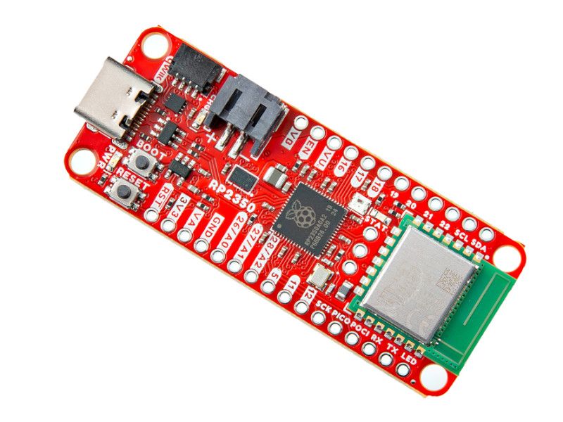
The SparkFun Thing Plus - RP2350 is a dynamic and powerful wireless development platform in the Thing Plus form factor. Built around the RP2350 microcontroller from the Raspberry Pi Foundation, this board includes their radio module for single-band 2.4 GHz WiFi 4 (802.11n) and Bluetooth® 5.2 alon...
inland summit
red panther
Try this UF2 instead https://circuitpython.org/board/sparkfun_thing_plus_rp2350/
So install this new uf2 then drag & drop the files from the project?
buoyant jackal
inland summit
So install this new uf2 then drag & drop the files from the project?
Yes. That’s the UF2 for that board
inland summit
Will I need to alter the projects codes to account for the new uf2
buoyant jackal
inland summit
Will I need to alter the projects codes to account for the new uf2
what UF2 were you using before?
inland summit
buoyant jackal
what UF2 were you using before?
(https://github.com/DavidPagels/retro-pico-switch?tab=readme-ov-file) this is the original project code.
(https://github.com/davidpagels/retro-pico-switch/releases) this is the uf2. I believe it was designed specifically for this project
buoyant jackal
inland summit
(https://github.com/DavidPagels/retro-pico-switch?tab=readme-ov-file) this is th...
This code is in C++, so the choice of CIrcuitPython UF2 is irrelevant. It's not running under CircuitPython.
to use this code, you'll want to check the pin assignments, and maybe move some around if the original pins are not available on this board.
inland summit
buoyant jackal
This code is in C++, so the choice of CIrcuitPython UF2 is irrelevant. It's not ...
Ok so, c++won't work in circuit python in the same way an Xbox game won't work in a ps5?
buoyant jackal
CircuitPython runs python code. It interprets it by compiling into an intermediate "bytecode" language, and then interpreting the bytecodes. C++ code is compiled into machine code.
in the case of Xbox vs PS5, the processors are different (and the operating systems). Here, the RP2350 is the same, but the program itself is not the same.
inland summit
Ok. That makes sense. Is there a converter that will turn c++ into python?
I can work with python easier
buoyant jackal
well, you could ask an LLM to do it, but depending on what it's doing, it may not be so easy. And you really need to convert it into CircuitPython, which has specific interfaces for hardware.
inland summit
What is llm
buoyant jackal
You can compile and run that code using the Pi Pico development tools, but you'll need to point it at a board definition for the SparkFun board, and maybe make some other minor changes, like pins changes, as I said.
buoyant jackal
inland summit
What is llm
AI Large Language Model
i'd suggest trying to work with the C++ to start with. But you'll need to read about build Pi Pico (pico-sdk) projects
inland summit
This was supposed to be a quick easy build to tide me over while I work on the more complex rumble pack version
buoyant jackal
well, you could use the original hardware
does the UF2 in the repo not work at all?
inland summit
buoyant jackal
does the UF2 in the repo not work at all?
Repo?
buoyant jackal
github repository
inland summit
It will work on a pico. Used it with my first build. It doesnt work on this board @ all
inland summit
buoyant jackal
well, you could use the original hardware
Im using the pimoroni pico for the rumble pak. Will the uf2 work on that
buoyant jackal
the repo UF2 is for an RP2040. Your board is an RP2350. Close, but not the same, and you can't make compatible UF2's.
if the Pimoroni is RP2040 yes, assuming the pin assignments work
buoyant jackal
well, don't take it personally 🙂
it's a learning experience
you CAN learn how to build this for RP2350, but if you're not familiar, it will be a slog
Using the specified hw will be much less of a headache
if you are looking for that form factor, you could pick an RP2040 Feather-sized board
inland summit
Will the code files work anywhere with the proper modifications assuming its a c++ environment? Like if I got the proper UF2 file, modified the files & transfered them to the board?
buoyant jackal
the UF2 is the C++ code. Unlike CircuitPython, there is no base interpreter running on the board.
you have to build a new UF2 by compiling the C++ code in the proper environment with the proper C++ compiler
CircuitPython is "just a program", albeit a complicated one. It's a program that runs on a lot of boards, and interprents and runs CircuitPython code.
inland summit
So, all the files in the project are compiled in the uf2. So they need modification, the missing libraries for the board, & compilation
buoyant jackal
Annabelle
 last agate
have any of you guys used the adafruit ANO directional/rotary pad? I'm thinking about using one for a project, it looks kind of fun and has exactly the functionality i need
buoyant jackal
last agate
have any of you guys used the adafruit ANO directional/rotary pad? I'm thinking ...
Here are some projects using it: https://learn.adafruit.com/search?q=ano%2520rotary
it works like a regular rotary encoder
last agate
buoyant jackal
it works like a regular rotary encoder
yeah, the encoder/button/arrow functionality on it is perfect for what i need, i was just curious of anyone had any hands-on experience in the channel and could be like "oh it's sick" or "ehh it's ok but kinda weird to use" kind of thing
 warm jay
I am looking for some bluetooth controlled RGB LEDs.
I can only find either addressable RGB LEDs or only the bluetooth controller. But no 'bundle'.
Any suggestions?
Something like this but instead of IR control I would need one with bluetooth
 buoyant jackal
warm jay
I am looking for some bluetooth controlled RGB LEDs.
I can only find either addr...
buoyant jackal
warm jay
I am looking for some bluetooth controlled RGB LEDs.
I can only find either addr...
WLED https://kno.wled.ge/ has wifi control (not BLE). You use its app.
We have various projects, for example:
https://learn.adafruit.com/circuit-playground-bluefruit-neopixel-animation-and-color-remote-control
https://learn.adafruit.com/pyleap-ble-controlled-neopixels-with-clue
and quite a few more
last agate
Also, has anyone here used the Trellis keypads? I already ordered some and am going to use them, i was just curious how they feel ... is the silicone pad kind of clicky or thumpy, or does it feel more like a soft keyboard, or a firm squish? it doesn't really matter either way, just curious while i wait for the temporal uncertainty of domestic shipping to process. I've watched loads of videos but no one really mentions the tactile side ofi t
 sage moth
So, I'd like to put Android Auto in my car, so I'm looking at the Crankshaft project for raspberry pi, has anyone worked with it? I'm trying to figure out why the brightness sets to 0 when switching from day to night and vice versa with the brightness set, it's not honoring the defaults I have in the configuration
sage moth
apparently a raspberry pi and screen don't get enough power from USB itself, I may need to invest in some form of PD board to supply 5 volts with sufficient amps
buoyant jackal
sage moth
apparently a raspberry pi and screen don't get enough power from USB itself, I m...
what is the USB supply you are using?
sage moth

【QC5.0 Quick Charge】 Latest and unique 165W USB C Car Charger that supports PPS PD3.1 QC5.0 fast charging, 3 ports 100W+35W+30W independent fast charging technology, single port power will not decrease when 3 ports are used at the same time, can quickly charge 3 devices at the same time.
I think I need to just tell it that I have a higher draw device, the MicroUSB on the Pi doesn't tell it there's more juice needed and I think this thing's compliant with power delivery standards
was looking at https://www.adafruit.com/product/5807 and thinking of just cutting the 1A jumper

The HUSB238 USB PD sink chip is neat in that you can either use jumpers (really, resistor selection) to set the desired PD voltage and current or you can use I2C for dynamic querying and ...
buoyant jackal
can you just split the power draw from the the two USB-C ports (or even the USB-A) port: one to the RPI and one to the display?
RPi 5V requirements are high, and kinda non-standard
esp for Pi 4 or Pi 5
sage moth
I'd have to remove the 5V lead on the Pi2's header for that
buoyant jackal
is there a forum or antyhing for the Crankshaft project? I'm sure you're not the first person with this issue.
sage moth
yeah, looking at that
buoyant jackal
obviously those folks are way closer to the issue
sage moth
I think if I use the higher amp ports on the cigarette lighter port adapter I'd be able to push it, but I'd need something like that HUSSB238 to ask the charger for the needed power, if I do that, then it'd just be a matter of injecting it into the 5V pin, which.. admittedly is how I'm powering it on my bench
probably not the smartest thing
buoyant jackal
sage moth
I think if I use the higher amp ports on the cigarette lighter port adapter I'd ...
These chargers are not necessarily completely PD-compliant: you may be able to get the current you need without negotiation. Worth trying.
sage moth
yeah, I don't have a USB-C to MicroUSB adapter to try it
buoyant jackal
sage moth
yeah, I don't have a USB-C to MicroUSB adapter to try it
do you have USB-C to USB-A socket?
 abstract vault
Small update progress so far

 plush elk
On the DC Motor + Stepper FeatherWing Add-on, how do I put power into the power block? Specifically what wire do I use because I don't know what keyword to type in the search bar. If I wanted wall power only, what product do I use?
 buoyant jackal
plush elk
On the DC Motor + Stepper FeatherWing Add-on, how do I put power into the power ...
buoyant jackal
plush elk
On the DC Motor + Stepper FeatherWing Add-on, how do I put power into the power ...
I'm not sure what you mean by wall power Did you read the guide, e.g. https://learn.adafruit.com/adafruit-stepper-dc-motor-featherwing/pinouts
power to be supplied depends on the motors you are using
I saw the deleted messages you posted, about a fairly elementary motor control problem. If you are just trying to turn on one motor, without controlling its speed, this is simple:
https://www.adafruit.com/product/5648
Sparky the Blue Smoke Monster shows up whenever the magic smoke is let out of an electronic component. And his very favorite is whenever folks first start with electronics and robotics: ...
plush elk
buoyant jackal
I saw the deleted messages you posted, about a fairly elementary motor control p...
even if you can't control it's speed, can you still control when it turns on and off? What product would accomplish this?
buoyant jackal
plush elk
even if you can't control it's speed, can you still control when it turns on and...
the product above along with a microcontroller board would allow you to turn it on and off. If you want to control its speed too, then you want a motor controller board
what kind of motor?
plush elk
buoyant jackal
what kind of motor?
I want a TT motor to spin a small water wheel basically. I don't know a single thing about electronics I'm a nature sciences person. I shouldn't need to control the speed, I just need a motor to turn on for 30 seconds, every couple minutes. Does either the mosfet or the microcontroller have a timer feature? Or do I need a 3rd product?
buoyant jackal
plush elk
I want a TT motor to spin a small water wheel basically. I don't know a single t...
you would write a program in the microcontroller to turn the motor on and off. A microcontroller is a tiny computer.
the program would wait for 1.5 minutes, turn on the motor, wait for 30 seconds, turn off the motor, then repeat
Here is an example of activating a solenoid for 1 second, then deactivating it, and repeating: https://learn.adafruit.com/adafruit-mosfet-driver/circuitpython-python#example-code-3133146
It could just as well be a motor
the circuitry on that page uses the 3.3V supply, but you would use the 5V supply or some other supply instead
plush elk
buoyant jackal
you would write a program in the microcontroller to turn the motor on and off. A...
Okay, is the circut playground the only microcontroller that is both solderless and also compatible with the mosfet motor driver?
buoyant jackal
plush elk
Okay, is the circut playground the only microcontroller that is both solderless ...
you could use a breadboard and other microcontrollers with pre-soldered headers. The Circuit Playground (make sure you get the Circuit Playground Express, not the "Classic), is the easiest in terms of connecting alligator clips
is the TT motor slow enough for this water wheel?
plush elk
I would hope that the weight of the wheel slows it down
buoyant jackal
You can also use PWM to slow down the motor
plush elk
or is that not how that works
buoyant jackal
ideally you would not want too much of a strain on the motor
buoyant jackal
but the TT motor is geared down; it has a a noticeable amount of torque
you can adjust the speed of the motor in software
plush elk
but isn't the mosfet driver unable to change speed anyway?
buoyant jackal
yes, the quickest way to get started is:
https://www.adafruit.com/product/3333
https://www.adafruit.com/product/5648
https://www.adafruit.com/product/4030
https://www.adafruit.com/product/3802

Circuit Playground Express is the next step towards a perfect introduction to electronics and programming. We've taken the original Circuit Playground Classic and made it even better! ...
Sparky the Blue Smoke Monster shows up whenever the magic smoke is let out of an electronic component. And his very favorite is whenever folks first start with electronics and robotics: ...

This cable will let you turn a JST PH 3-pin cable port into 3 individual wires with grippy mini alligator clips. We're carrying these to match up with any of our boards or breakouts with ...

These durable (but affordable!) gearbox motors (also known as 'TT' motors) are an easy, low-cost way to get your projects moving. This is a TT DC All-Metal Gearbox ...
does it need to be battery powered, or would you power it from USB (or a USB power pack)?
plush elk
I would prefer a usb with a wall adapter, is that possible?
buoyant jackal
plush elk
I would prefer a usb with a wall adapter, is that possible?
yes, that is fine
do you already have a microntroller board of some kind?
plush elk
None, I have 0 experience with any of this, so this would be the first
https://www.adafruit.com/product/592 what would be the wall adapter for this cord? I can't find anything by typing in usb A
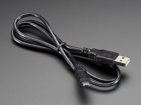
This here is your standard A to micro-B USB cable, for USB 1.1 or 2.0. Perfect for connecting a PC to your Metro, Feather, Raspberry Pi or other dev-board or microcontrollerApproximately 3 ...
buoyant jackal
plush elk
https://www.adafruit.com/product/592 what would be the wall adapter for this cor...
yes, get that too
that is just the required cable (buy that too). Do you have a phone charger or other USB charger?
if not, these are possibilities:
https://www.adafruit.com/product/1994
https://www.adafruit.com/product/1995

Our 5V 2A USB power adapter is the perfect choice for powering single-board computers like Raspberry Pi, BeagleBone, or anything else that's power-hungry!This adapter was specifically ...

Our all-in-one 5V 2.5 Amp + MicroUSB cable power adapter is the perfect choice for powering single-board computers like Raspberry Pi, BeagleBone, or anything else that's ...
red panther
buoyant jackal
I saw the deleted messages you posted, about a fairly elementary motor control p...
This is a cool board! I'm going to start recommending it.
I would complain about the lack of gate driver, but it only has 2nC of gate charge so you can comfortably PWM at over 100kHz.
plush elk
buoyant jackal
if not, these are possibilities:
https://www.adafruit.com/product/1994
https://w...
oh okay thank you I'll get one of those too :D
buoyant jackal
so make sure you get a 592 and one of those power supplies if you dn't have some thing like that already
plush elk
btw is the circut playground + motor mosfet suitiable to also do the same 30 sec on 1.5 min off with the peristaltic 12V motor?

 plush elk
buoyant jackal
so make sure you get a 592 and one of those power supplies if you dn't have some...
plush elk
buoyant jackal
so make sure you get a 592 and one of those power supplies if you dn't have some...
yeah I do have a phone one but I prefer to keep my things seperate
buoyant jackal
do you want a 12V pump or a motor?
plush elk
I have 2 projects, one for the tt motor and one for the pump. I'm just looking to see if the circut playground is good enough for both (I'd be buying 2 circut playgrounds)
buoyant jackal
The 12v pump needs 12V. There is a 5v pump: https://www.adafruit.com/product/3910
Move fluid safely from here to there with this very nice Peristaltic Pump that works with 5V or 6V power. Unlike most liquid pumps, this is a peristaltic type - the pump squishes the ...
12v wall power supply, with 2.1mm barrel jack. To connect to the barrel jack, you can use:
https://www.adafruit.com/product/368

If you need to connect a DC power wall wart to a board that doesn't have a DC jack - this adapter will come in very handy! There is a 2.1mm DC jack on one end, and a screw terminal block ...
The 12v jack will plug into this, and then you can connect wires to the 12v pump
You will supply 12v to the power pin on the MOSFET driver
plush elk
I see, I was wondering how a circut playground can handle 12v since I've heard that micrcontrollers are usually only 5v max
buoyant jackal
The control signal to control the motor is 3.3V and comes from the CPX (Circuit Playground Express). The 12v is not connected to the CPX directly. It is only connected to the MOSFET driver board
plush elk
soldering will be required to connect the terminal block right?
buoyant jackal
no, it has screw terminals
that's why I recommend it for you
you just unscrew the screw, stick the bare wire end in, and tighten the screw
plush elk
and then the wire goes into the mosfet pin? or
sorry I really don't know any of this 😭
buoyant jackal
you can stick a short piece of wire in and grab it with the alligator clip. You could even use a piece of a paper clip
do you know anyone mildly handy who could help you with this?
without just taking over? 🙂
plush elk
it's going in here, correct? One for V+ and GND
 plush elk
buoyant jackal
without just taking over? 🙂
plush elk
buoyant jackal
without just taking over? 🙂
no I don't unfortunately
buoyant jackal
instead of soldering to those holes, you can use the JST-PH cable with alligator clips. It plugs into the MOSFET driver board. You have it in your cart: https://www.adafruit.com/product/4030
This cable will let you turn a JST PH 3-pin cable port into 3 individual wires with grippy mini alligator clips. We're carrying these to match up with any of our boards or breakouts with ...
 plush elk
@buoyant jackal okay I think this is my final question, will this work? In the JST PH, Black is GND, Red is V+. Both are plugged into the 12V power block by alligator clips which are holding small wire segments, shown in brown. The power block is conneted to the 12V wall adapter. The white singal wire on the JST PH is attached to the A1 port of circut playground. Circut playground is connected by USB-B, which is connected to a Wall adapter. The green and blue wires are just the motor wires.
 buoyant jackal
plush elk
<@329766224093249548> okay I think this is my final question, will this work? In...
buoyant jackal
plush elk
<@329766224093249548> okay I think this is my final question, will this work? In...
ALSO, tie the grounds together from the CPX and the 12v supply. You will want another set of alligator clips for this. Unfortunately we are out of a lot of them, but this is still in stock: https://www.adafruit.com/product/1592
Or you can use something like this:
https://www.adafruit.com/product/866

Connect this to that without soldering using these handy mini alligator clip test leads. Approximately 4.5" overall cables with alligator clip on each end, color coded. You get 12 ...

These are like the fancy electronics equivalent of the wire nuts electricians use to bind wires together. They are a lot easier to use as well! Each block connector has a metal block inside ...
you will need some wire and a wire stripper: https://www.adafruit.com/search?q=+wire+spool

We've upgraded our basic 'adjustable' wire strippers to these multi-sized wire strippers. They include: 20-30 AWG strippers, wire cutters, 'plier' tips, and a wire loop. ...
your diagram is fine except for the missing connection to ground on the CPX
The ground connection is necessary so that the control signal is referenced to the 12v ground
for the 5v motor you would use 5v from the CPX board so you don't need the extra ground connection
plush elk
So, the alligator black gnd clip, needs to clip on a wire portion, then that portion is attached to the 3 wire block connector, then from the connector, 2 wires are attached with one leading to gnd on the power jack adapter, and one leading to the A1 CPX port
buoyant jackal
If I am interpreting what you wrote correctly, yes. Here is a picture. I added a new black wire pointed to by the blue arrow:

it needs to connect somewhere to the previous black wire connection, whether by some extra terminal, or whatever. Unfortunately these are out of stock: https://www.adafruit.com/product/3448

When working with unusual non-header-friendly surfaces, these handy cables will be your best friends! No longer will you have long, cumbersome strands of alligator clips. These compact ...
do you live near a Micro Center or similar? You can find our products there. Also sometimes Digi-Key or Mouser have stock when we don't.
plush elk
buoyant jackal
If I am interpreting what you wrote correctly, yes. Here is a picture. I added a...
So the black gnd wire needs to split into two, with one going to the power jack and one going to the CPX. All the while the white singal wire goes into the a1 port and is not altered in any way
buoyant jackal
right
and all the black wires need to be connected together, somehow, your choice
so where that 3-way black-wire connection is above, you could use something like that Waygo snap connector.
plush elk
Which awg wires are suitble for this task and which are not? I'm assuming 30 awg is too thin and dangerous
plush elk
buoyant jackal
do you live near a Micro Center or similar? You can find our products there. Als...
are there any makerspaces / micro centers/ or anything else in LA county? I live there
buoyant jackal
Micro Center in Tustin
plush elk
okay I think that is it for now, I'll buy then assemble things and have it double checked here before I power it
buoyant jackal
good luck!
 buoyant jackal
if you have a makerspace nearby you may be able to get some hands-on help or take a little course, etc.
 snow wolf
Hi everyone,
I'm looking for a 3-phase energy monitoring module that connects to ESP32/Arduino, with specs significantly above the PZEM-004T for industrial-grade use.
My setup:
- 3-phase 4-wire (3P4W) system with a utility meter (EDMI Mk10MI-3P)
- Schneider 3P main breaker (see photo attached)
- Located in Indonesia (230V/50Hz per phase)
- Want to monitor V, I, active/reactive power, PF, and kWh per phase
- Prefer non-invasive installation (CT clamp only, no cutting main lines) if possible
Requirements:
- Accuracy ±0.5% or better
- Safety certified (CE, IEC62053-22, or equivalent)
- SPI or UART interface to ESP32
I'm already aware of ATM90E32AS and ATM90E36A as IC options, and boards like CircuitSetup and IPEM (DitroniX) — but I'm wondering if there are other ready-made modules out there that are:
- Plug-and-play like PZEM but industrial grade
- Already carry safety certifications out of the box
- Have good library/community support for ESP32
Has anyone deployed any of these in a real industrial setting? Any recommendations or experience with certified alternatives would be hugely appreciated.
Thanks in advance!

 modern violet
Is anyone aware of a workaround for connecting the new mwx01 mini thermal printers to the Memento?
I've been following the old guide for the cat printer, but all newer versions of the cat printer seem to use a mwx01 firmware, rather than the mx06 firmware. The uf2 file from the guide seems to be incompatible with this newer firmware, so I've been stuck in a 'Can't connect to printer, resetting' loop
 honest drift
If my Adaftuit ultimate gps breakout refuses to get a fix and never sends ant replies through serial, it may be damaged right?
It worked at some point, I've made sure RX and TX aren't swapped as I've tried both ways.
in_waiting is just always 0, data read is always none
Only way to change that is to connect the GPS Rx and Tx who just shows what I'm sending
honest drift
Yeah my GPS is dead :/
Is it possible to do a guesstimate based on altitude calculated from pressure and IMU Yaw Pitch Roll + Linear Acceleration?
warm jay
I am looking for a small sliding switch.
Roughly the size of this one here (6.5 mm length)
https://tech.alpsalpine.com/e/products/detail/SSAJ110100/
The "problem" I have with this one is that it might be a bit difficult to attach a plastic cover to it so that it's easier to use
SSAJ Series SSAJ110100 Operating direction : Horizontal ・ Mount height : 0.7mm ・ Travel : 1.4mm ・ Rating (max.) : 10mA 5V DC ・ Number of poles : 1-pole
 gritty birch
I'm brainstorming a solution for a raspberry pi project. The raspberry pi is mounted inside a waterproof enclosure along with an MPPT solar controller and a biggish LiFePo4 battery. I want to have a waterproof solution to connect the solar panel to the controller inside the case. The controller uses an xt30 connection. The problem is I want it to be fairly easy to disconnect the solar panel from the enclosure. I know I can make the connection by passing a wire through a cable gland, but from what I know, that doesn't allow for easy disconnect. I was thinking maybe a bulkhead connector, but I haven't been able to find a waterproof xt30 bulkhead connector. Any other ideas?
red panther
gritty birch
I'm brainstorming a solution for a raspberry pi project. The raspberry pi is mou...
There are a lot of “waterproof” connectors, but their actual performance varies widely. What do you need for voltage and current? Does it need to be waterproof when not mated? Should it withstand rain or submersion? Do you prefer solder or crimps?
I am assuming you’re targeting minimum cost and small size.
gritty birch
cost doesn't need to be minimal, this is a one-off just for fun/learning. If it's more than the enclosure, that's a non-starter. There's a good bit of space in the enclosure too, so size isn't too important, but there are limits. The solar panel is rated for 110W, 18.4V@6A
Waterproof: more is better, but rain is probably sufficient. The panel might be left outside even when not in use, so yeah, it would be good to have the connectors be waterproof even when not mated. Mild preference for crimps, but solder is fine too.
red panther
This looks pretty good. Let me see if I can find the mate... https://www.digikey.com/en/products/detail/amphenol-ltw/ABB-02PMMS-LC7001/7617195
I think it's this? Please confirm https://www.digikey.com/en/products/detail/amphenol-ltw/BB-02BFFA-LL7001/7617438 Not sure if the plug is waterproof when unmated
buoyant jackal
https://cdn-learn.adafruit.com/assets/assets/000/110/655/original/6.1-RuggedizedCablesConnectorsInterfaces.pdf suggests SP connectors (that is a link off a product page)
looks very similar to what Marshal linked to
also M connectors
gritty birch
red panther
I think it's this? Please confirm https://www.digikey.com/en/products/detail/amp...
I'm suspicious of the fact that the dates are very different on the datasheets, off by like 5 years
red panther
Here's my search if you want to look at other options. Be wary of the crimped connectors - those typically aren't waterproof when unmated unless they're mil-spec, which adds a lot to the cost. https://www.digikey.com/en/products/filter/circular-connectors/circular-connector-assemblies/436?s=N4IgjCBcoGw1oDGUBmBDANgZwKYBoQB7KAbRACY5KIDyBWcgThnJFoA4AGAdk-bYq8ALHwHlhAZhqDOQoXTGMJ3ckIETZ7RowEq507o3Yxuuzp2bTj7SgMbkwyu3BjSwnemDc8YQ-gS8HVwF3Rm46UwCwOnZ2NSjGIUcQoXJZHQC6OSdM9gkYCRC8oSUi9jAYf3AlG04xB0TWWmVuIUKAXQIABwAXKBAAZR6AJwBLADsAcxAAXwJYhBBkSHRsfCJSCiZOLJCHCVsA-bp4I8c4vfPTkCFuXlEAmHtGBUelLxCng6bwL-JCt4SDSfJQMMScKQmcEHB4UCHkejQhGROEHfJIugA1H0KoIxjmaR4iHxLb4iSvUkQ65EnKUtogTogXr9IZjKazAhPUzQJaoTC4AjESBkcnaCwCAomLQSowSITXUVGEmK9golV1AiKxjSLU-LVYrXKujaF7qY0m9QwcwnS3Wqo2cofTVWzjBAjcF3aW2un6pPg7M3aOgakCKzGB2Xeq1Rg0umAU-LmOC2rxVRNgBwphFZknhO48FMHQuxziOBVWxxqiu7Z2lugJivRghtDxA3RWkoU4xtAq2tJVjzizkRVQUv0FLHjpIM7p9SCDEYTaZzcCuiA85arAUbYWh-7hBX7iLqfcsE-KXuakptNXPDwzplzhds5cBIw6Dd8taCzZ1dorgBaD8kCgEYAFd1iFMgIH-AgANYT9IHAyDNgUf8V3gHlRgAE36AD3GkZl5wEABHHoAE9%2BncAQKK6HB%2BjQLBkBmGYgA
Also, DigiKey's price sort is messed up this week. I don't know what's going on
gritty birch

SZJELEN SP21 2Pin-12Pin Panel Mount Waterproof Aviation Connector Plug and Socket IP67,LED Electrical Power Cable Wire Connector (2Pin)
does that look viable?
red panther
gritty birch
does that look viable?
Looks ok. It's a back-side nut, so you may have to put it through the hole before you terminate the other end. Make sure the connector can handle the cord diameter of your solar panel
red panther
Actually, the panels on my roof have two wires instead of a bundled cable. I wonder if yours is like that too?
 prime falcon
hey folks! 👋🏻 i am working on a small project to build a clock with an RGB Matrix panel, but the panel stays completely blank/black every time i run the demo app. i feel like i’ve ruled out most of the basic stuff, but i’m still getting a totally black display.
hardware:
Raspberry Pi Zero 2 WH
Adafruit RGB Matrix Bonnet (3211)
Adafruit 64x32 RGB LED Matrix, 3mm pitch (2279)
5V 4A power supply (Qualtek QAWA-24-5-US01)
Also tested with a second/new bonnet
Also tested with a second/new ribbon cable
Also tested with a second matrix panel: Adafruit 32x32 (2026)
what i verified:
Demo command for 64x32: sudo ./demo --led-rows=32 --led-cols=64 --led-gpio-mapping=adafruit-hat -D 0
Also tried 32x32 command for the other panel
SSH’d into the Pi and confirmed I’m actually on the Pi
The demo starts and stays running with no errors besides the normal isolcpus=3 suggestion
wiring/troubleshooting done:
Bonnet is seated firmly on the Pi header
Ribbon cable tested on both original and replacement cable
Panel power connected to VCC/GND correctly
Measured ~5.12V at bonnet screw terminals
Measured ~5.10–5.13V at panel power connector with a multimeter
Swapped in a brand new bonnet
Swapped in a brand new ribbon cable
Swapped in a second panel (32x32) and got same result
weird symptom:
The panel stays completely black during demos, but if I unplug the Pi USB power while the 5V matrix power is still connected, I briefly see 1–2 rows / random flicker on the panel.
at this point I’m wondering: does this sound like a Pi Zero 2 WH GPIO/header issue? any known compatibility issue with this stack? would appreciate any input!
red panther
It’s the 3.3v one with UART?
Cool method, sending the ultrasonic pulse through the water instead of the air
 brisk dust
3.3 to 12v
buoyant jackal
prime falcon
hey folks! 👋🏻 i am working on a small project to build a clock with an RGB Mat...
The Pi Zero +V power should not be tied to the other 5V supply. The grounds should be tied together.
I suggest you open a thread on https://forums.adafruit.com. Include pictures and descriptions of your wiring, what OS version the Pi Zero is running, which guide are you following, etc.
brisk dust
It's to measure beer in bright tanks at job. Since the tanks are under pressure I can't put things in it.
brisk dust
red panther
It’s the 3.3v one with UART?
Thanks for the file
brisk dust
red panther
Cool method, sending the ultrasonic pulse through the water instead of the air
For inox pressurized beer bright tanks.
red panther
Nice! So what’s going on? Do you see any communication back from the sensor?
I guess I assume everyone has a scope, which isn’t true. But you could find out with an LED
My cheap FTDI boards have the LEDs built in, very handy
The datasheet really doesn’t say much. I found some discussion on the Arduino forums https://forum.arduino.cc/t/how-to-read-serial-data-from-non-contact-ultrasonic-liquid-level-sensor/507781/16
Arduino Forum
I added some questions while you were typing... You mean you held it tight up against the bottom (outside) of various containers? Did you use the adhesive? Seems like it probably needs the adhesive for proper coupling. Did you try steel containers? What wall thickness and size? Also, it would be interesting to hold the "business end" of the s...
It’s not even clear if the voltage levels are TTL or true RS232
brisk dust
red panther
Nice! So what’s going on? Do you see any communication back from the sensor?
Still in the bag, just got it. Going to prog it later today to test it at job monday.
prime falcon
buoyant jackal
The Pi Zero +V power should not be tied to the other 5V supply. The grounds _sho...
thanks, i created a thread yesterday https://forums.adafruit.com/viewtopic.php?p=1087209
brisk dust
red panther
The datasheet really doesn’t say much. I found some discussion on the Arduino fo...
Was reading it earlier this week
red panther
brisk dust
Still in the bag, just got it. Going to prog it later today to test it at job mo...
I hope it works! Is the brite tank single-walled at the bottom or does it have the glycol sleeve there too?
brisk dust
red panther
I hope it works! Is the brite tank single-walled at the bottom or does it have t...
Single walled they are in a cold room.
brisk dust
red panther
I hope it works! Is the brite tank single-walled at the bottom or does it have t...
 red panther
You may have to play around with adhesive methods, as I expect double-stick tape will not work on a curved surface. I think there are some puttys used for accelerometers that might work
brisk dust
The view glass on top are always foggy
brisk dust
red panther
You may have to play around with adhesive methods, as I expect double-stick tape...
Going to try the ultrasound gel method first. So I can test on different vessels. I got 12 tanks to monitor
red panther
I’ve never used it. Is it sticky enough to hold the sensor on?
brisk dust
My boss thinks the idea is a waste of ressources. But having losses in beer is bad
brisk dust
red panther
I’ve never used it. Is it sticky enough to hold the sensor on?
For the test it will be a manually hold in place method. And I'll also try the lateral detection on the side as a level identification too
Like if the sensor was an nf one
I can 3d print a bracket to hold it too.
Should I use the pico or an esp32 s2 wroom?
red panther
I always prefer the pico, but it’s up to you
ESP32 has deeper sleep modes, if you’re running on battery, but nRF is even better for that
brisk dust
For now it will be on pico with a breadboard. I wonder if I add a display or not.
brisk dust
I'll need a way to test the codes via my android device. Do you know a good app for that?
red panther

Terminal for serial devices connected with USB to serial converter
Or if you don’t want a cable, there’s this https://www.adafruit.com/product/2479

Would you like to add powerful and easy-to-use Bluetooth® Low Energy to your robot, art or other electronics project? Heck yeah! With Bluetooth® Low Energy now included in ...
brisk dust
Now I can't seem to have it reading properly
But I have not looked at a lot of codes yet
brisk dust
Rx tx pins had to be inversed in the connector...
brisk dust
The terminal result. Yup I print data to see if it changes
 brisk dust
Why do I have xFF instead of 255?
buoyant jackal
brisk dust
Why do I have xFF instead of 255?
0xff is 255 in hex
looks like you're printing a bytearray or a bytes. each byte is printed either as a printing character (like "a") or if not recognized as a printing character, as a hex-escaped character
brisk dust
Ok, now it aways gives me 0mm. I switched rx and tx wires in the connector. Since on the dev hat I have GPIO4 and GPIO5 are under the 5v and gnd just over them
 red panther
brisk dust
Ok, now it aways gives me 0mm. I switched rx and tx wires in the connector. Sinc...
red panther
brisk dust
Ok, now it aways gives me 0mm. I switched rx and tx wires in the connector. Sinc...
Can you try on something easier like a plastic container full of water? 5 gallon bucket should work
I think nobody is really sure if it works through the stainless tank
brisk dust
Will do later this week. Got a huge week. Brewing 3 days.
brisk dust
red panther
I think nobody is really sure if it works through the stainless tank
Seem so.
red panther
I was really hoping it would though. The other options are not good.
 fringe vessel
Hello im working on a project that uses the ultra flexible white led strip for a small rectangular stage. Could anyone tell me what parts that I should order alongside the 1m strip so that I can use it. Or is it a plug and play kind of thing?
red panther
fringe vessel
Hello im working on a project that uses the ultra flexible white led strip for a...
Depends on the strip. Some are 5v, some are 12v, some are 24v. Generally they have resistors built in and are fairly forgiving. Also different strips draw different amounts of current at a given voltage.
buoyant jackal
fringe vessel
Hello im working on a project that uses the ultra flexible white led strip for a...
what is the adafruit part number or link?
There are multiple strips: https://www.adafruit.com/search?q=ultra+flexible+white. The product description says whether they are 5v or 12v or something else
fringe vessel
buoyant jackal
what is the adafruit part number or link?
This is the product link. Thanks for the help 😃 https://www.adafruit.com/product/4612#technical-details
Here at Adafruit we love discovering new and exotic glowing things. Like moths to the flame, we were intrigued by these 'chip on board' ultra-flexible white LED Strips with 480 SMT ...
fringe vessel
red panther
Depends on the strip. Some are 5v, some are 12v, some are 24v. Generally they ha...
^^
red panther
12V 1A should be plenty. Check your local thrift store.
fringe vessel
what kind of connection is it? do I just need 12v 1a acdc power chord? i was looking at the other connections and they used micro controllers to connect them
red panther
Yeah, it’s 12VDC. More than a microcontroller can supply unaided. There’s a red and a black wire soldered onto the end. Red is positive.
Terminal blocks are a nice long-term solution for connecting them. I think the new fad is the Wago lever nuts
Of course you can do classic options like soldering or spade terminals
But if you do want to turn it off and on with a micro, there’s this cool option https://www.adafruit.com/product/5648?gad_source=1&gad_campaignid=21079227318
Sparky the Blue Smoke Monster shows up whenever the magic smoke is let out of an electronic component. And his very favorite is whenever folks first start with electronics and robotics: ...
fringe vessel
thank you 🙏 @red panther
 fading plinth
I am going through it trying to make a HUB75 display arcade machine. I have a raspberry Pi 5 (3.3V logic) connected to a Matrix Portal (3.3V logic), connected to my Hub75 boards. I am coming across 2 problems. The first is that when I run test code just through the matrix portal (not involving the Raspberry Pi) the data which appears on the screen is incorrect, the wrong color, stagnant etc. The other issue I am coming across is when using ssh to communicate with the Raspberry pi, it is saying that there is nothing connected to the rx/tx port event though the baud rate is the same for the matrix and the pi and they are connected through a common ground. I feel like replacing the matrix portal but I'm convinced it could be a hardware issue where both the Hub75 and Matrix are broken the night before I present at 9am.
If anyone has some advice that would be incredible
 red panther
I can’t help with the hub75 board, but I have experience with ssh. Are you saying that the serial port works when you log into the Pi directly (with display and keyboard, I suppose) but not over ssh? If so, I expect you are logging in to two different accounts.
Or perhaps you’re saying that the serial doesn’t work and ssh is simply your preferred mode of access. In this case we can narrow it down. Connect rx and tx and see if your messages are returned. (It’s called a serial loopback for this reason). If so, connect back to the matrix portal. Remember Tx on the pi should be wired to Rx on whatever you’re trying to talk to. Verify your baud rate, parity, stop bit, etc
By the way, what program are you using for the serial port? GNU Screen is a classic, but tio is the new kid on the block
Screen is also used as a terminal multiplexer, but I never figured out how to do that AND use a serial port, so I switched to tmux
brisk dust
red panther
I was really hoping it would though. The other options are not good.
I have to get some ultrasound gel for my testing tho. The interface is not good without fixation.
fading plinth
red panther
I can’t help with the hub75 board, but I have experience with ssh. Are you sayin...
The Matrix Portal was/is connected directly to the raspberry pi 5 through rx/tx connections. I used ssh connection through my computer (since I have no compatable keyboard) and when I sent a check through to see if they were communicating there was no response from the matrix portal even though both were powered, on, had a common ground, and were connected through pin 8 and 10 on the Pi (Tx, RX) and the tx and rx pins on the matrix
 crude wigeon
Hi, I need some help with a NeoPixel Ring 24 setup. I’m working on an interactive art project using 5 rings (24 LEDs each) and 5 RFID readers connected to an Arduino Mega.
Right now, one of the rings is malfunctioning. All the rings are powered by a 5V 10A power supply. Everything was working fine last night, but I disconnected the rings and power from the Arduino so I could bring the project home from university.
Today, after reconnecting everything, one pixel on one of the rings lights up blue even when the Arduino isn’t powered on.
Does anyone know what might be causing this or how to fix it? I don’t have much experience with electronics since I’m an art student, so please bear with me. Thanks in advance!


 fringe vessel
This is the product link. Thanks for the help 😃 https://www.adafruit.com/produc...
fringe vessel
fringe vessel
This is the product link. Thanks for the help 😃 https://www.adafruit.com/produc...
Is there a way to be able to control the brightness of the lights for a controlled lab setting
red panther
fringe vessel
Is there a way to be able to control the brightness of the lights for a controll...
Too bright for you? You could dim with a screwdriver and LM2596. Or you could do PWM with a microcontroller and that mosfet driver
Or a rheostat 😂
buoyant jackal
you could try a lower voltage, down to say 9v, but it's not as effective as PWM
If you are in a lab maybe you have a variable DC supply you can experiment with. Don't go above 12v
buoyant jackal
crude wigeon
Hi, I need some help with a NeoPixel Ring 24 setup. I’m working on an interactiv...
does the project work otherwise? The single LED may be coming on by itself due to noise. If you power up the microcontroller first, and then the rings, that may help
make sure the grounds of the rings and microcontroller are tied together (but NOT the 5v lines)
inland summit
For this (https://blog.4dcu.be/diy/2023/12/03/pi-pico-usb-c.html) where should I wire in the resistors exactly?

4DCu.be
With USB type C ports now commonplace, keeping micro-USB cables around for some devices can be a bit of a nuisance. The convenience of a single, reversible ...
Im planning on using something like this (https://www.adafruit.com/product/5467) so I technically dont need to worry about usbc stuff but I want to be prepared for all cables

If you love power adapters or toys & gadgets that have magnetic connections, you can now experiment with these futuristic connectors easily. It's sorta like a DIY ...
 spice orchid
if i need to read & configure multiple i2c sensors (camera, spectral, etc) would it be safer to do bare metal on a feather with stemma, or would a general purpose (linux) OS on rPi be fine with stemma board connected to GPIO? My main concern is i2c timing
red panther
spice orchid
if i need to read & configure multiple i2c sensors (camera, spectral, etc) would...
I2C is slow. The fastest option is to use multiple I2C ports.
red panther
I guess I misread, you said “safer” not “faster”. What unsafe condition are you anticipating?
buoyant jackal
spice orchid
if i need to read & configure multiple i2c sensors (camera, spectral, etc) would...
an RPi is fine, in general. There are some quirky I2C sensors that don't obey the I2C protocol that well, but what you are describing sounds fine.
there are plenty of people who use an RPi to read I2C sensors.
spice orchid
red panther
I guess I misread, you said “safer” not “faster”. What unsafe condition are you ...
one sensor is the AS7343, if i recall each channel needs to be read individually (I could be wrong about this). But if true, is it possible i read channels 1-5 during integration cycle #0 and 6-12 during cycle #1 and get corrupted data? Just wanted to make sure i read these reliably. I was thinking 3 scenarios
(1) Android phone <-- USB / I2C bridge --> sensors,
(2) rpi <--> sensors, and
(3) ESP32-S3 <--> sensors
I was wondering which would be the most reliable
red panther
spice orchid
one sensor is the AS7343, if i recall each channel needs to be read individually...
If a sensor requires high throughput, best to put it on its own bus regardless of platform. MLX90640 is like that too. If you are worried about the delay between subsequent transfers, you will need to hook up a logic analyzer and see for yourself. The cheap 24Mhz 8 channel analyzers are more than adequate for this purpose and easy to use with the Pulseview fx2lafw driver
 wet shore
I'm putting together an RGB cabinet lighting project with an arduino nano and 6 daisy chained neopixel jewels. I'm running it on a 5V 2.5A power supply and powering the pixels direct from the psu not through the nano.
I figure the jewels will draw a max of about 2.4A at full brightness - which I can limit in the software. The total wire run for all the jewels will be around 5m with 0.5-0.7m between jewels.
Do I need an power capacitor and/or data line resistor in this setup ?
red panther
You’re referring to this guide? The tips seem to be to increase the reliability and longevity of the project. https://learn.adafruit.com/adafruit-neopixel-uberguide/best-practices

Everything you always wanted to know about Adafruit NeoPixels but were afraid to ask
buoyant jackal
wet shore
I'm putting together an RGB cabinet lighting project with an arduino nano and 6 ...
see above. As Marshal mentions, these are desirable but not always necessary.
In the setup you describe, consider feeding power to the strips at the far end as well as the near end, and maybe at least one place in between as well. This ameliorates voltage drop along the strips.
inland summit
If I wanted to make a display for coding on that uses alphanumeric displays, how would I go about that?
wet shore
red panther
You’re referring to this guide? The tips seem to be to increase the reliability ...
That wasn't specifically what I referenced but that's the general gist. I want sure because the neopixel jewels have caps and resistors on the board already and the guide seems to talk mostly about neopixel strips.
buoyant jackal
inland summit
If I wanted to make a display for coding on that uses alphanumeric displays, how...
"display" is pretty general here, so more specificity would help
inland summit
buoyant jackal
"display" is pretty general here, so more specificity would help
I want it to display lines of code. No visual displays, no internet, just code
 noble fossil
inland summit
I want it to display lines of code. No visual displays, no internet, just code
noble fossil
inland summit
I want it to display lines of code. No visual displays, no internet, just code
do you have some sample photos of what sort of display you’re thinking of? many “alphanumeric” displays are fairly limited (uppercase only, few symbols). or maybe they’re coarse dot matrix with full ASCII, but only 40x4 or something
or are you maybe thinking of something more along the lines of an old school VGA laptop in text mode?
red panther
If you’re going for retro style, this site has examples https://stocksclocks.com/index.php/word-clocks-angry-electrons/

Word clocks fuse timekeeping with the occasional word or three. Many years ago, alphanumeric tubes (like B7971's) were used but they have become extremely expensive due to their rarity. Angry Electrons has designed a number of word clocks using relatively inexpensive displays, like alphanumeric LEDs or IV-4/17 Russian VFDs. There is also a B7971...
I wonder if you could make your own Nixie tubes with tungsten wire and a vacuum pump?
inland summit
noble fossil
do you have some sample photos of what sort of display you’re thinking of? many ...
I was thinking these (https://www.adafruit.com/product/2154) just tiled out for a couple of rows, maybe a 30x10 character display. Unless lower cased letters are needed in the code, im fine with it being capitalized.

Display, elegantly, 012345678 or 9! Gaze, hypnotized, at ABCDEFGHIJKLM - well it can display the whole alphabet. You get the point. This is a nice, bright 14-segment alphanumeric display ...
inland summit
red panther
If you’re going for retro style, this site has examples https://stocksclocks.com...
I thought of going nixie but never had great luck with high voltage
red panther
Ok. Have you figured out the dimensions and power requirements of a 30x10 14-segment display?
Could draw 12A if half the LEDs are lit ☀️
Maybe a 14” diagonal display?
Ambitious but doable
noble fossil
i’ve seen maybe up to 80x4 for a character LCD that could do full ASCII, but i think those were custom for a portable word processor or note taker
red panther
Gonna take 300 SPI shift registers
Probably want a modular design so you can order 150 boards and snap them together
And then the display driver… who knows??? Not my cup of tea
noble fossil
the LEDs you’d almost certainly want to multiplex somehow
but i don’t know if you’d get an acceptable flicker rate with only driving one character at a time
wet shore
buoyant jackal
if these are for long-term use, see <https://learn.adafruit.com/adafruit-neopixe...
So I'm not using strips I'm using individual neopixel jewels. I'm not super concerned about longetivity as they're probably not going to get a ton of use.
Basically these are lighting for a series of Lego display shelves in our theatre room. The room doesn't get much use so it's going to be more of a "hey check this out" party trick than a permanent lighting system
gritty birch
inland summit
I thought of going nixie but never had great luck with high voltage
What about VFDs? are those too much voltage?
Something like this: https://newhavendisplay.com/4x20-character-vf-glass-display-5x7-dot-matrix/

Newhaven Display
This 4x20 character Vacuum Fluorescent Display illuminates green characters on a black background. This VFD glass display delivers high contrast characters while offering a wide operating temperature range from -40 to 85 degrees Celsius to withstand more extreme temperatures. This 5x7 dot matrix display operates at a voltage of 4.4 Vac and is Ro...
inland summit
gritty birch
What about VFDs? are those too much voltage?
Might work if it comes bigger
buoyant jackal
wet shore
So I'm not using strips I'm using individual neopixel jewels. I'm not super conc...
Sorry, I misread and though you were using 5m of strips, not just 5m of wire. Then what you are planning sounds fine. You could get away without the cap or the resistor.
buoyant jackal
inland summit
Might work if it comes bigger
So is this project meant to illustrate aesthetics of a coarse character-only display? A regular pixel-based display can of course display only text.
is it an art piece?
gritty birch
inland summit
Might work if it comes bigger
Once upon a time there were bigger VFDs, I'm not sure if anyone makes them much bigger than that anymore.
they've fallen out of favor
Noritake also makes some, feel free to poke around further, but here's the biggest I can casually find: https://www.newark.com/noritake-itron/gu126x64f-k612a4/display-vfd-blue-green-41-5mm/dp/01M7904?CMP=KNC-GUSA-GEN-PMAX-Shopping-New
wet shore
Dang shipping from US > AUS from adafruit is pricey =\
red panther
Yeah, it’s halfway around the world. Did you check the Aussie distributors?
wet shore
Its definitely gone up over the years. For some reason I was convinced the item I was after was only available at adafruit but I just found it on core. No idea why I couldn't find it before.
inland summit
buoyant jackal
is it an art piece?
Functional piece to code on
buoyant jackal
inland summit
Functional piece to code on
all the character LCD displays like https://www.adafruit.com/product/398 that I know of have incomplete character sets. Is this to have a minimal coding environment? Would a GUI-less display setup be as good?
This is a fancy upgrade to standard 16x2 LCDs, instead of just having blue and white, or red and black, this LCD has black characters on a full color RGB-backlight background! That means you ...
inland summit
These ones are a little small but would work. Wanted to do the other ones for a challenge but it might be a little outside my capabilities. & yes, minimal coding environment
noble fossil
inland summit
These ones are a little small but would work. Wanted to do the other ones for a ...
what languages? most modern programming languages are too verbose for less than 80 columns
inland summit
noble fossil
what languages? most modern programming languages are too verbose for less than ...
Python languages & maybe c++
brisk dust
@red panther I managed to make it work on a stainless cambro. I'll need a way to install it on the bright tank.
 shut locust
Hi everyone! I'm working on a project where I'd like to use the Adafruit INA228 breakout board, but I noticed the onboard shunt resistor only supports up to 10A, and my project requires measuring higher currents (around 30A).
Is there a way to use an external shunt resistor instead? How should I physically configure the board to bypass the onboard 15mΩ shunt and use my own external one? I couldn't find clear information about this in the official guide.
Thanks in advance!
buoyant jackal
shut locust
Hi everyone! I'm working on a project where I'd like to use the Adafruit INA228 ...
Some discussion of that here: https://forums.adafruit.com/viewtopic.php?p=1005152
that is the most interesting thread; there are some others
red panther
shut locust
Hi everyone! I'm working on a project where I'd like to use the Adafruit INA228 ...
Copper wire has a temperature coefficient of 0.39%/C which could severely limit the accuracy. Are you sure you don’t want to use a sensor that can actually handle the 30A?
shut locust
We need to measure voltages around 30V and currents up to 30A in a solar panel system that involves 3 panels, charge controller and batteries. Precision is not critical but I'd like reasonable accuracy. What sensor would you recommend? Thanks btw
red panther
I have an analog Allegro sensor that goes up to 100A. Hard to solder with an iron but should be easy with a hot plate. DFRobot made a breakout for the 50A version https://www.dfrobot.com/product-2639.html

Unlock the potential of your projects with the Gravity: Analog 50A Current Sensor. Perfect for motor control and circuit protection, ensuring energy efficiency.
red panther
Pololu has some options too https://www.pololu.com/category/118/current-sensors
Make sure the one you pick can handle 30A continuous. Some of the little chips can only do full current for a brief period

An assortment of unidirectional and bidirectional current sensors. They offer a very low-resistance current path and electrical isolation between the current source and the measuring circuit. You can use these sensors to monitor your motor current, detect current spikes, or even to make inexpensive current probes for your oscilloscope.
I normally don’t like to advertise competitors products, but in this instance the Adafruit sensors just don’t go up to 30A
Anyway, if you don’t like any of these options we can see what LEM or Texas Instruments have to offer
 gray basalt
What are good starter projects would you think? I think having some good starter links pinned to the channel would be tops
 molten iris
The Learn Guides have a beginner tag: https://learn.adafruit.com/guides/beginner
buoyant jackal
Post here for project help that doesn't fall into #help-with-circuitpython, #help-with-arduino, or another #help-with- category. Also see https://forums.adafruit.com, which is Adafruit's official support channel. And see https://learn.adafruit.com for thousands of projects and tutorials.
buoyant jackal
buoyant jackal
Post here for project help that doesn't fall into <#537365702651150357>, <#53736...
 twilit glade
hello everyone, i have a question. i am building a gt3 style racing wheel for sim racing, that wheel has 11 buttons and 3 rotory encoders with a push function. now my question is what kind of board can i use for that project? because a arduino pro micro has to little amount of pins? or am i seeing it wrong?
actually i have 2 more buttons for paddle shifters
 hard ocean
twilit glade
hello everyone, i have a question. i am building a gt3 style racing wheel for si...
hard ocean
twilit glade
hello everyone, i have a question. i am building a gt3 style racing wheel for si...
If you wire everything directly, the arduino pro micro would have too little amount of pins, but you could actually wire your buttons up in a matrix
with a matrix you can definitely wire everything with the pin limit of the pro micro
twilit glade
Ah yeah i thought that i needed to do that
hard ocean
i mean you could also use another board but a matrix is a good option
twilit glade
I have never used a matrix, can i build one myself? Or do i need to order 1?
twilit glade
Okay, there are prob tutorials for som like that?
hard ocean
For the code on the otherhand, you should be able to use https://github.com/victorsvi/MatrixKeypad library, should make it pretty easy

GitHub
Simple to use Arduino library to interface matrix keypads. - victorsvi/MatrixKeypad
hard ocean
twilit glade
Okay, there are prob tutorials for som like that?
Let me see if i can find any good ones
twilit glade
Thank you!
hard ocean
twilit glade
Okay, there are prob tutorials for som like that?
This tutorial seems nice
https://www.youtube.com/watch?v=dop0SoD2XL8

In this video I'll show you how to make a button matrix and get the maximum amount of buttons on your microcontroller, whether you're using the rr_configurator software or not.
Support realrobots at https://www.patreon.com/realrobots
Get the software and firmware at
https://gitlab.com/realrobots/rr_configurator
Discord: https://discord.gg/Qzr...
im watching it myself right now 😄
buoyant jackal
twilit glade
Thank you!
also easily done in CircuitPython, but not with an Arduino Pro Micro: https://learn.adafruit.com/key-pad-matrix-scanning-in-circuitpython
 quasi knot
is there an off-the-shelf 24v digital temperature control module that can reach 300c? I am making a "3d pen" for fiber filled nylons out of some spare printer parts and that is the critical missing peice. I would like to avoid using a dedicated printer control board if I can.
 upper escarp
I need some help with simple pots! I have three 10k pots connected to the A3, A4, A5 pins on a Feather M4. This is on a breadboard. The readings are incredibly noisy! I'm using the ResponsiveAnalogRead library, but it's not enough. Am I doing the HW set up wrong? Is it because it is breadboarded?


Bigger caps? Do I need opamps in there?
Also possibly an issue: Those are Adafruit "works great for breadboarding" pots... but they don't sit as nearly as securly as I'd like, and I had to bend the side wings to get them in...
 fleet terrace
upper escarp
I need some help with simple pots! I have three 10k pots connected to the A3, A4...
fleet terrace
upper escarp
I need some help with simple pots! I have three 10k pots connected to the A3, A4...
is GND on the breadboard connected to GND on the Feather?
upper escarp
Yeah... a little hard to see - the black/white ribbon pair to the top is then wired back to the power/gnd rail via those two green jumper wires
And that's a 100nF cap under those green wires between power and GND
red panther
What is the 1k resistor for?
If you’re intending a low-pass filter, it should be between the pot and the cap
But with a 10k pot, the equivalent resistance of the pot will dominate most of the time except when all the way up or down
It might be informative to put a scope probe at your A3/4/5 pins and see what the ADC is seeing
upper escarp
It was in a circuit I copied... Then later added the cap from the wiper at some forum posts suggestion...
red panther
Ok
Let’s do some calculation
What is the highest frequency you want to see?
Alternatively, how fast do you need the pots to respond?
upper escarp
100hz would be great... But could be half that
Controlling synth parameters, so should feel smooth
Even reading 20x a second might be okay... A little less smooth than I'd like
red panther
Ok. So let’s pick 100Hz as a corner frequency. The formula is 2*Pi*Freq = 1/(r*c)
Let’s say r=3.5k because that’s the combination of the 10k pot at halfway plus the 1k
That comes to 454nF. So your cap is about right
But put the 1k between the cap and the pot
upper escarp
Okay... I had tried it.. still glitchy... But I'll rewire and take a scope picture
red panther
Also take a look at Aref
upper escarp
(after lunch! 😁 )
upper escarp
Should I be using Aref for the + side of the pots?
And should we just drop the 1k resistor? I assumed it was extra protection for the SAMD51
 oblique bone
Hey again folks. Does anyone here have a portable RP5 device like a cyberdeck? I'm toying around with the idea and am curious about how people are getting 5A at 5V to the device. I'm familiar with LiPo batteries having 3.7V. I'm curious about how combined series and parallel pairs of batteries increasing voltage and lifespan, then regulating down to 5V. I'm not yet sure how that would affect charging though.
Now that I think of it, I think I backed my way into making a home made laptop battery? Maybe I answered my own question lol. Any input based on personal experience is still greatly appreciated
fleet terrace
upper escarp
Should I be using Aref for the + side of the pots?
And should we just drop the ...
No. AREF is meant to be a reference input to the Microcontroller.
upper escarp

So, caps put after the 1k resistors... pink is Aref, yellow is my synth output (after the DAC) - and blue is one of the pots, measured over on the feather tripler pin
You can see from the MEASURE line on the scope, that the P2P is 200mV... which seems like a pretty big swing for something that goes 0V to 3.3V.
Zooming in

That spike is about 200mV... and the frequency of these spikes is.... 2x 1.54MHz which is.... (smoking gun sound) the bit clock of the I2S DAC
And that bigger spike happens at 48.4kHz (the sample rate... closest that Feather M4 I2S can get to 48k... but that's a story for another day).
If I put a scope on the 3.3V rail on the breadboard... I don't see this noise.... so where is it coming from? How do I get rid of it?
upper escarp
Hrm... that noise is on the power rail, as well... but at only 26mV p2p. So much less. Do I need extra decoupling caps on my bread board? I added a 10uF and did... nothing.
gray basalt
What are your building to lazy to scroll up on mobile
I just built a k8 cluster with 4 Pi 4s
upper escarp
Me? I'm building the core of a synth module.
wet shore
Has anybody ever done anything interesting with the PyGamer - specifically utilising the feather sockets on the back ? The most interesting thing I think I've seen is a thermal camera build, but I was wondering if there more out there that I've not been able to find.
red panther
upper escarp
If I put a scope on the 3.3V rail on the breadboard... I don't see this noise......
Radiated emissions? I guess the wires to your I2S DAC are acting as an antenna. There’s a lot of ways to fix this.
- Use an op-amp to buffer the pot output
- Use a lower impedance pot (100 ohms?)
- Add a shield between the I2S lines and the pot
- Use shielded cable for the I2S or the analog signals
- Move the wires further apart
- Add additional filtering or RF chokes to the analog wires
CORRECTION:
I changed my mind and think it’s conducted emissions. The pots and the I2S DAC are on the same breadboard with the same power and (!!!) the same ground. Ideally they should be on a separate breadboard with their own power and clean ground.
If you don’t have another breadboard, you can at least use a separate ground rail
upper escarp
In this little set up I only have the regulated power from the Feather M4... But when this gets to the next stage, I can separate the power & ground from the two.
Meantime - I turned on the ADC Averaging feature and that seemed to do the trick for now
red panther
We don’t actually have analog ground on the feather, but you could run a separate wire
Two AA batteries could make a very clean supply for the pots
Glad the averaging feature worked though
inland summit
Is ᚦere a way to add data in to a pico ᚦat doesnt involve ᚦe test points?
@red panther diodes on the blue line right?
 red panther
inland summit
<@517063956032913415> diodes on the blue line right?
red panther
inland summit
<@517063956032913415> diodes on the blue line right?
Does it need diodes? I thought we decided the pico already had a diode. As for the haptic motor, it only has one source so should be fine sans diode
inland summit
I always add diodes as a safety measure just to make sure, or @ least I try to
If it doesnt need it ᚦough, ᚦat's one less ᚦing for me to do
inland summit
red panther
Does it need diodes? I thought we decided the pico already had a diode. As for t...
If i were to bridge the reds like this would that be safe?
 red panther
inland summit
If i were to bridge the reds like this would that be safe?
red panther
inland summit
If i were to bridge the reds like this would that be safe?
I don’t remember if the battery chargers will backfeed onto the 5V line
inland summit
red panther
I don’t remember if the battery chargers will backfeed onto the 5V line
So a diode would be a prudent safety measure
inland summit
red panther
I don’t remember if the battery chargers will backfeed onto the 5V line
Would this work
 red panther
Two diode drops? Did you do the math?
 red panther
Does anyone here have an ultrasonic flow sensor they like? We use the Keyence ones at work but I’d like something less expensive for home use. My goal is to monitor irrigation water usage and do some signal processing. Maybe SPC to tell if a sprinkler head breaks by the increased flow for that zone
inland summit
Can brass standoffs make good electrical connections? Im thinking of using a pair to connect the boards on either side of the golden needle & just passing the power & ground through the standoffs
 red panther
inland summit
Can brass standoffs make good electrical connections? Im thinking of using a pai...
red panther
inland summit
Can brass standoffs make good electrical connections? Im thinking of using a pai...
Yeah, brass is a good conductor. Neat idea!
 spring kite
I have a Feather RP2040 that I've used a good amount over the past year. Randomly, pin D24 no longer runs at 3.3V when I set this GPIO HIGH. Any ideas why? It's pretty reliably going to 0.42V now. Maybe it's tired?

All the other GPIOs are working as expected.
inland summit
red panther
Yeah, brass is a good conductor. Neat idea!
Figured why waste wire when I can use ᚦe standoffs ᚦat are gonna be connected anyways
 bold hollow
I think ive seen some boards do this
red panther
spring kite
Yeah, sounds like the output transistor failed
I’ve caused that to happen by shorting the output to ground
 sick brook
Hmm I've been working on a interactive robot lately. Using ESP 32, proggramed in micropython proggraming language and using several sensors,

Can anyone rate the look of it out of 10
buoyant jackal
spring kite
I have a Feather RP2040 that I've used a good amount over the past year. Randoml...
it could have gotten fried due to overvoltage or static
 night elk
I am working on a right angle USB C adaptor for a project, as unfortunately I need to make my own. But I am struggling to figure out how to properly hold these breakout boards in place. I might replace the plug with https://www.adafruit.com/product/5978 so I have points to mount, but I can't find any sockets that have mounting holes that are inline like https://www.adafruit.com/product/5180. Does anyone have any suggestions? The top socket area has to be 14.5mm in diameter, so with about 2mm of plasic that means the board has to be roughly 10mm wide max. I do also have to make quite a few of these, so the less work to get one made the better.

 night elk
I ended up actually finding a USB C socket breakout (https://a.co/d/039MkxOy) that will work, doesn't have mounting pins but the board isn't inline so I made a seat for it.
 inland summit
Is there a way to add data in (usb basically) without the test points to a pico? I burned one off. I also can't just plug an adaptor in as there isnt room
red panther
inland summit
Is there a way to add data in (usb basically) without the test points to a pico?...
You could check the layout. Should be some 22 ohm resisters, but they are likely very small
Are you sure that replacing the USB port on a pico is a good use of your efforts?
If you simply need USB C, you could buy a feather RP2040
inland summit
@red panther im looking to using a magnetic conector. While I can route the power lined directly, the data is the hard part. I just need a way to flash uf2 files without opening the casing everytime. I also can't use a feather as the program is designed for pico & i dont know how to alter that
Im also trying to find a diode array to cut down on space used on a custom board but dont know what im looking fore
red panther
inland summit
Im planning on using something like this (https://www.adafruit.com/product/5467)...
Looking at this again. You attach one end to a cable and the other end directly to the pico? Why not cut a microUSB cable where you want and insert the connector there, so you can avoid desoldering the pico USB?
Unless I suppose you want a pigtail shorter than the microUSB plug would sllow
inland summit
red panther
Looking at this again. You attach one end to a cable and the other end directly ...
Thought of that. I dont think i have the space really. Maybe I'll hold onto the mag for the custom board
 minor snow
inland summit
<@517063956032913415> im looking to using a magnetic conector. While I can rout...
minor snow
inland summit
<@517063956032913415> im looking to using a magnetic conector. While I can rout...
I just need a way to flash uf2 files …
If can access the.elffile, usually outputted alongside the.uf2file, then Appendix A of Getting started with Raspberry Pi Pico-series has instructions that would allow you to use the GND, SWDIO, and SWCLK pins to do the equivalent of that.
inland summit
minor snow
> I just need a way to flash uf2 files …
If can access the `.elf` file, usually ...
Through debug?
minor snow
inland summit
Through debug?
inland summit
How do I connect this (https://shop.pimoroni.com/products/raspberry-pi-radio-module?variant=55557567971707) to this (https://shop.pimoroni.com/products/rp2040?variant=39345229299795)? I am tired & can't figure it out
buoyant jackal
inland summit
How do I connect this (https://shop.pimoroni.com/products/raspberry-pi-radio-mod...
That combination is what the Pi Pico W has on it, so you could look at the schematic for that board. Or you could buy a Pic Pico W.
inland summit
buoyant jackal
That combination is what the Pi Pico W has on it, so you could look at the schem...
Custom board that strips out the unnecessary pins. I have looked @ the schems & i can't figure it out as it doesnt use this specific board. Might be missing something cause im tired
buoyant jackal
inland summit
Custom board that strips out the unnecessary pins. I have looked @ the schems & ...
it is the same radio module; they just started selling it separately
Pimoroni sells their own RP2350 boards with the RM2, so those schematics would also be a guide. The pin choices are probably the same. You could compare Pi Pico W and Pi Pico 2 W schematics to verify that.
inland summit
I know. I think its this part here that's throwing me
 inland summit
I can't figure out what ᚦe rt615 part is
 cunning saffron
inland summit
I know. I think its this part here that's throwing me
cunning saffron
inland summit
I know. I think its this part here that's throwing me
which part of that? I've only connected an RM2 to a Pimoroni PGA, not a bare chip, but the RM2 only needs 3v3, gnd, and 4 signals
WL ON, CS, DAT, and CLK
buoyant jackal
The RT6154a is a buck/boost regulator chip
I think it's used on all or a lot of Pi Pico boards
W or not
 cunning saffron
websearch will give you a datasheet for that mosfet
inland summit
Ok. I think i understand how to wire this but am too tired to be sure. Ill try again later. Thank you
inland summit
@buoyant jackal @cunning saffron thank you. After getting some sleep & looking @ your replies, I figured it out. Slowly building away again
 abstract viper
Hey there! I have built a DSI-RGB bridge board based on the Adafruit prototype one and trying to get the 4Inch 720x720 display working. Bist mode looks good but can't get right output from the DSI side. I have no clue what I'm doing wrong

 abstract viper
Okay i got the artifacts gone and the golor is right now but the repeated image and vertical rolling is still there, I have no clue whats that about.
red panther
abstract viper
Okay i got the artifacts gone and the golor is right now but the repeated image ...
Maybe you have X and Y swapped?
Or the wrong resolution?
abstract viper
I’ll check in the morning and see whats up, getting late here
To be fair its mind blowing to me I got an image at all, this is my first pcb design
bold hollow
That is super cool
 shadow arch
What is the ideal energy harvester or MPPT for small solar cells that needs to somewhat work indoors as well? Around 5-6.7V Pmpp
red panther
Can you measure the current? It’s ok to short the output through the ammeter
I think you’ll find you don’t have enough power to do anything cool. Those solar powered calculators only need 40μA but they don’t have LEDs (5mA) or WiFi (200mA)
Though you can run a microcontroller. Atmega328 at 1MHz needs only 200μA
shadow arch
red panther
I think you’ll find you don’t have enough power to do anything cool. Those solar...
This comment is meant for me? I will charge a few battery cells, and will also have charge option through usb. So doing anything cool is a bit subjective
What manufacturers are on the leading edge for energy harvesters?
red panther
Again, I need to know how much current you have to help you find a specific product. I’m not really up on low-power MPP trackers, but you could charge a battery with something as simple as a diode.
Or you could search Digikey and sort by quiescent current
I expect Texas Instruments, Diodes Inc, ST, On Semi, and maybe Analog Devices will have something
shadow arch
The cell gives 102mA at Pmpp, but how much it gives indoors im not sure. But i will check for any pmic that has low quiescent current and low startup voltage 👍
abstract vault
Hello everyone i once need help for my robot project. I am working on my robot arm project which currenty. Its still far from finished. There are like templates or ai that could write foward kinematics and inverse kinematics but i want to learn it from the ground up so not just copy but understanding. I am very underqualified for this based on my standing but i think i could learn this. Tho there are many vids i haven’t been able to find the right one yet. Anyone who could help out?
 abstract viper
red panther
Maybe you have X and Y swapped?
abstract viper
red panther
Maybe you have X and Y swapped?
I got to this point, it looks better but still not what it should be
This is what should be on the screen for refference

 red panther
abstract viper
I got to this point, it looks better but still not what it should be
red panther
abstract viper
I got to this point, it looks better but still not what it should be
So close!
Still looks like the vertical dimension is wrong.
abstract viper
panel-timing {
clock-frequency = <35000000>;
                hactive = <720>;
                hfront-porch = <44>;
                hback-porch = <46>;
                hsync-len = <2>;

                vactive = <720>;
                vfront-porch = <16>;
               vback-porch = <18>;
                vsync-len = <2>;

                hsync-active = <0>;
                vsync-active = <0>;
                de-active = <1>;
                pixelclk-active = <0>;
};
port {
panel_in_rgb: endpoint {
remote-endpoint = <&bridge_out_panel>;
};
Ehh:/
abstract viper
I can’t figure this nonsense out🥲
Losing my mind over it, i have no clue what I’m doing wrong
bold hollow
Is there any way you could use known good variables to narrow down the problem? Im not sure what you are working on exactly though
abstract viper
I have basically remade this thing that Ladyada was working on like 3 years ago I think

Same pinout, same components everything is basically the same
Its an ICN6211 bridge board
The icn6211 converts dsi into rgb ttl
And Im using this panel: https://www.adafruit.com/product/5794?srsltid=AfmBOoouXnNdmmNGNLrNlDc5afNLHCMQsRDwIS1QqzQfE9cecZUm3Vpk

This is a screen for advanced hackers who like the look of a big rectangular TFT screen with tons of pixels and a capacitive touchscreen overlay. The 4" display has 720x720 16-bit ...
The only thing I changed is the microcontroller but for this panel its not needed because it doenst need any init
I can just configure the icn6211 with the linux driver and use an overlay
bold hollow
What are you running the code on? Im assuming you've checked if anyone else has done anything similar?
abstract viper
Raspberry Pi 5
I’m building a custom cinema camera and I really really want this screen to work over dsi
I have the hyperpixel version of it which is dpi but I hate it cause it uses all GPIO pins and can’t use an audio hat or anything else to be fair
And yeah I checked
bold hollow
Ah right, yeah I would probably have looked over whatever code from ada I could find and compare from there, if you've done that I dont think theres much I could suggest, havent tried anything like this
abstract viper
No problems and really apreciate it
bold hollow
If i couldn't get the driver they had working id probably have despaired lol
 bold hollow
Gl, hopefully someone whose done something like this can weigh in, its that or look for drivers for completely different languages as long as they match the chip and see if you can glean anything there haha
abstract viper
It went from this to the point where im now
bold hollow
Where did you get the panel timings from?
bold hollow
This could be wrong, understand i have no idea how any of this works

But if you used this table the units seem to be different between HSD and VSD
Idk if this would have an effect ?
Thats my last guess haha
abstract viper
I just realised that I can configure the ICN6211 trough i2c
and went trough lots of values
ALMOST
That small glitch is what I need to figure out
 echo void
I finally feel confident enough to ask for help.
I am programming a ESP32 to control a set of outputs through a UI/Web server.
I have used a modified version of Rui Santos & Sara Santos Momentary Switch tutorial (1) with excellent results. But I can't seem to figure out how to make a button that when pressed, sends a single pulse only once! My goal is to connect the outputs to a set of PLC inputs on other devices. Thinking about implementing a counter, but does anyone have any suggestions? 🙂
(1) https://RandomNerdTutorials.com/esp32-esp8266-web-server-outputs-momentary-switch/
Build a Web Server with a momentary switch to control the ESP32 or ESP8266 outputs. The output state is HIGH when you keep holding the button and it changes to LOW when you release it.
buoyant jackal
echo void
I finally feel confident enough to ask for help.
I am programming a ESP32 to co...
when the webserver gets an /on request, it makes the pin high. When it gets an /off, it makes the pin low. What do you want it to do differently?
echo void
buoyant jackal
when the webserver gets an `/on` request, it makes the pin high. When it gets an...
Thanks for the respons @buoyant jackal!
Currently, the button stays on as long as it is pressed. I would like it to send just a short pulse that can be read by another device, then turn off automatically. My code now uses onmouse and ontouch and debouncing is a problem for my purposes (and the on-state tends to get stuck sonetimes).
I would like something similair to (please forgive my rudimentary concept here):
*If state togglebutton(on)
and
Timer = 0
Pin output set to = HIGH
Start timmer
Timer run = 0-50 ms*
I'm experimenting with counters and millis() currently. I have enough understanding how to do this with PLC programming, gate logic and actual electronic but I only have basic programming skills in C++ and Javascript.
Thank you for your time!
buoyant jackal
echo void
Thanks for the respons <@329766224093249548>!
Currently, the button stays on as...
Maybe use a click event instead? the click event will send on, then delay, then off.
echo void
Go on...
I was almost surrendering and soldering a capacitor to the board and calling it quits 😂
buoyant jackal
Or you can change the webserver instead so that it's the one doing the delay instead of on the client side. Server receives a click/ request, and then it does HIGH - wait - LOW
doing the delay on the client side would probably make for a less accurate delay, because there's all that web request infrastructure happening in between
i don't know why the HTML button needs debouncing -- that's a bit weird to me.
in other words the webserver does the details of the pin manipulation -- the client just initiates it.
Suppose, for instance, you wanted to toggle the pin twice. Makes more sense to do that in Arduino code than in javascript
echo void
Me to, but I thought that adding a delay of some sort or a sequence of 2 pushes might help.
click event was new to me! Will look up.
buoyant jackal
if you want to parameterize what kind of pulses you want to send, you can have the client send an argument with the details, like HIGH - delay for n - LOW - delay for n2 - HIGH - delay for n3 - LOW
encode that in a string that the webserver can parse easily
echo void
Much appreciated (no matter if I can get it to work or no). 🙂
I'll check it out tomorrow!
echo void
Update:
@buoyant jackal, I couldn't get the click/ event to work, so I went with what I know and in my <script> configured some variables for a timer. Then I started working on some functions where:
startTimers()starts and configures the timercanButtonActivate()is dependent on the timer- Modified my original
toggleCheckbox()to make it dependent on thecanButtonActivate()
As you suggested I am running the timer on the webserver instead of the client.
Tested and works! But I still have a problem with the output is being locked in an ON state. Does anyone have any idea why this happens?
let timerDuration = 5000;
let timerActive = false;
let timerValue = 0;
function startTimer
{
if (!timerActive) {
timerActive = true;
timerValue = timerDuration;
const timerInterval = setInterval(() => {
timerValue -= 100;
if (timerValue <= 0) {
timerValue = 0;
timerActive = false;
clearInterval(timerInterval);
}
}, 100);
}
}
function canButtonActivate() {
return timerValue === 0 && !timerActive;
}
function toggleCheckbox(state) {
if (!canButtonActivate()) {
console.log('Button locked. Timer remaining: ' + timerValue + 'ms');
return;
}
var xhr = new XMLHttpRequest();
xhr.open("GET", "/" + state, true);
xhr.send();
if (state.substring(0,9) === "state-on") {
startTimer();
}
}
shadow arch
I have made a block diagram for a solar panel power board with battery storage.
The solar panels are mounted on four different sides of a box, and on top. Which is why i have designed in a separate energy harvesting IC for each panel. I expect when one solar panel have full sunlight, the other panels will be dimly lit.
It also have possibility to charge battery and run microcontroller logic from USB-C port.
Anything inherently wrong with this diagram? Anything critical missing?


 red panther
Looks great Ungor
red panther
shadow arch
I have made a block diagram for a solar panel power board with battery storage.
...
The MPPT chips you specified only handle 5V open circuit, but I thought you had 6V solar cells
I think the fuel gauge should separate the batteries from everything else. As it is, the current shunt can see the battery discharge but not charge
shadow arch
red panther
I think the fuel gauge should separate the batteries from everything else. As it...
Ah, good point!
shadow arch
I also see that the converters will fight over powering the microcontroller. So i will find another solution there
upper escarp
Need some ideas/help for the physical aspect of a project: I'm making a small music synth, and need to figure out the box for it. It's got three pots and three buttons and a display, all need to be on the top, and audio, power, usb, MIDI on the back. I'm thinking something like:
https://learn.adafruit.com/midi-melody-maker/cad-parts
And if so, what's an easy program to design those panels in?
Or, is there a readily available enclosure that would work?

Generate MIDI Notes with CircuitPython
red panther
upper escarp
Need some ideas/help for the physical aspect of a project: I'm making a small m...
Panels are easy to design even in 2D CAD or hand drawing. The benefit of something like FreeCAD is you can import the models of the parts you want to use. But for user interfaces, it’s hard to beat physical modeling. Get some cardstock or a cereal box and mock it up. See if there’s room for your hands
upper escarp
Oh FreeCAD looks nice... I like parametric things. Last enclosure I designed I did in jsCAD, but that was a while a go and a lot of work.
red panther
shadow arch
I also see that the converters will fight over powering the microcontroller. So ...
Maybe you don’t need the converter from the USB input at all? Run everything through the battery, it will simplify your topology
 dull lodge
Hi I’m planning to learn basic zephyr but never used nordics official sdk. Only used micropython for feather sense.
Do you know if feather sense can directly work with zephyr or i need a different nrf52 board?
Feather sense I have:
https://www.adafruit.com/product/4516
I want to finish this module:
https://www.nordicsemi.com/Products/Development-hardware/nRF52-DK/GetStarted
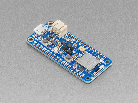
The Adafruit Feather Bluefruit Sense takes our popular Feather nRF52840 Express and adds a smorgasbord of sensors to make a great wireless sensor platform. This Feather microcontroller comes ...
Btw I found this but not sure if there is anything else I have to do
https://docs.zephyrproject.org/latest/boards/adafruit/feather_nrf52840/doc/index.html
red panther
dull lodge
Hi I’m planning to learn basic zephyr but never used nordics official sdk. Only ...
I don't understand your question. You have the hardware, you found the documentation. What do you need?
dull lodge
If the zephyr is directly usable of feather sense or do I need some firmware/bios change. Thanks for looking into it
red panther
dull lodge
If the zephyr is directly usable of feather sense or do I need some firmware/bio...
Never tried it. Are you running into issues?
I don't have that hardware at my desk and I can't try it on your behalf
But there is no BIOS and the firmware is the operating system + application. So I still don't understand your question.
By the way, there are 138 nrf52840 boards supported by Zephyr. If any of them are actively maintained, then the Bluefruit will probably still work.
Probably only the Adafruit ones will support the UF2 (usb) programming method, but a UF2 can be created from a Hex or Bin file if needed
 brisk rain
dull lodge
If the zephyr is directly usable of feather sense or do I need some firmware/bio...
brisk rain
dull lodge
If the zephyr is directly usable of feather sense or do I need some firmware/bio...
zephyr is the firmware so yes, you'll need to flash it
 sage yarrow
Hello!
Saw the recent blog post about the TCS3448 from ams-OSRAM.
I'm building a wearable health light monitor and the TCS3448 seems ideal: passive ambient sensing, lower power, same driver as the AS7343.
Any timeline on a breakout board? Happy to beta test if helpful. Was thinking of running the TCS3448/AS7343 breakout running on a Feather nRF52840 and TCS3448 seems better than AS7343 for this use case.
 willow scaffold
Assuming I place factory fresh components on my own PCB to replicate the functionality of an AudioFX board, what state would the VS1000 and memory chip be in? Can I just pull GPIO6 low and drop a .bin file onto the memory right away or are there other requirements? There's a forum thread on this linked in the tutorial where someone's using something like an FTDI friend (which I don't have) and there's mention of formatting and writing disk images, but I'm not sure if that's all just related to faulty units.
 wooden pecan
Hey! 👋
We’re a high school team from Al-Ola Secondary School in Jubail 🇸🇦 competing in WRO 2026. We’re starting from scratch with Raspberry Pi 5 and would love to learn how to set up and assemble the components the right way.
Would love to meet up and learn from you! Even a short session would be awesome 🙌
— Al-Ola Team, coached by Mr. Badr
red panther
Saudi Arabia? Cool. I don’t know if anyone here has WRO experience though. I did FRC.
inland summit
When making light pipes for multiple leds, do you need a separate piece for each light or can it all be connected
 gloomy portal
@inland summit - I made a little 3DP lightpipe for the Fruit Jam last year. It was a single print with multiple holes. I made sure to use black PLA. There was a bleed trough with the default case that did not have any separation between LEDs.
abstract vault
SINCE NO ONE HELPED BEST WAY TO LEARN KINEMATICS FOR REAL IS TO WATCH STATICS THEN DYNAMICS THEN KINEMATICS FULL FREE ONLINE COURSE FROM UNIVERSITY PROFESSOR JEFF HANSON HE TEACHERS BASICS TO ADVANCED THINNGS EVERYTHING YOU GOTTA KNOW
red panther
Ok. Hope you figure it out
 fading cove
what lmao
red panther
I think he was asking for help with six-axis kinematics. I sent a resource that was a little too advanced because I assumed he was comfortable with calculus.
fading cove
Ahhh
warm jay
Question:
Assuming I have an ESP32 board
How can I set it up in a way that I can send code to it over wifi? (Like a firmware update from my PC or phone)
And how can I set it up in a way that it automatically downloads an update from github for example?
red panther
There’s the circuitpython web workflow. I think you could write something to periodically check for updates on github and download them.
ESP-IDF may also have its own OTA update mechanism
cunning saffron
In CircuitPython, there is dualbank https://docs.circuitpython.org/en/latest/shared-bindings/dualbank/index.html but I think it's no longer included in builds by default. For code (but not firmware) in CircuitPython, there is https://docs.circuitpython.org/en/latest/shared-bindings/supervisor/index.html#supervisor.set_next_code_file and other tools that let you change the code that's running.
buoyant jackal
warm jay
Question:
Assuming I have an ESP32 board
How can I set it up in a way that I ca...
is it circuitpython you want to use, or something else?
inland summit
Ok. Need some logical support. If I'm trying to make a self centering clamp for a 3d scanner, then the easiest way to do it would be to have the prongs that secure the piece essentially measure the distance between themselves & center & self adjust till the measurement is even. This works on consistently sized objects such as a ball. But how would I do inconsistency shaped objects like an n64 controller?
I suppose if I can center one direction I can center the others, the issue ultimately finding rotational center right?
inland summit
& will timenof flight sensors work as a scanner?
red panther
What does “centering” even mean for a N64 controller? Do you need it centered because you’re near the dimension limits of your scanner?
In woodworking, self-centering jigs really only apply to round objects
inland summit
red panther
What does “centering” even mean for a N64 controller? Do you need it centered be...
I plan of having the sensor sweep back & forth on the x & y axis, the part will rotate 90° on the x axis, repeat sweep, the part will rotate again, ect. Then another set of arm will grab the part & repeat the process but rotate on the y axis. I need the part to not move between arm switches.
inland summit
Basically if this is an n64 controller I need to find rotational center (which is @ the yellow dot. To find it i need the machine to ensure that when it rotates along the x axis points a & b are the same distance from the sensor. Same for if it rotates around the y but with c & d
 sage moth
my partner and their caretaker want to find a watch pair that can communicate a need by my partner to their caretaker via radio like a lora packet, I'm thinking an ESP32 based radio solution but I don't know any that would be viable short of bolting together a couple dev kits in a barely functional way
red panther
ESP32 has their own long-range radio solution. What do you need for range, data rate, battery life?
sage moth
I don't know desired range, espnow may work, current system is a key finder from Samsung notifying the caretaker's phone
also, no idea what I said wrong, but automod refused to let me say that at first
bold hollow
Nevermind thought of reasons
inland summit
In this part, when it says .1 spacing it means space between the contacts edges, not their centers right?

If you love power adapters or toys & gadgets that have magnetic connections, you can now experiment with these futuristic connectors easily. It's sorta like a DIY ...
bold hollow
if you peep the datasheet it has the dimensional drawings

(its in mm but 2.5mm is about 0.1 inches)
so according to this its 0.1 inch pitch between centers
is that what you meant?
inland summit
Ah. I see. I tend to work in mm for more divisible precision so I read it as .1mm not .1 inch
ᚦank you
Im currently trying to add a 3d model to a fusion library component & its not working
inland summit
So, I need some help. Im thinking about putting charge boards into a power cord. The cord then connects to a pico & charges the battery. The problem im having is how to connect the battery to the pico. Do I connect the charge connector to the battery first?
 woven frigate
I would imagine this is where a project gets a little hairy. Any advice or fun stories?
 woven frigate
just powering a bluetooth keyboard im at least addin a disconnect switch. i didnt know if there was ought else to do
bold hollow
Is this a kit or something?
woven frigate
oh no. lol i am building it myself(based on the Dactyl Cygnus guide) it going to supply a pro micro nrf52480. https://www.youtube.com/watch?v=h_ex-oMVOrI&t=59s
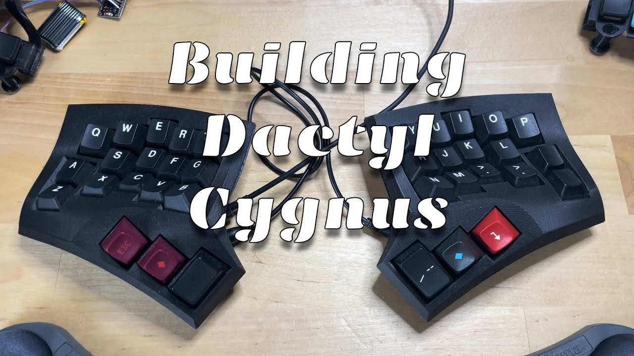
This is a video about building a 3D printed split keyboard that I've designed.
Detailed build guide here: https://github.com/juhakaup/keyboards/tree/main/Cygnus v1.0
Music by CreatorMix.com
bold hollow
If it has built in lipo charging then just dont put it in rhe wrong way and you'll be fine, probably
woven frigate
I checked/forgot/checked again, the polarity like 4 times. I ended up labelling it as "checked"
woven frigate
So when the battery is connected and it's plugged into USB. I get a solid blue light and no red light. Not sure if it's a bad thing or a zmk firmware thing.
The reset button works and puts it in bootloader mode and vice versa. So I'm pretty sure it's working right. I just need to finish configuring ZMK
 white marsh
woven frigate
So when the battery is connected and it's plugged into USB. I get a solid blue l...
white marsh
woven frigate
So when the battery is connected and it's plugged into USB. I get a solid blue l...
What shows a blue light? Whatever you are using for a charger?
woven frigate
Yeah my controller. Pro Micro nRF 52840
 white marsh
woven frigate
Yeah my controller. Pro Micro nRF 52840
white marsh
woven frigate
Yeah my controller. Pro Micro nRF 52840
Oh I see. Does it have a lipo charger built in or do you have a seperate charger?
woven frigate
it has a built in charger
I read a few things about versions of it. i think its working normally lol
white marsh
woven frigate
it has a built in charger
Then hopefully all is well, which of course you won't find out until you get it all put together and THEN discover you forgot something, didn't hook up something, etc.
inland summit
In the pico w, what is part L1 in the power chain
 bold hollow
inductor
 shrewd breach
I’d assume a 1 uH inductor
bold hollow
thats the buck/boost converter so yeah makes sense, im not any good with circuits though
 drowsy drift
Anyone here experimented with NAU7802 and weight drifting over time. For example over 40 minutes, they weight augmented ~3g
red panther
drowsy drift
Anyone here experimented with NAU7802 and weight drifting over time. For example...
That’s pretty common with scales, thus the tare before weighing. Temperature is usually the culprit
You might be able to calibrate on the fly with a crossbar switch
inland summit
Im designing an rp2040 (pico w specifically) based board & am using this (https://www.adafruit.com/product/2124) to power/charge it. The problem is, with the design im doing the leds overlap with the ones from the pico. How would I route the signal those leds flash through the pico circuitry & out to a single led
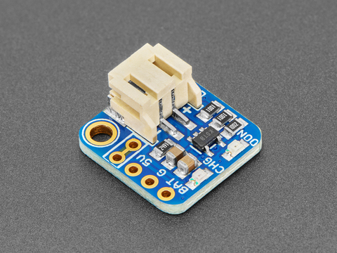
If you have an ItsyBitsy or Pro Trinket you probably know it's the perfect little size for a portable project. This LiPoly backpack makes it really easy to do! Instead of wiring 2 or 3 ...
inland summit
Im trying to revise my rumble pack Bluetooth adaptor for the n64/switch & need some reminders/logic help. If I remember my first attempt to wire the rumble motor directly into the pico it caused nothing to work cause of power draw. So when I revisited ᚦe project, I was going to wire the pico & the rumble feature separately. Thats fine & all for a project built with pre-made breakouts & whatnot. But with a self designed board, I should be able to fix that issue altogether. The issue im having is i dont know how. Any ideas?
Im using the pico w, the charge board from above, som3 custom parts, the circuits from the rumble pak im cannibalizing (currently, can change if needed) & this motor (https://www.adafruit.com/product/1201). For batteries i have a pair of 3v lithium ion batteries that are in a aaa battery form.
bold hollow
Im not the best to answer this but usually you would need some method to feed more power to the motor, the pico itself can only put out like 30ma? i think on the GPIO, though the 3v3 rail can put out 300ma max, looks like the lil buzzy motor would draw 60 ish at 3v3, so you could connect it to the 3v3 rail and use a transistor
the webpage mentions using a pn2222 transistor
inland summit
bold hollow
the webpage mentions using a pn2222 transistor
If im understanding it correctly, a diode, a resistor, & a transistor all walk into a bar & start a buzz. While it is set up in ᚦe tutorial as arduino, it should work wiᚦ rp2040.
The big issue is the n64 edge connector would be useless
bold hollow
why is that an issue?
inland summit
Cause the code im using sends the signal for the rumble through the controller. I dont know c++ well enough to change it to a pin.
bold hollow
I think people will struggle to help you without more of an idea what you are doing and what you are using
inland summit
I'll make a list of parts & link ᚦe original project
inland summit
bold hollow
I think people will struggle to help you without more of an idea what you are do...
Ok. This is the project: https://github.com/DavidPagels/retro-pico-switch
Here are the boards that im using the schematics to create my board:
Magnetic connector for charging & data (https://www.adafruit.com/product/5358)
Pico w for the brains (https://www.adafruit.com/product/5526)
Trinket charge board for charging (https://www.adafruit.com/product/2124)
This for the motor (https://www.adafruit.com/product/1201)
Aaa style lithium ions for power (https://www.digikey.com/en/products/detail/pkcell/ICR10440-350-B/12354031)
& a Chinese knock off rumble pak that I dont have a link for. Maybe swap it for a haptic motor controller if I absolutely need to (https://www.adafruit.com/product/2305)
Custom parts are the rumble edge pins on a shaped board, & a custom socket footprint.
Including rumble pack circuit board pics



GitHub
Play Nintendo Switch Online N64 games using an Original N64 controller via a Raspberry Pi Pico! - DavidPagels/retro-pico-switch
If you love power adapters or toys & gadgets that have magnetic connections, you can now experiment with these futuristic connectors easily. It's sorta like a DIY ...
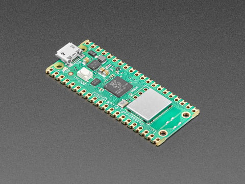
The Raspberry Pi foundation changed single-board computing when they released the Raspberry Pi computer, now they're ready to do the same for microcontrollers with the release of the ...
If you have an ItsyBitsy or Pro Trinket you probably know it's the perfect little size for a portable project. This LiPoly backpack makes it really easy to do! Instead of wiring 2 or 3 ...

BZZZZZZZZZZ Feel that? That's your little buzzing motor, and for any haptic feedback project you'll want to pick up a few of them. These vibe motors are tiny discs, completely ...
The plan is to basically wire them together, strip out the unneeded, & throw it onto a board powered by the 2 rechargeable aaa. The device slots into the n64, the controller plugs into the socket, then the device connects to the switch. Wireless connection without removing the cable from the controller
 vague tulip
Is there anyone looking for a developer?
inland summit
bold hollow
Im not the best to answer this but usually you would need some method to feed mo...
you said you can draw 300ma from the 3v3 rail. does that mean that if i wire the rumble pack circuits to draw power from the 3v3 pin, it should work fine??

Somewhat like this
Minus ᚦe second charge board
bold hollow
It depends how much the rumble pack draws, but from a power standpoint, probably fine???
if you knew how much power your rumble pack draws you would get a better idea
inland summit
i do not. i might be able to get the originals details but probably not this ones
inland summit
bold hollow
if you knew how much power your rumble pack draws you would get a better idea
ok. so, the og ran on aaa batteries and had a playtime of roughly 15-20 hours. im assuming thats with a constant rumble signal being sent. the battery free mod allowed it to run off the 3v3 line from the console but limited you to only 2 of the modded rumblers at a time. the replacement motor im using draws 60 ma and the pico delivers 300ma so whatever the draw is from the circuit needs to be somewhere between those two numbers right?
aaa batteries are rates at 750-1000mah and are wired in series making them roughly 6v. but if the pack can run on 3v3 then the 6v must only be used when the motor goes off and the circuit itself sits at 3v3 watching for the signal
bold hollow
If i was to guess i would say you could probably power it from the 3v3, but it would be a guess, you could use a multimeter to check power draw if the board works tho
inland summit
im not sure on the matvch but if it takes 1 hour to drain 750 ma, but the pack runs at 15 hous, would it be 750/15?
i messed up. the batteries supply 3 v not 6
and i changed my search. it says 300-500 ma draw
but it also says the original rumble lasted 50-60 hours
ok. i think i found it..2a -.3 a when motor activates. that means it hits 300ma at most. it also means that the circuit doesnt draw that much normally so replacing the motor not only allows me to fit more in the shell. but that the motor shouldnt hit highter than 60
and the circuit is basically asleep til the controller wakes it up
if the motor is removed thy circuit runs 5-15 ma when it receives the rumble signal
this means my board, with the single haptic motor runs atr roughly 0ma when idle and 5-60 ma when active
sorry about all the messages, i was working through the problem. i can delete most of them if yall want
my final conclusion is: with the pico allowing 3v3 at 300 mah, the rumbler im making would only need 0-3v at 0-60 ma to operate, micro controller, controller, and blue not included
the controller itself draws up to 30 ma itself, bringing me to a requirement of 3v at 90 ma
the pico itself apparently draws 150 ma when bt is avtive.so the whole rig should pull 240 ma at max. if i did me maths and research right.
as a final thought. i could wire it so the power from the batteries goes into the controller which then supplies the pico and rumble pak circuits with power. the only circuitry i need to connect to the battery would be the 3v3 and ground pins from the socket and a charger board to charge the batteries. the data pin from the socket would be the only pin id have to connect to the rumbler and pico circuits and thats a single line to pin 18. does this sound right to anyone else?
 lapis rock
Anyone know of the standard way to charge many AA 1.2V 2800mAH NiMH batteries at once? I need to charge a couple hundred of them and the smart chargers I'm seeing online are mostly for 8 cells at a time (and a scarce few 24 at a time, but they are quite pricey!). If there's a nice drop-in product that just works that would be great, if not, any ideas on what a good charging regulator board would be is appreciated! I could just make my own massive charging station with many regulator boards.
inland summit
lapis rock
Anyone know of the standard way to charge many AA 1.2V 2800mAH NiMH batteries at...
i think this belongs in gen chat but i did find this for you https://www.amazon.com/BONAI-Rechargeable-Batteries-Independent-Standard/dp/B09NW28R66/ref=sr_1_8?crid=NC19KREOKBR3&dib=eyJ2IjoiMSJ9.ktyGYsdHXWA1uiWPyRykgAg5iVPlEF24R99sUjk2Za0dPW9GW14GBE19IhP0MfigNyaf8fUf2kzf-orIuHzZLguVXxaPS-afZathIntvZGORXz9wWBDCpWP_nDZGhfYg6z2pahP-unWp--m82G4vkOyc7XT1N8r_XjtCXVASaNNp6QtKMN4bhHJmoDqOIk5FRJp6sbEbwP-7cP1fiwGYGW9x6Adk8NQlr_YXbya-mqg.vJ8HfWIUDYBWtxET4tULeBSPwd-I4r61rWEQlJCR6eM&dib_tag=se&keywords=aa%2Bbattery%2Bcharger&qid=1779809333&sprefix=aabattery%2Bcharger%2Caps%2C157&sr=8-8&th=1

BONAI AA AAA Battery Charger 16 Bay for NiMH Rechargeable Batteries Independent Control with LED Light and Standard American AC Charging Plug, Battery not Included - Black
inland summit
lapis rock
Anyone know of the standard way to charge many AA 1.2V 2800mAH NiMH batteries at...

MIEKLALE 20+2 Bay AA AAA Battery Charger with Smart LCD Display Fast Charging for AA AAA NiMH NiCd & 9V Rechargeable Batteries, 2 Separate Charging Slot for 9V Batteries
lapis rock
gah, looks like my search abilities are quite mediocre. $36 for 20 is a lot better than the $70 24 cell ones I found
thanks!
inland summit
np.
inland summit
can the blue line be removed without compromising the power chain
