#help-with-projects
1 messages · Page 4 of 1
 cloud acorn
Eh, I did more desoldering last night than I thought I did, so it doesn't look like anything except messy solder and flux. I am going to try again tonight and grab a picture
 lethal prairie
I'm using the st7789 rounded rectangle display in a project and getting a fair amount of tearing. Wondering if there is an available display that exposes the TE tearing effect line. The only display could find from adafruit with the TE line broken out was out of stock
 buoyant jackal
The https://learn.adafruit.com/neotrellis-soundboard/ uses a 4x4 NeoTrellis standalone keyboard, and separate parts for the micocontroller board and the audio output board ("Prop-Maker"). The https://littlebirdelectronics.com.au/products/adafruit-neotrellis-m4-with-enclosure-and-buttons-kit-pack is a different thing and later thing: it is an 8x4 keyboard with a microcontroller (and other things) on board. It would be possible to duplicate the project with that, by making some code changes.
 blazing vortex
buoyant jackal
The <https://learn.adafruit.com/neotrellis-soundboard/> uses a 4x4 NeoTrellis st...
blazing vortex
buoyant jackal
The <https://learn.adafruit.com/neotrellis-soundboard/> uses a 4x4 NeoTrellis st...
Thank you
 silent thicket
Hey folks, less a project question and more searching for tips n tricks
When it comes to soldering single ended LED filament, anyone have advice on getting good clean connections? I've been able to do it but keeping those little contacts from shorting is a real bear
blazing vortex
Looking at what I was earlier, appears this is the only stand alone solution which plays media onboard which you can then edit/change. https://learn.adafruit.com/neotrellis-soundboard/featured_products
buoyant jackal
silent thicket
Hey folks, less a project question and more searching for tips n tricks
When it ...
I'd try putting some cardboard or folded paper or similar something between the prongs, so the solder cannot jump the gap.
buoyant jackal
silent thicket
Hey folks, less a project question and more searching for tips n tricks
When it ...
Maybe you could find something less flammable, but if your soldering is quick I think it will do no more that scorch slightly. Solder does not stick well to aluminum foil, but that will also conduct heat away.
 stiff scroll
Are there any good resources for driving multiple small oled displays? I'm curious about best practices on the hardware and software side - mainly interested in creating interfaces similar to a lot of digital synthesizers that have individual displays for parameters and such
 willow badge
Hi! I'm working on a project where I'd like to make a circuit to have a momentary switch behave like a latching switch. I have found a couple of example circuits that use inverters (or NAND gates with inputs wired together) to achieve this. However, the city I live in does not have an electronics parts store so I have been trying to mock up my circuit in tina-ti to make sure it works and what components I need before I order the components. The issue I have is with the syntax(?) of mocking up the circuit -- I can make something that looks right, but the DC voltage reader just returns an error. I know it's somewhat software-specific, is that something I can still get help with here? Is there a different simulation software I should be using instead? Thanks!
 red panther
willow badge
Hi! I'm working on a project where I'd like to make a circuit to have a momentar...
red panther
willow badge
Hi! I'm working on a project where I'd like to make a circuit to have a momentar...
What do you have to work with? Relays? BJT transistor? I’ve never used tina-ti, but Falstad isn’t bad for simple things
 fleet terrace
stiff scroll
Are there any good resources for driving multiple small oled displays? I'm curi...
fleet terrace
stiff scroll
Are there any good resources for driving multiple small oled displays? I'm curi...
Depends on how many and big each is. I2C might not be suitable since you might need 1 bus per display. Parallel or SPI driven displays might be possible but will depend on IO pins available.
red panther
Are SPI OLED displays common? The cheap two-color ones I’ve seen are all I2C. They do make such a thing as an I2C mux, if you’re ok with the slowdown of multiplexing four displays on a single bus.
buoyant jackal
red panther
Are SPI OLED displays common? The cheap two-color ones I’ve seen are all I2C. Th...
The SSD1306 and SH1107 driver chips for OLED displays can be I2C or SPI (some chips also do 8-bit parallel, but we don't break out all those pins).
cloud acorn
Is it possible to to use one of these terminal blocks - https://www.adafruit.com/product/725 in place of a USB A on the powerboost 1000C - https://www.adafruit.com/product/2465 for a project with addressable LEDs? the USB A male and female sides are taking up too much room in the project, so I'd like to try to slim down the connection. Im just not sure if its possible.

Nothing makes a project harder to maintain than a lot of loose wiring. That's why we like to use terminal blocks whenever making PCB-to-Wire connections. These particular 3.5mm terminal ...

PowerBoost 1000C is the perfect power supply for your portable project! With a built-in load-sharing battery charger circuit, you'll be able to keep your power-hungry project ...
buoyant jackal
cloud acorn
Is it possible to to use one of these terminal blocks - https://www.adafruit.com...
The holes on the long edge of the board are spaced at 0.1". You can use these, maybe in combination: https://www.adafruit.com/search?q=0.1+pitch+terminal+blocks
the ones you pointed to have wider spacing
cloud acorn
buoyant jackal
the ones you pointed to have wider spacing
Thank you! Is there any resource or a guide on where these connect in place of USB? Since it looks like the pins don't connect the same way as USB does. This is my first time working with a PCB and soldering anything, sorry if it's not as obvious to me as it should be, still learning.
buoyant jackal
cloud acorn
Thank you! Is there any resource or a guide on where these connect in place of U...
See the schematic here: https://learn.adafruit.com/adafruit-powerboost-1000c-load-share-usb-charge-boost/downloads
and the pinouts page here:
https://learn.adafruit.com/adafruit-powerboost-1000c-load-share-usb-charge-boost/pinouts
The schematic shows that the USB connectors are connected to some of the same pins as the 8 pins in a row on the long edge of the board (and also the JST battery connector)
you could just solder to the pin holes, but using screw terminals makes for better maintainability
read our guides on soldering if you have not done so yet
use solder for electronic purposes. DON'T use plumbing solder
cloud acorn
I actually did use some of your guides on soldering, and had some success with soldering the USB to the PB1000C, it was my first time soldering, thanks for that! It looks like I might have to do a little more research on this, it's a little foreign to me but I can probably figure it out 🙂
trying to figure out a schematic for a brand new maker like myself is a little intimidating
buoyant jackal
cloud acorn
I actually did use some of your guides on soldering, and had some success with s...
in the schematic all the places with the same name are connected together (like "5.0V" or "GND"). You can click on the schematic and then view a bigger versino.
willow badge
red panther
What do you have to work with? Relays? BJT transistor? I’ve never used tina-ti, ...
Hi, sorry for the late reply. It's just some inverters and capacitors, and a transistor on the output. Here are the circuits I'm basing it off of. It may be that I just don't understand how simulating this kind of circuit works, but it seems like there's nowhere to put vcc when simulating it, other than on the chip vcc itself which there isn't an input for in the simulator? Same in Falstad from what I can tell. Am I just going about the simulation in the wrong way?


 tacit vessel
hi! i was wondering if anyone here is familiar with touch designer. I am currently taking an intro class at uni that centers our curriculum around touch designer. I had an idea for a project that uses ardunio with touch designer but I am not exactly sure how to combine the two. I want to use the webcam input feed as an sensor that detects where a person is standing on an x,y axis and then sends that data to the arduino. The ardunio will then control two servos that move 3d printed eyes in the person's general direction.
I've watched a few youtube videos on getting ardunio connected to touch designer using the serial port but I am still unfamilar with touchdesigner and my prof doesn't know much about ardunio
red panther
willow badge
Hi, sorry for the late reply. It's just some inverters and capacitors, and a tra...
Share a timyurl link to your falstad circuit and I’ll try it out
willow badge
red panther
Share a timyurl link to your falstad circuit and I’ll try it out
https://tinyurl.com/3a2pwczz Here I have clearly done something wrong on the output where I was just trying to have some sort of transistor output, but this is the circuit I think.
red panther
Button toggle latch
 static mist
What is the most straightforward hardware configuration to stream video over wifi with an esp32-s3? One of the OV5640 Camera Breakouts? Would it be better to get a raspi camera module and get a pico or zero instead?
red panther
I haven't tried the ESP-CAM yet. I wouldn't expect the ESP32 to support h264, but some cameras provide the image already in jpeg so you could stream it as mjpeg pretty naturally
I wonder if any of the ESP-CAMs take external antennas? This would greatly simplify my submarine project. EDIT: yes they do https://randomnerdtutorials.com/esp32-cam-connect-external-antenna/
This might be helpful https://www.youtube.com/watch?v=BCvOBMQSliY

How about using a lens other than OV2640 on ESP32?
This is today's hero, OV5640. Because it has a 1/4-inch 5-megapixel CMOS image sensor, it's possible to acquire images of up to 2592x1944.
In today's video, I'm gonna connect this OV5640 to the ESP32 AI-Thinker board and show you how it works.
Please Note
Each manufacturer of OV5640 has sli...
The frame rate test was surprising. It could be that the OV2640 uses a higher compression of JPEG and thus smaller files are being transferred.
static mist
red panther
This might be helpful https://www.youtube.com/watch?v=BCvOBMQSliY
Very helpful thanks!
 upper bloom
willow badge
Hi, sorry for the late reply. It's just some inverters and capacitors, and a tra...
upper bloom
willow badge
Hi, sorry for the late reply. It's just some inverters and capacitors, and a tra...
Falstad does not have pins for logic voltage on their logic gates, but you can adjust the logic voltage by right clicking the component and select “Edit…”
 remote raft
Is there anyway to have the dome cover to sync the parallel motion linkage motion?
I have a single micro servo that drives the plate.
When the top plate moves up I'd like it the cover to open, and when it closes, it should also close.
I have placed 3 rods, 2 on the moving pivot points for the plate and 1 on the bottom.


 red panther
remote raft
Is there anyway to have the dome cover to sync the parallel motion linkage motio...
red panther
remote raft
Is there anyway to have the dome cover to sync the parallel motion linkage motio...
So you want rotation in opposite directions. Yes, there are mechanisms to do this. The most common is a gear, but in your instance I suspect you’d prefer a crossed four-bar linkage
Another gear alternative is the crossed belt
remote raft
Do I have to change my parallel 4 bar to crossed then?
red panther
remote raft
Do I have to change my parallel 4 bar to crossed then?
No, this is in addition to it
Though you might not like the space constraints
Do you have Lego technics or an erector set or something you can model with?
remote raft
Yea was always concerned about the limited space.
No I don't have any of that. This one was first modeled by printer paper I shaped and taped up.
red panther
Hmm. That makes it harder. Printer paper doesn’t do well in compression. Something stiffer like cardstock or cereal box cardboard would be better
remote raft
I have cardboard boxes laying around that I use
red panther
Go ahead and try some things. It could be that a single linkage from the plate to the lid is sufficient
In my mind it seems to bind when the lid is all the way down
remote raft
Thought I had cardboard boxes but all of them are used up. I guess I'll make do with the printer paper then until I find something else
remote raft
red panther
In my mind it seems to bind when the lid is all the way down
I was thinking of using a spring to push/pull the cover but I did not think it through as I thought it didn't make sense but I'll show what I drew anyway.
 red panther
remote raft
I was thinking of using a spring to push/pull the cover but I did not think it t...
red panther
remote raft
I was thinking of using a spring to push/pull the cover but I did not think it t...
Yeah, a soft coupling makes sense. Are you going to add a string so it pulls the cover back down?
remote raft
red panther
Yeah, a soft coupling makes sense. Are you going to add a string so it pulls the...
I think I can use a fishing line. Where should I place the string?
red panther
remote raft
I think I can use a fishing line. Where should I place the string?
You’ll have to experiment. Tack it on with duct tape so you can try different locations
 ebon apex
No, it was connected directly to the primary pcb :/
remote raft
red panther
You’ll have to experiment. Tack it on with duct tape so you can try different lo...
Thanks for helping. Added an extra servo to make things easier
red panther
Nice work!
 humble sinew
I'm using a TIP120 transistor to switch a 12V 500mA light strip on and off. it gets super hot and I'm worried I'm going to burn my house down... Is something wrong or is this normal?
It fades in and out with PWM, connected to my ItsyBitsy with a 1k resistor.
buoyant jackal
humble sinew
I'm using a TIP120 transistor to switch a 12V 500mA light strip on and off. it g...
could you show the schematic? It may well need a heatsink
a MOSFET would be a better choice: https://usa.yamaha.com/products/musical_instruments/guitars_basses/ac_guitars/fg_series/fg_800/specs.html
a MOSFET would be a better choice: https://forum.arduino.cc/t/tip120-super-hot/442673
 slender tendon
what's the simplest available off-the-shelf chip/breakout to drive a common 12v or 24v LED strip from a microcontroller? I didn't know the exact power requirements yet, but need relatively diffuse light intensity comparable to full daylight within an enclosure with volume around a cubic foot and dimming either manually with PWM or via variable current
I'm looking at this driver, but wondering if there's something similar that will take 12v or 24v directly
buoyant jackal
slender tendon
I'm looking at [this driver](https://www.adafruit.com/product/6354), but wonderi...
how about https://www.adafruit.com/product/5888

Whenever we're working with 'true analog' LED strips, that have 1-3 channels of RGB or White LEDs, we wish we had already invented to make wiring them easier: ...
slender tendon
buoyant jackal
how about https://www.adafruit.com/product/5888
looks good to me
 unborn grotto
quick question, but is this totally busted? :( i wanted to see if id be able to fix this before having to buy a new one, does anyone know if thats possible?
 buoyant jackal
unborn grotto
quick question, but is this totally busted? :( i wanted to see if id be able to ...
buoyant jackal
unborn grotto
quick question, but is this totally busted? :( i wanted to see if id be able to ...
This is much more likely to be a software, settings, or wiring problem
unborn grotto
hmm, would you be able to elaborate a bit more on that? i don't see how it could be the first two so it might be a wiring issue
it was working fine earlier last week but i installed it in a cosplay i had spraypainted earlier on tuesday, i thought it would be ok to put it in on friday, but when i came back home it started doing this when i plugged it back in
buoyant jackal
Eating… I’ll be back. List the exact part numbers and what software you are using
unborn grotto
i hope the fumes didnt damage it permanently 😞
yeah of course 🙏
i hope im doing this right
parts:
- 64x64 RGB LED Matrix - 3mm Pitch - 192mm x 192mm
- Adafruit Matrix Portal M4 - CircuitPython Powered Internet Display (parts are in screenshot below)
software: - circuitpython

 molten iris
unborn grotto
i hope im doing this right
parts:
- 64x64 RGB LED Matrix - 3mm Pitch - 192mm x 1...
molten iris
unborn grotto
i hope im doing this right
parts:
- 64x64 RGB LED Matrix - 3mm Pitch - 192mm x 1...
And you soldered the jumper on the MatrixPortal so it can do 64x64?
unborn grotto
yes!
molten iris
are you powering the matrix from the MatrixPortal or do you have a separate power supply (which I would recommend)?
unborn grotto
i have a separate power supply
molten iris
well shoot, those were my guesses
molten iris
that would be my guess if it was working before
unborn grotto
bummer, ill have to get a new one before friday at least
i thought id be able to fix it
buoyant jackal
unborn grotto
it was working fine earlier last week but i installed it in a cosplay i had spra...
Did you disassemble it to install and uninstall it? Could be a loose connection. Are those multiple panels? If so check the jumpers between the panels. Is the Matrix Portal plugged into the exact same place as before, and is it well seated?
a back photo might help
you said fumes, but were they that strong? this seems more like a mechanical issue
unborn grotto
buoyant jackal
Did you disassemble it to install and uninstall it? Could be a loose connection....
i had to remove the matrixportal and cables but that was the extent of it
ill get some good pictures
heres the back of the led panel and some pictures of my mateixportal m4


 buoyant jackal
did you put the Matrixportal and the power cables on the exact same connectors as before?
do you have a voltmeter so you can check the external power supply?
the fact you are only seeing red could be because of sagging voltage, because the red LED's require the lowest voltage
so you are powering this entirely from USB?
when it was working before, how were you powering it?
unborn grotto
i believe i did? im using all the same stuff
i think the power bank is the issue actually. i'm going to try plugging it in directly
buoyant jackal
so the only power connection is through USB? Is the power bank a USB power pack?
unborn grotto
yeah to both of those
buoyant jackal
do you have a hefty USB AC adapter you could try instead for debugging?
the screw terminals are tightened nicely, right?
unborn grotto
yes they are!
unborn grotto
i just plugged it into the outlet and it seems to be working fine now, i think the portable charger i had just wasnt doing it for me
also checked the cables and it was likely just me not plugging it in properly 😵💫 😵💫 sorry for the trouble!!
buoyant jackal
it's a learning experience 🙂
unborn grotto
that malfunction scared the daylights out of me since i have a con in a few days hahaha
i really appreciate you trying to help me troubleshoot that! im learning a lot even from your questions 🙏 thank you so much for your time
buoyant jackal
you're welcome!
 abstract vault
Hello im new here, i am working on a 6axis robot arm. I am currently working on it and building it. But i cant move on rn since i have to wait for parts toarrive. So i was wondering if anyone could help me with Foward and Inverse Kinematics. Also about how to account for backlash with and without load, think its called Linear algebra? Also about Kinematic Chain, Kinematic Singularity and Computational geometry. These sound complex and complicated to implement. Am i overthinking these things? Can someone help me?
red panther
Kinematics can be complicated, especially depending on your mechanism. I would be surprised if you can estimate backlash without the physical robot, since backlash will change as the gears wear out.
This looks like a good source https://automaticaddison.com/the-ultimate-guide-to-inverse-kinematics-for-6dof-robot-arms/
 abstract vault
Thanks!


 abstract vault
Wat is thisss is this 
Linear Algebra?
Trigonometry
Geometry???
 mighty walrus
red panther
mighty walrus
red panther
Sorry. I thought you knew you were getting into some heavy math
red panther
abstract vault
Wat is thisss is this <:blinka:342384086444146718>
Linear Algebra?
Trigonometry...
All of the above
But you asked about backlash under load, which means you’ll also be doing differential calculus
red panther
I’ve never done six-axis kinematics, but I’m doing 2-axis kinematics right now for a weird little linear actuator at work.
Sympy is pretty great for my application: it can solve equations symbolically (and their inverse!!) and then convert it to numpy functions.
The hard part was in path planning: there may be multiple ways to reach a given position, and you need to decide which to use.
abstract vault
red panther
Sorry. I thought you knew you were getting into some heavy math
Im only a student 😭 not even university
Tho i am learing about th three topics tho and 3d matrix etc
Its complicated only if you cant visualize it i would say
im only 17 :/
abstract vault
Alr so i am just gonna use a liberary to make it easier
 tight stirrup
Hey guys I was looking to code a simple usb macro for my Nintendo switch and was wondering on what library I should be using?
molten iris
tight stirrup
Hey guys I was looking to code a simple usb macro for my Nintendo switch and was...
Are you looking to use a microcontroller to send the USB signals? If so, check out GP2040-CE, more at Adafruit Learn: https://learn.adafruit.com/pokemon-macro-ball-for-nintendo-switch/install-firmware-and-customize-settings
 hollow obsidian
@woven anchor Hello there. I have a question in regards to the analog clock project here: https://github.com/adafruit/Adafruit_CircuitPython_Display_AnalogClock What is the tool you used to make the hour and minutes hands? I want to make a seconds hand. So I copied the minutes hand cropped the arrow off and colored it red. It did not work out as I expect. It floated around the outer edge of the clock dial. claude helped me discover that the BMP files rotate vs a sprite moving sort of thing. I guess I need to get my hands on the tool you used to create a proper seconds hand. 😛
GitHub
Draw a traditional 12-hour analog clock face with hour and minute hands. Allows you to provide graphics to customize the clock. - adafruit/Adafruit_CircuitPython_Display_AnalogClock
 oblique bone
Hey friends. I'm working on figuring out what components I need for my next project and just wanted to get a sanity check on the design. The goal is super simple on the surface. Boot when receiving power, light LEDs on boot, and play a sound file on boot. It's going to be housed inside a bracer on my wrist with a membrane button feeding down to my palm. Sort of like a Spider-Man web shooter in a way. I'll want the controller to only receive power when I hold that button. Would a small form factor raspberry pi be best for something like this? I noticed that they have boot buttons which tells me they won't auto boot when receiving power. I'd be happy to be wrong in that regard though

Ps sorry for my handwriting. I also realized after sending this that the amp probably needs battery power too
 woven anchor
hollow obsidian
<@382939733107408897> Hello there. I have a question in regards to the analog c...
woven anchor
hollow obsidian
<@382939733107408897> Hello there. I have a question in regards to the analog c...
I believe the hands were created in GIMP, but any image editing software that can preserve the palette should work fine I think. I'm not sure if I'm understanding what you tried perfectly or not, if you can post the image you ended up with for the second hand here it would help confirm my understanding.
Generally I think it should work to make a new hand image and add the angle calculation and additional rotozoom() call for it inside of set_time().
tight stirrup
molten iris
Are you looking to use a microcontroller to send the USB signals? If so, check ...
Kind of i just wanted to do something similar to using a controller version of circuitpython which I could just code inputs in the script so it just runs the set button presses
hollow obsidian
@woven anchor I didn't snag a photo. The issue I made for myself was that the photo edit I did on the BMP was not in GIMP. When saved, it was no longer 240x240. Instead it was much smaller. So when executed the second hand was not centered but instead floating above numeral it was supposed to point at. This was before I learned that the entire hand image rotated. I will open the file in GIMP. Thank you!
hollow obsidian
got it working!
Here is the seconds hand file in case anyone want's it.

I can share code as well but I don't know how applicable it is beyond my project.
woven anchor
hollow obsidian
I can share code as well but I don't know how applicable it is beyond my project...
Nice! Feel free to submit a PR to the repo if you're interested. It would be great to have that functionality be an option in the library.
hollow obsidian
Ok let me put something together and I will add to the github.
hollow obsidian
The seconds hand is drawn entirely by vectorio. Polygon in code, calculating its points mathematically each second.
This is due to me using a RP2040 and hitting it's memory limits. An ESP32-S3 with PSRAM should be powerful enough to use the BMP file for the seconds hand. I don't have an ESP32-S3 on hand to test so I don't want to add code I haven't tested.
I can for sure add the code for the projects here. Github is confusing me right now.
red panther
hollow obsidian
The seconds hand is drawn entirely by vectorio. Polygon in code, calculating its...
Using vectors seems like a better option, as there is less concern of aliasing when performing rotations
 pale shuttle
Hy, i have a problem with the mini-Pi-tft. I had installed pihole on my Raspberry Pi Zero 2w ( ..the adafruit project).
And now i had a question, How can i take the Display off After a Little Time (screensaver?).
Its always on, can anybody help me?
red panther
I’m not sure it’s possible to turn the screen off, but it might be possible to display something else. Can you say more about when you want the screensaver to start and when it should end? Are you using the display for a console or something else?
woven anchor
@hollow obsidian these are cool, thanks for sharing! I had to make one tweak to the Bitmap version... I think bitmaptools.rotozoom() cannot be used with OnDiskBitmap, but I need to investigate further. In anycase when I tried the code as-is it causes a hard crash. But I was able to get it working by changing the second had loading to this instead of OnDiskBitmap:
sec_bmp, sec_palette = adafruit_imageload.load("red_second_hand.bmp")
I'll submit a PR to add these as examples to the AnalogClock repo
hollow obsidian
@woven anchor Oh cool! Thank you for testing that! Much appreciated.
woven anchor
hollow obsidian
@woven anchor Here is a fully vector based version. I tested and confirmed it runs well on a QTPY rp2040.
 red panther
hollow obsidian
red panther
hollow obsidian
Does the second hand actually have a gap before the tip or is that an artifact from your camera?
red panther
Ah. Needs a better line drawing routine then
Bresenham's is pretty easy to implement
Or maybe it's not drawing lines at all...?
I wonder if you drew the border instead of the filled polygon if it would work
hollow obsidian
Nice, I am going to have to try that. I was thinking it was just too thin of a line.
woven anchor
nice! looks good.
abstract vault
Hi guys a update on my robot project. So i self designed a cycloidal drive. So the thing is i designed with 0 tolerance as in backlash. This made the friction so high once i put everything together even while i used a water/sand cutter to cut gears out of aluminum. IT had a lot of resistance. It could only turn without the cap infront cause the steel bars would get pushed outward. This means i have to somehow make it a very small bit smaller? How much smaller should i make it?? Its a 90 diameter pin with 10mm bushing. I used formula to generate cycloidal gear and it worked. But it seems its to precise and in theory it should work but in practice it just locks up. Best way to fix this?

 desert bane
hollow obsidian
desert bane
hollow obsidian
Can the number of hands be modified? I'm making rudder indicators for 360degree rotating rudders, if I can modify the hands to be only 1 and set that to a precise angle that would get me like 90% of the to a final solution
hollow obsidian
@desert bane yes
The original example does this. The green numerals are not a BMP file.
hollow obsidian
Ok sorry misread that. The number of hands CAN be modified. I mistook your request in relation to the numerals around the dial.
I haven't tested what happens if I go above 3 though.
red panther
Cycloidal drive
 lean mulch
Hi all!
Thinking of designing and making a tactile sudoku board.
Does Adafruit make anything like these (seemingly retired)?
https://core-electronics.com.au/smartswitch-64x32-lcd-push-button-and-display.html

SmartSwitches are some of the smallest off-the-shelf, programmable LCD push button hybrids. This SmartSwitch is a 64 color 64x32 pixel display that can project graphics .. read more
lean mulch
Getting a 404 on that link 🤔
lean mulch
Ah yep these are the NKK ones I found them too an hour ago...
That price though... and I'll need 81 of them! 😅😅😅
hollow obsidian
I can't find anything on the Adafruit store. Neat idea. Especially if it was with E-Ink.
yeh they look expensive
lean mulch
I wonder if I'll have luck scoring old discontinued stock that's lying collecting dust somewhere, in bulk...
There are also these:
https://idisplaytaiwan.m.ec21.com/mobile/productList.jsp?groupId=9559784&group_id=9559784
But how to make it 9x9🤔

EC21, Global B2B Marketplace - Connecting Global Buyers with Manufacturers, Suppliers, Exporters worldwide
TFT Display Button of Idisplay Technology Co., Ltd. including Idisplay 7.0
hollow obsidian
You could always prototype with a limited set of shapes and colors. There are lots of key caps and LED switches out there.
will the game have any haptic or vibration enhancements?
lean mulch
Not that I have planned on, no. I'm happy to go as cheap as possible.... it just needs to show the digits 1-9 and maybe an X
Obviously OLED will be nice as I can make each number a different colour, and add a coloured background when a number has been correctly placed. But I'll settle for just LCD 5x5 pixels you know
buoyant jackal
lean mulch
Not that I have planned on, no. I'm happy to go as cheap as possible.... it just...
how about seven-segment displays with pushbuttons next to them? Or a single display panel with a cap-touch screen, with a haptic motor behind it
rotary controllers with a seven-segment display next to them. rotate to change number, push encoder to set. Revert to old number if you don't click within a certain timeout
 pastel shale
Hi Folks. Would like to power an Adafruit Metro M4 Airlift Lite (https://www.adafruit.com/product/4000) with a 3.7v LiPo battery. Thought I could wire the battery to the VIN and GND pins on the board (No 2-pin JST connector on this board). Would this work? Thanks.

Give your next project a lift with AirLift - our witty name for the ESP32 co-processor that graces this Metro M4. You already know about the Adafruit Metro M4 featuring ...
buoyant jackal
pastel shale
Hi Folks. Would like to power an Adafruit Metro M4 Airlift Lite (https://www.ad...
VIN goes through the 5v regulator before it goes to the 3.3V regulator, so I don't think this is going to work well if at all. Do you already have the board or are you considering it for a project?
 cunning saffron
Could you use the 5V pin in the power block (or the SPI jumper block) with Schottky diode or MOSFET protection? The barrel jack input is protected, I think USB input is also. Both already feed to the 5V bus.
buoyant jackal
cunning saffron
Could you use the `5V` pin in the power block (or the SPI jumper block) with Sch...
@cunning saffron @pastel shale Feeding the 5v pin would backpower the 5V regulator output; it may not be happy with that, may even damage it
could use a 7.4V LiPo (just stacked 3.7v's) to the barrel jack
cunning saffron
I probably misinterpreted the circuit diagram. It looked like USB fed through a MOSFET to the 5V bus, but also the NCP1117 5V regulator directly fed the 5V bus.
I was a little surprised not to see a Schottky diode or MOSFET after the 5V regulator.
Checking the datasheet, Fig. 31 on p.11 shows two NCP1117 in parallel with no additional protection, perhaps the internal protection diodes, Fig. 25 on p.10, allow that shortcut on the metro. But again I may be misinterpreting the metro circuit (or the datasheet). There is some supply selection circuitry on the metro (that I don't understand) that may account for the unprotected NCP1117 output to 5V.
buoyant jackal
It is meant to be an output only. The same is probably true on various Arduino boards
lean mulch
buoyant jackal
rotary controllers with a seven-segment display next to them. rotate to change n...
This I like! Rotate rotary encoder to scroll (snake-wise) to the square you want to change, which will be indicated by flashing on/off. Click then rotate to select number (or click one of 9 numbered buttons down the side). Incorrect choice indicated by "X"+sound (add mute switch). Game won indicated by flashing pattern across all displays + sound.
What board do you suggest I use? Would have to be able to power a relatively large square-shaped 7-segment display (or multiple rectangular) and a piezo... and have decent memory to store many many sudoku patterns.
pastel shale
buoyant jackal
VIN goes through the 5v regulator before it goes to the 3.3V regulator, so I don...
I already have the board. I have an EInk Shield connected to it and use it as a mobile weather forecast display. I would like to un-tether it from power.
pastel shale
buoyant jackal
<@360465312518504448> <@732340989401890836> Feeding the 5v pin would backpower t...
Thank you @buoyant jackal and @cunning saffron . Sounds like it a 'no' for using VIN with a LiPo battery. I will try to find a way to use the 5V or 7-9V power inputs.
buoyant jackal
pastel shale
Thank you <@329766224093249548> and <@360465312518504448> . Sounds like it a 'n...
i tried this with a 3.7V battery to the barrel connector. I only get about 2.5V at the 3.3V pin, which will not work.
You could use a USB power pack at the USB jack. Note that some require a minimum current draw to turn on, so you'll need to experiment. Some have settings to override that.
pastel shale
buoyant jackal
i tried this with a 3.7V battery to the barrel connector. I only get about 2.5V ...
Thank you @buoyant jackal . Yes, I was thinking that a small USB power pack would be the next thread to follow. I will look out for the current limit. Thanks for the tip.
buoyant jackal
lean mulch
This I like! Rotate rotary encoder to scroll (snake-wise) to the square you want...
9x9 seven segment displays is a lot, and would take a of circuitry to drive. You could just use a TFT display. If you want something more blocky, you could use an RGB matrix. The minimum font size is probably 6 pixels high to allow spacing between the rows and to do numbers. You could drive that with a microcontroller. So a 64x64 matrix would be more than enough pixels. A puzzle can be described in just 81 bytes (without compression), so storing a lot of puzzles is not a problem
We do have square displays: https://www.adafruit.com/search?q=square+display. The are "RGB 666" displays, which are unusual, and we only have one board that drives them: https://www.adafruit.com/product/5800
but you could use a rectangular display and use the extra for extra info
 prisma oxide
Hello, not sure if this is the right area to ask, so apologies if I got that wrong. I am looking for some advice on the USB C PD Dummy breakout board, found at https://www.adafruit.com/product/5807, it says in the description and several posts/videos it is capable of 100W at 20v, but elsewhere, including on the board itself, it has a maximum of 3 Amps at 20v, I plan to make use of over 60W of power from USBC, could someone offer some assurance on what this board is capable of? Thanks!
buoyant jackal
prisma oxide
Hello, not sure if this is the right area to ask, so apologies if I got that wro...
The official support channel is https://forums.adafruit.com, so I'd recommend asking there. The people paid to do support work there first.
static mist
Could I please get some intelligent suggestions on how I may be able to monitor humidity and mist water into a vivarium with a microcontroller and circuit python?
Also posted in #help-with-hw-design as I'm not sure the appropriate channel
 spring solstice
Suggestions wanted:
I want to make a project based on ESP32/Arduino IDE where one of the nodes should have a nice big-ish screen, 4-8" or so, integrated, so basically an ESP32 board with screen.
There's a big selection out there, but I'd prefer choosing a known good product from the start. Anyone have experiences to share?
hollow obsidian
@red panther updated dial. Thank you again for the suggestions.

Using Bresenham lines to drawn the hands removed the gaps.
red panther
Beautiful!
red panther
spring solstice
Suggestions wanted:
I want to make a project based on ESP32/Arduino IDE where on...
Do you have something against hot-gluing a SPI display to a regular ESP dev board?
spring solstice
red panther
Do you have something against hot-gluing a SPI display to a regular ESP dev boar...
Only that it might be an extra 2 minutes of work plus risk of mistakes, although admittedly small. Mostly, I'm just lazy.
Jokes aside, is there a particular combo you have good experiences with?
red panther
No, I've never bought them together. In fact the TFT displays I had seem to have died from disuse. There's something to be said for reputable suppliers, but I don't know who that would be.
 river scarab
I have been working on the 2 axis camera slide project and got it up and running (https://learn.adafruit.com/motorized-camera-slider-2-axis/code-the-slider). However, while the steppers do move, I am running into an issue where they have very low torque.
I do want to caveat that I changed the code 'a bit' to account for use of a Pico, generic ST screen and generic TMC2209 stepper drivers from a 3D printer. Beyond changing pinouts etc, I have tried to leave the bulk of the code alone, minus one issue I found (#help-with-projects message). I've attached the code.
Here are the symptoms.
• The rotational motor's "hold" torque is very strong
• When moving, the motors do move and make almost no noise.
• When moving, the linear motor is so weak that sometimes it doesn't engage the limit switch endstop, just bounces off of it
• The rotational motor can also get hung up on the wires if they're not positioned well, even though it doesn't take too much hand strength to move the assembly.
• I verified that physically, all belts and gears etc. are tight and not loose
• The problem is seemingly worse when fast or slow one-shots are requested as the motors often start skipping. Medium speed one-shots are relatively successful.
I have attempted to change the number of microsteps (128 to 64 and also tried 32), and also changed the run current up to "80". This made the steppers warm after extended use but doesn't seem to have increased torque that much. I also verified that the TMC2209s have their potentiometers set to maximum- I'm not sure if that has any effect since they are controlled via UART but I wanted to make sure there was no max current bottleneck with these drivers.
red panther
Can you make a minimal example that demonstrates the failure? I suspect there's a hardware issue (motors, wiring, power supply, driver overheating, etc)
You may be able to mitigate this by reducing the acceleration rate on your stepper driver
river scarab
I am not super familiar with the Adafruit UART TMC library so I'm not sure how to make a minimal example. But here is an example of it working (#show-and-tell message)
And then here it is when I introduce some resistance. It really does not take much force to get it to stall. If the motor was making noise or jumped a lot I would assume that stepper wiring would need to be rearranged (as it were in 3D printers), but it's smooth and makes no noise so I'm suspicious of that.
red panther
Oh wow. Definitely not an acceleration issue
Can you measure the current to the driver? Or the total current consumption?
It does look like it's driving super weak
You could crank up the supply voltage. Those drivers will accept up to 29V https://www.adafruit.com/product/6121
Stepper motors are used for CNC machines, 3D printers, and whenever else one needs precise, powerful motion. But to get good behavior from steppers you need a motor driver chip that can ...
 frail sun
can somebnody check my simple schematic? i am not sure if i need a transistor or a resistor for the piezo passive buzzer. the rest of the schematic seems fine to me.
 red panther
With a normal speaker you would need a capacitor to block DC, but piezo transducers are naturally capacitive
Hard to say how much current it will draw. I think it’s frequency-dependent.
Probably ok?
river scarab
red panther
Can you measure the current to the driver? Or the total current consumption?
I can measure total power draw at the supply input to the circuit, but I don't know how I would measure the current draw from the TMC2209. Is there a way to dump this out via serial (since they're controlled via UART)? I will try a 24V PSU- my limited understanding is that higher voltage helps with torque at high steppings/acceleration as it helps 'sharpen' the current ramping
what I'm unclear on is whether this limited amount of torque is expected from this project. I want to say that it seems that physically, the circuit seems correct. Screens display, buttons read, and UART is operational since things move and serial console displays UART addresses. There are some parts of the code that seem to imply that run_current, microsteps etc. can be adjusted but fiddling with values I have limited success in adjusting stepper torque. So either it's something I'm missing in the code, or stepper motor wiring itself is still crossed up, or perhaps a 24V PSU is needed.
 tardy wraith
river scarab
I can measure total power draw at the supply input to the circuit, but I don't k...
tardy wraith
river scarab
I can measure total power draw at the supply input to the circuit, but I don't k...
What is the total power draw when you run the sequence with the bottom motor unplugged, what is the power draw with it plugged in? The difference is your power draw, divide that by your voltage (measured while moving to counteract voltage sag) and you have your current 🙂
It sounds a lot more complicated than it is, I'm just bad at explaining
abstract vault
First joint done
 molten iris
Any chance you have access to a 3D printer? There is a fantastic design here for the 2.5 panels that I printed and the MatrixPortal is flush against it: https://www.printables.com/model/1332041-transit-tracker-frame
It's part of this project if you want to see more photos: https://transit-tracker.eastsideurbanism.org
Other than that, there's not really a way to make a MatrixPortal flush that I'm aware of
 dawn patrol
Hi everybody! I've got an adafruit 2.13" e-ink bonnet attached to a raspberry pi zero 2w. All is well but I want to add a ups battery to it so I can run it unplugged, and I'd love to get a case for the whole sandwich. I see some pwnagotchi cases but those are for the waveshare e-ink display (no buttons) and don't seem to have room for the ups / battery. Have others successfully gotten a battery and case together for this setup? (I don't own a 3-d printer nor have access to one, which adds to the level-of-difficulty I realize)
red panther
Have you considered legos for a case?
dawn patrol
Now those I have.
red panther
I thought you might. There's another question in #help-with-hw-design about a UPS with a good form-factor, but I don't have any solutions off-hand.
dawn patrol
Thanks!
If I had to choose between the case and the battery it would be the case but I can't find a case for purchase that supports the buttons on the adafruit. There's a 3-d file but as I said I don't have a printer (and having it printed is kinda spendy when you're just having one made).
river scarab
tardy wraith
What is the total power draw when you run the sequence with the bottom motor unp...
Here is what I've found. When first powered up, the setup draws 1.25 amps. When setting the rotational motor, it increases only very slightly. I should also note that the hold torque of the rotational motor is very strong. When all settings are input and both motors are running, about 3A is being consumed. What I had noticed is that the torque for the rotational motor is actually fairly strong, but the torque for the linear motor is not. When I change run_current anywhere between 10-100, it doesn't seem to make a big difference. The only other thing I will note is that the rotational motor is quite warm during use, but the linear motor is very cool in comparison
I should also mention that I tried changing coil pairs to see if I got something wrong- changing coil B pair the stepper started rotating the other direction so basically my original stepper wiring seems correct and nothing is crossed etc. I am going to double check my circuitry for the linear motor stepper to make sure nothing is amiss. I will mention again that I am using the 3D printer style stepper "sticks" rather than Adafruit's own TMC2209s- there are some differences but I think I got the wiring right. Any other insight is appreciated but other than double checking solder joints for the linear motor, I don't really know what else to do. I might even start running the code through a LLM at this point to try to diagnose.
 gritty birch
dawn patrol
If I had to choose between the case and the battery it would be the case but I c...
gritty birch
dawn patrol
If I had to choose between the case and the battery it would be the case but I c...
A lot of community colleges have 3d printers these days, there may be other options depending on where you live. Makerspaces and the like. Heck, maybe a neighbor has a 3d printer, they're not that rare anymore
red panther
I still don’t think it’s the code. Can you swap the drivers? I want to know if the issue follows the motor or the driver
Since you’ve said the holding torque is good on rotation but not linear, you don’t even need to step the motors to see the issue.
 sturdy depot
anybody think they can help me figure out how to replace a touch on/off ribbon cable with a tactile on/off button
?
i'll post pics


I'm mounting the mini PC in a new case but I want to have a physical switch that turns it on/off as opposed to a touch sensor
I don't know where I can solder the wires
I see 4 pins
and I cannot find a wiring diagram of my Mini PC anywhere
sturdy depot
The brand of the pc is “dreamquest” by the way
If anyone can dig up a wiring diagram
red panther
Do you want to keep the ribbon cable? You can buy flex PCBs from OSHPark
Otherwise you’ll be soldering to those connector pins, which may be fragile
sturdy depot
red panther
Do you want to keep the ribbon cable? You can buy flex PCBs from OSHPark
Idelly if I could use a ribbon cable to attach to a tactile switch or button
Then yes
Its a 4 pin ribbon cable and its small so I don't know if one exsists
red panther
If you can draw it, they can make it. Kicad preferred but any gerbers will do
Or you could buy a double-ended ribbon cable and use a similar connector on the other end
The ribbon cables definitely exist: whoever is making that PCB is not making custom connectors
sturdy depot
I wouldn’t know wheee to get them or how to wire it to a button. I’ve soldered before but never a ribbon cable
Ideally I’d like to use what I have
And make it as simple as possible

Suitable for data transmission. Widely used for connection between PCB boards, and in miniaturized electrical equipment, such as the 3D printer, DIY models, cameras, touch screens, computers, TVs screens, drones, PTZ, DVD players, and so on.
Model: A Type (Metal Pin on the Same Side)
Pin: 4...
Is there a way to wire this to an on/off switch?
This may fit that connector on the mini pc
sturdy depot
red panther
Or you could buy a double-ended ribbon cable and use a similar connector on the ...

FPC/FFC Converter Boards are commonly used in high-density electronic applications such as laptops, DVD players, LCD monitors, and other DIY projects. These boards are designed to connect PCBs (Printed Circuit Boards) and FPCs (Flexible Printed Circuits) .
So get a 4 pin ribbon cable, a PCB like this and then solder a button to the PCB?
red panther
Yeah that works
 woeful yew
Sorry if this is the wrong channel. Can someone point me to a guide for ordering your first PCB part?
I want to have PCBWay or similar service make 10 of the pcb assembly for the nav switch in this Adafruit guide. I'm just not sure what selections to make. https://learn.adafruit.com/raspberry-pi-pico-led-arcade-button-midi-controller-fighter/wiring-the-5-way-navigation-switch

Use Arcade Buttons to play MIDI music
 lone tree
the nav switch is simple through the hole soldering, so it would be easy enough (and significantly cheaper) to order just the PCB, without assembly, and do the soldering yourself.
I normally use jlcpcb; they have this guide: https://jlcpcb.com/help/article/How-do-I-place-an-order

Ready to start your PCB design or engineering project? Learn how to place an order for PCB fabrication or stencil ordering with JLCPCB's online ordering system.
woeful yew
lone tree
the nav switch is simple through the hole soldering, so it would be easy enough ...
Thank you so much. One of those sites was asking about layer numbers, board material types, screens, and lots of things that were beyond me.
Your link definitely looks like the way to go!
lone tree
if you design you boards in KiCad, there is an add-on that creates all necessary production files literally in one click
for board types etc, you probably want to keep default options - green solder mask, 1.6mm FR4, 2-layer,
sturdy depot
red panther
Yeah that works

FPC 1.0mm pitch breakout board with connector socket and right-angle pin header
i need help, what are the 4 pins? I dont know whats ground and whats power
im trying to wire a power button to a mini pc
I have multiple momentary buttons but they only have 2 pins where on the PCB there are 4 pins and they don't know what pin goes to what
buoyant jackal
sturdy depot
I have multiple momentary buttons but they only have 2 pins where on the PCB the...
If they are typical "tactile" buttons with four legs, then if you choose diagonally opposite corners, you are guaranteed to have good wiring. You could also use an ohmmeter to determine which pins are tied together.
sturdy depot
buoyant jackal
If they are typical "tactile" buttons with four legs, then if you choose diagona...
I only have tactile buttons with 2 legs
Any recommendations for good 4 legged ones?
buoyant jackal
do they fit in the PC holes? Can you see traces under the solder mask in bright light?
we sell a wide variety of 4-legged ones, including assortments
sorry I misunderstood your problem
sturdy depot
Basically I want to mount the mini pc board into a case and I want to use an external power button to turn on the mini pc but the power button that was originally on there was a touch sensor ribbon cable.
buoyant jackal
is this mini pc board meant to have a tactile button on it, or is it meant to connect to a button on a case?
a link to the product would help


 buoyant jackal
is the touch circuitry on the cable or on the board?
buoyant jackal
so maybe two of the connectors are power and ground, and two are the terminals to short when the button is pressed. Or maybe it's an I2C touch sensor chip on the cable, in which case you can't do what you want, because the connections are the I2C bus, power, and ground
really need to see the schematic
sturdy depot
I can’t find the schematic anywhere and I looked all over. I did manage to turn it on occasionally by connecting 2 of the pcb pins with one of my 2 pronged buttons but I couldn’t turn it back on by pressing the button once I shut the pc down. It
So if I can take a wild guess I think I need connections on all 4 pins to get it to work
buoyant jackal
is it really touch or does the button have a little click? Does the button light up?
sturdy depot
The button lights up and it did have a little click
buoyant jackal
probably two wires for the button, two wires for an LED. Or maybe one is unused and they share a ground. I'd suggested reinstalling the cable and probing the connections while operating the button. You may be able to see that pressing the button causes one of the pins to, say, go to ground. And when it lights up you can see a voltage on one of the pins
I don't think it is "touch", it's mechanical.
in other words, reverse-engineer what is going on by measuring voltages on the pins. You could also check which pin is ground by measuring continuity between each pin and ground (e.g. a USB jack shell) with the power unconnected.
sturdy depot
buoyant jackal
I don't think it is "touch", it's mechanical.
So I am looking at the cable again…I THINK it is touch because I done feel a click at all
buoyant jackal
do you have to press or can you just brush it with your finger?

 buoyant jackal
If there's an IC there then it's a touch controller, possibly I2C. So I would suggest forgetting this method, and instead find a setting in the BIOS to make the machine power up when power is applied. This is usually available in BIOS's: on power applied, stay off, or turn on.
Then you can control the main power to the mini-PC and have it turn on that way. Much easier than trying to substitute something for this fancy power button
sturdy depot
buoyant jackal
Then you can control the main power to the mini-PC and have it turn on that way....
That’s an easier solution
sturdy depot
buoyant jackal
If there's an IC there then it's a touch controller, possibly I2C. So I would su...
I went into the bios and low and behold it has a setting that can boot the pc by applying power
Problem solved
 wary dust
I'm wondering if anyone has any good ideas for mounting any of the boards that don't come with mounting holes. Adafruit sells a couple of plastic cases for the QtPy but some of the other boards like the TinyS2/S3 or ItsyBitsy don't have cases for them and I don't have a 3d printer.
red panther
Mounting to what?
Classic solutions are double-stick foam tape or even hot glue
You’re putting this into a project, right? Or does the board do everything you need with no sensors or peripherals?
wary dust
Sorry. Usually with sensors and occasionally with battery. Kind of didn’t think of hot glue or double sided tape. That and an altiods case or plexiglass might work. Mounting to wall or board. Need to figure out a location and mounting for multiple projects running simultaneously.
wary dust
Also, at a slightly higher cost and extra work, if I solder on headers I guess I could just use an inexpensive solderless breadboard to hold the device.
buoyant jackal
wary dust
I'm wondering if anyone has any good ideas for mounting any of the boards that d...
There are 3d printing services that will print a design you send them (prices vary widly). Also your local makerspaces may provide this service.
 weak wren
Spent way, way too long figuring out why my eInk display wasn't working. Finally figured out that even though the product description says the 3.52" display is 340x180, the code confirms it's 180x384—i.e., it's in "portrait" mode, and it has 44 extra rows/columns. Not sure where else to flag it, so: please update the product description?

GitHub
e-paper display driver for Arduino. Contribute to adafruit/Adafruit_EPD development by creating an account on GitHub.
 opaque quest
Hey guys! I am learning some breadboarding right now and I was trying to breadboard a 555 Timer Schematic that I have, however I couldn't figure out how to fix the breadboard that I made such that it blinks properly and not be overly dimmed. Do you have any ideas?


 silver hull
https://learn.adafruit.com/assets/107207
I think I'm having issues with my ItsyBitsy RP2040..
peRecTwo = digitalio.DigitalInOut(board.D24)
peRecTwo.direction = digitalio.Direction.INPUT
peRecTwo.pull = digitalio.Pull.DOWN
This works just fine, I can get input to the board from my photo eye.
But the following three do NOT work, and if I use an inline LED to see if I am getting signal from the photo eye, I can have NOTHING plugged into those pins, yet I still somehow have a very very small voltage output, the led is DIM. I tried all three of the following pins below but once I moved to D24 I got it working?? I changed NOTHING other than code.
peRecTwo = digitalio.DigitalInOut(board.A1)
peRecTwo.direction = digitalio.Direction.INPUT
peRecTwo.pull = digitalio.Pull.DOWN

eRecTwo = digitalio.DigitalInOut(board.A2)
peRecTwo.direction = digitalio.Direction.INPUT
peRecTwo.pull = digitalio.Pull.DOWN

peRecTwo = digitalio.DigitalInOut(board.A3)
peRecTwo.direction = digitalio.Direction.INPUT
peRecTwo.pull = digitalio.Pull.DOWN
And incase you're wondering, I have another photo eye plugged into A0 and it works just fine as expected.
Upon further testing, I can use A2 and A3 as outputs for buttons and I get proper response, but if I try to use A1 for the buttons that worked just fine with 2 and 3, I get nothing, it's as if pin A1 is broke both ways for input/output and A2/A3 are broke for inputs?
red panther
opaque quest
Hey guys! I am learning some breadboarding right now and I was trying to breadbo...
The 555 might not have enough drive current to run the LED. Try an emitter-follower on pin 3 (with a 2n3904 or whatever you have)
red panther
silver hull
And incase you're wondering, I have another photo eye plugged into `A0` and it w...
I assume you are using different variable names for each of your inputs?
Do you have a data sheet for your “photo eye”?
I recall from the RP2040 datasheet that the analog pins don’t have the voltage protection diodes, but I don’t remember if their pull up/down circuitry is different
silver hull
So if I accidentally sent too much voltage to those pins then I blew them?
red panther
Yeah, they can’t take more than 3.3v
silver hull
Hmm, I might have accidentally sent 12V to A1 but I don't remember having anything plugged into the board when I was testing my transistor setup
red panther
It’s possible to fry a few pins without hurting the rest of the chip. I know I have
silver hull
Well, seems that my A1 pin is fried. Looks like I can't use this board for the project I pulled it from. LMAO
@red panther Thanks for the help!
red panther
Any time 🍻
silver hull
red panther
Any time 🍻
Do you know what this RED onboard LED is?
 red panther
I expect it’s connected to board.LED
silver hull
Well, I've changed nothing in my code and haven't really moved any buttons, leds, photoeyes and it's on and DIM
red panther
I don’t have an itsybitsy but we can check the schematic
Apparently it’s board.D13
I’m surprised they decided to share an io even with the reduced pinout
silver hull
red panther
I’m surprised they decided to share an io even with the reduced pinout
Interesting, I have a RED led that is still on with the board unplugged, not on the board itself but an external LED. Seems SOMEHOW voltage is still being sent out of the photo eyes even though there's no true power coming through them since I have transistors in place. Wonder if the transistor is bad.
red panther
Depends on how you have them wired
I can get 1.5V from a red LED just by pointing it at a light
1.8V in bright sunlight
silver hull
Yeah, but all three other photo eyes are not outputting power right now.
Also, to answer about the red led on baord:
The little red LED is located towards the middle of the board between 13 and 12 on the silk. It is controllable in CircuitPython code using the pin board.LED. It is on RP2040 pin GPIO11.
red panther
Do you know if the photodiodes are forward- or reverse-biased?
Hmm. I guess that would also depend on the current path when your circuit is “off”. Too complicated
Anyway. Is the red glow an issue?
silver hull
I think you're confused on the thing I am using, this is what I am using. There's a transmitter and a receiver.
 silver hull
red panther
Anyway. Is the red glow an issue?
silver hull
red panther
Anyway. Is the red glow an issue?
No I was just wondering
red panther
Do you know what’s inside the receiver? Should be a photodiode or phototransistor
silver hull
Ahhh, not sure.
red panther
The transmitter is probably a laser diode
silver hull
Transmitter datasheet
https://www.telnova.fi/wp-content/uploads/2020/06/SM-3000-User-Manual-EN.pdf
Looking for REC datasheet now
red panther
Oh cool, I didn’t realize you were using industrial sensors. How are you getting the voltage down to 3.3v
Voltage divider?
silver hull
No, just a 10K resistor
red panther
Uhhhh
silver hull
So, powering the + is 12V, then ground is controlled through the transistors, and the black control wire is going through the resistor back to the RP2040
red panther
You have the NPN variety?
silver hull
red panther
You have the NPN variety?
What's that?
 silver hull
Also, interesting thing that just happened. I unplugged the photo eye that was connected to the RED led, swapped with another receiver and the LED turned off. Seems the photo eye is bad?
Also, yes, these are industrial. I install high speed doors for work, and we have to wire these photoeyes, sometimes we don't have power and we lose track of which wire is which, so I'm making this tester to be able to power them so when electricians get us power, we don't have to troubleshoot photoeyes
Yeah, put the bad photo eye on the other wire and the other led came on as well. Seems like something is crossed inside of it
red panther
The PNP uses a pull-down and will source whatever voltage is at the brown wire (12V in your case). How will a single resistor protect your rp2040?
silver hull
red panther
The PNP uses a pull-down and will source whatever voltage is at the brown wire (...
Seems to be protecting it right now
silver hull
ah
red panther
Or maybe through the internal pull-down resistors? That’s risky because they have a wide range of possible values
I think a voltage divider will be the easiest solution. Have you checked with a voltmeter to see what you’re actually getting at the pins of the itsybitsy?
silver hull
Nah not yet. My meter is at our shop in my work bag. Had a dang pokit pro but somehow blew the fuse in it and just never ordered a new fuse 🥲
red panther
Isn’t the fuse only for current measurement?
silver hull
There’s two fuses, can’t remember which one it was
red panther
I’m not sure what the role of the microcontroller is, but if you want indication on your inputs, a blue or white LED might work nicely and double as voltage protection
Forward voltage of blue is typically 3.0 to 3.2V
Alright, I need to sleep. Good luck!
silver hull
red panther
I’m not sure what the role of the microcontroller is, but if you want indication...
Because when there’s 4 wires coming into our control panels, and you don’t know which is which, I can send power to them, and turn each one on and off till I find out which is which.
The LED’s currently on the breadboard were just to see if I was getting power from the receivers, that’s all
red panther
So the transmitter is only powered some of the time?
silver hull
red panther
So the transmitter is only powered some of the time?
No, it's powered at all times.
What made you ask that?
 winged bay
Im using Feather RP2040 USB Host with TinyUSB dual role. I want to read a USB mouse and send HID to PC — any examples or pitfalls? If you're advanced in this topic i would really like some help in dms 🙂 If youre cool with semi frequent question a few a week. If not I'd love a quick piece of help on the subject here😁
red panther
Never tried it but sounds fun. What are you doing with the mouse data though?
molten iris
Answered in #general-tech - please don't cross-post
red panther
I wonder what kind of positional accuracy an optical mouse provides? Could be fun for a dead reckoning autonomous robot
fleet terrace
red panther
I wonder what kind of positional accuracy an optical mouse provides? Could be fu...
I think the limitation is focal length.
red panther
fleet terrace
I think the limitation is focal length.
Yeah, you'd have to drag it on the ground. I understand there are analogous "optical flow sensors" for quadcopters, I just thought it would be cool to reuse such a cheap and ubiquitous item
Apparently they get the throughput with Lucas-Kanade by using low-resolution images.
fleet terrace
It would be fun to build a small robot using one though.
red panther
And enter the "micromouse" competition 😂
 tiny torrent
does anyone have any experience with the piunora pro/lite from diodes delight? Or any deeper knowledge with the board? having some struggles outputting UART logs and am very novice with pi's generally, and looking to find someone who might know a thing or two
red panther
You’re trying to view the system console over UART? It should be on by default
winged bay
red panther
Never tried it but sounds fun. What are you *doing* with the mouse data though?
recoil control
 forest steeple
Does anyone know what type of connector this is? It's slightly narrower than the ones for all the batteries/packs I have...

 minor snow
forest steeple
Does anyone know what type of connector this is? It's slightly narrower than the...
minor snow
forest steeple
Does anyone know what type of connector this is? It's slightly narrower than the...
If nobody happens to know, https://youtu.be/Mf_rMngXQ04 is a good tutorial for trying to narrow down the possibilities yourself.

The new Raspberry 5 has a new UART port, which is great because the first 4 Pi's used the hardware serial as a UART - which made debugging hard when using something like a GPS.
However, unlike the GPIO header UART, this connector is SMT, and much smaller than 0.1" pitch. While we can always contact the Pi folks for a part number, let's figure ...
 willow reef

 inland summit
I need a quick & easy way to add Bluetooth to a feather rp2040, preferably in a feather footprint or small enough to connect to ᚦe feather protoboard. I have very limited space as I have to fit all 3 boards, a battery, & an n64 socket into an n64 rumble pack
Currently im ᚦinking ᚦis https://www.adafruit.com/product/2633
Id also like it to be stemma compatible
 brisk rain
why do you need rp2040? nrf52840 are great on their own
inland summit
Cause its what I got for ᚦe project. ᚦe project code was also written for ᚦe pico originally
Im also seeing ᚦis on sparkfun https://www.sparkfun.com/sparkfun-thing-plus-rp2350.html can it replace ᚦe feather i have?

The SparkFun RP2350 Thing Plus is a powerful wireless IoT board featuring the selectable-core RP2350, WiFi 4, Bluetooth 5.2, LiPo battery charging, and a Qwiic connector.
inland summit
I ᚦink im just gonna get ᚦe sparkfun board. It looks to have a roughly feather footprint & has everyᚦing i need
 ionic wren
Has anyone else successfully finished the infinity mirror coaster?
https://youtu.be/SFuh2ApT50o?si=Wy0wDJcAQ30QontZ
I’m struggling to figure out why my neopixels won’t light up.
brisk rain
inland summit
I ᚦink im just gonna get ᚦe sparkfun board. It looks to have a roughly feather f...
CircuitPython doesn't support BLE on the RM2 I believe.
 azure spire
Wanna pick up the (JST) PH connector kit,
Not so sure my wires will fit.
The spec page lists 24 gauge,
Can I make do with 22?
buoyant jackal
Applicable wire range:
Conductor size/ AWG #32 to AWG #24
Insulation O.D./ φ0.5 mm to φ1.5 mm
buoyant jackal
azure spire
Wanna pick up the (JST) PH connector kit,
Not so sure my wires will fit.
The spe...
The crimped connector may be a tight fit or just too big in the housing at 22. But you'd have to try it. you're talking about 22 gauge stranded, right?
azure spire
buoyant jackal
The crimped connector may be a tight fit or just too big in the housing at 22. B...
That’s right. I guess I can strip some cat5e in a pinch.
red panther
The wrong way to do it is to nick a few strands when stripping. But it works…
I.e. use the 26AWG slot to strip the 22AWG wire
The insulation support will still be a little tight
inland summit
brisk rain
CircuitPython doesn't support BLE on the RM2 I believe.
Honestly, looking @ ᚦe code, I can't tell if it is python family @ all
 remote raft
I'm trying to glue the servo in place where I marked the foam but the rod also pushes the servo back.
The demo video is what I'm aiming for.
I think either the rod needs to be longer or I have to find another mounting point?

 woeful yew
Does anyone have a link to an example of using multiple adafruit 504 or similar 5-way switches with a matrix?
I’m seeing conflicting information about using GPIOs in low in lieu of the ground pin on each switch? There are some suggestions about using 1n4148 diodes inline with the switch connections too, but not many sources for that either.
I’m trying to run 6 of the 5-ways plus an analog joystick on one pico 2 for context.
red panther
woeful yew
Does anyone have a link to an example of using multiple adafruit 504 or similar ...
You can do it with matrix scanning. It will take six outputs and five inputs. And 30 diodes, to prevent ghosting. If you will only be pressing one switch per 5-way then you can get away with six diodes, or if you will only be pressing one switch at a time you can skip the diodes altogether.
https://docs.qmk.fm/how_a_matrix_works
Documentation for QMK Firmware
But I guess you already got that far. Treat each 5-way as its own column, with a digital output connected to the ground pin
Can we call it “common” instead of “ground”? Because that pin is common to all five switches in the 5-way?
inland summit
So, im trying to make ᚦis (https://github.com/DavidPagels/retro-pico-switch?tab=readme-ov-file) but replacing ᚦe pico wiᚦ ᚦis (https://www.adafruit.com/product/6243). I am placing it in a rumble pack instead of having it be a board in a printed enclosure & will be powering it wiᚦ ᚦis (https://www.adafruit.com/product/5612). If i were to cut ᚦe old battery terminals off ᚦe packs original board & wire it into ᚦe battery for ᚦe Bluetooth adaptor, would it work right? Or would ᚦe rumble pack pull too much power when it activates & shut ᚦe board down?

GitHub
Play Nintendo Switch Online N64 games using an Original N64 controller via a Raspberry Pi Pico! - DavidPagels/retro-pico-switch
forest steeple
minor snow
If nobody happens to know, https://youtu.be/Mf_rMngXQ04 is a good tutorial for t...
Thanks. I spent hours looking and no matches 🙁
red panther
inland summit
So, im trying to make ᚦis (https://github.com/DavidPagels/retro-pico-switch?tab=...
Can you measure the current draw of the rumble pack?
The adafruit batteries are designed for capacity, not power, add will likely complain if you draw more than 1C. That means 150mA on a 150mAh battery or 1A on a 1000mAh battery
inland summit
red panther
Can you measure the current draw of the rumble pack?
The adafruit batteries are ...
Looks like it runs @ 330mah @ 3v
ᚦere is a mod to make it draw from ᚦe consol rather ᚦan batteries @ 3.3v but since in ᚦis case ᚦe battery of ᚦe bt adaptor is also powering ᚦe controller, ᚦat modern feels redundant when i can patch directly
I might be able to sandwich a second liposuction in ᚦere & connect ᚦat to ᚦe rumble boards but I wouldnt really have a way to charge it, unless ᚦere is a way to patch in a charge board & wire it to ᚦe pimoroni. Essentially charge ᚦe first battery, it powers ᚦe piromoni, which ᚦen outputs ᚦe charge from ᚦe 3.3v rail into a second charge board & charges ᚦe second battery. It feels dangerous but doable.
Maybe wiᚦ someᚦing like ᚦis (https://www.adafruit.com/product/2124)
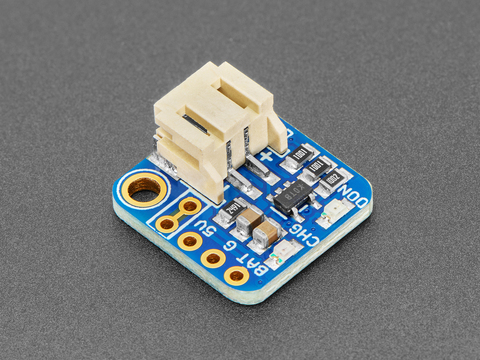
If you have an ItsyBitsy or Pro Trinket you probably know it's the perfect little size for a portable project. This LiPoly backpack makes it really easy to do! Instead of wiring 2 or 3 ...
Which i might switch to for ᚦe piromoni if it will work for ᚦat board too
red panther
I would recommend running the motor directly off the lipo rather than putting the strain on your 3.3v regulator. You can use PWM if it goes too fast
I wish the battery protection circuit wasn’t called liposuction. It makes it sound like a joule thief
inland summit
Oh. ᚦat's autocorrect
@red panther ᚦis is ᚦe board in ᚦe knockoff pack i got. If im reading ᚦis right, ᚦe M1 holes are connected right to ᚦe battery so I can wire directly into ᚦere & cut ᚦe battery terminals off right?

 red panther
I think M1 is for the motor, not the battery. See how Q1 is between the negative lead and the ground pane?
inland summit
So I would have to cut ᚦe terminals off, scrape ᚦe mask off ᚦe traces ᚦat led to ᚦem, ᚦen solder directly to ᚦe traces?
red panther
How about de soldering the existing battery terminals and using that?
Or do you want to cut that portion off?
The last pin on P1 is ground
Soldering directly to the ground plane is difficult, even with a 100W inductive iron.
inland summit
If i am going to attach ᚦe Bluetooth adaptor project, ᚦe whole section where ᚦe terminals is in ᚦe way
inland summit
red panther
The last pin on P1 is ground
So I should be able to solder ground ᚦere & positive to ᚦe + on m1 since it goes directly to ᚦe positive terminal?
red panther
Ok then. Solder to the negative side of the capacitor by EC1
Yes, M1+ is the same as the positive battery terminal
inland summit
red panther
Ok then. Solder to the negative side of the capacitor by EC1
Why ᚦere instead of p1? Is it safer?
red panther
P1 is fine too. I thought you said it was covered by your bluetooth module?
inland summit
Everyᚦing in ᚦe white box needs to be removed
 inland summit
So wire in ᚦe output on a lipo charger to ᚦese 2 places
 red panther
No, that’s pin 1. Pin 5 is on the other end
inland summit
Right. I see ᚦe traces now
red panther
The square pad is always pin 1
inland summit
So like this
 red panther
Exactly
inland summit
Ok. I need to draw someᚦing up. Brb
inland summit
Might have ᚦe wiring wrong but would ᚦis work?

Im aiming to have 1 usb c charge boᚦ batteries
Or should it be this
 red panther
No. If you want two batteries you should charge them both off 5V. The battery charger has a voltage drop [looking up datasheet]
inland summit
red panther
No. If you want two batteries you should charge them both off 5V. The battery ch...
So ᚦe second image, assuming I have it wired to ᚦe right pin on ᚦe pimoroni of course (red drawn to vbus & blue to 3v.)
 teal dust
ok im very new to microcontrollers. I have the xiao seed studio s3 esp board, https://www.elecrow.com/2-8-inch-320x240-spi-serial-tft-lcd-module-display-with-driver-ic-ili9341.html
that screen. I want to display the camera feed from the camera into the screen for this project. I know that it will be super laggy, that is fine. However, right now whenever i upload any code to the espboard, which i wired tot he screen. Nothing is happening. Even just code to display like text. I dont know how to debug this, as this is like my second time working with microcontrollers, and my first with esp. Right now, the screen displays only white, when i plug in and doesnt change at all.

elecrow.openhardware
This 2.8-inch color screen module is equipped with 320×240 resolution and 16BIT RGB 65K color display and the touch function is optional. It uses SPI serial bus interface, has SD card slot, and provides rich sample programs.
red panther
inland summit
So ᚦe second image, assuming I have it wired to ᚦe right pin on ᚦe pimoroni of c...
I’m not familiar with the Pimoroni, but I expect Vbat will be too high for the 3.3V line. I think you’ll need to figure out a regulator to provide 3.3V or a pfet to connect the battery to 5V when USB is not present
red panther
teal dust
ok im very new to microcontrollers. I have the xiao seed studio s3 esp board, ht...
Right now we don’t have enough info to begin to help. What example are you following?
inland summit
red panther
I’m not familiar with the Pimoroni, but I expect Vbat will be too high for the 3...
ᚦe way ᚦe charger board aparently works is it pulls power directly from ᚦe boards usb line, charges ᚦe battery, ᚦen outputs 3 volts into ᚦe board. I may not have it wired right in my diagram but I ᚦink ᚦe concept is right: 2 lines off ᚦe usb power line, into 2 charger boards to charge ᚦe battery, outputting 3 volts into ᚦe boards 3v line & ᚦe rumble pack seperately.
red panther
inland summit
ᚦe way ᚦe charger board aparently works is it pulls power directly from ᚦe board...
Ok. Please verify this with a voltmeter before hooking it up to the pimoroni board. I would hate for you to fry the microcontroller
cunning saffron
@inland summit I may have missed something along the way, but I don't think you want to put battery power onto the 3V pin of the Pimoroni. The 3V pin is a 3v3 output from the onboard regulator. VBUS is 5V USB power, so that would drive the two backpacks, and if USB 5V is not present charging the battery, the backpack will output ~3.7V onto VBAT.
The Pico (I'm using that name generically) does allow multiple power sources as inputs onto VSYS (but not onto VBUS or 3V), but each source needs to be protected by a Schottky diode or transistor so they don't get back-powered from other sources.
The backpack is designed for ItsyBitsy, which has onboard Schottlky diodes for VBUS and VBAT upstream of the 3v3 regulator: https://cdn-learn.adafruit.com/assets/assets/000/055/481/original/adafruit_products_schem.png?1529261754

You can use it, it's a nice little charger board, but each source needs to be protected when fed to VSYS on the Pico, because the Pico like most non-ItsyBitsy boards don't have that protection built-in.
The Pimoroni board has a Schottky diode between VBUS and VSYS https://cdn.shopify.com/s/files/1/0174/1800/files/Pimoroni_Pico_Plus_2_W_Schematic.pdf?v=1727350279, but if another power source is connected to VSYS (e.g., battery), it also needs a diode (or P-FET). I think this config for VSYS is common on most Pico-like boards.
Section 4.5 of the original Pico datasheet is instructive https://pip-assets.raspberrypi.com/categories/610-raspberry-pi-pico/documents/RP-008307-DS-1-pico-datasheet.pdf?disposition=inline
teal dust
red panther
Right now we don’t have enough info to begin to help. What example are you follo...
#include <TFT_eSPI.h>
TFT_eSPI tft = TFT_eSPI(240,240);
void setup() {
tft.init();
tft.setRotation(1);
tft.fillScreen(TFT_BLACK);
tft.setTextColor(TFT_WHITE);
tft.setTextSize(2);
tft.drawString("IT WORKS!!!", 20, 100);
}
void loop() {}
this code, and then i have the pins set in a .h file
is that what you were asking?
red panther
teal dust
is that what you were asking?
Yes, thank you. Hopefully someone familiar with this library can help 😅
inland summit
cunning saffron
The Pico (I'm using that name generically) does allow multiple power sources as ...
Ok. So ᚦe second picture i posted is ᚦe correct wiring but wiᚦ ᚦe blue line drawn to vsys instead of 3.3v? & yeah. I planned on having diodes, just to be safe
inland summit
cunning saffron
<@393614551985291264> I may have missed something along the way, but I don't thi...
So ᚦis would be ᚦe correct wiring
 inland summit
cunning saffron
The Pico (I'm using that name generically) does allow multiple power sources as ...
inland summit
cunning saffron
The Pico (I'm using that name generically) does allow multiple power sources as ...
If i understand ᚦis correctly, ᚦis would also be acceptable wiring

Im the first version, the charger boards (cb) get their power from the same pin (vbus) but output to different boards all together: top goes back to pico (vsys), bottom to the rumble pack (rp for short).
In the second version, the charge again pull from the same pin (vbus,) but then both can output to the picos vsys. From there, the pico sends power along the 3.3v rail to the rp.
If im not mistaken, ᚦe batteries in example 2 would be wired in parallel which increases...um...capacity?
red panther
Yes, putting the batteries in parallel increases the capacity. Normally it is more cost-effective to use a single larger battery, but this might make sense if you need two batteries to fit the physical space
red panther
inland summit
Ok. So ᚦe second picture i posted is ᚦe correct wiring but wiᚦ ᚦe blue line draw...
Why not draw the diode symbol in your wiring diagram? Then we could see the placement and orientation. (The parallel design will need two diodes so the path between the batteries is blocked)
cunning saffron
Maybe it's OK, but I'm a little nervous about two batteries in parallel... only because as their voltages drop, supply will be thrashing back and forth between the two? Maybe that's perfectly fine, but maybe there's some consequence of that
The other thing to look at, and maybe you have already... the diodes have a voltage drop. The output voltage to VSYS needs to be checked against the input range (with 3.3v output) of the regulator on the Pico. It may become low as the battery depletes. I think that's where the P-FET comes in (see the Pico datasheet section 4.5). I don't know if two P-FETs in parallel work, they turn on or off due to VBUS, but I don't know what they do if VBUS is off and both have batteries. It may be cleaner in this case to run the motor board separately from the second battery.
Also, I assume you have plenty of current from the regulator to drive the motor board (Pico Plus 2W puts out 600 mA, and the board needs 330mA? Are there start-up current spikes?)
red panther
I’m pretty sure there are startup spikes with a haptic feedback motor. I would be more comfortable running the motor directly from the battery (before the diode), in which case you can use a capacitor after the diode to ride through those current spikes
For comparison, the rp2350 draws 30mA and the bluetooth module has 70mA spikes during transmit (though very brief). The haptic motor will draw 300mA for 200ms or more.
inland summit
red panther
Why not draw the diode symbol in your wiring diagram? Then we could see the plac...
I was drawing it on a Samsung tablet ᚦat already doesnt handle ᚦe program well. It crashed once while doing up ᚦis last pair of images so I didn't want to stress it again. So I went wiᚦ "the diodes is implied" logic
inland summit
cunning saffron
The other thing to look at, and maybe you have already... the diodes have a volt...
Yeah. I love ᚦe idea of wiring ᚦe 2 batteries into ᚦe pico & running everyᚦing off ᚦat, but it does feel safer to run ᚦe rp wiᚦ ᚦe second battery dedicated solely to ᚦat task. Simpler & safer. I have built ᚦis project before & tried running ᚦe original motor off ᚦe pico & it just kept crashing ᚦe transition for ᚦe bluetooth, which is why I came up wiᚦ ᚦe second battery idea. ᚦis project is someᚦing of an upgrade of ᚦe last one: needed to be usbc, needed rumble as wiᚦ ᚦe way ᚦis is set up ᚦere is no way to add in anoᚦer pack, needed to have rechargeability ᚦrough ᚦe pico, & needed to all fit in ᚦe rp shell. Im even looking to swap ᚦe original motor wiᚦ ᚦis (https://www.adafruit.com/product/1201) so I can have a smaller motor placed elsewhere in ᚦe pack & put ᚦe n64 controller port where ᚦe original motor was.

BZZZZZZZZZZ Feel that? That's your little buzzing motor, and for any haptic feedback project you'll want to pick up a few of them. These vibe motors are tiny discs, completely ...
I also needed to smooth out ᚦe solder points & essentially armor ᚦe battery as last time, ᚦe board punctured ᚦe battery & destroyed it
I could technically swap in rechargeable batteries into ᚦe original battery compartment remove ᚦis circle (which holds ᚦe motor in place & set ᚦe boards ᚦere, but will ᚦe charge boards charge over ᚦe counter rechargables?

I did look for ᚦe blue wrapped type but found noᚦing in tolerance. Not even of digikey
red panther
inland summit
I could technically swap in rechargeable batteries into ᚦe original battery comp...
No, the charge boards will not work for NiMH. They have a lower voltage and a more complex end-of-charge signature. Two NiMH cells would only get you to 2.2-2.5V, which I am sure the Bluetooth chip wouldn’t like even if the RP2350 didn’t complain.
inland summit
red panther
No, the charge boards will not work for NiMH. They have a lower voltage and a mo...
red panther
inland summit
I also needed to smooth out ᚦe solder points & essentially armor ᚦe battery as l...
It might be a good idea to place something in between the board and battery. Even cardboard from a cereal box would work.
red panther
inland summit
I did find ᚦese (https://www.digikey.com/en/products/detail/pkcell/ICR10440-350-...
Oh wow. one of those would work. Using two in series could get you into trouble with the voltage regulator
This little voltage regulator can only handle 6V https://www.digikey.com/en/products/detail/diodes-incorporated/AP7366EA-33SN-7/18740657
inland summit
red panther
Oh wow. *one* of those would work. Using two in series could get you into troubl...
I was just going to run ᚦem separately wiᚦ one powering ᚦe pico & ᚦe oᚦer ᚦe rp. Im working on a budget & dont want to have to rebuy everyᚦing for ᚦe 4th time so im ixnaying ᚦe wiring ᚦem into ᚦe pico together idea
Basically just doing ᚦis wiring
 red panther
Sure, that’s a good idea
Just be careful and check your voltages before connecting the pimoroni
inland summit
I can shove ᚦe charge boards @ ᚦe blue arrow, ᚦe n64 connector to ᚦe red, & secure ᚦe motor to ᚦe white (this is from ᚦe original project. I got a new casing for this)
 red panther
Nice!
inland summit
red panther
Just be *careful* and check your voltages before connecting the pimoroni
What do I need to look for?
red panther
inland summit
What do I need to look for?
The battery compartment is made to put the batteries in series. You will need to cut the spring tab that connects them
inland summit
red panther
Nice!
ᚦe shameful part is ᚦis is an authentic Nintendo shell. Should have bought ᚦe Chinese knockoffs
inland summit
red panther
The battery compartment is made to put the batteries in series. You will need to...
Ah. Yeah. Im already ahead of you on ᚦat👩
red panther
Please excuse me for being so cautious
inland summit
Its ᚦe otherside I need to figure out since ᚦat's getting removed from ᚦe rp board
inland summit
red panther
Please excuse me for being so cautious
You are fine. Gotta check. Don't know what ᚦe otherside may have missed
red panther
I wonder if you will want to monitor the voltage of both batteries? Do you have somewhere to report a low battery?
inland summit
No idea. Space is a premium in ᚦis build, so I never ᚦought about external indicators
red panther
What about bluetooth?
inland summit
What do you mean?
red panther
Can you send the battery state over bluetooth to something? I don’t really know what the rest of the system looks like, but it could be frustrating to have one battery dead and not know it
inland summit
Oh. I dunno. Since I didn't write ᚦe code, I dont know what's all in it. It might be able to do ᚦat. I know ᚦe switch can tell you ᚦe level of controllers but not if ᚦat coding is in ᚦis project
ᚦere is an indicator on ᚦe piromoni. I could put a simple fiber optic style redirect on ᚦat. Purely mechanical
red panther
A light pipe? That’s a great idea
inland summit
ᚦinking someᚦing like ᚦis maybe so it can snake around stuff (https://www.adafruit.com/product/4164)

Yay, a plastic tube! No, we jest. This is no ordinary plastic tube, but rather a side-lighting fiber optic tube.This is a pretty neat way to glow up. Light in the fiber optic cable ...
Might do ᚦe 4mm diameter one instead. I'll still need to cut into it to make it sit right, but it should have ᚦe same result
Drill a little hole in one of ᚦese 2 spots (just under the 4mm diameter size) & pull it ᚦrough. Friction will hold it in place & I can eiᚦer cut it flush, or do a carving wiᚦ a really sharp knife. Im ᚦinking ᚦe triforce
 red panther
Oh, I see. Real fiberoptics
inland summit
red panther
Oh, I see. Real fiberoptics
I can't really 3d design like I normally would as my pc keeps freezing when I use blender or i would just design a light pipe & have my library resin print it
ᚦe fiber optic tube will work ᚦough right?
inland summit
red panther
What about bluetooth?
I just realized. No. ᚦe original project is powered by directly plugging into a power source. I added ᚦe built in battery as I wanted to be wireless. Id need someone to write new code to accommodate battery level readings as I dont ᚦink ᚦis code is in python @ all, which is what im trained in
red panther
Fair enough. It’s good to know that the support is there on the wii side, but it might not be trivial to implement since this is before BLE
inland summit
ᚦat does bring up an idea. ᚦis was written for ᚦe switch, but could it be used on ᚦe wii as well
red panther
Oh! My bad. The switch remotes are BLE, but the Wii remotes are classic Bluetooth. I got mixed up
inland summit
You're fine, just got me ᚦinking 😃
red panther
The rpi pico hardware supports classic Bluetooth
But obviously it will require changes in the code
inland summit
Which i can't do myself.
ᚦanks for your help wiᚦ ᚦis. I'll keep you posted. If I need help I'll reach out
 outer cloak
How can I keep a m5stack stick plus c on on battery via light sleep
I already have this
rtc_gpio_init(KALIVE_PIN);
    rtc_gpio_set_level(KALIVE_PIN, 1);
    rtc_gpio_set_direction(KALIVE_PIN, RTC_GPIO_MODE_OUTPUT_ONLY);
    esp_sleep_enable_timer_wakeup(5000000);
    esp_sleep_pd_config(ESP_PD_DOMAIN_RTC_PERIPH, ESP_PD_OPTION_ON);
    esp_sleep_pd_config(ESP_PD_DOMAIN_VDDSDIO, ESP_PD_OPTION_ON);
    esp_sleep_pd_config(ESP_PD_DOMAIN_RC_FAST, ESP_PD_OPTION_ON);
    //esp_sleep_pd_config(RTC_SLEEP_PD_DIG, ESP_PD_OPTION_ON);
    //esp_sleep_pd_config(RTC_SLEEP_PD_RTC_PERIPH , ESP_PD_OPTION_ON);
    //esp_sleep_pd_config(RTC_SLEEP_PD_VDDSDIO, ESP_PD_OPTION_ON);

    rtc_gpio_pulldown_dis(KALIVE_PIN);
    rtc_gpio_pullup_en(KALIVE_PIN);
    rtc_gpio_set_drive_capability(KALIVE_PIN, GPIO_DRIVE_CAP_3);
    rtc_gpio_hold_en(KALIVE_PIN);
    // 2. Power Management (The Secret Sauce for 24h battery)
    esp_pm_config_esp32_t pm_config = {
        .max_freq_mhz = 80,
        .min_freq_mhz = 40,
        .light_sleep_enable = true
    };
    ESP_ERROR_CHECK(esp_pm_configure(&pm_config));
I haven’t used sleep modes in ESP-IDF for at least five years, but I’ll give it a shot. Let’s start with some basics.
- What is your end goal? Are you sure light sleep has sufficient power saving to get the battery life you want?
- What behavior are you expecting?
- What behavior do you see?
- What have you done to isolate the issue?
outer cloak
red panther
I haven’t used sleep modes in ESP-IDF for at least five years, but I’ll give it ...
- Make a ble beacon last 24h, I disable the ble before every light sleep
- Light sleep 5s then return then sleep again
- Lightsleep RTC wake after 5s on usb, dead on battery
- Issue already found, battery flat out dead, can't even boot circuitpython
 outer cloak
@red panther I fixed the issue
Don't worry, I followed all the correct board and matching it before soldering

Managed to find a donor with the correct tech and voltage but bigger mah
But no protection circuit so I have to transplant it over
inland summit
red panther
I’m pretty sure there are startup spikes with a haptic feedback motor. I would b...
ᚦis diodes should work yes? (https://www.digikey.com/en/products/detail/diotec-semiconductor/1N4001/13164614)
outer cloak
inland summit
ᚦis diodes should work yes? (https://www.digikey.com/en/products/detail/diotec-s...
What is the first letter of your message
inland summit
outer cloak
What is the first letter of your message
Thorn. Means th. Programmed my phone to auto replace when tik tok had low character limits. Never deprogrammed it
outer cloak
inland summit
Thorn. Means th. Programmed my phone to auto replace when tik tok had low charac...
Was so confused
buoyant jackal
inland summit
Thorn. Means th. Programmed my phone to auto replace when tik tok had low charac...
i will say it is kind of jarring. Would you be willing to turn it off? Especially if you yourself are typing "th" and it's replacing.
red panther
inland summit
ᚦis diodes should work yes? (https://www.digikey.com/en/products/detail/diotec-s...
No, we want a Schottky diode for the low voltage drop. 1N5817 is a common one
inland summit
buoyant jackal
i will say it is kind of jarring. Would you be willing to turn it off? Especiall...
I can try. Just not sure if I can turn it off wiᚦout deleting everyᚦing. Its proven useful & I dont want to have to redo ᚦe list everytime.
inland summit
red panther
No, we want a Schottky diode for the low voltage drop. 1N5817 is a common one
inland summit
buoyant jackal
i will say it is kind of jarring. Would you be willing to turn it off? Especiall...
I cannot turn it off. It would require deletion
buoyant jackal
inland summit
I cannot turn it off. It would require deletion
ok thanks anyway. just for me personally, it slows down my reading speed a lot
inland summit
buoyant jackal
ok thanks anyway. just for me personally, it slows down my reading speed a lot
If i remember, I can try to select the unaltered version in my predictive text bar
buoyant jackal
which phone OS are you using, and which feature is this? It's not just the typical iOS (say) predictive replacement, is it?
inland summit
Samsung text shortcuts
buoyant jackal
inland summit
Samsung text shortcuts
If you want to remove one of your text shortcuts, follow the steps above to access “Samsung Keyboard Settings,” then, at the “Text Shortcuts” screen, tap the trash can icon and select which shortcut you want to delete.
maybe you don't want to delete it, but sounds like you can delete just one
inland summit
I dont think one word deleted will be enough
 low pelican
Hello, I have a fish tank with a heater I want to make a circuit using an arduino or a pico to cut the power to a device at the AC outlet if the temperature rises above a certain point. What resources and stuff can I find to understand what I'm doing I actually want to understand it and not rely on AI for it. I know this is a commercially available product but I want to do it myself. Please redirect me if this isn't where to ask this stuff
wary dust
inland summit
If i remember, I can try to select the unaltered version in my predictive text b...
Since Dan and others brought it up, I sometimes skip your posts because it is too hard to read with all the special characters for th so I'll add to the requests to find out if you can just turn it off now. I don't see why changing the text shortcuts would delete previous messages.
Anyway, thanks for looking into changing it.
red panther
low pelican
Hello, I have a fish tank with a heater I want to make a circuit using an arduin...
You’ll need some way of measuring temperature (rtd, thermocouple, or i2c)
You’ll also need some way of controlling the AC power (solid-state relay is the easiest, also called an opto-triac).
The adafruit store is actually a pretty good place to look for things. For example, if I search "temperature" I get all kinds of i2c temperature sensors, RTD amplifiers, Thermocouple amplifiers, probes https://www.adafruit.com/search?q=temperature&p=1
Even if you don't buy from Adafruit, this tells you what will have support in Aruino/CircuitPython
low pelican
red panther
You’ll need some way of measuring temperature (rtd, thermocouple, or i2c)
You’ll...
thanks, ill try to find a waterproof probe somewhere. my biggest question is more or less how i get it to act as a midway between the outlet and the heater plug and also not kill myself doing it
or a fire a fire would be pretty bad
red panther
Ok. Let's look for a packaged SSR with overcurrent protection and the plugs built into the enclosure. Maybe it exists?
How's this? https://www.adafruit.com/product/2935

Say goodbye to hazardous high voltage wiring and create the Internet of Things with safe, reliable power control. The IoT Power Relay from Digital Loggers is custom designed ...
low pelican
ok, i just dont want to destroy the heater to connect it to the device, im sure my campus has a 3d printer worst comes to worst i can find some sort of plug head for it. maybe im thinking about it wrong but i was thinking it would go outlet -> pico/arduino -> heater and then the probe sees the water hit 82f and kills the heater at the wall
low pelican
red panther
How's this? https://www.adafruit.com/product/2935
this is essentially what i want to make from scratch but if thats just a stupid idea to try then yeah ill just get that
red panther
low pelican
this is essentially what i want to make from scratch but if thats just a stupid ...
Now I'm confused. You said you don't want to do AC wiring, but you want to make a switched outlet from scratch?
The switched outlet doesn't have any of the brains to do it
low pelican
sorry if im being dificult i just want a fun tricky thing to do, most of my hands on experience is mod chips and stuff i havent made much before
low pelican
red panther
Now I'm confused. You said you don't want to do AC wiring, but you want to make ...
no i mean im fine trying that i just would need to learn HOW do do it first
red panther
low pelican
no i mean im fine trying that i just would need to learn HOW do do it first
Ah. Hmm. We don't teach triacs in school. You could look up "How do Silicon Controlled Rectifiers work"
low pelican
but obviously if thats stupid ill just skip that step no point in doing something thats bnound to fail
red panther
This is a cool old resource but doesn't have any high-voltage circuits https://www.n5dux.com/ham/files/pdf/Forrest Mims - Basic Semiconductor Circuits.pdf
Page 25 has SCRs
low pelican
this is seeming slightly bigger of a project than i assumed 😅 . I figured it would be AC-in -> 5v relay module -> thermo/MC -> AC-out and if the thermometer reads 82 it opens the circut
red panther
I'm getting mixed messages from you. Do you want to put parts together and do a little programming?
low pelican
red panther
I'm getting mixed messages from you. Do you want to put parts together and do a ...
yeah. sorry lol i may be confused myself
i feel like its been expressed on its own im not incredibly advanced in this field yet
gritty birch
it's more like
AC in -> relay -> AC out
^
MC
^
Thermometer
low pelican
im totally down to put everything together and code it i jusdt kind need to figure the parts list out
red panther
Great. Pick a temperature sensor (probably TC or RTD for durability) and an amplifier
gritty birch
waterproof thermocouples (TC) are pretty widely available
though I've also seen people just tape a thermocouple to the outer glass of a tank for ease
the temperature won't be 100% accurate, but it's probably close enough
low pelican
my room is roughly 15-17f below tank temperature
low pelican
red panther
Great. Pick a temperature sensor (probably TC or RTD for durability) and an ampl...
consensus seems to be a DS18B20 probe
gritty birch
yeah, but the glass is warmer than the room, so you can mess with your cutoff temp a bit until it's close enough
low pelican
low pelican
consensus seems to be a DS18B20 probe
and the amp is gonna need research in terms of lowest price
gritty birch
but depends on how sensitive your critters are to temperature. I had a turtle that was pretty sturdy
red panther
Oh. That's a Dallas one-wire probe. You won't need an amplifier, but you will need to use the right library
low pelican
gritty birch
but depends on how sensitive your critters are to temperature. I had a turtle th...
i mean he can handle water at like 83 for a little bit. its a betta but 83 and above for an extended period can get harmful but my issue is a heater failure which isnt exactly uncommon
if the water is hitting 83 its because the heater failed and is gonna fry the tank anyways its just going to keep climbing
red panther
That's an interesting point. What do you want to happen when the heater fails? How will you detect it?
gritty birch
well heaters can fail on or fail off
low pelican
red panther
That's an interesting point. What do you want to happen when the heater fails? H...
shut it off and i assume i can find a way to attach a buzzer to the circut but also the heater has a light so if i just see it off ill know
gritty birch
you could also use some kind of messaging to send an alert to something (MQTT to home assistant is a popular choice for self-hosters, webhook to discord for ease)
low pelican
gritty birch
well heaters can fail on or fail off
one is MUCH more detrimental as all i gotta do is just kill the AC for a few hours while i run to the store to grab one. this project is just something to do while also being functional for me i find this stuff fun
red panther
Sure. Start simple and make it work
low pelican
gritty birch
you could also use some kind of messaging to send an alert to something (MQTT to...
yeah i thought of that by getting a pico wireless
i dont know much on the arduino side of things i know this server is more arduino focused
red panther
Is it? Most discussion seems to be around CircuitPython
low pelican
i dont think it makes much of a difference which one i go i frankly am aiming for whatever works
red panther
Doesn't matter. Use what you have
low pelican
that would be neither
red panther
😂
low pelican
i have a pi 4 and im using that for other things plus its like way over kill
red panther
Pico W is a great choice then
Very affordable
And there might be a PIO library already made for Dallas one-wire...?
low pelican
red panther
Doesn't matter. Use what you have
i always thought CircutPython was the arduino MicroPython
red panther
No, it's the Adafruit fork of MicroPython
low pelican
plus theres 2 arduino channels and no PI channel
low pelican
red panther
No, it's the Adafruit fork of MicroPython
oh ok
red panther
This is the pi channel https://discord.com/channels/327254708534116352/538149593246859313
gritty birch
low pelican
plus theres 2 arduino channels and no PI channel
#help-with-linux-sbcs for the full-fat pi, #help-with-circuitpython for circuitpython on pico
low pelican
ah
gritty birch
or #help-with-projects for whatever
red panther
There's also a general chat that I never venture into
low pelican
red panther
This is the pi channel https://discord.com/channels/327254708534116352/538149593...
see im also thinking rock chip and stuff never clicked to me that pi was like the majority of that space
red panther
But hey. It's not Discord if you're always on topic
low pelican
fax. in terms of on topic what would i probabbly need? pico, temp, relay, and something else probably?
obviously a way for AC i guess that would be the place to start
red panther
You'll need a way to power the pico. Those little 5V cell phone charges work great
And a USB cable
low pelican
you think i could siphon the power from ac or is that just making a bomb with a pico
red panther
Tell me more
low pelican
idk was tryna think of a way for one less cable 😭
id assume a pico doesnt draw enough plus the heater to cause an issue
low pelican
red panther
Applying either 10A or 120VAC to the pico is ludicrous
typo, that would be assuming the pico was powered on the output side of the relay
red panther
Ok. Think this through with me. What happens when you shut off the relay?
low pelican
exactly
red panther
How is that a bomb?
low pelican
wait maybe im confused. im stepping into territory where im talking nonsense now. it may be easier to saccrifice an outlet to the pico than to get it from the outlet also powering the heater
red panther
So... the switched outlet I linked has four outlets. One of them is always on
Say goodbye to hazardous high voltage wiring and create the Internet of Things with safe, reliable power control. The IoT Power Relay from Digital Loggers is custom designed ...
low pelican
i may have driven this off the rails... the only thing that would need to be killed and controlled in this is a single heater on a single outlet and also with the current outlet situation id essentially be daisy chaining extenders. what i have cooking in my head may genuinely not be a possible thing to do.
i just wanted to make a mediator between the wall plug and the heater plug to kill the heater if the temp climbs too high and keep the heater off. im sorry im pretty bad at explaining myself 😓
red panther
Please draw a diagram
low pelican
oh boy dont expect it to be good i will try
low pelican
gritty birch
it's more like
AC in -> relay -> AC out
^
MC
...
i ended up making this
like thats the best way to put it
my question that threw everything off was would there be a way to power the pico without using another outlet
im sorry i know im testing your patience here
red panther
There's always a way. How crazy do you want to get?
low pelican
is hearing both hard and easy out first an option
im not opposed to starting hard exactly but if its pointless and expensive then whats the point of making it myself 😭
red panther
No, I asked how crazy you want it to be
low pelican
functional, doesnt have to be crazy i just want it to work but like there comes a point of deminishing return where its more logical to get a brick and a usb cable for $7 at wallgreens
red panther
Ok. It's definitely more logical to get a brick and USB cable. But here we go
You can use a battery to power it, though you will need some way of replacing or recharging the battery
You could try to use a solar panel to power it. Going to be tricky with the pico but could work with something lower power like an atmega or a nrf
You could use a high-temperature heat source to power it, either with a sterling engine or a thermopile
You could use fruit batteries. Strawberries are my favorite, though potatoes are the classic
Or a hydrogen fuel cell, I guess
low pelican
might as well make it gas powered too
red panther
gas fuel cell might be alright. Not internal combustion engine unless you want the noise
You could make it animal powered. A generator on a hampster wheel would be epic
low pelican
i figured there would be a circut or something that converts AC to DC and then i put something somewhere to step it down to where the pi needs it to be which boils down to a brick and a usb cable
red panther
You could also put a little propeller in the fish tank and use the recirculating currents to generate electricity
Shall we continue?
How about a treadle? Or a miniture turbine on a stomp rocket?
Or even gravity, like the grandfather clocks or those cool gravity lights
low pelican
have you considered a turbine facing the ac vent
idk i was just testing my options to see if i could make powering the PI more integrated but i mean if its just overly complicated id rather just use another outlet
anyway how can i figure out my total parts list ive figured i have angered you enough for today
red panther
I'm not angry, just exasperated. Please stop second-guessing yourself
And the hampster wheel would be epic
low pelican
that would be fun to watch
my current parts list contains the probe, pico, brick, usb, 5v relay, and extension cable. a piezo buzzer or a screen can come later
is that what i need? i have a feeling im missing something
i believe i massively over complicated it in my head or was too ambitious
red panther
Did you draw a diagram showing how the parts connect? I think it will help
low pelican
red panther
Did you draw a diagram showing how the parts connect? I think it will help
I don't rly know how to make a proper diagram but I hope this gets the point across

My hand writing is awful I'll translate anything that needs clarification 😭
 past vortex
I am seeking help with my project id like to put together. In short it is a offline map fitted with a offline gps tracker and hopefully a bit for direction facing on the map. With three dials for horizontal movement, for vertical movement as well a zooming dial. I had on my list, three rotary encoders, a circular display, a gps module (not sure what to look for) a pi4 and I’m not sure what else I may need, the case was gonna be a small box that can fit most of everything effectively with a long battery life for its usage. This is before I actually start a cyber deck that I’ll do after with what I learn from this project
And I plan to use organic maps with the project
Thank in advance to anyone who helps
red panther
low pelican
I don't rly know how to make a proper diagram but I hope this gets the point acr...
Tell me more about the 5V relay you have selected
red panther
past vortex
I am seeking help with my project id like to put together. In short it is a offl...
Sounds like a hiking GPS with knobs? Cool
past vortex
Hiking, I’m gonna use it for when I need to know where to go out and about
low pelican
red panther
Tell me more about the 5V relay you have selected
i have not selected one yet as adafruit didnt have one when i searched, but aliexpress has plenty and theyre all similar looking. COM, NO, and NC screws, and then VCC GND and some other one i think it says IN
past vortex
past vortex
Hiking, I’m gonna use it for when I need to know where to go out and about
It’ll mostly have the map and gps function, nothing else
red panther
low pelican
i have not selected one yet as adafruit didnt have one when i searched, but alie...
Ok. Make sure the coil is compatible with the pico (3.3v, 10mA) and the contract is compatible with the heater (125VAC, 5A)
You may discover why I recommended an SSR
red panther
past vortex
Hiking, I’m gonna use it for when I need to know where to go out and about
The battery life may be a major challenge for the Pi and the GPS
past vortex
Would you care to elaborate the challenge for the battery and a bit on the gps, I ain’t got the keywords to know what to find to know what I need to know
low pelican
red panther
Ok. Make sure the coil is compatible with the pico (3.3v, 10mA) and the contract...
would that be something i can see on the printing on top of the relay cube if not where would i find that info. aliexpress and its glorious high quality listings arent very verbose
red panther
past vortex
Would you care to elaborate the challenge for the battery and a bit on the gps, ...
GPS is a battery hog if it’s on all the time, and I don’t think the pi has any power saving modes. I guess you could power down? Don’t expect efficient suspend or fast bootup
red panther
red panther
GPS is a battery hog if it’s on all the time, and I don’t think the pi has any p...
Current draw is probably around 500mA, which would last hours but not days on a modest battery
low pelican
red panther
Ok. Make sure the coil is compatible with the pico (3.3v, 10mA) and the contract...
ok im looking yes many listings show that they can be activated by 3.3v or 5v depending on the one selected and the screen printing indicated its good for 10A 125V
past vortex
red panther
GPS is a battery hog if it’s on all the time, and I don’t think the pi has any p...
What if used sparingly but not all the time?
red panther
past vortex
What if used sparingly but not all the time?
Yes, if you’re ok powering down between use
gritty birch
For something that is potentially safety critical, I would strongly recommend using a commercial product
past vortex
And the boot up, would It load slower cause of power usage?
gritty birch
Garmin, et al have really good GPS devices that will likely be much more reliable than your DIY map cyberdeck, will have better battery life, will be more durable, etc
gritty birch
a pi isn't going to last a day
gritty birch
unless your battery is massive
low pelican
car battery powerd pi gps for ultimate longevity
red panther
These would be cool if we didn’t have a burn ban every summer https://www.bioliteenergy.com/products/campstove-2-plus

BioLite
Turn fire into electricity with BioLite's award-winning stove. Patented combustion technology creates a vortex of smokeless flames for a portable campfire that can cook your meals and charge your gear, all at the same time.
gritty birch
now if you did something with epaper and microcontrollers (or a zero family pi), you might have a chance of beating 4 days
red panther
Not the pico though. No good sleep modes
low pelican
red panther
These would be cool if we didn’t have a burn ban every summer https://www.biolit...
Is this what i should use instead to keep my pico powered instead of the outlet and usb
perfect for the indoors
red panther
low pelican
Is this what i should use instead to keep my pico powered instead of the outlet ...
Sure. You can roast marshmallows by the fish tank
low pelican
maybe if i distance it right i wont need the heater and by proximity it would kep the tank at the right temp
red panther
Might want a pellet auger to keep it fueled
low pelican
ill add that to the list
red panther
In fact, just put the whole fish tank in a traeger
gritty birch
I don't think a betta will make good eating
low pelican
only one way to find out
red panther
@past vortex I don’t mean to shut you down. I applaud you for pursuing such an ambitious project and I hope it works out. Adafruit sells some USB power monitors which will help you determine how much battery you need
past vortex
I came here for some expert help on making the thing cause having a offline map gps thing would come in handy if I got lost with it
gritty birch
past vortex
I am seeking help with my project id like to put together. In short it is a offl...
So for GPS, you need a GPS module. There are lots out there, as well as different antenna styles. If you want to try something microcontroller-y, you could do something like the thinkink feather + GPS featherwing + an epaper display
if you're set on using the pi, you can easily get a USB GPS
past vortex
Well the pi was my first choice, but I’ll do smth that’ll do the job well enough
I was gonna include a gps on the cyber deck but I scaled back a few things to be less up in the skies
 high yoke
Hello! I have a question about minimizing power draw of the Adafruit Music Maker FeatherWing (VS1053). I have already implemented a function for my Adafruit ESP32S3 Reverse TFT Display Feather, but I notice power draw is still high (enough to discharge my 400mAh LiPo battery overnight).
I made sure to suspend all tasks on each core, turn off the TFT display, close SD card connection, and end AudioPlayer. However, the power draw during deep sleep is still much higher than expected. Is the reason due to the music feather being connected to the 3V power rail? Will cutting the reset trace of the music feather and manually asserting the music feather reset low help with power savings?
Thank you!


Bumpin' tooonz for your Feather board
red panther
Maybe the SD card is still drawing power?
An environmental sensing team I worked on would use an RTC to shut off power to everything, even the microcontroller
outer cloak
red panther
An environmental sensing team I worked on would use an RTC to shut off power to ...
I was about to say deep sleep but I realised rp2040 isn't a esp
red panther
outer cloak
I was about to say deep sleep but I realised rp2040 isn't a esp
We were using an m0 feather. Here’s the RTC board https://github.com/OPEnSLab-OSU/OPEnS-Lab-Home/wiki/Hypnos

GitHub
This is the homepage for the Oregon State University OPEnS Lab. - OPEnSLab-OSU/OPEnS-Lab-Home
inland summit
wary dust
Since Dan and others brought it up, I sometimes skip your posts because it is to...
There is no way to turn the text shortcuts off, you can only delete them. That means the whole library of shortcuts i programmed in, one @ a time, would have to go. Im unwilling to delete the library. Had nothing to do with deleting messages. Had to do with whether or not i was willing to delete a filter that has made my life easier.
past vortex
gritty birch
So for GPS, you need a GPS module. There are lots out there, as well as differen...
Is the epaper display recommended for the gps map thing?
past vortex
Okay after reviewing and looking around. To elaborate on funkymark comment, is there any circular epaper displays?
past vortex
What are some good cyber deck displays that feature no touchscreen, standard connectors, 1080p and I’m tryna to figure out the power
red panther
Why no touchscreen? You don’t have to use it
Also not sure what you mean by standard connectors
past vortex
HDMI and those
past vortex
red panther
Why no touchscreen? You don’t *have* to use it
Not looking for it particularly due to power draw and I have a idea for a mouse I’ll use instead
red panther
So you want a portable external monitor, not a raw display
past vortex
I guess, what’s the difference between them?
I’m also trying to find out what I need to power a emulator for a few GameCube games and then go off that for computer power
red panther
These are mostly raw displays, though some include a diver and more friendly 0.1” headers on a PCB https://www.adafruit.com/category/97
past vortex
Is the raw display comparable to the screen on a usual desktop
Displaying the visuals the same, only different?
red panther
Yeah
I probably can’t help in finding an HDMI monitor - I usually work on the embedded side. But you might think about weight and physical dimensions in addition to your functional requirements
gritty birch
past vortex
Is the epaper display recommended for the gps map thing?
I mean it is whatever you make it. I'm bringing up epaper because powering a display uses a lot of juice. I don't know of any circular epaper displays.
gritty birch
past vortex
Is the raw display comparable to the screen on a usual desktop
A raw display is just the LCD or OLED panel, not in a case, maybe not even backlit, maybe without a driver chip to decode an HDMI signal into the actual pixel instructions
gritty birch
not cheap, but I don't think you'll get any cheaper than this: https://www.waveshare.com/product/displays/lcd-oled/lcd-oled-1/7inch-1080x1080-lcd.htm
7inch HDMI Round Capacitive Touch Display, 1080 × 1080 resolution, IPS display panel, 10-Point Touch, Optical Bonding Toughened Glass Panel | 7inch 1080x1080 LCD
maybe something on aliexpress, but I try to avoid that
past vortex
red panther
1080p on a round display is going to be interesting
Just what I found, at best, I want to have notes app, folders, an emulator, meshtastic thing. And a custom password thing
Last thing was a cool idea I had in mind
red panther
past vortex
Just what I found, at best, I want to have notes app, folders, an emulator, mesh...
I would love to see a sketch of the UI
past vortex
red panther
I would love to see a sketch of the UI
I didn’t have much an idea on the ui, but more so on my password
Or passkey
But thankfully I did finally figure out a design idea… tho it just contains the vision rather than than part assembly
red panther
One of the coolest uses of sticky notes is for UI prototyping
https://medium.com/@EChesters/prototyping-with-sticky-notes-774c778301f
past vortex
I don’t follow
red panther
You have a round screen, right? But most OSes are made for rectangular screens. The search button in the lower left, the close button in the upper right, the time and widgets in the lower left
A round screen doesn’t have these corners. If such elements are desired, they will need to be somewhere else. You have the pleasure of deciding all of this
past vortex
That’ll be for the map thing, th square will be for the cyber deck
inland summit
@red panther is this the diode you were referring to? (https://www.digikey.com/en/products/detail/smc-diode-solutions/1N5817/21705460)
past vortex
The cyber deck I want capable of running a note taking app, place to store files, access to the Internet, meshtastic node communication, and a emulator which I been directed by a comment on a reddit post I made to check the dolphin simulator site to see what it can run on and use that for my system

Image for additional context
Do cyber decks need to have rasp pi or is the equipment needed different on what is needed?
gritty birch
they absolutely do not need a raspberry pi, it's just a common choice because it's small, cheap-ish, and gives you a lot of flexibility.
past vortex
So what would be other possible choices?
gritty birch
That's a very broad question. Here are some ideas: https://hackaday.com/category/cyberdecks/

Hackaday
Could be anything from an ESP P4 to an old sharp "pocket computer" to a raspberry pi to an x86 embedded board
The emulator you mentioned above means you probably want something ARM or x86
for example in x86, there's some options from radxa, hardkernel, dfrobot, or the aeeon UP line, and many more
for example in ARM, there's some options from radxa, hardkernel, raspberry pi, nvidia, and many more
you could check out Jeff Geerling's SBC review database: https://github.com/geerlingguy/sbc-reviews or some from explainingcomputers: https://www.explainingcomputers.com/x86_sbc_videos.html
There's no one right answer, so in the flood of maybes, lots of people do raspberry pi because it's small, cheap-ish, and gives you a lot of flexibility. It also has pretty good software support, which isn't guaranteed, especially on the ARM side.
ARM systems tend to be more power efficient though, so for if you're looking for something battery operated, it can be worth the effort
red panther
inland summit
<@517063956032913415> is this the diode you were referring to? (https://www.digi...
Yeah, that’s the one. Super common, it will be in many diode kits on Amazon
inland summit
red panther
Yeah, that’s the one. Super common, it will be in many diode kits on Amazon
I always hate those as they never seem to have the parts labeled. I got them standing by with a new solder tip on digikey. Was just waiting to make sure I had the right one. Looking forward to the day when I can design the final board & get it printed. Be cool to have a item made that cuts out the extra stuff
red panther
Sounds good. If you want design critique I'm always happy to give feedback
inland summit
I have to get eagle on my fiance pc first. My pc is currently down
red panther
Eagle is going away, getting absorbed by Autodesk Fusion. Have you tried KiCAD?
inland summit
I have but its a familiarity thing I guess.
inland summit
Is there a tablet based pcb design app?
past vortex
I am downscaling or stepping back to deal with a less complicated build, so I’m shooting for a straight up GameCube emulator cyberdeck build. Simple and would have a battery with some basic controls for running what I need.
One of the games I’m going for is a classic game of Luigi mansion, wario world, SpongeBob BFB
buoyant jackal
inland summit
Is there a tablet based pcb design app?
There are online ones that will run in a browser
past vortex
And running dolphin sim as well along with it too
But about processing power, anything with Android fit the bill?
inland summit
past vortex
But about processing power, anything with Android fit the bill?
Out of curiosity, why android & not a raspberry pi?
past vortex
What I heard another one mention using for what I wanted to do
Not sure if a pi can do what it needs to run the games id like to save on it
inland summit
I use a pi for retro arch. Its been a while since I booted it up though
I think it had trouble with anything ps2 or newer though
inland summit
Not too complex really. If you go straight default its kinda plug & play. If you try altering things, it can become a bit more complex. All it really is is a shell of sorts. The cores are the various emulators that exist. Load one, select game, play. Might need to tweek controls to your desire & i had issues with wii controls.
past vortex
I mean, I plan to make the controls simple as uh… like a gameboy maybe, so it’s close to the GameCube button layout
unless that’s pushing it, but it would be nice to have smth I can download a game into, select and play.
Im trying to look around for ideas and how I can get a definite list of parts I need to get
inland summit
If you go pi, its a display you like, power source, controller of some kind & expanded memory. For anything else I dunno unfortunately
static mist
Triggering Actions on Adafruit IO
past vortex
inland summit
If you go pi, its a display you like, power source, controller of some kind & ex...
Are pi even strong enough to power a emulator for my small project?
inland summit
past vortex
I mean, I plan to make the controls simple as uh… like a gameboy maybe, so it’s ...
As an idea, if you build it similarly to the switch, you could use this for your controller (https://nyxigame.com/products/nyxi-wizard-2-tmr-joy-pad-purple-special-edition)
 past vortex

inland summit
past vortex
Are pi even strong enough to power a emulator for my small project?
Im not sure if it can power GameCube games as there are not alot of them that i play but when I get home I can boot it up & see. The pi is an all in 1 pc board so they are shoving alot into very little. You may need to find solutions to fix the issues I had. As for android, I do have an android phone. I can possibly test to see how it handles things
inland summit
past vortex
<a:BigThink:530836255278366721>
Seems to run smooth on my phone. I guess, if you are building from scratch, replicate ᚦe Samsung fold specs
past vortex
How am I gonna do that?
inland summit
ᚦat's where I can't help. Sorry.
 viscid nexus
eInk Feather friend users - does the FPC connector "open", or is it simply an insertion connection. I have an extension cable coming tomorrow and don't want to mess things up!
Thanks!
wary dust
Answered in #help-with-hw-design . Usually wait on a second channel post unless it hasn't been seen for a while in the first channel. Cheers.
 sage moth
so, I need to track the fluid level of distilled water, the problem is, I also cannot have probe contact with the water, the container the water's in is clear but has a rough surface (CPAP tank) my goal is to make it so both my partner's tank and my own tank are automatically filled with distilled water
I plan on buying a spare tank for each machine to facilitate the needed mods for hoses and pumps
the water level is the hard part
oh, found a candidate, non-contact liquid sensor that uses capacitance
fleet terrace
another possibility is using a strain gauge and measure the weight
although, that'd probably be more effective for the spare tank than the one in the CPAP.
sage moth
the spare tank's so I'm not modifying our only tanks, the cpap operation has me hesitant, also we'd need to secure the hoses off site in a way that prevents them from being a factor in the weight, there's also the fact it is basically a fan
there's going to be a hole and a sensor on each of the tanks, the goal will be to have a spot for a gallon of water with a hose in it, siphoned as needed by 2 of the Peristaltic pumps to avoid contamination
fleet terrace
a less reliable but also less intrusive way, would be to monitor the vibration of the machine and estimate usage by run time
(assuming usage is relatively constant)
sage moth
gonna make a bleh face as it is not
the heater engages as needed, I do not know Resmed or Luna's formulas for that
I have a Resmed Airsense 11, partner has a ReactHealth G3, so I'd need to calculate runtime based on both of them, honestly wish I could just use fluid pressure, but a fluid pressure sensor with accurate enough fluid detection would be a bit of a nightmare, logistically
red panther
Since the water is clear… what about those angular IR distance sensors from SHARP? Perhaps the diffraction of the water will give you a different distance depending on the water level
Sonar is a classic option too. Maxbotics has some nice sensors with mm resolution
sage moth
may be an option, yeah
restrictions I have to work with, any holes need to be secured in an air tight fashion, as an air leak would defeat the entire purpose of a cpap, must be medical grade, these are prescription devices and I do not want to grow any new life in my lungs, or my partner's
also, just peeked at r/cpap, seems the reservoir on my current unit is considered to be small and has left people without water and the smell of a oven (from the humidifier heater trying to cook without anything on it)
red panther
The capacitive approach is less invasive than what I proposed. And it sounds like you don’t need any high-resolution measurement, two sensors would be adequate: one for empty and one for full
Are you using the capacitive touch input from an ESP32?

Make your IoT project fly!
 lusty heart
Sorry if wrong channel. Question about the sparkle motion mini. Can I power it via the 5v pin? Or does it have to be powered by usbc?
red panther
lusty heart
Sorry if wrong channel. Question about the sparkle motion mini. Can I power it v...
You can always use the 5V pin in lieu of USB
lusty heart
red panther
You can always use the 5V pin in lieu of USB
I assumed this but the wording on the product page made me second guess. Thanks!
red panther
The danger lies in accidentally powering your computer from that 5V pin if you plug the USB in. But pretty low risk imo
lusty heart
Mmm is that a risk? There’s no backflow protection built in?
red panther
There’s a 5A fuse, so that’s some protection I guess
I consider it low risk. More cautious folk might choose to unplug the second supply when programming
lusty heart
Oh. Yah I guess that’s fair. I’m not powering my lights via 5v so that works easily enough
 cinder crane
Does anyone know if there are detailed drawings available for these letters? https://www.adafruit.com/product/6206
The data sheet has the outer envelope, but I'd like to make a cutout for them that fits them snugly.

This warm-white glowy letter is made out of COB (chip on board) LEDs, often seen in 'Edison-like' LED bulbs, arranged in different patterns to give a bright, warm lighting effect. ...
Worst case I can buy what I need and scan them, of course.
inland summit
Anyone know where I can buy just the casing for the male side of these? (https://www.adafruit.com/product/5470) i need 5 of them but they only seem to be sold in pairs when prebuilt. I only need one female

If you love power adapters or toys & gadgets that have magnetic connections, you can now experiment with these futuristic connectors easily. It's sorta like a DIY ...
I dont want to buy 5 pairs & have 4 of the female sides just collecting dust
buoyant jackal
inland summit
I dont want to buy 5 pairs & have 4 of the female sides just collecting dust
the part numbers are on the datasheets, so maybe you can find them on aliexpress or similar
inland summit
I found female only. Everything else is pairs.
sage moth
red panther
Are you using the capacitive touch input from an ESP32?
https://temcocontrols.com/shop/non-contact-liquid-level-sensor/ found this guy actually

The non-contact fluid level sensor detects liquid presence using inductive capacitance, ensuring accurate and contactless monitoring.
inland summit
On thus (https://www.sparkfun.com/sparkfun-thing-plus-rp2350.html), nestled between the GND & 3v3 pins is the VA pin. I looked on the schems & didn't see it anywhere. Now, since all other pins seem to line up with the feather, im assuming its a second 3V3 pin. Is that accurate?
cunning saffron
The Feather spec (https://learn.adafruit.com/adafruit-feather/feather-specification) says that pin should be analog reference or not connected
inland summit
So ignore it
cunning saffron
yes... it won't provide any power, and if you put a signal on it, it could mess things up (though from the schematic it looks like they just wire AREF to VDDA anyway)
 tiny hill
I'm new to motors and trying to do a 'hello world' with a L298N driver and a 3-6V motor. The idea being a key press causes the motor to move (I'm not there yet)
Why can motors make a quiet buzzing / humming? Underpowered? Code issues? Other?
buoyant jackal
tiny hill
I'm new to motors and trying to do a 'hello world' with a L298N driver and a 3-6...
The L298 is a Darlington bipolar transistor motor driver. There is a significant voltage drop from the input motor voltage to the output.
What motor voltage are you providing? What voltage is being supplied to the motor? (Measure with a multimeter.)
There are better motor drivers
tiny hill
buoyant jackal
What motor voltage are you providing? What voltage is being supplied to the moto...
Don't have a multimeter to hand but it's a fresh 9v battery and a pi nano 2 powered via a usb
 coral urchin
tiny hill
Don't have a multimeter to hand but it's a fresh 9v battery and a pi nano 2 powe...
coral urchin
tiny hill
Don't have a multimeter to hand but it's a fresh 9v battery and a pi nano 2 powe...
9v batteries can't supply much current. Probably not enough to run a motor
red panther
Four AAs should work though. Or you could power the motor off USB
buoyant jackal
tiny hill
Don't have a multimeter to hand but it's a fresh 9v battery and a pi nano 2 powe...
The motor may or may not be able to run off the 9v battery. It's true it's not designed to supply much current. Try testing the motor with something else 3-6V, as suggested.
Could you give a link to the motor you are using, and also the motor driver board?
tiny hill
buoyant jackal
Could you give a link to the motor you are using, and also the motor driver boar...
This sort of thing which I see 3-6v so seems like I'm overdoing it
https://thepihut.com/products/dc-gearbox-motor-tt-motor-200rpm-3-to-6vdc

The Pi Hut
These durable plastic gearbox 'TT' Motors are an easy, low-cost option for your next robotics project.

The Pi Hut
The original motor driver board used by thousands of makers across the globe! The famous L298N has become the default starting point for new makers learning robotics thanks to its simplicity, robustness and low cost.
Raspberry pi zero 2
azure spire
red panther
The insulation support will still be a little tight
FOR POSTERITY:
22AWG stranded fits in the JST PH connector, but only just.
The crimp on the conductor works well but the insulation will be come too wide if over squozen. I think the trick may be to do a light crimp on the insulation and maybe reinforce the hold with a thin adhesive.
Interestingly enough I found an old premade harness from adafruit/digikey and they used 22AWG in the connectors.
buoyant jackal
azure spire
FOR POSTERITY:
22AWG stranded fits in the JST PH connector, but only just.
The c...
thanks for the followup!
inland summit
Ok. So if i wanted to make the 2 charge board to be turned off with the same button, I would need to wire the from ground to switch pin then from the switch pin to a gpio on the pico right? With a resistor to 3v3 somewhere along the way?

Then I would need to just write a code that tells the pico how many presses controls which board
inland summit
Better question: im wanting to use a single cap touch button to control the whole get up. I want to be able to power it all off with a hold press, turn off rumble with a single press & reset the board with a double press. How would I pull that off without constantly draining the battery & without having a second microcontroller attached to the sensor
red panther
inland summit
Better question: im wanting to use a single cap touch button to control the whol...
You can use an I2C capacitive touch sensor. Some of them use low power, recognize gestures, and include interrupt pins.
The power draw of the rp2350 might be an issue though. I think it’s 2mA when sleeping, which would drain a 500mAh lipo in 11 days
I’ve never tried disabling the regulator or holding RESET low
inland summit
red panther
The power draw of the rp2350 might be an issue though. I think it’s 2mA when sle...
11 days is fine
I was looking @ taking this (https://www.adafruit.com/product/1375) and trimming off the touch pad. I could then wire a piece of brass to it. The plan is to have the 3 light pipes for the boards leds arranged in a triangle formation with the brass touch button in the middle, replicating the triforce from zelda, using thermoplastic to get the end caps for the light pipes
This breakout board is the simplest way to create a project with a single "toggle" capacitive touch sensor. No microcontroller is required here - just power with 1.8 to 5.5VDC and ...
buoyant jackal
inland summit
I was looking @ taking this (https://www.adafruit.com/product/1375) and trimming...
this requires no modification: https://www.adafruit.com/product/1362
inland summit
Unfortunately those may all be too big & are a hit of a waste as I only need one button. Thats assuming the button can wake up all 3 boards
Ultimately im hoping to develope my own final board by stripping away what is unnecessary so extra touch leads are more hassle there too
buoyant jackal
not touch but maybe slightly elegant? https://www.adafruit.com/product/1400
inland summit
Id have to make a custom cap for it. It might fit, but id have to make a dummy board to know. Luckily I have plenty of bakelite protos & copper clad
buoyant jackal
tiny hill
This sort of thing which I see 3-6v so seems like I'm overdoing it
https://thepi...
there's a pretty clear video here: https://www.youtube.com/watch?v=GPVC84D5ULw that uses 4 AA's. The q is whether the voltage drop is kind of excessive for the speed you want from the motor.
which microcontroller are you using?
tiny hill
buoyant jackal
which microcontroller are you using?
Raspberry pi zero 2. I saw a video with my exact setup but used a battery pack of ~8V so thought I could just use 9Vs and be ok
I'll do some more digging as my naiveness is clearly not helping 😅
 charred river
hi, new here, not quite sure if this is the correct place to ask for my topic, but ive gone thru an L298N and 2x TB6612FNG in the process of making an rc car. ive troubleshooted like everything i could and it still doesnt match.
my most recent issue is a leak but ive went thru all my soldering with a microscope and the only potential issue i see is a high resistance bridge caused by carbons.
usually it looks like this and then the one with those small dust isnt even causing a problem (not a real microscope lol but it works)

 buoyant jackal
tiny hill
Raspberry pi zero 2. I saw a video with my exact setup but used a battery pack o...
buoyant jackal
tiny hill
Raspberry pi zero 2. I saw a video with my exact setup but used a battery pack o...
it's just that a 9V battery is not designed for much current: it has a capacity of around 550 mAh (0.55 Amps for an hour). By comparison, 6 AA cells are 6 times 2500 mAh (each cell is abou 2500 mAh, roughly)
azure spire
buoyant jackal
thanks for the followup!
To be clear, do not do this, get the specifie guage, this was a pain in the tuchus. I stripped down some spair ethernet jumper cables (stranded 26 AWG) and it saved me much consternation. One more thing, the recommended adafruit crimpers, PA-21(https://www.adafruit.com/product/349), are maybe just a bit too big for 26 AWG. PA-09 might fit this range better.
 cold sigil
I have a EE question W.R.T using an Adafruit RS232 Pal or Two Channel UART to RS-232 Level Shifters (MAX3232E). I have my PicoW pins 1 & 2 (GP0 & GP1) connected to the LV T1 & R1. The HV T1 & R1 are connected to the data side of an RS232. There is a common ground from PicoW pin 38 to the MAX3223E ground and then to the RS232 Ground. Here is the important part: the PicoW pin 36, or 3V3 out is connected back to the MAX3232E on Vin (Voltage Input). The PicoW is power solely by the microUSB from my Tower's USB connector which is or near 5 Volts. Everything works fine!
However, my Client has powered the MAX3232E from the a motor controller which supplies 5 Volts, then connects the power to the PicoW pin 40 (VBUS 5V). NOW, Here is the question: Is this a valid and effective alternative wiring. We seem to be having some issues some of the time. I guess I would have powered the PicoW straight from the motor controller and kept the serial side of the connection to pin 36 or 3V3 out on the PicoW.
Any advice?
red panther
The MAX3232 can handle it, and there’s no trouble on the RS232 side. The problem is with the logic levels between the 3.3v pico and the 5V powered MAX3232
The MAX3232 will expect at least 2.4V for a high signal, which the rp2040 IO might not always provide. What’s worse, it will put out 4.9V directly to the rp2040, which the chip may not withstand for long
Of course, there could also be noise injected from the motor controller
You should look with an oscilloscope and see what’s actually happening
cold sigil
I'm now re-wiring to power the picow directly from the motor controller on Vsys using a diode. Then I'll connect the Picow to the level shifter using the 3.3 out only. Hopefully, the picow will only see the 3.3 TTl signals. Thanks for confirming!
inland summit
I need quick advice please. Enable pin to ground creates a power switch correct? Can't remember for sure
inland summit
& can a socket be wired to 2 pins simultaneously
buoyant jackal
inland summit
I need quick advice please. Enable pin to ground creates a power switch correct?...
Yes, but there is still some residual current flow. Enable pin for regulator or the microcontroller?
buoyant jackal
inland summit
& can a socket be wired to 2 pins simultaneously
give an example of what you mean
inland summit
I am making a simpler version of my bt adaptor. I want to be able to turn the board off

 inland summit
buoyant jackal
give an example of what you mean
inland summit
buoyant jackal
give an example of what you mean
This is the wire up
buoyant jackal
inland summit
what enable pin are you grounding?
inland summit
buoyant jackal
Yes, but there is still some residual current flow. Enable pin for regulator or ...
So I think the answer is to shut off the microcontroller
inland summit
buoyant jackal
what enable pin are you grounding?
Second pin up
 buoyant jackal
inland summit
So I think the answer is to shut off the microcontroller
buoyant jackal
inland summit
So I think the answer is to shut off the microcontroller
On, for example, Feathe boards, the EN pin, when grounded, shuts off the 3.3V regulator: <>
 inland summit
Ok. & that does what exactly ?
buoyant jackal
shuts off all 3.3v power on the board. So the microcontroller, and any other 3.3V power consumers (I2C sensors, NeoPixels, etc.)
inland summit
So it shuts off the n64 controller but not the board itself?
buoyant jackal
inland summit
So it shuts off the n64 controller but not the board itself?
it's not a "master power switch" for the board. If you have a single power source for the board (e.g. the 5v line) you could just interrupt that line with a switch. You need to choose a switch that can handle the current of the board and anything attached to it
Another example: Fruit Jam: power switch controls a FET that interrupts the 5V power:

there's a similar circuit on various Metro (Arduino-shaped) boards that interrupts the barrel power jack
inland summit
buoyant jackal
it's not a "master power switch" for the board. If you have a single power sourc...
This is the switch
https://a.aliexpress.com/_mqCczPb
buoyant jackal
so 0.3a (300 mA) max
inland summit
Will it work? Or will it cause issues?
Cause I can swap it out for this easily https://www.adafruit.com/product/3221

This or that, one or the other, perhaps or perhaps not! So hard to make decisions these days without feeling like you're just going back and forth constantly. Deciding whether or not to ...
buoyant jackal
inland summit
Will it work? Or will it cause issues?
are you planning to use an enable pin or interrupt the power directly?
What is the power consumption of the board?
the toggle switch can handle 6A at 125V, so no problem whatsoever.
inland summit
buoyant jackal
are you planning to use an enable pin or interrupt the power directly?
Im thinking I might interrupt. Didn't want to cut the built in just lines, but if it will shut the board off entirely then I will
buoyant jackal
The EN pin shuts down the main 3.3V regulator. There is another 3.3V regulator for Peripheral Power Control. And also V_BATT and V_USB are passed to pins.
how are you powering the board?
inland summit
Lipo
buoyant jackal
you could just put a switch in series with the +V LiPo line
that has the advantage of removing voltage from everywhere
so no pins remain powered, etc.
inland summit
I think this is the specific one https://www.adafruit.com/product/2011

Lithium-ion polymer (also known as 'lipo' or 'lipoly') batteries are thin, light, and powerful. The output ranges from 4.2V when completely charged to 3.7V. This battery has ...
inland summit
buoyant jackal
you could just put a switch in series with the +V LiPo line
So cut the red wire
buoyant jackal
does the SparkFun board have a battery socket?
yes it does, i see
The Thing Plu board are basically Feathers
inland summit
buoyant jackal
The Thing Plu board are basically Feathers
Yes. Built in charge capabilities. The only reason im not using it in the rumble pack shell is because it is just a touch too big
I couldn't find a feather board that had the newer pi chip, usbc, & built in charging that could fit in the rumble pak case. Turns out I still didnt
buoyant jackal
so you could cut the red wire, or if you don't want to disturb the battery, use something https://www.adafruit.com/product/1131 or https://www.adafruit.com/product/3064 or https://www.adafruit.com/product/1863 + https://www.adafruit.com/product/261, or https://www.adafruit.com/product/261 + https://www.adafruit.com/product/3814, etc.
By popular demand, we now have a handy extension cord for all of our JST PH-terminated battery packs (such as our LiIon/LiPoly and 3xAAA holders). One end has a JST-PH compatible socket, and ...

By popular request - we now have a way you can turn on-and-off Lithium Polymer batteries without unplugging them.This PH2 Female/Male JST 2-pin Extension Cable comes with an ...

This switched JST connector is the best way to quickly prototype with our LiPoly batteries. We paired a genuine JST connector with a slide switch that can do up to 600mA. Both are soldered ...

Red and black tinned wires with a 2-pin JST PH connector on the end. 4" / 100mm long. Matches up nicely with our Lipoly chargers!We have the socket 'mating' version of this ...
inland summit
https://www.adafruit.com/product/1863 has a pin to add an external switch right?
This switched JST connector is the best way to quickly prototype with our LiPoly batteries. We paired a genuine JST connector with a slide switch that can do up to 600mA. Both are soldered ...
If i understand the description thats what it says
Now, I may have to rewire a bit. Im not sure if the code will work on Pin A0. So would it be possible to just add a wire from A0 to another pin altogether rather than desoldering what's already there?
sage moth
Rework wire is worth it
inland summit
sage moth
Rework wire is worth it
Might not have enough on the resistor.
I do have 1 more resistor so I might be ok. But that means I cant make another adaptor
sage moth
Bodge wires are usually 30awg
I'd worry if you do need resistance at a certain value but 30AWG is enough for a logical 0 or 1 on address lines
I need to find my wire wrap tool
buoyant jackal
inland summit
https://www.adafruit.com/product/1863 has a pin to add an external switch right?
Yes. You could also use a combo of extension cables and wire to a switch. You don't really need a breakout board. I included that board because it has a switch on it
buoyant jackal
inland summit
Now, I may have to rewire a bit. Im not sure if the code will work on Pin A0. So...
if you wire two pins in parallel, one might affect the other. Better to move than put in parallel
inland summit
I dont need a uf2 file to add code to the board do i? I can just drag & drop the code files directly yes?
I also can't figure out how to change the output pin
inland summit
I think the code is c++ which im unfamiliar with
inland summit
I can't get this to work @ all. I tried to install the uf2 via my phone but its not connecting. Does the uf2 need to be board specific or something
buoyant jackal
inland summit
I can't get this to work @ all. I tried to install the uf2 via my phone but its ...
which board, the SparkFun? UF2's are board-specific
desert bane
Hello all, I'm trying to program a transmitter which is using WiFi to connect the transmitter with my shipmodel. Both have a R-Pi4. Currently I have a program which is 85% of what I need to control the propulsion with a lot of basis for all the additional functions.
For handling commands my father suggested using FastAPI which I'm now trying to combine with the CircuitPython program I mentioned before. Can the FastAPI and CircuitPython code be combined in 1 program? For some reason it keeps killing itself saying the Board library is not installed which is definitely not true. Both FastAPI and CircuitPython run in the same virtual environment which I setup while following the suggestions on the Adafruit Learn section.
If this is solved I'm very close to being able to control the ship model, I only need to convice the code for the transmitter to actually send the commands and then expend this to send all commands when something changes.
buoyant jackal
desert bane
Hello all, I'm trying to program a transmitter which is using WiFi to connect th...
if import board is failing, that means that the adafruit-blinka library is not visible to the code that is trying to import board. Did you follow the instructions in https://learn.adafruit.com/circuitpython-on-raspberrypi-linux/installing-circuitpython-on-raspberry-pi (read the whole guide too)
desert bane
buoyant jackal
Note that you normally need to use a virtual environment on the newest versions of Raspberry Pi OS. Also note that installing via sudo pip vs pip is a bad idea.
desert bane
I had to work around both sudo pip and pip, using python3 -m pip install --break-system-packages adafruit-circuitpython- instead. Otherwise, nothing accepted installing
This is a fresh install
buoyant jackal
did you try the latest version of the install script as described in the link above?
if you are on Bookworm or later, you need to set up and enter a venv, and then run pip
desert bane
I did indeed, though SSH was not working so I had to type everything manually
buoyant jackal
so you're saying that our all-in-one setup script did not work?
desert bane
I did first setup the venv
desert bane
buoyant jackal
so you're saying that our all-in-one setup script did not work?
That is correct
desert bane
The FastAPI part runs perfectly and then it comes up with ModuleNotFoundError: No module named 'board'
buoyant jackal
if you did not install Adafruit-Blinka in the venv, and you are not now in the venv, then import board will not work. do pip list |grep Blinka to see whether it's installed. pip list will list everything installed via pip.
board is part of Adafruit-Blinka. If it's installed then you will get that error.
desert bane
The strange thing is that before I installed FastAPI the program without FastAPI worked perfectly
buoyant jackal
how did you install FastAPI?
are you in the venv now? You can tell by doing which python.
desert bane
I don't recall precisely, pretty much like installing any other library, might have been with break packages
buoyant jackal
For instance, I normally run in a venv named .py:
$ which python
/home/halbert/.py/bin/python
I'm in venv indeed