#help-with-arduino
1 messages · Page 111 of 1
 pine bramble
 shadow marlin
pine bramble
The program gets as far as writing "OLED is read" on the display.
shadow marlin
pine bramble
The program gets as far as writing "OLED is read" on the display.
I think that text appears twice in your code. If so, change it so you know which one is completing. Since you can see the print outputs, just add more!to figure out where the problem lies… one print after each line if necessary.
One thing to explore - change the 200 delay to 1000 so there’s definitely time to see everything
 meager fox
Hey y'all, is anyone familiar with the NRF52840-based Feathers? I'm using one, the Feather Sense, and was having trouble reading one button out of five. Four of them worked just fine using internal pullup resistors, but the fifth one didn't work properly with internal or external resistors. The one that wasn't working was attached to pin 13 on the Feather Sense, which is shared by the built-in red LED. I wondered if the red LED was causing the problem, so I switched that button to use A5 as a digital input with internal pullup enabled, and now it works perfectly! In general, are there things I need to watch out for when using pin 13, which is shared with the red LED? I need every available GPIO I can get for this project I'm working on.
 north stream
meager fox
Hey y'all, is anyone familiar with the NRF52840-based Feathers? I'm using one, t...
north stream
meager fox
Hey y'all, is anyone familiar with the NRF52840-based Feathers? I'm using one, t...
I would guess that the LED would make that pin problematic for touch sensing, since the low-impedance LED would tend to load things down enough to make it difficult to detect high impedance effects like touch.
meager fox
north stream
I would guess that the LED would make that pin problematic for touch sensing, si...
Thanks, good to know! I do actually have a touch sense project in mind for later that I might use this Feather for as well
pine bramble
shadow marlin
I think that text appears twice in your code. If so, change it so you know which...
Good point, I'll try that.
Do you think that Adafruit's CPX library conflicts with the OLED functions?
 hoary tide
I'm trying to get a 12 neo pixel ring to blink counterclockwise, I got it to work but it stops and doesn't repeat the process
for(int i=11; i<NUMPIXELS; i--)
 eager shale
Hi all! I have Arduino Nano connected with USB to a linux (ubuntu) PC. Nano sends regular small sensor updates through the USB serial (lines of json).
I run stty 9600 -F /dev/ttyUSB0 raw -echo on startup, and can use cat /dev/ttyUSB0 to see the output.
It worked fine for two months or so, but suddenly, for no apparent reason or change to the system, I started receiving mangled data on the regular. Looks like the chunks of data are received out of order. (ie. if arduino sends 123 456 789 I might receive 456 12 3 789 or such, except output is json and I'm not exactly sure if it's out of order or if its missing pieces of data like 123 789).
Not sure if the problem is in the PC, or the Arduino. But I have certainly not changed anything on the Arduino, so I suspect it's PC.
Any idea how to troubleshoot? I did try unplugging and rebooting all the things 😅
north stream
hoary tide
for(int i=11; i<NUMPIXELS; i--)
I'd go with for (int i=NUMPIXELS-1; i >= 0; --i)
north stream
eager shale
Hi all! I have Arduino Nano connected with USB to a linux (ubuntu) PC. Nano send...
I'd try printing out the raw JSON to see what that looks like
eager shale
north stream
I'd try printing out the raw JSON to see what that looks like
This is what I get from cat /dev/ttyUSB0":
45.00, "press-1", "count": 7ource": "jm-atm{ "source": "jm-atm-s50, "humidity":.85, "humidity":-blink-counter-{ "source": "jm-atm-sensor-am23{ "source": "jm-atm-sensor-bmidity": 77.80 } umidity": 45.00-counter-1", "co08.00 } ed": 60006 } { "soumperature": 16.30, "humidity": 2, "humidity": "source": "jm-blink-counter-1"308.00 } { "sou{ "sourperature": 16.0rature": 25.79, "humidity": 45.ource": "jm-blink-counter-1", "3.00 } { "sourc{ "source": "jm-atm-senso"humidity": 79.30 }
north stream
Yeah, something is obviously going on, either packets are arriving out of order or getting lost.
eager shale
Same Arduino board, connected to Serial monitor on Arduino IDE / Windows 10 works correctly:
{ "source": "krakvik-arduino", "message": "boot" } { "source": "jm-atm-sensor-bme280-1", "temperature": 0.00, "humidity": 0.00, "pressure": 0.00 } { "source": "jm-atm-sensor-am2301-1", "temperature": -999.00, "humidity": -999.00 } { "source": "jm-blink-counter-1", "count": 0, "elapsed": 3109 } { "source": "krakvik-arduino", "message": "boot-done" }
north stream
Or, of course, there's a problem at the sending end, but it doesn't seem that way.
eager shale
Funny thing is, I have done no changes to the linux computer, nor the Nano. It worked fine for some months, now this
north stream
That is deeply weird
 tardy iron
do you have multiple things reading from that tty? because then they'll each get some random fraction of the bytes being written, depending on timing details
eager shale
tardy iron
do you have multiple things reading from that tty? because then they'll each get...
hm! technically i shouldn't, but that makes so much sense I'm suspecting it could related to that!
 solemn cliff
my number one suspect is always Cura
eager shale
like maybe my Deno script (which is what eventually consumes the json data), it has reboot on error functionality.. maybe there could be a problem there, and it could be trying to start multiple instances, or something.
solemn cliff
that would do it
tardy iron
if possible, i prefer to use the "dialout" (dty)devices, because opening them grants exclusive access to the line. (they can also have different permissions, and i think the open will fail if something else has opened the non-dialout device)
eager shale
Is it possible to read /dev/ttyUSB0 in a way that each process would get the same data, no matter how many processes are accessing the same?
eager shale
tardy iron
if possible, i prefer to use the "dialout" (`dty`)devices, because opening them ...
thats also sounds like something that could be helpful!
tardy iron
Unix terminal devices are weird and quirky. i don't think there's a way to ensure that separate processes get identical copies of input on the same tty (that would require the kernel to duplicate input queues, etc. and potentially be very resource-intensive)
north stream
eager shale
Is it possible to read /dev/ttyUSB0 in a way that each process would get the sam...
There are Unix utilities (like tee) that "split" the output to more than one place, but they're separate from the reading process itself, in line with Unix's modular philosophy
eager shale
Ok. Looks like the problem is indeed multiple processes (found a mistake where I restart deno in a way that may result in multiple "zombie" instances running). Also learned one can't have multiple consumers for the serial, without jumping through hoops like tee, that info might come in handy in the future. Thanks for all the help, I guess that mystery is solved!
 stable forge
@tardy iron your deleted posts were due to three x's in a row (the bot catches that and deletes the messages)
tardy iron
stable forge
<@824013908490059826> your deleted posts were due to three x's in a row (the bot...
oh, i was wondering what was going on with that, like Discord failed to send them or something
@eager shale i was misremembering about dialout devices on Linux. they're supposedly deprecated, but (used to?) have names starting with /dev/cua. i think you're supposed to use an ioctl to set exclusive access to terminal devices after opening, if that's what you want
north stream
Yeah, I would tend to use /dev/tty. devices for just sending/receiving asynchronous data, and /dev/cu. when I wanted access to the control signals (DTR, RTS/CTS, etc.). But times change.
pine bramble
Hello guys. I have a peice of c++ code that doesn't work and I was wondering if any of you can help me debug?
please ping me if you want to help and I will post the code
stable forge
pine bramble
Hello guys. I have a peice of c++ code that doesn't work and I was wondering if ...
today is a US holiday, so not so many people are around. I suggest you just post the code and the problem, and people can take a look. If the file is large, use the + to the left to upload it. If posting inline, see the last post in the #welcome thread about how to post formatted code.
shadow marlin
“Don’t ask to ask”.., just ask.
shadow marlin
pine bramble
Good point, I'll try that.
Do you think that Adafruit's CPX library conflicts wi...
No idea but now that you had this thought I hope you follow up on it. If needed, your post here could be “how would I figure out if CPX and OLED libraries conflict”?
The exact wiring (pins) you use might matter.
pine bramble
okay thanks for the reply but I got help from the arduino discord
I will just ask next time
pine bramble
shadow marlin
No idea but now that you had this thought I hope you follow up on it. If needed,...
Because when I comment out only the line
CircuitPlayground.begin();
The program runs fine.
shadow marlin
Yep... that's a very good clue.
 lusty grail
Hi can anybody confirm that two of these
https://www.amazon.com/Adafruit-DotStar-Digital-LED-Strip/dp/B01BMRUPKE/ref=sr_1_6?crid=9FLW55278GHU&keywords=Adafruit+NeoPixel+Digital+RGB+LED+Strip+144+LED+-+1m+Black+-+BLACK&qid=1655750412&sprefix=adafruit+neopixel+digital+rgb+led+strip+144+led+-+1m+black+-+black%2Caps%2C119&sr=8-6
is the same as
https://www.adafruit.com/product/1506
?
I'm trying to make this
https://www.linkedin.com/pulse/musescorearduinoleds-tutorial-tommaso-cucinotta/

Move over NeoPixels, there's a new LED strip in town! These fancy new DotStar LED strips are a great upgrade for people who have loved and used NeoPixel strips for a few years but want something even better. DotStar LEDs use generic 2-wire SPI, so you can push data much faster than with the NeoPi...

We crammed ALL THE NEOPIXELS into this strip! An unbelievable 144 individually-controllable LED pixels on a flexible PCB. It's completely out of control and ready for you to blink. This ...

Week-end project - building a DIY piano learning & tutoring system. This article explains how to turn your MIDI-capable keyboard or digital piano into a full piano learning & tutoring system, i.
 livid osprey
lusty grail
Hi can anybody confirm that two of these
> https://www.amazon.com/Adafruit-DotSt...
livid osprey
lusty grail
Hi can anybody confirm that two of these
> https://www.amazon.com/Adafruit-DotSt...
They're not identical, as the Amazon link uses Dotstars instead of Neopixels. That would be a closer match to https://www.adafruit.com/product/2241.
lusty grail
But for practical purposes, there shouldn't be any difference?
I can just swap one for the other?
 rough torrent
No, Dotstars are not equal to Neopixels at all (Dotstars need 2 pins, Neopixels need 1 pin)
livid osprey
The lights would be physically comparable, but the wiring and code would be slightly different.
rough torrent
But they both shine RGB(A sometimes)
lusty grail
Ok. I ought to pick up the Neopixel then. I don't know much about circuitry
livid osprey
If you're looking on sources outside of Adafruit, anything with WS2812 or SK6812 should be directly cross-compatible.
lusty grail
Any discount codes for adafruit?
livid osprey
Like https://www.amazon.com/BTF-LIGHTING-WS2812B-Individual-Addressable-Non-waterproof/dp/B01CDTEJR0/

BTF-LIGHTING WS2812B RGB 5050SMD Individual Addressable 3.3FT 144(2X72) Pixels/m Flexible Black PCB Full Color LED Pixel Strip Dream Color IP30 Non-Waterproof for Bedroom,DIY Project Only DC5V
None I'm aware of, but they usually have a new code weekly during Ask an Engineer, I believe?
rough torrent
lusty grail
Any discount codes for adafruit?
Very occasionally (usually on Holidays like Christmas, Halloween) they drop a discount code that works on some products
And what Hem said 🙂
stable forge
lusty grail
Any discount codes for adafruit?
There is a discount code (usually 10%) most Wednesday evenings on our Ask an Engineer live video show,
it is only for the evening, in general
hoary tide
anyone on?
 cedar mountain
hoary tide
anyone on?
cedar mountain
hoary tide
anyone on?
People come and go in different time zones, so it's sometimes hard to get real-time responses, but often people will reply to questions later on when they see them. So asking is always better than not asking. 😁
hoary tide
ya I was seeing if someone could help me out in voice comms
@cedar mountain you any good with arduino and code?
north stream
hoary tide
<@382380426628562955> you any good with arduino and code?
I'm not Ed, but I am good with Arduino and code, but I'm not good with voice comms.
 opal iris
What external components do i require to build a stable network using lora and arduino???
cedar mountain
opal iris
What external components do i require to build a stable network using lora and a...
If you haven't already, you should look into LoRaWAN, which may have solved some of these problems for you. But generally you wouldn't need anything besides Arduinos and LoRa radios. The network layer would be just a matter of software to add an addressing scheme, routing, reliable channels, etc. on top of the basic LoRa data transmissions.
opal iris
cedar mountain
If you haven't already, you should look into LoRaWAN, which may have solved some...
Thank you 🙂🙂
 thorny lintel
Any way to make 28BYJ-48's not as pathetically weak?
I could stop them with butter covered fingers
#include<Stepper.h>
const float STEPS_PER_REV = 32;
const float GEAR_RED = 64;
const float STEPS_SHAFT_OUT = STEPS_PER_REV * GEAR_RED;
int StepsRequired;
int fractionX = 4;
int fractionY = 2;
int Speed = 450;
Stepper steppermotor1(STEPS_PER_REV, 2,3,4,5);
Stepper steppermotor2(STEPS_PER_REV, 6,7,8,9);
Stepper steppermotor3(STEPS_PER_REV, 10,11,12,13);
void setup() {
}
void loop() {
steppermotor1.setSpeed(Speed);
StepsRequired = STEPS_SHAFT_OUT / fractionX;
steppermotor1.step(StepsRequired);
delay(100);
steppermotor3.setSpeed(Speed);
StepsRequired = STEPS_SHAFT_OUT / fractionY;
steppermotor3.step(StepsRequired);
delay(100);
steppermotor2.setSpeed(Speed);
StepsRequired = STEPS_SHAFT_OUT / fractionY;
steppermotor2.step(StepsRequired);
delay(100);
}
Unsure if it's anything to do with my code
(The ULN2003 drivers are being powered by a 5v 3a supply)
livid osprey
Probably not? The motors themselves are only rated to about 34mN.m. That's around a tenth of the torque of a NEMA17 stepper you'd see on a 3D printer?
thorny lintel
A tenth of Nema17 torque would be better than this lmao
Feeble
Like if I use different code they are genuinely stronger
If I use this

They are 2-3x as strong
Why is that
hoary tide
@north stream any help would be great
north stream
What is your issue?
hoary tide
I'm running 2 rings and a strip on an uno
I'm new to code but moving along
do you use tinkercad? i can post a link to give you an understanding of what i'm trying to do
north stream
Alas, I don't use Tinkercad
hoary tide
#include <Adafruit_NeoPixel.h>
#ifdef AVR
#include <avr/power.h>
#endif
#define PIN 6
#define PIN2 7
#define PIN3 5
#define NUMPIXELS 12
#define NUMPIXELS2 48
#define NUMPIXELS3 12
Adafruit_NeoPixel pixels = Adafruit_NeoPixel(NUMPIXELS, PIN, NEO_GRB + NEO_KHZ800);
int delayval = 150; // delay for half a second
int s,i,j,k,l,m;
void setup() {
Serial.begin(9600);
// This is for Trinket 5V 16MHz, you can remove these three lines if you are not using a Trinket
#if defined (AVR_ATtiny85)
if (F_CPU == 16000000) clock_prescale_set(clock_div_1);
#endif
// End of trinket special code
pixels.begin(); // This initializes the NeoPixel library.
}
void loop() {
for(s = 0; s < 60; s++){
Serial.println(s);
for(s = 0; s < 12; s++){
for(i = 0; i < NUMPIXELS; i++){
// pixels.Color takes RGB values, from 0,0,0 up to 255,255,255
pixels.setPixelColor(i, pixels.Color(0,0,150)); // Moderately bright green color.
pixels.show(); // This sends the updated pixel color to the hardware.
delay(delayval); // Delay for a period of time (in milliseconds).
}// 1st For
if(i==NUMPIXELS){
pixels.clear();
break;
}
}
if((s > 59) && (s < 61)){
pixels.setPixelColor(m, pixels.Color(0,0,150)); // Moderately bright green color.
pixels.show(); // This sends the updated pixel color to the hardware.
delay(1000);
}// 6st If
}// BIG For
}// loop
i have the strip and 1 ring on the same pin and it's doing exactly what i want
 storm obsidian
Hello! I'm powering a QT Py with some AAA batteries in a pack, and i'm soldering the wires directly to the 5V and GND pads. The pinouts page mention that I need a diode in between the 5V and battery. I was wondering why it's needed, and also if I can get away without one. Thanks!
 cedar mountain
storm obsidian
Hello! I'm powering a QT Py with some AAA batteries in a pack, and i'm soldering...
cedar mountain
storm obsidian
Hello! I'm powering a QT Py with some AAA batteries in a pack, and i'm soldering...
It's to protect your battery from the 5V voltage when the USB port is plugged in.
hoary tide
@cedar mountain if you're connected to a 12V rechargeable battery via USB do you still need a diode?
cedar mountain
That doesn't make much sense to start with... USB isn't generally 12V.
storm obsidian
cedar mountain
It's to protect your battery from the 5V voltage when the USB port is plugged in...
Ah I see. So as long as I had a physical disconnect between the battery and the device whenever I needed to connect it to USB I should be alright?
cedar mountain
Correct. It's just super easy to forget to flip the switch.
hoary tide
@cedar mountain 12V power pack
storm obsidian
cedar mountain
Correct. It's just super easy to forget to flip the switch.
Thanks so much!
cedar mountain
hoary tide
<@382380426628562955> 12V power pack
I still don't understand. Either it is a 12V power pack or a USB power pack, but it shouldn't be both at the same time.
hoary tide
how do I write a for loop for an 8 led strip to start at 3&4 and go to 0&7 and back to 3&4?
pine bramble
Why have one voltage when you can have two twice the price 😂
 untold ravine
Hi, how do you using the SDA and SCL lines? Does anyone have any resources regarding this as I am only used to coding with digital I/O pins. I am using the SDA and SCL lines to connect w multiple sensors, and I'm not sure how the i2c buses and address work, and ive been searching the internet to no avail as I dont know where to start searching. Thanks in advance!
north stream
hoary tide
how do I write a for loop for an 8 led strip to start at 3&4 and go to 0&7 and b...
There are several ways to do it, mostly involving some simple arithmetic. I usually use two loops: ```arduino
#define STRIPLENGTH 8
void loop()
{
int pos;
for (pos = 0; pos < STRIPLENGTH/2; ++pos) {
// turn all LEDS off
// turn on LED STRIPLENGTH/2 - (1 + pos)
// turn on LED STRIPLENGTH/2 + pos
// update LED strip
// timing delay
}
for (pos = (STRIPLENGTH / 2) - 1; pos >= 0; --pos) {
// turn all LEDS off
// turn on LED STRIPLENGTH/2 - (1 + pos)
// turn on LED STRIPLENGTH/2 + pos
// update LED strip
// timing delay
}
}
They are digital signals, but controlled in a somewhat unusual way to avoid having a "tug of war" where one chip is trying to pull a signal up and another one is trying to pull the same signal down at the same time. The way it works is that resistors passively pull both lines up, and the devices only pull them down. There's a protocol where the host (generally a microcontroller) generates the clock signal and sends a particular sequence of pulses to start a transaction, then sends an address (so the targets can figure out who is the subject of this transaction), then a command and then sends data to the target or reads data from the target. There's a nice writeup of how I2C works here: https://learn.sparkfun.com/tutorials/i2c
livid osprey
thorny lintel
Why is that
I believe the reason for that would be that the coils are pulled up to 5v by default, so LOW would actually be the driving state?
Your code is essentially driving 3 coils at a time instead of one, so it would make sense that you have close to 3x torque. Your current consumption is probably also 3x in your code, compared to the stepper library.
hoary tide
How do I get PIN 5 & 6 to run at the same time?
#include <Adafruit_NeoPixel.h>
#ifdef AVR
#include <avr/power.h>
#endif
Adafruit_NeoPixel strip(12, 6, NEO_GRB + NEO_KHZ800);
Adafruit_NeoPixel strip1(12, 5, NEO_GRB + NEO_KHZ800);
Adafruit_NeoPixel strip2(8, 7, NEO_GRB + NEO_KHZ800);
void setup() {
#if defined(AVR_ATtiny85) && (F_CPU == 16000000)
clock_prescale_set(clock_div_1);
#endif
strip.begin();
strip.show();
strip1.begin();
strip1.show();
strip2.begin();
strip2.show();
strip.setBrightness(255);
strip1.setBrightness(255);
strip2.setBrightness(255);
}
void loop() {
for(int i=0; i<12; i++) {
strip.setPixelColor(i, 0,0,255);
strip.show();
delay(150);
}
for(int i=0; i<12; i++) {
strip.setPixelColor(i, 0,0,0);
strip.show();
delay(150);
}
for(int i=12; i>=0; i--) {
strip1.setPixelColor(i, 0,0,255);
strip1.show();
delay(150);
}
for(int i=12; i>=0; i--) {
strip1.setPixelColor(i, 0,0,0);
strip1.show();
delay(150);
}
for(int i=0; i<8; i++) {
strip2.setPixelColor(i, 0,0,255);
strip2.show();
delay(150);
}
for(int i=8; i>=0; i--) {
strip2.setPixelColor(i, 0,0,0);
strip2.show();
delay(150);
}
}
 leaden walrus
try moving show out of the loops
it won't be exactly same time, but as close as you can get
stable forge
hoary tide
How do I get PIN 5 & 6 to run at the same time?
To post code, use triple backquotes. See the last post in #welcome for details.
leaden walrus
oh..there's a delay in the loop...hmmm
look like you could combine the loops
  for(int i=0; i<12; i++) {
    strip.setPixelColor(i, 0,0,255);
    strip1.setPixelColor(12-i, 0,0,255);
    strip.show();
    strip1.show();
    delay(150);
  }
here's what I came up with
for(int i=0; i<12; i++) {
strip.setPixelColor(i, 0,0,255);
strip1.setPixelColor(12-i, 0,0,255);
strip.show();
strip1.show();
strip2.setPixelColor(i, 0,0,255);
strip2.show();
delay(150);
}
for(int i=12; i<=12; i--) {
strip.setPixelColor(i, 0,0,0);
strip1.setPixelColor(12-i, 0,0,0);
strip.show();
strip1.show();
strip2.setPixelColor(i, 0,0,0);
strip2.show();
delay(150);
}
how do I get this to loop?
or repeat or whatever
@stable forge ahh I see
hoary tide
it works fine for 4 secs then after that it stops
something is wrong in my for statements
hoary tide
got it thnx
 native urchin
Hello, this is my first time commenting on the server. Let me know if I need to adjust the format or anything.
I have been trying connect an Metro M4 with an ESP32 using UART. I can't
ESP32 Code:
void setup()
{
Serial2.begin(9600, SERIAL_8N1, RXD2, TXD2);
while(!Serial2);
pinMode(LED_BUILTIN, OUTPUT);
}
void loop()
{
while(Serial2.available()){
Serial2.read();
digitalWrite(LED_BUILTIN, HIGH);
delay(3000);
digitalWrite(LED_BUILTIN, LOW);
}
}
Metro M4 Code:
#define RX 0
#define TX 1
void setup()
{
Serial.begin(9600, SERIAL_8N1);
while(!Serial);
pinMode(LED_BUILTIN, OUTPUT);
}
void loop()
{
Serial.print('a');
delay(1000);
Serial.print('b');
delay(1000);
}
Wiring ^^

 lusty grail
Can someone tell me if this looks wired up right before I go frying something? https://cdn.shopify.com/s/files/1/0023/2960/8292/products/Artboard_6_2048x2048.jpg?v=1553053316

 cedar mountain
native urchin
Hello, this is my first time commenting on the server. Let me know if I need to ...
cedar mountain
native urchin
Hello, this is my first time commenting on the server. Let me know if I need to ...
I can't immediately tell from your wiring, but a common mistake is to connect TX to TX and RX to RX instead of TX on one side being RX on the other.
cedar mountain
lusty grail
Can someone tell me if this looks wired up right before I go frying something? h...
Do you have a separate power supply for the Neopixels or are you running them from the Arduino 5V? How many are you trying to light up?
lusty grail
I honestly have no idea. I have some female barrel connectors
And a 9V battery connector
And a wall outlet power supply that came from my arduino kit
 native urchin
cedar mountain
I can't immediately tell from your wiring, but a common mistake is to connect TX...
native urchin
cedar mountain
I can't immediately tell from your wiring, but a common mistake is to connect TX...
The wires are indeed connected RX to TX & TX to RX
cedar mountain
lusty grail
So there's definitely some weirdness there. For example, a 9V battery is quite weak, so it won't power any significant number of LEDs. The other is that you seem to have power to the LED strip connected to both the orange and red wires from different sources. What exactly are the 4 wires on your LED strip? Neopixels would ordinarily just have 3... power, ground, and data.
lusty grail
cedar mountain
So there's definitely some weirdness there. For example, a 9V battery is quite w...

BTF-LIGHTING WS2812B RGB 5050SMD Individual Addressable 3.3FT 144(2X72) Pixels/m Flexible Black PCB Full Color LED Pixel Strip Dream Color IP30 Non-Waterproof for Bedroom,DIY Project Only DC5V
lusty grail
cedar mountain
So there's definitely some weirdness there. For example, a 9V battery is quite w...
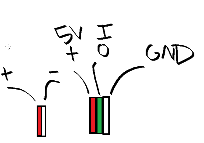
There's 5 wires. https://i.imgur.com/NoipLPt.png
 cedar mountain
I see. It's not immediately obvious how those are wired up. Possibly the two powers and two grounds are just shorted together at the connector. Do you happen to have a multimeter to test them?
lusty grail
Yes but I have no idea how to use a multimeter
pine bramble
Hi all, I am having problems trying to enter some temperatures in an array. I'm doing it with the Gemma M0 on arduino, it turns out that they don't write exactly, apparently I have the code right, but sometimes it reads the data size correctly and sometimes it ignores it. Could you give me some help please. c'''
char datos[] = "\0";
char minimum[] = "1";
char maximum[] = "30";
char numero[]="\0";
void setup() {
// put your setup code here, to run once:
}
void loop() {
//lee la tamperatura;
int temp = 28;
int j=0;
int k=strlen(datos);
sprintf(numero,"%d",temp);
delay(1000);
strcat(numero,"_");
j=strlen(numero);
Serial.println(numero);
delay(5000);
Serial.println(k);
datos[k] = numero[0];
datos[k+1] = numero[1];
datos[k+2] = numero[2];
Serial.println(strlen(datos));
Serial.println(datos);
delay(5000);
}'''
Hi all, I am having problems trying to enter some temperatures in an array. I'm doing it with the Gemma M0 on arduino, it turns out that they don't write exactly, apparently I have the code right, but sometimes it reads the data size correctly and sometimes it ignores it. Could you give me some help please.
c```
char datos[] = "\0";
char minimum[] = "1";
char maximum[] = "30";
char numero[]="\0";
void setup() {
// put your setup code here, to run once:
}
void loop() {
//lee la tamperatura;
int temp = 28;
int j=0;
int k=strlen(datos);
sprintf(numero,"%d",temp);
delay(1000);
strcat(numero,"_");
j=strlen(numero);
Serial.println(numero);
delay(5000);
Serial.println(k);
datos[k] = numero[0];
datos[k+1] = numero[1];
datos[k+2] = numero[2];
Serial.println(strlen(datos));
Serial.println(datos);
delay(5000);
}```
cedar mountain
pine bramble
c```
char datos[] = "\0";
char minimum[] = "1";
char maximum[] = "30";
char nume...
You'll want to define a maximum size for your arrays, like char datos[20], so there is room to write additional characters in to them.

 cedar mountain
lusty grail
Yes but I have no idea how to use a multimeter
cedar mountain
lusty grail
Yes but I have no idea how to use a multimeter
The easiest way is to put it into continuity-check mode, which will probably have an icon like an audible speaker. If it beeps when you touch the probes together, you're good. Then you can test pairs of wires to see if they are really the same or not.
Thanks @stable forge ... much more informative. 👍
pine bramble
The weird thing is that the array length varies between 5 and the true length which is increasing as I add data. This is the output of the Serial Monitor.
23:46:37.606 -> 28_
23:46:42.595 -> 5
23:46:42.595 -> 8
23:46:42.595 -> 2828_28_
23:46:48.603 -> 28_
23:46:53.600 -> 8
23:46:53.600 -> 5
23:46:53.600 -> 2828_
23:46:59.588 -> 28_
23:47:04.571 -> 5
23:47:04.571 -> 11
23:47:04.571 -> 2828_28_28_
23:47:10.594 -> 28_
23:47:15.609 -> 11
23:47:15.609 -> 5
23:47:15.609 -> 2828_
23:47:21.597 -> 28_
23:47:26.568 -> 5
23:47:26.568 -> 14
23:47:26.568 -> 2828_28_28_28_
23:47:32.568 -> 28_
23:47:37.601 -> 14
23:47:37.601 -> 5
23:47:37.601 -> 2828_
23:47:43.602 -> 28_
23:47:48.609 -> 5
23:47:48.609 -> 17
23:47:48.609 -> 2828_28_28_28_28_
23:47:54.598 -> 28_
23:47:59.599 -> 17
23:47:59.599 -> 5
23:47:59.599 -> 2828_
23:48:05.607 -> 28_
pine bramble
cedar mountain
You'll want to define a maximum size for your arrays, like `char datos[20]`, so ...
I gave the array a certain value, but it keeps doing this anyway.
tardy iron
pine bramble
I gave the array a certain value, but it keeps doing this anyway.
are you trying to make an array of multiple strings? because that's not what you've declared
cedar mountain
pine bramble
I gave the array a certain value, but it keeps doing this anyway.
Instead of doing the manual copying with [k], you should probably use strcat() to append the strings together.
pine bramble
tardy iron
are you trying to make an array of multiple strings? because that's not what you...
I have believed, that I define an arrangement and there I enter characters.
pine bramble
cedar mountain
Instead of doing the manual copying with `[k]`, you should probably use `strcat(...
with strcat made an infinite loop, I had to resend the program without strcat.
cedar mountain
pine bramble
with strcat made an infinite loop, I had to resend the program without strcat.
Well, you do seem to have an infinite loop. datos never gets cleared, only continually appended to.
pine bramble
cedar mountain
Well, you do seem to have an infinite loop. `datos` never gets cleared, only con...
if this is true, I always add 3 characters. I think there is an infinite loop or something wrong, because when I give strcat with datos it crashes.
cedar mountain
If datos keeps growing, it will probably crash when it exceeds the maximum length you declared for the array.
pine bramble
cedar mountain
If `datos` keeps growing, it will probably crash when it exceeds the maximum len...
that happens the first time, with strcat(datos,numero) it crashes in the first loop.
cedar mountain
You might try printing the length of datos first, as it might not be initialized like you expect.
pine bramble
cedar mountain
You might try printing the length of `datos` first, as it might not be initializ...
Do you think that if I give a fixed size to the array, then the characters will be copied correctly?
tardy iron
the C string API (what you're currently using) is awfully tricky to use, even for experienced programmers. maybe you should try using String instead?
cedar mountain
I'm not sure, there are a lot of ways to do this right and a lot of ways to do it wrong. The details matter, so you might want to start in the simplest steps and gradually build up to the full behavior you want.
pine bramble
tardy iron
the C string API (what you're currently using) is awfully tricky to use, even fo...
I'm not sure, there are a lot of ways to do this right and a lot of ways to do it wrong. The details matter, so you might want to start in the simplest steps and gradually build up to the full behavior you want.
yes you are right, but unfortunately defining the datos size presents me with the same problem. But I think it has to do with reading where datos is located.
Thank you very much for giving me ideas of where the problem may be.
 coarse crag
Hi I'm trying to connect adafruit logger & prop feather wing
https://www.adafruit.com/product/2796
https://www.adafruit.com/product/3988
SD cardinfo example works when logger is stand alone, but when I connect prop feather wing, I can connect the LIS3D accel but somehow my card is not recognized. Cardinfo example actually fails when Feather Wing connected.... Any suggestion?

Feather is the new development board from Adafruit, and like its namesake it is thin, light, and lets you fly! We designed Feather to be a new standard for portable microcontroller ...

The Adafruit Feather series gives you lots of options for a small, portable, rechargeable microcontroller board. Perfect for fitting into your next prop build! This FeatherWing will unlock ...
leaden walrus
are you running the same SD cardinfo example with / without the prop maker? or are you modding it somehow to try and also use the LIS3D?
coarse crag
yes same example
trying to find the root cause of problem
I have a script where I mix the 2, but it seems to me the basic cardinfo example should still work out of the box
leaden walrus
agree. don't think anything on the propmaker uses spi.
cardinfo sketch is this one?
https://learn.adafruit.com/adafruit-feather-m0-adalogger/using-the-sd-card
coarse crag
what's odd though is I can connect to LIS3DH which suggests wiring is ok
leaden walrus
that'd be over i2c, so different pins
what do you get in the serial monitor when running the cardinfo sketch with the prop maker attached?
coarse crag
* is a card inserted?
* is your wiring correct?
* did you change the chipSelect pin to match your shield or module?
and simply remove prop maker, run same sketch, and it works?
coarse crag
Card type:         SDHC
Clusters:          973584
Blocks x Cluster:  64
Total Blocks:      62309376

Volume type is:    FAT32
Volume size (Kb):  31154688
Volume size (Mb):  30424
Volume size (Gb):  29.71

Files found on the card (name, date and size in bytes):
SPOTLI~1/     2022-03-09 16:16:48
  STORE-V2/     2022-03-09 16:16:48
    C06C29~1/     2022-03-09 16:16:48
      PSID.DB       2022-03-09 16:18:04 8192
      TM~1.LIO      2022-03-09 16:16:48 0
.....
weird. how are you powering the setup?
coarse crag

 leaden walrus
i can't recreate this. works here with / without prop maker.
coarse crag
But in your opinion prop maker should not interfere? The question I'm trying to figure out, is it a hardware thing or software thing?
coarse crag
ok thx
leaden walrus
looking at photos....
(im also using a doubler fwiw)
try cleaning up the hairs. just in case one of those is shorting something.
coarse crag
ok thx
tardy iron
also, when you try without the prop maker wing, is the feather still plugged into the doubler? (good to narrow down where a possible connection problem is)
coarse crag
yes just tried it in the double and SD still found
I tried switching them around and still had problem
What's my next move? unplugging everything and testing each connection on doubler to look for shorts?
thank you @leaden walrus and @tardy iron for pitching in...
I appreciated
leaden walrus
can you post a photo of the top of the doubler with both boards removed
coarse crag
top of doubler
 coarse crag
🤬
I always tell my son to look at the picture when he does his legos... Should apply advice to self...
leaden walrus
should be like that
 coarse crag
yes I see it!! thank you so much.
leaden walrus
np. can see how that's possible. there's a lot going on with the silkscreen on that board.
can be visually confusing
cedar mountain
 Good catch...
tardy iron
yeah, i think it would work better if the header placement outlines were visually distinct, like being a heavier line weight or something?
coarse crag
As they say, sometimes the pb is between the chair and the keyboard...
livid osprey
I'd have considered a solid fill for the header placement, but I can see why they did it the way they did...
tardy iron
hm, removing the outlines from the power rail rows might be good enough to make a visual distinction between the header sizes
solemn cliff
or have one missing hole on the short side
tardy iron
solemn cliff
or have one missing hole on the short side
yeah, that's probably more robust. also requires changing more layers (and the drill pattern)
 blazing crane
Very niche thing I'm looking for, but does anyone know of very small rfid reader with a range of roughly a foot?
A lot of the readers I'm seeing online are close to the Mega in size and only have a range of like an inch or two
And ideally cheap... I need 14
 fast steppe
does anyone know of someone using easing on a servo featherwing? I am trying to migrate code from choppy-but-easy-to-write ServoEasing code to the servo featherwing. https://github.com/danner/eyesim


GitHub
Control Two Servos in a eye-like way. Contribute to danner/EyeSim development by creating an account on GitHub.
 lament basin
evening all - I have a question. I want to connect an Adafruit AHT20 board via dupont to Stemma cable to an Arduino Due. However, the Due has a TFT shield installed (mcufriend) and uses the 3V3 pin - any ideas that doesn't involve soldering?
 inland gorge
blazing crane
A lot of the readers I'm seeing online are close to the Mega in size and only ha...
inland gorge
blazing crane
A lot of the readers I'm seeing online are close to the Mega in size and only ha...
Normal RFID readers (called "HF RFID", like the NFC stuff your phone does, access control cards, etc) are near-field devices that only read up to a few centimeters. There do exist HF RFID readers that can read tags up to a meter away, but they are high-power and expensive ($1k+). At that point I'd recommend going to UHF RFID that can read up to tens of meters, but those are even more expensive and entirely different technology than HF RFID
livid osprey
lament basin
evening all - I have a question. I want to connect an Adafruit AHT20 board via d...
They did hide an extra 3.3v in the JTAG connector, but you won’t be able to interface to that with DuPont cables AFAIK.
The sensor may be low enough current draw, however, to be powered by a gpio output that stays on. I’d check the data sheets for the current limits per pin and per device.
lament basin
livid osprey
The sensor may be low enough current draw, however, to be powered by a gpio outp...
Ah so I could define a digital pin as OUTPUT, do a digitalWrite(pin, HIGH) and it might provide enough voltage to power the device? I will give it a test later
livid osprey
lament basin
Ah so I could define a digital pin as OUTPUT, do a digitalWrite(pin, HIGH) and i...
So I looked at the numbers for my curiosity, and the I/O source current max is either 3 or 15 mA, depending on the pin. https://docs.arduino.cc/hacking/hardware/PinMappingSAM3X
You probably won't have any issues with this AHT20, since the sensor itself only draws in the range of microamps. The current this module draws is mostly going to be through the pullup resistors, coming out to about 1 mA of current. For other devices, you will have to check the IC datasheet and the module schematics to confirm whether your current draw is within the safe limits of the pins you're using.
lament basin
Awesome. Thx @livid osprey, I will let you know how it goes
 magic token
Does my flexible eink display seem broken? The bottom bar never updates and all text/drawings are misaligned.
I'm using the example that comes with the library and default pin assignments. I'm also using the ThinkInk_213_Mono_M21 type for the display according to https://learn.adafruit.com/adafruit-2-13-eink-display-breakouts-and-featherwings/arduino-usage
I double checked pin assignments and everything seems ok now, but I did wire it incorrectly before (using pin 53 as epd_cd and setting srcs to -1).


Adafruit Learning System
Easy E-Paper With Built-in Memory
The screen does refresh and properly draws the border outline, but everything in the center seems misaligned. I'm using the Thinkink_mono example as well, so no code changes (besides incorrect pins mentioned above on first try)
lament basin
@livid osprey it all works. Used pin 23 for voltage and AHT20 powered up and I could read the data using the AHTX0 library. Thanks so much for your help
 tardy zealot
Anyone know how to get partial refresh working with Featherwing epaper displays?
meager fox
Hey y'all, I've got a question about adding a power switch to my Feather microcontroller. I've seen this done two ways, one where you have a switch that disconnects the battery, and one where a switch is used to tie the Enable pin to ground to disable the 3.3v regulator. If I were to go with the version that disables the 3.3v regulator and plugged it in to USB while the switch had disabled the regulator, would the LiPo charging circuit still work? Or would I potentially damage the board by having it powered but not running the regulator? I'm working on a datalogger that I'll be backpacking with, and want to occasionally recharge the battery from a battery bank over USB. I also just really don't want to damage my Feather Sense board since they've been out of stock forever and I don't have duplicates. Thanks!
north stream
meager fox
Hey y'all, I've got a question about adding a power switch to my Feather microco...
The charger chip is connected to Vbus, so switching the enable lead won't disable the charging circuit.
meager fox
north stream
The charger chip is connected to Vbus, so switching the enable lead won't disabl...
Awesome, thank you so much! What a great design. I've been loving the Feather format.
 sick mural
meager fox
Awesome, thank you so much! What a great design. I've been loving the Feather fo...
sick mural
meager fox
Awesome, thank you so much! What a great design. I've been loving the Feather fo...
same
 rose pollen
Hi I can't seem to upload any sketches to a pi pico/fresh out of the box every time I try it just says An error occurred while uploading the sketch
livid osprey
rose pollen
Hi I can't seem to upload any sketches to a pi pico/fresh out of the box every t...
Did you open the pi pico’s RPI-RP2 boot loader drive before uploading?
rose pollen
yes it just showed the html file and the index file
sick mural
What core are you using?
rose pollen
I have no idea what that means(im kinda not super smart
leaden walrus
core = board support package
what you install via Boards Manager
the pi pico uses the RP2040, which has two options
where you following a guide for the initial setup of the Arduino IDE for Pi Pico support?
north stream
rose pollen
I get this when trying to upload `Error compiling for board Raspberry Pi Pico.`
Generally if you scroll up, there will be a more detailed description of what went wrong.
leaden walrus
rose pollen
I get this when trying to upload `Error compiling for board Raspberry Pi Pico.`
turn on verbose output File>Preferences>Show verbose output during: and look for the actual error
rose pollen
it outputted this fork/exec /home/alastair/.arduino15/packages/arduino/tools/arm-none-eabi-gcc/7-2017q4/bin/arm-none-eabi-g++: no such file or directory
leaden walrus
something didn't get installed
can you link to the guide you were following for Arduino IDE setup?
leaden walrus
what OS are you using? looks like something linux based?
rose pollen
ubuntu
leaden walrus
how did you originally install the Arduino IDE? i think that file it's looking for should be part of the main install
rose pollen
I just used the download at their website
leaden walrus
which was probably a tar ball? so you just extracted that and are running it locally?
rose pollen
yes

 quartz furnace
Does anyone know if “Pushover” is no longer available? I’ve been using it for months and noticed that I hadn’t been getting messages for a few days
I don’t see it in the libraries either
 rich coral
is it possible to clear display and data buffer separately in Sharp memory display ?
display.setCursor(0,0);
display.println("test")
display.clearDisplay();
display.refresh();
this dose not work
display.setCursor(0,0);
display.println("test")
display.refresh();
delay(500)```this is a waste of time
also display.clearDisplay() is so too expensive, it leaves half a second blank on my screen
 crystal yacht
depending on the intensiveness of your script yeah it can take a second, or two, or thirty.
 ivory ridge
atmega2560 works so well
 unique tree
How to program UART in Raspberry Pi Pico using Arduino IDE? I am trying to program the

I am trying to program the RFID reader from seeed studio
north stream
unique tree
How to program UART in Raspberry Pi Pico using Arduino IDE? I am trying to progr...
The hardware serial port appears as Serial1 in Arduino, so you would just use things like Serial1.begin(9600) to set it up, and then read and write to it like any Serial object.
Note that the Pico has a second hardware serial port, but it's not enabled in the default core for it, although there are ways to configure it if you need two hardware serial ports.
unique tree
north stream
Note that the Pico has a second hardware serial port, but it's not enabled in th...
Thanks. Will try it and update back
 calm thicket
HI
I have an Adafruit ItsyBitsy NRF52840 that i put a Non-Adafruit firmware on to test a new product/service - sadly the firmware & the product / service are not suitable so i want to set the ItsyBitsy back to factory default. The manufacturer of this product has seemingly washed their hands & not only will not help me ( and others by the way ) but is now not even answering requests for help on their own forums!!
However it does not show as a drive no matter what i try to do - no led light up on the board, so i can't install CircuitPython
No serial port shows under Arduino Ide or my OS - Linux so i cant burn a bootloader using this system
Using the normal double-click the reset button does nothing
I know that this is all my responsibility but could anyone tell me if i can recover this device back to a usable state & if so how to do it please?
north stream
calm thicket
HI
I have an Adafruit ItsyBitsy NRF52840 that i put a Non-Adafruit firmware on ...
I think the manufacturer is AdaFruit. A double click on the reset button should put it in bootloader mode. https://learn.adafruit.com/adafruit-itsybitsy-nrf52840-express/troubleshooting
calm thicket
north stream
I think the manufacturer is AdaFruit. A double click on the reset button should...
thanks for the reply -
sorry i should have been clearer as i know it is an Adafruit product & unfortunate to say the double-click method is not working ,
I suspect the entire bootloader has been erased by the test firmware,,,
north stream
At that point, you'd probably have to reload it directly using SWD.
calm thicket
north stream
At that point, you'd probably have to reload it directly using SWD.
thanks i will investigate that option
Appreciate the help
pine bramble
can you use arduino mkr gps with a teensy
north stream
pine bramble
can you use arduino mkr gps with a teensy
Yes, it only needs a few signals hooked up and it's a 3.3V device.
stable forge
calm thicket
HI
I have an Adafruit ItsyBitsy NRF52840 that i put a Non-Adafruit firmware on ...
it sounds like the bootloader was replaced
you can use a J-Link to re-flash the firmware, but it's a job
see instructions in https://github.com/adafruit/Adafruit_nRF52_Bootloader/blob/master/README.md
 placid kelp
would it be possible to use the arduino TFT graphics library on a ATMega32u2 if slightly or drastically modified
north stream
The CPU architecture is fairly similar, so the likely issues are a) finding (or making) a 32U2 configuration for Arduino, and b) if the CPU has enough resources (RAM, especially) to manage it.
placid kelp
👍
 willow breach
I'm trying to use the basic arduino stepper motor from the kit to just do anything but nothing works... I've been on this for a couple days now. Should I just order another one?
here's my wiring


And the code
north stream
willow breach
I'm trying to use the basic arduino stepper motor from the kit to just do anythi...
When you say "nothing works", what happens? Do the outputs switch? How fast?
willow breach
Well I've tried wiring them to multiple different pins, I've checked whether the power source was strong enough, used multiple code files I found and nothing has worked so far. How would I be able to check the output switching? I think my multimeter wouldn't be able to keep up right?
also, only the A LED is on, the rest is never on (on the driver)
north stream
I see you're using pin 13: does that LED change intensity?
I might try putting running the code really slowly and watching the outputs with LEDs or the multimeter to see if they're switching
livid osprey
willow breach
I'm trying to use the basic arduino stepper motor from the kit to just do anythi...
Does the stepper feel like it has power when the code is running? Is it harder to turn the shaft by hand compared to when the stepper is unplugged?
Also, which stepper driver are you using? Do you have a link or part number for the stepper driver (or kit?)
willow breach
I'm using the 28BYJ-48 driver, I'll test your think right now
It seems like it's actually impossible to turn the shaft by hand right now, even when unplugged
nvm I got it
It's not any harder when it's plugged in or unplugged
livid osprey
willow breach
I'm using the 28BYJ-48 driver, I'll test your think right now
28BYJ-48 is the stepper, not the driver board. It's unusual that there's no difference between powered and not, though it's hard for me to check wiring when I don't know the board in question.
willow breach
My bad haha, this is the driver board

Elektronik und Technik bei reichelt elektronik günstig bestellen
Met het ULN2003 stappenmotor driver board kunt u eenvoudig de 28BYJ-48 stappenmotor aansturen met een microcontroller zoals de Arduino Uno. Aan één kant van de printplaat bevindt zich een 5-pins [...]
Tested the arduino itself and everything works so it's either the driver or the motor that has a problem. I'm guessing the problem is with the driver
oh strange, as soon as I plug the motor in all leds go out. Is this normal?
 obtuse wedge
guys where should I ask coding question (I'm using ESP32 on arduino environment and FreeRTOS) but I believe its just a silly bug with analog reading
livid osprey
willow breach
oh strange, as soon as I plug the motor in all leds go out. Is this normal?
No. What kind of power supply are you using?
If that's a 9V battery I'm seeing, that's probably your issue. 9V batteries are not good for high-drain applications like motors.
willow breach
livid osprey
No. What kind of power supply are you using?
9 volt battery
oh okay haha
obtuse wedge
https://gist.github.com/alexsbmagalhaes/d70abb432475c084ebefadc013e57ee5
I've made this simple analog read and for some reason what should be a boolean variable is showing integer values on serial monitor. Im using an ESP32, you may reproduce it, just upload it to your board.

you can see it here

stateSensorA should either be 0 or 1... and never assume an integer value what is goin on 👀
willow breach
livid osprey
If that's a 9V battery I'm seeing, that's probably your issue. 9V batteries are ...
when using the 5V from the arduino only the first LED is on and that's it. It never changes no matter what I do
it's definitely harder to move it around now though
should I try another source?
obtuse wedge
willow breach
should I try another source?
yes
willow breach
5V or? I don't really have anything atm but I can order something haha
actually I may have some 6V or 12V or something with like 4 AA's
obtuse wedge
show me the motor you are using
 obtuse wedge
those are nice 🙂
look:

look at "power out"... it can only source 500mA (and this would already make it hot and stuff)
you should use a separate power source for your motor driver
then I assume you are using the 9V battery right?

Most people rely heavily on 9v batteries. They use them in remotes, lamps, toys, and so much more. But they never stop to consider the…
it will source you around 600mA for some time... then it will quickly drop its voltage and current
your motor needs
wait is it a 5V motor?
it should be good
anyways, if the leds are turning off, I would assume the battery is drained
simply replace the battery with any 5V supply
Amazon.com: 5v 1a power supply
look for anything with at least 1 amp
stick with 5V, dont try to run your motor with more voltage
@willow breach did you get it?
willow breach
alright, thanks! It's a little late and I'm helping a friend out, I'll start on it tomorrow! :)
obtuse wedge
good luck
obtuse wedge
obtuse wedge
https://gist.github.com/alexsbmagalhaes/d70abb432475c084ebefadc013e57ee5
I've ma...
just to keep things flowing on the comunity, I want to tell the answer to this.
line 111 should be >= and not just >
this was causing an out of bounds array error
this was creating all sorts of tricky runtime errors
just math and attention...
 gloomy sandal
hey, I want to make a PID controller for a heating mechanism and have also watched some videos about it, but do not quite understand PID, can someone help me?
livid osprey
gloomy sandal
hey, I want to make a PID controller for a heating mechanism and have also watch...
The main idea of PID is compensating for error. Each element of PID compensates for a different source of error to maximize stability.
P is for Proportional, compensating for present error. In the case of your heater, it would be the difference between your current temperature and your target temperature.
I is for Integral, compensating for past error. If the applied heat hasn't been enough to get it up to temperature, this will tell your heater to give a bit more.
D is for Derivative, compensating for future or predicted error. it uses its current rate of change and adjusting where it's going based on that. This has no relation to your setpoint, but rather aims to stabilize the temperature where it would otherwise oscillate, or bounce between too high and too low.
That's kinda the high level. I can't offer too much more than that without more specific application-related questions, but https://en.wikipedia.org/wiki/PID_controller has a lot of useful visualizations and equations for building and tuning such a controller.
 crystal fossil
Hello, I have been combing through some C code for a while trying to figure out how to port it over to Arduino. While trying to figure out how to make a custom attachment for a laser tag gun, I stumbled upon this repository: https://github.com/izzy84075/ltx-rapidfire. This contains all of the project files required to make a custom attachment, and includes directions, but it uses a Z8 Encore! board. It appears that their code uses a custom implementation of UART and I was wondering how I would create an equivalent one in Arduino. Is it possible with the Serial() class? If anyone with some experience with this sort of thing would mind giving some pointers on this, it would be very helpful. Thanks!
 dreamy rose
Anyone know where I can download Nano RP2040 Connect eagle cad files?
 gilded swift
dreamy rose
Anyone know where I can download Nano RP2040 Connect eagle cad files?
gilded swift
dreamy rose
Anyone know where I can download Nano RP2040 Connect eagle cad files?
What do you mean? Like the footprint for the header pins or the actual board?
It’s unlikely that you’ll get the full board files, Arduino doesn’t open source all their boards
This might be the best you get
dreamy rose
@gilded swift Yes I'm looking for the full board design so I can copy/paste some of it into a custom board of mine. I know the Atmega328P nano was fully available.
I know adafruit has the feather which is open source fully in eagle cad, but it seems that for whatever reason their schematic differs from the arduino one and even after following their schematic, I seem to be having connection issues via USB for a custom RP2040 board to upload first sketch
dreamy rose
@gilded swift Yes it won't show up via USB. And I tried pressing BOOTSEL before plugging it in to PC.
Here is my schematic. Anything wrong with it?

I also have an on-board LM1117 5v -> 3.3v converter
gilded swift
Did you confirm you are getting 3.3V to the power pins?
And 1.2V out of VRegOut
1.1-1.2V
dreamy rose
Let me check. It's a bit tricky to probe it because I need to hold the pogo pins against the board when powering it.
I'm using a 10 pin tag connect that is jumped to the USB cable, so I wonder if there's USB noise or something
gilded swift
And your SPI Flash has good joints? Make sure your crystal capacitors and resistor are well soldered
dreamy rose
yes my soldering is definitely clean. I use a stencil
gilded swift
Okay
dreamy rose
So I measured 1.09v, 3.26v and 5.0v
gilded swift
Okay, that’s good
dreamy rose
Is the 1.09v ok? It's not 1.2 exactly
gilded swift
Do you have an oscilloscope?
dreamy rose
yes I do
gilded swift
It’s 1.1-1.2V and 1.09v is well within reason
Probe the crystal return path to see if you’re getting a 12MHz sine wave
In range would be 12MHz +/- the ppm range of the crystal
dreamy rose
hmm ok that's def going to be tricky to probe given I need to hold a lot of probes against the board 😅
need to jump some wires to power it on then
I can tell you that when I tried to plug an older design via SWD, it showed up on my computer and I didn't change the design
Well actually that's not true, the older design didn't have the flash chip. This one does but that's all that changed.
gilded swift
Gotcha
north stream
gloomy sandal
hey, I want to make a PID controller for a heating mechanism and have also watch...
I found this writeup informative http://brettbeauregard.com/blog/2011/04/improving-the-beginners-pid-introduction/
north stream
dreamy rose
hmm ok that's def going to be tricky to probe given I need to hold a lot of prob...
There are tools made for that https://www.elektor.com/sensepeek-pcbite-kit-incl-4x-sp10-probe-and-test-wires
calm thicket
stable forge
you can use a J-Link to re-flash the firmware, but it's a job
Many thanks for the info...
Will probably just invest in a new itsybitsy. I only have 1 with this problem so not economic to purchase j-link at this time ....
 leaden narwhal
Could the blueprints visual coding tool in unreal engine be used to generate Arduino code? ( I think it generates c++ code )
 low verge
Hi, I want to program Arduino uno board with the original avr library in VS Code. How can I do that ???
I don’t want to use the Arduino IDE but rather the avr original library
north stream
low verge
I don’t want to use the Arduino IDE but rather the avr original library
When you say "the original AVR library", do you mean the FOSS compiler chain (gcc, etc.) that Arduino uses under the hood, or the Atmel/Microchip Studio offered by the manufacturer?
low verge
north stream
When you say "the original AVR library", do you mean the FOSS compiler chain (gc...
The foss chain tool (avr-gcc, avrdude etc...) but it’s ok i found a solution
I want to know also how to set a period of a buzzer without using delay function because im using pwm and don’t want a distorted signal
north stream
My usual approach is to call millis() until the value reaches the time for the end of the period and turn the buzzer off then.
tardy iron
or if you want to get really precise, and you're already not using Arduino libraries anyway, set up a different counter to time the buzzer duration?
low verge
tardy iron
or if you want to get really precise, and you're already not using Arduino libra...
Interesting
low verge
Hi. I seems to not found any useful way to measure AC voltages using ZMPT101B around internet. Someone can help me with a useful link ?
 distant mauve
Hello, so I downloaded the Ardunio IDE app and I configured it and all and I tried using some code from github that redirects you to a youtube video. The only thing is, I keep getting an error that says, DigiKeyboard.h no such file or directory. I found a zip on github thats basically another type of keyboard and I used it but when I ask it to type chrome, it types a bunch of gibberish. I am thinking that the program may be trying to type in another language for some reason ? But I checked and it said its default to English. I would like to use the default DigiKeyboard.h but I cannot find the library for it anywhere so I cant get it to work. Thank you. I am using an Adafruit Trinket, which is basically a Attiny85
crystal yacht
Sometimes keys will come out as gibberish if the program doesn’t understand the formatting. Not necessarily another language. Post links to the GitHub and YouTube video you’re following so others can have an idea of what you’re working with. Post code examples that you’re customizing, otherwise there’s too much guess work involved to help you. No one is a mind reader.
 dense rain
Hey there! working on a a Flora Umbrella right now and was wondering if there was a place to learn how to create my own code for it! Essentially I would like to create an effect wheel instead of the colour matching part I want 3-4 effects loaded that I can cycle through by pressing the button I attached 😄 Cheers! https://learn.adafruit.com/florabrella/tools-and-supplies
 low verge
Hi, help please. I always get this error when I try to build my code on vs code I don’t know what it is

 low verge
Oh I see. How can I solve that ?
tardy iron
it's probably a bug in VS Code (or some extension). it should be quoting things correctly for the shell. to work around it, you can rename the directory to not contain an apostrophe
tardy iron
are there any good tricks for attaching a 100mil male header to the RESET_EN solder jumper on the Uno? assuming i don't want to buy a SMT header or drill holes (i don't know if the "solder"-side routing is safe to drill through in that location)
 broken tendon
dense rain
Hey there! working on a a Flora Umbrella right now and was wondering if there wa...
broken tendon
dense rain
Hey there! working on a a Flora Umbrella right now and was wondering if there wa...
https://learn.adafruit.com/u/firepixie
i reccomend firepixies tutorials specifically since so many of her projects are colorful leds (often fastLED library w/ palettes) there's probably a project here that does close to what you want (don't currently have time to look myself though)
dense rain
broken tendon
https://learn.adafruit.com/u/firepixie
i reccomend firepixies tutorials specific...
Thanks 😊 I think it’s close but I’m begining to think that Flora doesn’t have a stop current code function
broken tendon
dense rain
Thanks 😊 I think it’s close but I’m begining to think that Flora doesn’t have a...
There's no reason it cant, I had some time to dig up more info maybe this will help https://www.youtube.com/watch?v=fRXJQVdwrog
In the 5th episode of FastLED basics, we look at how run multiple patterns, and change them either on a timer or by pushing a button. We will then look at crossfading between patterns to provide a more professional look. Finally we will see how and why we might use classes to separate our patterns from each other making it easier to add more pat...
dense rain
broken tendon
There's no reason it cant, I had some time to dig up more info maybe this will h...
@broken tendon are you familiar with FASTled or is anyone else? thanks to mox ❤️ I have successfully created an effect via button wheel. I also was able to add most of the effects I want to add, however I am having difficulty adding a "TheaterChase" effect and not sure where I'm going wrong.
The pattern/effect I am trying to add: https://paste.ofcode.org/MWfsyNtGsbrUqwMYJYzegu
The code for the button wheel sketch:
https://paste.ofcode.org/K4rr9gWt6kNKren44xkmzg
I think the issue has to do with the FastLED_Neopixel instead of just FastLED but I am not sure how to convert it over.
willow breach
obtuse wedge
good luck
It didn't end up working, thanks for the help though! My driver was probably broken. Got the same motor and driver and it all works now! :)
broken tendon
dense rain
I think the issue has to do with the FastLED_Neopixel instead of just FastLED bu...
unfortunately Im terrible at code myself, just ok at finding tutorials lol
I havent had great luck trying to smush neopixel and fastLED projects together either
if it were me I would look around for fastLED sample code that does the same thing there's tons on github
this might help
https://github.com/chemdoc77/CD77_FastLED/tree/master/CD77_Chase_Demo

GitHub
Animations using the FastLED Library . Contribute to chemdoc77/CD77_FastLED development by creating an account on GitHub.
 warm narwhal
I'm making a HID usb device that is meant to be connected to 2 computers. Any idea how to implement that?
 ebon reef
I dont mean to take over the channel, but I could use some arduino help as well. I have a project that involves 63 LED strips of varying length connected to one PWM output on an arduino. The arduino is controlled by a raspberry pi that I control via VNC viewer on my desktop./laptop. My current problem is that I am trying to find the most efficient way to create some kind of structure to store the strip data, such as length and LED numbers so that they can be indexed and assigned colors to display.
Here is an image of the LED configuration and the number of each LED with the length of the strips below them not shaded

Here is the code I have been using
sorry it doesnt fit
And here is specifically the problem with the code. It should display red on all LEDs on strip 33 but it does not, instead it assigns them around strip 25ish with the second all red just a test seeing if the arduino is having any communication issues other than the code
  for (int iteration = 0; iteration < numIterations; ++iteration) {
    for (int i=0; i<Strips[33].length-1;i++)
    {
      int j = Strips[33].stripleds[i];
      leds[j] = CRGB::Red;//CHSV(random8(),255,255);//CRGB::DarkBlue; // 186,23,192 hue, saturation, value

    }
    FastLED.show();
    delay(3000);
    for (int i=0; i<NUM_LEDS;i++)
    {
      leds[i]=CRGB::Red;

    }
    FastLED.show();


    delay(1000 );
  }
} ```Here is the specific program in question with an attempt to assign Strip[33].stripleds all CSRGB::Red for display.
Hopefully thats enough information to recieve some assistance. I don't know why the program isn't recognizing the correct LED numbers for assignment, and I could use some help figuring out why that is the case.
And if theres an easier way to store the data for indexing that would be helpful to know about aswell.
sorry, Strip[33] is this one:
 north stream
low verge
Hi. I seems to not found any useful way to measure AC voltages using ZMPT101B ar...
north stream
low verge
Hi. I seems to not found any useful way to measure AC voltages using ZMPT101B ar...
Does this help? https://www.electroschematics.com/voltage-sensor/
 lusty isle
warm narwhal
I'm making a HID usb device that is meant to be connected to 2 computers. Any id...
lusty isle
warm narwhal
I'm making a HID usb device that is meant to be connected to 2 computers. Any id...
Not simultaneously - that would blatantly violate USB specifications to my knowledge. There are USB "switches" though that might be helpful
 zinc egret
@MISC you could have two separate USB devices connected to each other by a separate link, so they sent the same commands to the two hosts simultaneously
warm narwhal
I don't really have much experience in making Arduinos talk together, but double Arduino approach is what I'm hoping for
warm narwhal
lusty isle
Not simultaneously - that would blatantly violate USB specifications to my knowl...
KVM and KM switches are kinda lost art by now. I have one at home and I think that's the newest model ever released, anthough it supports only PS2
solemn cliff
some uart connection, maybe some pin to trigger the sync on interrupt. Also USB is polled by the host, so there will never be perfect sync below the polling delay, which granted might be only 1ms
(so that might not matter)
there are probably single chips that can do multiple USB (teensy ?) which I think tinyusb can do, but don't quote me on that
warm narwhal
Thanks, I'll look for this too
The easiest and cheapest way now, is to have switches that manually change pin output >:D
Although I'm afraid one of my windows PCs won't like replugging the HID so often, that where PS2 comes to shine
 hollow bloom
I've struggled with getting the ESP32V2 working with the Ultimate GPS FeatherWing for a while now. I think I've finally figured it out (or at least a hack for it). Even though RX1/TX1 are defined in adafruit_feather_esp32_v2/pins_arduino.h file, HardwareSerial is #defining them as 9&10. I tried adding a #define RX1 7 and #define TX1 8 to my code to overwrite it, but it still didn't fix it. I had to modify the HardwareSerail.cpp file directly @@ -36,7 +36,7 @@ #ifndef RX1 #if CONFIG_IDF_TARGET_ESP32 -#define RX1 9 +#define RX1 7 #elif CONFIG_IDF_TARGET_ESP32S2 #define RX1 18 #elif CONFIG_IDF_TARGET_ESP32C3 @@ -48,7 +48,7 @@ #ifndef TX1 #if CONFIG_IDF_TARGET_ESP32 -#define TX1 10 +#define TX1 8 #elif CONFIG_IDF_TARGET_ESP32S2 #define TX1 17 #elif CONFIG_IDF_TARGET_ESP32C3 Any idea why my #defines wouldn't set it correctly?
leaden walrus
what version of the ESP32 BSP are you using?
there was a bug that was recently fixed w.r.t. those pins:
https://github.com/espressif/arduino-esp32/pull/6881
and should be in latest release
hollow bloom
That would seem to fix it! I'll try that instead. Thank you!
hollow bloom
Fantastic. Moving from 2.0.3 -> 2.0.4 fixed it!!
leaden walrus
cool. weird / simple bug. pins needed to be #def'd and not consts. being const was breaking some internal preproc logic in the BSP.
dense rain
I'm trying to set up Arduino for trinket but don't understand this step as I can not find this file "Id" that I need to replace

figured it out, it was Ld not Id
north stream
Weird, I figured it would be the unix ld (short for "load") command, but for cross compilers like that, generally prefixed with the hardware and environment type like avrtiny-gcc-ld or somesuch.
 celest trout
quick question, is the adafruit ethernet2 library capable of sending HTTP requests to other servers/API's? similar to how axios JS library can send http POST and GET requests?
dense rain
Not sure if it’s the code but I’m having this really annoying white in all my test animations not sure why tho
livid osprey
dense rain
Not sure if it’s the code but I’m having this really annoying white in all my te...
Is it possible you're using RGB code for RGBW LEDs?
dense rain
Very possible how would I not do that lmao
FASTLED_USING_NAMESPACE

#define DATA_PIN    0
#define LED_TYPE    SK6812
#define COLOR_ORDER RGB
#define NUM_LEDS    44
CRGB leds[NUM_LEDS];

#define BRIGHTNESS          46
#define FRAMES_PER_SECOND  120

void setup() {
  delay(3000); // 3 second delay for recovery

  // tell FastLED about the LED strip configuration
  FastLED.addLeds<LED_TYPE,DATA_PIN,COLOR_ORDER>(leds, NUM_LEDS).setCorrection(TypicalLEDStrip);
  //FastLED.addLeds<LED_TYPE,DATA_PIN,CLK_PIN,COLOR_ORDER>(leds, NUM_LEDS).setCorrection(TypicalLEDStrip);

  // set master brightness control
  FastLED.setBrightness(BRIGHTNESS);
}


// List of patterns to cycle through.  Each is defined as a separate function below.
typedef void (*SimplePatternList[])();
SimplePatternList gPatterns = { rainbow, sinelon, bpm };

uint8_t gCurrentPatternNumber = 0; // Index number of which pattern is current
uint8_t gHue = 0; // rotating "base color" used by many of the patterns

void loop()
{
  // Call the current pattern function once, updating the 'leds' array
  gPatterns[gCurrentPatternNumber]();

  // send the 'leds' array out to the actual LED strip
  FastLED.show();
  // insert a delay to keep the framerate modest
  FastLED.delay(1000/FRAMES_PER_SECOND);

  // do some periodic updates
  EVERY_N_MILLISECONDS( 20 ) { gHue++; } // slowly cycle the "base color" through the rainbow
  EVERY_N_SECONDS( 10 ) { nextPattern(); } // change patterns periodically
}

#define ARRAY_SIZE(A) (sizeof(A) / sizeof((A)[0]))

void nextPattern()
{
  // add one to the current pattern number, and wrap around at the end
  gCurrentPatternNumber = (gCurrentPatternNumber + 1) % ARRAY_SIZE( gPatterns);
}

void rainbow()
{
  // FastLED's built-in rainbow generator
  fill_rainbow( leds, NUM_LEDS, gHue, 7);
}

void sinelon()
{
  // a colored dot sweeping back and forth, with fading trails
  fadeToBlackBy( leds, NUM_LEDS, 20);
  int pos = beatsin16( 13, 0, NUM_LEDS-1 );
  leds[pos] += CHSV( gHue, 255, 192);
}

void bpm()
{
  // colored stripes pulsing at a defined Beats-Per-Minute (BPM)
  uint8_t BeatsPerMinute = 62;
  CRGBPalette16 palette = PartyColors_p;
  uint8_t beat = beatsin8( BeatsPerMinute, 64, 255);
  for( int i = 0; i < NUM_LEDS; i++) { //9948
    leds[i] = ColorFromPalette(palette, gHue+(i*2), beat-gHue+(i*10));
  }
}```god teir reply! I think you figgured out the issue
now to figure out how to use with fast LED
livid osprey
dense rain
Very possible how would I not do that lmao
I don't have a lot (read any) of personal experience with FastLED, but I do recall the library lacked RGBW last I checked. https://www.partsnotincluded.com/fastled-rgbw-neopixels-sk6812/ might be a good read on how to add the RGBW modification to a FastLED application...?
Someone has shown me a way to control RGBW NeoPixels (SK6812 chipset) using the FastLED library and a small additional header file.
dense rain
was just reading this! thank you so much haha didnt' realize that was a thing\
IDK if this will work with the trinket though
 neat shoal
Hi 👋
I'm trying to make humidifier for my plants and I'm using
- esp-01 or 01s
- humidity sensor DHT 11
- relay to control the humidifier because it's working on 24V
my idea is to use push button on blynk app to activate the relay but i want make it on timer , when i push the button the humidifier works for 1 min then turn off . i was trying for hours but it doesn't work 🥲 .. could you help me with code if possible 😇
neat shoal
neat shoal
Hi 👋
I'm trying to make humidifier for my plants and I'm using
1. esp-01 or 0...
btw I'm not good at coding 😅
neat shoal
neat shoal
Hi 👋
I'm trying to make humidifier for my plants and I'm using
1. esp-01 or 0...
the sensor part is working without any problems...
the problems only with delaying relay aand push button
 torpid hill
neat shoal
Hi 👋
I'm trying to make humidifier for my plants and I'm using
1. esp-01 or 0...
torpid hill
neat shoal
Hi 👋
I'm trying to make humidifier for my plants and I'm using
1. esp-01 or 0...
Show me the code
 brittle atlas
Hi, I want to control a single addressable LED Strip with an Arduino. Before I start I just want to make sure I don't run in one of the two following problems:
- Since the strip runs with 12V and a Arduino with 5V I need to use a transistor/mosfet. I don't really know which to use since I don't know the polarity of this data pin, which brings me to the second problem.
- Is this strip supported by the library? I don't know the protocol of the data line. Are there any defaults?
The only thing provided is that the LEDs are 5050 and have a 'RGBIC-Chip'. I couln't find any tutorial or someone else out there that tried this before.
 livid osprey
brittle atlas
Hi, I want to control a single addressable LED Strip with an Arduino. Before I s...
livid osprey
brittle atlas
Hi, I want to control a single addressable LED Strip with an Arduino. Before I s...
- Data is almost always 5V max, despite supply voltages sometimes being higher. Try 5V signaling first, connected to the DI end of the strip. Even if it doesn't work, you shouldn't get any bad voltages coming out if its input pin so it should be fine.
- Most common single wire protocol would be the same one the neopixel uses, and a 12V chip could be a WS2811 equivalent, so try that first before getting too worried about protocol. Chances are it'll work, but you may have to test it to find out the color order. They're 3-color LEDs, so most likely standard WS2811 GRB will work just fine though.
neat shoal
torpid hill
Show me the code
#define BLYNK_PRINT Serial // Comment this out to disable prints and save space
#include <ESP8266WiFi.h>
#include <BlynkSimpleEsp8266.h>
#include <DHT.h>
// You should get Auth Token in the Blynk App.
// Go to the Project Settings (nut icon).
char auth[] = "_j0GbSujfyhQ5-xTJsK9zhnsu6ENyMN0";
// Your WiFi credentials.
// Set password to "" for open networks.
char ssid[] = "B202ALAN-2.4G";
char pass[] = "HOMEB202";
//#define DHTPIN 0 // Signal pin connected to D3 of nodemcu
#define DHTPIN 2 // Signal pin connected to GPIO2 of ESP8266-01
// Uncomment whatever type you're using!
#define DHTTYPE DHT11 // DHT 11
//const int buttonPin = V4; // the number of the pushbutton pin
//const int ledPin = 3; // the number of the LED pin
//int buttonState = 0;
DHT dht(DHTPIN, DHTTYPE);
SimpleTimer timer;
void sendSensor()
{
float h = dht.readHumidity();
float t = dht.readTemperature(); // or dht.readTemperature(true) for Fahrenheit
if (isnan(h) || isnan(t)) {
Serial.println("Failed to read from DHT sensor!");
return;
}
// You can send any value at any time.
// Please don't send more that 10 values per second.
Blynk.virtualWrite(V5, h);
Blynk.virtualWrite(V6, t);
Serial.print("Temp = ");
Serial.print(t);
Serial.print(" Humi = ");
Serial.println(h);
}
neat shoal
neat shoal
#define BLYNK_PRINT Serial // Comment this out to disable prints and save spa...
void setup()
{
Serial.begin(9600); // See the connection status in Serial Monitor
Blynk.begin(auth, ssid, pass);
dht.begin();
pinMode(3,OUTPUT);
//digitalWrite(3, HIGH);
// pinMode(ledPin, OUTPUT);
// pinMode(buttonPin, INPUT);
/*if (3,HIGH) {
delay(10000);
digitalWrite(3, LOW); // turn led off
ledOn = false;  // prevent this code being run more then once
Serial.println("Turned LED Off"); }*/
/* digitalWrite(3, HIGH); // turn the LED on (HIGH is the voltage level)
delay(1000); // wait for a second
digitalWrite(3, LOW); // turn the LED off by making the voltage LOW
delay(1000);*/
// Setup a function to be called every second
timer.setInterval(1000L, sendSensor);
}
torpid hill
Can you please format it properly? @neat shoal
```cpp
Like this, put your code in here
```
quartz furnace
Question… I have a ESP32_S2 TFT feather from Adafruit
I’ve been uploading code successfully for a few times , but now when I go to Arduino > Tools > Port it thinks it’s a “ESP32 Dev module “ 🤷🏻♂️
gilded swift
quartz furnace
Question… I have a ESP32_S2 TFT feather from Adafruit
I’ve been uploading code...
It’s because of the module on it
quartz furnace
UPDATE . I found out how to do a factory reset.. trying that now
quartz furnace
So do I need to make sure it’s correct?
Thoughts on what to do ?
I think I figured it out .. I had a bad line of code and it was crashing it .. I changed it .. trying it now
So that was it … basically I am using a NTP client to get the time .. and I did the “begin” of the client before I had it coded to connect to wifi
gilded swift
quartz furnace
So that was it … basically I am using a NTP client to get the time .. and I did ...
That’ll do it
 fallow valve
I'm thinking to use Sparkfun's pro micro as a usb keyboard and make a full sized amiga inspired keyboard but since the pins are limited due to size how I make a matrix for the keys to work?
 jaunty delta
Hello all
I have a custom nrf52820 board
I see that adafruit has a repo with a core for nRF52s
but it is for nRF52840
I would like to make a version that would work for my board
can someone give a rundown how this could be made
I need a starting point.
inland gorge
jaunty delta
I need a starting point.
My basic steps for creating a new board using an existing core:
- Fork the core in question to make your core, e.g. https://github.com/adafruit/Adafruit_nRF52_Arduino
- In Arduino, uninstall the original core if you have it installed and put this new core in "<SKETCHFOLDER>/hardware/"
- In your core, copy the section in the core's
boards.txtthat most corresponds to your board (eg. like say for instance the "feather52840" board: https://github.com/adafruit/Adafruit_nRF52_Arduino/blob/master/boards.txt) and give it a unique name like "mitkoBoard58240" or something - Create a directory in the core's
variantsdirectory for your board. This directory name must match the.board.variantvalue you've added. e.g. for the "feather52840", the variant specifier line isfeather52840.build.variant=feather_nrf52840_express - Edit the files in the
variantsdirectory to match your board. Usually this means just changingvariants.h&variants.cppwith your board's pin names to chip pin names. e.g. notice how "feather52840" sets up its pinmap and status LEDs invariant.cpp( https://github.com/adafruit/Adafruit_nRF52_Arduino/blob/master/variants/feather_nrf52840_express/variant.cpp) and defines for SPI, Flash, and Serial invariant.h(https://github.com/adafruit/Adafruit_nRF52_Arduino/blob/master/variants/feather_nrf52840_express/variant.g) - When you restart Arduino, you should see the Adafruit core with your board as an option
 coral geyser
Hey all new here. Got a question that I don’t think was asked before as I tried the message search feature here to see if anyone had. I have an SSD1327 1.5” OLED interfaced with a Huzzah32. Example sketch works fine but when I try to draw grayscale bitmap by invoking the function call display.drawGrayscaleBitmap() i get a garbled mess. I converted my bmp via a sparkfun python library to retain the grayscale and get the hex array. I’ve also read through the docs and noticed that all references to grayscale functions in the adafruit gfx lib seem to be for 8 bit and not 4 bit. Seeing as the SSD1327 lib is dependent upon the gfx library is the grayscale a function I’m not able to use? Or am I just missing something here? Much appreciated been scratching my head about this the last few evenings.
pine bramble
Hello everyone,
I am configuring an output pin to power an EEPROM, it turns out that I want it to be powered only for a couple of seconds, for that I need to set the pin high and then I need to disconnect the pin, as if it was not configured. Thanks for reading and for your ideas.
cedar mountain
pine bramble
Hello everyone,
I am configuring an output pin to power an EEPROM, it turns out...
Typically setting a pin to input mode will put it into a high-impedance state, where it's outputting neither high nor low and is essentially disconnected.
low verge
Hi. Please how could I use ZMPT101B to meseaure AC voltage ? I don’t find a good formula to get the accurate voltage.
 quartz river
Hello. I'm trying to program a PyGamer in Arduino C with the Adafruit Arcada library. It defines colors like this:
#define ARCADA_BLACK 0x0000       ///<   0,   0,   0
#define ARCADA_NAVY 0x000F        ///<   0,   0, 123
#define ARCADA_DARKGREEN 0x03E0   ///<   0, 125,   0
I'd like to use my own RGB color, but I fail to understand that format. So given three RGB values (from 0 to 255), how can I convert it to one of those values that I can use with fillCircle? It says it takes a single uint16_t for the color as a 16-bit 5-6-5 Color. I don't know what that means, but how would I convert an RGB value where each channel is from 0 to 255 into that format?
pine bramble
rrrrrggggggbbbbb
something like that. 5 red bits, six green ones and five blue ones.
There's probably a library written to make it easier to work with this system.
neat shoal
coral geyser
coral geyser
Hey all new here. Got a question that I don’t think was asked before as I tried ...
any ideas? heres the code file.
pine bramble
cedar mountain
Typically setting a pin to input mode will put it into a high-impedance state, w...
Tanks 🙂
 vast knoll
hi guys, im using as5600 magnetic encoder to read rotation from a linear actuator motor. my code is for reading value from sensor and calculate how many rotation that the motor produce (forward and backward) using ++ and -- function. when i print the value on serial print the value is printing the intended value (ranging from 0-50 for rotation) from program, but when i send the value using analog write to another arduino to check the value it becomes 0-1023 value. anyone know what did i do wrong?
low verge
Hi. I have 2 big problems
1-my UNO board doesn’t give me the same voltage in some outputs (2.9V, 4.5V, 5V) is it normal ?
2-one of the port seems to drive no current (test with a mini 5V buzzer). How is it possible ?
north stream
low verge
Hi. I have 2 big problems
1-my UNO board doesn’t give me the same voltage in som...
The outputs are not powerful and can only drive a few milliamps, so the voltage will drop (and it will stress the driver transistors) if they're connected to a low impedance load. There are various approaches to increase the drive capability, one popular one is to use the outputs to control transistors that drive the load.
 jaunty nest
The SSD1306 library has startscroll functions, can i make it clip instead of repeating when out of bounds? Want to scroll out a splashscreen
low verge
north stream
The outputs are not powerful and can only drive a few milliamps, so the voltage ...
Yes I’m using transistor to drive a relay. Even with no load connected only with my multimeter I can see these voltages drops
north stream
Are you using a bipolar transistor or a MOSFET?
low verge
Pin D2 doesn’t supply any current even to a led
north stream
You'll need a current limiting base resistor, or the transistor itself will try to pull down the pin voltage to 0.6V
low verge
north stream
You'll need a current limiting base resistor, or the transistor itself will try ...
It’s already there
A 10k resistor
north stream
Hmm. Sounds like you're doing everything right and perhaps your Uno is, as you suspected, not normal.
low verge
Yes I’m sure it’s not normal
Others pins with the same BJT config work but not the D2 pin
And I don’t know why at open circuit there are pins with less than 4V and others with 5V
north stream
Configured as outputs, with the outputs high, yes, they should be at 5V
low verge
Yes I put them all as outputs to test
low verge
north stream
Configured as outputs, with the outputs high, yes, they should be at 5V
I want my code to sound 2 times at intervals of 500ms when the relay is activated. I don’t know why it only sound one time. Can u help me please ?
 jaunty nest
do you really need this buzzer action to be nonblocking tho?
low verge
Then when the command pin of relay is high an interrupt is triggered to puts stateOnduleur at 0 again
low verge
jaunty nest
do you really need this buzzer action to be nonblocking tho?
Yes I want it to sound 1time on one action and 2 times for the other
cedar mountain
vast knoll
hi guys, im using as5600 magnetic encoder to read rotation from a linear actuato...
The analogWrite() function typically outputs a value using a PWM waveform that's high, say 20% of the time and low 80%, in order to represent a voltage that's 20% of the range. If you read that directly with an ADC, you'll typically measure either the low or the high pulse piece, getting voltage values at the extreme of the range.
Your main options would be to add some analog filtering (like an RC filter) to the output to smooth the voltage, or to send the value to the other Arduino via a digital method, like another serial port.
north stream
low verge
I want my code to sound 2 times at intervals of 500ms when the relay is activate...
I'm thinking something like this: ```arduino
static int beepcount;
static unsigned long nextbeep;
void loop()
{
unsigned long now;
now = millis();
if ((beepcount > 0) && (now > nextbeep) {
tone(BUZZER, FREQUENCE, DUREE_SON);
--beepcount;
nextbeep = now + DUREE_SON + INTERVALLE;
}
}
i just found out that the sensor is 12bit. i will use this DAC to convert it back to 12bit again after arduino nano to arduino uno but i can't find any documentation regarding to pass value from sensor to the out pin of mcp4725
 tardy iron
vast knoll
hi guys, im using as5600 magnetic encoder to read rotation from a linear actuato...
tardy iron
vast knoll
hi guys, im using as5600 magnetic encoder to read rotation from a linear actuato...
if this is an Arduino Uno doing analogRead(), that is expected, because the ADC has a 10-bit range, and the API gives you an integer
cedar mountain
vast knoll
i just found out that the sensor is 12bit. i will use this DAC to convert it bac...
That looks like an I2C interface, so you'd use the Wire library to send commands to the DAC, or an MCP4725-specific library if you have one.
vast knoll
tardy iron
if this is an Arduino Uno doing `analogRead()`, that is expected, because the AD...
the uno doesn't got program with arduino IDE, i'm connecting it to matlab simulink for a control system
tardy iron
vast knoll
the uno doesn't got program with arduino IDE, i'm connecting it to matlab simuli...
the 10-bit ADC range is a limitation of the chip. i dunno what the Matlab API for it is like: whether it gives you the raw value from the chip, or is supposed to output a floating point number, or what
vast knoll
tardy iron
the 10-bit ADC range is a limitation of the chip. i dunno what the Matlab API fo...
the DAC actually has 12bit specification and the simulink arduino interface can read a digital and analog signal
tardy iron
vast knoll
the DAC actually has 12bit specification and the simulink arduino interface can ...
i'm not quite sure what you're trying to do, then
vast knoll
cedar mountain
That looks like an I2C interface, so you'd use the `Wire` library to send comman...
yep i already have the library of the DAC but the problem is the sensor also use an i2c interface and it doesn't output the value like i intended, or maybe there's something i did wrong
tardy iron
vast knoll
yep i already have the library of the DAC but the problem is the sensor also use...
as long as the I2C bus addresses don't conflict, it should work OK (if you have the I2C commands to the DAC correct)
vast knoll
tardy iron
as long as the I2C bus addresses don't conflict, it should work OK (if you have ...
ok i'll try again, thanks for the help, also @cedar mountain
tardy iron
vast knoll
yep i already have the library of the DAC but the problem is the sensor also use...
how are you measuring the DAC output? and how does it differ from what you intend?
low verge
north stream
I'm thinking something like this: ```arduino
static int beepcount;
s...
beepcount is zero at the beginning I think ? It will not enter in the condition
north stream
Right. The idea is for the code to set beepcount to the desired number of beeps when it wants them
low verge
north stream
Right. The idea is for the code to set `beepcount` to the desired number of bee...
I just want 2 beeps after to notify that the system has switched to another source. One beep is for the first source
Do you get me ? So I’m using pin interrupts to trigger when one of these pins is high and then the sound will notify which source is set
Is there any way on arduino which tells if an input pin drops to 0 ?
north stream
I think you can configure an interrupt that way. You can use the same technique with interrupts and beepcount, just if you'll be changing the value in an interrupt service routine, you should declare the variable as volatile.
low verge
north stream
I think you can configure an interrupt that way. You can use the same technique...
Oh my god forgot about that. Let me correct that
low verge
north stream
I think you can configure an interrupt that way. You can use the same technique...
But only D2 and d3 can be used to trigger an interrupt at both falling and rising edge ?
north stream
I haven't played with interrupts on a Uno in a while, so I don't remember the details, but that might be the case.
low verge
Others pins just trigger interrupts when the state change. It’s no very usable for my case
D2 and D3 are already used for other purposes in my application
north stream
You can still make it work, just check the level in the interrupt service routine: if it's low, it was a falling change.
low verge
north stream
You can still make it work, just check the level in the interrupt service routin...
Check a level ? How to do that ?
north stream
digitalRead() or read the port variable
low verge
Sorry I don’t really know much about arduino. I use avr originals library almost all the time
low verge
north stream
`digitalRead()` or read the port variable
Oh thanks. Let me check
jaunty delta
inland gorge
My basic steps for creating a new board using an existing core:
- Fork the core ...
you are the coolest
 hollow flint
hey everyone: what is the maximum potential difference for the ESP32S2, I'm getting conflicting information. The espressIF data sheet says it's 2.5 V, while some arduino related tutorials tell me it's 3.3V
out of the gates it seems to be 2.5V based on what I get when doing an analogread(), there are a lot of bad tutorial sites out there claiming 3.3V but with "non linear" bit mapping

How to use adc channel of ESP32 board and how to measure analog voltage using analog to digital conveter of ESP32 devkit and other boards
 native dagger
I'd say go with the datasheet over a tutorial you had no hand in writing. Datasheet is 99.9% if the time a better SoT
hollow flint
for sure, just curious b/c the adafruit website is mum on either as far as I can tell https://learn.adafruit.com/adafruit-esp32-s2-tft-feather
 solemn cliff
Here is my understanding: it's a mess.
It depends on how the attenuation is setup, and the default is different for every ESP32 family. I think in short the pin can take 0-3.3V but can only measure a max of 2.5V linearly (?) when setup with max attenuation. I believe Arduino and IDF use the default reference voltage (no attenuation), which is a max voltage of 1.1V.
And Adafruit for example uses a 1/2 voltage divider on the feather to measure the battery pin, and sets the reference to 3.3V, which allows measuring 5V (2.5 divided) within the linear zone.
I am not clear on whether or not you could damage the pin by feeding it a value that is higher than what the attenuation it setup for (more than 1.1V in no attenuation mode eg)
hollow flint
@solemn cliff super helpful, thanks. long story short I guess is to not use the analog chain on an ESPX for anything important
FWIW using the ESP32 feather tft the max seems to be 2.5V out of the box based on the arduino board setup
solemn cliff
yeah, I get my information on the default in Arduino from comments made by UnexpectedMaker on his discord explaining why he chose to put a larger resistor on the light sensor on his board. He knows what he's talking about, but the Arduino mention was in passing, it might be inaccurate, or Adafruit chose different defaults in the board setup, because of how the board is wired
hollow flint
great tip. much appreciated. I won't tell you how much time I spent wondering why 1/2 of 4095 was 2590 😵💫 .
solemn cliff
but mostly, it's a mess
low verge
Hi. I set my pin as input to detect a state. Before plug-in the output of my circuit to that pin I did some tests on serial monitor to see how it works. I can see it switch at 1 and 0 alternatively. Is that normal ???
Many times at 0 and very few times at 1 even I set it to true in the initialization
solemn cliff
I assume it's floating, did you set a pull ?
tardy iron
can you show us your code?
low verge
solemn cliff
I assume it's floating, did you set a pull ?
uh i dont think so. what's it please ?
low verge
tardy iron
can you show us your code?
sure
tardy iron
also, what is the pin connected to when you're seeing this?
low verge
tardy iron
low verge
A1
sorry, my French isn't very good. what pin are you reading, what line of the code is reading it/printing the value, and what are you expecting to see?
low verge
tardy iron
sorry, my French isn't very good. what pin are you reading, what line of the cod...
i deleted the monitor serie sorry
i'm reading pin A1.
tardy iron
low verge
i'm reading pin A1.
OK, it looks like you've set PC1 as an input. Arduino Uno has A1 on PC1, which you've set to input in initialisation_ADC() (i assume you're using an Uno? if not, which board?). i don't see anything that sets a pullup on PC1, so you're going to be reading random electrical noise if you don't have anything connected to A1.
low verge
tardy iron
OK, it looks like you've set PC1 as an input. Arduino Uno has A1 on PC1, which y...
I set both PC0 (A0) and PC1 (A1) as inputs
That’s the the variable which stores the state of that A1 pin

I test it here
tardy iron
low verge
I set both PC0 (A0) and PC1 (A1) as inputs
you're also using a mixture of Arduino API calls and explicit port manipulation. it's a little confusing to read, and it requires extra care so that your direct manipulation doesn't conflict with what the Arduino API is doing. in this case, i think it happens not to interfere in a way that you care about
low verge
Here is its declaration. It’s set as true at the beginning so it will normally execute the first condition only
 tardy iron
low verge
I set both PC0 (A0) and PC1 (A1) as inputs
tardy iron
low verge
I set both PC0 (A0) and PC1 (A1) as inputs
it looks like you've set neither of them to have a pullup, so you should expect to read random digital values if they're disconnected
low verge
What’s that pull-up ? Sorry I’m not very familiar with arduino
solemn cliff
a pull is an internal resistor that causes the input pin to have a default value of high or low (depending on the direction of the pull). You would do something like that for example: pinMode(A1, INPUT_PULLUP);
low verge
I just want to test if the pin works correctly before connecting my circuit on it
tardy iron
or PORTC |= _BV(PC1) if you want to do it via direct port manipulation (setting a port bit high will turn on the pullup of a pin if it's set as input)
solemn cliff
well it is correct to have a floating value when not connected and no pull is set
you don't need a pull if the other side drives the pin high or low all the time
low verge
So the resistor help adjust the impedance right ?
solemn cliff
you usually chose a pull based on the signal you expect. A button that connects to GND would use a pull up, so that the input is high when the button is not pressed, and low when the button connects the pin to GND (with lower resistance than the pullup)
tardy iron
low verge
So the resistor help adjust the impedance right ?
kind of. normally, a digital input has an extremely high impedance, because probably has a CMOS buffer. but if you enable a pullup, it's a 50kOhm or so resistor to VCC (on the Arduino Uno)
low verge
I want to test a signal. It will be at 5V or 0V depending on some parameters.
Thanks to y’all.
When I will connect my circuit to that pin it will be necessary to set the pull-up ???
tardy iron
it depends on how your circuit is driving it. if your circuit always outputs a definite voltage at reasonably low impedance, you might not need a pullup enabled on that pin. though if there is a connector involved, you might want to think about how you want to handle the case of accidental disconnection
low verge
Hi. Can someone provide me a good ressource for current measurement using the ZMCT103c module ? Look like the arduino community don’t use it
 north stream
low verge
Hi. Can someone provide me a good ressource for current measurement using the ZM...
north stream
low verge
Hi. Can someone provide me a good ressource for current measurement using the ZM...
It looks like it provides an analogue output, so presumably you'd just hook that to an analog input
tardy iron
the datasheet should give you enough information for that. you'll probably want the datasheet for the actual board you're using, as well as for the current transformer itself
jaunty nest
What exactly do you need tho? Thats the first google result https://electropeak.com/learn/interfacing-zmct103c-5a-ac-current-transformer-module-with-arduino/ ^^
low verge
Thanks
coral geyser
Alrighty so my quest for drawing grayscale bitmaps on the SSD1327 continues. I’ve been able to draw grayscale bitmaps by manually entering pixel by pixel information into the arrays. But I have found a new problem which is that I can’t seem to get a bit mask working. Looking in the gfx library I can see that one of the four variations of display.drawGrayscaleBitmap() includes a 1 bit mask to determine if a pixel is set or unset. But upon using the hex codes in the library I get varying results and missing pixels. Is there something I’m missing in the documentation or am I just making a big goof. Hours of googling and what not seems like not many people have used the SSD1327 successfully or with arduino. Anyone have any recommendations?
pine bramble
Hello, today I received a package from Ebay with the following content: "Adafruit CP2102N Friend USB to Serial Converter Datarate 3Mbps USB-C 5335"
My problem: Unfortunately I can't upload sketches to my Arduino Mega 2560 via USB.....
Hier ein Paar bilder zu meinem Problem


There some pictures to my problem ^^ sorry for the german text :p
i use these drivers
 crystal yacht
noticed the red/white wire isn't soldered, is it making good contact? do you have rx to tx and tx to rx?
can you post your code?
low verge
Hi. I don’t know why my screen show this garbage. What’s that ?
 crystal yacht
post your code. gibberish test is sometimes created by bad output function or even incorrect baud rate.
low verge
crystal yacht
post your code. gibberish test is sometimes created by bad output function or ev...
My PC is off. Outage here
But it’s the basic lcd call
The basic code of the LCD is literally
``ˋliquidCrystal lcd = (A2, A3, 0, 1, 11, 12, 4, 5, 6, 7);
void setup
lcd.begin (16, 2);
loop
It basically send messages and variables
lcd.clear()
lcd.print (battery)
lcd.setCursor (0, 1)
lcd.print(« Batterie activated«) ˋ`ˋ
crystal yacht
how to post code in adafruit discord #welcome message
delete lcd.print(« Batterie activated«) and see if lcd.print (battery) is the cause, then do the opposite, trouble shoot it by taking away a print to find the culprit.
pine bramble
@crystal yacht avrdude: stk500v2_getsync(): timeout communicating with programmer
coral geyser
coral geyser
Alrighty so my quest for drawing grayscale bitmaps on the SSD1327 continues. I’v...
Alrighty so my quest for drawing grayscale bitmaps on the SSD1327 continues. I’ve been able to draw grayscale bitmaps by manually entering pixel by pixel information into the arrays. But I have found a new problem which is that I can’t seem to get a bit mask working. Looking in the gfx library I can see that one of the four variations of display.drawGrayscaleBitmap() includes a 1 bit mask to determine if a pixel is set or unset. But upon using the hex codes in the library I get varying results and missing pixels. Is there something I’m missing in the documentation or am I just making a big goof. Hours of googling and what not seems like not many people have used the SSD1327 successfully or with arduino. Anyone have any recommendations? Heres some snipets of code static const unsigned char CursorGraphic [] PROGMEM{ //0 1 2 3 4 5 6 7 8 9 10 11 12 13 14 15 0, 0, 0, 0, 0, 0, 0, 0, 0, 0, 0, 0, 0, 0, 0, 0, //0 0,15,15, 0, 0, 0, 0, 0, 0, 0, 0, 0, 0, 0, 0, 0, //1 0,15,15,15, 0, 0, 0, 0, 0, 0, 0, 0, 0, 0, 0, 0, //2 0, 0,15,15,15, 0, 0, 0, 0, 0, 0, 0, 0, 0, 0, 0, //3 0, 0, 0,15,15,15, 0, 0, 0, 0, 0, 0, 0, 0, 0, 0, //4 0, 0, 0, 0,15,15,15, 0, 0, 0, 0, 0, 0, 0, 0, 0, //5 0, 0, 0, 0, 0,15,15,15, 0, 0, 0, 0, 0, 0, 0, 0, //6 0, 0, 0, 0, 0, 0,15,15,15, 0, 0, 0, 0, 0, 0, 0, //7 0, 0, 0, 0, 0, 0, 0,15,15,15, 0,15, 0, 0, 0, 0, //8 0, 0, 0, 0, 0, 0, 0, 0,15,15,15, 0, 0, 0, 0, 0, //9 0, 0, 0, 0, 0, 0, 0, 0, 0,15,15, 0, 0, 0, 0, 0, //10 0, 0, 0, 0, 0, 0, 0, 0,15, 0, 0,15, 0, 0, 0, 0, //11 0, 0, 0, 0, 0, 0, 0, 0, 0, 0, 0, 0,15, 0, 0, 0, //12 0, 0, 0, 0, 0, 0, 0, 0, 0, 0, 0, 0, 0,15,15, 0, //13 0, 0, 0, 0, 0, 0, 0, 0, 0, 0, 0, 0, 0,15,15, 0, //14 0, 0, 0, 0, 0, 0, 0, 0, 0, 0, 0, 0, 0, 0, 0, 0 //15 }; static const unsigned char CursorGraphicMask [] PROGMEM{ // 0 1 2 3 4 5 6 7 8 9 10 11 12 13 14 15 0xFE, 0xFE, 0xFE, 0xFE, 0xFE, 0xFE, 0xFE, 0xFE, 0xFE, 0xFE, 0xFE, 0xFE, 0xFE, 0xFE, 0xFE, 0xFE, //0 0xFE, 0x01, 0x01, 0xFE, 0xFE, 0xFE, 0xFE, 0xFE, 0xFE, 0xFE, 0xFE, 0xFE, 0xFE, 0xFE, 0xFE, 0xFE, //1 0xFE, 0x01, 0x01, 0x01, 0xFE, 0xFE, 0xFE, 0xFE, 0xFE, 0xFE, 0xFE, 0xFE, 0xFE, 0xFE, 0xFE, 0xFE, //2 0x7F, 0x7F, 0x01, 0x01, 0x01, 0xFE, 0xFE, 0xFE, 0xFE, 0xFE, 0xFE, 0xFE, 0xFE, 0xFE, 0xFE, 0xFE, //3 0x7F, 0x7F, 0x7F, 0x01, 0x01, 0x01, 0xFE, 0xFE, 0xFE, 0xFE, 0xFE, 0xFE, 0xFE, 0xFE, 0xFE, 0xFE, //4 0x7F, 0x7F, 0x7F, 0x7F, 0x01, 0x01, 0x01, 0xFE, 0xFE, 0xFE, 0xFE, 0xFE, 0xFE, 0xFE, 0xFE, 0xFE, //5 0x7F, 0x7F, 0x7F, 0x7F, 0x7F, 0x01, 0x01, 0x01, 0xFE, 0xFE, 0xFE, 0xFE, 0xFE, 0xFE, 0xFE, 0xFE, //6 0x7F, 0x7F, 0x7F, 0x7F, 0x7F, 0x7F, 0x01, 0x01, 0x01, 0xFE, 0xFE, 0xFE, 0xFE, 0xFE, 0xFE, 0xFE, //7 0x7F, 0x7F, 0x7F, 0x7F, 0x7F, 0x7F, 0x7F, 0x01, 0x01, 0x01, 0xFE, 0x01, 0xFE, 0xFE, 0xFE, 0xFE, //8 0x7F, 0x7F, 0x7F, 0x7F, 0x7F, 0x7F, 0x7F, 0x7F, 0x01, 0x01, 0x01, 0x7F, 0x7F, 0x7F, 0x7F, 0x7F, //9 0x7F, 0x7F, 0x7F, 0x7F, 0x7F, 0x7F, 0x7F, 0x7F, 0x7F, 0x01, 0x01, 0x7F, 0x7F, 0x7F, 0x7F, 0x7F, //10 0x7F, 0x7F, 0x7F, 0x7F, 0x7F, 0x7F, 0x7F, 0x7F, 0x01, 0x7F, 0x7F, 0x01, 0x7F, 0x7F, 0x7F, 0x7F, //11 0x7F, 0x7F, 0x7F, 0x7F, 0x7F, 0x7F, 0x7F, 0x7F, 0x7F, 0x7F, 0x7F, 0x7F, 0x01, 0x7F, 0x7F, 0x7F, //12 0x7F, 0x7F, 0x7F, 0x7F, 0x7F, 0x7F, 0x7F, 0x7F, 0x7F, 0x7F, 0x7F, 0x7F, 0x7F, 0x01, 0x01, 0x7F, //13 0x7F, 0x7F, 0x7F, 0x7F, 0x7F, 0x7F, 0x7F, 0x7F, 0x7F, 0x7F, 0x7F, 0x7F, 0x7F, 0x01, 0x01, 0x7F, //14 0x7F, 0x7F, 0x7F, 0x7F, 0x7F, 0x7F, 0x7F, 0x7F, 0x7F, 0x7F, 0x7F, 0x7F, 0x7F, 0x7F, 0x7F, 0x7F, //15 };
function call is made with the regular display.drawGrayscaleBitmap(xmove,ymove,CursorGraphic,CursorGraphicMask,16,16);followed by the display.display(); and a clear display command to clear the buffer after.
inside of the gfx library If I go to the gfx.cpp I can see the values for setbit and clrbit which is how I got the hex values in the first place // Bitmask tables of 0x80>>X and ~(0x80>>X), because X>>Y is slow on AVR const uint8_t PROGMEM GFXcanvas1::GFXsetBit[] = {0x80, 0x40, 0x20, 0x10, 0x08, 0x04, 0x02, 0x01}; const uint8_t PROGMEM GFXcanvas1::GFXclrBit[] = {0x7F, 0xBF, 0xDF, 0xEF, 0xF7, 0xFB, 0xFD, 0xFE}; #endif
north stream
coral geyser
Alrighty so my quest for drawing grayscale bitmaps on the SSD1327 continues. I’v...
I'm not sure you can use a 1 bit mask to accurately determine the pixel state of a grayscale (more than one bit per pixel) image
coral geyser
@north stream am I just reading the docs wrong?
 north stream
Huh, I'm not quite sure how to interpret that. I'd probably look at the code.
coral geyser
north stream
Huh, I'm not quite sure how to interpret that. I'd probably look at the code.
thats where the hex values for the set and clr bit were obtained from the github repository. The weird thing is that there is only one example sketch and the majority of the functions and examples dont show how to invoke them without going into the specific header which is only specific to that sketch. Plus I havent found any examples of where people draw greyscale bitmaps. Which Ironically is the entire reason I bought this screen
livid osprey
coral geyser
inside of the gfx library If I go to the gfx.cpp I can see the values for setbit...
I imagine those GFXsetBit and GFXclrBit values are just bitmasks in a lookup table. The drawGrayscaleBitmap() function has a 1-bit mask, meaning each byte should define the opacity of 8 pixels. You can think of each pixel you want to write as a 1 and each pixel you want ignored as a 0.
The datatype is uint8_t, so you may have to group the bits into chars. If you're manually entering your bitmask, it'd probably look like this:
 static const unsigned char CursorGraphicMask [] PROGMEM{
   //   01234567    89ABCDEF
      0b00000000, 0b00000000, //0
      0b01100000, 0b00000000, //1
      0b01110000, 0b00000000, //2
      0b00111000, 0b00000000, //3
      0b00011100, 0b00000000, //4
...etc...                   };
Thank you I’ll have a deeper look at this later got to go to work but thank you for the suggestion will be trying later.
coral geyser
livid osprey
I imagine those GFXsetBit and GFXclrBit values are just bitmasks in a lookup tab...
you were right thank you so much!
quartz furnace
Hello looking for help with a I2C Device on a Adafruit ESP32-S2 FTF feather using I2C
https://wiki.dfrobot.com/Gravity_Speech_Synthesis_Module_SKU_DFR0760
Wiki: The Speech Synthesis module supports Chinese and English, and uses I2C and UART two communication modes, gravity interface.
Doesn’t seem to like the ESP32 S2 I2C port ?
From reading the documents.. the feather has the same post on the qwiic and on the feather pins
The speech module can also do SofwareSerial but S2 doesn’t support that correct?
I have done a I2C scan and it does show connected 0x40
So wiring must be okay
quartz furnace
I think I have that done correctly, I used the start up from the I2c scan that Adafruit provided for the S2
quartz furnace
No sound on the speech player … they don’t relay have good code written for seeing errors
And sadly the board does not have a power led
quartz furnace
Yep only unmarked all of the ss.Set
The speaker is 3.3 or 5v so that shouldn’t be a problem
The mAh is just around 100.. that should be okay
leaden walrus
try adding these lines before ss.begin()
pinMode(TFT_I2C_POWER, OUTPUT);
digitalWrite(TFT_I2C_POWER, HIGH);
delay(500); // adjust as needed
have you gotten that device to work with other arduino boards?
quartz furnace
I can try an uno
Hmmm so in trouble shooting… I tried a PIR breakout that has an LED… does not light when connected to qwiic … odd how the I2c scan would have worked though
leaden walrus
what i2c scan sketch were you using?
leaden walrus
#if defined(ARDUINO_ADAFRUIT_FEATHER_ESP32S2_TFT)
  pinMode(TFT_I2C_POWER, OUTPUT);
  digitalWrite(TFT_I2C_POWER, HIGH);
#endif
Yep!
leaden walrus
essentially same thing
quartz furnace
With a delay
leaden walrus
the PIR breakout LED comes on when connected to UNO?
leaden walrus
powering via 5V?
quartz furnace
Yep
quartz furnace
The speech device says 3.3 or 5v .. I can try to go to Feather pins right on the board
leaden walrus
the PIR sensor is 5v only? or is it OK with 3v?
quartz furnace
Pir is 3.3 or 5 …from Microcenter it’s a KeysStudio remake as inland
leaden walrus
seems weird it didn't light up then
try connecting directly to the 3V pin on the feather
 quartz furnace
Will try in a second or two
quartz furnace
Well I know the I2c / qwiic port is okay .. I tired another I2c board …. Going to get something else for the speech module …
 alpine olive
Hey... looks like Feather Express nrf52840 (not Sense) is using 790uA in poweroff mode, even with empty sketch? What gives? Is it something on the PCB (it has QSPI flash + neopixel + a 100k res bridge + 3 more leds + charging circuit, not to mention LDO and DCDC etc) should I attribute it to quesicent currents of parts? I'm powering it from the 3V port.
north stream
The only things hooked to the 3.3V net are the CPU itself, the flash chip, the NeoPixel, and the voltage regulator. I'm not sure what you mean by "poweroff mode" here, as I don't see how an empty sketch would put the CPU into power-down.
alpine olive
I basically call systemOff(button, 0); which runs NRF_POWER->SYSTEMOFF = 1
by empty sketch I mean nothing else is running as this is the first line in the code, without initializing anything
I also tried copying and running all board_teardown code (from boards.h) but it had no effect
north stream
Hmmm. I don't know a lot about that chip, but I'm guessing it shuts down the chip's power supply. However, the NeoPixel and flash chip would still be powered, and their input pins might float to a voltage that causes things to conduct, in addition to their idle power draw. And the regulator chip may absorb some current on its output pin. Figuring out which ones are drawing power would be somewhat tricky, involving sensitive test equipment and probably soldering.
alpine olive
yeah I'll probably end up using the heat gun a bit to figure it out
north stream
If the flash chip and NeoPixel seem like they're drawing a lot of power, it might be worth adding pull-down resistors on their input pins to keep them from floating into an active (and therefore power-drawing) region. If the regulator is drawing power and you intend to just power the board directly, you could disconnect or remove it.
alpine olive
tried shutting down QSPI_CS (which didn't seem to do anything, but could be hard to verify as the pin's not exposed directly) had no effect
north stream
Good idea, may as well try programmatic things before breaking out the hot air
fallow valve
Okay I'm wonder if this is possible
Can one Pin on the Pro Micro control both a ROW and COL of a Keyboard matrix?
gilded swift
I’m going to say no, not without using another pin to control a mux
fallow valve
Well there's a video to get it one pin to control it - the board I've generated uses switching diodes to control the matrix
gilded swift
Share the video?
fallow valve
https://www.youtube.com/watch?v=kVw6kPSJJfw - in my generated board it's using SMD Switching Diodes

You can download the library and sketch from my blog here:
http://experimentaltechnik.com/matrix-keypad-pin-reduction/
Good and cheap Arduinos and sensors: http://goo.gl/bzOsTm
on this board generated from http://keyboard-tools.xyz/ it used Diodes and this amiga inspired keyboard has 23 columns too much to use a leo in this case without using a handmade shield (which I wish to avoid unless use a ribbon cable of some sort to make it work
 gilded swift
Ah they’re using analog
They made a resistor ladder which gives different voltage values that the ADC can read and you can assign to a keypad input
In that case, sure. That is a valid way to do a keyboard
I’m not sure if you could provide enough variance to a single analog pin for it to be reliable. Maybe use 3-4 analog pins
fallow valve
well this one is harder as I noticed the Amigs 1200's keyboard lacks serial input - I'm basically making an Amiga 1200 to run a Rasberry pi OS and emulate Amiga using Amiberry
I could use Two Pro micros and talk to each other using their TX and RX Pins and use the second to finish up the matrix
gilded swift
My guess is you could probably do 12 keys total on one ADC pin without worrying about voltage variance giving the wrong value.
fallow valve
I'll be using Sparkfun's Pro micro which is a micro version of the Arduino Leo
gilded swift
Right, it has the ATMega32u4 which has a 10-bit ADC
5V gives you the value of 1023, 0V gives you 0, 12 steps in between gives ~85 between each step. Which is pretty narrow but doable
10 steps would give you more between each ladder step
fallow valve
so how I can control all 23 colums if I done rows and cols on one pin which using switching diodes instead of Resistors
gilded swift
I don’t think you could do all 23 to one pin. I don’t think the pro micro ADC has enough resolution to do that
10-12, 16 would definitely push it. But probably not more than that
fallow valve
using two pro micros to control Amiga's numpad would be silly as I have to connected if I can't make the two talk to each other
gilded swift
You could make them talk
Lots of systems use multiple microcontrollers to handle tasks asynchronously
You could set up one pro micro as a SPI child and one as a SPI parent and communicate that way
fallow valve
I could connected most of the Colums into one row and then make the pro micro talk to the other one to finish the matrix
gilded swift
That’s one way to do it
Have you considered maybe using something with a better ADC that is in the pro micro format?
What's smaller than a Feather but larger than a Trinket? It's an Adafruit ItsyBitsy M4 Express featuring the Microchip ATSAMD51! Small, powerful, with a ultra fast ATSAMD51 Cortex ...
Adafruit has a board in the same form factor but with an cortex M4 SAMD51
fallow valve
nope the way the Keyboard tools site did it was about six rows and 23 col
gilded swift
I mean, obviously you can go the route that they suggest if it works. I’m just not personally convinced it will work for that many rows/col into one 32u4
I only suggest a board with a better ADC which would allow you to handle more rows/col
Same form factor as the pro micro
jaunty nest
Can i somehow use the string directly for the SSD1306 library?
When i use it directly:
display.println("Welcome");
display.println("█");
display.display();
it outputs weird.
When i use
display.println("Welcome");
display.write(219); // █ ascii char
display.display();
it works fine.


Any way to use the string instead of writing the chars one by one?
Maybe converting it somehow or change the project files encoding or something? ^^ sorry
using arduino framework in platformio on a raspberry pico w
I know i can do display.println("\xDB"); but i wonder if i somehow can use the "visible" one directly
fallow valve
I'll do two Pro Micros I'm only gonna do it for my keyboard until then
 spice sparrow
Hey, anyone got any idea how to use RS-422 with an uno? Found this sheild: https://store-usa.arduino.cc/products/rs422-rs485-shield-for-arduino-uno?selectedStore=us
But I'm unsure about the actual hookup. I'm trying to use this stepper motor: https://novantaims.com/mdriveplus/mdi1-nema-14-programmable-motion-control-ip20/
so I need to be able to send and receive signals. The stepper has a RX+, RX-, TX+, TX- for comms, where would they connect on the shield?
I looked at RS 485 boards (MAX485 modules) which are easier to use, but according to what I've read, RS 485 only allows for a half duplex connection which is not preferable

Arduino Online Shop
Some RS485 shields for the Arduino are not suitable for professional use, because they come without galvanic isolation between the RS485 bus and the Arduino. Without such isolation, it's possible to damage the Arduino or cause a malfunction of the device due to the large distances of an RS485 bus. Furthermore, a full-d


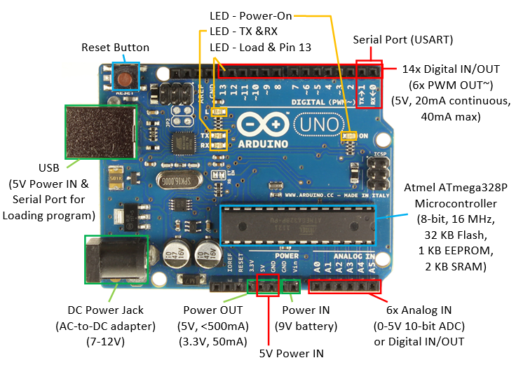 fallow valve
What's one way to translate key pressed to code needed for Ardiuno?
gilded swift
Usually you compare row + col combinations to pin point the key pressed if in a matrix
You have a 0 coming in to indicate no key press, and a key press changes the appropriate column and row pins to a 1.
fallow valve
well the FS-uae is confusing
Amiga Left A = Page Down or Right Menu / Right Windows key.
Amiga Right A = Left Menu / Left Windows key. (right ctrl for amiberry linux)
if I knew if the position is 1 for right context menu or not
how I can tell it use Ctrl right and not ctrl left?
gilded swift
You might have Ctrl R and Ctrl L on individual pins without being matrix’d
fallow valve
left control is gonna be Amiga Control - I have Amiberry set to right ctrl = right Amiga key so right ctrl can act as the left Amiga key on my handmade usb keyboard once I have the First Pro Micro controlling the Numpad
how I'll do it the First pro micro (for Numpad) and the Second one will control the remaining (someone suggested it one does the numpad and the other on Arduino Reddit)

So I'll have to write the code that the first one will send to the second one
here's my plan
Right Pro Micro = Numpad matrix
Left Pro Micro = rest of the Matrix
 nova spire
Hi, I have a question about the esp 32 qt py. I am a bit of a beginner. I wanted to see what the vbat and gnd panels on the bottom of the microcontroller does. I have linked a webpage here: https://learn.adafruit.com/adafruit-qt-py-esp32-pico/pinouts . Thanks in advance.
 leaden walrus
VBAT pads - On the back of the board are two pads labeled + and - (ground). These are the battery input pads with diode protection for external battery packs from 3V to 6V input.
that's the general description. is there something else you were looking for?
nova spire
Yeah
I am a bit of a beginner.
I wanted to understand is this a way in which I can hook a battery up to the microcontroller?
or is this a way I can hook a load (like an led or a motor) up to the microcontroller?
fallow valve
here it is right is the Numpad part and the left is the rest of the keys - I've got them connected via their Serial pins - can the usb power both for both if it's connected on their serial pins?
 leaden walrus
it's for connecting a battery
nova spire
oh okay
leaden walrus
one of the options for powering, so an input
nova spire
gotcha
fallow valve
okay what I wish to know if I connect the ardiuno's serial pins together does both need their own usb or it can power up them both without a need for usb?
gilded swift
fallow valve
okay what I wish to know if I connect the ardiuno's serial pins together does bo...
You could probably power both off the USB of one by connecting the 5V pin on one to the other, and ground to ground
Pro micro might have a specific Vin pin
fallow valve
pro micro's is VCC
gilded swift
Okay, yeah just 5V to VCC
fallow valve
is this correct? it said on a site the one Rx needs to goto TX and the other TX goes into the other's TX making sure it's current so I don't damage the micro's

https://iot-guider.com/arduino/serial-communication-between-two-arduino-boards/ followed this to get their serial pins connected
Learn Serial communication between two Arduino. Transmit data between two Arduino using RX/TX lines. Learn working with Serial read and write functions.
gilded swift
Seems right
fallow valve
Wires are confusing on kicad's eschema program okay here's what connected here

once I have the PCB made and get it made.... how I make sure both micros are sending their codes to each other
like the right one sends the numpad matrix while the Rights send it to do the other keys matrix? I would love that sends their codes to each other as if it was a smaller Leo
fallow valve
like this one ardiuno gets a code and then other send it's code to the other so they both work together
fallow valve
here's the Pro Micros connected together and now the VCCs are Connected to power both

on pro micro it's Raw meaning Vin which is same thing but different name
north stream
spice sparrow
Hey, anyone got any idea how to use RS-422 with an uno? Found this sheild: https...
I suspect that board supports full duplex
 worn palm
Hey Adafruit friends. I'm having a bit of a problem getting a Huzzah32 Feather board to connect to a 64x32 LED matrix through the RGB matrix Featherwing. I'm testing using the protomatter example code, modified with the pinouts specified for the ESP32. I'm not sure how to even troubleshoot this issue and would really appreciate a nudge in the right direction.
Protomatter example code: https://learn.adafruit.com/adafruit-protomatter-rgb-matrix-library/arduino-library
Featherwing doc with ESP32 pinouts: https://learn.adafruit.com/rgb-matrix-featherwing/usage
I also saw on one of the esp32 feather docs pages that the exact analog pins that are supposed to be used as the addrPins for this use case are input only. Worried I got the wrong combination of hardware!

Adafruit Learning System
A guide to using and porting the Protomatter library to other microcontrollers

Also, please let me know if there's a more appropriate channel for this question!
 runic quarry
I can't find a better channel for this question: I have a Feather M0 WiFi that's a few years old. When I double-press the reset button, the red LED pulses slowly, but no volume gets mounted on my Mac. I don't know if this means I don't have a UF2 bootloader, or if it's just very old. In either case, is there a way to flash the latest UF2 bootloader onto this board? I'm going to see if I can find a way to do it with bossac
Hmm, I guess I have to use OpenOCD, which I suspect means I need to solder wires to the swdio and swclk pads on the bottom, right?