#general-chat
1 messages · Page 77 of 1
 violet parcel

 hasty quarry
I had a feeling that's what it meant
Usually that symbol means "proportional"
But why is it here...
violet parcel
I get so confused about how much mA a led is using if you use duty cycle on it, doesn't that reduce the actual mA per pulse vs a duty cycle of 100% ?
hasty quarry
I don't believe so
The peak is still the same, but the perceived brightness decreases
 tardy badger
Current is constant for PWM
violet parcel
But a 20mA rating on a led is not instant mA limit afaik. oh
tardy badger
So it’s always drawing whatever the circuit is limited to
LEDs are “rated” or “tested” at a certain current limit, in many cases 20mA
But it being a diode, it will draw as much as the supply allows without any current limiting resistor
violet parcel
yeah but I meant like if you dont apply the current long enough like 1 nanosecondthe current limit apply less so I thought this is what the duty cycle did when alternating between no voltage and full voltage
tardy badger
A coin cell for instance allows you to draw ~15mA max so you can safely power without a limiting resistor
Current draw is nearly instantaneous
violet parcel
since almost no limits are "instant" just like the sun damage your eye with a telescope but not if you dont look long enough
hasty quarry
Again, the way I see it is the LED always instantly draws the current you let it draw, but all PWM does is change the perceived brightness because our eyes are slow
tardy badger
Once the circuit is completed, you will see an inrush of current
violet parcel
yeah in theory. My AA are supposed to be limited to 1A but the specs shows a graph for 2C. So they can do 2A. Im sure some cells have an higher discharge rate than standard like the lithium ones
violet parcel
hasty quarry
Again, the way I see it is the LED always instantly draws the current you let it...
yeah glad to clairfy that 🙂 I guess Ill stick to turning it off constantly at 60FPS and using prime numbers between each flash so it seems 2 are on at once to the eye except they are not to reduce power use
hasty quarry
If you watched PWM in slow motion you'd see the LED go to full brightness, and off, and repeat. Wouldn't you?
violet parcel
I wonder how that is different from manually flashing it 60 times per second
tardy badger
In theory, you can switch an LED on and off as fast as you can change DC level to the LED
The rise time is fairly negligible
hasty quarry
violet parcel
I wonder how that is different from manually flashing it 60 times per second
It's not about flashing however often, PWM is about what percentage of the time is it on vs off
That's what duty cycle means
tardy badger
PWM is both a function of frequency and duty cycle manipulation
violet parcel
Like you have led 1 on every 7 ms and led 2 on every 9ms except when those are common denominators. So both seems to be on because it's under the 16ms limit of human eyes. But I wonder if that does anything better than PWM or is a waste of time
hasty quarry
tardy badger
PWM is both a function of frequency and duty cycle manipulation
This, yeah
The faster the frequency, the smoother it will be, and the duty cycle itself is the perception of "brightness" itself
violet parcel
but if I have two leds and they are never on at the same time, only giving the impression they are and both are 20mA I'll never use 40mA right and if I have 4 of them doing that Im using 20mA instead of 80mA? Or it actually takes time to not uses any mA ?
hasty quarry
Yeah you never would
If you do make sure they aren't on at the same time at any point
violet parcel
A shift register would make this even easier
hasty quarry
True
yeah I have no idea what the proportionality symbol is doing in the datasheet
I'm confused
violet parcel
because by code if Im passed a mask of 1 1 0 1 0 0 0 0 for the shift register Id rotate between 1 0 0 0 0 0 0 0 then 0 1 0 0 0 0 0 0 1 ms later and so on
sorry I got a bit carried I dont know what the symbol means either. Can you link the datasheet ?
I like to optimize leds xD
hasty quarry

Part #: 74HC595. Description: 8-Bit Serial-Input/Serial or Parallel-Output Shift Register with Latched 3-State Outputs. File Size: 248.98 Kbytes. Manufacturer: ON Semiconductor.
Oh my god, what is going on
I just copied the text from the PDF and pasted it
μA
Why is that a mu, HOW. It looks nothing like mu
tardy badger
Lol
hasty quarry
I'm so lost
Also that metric isn't what we wanted to begin with
I looked up what quiescent means because I didn't know, it's just the idle current going through the IC when it's "doing nothing"
Which now makes sense why it's minuscule, but it's not what mattered to me
violet parcel
what page is the symbol on ? Might just be the pdf drm alldatasheet uses ?
hasty quarry
It's scattered around a bit
But page 3
Maybe the datasheet doesn't provide a maximum package current because it really is just per/pin X pin count
violet parcel
hasty quarry
Maybe the datasheet doesn't provide a maximum package current because it really ...
personally I read it as the max input is (X inputs * 20mA) + 75mA
so 6*20 + 75
 lusty fossil
New friend

 whole jacinth
@hasty quarry so the TI data sheet for 74HC595 says
• Recommend output conditions
– Load currents should not exceed 35 mA per output and 70 mA total for the part
– Outputs should not be pulled above VCC
violet parcel
hum, two wires parallel to each other seems to form a capacitor 😦
Is this an issue at MCU scale ?
whole jacinth
violet parcel
Is this an issue at MCU scale ?
it can be, depending on what kind of signal you're dealing with
violet parcel
ok 😦 what issues can that cause ? surprise current ?
whole jacinth
mostly coupling noise, especially at higher speeds
violet parcel
well doesn't seem much even for a PCB:

The reality is probably worse for breadboard because of the insolator around wires but I supposed the larger distance makes up for it
violet parcel
whole jacinth
mostly coupling noise, especially at higher speeds
Higher speeds > Like a 16Mhz crystal or a 100 Mhz cortex-M0 ? Or higher speed ~ ghz like a fpga or sbc ?
whole jacinth
violet parcel
Higher speeds > Like a 16Mhz crystal or a 100 Mhz cortex-M0 ? Or higher speed ~ ...
it depends. if you really care, you can model it at a physical level (instead of at a lumped level). for stuff like 16MHz crystals, as long as you keep the traces very short, the parasitics are small enough to not need to be modeled physically
violet parcel
I also understand that will produce transients discharging the power source faster but unless one has a lot of wires together and a very low mAH battery it's not really an issue
violet parcel
whole jacinth
it depends. if you really care, you can model it at a physical level (instead of...
nah I just wanted an idea of at which crystal frequency to start caring 😄 I guess it would be more of an issue in high-voltage circuit like ham and audio
 late fulcrum
violet parcel
hum, two wires parallel to each other seems to form a capacitor 😦
late fulcrum
violet parcel
hum, two wires parallel to each other seems to form a capacitor 😦
Or an inductor. Or a transmission line. In reality, all three at once, the proportions depending on the various dimensions, dielectric constant, presence of other conductors, etc.
whole jacinth
also, the 100MHz Cortex-M0 probably has a lower-frequency crystal that it's PLL-multiplying internally to 100MHz
violet parcel
inductor are scary 😦
whole jacinth
yeah, PCB buses are transmission lines, and have to be modeled as such, if you're going fast enough
violet parcel
I dont know how to actually discharge one besides removing the power but apparently that will arc 😦
late fulcrum
You can get away with a lot when your traces are short. So there isn't a real frequency cutoff at which you have to start caring (I've done some fairly slapdash stuff at 2.4GHz and gotten away with it, as the traces were all of 4mm long).
violet parcel
Also I thought you needed a wire accross to discharge a capacitor. So if the 2 wires are parallel with no conductors between it doesnt have terminals/contacts to discharge across it ??
late fulcrum
Normally wires (and other capacitors) are connected to something. And that something can discharge them.
violet parcel
I can see that the above have a capacity of 20 pF and could screw up a nearby crystal oscillator frequency...
whole jacinth
but yeah, if you've got long parallel traces between power and ground, you've very slightly increased the capacitance of the capacitors on your rails
late fulcrum
I did a demo a while ago showing how the miniscule capacitance of a MOSFET gate would just remember the voltage on it, even which it isn't connected to anything. I should re-do that demo and film it.
violet parcel
Like if the crystal oscillator has C1 and C2 at 27pF but there is a parallel wire at 20 pF as well, that would be enough load capacitance to change the crystal frequency
late fulcrum
Yup. Normally I mount my crystals very close to the circuitry using them, to minimize issues with distributed capacitance like that.
violet parcel
serires/parallel calculation would probably be needed to determine exactly what happens though
whole jacinth
where are you getting 20pF for PCB trace capacitance?
violet parcel
The screenshot above is a calculation for 24AWG 1mm from each other
late fulcrum
And careful measurement. Normally I don't need high accuracy from a crystal, so I don't worry about a few picofarads here or there. However one project, I'm aiming for on the order of 1ppm accuracy, for that one I'm just going to used a packaged precision oscillator instead of bothering with a bare crystal.
violet parcel
it gives 20 pF
dielectric constant of 1 for air because I wanted to calculate the worst case scenario (on a breadboard)
but I guess the inductor around the wires would raise the effective dielectric constant and make it worse than 1 for breadboards
late fulcrum
Worst case would be higher, as many materials have a higher dielectric constant than air. What I don't see in that calculation is the length of the wires.
whole jacinth
20pF for circular conductors. PCB traces aren't
violet parcel
late fulcrum
Worst case would be higher, as many materials have a higher dielectric constant ...
erm yeah I confused (l) in the formula for the number 1 ....
but l is the length of each conductor
late fulcrum
And l = 1?
violet parcel
no, I just thought the formula was 1/log10 of (2*distance between wires / diameter of the wires )
whole jacinth
so 1 meter long conductors in air
violet parcel
but the formula is L / log 10 of (2*distance between wires / diameter of the wires ) . I misread
Not sure which length Id need to use if it's the same wire but physically running paralel. Like the length that is actually parallel ?
whole jacinth
https://www.ti.com/lit/an/swra372c/swra372c.pdf says 2-8pF for trace plus terminal parasitics for common crystals. 20pF sounds high to me
late fulcrum
For a meter long, that seems like it's in the ballpark. Then again, a meter of straight wire has about 40nH of inductance
violet parcel
I think 10cm is more realistic so probably 1/10 of 20pF .... Didnt know it would be so complicated for pcb traces and depend on geometry...
thanks for indulging me as I learn more theory of try to make logical links between things btw 🙂
late fulcrum
10cm is 1/100 of a meter
whole jacinth
parallel PCB traces that are on the same side of the board next to each other will also have lots less parasitic capacitance than if they were on opposite sides of the board facing each other
late fulcrum
Erf, I'm wrong: it's 1/10 😊
There's a calculator here that can do parallel traces https://www.emisoftware.com/calculator/coplanar-capacitance/
violet parcel
speaking of PCB what happens if I use some youtuber PCB and have it printed and they asks questions about the grainger files since I dont know anything about PCB ? I just asks them to cancel ?
Like I literally couldnt answer any question they might have about the design or specs in the files
whole jacinth
typically, layout guidelines also suggest not having ground plane under traces that connect a crystal to the oscillator pins on a MCU, to minimize capacitance to ground
whole jacinth
violet parcel
Like I literally couldnt answer any question they might have about the design or...
tell your fab that you're working from someone else's design, and see if they're willing to advise you on that basis (though maybe they'll charge extra for that)
violet parcel
what about the strands in a wire ? Dont that produce internal capacitance in a 24 AWG or there is another formula for that (like the coaxial formula in the next section in the book)
whole jacinth
possibly, but it's small compared to the capacitance it produces in parallel with another wire
for most purposes, stranded wire is just circular wire with a slightly bumpy outline
sure, there might be a very thin oxide layer on individual strands, but it's unlikely that you're going to be modeling at that level of detail
the strands in a wire are also very likely to be at the same voltage
violet parcel
I see. At least I know how to calculate the time constant now and calculate how long I have with a charged cap...
hasty quarry
I went and in-place measured voltages across my resistor-LED pairs coming from the outputs of my 595 on the 1/8 duty cycle
Something I didn't really consider is the output voltage is a bit less than VCC actually, and this voltage drop varies by the resistor value and how many outputs are on
late fulcrum
violet parcel
speaking of PCB what happens if I use some youtuber PCB and have it printed and ...
We can help you with such questions. Note: they're Gerber files
late fulcrum
violet parcel
what about the strands in a wire ? Dont that produce internal capacitance in a 2...
As long as it isn't something exotic like Litz wire (strands are individually insulated and twisted in a particular pattern), it's not a big deal.
violet parcel
late fulcrum
As long as it isn't something exotic like Litz wire (strands are individually in...
no worry I try to stick to SMA
late fulcrum
SMA is a connector type, not a wire type?
violet parcel
I thought that too but doesnt it force the cable to be coaxial because of the pin in the middle and sma specs ?
late fulcrum
You can get SMA connectors that solder directly to PCBs too, but yes, they normally work with coax. And coax is available with both solid and stranded conductors.
Like these RF energy harvesters I built a while ago
 violet parcel
So for these inductors and sparks... they can cause accidental rf spark-gap right if the inductor induce an high-enough voltage on the switch and it arcs ? Is this an issue on a 500mA @ 5V mcu ? Could it destroy the mcu ? What if I cant use a big resistor just before the switch like because I have a led after it, capacitor/diode to absorb it ?
late fulcrum
An inductive spike can damage an MCU, yes. Normally a snubber network or flyback diode is used for protection, but normally I wouldn't drive an inductor directly with an MCU anyway, I'd have the MCU control a transistor that switches power to the inductor (and I'd still use protection circuitry to avoid having the inductive spike damage the transistor)
I've seen a simple buzzer circuit produce over a hundred volts from a 1.5V D cell.
violet parcel
I think a typical breadboard circuit wouldnt be big enough to acts as an antenna except as 1/4 or 3/4 wifi wavelength and could only really interferes with wifi but still.
Ive seen a demo of a rf spark-gap in china on youtube and they used a 9V battery and the voltage was around 1400V
late fulcrum
RF radiation isn't usually your main problem but if you get enough voltage to start arcing, you're right, a spark-gap transmitter produces very wide-band noise
violet parcel
but it would still be limited by the accidental antenna length right ? It's not like a breadboard is going to interfere with AM stations
late fulcrum
I tried powering a CCFL inverter from a variable supply to see if I could control the output voltage by varying the input voltage. I was impressed that it could provide 800V out from 1V in.
It might interfere with an AM receiver next to it on the desk, but you're probably not going to emit enough to bother your neighbors
In fact, a small portable AM receiver makes a dandy signal tracer
violet parcel
the other day you said mosfet have a limited voltage gain like 10-12 but most audio uses multi-stages mosfets to get much higher voltage. I forgot to ask about that
and then there is the principle of a tesla coil as well with multiple diodes and multiple caps
Seems like if you know enough voltage is a trivial thing with really high limits no matter the input voltage
late fulcrum
A MOSFET doesn't have voltage gain directly, it's basically a voltage controlled variable resistor. You can get quite a lot of gain out of one, but it's going to have a lot of distortion, so audio circuitry generally uses either lower gain or negative feedback to linearize response.
A Tesla coil does some interesting things with resonance to get massive voltage gains
Old night vision scopes had an amazing power supply that boosted its 1.5V cell to around 2000V to power the image converter tube
whole jacinth
high voltage is not difficult if you stick with low currents (also safer that way)
violet parcel
geiger circuits do the same too because the tubes needs like 600V as well I think
yeah but my multimeter can still die from an high voltage even if it's low current I think whereas I wont
late fulcrum
Yup. I helped a friend debug the power supply for the MightyOhm Geiger counter kit. It was a creative design.
violet parcel
so this seems important to know the voltage to not probe a circuit and lose the multimeter
whole jacinth
Cockroft -Walton multipliers and Marx generators can create ridiculously high voltages at low currents
late fulcrum
Modern digital multimeters are vulnerable to such things. The old non-electronic ones were pretty robust, as well as the fancier VTVM kinds (which can do some tricks that modern meters can't)
whole jacinth
yeah, modern compact DMMs tend to be good to 400V at most, if you're lucky
violet parcel
so what if I accidently convert that very high voltage but very low current to AC in my circuit ?
Isnt AC an issue at lower energy than DC ?
whole jacinth
for something like a MCU or digital IC, you might destroy it
late fulcrum
Converting high voltage DC to high voltage AC is difficult. The usual approach is to convert low voltage DC to low voltage AC, and then convert the AC to high voltage AC
whole jacinth
but lots of digital stuff is designed to tolerate some moderate amount of ESD
late fulcrum
It's not that AC itself is an issue, but it does offer some additional fun ways to get in trouble
violet parcel
I dont know how this work and why it converts DC to AC but this apparently convert a 9V battery to 4.5VAC:

But that might be a way to accidently gets AC in a circuit like using that mosfet wrong (I assume the mosfet is what convert DC to AC here)
late fulcrum
That's a "rail splitter" circuit. It converts 9VDC to plus and minus 4.5V DC by moving the 0V reference. It does not contain a (discrete) MOSFET, and it does not generate AC.
whole jacinth
yeah, AC means it can capactively couple, which can give you some nasty surprises that you wouldn't have at DC
violet parcel
eh btw dont worry about me I cant even convert 4.2V to 5V currently so
late fulcrum
While I could probably convert 4.2V to 5V, I rarely bother when I can just either buy a MintyBoost or disassemble a powerbank.
violet parcel
late fulcrum
That's a "rail splitter" circuit. It converts 9VDC to plus and minus 4.5V DC by...
yeah... Im kinda confused between transistor and mosfets especially when they get special names like the JFET here
whole jacinth
a JFET isn't a MOSFET (usually)
late fulcrum
It's an op-amp, while there are transistors inside, you can just treat it as a little amplifier module.
In this circuit, it's used as an impedance translator, to take the high impedance V/2 voltage divider formed by R18 and R19 into a low impedance node to be used as a 0V reference halfway between the input rails.
whole jacinth
while you could theoretically have an insulated-gate JFET, in practice that kind of thing is more commonly implemented as a depletion-mode MOSFET (which is still kind of rare)
violet parcel
late fulcrum
While I could probably convert 4.2V to 5V, I rarely bother when I can just eithe...
It's that I was going to buy one then someone said I need a cap with it, and probably other things that I dont know. Just seems easier to get a mintyboost or a buck-boost with a usb output for simplcity since most MCU have usb circuit to 3.3V. too
late fulcrum
Yeah, that's what I do. I figure I'll expend my energy designing the circuit I need and just use off-the-shelf solutions for solved problems like that.
violet parcel
(I havent read mosfet/transistor theory yet in case it wasn't obvious....)
late fulcrum
I learned on vacuum tubes, so they seem straightforward and clear. Then came bipolar transistors, which seemed mysterious and complicated for a long time but I slowly was able to wrap my head around how to use them. Then came MOSFETs, which work somewhat more like vacuum tubes, so I had an easier time with them.
There's a handy overview here https://learn.adafruit.com/transistors-101
 tardy badger
whole jacinth
typically, layout guidelines also suggest not having ground plane under traces t...
tardy badger
whole jacinth
typically, layout guidelines also suggest not having ground plane under traces t...
I don’t do this on anything less than 40MHz lol…
violet parcel
A difficulty I find is that I read about something with a lot of formulas some of them integrals.. Then I find out in real-life it's much more complicated because some types have improved properties over the base lol
Like the crystal oscillators I guess. Lot of ways to do the same thing but crystal is the best for certain uses
Or the different types of capacitor and capacity/esr tradeoffs
whole jacinth
a lot of EE makes a lot more sense if you know some basic calculus and differential equations. you don't need a full-blown diff eq course, just enough to solve some simple linear differential equations, and understand how Laplace transforms work
tardy badger
late fulcrum
I learned on vacuum tubes, so they seem straightforward and clear. Then came bi...
I recall something that stuck out to me in my VLSI class when talking about mosfets and them having triode regions similar to vacuum tubes I believe is what my professor said?
whole jacinth
(in practice, you Laplace (or Fourier) transform everything, so you rarely have to deal directly with the diff eq stuff anymore)
tardy badger
It’s been 4 years at this point so hard to remember
late fulcrum
One nice thing about The Art of Electronics, is it starts with the easy transistor model, which is good enough for most uses, then it explains the more complex and subtle characteristics, and the math behind them. But most of the time, the simple linear first-order approximation is good enough for the things I do, especially since transistor parameters are amazingly variable (for an ordinary bipolar transistor, current gain might be anywhere from 80 to 400). So most transistor circuits are designed to corral the operation of the circuit in various ways, to overcome that huge variability.
tardy badger
whole jacinth
(in practice, you Laplace (or Fourier) transform _everything_, so you rarely hav...
I’ve been reviewing Laplace and Fourier series lately. Trying to knock the rust of my math skills
late fulcrum
If I'm using transistors as switches (off or on), it's even simpler.
tardy badger
Good times trying to walk through old exams
whole jacinth
yeah, when driving transistors into switching, it's just a matter of dumping enough charge in or out of the base/gate
tardy badger
late fulcrum
If I'm using transistors as switches (off or on), it's even simpler.
I regularly use the prolific 2n2222 for handling lots of LEDs
violet parcel
I have 4 books now but art of electronics is too scientific for me. Feels like reading a phd thesis where I dont even know the formulas they are using. I see art ogf electronics kinda like feynman books for physics it's a in-depth theory reference
I go between the EE book from my university which also cover huge electric systems, practical electronics for inventors, foundations of analog and digital circuits from MIT as the 3 other books and of course adafruit learn. Seems like most of the time I can understand one of the explanation from at least 1 of the book
whole jacinth
Art of Electronics gives you enough simplified models that you don't need to deal with the diff eq stuff if you don't want to (though it helps to be comfortable with exponentials and logarithms)
tardy badger
I’m not sure there’s a way to avoid needing calculus, and diff eq definitely makes 2nd order equations more palatable
violet parcel
Oh I know but Im just starting so Id rather stick to the simple equations at first to understand or otherwise I get a mental blockage
tardy badger
Personally I’m not a huge fan of second order circuits
violet parcel
then then I understand the basics I can start looking ast integrals/second-order derivatives and/or derivatives matrixes calculus
whole jacinth
yeah, "why does the resonance equation look like that" makes a lot more sense if you know basic diff eq
tardy badger
Linear algebra is also widely applicable
whole jacinth
though you can kind of fake it with complex impedances (which are really a sneaky way to do Laplace transforms)
tardy badger
Personally, I enjoyed topics in linearity and superposition
late fulcrum
Here's a diagram from The Art of Electronics, giving the basic transistor formula, and introducing "Transistor Man". Even though it's a big thick impressive tome of over a thousand pages, it goes to a lot of trouble to present concepts in a useful way that's easy to understand.
 tardy badger
Plus solving network problems which using impedance can be very helpful for not dealing with diff eq
violet parcel
maxwell equations looks very scary 😦 like this . I dont even know how to calculate an integral past 1 integral symbol. And I didnt do numerical analysis of integrals so there are some integrals that cannot be calculated and most be estimated something I know zero about

I only did undergrad math so...
tardy badger
I prefer the simplified Maxwell equations
whole jacinth
usually you have simulation software handle doing the numerical solutions to Maxwell's equations when you need that level of detail. otherwise, you work with much more simplified models
tardy badger
Though personally, I struggle with gradients and curls
late fulcrum
While I can solve triple integrals, I don't have to very often (I'm considered the "math guy" at work, so people come to me when they run into math that's beyond them – I don't really try to hide that most of it is way simpler than they think but they still regard it as black magic)
tardy badger
Vector calc was not my strong suit
late fulcrum
But I'm with skerr with grads and curls 🙂
violet parcel
If someone starts speaking to me of quaternions and phonons they also completely lose me. There is probably some phonons involved if you make your own components in an industrial setting or quaternions with the geometry of some things
tardy badger
Visually though, this seems less daunting than triple integrals
late fulcrum
We had one project with a camera mounted on an aircraft. The telemetry gave the heading of the aircraft and the angle of the camera mount. The other programmers were put off by the complexity of determining where the camera was pointing, even after I pointed out that you can just add the two angles.
 late fulcrum
One nice thing about vacuum tubes is there are no phonons, holes, minority carriers, etc. It's just electrons.
tardy badger
I appreciate that we got cool words from the vacuum tube era like triode
late fulcrum
And tube socks!
 whole jacinth
https://wikimedia.org/api/rest_v1/media/math/render/svg/65e9593e0b80dea3f779dd509d643f203be97f5f
if you want a single Maxwell Equation (in Lorentz gauge). but that takes some knowledge of relativity to make sense of
violet parcel
yeah but even just electrons is complicated. Like if you need it you might have to get into the geometry, electron orbitals, electronegativty/electropositivity or that the heat is producing another compound (oxydation) etc
And how the electrons move around as charges accumulate vs the material it is on when a force (voltage) is applied
tardy badger
Not to mention electron spin (joking)
whole jacinth
(edit: DC) voltages don't come from nowhere. they typically occur because charge has accumulated somewhere
tardy badger
There does come a point where a lot of the complexity of like electrons is abstracted away
late fulcrum
Once the tube is made, you can skip all that. Sure, there's a lot of complexity in reducing the triple carbonate cathode coating to oxides, activation, etc., but the end result is the cathode boils off electrons to make an electron cloud (known as "space charge"), and the electrons can be attracted by positive electrodes. They're bare electrons, no oxidation, orbitals, or atomic stuff to worry about.
whole jacinth
AC voltages can come from "nowhere" due to electromagnetic waves passing through vacuum or dielectrics
tardy badger
The world is a giant inductor
violet parcel
whole jacinth
(edit: DC) voltages don't come from nowhere. they typically occur because charge...
and because protons are pullign the electrons
tardy badger
The universe, a giant inductor
late fulcrum
One thing that trips people up sometimes, is a voltage is always measured between two points. I've seen people point to a terminal on a 9V battery and say "this point is at 9 volts". But it's only 9 volts referenced to something (generally the other terminal).
tardy badger
Cool thing about protons is one of the subatomic particles that makes up a proton can exist in the proton and simultaneously be heavier than the proton
violet parcel
yeah it trips me off no matter how much I read it but seeing animation of the charges helps me understand, same with short circuits
whole jacinth
above about 100V or 1kV or so, everything is ground
late fulcrum
Once you have that concept solidly, then things like "the zero volt rail" and "common ground" are easier to understand.
tardy badger
whole jacinth
above about 100V or 1kV or so, _everything_ is ground
Even I am ground
late fulcrum
I was gobsmacked when I found out I can taste protons
whole jacinth
wait, how did you have an opportunity to discover that?
violet parcel
with enough magnetic field/energy even a vacuum is conductive 😄
like if you are next to a neutron star
tardy badger
I was amused when I found out that sour candy is just an electrico-chemical reaction
Wooo
late fulcrum

The first 1,000 people to use this link will get a 1 month free trial of Skillshare: https://skl.sh/stevemould03211
Our sense of taste is amazing. The way for detect sweet, sour, bitter, salt and savory (umami) flavours is really clever.
You can buy my books here:
https://stevemould.com/books
You can support me on Patreon here:
https://www.pa...
Finally a real answer to "can you lick the physics"
tardy badger
Citric acid is fun in that it tastes sour due to electrons bonding with taste buds
whole jacinth
oh, that seems like hydronium, not free protons
tardy badger
I hope I’m remembering that right
violet parcel
eh I think we are going too deep down the rabbit hole lol . My milestone for electronics is when I roll my first copper roll for says a transformer I think...

 violet parcel
It's crazy for me that matter is basically just particules with gap between them but yet it doesnt pass throught each other like a cheese cutter vs cheese
Like my skin appears solid at my level of magnification but at really small scale it's not a solid plane and what I think is my skin is basically a visual perception of a statistics of where the particles are
late fulcrum
Yeah, "solid" matter is mostly empty space
whole jacinth
yeah, solidity is mostly electron clouds repelling each other
tardy badger
It’s why I tell people I’m full of hot air
late fulcrum
The Star Trek alien that referred to humans as "ugly bags of mostly water" amused me.
violet parcel
I think I still know more chemistry than electronics but I never understood organic chemistry
tardy badger
There really is a deep appreciation for how incredibly complex things get as you drill down further in magnification
O chem, I’ve heard horror stories
late fulcrum
I have a weird fondness for organic chemistry
tardy badger
I very briefly dated a gal in college who was a pharmacy candidate
She said she almost quit due to that class
violet parcel
Like tomorrow if you asks me to make a compound I could still kinda figure it out with orbitals, mols and determin the formula etc . But I still cant make my own buck-down...
late fulcrum
We all start as beginners
tardy badger
This is where we have a deep appreciation for the people and companies that spent billions and years making it easier for us
violet parcel
Age is a factor too I guess. Chemistry seemed much easier to learn when I was 10-11yo
tardy badger
I couldn’t imagine having to design a custom power supply every time I wanted to make a board
violet parcel
And electronics was magic for me until 5 years ago when I started
tardy badger
It’s still magic to me and I went to university for it
violet parcel
If you asked me back then I would have said I can never understand it
late fulcrum
Yeah, my mom was a math teacher, so I got the huge advantage of learning symbolic algebra when I was three and my mind was still in the "absorb everything" phase
First you choose your rectifier...
 violet parcel
meh I only did matrix calculation when I was 4yo in kindergarden and multiply things because I stole my dad college math book and understood some of it (like the classic chapter 1 math overview since middle school)
tardy badger
Magic in that, the fact that electrons flow through a conductor creating an electromagnetic field which allows me to do things like run a display which in and of itself is microscopic LEDs working together to produce visible images..
hasty quarry
Magicwell's equations
violet parcel
I knew to add veyr small number with my fingers as a 4yo so when the book said multiplifcation was like adding a number X times it led me on a path where I could self-figure out myself how to multiply larger and larger number. Then the definition of division and so on
tardy badger
The fact that we figured out how to use incredibly complex lasers to do lithographic processing on semiconductor materials to make computer chips. Wild
violet parcel
So I started from like 2 + 2 = 4, so 2x2 is like 2 + 2. 2 x3 is like 2 +2 +2 . Then 4 x 6 is like 2 x 2 x 2 x 3 I already know how to do and so on.
late fulcrum
My grandfather had a mechanical calculator where you could see it counting up the result and physically move the carriage for each power of ten. It was a great illustration of the process.
violet parcel
I still try to reduce electronics problem to my method when I was 4 yo. Using induction basically
late fulcrum
Using induction to understand inductance. I like it!
violet parcel
Like if Im trying to solve n+1 and I have a similar example that is basically n, n imply n+1 by induction
whole jacinth
late fulcrum
My grandfather had a mechanical calculator where you could see it counting up th...
oh, Curta calculators? i have a couple. they're really neat
violet parcel
ie: my multiple leds problem is also a traffic light problem from miniature rail hobby which the internet is full off
late fulcrum
I love Curta calculators, but never saw one except in videos. This was a big desktop Monroe with an electric motor to power the gears.
violet parcel
so Knowing what IC they uses to handle it could help me. That is what I mean by solving electronic problems by induction
late fulcrum
The miniature rail people have a variable understanding, so their advice can be helpful, confusing, misleading, or all three at once.
violet parcel
and divide to conquer too as well
tardy badger
One thing that’s fascinating to me is that traffic light controllers are better managed with PLCs and some even use FPGA for really complex traffic patterns
Which is why it’s a great exercise for digital systems design labs
violet parcel
that is what this discord is for. At least it makes me asks a better question which helps to get helps
late fulcrum
Traffic light type problems are one place I like current regulated LED drivers, so it doesn't matter if your LED is a 2V red one or a 3V green one, the IC will give it the current you specify either way.
violet parcel
rather than just asking a vague I have to light 12 leds what do I do
whole jacinth
violet parcel
that is what this discord is for. At least it makes me asks a better question wh...
refining questions is a valuable and underrated skill
violet parcel
Yeah Im really really bad at it
I often get frustrated here and other discord that peoples dont understand my question
whole jacinth
it's a skill that can be learned (and to some extent, taught)
tardy badger
Good news is we’re always here to help
late fulcrum
Oh, many times I've failed to understand questions, my usual approach is to ask more questions to figure out what I'm missing
violet parcel
I uses AI NLP to help me simplify my question and to translate from french sometimes because it's easier to asks a clear question in my language
late fulcrum
Alas, I'm nearly illiterate in French
tardy badger
I took 3 semesters for French
violet parcel
late fulcrum
Oh, many times I've failed to understand questions, my usual approach is to ask ...
Im missing a lot of theory which get in the way of asking questions because I dont know the right words. This will helps me over time
late fulcrum
I took two semesters of Latin, which is helpful with French, Italian, etc. but doesn't make me anywhere near fluent
violet parcel
But for some reason I seems to understand datasheet naturally vs the other electronic theory
I dont know why
whole jacinth
(Alfheim is a germanic word, though?)
violet parcel
Alfheim is a dimension in minecraft associated with the botania mod
late fulcrum
Datasheets are intended to be clear and helpful, as they're a sales tool. Which is fortunate, as I'm also nearly illiterate in Russian, but often have need to read Russian datasheets.
whole jacinth
eventually you start to learn how to figure out the shape of what you don't know, so your unknown unknowns start to become known unknowns
violet parcel
But a lot of peoples here asks stuff that I can easily answer just from the datasheet
late fulcrum
I read Alfheim and think of things like Niflheim from Norse legends
violet parcel
And if it's not enough I started an answer you yellow-color users can complete
late fulcrum
I do appreciate you helping out!
violet parcel
and since I can understand code (my biggest strength) I can often explain the stuff in the code vs the datasheet or what to do/find simple code unless it's really complicated (like converting pure arduino registers/timers to other MCUs)
tardy badger
We’re all here to learn and help others learn what we’ve also learned
violet parcel
Yeah the iasue that will popup soon is knowing when to stop in seeking knowledge
Im a prfectionist who try to master anything I care about
Like my local library has a book on how to actually build a battery physically over 800 pages and I had to stop myself 🤣
tardy badger
Never stop learning, you’ll never learn it all so why put a limit on it?
violet parcel
1454 pages actually, Handbook of batteries / David Linden ....
violet parcel
tardy badger
Never stop learning, you’ll never learn it all so why put a limit on it?
limited lifetime, not knowing if I can still read books in the afterlife. Goal is to get as much knowledge to help in the shortterm, possibly with the pareto formula (learn 20% of theory to know how to solve 80% of my problems)
 cloud pilot

 pliant veldt
I'm trying to use a "Adafruit Optical Fingerprint Sensor" with "FTDI Serial TTL-232 USB Cable", I'm a complete newbie at Adafruit.
I have a lot of questions, which channel should I ask them on?
late fulcrum
Probably #help-with-projects unless they're Python specific ( #help-with-circuitpython ) or Arduino specific ( #help-with-arduino )
hasty quarry
So context again, I’m running 74HC595s as LED drivers and I’m afraid the overall package is tanking 130 mA or so when it should be 70 mA total (I think???)
I ran a chip at “maximum power”, all outputs high in its 1/8 duty cycle for something like 3-4 hours, and it didn’t get hot at all, nothing suspicious
So now I’m calling into question what the maximum ratings even mean
whole jacinth
hasty quarry
So context again, I’m running 74HC595s as LED drivers and I’m afraid the overall...
how are you measuring the current? and why is it 1/8 duty cycle, when the typical mode is to use the parallel outputs to drive LEDs from a serial input from a MCU?
oh, or are you using one set of shift registers to drive rows, and another to drive columns?
hasty quarry
@whole jacinth 8 shift registers, 1 per row of each layer
This is a cube
Layers are common cathode and sink into 8 MOSFETs, that part all seems fine
whole jacinth
chips will often tolerate higher than rated current at lower duty cycles, but data sheets will rarely quote those parameters for you. again, how are you measuring the current?
hasty quarry
I guess technically if the whole cube is on that’s maximum power, and it would be continuous current going through each shift
hasty quarry
whole jacinth
chips will often tolerate higher than rated current at lower duty cycles, but da...
Multimeter measurement multiplied by 8
You just made me realize true maximum power would be straight up continuous current
whole jacinth
hasty quarry
Multimeter measurement multiplied by 8
sorry, i'm not understanding exactly what points you have connected, whether it's a series measurement through the DMM, or whether you're using a sense resistor
hasty quarry
All LEDs have a series resistor and I measured through one output assuming it’d be the same for all 8
Said about 1-2 mA, so 8-16 mA in truth
whole jacinth
you're probably going to get the average current for a single LED, then. an oscilloscope would give you a more accurate idea of the peak current
hasty quarry
Yeah
I guess I’ll do the same test now but at full swing because that’s what would happen when the full cube is on
If it gets hot at all I’ll reconsider my series resistances. Which is upsetting because they can get kinda dim
whole jacinth
what value are your resistors, and what's the forward voltage of your LEDs?
(and you're using 5V supply for the 595s?)
whole jacinth
so that's 24mA peak, assuming zero driver impedance on the 595s, which is likely not the case
are the 595s driving the anodes or the cathodes of the LEDs? (the drive strength seems to be asymmetric, at least on the TI parts)
hasty quarry
Anodes
And according to my measurements the outputs experience some kind of voltage drop from VCC
Not sure why that is or if that matters
whole jacinth
hasty quarry
And according to my measurements the outputs experience some kind of voltage dro...
yes, that would be the finite output impedance at work
hasty quarry
Is it super significant?
It seems to vary by resistor value and how many outputs are currently on
But barely
whole jacinth
from the TI data sheet, for each parallel output current of -6mA with VCC=4.5V, VOH=3.84V. subtracting 4.5-3.84 and dividing by 6mA gives about 100 ohms. (the negative means current out of the terminal)
whole jacinth
and the forward voltage for the LED at that current?
hasty quarry
3
whole jacinth
hm, each pin looks to be rated for 35mA, with a total of 70mA for the entire chip, so technically you're going above the absolute limit (total current) at full duty cycle
hasty quarry
But I'm not seeing absolutely anything suspicious here
No heat, no strange activity, nothing
It isn't hot at all
whole jacinth
yeah, you can probably push above the absolute limit at low duty cycles, as long as you don't average over the continuous ratings. i'd add a bit of padding to be sure
hasty quarry
I'm guessing if I really want as high current as I can get the better practice would be the buffer the outputs with good buffer chips
But then what's the point of the 595s and their buffering abilities
hasty quarry
whole jacinth
yeah, you can probably push above the absolute limit at low duty cycles, as long...
I mean right now, at full duty cycle, nothing is going "wrong"
hasty quarry
whole jacinth
from the TI data sheet, for each parallel output current of -6mA with VCC=4.5V, ...
Also I don't understand this actually
I understand that 4.5-3.84 is the voltage drop through the chip at a 6 mA output
Because of some impedances in there
whole jacinth
hasty quarry
But then what's the point of the 595s and their buffering abilities
a 74HC595 isn't exactly a high current shift register. you might want something more like https://www.adafruit.com/product/457

Add a bunch of high-power outputs to a microcontroller system with chainable shift registers. These chips take a serial input (SPI) of 1 byte (8 bits) and then output those digital bits onto ...
whole jacinth
hasty quarry
I understand that 4.5-3.84 is the voltage drop through the chip at a 6 mA output
yeah, the output stage is probably a p-channel MOSFET, which has some finite on-state resistance (that is somewhat nonlinear, depending on how the gate drive is set up, and unfortunately the TI data sheet doesn't give charts)
hasty quarry
Why not say that at 3.84 volts coming out, a series resistor will get 0.84 and go from there
(Assuming 4.5 volts VCC which is a tad off, but)
whole jacinth
ok i mistyped; it's closer to 110 ohms. but if you're measuring 19mA at full duty cycle, that's more like 44 ohms, so that's probably some nonlinearity going on. you might be stuck with manually tuning the series resistances to get higher peak current
hasty quarry
The brightness I've gotten with these 82 ohms looks good, really, my worry is with not caring about being above specs on the 595s
whole jacinth
the absolute max current specs in the data sheets are for continuous current; if your average winds up being somewhat lower than that, you're probably fine. (remember you can't draw max current from each output simultaneously, because of the max current limitation on the entire chip)
hasty quarry
Yeah the chip I'm testing has been running at what it would be doing if the entire cube was turned on at once, and nothing points at it being unhappy
And considering that I wouldn't just have the whole thing on for hours at a time, I feel okay here
Also what is a voltage clamp?

Inductive transient protection? Like... an internal flyback diode on each output?
whole jacinth
hasty quarry
Inductive transient protection? Like... an internal flyback diode on each output...
yeah, that's what it sounds like
hasty quarry
Those chips look cool
whole jacinth
i wouldn't worry about it unless you've got some really long or weird wiring to the LEDs
hasty quarry
Super strong
whole jacinth
they've got a power MOSFET on each parallel output
hasty quarry
As opposed to the 74HC595 having what?
whole jacinth
the 74HC595 seems to have a CMOS push-pull output stage, possibly with slightly higher than normal capacity than standard CMOS logic (it can also both source and sink current, unlike the TPIC6B595, which can only sink)
also sorry, i was looking at worst-case specs for the output impedance over the full temperature range. at Ta=25C, VCC=4.5V, IOH=-6mA, VOH=4.3 (typ), which gives about 33 ohms, so your measured effective impedance of 44 ohms seems reasonable
whole jacinth
hasty quarry
Inductive transient protection? Like... an internal flyback diode on each output...
yeah, take a look at the equivalent output circuit on pg 3 of the data sheet
late fulcrum
hasty quarry
I'm guessing if I really want as high current as I can get the better practice w...
Or use it as a current sink instead of a current source
hasty quarry
I don't know how that would change the current that's going through the chip
Or what exactly would that do?
late fulcrum
Instead of pulling current from the power rail, it's directing current to ground. For many circuits, this is easier to do, and can avoid that "less current when all outputs are in use" effect.
hasty quarry
Oh is that why higher power things tend to sink rather than source
late fulcrum
Yup
hasty quarry
Why is this easier though?
late fulcrum
A variety of reasons. It's easier to make good N-channel transistors than P-channel ones, the ground traces and connections are often lower impedance, for starters
hasty quarry
Only really rough guess I can make is that sourcing requires impeding and enduring a higher voltage, but sinking requires the same of less voltage on a load
whole jacinth
for the same feature size, a n-channel MOFET has a lower on-state resistance than p-channel, because (roughly) electrons move more quickly than holes
hasty quarry
late fulcrum
A variety of reasons. It's easier to make good N-channel transistors than P-cha...
Ah
hasty quarry
hasty quarry
Only really rough guess I can make is that sourcing requires impeding and enduri...
This is probably not even remotely true
But I'm actually not sure
late fulcrum
I'm not entirely sure how to even parse those phrases, so I'm not sure either.
hasty quarry
Yeah, I think I didn't word it well
whole jacinth
the voltages that matter for a high-side (p-channel MOSFET) switch are the voltage drop from the rail to the output, and what the gate drive voltage should be
hasty quarry
How are CMOS and TTL fundamentally different? I actually don't know what they really mean
whole jacinth
(for a high-side switch on a 5V shift register, the gate drive challenge doesn't matter much. for a 10kV high-side switch with control logic sitting at ground, things get a lot trickier)
hasty quarry
I feel like CMOS chips are more robust but noisier somehow?
late fulcrum
The basic difference is CMOS is (complementary) MOSFET, and TTL is bipolar. In general, TTL is more robust, but current hungry.
hasty quarry
Current hungry? Is it made of BJTs?
late fulcrum
As for noise, CMOS is higher impedance, so inputs that are also from a high impedance source are more easily perturbed. However, TTL's high current switching pulses tend to create noise.
Yes, bipolar == BJT
whole jacinth
hasty quarry
Current hungry? Is it made of BJTs?
yeah, TTL is BJTs, and they need constant current to stay switched on
hasty quarry
Oh I see
But then CMOS is really high impedance because it just needs the voltage levels to be driven
whole jacinth
true, but the gate capacitance adds up at high speeds
late fulcrum
Yeah, you could think of it that CMOS is voltage operated and TTL is current operated.
hasty quarry
Doesn't this make CMOS much more power efficient in general?
late fulcrum
But argonblue is right: you need current to charge/discharge gate capacitance
Yeah, CMOS is generally a lot more power efficient than TTL
There were a couple of intermediate families (NMOS, PMOS, and I2L) but CMOS handily beat them all out
hasty quarry
What does the "complementary" mean and how is it different from all of those?
late fulcrum
NMOS just used N-channel MOSFETs, PMOS the other way around. CMOS uses both, for nice symmetrical architecture without needing pull-up or pull-down resistors
hasty quarry
Oh, so unlike NMOS and PMOS, CMOS can both source and sink?
whole jacinth
or rather, the CMOS drive capabilities are more symmetric. TTL also had very asymmetric drive capabilities
 glad ruin
This is actually a design decision in CMOS chips due to the fact that within a given process the N-doped material is generally slightly "better" in terms of current carrying capacity. This difference is sometimes offset by making the P-channel MOSFETs in output buffers physically larger.
whole jacinth
i think in practice, based on reading data sheets, CMOS output stages are more symmetrical than TTL, but can generally still sink better than they can source
 fossil dawn
I can't decide. Without or without...🤔😆 https://www.adafruit.com/search?q=328p
 late fulcrum
If you don't mind paying for it, and square pin male headers work for your application, then it makes sense to buy it with the headers already soldered. If you want to use it with a breadboard or machine pin sockets, you probably want machine pin headers or stacking headers instead. Similarly if you want female or stacking headers, different length/color headers, etc.
fossil dawn
(I don't actually need that. And if, then I would probably buy the RP2040 propmaker feather. Just thougth the title was funny. Sorry)
 sick gust
I figured y'all would get a kick out of this meme 😄
https://www.vxthreads.net/@lucas_a_meyer/post/C17SMyvLNz7
Learning to code?
Using Python to Rotate a Box
💬 58 ❤️ 1,094
 night crescent
WE ARE LIVE! ASK AN ENGINEER! https://youtu.be/_eX5iFtMhS4

Visit the Adafruit shop online - http://www.adafruit.com
LIVE CHAT IS HERE! http://adafru.it/discord
Subscribe to Adafruit on YouTube: http://adafru.it/subscribe
New tutorials on the Adafruit Learning System: http://learn.adafruit.com/
#adafruit #askanengineer ...
 dire viper

Official Raspberry 5 case with the clear plastic fan popped out so that you can use the metal heatsink.
 tepid crane
I am new to the feather community is there a starter kit to get started?
late fulcrum
There are a few parts kits you could use with a breadboard (many come with the breadboard) and just plug a Feather into it. There's also the Crickit board that you can plug a Feather into and get an assortment of useful capabilities. It depends a lot on what you want to do. One of the early AdaBoxes was basically a Feather starter kit, but I don't think it's available any more.
 dusty citrus
ich mag züge
 tribal brook
Need some help identifying a board. It sits on a pi and allows you to plug in 4 or 5 pi zeros. I thought it was called a multiplexer but I may be wrong
 cunning frost
sounds like a cluster HAT
tribal brook
YES! thank you. exactly what i was looking for
 shadow siren
Well Calgary is at -32C with Wind chill of -47C
this is what is predicted
Wind chill values between -40 and -55 are occurring this morning and will continue through the day.
Temperatures will continue to fall through the weekend. Saturday morning and Sunday morning will be the coldest, with temperatures ranging from -40 to -48°C, and wind chill values near -55. Wind chills could even be a bit colder in open and exposed areas.
tardy badger
Yikes, that’s cold
When I lived in the alpine tundra of the upper green river valley in western Wyoming, it was pretty normal to have days where the high was going to be -20°C
It wasn’t really alpine tundra exactly where I lived but it sure felt like it lol
It was classified as a semi arid high altitude desert
Elevation of ~7000ft above sea level or ~ 2150m
 umbral phoenix
always makes me wonder why early settlers, without the benefit of our modern technology, decided to settle in places so cold
hasty quarry
I thought of something kinda dark but interesting. If we were to all disappear completely and eventually a new species of being emerged from the ruins we left behind, I kinda wonder when they'd start to think "hey, this stuff couldn't have naturally occurred, it's like someone did this"
Would they just think ruined buildings are natural formations or something? Kinda weird to think about
 patent hemlock
i imagine it would be much like modern archeology -- i've always been amazed at shows watching folks walking along a pebble-strewn terrain and literally picking out pottery shards from apparently no-where
"this is not natural"
dusty citrus
Or past archelogy
You have all kind of past discussions to explain fossils, as making up mythologic animals by randomly combining fossils
Or in case with religion driven populations, there were some arguments about extinct species, but were disregarded as going in conflict with religion reachings
patent hemlock
yep, stuff happens along the way, but it's iterative and one gets closer to a more accurate picture over time with more data: a lot of our stuff, as shown, is getting close to indestructible so it will be pretty easy to posit "this ain't natural"
dusty citrus
Considering the amount of trash that we are putting out, I wouldn't find surprising the opposite, whereas our trash becomes what's natural and viceversa /s
 raw orchid
Hi guys, when working with an OLED feather hat, should I be just clearing the display when I sleep the device to prevent burn in or actually turn it off someway (maybe the oposite of begin)
patent hemlock
raw orchid
Hi guys, when working with an OLED feather hat, should I be just clearing the di...
"just clearning" turns off all the pixels, so that prevents burn-in -- you can put some power control on it if you need to really conserve power, but i think the power consumption with the entire display black and not updating will be minimal
patent hemlock
dusty citrus
Considering the amount of trash that we are putting out, I wouldn't find surpris...
yeah, i was just thinking of copper mining in trash dumps the other day for some strange reason
raw orchid
patent hemlock
"just clearning" turns off all the pixels, so that prevents burn-in -- you **can...
What's the best way to measure power consumption of a board and its connected devices?
 fair summit
raw orchid
What's the best way to measure power consumption of a board and its connected de...
fair summit
raw orchid
What's the best way to measure power consumption of a board and its connected de...
how precise do you want to be, and is powered by USB?
raw orchid
It's powered by USB yes, but I plan on running it on battery
fair summit
you can just insert an ammeter in the battery line
fair summit
if you looking for sleep currents and the like, https://www.adafruit.com/product/5048

The Power Profiler Kit II is a standalone unit, which can measure and optionally supply currents all the way from sub-uA and as high as 1A on all Nordic DKs, in addition to external ...
raw orchid
Thank you
Question, on the LoRa enabled M0's is there a way to wait for incoming transmissions in a non-blocking way so that I can still refresh the displays and such without stopping my wait for an incoming message?
fair summit
raw orchid
Thank you
the practical test here is really to run it on battery until the battery runs down
fair summit
raw orchid
Question, on the LoRa enabled M0's is there a way to wait for incoming transmiss...
ask in #help-with-radio, but yes, I think so, do you mean with Arduino or CircuitPython?
raw orchid
fair summit
the practical test here is really to run it on battery until the battery runs do...
Would you say batteries are reliable for total power provided between charge cycles with similar enviormental conditions?
raw orchid
fair summit
ask in <#439293289259204619>, but yes, I think so, do you mean with Arduino or C...
Arduino!
fair summit
raw orchid
Would you say batteries are reliable for total power provided between charge cyc...
it's not necessarily all that accurate for a quantitative report; it is a real life test. If you are looking for some measurement to write in a data sheet, then you need to specify the operating conditions (like how often you use the radio), and take sampling measurements frequently enough not to miss current spikes
raw orchid
fair summit
it's not necessarily all that accurate for a quantitative report; it is a real l...
I didn't think of sample rate being a consideration for power measurment. Thank you
fair summit
raw orchid
I didn't think of sample rate being a consideration for power measurment. Thank ...
oh, this looks convenient: https://www.adafruit.com/product/3624
This Mini Power Meter with Voltage, Current, Watts, mAh & mWh Display (whew that is a mouth-full) is a lot like the USB In-Line Voltage and Current Meter we carry but can be used with a ...
will do cumulative power consumption

This USB In-Line Voltage and Current Meter with OLED Display is a lot like the Charger Doctor we carry - if the doctor was a talented surgeon who just lost her medical license ...
 uncut trench
fossil dawn
I can't decide. Without or without...🤔😆 <https://www.adafruit.com/search?q=32...
uncut trench
fossil dawn
I can't decide. Without or without...🤔😆 <https://www.adafruit.com/search?q=32...
You might want to pass that one on to #help-with-community
tardy badger
Guessing we had a spam raid
fair summit
tardy badger
Guessing we had a spam raid
yup, automod handled
raw orchid
fair summit
oh, this looks convenient: https://www.adafruit.com/product/3624
Ill consider this as well!
violet parcel
I wish adafruit had an esm meter
there is one on aliexpress, but I cant even find the digital chip it uses for converting galvanometer measures to an lcd
and I cant find any galvanometer chip
raw orchid
Hi, can any mod let me know which word flagged the automod in my recent post here - I worked hard to format it correctly lol
Maybe it should have gone in #help-with-arduino anyway
 rapid geode
the censorbot works in mysterious ways
violet parcel
@patent hemlock "i won't get into the specifics of GC as that is definitely out of the circuitpython arena, but ... walk before you run" => we can continue here if you wish. I merely wanted to know eheter circuitpython would have been a good choice for my project but Im willing to discuss what is outside the scope of the circuitpython channel here like my project
late fulcrum
violet parcel
I wish adafruit had an esm meter
Are you referring to an electrical stress meter? That's a fairly exotic thing. I'm also not sure what you mean by "galvanometer chip". A galvanometer is basically just a meter (sometimes used in the sense of a particularly sensitive meter): it deflects a pointer with the magnetic field of a current flowing through it. There are lots of chips that can measure current, and AdaFruit offers several of them like https://www.adafruit.com/product/4226
violet parcel
late fulcrum
Are you referring to an electrical stress meter? That's a fairly exotic thing. ...
I am refering to an esr meter to test capacitors. It use amps to amplify things and display the result on a galvanometer and must be calibrated prior to doing this. Looks like this: and there is one in the april 2014 issue of qnz@aarl except their is pure analog and detect short circuit in a capacitor. SInce this one uses an LCD surely it is possible to find a chip that would do most of the work that I can read to display it on an LCD myself or I would have to buy the thing in the screenshot
 whole jacinth
violet parcel
I am refering to an esr meter to test capacitors. It use amps to amplify things ...
whole jacinth
violet parcel
I am refering to an esr meter to test capacitors. It use amps to amplify things ...
as i mentioned before, it's quite likely that they're using a microcontroller with an onboard ADC to do the measurement, display, and LCD driving, rather than using a special-purpose chip that does all that
the flip side is that you could in principle do all that yourself, with readily available parts, once you learn the underlying methods, and figure out how to calibrate well enough for your needs
violet parcel
yeah the calibration is what I was hoping to avoid since it uses this: and that I have to redraw the whole dial on a used galvanometer using that elenco rs-500 resistor substitution box to do several calibration or similar device to see what ohms do what on the physical dial Plus it would be linear instead of a logarithmic scale. (not sure what is up with image uploads here at the moment...)
 violet parcel
I see a need to know wheter the capacitors still works especially comparing their esr rating in a batch
late fulcrum
violet parcel
I am refering to an esr meter to test capacitors. It use amps to amplify things ...
Measuring ESR is a somewhat complicated process, and fraught with issues. The usual approaches generally involve pulsing the capacitor in various ways and comparing the charge and discharge behavior, and trying to subtract out other effects (such as the capacitance itself). Displaying the result is the easy part. Most of the implementations use a microcontroller to control the process, collect the data, do the calculations, and display the results. There's usually some outboard circuitry to generate the pulses and measure the behavior.
You don't need a resistor substitution box to do a calibration, just a selection of resistors or even just a potentiometer or two that you can set to the desired values. The resistor box is just a convenience.
fair summit
raw orchid
Hi, can any mod let me know which word flagged the automod in my recent post her...
answered privately
violet parcel
late fulcrum
Measuring ESR is a somewhat complicated process, and fraught with issues. The u...
Sounds like I be better off buying a cheap one then and hoping it's sensitive enough for arduino-scale capacitors.... I thought it would be a much easier project 😦
late fulcrum
Why in particular do you want to measure ESR? You can read it off the spec sheets, and for most capacitors, it doesn't change (electolytics are the main exception).
violet parcel
I have about 200 capacitors from 2014 and I want to test them to see which ones still works
late fulcrum
Ah. If they're electrolytics, you can measure capacitance and leakage, if those are okay, the ESR probably is as well. If they're not electrolytics, they're probably fine.
dusty citrus
is it a bug because the server is so big? or a joke which I don't get 💀
late fulcrum
I see all the PFPs but yours?
So it may be an issue with your client or connectivity
violet parcel
I have the same issue I dont see my pics either or salmon profile pic
violet parcel
Im asking about it in the community channel
dusty citrus
late fulcrum
I see all the PFPs but yours?
thank you anyways tho
late fulcrum
Could just be a delay in transmitting the images. I see yours now too.
violet parcel
let me try again

 hard estuary
Discord is having media loading issues: https://discordstatus.com/
dusty citrus
late fulcrum
Could just be a delay in transmitting the images. I see yours now too.
nice
dusty citrus
hard estuary
Discord is having media loading issues: <https://discordstatus.com/>
thank you
violet parcel
late fulcrum
Ah. If they're electrolytics, you can measure capacitance and leakage, if those...
do you mean like with a multimeter ?
I know how to measure capacitance but Im not sure it can do leakage, or are you saying to inspect it visually for leakage ?
late fulcrum
You can use a multimeter for leakage, either on the resistance scale, or with a source of voltage (like a 9V battery) in series with the capacitor and the meter on a voltage scale. Then you can calculate the leakage current from the voltage by dividing by the input impedance of your multimeter (often 10MΩ). If your meter can measure capacitance, you should have all you need.
I actually have a dedicated capacitor meter, which is handy for high voltage capacitors. But since you mentioned "Arduino", I'm guessing you don't need to do any high voltage measurements with a relic like this!

Silly me, posting a picture of my antique capacitor meter was futile.
violet parcel
late fulcrum
I actually have a dedicated capacitor meter, which is handy for high voltage cap...
I dont feel safe handling high voltage yet so no 😄 In that video to build an analog esr meter dude was testing it with all sort of capacitors including 4000V one explaining the tradeoffs that are needed like some types of capacitor wont work well with the 0 to 100 ohm esr scale, and a logarithmic one would be better / a dedicated one for caps that would produced an esr between 0 to 5 etc
I find 4000V capacitors very intimidating
They said it was like 30yo as well so they keep it around if needed and regularily test it since it's very expensive to buy new
late fulcrum
One of the caps in the picture I attempted to post was made in 1928, so it's nearly a century old. Still works, too.
violet parcel
It's kinda hard for me to imagine what low-voltage electronics looked like in 1928
I suppose the line would be very blurry with electromechanical stuff and the TTL would be very high like hundreds of volts
I suppose an "arduino" back then would be a PID analog system
violet parcel
The earliest I can find are john markus books in the 1960. There are a lot of radio books from the 1920 but radios arent really logic circuit like reacting to a sensor. They are just converting electricity with coils. I suppose it would involve diodes, latches/flip-flops etc which were all invented in the 1920s
late fulcrum
Yes, electronics in those days was vacuum tube based, so often moderately high voltage. There were also electromechanical systems and the like. PID wasn't common. There's a nice article on Hackaday from 2018 about the 100th anniversary of the flip-flop, including a nice re-creation. https://hackaday.com/2018/06/04/a-100th-birthday-celebration-for-the-flip-flop/
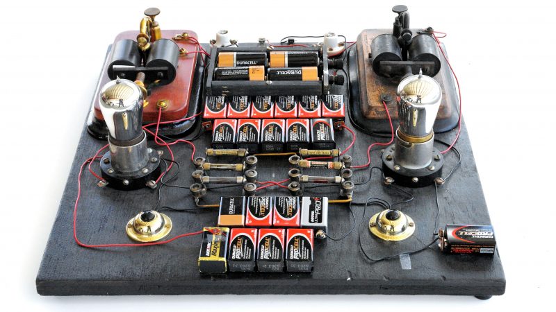
It’s easy to get caught up in the excitement of creation as we’re building our latest widget. By the same token, it’s sometimes difficult to fully appreciate just how old some of …
 brittle condor
I'm designing a pcb that is meant to receive power either from a usb port or with poe, to "merge" the two rails that then go to the 5v and 3.3v regulators do i just put in diodes like electroboom suggested or is there a better way (aka a dedicated chip)?
late fulcrum
Diodes are easy, but they have voltage drop (Schottky diodes have lower voltage drop). The fancy way is to use MOSFETs to switch the voltage, for minimum voltage drop. There are "ideal diode" chips to control this for you, but you don't always need one, like this lashup that uses a MOSFET for VBAT for the lowest voltage drop.
 brittle condor
so in this case the circuite would give "priority" to vbus right?
late fulcrum
Right
brittle condor
tho, i can see that there is still that D4 diode, could that also be removed?
late fulcrum
You could replace it with a MOSFET too, but it's a little more complicated
The LTC4415 can do it for you
 brittle condor
ohh, that's what i was looking for thx
hmmm lcsc doesn't seem to have many in stock but luckily mouser does so it seems like i'm covered, thx
late fulcrum
There are lots of chips in the PowerPath family, that's just one example. That particular one is only available in DFN and MSOP packages, don't know your constraints there.
Other vendors offer similar parts (TI's TPS2120 is one example).
brittle condor
I'm trying to make it all smd but msop so that i can still hand solder it
late fulcrum
The TI chip is offered in WCSP and VQFN, not so good for hand soldering
brittle condor
I'll use this one for now and decide if i want to switch it out later, thanks again
at least now i know what to google, it's hard to google you don't know the name of...
late fulcrum
I know that feeling. There are some projects where I've spent weeks before I discover the right terms to find what I'm looking for!
 scarlet rock
I have some very old computer and microprocessor books - Z80 and 68000 assembler and microprocessor handbooks, and a few older TI Data Books (The Power Semiconductor and The Transistor and Diode specifically) -- I don't want to trash them as I am sure they could be useful to someone.
Is there a good place for me to list them so I can get them into the hands of someone who will appreciate them?
late fulcrum
That's a good question. Those are books somebody would enjoy. Some sort of online swap shop like Craigslist or eBay? Also, many used book stores will accept donations or even pay you a little bit for them.
You can also donate to things like library sales
scarlet rock
I'm looking for good leads to vintage or retro communities also - along with these types of books, I have some very old computers that need new homes
I do realize I could eBay them, my first attempt was to find some like minded folks to give them to
(plus shipping books is pricy :/)
late fulcrum
I've had similar issues. A lot of my stuff is basically "free to good home", but finding those good homes can be tough. One person actually drove 4 hours to pick up some old computers and an oscilloscope a couple of weeks ago.
scarlet rock
nods - I just now signed up for the Vintage Computer Festival MidAtlantic mailing list ... hoping to find some like minded folks there
my reason for posting the TI books was that they may hit a nostalgia sweet spot for any of the older engineer types here :)
late fulcrum
Mid-Atlantic? I'm in Virginia...
scarlet rock
Eastern PA - Poconos and Philadelphia
late fulcrum
Ah, nice, my sweetie used to live in Bucks County
scarlet rock
oh nice! I've been in lower bucks for a long time now, only recently started to live in the Poconos area
I'm willing to drive hours if I find the person who will use this stuff to learn or make things
late fulcrum
The Trenton Computer Fest might be in range if you wanted to try that
scarlet rock
Osbourne 3, Kaypro, Compaq Luggable, TRS80 Model III and IV, Atari 520ST, Mac //gs
oh! that is definitely within range
late fulcrum
Yeah, there are people who'd want those (the person who came and got some machines from me runs a computer museum out near Pittsburgh)
scarlet rock
yea, the vintage/retro scene seems to be resurging
late fulcrum
Yup!
 scarlet rock
oh my - is that an honest to goodness S100 bus!?!
shadow siren
looks like it
scarlet rock
haven't seen one of those in ages - last time was when I was wire-wrapping an Heathkit H8
the two books I rescued
 late fulcrum
It's a Motorola bus in front, with a bus converter hiding underneath, and S-100 slots (with 4KB RAM boards in them) in the back
late fulcrum
I have the books that came with the 6800 board too
 scarlet rock
those look awesome!
violet parcel
scarlet rock
haven't seen one of those in ages - last time was when I was wire-wrapping an He...
I saw a digital copy of rca radiotron's designer handbook from 1940 by RCA today
scarlet rock
1940!
violet parcel
well the first 3 editions were made 1940 or before. 4th edition is 1960
I was able to find 3rd and 4th edition
scarlet rock
true, but still - that's even before my time
violet parcel
What is interesting is that all the circuits are redone in 4th edition it really shows transistors were invented between the two
scarlet rock
now that's so interesting - you can see the impact they had just by comparing editions
violet parcel
Like most of the circuit looks like what Im used to see vs the 1940 one that talks of radio tubes and coil tubes
scarlet rock
when I first started making gear for ham radio, the movement to transistors had become affordable to hobbyists
so all of the gear you saw in use was tube based, but all of the kits were starting to be transistor based
violet parcel
I wish I could get a ham license if only for lora and pico balloons
scarlet rock
that would definitely give you more options for the strength of signal and frequency
 tranquil swallow
scarlet rock
I'm looking for good leads to vintage or retro communities also - along with the...
tranquil swallow
scarlet rock
I'm looking for good leads to vintage or retro communities also - along with the...
https://old.reddit.com/r/RetroComputerMarket/ probably here
 violet parcel
What I like about retro books is that they get to the freaking point
The book isnt half theory at first like many modern books or vanity like youtube videos
scarlet rock
you do have a point :)
violet parcel
Like I saw one from 1964 which is like the 500 in 1 kit except you provide the components and there's no plate (so just a book) and page 4 is a circuit for voltage regulation the reader will need throught the book. Another example is soldering technique on page 5: cuz no time to waste with endless theory just get soldering 🤣
 scarlet rock
heck, now a days that would be it's own chapter, if not two
violet parcel
Wish they had used a 20$ 1MP embedded camera thought because the picture of the technique is really low definition and black and white (/joke of course)
1954 inventiveness when ones dont have amazon cheap plastic jewellery organization boxes:

caps in an ice cube tray 🤣
 scarlet rock
my mom always got mad when she found her baking trays in the basement
violet parcel
scarlet rock
when I first started making gear for ham radio, the movement to transistors had ...
you must know the first radio DIY book that was written then, my first radio set for boys 1920 ?
scarlet rock
for ham or regular radios?
1920's you could make a great radio with just wire wrapped around a rod
violet parcel
for ham, it speaks of the ham license to get to use anything in the book
they seems to use a telephone in their circuit for the speaker and a cylinder with a coil with a metal arm to set frequency
and a standard 3 in 1 radio tube that seems to be some standard thing one could buy at 1920 radioshack for diy radios
scarlet rock
yes, remember also those days were all morse code, very little voice
heck I don't remember ever doing voice as a kid
violet parcel
 scarlet rock
yea, that looks like a broadcast radio kit
violet parcel
that was kinda interesting too: Didnt know recycling/reducing waste was a thing in 1920
 scarlet rock
a lot of things during WWII had to be that way - paper was needed for the war
the kits I started with were all from Heathkit - HW-10 and the like
violet parcel

15 cents in 1920 must be like several thousands today...
not sure how a kid could have afforded that
ok 2.29$ today nevermind lol
 violet parcel
anyway last pic:

seems much less complicated than these modern transceivers with MCUs, transistors, mosfets, ICs and other uncessary stuff adding to cost and complexity 🤣
scarlet rock
:)
violet parcel
my "modern" SDR cant even receive anything past 120 nm a and that is if they are 5 kilowatts fm stations
this primitive one could do intercontinental
scarlet rock
SDR is amazing, but nothing beats a long wire and solid state circuits
violet parcel
Id make it but couldnt find a no 30 vacuum tube brand new 😄
so Im stuck with less capable entry-level 3000$ base station/transceivers from like yaesu
violet parcel
scarlet rock
this was the radio my dad used
frequency tube/coil is in middle and transformer is top-left right ?
violet parcel
Honestly without that 1920 book I read today I wouldnt have known
I suppose it`s a vacuum tube middle-right as well or a triode
scarlet rock
it's a tube, for the transmitting circuit IIRC
violet parcel
Anyway, found the book that dont waste any time. Page 1: That john markus sure dont beat around the bush

If the D1 is a zener, surprisingly that 80 years old diode is still being sold (1N538)
raw orchid
Hi guys, I hit the reset button durring an upload to my M0 - now when its reset button is pressed once, it doesnt do anything and will not open a comm port - when pressed twice I see bootloader show up but still unable to upload blink
Where should I go from here?
violet parcel
was it a circuitpython bootloader ?
violet parcel
you probably accidently bricked it and you'll have to redo the initial setup phase, power it off etc like the first time you used it
happens to em quite often on my stemma qt
old versions of the arduino ide seems to replace the bootloader instead of the sketch chip sometimes
raw orchid
So, I never had to set it up, I simply plugged it in, and set the correct board in the IDE - which resource should I peek at to reset it?
violet parcel
has it ever worked ?
violet parcel
eh honestly Id asks in the arduino channel. It's something I have an hard time with myself. To answer the question https://forums.adafruit.com/viewtopic.php?t=193423 goes throught the procedure but Im not sure it is necessary yet
personally plugging it back, putting it in bootloader mode, then plugging it out, starting it holding reset and reuploading usually fix it but I think it's not going to be a straight answer for the problem
violet parcel
scarlet rock
it's a tube, for the transmitting circuit IIRC
what year was that radio made anyway? Looks to be pre-1940 ?
I assume it's not ww2 because ww2 are usually self-propelled/self-tracked because they are big and the size of your pic suggests home use
scarlet rock
not at all, 1960s
one of the many Heathkit radios
I wasn't allowed near it - did not have a ham license at all when my dad used that
violet parcel
yeah not being able to send encrypted communication is what stopped me from getting an ham license (and other things)
one of the first question on the exam is about wheter that is allowed and it's not in canada but I wanted to experiment with that and frequency hopping from a OTP card that says the frequency map to use
Kinda like 1970s descendents of enigma that were made into radio
late fulcrum
violet parcel
Like I saw one from 1964 which is like the 500 in 1 kit except you provide the c...
I have this old kit (top row) that looks supremely dangerous
 violet parcel
I wish I had had a picture of my chemistry kit from the 1960s when I was a teenager in the 1990s with one of the bottle with a nuclear symbol and a dozen with explosion/poison symbol (and no it wasnt the meme one). Think the nuclear one was a sliver of uranium ore
Fond memories of going to the local industrial park and getting tested on my chemistry knowledge and them calling my dad before selling me anything when I was 12-14yo
violet parcel
late fulcrum
I have this old kit (top row) that looks supremely dangerous
Looks like a great kit. 1985 edition of the book i found has 3600 circuits starting with an audio amplifier so I guess I finally found some intermediate projects past the "I dont know how to connect anything" beginner stage like arduino projects. Seems just like the kits radio shack used to sell except it's just a book
oh yah I just got it now, the kits on the bottom looks very new. Not sure what is dangerous about the top-right kit, the caps ??
huh
plug to 120V mains without a step-down transformer and 2 independent circuits lol. The heck is that
is that why you say it's dangerous ?
late fulcrum
Yup. Exposed terminals with mains voltage on them.
The bottom row is LittleBits, which are much more modern (and safer)
violet parcel
eh I wont even use relay because of 1 inch of exposed wire and non-secure fixation Id never use a kit like that....
what is the red thing at top-right, a geiger tube ??
or a big fuse ?
oh ya 2 prongs plug as well so the user is the ground for mains...
late fulcrum
I think it's an inductor/coil
violet parcel
is the kit named the last spark you are gonna see ? Anyway glad you survived it
violet parcel
The awkward moment when you find a circuit that is based on using 2.2 uF caps, but built on the principle that any two 2.2 uF caps wont have the same exact capacity due to manufacturing tolerance/defects and that it will keep lighting two leds in succession with 2 transistors because of that. Because if they did both leds would stay on
late fulcrum
Oh, an Abraham-Bloch multivibrator circuit? It doesn't depend on a capacitor mismatch to start as much as a transistor mismatch (and inevitable circuit noise)
This writeup explains how gain in the circuit makes it unstable so it will start https://mysite.du.edu/~etuttle/electron/elect36.htm
 proud hemlock
Hi, do you have a suggestion for a board that has Ethernet connectivity?
late fulcrum
That's a fairly broad question. Assuming that by "Ethernet" you refer to twisted pair Ethernet specifically, there are a few options. One is this Arduino shield https://www.adafruit.com/product/2971

The W5500 Ethernet Shield for Arduino from Seeed Studio is a great way to set up your projects with internet connectivity with just a single chip. Similar to the Arduino Ethernet ...
proud hemlock
Oh okay, maybe it's a bit expensive just for handling Ethernet connectivity ? Because I have to add the arduino uno too right ? I can't program directly on the shield.
late fulcrum
Yes, it's an add-on, but this elucidates more of your parameters, you're cost sensitive and are looking for an all-in-one sort of board?
There is an Ethernet Featherwing (product 3201) that's cheaper ($20) but it's also out of stock, an add-on, you'd have to have a Feather board to put it on. Some of the Raspberry Pi models have Ethernet and are pretty cost effective.
proud hemlock
late fulcrum
There is an Ethernet Featherwing (product 3201) that's cheaper ($20) but it's al...
The thing is, in my opinion, rasperrypi board are completly for another usage. In my case it's access controller so yes an all in one could be usefull. If there is no other efficient board I will use the W5500 chipset with an Arduino Uno board yes.
Can I use https://www.adafruit.com/product/3201 with an ESP32 ?

Wireless is wonderful, but sometimes you want the strong reliability of a wire. If your Feather board is going to be part of a permanent installation, this Ethernet FeatherWing will let you ...
late fulcrum
I think that would work fine
proud hemlock
As mentionned here: https://learn.adafruit.com/adafruit-wiz5500-wiznet-ethernet-featherwing/usage
yes !
As it's out of stock, do you know if the WT32-Eth01 serves the same purpose? I couldn't find any tutorials on it. I have one at home but don't know how to use it. Here is the datasheet: https://files.seeedstudio.com/products/102991455/WT32-ETH01_datasheet_V1.1- en.pdf
late fulcrum
It looks like that one can do both wired Ethernet and WiFi, but should be capable
umbral phoenix
$10 Pico with W5500 https://docs.wiznet.io/Product/iEthernet/W5500/w5500-evb-pico
late fulcrum
That's a neat find!
violet parcel
late fulcrum
Oh, an Abraham-Bloch multivibrator circuit? It doesn't depend on a capacitor mi...
an astable multivibrator. Picked a random circuit to start with but the book is more of a reference and have citations of what magazine/book the circuit is from so I use youtube to get some context
Also Im still trying to pierce the engima of a 555 because peoples on reddit says it's just a hobbyist toy and there are much better chips that does the same with less power consumption, more options etc. so I looked at googling mcp2561 vs 555 upgrade and found nothing. Another one (the SiTxxxx is kinda drm and you have to buy their programmer to change the frequency, etc). It's not the first time I looked since I keep hearing about the 555 and many peoples recommend adding it to a kit asap. Also peoples says that much cheaper MCUs like the attiny10 would be a much better timer than anything else and it's super cheap in a non-eval board format. So I'm very very confused
Im preparing my next 100$ purchase (for free shipping etc) and i'd like to include something like the 555 but I dont really know what to look for as an upgrade of it
late fulcrum
I like the 555 because it is simple, versatile, and robust. There is a CMOS version available that's more power efficient too. "Does the same" is a kind of dubious statement, most of the other chips out there can't match the 555's 200mA drive capability for example. As always in engineering, there are lots of ways to do things, and which way makes sense depends on the particular situation and personal preference. The MCP2561 is a CAN transceiver, not a timer chip. But yes, there are lots of timer chips out there with varying capabilities. As a matter of historical interest, before the 555 was popular, people used oddball chips like the 74121 or built their own RC timers in various ways.
For upgrade purposes, it depends on what upgrades you're looking for? Frequency? Precision? Stability? Digital control? Drive capability? Voltage range? Jitter? PSRR? Package? Number of outputs (The 558 chip is basically 4 555 timers in one package). There is a whole laundry list of parameters, and which ones you care about will tend to drive the choice of parts.
proud hemlock
umbral phoenix
$10 Pico with W5500 <https://docs.wiznet.io/Product/iEthernet/W5500/w5500-evb-pi...
I have to flash an Linux OS right ? Cannot just flash my cpp code as on an arduino IDE right ?
proud hemlock
ok thanks
umbral phoenix
there are also W 6100 and W 5100 S variants of that board, you might need to research a bit which ethernet libraries work with which of those variants… the W5100S has been out the longest, but W5500 i think would have support due to Adafruit’ feathering. i’ve only used these with circuitpython
violet parcel
late fulcrum
For upgrade purposes, it depends on what upgrades you're looking for? Frequency...
Well when I was reading about the criticism of it (of course they didnt suggest any chips) I thought that low-power(so I can leave it for months on idle in IoT devices) and having several types of timers was important to me like one-shot, pwm, recurring, . Also pretty important there is a breakout for it if it is surface mount from adafruit/dfrobot/sparkfun/pimoroni/polulu. 3.3V voltage if possible. Nice to have would be having more than 1 timer, and I would prefer if it could be used in analog mode as well so it could be used for circuits that dont need an MCU.. The SiT8008B seems to be very nice but programming it is basically not disclosed/DRM that a google search said when I looked for it to see its pros/cons. A 430$ SIT6100DK Time Machine II programmer seems to be required to choose its frequency
late fulcrum
I don't think the SiT8008 is appropriate for that use case anyway, it's a digital chip. You might look at the ALD4501 which is basically a micropower implementation of a 555 type timer.
violet parcel
My current application for it would basically be watchdog circuits for processing complicated things for a vehicle or something like that. If I dont hear from the SBC every 500-2000 us the vehicle would stop
late fulcrum
The LM3909 would be an interesting choice, but it's sadly discontinued
violet parcel
yeah seems the ALD4501 is discontinued too
late fulcrum
There are dedicated watchdog chips like the STWD100 but the timeout is built-in, you can't set it yourself.
One approach is to have an oscillator and a counter, and just detect when the counter gets to a specified value. You can configure them with jumpers, DIP switches, etc.
One configurable watchdog chip is the TPS3431
As for the venerable 555, I don't consider a "hobbyist chip" a disparagement, as I am a hobbyist. Its enduring popularity is due to its simplicity and versatility. I don't expect it to be discontinued any time soon. And there are no secrets, its designer wrote a book explaining how it was designed, how it works, and even how things might be done differently today. 
violet parcel
They just seemed to say it was very basic and nevr used in commercial devices or industrial uses and it's very old so for me that meant there are far better options for the money. But anyway on digikey there seems to eb plenty of 555 derivatives in stock
and it seems none of them are surface-mount as well but legged chips so that's good
late fulcrum
Oh yeah, the 7555 is a popular replacement. And they're wrong, it's used in tons of commercial devices. It is pretty basic, which is the key to its usefulness: the designer just included useful building blocks (comparators, flip-flop, output driver, voltage reference divider, etc.) to be hooked up however you like.
violet parcel
They also said temeperature/humidity in industrial use is important but that doesnt matter to me. I dont plan on doing electronics outside anytime soon or like in a sauna-like room
late fulcrum
Since it's basically an RC timer, it's going to drift as the R and C change anyway. For precision applications, it's not an appropriate choice.
But for the sort of missing pulse detection (that there is a useful search phrase) you mention, it's perfectly fine
violet parcel
I only need to send a pulse like at most every 1 ms to react to up to 40kph , compared to the ultrasonic/ToF sensors refresh frequency that is like 1000-10000 time slower.
so I think that every timer chip can react this slow because compared to the nanosecond scale of very basic ultrasonic 1ms is very very very slow
what I am trying to say is that I was looking into 1 ns or less precision it might not do but I think 1ms is a lot of time at the electronics time magnitude
 merry thunder
Hello
 fiery heart
Hii
 weary fiber
late fulcrum
The basic difference is CMOS is (complementary) MOSFET, and TTL is bipolar. In ...
weary fiber
late fulcrum
The basic difference is CMOS is (complementary) MOSFET, and TTL is bipolar. In ...
(btw am currently looking for textbooks on this stuff, I'm taking a gap year on my EE degree for money & would love to study on my own)
late fulcrum
There should be plenty of textbooks from the 1980s and 1990s when all that stuff was new. There are also Don Lancaster's "TTL Cookbook" and "CMOS Cookbook" that give good coverage, but they're more hobbyist refences than textbooks.
violet parcel
so the next one after 555 is an lm386
but others are stereo, and have volume control etc
I wonder if I should aim a chip that could possibly works with computer speakers instead of getting speakers from adafruit
late fulcrum
Many "computer speakers" are simply speakers with an amplifier, so you don't need an LM386 to drive them, they accept ordinary line level audio as input.
 median viper
@late fulcrum does Adafruit raspberry pi 400 full computer kit come with software already preinstalled on the SD card?
violet parcel
oh so instead of buying an lm387 or better with matching speakers for around 20-30$ I could just send the audio directly to less expensive computer type speakers that costs 10$ or so...
late fulcrum
median viper
<@348911944486486016> does Adafruit raspberry pi 400 full computer kit come with...
The product page answers this: "Micro SD card with Raspberry Pi OS - Comes with a pre-burned card!"
late fulcrum
violet parcel
oh so instead of buying an lm387 or better with matching speakers for around 20-...
Yes, no amplifier needed! I use computer speakers like this a lot, they're a great value
With my actual computer, I use a fancier setup, but for just playing around with audio, inexpensive computer speakers are great. Radio Shack used to sell a little speaker with its own amplifier that was aimed at such uses, but computer speakers have pretty much filled that product niche today
median viper
late fulcrum
The product page answers this: "Micro SD card with Raspberry Pi OS - Comes with...
Cool thanks I am trying to help out an elderly woman
violet parcel
If I may my 3rd and last chip question:

Id like to find a typical distributor version of this with breakout, so dfrobot/pimoroni/adafruit/sparkfun/polulu etc. But I dont like the logic level of 1.8V
and 80 to 2600Mhz would be sufficient for me
late fulcrum
Here's the breakout board: https://www.digikey.com/en/products/detail/analog-devices-inc/EVAL-ADF4351EB1Z/3542782

Digi-Key Electronics
Order today, ships today. EVAL-ADF4351EB1Z – ADF4351 Frequency Synthesizer Timing Evaluation Board from Analog Devices Inc.. Pricing and Availability on millions of electronic components from Digi-Key Electronics.
I'm fond of the AD9851 DDS chip, which has inexpensive breakouts widely available, but it only goes to 40MHz. For the range you're describing, the most cost effective approach might be an SDR.
If you want to transmit instead of just receiving, you move from the $30 RTL-SDR type options to fancier stuff like LimeSDR and HackRF
violet parcel
well I was hoping to build my own transceiver to follow along the ARRL handbook and that eval board is 250$ while an SI 1-100mhz breakout on adafruit is 8$
ALso forgot to mention but legality side I live in a faraday cage according to a licensed ham who can build their own radios so I dont have to worry 🤣
ie: concrete walls apartment with concrete/aluminum panels on exterior walls
they advised I get a portable radio when Im licensed with a 30ft retractable antenna and go at the park because it wont be fun in my current apartment/small balcony and most of the talking here happens on ~28Mhz (10m)
Like Ive been researching for example if I cant make a low-powered fm transmitter that is like connected directly to normal fm radio instead of an antenna to try this RF thing
late fulcrum
I wasn't sure what you had in mind when you said you wanted range to 2.6GHz!
violet parcel
well 50 to 2500Mhz cover many legal bands like 77mhz for radio control (that is legal in canada, but not the US as we discussed before) and the legal 2.4 Ghz band too
so if there is an accident and I have low power accidental transmission I should still be without legal bounds
also it is a poor man frequency generator which usually starts at around 200$ for a nice one for many uses outside RF and it could lead to getting an oscilosscope
late fulcrum
I don't remember an ARRL design for a transceiver that covers that much frequency range. The usual approach is a base transceiver for a low band and then transverters for the higher bands.
You can get a poor man's frequency generator for $<10 like https://www.ebay.com/itm/155513747678
violet parcel
it just seemed less expensive to get one that can cover a wide range then set it to a low band for one project or an higher one for another project
not like for the same project, since anyway Id need more than 1 antenna so it would be a bit pointless
late fulcrum
That's true, but if you want to build a transceiver around it, suddenly all your circuitry needs to be wideband, which is a lot harder the wider the band.
violet parcel
so if the project is near lora/wifi I still have an IC that works for it same if the project is near 50-100mhz
ah I see. And one of the con of that chip is the precision of the frequency as well
that is the thing you have to lose vs a more expensive frequency generator there will be a large ... I dont know the term but basically if you transmitt 77 mhz with it it might actually be 77.1 to 77.9
late fulcrum
I ran into that on my project too, and ended up taking a different approach with a high precision oscillator coupled to a high precision non-integral frequency divider and a DAC.
Even a cheap AD9850 module will be a LOT more precise than that!
violet parcel
Basically a project that I see that might be interesting after I understand my radiolink 2.4ghz fr4gs is to make a 77mhz one so other kids with r/c wont interfere with me since they are on newer 2.4ghz transmitters
and at 2.4ghz you have 30 channels or so so if you are in a place with a lot of peoples using r/c (I have a track near me with jumps etc) there might be many peoples using the same channels
late fulcrum
The 2.4GHz R/C modules are pretty solid for rejecting other modules. But I can see the appeal of a retro 77MHz transmitter with its giant meter-long antenna
I have a few of the older ones
 violet parcel
eh cant I get away with 1/4 wavelenght since the r/c is close ?
late fulcrum
Yeah, you don't have to have full length if you aren't flying in a large park
violet parcel
I mean AM cb antenna are less than 2 feet
despite guidelines saying their antenna should be 30 feet
late fulcrum
I remember the old style ones that would start at a vehicle's front bumper and arc around to the back bumper, maybe 3m in total
violet parcel
eh I was confusing cb AM with actual AM band
I thought some CB uses 700khz or so but it seems to be 27 MHz
late fulcrum
One side advantage of the AD9850 type boards is they produce a nice sine wave output
Yeah, AM is a modulation type, used on lots of different bands.
AM broadcast radio is around the 300 meter band, CB is around the 11 meter band.
Aircraft use AM on the 2.5 meter band
violet parcel
what about the Si5351 adafruit sells vs the ad9850 ?
Ive seen a very popular open-source kit transceiver that uses it with a atmega328p
late fulcrum
It has the advantage of multiple outputs and the disadvantage that it produces square wave outputs
It seems like an odd choice for a transceiver as all those harmonics would require extra circuitry and shielding to filter out and control, and that circuitry might have to be bandswitched for large changes in frequency.
I've played with the related AD9833, it was easy to set up

And produces a fine sine wave output
 violet parcel
since this relate to my lm386 question earlier I assume I could listen to it with a cheap computer speaker ? I suppose I would need an amplifier for the line level you mentionned but that is basically the same concept as when a receiver convert rf signal to sound
late fulcrum
Yeah, you could pipe that waveform straight into a computer speaker and listen to it (it's about 285Hz about 600mV which is totally fine for that)
Max line level is about 2V, so 600mV would be a little quieter but completely workable
violet parcel
meh cant find the schematic but basically for the si5351 earlier:

I think qrp or qcx used to sell a kit using that as a complete transceiver kit
but I cant find it on a quick google search might be obsolete/archived to github
late fulcrum
"The three si5351 clocks are each buffered on-board, delivering a solid +13dBm (20mW) into 50 ohms, perfect for driving an L7 mixer (via a pad) or a transmitter pre-driver or driver." Apparently it's a square wave VFO, which seems odd to me.
Apparently the notion is to use it to excite a mixer and then filter out the desired sum/difference frequency after mixing.
violet parcel
This one is a digital transceiver that uses the si5351 for synethetizing (Si5351A Synthesized VFO with 25MHz TCXO as standard) but Im blind I guess and dont see it on the schematic

local ham chapter recommended I try to build one of their transceiver to learn from the open-source schematic/bom/firmware
late fulcrum
I'm a big fan of radio kits
violet parcel
so is my local ham chapter apparently
unless it's for the home station then they recommend good equipment unless one really really know their stuff but they uses such little kits for peoples who want to throughly understand radio for the license rather than just memorize the question bank
late fulcrum
Since I already knew the theory, all I had to learn for the exam was the details of the regulations, band plans, etc.
violet parcel
yeah that is where the ARRL handbook cant help me
but it can help me with the electronics theory (same physics law in canada 🤣 )
late fulcrum
Then again, my home station isn't really "good equipment" by modern standards (a Kenwood TS-530)
violet parcel
what does good equipment even mean anyway ? It's the same laws os physics anyway just a little less precision
And the obsolete radar in chernobyl still managed to jam ham around the whole world with 1950s components..
late fulcrum
Yeah, precision is the main thing (and spurious radiation, etc.)
Ah, found the QRP labs mixer schematic https://miscdotgeek.com/wp-content/uploads/2018/12/rundll32_CArdMUPxCD.png
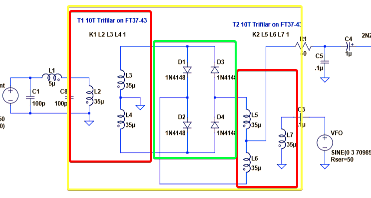
It shows a sine input to L7 in the mixer but apparently a square wave can work?
violet parcel
didnt know you were looking for it
official version for their normal 5W transceiver: https://www.qrp-labs.com/images/qcx/HiRes4a.png
 late fulcrum
It also shows ordinary 1N4148 diodes, which wouldn't be my first choice
violet parcel
and for the digital one: https://qrp-labs.com/images/qdx/schem4.png

the digital one is less interesting because it isnt doable with a breadboard. Where the normal one uses an atmega328p so by definition it can be done on an arduino
late fulcrum
That seems like a peculiar design in a lot of ways. It's doable on a breadboard, but would be complicated
violet parcel
but for the life of me I cant find the si synthethizer on the schematics
late fulcrum
In the digital one, it's just to the right of the and gate below the blank space in the center
In the analog one it's near the center, below the heavy bus line
Drawn as a rectangular box with 10 connections
violet parcel
late fulcrum
It seems like an odd choice for a transceiver as all those harmonics would requi...
so these schematics that was all to answer this question of yours... after I asked what about the Si5351 adafruit sells vs the ad9850 ?
besides the wait they seeems like a bettee option to learn for me than starting from scracth
late fulcrum
I suppose the digital output is workable if you're doing postprocessing of the signal to iron out all the harmonics. But if you want to use the signal more directly, it's easier to start with a sine wave output.
violet parcel
and the local chapter likes when ham operators buy radio that are easy to maintain/repair with a clear schematic/bom in the manual
late fulcrum
One nice thing about my ancient Kenwood is it's easy to work on. Well documented, not crowded, not a lot of special parts
violet parcel
can you actually upgrade such things yourself wiith say a less noisy power supply, better caps/resistors etc ?
late fulcrum
For a long time, it was just expected that ham gear came with full service documentation, but that trend seems to be dwindling as radios become just chips on boards
violet parcel
is that why you keep it because you could mod it ?
late fulcrum
Yeah, I'm going to mod mine to make the VFO more stable, for example
violet parcel
it seems the only thing left that have a full service documentation are RF avionics like ATC receiver
most open manuals I ever found some even give specs for the pcbs and alternatives for the ICs
late fulcrum
And many oscilloscopes, as they're expensive instruments aimed at people who repair stuff
A lot of military and test gear in general comes with good docs
violet parcel
yeah... hehehe ... Always surprised me it's super easy how to operate the combat computer in an american self-propelled artillery directly from the us army online but I cant find a service manual for my toaster
late fulcrum
You're totally right about avionics too
 violet parcel
receiving atc is something that would interest me as well as an rf project since it seems legal in canada
late fulcrum
I built an ATC receiver from a kit a while back, it works pretty well. And yes, it's legal to listen in.
violet parcel
but my SDR cant really do it, getting too much noise even if I use a metal broom + a metal trash can + the sdr V antenna as an antenna
Like I gave it as much surface as I could and the db gots better from -60 to -40 but still no good 😦
But Im behind the ATC and I think the building absorb most of it
late fulcrum
I'm not sure what the SDR V antenna is, but most of the SDR antennæ I've seen are not optimized for frequencies that low
Also, some SDRs have built-in filters to block common high power signals
violet parcel
ah it's the RTL-SDR Blog V3 R860 RTL2832U RTLSDR kit
it says it has some sort of parameters for ranges in the low mhz/high khz
but it's possible the antenna cant actually do it
late fulcrum
One nice thing about well documented avionics is the information is available to figure out how to operate them with an Arduino
violet parcel
havent used it for a while because all I catch is FM radios and the neaby local chapter repeater near 240mhz
yeah it's surprised all you can operate with an arduino provided you have a bench power supply
like old floppy disk drives work perfectly with an arduino as long as you have a 14V@60W power supply for the molex cable or berg cable
but after that it is magnetic reads and motors, super easy for an arduino
late fulcrum
I run mine with an old Coleco power supply

 violet parcel
late fulcrum
I run mine with an old Coleco power supply
violet parcel
late fulcrum
I run mine with an old Coleco power supply
If you cant tell I still struggle a lot with converting voltage/power
it's not a project that interest me anyway. Threw the ones I had in the recycling box a long time ago
canada is kinda chaotic for ham thought
wish we had an ARRL. I had to asks someone to talk on their repeated to be able to reach my local chapter...
couldnt reach them by phone/email/social media. And everyone seems to sell their own license training
which is kinda annoying because you have to say no to two of the three between the local offer, the province chapter and the national chapter
welll.. I guess it will have to wait I just chipped a tooth and that will probably cost 200-300$....
rapid geode
mmm ham
so i just put in a request for a raise of 5.... degrees celcius.
brrrrrrrrrrrrr
 primal junco
hi
night crescent
Desk of Ladyada - Some New Designs in a New Year https://youtu.be/YYXufxPQAPU

Fresh designs: a 12V to 5V DC buck converter for QT Py, a CAN Bus BFF, and a fixed UPDI programmer. A key focus is a board for 'true analog' LED strips to simplify wiring, converting NeoPixel signals to a single 'big LED'. Plus, a compact three-channel logic inverter is sourced for this project.
violet parcel
ok Im confused. Might just be a faulty cap because they are like 4 years old
But I dont understand why putting a cap (100uF) before the led make it much more dim (barely visible) when the resistor is at the safety limit for the led (330 ohm) (9V battery)
Like it gets dimmer and dimmer I was expecting the opposite
late fulcrum
I would expect it to glow briefly and dim as the cap is charged, then go out, unless the cap is placed backwards, in which case the reverse leakage would light the LED
violet parcel
oh yeah I have to put it in parallel probably not series...
late fulcrum
Yeah, then it would brighten as the capacitor charges
violet parcel
shrug maybe Im using the wrong type of capacitor or something
late fulcrum
Or it's backwards...
violet parcel
I tried both sides, led light up but immediately turns off
Trying to find fritzing on my computer to show circuit
I was testing my capactors and leds before I do the astable multivibrator from a 9v battery... Only have 100 uF caps thought
late fulcrum
That's a peculiar way to "test" capacitors
violet parcel
multimeter sways 96.5uF to 97.1uF
violet parcel
late fulcrum
That's a peculiar way to "test" capacitors
I wasnt testing the capacitors, I want to have a blue and right led and I have a led kit so Im testing with capacitors how long the fade is vs the brightness and if I like what I see
because if I use a lower ohm value the fade is much shorter and so on. I guess I should use a potentiometer...
It's more like does it look bright enough / does it looks good
with 2k ohm it looks perfect for the red light
This is to avoid having to use a different resistor value for each led in astable multivibrator
late fulcrum
Trying to do both at once that way means the resistor is setting both the capacitor charging current and the maximum brightness. If you do use a pot, make sure to have a series resistor as well so the maximum current can't get high enough to damage the LED if you turn it too far.
violet parcel
yeah I always do start, whatever I do I see the minimum resistor value as part of the led then I do my circuit. Im on 9V currently but apparently my battery has antimatter in it or something and is at 9.9V... So I use the weskest possible led voltage range (1.8V-2.4V) and 20mA. It says 405ohm, I do admit sometimes I dont bother and just use a 330 ohm honestly and I just tap the ground wire to the battery to do my test so it's open for like 100ms. But in this case I think 1000 ohm will eb perfect for both
Im not sure what the heck is going on with that 9v battery especially since it wasnt used for 4 years
I have a blue component with legs but I cant read what is on it and I have no idea what it is
late fulcrum
The most common blue components I see are metal film resistors (generally with color band codes), electrolytic capacitors (cylindrical, with a shrink-wrap plastic cover over the can), and safety-rated capacitors (generally disc format).
330 ohm is pretty low, I'd use 470 ohm
And yeah, 1000 ohm is even better (and a common value)
violet parcel
Seems like I only have 4 capacitors all across my kits, all are 100uF. Thinking of getting about 60 (4xdifferent values x 15) wurth elecktronics capacitors all aluminum electrolytes and maybe a 8$ 400F supercap to expertiment.
what do you think ?
polyester ones seems to have ripple current in the several amps... and MCUs are rated for liek 400mA...
Ideally Id pick ones rated at up to 50V, almost 0 ESR and almost 0 ripple current (or at leats in the single digit mA) but it seems that doesnt exists
Also -40oC to 115oC 50V -40oC is to keep options open for the future
late fulcrum
For large values, electrolytics are generally the practical choice. For small values, film and ceramic are popular. Ripple current is rarely a problem with small value capacitors, there's nothing special about polyester ones in that respect, they're just a kind of film capacitor (they're popular for low distortion audio circuits). For medium value capacitors, MLCC and electrolytic are popular, and it's generally in the medium and large value applications that ripple current becomes an issue.
violet parcel
Like if I ever do a weather station, and 115oC usually means twice the lifetime when you use them for every slice of -10oC under
late fulcrum
I think you misunderstand what ripple current means...
violet parcel
yah I guess I should have mnentionned I have around 12 ceramic caps
but I like capacity in general for caps so Im good for decoupling ceramic caps I think.
late fulcrum
I generally buy 125°C 10000 hour or better capacitors when getting electrolytics. Sometimes the polymer electrolytics are a good choice, but you'll run into size/cost/lifetime/ESR tradeoffs in general with electrolytics.
violet parcel
yeah even with normal electrolytes they can get from 0.30$ to 0.75$. Buying 10 reduce that price by 30% so I will get x10 for 2-3 common values
I also looked at like rubycon/nihicon/tdk/panasonic but these companies were involved in the taiwan capacitor scandal in the 2000s so I personally dont really trust them
late fulcrum
"almost 0 ripple current" is not what you want
violet parcel
I dont understand ripple current that is true, I looked at 3 threads on reddit but they focused on audio and power supply
late fulcrum
Those companies were not the guilty parties! It was those companies whose designs got copied, but not copied correctly, and the bad copies had very poor lifetimes.
"Ripple current" is how much AC current a capacitor can withstand. It tends to be a big factor in switching power supplies which operate at high frequency with large amounts of AC current flowing around. For ordinary 60Hz supplies, it's generally not significant.
So the amount of DC current an MCU draws has little to do with ripple current requirements
violet parcel
I also dont understand the tolerances scales honestly either. Like some are +/- 20% seems like the most common ones. But digikeys also have most of them at -10/+50% or -10/+70%.
The ones I have are from "chongx" but the C is partially erased so Im not sure and they all seems with a tolerance of less than 4% on the multimeter they seems pretty good...
late fulcrum
Electrolytics are intrinsically low-tolerance devices. They're just used to provide bulk capacitance.
I don't worry about tolerance with electrolytics, as "enough" is sufficient. So if I calculate I need a minimum of 302.3235µF, I'll just use 470µF or 1000µF and call it a day. There's a reason electrolytic capacitors are often stocked in E3, E2, or even E1 series.
violet parcel
oh yeah I dont really mind about getting more F than expected either 😄
last thing I dont understand is the low frequency/high frequency ripple is that related to audio / ham application or just the AC frequency ? Because Im not aware AC goes from like 80 Hz to 120 kilohertz
My multimeter might be having issues too since sometimes when I check the capacitors after I use them the capacitor read like 10 million ohms on a resistance test. But I wait 10-20 second should be sufficient to discharge and they read 0.4V. Im a bit confused byt this
I guess the tests charge them up or something...
violet parcel
gearing up for the astable multivibrator: . Still have to do a sketch in fritzing to figure out how to connect and which side the transistor goes on

 zealous void
Happy Monday! I'm a semi-noob looking for some confirmation on what I am planning to buy from adafruit for my project. (Hopefully this is the right place) I have 4 water buckets with plants growing in them. I would like to monitor the temperature and water level, so I can fill them up as needed from a 5th bucket. I already have a Shelly RGBW2 programmed and working well with 4 water valve solenoids, and a S31 turning on and off the pump. (ESPHome/Home Assistant controlled) I think I only need the water level sensors now so I can go monitor and go on vacation some day. 🙂
So far my picks are:
- 5 Adafruit VL53L4CX ToF sensors since it has a narrow FOV and amazing range (I plan to place these on top of a 3d printed 3 inch diameter tube to give me ~9 inches of travel. I might need to put a foam floaty in it if it can't read the water.)
- 5 ADS1115 16-Bit ADC - 4 Channel with Programmable Gain Amplifiers
- 5 High Temp Waterproof DS18B20 Digital temperature sensor (I see now this is digital and the ADS1115 is Analog, woops)
- 1 Adafruit LTC4311 I2C Extender / Active Terminator (for longer range)
- 8 RJ-45 Ethernet Female Socket to Terminal Spring Block Adapter
- 1 Adafruit TCA9548A 1-to-8 I2C Multiplexer Breakout (i2c address fix?)
I haven't used something like the i2c mutiplexer and extender before, but from what I can understand it's difficult to change the address on the ToF sensors since it needs to be done every boot. Also I think I will need the extender as the buckets are all about 5+ ft away from where the controller will be.
Anything recommendation before I give Adafruit another paycheck? 😄
 violet parcel
I have only 1 but Im far from being an expert. I feel like for outside use paying extra for a 16 bit ADC/DAC isn't really worth it unless it's shielded well
Seems to me like you will lose precision from the environment since it's meauring in the milivolt range and it's outside next to other milivolts phenomenas. Or maybe you already took care of the shielding and didnt mention it
zealous void
violet parcel
I have only 1 but Im far from being an expert. I feel like for outside use payin...
Awesome, thank you for the tip. Yeah, I feel like I am doing something wrong there. Not sure the best way to get Water temp sensor information into i2c.
zealous void
violet parcel
Seems to me like you will lose precision from the environment since it's meaurin...
Nope, I know nothing about minivolt phenomenas, thank you for bringing that up. I will try to find a better solution. Thank you!
violet parcel
let me check for the i2c adress thing. If it is soldered it would seem youd be toast
but if it's not the multiplexer wouldnt seems necessary
is it the #381 DS18B20 or the #642 or #374 you plan to get 5 of ?
My intuition since you can set the adress on register 50h in ROM from the datasheet and the library: https://www.arduino.cc/reference/en/libraries/ds18b20/ is that at first glance you wouldnt need the multiplexer
The Arduino programming language Reference, organized into Functions, Variable and Constant, and Structure keywords.
besides it would surprise me you can choose by soldering since neither of the 3 products seems to give physical access to the chip
late fulcrum
violet parcel
gearing up for the astable multivibrator: . Still have to do a sketch in fritzin...
Typically there are two active components (such as transistors) in an astable multivibrator
zealous void
violet parcel
is it the #381 DS18B20 or the #642 or #374 you plan to get 5 of ?
Let me figure that out, I'm not sure of the difference at this time.
violet parcel
The code in the library uses 1-wire SEARCH_ROM so it seems it would support you selecting the adress in the ROM in a 1st program setting them up individually, then using 1-wire search_rom in your favorite language
late fulcrum
The DS18B20 is a "1 wire" device, not an I2C one, so it doesn't need a multiplexor.
zealous void
I was thinking I needed the multiplexer for the ToF sensor, I didn't think about the DS18B20. I was having trouble finding if it workes directly with i2c, or if I needed another sensor to send it on the bus.
violet parcel
late fulcrum
Typically there are two active components (such as transistors) in an astable mu...
there are two transistors in the pic, I mean like I dont yet which leg is - and which is + vs the lettering on it since the legs are the same length
zealous void
late fulcrum
The DS18B20 is a "1 wire" device, not an I2C one, so it doesn't need a multiplex...
Ok, I had a feeling, that goes directly into an input on the controller. Do you know of a better way to get water temp into the i2c bus, or am I thinking about this incorrectly? (I normally do)
patent hemlock
zealous void
Nope, I know nothing about minivolt phenomenas, thank you for bringing that up. ...
you might just try a zigbee water sensor since you have HA in the mix
late fulcrum
zealous void
Ok, I had a feeling, that goes directly into an input on the controller. Do you...
The 1-wire bus will need its own GPIO (and pull-up resistor), the I2C bus will need 2 other GPIOs
zealous void
patent hemlock
you might just try a zigbee water sensor since you have HA in the mix
I agree with you, that might be what I end up doing. I would "prefer" to have 1 controller sending it all back to HA if possible.
violet parcel
yeah seems like the ToF sensor is fixed at 0x52 I2C adress
late fulcrum
And you're right, the VL53L4CX doesn't have a choice of I2C addresses, so if you want to use more than one of them, you'd need a multiplexor (or multiple I2C buses)
zealous void
violet parcel
yeah seems like the ToF sensor is fixed at 0x52 I2C adress
They said it CAN be changed via software, but it doesn't sound fun, and isn't permanant.
violet parcel
Newbie question if I may Tweak. What does the ToF sensor does here ?
Because I have a similar problem except Ill use one to avoid plant rather than determine their height
late fulcrum
violet parcel
there are two transistors in the pic, I mean like I dont yet which leg is - and ...
Transistors don't have + and - pins, they have base, emitter, and collector (for bipolar transistors) or gate, source, and drain (for MOSFETs). The data sheet will show the pin order (the package has a flat face for orientation)
zealous void
The ToF sensor will be in a tube going down into the water bins, measuring the level of water in the bins. I need the tube as the roots of all the plants would make the readings unreliable.
late fulcrum
Basically an electronic sight glass
zealous void
Hopefully, that's the plan. If it doesn't read the water level well, I plan to put a small foam float in the tube. It should read that well. The narrow field of view should give me about 9 inches of range if I aim it decent.
violet parcel
hmmm I thought the analog super cheap sensor as long as a ruler would be sufficient here. Am I missing something ? Like is there a difference between the tof sensor and planting a water level copper ruler in the soil with that supercheap analog sensor ?
ie:
 late fulcrum
That doesn't read water level, it reads soil conductance
zealous void
I have had zero luck with those. Their quality seems extremely bad, I am an idiot, or both. Also there won't be any soil, just water, and there is air injected in the water to oxygenate the water. The micro splashes should most likely make that inaccurate.
violet parcel
maybe madbodger can comment about the ADC 16 bits if there are still analog devices here. But I feel like you will get lot of microvolts level stuff from the ground/air here and youd need great isolation/shielding to take advantage of the 16 bits
zealous void
Good idea however, I tried it before in my automatic dog watering bowl. 🙂 Works for a bit, a very short bit.
patent hemlock
you could always use a float and micro-switch arrangement, kind of like an old-style toilet float
violet parcel
Since your setup seems to be on stone I assume you will pass wires under the stones so if the wires arent shielded for that you'll get microvolts level from the earth
Not to mention anything happening ijn the air (ie: same type of stuff as RF noise for ham where weather affects it all the time)
patent hemlock
put a ball in a tube with a micro-switch at the "feed me" level and when the float drops below the required level, the switch turns off and you have a simple binary signal
zealous void
patent hemlock
you could always use a float and micro-switch arrangement, kind of like an old-s...
Yes, I agree, that would work. That would sacrifice adjustability and detail in logging. I agree, it would most likely work fine (if no roots got caught in it), but I would also like to log detailed trends in water consumption. For example, if it changes when the lights are off for 6 hours. When humidity is higher/lower.
patent hemlock
zealous void
Yes, I agree, that would work. That would sacrifice adjustability and detail in...
yeah, i think the ToF and float will give you more accurate level measurements
zealous void
violet parcel
Since your setup seems to be on stone I assume you will pass wires under the sto...
This is in a grow tent inside my house.
violet parcel
I guess I'll use something else than the above water level for detecting if my bath is about to flood then 😦
patent hemlock
just line the "measuring tube" with something non-reflective so your ToF sensor only "sees" the float
violet parcel
possibly an edgjr float
patent hemlock
oh, duh -- use a float on an arm and attach it to a rotary sensor
zealous void
patent hemlock
oh, duh -- use a float on an arm and attach it to a rotary sensor
Good idea, but sadly the roots in the water would easily stop the float.
patent hemlock
no, the float needs to sit on top of the water/fluid next to the roots
zealous void
I actually tried it with a float valve that let water in manually when the water was low, but the roots ended up holding the float down and over flooding the water bin. :/
zealous void
patent hemlock
no, the float needs to sit on top of the water/fluid _next to_ the roots
Interesting, do you have an example of this? I would like to see.
The roots go everywhere btw, like ... everywhere. 🙂
violet parcel
wouldnt a sealed tube with a very small hole to hold the float works here ?
with the sealed tube peventing the roots from getting in (so like semi-thick safety glass or hard plastic)
patent hemlock
so let me see if i can sketch something out
zealous void
(Not my picture/video) Example:
 zealous void
violet parcel
wouldnt a sealed tube with a very small hole to hold the float works here ?
zealous void
violet parcel
wouldnt a sealed tube with a very small hole to hold the float works here ?
I'm not sure what you are explaining there. Sorry.
Is there a reason we don't like the ToF sensor?
violet parcel
Like you plant a tube in the pot like its a plant. with an hole it should have the same water level as the rest of the pot
the tube has an opening on the top
late fulcrum
ToF sensor seems fine to me. It's possibly overkill, but that's no big deal if it works.
I might go with a simple ultrasonic distance sensor, but either should do.
zealous void
Alright. Was just wondering if I missed something where it wouldn't work. I often overkill, I have issues. 🙂
late fulcrum
Believe me, I know what that's like
violet parcel
Im not sure about my plan so Ill just stop mentionning it but I was basically saying to plant something like this in the pot, but empty - without a plant and the sensor goes in it instead. if there is a hole at the bottom it would fill up with water and works like a sight:
 zealous void
So, now I just need to figure out the order for the Mutiplexor and the Extender/terminator.
patent hemlock
 late fulcrum
Like I didn't need to use a micropipette to dispense precisely 13µl of optically clear epoxy in each opening to glue in the LEDs here. I could have just globbed ordinary cheap 5 minute epoxy in with a toothpick. But that's not how I roll.
 violet parcel
I think me and edgjr saying pretty much the same thing lol
zealous void
violet parcel
Im not sure about my plan so Ill just stop mentionning it but I was basically sa...
I'm having trouble understanding what that is a picture of.
violet parcel
zealous void
I'm having trouble understanding what that is a picture of.
do you know what a test planter tube is ?
zealous void
I do not.
patent hemlock
there's a float in a tube that you insert into your tubs, the float moves a mechanical arm/linkage that pivots on a rotary sensor, which gives you "clicks" -- this allows you to make all sorts of adjustments


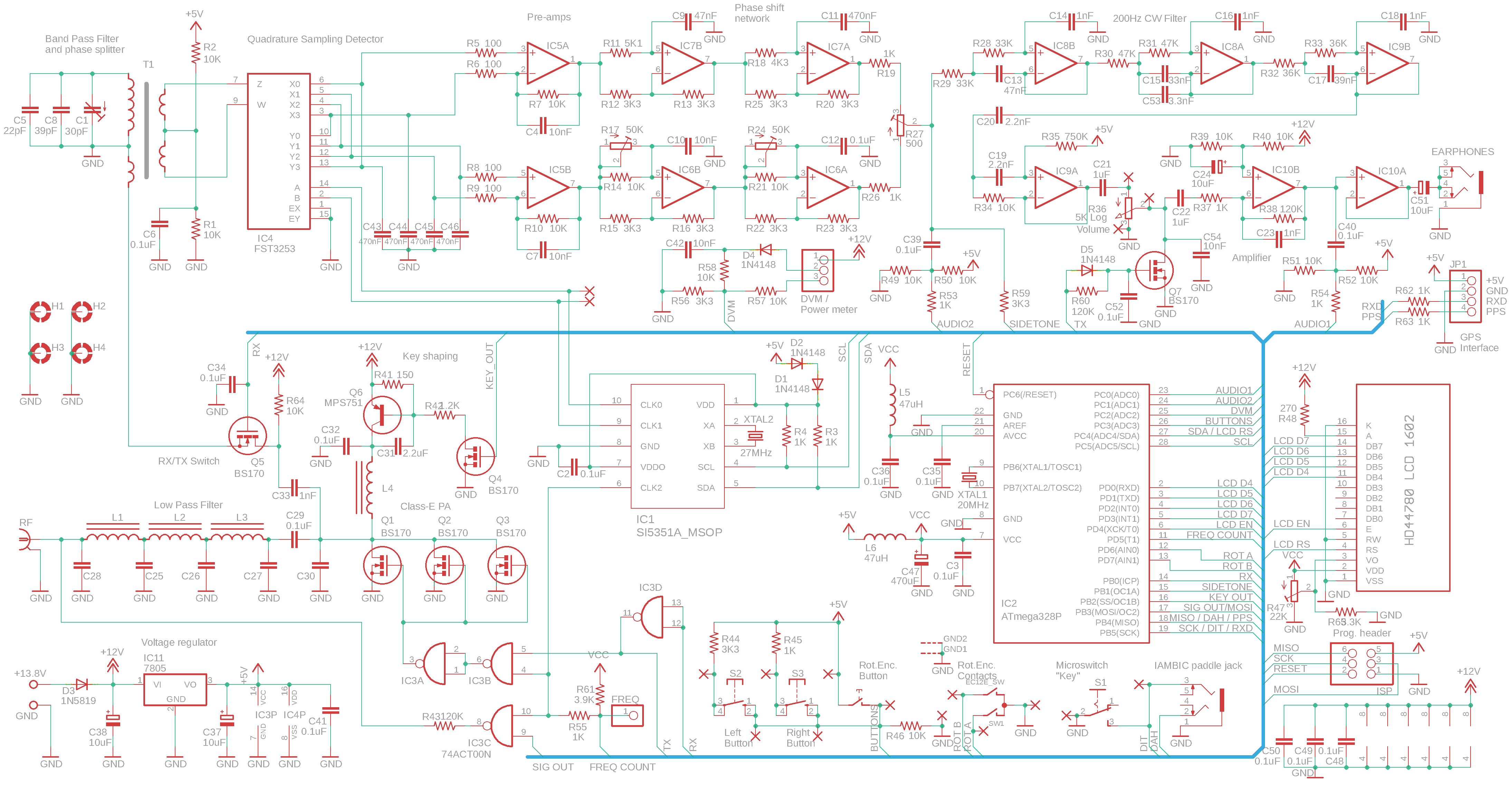
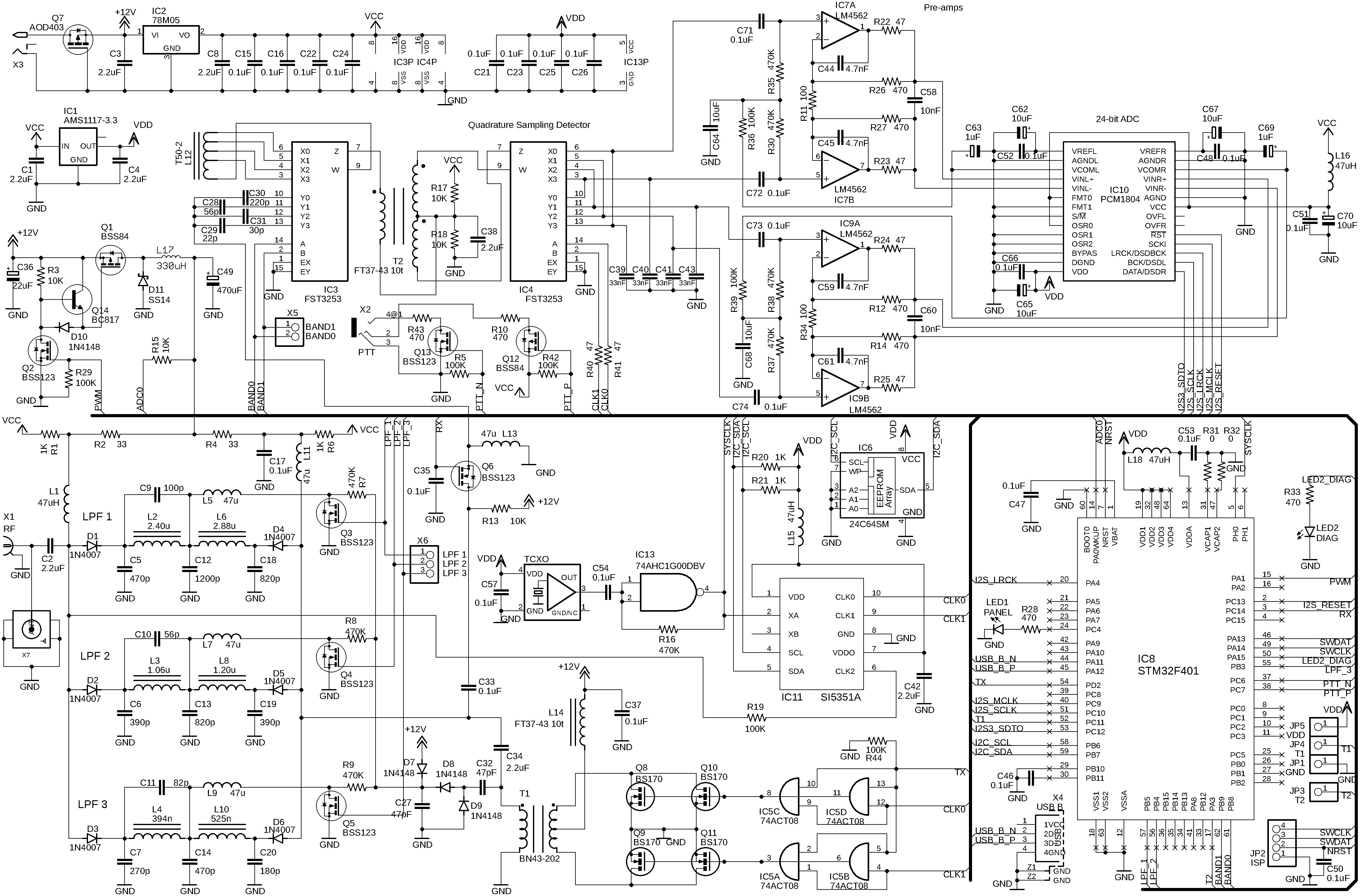 late fulcrum
It is possible your float could get hung up in the roots too
violet parcel
Complete picture, but the point isnt the plant. It's a test tube / test planter tube

and you could put a float in it instead of a plant
zealous void
late fulcrum
It is possible your float could get hung up in the roots too
Agreed, I was hoping that the ToF sensor can pick up water level without the float. I'm not sure however.
violet parcel
and plant it