#help-with-radio
1 messages · Page 18 of 1
 young cove
 static snow
They have the old 1n34a germanium diodes, too. https://www.jameco.com/z/1N34A-Major-Brands-Diode-1N34A-General-Purpose-Germanium_2220533.html
Order Today Major Brands Diode 1N34A General Purpose Germanium. Authorized Distributor - Products in stock ready to ship.
young cove
I had one of these as a kid

attached the alligator clip to the phone dial stop and could hear Atlanta 200 miles away
static snow
Same here. Used my allowance to buy it from a 99-cent store during a family cross-country road trip. The alligator clip found dozens of antennas and non-antennas.
Had a galena cats whisker unit at home with a coil wrapped around an oatmeal container.
young cove
we are old
static snow
young cove
we are old
Incredible depth of experience.
 buoyant spindle
i found my dads old 200 in 1 electronic lab and built a crystal radio, among other things. its why i am interested in tech
 umbral oxide
ugh, Helium Miners are apparently one of the causes of LoRaWAN gear being scarce
 lilac arrow
umbral oxide
ugh, Helium Miners are apparently one of the causes of LoRaWAN gear being scarce
lilac arrow
umbral oxide
ugh, Helium Miners are apparently one of the causes of LoRaWAN gear being scarce
Hadn't heard of that. Offhand, it looks like a great way to (a) lose money (b) get infected.
umbral oxide
and waste energy
lilac arrow
I treat the word "blockchain" as a red flag.
lilac arrow
umbral oxide
and waste energy
"Mining HNT with Hotspots is done via radio technology, not expensive or wasteful GPUs." -- so it must be ok 🙂
 granite spear
It's actually an interesting concept. They go by "proof of connectivity"... you earn coins by providing routing services to devices within the range of your hotspot.
 quiet eagle
Hello all. I want to develop on a chip with BLE 5.2 using arduino. The nrf52832 says its BLE 5.3 on nordics website but I think the chip being used on the feather boards is 4.2. Any insights would be greatly appreciated.
granite spear
quiet eagle
Hello all. I want to develop on a chip with BLE 5.2 using arduino. The nrf52832 ...
I think the BLE version is dependent on the Nordic SoftDevice firmware version loaded on the chip. The 52832 was originally released with 4.2 but they've been able to keep up with later Bluetooth revisions with just software-stack upgrades, so the latest supports 5.3, I think.
quiet eagle
I see. Has the arduino library been upgraded to support latest SoftDevice firmware?
granite spear
That I don't know, I'm afraid, though I'd assume things have been kept relatively up to date, since it's a popular platform.
young cove
quiet eagle
Hello all. I want to develop on a chip with BLE 5.2 using arduino. The nrf52832 ...
The adafruit BSP for nRF52 on Arduino uses SoftDevice 6.1.1, which I think is Bluetooth 5.0. It has support for extended advertising. I'm not sure what version https://github.com/sandeepmistry/arduino-nRF5 supports.
 orchid portal
hey there friends, I'm looking for a NFC breakout board where the antenna is detached or that is small enough to fit in a 6cm x 6cm box. Does anyone have any suggestion?
 primal warren
orchid portal
hey there friends, I'm looking for a NFC breakout board where the antenna is det...
primal warren
orchid portal
hey there friends, I'm looking for a NFC breakout board where the antenna is det...
Here's one possibility https://github.com/Parsav/PN532ExtAntNFCBreakout
GitHub
Arduino compatible PN532 breakout board with support for external antenna. - GitHub - Parsav/PN532ExtAntNFCBreakout: Arduino compatible PN532 breakout board with support for external antenna.
This one doesn't give a size (other than "small"), but I suppose you could extrapolate the board size from the connector pin pitch http://www.hiletgo.com/ProductDetail/2156958.html
PN532 NFC NXP RFID Module V3 Kit Near Field Communication Reader Module Kit for Android Phone,Modules/Sensors
orchid portal
thanks I will take a look
primal warren
Here's another one that looks particularly compact https://www.seeedstudio.com/Grove-NFC.html

Built around PN532 module Contactless communication at 13.56MHz. Support ISO14443 Type A and Type B protocols Support I2C or UART communication protocols Grove connector compatible
orchid portal
yeah I just got that one tks
 eager isle
IDK if this should be #help-with-wippersnapper-and-adafruitio, sry if that's the case;
I've got a FONA 3G (https://www.adafruit.com/product/2691), and I'm unable to get anything done with it; Via raspberry i get static green and red LED, and via windows 10 I'm unable to install the drivers (Both missing signature and non compatible)
I'd like to continue work with the raspberry, but while following the guide I can't do anything, I got as far as the https://www.adafruit.com/product/2691, where testing with screen I see nothing while writing the command, and receive no response
Serial console option in raspi-config is set to: SSH OFF, Serial ON
primal warren
eager isle
I'd like to continue work with the raspberry, but while following the guide I ca...
How are you hooking it to the Pi? Asynchronous serial?
eager isle
Followed the guide on adafruit; TX and RX to the raspi pins, 3V to VIO, GND to GND

Adafruit Learning System
Connect your Linux board to the internet through a cellular data connection with FONA!
primal warren
I think it should answer serial commands if the speed is correct and the console is disabled
eager isle
Is it possible that i'm using the wrong serial interface on the OS? (ttyAMA0)
That photo has what looks like an original Raspberry Pi, while i've got a Pi Zero W2
 pearl tendon
Hi,
I want to receive the data from two Lora transmitters at one Arduino at the same time (and want to send data to one of the transmitters from the receiver-Arduino). Would I need two Lora Modules at the receiver Arduino for that? I don't want to loose bit rate. Answers are very appreciated!
If my explanation was unclear, I tried to visualise it

the dashed lines are the lora signals
 normal drift
Just to start the conversation, I'm not convinced two receivers will help. If the transmitters are sending at the same time, I think they will interfere and you will have to deal with that anyway.
What kind of data rates are you expecting? How often are the transmitters sending data and how large are the packets?
 shell lava
Also, unless you use something like FreeRTOS (which supports threading), I’m pretty sure the Arduino platform is single-threaded so how would you read from both data streams at the same time? It seems like having the transmitter devices buffer/store their data and then having the receiver interrogate them periodically for new data would avoid a LOT of technical complexity to me.
(I don’t know anything about LoRA, so there may be nuance here I’m not aware of, but that’s my initial off-the-cuff thought.)
normal drift
Something like the "reliable datagram" mode in the RadioHead library can help with occasional collisions but then you have to restransmit the packets, impacting your data rate.
pearl tendon
mmh s transmitter 1 should constantly send data to the receiver and the receiver should constantly send data to the transmitter 2. Transmitter 2 just sends data every few seconds
normal drift
"constantly" is troublesome. Can you be more specific. How big is the packet and how often is it sent?
It won't transmit and receive at the same time.
What library are you using for the code? IS this with the Arduino IDE or CircuitPyhton?
pearl tendon
normal drift
It won't transmit and receive at the same time.
oh that's good to know
pearl tendon
normal drift
What library are you using for the code? IS this with the Arduino IDE or Circuit...
Arduino IDE
normal drift
Which Library?
normal drift
There is some discussion here for Arduino-Lora https://github.com/sandeepmistry/arduino-LoRa/issues/13 -- You may also want to look into the Radio Head Libraray
How much data are you really sending?
Also, what hardware are you using? the typical sx127x tranceivers are "half-duplex" the can only transmit or receive. Page 23 https://cdn-shop.adafruit.com/product-files/3179/sx1276_77_78_79.pdf
pearl tendon
Well the transmitter 1 sends little compressed images, the transmitter 2 sends strings (not long) and the receiver sends numbers
pearl tendon
normal drift
Also, what hardware are you using? the typical sx127x tranceivers are "half-dupl...
I am using an sc1278
normal drift
And how fast do they have to send them?
normal drift
Well, I still think a second receiver will not help much. Just my opinion.
normal drift
One issue you will have is that both receivers will receive all the data, they then have to decide if the packet was for them or not.
You are very welcome -- It sounds like a great project. good luck and keep asking questions. I hope others will comment.
pearl tendon
normal drift
You are very welcome -- It sounds like a great project. good luck and keep askin...
Thanks a lot
pearl tendon
normal drift
One issue you will have is that both receivers will receive all the data, they t...
I think there is this sync word function which should prevent this
normal drift
I'll need to do some reading to comment on that but it still has to "receive" the signal to check the sync word.
 cunning rapids
Will the 8 Channel LoRa Gateway HAT with LoRa and GPS Antenna - SX1301(without the pi) work with the Adafruit LoRa Radio FeatherWing - RFM95W 900 MHz?
cunning rapids
I should ask.. Are they able to communicate with each other since they are both 915 MHz?
granite spear
cunning rapids
I should ask.. Are they able to communicate with each other since they are both ...
Yes, the radios should be compatible. I'm not sure what you mean by "without the Pi", though... the Hat board won't operate by itself.
cunning rapids
meaning the 8 chanel lora gateway hat that doesn't include the pi. I wasn't sure if there was a difference between the kit that includes the pi.
granite spear
It's just whether you already have a Pi to use or not.
cunning rapids
I figured. Thanks
normal drift
I just stumbled across this library for the RFM9x on a Raspberry Pi https://github.com/epeters13/pyLoraRFM9x So far it is working well for some simple tests. I was curious if anyone had had any experience with it. I was also able to exchange packets with a Pi using the CircuitPython RFM9x library.
cunning rapids
I'm attempting to make sense of lora technology. Can three Adafruit Feather M0 with RFM95 LoRa Radio - 900MHz communicate with each other? Or can only 2 communicate at a time? My goal is to have one RFM95 as a base station and two other RFM95 as sensor nodes. All three RFM95 should beadle to communicate back end forth
normal drift
cunning rapids
I'm attempting to make sense of lora technology. Can three Adafruit Feather M0 ...
Multiple rfm9x radios can communicate. They will all see each others traffic, but the software can sort out which unit should accept the packet. Are you using Arduino or CircuitPython? If Arduino, what library?
For the Arduino Radiohead library or in CircuitPython, there is a "packet header" that contains optional addressing information. If the packet is not addressed to a particular receiver, it ignores the packet.
It should be fine to have 2 sensor nodes and one base.
cunning rapids
It doesnt matter if I use arduino or circuitpython.
normal drift
The feather M0 RFM9x is has very limited RAM and space for code when using CircuitPython. It depends on how many sensors and driver libraries you need. Arduino works well.
The Radiohead library also has a mode called "reliable datagram" in which each packet has to be acknowledged. If not, the packet is resent. This may be very useful with multiple radios so you don't have issues with packet collisions.
cunning rapids
Arduino it is than. The M0s will be handling only lora. They M0s will connect to rp2040s via UART. The 2040s will handle the sensor data than send over a JSON steing to the M0s to send out
That is what I was thinking of doing.
I dont have the M0 radios yet but will be here any day, so i'm in the brain storming stage of my project.
normal drift
What kind of data rates do you need?
cunning rapids
I dont exactly know. Each sensor has the ability to calculate the values within a second. Once the data is calculated they can be sent off. But I think sending data every 2 to 3 seconds might be too much and may cause issues
normal drift
Yes, that can be an issue. If you can live with 5 to 10 seconds it’ll be a lot easier. Also depends on the range you need.
normal drift
Sounds like a great project.
cunning rapids
Thank you for your help :-)
umbral oxide
Devices with radios often have instructions not to power the device unless an antenna is connected or it may get damaged. What's the mechanism for damage, as opposed to just a weak signal?
normal drift
https://en.wikipedia.org/wiki/Dummy_load. The reflected power causes the damage
umbral oxide
ah, thanks @normal drift, more the transmit than the receive, that makes sense
normal drift
Yes, I don’t think receive matters. Just no signal.
 tiny plaza
Hello! I want to set up two of the 900 MHz RFM95 shielded LoRa modules in a way where one is transmitting and one is receiving and it isn't a two way link since I want to use it in a scenario where being able to accomplish stable 2 way transmission is far from a guarantee, one side doesn't need to transmit, and I would like to run multiple simultaneous receivers. What's the best way to make that happen?
I was able to set them up to talk to each other but the link is only stable if the receiving module sends a packet back after it receives one.
I'm pretty new to RF
normal drift
tiny plaza
Hello! I want to set up two of the 900 MHz RFM95 shielded LoRa modules in a way ...
What software are you using (Arduino - what library or CircuitPython)? Also what hardware are you using? Is this the Feather M0 rfm9x or some other MCU with an add on RFM9x board?
granite spear
tiny plaza
I was able to set them up to talk to each other but the link is only stable if t...
The base LoRa protocol doesn't have any concept of a "link" or use acknowledgements, it just has the sort of bare sending and receiving packets treatment that you want. So it sounds like you may be using some sort of higher-level library which is adding on reliable-link features you don't need.
tiny plaza
normal drift
What software are you using (Arduino - what library or CircuitPython)? Also what...
I was using a Teensy 3.5 and 3.6 connected to the RFM95 running the RadioHead library and the example code from the Adafruit GitHub
tiny plaza
granite spear
The base LoRa protocol doesn't have any concept of a "link" or use acknowledgeme...
Interesting, if so I’m guessing that’s the case. When I comment out the RX part of the transmit part of the example code, it stops doing sends
normal drift
Are you using the reliable datagram mode? That automatically sends ack packets in response to a received message.
normal drift
tiny plaza
Interesting, if so I’m guessing that’s the case. When I comment out the RX part ...
I’m not sure I understand. Can you post your code?
Also examples only send a message in response to a packet.
tiny plaza
I was using https://github.com/adafruit/RadioHead/blob/master/examples/feather/Feather9x_RX/Feather9x_RX.ino and https://github.com/adafruit/RadioHead/tree/master/examples/feather/Feather9x_TX

GitHub
A github'ified version of http://www.airspayce.com/mikem/arduino/RadioHead/ - RadioHead/Feather9x_RX.ino at master · adafruit/RadioHead
GitHub
A github'ified version of http://www.airspayce.com/mikem/arduino/RadioHead/ - RadioHead/examples/feather/Feather9x_TX at master · adafruit/RadioHead
I commented out the part in the send code that waits/listens for a response but that just causes it to only send one packet and then stop
granite spear
Can you pastebin your modified code? Probably it's just not fully commented out.
tiny plaza
Pastebin
Pastebin.com is the number one paste tool since 2002. Pastebin is a website where you can store text online for a set period of time.
granite spear
You might want to put the delay(1000) back in, since right now it's sending packets as fast as it can. Where in the loop does it stop?
tiny plaza
granite spear
You might want to put the `delay(1000)` back in, since right now it's sending pa...
I'll try that
Yeah re-adding the delay didn't fix it
granite spear
Where exactly is it stopping, based on the print statements?
tiny plaza
It goes through the entire loop twice and stops at rf95.waitPacketSent();
I removed that line and re-ran the code and it goes through the entire loop 3 times and stops in that scenario

 granite spear
Hmmm, that's puzzling. I'm not sure what's going on there, since there should in general nothing to block a send from completing.
tiny plaza
That's why I'm so confused lol
That's why I thought there must be some kinda of LoRa mechanism that requires two way transmission or something kinda like TCP but I'm pretty sure there should be an option to not do that
normal drift
Is there a second board running that is receiving the packets and responding to it?
tiny plaza
Yes
Same setup, just using the receiver code
I had to change the LED pin to a different random one since it's shared with the SCK pin and I also commented out the serial wait loop but other than that it's the same as the example
Also It's a t3.5 instead of a 3.6 but that shouldn't have any impact in this scenario
normal drift
Can you turn off the receiver board and try just the transmit. -- also post the reciever board code.
tiny plaza
Pastebin
Pastebin.com is the number one paste tool since 2002. Pastebin is a website where you can store text online for a set period of time.
In that case it doesn't even finish the first loop
 normal drift
char radiopacket[20] = "Hello World # "; change this to char radiopacket[20] = "Hello World # ";
tiny plaza
That fixed a typo but otherwise had no impact
 normal drift
I was concerned that you were putting too many characters into the buffer. You have to leave a byte for the string "null terminator"
tiny plaza
That makes sense
It was working perfectly fine as long as I use the full two way code, I just can't get it to only work one way
Commenting out the recieve part or turning off the reciever is what breaks it
normal drift
That is odd -- try commenting out the waitPacketSent line and put in a delay(1000)
tiny plaza
 normal drift
Also , Is the interrupt pin connected?
tiny plaza
I'm pretty sure it is, I'll double check the wiring
Yep, the G0 pin is connected to pin 4 of the Teensy
I'm pretty sure the SPI pins are right or it wouldn't even be possible to connect
Reset is connected to pin 9 which matches the code
I'll run the send on the receiver just to see if that works
Ok so it works from the reciever board for some reason but not from the send board
I'm guessing my wiring is wrong
normal drift
I just loaded you code (the pastes bin )into my feather m0 rfm9x board and it runs continuously
I think it is hanging for you-- waiting for an interrupt...
G0 should be on Pin 7 according to your code\
nevermind -- I misread your code -- Pin 4 is correct
tiny plaza
I'll run a continuity test to see if maybe one of the breadboards I'm using just particularly sucks
normal drift
Good luck, but Its good to know it works on one board!!
tiny plaza
Yeah I think it's a hardware gremlin somewhere I'll have to sort out lol
Thanks for all the help!
normal drift
Once you get things sorted out, you may want to consider upgdaing the the latest version of the RadioHead library v 1.121 http://www.airspayce.com/mikem/arduino/RadioHead/
tiny plaza
I've been letting PlatformIO handle versions of things, I'll check to see if it's up to date sometime today
normal drift
Oh -- OK -- you may have it --I thought you got it from the Adafruit guide page.
tiny plaza
I mean I copied the code from the guide page lol but I use PlatformIO for everything I do. Thanks for the tip though!
normal drift
The guide link is to an older fork
tiny plaza
I'll keep that in mind
normal drift
Good luck with your project!
tiny plaza
Thank you!
 simple anchor
I have a long-running FeatherS2 circuitpython program that connects to WiFi and then does a time.sleep() for a minute, queries the internet, then repeats that cycle indefinitely. I want to check the internet connection before I do the query because it failed for some reason after a few hours in testing and it's just the right thing to do anyway. I'm looking at either doing a ping(4.4.4.4) or doing an ap_info() call. I think the former is the better idea. With ping() I have to wait, but if ap_info() is suitable maybe I don't have to wait? Any suggestions? https://circuitpython.readthedocs.io/en/latest/shared-bindings/wifi/index.html#wifi.Radio
I'm just noticing this about re-connections. I guess I need to do more testing.

I'm thinking now a ping() with a reasonable timeout, look for None which would represent no active connection. Strictly speaking this isn't perfect but this is not a mission-critical app anyway. Still open to advice, thanks.
umbral oxide
@simple anchor curious why the sleep between connection and query? If you want to know if you are connected to wifi (it is possible to get disconnected and have the automatic retries run out), check for wifi.radio.ipv4_address. If you have an wifi.radio.ipv4_address, you are connected to wifi. ping is a reasonable check for WAN connection (though not 100% reliable), but you could also just try the query, and take some other actions if it fails... do some retries, wait and retry, handle any exceptions, etc.
(wifi.radio.ap_info. calls won't tell you if the WAN is up)
there can also be dns issues, WAN server issues, even routing issues, so the best way to know if you can hit a server is to hit the server
simple anchor
I mis-spoke. I connect, I query, I sleep, rinse and repeat
thanks will try your suggestions, this helps
 thick pike
I have a MagTag, and I'm trying to post some data to a web server using adafruit_requests. Unfortunately, I run into an odd error if the data is more than 2925 characters (I'd like to send a JSON payload of about 20k).
import wifi
import socketpool
import adafruit_requests

from config import config  # I store my passwords here instead of secrets.py

wifi.radio.connect(config["ssid_home"], config["wifi_password_home"])

pool = socketpool.SocketPool(wifi.radio)
requests = adafruit_requests.Session(pool)
response = requests.post(config['logging url (raw)'], data='a'*2925)  # works
response = requests.post(config['logging url (raw)'], data='a'*2926)  # fails

# Traceback (most recent call last):
#   File "<stdin>", line 1, in <module>
#   File "adafruit_requests.py", line 756, in post
#   File "adafruit_requests.py", line 717, in request
# OutOfRetries: Repeated socket failures
On my web server I see I returned an HTTP status of 400. Any idea what's going on?
I'm able to send the same (or much larger) payload to the same server URL w/ Postman, so it doesn't seem like the issue is on the server side.
umbral oxide
@thick pike is the url http or https? what versions of CircuitPython and Requests? I can replicate this, but at a slightly lower data size. It's getting [Errno 11] EAGAIN.
thick pike
@umbral oxide it's http, just to a Pi on my local Wifi (http://192.168.4.226:5000/postraw). Everything's pretty up to date, with the MagTag running CircuitPython 7.1.1 and adafruit_requests is 1.10.5.
umbral oxide
I tried with a larger timeout and it still doesn't work. Not sure at this point what would introduce a limit.
doesn't work on esp32-s3 either, leading me to think it's not a memory issue
thick pike
Not a lot of Google hits for '[Errno 11] EAGAIN' unfortunately...
umbral oxide
it needs to be a dict though
but that doesn't make a difference in this case, even a large dict errors
thick pike
What, the data argument? It works for me without being a dict. The json argument needs to be a dict, but I switched to just trying to send the raw data for now as an experiment for debugging this issue.
umbral oxide
yeah, I didn't read far enough into the requests code
there does seem to be a bug, if I try to send 3000 bytes, here's the output:DEBUG b'POST' DEBUG b' /' DEBUG b'post' DEBUG b' HTTP/1.1\r\n' DEBUG b'Host: ' DEBUG b'httpbin.org' DEBUG b'\r\n' DEBUG b'User-Agent: Adafruit CircuitPython\r\n' DEBUG b'Content-Length: 3000\r\n' DEBUG b'\r\n' DEBUG b'aa ...3000 of them...aa' DEBUG b'aaaaaaaaaaaaaaaaaaaaaaaaaaaaaaaaaaaaaaaaaaaaaaaaaaaaaaaaaaaaaaaaaaaaaaaaaaaaaaaaaaaaaaaaaaaaaaaaaaaaaaaaaaaaaaaaaaaaaaaa' [Errno 11] EAGAINit sends an extra 120... doesn't match the content-length header, not sure if tht's why the failure
Do you want to file on issue on the Requests library?
thick pike
Yeah I can file it. Can you post your code that just generated that output?
 grand breach
tiny plaza
Thank you!
grand breach
tiny plaza
Thank you!
I have Circuitpython programs for the RFM95 (70 cm version)...one that transmits only...and one that receives only. They use the Adafruit rfm9x libraries. They just send and receive exemplary data that I use for radio propagation testing. You wanna see them?
@tiny plaza Here is the transmitter program:
:
Here is the receiver:
Be sure to change the frequency used. I use 426.1 mhz since I am a license ham.
 urban iris
hello! I am using a feather m0 lora board and my project is a radiosonde, if I want to transmit from min 3km with direct visibility what antenna can I use for 433MHz frequency?
grand breach
urban iris
hello! I am using a feather m0 lora board and my project is a radiosonde, if I w...
Where are you located?
if you want to buy a high quality antenna for 433 mhz, Try a Smiley 5/8 Slim Duck:

Smiley Antenna Company, Inc.
or maybe one of these incredible, super slim antennas from SignalStuff:

Now offering quantity discounts! See below for discount table. Please select the frequencies and color that you want below -- the "classic" signal stick is "Dual Band" and "Black". PLEASE check the connector against the pictures before ordering -- many people mix up connector types and genders! NOTE: Some radios have an abnormally long SMA po...
granite spear
Although a whip antenna might not have the best emission pattern for an air-to-ground link, since it's mostly going to have the highest gain horizontally.
urban iris
If I will use a yagi uda antenna with big gain for RX on the ground and a whip antenna in the air, it might work?
young cove
urban iris
If I will use a yagi uda antenna with big gain for RX on the ground and a whip a...
that would be a great idea
a user did some range testing with the LoRa boards; I am trying to find it
also maybe of interest: https://forums.adafruit.com/viewtopic.php?f=57&t=181349
Some of these are at 900MHz instead of 433
starting with a simple straight-piece-of-wire antenna will be simplest, but it sounds like you cannot control the polarization of the remote antenna - its orientation will change. You may want to use a circularly polarized higher gain antenna on the ground station.
normal drift
urban iris
If I will use a yagi uda antenna with big gain for RX on the ground and a whip a...
You may have to be careful that you have the yagi pointed at the radiosonde. That is will you be able to track in in flight and keep it pointed?

 restive fjord
w00t
urban iris
i have simulated this antenna for 433MHz and obtain a 5db gain, I thing might works

 nova nebula
Does anyone know if there is a way to modify a RFM69CW from 433Mhz to 915Mhz? Hopefully it could be removal of a few parts on the board.
young cove
nova nebula
Does anyone know if there is a way to modify a RFM69CW from 433Mhz to 915Mhz? Ho...
The base chip is the same, but the RF components vary.You'd have to substitute new capacitors, etc. If you didn't, you'd get poor signal strength on both reception and transmission. Much easier to buy a new module.
nova nebula
Gotcha, thanks @young cove for filling me in. I figured it was probably some sort of RC filter that would need to be adjust, but I was hoping it would be a simple pop off a capacitor somewhere. Are there any schematics of the values used, or is that something locked down by hoperf?
I'm going to buy the different type boards, but I'm just interested in seeing what might be the things that are different between the two.
young cove
nova nebula
Gotcha, thanks <@329766224093249548> for filling me in. I figured it was probabl...
I looked in the HopeRF datasheet, but I did not see a detailed schematic with values.
It would be both L & C components, probably
 pastel granite
Is there some way I could substring a BLE device address, as returned from the Address object of an Advertisement?
I ask because I can get the proper address without issue, but it's formatting is overly long for my purposes.
Example:
for advertisement in ble.start_scan(ProvideServicesAdvertisement, timeout=10):
 (...)
 connection = ble.connect(advertisement)
 device_address = advertisement.address
The last line will make device_address an Address object with a string value of <Address: xx:xx:xx:xx:xx:xx>
However, I want to substring this so I only get the actual address, not the leading <Address or trailing >. It doesn't seem to be possible to substring the value directly, since device_address = advertisement.address creates a copy by reference not value.
umbral oxide
can you use str() or repr() on the object and trim down the resulting string with .replace() or similar string function
pastel granite
str() doesn't work. Let me try repr(). Thanks, Anec 🙂
repr works - thanks again 😄
young cove
pastel granite
`repr` works - thanks again 😄
The Address object only prints with the prefix. You can use .address_bytes to get the raw bytes of the address.
pastel granite
young cove
The Address object only prints with the prefix. You can use `.address_bytes` to ...
That actually gave me what looked like corrupted output - it skipped a hex value in the address.
young cove
pastel granite
That actually gave me what looked like corrupted output - it skipped a hex value...
It will print as a b’…’ bytestring. Not all the bytes will show up as hex. If any can be represented as printing characters, they will not show as \xnn, but as that character.
pastel granite
young cove
It will print as a `b’…’` bytestring. Not all the bytes will show up as hex. If ...
I understand, but at one point I was getting "xx\xx\\xx\xx\xx" - it literally didn't print one of the valid hex values
granite spear
pastel granite
I understand, but at one point I was getting "xx\xx\\\xx\xx\xx" - it literally d...
If you still have that output saved, paste it and people can probably help figure out why it was encoded that way.
young cove
pastel granite
I understand, but at one point I was getting "xx\xx\\\xx\xx\xx" - it literally d...
Definitely interested in fixing any bad behavior here, if you have the example.
pastel granite
I'll see what I can do to reproduce this when I have a moment.
pastel granite
Is there a way to explicitly end a BLE connection? For some reason my central isn't notifying the connected device that the conversation is over.
young cove
pastel granite
Is there a way to explicitly end a BLE connection? For some reason my `central` ...
connection.disconnect() 🙂
pastel granite
young cove
`connection.disconnect()` 🙂
I've tried this, but querying connection.connected immediately afterword returns True - doesn't that indicate the connection is still alive?
young cove
pastel granite
I've tried this, but querying `connection.connected` immediately afterword retur...
.connected might reflect the true state of the connection, or it might be broken 🙂 . If you wait a bit, does it eventually show as disconnected?
pastel granite
Unfortunately no. I've put a wait timer on it, and the state doesn't change.
Is there a way for the client to end the connection?
pastel granite
young cove
`.connected` might reflect the true state of the connection, or it might be brok...
Ok, I've moved some code around and connection.disconnect() now seems to behave properly. Going to assume it was my error there. I'm still very curious why the connection stayed alive, but don't have time to really drill down. Thanks @young cove .
young cove
maybe you reconnected right away by accident; anyway, glad it's fixed
pastel granite
Thanks again. I'm still confused about why BLE connections take so long to connect upon finding an advertisement. When/if you have a moment can you let me know what might be going wrong?
# Start BLE communications
try:
 while True:
  self.logger.info("= Looking for advertisements")
  for advertisement in self.ble.start_scan(ProvideServicesAdvertisement, timeout=5):

   if BLE_Service not in advertisement.services:
    continue
   else:
    self.logger.info("= Found BLE advertisement")
    self.ble.stop_scan()
    sensor_connection = self.ble.connect(advertisement)
    self.logger.debug("= BLE connection established")
     break

   # If have an active connection
   if sensor_connection and sensor_connection.connected:
    self.logger.debug(" = Fetching Connection")
    BLE_Service_Instance = sensor_connection[BLE_Service]
It's the last line of this section of code that takes a long time to complete. This has made it necessary to insert some confirm before continuing heuristics that really muck-up the code.
Thoughts?
young cove
pastel granite
Thanks again. I'm still confused about why BLE connections take so long to conne...
Besides self.logger.debug(" = Fetching Connection"), is there logging after BLE_Service_Instance = sensor_connection[BLE_Service] that indicates that particular line is taking a long time? Or are you doing self.ble.connect() but sensor_connection.connected is not True?
pastel granite
young cove
Besides ` self.logger.debug(" = Fetching Connection")`, is there logging afte...
The code that proceeds afterword transmits data from the remote that has been stored in an array.
young cove
if it's not true you will go around the for loop again, and there will be another 5 second timeout
pastel granite
young cove
if it's not true you will go around the `for` loop again, and there will be anot...
pretty sure I'm still connected, because disconnecting was an issue
I am logging things to console after this code - will the slow things down?
young cove
right, but you are waiting for another advertisement? Could you upload the whole program and the logging output?
The logging time should not be significant.
pastel granite
I don't think I can send the whole codebase - is that what you're asking?
What I notice is that there's a significant pause once I get to self.logger.debug(" = Fetching Connection")
i.e. it prints the debug statement and waits for at least 1 second (probably closer to 3) before continuing
this is consistent
young cove
pastel granite
I don't think I can send the whole codebase - is that what you're asking?
I just want to see what's above and below the excerpt
pastel granite
Will take me a second to format, but thanks 🙂
 slender current
Is your connection bonded? CircuitPython might be reconnecting on its own
young cove
slender current
Is your connection bonded? CircuitPython might be reconnecting on its own
rick.james had to send me private code; the length of time to do discovery was surprising to him, but he's all set now
 fervent cloak
Hey everyone, I was just playing with a couple Feather M0 with RFM95 LoRa Radios - 900MHz
Using only slightly modified rfm9x_transmit.py examples to send from one to the other.
Everything is working fine, I can even "see" it with RTL-SDR
(Great tutorials and examples - thank you)
Anyway, I picked up a random bytearray using 915MHz and it can be successfully decoded with .hex() in Python
Hex length = 86
Just curious if anyone had any ideas what other devices might be sharing 915?
And maybe any ideas for filtering/ignoring?
Thanks for any suggestions.
granite spear
Those frequencies are used in LoRaWAN networks, I would expect, so you could be picking up that traffic. The packet structure would probably have some clues with the address header or something. Though you may want to think about including some sort of signature or checksum in your own packets to distinguish them from everyone else's.
umbral oxide
I get about a packet an hour on 868 and 915 on rfm9x from some distance away (-100 dB or so), varying packet lengths
fervent cloak
Thanks for the reply @granite spear
I was a bit hesitant to share the bytearray/hex data in case it contains personal info etc. After trying to decode in multiple character encodings I'm stumped.
I live in a fairly rural resort town in Canada. If that helps 😄
Here is the Received (raw bytes): bytearray(b'\x82\xc2\xe7i\x81T\x1c\x15-\xa5\x88\xee\xd1\x99J\x8dHY.}\x88\xb6K\xef\xd1f$x\x05\t\xc8\x8fu\xcd\xef\x023\x91{\xc7T\x01\xe2')
To hex .hex()
'82c2e76981541c152da588eed1994a8d48592e7d88b64befd16624780509c88f75cdef0233917bc75401e2'
Just a mystery - not a support case FYI
Thanks to all
umbral oxide
I can't make heads or tails of the packets I see, no consistency in content or structure, so I assume it's all encrypted. My LoRaWAN gateway rarely sees anything, so I'm guessing the packets are just LoRa.
normal drift
I pick up lots of “noise” packets on my rfm9x boards. I usually use addressing to filter them out.
I've tried to figure out where they are coming from, but have not found anything that makes sense.
normal drift
fervent cloak
Hey everyone, I was just playing with a couple Feather M0 with RFM95 LoRa Radios...
I meant to tag you on my replies above -- If you are using the CircuitPython or Arduino RadioHead libraries, you can set addresses for each board as part of the packet header. This has worked well for me. It looks like you are using the CircuitPython library. Take a look at the rfm9x_node1.py and rfm9x_node2.py examples https://github.com/adafruit/Adafruit_CircuitPython_RFM9x/tree/main/examples
 magic verge
Maybe we need a "radio direction finding" app.
umbral oxide
normal drift
I've tried to figure out where they are coming from, but have not found anything...
maybe just another hobbyist wondering where your packets are coming from
 worn laurel
I'm successfully driving a single chain of 120 neopixels (5x24 pixel rings) from a qt-py-esp32-s2 under circuitpython 7, using a variant of wheel().
That is, until I turn on the wifi. At that point the neopixels regularly blink white for very short periods of time. It occurs in all five of the wheels, although the blip seems to last longer or perhaps is just brighter at the far end of neopixel chain.
I'm pretty sure it's not voltage drop due to undercurrent because the processor continues to run just fine. I assume it's either the wifi radiation interfering with the PWM signal directly, or maybe the ESP32 has some internal clock instability that is exacerbated in this configuration. I haven't had trouble driving a single 24 pixel wheel.
Does anyone have any troubleshooting suggestions?
granite spear
worn laurel
I'm successfully driving a single chain of 120 neopixels (5x24 pixel rings) from...
Are you using a 3.3V-to-5V level shifter? It might be that the PWM signal was a little marginal to start with and some extra noise from the WiFi is pushing it over the edge.
worn laurel
Aw heck I'm not even using a level shifter! The PWM signal worked so well from a 3.3v pin (under non-wifi conditions) that I completely forgot about it. Thank you for that suggestion.
 plain bluff
I was range testing two LoRA 433 rfm96W modules tonight one with dipole antenna and the other with a yogi. The range was very short close to 200 ft. How do I increase power and range?
Slow down the baudrate to 1MHz and set power to 23?
granite spear
LoRa has a number of knobs to turn related to baud rate, like the "spreading factor" and error-correction options, so you've got a lot of potential tradeoffs between speed and distance.
plain bluff
What would you recommend?
normal drift
plain bluff
I was range testing two LoRA 433 rfm96W modules tonight one with dipole antenna...
200ft is very low for range. I would suggest you first check the wiring/functionality of to your antennae carefully. Just using simple 1/4 wave wires you should get much better range than that.
plain bluff
I was using a dipole antenna to transmit and yogi to receive
normal drift
plain bluff
I was using a dipole antenna to transmit and yogi to receive
My point was that if you are only getting 200 ft range, I think you have a problem with your antenna or connection to it. I would suggest solving that before adjusted the power or modem configurations. You could try just using a 1/4 wave piece of wire as described here https://learn.adafruit.com/adafruit-rfm69hcw-and-rfm96-rfm95-rfm98-lora-packet-padio-breakouts/assembly#wire-antenna-2433240-7 just to see if it works better than your dipole or yagi.
plain bluff
Yeah I double checked the wiring and believe it is good now. Moved to 5V
normal drift
Moved what to 5V?
 severe furnace
I'm not sure if this is the particularly proper area to ask about what I am having problems with, but I am currently using an adafruit feather M0 with RF95 LoRa. I am using this in tandem with a sparkfun zed-f9p (GPS module) connected over RX/TX. The short of it the sparkfun is sending rtcm correction data over the RX/TX lines to the LoRa, and I am trying to then transmit that straight over the RF95 to another module to pick it up and use it. If any of this sounds wrong please correct me because I am a little new, but I am reading in the data from RX/TX over Serial using Serial.read()/Serial.readBytes() to read in my data which usually goes fine. But the second I try to send the data I have just read from there over the radio, my next reads may contain incorrect/corrupted data and for the life of me I have not been able to find out why it is doing that. Without sending over radio, it reads fine, but the moment it is turned on the read in data starts getting messed up. To note: this is essentially a loop of read in correction data through Serial over RX/TX, place it in a buffer, use that buffer with the RF95 Radio head library to then send that data over, then start the loop again
normal drift
severe furnace
I'm not sure if this is the particularly proper area to ask about what I am havi...
It would be best if you can upload your code so people can look it over and offer suggestions. Use the + at the left to attach the file.
severe furnace
Just to add context and RTCM message has a preamble byte D3, followed by two bytes denoting the length of the data, a field with length pertaining to what was previously said, and 3 parity bytes at the end
normal drift
severe furnace
Just to add context and RTCM message has a preamble byte D3, followed by two byt...
It looks like your messages are > 256 bytes, If I am not mistaken, there is a 256 byte limit for LoRa packets (including the RadioHead Header) You may need to break the message into two packets.
severe furnace
normal drift
It looks like your messages are > 256 bytes, If I am not mistaken, there is a 25...
I just checked in the rH_r95 library and I don't know how i missed that, I suppose I need to look at that in the morning, thanks
normal drift
severe furnace
I just checked in the rH_r95 library and I don't know how i missed that, I suppo...
https://www.airspayce.com/mikem/arduino/RadioHead/classRH__RF95.html see the section on packet format - looks like 251 bytes of data
Good luck
plain bluff
normal drift
Moved what to 5V?
I moved the power pin from 3.3 to 5V
normal drift
plain bluff
I moved the power pin from 3.3 to 5V
What microcontroller are you using? The rfm9x boards only need 3.3v unless you are using 5V MCU i would not expect any difference.
They should be powered by the same voltage as the MCU
plain bluff
Just curious, why is that
normal drift
The rfm9x will drive the gpio signals to match the input voltage. So you want to match the input voltage to what the MCU expects on its GPiO signals.
The breakout has a voltage regulator so the rfm9x module will only see 3.3v but it level shifts the gpio lines to match the input voltage.
pastel granite
Noob question: When getting a list of services from a connected BLE device, the UUIDs are backwards, in 2-character chunks. Any way I can easily reverse that, or read it out nicely in the first place?
Right now I'm manually reversing it - feel like I'm missing something.
magic verge
Sounds like you need to change the endian-ness when you unpack the UUID.
severe furnace
normal drift
Good luck
Sadly that does not seem to be the issue, yes it may be in the future, but currently all the messages coming in are of size 250 or less
normal drift
severe furnace
Sadly that does not seem to be the issue, yes it may be in the future, but curre...
Bummer... It seemed to simple... The only other thing I can think of is if the data is being treated as an ASCII string, do you have a null terminator (zero byte) as the last byte of the packet...Could it just be that the receiving end is not seeing the string terminator... just a guess.
severe furnace
normal drift
Bummer... It seemed to simple... The only other thing I can think of is if the d...
Which packet are you referring to? Because the packet is being treated just as an array of bytes, as it should be, there shouldn't be a null terminator anywhere because it isnt a string
Wait let me check into that actually...
normal drift
severe furnace
Which packet are you referring to? Because the packet is being treated just as ...
Can you provide an example of the issue -- It's not completely clear to me where the problem is occurring. Is it the data in this that gets corrupted Serial.printf("Message: \n"); for (int i = 0; i < msgLength && msgLength > 0; i++) { Serial.printf("%02x ",(char)receivedChars[i]);
severe furnace
A message would normally be something like
Message: D3 00 04 4C E0 00 80 Ed ED D6
But occasionally we may get something like
D3 ff 00 04 4C E0 00 80 ED ED ...
When without using the radio reading over the rx/tx through serial1 the normal message will come through
normal drift
Ugh -- That sounds like something completely different than I was imagining. I though you had bad data at the end.. Since it is embedded in the string it is really puzzling....
severe furnace
It's as if reading over the serial bus gets fumbled
normal drift
It's strange since you are not even transmitting while you are reading so its not like the radio is corrupting the serial line. Or is the message arriving while you are transmitting?
Just guessing now, but are the wires for the serial line near the transmitting antenna -- can you try moving or shielding them.
I have to go offline for awhile -- it does sound like some sort of interference to me. I wish I had better ideas!
severe furnace
correct me if I'm wrong Serial if it's receiving data it pushes it into a buffer would you can then check it has items by doing Serial.available() to check how many bytes are in it, and then when you call some sort of Serial.read() it takes from first of the buffer and returns that. With what I'm doing it is highly likely that the buffer does receive items while a transmission is going on.
lilac arrow
severe furnace
I don't see how it would cause the behavior you're seeing, but it looks like the if-expression inside the loop should use == not =, and the copy to receivedChars[0] in the line right before it should instead be inside the loop.
severe furnace
lilac arrow
I don't see how it would cause the behavior you're seeing, but it looks like the...
Yeah I fixed that equal issue earlier today already I noticed that. What do you mean the copy to receive char 0 should be in the loop are you talking about within that if statement?
lilac arrow
sorry, yeah, I meant in the if-block.
severe furnace
I mean I could, but if I don't find that preamble byte I just loop again until I find one and replace it constantly
lilac arrow
It looks to me like if you ever receive anything other than 0xD3 at the start of the loop, you'd reach the rf95.send call with that character at the start of the buffer and msgLength whatever it was previously.
normal drift
@severe furnace The other thing I am wondering is, how large is the HWSERIAL1 FIFO? Is it possible that when you are transmitting, you are taking too long to service the HWSERIAL1 and data is being lost. Nice catch on the "=="
severe furnace
normal drift
<@!112293787438493696> The other thing I am wondering is, how large is the HWSE...
After some Google searching since I don't have the board in hand I've seen 256 bytes which is pushing right up on that limit of the message size of a single message
So if the device sends more than one message quickly, right now I have it sending the minimum recommended of 6, and it takes too long to transmit those messages/ parse them as they come in, the buffer starts to overflow.
So that could explain why when I'm not sending them, I'm reading quick enough, but when i try to send it the transmitting takes just a little too long and the messages arrive quick enough to fill the buffer
severe furnace
After an adequate amount of testing, it was the receive buffer overflowing
normal drift
severe furnace
After an adequate amount of testing, it was the receive buffer overflowing
Good to know. Good luck finding a workaround.
severe furnace
normal drift
Good to know. Good luck finding a workaround.
I already have found a couple it's also because the rf95 module was taking upwards of 40-225ms to send a message, you can change the receive buffer size(not that good), empty the read in buffer and essentially create my own serial buffer but on my side and not effecting their predefined driver code and send messages over the rf95 as little as possible
 novel hinge
Hello. I am using the nRF52840 with Lora Wing RFM95 to send data to TTN and it is working fine.
However, I would like to receive also data from TTN to process on the feather. Is this feasible ? are there any available examples or documentations that would help me to do this ?
normal drift
novel hinge
However, I would like to receive also data from TTN to process on the feather. I...
Good question! I have never tried it, but there appears to be some mechanism for sending "downlink" messages. At least that seems to be the terminology used by TTN. I suggest doing some searching for receiving TTN downlink messages at a node. Good luck!
novel hinge
Hi Jerry. Thank you for your suggestion !
I just noticed that in the arduino lmic library the feature of receiving downlink packets is implemented but apparently I was unable to find any examples for this online (so far at least).
Will read the library carefully and try to implement and test this.
normal drift
I'll be interested to know how it works.
novel hinge
Sure . I will let you know or post it here if I was able to come up with something that works !
 fast isle
cant remember - searching for , 2.4Ghz 4 button transmiiter and receiver chip pair - cant remember the company -- they use them in cheap rc cars
 crimson wing
Whats the cheapest board to get an FM signal through I2S or headphones? Im looking to use something with CircuitPython for testing an FM transmitter.
It doesnt have to "seek" radio stations or anything, I can specify the frequency
young cove
crimson wing
Whats the cheapest board to get an FM signal through I2S or headphones? Im looki...
we don't sell some kind of FM receiver module (we do have a low-power transmitter)
what do you want to do that a regular FM radio would not do?
primal warren
crimson wing
Whats the cheapest board to get an FM signal through I2S or headphones? Im looki...
Clock radio at a thrift store, $1.
primal warren
This is the radio channel, this question may be more appropriate in the makecode channel
 turbid sapphire
Hi y'all! I'm running an ItsyBitsy RNF board (running with a Clue (running Central). I found two examples, one of which I believe works (the peripheral), but the Central is giving me some grief.
The code is as such:
# SPDX-License-Identifier: MIT

"""
Demonstration of a Bluefruit BLE Central for Circuit Playground Bluefruit. Connects to the first BLE
UART peripheral it finds. Sends Bluefruit ColorPackets, read from three accelerometer axis, to the
peripheral.
"""

import time

import board
import busio```Ok... what ever that was...
Anyway, I'm getting the following error:
Scanning...
found a UARTService advertisement
Traceback (most recent call last):
File "code.py", line 56, in <module>
NameError: name 'accelerometer' is not defined
I'm using this on the Clue
This is the example code in CircuitPython 7.x
Since the ItsyBitsy doesn't have an accelerometer, I'm assuming that's why I get the error. But how do I get rid of that and replace it with the sensor that's on there - currently, an MLX90640
And actually, there aren't any references to an accelerometer in the Peripheral code... 🤔
turbid sapphire
This is the code for the MLX:
    stamp = time.monotonic()
    try:
        mlx.getFrame(frame)
    except ValueError:
        # these happen, no biggie - retry
        continue
    print("Read 2 frames in %0.2f s" % (time.monotonic() - stamp))
    for h in range(24):
        for w in range(32):
            t = frame[h * 32 + w]
            if PRINT_TEMPERATURES:
                print("%0.1f, " % t, end="")
            if PRINT_ASCIIART:
                c = "&"
                # pylint: disable=multiple-statements
                if t < 20:
                    c = " "
                elif t < 23:
                    c = "."
                elif t < 25:
                    c = "-"
                elif t < 27:
                    c = "*"
                elif t < 29:
                    c = "+"
                elif t < 31:
                    c = "x"
                elif t < 33:
                    c = "%"
                elif t < 35:
                    c = "#"
                elif t < 37:
                    c = "X"
                # pylint: enable=multiple-statements
                print(c, end="")
        print()
print()```I don't need the ASXIIART and I can delete those lines with no issues.
turbid sapphire
I modified the peripheral to the following:
# SPDX-License-Identifier: MIT

import time
import board
import busio
import adafruit_mlx90640

# Only the packet classes that are imported will be known to Packet.
from adafruit_bluefruit_connect.packet import Packet
from adafruit_bluefruit_connect.color_packet import ColorPacket

from adafruit_ble import BLERadio
from adafruit_ble.advertising.standard import ProvideServicesAdvertisement
from adafruit_ble.services.nordic import UARTService

PRINT_TEMPERATURES = True

i2c = busio.I2C(board.SCL, board.SDA, frequency=800000)

mlx = adafruit_mlx90640.MLX90640(i2c)
print("MLX addr detected on I2C")
print([hex(i) for i in mlx.serial_number])

mlx.refresh_rate = adafruit_mlx90640.RefreshRate.REFRESH_2_HZ
ble = BLERadio()
uart = UARTService()
advertisement = ProvideServicesAdvertisement(uart)

frame = [0] * 768
while True:
    stamp = time.monotonic()
    ble.start_advertising(advertisement)

    while not ble.connected:
        pass
    while ble.connected:
        packet = Packet.from_stream(uart)
        if isinstance(packet):
            print("Read 2 frames in %0.2f s" % (time.monotonic() - stamp))
    for h in range(24):
        for w in range(32):
            t = frame[h * 32 + w]
            if PRINT_TEMPERATURES:
                print("%0.1f, " % t, end="")
        print()
    print()
    try:
        mlx.getFrame(frame)
    except ValueError:
        # these happen, no biggie - retry
        continue ```

All it states is that it detects the I2C channel but says or does nothing else.
The Clue is just "scanning".Another rendition...
# SPDX-License-Identifier: MIT

import time
import board
import busio
import adafruit_mlx90640

# Only the packet classes that are imported will be known to Packet.
from adafruit_bluefruit_connect.packet import Packet
from adafruit_bluefruit_connect.color_packet import ColorPacket

from adafruit_ble import BLERadio
from adafruit_ble.advertising.standard import ProvideServicesAdvertisement
from adafruit_ble.services.nordic import UARTService

PRINT_TEMPERATURES = True

i2c = busio.I2C(board.SCL, board.SDA, frequency=800000)

mlx = adafruit_mlx90640.MLX90640(i2c)
print("MLX addr detected on I2C")
print([hex(i) for i in mlx.serial_number])

mlx.refresh_rate = adafruit_mlx90640.RefreshRate.REFRESH_2_HZ
ble = BLERadio()
uart = UARTService()
advertisement = ProvideServicesAdvertisement(uart)

frame = [0] * 768

while True:
    stamp = time.monotonic()
    ble.start_advertising(advertisement)
    while not ble.connected:
        pass
    while ble.connected:
        packet = Packet.from_stream(uart)
        if isinstance(packet):
            print("Read 2 frames in %0.2f s" % (time.monotonic() - stamp))
    for h in range(24):
        for w in range(32):
            t = frame[h * 32 + w]
            if PRINT_TEMPERATURES:
                print("%0.1f, " % t, end="")
                uart.write("%0.1f, " % t, end="" % (mlx))
        print()
    print()

    try:
        mlx.getFrame(frame)
    except ValueError:
        # these happen, no biggie - retry
        continue ```

I just get this:
code.py output:
MLX addr detected on I2C
['0x925', '0xb6e9', '0x189']I'm confused, it looks like the for h in range and the try-except should be inside the while ble.connected loop. Also you are printing frame values before you read them
turbid sapphire
I'll give that a look tomorrow. I appreciate you helping me!
turbid sapphire
This is what happens with brute force coding .. 😀
turbid sapphire
Ok... I think I got the sending - at least it's printing in the Serial Monitor:
# SPDX-License-Identifier: MIT

import time
import board
import busio
import adafruit_mlx90640

# Only the packet classes that are imported will be known to Packet.
from adafruit_bluefruit_connect.packet import Packet
from adafruit_bluefruit_connect.color_packet import ColorPacket

from adafruit_ble import BLERadio
from adafruit_ble.advertising.standard import ProvideServicesAdvertisement
from adafruit_ble.services.nordic import UARTService

PRINT_TEMPERATURES = True

i2c = busio.I2C(board.SCL, board.SDA, frequency=800000)

mlx = adafruit_mlx90640.MLX90640(i2c)
print("MLX addr detected on I2C")
print([hex(i) for i in mlx.serial_number])

mlx.refresh_rate = adafruit_mlx90640.RefreshRate.REFRESH_2_HZ
ble = BLERadio()
uart = UARTService()
advertisement = ProvideServicesAdvertisement(uart)

frame = [0] * 768

while True:
    stamp = time.monotonic()
    try:
        mlx.getFrame(frame)
    except ValueError:
        # these happen, no biggie - retry
        continue
    print("Read 2 frames in %0.2f s" % (time.monotonic() - stamp))
    for h in range(24):
        for w in range(32):
            t = frame[h * 32 + w]
            if PRINT_TEMPERATURES:
                print("%0.1f, " % t, end="")
        print()
    print()
    ble.start_advertising(advertisement)
    while not ble.connected:
        pass
    while ble.connected:
        time.sleep(5)
        uart.write("%0.1f, " % t, end="" % (mlx))
print("%0.1f, " % t, end="") ```Unless you see some other mistake with the code above... I'll move on to the Central.
The code is as such:
# SPDX-License-Identifier: MIT

"""
Demonstration of a Bluefruit BLE Central for Circuit Playground Bluefruit. Connects to the first BLE
UART peripheral it finds. Sends Bluefruit ColorPackets, read from three accelerometer axis, to the
peripheral.
"""

import time

import board
import busio
import digitalio
import adafruit_lis3dh
import neopixel

from adafruit_bluefruit_connect.color_packet import ColorPacket

from adafruit_ble import BLERadio
from adafruit_ble.advertising.standard import ProvideServicesAdvertisement
from adafruit_ble.services.nordic import UARTService


def scale(value):
    """Scale an value from  (acceleration range) to 0-255 (RGB range)"""
    value = abs(value)
    value = max(min(19.6, value), 0)
    return int(value / 19.6 * 255)


neopixels = neopixel.NeoPixel(board.NEOPIXEL, 10, brightness=0.1)

ble = BLERadio()

uart_connection = None
# See if any existing connections are providing UARTService.
if ble.connected:
    for connection in ble.connections:
        if UARTService in connection:
            uart_connection = connection
        break

while True:
    if not uart_connection:
        print("Scanning...")
        for adv in ble.start_scan(ProvideServicesAdvertisement, timeout=5):
            if UARTService in adv.services:
                print("found a UARTService advertisement")
                uart_connection = ble.connect(adv)
                break
        # Stop scanning whether or not we are connected.
        ble.stop_scan()

    while uart_connection and uart_connection.connected:
r, g, b = map(scale, accelerometer.acceleration) ```It's not connecting to the peripheral... it just keeps "scanning"
Eh, scratch all that.... I found some issues in the peripheral code. 🙄 I forgot to add the serial line. but I'm getting errors when I do.
So the thing is... and I apologize for this scattered post... it seems to be working. But it stops sending data after 2 seconds.
OR is it just waiting for a connection in order to send the data stream?
Here is the latest code for the peripheral:
# SPDX-License-Identifier: MIT

import time
import board
import busio
import adafruit_mlx90640

# Only the packet classes that are imported will be known to Packet.
from adafruit_bluefruit_connect.packet import Packet
from adafruit_bluefruit_connect.color_packet import ColorPacket

from adafruit_ble import BLERadio
from adafruit_ble.advertising.standard import ProvideServicesAdvertisement
from adafruit_ble.services.nordic import UARTService

PRINT_TEMPERATURES = True

i2c = busio.I2C(board.SCL, board.SDA, frequency=800000)

mlx = adafruit_mlx90640.MLX90640(i2c)
print("MLX addr detected on I2C")
print([hex(i) for i in mlx.serial_number])

mlx.refresh_rate = adafruit_mlx90640.RefreshRate.REFRESH_2_HZ
ble = BLERadio()
uart = UARTService()
advertisement = ProvideServicesAdvertisement(uart)
frame = [0] * 768

while True:
    ble.start_advertising(advertisement)
    stamp = time.monotonic()
    try:
        mlx.getFrame(frame)
    except ValueError:
        # these happen, no biggie - retry
        continue
    print("Read 2 frames in %0.2f s" % (time.monotonic() - stamp))
    for h in range(24):
        for w in range(32):
            t = frame[h * 32 + w]
            if PRINT_TEMPERATURES:
                print("%0.1f, " % t)
        print()
    print()
    while not ble.connected:
        pass
    while ble.connected:
        uart.write("%0.1f, " % t, end="" % (mlx))
print("%0.1f, " % t, end="") ```I found it! I'm good to go! I found a simpler, more generic script on the Adafruit site. It was meant for a computer or RasPi, but it works on the Clue.
turbid sapphire
Alrighty then - Got one more question for Bluetooth. In Arduino, what is the command line to print from a peripheral (like a gas sensor)? Would it be something like, "UARTPRINT"?
Using the Clue as the Central so I can display the gas sensor readings on the screen.
granite spear
turbid sapphire
Alrighty then - Got one more question for Bluetooth. In Arduino, what is the com...
Not quite sure what you mean by "print from a peripheral". Normally you would read a value from a sensor into a variable using the sensor's library, and then print that variable.
turbid sapphire
@granite spear Well, I have an ItsyBitsy with a gas sensor. It broadcasts the data via bluetooth. I want the Clue to read that data and display it on the screen. RIght now, the sketch only tells me it's connected to the ItsyBitsy... It doesn't have anything to display the data.
I'm using Arduino code for the Clue, btw.
This what the Arduino sketch displays

And I want it to do this (this is coded in circuitpython):

 shy summit
Hello! I'm a graduate student working on a project related to proximity and synchronicity. Currently, I working with (3) Feather nrf52840 Express. The project experience includes (2) senders (advertiser) and (1) receiver (scanner). The senders have been hardcoded with a hex color, red and blue, and sends the respective color to the receiver via the AdafruitColor() class in the adafruit_ble library. The receiver currently parses the colors, red and blue, from each sender correctly, and oscillates between the two. However, I want the scanner only to use the color, either red or blue, from the closest sender. I believe that the rssi is the appropriate value to trigger off of, but I'm a little confused as to whether it is reliable enough to create an if statement around.
Here is a link to the library that I'm using: https://docs.circuitpython.org/projects/ble/en/latest/advertising.html#adafruit
primal warren
shy summit
Hello! I'm a graduate student working on a project related to proximity and sync...
RSSI is related to receive signal strength, which in turn is related to distance, orientation, antenna type, etc. As to whether it's "reliable " enough, I don't know
You can certainly use it with an if statement but you may or may not need additional logic such as hysteresis
granite spear
And even in the best case, "closest" according to RSSI may not be the physically nearest device, but just the one whose antenna is at a better angle, not behind a person's body, etc.
shy summit
Thank you for the replies. Basically the project is a functional prototype so there may be edge cases where it doesn't work, and I'm okay with that.
Is there a better approach than RSSI?
granite spear
shy summit
Is there a better approach than RSSI?
Better approaches would need different hardware, I think. For example, UWB radios can do real distance measurements, and there are some Bluetooth chipsets (from Dialog) which do something similar, but RSSI is the only thing which would be widely supported.
 sly dust
I have an Adafruit Airlift ESP32, which is frequently timing out and my code has to reset it. I would like to update the firmware on the AirLift to the most recent NINA firmware to see if that helps. Now the context of this is a publication, and therefore if that approach doesn't resolve things, it would be useful to have a path to go back. The firmware version the AirLift board reports is 1.2.2. Is there anywhere I'd be able to download that firmware if I wanted to revert it?
umbral oxide
@sly dust the NINA firmware repo has 1.7.4 back to 1.4.0 as you may have discovered already https://github.com/adafruit/nina-fw/releases I'm not aware of any new issues that were introduced in the later versions. I don't find a 1.2.2 binary, but a number of people have it (including me) and Adafruit I believe still flashes 1.2.2 to devices so they have it... it isn't unobtainium
sly dust
umbral oxide
<@!693802301575528509> the NINA firmware repo has 1.7.4 back to 1.4.0 as you may...
I've been trying to see if I can get a serial passthrough on a Leonardo I had spare with read_flash to work.
Found it on the Adafruit site - thanks @umbral oxide - https://learn.adafruit.com/adding-a-wifi-co-processor-to-circuitpython-esp8266-esp32/firmware-files
shy summit
@granite spear Okay, thanks for the feedback. Unfortunately I'm stuck with my hardware choice. Would you mind checking the specific part of my code that isn't working exactly as I had planned?
umbral oxide
@sly dust good! I have that dated version and was just looking at the binary to see if I could find the version number o_O
granite spear
shy summit
<@382380426628562955> Okay, thanks for the feedback. Unfortunately I'm stuck wit...
Sure, happy to have a look if you post a link to your code and explain what's going weirdly.
shy summit
@granite spear Thank you!! The area of concern starts line 65. Here is a link to the GitHub page: https://github.com/bshaekos/SP22studio4/blob/main/async-scan.py

GitHub
Studio 4 Project. Contribute to bshaekos/SP22studio4 development by creating an account on GitHub.
granite spear
shy summit
<@382380426628562955> Thank you!! The area of concern starts line 65. Here is a ...
Yeah, that's a little convoluted. I'd recommend trying to minimize the scan loop logic to just identify the maximum RSSI among the entries, and do all of the other stuff after the loop finishes, when you've decided which is the closest device. Right now you're mixing the scan/RSSI logic with the color logic, so you can end up executing that part multiple times with different devices during the course of the scan.
shy summit
@granite spear Thank you for the recommendation! I totally understand what you mean. So, take the color logic part out of the for loop, but still within the while loop?
young cove
sly dust
I have an Adafruit Airlift ESP32, which is frequently timing out and my code has...
We are trying to figure out why people are having more trouble than they seem to have had in the past. There's an issue here: https://github.com/adafruit/circuitpython/issues/6205. I don't think updating will help: I just tried that this evening and still got hangs. You might try rolling back to CircuitPython 6.3.0 and the library bundle for that version, which can be found here: https://learn.adafruit.com/welcome-to-circuitpython/frequently-asked-questions#faq-3105289. I would be very interested to know if things seem to work better with those versions. If you coudl report any interesting findings in https://github.com/adafruit/circuitpython/issues/6205, that would be great.
sly dust
young cove
We are trying to figure out why people are having more trouble than they seem to...
Happy to engage on this a bit - I'll try an earlier version and see. I tried clocking it down - no help. I've also tried to make recovery a bit easier with shortened timeouts - been hacking at a local copy of the Wifi ESP32 library. But seeing a lot of read errors.
 hoary merlin
Would this be a good place to ask for help with IR sensors/decoders? I'm having an issue with my setup. I am pressing the same button on my remote several times, and after maybe 5 good reads, every read after that comes back as an unknown code (0). Looking at the data coming in, it appears to miss the beginning of the signal. I'm using IRLib2 and an Arduino Metro. This doesn't happen when I'm running a simple code that only reads and prints signals, but with my more complex code that also controls lights each frame it breaks seemingly randomly and once it breaks only restarting the program allows it to read codes successfully again. I'm wondering if the program is taking too much time to run each frame? But it's weird that it doesn't happen until several successes. I'm also using an interrupt based receiver class (IRrecvPCI)
young cove
hoary merlin
Would this be a good place to ask for help with IR sensors/decoders? I'm having ...
I'd suggest #help-with-arduino, the Arduino forum (if they are all Arduino libraries), or the repos for the key libraries (see if anyone else has a similar problem).
pastel granite
Evening everyone 🙂 Long time no speak 🙂
Wondering if anyone has experience using multiple BLE Services from the same device.
 obsidian isle
guys did you ever manage to get RSA cryptography working on ESP32 ?
I just want to be sure my LoRa radio comm is secured and autheticated
Im looking into wolfssl, mbedtls and ESP-DS stuff, but I couldnt find a simple working example for Arduino framework where I can escalate from
granite spear
obsidian isle
guys did you ever manage to get RSA cryptography working on ESP32 ?
I just want ...
Do you need full public-key cryptography, or can you get away with just a simple symmetric cipher? If so there are a number of embedded-friendly algorithms like the TEA variants: https://en.wikipedia.org/wiki/XXTEA
obsidian isle
Hey, @granite spear I need asymmetric
It has to be RSA
I see from the ESP-IDF docs they have this:
https://www.espressif.com/sites/default/files/documentation/esp32-s2_technical_reference_manual_en.pdf#digsig
but I dont know how to put it together
this is perfect, I wish there were some arduino example on how to use it

 worn bridge
obsidian isle
this is perfect, I wish there were some arduino example on how to use it
worn bridge
obsidian isle
this is perfect, I wish there were some arduino example on how to use it
Arm Mbed OS support forum
Hey there! I’m trying to base64 encode an encrypted string of data on an ESP-32 using a private key for use a signature on an HTTP request to an API. I feel like I’m almost there, but, the encrypted output doesn’t look right to me (looks like binary?) and the base64 encoded output looks even worse. Can someone advise on what I’m missing here? H...
primal warren
obsidian isle
this is perfect, I wish there were some arduino example on how to use it
It looks like most of the pieces can be found here, but it's not in the form of a ready-to-run example: https://github.com/ewpa/LibSSH-ESP32

GitHub
Libssh SSH client & server port to ESP32 Arduino library - GitHub - ewpa/LibSSH-ESP32: Libssh SSH client & server port to ESP32 Arduino library
obsidian isle
primal warren
It looks like most of the pieces can be found here, but it's not in the form of ...
Yeah Im studying it.
obsidian isle
worn bridge
https://forums.mbed.com/t/rsa-sha-256-encrypt-string-on-esp32/12483
Thanks I'll have a look later.
 meager fulcrum
Are there any secrets on how to update the firmware on the Airlift Wifi, I have the breakout board, another friend has the feather version and trying to update to latest version using Teensy 4.1. I have tried the instructions: https://learn.adafruit.com/upgrading-esp32-firmware
I have tried many of the suggestions on the PJRC Forum thread:
https://forum.pjrc.com/threads/70062-Teensy-4-1-Adafruit-Airlift-Featherwing-Co-Processor-FTP-Server-not-opening-Port-21?p=305229#post305229

Adafruit Learning System
Keep the firmware on your ESP32 WiFi-BLE Co-Processor up-to-date!
Please excuse newbie to Arduinos and programming. I have been working on this project for over a year and have been stuck on the FTP portion for over 6 months. The overall project is an audio recorder that stores audio files in raw format on the SD Card and then opens an FTP server allowing my computer to connect on a schedule and download the...
Also posted on Adafruit forum: https://forums.adafruit.com/viewtopic.php?f=53&t=190810
umbral oxide
@meager fulcrum The easiest thing with the standalone breakout board is to use a USB-to-serial converter and flash it directly from your host computer. Sorry, not sure the intricacies of using an intermediary Teensy as a passthrough.
worn bridge
meager fulcrum
Are there any secrets on how to update the firmware on the Airlift Wifi, I have ...
The Arduino sketch for serial passthrough should work with some modification. Make sure to comment out the neopixel-related code, since the Teensy 4.1 doesn't have one? Besides that, just make sure the pin definitions are valid, as Teensy might have some pin conflicts depending on the pins needed for serial and SPI.
meager fulcrum
Thanks, been there... tried it, tried the FirmwareUpdater sketch that is part of WifiNina_generic project, tried rolling my own... So far not talking.
I am not sure if this would help, but running their check firmware version sketch
Start WiFiNINA CheckFirmwareVersion on TEENSY 4.1/4.0
WiFiNINA_Generic v1.8.14-4
Firmware version installed: 1.2.2
Latest firmware version available : 1.4.8
 charred vector
Just catching up but I also tried it with the Adafruit Featherwing Coprocessor and having the same issue with getting the tool to flash and been through the same as @meager fulcrum
Start WiFiNINA CheckFirmwareVersion on TEENSY 4.1/4.0
WiFiNINA_Generic v1.8.14-4
Firmware version installed: 1.2.2
Latest firmware version available : 1.4.8

Check result: NOT PASSED
 - The firmware version on the module do not match the
   version required by the library, you may experience
   issues or failures.
Quick update, looks like FTDI cable worked. Hooked up power, RX, TX, GPI0 to gnd, and then RST to GND and then released... And it worked
charred vector
Ok I just tried the same with the featherwing coprocessor and no luck - unfortunately ..... Anyone have any suggestions
 tranquil narwhal
i thought of making the Adafruit RFM69HCW Transceiver Radio Breakout go on very extreme high frequency like 20000 MHz. is it possible
at 20k MHz it could connect to brains
ideal is 1 million MHZ
primal warren
You could build an upconverter, but it's probably easier just to build a higher frequency transmitter than use an existing one and upconvert it.
Also, I'm not aware of any 20MHz brain interfaces.
Nor 1THz brain interfaces.
tranquil narwhal
the 20k MHz can connect to brains directly like a radio station on a radio
granite spear
You're getting bad information about how brains work, I'm afraid.
primal warren
Note that 1THz is a wavelength of 300µm or so (if I got my math right), which is in the far IR band, not really the sort of thing that's thought of as a radio wave
tranquil narwhal
at 20000 FM it connect to a brain that's what i know about it
when the radio wave is powerful it can detect the brain wave and connect to the brain
otherwise we're playing with crumbs (weak frequencies)
primal warren
It sounds like you've read a confusing (and inaccurate) report that conflates TCM, MRI, and NMR.
There's a lot of writing like that out there that (mis)uses scientific terminology to sound authoritative, but in reality is just nonsense.
tranquil narwhal
ok cool
but what's the maximum MHz electronics you know about what what is the frequency number
granite spear
Generally the highest usable frequencies these days are around 70GHz, for milimeter-wave radar and communications.
primal warren
Depends on how elastic your definition of "electronics" is. For example, I've worked with ultraviolet LEDs that emit at 365nm, which would be a frequency (again, if my math is correct) of 822THz
primal warren
In my case, to stimulate fluorescence
primal warren
Those LEDs are pretty cheap these days.
granite spear
(Note that regular visible light is about 500THz to start with.)
primal warren
For example, you can buy an ultraviolet flashlight from a surplus outfit for US$4
primal warren
It's more a matter of consensus than established fact. For example, this NASA page marks the "radio spectrum" topping out at a little over 100GHz https://www.nasa.gov/directorates/heo/scan/communications/outreach/funfacts/what_are_radio_waves

NASA
The basic building block of radio communications is a radio wave. Like waves on a pond, a radio wave is a series of repeating peaks and valleys.
tranquil narwhal
thanks a lot
primal warren
I used to work in a millimeter wave lab that would transition from stuff like waveguides and feedhorns associated with microwaves to things like lenses and prisms that are associated with light. It's a bit of a fuzzy boundary.
 brave orbit
tranquil narwhal
but what about radio, not light what's the highest freq
brave orbit
tranquil narwhal
but what about radio, not light what's the highest freq
the short version: Light and radio are the same thing, just different frequencies.
restive fjord
Sound isn't .. sound is pressure waves in the air (or in a rock/solid).
But you can have super low radio frequencies in the 'audio' range iirc.
I think the lowest frequencies on my radio are around 150 kHz though.
No, it's 100 kHz thu 519 kHz (Long Wave band)
I'm guessing in principle you could have a 5 kHz radio signal.
Typical I.F. 455 kHz
There's another one around 10.5 MHz as well.
restive fjord
I think someone already suggested something about that, here, to you, quite recently.
tranquil narwhal
ya there is light and radio
but i want to study hundreds of thousands of MHz
but dont know where to look
Adafruit RFM69HCW Transceiver Radio Breakout is good but very low MHz for what i need
i thought we need another 50 years to see the highest frequency connect to brains
eventually all waves evolve to higher capacity and can connect to brains, even Wi-Fi
connecting to brains through advanced frequencies is unavoidable in the future
all futures become the same future, with waves and brains that connect to them
instead of waiting many years we could advance sooner
i tried to find if it's possible with Adafruit RFM69HCW Transceiver Radio Breakout - 433 MHz - RadioFruit to reach the 200K MHz
200k MHz should work
young cove
It is not at all possible
worn bridge
@tranquil narwhal It might be possible to read EEG data with electrodes attached to one's head, but you can't "connect" to a brain with wireless radio. If some paper out there is claiming wireless two-way communication between brain and radio is possible, I would be VERY skeptical.
And if a wireless transmission was powerful enough to actually reach whatever neurons are sending electrical signals in your brain, that would basically be a potentially dangerous weapon.
restive fjord
The people who built our known science started with their known science - no gaps in knowledge whatsoever.
Also the brain's got no particularly close relationship to 'radio'.
tranquil narwhal
It's waves, when it's waves we need to only know which frequency it connects to. All wave types can connect together. We could connect Wi-Fi to radio just to demonstrate the theory
 chilly tendon
But wifi and radio are the same kind of wave?
tranquil narwhal
Cellular phone waves can connect to radio in theory need extreme frequency
All waves are the same based on which frequency they're equal
Super weak need super strong to connect
The very high frequency detects the brain with decimal 0.000087
In the future everything is wave frequency
Wi-Fi 200
Super ultra
Very cool
restive fjord
so if I can drive an r/c car at 27/49mhz why can't I drive an hydrogen atom on their 1420.41mhz frequency?
tranquil narwhal
I saw the future already 2 billion years
I don't know why
Hehe
Ever saw iphone 330
Coolest thing to advance is waves
Covid could take 30 more years
Google will dominate the planet with satellite and ML detection
Streets will stay deserted
No one outside
It's a brain technology future
We can also create brain waves with a super satellite brain wave antenna
Brain wave to brain wave
It can write a full brain
primal warren
On the one hand, there are some theories that everything is vibrations of 26-dimensional superstrings. On the other hand, you cannot talk to human brains with 200GHz signals. We can make signals of that frequency today. I could probably whomp up something in my basement.
tranquil narwhal
First it's going to detect noise, as you tweak the wave you need a laptop with brain software and something like phpinfo
The software can connect the brain
primal warren
Unfortunately brain software will not be available for laptops for about 40 years
restive fjord
are these brain reading controllers even for real ?
primal warren
There are some brainwave monitors available that basically work, but they're hardly capable of reading anything complex, just general intensities of overall waves
tranquil narwhal
It's all just satellite antennas and waves with software that controls them. The software connects the brain after detecting it with a wave frequency that's ultra tweaked
The software is very important
It's a satellite as a world brain network server
It's a sever room
It registers 7 billion brains live feed
I've been a server brain for 15 years
The software is like a pc software but for a brain like a router
Brain network exist already, like when you could try to remotely connect to your pc to your brain in a bus or from the mall
Try to see your desktop in your brain
Remote desktop
Control the cursor
I play call of duty sometimes in my brain
Try to see a desktop like in your memory
The technology is here but later we can experience it. Need to advance the wave frequency
tranquil narwhal
Most popular thing are simulators in the future and electronics, also TVs can be hacked to work as simulator screens
 dark nymph
Hey @tranquil narwhal this is for discussing and getting help with projects. If you could please limit your discussion to that, it would be appreciated.
tranquil narwhal
Cool, sorry about that
BTW, where can I post new adafruit product ideas, I can create 500 ideas
dark nymph
You can find a contact form on the website I'm sure.
tranquil narwhal
Will they read the message
dark nymph
I don't work for Adafruit. I'm stepping away from my keyboard for awhile. Let's stay on topic. ty!
tranquil narwhal
K thanks
 vagrant ingot
I’m making a modular, enclosed, adjustable spark gap for some other projects, I want to include a faraday cage in the design to reduce interference. How should I measure the amount of leakage from the device?
brave orbit
vagrant ingot
I’m making a modular, enclosed, adjustable spark gap for some other projects, I ...
An SDR will give you a general impression of the RF noise
restive fjord
any follow canadians here? Not sure what I'm allowed to do and if I can even import SDR if I don't even have a basic ham radio license
I'd like to experiment with them one day but I'm reading that customs can seize it and I'm out whatever I paid for it so seems risky without knowing more
young cove
restive fjord
I'd like to experiment with them one day but I'm reading that customs can seize ...
a receiver is fine, does it have a transmitter too?
where do you see that it might be seized?
this is a good quality SDR for casual use: https://www.sdrplay.com/
restive fjord
young cove
this is a good quality SDR for casual use: <https://www.sdrplay.com/>
radio equipment without an industry canada sticker can be seized at the border
young cove
well, that radio is available from Canadian distributors
how much do you want to spend?
restive fjord
Here: "IC certification, aka ISED certification, is a mandatory certification for wireless products to enter Canada. IC standards for Industry Canada which is the Canadian Authority regulating and approving wireless products certification.".
young cove
does "wireless" imply transmission? If so, then not a problem
restive fjord
Yeah it's the transmission they mind
young cove
sdr RECEIVERS don't transmit
restive fjord
for the unregulated band you can't import without the label but individuals have much less issues than commercial operators
restive fjord
ie: couldn't import a DYI doppler radar for instance but I can build one and use it (unregular band as an individual) but not use it commercially
Also a bit OT but I had a similar chat about lithium batteries with adafruit before and it's not possible because cross-border transport of batteries (even inoffensive alkaline AA ones) require special hazmat handling which cost a minimum of 50$ per item
If I try to buy 2 AA batteries on amazon US from canada for instance the shipping is 100$ + the normal one. Really crazy
Only exception is if it's part of a normal product. But of their own, no
young cove
yeah, let a canadian distributor handle that stuff for you
restive fjord
Going to bookmark the link you sent me
my source for the radio stuff is my friend who has recently passed his advanced ham radio license 🙂
and who is now allowed to build his own radio transmitter instead of having to buy one with a label for the extended ham bands
young cove
A friend of mine was a computer salesperson in the 1970's. He went to Canada on a sales trip. This was just after Canada had passed a "data importation" law of some kind, so they could charge duty on data or something like that. He had a carousel of slides and the Canadian custom person asked suspiciously, "Is there any data on these slides?". My friend said, "what?? no, they're just for a sales presentation". He also had a deck of punch cards. The customs official asked, "Any data on these cards??". My friend said, "Nah, they're used."
restive fjord
yeah our laws about radio are weird
young cove
that was supposed to be a funny story
restive fjord
before the 1990s it was fine to listen to private conversation on radio even if they were secret army stuff (but today it's covered by privacy laws in the criminal code) as long as you didn't use the information or share it with another country
I put a toy bug at the local canadian CIA office when I was young for the giggles and they couldn't do anything because since I didn't tell another country it wasn't spying 🤣
restive fjord
young cove
that was supposed to be a funny story
yeah I mean both of these are data 😄
especially the punch card. Also good punch
They still have no idea what duty they will impose ahead of time
it's still the canadian roulette when you try to determine how much duty you'll pay
It's drawn when whey have the item in hand like a lottery
young cove
if you declare it and write it down, maybe it would fall in a category? I brought back some radio eqpt from Japanto the US in 1983 and wrote it down to declare the category
restive fjord
I mean online orders
Also every once in a while canada has issues with China and they take 2-3 months to clear chinese items from the customs because doing that to the end-user somehow pressure the chinese govt(????)
 arctic crypt
I'm wondering if anyone can help me with the RFM69 bonnet for raspi. When I run the demo code from the adafruit guide the first packet sends correctly and my other receiver decodes it fine, but when a second packet is sent the code fails and gives the following error: TimeoutError: Operation Mode failed to set.
 plush moon
arctic crypt
I'm wondering if anyone can help me with the RFM69 bonnet for raspi. When I run ...
plush moon
arctic crypt
I'm wondering if anyone can help me with the RFM69 bonnet for raspi. When I run ...
Not sure if this helps, but, I am going to guess it's a timing issue. You may not be waiting long enough for the packet to be sent/received. That's the first thing I'd look at.
I had some early issues with RFM96s and packets being cut off mid-send/rec.
arctic crypt
Hm, yeah that was something I considered, I added a 10 second timer and its still failing. I'm wondering if its a bad board..
arctic crypt
RPi model 4 with 4gb of ram, I don't think thats it..
plush moon
no, def not
 sand siren
This Adafruit Bluetooth Module (NRF51822) has >80M open space range, which I assume is at +4dBm? What is its range at 0dbm?
I need a 10 meter range at max
And does having a lipo underneath the RF keepout area of a module affect anything
primal warren
sand siren
This Adafruit Bluetooth Module (NRF51822) has >80M open space range, which I ass...
-4dB is about a halving of the power, which would reduce the range by maybe a third (inverse square law). However, range depends considerably on the antennæ used and any obstacles in the signal path.
restive fjord
can this be reused in any way? (asus brand)

or it's likely to use a proprietary protocol ?
primal warren
The antenna has no real effect on protocol, as long as the frequencies are compatible, it should work
restive fjord
How would I find that out? THis was a wifi booster antenna that connected to motherboard wifi connector
so I assume its wifi range, does it matter the middle pin is missing ? Didn't seem to for my old computer
primal warren
Most WiFi is 2.4GHz, there's some 5GHz too. The middle pin does matter, you'd probably have to cut the cable and attach either a new connector or just connect the wires to a suitable point
restive fjord
I see. thanks 🙂
sand siren
primal warren
-4dB is about a halving of the power, which would reduce the range by maybe a th...
In my case, the signal path (should) almost always be open
Pretty much depending on the power draw of the NRF51822 (which would be due to whatever dBm ends up working) would change the shape of the pcb drastically
primal warren
We're not talking a lot of power here: 0dBm is a milliwatt. It's not like you need thick traces to move that.
sand siren
According to the datasheet, the range of 0dBm to +4dBm is 10-16mA draw which (supposedly) is what would be used? And I am trying to not go near +4dBm under any circumstance since I am using a 110mA lipo
The thing that changes based on the battery it ends up needing is the size of the pcb
Since from what I've been told, it's a no no to have a lipo go underneath a keepout zone and that is gonna end up happening if I use a lipo that is a vastly different size than the pcb
primal warren
Ah, now I understand. Yes, LiPos are full of copper and other conductive materials, so they'd distort an RF field. Depending on your parameters and skills, you can stack prismatic LiPos to get more capacity with thickness instead of length/width.
sand siren
primal warren
Ah, now I understand. Yes, LiPos are full of copper and other conductive materi...
prismatic lipos?
aren't those what most of what is available on adafruit
and how close can a lipo be to the keepout area of a rf module
granite spear
sand siren
and how close can a lipo be to the keepout area of a rf module
Like a lot of antenna stuff, "it depends". There's not a sharp cutoff where it works perfectly in one position and then dies completely 1mm inside the keepout area. You just get a gradual degradation of signal strength the more interfering objects are in the vicinity of the antenna. The keepout area is sort of the "yeah, you'll probably notice if you put something here" line.
 cosmic ivy
restive fjord
so I assume its wifi range, does it matter the middle pin is missing ? Didn't se...
cosmic ivy
restive fjord
so I assume its wifi range, does it matter the middle pin is missing ? Didn't se...
It looks like a female connector to me. The picture is kind of fuzzy, though.
primal warren
cosmic ivy
It looks like a female connector to me. The picture is kind of fuzzy, though.
On second thought, I wonder if it's the RP-SMA connector that's reversed so it doesn't have a pin.
restive fjord
I can try to take a better one when my cellphone is charged
 young hazel
Is there a simple way to dump data from a BLE device? I feel like im in the dark searching for how to do this but I just want to see all data the BLE device sends out at this point
Here is a bit of details that I can see the device is sending out if that helps
 young cove
young hazel
Is there a simple way to dump data from a BLE device? I feel like im in the dark...
young cove
young hazel
Is there a simple way to dump data from a BLE device? I feel like im in the dark...
Do you want to spy on the traffic, or just query all the characteristics? Is that the nRFConnect app? We have an nRF sniffer product that monitors traffic.
BTW the nRFConnect app is somewhat easier to use in landscape mode than portrait mode (at least on an iPad)
young hazel
young cove
Do you want to spy on the traffic, or just query all the characteristics? Is tha...
Yeah so essentially I want to query all the characteristics. Starting simple so looking to get stuff like model of device, etc.
I dont have any known documentation for this device(its an electric unicycle made in China) but I have found this one repo that uses js to access some details https://github.com/freestyl3r/euc-dash/blob/main/js/begode.js#L97-L100=
What you're seeing there is the nRFConnect app that I was hoping to use to find UUIDs of the device + UUID of Service/Char
primal warren
You could try some other Bluetooth apps, but presumably some of the information isn't broadcast continuously, and you'd have to somehow ask the device for the data.
young hazel
primal warren
You could try some other Bluetooth apps, but presumably some of the information ...
Are there any examples of this? I'm just not sure where to start.
young cove
young hazel
What you're seeing there is the nRFConnect app that I was hoping to use to find ...
The nRFConnect app will show you all the UUIDs that are advertised, and you can query those characteristics directly from the app. That's the simplest way, but it's tedious to do a multi-step thing. The Javascript code is fine. It could be rewritten for CIrcuitPython or to use bleak or similar from a host computer, but you could use it as is. It looks straightforward to me.
If you look in https://github.com/adafruit and search for "CircuitPython_BLE", you'll find examples of talking to many devices, though many use some variant of the Nordic BLE "UART" (NUS) service.
Also search for CircuitPython and Arduino BLE guides in https://learn.adafruit.com
young hazel
Thanks for the info. Ultimately my goal is to use some of the data that the JS code collects on my AdafruitFeather so display it on the OLED and I suppose the challenging part is figuring out how to translate that over but I'll take a look at these resources and see what I can gather
restive fjord
I'm new to radio, is there a typical protocol for simple data transfer between radios (HackRF and Yardstick and eventually another HackRF)
restive fjord
I'm trying to understand the fundamentals of PSK, so I was looking for a simple encoding method/communication protocol.
primal warren
I usually use the Radiohead library for that sort of thing, but I think it's aimed at simpler chips. You could use it as a source of ideas, I suppose.
restive fjord
I just found SoapySDR and Porthosware. They look promising (I have a background in software, not hardware).
I usually use the Radiohead library for
 random helm
restive fjord
I can try to take a better one when my cellphone is charged
random helm
restive fjord
I can try to take a better one when my cellphone is charged
Madbodger is on the right track, basically all Wi-Fi gear with externally detachable antennas in the consumer space use RP-SMA connectors. https://en.m.wikipedia.org/wiki/List_of_RF_connector_types
The following is a list of radio frequency connector types.
restive fjord
so without the pin it's useless then ?
primal warren
The RP ("reverse polarity") version of that connector isn't supposed to have a pin, so it's entirely possible the connector you have is intact. Even if it weren't, you could cut it off and connect something else to the cable.

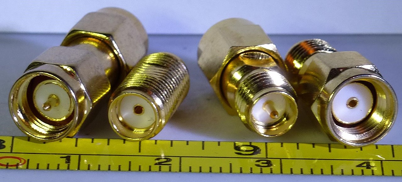 young cove
restive fjord
so without the pin it's useless then ?
young cove
restive fjord
so without the pin it's useless then ?
It's not useless, you just need an adapter from non-RP to RP. These are easy to find on Amazon and elsewhere.
primal warren
Or from RP-SMA to whatever you want to connect to, like AdaFruit product number 852, which adapts from RP-SMA to U.FL.
restive fjord
how can I tell if it's of any quality? Remove the housing, check chips? Or it's just a piece of metal ?<
Could be useful for mobile project to catch wifi from open free ones from the wifi non-profit in the city
random helm
restive fjord
Could be useful for mobile project to catch wifi from open free ones from the wi...
there shouldn't be any chips in it... a whip antenna like that is basically just a piece of electricaly conductive material, generally some form of metal
 fringe crow
Does anybody know how to use the ESP32-S2 ToF feature?
worn bridge
No, but have you seen https://github.com/espressif/esp-idf/tree/master/examples/wifi/ftm ? That might be the example you're looking for, though you'll probably have to use ESP-IDF to access it.
GitHub
Espressif IoT Development Framework. Official development framework for Espressif SoCs. - esp-idf/examples/wifi/ftm at master · espressif/esp-idf
 proud shoal
Hey all, I wanted to get into radio and LoRa and had a question; what is the difference between the RFM69 and RFM95 modules? I was looking at both and couldn’t tell if there was a functional difference between them
granite spear
proud shoal
Hey all, I wanted to get into radio and LoRa and had a question; what is the dif...
I think it's mainly the LoRa support. The '69 only does normal FSK/OOK types of modulation, while the '95 additionally can do LoRa.
proud shoal
granite spear
I think it's mainly the LoRa support. The '69 only does normal FSK/OOK types of ...
Gotcha, thank you so much
urban iris
Hello
Today I measured the spectrumm of rfm9x and I obtained this results

Why ar 2 spectrum, is my tx frequency in 433MHz
primal warren
urban iris
Why ar 2 spectrum, is my tx frequency in 433MHz
Looks like it may be using FSK (frequency shift keying)?
pastel granite
Afternoon everyone 🙂
Long time no speak.
Have a question about converting bytes to string - something is funky in CPy's decode() method.
Anyone around?
primal warren
I just got off work. But that might be a question for #help-with-circuitpython
 atomic patio
Hi everyone! I’m trying to figure out if anybody has had any luck with getting the lora featherwing working with the radiohead library on the rp2040?
primal warren
atomic patio
Hi everyone! I’m trying to figure out if anybody has had any luck with getting t...
I haven't tried that personally, but there's a thread here implying there may be driver issues: https://forums.raspberrypi.com/viewtopic.php?t=224035
normal drift
atomic patio
Hi everyone! I’m trying to figure out if anybody has had any luck with getting t...
FYI -- I have reproduced your problem. If I take working code from a feather m4 express and recompile it for a feather rp2040, it does not receive any packets. I have no idea why...
perhaps this is relevant https://forums.raspberrypi.com/viewtopic.php?t=303896
and this from the Radiohead Library main page Raspberry Pi Pico, on Arduino, using either the Raspberry Pi Pico/RP2040 core by Earle F. Philhower, version 1.93, installed per https://arduino-pico.readthedocs.io/_/downloads/en/latest/pdf/ or the alternative Arduino MBED OS RP2040 core version 2.4.1. At this stage support is partial: RH_ASK works but radio drivers that use interrupts do not (yet) work in either core. https://www.airspayce.com/mikem/arduino/RadioHead/
sly dust
Hello, I've spent a few weeks to go from pico plus airlift issues to https://github.com/adafruit/nina-fw/issues/46 - where I've got a reproducible crash in the NINA-FW. Slightly overwhelmed as that was quite a run around to get this far - but it looks like it's now in the ESP32 IDF which I'm not familiar with.
GitHub
When the ESP32 is used as a server (by CircuitPython, tested on RP2040), it will consistently crash after a few hundred requests. I have narrowed this to being in the NINA-FW and not CircuitPython ...
 tame nymph
Hey there. Can anyone help me understand this data type..how it works?
(char*)buf
It's the data format into which received messages are stored as part of this Lora RFM9X Test example code here:
https://learn.adafruit.com/adafruit-rfm69hcw-and-rfm96-rfm95-rfm98-lora-packet-padio-breakouts/rfm9x-test
I have 2 identical setups and the example code executes fine sending and receiving between the two radios. Specifically, I want to be able to evaluate (char*)buf in a conditional statement and drive subsequent code to trigger. It didn't work directly, i.e*. if (char*)buf == "TurnOnRelay"), so I dumped it into a String like this:
String verify = (char*)buf; if (verify == "TurnOnRelay") digitalWrite(RELAY, HIGH);
It works like this.
I can Serial.print (verify) and the text is correctly received between radios, plus turns on the relay). But as soon as I add additional lines in IF statement, for some reason, it seems to not get the right data in my String variable "Verify". It Serial.prints as either a blank line, or a backwards question mark. Simultaneously I can print directly Serial.print((char*)buf); and get the proper sent text, so the radio communication is happening fine/accurately.
This makes no sense to me, and I've checked and rechecked my code for errors.
I know, in theory, that the asterisk can be used in front of a pointer variable to get the value of the object that is pointed to by the pointer. But this usage doesn't seem the same animal as I have seen in examples elsewhere.
Is there a better/another way to evaluate this received message in code?

Adafruit Learning System
Radio transceiver modules for long distance data communication
primal warren
Char just is a single character. You probably want char * which is a pointer to characters (or, more usefully, a pointer to an array of characters, which is a C string).
tame nymph
primal warren
Char just is a single character. You probably want `char *` which is a pointer ...
So, not sure what's going on with discord but everywhere above I typed (char*)buf which is how it looks if I edit my post, but it is showing without the asterisk?
Are you saying I should do this?
char* verify = (char*)buf;
primal warren
I generally don't use the String class, so to compare strings, I use a function like ```arduino
if (strcmp(buf, "TurnOnRelay") == 0) {
digitalWrite(RELAY, HIGH);
}
Oh man thanks! Wasn't familiar with that, but works flawlessly now! I appreciate it a lot!
 edgy breach
Is it OK to connect the MIC- pin of a FONA 800 to GND?
or is it what has killed the FONA?
edgy breach
I think this has killed 2 FONAs so far,
 bronze lichen
What are you using as input to the MIC+ pin?
primal warren
edgy breach
Is it OK to connect the MIC- pin of a FONA 800 to GND?
Should be: the AdaFruit board grounds MIC1N, so grounding MIC2N should be fine.
 noble tusk
hello! does anyone know where should I find more about raspberry pi zero 2w antenna ?
primal warren
noble tusk
hello! does anyone know where should I find more about raspberry pi zero 2w ante...
There doesn't seem to be a lot of info out there. It's a Niche PCB antenna licensed from ProAnt (like the Zero W antenna was) but an improved design with 2.5dBi gain. FCC ID is 2ABCB-RPIZ2, but the documents available don't add much information. It appears that ProAnt is a division of Abracon: https://abracon.com/niche-antennas

Abracon
Abracon is a leading global manufacturer of passive and electromechanical timing, synchronization, power, connectivity and RF solutions.
 coarse crypt
Can someone please verify the SPI pins? I.e. are they from left to right? For the rmf95 https://learn.adafruit.com/radio-featherwing/pinouts.
granite spear
coarse crypt
Can someone please verify the SPI pins? I.e. are they from left to right? For t...
Looks like it's SCK, MOSI, MISO left-to-right from the schematic.
coarse crypt
granite spear
Looks like it's SCK, MOSI, MISO left-to-right from the schematic.
Thank you very much!!
coarse crypt
Ok all, I have another issue. I have the rmf95 feather wing connected to esp32 thing plus. I have mosi -> mosi, miso -> miso , sck-> sck. CS -> 22, irq ->14, reset->23 , at the top of the arduino sketch i have #define RFM95_CS 22, #define RFM_RST 23, and #define RFM95_INT 14. My code hangs at rf95.waitpacketsent() , are the arduino pins the same as the eps33 pins? Or is there another way to specify the IRQ , CS, RST pins? I must be missing something? 🤔
coarse crypt


I have probed every pad and every pin next to each other and I can find the reason why ground is connected to 3v creating a short. Can someone help explain this? Is the board bad?
primal warren
Does the board not power up?
restive fjord
Hi. I'd like to make 2 gadgets sending (directly or indirectly) bme680's readings over some radio to an android tablet 5-10m away, around twice per second each. A LoRa gateway is not out of the question and some long-term storage for readings would be nice too. The main functionality is to display on the tablet a real-time reading+2-hour graph with ideally no more than let's say 1-2s delay, from both sensors at the same time.
Any radio recommendations? It needs to be as small as possible and low power, so as not to skew the temperature reading (might add a bme390 for better precision) but will be USB-powered (5V).
granite spear
restive fjord
Hi. I'd like to make 2 gadgets sending (directly or indirectly) bme680's reading...
With that sort of relatively short range and for compatibility with off-the-shelf tablets, I'd be thinking BLE rather than LoRa, such as https://www.adafruit.com/product/3406
The Adafruit Feather nRF52 Bluefruit is another easy-to-use all-in-one Bluetooth Low Energy board, with a native-Bluetooth chip, the nRF52832! It's our take on an ...
restive fjord
Ok that's a really sweet looking module actually
at this point I've switched my alignment to prefer a solution with central logging, but wow, one sweet looking tiny module
Ok, so on one hand, with a direct bluetooth connection there's the nRF52832. Any recommendations for a lora-based approach with a gateway?
or is nRF52 the way to go also with a gateway saving to homeassistant, grafana, etc.?
restive fjord
can I have the sensors with nRF52 broadcast readings, so they'll be seen by both, tablet and homeassistant/grafana gateway?
granite spear
restive fjord
Ok, so on one hand, with a direct bluetooth connection there's the nRF52832. Any...
There's a similar board with LoRa instead, for example: https://www.adafruit.com/product/3178

This is the Adafruit Feather M0 RFM95 LoRa Radio (900MHz). We call these RadioFruits, our take on an microcontroller with a "Long Range (LoRa)" packet radio transceiver with built ...
You might also consider the ESP32, which has WiFi (and optionally Bluetooth), since it sounds like you are really wanting to just put these sensors on the network with other stuff.

Aww yeah, it's the Feather you have been waiting for! The HUZZAH32 is our ESP32-based Feather, made with the official WROOM32 module. We packed everything you love about Feathers: built ...
restive fjord
oh right, I kinda want to do the exact thing ESP32 is for... but with less heat dissipation


though really, the most important parameter for me is pressure and accurate temperature is just an extra nice-to-have
ESP8684 has an ESP32-C2 silicon die packaged together with (some amount of) flash in a 4x4 mm QFN-28 package.
 heady scarab
restive fjord
https://imgs.xkcd.com/comics/decision_paralysis.png
heady scarab
restive fjord
https://imgs.xkcd.com/comics/decision_paralysis.png
Bad example... Two people, two cars.
Take both. 😂
 lost gorge
Hey!
i hope i ended up in the right place, im super new to building bluetooth chips,
i have some past experience with NRF24 chips
anyways, cant get my hands on any NRF24 chips, so i got NRF52, which are the latest version of those chips,
so i assumed it should be similar, only problem. unlike nrf24, they hate being flashed with Bin files, and uh, all my files are in bin files,
can someone please help me and instruct me on how im supposed to get these bin files
and turn them into hex files?
primal warren
lost gorge
Hey!
i hope i ended up in the right place, im super new to building bluetooth ch...
If you're using the Arduino environment, the bin file is built with a gcc command, and converted to a hex file with the objcopy command.
On my computer, these are part of the AdaFruit nRF package and are specifically ~/Library/Arduino15/packages/adafruit/tools/gcc-arm-none-eabi/5_2-2015q4/bin/arm-none-eabi-gcc for the compiler, and arm-none-eabi-objcopy (in the same directory) to convert it to hex.
The quickest way to find the locations of the executables and their arguments is to check the "Show verbose output during compilation" option in Arduino preferences, compile something for the desired board, and examine the output to watch the commands used.
 past solar
Is there a significant difference in range between 433 MHz and 900 MHz RFM69HCW devices? I'm a licensed US ham working on a ham radio project. I would like for non-hams to be able to use my device with minimal changes, so I'm considering going with 900 MHz devices, but if 433 range is significantly better, I would use those.
The signals will frequently have to go through walls. The network is similar in use to a cellular network (more like APRS if you're familiar with that), except most base stations will be indoors.
bronze lichen
(I’m not a radio guy so i might be wrong) i don’t think the range would change much because the power of the different modules is almost the same
past solar
I was expecting that the range should be better at 433 (basically, a lower frequency has a longer wavelength, and a longer wave can go around obstructions more easily), but the product pages give the same ranges for both bands.
I'm familiar with VHF and low UHF propagation, and VHF (2 m, ~146 MHz) does travel farther than UHF (70 cm, ~446 MHz; in the same band as 433)
granite spear
You may not have a choice anyway. My understanding is that 433MHz is for Europe and 900MHz is for the US. The former band isn't open for general use under FCC regulations, AFAIK.
past solar
I'm a licensed ham, so I can transmit on 433 under amateur regulations. I can transmit on 915 under amateur or unlicensed regulations, which is why I would prefer 915 (that way I can use it with non-hams), but if using 433 will get longer range, that's okay.
In Europe, it would be okay for non hams to use it on 433.
granite spear
Ah, sorry, I misunderstood, I thought you wanted to build something for non-hams to also use.
past solar
That would be nice, but range is more important. If getting longer range requires users to have ham licenses, I'm okay with that.
granite spear
Are you wedded to the RFM69? If you want more range, the LoRa variant modules in the same family would be an option.
past solar
I might think about LoRa. I know it's a proprietary protocol. Is the RFM protocol proprietary? I would prefer an open protocol, but proprietary is okay if necessary. If the RFM protocol is proprietary as well, I would have no reason not to use LoRa.
Oh, the LoRa modules are too expensive.
granite spear
Not sure about the protocol. I think they have a few different options, including basic OOK or FSK.
past solar
It looks like the RFM chips use FSK, but I'm talking about the packet protocol as well as the modulation.
I guess I could implement my own packet system and use them in raw bit mode. It would be more work, but it would be worth it as a way to avoid a proprietary protocol.
Oh yeah, RFMs can use multiple modulations
 remote pond
oh right, a proprietary protocol might be considered illegal under US amateur radio regulations, possibly?
past solar
I'm pretty sure they're legal (people use proprietary modes a lot, e.g. VARA, PACTOR, D-STAR, DMR, C4FM); I'd just rather avoid a proprietary mode. @remote pond
past solar
(IANAL; that's not legal advice)
primal warren
IAANAL, but my understanding is if the protocol is documented and unencrypted, you don't monopolize or interfere, and you follow the rules for periodic station ID, you'd be in compliance
past solar
@primal warren yeah I think that's right
I would prefer to avoid a proprietary mode, but that's just a personal opinion, I'm pretty sure there's no legal issue
remote pond
ah, ok. i keep forgetting proprietary isn't necessarily undocumented (though do some of them require IP licensing from the vendor?)
past solar
IIUC a reverse engineered spec counts
past solar
It looks like using two separate microcontrollers will be better for my project, with the RFM69HCW in "raw rx/tx" mode, but that mode isn't documented on learn.adafruit.com. I know I would have to implement error correction. Is there some kind of documentation for raw mode?
primal warren
Maybe look at the RadioHead library, which offers a bunch of different operational modes.
past solar
Okay, I'll look. It looks like I could just use a normal serial connection to send and receive bits once it was set up, but I still need to figure out how to set it up.
past solar
Specifically, I want to use it as an APRS transceiver. I know that it won't be RF-compatible with normal APRS radios, but I do want the protocol to be the same so packets from my devices can be relayed to the APRS network and vice versa.
coarse crypt
Hi All, I'm trying to connect to the helium network, I can't seem to find where to put the server information i..e. iPad dress like the ttn network has
past solar
Is it possible to solder a wire directly to an RFM69HCW breakout for the antenna?
primal warren
Yeah, should be. I've done similar things with other boards, with good results.
 bronze lichen
past solar
Is it possible to solder a wire directly to an RFM69HCW breakout for the antenna...
bronze lichen
past solar
Is it possible to solder a wire directly to an RFM69HCW breakout for the antenna...
it's called a whip antenna and yes i can verify it works with rfm69 if you cut it the right length
random helm
AFAIK all the common Ham radio digital modes are proprietary anyway, so I don't see how this would be different. That said I'm just a Technician and not super active; I see you got your Extra, congrats!
 sick carbon
I think that's the major reason for the M17 project's existence
past solar
Most non-voice modes other than PACTOR and VARA are open source
 native sparrow
how would i do radio control for say an RC car. what tutorials could you point me to or boards that do it for me
bronze lichen
what are you using as the controller and what range do you want?
native sparrow
the controller for the vehicle is an arduino mini and the range doesnt have to be huge but not only like 1m
the controller that controls the vehicle is custom
like the one you hold is custom
remote pond
do you already have experience with operating conventional (non-microcontroller) RC models?
native sparrow
yes i can operate an RC model
its a hexacopter btw
like a quadcopter but with more props
primal warren
native sparrow
how would i do radio control for say an RC car. what tutorials could you point m...
There are some tutorials using nRF24L01 chips, there's also the option of the Pololu Wixel, or the approach I ended up going with, using the Lemon RX transmitter and receiver, along with the PJRC PulsePosition library.
native sparrow
I understood half of that so I’m just gonna go with lemon board
primal warren
In short, you can talk to the 24L01 ones with SPI and send whatever protocol you want digitally. The Lemon RX ones are more traditional R/C units, I got one that accepts a PPM stream and transmits it, and a receiver that includes what they call a "HUART" output, that's an asychronous serial data stream.
One of the 24L01 tutorials can be found here: https://create.arduino.cc/projecthub/anasdalintakam/arduino-wireless-remote-with-2-5ghz-nrf24l01-6f9337
 raw mural
https://www.adafruit.com/product/1497 how is this for someone who has never dabbled with SDR or radio in gernal?

If you've ever been curious about software defined radio (SDR), this USB stick is the easiest way possible to have fun with a powerful, configurable receiver. Packed with the powerful ...
past solar
@raw mural that looks good; I have a similar one from a different brand and it works well
(same chip)
 brisk grove
Has anyone ever used Picos (or other RP2040s) in a LoRa situation of any capacity?
normal drift
brisk grove
Has anyone ever used Picos (or other RP2040s) in a LoRa situation of any capac...
I have used the feather rp2040 with an rfm9x and CircuitPython
There were some issues with the Arduino RadioHead library.
brisk grove
@normal drift There are rumors that circuitpython cannot be used to communicate with a LoRa gateway device.
since circuitpython is actively developed, I don't know if this is still true today
normal drift
The CircuitPython TinyLora library does not work with TTN V3 so the rumor is confirmed.
Circuitpython supports LoRa -- not Lorawan
the rfm9x library works for sending LoRa packets.
I have been using the Arduino MCCI LMIC library for TTN V3
brisk grove
Imagine I go ahead and deplloy my own homebrewed LoraWAN network server. Can I end-around this non-support of TTNv3?
normal drift
I have no idea...sorry -- I upgraded my Gateways to V3
brisk grove
hmmm
normal drift
Do you need LoraWan? -- can you just send LoRa packets between your nodes. I use a Raspberry Pi with an RFM9x as my "gateway" -- not using LoRWAn
brisk grove
I need some manner of front-end client app for telemetry (eventually control as well)
normal drift
Does this happen to be for a project at UNH? Sounds like something I talked to folks there about earlier today?
brisk grove
normal drift
Does this happen to be for a project at UNH? Sounds like something I talked to f...
Pardon me! I just now noticed something about your screen name here. Maybe we could continue in direct message?
normal drift
sure
normal drift
Just curious if anyone has found a way to use a feather RP2040 (or any RP2040) with LoRaWAN (TTN V3). I have a working example using an rfm9x featherwing with a Feather M4 express, but when I swap it over to the feather RP2040 (same pinouts) my gateway sees an initial packet from the RP2040, but the RP2040 does not appear to receive the response and fails to connect. If I recall correctly there were also some issues with receiving packets on the RP2040 with the Arduino RadioHead library. Has anyone had any success with RP2040s using LoRaWAN or RadioHead? It works fine with CircuitPython.
normal drift
FYI -- I just tried this example and it works!! https://www.hackster.io/sandeep-mistry/connect-your-adafruit-feather-rp2040-to-the-things-network-5c0c84 Nice to know the RP2040 can communicate with LoRaWAN -- still not sure why the MCCI LMIC library is failing, but this is a big step. The example is great. It uses also shows how to send data to the end device via downlink -- very cool!
normal drift
Hooray! The issue with the MCCI LMIC library has been resolved. I'm still not sure why it was not working with the original pin selections, but I changed to using the same pins as in Sandeep Mistry's example and it now works fine. That is a great relief!
 bold moat
do higher frequency waves hold their energy better? say 5ghz vs 2.4ghz. Would 5ghz be less vulnerable to constructive/destructive interference?
normal drift
Mystery solved regarding the pinouts for the RP2040 -- just had to read the docs There is no pin remapping for Arduino on the RP2040. Therefore, the pin names on the top of the board are not the pin names used for Arduino. The Arduino pin names are the RP2040 GPIO pin names.
normal drift
With the correct pin definitions, the RadioHead Library also works with the Feather RP2040....life is good!
granite spear
bold moat
do higher frequency waves hold their energy better? say 5ghz vs 2.4ghz. Would 5g...
Not much difference there, I'd say.
remote pond
bold moat
do higher frequency waves hold their energy better? say 5ghz vs 2.4ghz. Would 5g...
wave interference is wave interference. one thing that does happen is that diffraction interactions with obstructions varies with wavelength. materials interactions (attenuation, etc) also vary with wavelength
worn bridge
bold moat
do higher frequency waves hold their energy better? say 5ghz vs 2.4ghz. Would 5g...
My understanding is lower wavelengths are less obstructed by solids and liquids in comparison. A house with a lot of walls, for instance, would have better signal coverage with 2.4GHz than with 5GHz. Can't speak for conflicting signals, though.
bold moat
hmm since its dealing with photons (with no mass), maybe the non-classical way to think about it is as a wave-particle and the atoms on the wall with their own surrounding electric fields. So if its too low energy, more of it passes through common materials like brick, timber & steel. But when you increase to 5-6GHz, more photons are 'captured' by the electric fields, causing deflection or absorption. Or maybe Im dunno what im talking about
remote pond
materials interactions with electromagnetic radiation are partially due to quantum resonances at the atomic and molecular levels (sharp absorption/emission lines for atoms, wide bands for molecules, etc)
 woeful vector
hi all, I am looking to work on a persona project with LORA radio,
is there a possibility/option to assign ID per main/secondary Lora so I can couple tthrm?
I will need to make approx 170 couples
thanks in advance !!
granite spear
woeful vector
hi all, I am looking to work on a persona project with LORA radio,
is there a po...
The base LoRa protocol doesn't really have the concept of an address or ID... the radios just receive whatever is transmitted on the channel frequency with compatible parameters. So you'd need to build in an addressing scheme into the contents of your data packets.
normal drift
woeful vector
hi all, I am looking to work on a persona project with LORA radio,
is there a po...
Some LoRA libraries (Radiohead for Arduino or the adafruit_rfm9x CIrcuitPython library) use a packet header that contains addresses.
The header is documented here <https://www.airspayce.com/mikem/arduino/RadioHead/classRHDatagram.html > and here https://www.airspayce.com/mikem/arduino/RadioHead/classRHReliableDatagram.html
 crisp rampart
Hi! I have an ESP32-S3 feather and I'm trying to connect it to my phone. But when I do a Bluetooth scan, it doesn't find my phone's Bluetooth address, nor does it find any devices that have a py complete_name . I put the feather right next to the phone, so they would be close enough to make a connection. What is happening?
granite spear
crisp rampart
Hi! I have an ESP32-S3 feather and I'm trying to connect it to my phone. But whe...
So to check the obvious things first, does your phone have Bluetooth turned on, and is it set as "discoverable" in the Bluetooth settings?
woeful vector
granite spear
The base LoRa protocol doesn't really have the concept of an address or ID... th...
Kid there any other radio that would cover 1000m range and it support addresable messages ( even if the address is in code ) ?
crisp rampart
granite spear
So to check the obvious things first, does your phone have Bluetooth turned on, ...
Bluetooth is on, but I can't find a "discoverable" option. I have a "+ Pair new device" button, and when I click it it searches for devices. Is that the right one?
primal warren
woeful vector
Kid there any other radio that would cover 1000m range and it support addresable...
The ordinary 315/432MHz ones with even simple wire antennæ can manage that (I've done it).
 woeful vector
primal warren
The ordinary 315/432MHz ones with even simple wire antennæ can manage that (I've...
woeful vector
primal warren
The ordinary 315/432MHz ones with even simple wire antennæ can manage that (I've...
What range you get ?
primal warren
About 1100m, over open but not flat terrain.
crisp rampart
granite spear
So to check the obvious things first, does your phone have Bluetooth turned on, ...
I clicked the "+ Pair new device" button and over time my phone finds a few bluetooth devices, e.g. an Apple TV, the Chromebook I am coding on, but not the Feather even when the Feather is on.
granite spear
Is the Feather running software that makes it discoverable and handles the pairing?
crisp rampart
I don't think so. It's iterating through ble.start_scan() and storing the advertisements in the variable ad. I could do connection=ble.connect(ad) but for that to work the feather would need to see the phone over Bluetooth and have the phone's advertisement in the variable, which is the problem.
bronze lichen
Is your phone ios or android?
woeful vector
_I could really use some help with SIM868 and AT commands, I am trying to get to send an HTTP POST request with micropython I am using pico and https://www.waveshare.com/wiki/Pico-SIM868-GSM/GPRS/GNSS
primal warren
It might be worth looking at the FONA library source code to see what AT commands it uses.
woeful vector
primal warren
It might be worth looking at the FONA library source code to see what AT command...
That the arduino lib?
primal warren
That's the one I cribbed info from, but there could be a Python variant that might need less translation
 limber vigil
I have a Feather M0 Wifi (ATWINC1500) board here, but running the firmware check example sketch, it says there's no wifi shield present. Does that mean my wifi chip is dead? I vaguely recall bricking one a few years back, this might be that one. Is there any way to force a firmware update to it?
Ah! I ran the updater anyway, that seemed to work, and now the version check passes.