#show-and-tell
1 messages · Page 6 of 1
 half marten
 wind nest
this is for education, most ones for this sector have micro usb so it saves a lot on cables for a class if they have some also usbc has a higher bom due to the cc1 and cc2 resistors
i may make two versions though
the cost is also very low so this saves a bit
 exotic sierra
wind nest
this is for education, most ones for this sector have micro usb so it saves a lo...
exotic sierra
wind nest
this is for education, most ones for this sector have micro usb so it saves a lo...
At scale 2 resistors is pretty negligible in cost. Buying a reel of 5000 costs like $25 last I bought. The type C socket is definitely pricier but there are some affordable options that end up being like $0.15-$0.20 a piece
wind nest
exotic sierra
At scale 2 resistors is pretty negligible in cost. Buying a reel of 5000 costs l...
the issue is assembly time the reels i get are 5 dollars per reel anyways. it is more of a logistics thing as there is a cost to parts and keeping track of them and maintaining stock.
also the usb if cost is more
exotic sierra
What do you mean usb if?
wind nest
the lisence to use usb
exotic sierra
Like a VID/PID?
If your project is open source you can get a free one from https://pid.codes
I should know, I have 7 allocated
wind nest
Yes i have an old style given to me from an old company shutting down new ones are non transefrable but the one i have is and it is very limited due to the old conditions
they limit the new standards that can be used
exotic sierra
USB 2.0 type C ports exist which happily are compliant
Just don’t do SS/Lightning 🙂
wind nest
the issue is pd is not for the lisencing i have alotough i may purchase a new one
its a really bad lisence i knoe
*know
 clever stone
wind nest
the issue is assembly time the reels i get are 5 dollars per reel anyways. it is...
clever stone
wind nest
the issue is assembly time the reels i get are 5 dollars per reel anyways. it is...
If you are manually assembling, the microUSB is easier with a lower ratio of rework.
exotic sierra
clever stone
If you are manually assembling, the microUSB is easier with a lower ratio of re...
With some of the cool paste application setups I’ve seen, you can get USB type C perfect almost every time
I think my type C success rate is like 90% or better
there is inevitably one board where I somehow get too much paste through the aperture lol
clever stone
exotic sierra
With some of the cool paste application setups I’ve seen, you can get USB type C...
90% is still 20 boards out of 200. A tiny lapse in attention and that 90% can drop to 85% or 80%. Now it's 30 or even 40 boards needing rework.
I use USB-C. That said, the larger spacing and reduced number of pins with microUSB will statistically be easier and have a lower rework ratio.
exotic sierra
Exactly why I may build 10-15 boards in a sitting
If I do that, I usually can get better results because less chance for paste to build up on the bottom of the stencil
But if I’m trying to get a lot done, that’s where my precision drops
clever stone
The underside of my stencil rarely gets paste but once it does it's time to stop everything, clean, and reset.
My typical session is 100-150 boards but I will have the occasional marathon session._ I have a marathon coming up 🙄_
exotic sierra
I don’t have a super great pasting setup so ~5 in, I need to clean. Downside of not having something that can apply constant and even pressure
clever stone
Yeah. I only have one of those manual 3040 solder paste setups. I've done several mods to it so it's tight but often, the PCBs are not perfectly flat so it's a challenge.
exotic sierra
Yeah, on the occasions I don’t splurge for ENIG I tend to have worse results over longer periods of building
Lead free hasl tends to be my go to for boards I don’t consider to be more “premium” or needing.
clever stone
I do ENIG for my production boards but when I'm doing boards for others, it's their call what they can afford.
exotic sierra
One of my better paste sessions
 wind nest
The failure rate is defiantly important also usb c dosnt like cheap paste
wind nest
exotic sierra
I think my type C success rate is like 90% or better
very poor sucsess rate not acceptable at all
exotic sierra
wind nest
very poor sucsess rate not acceptable at all
90% is amazing when you are assembling by hand, it’s all relative.
And rework is usually very minimal
Paste, even good paste, doesn’t always guarantee it will flow perfectly
wind nest
exotic sierra
90% is amazing when you are assembling by hand, it’s all relative.
i have 0.1% faliure rate
bit i have my own footprints to help and adjusted paste layers
exotic sierra
So when you assemble 1000 boards by hand (pretty lofty achievement if you’re doing it all in a single day), you have only 1 failure ever?
That’s basically automated assembly line quality work there, congrats
clever stone
exotic sierra
So when you assemble 1000 boards by hand (pretty lofty achievement if you’re doi...
That is commercial assembly line statistics.
(1000 boards in a day and a modest 50-60 components per board means placing 7,500-10,000 parts per hour ... which is commercial grade PnP territory)
I can trace back nearly 100% of my failures / rework to solder paste application. Unfortunately, the cost jump from a manual paste printer to something with greater accuracy and repeatability is much greater than my investment threshold.
exotic sierra
clever stone
That is commercial assembly line statistics.
(1000 boards in a day and a modest...
Yeah, 1 in 1000 is pretty good for commercial assembly line. Comes out to 1000dpm which according to Assembleon is average 10x the average they should for, 25-50dpm is the goal
But Assembleon machines are used to assemble boards with a lot more components on average than most people would be doing by hand
wind nest
exotic sierra
So when you assemble 1000 boards by hand (pretty lofty achievement if you’re doi...
I do a hybrid pick and place and hand method with my diy pnp but i can only place passixes and other small parts
exotic sierra
I’d love to see your PnP, I really love the idea of having a diy PnP
wind nest
it is a modified lumenpnp
exotic sierra
Oh cool, Lumen is pretty nice
wind nest
but i have added more precise linear motors instead of steppers
wind nest
exotic sierra
So when you assemble 1000 boards by hand (pretty lofty achievement if you’re doi...
In this case the design is made for assembly eith large spacin i also change footprints and the paste layer it really helps
exotic sierra
Yeah, it’s a cute little board. I love the large pads you provided on the edges
Perfect for alligator clips (which I would guess was a primary motivator for the choice)
wind nest
Yes it way
was*
the main factor with the design is cost as it will sell at $15 but for instance i sell to digikey at $10
 daring timber
I've added an on-line code editor for the RP Pico today (RP2350/RP2040):
https://flashmypico.com/editor?from=a2548a38-4800-411a-b1cf-c70ee427f60f&device=pico_2
wind nest
Looks good
 dire axle
Designed a case for the Xiao ESP 32 S3 Sense to be mounted on my Prusa Mini and MK4S. Runs Circuitpython which sends images to Prusa Connect using REST API.
Thanks to @cunning lava for pointing me in the right direction and getting the espcamera library to work on the board.


 wind nest
great
 night peak
Got a pure python HUB75 library working for bare metal Raspberry Pi Zero CircuitPython (and mimxrt10xx boards) 😁



GitHub
A pure Python library for driving HUB75 type RGB Matrix panels - RetiredWizard/RGBMatrixDisp
 bitter dome
night peak
https://github.com/RetiredWizard/RGBMatrixDisp
bitter dome
night peak
https://github.com/RetiredWizard/RGBMatrixDisp
cool demoscene stuff
 untold briar
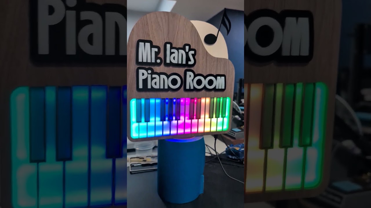
I got some help here recently to get parts of this project working, and I am so proud of how it turned out! This is a Piano that plays a few different songs, and the correct notes light up when they play 🙂 This was a gift for my daughter's piano teacher. Not all of the parts are from Adafruit but a lot are, hope that's okay to share here 🙂
Code, SVGs and write up here: https://github.com/jmauerhan/piano
Video of the LEDs and the music: https://www.youtube.com/watch?v=4fef2JDTV4o


GitHub
Audiovisual Piano Art using MicroPython & Neopixels - jmauerhan/piano
 wind nest
looks great
 runic sorrel
Reverse engineering the OOK signals for an iVac controller (dust collection in the shop), built a PCB to do it and have an opto-isolated input so my CNC can control it.
Why spend 100$ on their solution when I can make a project out of it and spend 100$ on 5 of them 😄 Plus looks like their solution is 5V input only, my CNC (AltMill) will be 24V control.

 high imp

▶ Subscribe: https://www.youtube.com/channel/UCqyPRKnXxjDJOQAXV__6yNw
Click the Bell Icon to get notifications about my future videos!
Link to KiCad 7.0 files
https://github.com/mortens-lab/HUB75-PICO-shield
▶Refererral link:
https://pcbway.com/g/i8683S
▶PCBWAY : https://www.pcbway.com
#rp2040 #pico #kicad
 fast knoll
Here is a schematic for a media player game console prototype powered by the rp2350 with 4mb psram and a PCM5102 DAC

I actually added a voltage divider after I took this screenshot to measure battery percentage
fast knoll
I will probably remove the ferrite beads since the 3.3v power shouldn’t be noisy anyway
 latent snow
Nice @fast knoll
Check it out, friends! I have all of the parts of my projects together for the first time. Exciting milestone


Complete with sensors: 9-DOF IMU, GPS, atmosphere pressure/gas/humidity, Gesture / Prox / Color
IO: 1x4 neokey and rotory encoder with momentary
Blinky: I2c neopixel driver for the multitude of LED's
I wrote a client that collects from the sensors and exposes them as an http endpoint in a prometheus format, that I then scrape into a database and display as a dashboard

the GPS stuff is way cool - I went for a walk and I'm amazed at the accuracy of the sensor. I mean, I guess I shouldn't be surprised - but it's still pretty cool to see a point with my position every second. Next I'm working on making a PCB to hold and connect all the parts.

 sacred timber
latent snow
Complete with sensors: 9-DOF IMU, GPS, atmosphere pressure/gas/humidity, Gesture...
sacred timber
latent snow
Complete with sensors: 9-DOF IMU, GPS, atmosphere pressure/gas/humidity, Gesture...
What does it do? I’m curious since GPS doesn’t usually work indoors, so is this for some kind of outdoor installation?
 north mural
Made a Matrix Portal S3 RTC clock on a matrix panel. It is very accurate with NTP synchronization once an hour.
 round wharf
Happy to finally have this working, wrote an interactive script to, convert, send and manage files to send over to it from my PC. 2x 32x64 2.5mm panels vertically chained. Next job is to 3d print a frame!

 severe pine
I've been working since roughly October 2024 or so on this design. I call it the TechnoPico, named after the 9-button arcade dance game TechnoMotion! It's designed to work with just about every arcade-style dance game that can be played in a minimum 3x3 panel layout. Switches are hotswappable, and can be removed to match whatever layout you want to play with, if you so desire.
It's based on the RP2350 and currently runs CircuitPython/KMK, with support for QMK and dedicated arcade I/O emulation firmware options in the works! You could even use it as a macropad so it doesn't waste desk space when you're not playing!


 fast knoll
severe pine
I've been working since roughly October 2024 or so on this design. I call it the...
fast knoll
severe pine
I've been working since roughly October 2024 or so on this design. I call it the...
Did you salvage the standalone MCU from a pi pico 2?
severe pine
Nope, ordered pre-assembled from JLCPCB
fast knoll
severe pine
Nope, ordered pre-assembled from JLCPCB
Oh, so you’re able to get the cpu from JLCPCB?
severe pine
Sort of - you have to email customer service and ask really nicely if you can lol
They aren't fully publicly available yet
fast knoll
severe pine
They aren't fully publicly available yet
I know
I can’t wait until those MCUs come out though
 gusty ravine
Just did my first arduino project.
Bits used:
- (2x) 127cm 5v rgb led light strips
- Arduino UNO clone
- (3x) C3856 transistors
- Jumper wires
- Heat shrink (Always use heaps of it)
- 3d printed arduino case
Wanted to have led strips behind my tv and for a certain colour to be on when it received power.
I didn’t have any mosfets, I did just find a cache of C3856 transistors and those worked lovely.


 solemn ferry
Hi all, hope you are well. I’m pretty sure I made the World’s Smallest STM32 breakout board:
https://youtu.be/J5UEUX3euWQ?si=gJoBMSEbkTXD8cIZ
of course, I know stm32 and esp32 are in completely different classes, but I put that in the title for more views lol
Let me know what you think 😁
it uses WLCSP package and scores 1023 on CoreMark, so pretty fast too 👍

Thanks to PCBWay for sponsoring this video! Get $5 of New User Free Credit by following this link - https://pcbway.com/g/x5f10h. PCBWay is one of the most experienced PCB manufacturers in China, consider them your one-stop solution that offers PCB fabrication, turn-key PCB Assembly, PCB design, 3D printing, and CNC machining services.
In this v...
 smoky heath
solemn ferry
Hi all, hope you are well. I’m pretty sure I made the World’s Smallest STM32 bre...
smoky heath
solemn ferry
Hi all, hope you are well. I’m pretty sure I made the World’s Smallest STM32 bre...
Watched the video but didn't see it. Where is it exactly?
 vagrant shard
solemn ferry
Hi all, hope you are well. I’m pretty sure I made the World’s Smallest STM32 bre...
vagrant shard
solemn ferry
Hi all, hope you are well. I’m pretty sure I made the World’s Smallest STM32 bre...
one thousand dollars!? (joking)
solemn ferry
vagrant shard
one thousand dollars!? (joking)
lol, a lil rounding up was done there... Via-in-pad and 3mil trace width/clearances aren't cheap though 🙂
vagrant shard
I figured it was one dollar, but using comma as a decimal place? is it actually that expensive?
solemn ferry
vagrant shard
I figured it was one dollar, but using comma as a decimal place? is it actually ...
It was a few hundred dollars for 15 boards including 5 of these and 10 of other designs I put in the panel, all using via-in-pad and those tight clearances, which I conveniently rounded up to $1000 to make it sound more appealing. Per board, it is more like $60. But, considering starting costs for manufacturing, you might as well call it $1000 and try to squeeze a few extra views out of the algorithm. lol 😂
vagrant shard
wow, here I was thinking you got the cost down to a dollar per board
 dark cairn
Has anyone ever wondered what would happen if we were to make an mcu minicomputer?

Like, every module in cards
I could literally do the same card style for nordic and rp2 and since it's all 3v3, it could work on the same base board
For boards without native usb, it'd be possible to just make a ch340c to usb card
PSRAM upgrade in card, GPIO on another, DVI on another, ethernet and even featherwing cards, so you can plug even more things in there.
It would also be possible to do flash cards, so we could have swappable mcu storage
Like, for prototyping this will be epic
And even for production, 2 slot carriers could be used to reuse mcu card modules and only add io extenders
exotic sierra
dark cairn
Has anyone ever wondered what would happen if we were to make an mcu minicompute...
In some ways, it does remind me of how they do some of the Z80 computer kits these days
 cedar trellis
dark cairn
Like, for prototyping this will be epic
cedar trellis
dark cairn
Like, for prototyping this will be epic
That's pretty much what MikroElektronika Click boards are doing https://www.mikroe.com/click

MIKROE
1700+ mikroBUS™ add-on boards with all types of sensors and transceivers. No wires, no soldering, no time-wasting. Libraries and examples available.
dark cairn
cedar trellis
That's pretty much what MikroElektronika Click boards are doing https://www.mikr...
Oh, never heard them before.
Yea that's the idea, but i'll make even the power boards seperate, so you can do ethernet on one card and poe to 12V in another and then finally 5V to 3v3 in yet another card.
MCU cards like the once I'm starting with will be optionally populated with all of the above so they can work solo, but the idea is that you can just put the bare module, without any power regulation on a single card and call it a day
dire axle
Here are the print files for the Xiao ESP32 S3 Sense 3D Printer Mount, should be able to be mounted to most Prusa printers or printers with a 3030 aluminum extrusion.
https://www.printables.com/model/1181441-prusa-mk4smk4mini-camera-mount-for-xiao-esp32-s3-s

Printables.com
A camera mount for the Xiao ESP32 S3 Sense | Download free 3D printable STL models
 lean elbow
Just posted my guide on Adafruit Playground to build a 'MiniMarquee' WiFi scrolling text display https://adafruit-playground.com/u/squid_jpg/pages/guide-build-a-minimarquee-wifi-text-scroller. The MiniMarquee serves up a local web page for changing the message and other settings, but I also wrote a small iPhone app in SwiftUI to interface with it. Full build instructions and all source code linked in the note 😄

 ancient skiff
49152 LEDs, pi5, python

 worn topaz
I wrote a script to go hand in hand with this 32x32 pixel art project:
https://learn.adafruit.com/32x32-square-pixel-display/overview
You can find the python here:
https://github.com/Whee30/GIFToVerticalBMP/tree/main
I have been getting my GIFs through the divoom app. This script pulls them apart, resizes them and then saves them in a compatible format. Leaving it here for other people searching for info on this fun project!

Animated sprite sheets never looked so good!

GitHub
Script to pull apart animated GIFs and recompile them into vertically stacked BMP files. To be used for building files for an Adafruit 32x32 LED Pixel Display project: https://learn.adafruit.com/32...
 knotty trail
https://github.com/lillianames/Wheelchair_lights
I made an indicator light for my wheelchair that is controlled by a webpage on my phone. I'm already planning a 2.0 version using a motion sensor to run the lights automatically based on movement.
This is what I have so far; raspberry pi zero wh, waveshare 4x8 rgb led hat connected to a webpage control panel set up on a mobile hotspot.

GitHub
Wheelchair_lights that mount to the back of the wheelchair seat - lillianames/Wheelchair_lights
dark cairn
Made a cursed CircuitPython class, thing.
Private variables, exec() with limited, or read-only scope, that works even with objects.
We can have safe exec().
This is still work in progress, but works perfectly.
 regal dagger
i think i figured out the audio issue i was having on show & tell, so i hope to try again next week, but meanwhile for those interested, here is the first stream i did with my first circuit bend project:
https://www.twitch.tv/videos/2347291515

Twitch
vjpcat went live on Twitch. Catch up on their Art VOD now.
lean elbow
I've been hacking around for the last couple of days on writing a SwiftUI iOS app that talks to a Circuit Playground Bluefruit running CircuitPython. Here's a little demo of a custom interface and two-way interaction between the app and the CPB
 onyx glade
Video: Adafruit Crickit Rover No 3D printing needed, LEGO based : https://www.youtube.com/watch?v=umOYiWw2UAc
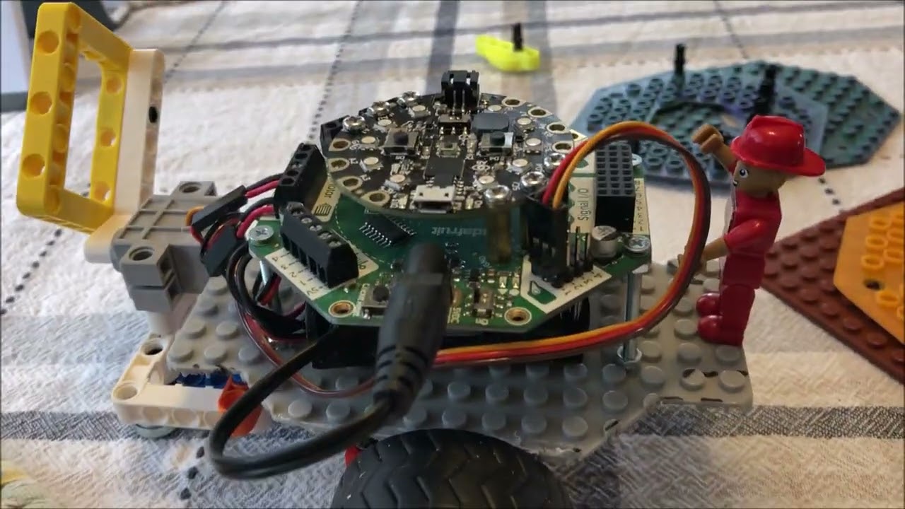
https://tinyurl.com/5n6edpep : The link to Adafruit Crickit Rover Project. They have the coding on this link which you can change for yourself. Dollar Tree store sells the base plate for $1.25. Make sure that it has the 'tubes' on the under side. Adafruit also makes a Crickit for the Microbit, the Crickit costs $29.95 . You can buy the Circuit...
 humble sonnet
https://youtu.be/8d01ShOvVkA?si=Bf9l8YolKbWddPfq pc to Android port and also want to raspberry pi after , opengles 3.0 but can be downgraded to opengles 2.0 , have #140 shaders model running on PC gcc windows mwing

OpenGLES 3 , and C++ with sprite quads and lite physics porting from C++ mwing
humble sonnet
I remember trying to replicate the fbo fb1 in /dev/fb0 to try to do some little screen and lost my pirate pi because of the gamepad as rPi zero project
 sharp comet
got some ideas from deep dive last night and hacked together a displayio Label(ish) class that supports emoji
emojilbl = EmojiLabel("Circuit😎Python\nE🐍m💾o💻j💙i")
 exotic sierra
Finally took the 10 minutes to get this light working I made last year so I could put it up in my kids room. It functions as a night light using an ambient light sensor to determine if the lights are on or off. ESP32-S2 driving it though I eventually want to update to a newer ESP32.

 clever stone
exotic sierra
Finally took the 10 minutes to get this light working I made last year so I coul...
clever stone
exotic sierra
Finally took the 10 minutes to get this light working I made last year so I coul...
The end effect is stunning!
exotic sierra
clever stone
The end effect is stunning!
Funny enough, I don’t think I could 100% replicate the effect because the filament had a higher moisture content than it should have (came that way out the box) and as it was printing it was making tiny pops when doing the edge for diffusing the light.
clever stone
exotic sierra
Funny enough, I don’t think I could 100% replicate the effect because the filame...
Convenient accidents 🤩
I played some with wall thicknesses, infill styles, and layer heights when I was trying to make the diffuser back for my 2023 eChallengeCoin which had side emitting discrete R-G-B LEDs.
It isn't easy getting that perfect translucency 🤞🏼
 glad roost
dark cairn
Has anyone ever wondered what would happen if we were to make an mcu minicompute...
glad roost
dark cairn
Has anyone ever wondered what would happen if we were to make an mcu minicompute...
also, micromod? https://www.sparkfun.com/catalogsearch/result/?q=micromod
dark cairn
glad roost
also, micromod? https://www.sparkfun.com/catalogsearch/result/?q=micromod
oh is that not real m.2?
oh well
glad roost
dark cairn
oh is that not real m.2?
it's the connector
I don't know more about what pins they use for what. I would hope maybe power/ground etc. are the same
as "real" M.2
 wide ember
Basically, my purpose for joining here is to get my extension of GNU Unifont https://stgiga.github.io/UnifontEX to serve as the font in a character LCD.
 limber pendant
some buttons pads for a board on a cyberdeck im working on
 wide ember
This is how not to write a web app, from experience: http://b3k.sourceforge.io
clever stone
limber pendant
some buttons pads for a board on a cyberdeck im working on
Will these touch pads be activated directly or do you plan to put a soft button of some sort on top of the pad?
limber pendant
Reusing ds lite buttons and membranes!
dark cairn
dark cairn
Has anyone ever wondered what would happen if we were to make an mcu minicompute...

 kind burrow
From Tim (Foamyguy), I modified the Feather RP2040 USB Host guide code for a USB keyboard. Working nicely for me 😀 Thanks Tim!
keycodes goes in lib

 graceful glade
Hi all! i’m new to this group and wanted to share my biggest electronics project to date! A full size rocketpack from the Rocketeer. Features a fully custom built tiny fog machine with fans to blow the smoke out, lit by two animated LED rings! Both systems (fog/LEDS) are triggered by buttons on the gloves
 leaden orbit
instructions unclear: my eurorack keyboard looks a bit different to everyone else's?
https://hackaday.io/project/199159
 gusty ravine
leaden orbit
instructions unclear: my eurorack keyboard looks a bit different to everyone els...
gusty ravine
leaden orbit
instructions unclear: my eurorack keyboard looks a bit different to everyone els...
This is lovely ☺️
onyx glade
Video: Adafruit Crickit with Micro:bit and Free Remote Control app. Beginning of Rover build LEGO compatible with no 3D printed parts: https://www.youtube.com/watch?v=CiFZTvriJEc

https://tinyurl.com/ypph4d9z : This code is for Micro:bit V2 and the BST M_Bit app. Find it on Google Play or the Apple app store.-free app. I use Crickit "tank motor" to drive the wheels; both for Micro:bit and for Circuit Playground Express(CPX) controllers . We can also run servo motors with this M_bit app. Look at our other videos on CPX...
 grand jay
leaden orbit
instructions unclear: my eurorack keyboard looks a bit different to everyone els...
grand jay
leaden orbit
instructions unclear: my eurorack keyboard looks a bit different to everyone els...
that has serious cold war spacecraft flight control vibes
leaden orbit
grand jay
that has serious cold war spacecraft flight control vibes
that means a lot 😇✨
 vital basin
Hey folks, I'm a hobbyist programmer and really love collecting different boards and seeing what they're capable of. I made a little library of helper functions to make it easy to analyze new boards and test basic functionality. Easy stuff for experts, but I still find this helpful to return to each time I dust off the hobby and build something new. I hope it helps someone else out, too.

GitHub
A collection of CircuitPython utilities and helper functions to help you get more done with less effort. - HowdyMoto/CircuitPython-Utilities
exotic sierra
Little weekend project 🙂
 onyx glade
Video: Adafruit Crickit Rover in the classroom: 10 yr old explains her coding, MakeCode and Micro:bit. LEGO based rover 2 wheel bot. https://www.youtube.com/watch?v=nCDIjfrmTzI

Bella explains how she added Neopixel colors to the M_Bit app so they change colors as she drives the Rover. The Adafruit Crickit board has one RGB Neopixel LED.
 sand grotto
onyx glade
Video: Adafruit Crickit Rover in the classroom: 10 yr old explains her coding, M...
sand grotto
onyx glade
Video: Adafruit Crickit Rover in the classroom: 10 yr old explains her coding, M...
@teal roost interesting to see the blockly usage, and both an adult and child perspective
 teal roost
sand grotto
<@331195008915079170> interesting to see the blockly usage, and both an adult an...
teal roost
sand grotto
<@331195008915079170> interesting to see the blockly usage, and both an adult an...
I really like how they flipped back and forth between code and blocks to learn by experimentation
sharp comet
kind burrow
From Tim (Foamyguy), I modified the Feather RP2040 USB Host guide code for a USB...
Nice! Thanks for sharing this 
TIL you can change the color of the default terminal display

 sour valley
What is the show and tell link?
I'm listening on linkedin, but cannot find the linke.
 short summit
sour valley
I'm listening on linkedin, but cannot find the linke.
short summit
sour valley
I'm listening on linkedin, but cannot find the linke.
It's posted in #live-broadcast-chat
sour valley
Thanks!
kind burrow
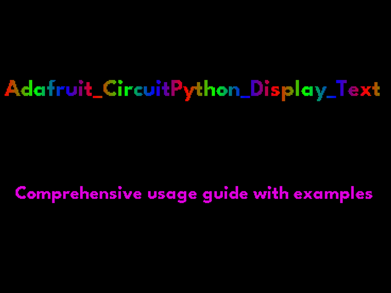
Once again, thanks to Tim/Foamyguy I have a short cute code , where he showed me how to rainbow a bitmap, which I then expanded to fill the whole display with, and throw in NTP current time retrieval layered on top, and movement just for grins. Layering white text on the rainbow is beautiful...
Here is his learn guide page code on that inspired me - it's at the bottom, the example code for Advanced Color Masking.
https://learn.adafruit.com/circuitpython-display_text-library/types-of-labels
Ignore the ugly rubber band, long story... It's a cap touch shield

Get your text looking just right with displayio
 sudden sail
leaden orbit
instructions unclear: my eurorack keyboard looks a bit different to everyone els...
sudden sail
leaden orbit
instructions unclear: my eurorack keyboard looks a bit different to everyone els...
This is so insanely cool!
 tacit cave


 languid nebula
Sparkle Motion board using WLED to drive a 16x16 Led Matrix (Scrolling text effect) and showing TMP117 temperature data send by a TFT ESP32-S2 using the requests library
sudden sail
tacit cave
This looks really great!
sudden sail
languid nebula
Nice! I recommend trimming the significant figures. That sensor has at best 0.1C accuracy.
 delicate geode
The “MusicalMarlin”, named as such because I originally intended to use Marlin as the software: but transitioned to Circuitpython after it was found that Marlin didn’t fully support the RP2040. Can run any midi file, as long as it has 3 channels to be played on the 3 steppers. The messy interior is both a result of my lack of skill and the many attempts I had to fix the issue of extreme interference on one of the motors - which was eventually solved by placing several rubber bands around the motors (?????). The other (negligible) problem is that you have to respect its personal space. Putting your hand near the side of it causes the interference to crop up again. But ignoring that easily ignorable issue, it’s finally done :)
delicate geode
Update: added stepper direction indicators
sharp comet
nyan cat flappy bird style game in progress. 🏳️🌈 😸. Displaying on a TV, running on Metro RP2350.
exotic sierra
The crazy thing about nyancat is that the page got turned into an NFT
But it holds a special place in my heart from when it first rocked the Internet
clever stone
Shout out to LadyAda for recommending the Nordic PPK2 for power analysis (and a lot more).
At first, the 230mA spikes were baffling as no component on the board would consume or handle that much power. Then I remembered my trick for boosting the IR LED output. Those spikes are IR data transmissions.


 idle notch
Sending mouse input to simulate mouse movements using serial com from computer for adafruit rp2040 with usb host smooth as butter

 vernal ferry
Just sharing, not my project.. but.. Lumon Industries WoeMeter is made with Adafruit products!!  https://make3.co/work/woemeter

Severance is renowned for its distinctive production design, and we were tasked with bringing the WoeMeter to life—from early sketches to a fully func
 brazen garnet
Got a working working prototype of my esp32 macropad 🙂
 clever stone
brazen garnet
Got a working working prototype of my esp32 macropad 🙂
clever stone
brazen garnet
Got a working working prototype of my esp32 macropad 🙂
Looks excellent and "tight" (as it well put together). What display will you be using?
brazen garnet
@clever stone Thanks! I am using the rounded 1.69" display 🙂 https://www.adafruit.com/product/5206
Don't be such a square - throw a curve-ball into your electronics with a curved-edge miniature display. Here's a new "round rect" TFT display - it's 1.69" ...
 zealous eagle
Another WLED square pixel display with Sparkle Motion Mini, drawing paper and a mylar sheet for diffusion. Super fun!

 hazy mesa
Not my project, but rather a video that just dropped from one of favorite content creators on YT. And to my lovely surpise, he discovered Adafruit and CircuitPython for this project. https://www.youtube.com/watch?v=kqXIMVjhTUk

Ever wanted your own brain-computer interface? Now’s your chance!
We’re building a Cyberdeck Brain Scanner – a DIY gadget straight out of a cyberpunk story that reads your brainwaves in real-time.
From concept planning and 3D printing the custom case, to sourcing the modular internals and coding the interface.
Follow along to see how I trans...
 spring pulsar
zealous eagle
Another WLED square pixel display with Sparkle Motion Mini, drawing paper and a ...
spring pulsar
zealous eagle
Another WLED square pixel display with Sparkle Motion Mini, drawing paper and a ...
That looks awesome. What kinda of mylar sheet are you using? Trying to find something for a project of mine.
zealous eagle
spring pulsar
That looks awesome. What kinda of mylar sheet are you using? Trying to find som...
Thanks! I was actually disappointed with the mylar sheet on its own, even doubled up. It let too much light through for the square pixel effect, but looked good over the drawing paper diffuser I used. Here’s the amazon link. I see now the product description does say clear mylar, so maybe I should of shopped around a bit…
spring pulsar
I've been using wax paper (since I have a kitchen full of it) while I try to find something real. I need something rigid that won't tear
 woeful depot
I made a musical-midi-miniature-mech model. Uses circuitpython on a pico and a SPOKE board to turn metallic objects into capacitive touch sensors.

In this video I build a model of a mini-mech robot that also happens to be a capacitive touch midi-controller.
It uses a SPOKE-mini board to handle all of the software/hardware https://www.spokeboard.com/
All of the music in the video was created using the final model.
high imp
Make a 100MHz 24 Channel Logic Analyser from your favorite Raspberry Pi Pico
https://youtu.be/Obd1PiW7RO8
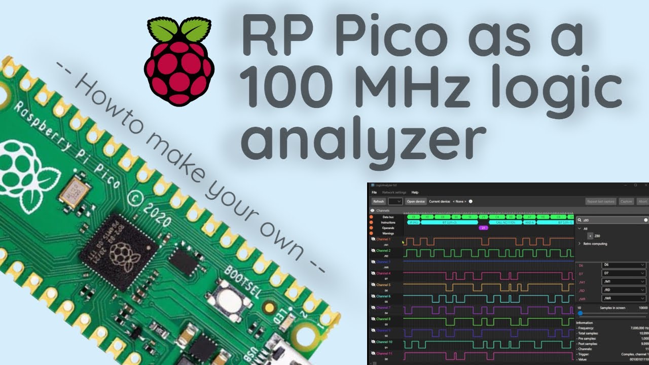
Thanks PCBWay for sponsoring this video - https://pcbway.com/g/i8683S - Use this link for $5 new user free credit.
In this video you will learn how to setup the Raspberry Pi Pico so it can be used as a 24 channel signal analyzer. You will also see some examples using the signal analyzer decoding some different protocols like a UART, I2C-bus and...
sacred timber
spring pulsar
I've been using wax paper (since I have a kitchen full of it) while I try to fin...
You can also take clear acrylic and sand it with very fine grit sandpaper. On the underside so that fingerprints won’t affect the surface.
spring pulsar
Ooohhh interesting
 lusty root
I made a 3D printed RC car with a custom PCBA

 wide musk
I've been updating my TOS Tricorder... Still not done - will it ever be? 😥

In 2017, I began to build my functional Original Series Star Trek Tricorder using a Diamond Select Tricorder toy. Though the main build was completed in 2021, I have since made some significant updates!
Here are the links mentioned in the video:
https://github.com/oldblackcrow - All the code resides here. I have product lists and everything!
h...
 lucid bloom
Its always fun when you find a new use case for an old project and I revamped the case design and software. Its almost done I just built the Protean today so now its testing time.
https://makerworld.com/en/models/1169642-p0w2-hud-scope-case
https://github.com/matt-desmarais/P0W2


This is the case for a HUD scope for the Protean Blaster. Inside the case there is a pi zero 2, berryIMU, quuik shim, waveshare ups. There is also an 8bitdo zero 2 gamepad. The case/electronics are connected to a Vufine heads up display via a micro to mini hdmi cable.The code for the project is available here which is stilll a work in progressht...

GitHub
Contribute to matt-desmarais/P0W2 development by creating an account on GitHub.
 remote sigil
I spent about a month modelling and refining this little guy. He has room for an LED in the eye socket, I'm currently working on a modification for the body so I can store a QTPY inside with a small LiPo 🙂
 sharp comet
All buttons and color packets working. Bluefruit connect packets sent over websocket instead of BLE. Server is running on the picow with web front end viewed by another device on the network.
lean elbow
Wrote a Playground about my latest project, a CircuitPython firmware to transform a Keyboard Featherwing with an nRF52840 Feather into a customizable universal BLE keyboard/mouse/remote control. Check it out at https://adafruit-playground.com/u/squid_jpg/pages/universal-ble-remote-with-keyboard-featherwing !
 dark cairn

So.. It's going to go in my linux arm tablet, and it's gonna provide wifi remote kvm-style control
 eager stirrup
dark cairn
So.. It's going to go in my linux arm tablet, and it's gonna provide wifi remote...
eager stirrup
dark cairn
So.. It's going to go in my linux arm tablet, and it's gonna provide wifi remote...
inquiring minds are curious if you plan on throwing this up on github or selling? (or just a side project for you, and you alone 😆) sounds like an interesting project
 worldly ore
hi. i am looking for CAD model for https://www.adafruit.com/product/2771. i don't see this particular one at https://github.com/adafruit/Adafruit_CAD_Parts but maybe there is a good stand in. is there another micro USB feather someone might know of that has a CAD model there?
nevermind! i found https://github.com/adafruit/Adafruit_CAD_Parts/blob/main/4062 nRF52840 Feather/4062-nRF52830-Feather.stl which looks like a pretty good stand in

GitHub
CAD files for various boards, components and parts - adafruit/Adafruit_CAD_Parts
GitHub
CAD files for various boards, components and parts - adafruit/Adafruit_CAD_Parts
worldly ore
hmmm some of these cad models have the feather PCB at 1.99MM thick... are there some boards thicker than the standard 1.6MM?
also, the doubler model is 1.57MM thick but i'm measuring it closer to 1.5MM. is the doubler also a weird thickness?
🤔
 dark cairn
eager stirrup
inquiring minds are curious if you plan on throwing this up on github or selling...
dark cairn
eager stirrup
inquiring minds are curious if you plan on throwing this up on github or selling...
It's def going up in gh once I validate it works.
I refuse to push untested stuffs.
I'll ping you once that happens.
eager stirrup
Awesome, appreciate it - both the pinging and not pushing untested stuff! This conversation came up in another discord I was in the other day (embedding ESP32 on an m.2 e-key) and it's like the Discord gods were listening. 🙂
sudden sail
sharp comet
All buttons and color packets working. Bluefruit connect packets sent over webso...
This looks really cool but I'm trying to figure out what it's for. Not that everything needs a purpose. I'm just really curious.
sharp comet
sudden sail
This looks really cool but I'm trying to figure out what it's for. Not that ever...
Moving the lights around the grid and changing it's color was just meant as a way to test the functionality. The overall goal is to be able to support some or all of the same things that are possible today with the Bluefruit Connect mobile app https://learn.adafruit.com/bluefruit-le-connect. But do it over WIFI instead of BLE so that it can work on devices that don't have BLE support in CircuitPython such as the PicoW.
 cosmic cobalt
Sometimes all you need is a button and an LED.
 errant pasture
Hi everyone! I sadly missed yesterday's Show & Tell, but I wanted to show off a little something regardless. Here's a rough demonstration I've put together using the new audiodelays.PitchShift effect. Doesn't sound great (issues with RawSample + pio_i2s 🤷), but what it does sound like is goofy! https://www.youtube.com/watch?v=WQ_OikVhR20

Want to sound like a chipmunk or a spooky dude?? Use the new Pitch Shift effect introduced in CircuitPython 9.2.5!
This project uses a Pimoroni Pico Plus 2, PCM5102 I2S DAC, and ICS-43434 I2S MEMS Microphone.
Documentation: https://docs.circuitpython.org/en/latest/shared-bindings/audiodelays/index.html#audiodelays.PitchShift
Code: https://gist...
lean elbow
This is awesome
exotic sierra
Hello there

Verifying that I swapped the pins on the connector when I moved it to the other side of the board
 stark latch
Playing around with a thermal camera and some linear interpolation.
The hardware's a 3 board stack: AMG8833 Thermal Camera FeatherWing on top, RP2040 Feather in the middle, 320x240 Touchscreen Featherwing on the bottom, all powered by a 3.7V battery pack.
I modified some sample code to add linear interpolation to the 8x8 array of temperatures from the camera. The touchscreen shows the interpolation factor (1 = no interpolation. 8 = each value spread across an 8x8 grid of pixels). The interpolation is fairly simple: It looks at the current value and 3 adjacent values, scaling each value based on the linear distance, then adds the 4 scaled values together.
https://www.youtube.com/watch?v=I_UevwrnZjk

Hardware: RP2040 Feather, 320x240 Touchscreen Featherwing, AMG8833 Thermal Camera FeatherWing, 3.7V battery pack
The thermal camera has an 8x8 sensor. I modified some sample code to add linear interpolation.
The touchscreen shows the interpolation factor. 1 = no interpolation. 8 = one value spread across an 8x8 grid of pixels.
The interpolation ...
 dapper osprey
so, @exotic sierra even heard about bitzees? these cool motion responsive, persistence of vision digital pets?
i recently got one, and I figured out it would be possible to remake it and run it on the Unihiker (since it's also motion and touchsensitive)😅
although the critter must be a OLED one instead of a p.o.v. hologram...
exotic sierra
Would be cool to see! Definitely come back and show off your progress on it
dapper osprey
dapper osprey
i recently got one, and I figured out it would be possible to remake it and run ...
btw this is the exact one I have...🤭 funnily enough my Unihiker has similar color (mint green) while the bitzee pod is light turquoise-green😄

anyway I'm going to make some assets ig...😊
dapper osprey
dapper osprey
anyway I'm going to make some assets ig...😊
@exotic sierra what do you think about this (idk how to continue...)

oops, it's tiny...
here!

 wide brook
dapper osprey
<@728676724522352733> what do you think about this (idk how to continue...)
wide brook
dapper osprey
<@728676724522352733> what do you think about this (idk how to continue...)
IMO, the sprite is fine, but personally I'd first focus on getting the program logic right, then jump into the art. In the meantime, you could use text placeholders. Also, I think this is a cool opportunity to learn about finite state machines as an abstraction to help keep track of your virtual pet's status inside your code. It'll be especially helpful for debugging if you are able to keep track of which state transitions are legal or not, and have your code error out in case of an illegal state transition.
dapper osprey
wide brook
IMO, the sprite is fine, but personally I'd first focus on getting the program l...
well I like to have sprites first and then code, because I can see directly when the pet is glitching...
exotic sierra
Behold, the latest rev of my RP Watchy! Now with comically large battery because a lead broke off of the little controller board on the smaller battery ™️

 kind burrow
Howdy. After JP's Parsecs about ANSI escapes and Unicodes, I did a lot of messing around, and came up with several interesting programs that display Unicodes in different colors/patterns on my terminal. Attached is a "simple" one that I struggled thru.
Inspiration was from TodBot, where random circles appear and disappear on a TFT (not terminal), and tried to do something similar.
I'm using tio for my terminal, and depending on your text size, the rows needs to be adjusted, or it might scroll.
I'll probably post some of the others whenever I clean up the code for The Public ha ha.
 grave nacelle
Made a little IoT toggle switch thing with Zephyr on the Feather TFT ESP32-S3. It does TLSv1.2, so it can talk to Adafruit IO over MQTT. Display is using LVGL: https://www.youtube.com/watch?v=N23GkiPNxvA

This is an IoT toggle switch demo with Zephyr running on a Feather TFT ESP32-S3 board talking to Adafruit IO over MQTT and wifi. Display uses LVGL.
The C code for the IoT toggle switch thing is at https://github.com/samblenny/zphqst-03
GitHub
IoT toggle switch app: Zephyr on Feather TFT ESP32-S3 with Wifi, MQTT, and LVGL GUI - samblenny/zphqst-03

 polar eagle
Built a super minimalistic 8x8 LED display. Everything is custom made which was a fun challenge. (Full documentation for the curious: https://github.com/TravisBumgarner/pixels64)
 stark latch
Making an enclosure for my project (thermal camera with video overlay). I couldn't find STL files for a couple of the components, so modeled stand-ins. So far, everything fits into the bottom section. Waiting on the top section to finish printing.

 marble mantle
new iteration of my "logic bits" educational kit.
@exotic sierra remember the old one?

 exotic sierra
marble mantle
new iteration of my "logic bits" educational kit.
<@728676724522352733> remembe...
exotic sierra
marble mantle
new iteration of my "logic bits" educational kit.
<@728676724522352733> remembe...
Looks like a nice update! Those jst connectors are nice
marble mantle
yes, much more compact than the 3-pin male headers.
and can be assembled by JLCPCB, no need for manual assembly
lean elbow
Time lapse of an ISS tracker I've been hacking on for the MagTag (sorry about the flashes during the e-ink refresh). Uses Geoapify to perform a reverse geocode lookup to display the location names. Not sure what else to do yet about the characters that the fonts can't print, but otherwise I'm pretty happy with this
Some features I've added not shown here: press a button to toggle "night light" mode, display auto-rotates if you rotate the MagTag, and you can choose to use miles or kilometer for the distance units. Also added a small slideshow while connecting/loading at boot.
 limber temple
I built a giant LED Matrix using the panels from the Adafruit website


GitHub
Fork of 'Gearboy' Gameboy Emulator that can display to led matrix panel - sub-zerohm/Gearboy-rpi-rgb-led-matrix
I found this repository made by dak0r which drives the panel using a game Boy emulator but the controls were messed up so I forked my own
I really did some brain crunching on how to fix it but it does work with either joysticks or, like the SNES clone iBuffalo pad, it The d-pad gets recognized as an axis
You need at least a 128x128 display for this to work. He actually programmed a downscaling algorithm to match this. If you don't have the full 1 60x144 resolution that the game Boy is
It took a lot from me to fix the controller code, it might be behind my level to get this working on a GBA or NES emulator with circuitpython
Beyond not behind***
The reason I say circuit python is because the raspberry pi 5 actually uses python to get the RGB Matrix library working
Pi4 can drive my array at around 180hz. Pi5 could do NES or GBA I think.
If course I had to add tags to dumb down the bitrate a little, to get a higher refresh. Also, the sound is slightly delayed through HDMi and you have to disable the onboard sound to get the best refresg
The last week I did was dropping the brightness to about 60%, but that's if you're not using a diffuser panel
There's also an algorithm in there to drop the saturation of all the colors because they just need to be darker to show up correctly on The Matrix
If you're a retro game guy, The controller lag is like one to two frames. It's right on par with a retrotink. Fair warning though. It's an expensive project and it's really just for personal use
Guy or girl. Sorry I'm old 🤣
Forgot to mention I was using the joint controller from Europe because it has three outputs and a jumper to easily switch between pins 8 or 16 for your e-line
Joy-It
If you use the Adafruit hat you will have to snake the cables around like a serpentine and configure that
But it will save you because shipping from EU sucks right now
But it has a fan attached so it's a really cool board
 sly rampart
I'd imagine that could also be driven incredibly well from an RP2350 or RP2040 with the PIO outputs to drive the display in parallel chunks as well.
But that whole thing is slick as heck that you got it all put together, well done!
sudden sail
lean elbow
Time lapse of an ISS tracker I've been hacking on for the MagTag (sorry about th...
This is so cool!!!
stark latch
stark latch
Making an enclosure for my project (thermal camera with video overlay). I couldn...
Here's a demo of the thermal camera... https://www.youtube.com/watch?v=2HSfaJweQ-I
 marble mantle
nice!
what is the actual thermal camera module you used?
stark latch
marble mantle
nice!
what is the actual thermal camera module you used?
It's the AMG8833 FeatherWing. I stacked it along with an RP2040 Feather and a 2.4" touchscreen FeatherWing. The video camera (PTC-08) is wired in to the Serial 1 pins on the Feather. There's also a battery pack and a DC-to-DC converter stuffed into the enclosure.
 exotic sierra
I’m really stepping into the driver development for the lsm6dsv on my RP Watchy board


I'm working on exposing the pedometer functionality and it seems to work pretty well 🙂
 neat crag
Pico-Mac on Metro RP2350.

 idle tinsel
I have built a RPi Pico RP2350A microcontroller board in m.2 3024 size form factor with A and E key. The m.2 interface has USB, UART, I2C and control IO connectivity. Voltage levels for the m.2 specification are obeyed as some of the interfaces run on 1.8 V. Externally, +3.3 V, GND, the SWD interface and 16 IOs are accessible on castellated pins. A QWIIC connector is on the top side of the board. Power rail LEDs and a user controlled LED is on board, as well as a solder bridge for configuration options. Bottom side has a micro-SD card slot for data storage. A microcontroller could give any host computer flexible and excellent real-time IO and data processing capabilities. The RPi Pico with its programmable PIO interface has excellent timing resolution.
A sample application programmed in Arduino it available. It has a command line interface through the USB/UART and exercises all the ports.
It may or may not become a product.
More details here (https://hackaday.io/project/199091-rp2040-rp2350-m2-pico)
All design files and sources are available on Github. (https://github.com/wolfgangfriedrich/P42-Pico_Mdot2)

Pre-order campaign is live on Lectronz (https://lectronz.com/campaigns/pre-order-p42-pico2-m-2)
A RPi Pico RP2040/RP2350A microcontroller board in m.2 2230 size form factor with A and E key. To the m.2 interface it has USB, UART, I2C and status/control connectivity. Voltage levels for the m.2 specification are obeyed as some of the interfaces r...
GitHub
A RPi Pico RP2350A microcontroller board in m.2 3024 size form factor with A and E key. - GitHub - wolfgangfriedrich/P42-Pico_Mdot2: A RPi Pico RP2350A microcontroller board in m.2 3024 size form ...
sudden sail
stark latch
Here's a demo of the thermal camera... https://www.youtube.com/watch?v=2HSfaJweQ...
The overlay mode is awesome!
 jade path
idle tinsel
I have built a RPi Pico RP2350A microcontroller board in m.2 3024 size form fact...
jade path
idle tinsel
I have built a RPi Pico RP2350A microcontroller board in m.2 3024 size form fact...
So when you connect this, what does it look like from the host OS perspective?
sly rampart
Since https://pinoutguide.com/HD/M.2_NGFF_connector_pinout.shtml#Key A+E has the USB pins exposed I'd imagine it shows up as a normal Pico, but yeah I'm not sure what the I2C/UART/etc would be exposed as?
It's NEAT, but I feel like an M-key or B-key to combine https://github.com/steve-m/hsdaohSDR, https://github.com/steve-m/hsdaoh-rp2350, and https://github.com/YuzukiHD/YuzukiLOHCC-PRO into a single package to make a $100-ish RTL-SDR capable of ~90Mhz of bandwidth would be a lot more groundbreaking and easier to find use-cases for?
idle tinsel
jade path
So when you connect this, what does it look like from the host OS perspective?
It shows up as a COM port through the USB interface, when programmed through Arduino. If your host system has the dedicated UART or I2C implemented, those are communication interfaces too. And if the OS has proper M.2 driver support, you also have access to status/control signals (nDISABLE1/2, nLED1/2,...)
dark cairn
idle tinsel
I have built a RPi Pico RP2350A microcontroller board in m.2 3024 size form fact...
I just.. finished this..

Wifi reverse kvm
I even fitted a usbC port just cuz there was space, I'll publish the files later on once I test the m2 interface actually works
idle tinsel
dark cairn
I just.. finished this..
Awesome. This looks great. What host PC/SBC/motherboard are you using? Looking forward to the design files.
dark cairn
idle tinsel
Awesome. This looks great. What host PC/SBC/motherboard are you using? Looking f...
I designed and ordered this on and for my Fydetab Duo. The one in the picture is a Firefly ITX-3588J.
dark cairn
Tested and it works even over m.2, so I'll gather the files and push.

 solemn ferry
hi, I made a very simple ToF sensor breakout, explained how the sensor worked, and showed examples with STM32, RP2350, and ESP32:
https://www.youtube.com/watch?v=PF1tqgICVBk
Please let me know what you think 🙂

Thanks to PCBWay for sponsoring this video! Get $5 of New User Free Credit by following this link - https://pcbway.com/g/x5f10h. PCBWay is one of the most experienced PCB manufacturers in China, consider them your one-stop solution that offers PCB fabrication, turn-key PCB Assembly, PCB design, 3D printing, and CNC machining services.
Ko-Fi pag...
limber temple
Using esp-32 board from ada
My avatar is actually a picture of these panels displaying the Mario coin

Gonna make this one next but I need a stream deck
high imp
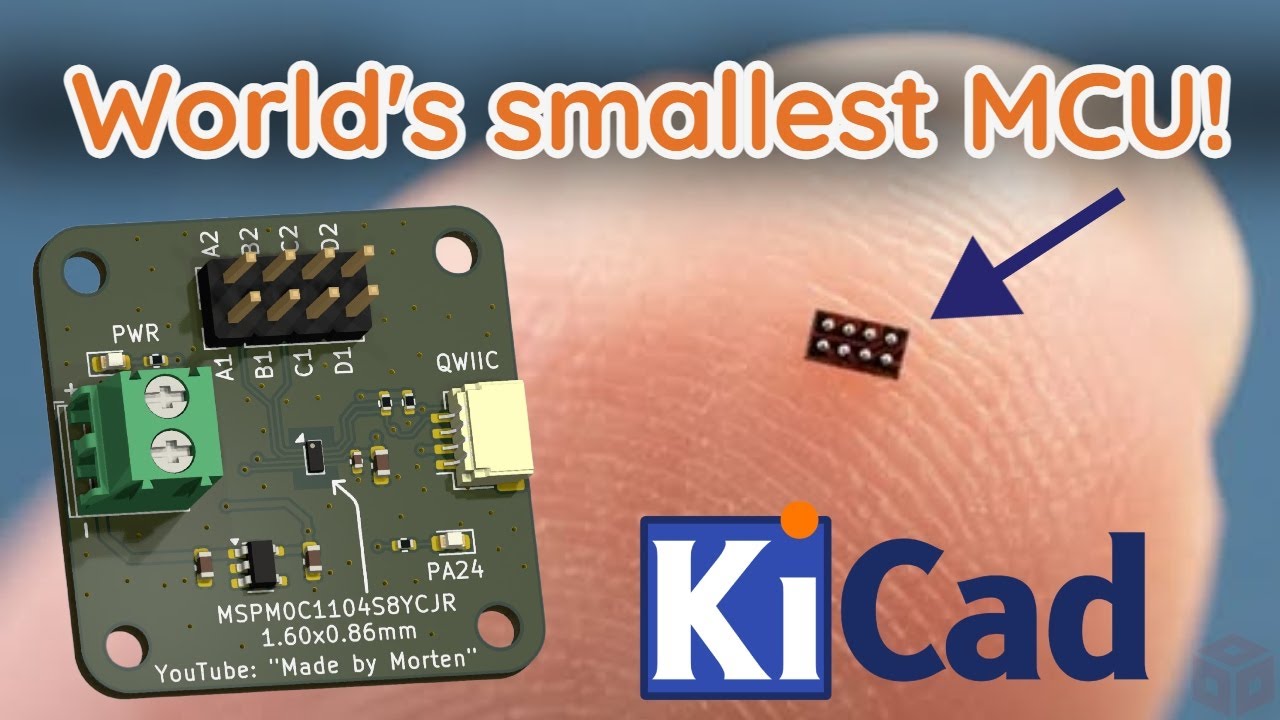
World's smallest MCU!
https://youtu.be/XSAPGh9um_k
In this video you will learn how to design with the smallest MCU in the world. You will see schematic and PCB design in KiCad 8, then you will see how you can solder this very tiny MCU to a custom demoboard.
You will also see some examples on how to download code and write your own. Some pratical demos will show some of the cool features from this amazing MCU.
The MSPM0C1104 is packaged in a wafer chip-scale package (WCSP) and measures only 1.60 x 0.86mm, a total of only 1.38mm2.
Belive it or not, but there are 8 pins under this package, spacing between these pins is only 0.35mm!!
Thanks PCBWay for sponsoring this video - https://pcbway.com/g/i8683S - Use this link for $5 new user free credit.
In this video you will learn how to design with the smallest MCU in the world. You will see schematic and PCB design in KiCad 8, then you will see how you can solder this very tiny MCU to a custom demoboard.
You will also see some ...
idle tinsel
sly rampart
Since <https://pinoutguide.com/HD/M.2_NGFF_connector_pinout.shtml#Key%20A+E> has...
Interesting, to say the least; but a totally different use case.
Do you know any motherboards with B-key M.2 that have full USB3 support?
idle tinsel
If you want a M.2 SDR, just wait a little bit (and bring some more than $100'ish cash).
https://www.crowdsupply.com/wavelet-lab/ssdr

Not my design, just to share ideas what is out there.
sly rampart
Yeah I saw that, something like that but accepting a longer form factor and not relying on any FPGAs so it's a bit cheaper the other way.
 west zinc

Severance is renowned for its distinctive production design, and we were tasked with bringing the WoeMeter to life—from early sketches to a fully func
Adafruit sighting on Severance props.
stark latch
west zinc
https://make3.co/work/woemeter
A friend of mine does a lot of scifi prop reproductions. Currently working on a woemeter: https://mastodon.social/@tankgrrl@hachyderm.io/114259777421628479
untold briar
Do projects have to be finished to share? 😂
I asked for help a while back with my LED PCB design and I just finished assembly on my second revision. They work perfectly!
sly rampart
Ooooh... building a light-up musical keyboard looking at the spacing and shapes?
untold briar
sly rampart
Ooooh... building a light-up musical keyboard looking at the spacing and shapes?
Yes this is actually my second version of it, I shared the first but it just used a strip
untold briar
https://github.com/jmauerhan/piano
This is the original one

GitHub
Audiovisual Piano Art using CircuitPython & Neopixels - jmauerhan/piano
 royal moon
I'm working on making a solar street light

This will be fun to test my solar math on
It has a charge controller, timer, light controller and a 12V 8Ah lifepo4 headway battery pack I made
dark cairn
eager stirrup
inquiring minds are curious if you plan on throwing this up on github or selling...
https://github.com/bill88t/m2s3
I'll make the repo fancy later, just added the stuff on it. The board works.

GitHub
A ESP32-S3 M.2 B-Key board that can be controlled over host USB. - bill88t/m2s3
dark cairn
idle tinsel
Awesome. This looks great. What host PC/SBC/motherboard are you using? Looking f...
The files are out, have fun!
I wanna eventually make a revision that support more m.2 keys and has better button pads, but that will take a while.
 shut kernel
Hi everyone!
We designed a FeatherWing for 10BASE-T1S.
What is that?
10BASE-T1S is a version of Ethernet that uses a single twisted pair of cables. It is a bit slow at 10Mbits, but it makes wiring super easy. The other cool feature is that it can do multi-drop. In the image you can see the board has two 2-wire terminals. You can daisy-chain these boards and each board will show up in your Ethernet network with it's own IP address.
10BASE-T1S was developed for automotive applications, but we think it can be useful for other things, too.
It has many of the same benefits of CAN, but on the logical side, it's Ethernet.
We have libraries for Arduino and Zephyr (not released yet, but if there is any interest we will release it under MIT).
We designed the boards for our own use, and I'm posting here with a simple question:
Would anyone be interested?

 twin musk
My studnets completed the first products of the semester in their "no prior knowledge required" Physical Computing course. The only directive was to "Make Art", with "Art" defined very losely. All used CircuitPython. Most used CircuitPlaygrond Bluefruit or Raspverry Pi Pico W boards. Here's a 3 min video of their work:
https://youtu.be/u-Jj8-GV404?si=SI76I_EZ2w2NPEm0
And their instructables are at:
http://bit.ly/make-art-2025

My students build three original projects in their CircuitPython-focused course: Physical Computing: Art, Robotics, and Tech for Good. This first project had a two word directive: "Make Art". And as you can see, "Art" is very broadly interpreted.
You can find student instructables here so you an rebuild any of these projects:
https://bit.ly/make...

Google Docs
Make Art Projects - Spring 2025 Thomas Alexander Project Name: Real Time Public Transit Tracking Map Description: The Real Time Public Transit Tracking map is designed to provide live train arrival data for Washington DC Metro users. This map was designed for a metro user who wanted a functiona...
dire axle
Recently bought a G3061 Hot Plate to help with SMD soldering, and decided to add a VL53L0X ToF sensor to automatically start and stop the heating when it detects a PCB. Redesigned the whole case in the process too
limber temple
 valid cedar
Ships Lantern art piece for my office: I used addressable LED rings from Adafruit and an Arduino UNO, leveraging the FastLED's fire simulation to get the flickering effect. I did need to use the cool/hot colors to get the right color output through the colored glass. A potentiometer controls brightness. The wood started out as 2x12's I cut to size, and routed out channels to hide the wiring. I dyed the cord for rope whipping with coffee.
dire axle
Here is the Printables link for the G3061 hot plate with PCB detection project with instructions: https://www.printables.com/model/1260791-g3061-pd65w-mini-hot-plate-with-pcb-detection


Printables.com
G3061 With PCB Detection | Download free 3D printable STL models
 slate torrent
I've been working on making a standalone ADS-B receiver that doesn't use a computer or SBC to decode the data.
For now I've only made the RF "demodulator". It uses an LNA to amplify the signal by about 35 dB, then passes it through a SAW filter that filters out most of the unwanted signals. A logarithmic power detector converts the signal to voltage pulses. ADS-B is modulated in simple RF pulses, so basically AM modulation with 100% modulation depth. Therefore a logarithmic power detector is a simple way to convert it to pulses that can easily be sliced in a decoder.
After a bit of testing I found that there were still quite a lot of unwanted signals, so I might need more filtering to completely get rid of it.
I based a lot of this on another project doing something similar, but instead of using a microcontroller with a configurable logic unit or an FPGA I want to do it in assembly on a fast microcontroller. Link to that project.


 stark latch
Upgraded my keypad from membrane to mechanical (mx "brown" key switches). Same Trinket MCU and Arduino code, just new keys and enclosure.
 idle tinsel
dark cairn
I wanna eventually make a revision that support more m.2 keys and has better but...
idle tinsel
dark cairn
I wanna eventually make a revision that support more m.2 keys and has better but...
Thanks for sharing.
The sad part of M.2 is that the A,E key pinout has the USB2 lines on different pins than the B,M key pinout. Boards could be made so much more universal.
 peak oriole
After years of thought and finally acting on them, I have come up with a bowling swing analyzer. There are 2 units mounted to the hand and arm. The arm unit is an Adafruit Feather Sense nRF52840 which connects to the hand unit which is an Adafruit BNO085. A lithium battery is in the arm unit. The connection is a 4 wire I2C.
Data is captured or transmitted live from the Feather Sense/BNO085 using BLE to a Raspberry Pi Zero 2 W. The RPI is mounted to a Hosyond 7" touchscreen which displays and controls what data is supplied (live vs data array) using Tkinter and matplotlib. Up to 100 swings can be stored. They can also be transmitted to a desktop/laptop in .csv format.
The Adafruit units are running CircuitPython code and the RPI is using Python3 under RedHat (RPI version) linux.
A prototype of the unit is in testing and the software is under development to add haptic feedback. Also waiting on another spool of filament to finish my 3D printing, hand case/ rear display panel.The results have been very good so far. The arm unit with the battery weighs around a couple of ounces. I printed out and designed most of the cases using a 3D printer. If you flip it to the outside of the arm it can be used with other sports but have yet to think about that. I can't say much more as I am working with a Provisional Patent.
@glad roost thanks for the incredible patience and help you gave me to finally realize my dream.
and thanks to @upbeat geyser for a ton of insights, mostly the RPI Zero 2 W and using spamazon as little as possible.

 stark latch
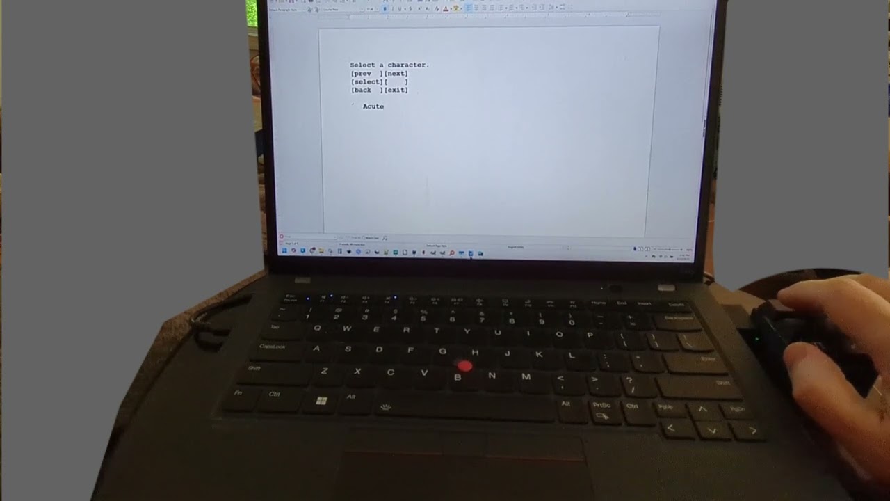
Trying something fun with keypad. The only hardware being used is a Trinket M0 and six MX keys.
Yesterday, I added the capability of remapping any key, with the option of saving the changes to flash memory (internal to the Trinket).
When you press the two middle keys simultaneously, it enters programming mode. It then types out instructions into whatever text editor you have open. I'm using LibreOffice here.
The video shows me remapping the ° key to type © instead.
https://www.youtube.com/watch?v=963mskZmItc


 tropic sparrow
Just looked that one up, hilarious
stark latch
Here's a demo of the keypad I made.
https://www.youtube.com/watch?v=YLER9jSqPbg

This is a 6-key keypad I put together using 6 MX key switches, and Adafruit Trinket M0, and a few parts I 3D printed.
Arduino source code is available at https://github.com/degroof/programmable-keypad
Source code is on github for anyone interested. https://github.com/degroof/programmable-keypad
limber temple
Bought so many panels. Time to start building the projects
Mostly 5+ year old projects at this point but IDC I'm geeking out
marble mantle
creating my own customized version of XRP robot, a 2-motor robot designed for educational purposes:


started a hackaday project documenting my progress:
https://hackaday.io/project/202865-customized-xrp-robot

My customizations of XRP robot from Experiential Robotics
limber temple

I dropped it and blasted off a few pixels but whatever. Now I have a "dry fitting" extra panel 🤣
limber temple
marble mantle
started a hackaday project documenting my progress:
https://hackaday.io/project...
I should do that. I've just replicated others projects but I did some slight c++ just to fix something that broke
errant pasture
Just barely missed show and tell today. Sorry y'all 😿
sand grotto
stark latch
Here's a demo of the keypad I made.
https://www.youtube.com/watch?v=YLER9jSqPbg
That's super cool 😎, I particularly like the interface via notepad/any-editor using key_sends to display a menu ⌨️
Presumably it uses backspace to clear previous menu or CTRL+A...
stark latch
sand grotto
That's super cool 😎, I particularly like the interface via notepad/any-editor u...
Yep. I have a clr() function that sends keystrokes to select the current line and hit Del, and a cls() one that selects the entire document and hits Del.
Still playing with it. Yesterday I added key repeat functionality.
 solar wadi
is it inspired by something ? I remember seeing some macropad many years ago that did something similar, using a text document to type the instructions I think, though I never used it and I don't know what it did exactly
I really like the way you did it
stark latch
solar wadi
is it inspired by something ? I remember seeing some macropad many years ago tha...
I've heard about a commercial product doing something similar but haven't seen it in action. I liked the idea of being able to edit the keys without the need for special software, so I came up with an implementation that worked for me. Currently (AFAIK) only works with Windows.
Might be fun to expand it to send multiple characters as well. The selection menus would get a lot more complicated, though.
solar wadi
ah there, I saved that bookmark in 2017 apparently but probably even earlier (it even uses a mini-usb). Actually the lackluster (and pricey) state of macropads at the time is partly what got me into microcontrollers
https://techkeys.us/products/sixkeyboard
sly rampart
At this point I'm usually making scriptable touchscreen panels that run off a microcontroller especially because Windows touchscreen handling is so atrocious.
I just wish I could figure out the last bits of the HDMI spec to generate a signal that the "HDMI only no DVI allowed" touchscreens that are so uber-cheap would accept, could just drop RP2350's on everything and call it a day.
stark latch
solar wadi
ah there, I saved that bookmark in 2017 apparently but probably even earlier (it...
Ah, yeah, that's the one. Odd that they don't have a demo video showing how to reprogram keys. I think this was the video where I heard the general concept of how it works. Still no demo of the programming method, though.
https://www.youtube.com/watch?v=AINgh4vF4VU
For this week's Show and Tell, Patrick stops by (our old office!) to share this custom keyboard set by TechKeys. The SixKeyBoard is a programmable keyboard with yep, just six keys. But instead of requiring desktop software, macros and shortcuts can be saved right to the keyboard to work on any system.
Shot by Joey Fameli and Edited by Norman C...
I'd be interested in seeing what their on-screen menus look like.
BTW, when I did a breakdown of my keypad, it came out to:
- 6 MX "brown" key switches: $7 (https://www.adafruit.com/product/4954)
- Trinket M0: $9 (https://www.adafruit.com/product/3500)
Everything else is 3D printed, so total cost is about $16 (assuming you have a spare USB cable).
stark latch
sly rampart
At this point I'm usually making scriptable touchscreen panels that run off a mi...
Now you've got me thinking about how to make a touchscreen macropad. 😆
An RP2040 Feather stacked on a 2.4" FeatherWing touchscreen would probably be sufficient. That's, what, about $50?
solar wadi
there are ESP32-S3 powered touch screens, which would be able to support a macropad over USB AND bluetooth seamlessly.
sly rampart
stark latch
Now you've got me thinking about how to make a touchscreen macropad. 😆
An RP204...
$40 of which is the touchscreen at that point. XD
solar wadi
like that for example: https://www.waveshare.com/esp32-s3-touch-lcd-3.5.htm (beware of the ones that don't have native USB connected to the USB plug like the Sunton panels that use a serial chip and have the USB pins on a separate jst plug - still usable with bluetooth, including ESP32 not-S ones)
ESP32-S3 3.5inch Capacitive Touch Display Development Board, 320×480 Pixels, IPS Panel, 262K Color, Onboard Camera Interface, Supports Wi-Fi and Bluetooth 5, ESP32 With Display | ESP32-S3-Touch-LCD-3.5
sly rampart
solar wadi
there are ESP32-S3 powered touch screens, which would be able to support a macro...
Yeah this is more a "the cheap HDMI touchscreens meant for AIDI64 are so TEMPTING" since the RP2350 can do more or less true HDMI now just... the difference between relying on "DVI fallback" mode and true HDMI is subtle and nefariously hard to get right. XD It's being able to handle a 1920x480 touchscreen that's only $50 and you have a direct framebuffer, versus juggling SPI rendering libraries and usually limited to only 480x320-ish.
 tight knoll
Finally got sound out of the thing after like a month. This is a drum machine/sampler based on todbot's macrosynthplug drum machine code.
I used Neotrellis because the lighting seemed cool. Seemed until I realised that the Neotrellis library cannot differentiate between a pressed and a held button..
the samples in the recording sounds horrible because it played the sound as long as the button registers as "pressed".
I'm looking to either write custom code or switch to normal buttons to make use of the adafruit_debounce library.
limber temple
tight knoll
Finally got sound out of the thing after like a month. This is a drum machine/sa...
Awesome man. I was thinking about buying a Kaoss pad or a drum machine this looks more fun
tight knoll
limber temple
Awesome man. I was thinking about buying a Kaoss pad or a drum machine this lo...
Im still experimenting with the pads section. will keep this channel updated with how I moved ahead :/ For now likely I'll go with the silicone pcb buttons for lesser sounds compared to the cliclky buttons on the PO-33
limber temple
limber temple
Now that I've gotten this repo to work, I want to try and code a breakout clone
But I've only worked with C sharp which was a lot more powerful than C++
I shouldn't say more powerful but it had pre-written classes
I tried it back then but I couldn't get the collision detection right
half marten
My top-changeable pillar project

Learn more: https://www.crowdsupply.com/axiometa/genesis-iot-discovery-lab
This pillar system is based on Seeed Studio’s ESP32-S3 development board and features the custom AX22 port I designed during the creation of GENESIS – a plug-and-play electronics lab for makers.
Supports 50+ modules including sensors, LEDs, switches, I2C displays, a...
 wise island
I'd been wanting to do something with LED filaments that I had, so I made some 7 segment displays using them and a carrier board to create a clock... Like me, it looks better in the dark 😉
 sly rampart
That looks AWESOME as it is, honestly!
Maybe sticking a small square ridge on the inside of each loop of the 8's so there's less cross-glow between filaments so the 'dark' filaments are darker, or maybe recess them a smidge in a groove you can paint with silver paint to really maximize the 'forward' glow.
wise island
sly rampart
That looks AWESOME as it is, honestly!
Maybe sticking a small square ridge on t...
Thanks! The filaments are recessed in the pcb. The vertical ones are solder on the bottom of the pcb and the horizontal ones are on the top. I did get 1mm instead of 1.6mm, so maybe the thicker pcb would be better?
 sly rampart
Yeah with that design just adding a small ridge on the inside edge of each loop of the 8 would likely be the easiest tweak, and quick to print a single square to test-fit and see how much it'd help.
There's no good words to feel I described what I mean well, ten-second redline it is.

Didn't realize the panels were actual PCBs, they looked like 3D printed spacers on the first photos, incredibly clean PCB designs, well done.
limber temple
Those extruded rods are pretty cool, but they're kind of a pain to work with. These are those magnet feet from Adafruit and I spaced out a little but I still need a little more to get flush with the frame but my screws aren't long enough

 supple mortar
Got a noice usecase for AdafruitIO. I run a python script on my vps to push the load and memory stats to adafruit IO. Then on my Tronbyt/Tidbyt device i plot out the values for a nice little server watch screen.

 twilit basin
supple mortar
Got a noice usecase for AdafruitIO. I run a python script on my vps to push the...
twilit basin
supple mortar
Got a noice usecase for AdafruitIO. I run a python script on my vps to push the...
That's a neat idea. I'm constantly checking nvtop but having a display would be handy
supple mortar
twilit basin
That's a neat idea. I'm constantly checking nvtop but having a display would be ...
Thanks. And pair the script with ntfy to have high load alerts
limber temple
supple mortar
I have yet to mess with the IO stuff but it's really cool
Just a teaser until I power it up...

Serpentine cables with one extra long one I had to order. But now I can mount the Pi under it
Used steel to connect them but there are cheaper ways to the frame


And that's the whole kit & caboodle. 50W for panels, Pi5 with its 25W adapter. 75watt machine
limber temple
It'll be the best thing to look forward to on hold'em night if you lose first 🤣
supple mortar
that's a lot of LEDS
limber temple
16,384 to be exact
It's not a surprise it takes some serious data flow to drive them
No HDMI encapsulation or anything to compress
I've seen them being used in the backs of old pinball machines to revive the display though. Pretty genius idea.
limber temple
supple mortar
that's a lot of LEDS
My biggest was 256x128 but I can't drive it that well. Too many for a pi, you would need the actual staging equipment from a site that makes them
sly rampart
I feel like it's one of the few times when a microcontroller would handle driving them better than the mainstream Pis since it's a lot of data to keep consistently pushing at high rates and it's not as visually forgiving to timing bumps as neopixels or the like.
Can't QUITE do it with HSTX on an RP2350 but the PIOs on that (or an RP2040) could both do it pretty well I'd imagine.
We're gonna see a lot more 'picovision' like RP2040/RP2350-as-faux-GPU solutions in the future I'd imagine.
limber temple
sly rampart
I feel like it's one of the few times when a microcontroller would handle drivin...
I definitely agree but my whole thing when getting into this was I wanted to have the machine that's running the game logic to be the same machine that's driving the panels. Therefore deleting thing in between.... I'm a big controller lag guy with retro games
I have a retrotink which is the fastest solution next to a Mr. Fpga or one of analog's consoles
sly rampart
Yeah but as you've found out the 'thing in between' was a LOT more capable of the protocol management than the source, sadly. XD
 topaz cipher
I just finished a project writeup for my 3D-printable PyBadge case: https://www.hackster.io/rhammell/pybadge-protective-case-with-d-pad-95c8a2

Hackster.io
3D-printable case for the Adafruit PyBadge that includes cushioned d-pad and button inputs By Bob Hammell.
I really like using the PyBadge, so this was my attempt at making a custom case for it. Design features include:
- D-pad Button: A raised d-pad allows for better thumb interaction with the board's four directional input buttons
- Compact Size: Case size is optimized to tightly enclose the board and battery/speaker, with minimal wall thickness to reduce its size
- Cushioned Buttons: Printed soft spacers are placed below each printed button for a softer, tactile press and reduced clicking noise
- Reduced Button Play: Tight print tolerances in the button openings and spacer gaps reduce button wiggle for a more solid feel
- Easy Install: The two case halves fit around the PyBadge board, fastened together using M3 screws to secure it in place
- Custom Colors: Case components (front, back, buttons) can be printed in various colors to create a customized appearance
 stark latch
limber temple
Houston we have a problem 😆
stark latch
limber temple
Houston we have a problem 😆
Playing Tetris with Extra Hard Mode turned on I see.
limber temple
stark latch
Playing Tetris with Extra Hard Mode turned on I see.
I fixed it, Just had to reverse the direction of the cables
limber temple
Or provide the orientation argument
But if I run it to the bottom panel first I can mount the pi lower
 sly rampart
So since @upbeat geyser stuck the idea in my head I tried a bunch of different orientations of the chassis and sensor and DID find one finally that the cable just reached and didn't cover up any status LEDs so I could use a stock off-the-shelf FPC cable.
It's nothing 'fancy' since it's all off the shelf parts in a carefully arranged stack but it's nice having a tiny brick of a self-contained decent DSLR that has around 8-12 hours runtime on a charge depending on how much the screen is on and that I have full control over and can do a whole lot with and surprisingly comfortable in the hand.


 lofty heath
Sharing for Feedback: Unhidra Sentinel™ — Local-Only Smart Security Node
🧠 Patent-pending concept now live
Hey folks — I wanted to share a project I've been developing that may interest the embedded and maker crowd. It’s called Unhidra Sentinel™, a context-aware security and accessibility device designed to detect "environmental drift" — changes in temperature, light, or ambient sound — and activate only when something meaningful changes. Think silent watchdog, tuned to subtle signals.
It's privacy-focused, offline-first, and designed with modular sensors in mind.
🖥️ Here's the prototype pitch site:
https://unhidrasentinel.netlify.app (mobile friendly)
I just filed the provisional utility patent and would love to collect some early feedback from the Adafruit community before I move deeper into firmware and enclosure prototyping. Thanks for the inspiration and the space to share!

 untold sable
lofty heath
Sharing for Feedback: Unhidra Sentinel™ — Local-Only Smart Security Node
🧠 Pate...
untold sable
lofty heath
Sharing for Feedback: Unhidra Sentinel™ — Local-Only Smart Security Node
🧠 Pate...
I am not really reading anything here that says patentable. What is it about your thing that is "non obvious" because everything you mention monitoring are basically the meat & potatoes for companies like Adafruit, SparkFun, etc. Why should your device get a patent?
untold sable
lofty heath
p.s. and I am not trying to be a jerk or anything. I am genuinely curious what it is that sets your device apart.
lofty heath
untold sable
p.s. and I am not trying to be a jerk or anything. I am genuinely curious what i...
Not at all friend! These are the questions I'd love to dig into.
Unhidra Sentinel introduces context-aware, privacy-first anomaly detection that operates completely offline. It doesn’t just sense — it correlates shifts across multiple domains (light + sound + temp) using onboard logic to determine when to activate.
The novelty lies in:
Multi-signal environmental drift detection

Event-based wake logic that avoids constant monitoring

Offline, non-cloud, no-training-required intelligence for secure edge use

A specific implementation flow combining those parts, which I believe crosses into non-obvious territory for passive-alert systems
I'd love to hear your thoughts — if it sounds obvious, I'm open to hearing why and pushing it further. This kind of back-and-forth only sharpens the work.
cedar trellis
lofty heath
Sharing for Feedback: Unhidra Sentinel™ — Local-Only Smart Security Node
🧠 Pate...
Coming to an open source community to get feedback about a patent. Sounds legit.
lofty heath
I get where you're coming from.
The core firmware isn’t open source yet, but I came here because the engineering feedback from this community is genuinely valuable. I’m building for resilience, privacy, and edge intelligence — goals I know a lot of folks here care about too.
If and when the project gains traction, I’d love to support a delayed open release model: giving early commercial partners room to breathe while still committing to community transparency down the line.
Appreciate the eyes and the honesty.
Understand your skepticism as well
grave nacelle
Posted a new playground guide about making hot-swappable memory cards for Fruit Jam (or whatever other board you might want): I2C FRAM Memory Carts

a few more photos of the memory card build


 sacred timber
lofty heath
Unhidra Sentinel introduces context-aware, privacy-first anomaly detection that ...
sacred timber
lofty heath
Unhidra Sentinel introduces context-aware, privacy-first anomaly detection that ...
I’d have to agree with earlier comments. Remove the fancy language around what this does (those four bullet points are full of buzz words) and there’s many decades of prior art.
If you can fool the patent office with the language, go for it, but I likewise don’t see a demonstrably unique invention here. And I’ve been around the block a time or two as regards patent law, though I am not a lawyer.
lofty heath
sacred timber
I’d have to agree with earlier comments. Remove the fancy language around what t...
That's fair criticism, but let me offer this.
This is a concept prototype
There's no logic to back this up
The board arrives today, and I start building the firmware
And I'm not looking to fool anyone brother, I'm looking to add value to an industry full of spyware that devalues privacy
sacred timber
Well, my advice would be that if you believe you have a viable product go for it, develop and sell it. But I frankly wouldn’t attempt to obtain a patent. It’s very costly just to hire a lawyer to do the prior art investigation, and based on your description you wouldn’t get remotely near a defendable patent.
lofty heath
While I appreciate the advice, understand that it comes off as dismissive
That's not constructive, it's discouraging
I'm not trying to win a legal battle, I'm building momentum
sacred timber
I’m merely trying to be very frank based on your product description. You can’t obtain a patent through marketing language. You have to have a real innovation. As I said, there are decades of similar patents already. Think of it this way: prior to the cloud all security systems were “offline” and used multiple sensors and operated in a way that only triggered an alarm or external message when specific environmental factors were changed. That’s how most security systems worked.
sacred timber
lofty heath
I'm not trying to win a legal battle, I'm building momentum
To obtain a patent you actually do have to win a legal battle.
lofty heath
I'm not trying to patent a finalized invention, I'm prototyping. You're undermining the the collaborative and nurturing vibe that spaces like adafruit are supposed to embody. Your "frankness" isn't helpful when it ignores context and talks over my intent
I appreciate the insight, but I think we're operating from different assumptions
This is how ideas get refined, not litigated
Even when things are raw or ambitious
sacred timber
I’m undermining? If you only want encouragement don’t ask for advice. Reality is reality, if you don’t want frank, real advice then make clear what you want.
lofty heath
I'm not here to prove originality to the USPTO, but to build something meaningful and privacy-conscious alongside other who care. If that's not welcome here, I understand.
But I believe there's still room for projects that challenge the status quo
Limor fried built adafruit to protect and empower outsiders, not reinforce gatekeeping
sacred timber
For example, I served as an expert witness supporting a case held by a UN initiative against XML related patent claims by Microsoft. It was relatively easy based on my background to locate the prior art and win the case. Patents require a demonstrable innovation. If you can prove you have that you can obtain a patent.
And by the way, trying to turn my comments around as not being sufficiently supportive of your endeavour is bogus.
You’re claiming I’m gatekeeping and you deserve empowerment and that you’re an outsider and that you’re somehow challenging the status quo?
Enough. Enjoy your project, I have nothing further to add.
lofty heath
I respect your credentials, I conceived this idea in the hospital three days ago while on my deathbed after a seizure with nothing but a chromebook and a pair of tweezers and a screw driver.
I'm not here to impress microsoft, I'm here to build tools to protect people like me
Outsiders, fighters, survivors
In a world that devalues privacy and punishes vulnerability
If that's not innovation worth defending, I don't know what is
I get it, I'm not everyone's cup of tea, I'm relentless and I don't sugarcoat what I believe in. If that's too much, that's okay. This work is not for the timid
sly rampart
grave nacelle
Posted a new playground guide about making hot-swappable memory cards for Fruit ...
I know this got lost in the buzzword bingo that followed, but this is a really neat demo of the FRAM stuff that isn't talked about much but can be super handy sometimes to stuff a little 'configuration space' for permanent settings into a project easily.
Honestly those 3D printed case files are gold to have around for making connector-based projects and really takes advantage of the extra pins on the ends of the small-tin perma-protos that are ideal for those sorts of connectors.
I'd probably do the extra wiring steps to move the VCC/GND to opposite-end pins if I built that, but that's a very clean and reproducable build to keep things layed out nicely.
untold sable
lofty heath
I get it, I'm not everyone's cup of tea, I'm relentless and I don't sugarcoat wh...
You don't sugarcoat what you believe in but then get upset when people don't sugarcoat their doubts about your project being patentable? Feedback, I guess, is not for the timid. I was the original reply to your post last night casting doubt on this but didn't log back on until today and Ichiro basically said much of what I was thinking. I also saw lots of buzzwords in what appeared to be mostly a marketing of an idea.
As to this forum being supportive, if you have specific hardware and software concepts you would like feedback on, we are all very happy to lend an opinion or suggest a direction. But we are warning you that much of what you are talking about is not new or innovative to the point of receiving a Patent. And many times people use a buzz word to imply something but then the reality is the hw/sw version of that function is not at all what the buzzword really means. Case & point, about 99% or more of everything called "AI" is not AI.
That said it still might make a good commercial product all the same. Those two things, patent vs commercial product, are mutually exclusive as many projects are selling well known functions/ideas and many patents are not easily commercialized. But since this community is largely about open source and often hobbyist one off projects where some might come here to find inspiration in projects shared here, you will have to forgive us if your post came off more as an advertisement, especially now that we know you don't actually have any HW nor SW yet but nothing more than a one page marketing concept, rather than showing a working prototype that might inspire others here.
lofty heath
untold sable
You don't sugarcoat what you believe in but then get upset when people don't sug...
100% valid points
I did start this project about 47 hours ago, the esp board will be here soon and I'll get to work.
And I don't mean to seem combative, but if it gives any context I am literally living on borrowed time
I want to do this right and serve this community the best I can
Everyone I've ever met has tried to shut the gates on me, and I'm not about to go down quiet
I come from sales and marketing so that's just where I started, I'll build it out and make everyone here proud before time's up
Not trying to be dramatic or gain sympathy, I don't want that. I'm just trying to make it make sense where I'm coming from
I'd rather go out with a blood curdling screech that ruffled feathers than a whimper
And look who just just showed up

commit: ignite/esp32_arrival
msg: The weasel has teeth
lofty heath
 lofty heath
First successful test 💜
lofty heath
 lofty heath

 lofty heath
bitter dome
lofty heath
lofty heath
bitter dome
lofty heath
the overworld theme makes everything funnier to watch
cedar trellis
lofty heath
Happy for you that you're building your first electronics project. However, the show&tell channel is not meant to be used as a personal build log.
Feel free to document your progress in a personal blog and share the finished product with the community. If you need help, ask specific questions in the help-with- channels.
But this is just clutter and spam.
lofty heath
bitter dome
the overworld theme makes everything funnier to watch
Right?
lofty heath
cedar trellis
Happy for you that you're building your first electronics project. However, the ...
Wouldn't call it spam, but sure. I'll kick rocks
sly rampart
Yeah kinda like trying to attach the really small DPI screens that plug into the GPIO headers always is a balancing act to get them to plug in without cracking the screen. >_>
sacred timber
Another small step for robots... here's an open loop square by the KRZ03 using a simple macro processor that reads a text file and performs the steps it contains. Nothing fancy, not actually a square (no closed loop motor control) but it has flashing lights and sound fx...
https://youtu.be/6wSN5q6eZvk
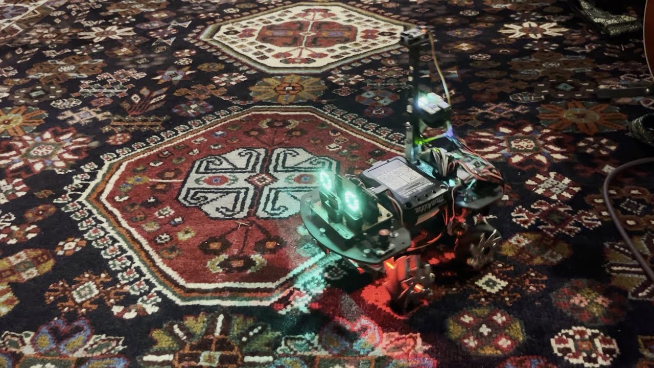
I've written a quick and dirty macro processor where I can specify a text file containing motor control commands, and this demo has the KRZ03 navigating a square, i.e., moving forward, rotating and doing that a few more times. There's no magnetometer to align with a compass heading, this is all just done using time delays, very simple.
Obvious...
 lapis jasper
lofty heath
Wouldn't call it spam, but sure. I'll kick rocks
lapis jasper
lofty heath
Wouldn't call it spam, but sure. I'll kick rocks
I think #help-with-projects and maybe a thread would be a better place. #show-and-tell is usually lower volume with links or pictures to projects
stark latch
I built a little box to monitor battery drain for microcontroller projects. If I know the current draw, I can figure out the size of LiPo battery I need. In this example, it's pulling 278mA, so a 500mAh battery would last about 2 hours on a charge.
The box just contains a JST cable, 2 banana plugs and a toggle switch. When the switch is in the down position, current flows through the multimeter. In the up position, the meter is bypassed. Nothing really fancy, but it beats messing around with alligator clips (or worse, J-clips 😱 ).
Bonus feature: When the microcontroller is plugged in to a USB port, the meter shows charging current.

 north mural
Upgraded my electronics workbench this past month. Yes it's wood working but ultimately to make electronic parts more organized with more storage. Used a french cleat system to hang akro mills parts organizers. Wall mounted dual 1440p monitors.


Now have the 12 panel matrix array on the shelf. This is probably as far as it goes. Unfortunately something happened and I can't pay the bills and will likely lose my house in the coming months. Next owners will get a very nice workbench. This will likely be the last major project update here. It's been a nice couple of years here and this community is one of the best I've ever been a part of online.
exotic sierra
north mural
Now have the 12 panel matrix array on the shelf. This is probably as far as it ...
Sorry to hear your predicament 😦
sand grotto
north mural
Lovely looking space! What wood is the darker stained panelling?
Also sad to hear it may not be yours much longer, fingers crossed for an unexpected solution
limber temple
I would offer to buy panels but I'm like 30 deep
north mural
sand grotto
Lovely looking space! What wood is the darker stained panelling?
Also sad to hea...
It's just sheets of stained and urethaned plywood. It's darker because I used 2 coats of stain and the desktop only has 1 stain coat. There are vertical and horizontal studs behind the plywood spaced specifically for mounting the french cleats and metal cabinets. Didn't even get a chance to add the drawers on. Because the plywood has a urethane coating it's a breeze to clean sawdust from them, just a hand brush and the dusty plywood looks glossy again.

 fervent estuary
Although I have bought and dabbled with numerous Adafruit stuff, I am pleased to show my very first "completed" project. A 128x64 pixel message board using Circuit Python on the matrixportal S3. I used the Adafruit Messageboard https://learn.adafruit.com/matrixportal-circuitpython-animated-message-board instructions. Thank you Melissa! Learned how to modify the cad files in Fusion 360 to move the mounting for 2270 matrix holes and made my first 3d prints. Moved the controller to the end. Now using at fundraising events for my Vex IQ team going to World Championship.


LED matrix animation using bitmaptools and the MatrixPortal S3
 rough dew
Finally finished my website! I'll refine it over time, but it's a pretty big milestone to just... have everything up. Made with Vue & packed with Vite. Served on github pages!
 exotic sierra
rough dew
Finally finished my website! I'll refine it over time, but it's a pretty big mil...
exotic sierra
rough dew
Finally finished my website! I'll refine it over time, but it's a pretty big mil...
I host a static website on cloudflare’s free plan. https://oakdev.tech
I want to eventually add some blogging functionality to it so I can document personal projects. Currently it’s an old placeholder for my old hobby business. It would be a fun exercise in content hosting/delivery.
errant pasture
Y'all dig my graduation cap? RP2350 with two GC9A01A screens, an IMU, and a modified version of @median spoke 's googly eyes script. 👨🎓
 rough dew
I was really tempted to do the same after getting my Solutions Architect AWS cert, but... the level of complexity to do it right just felt unnecessary
exotic sierra
rough dew
I was *really* tempted to do the same after getting my Solutions Architect AWS c...
I absolutely understand the sentiment. I played around with making a TikTok clone web app by setting up a CDN on AWS and fetch content. It was fun but the mental overhead to keep it up and whatnot was a bit much for me.
Also lots of the things for CDN aren’t covered under the free tier so that was a small bummer.
rough dew
errant pasture
Y'all dig my graduation cap? RP2350 with two GC9A01A screens, an IMU, and a modi...
Also this is super cool, love the themed wire colors & clean bends
 median spoke
errant pasture
Y'all dig my graduation cap? RP2350 with two GC9A01A screens, an IMU, and a modi...
median spoke
errant pasture
Y'all dig my graduation cap? RP2350 with two GC9A01A screens, an IMU, and a modi...
Never tried it on a RP2350 the floating point would help a lot
errant pasture
median spoke
Never tried it on a RP2350 the floating point would help a lot
Performance isn't exactly as good as I would hope, but I didn't really have time to diagnose it.
median spoke
errant pasture
Performance isn't exactly as good as I would hope, but I didn't really have time...
That may actually be displayio logic too
limber temple
limber temple
Not from ada but it's the best acrylic I've found for this pico project. Is called chemcast 60% light transmission. I ordered it from tap plastics but it was pricey
marble mantle
finally released a new version of my logic bits kit - for demonstrating logic gates to students (and not only)
https://www.tindie.com/products/irobotics/logicbits/

now includes an s-r latch
 sacred timber
marble mantle
finally released a new version of my logic bits kit - for demonstrating logic ...
sacred timber
marble mantle
finally released a new version of my logic bits kit - for demonstrating logic ...
Very cool! Are you using TTL or CMOS gates for this or discrete components?
marble mantle
cmos
SN74LVC seeies
sacred timber
marble mantle
cmos
SN74LVC seeies
Very classic! Strangely, I think I can remember the pinout for some of those in my head after more than four decades. 😲
marble mantle
 sacred timber
marble mantle
sacred timber
marble mantle
Nice clean design. I'm sure that's very helpful in the classroom.
rough dew
errant pasture
Performance isn't exactly as good as I would hope, but I didn't really have time...
super late to the party here, but I've found that some adafruit display libraries REALLY need tweaking for the best speed. One OLED display library (can't remember which) was re-drawing the entire display over i2c for every new pixel. It made drawing squares nightmarishly slow. Turns out there was sorta code to batch the requests, but it wasn't fully implemented. Filling that out made my displays go from 2fps to 40
errant pasture
rough dew
super late to the party here, but I've found that some adafruit display librarie...
I was getting more around 6-8 fps (just visually). @sharp comet is the displayio wizard here, so he might have some more insight on this.
sharp comet
Displayio itself can slow things down some. For squeezing out the most performance I think it's possible to interact with the bus directly skipping displayio like gifio can do I believe. AFAIK though SPI bus displays will always be faster than I2C, so if you really need fastest refresh possible it can be worth using a SPI display instead.
Within displayio it depends a lot on how much stuff gets updated on a given frame, if only a small region of the display is updated such as changing a single or a few small glyph from one character to another, or moving a small sprite a little bit then the refresh is fast enough to get decent FPS. However if you need to redraw larger portions or the entire scene then it can slow down considerably.
rough dew
sharp comet
Displayio itself can slow things down some. For squeezing out the most performan...
I remembered wrong, I was using SPI! In my case it was drivers for the SSD1309. I made two local changes to the adafruit libs:
- monochrome display libs used a buffer where each byte represents 8 pixels. Updates are sent to the display 1 byte (8 pixels) at a time. There seemingly wasn't any batching here, so changing 8 pixels, even in the same byte, resulted in 8 separate display updates.
- the
display()function allowed me to make multiple "canvas" edits before updating the display, but it still updated the WHOLE display no matter how few edits I made. Implementing a second display buffer ate a lot of ram, but it allowed me to compare differences & only update what changed.
I also vaguely remember that there wasn't any "software" drawing? memory's fuzzy on that. I might revisit this & try to make some actually-good contrib's to the adafruit git repo for it.
clever stone
Finished up the CircuitPython code (with deep sleep) for my Bluetooth Presentation Clicker and designed a snap-fit case (will likely change the colors). The finished case is 53mm*20mm.
Shout out to @glad roost for helping debug the CircuitPython and for spinning a PR for something we uncovered.
I'll use this for my DCNextGen workshops.
(DCNextGen is a youth track at the DEFCON conference in August each year).
It may be nothing but I hope using a functional tool - built with CircuitPython - might inspire a young hacker.
After the conference, I will likely repurpose the Circuit Playground Express Bluefruit. It's just so feature rich and very useful hardware!
clever stone
I did a little ergonomic testing of the CircuitPython Presentation Clicker and wanted to taper and smooth out the edges a bit.
The bottom has more taper to improve how it settles on my hand. (it's a balancing act between curved edges and printability)
size = 53mm*20mm w/ 950mAh LiPo
 grave nacelle
Just posted a work in progress project update video for the Fruit Jam gamepad tester project that I've been working on. Goal is to read buttons and dpad from XInput, Switch Pro compatible, and generic HID gamepads, then display the button state in a sprite based visualizer on the DVI output. First two are easy-ish as the button layout is standard. Generic HID gamepads are tricky though because the layouts vary from device to device. youtube link: In progress -- Fruit Jam Gamepad Tester

Work in progress on my gamepad tester for Fruit Jam with RP2350 and DVI output.
Currently I'm in the middle of doing a bunch of HID Report descriptor parsing to make sense of control mappings for generic HID gamepads. XInput button polling already works fine, but I'd like to add support for both Nintendo Switch Pro compatible gamepads and gener...
wide brook
rough dew
Finally finished my website! I'll refine it over time, but it's a pretty big mil...
Congratulations! However, please please please change your CSS so that all text is clearly distinguishable from the background.. As it is, people with vision deficiencies may have trouble making out some of the text. For more information, check here: https://www.w3.org/WAI/WCAG21/Understanding/contrast-minimum
If you want to quickly evaluate candidate color pairs for their suitability, this website provides an easy-to-use calculator: https://webaim.org/resources/contrastchecker/
Thank you in advance for your consideration!
sly rampart
wide brook
Congratulations! However, please please please change your CSS so that all text ...
The screenshot got resized down which messed with the contrast because the resize wasn't gamma/contrast-aware and appears to have been a simple linear resize so it's got some moire-like effects on the text.
If you check the actual website (it's in that users profile) it's #000000 text on #FFFFFF background, literally the best possible for a 'light' theme.
rough dew
sly rampart
The screenshot got resized down which messed with the contrast because the resiz...
True, but the main title/subtitle and tabs are most def failing contrast accessibility checks. My primary font being so light (thin) doesn’t help either :x
for example, this text fails contrast even if it's on a white background

It'll take me a while to keep the same aesthetic & still past contrast, but it's a strong priority.
sly rampart
You'd need to mess with the CSS more extensively than I did for this quick test, but the age-old trick of a "text-shadow: 0 0 1px $COLOR" can work good on headings with larger text to goose contrast.
You'd need to change the H1 to stop having pure-white plus near-black in the same heading to avoid that color fringe my screenshot has or get fancy with custom-tailoring the 'fringe' color, but it gives the general idea.
 wide brook
If you decide to go with an outline, you'll have to make it considerably larger than 1 px (consider actually using font size-relative units for this, like em/rem so that the outline properly carries over if the user has specified a font size override) to be perceptible, and you will still have to ensure that it contrasts well with both the text and the background
Also please note that the text on the bottom of the header ("Or" and "depending on the mood") also fails the contrast check
clever stone
I discovered the Circuit Playground Bluefruit doesn't have LiPo charging (while it does have a JST for a LiPo).
I fixed that. 😉
This could be the first Adafruit Circuit Playground Bluefruit with build-in LiPo charging!
I am not completely happy with the location of the yellow LED (charge indicator). I may move it.
 clever stone
the BLE Presentation Clicker
It's an @rustic stag Circuit Playground Bluefruit (with a few mods including smaller JST connector, LiPi, and LiPo charging).
I settled on a 3D printed case and buttons with an acrylic faceplate.
Active power usage is just 2mA ... impressing for #CircuitPython 👍🏼
addendum:
Q: Why create a Bluetooth presentation clicker vs buy one?
A1: This runs CircuitPython so it is easily customizable
A2: This is a "teachable moment" when I use it for presentations with youth ... like at DEFCON with the DCNextGen workshops
A3: I learned a lot while creating it
A4: It looks cool
clever stone
Automated battery drain test 💪🏼
3D printed PCB Probe Jig +
RPi4 running Python script +
OWON Python API +
Adafruit IO
- I am using my PCB Probe Jig to measure the battery voltage with the OWON HDS272S (red and black probes).
- The RPi4 is running a python script to read the OWON and send data to Adafruit IO.
- The RPi4 is also using GPIO to trigger the button events on the PCB via the Probe Jig (white probes).
 lucid bloom
I made an analog phone system for my friends computer museum. Been playing with it this week, I got all kinds of things working. I can ring any phone from home assistant, I can send webhooks from extensions with asterisk and I made a dial an adventure game. Today I did eth0/wlan0 forwarding so I can plug the ata into the pi running asterisk. It's an 8 port version and it's gonna get filled up with at least 1 payphone.
 topaz cipher
I built a game - Face Invaders - for the Adafruit PyBadge! The gameplay is just like asteroids, but for fun, the asteroids are replaced with personalized face sprites. So you can dodge and shoot floating heads of your friends, family, or yourself!
This was a fun learning project on the PyBadge. Lots of work went into getting the game to run smoothly on the PyBadge hardware, and I even ended up making a contribution to the CircuitPython project to include some audio playback features used in the game.
Here is a build tutorial on Hackster.io: https://www.hackster.io/rhammell/pybadge-face-invaders-c26c30


Hackster.io
An asteroids-like arcade game that runs on the PyBadge and features personalized faces to dodge and destroy By Bob Hammell.
 uncut swallow
My "morning" project ended-up taking most of the day: Adafruit Capacitive Soil Sensor connected to a Unexpected Maker Feather S3 sending data to AIO, inside a 3d printed enclosure. (With CircuitPython)


 sacred timber
uncut swallow
My "morning" project ended-up taking most of the day: Adafruit Capacitive Soil S...
sacred timber
uncut swallow
My "morning" project ended-up taking most of the day: Adafruit Capacitive Soil S...
Cool, so are you using ESP32-Now or -mesh? And sorry, what is AIO?
uncut swallow
sacred timber
Cool, so are you using ESP32-Now or -mesh? And sorry, what is AIO?
Adafruit IO
sacred timber
uncut swallow
Adafruit IO
So rather than say a local Grafana instance (or whatever) you're sending it off to Adafruit's web service for $99 per year. I see there's also a free account option. (I'd not heard of AIO before)
uncut swallow
sacred timber
So rather than say a local Grafana instance (or whatever) you're sending it off ...
Yes. I’d rather focus on making the thing to get the data than display it.
sacred timber
uncut swallow
Yes. I’d rather focus on making the thing to get the data than display it.
Agreed. We all have different interests and priorities, and they can change by the hour. Some people really like doing visualisations (myself I use D3 normally), but I also go back and forth between hardware and software. Some days I just to be cutting and sanding or soldering something rather than staring at a screen...
clever stone
uncut swallow
Adafruit IO
I just started using Adafruit IO. I'm using it for performance testing data. I need data collection and a few simple graphs. It takes just seconds to get what I need.
 untold sable
sacred timber
So rather than say a local Grafana instance (or whatever) you're sending it off ...
untold sable
sacred timber
So rather than say a local Grafana instance (or whatever) you're sending it off ...
Give the free version a try. After all, it is free!
stark latch
I'm working on a design for a custom mouse/trackball, so I built a test bed to verify I could get all the bits and pieces working together. As it sits, it functions as a (somewhat boxy) USB optical mouse with 3 buttons and a scroll wheel.
The hardware consists of:
- a PMW3610 breakout board ($30)
- three 6mm tactile switches ($0.40)
- a scroll wheel encoder ($1.50)
- an RP2040 Feather ($12)
Everything else is either wiring or 3D-printed parts.
Next step is to build a trackball testbed using the same optical sensor.

Here's a (slightly shaky) video of it in action. https://www.youtube.com/watch?v=s2dFzdyvv38

I'm working on a design for a custom mouse/trackball, so I built a test bed to verify I could get all the bits and pieces working together. As it sits, it functions as a (somewhat boxy) USB optical mouse with 3 buttons and a scroll wheel.
The hardware consists of:
- a PMW3610 breakout board ($30)
- three 6mm tactile switches ($0.40)
- a scroll...
 nimble sapphire
LAtest 3d print :

 weary cloud
DIY bootleg neuroscience device to alter perception of reality.
We don't see reality as it is. Instead, we pull meaning extrapolated from raw sensory signals into multiple conceptual symbols, meshed from biological to conceptual, forming the "sense" of the world. Perceptual manifold concept kinda covers this interplay as a high level summary of studies into neuroscience/biology and so on.
Much like language allows us "perception" into conceptual landscapes, not paying attention to the constituents of the words themselves vs what the symbols refer to... so also do our senses of the world external form in similar ways. Depth perception is combined and extrapolated from bifocal vision, movement through space, hearing etc. Wetness comes from pressure, texture, temperature. Balance, time, more and more. All constructed senses.
So encoding new patterns via tech injects new "symbols".
Custom LRA driver PCBs as a first attempt at making them, but really could drive most of what this does with off the shelf parts sub $50 sans the specific sensors. (especially if not building like this was built vs full wristband print in TPU).
Currently daily run mlx90640s and vl53l5cx on both wrists (have smaller 8x haptic band on other wrist).
Different sensors give new lenses to info indirectly-lots of interesting info! including spatial awareness 180° behind of movement, distance.
multiple sensor expansion slots, wireless sensor capable ( have hooked into the car for OBDII data. )
Basically wanted a general augmentation platform to explore new perspectives. 🙂
After about a week->month of wear as though one would glasses, a "psychic" interface forms symbols mentally(literal neuronal growth needed!)
Calling it "sensory weaving" because it can do sensory substitution, expansion and addition and is easier than saying all that each time asked what it does 😅 .
The map is not the territory-this allows a bit more modular mapping perhaps? More shadows for the cave walls of the mind?


 next star
nimble sapphire
LAtest 3d print :
next star
nimble sapphire
LAtest 3d print :
That's a nice organizer. I see the pens at the top, the needles and swabs, and the sharps disposal, but what's in the lower right? Glucose tabs?
nimble sapphire
Yep
stark latch
stark latch
I'm working on a design for a custom mouse/trackball, so I built a test bed to v...
Today, I flipped the sensor upside down, and used it in a trackball testbed. So, at this point, I think I've got all the preliminary testing done, and can start on designing a customizable mouse/trackball. The hard part will be parameterizing every possible configuration.

 mild birch
Thanks for all the help I received. My prop is fully functional and just needs some finishing touches.
grave nacelle
Posted a new guide about making CircuitPython color palette test patterns for Fruit Jam. My goal for this is to get better at matching colors between sprite editor apps on iPad or Debian compared to what gets displayed on the Fruit Jam DVI output. Code will probably also work for DVI out from a Metro RP2350. https://adafruit-playground.com/u/SamBlenny/pages/fruit-jam-color-checker


 sly rampart
Yeah the "zero fill low bits" on the TMDS shifter results in some surprising side effects like the 'tint' you get with 565 or 332 mode since it's not #FFFFFF but #F8FCF8 or #E0E0C0 instead. Also why 1bpp modes can look dim since they're #808080 not #FFFFFF.
grave nacelle
yeah... some really weird stuff happens for color depth below 16 bits. (screenshots above usedpicodvi.Framebuffer(..., color_depth=8))
sly rampart
Though with 2bpp "greyscale" and varying the R, G, and B setups between 2bpp and 1bpp on the high or low bit you can make some interesting palettes and they're still usably bright IMHO.

But it all boils down to that 'zero fill unprovided bits' on the TMDS encoders which is documented... on the PIO TMDS encoder specs. But not on the HSTX TMDS encoder specs.
stark latch
stark latch
Today, I flipped the sensor upside down, and used it in a trackball testbed. So,...
Made some adjustments to the OpenSCAD code to allow for a range of trackball sizes. Tried out a 50.8mm ball and a 34mm one. https://www.youtube.com/watch?v=iTIYleXXjCc

I wanted to try out a couple configurations of a trackball using the PMW3610 optical mouse sensor. The first is a 2" (50.8mm) trackball; the second is a 34mm trackball. The OpenSCAD code I wrote adjusts the model to position the trackball so that the bottom of the ball is at the focal point of the sensors. It also places 3mm ball bearings to sup...
grave nacelle
sly rampart
But it all boils down to that 'zero fill unprovided bits' on the TMDS encoders w...
Very interesting. Thanks for the links! I checked out your rp2350-cpuless-dvi thing too, though the implementation details are a bit over my head. I'm really curious what kind of frame rates CircuitPython can do at 320x240 or 640x480 with a fair amount of the pixels changing. I'm hoping it's more than like 5 or something. 20-30 would be nice.
grave nacelle
side discussion of picodvi + RP2350 TMDS
sly rampart
Trackball Testbed
 twin dagger
I ported my version of Bubble Universe to the PyBadge.
https://www.youtube.com/watch?v=R0ygNo_INDI

I ported my version of Bubble Universe to the Adafruit PyBadge.
The source is available for you to build it yourself here...
https://github.com/movievertigo/Adafruit-PyBadge-BubbleUniverse
A/B : Zoom in and out
D-Pad : Pan around
Select/Start : Adjust speed
twin dagger
twin dagger
I ported my version of Bubble Universe to the PyBadge.
https://www.youtube.com/w...
The source is available to build it yourself here...
https://github.com/movievertigo/Adafruit-PyBadge-BubbleUniverse
Controls...
A/B : Zoom in and out
D-Pad : Pan around
Select/Start : Adjust speed
 rigid ocean
working on a external screen for the synthstrom deluge
https://cdn.discordapp.com/attachments/781214243021914154/1378961873755439124/PXL_20250602_050118304.TS.mp4
twin dagger
A demo of my fast interactive real-time Mandelbrot renderer for the Adafruit PyBadge...
https://www.youtube.com/watch?v=3Q7pn7qj--I
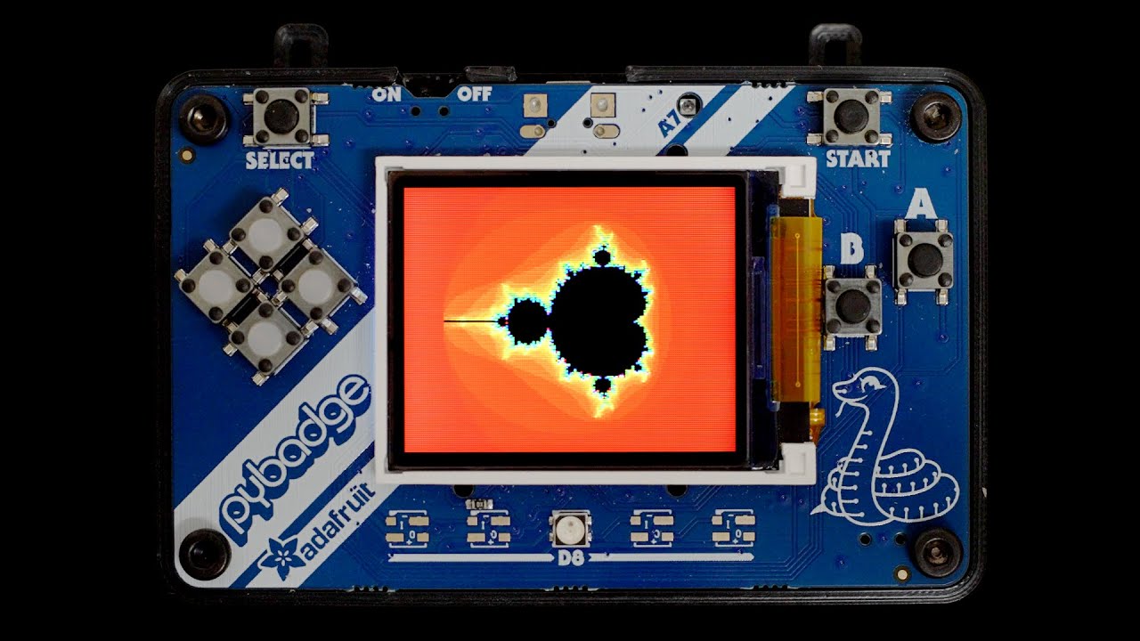
Here is a demo of my fast interactive real-time Mandelbrot renderer for the Adafruit PyBadge.
Source code can be found here...
https://github.com/movievertigo/Adafruit-PyBadge-Mandelbrot
A/B : Zoom in and out
D-Pad : Pan around
Start : Reset view
vagrant shard
cool, what kind of screen does the pybadge have?
edit: I don't think I'm supposed to ask questions here
 last sundial
If I wanted to do a display made of four 64x64 LED matrix panels for a total size of 128x128, would I be able to drive that with one Matrix Bonnet board and a raspberry pi 4?
grave nacelle
last sundial
If I wanted to do a display made of four 64x64 LED matrix panels for a total siz...
For that kind of question, you might have better luck over at #help-with-projects or #help-with-circuitpython . This channel is a place where people usually post to show off projects they've been working on. You might also take a look at this guide to see if it answers your question: https://learn.adafruit.com/rgb-matrix-panels-with-raspberry-pi-5
last sundial
oh gosh duh, i thought I was in help-with-projects
 warped siren
Not mine, but this could be fun to get going on the FruitJam when it comes out: https://github.com/ikjordan/picozx81
GitHub
ZX81 emulator for Raspberry Pi Pico. Contribute to ikjordan/picozx81 development by creating an account on GitHub.
uncut swallow
warped siren
Not mine, but this could be fun to get going on the FruitJam when it comes out: ...
It'd be great if it randomly ignored the 1st and 2nd "keyboard" inputs via serial.
sly rampart
I need to sit down and figure out the patch needed to let stdio-usb work in combination with a separate USB stack, even if needs to have a separate thread on the other core just for that.
I kinda stagnated because it's a hastle to deal with the stdio-serial versus stdio-usb but the stock sdk blocks using that with the common TinyUSB stack.
high imp
Boost Your KiCad Skills: 10 Essential Schematic Design Tips
https://youtu.be/dbtVgZGaFmE

Thanks PCBWay for sponsoring this video - https://pcbway.com/g/i8683S - Use this link for $5 new user free credit.
In this video I'll show you 10 tips and tricks that could help you to improve your skills designing a schematic in KiCad.
These tips and tricks will make you more efficient and help you make your designs even faster.
If you have o...
 fringe vault
I've been moving some of my projects over from Flux.ai to KiCad, and I've been finishing more of my PCBs in the process. This is my most recent one:
A PCB for building a 6DOF space mouse using hall effect sensors, based on ChromeBee's hall effect space mouse.
https://codeberg.org/whitelynx/hall-effect-space-mouse

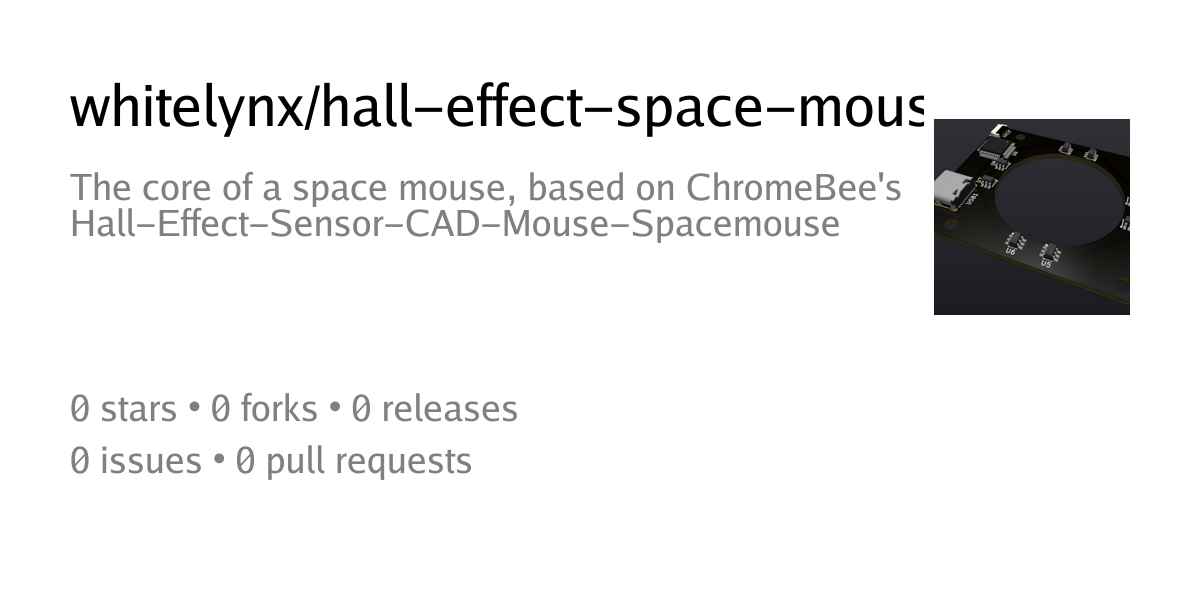
Codeberg.org
The core of a space mouse, based on ChromeBee's Hall-Effect-Sensor-CAD-Mouse-Spacemouse
limber temple
The pico-8 project, i finally completed it with a good piece of acrylic
 sacred timber
fringe vault
I've been moving some of my projects over from Flux.ai to KiCad, and I've been f...
sacred timber
fringe vault
I've been moving some of my projects over from Flux.ai to KiCad, and I've been f...
Nice job, is that rendered in KiCad too?
fringe vault
sacred timber
Nice job, is that rendered in KiCad too?
Yeah, that's just the built-in raytraced rendering 👍
 thin turret
gforth lets you define emoji as words so you could write entire programs in emoji. I'm not sure what to do with forth or this information but I needed to share it somewhere.
sly rampart
Many languages (including JS) allow UTF-8 these days including for variable/function names.
tropic sparrow
thin turret
gforth lets you define emoji as words so you could write entire programs in emoj...
I present to you: Bunnascript
 jade path
thin turret
gforth lets you define emoji as words so you could write entire programs in emoj...
jade path
thin turret
gforth lets you define emoji as words so you could write entire programs in emoj...
 clever stone
A little teaser for @exotic sierra showing CircuitPython running a stepper motor via the 74HC595 shift register IC. Max rotation has deliberately been throttled to 120RPM. 🏎️🏁
clever stone
clever stone
A little teaser for <@728676724522352733> showing CircuitPython running a steppe...
I finally diagnosed my issue with using TMC2209 stepper drivers. I had 2 out of 3 bad ones.
A tradeoff I will accept is the speed is a factor of how fast I can generate steps. Obviously I can move faster when there are 3200 micro steps in one revolution vs when there 12800 microsteps.
Once I reassemble the machine, I will k ow how fast I need steppers to go.
grave nacelle
This is a CircuitPython hypotrochoid curve drawing thing (like Spirograph) for Fruit Jam or Metro RP2350. Might be useful as a source of sample code for picodvi with 320x240 8-bit (RGB332) or 640x480 8-bit (RGB332) video modes. The 640x480 8-bit mode seems to require a board with a PSRAM chip (got MemoryError on the Metro RP2350 no PSRAM version).
Playground guide: Fruit Jam Hypotrochoid Spiral Maker
Github: samblenny/fruit-jam-spirals


 high imp
Complete design tutorial of a TCAL9539PWR breakout board in KiCad
https://youtu.be/61uLHVL8qCY

Thanks PCBWay for sponsoring this video - https://pcbway.com/g/i8683S - Use this link for $5 new user free credit.
Complete step-by-step PCB design process going through the schematic creation, layout, and routing of a breakout board based on the TCAL9539PWR 16 bit GPIO expander.
Wondering how you can support the channel?
https://ko-fi.com/mor...
 haughty anvil
Prototype board for what will eventually be a super miniaturized FPGA daughterboard. This one is an ICE40LP384 and a Winbond W25Q128JVSIQ

 twin dagger

This is a demonstration of my real-time fully interactive raytracer for the Adafruit PyBadge and PyGamer.
The source is available for you to build it yourself here...
https://github.com/movievertigo/Adafruit-PyBadge-RealtimeRaytracing
Controls
Stick/D-Pad: Look around
Stick/D-Pad + A + B: Move left/right/up/down
A: Move forward
B: Move backwar...
twin dagger
twin dagger
https://www.youtube.com/watch?v=JWj-BYXXXZw
A demonstration of my real-time fully interactive raytracer for the PyBadge and PyGamer.
The source is available for you to build it yourself here...
https://github.com/movievertigo/Adafruit-PyBadge-RealtimeRaytracing
Controls
Stick/D-Pad: Look around
Stick/D-Pad + A + B: Move left/right/up/down
A: Move forward
B: Move backward
Start: Pause/resume animation
Start + A: Increase animation speed
Start + B: Decrease animation speed
Start + Stick/D-Pad: Move light source
Select: Change scene
Select + A: Increase sphere count
Select + B: Decrease sphere count
twin dagger
twin dagger
https://www.youtube.com/watch?v=JWj-BYXXXZw
For best results, when compiling yourself, select the "-Ofast -funroll-loops" optimization settings and overclock as much as you can. My PyGamer seems to be stable at 200MHz and my PyBadge at 180MHz
exotic sierra
haughty anvil
Prototype board for what will eventually be a super miniaturized FPGA daughterbo...
ICE40 are so much fun to use, I’ve done a number of designs with the larger variants like the iCE5LP4K
haughty anvil
exotic sierra
ICE40 are so much fun to use, I’ve done a number of designs with the larger vari...
Yeah! I'm just getting into FPGAs and ICE40 is really awesome. The pricepoint is really good for a beginner, and the hardware setup is super simple. The open source tools are confusing but quite good once I figured it out. I'd love to play with some of the larger ones for a processor core or signal processor in the future, but for now 384 cells is MORE than plenty, especially given the generous IO count :]
nimble sapphire
Hey all, work has kept me from show and tell lately, but check this out :

Diabetic GO box, injection pen holder for the fridge, and a door wedge for wheelchairing through non ADA compliant doors
stark latch
Got the 3D-printed trackball (with scroll wheel + 3 buttons) working with an M0 Bluefruit. Wasn't sure the M0 would be able to interface with both the bluetooth module and the mouse sensor, but it works like a champ. 🎉

 sage yarrow
pixel aurebesh

 frail birch
xqc transcription device, very cool
sharp comet
grave nacelle
This is a CircuitPython hypotrochoid curve drawing thing (like Spirograph) for F...
those are cool! thanks for sharing!
grave nacelle
sharp comet
those are cool! thanks for sharing!
Thanks!
 main loom
The evolution of a project.
Several years ago I decided to make LED "ear rings" to wear while fursuiting. The first version was the black project box. Inside was a breadboard with a Trinket M0 on it. A USB cable out one side, and a 3.5mm audio socket out the other (this was repurposed to V2). Large, unwieldy, prone to error, but functional.
Later while commissioning a full fursuit I got it in my head to try something with it. By extension this ended up being the second version of the ear rings. My first ever circuit board, the green one in the middle. Switches to configure it on the fly, but a slightly obnoxious USB port, and a connection to the lights that could be plugged in wrong. Also had to desocket the chip every time for reprogramming. Better, but still room for improvement.
V3, the little red board on the right, something that looks almost professional. My third circuit board, and first attempt at SMD. No daughterboard hanging off, the lights cannot be plugged in wrong, no more audio cable being used as a data cable, a proper programming port. I have learned so much, come so far, and it all started as just being a bit silly.
Oh, and it has like 7 different animations that it randomly cycles through.

 peak oriole
Hi folks, looking for a simple inexpensive way to play sounds. I will be driving the audio from a Metro Mini. Just a few ~3 sounds. Thanks
grave nacelle
Made a swirly colors thing for RP2350 picodvi displays. The point is to generate palettes to use for making color swirl animations. I used the 320x240 16-bit video mode with an 8-bit bitmap (lets you pick a palette with 256 of possible 65536 colors). I made the gradient by looping through hue angle values (h) in the LCh color space then doing the color math to transform through Lab, XYZ, then finally sRGB. The Lightness (L) and Chroma (C) values can be adjusted with WASD key input in the serial console.
code on GitHub: https://github.com/samblenny/fruit-jam-color-gradient
Playground guide: https://adafruit-playground.com/u/SamBlenny/pages/fruit-jam-color-gradient-generator


 night nest
Pcm5102 DAC breakout via I2S?
sand grotto
holy moly Batman, I managed to poke and prod the adafruit RSA library and the pyasn1 project enough to generate and save my der/pem formatted keys... Now I can hopefully remote control my Tapo Switches in circuitpython 😈
 haughty anvil
I've succesfully deployed software on the ICE40 in a breadboard prototype, perfboard prototype, and finally after weeks of waiting for the boards, a custom PCB!
Since I've pulled it off three times now hopefully I can have the knowledge to integrate it into the layout of my final product...
 exotic sierra
haughty anvil
I've succesfully deployed software on the ICE40 in a breadboard prototype, perfb...
exotic sierra
haughty anvil
I've succesfully deployed software on the ICE40 in a breadboard prototype, perfb...
very cool! always nice to have designs work successfully
limber temple
Succefully ported the Mario clock to the Matrix Portal s3. Should i fork it?
 stark latch
This trackball model was generated in OpenSCAD, using 60+ parameters. The position and orientation (x/y/z plus pitch/roll/yaw in some cases) of the components, plus optional padding objects determine the shape of the shell.
You can specify mouse vs trackball, the number of buttons (up to 5), and optional scroll wheel.
The first image shows 3 stages of development, plus the final assembeled device.
I've also included a model for a 3-button mouse with side scroll wheel to demonstrate the range of configurations.

 sand grotto
New screens coming to WipperSnapper... Now available for featherwing OLEDs, plus some generic small 64x32 OLEDs more suitable for Ants 🐜 or Lego fans 🧱 [Just need ant sized batteries to match scale]
 untold sable
sand grotto
New screens coming to WipperSnapper... Now available for featherwing OLEDs, plus...
untold sable
sand grotto
New screens coming to WipperSnapper... Now available for featherwing OLEDs, plus...
What is this? Just a dummy plug? USB push button?
 sand grotto
untold sable
What is this? Just a dummy plug? USB push button?
sand grotto
untold sable
What is this? Just a dummy plug? USB push button?
usb magnetic cable, with charge and data, but with the cable end detached. They're pretty good, can bend safely, and rotate along with the quick disconnect, although initially I got lots of small metal bits stuck to them which wasn't so cool
untold sable
sand grotto
usb magnetic cable, with charge and data, but with the cable end detached. They'...
Ah yes, I know what you mean now. I forgot about those. I bet it was a lot of fun making sure you got all the little bits off.
frail birch
First project with a chip. testing a custom air-fuel gauge that will go in my car, using LED's instead of a number. Made an app in Assetto first, then shared memory to serial. Not really liking Python though, might try microlua or tinygo if the support is good enough
 acoustic nebula
I've created an upgraded version of a Pico 2 - LiPo battery support, 16MB flash, USB-C and common connectors
 sly rampart
Them steadfastly sticking to MicroUSB on the Zero 2 and Pico 2 are the largest obstacle to using those things, agreed. XD I have a literal bag of MicroUSB<->USB-C adapters just to avoid fighting with the MicroUSB ports.
I get why for backwards-compatibility but man I wish they offered a USB-C variant at least. Wonderfully done 'upgrade' version there!
exotic sierra
sly rampart
Them steadfastly sticking to MicroUSB on the Zero 2 and Pico 2 are the largest o...
Their reasoning is two fold, one cost and two everyone has micro USB cables laying around so the barrier to use it is incredibly low for the average person starting out
exotic sierra
acoustic nebula
I've created an upgraded version of a Pico 2 - LiPo battery support, 16MB flash,...
How well does it perform from a power perspective? I recall from the data sheet they were particularly concerned about the layout of the 1.1V regulator capacitors and specialized inductor.
acoustic nebula
exotic sierra
How well does it perform from a power perspective? I recall from the data sheet ...
I haven't done that many intensive projects with it yet as I've only received it recently but I'm assuming it would be fine. My manufacturer would only let me use specific components which I'm assuming reduces that risk. If anyone here is interested in where to find them, dm me.
sly rampart
exotic sierra
Their reasoning is two fold, one cost and two everyone has micro USB cables layi...
That was their reasoning for V1 but for V2 it was keeping backwards-compatibility for the form factor AFAIK mostly.
exotic sierra
Yeah, which tends to mean the original reasoning still stands. Either way, I do agree that USB C would have been better for a number of reasons
sly rampart
Nah it was purely a "2.0 can usually be swapped in to replace 1.0" thing, they're big on making new versions be usable to continue supporting existing projects using the tech. See also how long they kept the same form factor for RPi "and still called them "B" models despite no longer offering the "A" form factor on newer kit.
They made a decision on V1.0 and were (for better or worse) stuck with it now.
Pico, Zero, Pi 1 through 3 and even most things all the way to 5, etc.
frail birch
Simple spotlight for my GPU because it was almost not visible before (+wanted load rgb), using a neopixel 5050 button directly wired to 5v ADD motherboard header, works perfectly, everything is color controlled with openRGB for load/temp

 grave nacelle
Made a CircuitPython picodvi twisty-lines screensaver thing for Metro RP2350 and Fruit Jam, inspired by 1990's screensavers like After Dark's NightLines and Windows 95's Mystify.
https://github.com/samblenny/fruit-jam-lines-screensaver
https://adafruit-playground.com/u/SamBlenny/pages/fruit-jam-lines-screensaver
cc: @sharp comet


 sharp comet
grave nacelle
Made a CircuitPython picodvi twisty-lines screensaver thing for Metro RP2350 and...
sharp comet
grave nacelle
Made a CircuitPython picodvi twisty-lines screensaver thing for Metro RP2350 and...
Nice! those are rad!
sage yarrow
made a hygrometer for a certain herb plant of mine but not sure if I can share photos
 misty umbra
limber temple
The pico-8 project, i finally completed it with a good piece of acrylic
misty umbra
limber temple
The pico-8 project, i finally completed it with a good piece of acrylic
Hey @limber temple , I'm having a problem where some LED rows flicker when the brightness is set above 0.5. Do you have the same problem?
limber temple
misty umbra
Hey <@802490083412017153> , I'm having a problem where some LED rows flicker whe...
On what controller
misty umbra
limber temple
On what controller
I followed the following tutorial exactly:
https://learn.adafruit.com/led-matrix-wall-arcade

Build a Raspberry Pi Pico-8 game machine for your wall
limber temple
misty umbra
Hey <@802490083412017153> , I'm having a problem where some LED rows flicker whe...
Yes I do get that as well, on the 64x64 panels with the E-pin. Have not tried the D-pin ones yet
misty umbra
limber temple
Yes I do get that as well, on the 64x64 panels with the E-pin. Have not tried th...
thanks for the answer... 🙂 god that i`m not crazy... I also tried it with a 5V 20A power supply, unfortunately without improvement.
limber temple
PWM (pulse width modification) would help this I think, if it were implemented, but I'm just getting into the coding so I don't know where to start on implementing that into piomatter or if it can even be done
I know that it requires sudo (root level access) to do this on the raspberry Pi 4, and piomatter is designed to run without sudo. It takes control of hardware level pins
misty umbra
limber temple
PWM (pulse width modification) would help this I think, if it were implemented, ...
thanks anyway...I'll try to learn more about it. Since I'm using a dark acrylic coating, it would be good to achieve a brightness above 0.5. I currently have a Raspberry Pi 5 with 8GB connected.
limber temple
Yeah that should be plenty. I sent a pm to cut down on this channel, I was redirected to the help channels before
sand grotto
sage yarrow
made a hygrometer for a certain herb plant of mine but not sure if I can share p...
Maybe you can do some photo cropping and blurring regions, so it can't be used against you in a future situation [like when visiting a place with different laws]
stark latch
I think I'm finally satisfied with the code for wire/wireless trackball/mouse design I've been working on. I've posted the Arduino source on github (https://github.com/degroof/TrackballMouse) for anyone who's interested in using or modifying it. Here are three things that are currently running the code (wired left-handed trackball, wireless right-handed mouse, wireless scroll wheel).
 tropic sparrow
stark latch
I think I'm finally satisfied with the code for wire/wireless trackball/mouse de...
tropic sparrow
stark latch
I think I'm finally satisfied with the code for wire/wireless trackball/mouse de...
Nice job! it's really cool to see your prototyping and design of this
 turbid prism

this device (a MODBUS Isolator) uses a feather M0 to communicate with an industrial MODBUS to obtain process variables. it then sends the data over I2C to another M0. the 2nd M0 creates another MODBUS server so that a data acquisition system can retrieve the data.
Why? this allows an internet connected data acquisition machine to obtain plant process data while protecting the Plant MODBUS from outside interference ( ala STUXNET type attacks). Data flow is one directional and only a few registers are recognized by the 2nd server. If a hacker discovers the internet exposed server somehow, data on the plant server is protected since it cannot be changed.
clever stone
Yikes! The 3-Axis Camera Slider project has been going on for 25 days 😳
First “trial video” shows room for improvement. The keyframe sequencing is working well but I can see (and feel) the carriage is not rolling smoothly.
The rollers are “OK” when not shooting closeups but that is a use case.
 onyx hemlock
I've been working on a DIY smoker conversion for my Weber grill. I finally completed the shell design and wired up the final pieces and installed them with heat set inserts.


Servo and fan control and power are sent over an Ethernet cable split out into the appropriate signals, grill temperature is measured via an RTD for PID control using the fan and servo (air damper), and there is a meat temperature probe as well. Both temp devices are connected via 3.5mm headphone jack.
 wanton spire
I have probably spent far too much money on the filament shapes and letters since they came out but they are just so fun! But my only complaint is that I wish there was a way to very simply place and remove letters like in those signs that you see. So I made about 20 different 3d printed versions supporting both parallel and serial connections and finally landed on this design based on the replacement breadboard strips which were perfect for my needs.
I put the model on makerworld in case it’s something anyone else has been wanting something like it. https://makerworld.com/models/1562649


This is an entirely new model from the ground up, inspired by the same problem I tried to solve in my previous model. In this case, the model is designed for serial wiring and relies on new parts that can be sources from Adafruit. DescriptionWhen Adafruit introduced LED filament letters earlier this year, I knew I wanted to make a woodworking p...
sand grotto
Not my project, but felt like this audience would appreciate the heads up for a floppy based whack-a-mole https://hackaday.com/2025/07/01/whack-a-disk/ (the extra work to make the discs jump is commendable)
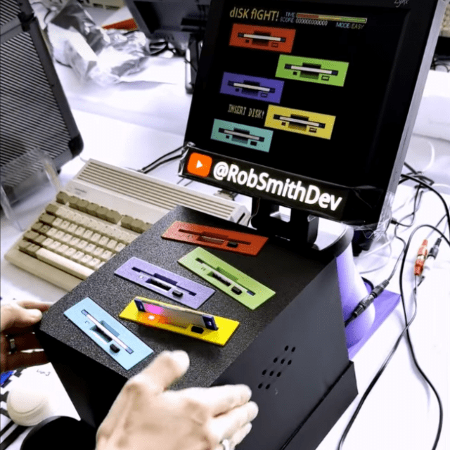
By now most floppy disks have been relegated to the dustbin of history, with a few exceptions for obscure industrial applications using legacy hardware and, of course, much of the world’s nuc…
 maiden wedge
is there a Show and Tell this evening?
sand grotto
maiden wedge
is there a Show and Tell this evening?
unfortunately not: #live-broadcast-chat message but there should still be Ask an engineer at 8/8:30
grave nacelle
For folks interested in CircuitPython USB host MIDI stuff on Fruit Jam or Metro RP2350, I've been working on a USB host MIDI tester thing. Rolled my own MIDI device driver on top of the usb.core.Device API because adafruit_usb_host_midi doesn't support the features I want (efficient raw midi packet access, etc). Anyhow, my code is working reasonably well for dumping notes and cc changes from my drum sequencer out to the serial console (hardware: Fruit Jam rev B + powered USB hub + BeatStep Pro). Planning to come up with some kind of note and channel activity indicators for the DVI output. Not sure what would happen to MIDI latency if I added synthio output (leaving that for a future project). No documentation or guide for this as of yet, but the code has lots of comments. Curious what people think (cc @warped siren ).
https://github.com/samblenny/fruit-jam-usb-midi-tester

 warped siren
grave nacelle
For folks interested in CircuitPython USB host MIDI stuff on Fruit Jam or Metro ...
warped siren
grave nacelle
For folks interested in CircuitPython USB host MIDI stuff on Fruit Jam or Metro ...
woah this is really cool! USB host stuff is always so hit-or-miss. I really like your efforts on maximzing performance
exotic sierra
Working on an old light controller that i'm planning to use in an indoor greenhouse to keep veggies growing or at the very least, have an easier and more consistent place to start them before the growing season. I am going to add a USB C PID controller so I can run higher voltage LED strips from it.
 sacred timber
exotic sierra
Working on an old light controller that i'm planning to use in an indoor greenho...
sacred timber
exotic sierra
Working on an old light controller that i'm planning to use in an indoor greenho...
I'm one of those fence-sitters who's played with EasyEDA and Kicad but never quite gone through the entire process to end up with a physical board. I'm just curious: what software are you using, which fab are you planning to use, and any tips for a semi-beginner? (I'm from the bygone era when we made boards with clear mylar, black tape, sheets of dots and photo-etch...)
exotic sierra
sacred timber
I'm one of those fence-sitters who's played with EasyEDA and Kicad but never qui...
Using KiCAD, I usually will use OshPark or JLCPCB for making the PCB. I get stencils so I can assemble them easier.
Tips for beginning? Start with a useful small design, usually like a sensor you want to try out. Start with easy packages to place, route, and fix if necessary. Data sheets are your friend, manufacturers have app notes with recommendations for schematics and that can be super helpful for taking a lot of guessing out of part picking.
sacred timber
exotic sierra
Using KiCAD, I usually will use OshPark or JLCPCB for making the PCB. I get sten...
Thanks very much! Your PC board looks really professional, which is why I asked.
I've been doing electronics for ages, so I totally agree, datasheets are sometimes kinda amazing, usually written by very smart and helpful people. I started a robot club at a local high school and that's one of the things I'm trying get across to the students. I was working on a too-complicated guitar pedal design and had the datasheets for some VCAs made by THAT Corp. in Milford, MA. I was impressed by their hardware, but even more by their datasheets and tech notes. I contacted their tech support and even had one of their engineers help me through some of the thornier issues. A great company is great products, great documentation, and great support. I wish more companies understood it requires all three.
I think the first actual PC board I'll do will be a power distribution board for my next small robot. It won't have any pick-and-place parts so that'll make it easier.
limber temple
Taught myself how to make it just return a different string for month and day values
Test and fix baby

 untold birch
Maybe someone else here also has a WaveShare PhotoPainter (e-ink frame with RP2040), I've made the project compatible with Arduino IDE. Alongside that I've also tried to clean things up a bit, fixed a few errors and a bunch of warnings.
GitHub
This is a fork of PhotoPainter for WaveShare picture frame displays that can be built and uploaded using the Arduino IDE. Depends on Avamander/FatFS-SPI library being installed separately. - Avaman...
Planinning on adding WiFi-Nina support to it as well. If it's not too much hassle I'll also update the FatFS library and remove a few layers of unnecessary abstraction.
 stoic hearth
Do you like Math & Clocks. We've set up a project of a Math Clock, that gives you present time using Math expressions. We've made it using Adafruit components, like Matric Portal S3 & LED Matrix screens and a 3D printer. Take a peek? -> www.time-math.com
 stable plover
I have been busy making pinouts. So many pinouts!
(ノ◕ヮ◕)ノ*:・゚✧
- RP2350A - https://rp2350a.pinout.xyz
- RP2350B - https://rp2350b.pinout.xyz
- ESP32-C3 - https://esp32c3.pinout.xyz
- ESP32-C5 - https://esp32c5.pinout.xyz
- Teensy4.0 - https://teensy40.pinout.xyz
- Minimalist version of the O.G. site for Raspberry Pi - https://pi.pinout.xyz
The A and B variant chip pinouts for RP2350 also have function planners/search and JSON export. A nice companion for planning out or debugging a design. Enjoy!
sacred timber
stable plover
I have been busy making pinouts. So many pinouts!
(ノ◕ヮ◕)ノ*:・゚✧
* RP2350A - htt...
Ahh those are yours! I wish to thank you, very helpful web site 🙏🏼⭐️
smoky heath
A Teensy! Nice!
grave nacelle
Progress update on the USB host MIDI tester for Fruit Jam that I posted about last week... Visualizer using picodvi works well now. Background image loads with a grid of dots for possible midi notes. NoteOn events replace the dot with a white rectangle. NoteOff events turn the rectangle black. Note grid ends up working like a heat map of which channels and notes have activity. CC and SysEx get printed in the bottom left pane. USB connection status info goes in the bottom right pane.
 sacred timber
grave nacelle
Progress update on the USB host MIDI tester for Fruit Jam that I posted about la...
sacred timber
grave nacelle
Progress update on the USB host MIDI tester for Fruit Jam that I posted about la...
Nice looking visualisation!
 digital marsh
Howdy! Here's my WS2812-based real time display of Seattle's Link light rail system.
It's written entirely in Rust for ESP32 chips (tested on a ESP32-WROOM-32 and ESP32-S3-WROOM). It includes the 1 and 2 lines as they currently are, with support for the future Federal Way extension and completed 2 line across Lake Washington up to Lynnwood City Center.
While some parts of the code are hard coded for this specific project (particularly the indices for the LEDs), it's flexible enough that you could fairly easily alter it to display any transit line in the Puget Sound area that uses the One Bus Away API.
 grave nacelle
Progress update on the USB host MIDI tester for Fruit Jam that I posted about la...
grave nacelle
grave nacelle
Progress update on the USB host MIDI tester for Fruit Jam that I posted about la...
MIDI tester/visualizer thing is finished. Playground guide is at https://adafruit-playground.com/u/SamBlenny/pages/fruit-jam-usb-host-midi-tester. This now includes a MIDI thru feature to echo filtered input events from the downstream MIDI controller upstream to the Fruit Jam's host computer using usb_midi.PortOut. This code might be a good starting point for MIDI controller remapping or filtering projects.
exotic sierra
Not tech, but something I built this last week or so. A coffee table :)
 grave nacelle
Finally got around to making a demo video for my Fruit Jam USB midi tester/visualizer thing. For the video I've got a BeatStep Pro plugged into the Fruit Jam, the Fruit Jam plugged into a Mac, and the Mac running a drum & lead patch in VCV Rack 2.
https://www.youtube.com/watch?v=O1BcIFmea3w

Demo of my Fruit Jam USB Host MIDI Tester code with BeatStep Pro plugged into the Fruit Jam and the Fruit Jam plugged into a Mac. Mac is running VCV Rack 2 with a simple drum + lead patch. To avoid power and ground loop troubles, I used the BeatStep Pro bundled ground loop fixer dongle thing with a separate USB power supply.
 turbid trench
I wanted to share with you a small module I have been working on lately. It is a compact MicroMod, fully compatible with the Sparkfun ecosystem. I have a few projects piped up and I hope to reduce the time and money required by creating a functioning module with all the required things.
Besides the main star of the show(STM32H757 MCU), the SDRAM, Flash and Wifi, the variety of sensors will be a nice addition to the set, all in a small 23x27mm M.2 formfactor. I am specially excited to test the DSI and the 9DoF IMU sensor-fusion. Though, OTA is also a very cool feature, specially for development.
Let me know what you think about it. Any suggestions are welcomed, even encouraged.

 limber temple
Here's my forked repo for the combined library animated gif example. Please note this requires to roll back board support for esp32 to version 3.13
GitHub
RGB matrix library for Arduino. Contribute to sub-zerohm/Adafruit_Protomatter development by creating an account on GitHub.
 brave thistle
Hi everyone, I published a new repo on Github about my current project. It uses an Adafruit Feather ESP32-S3 TFT board as MQTT Publisher to remotely command the ambient lights on the back of a Pimoroni Presto device. It also can send / show data of a BME280 sensor of a Pimoroni multi-sensor-stick. See: https://github.com/PaulskPt/Presto_MQTT_multi_topic_subscriber/blob/main/README.md
GitHub
Pimoroni Presto MQTT multi topic subscriber. Contribute to PaulskPt/Presto_MQTT_multi_topic_subscriber development by creating an account on GitHub.
warped siren
I made a simple "visual diff" tool for KiCad PCBs when using git. https://gist.github.com/todbot/aa644de99d9dacf0307267ea03fdbc64
grave nacelle
This is a little USB host MIDI synth thing for Fruit Jam that I've been working on. Should be pretty easy to modify it for Metro RP2350 + TLV320 DAC breakout board with some minor code changes. It pretty much works now, but I need a better way to adjust the volume (currently requires code edits). https://github.com/samblenny/fruit-jam-portable-midi-synth cc @warped siren
 grave nacelle
Decided to just leave the hardcoded volume control as-is and write it up as a Playground guide:
https://adafruit-playground.com/u/SamBlenny/pages/fruit-jam-portable-midi-synth
 acoustic shale
This is a fully functional poltergust 5000 from Luigi's Mansion Dark Moon i built thanks to my Library's Maker Space. Built with a handheld vacuum in the handle to provide suction and built in lights custom wired by me

 acoustic shale
 warm shoal
isnt that a 500-1000 dollar vacuum lol
warm shoal
isnt that a 500-1000 dollar vacuum lol
Nope, it's made with a $39 pre.Owned bissel and a fifteen dollar handheld vacuum
warm shoal
nice
 signal stirrup
I am working on an open source GUI design for Raspberry Pi with enclosure for mounting on mini racks (2U). I recorded a video of the design process (part 1): https://www.youtube.com/watch?v=9Ob_HDO66_8. Would love to hear your thoughts and feedback on this design


In this video, I am walk you through the re-design of GUI module for Raspberry Pi that can be mounted on a server rack for monitoring home lab services.
This is a multi-part video and I tried to keep the first part short and high-level. In next parts, I get into the KiCAD design of the PCB and 3D design of the enclosure.
0:00 Why am I making ...
acoustic shale
And as I stated, this prop is a functional piece. A weak vacuum cleaner, but a vacuum cleaner nonetheless
 narrow idol
A little Gaming Console inside of a VHS Tape, This is ¥enPocket 80'


 untold sable
narrow idol
A little Gaming Console inside of a VHS Tape, This is ¥enPocket 80'
https://ada...
untold sable
narrow idol
A little Gaming Console inside of a VHS Tape, This is ¥enPocket 80'
https://ada...
Super cool! Although I have to admit, I would like to see a full color TFT display in there rather than a monochrome OLED. But looks easily upgradeable. Also, nice stache! There was no way I could grow that at 16. Also next version do it with a Qt Py board and load it into a Digital-8 Tape case. 👍
Now time to go to the basement and maybe sacrifice some of those old Disney taps moldering away down there. 😆
 cloud elm
While not an electronic gizmo/gadget related, I'd like to share out a project I've been working on, off and on for the last ~2 years or so called
Link Start, a free platform where gamers can:
🎮 Show off what they play
🕹️ Find others who play the same games
⚔️ Challenge others
💬 And just connect with fellow gamers without needing to juggle 10 Discords
Still small but hopefully growing, and I’d love for more real gamers to help shape it.
If it sounds cool, please check it out!
https://linkstart.gg
Thanks and much love if you give it a peek! ❤️

 jovial pilot
If you use a marble as a button and put an LED behind it, you can make it glow with all the magic of a wizard’s orb.

 fervent finch
Used the Adafruit i2c solenoid board to make a midi controlled drum kit. Going to finish wiring it and add some pickups next.
lucid bloom
Took a pi zero 2, meshpocket and LCD hat, made a portable meshtastic bbs that can run for over 24 hours because the meshpocket is a 10000mah battery pack. LCD code monitors journalctl for new messages and extracts sender from there. The eink display shows the last received message. I still need to customize it to my liking but it is functional at this point.


White cable is a magnetic serial connection and the braided cable is power
 real bobcat
This is my first project and by no means finished. I have a rotary encoder that will change the image on the matrix and play a sound. Just finished soldering the QTpy and BFF stack. Still need to merge the some of the code and test. Animations are not easy to come by so for now it flips between static images.
 grave nacelle
I like that construction style. Reminds me of aerial views of a city with skyscrapers.... like the speaker is a stadium or something.
real bobcat
I was tempted to color the QTpy holder to match.
sharp comet
Random weekend idea come to fruition. "Love Language" an encoder/decoder that converts between ASCII text and emoji hearts. Such as Hello <-> 🩵🩶💜💙💜💞💜💞💜💝 https://foamyguy.github.io/Love_Language/index.html
errant pasture
Been making a lots of progress on a tetris clone for the fruit jam recently... 👀 🕹️ https://github.com/relic-se/Fruit_Jam_Fruitris


GitHub
Tetris, Fruit Jamified! Contribute to relic-se/Fruit_Jam_Fruitris development by creating an account on GitHub.
grave nacelle
errant pasture
Been making a lots of progress on a tetris clone for the fruit jam recently... ...
I like how you used asyncio for the input. I'm wondering if it would be possible to do something similar for USB host MIDI controllers and gamepads.
errant pasture
grave nacelle
I like how you used asyncio for the input. I'm wondering if it would be possible...
I haven't played around with usb host midi enough, but I've definitely used it for uart and usb client midi
errant pasture
Got my first alpha release out! Any fellow fruit jammers want to give Fruitris a try? (and let me know what breaks?) https://github.com/relic-se/Fruit_Jam_Fruitris


GitHub
Tetris, Fruit Jamified! Contribute to relic-se/Fruit_Jam_Fruitris development by creating an account on GitHub.
real bobcat
That is super sick. I can't wait to get my hands on a FruitJam.
short summit
errant pasture
Got my first alpha release out! Any fellow fruit jammers want to give Fruitris a...
I can't seem to get it to run - what's the right way to install it?
errant pasture
short summit
I can't seem to get it to run - what's the right way to install it?
Have you downloaded "fruitris.zip" from the release? (https://github.com/relic-se/Fruit_Jam_Fruitris/releases/tag/1.0.0-alpha.0) You should be able to extract and copy + paste it directly into your CIRCUITPY drive.

GitHub
First fully playable version of the game. I will likely add additional features before final 1.0.0 release.
Full Changelog: https://github.com/relic-se/Fruit_Jam_Fruitris/commits/1.0.0-alpha.0
errant pasture
You can also get it running on Fruit Jam OS if you install 2 missing prerequisites: circup install asyncio adafruit_hid. However, there's a bug right now that when you exit the application, you lose keyboard input in the OS.
short summit
I did install those
short summit
errant pasture
Have you downloaded "fruitris.zip" from the release? (https://github.com/relic-s...
It's working - I did download the source instead of the right files (oops!) - thank you!
 cursive gate
My take to fix broken adafruit wordle project. Runs on as small as QT Py 4mb
https://github.com/FriendlyNGeeks/ESP-REACTLE

GitHub
Contribute to FriendlyNGeeks/ESP-REACTLE development by creating an account on GitHub.
grave nacelle
After some discussion with @errant pasture on gamepad stuff for Fruit Jam, I decided to have a go at implementing a two-player USB host game controller thing. Turns out it works fine once the asyncio.sleep() delays are dialed in. This code supports a small handful of game controller types incluing Xinput (Xbox 360 compatible), Switch Pro compatible, the generic SNES controller from the Adafruit shop, and HID boot keyboards (with mapping for WASD, arrows, ZXCV, etc). Will probably write this up as a Playground guide, but I haven't done that yet. For now, there's code at https://github.com/samblenny/fruit-jam-two-gamepad-demo
 grave nacelle
Just posted the two gamepad demo video and guide:
https://www.youtube.com/watch?v=vKUXH_GwwaI
https://adafruit-playground.com/u/SamBlenny/pages/fruit-jam-two-gamepad-demo

This is my third iteration of a CircuitPython USB host gamepad tester, now with support for two controllers.
sharp comet
Fun magic trick effect using the new NeoPot. Audience member can freely select any color on the knob. Performer can catch the color in their hand and then throw it to another NeoPixel strip using the magic of a CircuitPython, a ToF sensor and espnow.
real bobcat
I have neopot arriving today. Am hyped. I hope we get a neopot with stemma/qt at some point.
sharp comet
It is a lovely little trinket. Agree'd stemma would be sweet!
zealous eagle
I wonder if those encoders would work with the I2C Quad Rotary Encoder Breakout with NeoPixel?
sacred timber
zealous eagle
I wonder if those encoders would work with the I2C Quad Rotary Encoder Breakout ...
Same basic idea, I see no reason why not.
 hot gate
Have you seen this Pokémon? https://www.instagram.com/reel/DNdfu3Mtgdz/?igsh=anhtaWtwejl4d3Zk
⚡️A wild Pikachu appeared… but this time, it’s robotic, 3D printed. And coded with AI.
Meet the Otto Pikachu—born from a mashup of pop culture, childlike imagination, and some serious maker magic. 🤖🎨
We used @chatgpt to conceptualize it, @makersempire to design it, @josefprusa printers to bring it to life, and @hp_robots Otto s...
 Instagram
grave nacelle
Instagram
grave nacelle
As part of my recent dev quest to find and fix some USB bugs in the CircuitPython core, I'm trying to wrap my head around how control flow works in the USB code. It's kinda tricky with background tasks, callbacks from the TinyUSB code, and so on. To help build a better mental picture of what's going on, I've been messing around with the cflow code analysis tool and the graphviz graph generating tool. The attached PNGs are the end result. Details on the intermediate command line stuff available at https://adafruit-playground.com/u/SamBlenny/pages/circuitpython-core-dev-debug-tricks.


 sly rampart
I will admit, I've gotten bit a few times by the tiny USB stack refusing to be used in combination with USB serial on RP2350 based stuff. I think there's some work in progress to allow that eventually, but boy howdy it's annoying not being able to use the second USB port if you want to enable the USB serial console so I need to use an actual pico debug tool to have a serial console in that case.
grave nacelle
Are you speaking of enabling a second cdc serial port on the USB device interface? Or, maybe of connecting a USB serial device to the RP2350 host interface? I've never tried either of those.
sly rampart
The built-in serial support for things like printf includes running over USB serial on the same cable you would connect the RP2350 too for programming, however it's incompatible with tiny USB to run it in that mode unfortunately. I haven't dug into the exact specifics of why.
grave nacelle
Does it work for you if you try something like,
mp_printf(&mp_plat_print, "I am a format string %d\n", 1234);
I was trying some printf debugging of that sort last night and it seemed to work fine. That output got mixed in with normal output from my python code. Didn't always flush immediately, but I kinda expected that because I was running test code that was loading down TinyUSB.
[edit: note that I was programming with UF2 files over USB mass storage and using USB CDC serial for the console]
sly rampart
I'll give that a whirl when I'm home later today, and it might have been fixed by now and I'm running on outdated information from a month or so ago. Let's face it things are moving at a very rapid pace for RP2350 stuff.
Also, sincerely, thank you for all the work you've been putting in Sam.
grave nacelle
You're welcome. So much of the progress is from tannewt's work over the winter and spring too. We all benefit from this stuff working better. It's gonna be fun to see what people build with it.
next star
I'm a stage lighting/sound designer by trade, and I have a lot of LGBT friends who are dealing with increased hatred and persecution in the US.
I've been prototyping an inexpensive but meaningful holiday gift that I can mass produce by hand, letting them know that they are welcome and appreciated in my tribe.
So far the colors simply slowly cycle, but I'm studying to add a mic and FFT for some sound reactivity (though the math is painful). The µcontroller is a cheap ATtiny85.

 low pulsar
next star
I'm a stage lighting/sound designer by trade, and I have a lot of LGBT friends w...
low pulsar
next star
I'm a stage lighting/sound designer by trade, and I have a lot of LGBT friends w...
Nice! (I've played a bit with audio filtering on a attiny412. Can sympathize with the constraints 🙂. Still, it had a surprisingly nice set of peripherals.) Good luck!
next star
low pulsar
Nice! (I've played a bit with audio filtering on a attiny412. Can sympathize wit...
Thanks for the encouragement. Here's another picture of the kirigami sculpture with the lights on.
 grave nacelle
@sly rampart You might like this... I figured out how to use the pico-sdk gpio functions to control the Fruit Jam's onboard red LED for some 1-bit low latency debugging (note that LED is active low and shared with IR decoder output). This diff is set up to turn the LED on when a USB device is plugged into a USB host port and off when a device is unplugged:
diff --git a/shared-module/usb/core/Device.c b/shared-module/usb/core/Device.c
index c9df0cf738..f650ed318a 100644
--- a/shared-module/usb/core/Device.c
+++ b/shared-module/usb/core/Device.c
@@ -18,16 +18,35 @@
 #include "supervisor/shared/tick.h"
 #include "supervisor/usb.h"

+// === DON'T COMMIT THIS ===
+#include "hardware/gpio.h"
+#define FRUIT_JAM_LED_PIN (29)
+#define DEBUG_GPIO_OUT_LOW(pin) { \
+    gpio_put(pin, 0); \
+    gpio_set_dir(pin, GPIO_OUT); \
+    gpio_set_function(pin, GPIO_FUNC_SIO); \
+}
+#define DEBUG_GPIO_HIGHZ(pin) { \
+    gpio_set_function(pin, GPIO_FUNC_NULL); \
+}
+// =========================
+
 // Track what device numbers are mounted. We can't use tuh_ready() because it is
 // true before enumeration completes and TinyUSB drivers are started.
 static size_t _mounted_devices = 0;

 void tuh_mount_cb(uint8_t dev_addr) {
     _mounted_devices |= 1 << dev_addr;
+    // === DON'T COMMIT THIS ===
+    DEBUG_GPIO_OUT_LOW(FRUIT_JAM_LED_PIN);
+    //mp_printf(&mp_plat_print, "m%x\n", dev_addr);
 }

 void tuh_umount_cb(uint8_t dev_addr) {
     _mounted_devices &= ~(1 << dev_addr);
+    // === DON'T COMMIT THIS ===
+    DEBUG_GPIO_HIGHZ(FRUIT_JAM_LED_PIN);
+    //mp_printf(&mp_plat_print, "u%x\n", dev_addr);
 }

 static xfer_result_t _xfer_result;
 cunning lava
Since the xiao sense s3 has a camera, I figured it would be nice to have a carrier board for it, with a display, encoder, i2s speaker and battery holder.

 neat torrent
I made a 10mm wide CircuitPython platform for Eurorack modular a few years ago and never really told anyone. You see, I was having some trouble getting going with CircuitPython, so one of us (at OAM) wrote the firmware in C++. It was only a couple years later that I wrote a python version. So I’m sharing it here and now.
It’s called Uncertainty. It has a (slightly wonky) CV/gate input and 8 gate outputs. Using PWM you can get 7-bit’s of PWM out of the gate outputs. It’s a funny little machine. It is open source software and hardware with a CC BY-SA license.
Link to our product page, but I’m only sharing it for informational purposes and will gladly remove it if asked:
https://oamodular.org/products/uncertainty
This is the relevant part of the repository for Uncertainty:
https://github.com/oamodular/uncertainty/tree/main/software/circuitpython

Olivia Artz Modular
We are currently sold out, but synthCube, Analogue Haven, Photosynthesis, Perfect Circuit, Escape From Noise, and Signal Sounds have Uncertainty in stock. Uncertainty is a tiny gate-processor, VU meter, and open-source platform for Eurorack. Out of the box, Uncertainty is a stochastic gate-processor that randomly drops

GitHub
Contribute to oamodular/uncertainty development by creating an account on GitHub.
sacred timber
neat torrent
I made a 10mm wide CircuitPython platform for Eurorack modular a few years ago a...
These are US$182 each for a 2U module?
neat torrent
2HP, yes. We’re working on an entirely through-hole version (still 2HP) that could be available as a kit or easily fabricated by any number of service.
neat torrent
(they are 3U)
lean elbow
Is it okay to show off PICO-8 games here? Seeing JP playing one of them I realized that I never did post about mine, so here goes! I recently made 2 games for pico-8, one is a retro-arcade rogue-lite shooter, and the other is a smaller more experimental game about putting on a fireworks show in the desert. They're both free and can be played in the browser (or even better, on JP's LED matrix wall arcade!). I definitely recommend playing with a controller for Star Captain 32767.
https://aaronpendley.itch.io/

itch.io
clever stone
Finally 🥵 finished my Osborne 1 RestMod with dual floppy emulators. The rotary encoders were shortened to fit with the keyboard closed. Stubby USB storage is used for the same reason.
I even tracked down an original 300 baud modem.
https://bsky.app/profile/bradanlane.bsky.social/post/3lwz6wxogf22n

My Osborne 1 RestMod is finished!
I started this 15 months ago and it's my first UFO (un-finished object).
The magic comes from a custom "interceptor" PCB I created. It go in-line with the exiting floppy cable. There are no permanent mods to the machine.
I even found the original 300 baud model.

 Bluesky
·
Bluesky
·


There is a video demo too.
https://bsky.app/profile/bradanlane.bsky.social/post/3lwzbioa54k2g

-# ↩ Bradán Lane (@bradanlane.bsky.social)
Demo video of the Osborne 1 with dual floppy emulators 😎
Bluesky
·
nimble sapphire
Hi all! I've been a bit absent fdue to life.
low pulsar
clever stone
There is a video demo too.
https://bsky.app/profile/bradanlane.bsky.social/post/...
(not a vintage collector) but this is one hardcore project! congratulations on seeing it through, very nice 🎉
clever stone
low pulsar
(not a vintage collector) but this is one hardcore project! congratulations on ...
I wanted to do an Osborne 1 because it was the computer I took to university.
I wanted this restoration to be as original as possible but I also knew I wanted USB "floppies" because original 5-1/4" floppies are getting harder to find and they degrade.
I enjoyed the challenge of shoehorning two emulators into a single storage slot and having everything recessed so the case closes normally.
Beyond all the floppy drive wizardry, I had to replace the original leather handle and I had to whiten the case (which was very yellow when I bought the computer off eBay).
 sly rampart
Incredibly job un-yellowing the plastic, well done!
jade path
I remember seeing someone who made "floppies" as large form factor micro SD card adapters, which was a cute way to keep the floppy experience
but that's quite a restoration job, well done
nimble sapphire
 nimble sapphire
jade path
but that's quite a restoration job, well done
nimble sapphire
jade path
but that's quite a restoration job, well done
Yep I have one of those. If you plug it in to power the screen shows what's on it, if you plug it into a computer it lets you transfer.

 gusty shard
Fun with ePaper. It draws something new whenever it gets a message via mqtt.
 clever stone
gusty shard
Fun with ePaper. It draws something new whenever it gets a message via mqtt.
clever stone
gusty shard
Fun with ePaper. It draws something new whenever it gets a message via mqtt.
ePaper projects open up some unique possibilities 👍🏼
 minor cradle
Made bad apple run on 64 LEDs
tropic sparrow
minor cradle
Made bad apple run on 64 LEDs
Bad Apple on Gut Bacteria when?
(context) https://www.engadget.com/heres-a-video-of-doom-running-on-gut-bacteria-proving-you-really-can-play-the-game-on-anything-184629896.html

Engadget
An MIT researcher has gotten the 30-year-old computer game Doom running on actual gut bacteria. The frame rate is really bad, as the game would take nearly 600 years to beat.
minor cradle
tropic sparrow
Bad Apple on Gut Bacteria when?
(context) https://www.engadget.com/heres-a-video...
😭😭 daym broooo what did I just witness 🥀 🤣🤣
glad roost
it's using the bacteria as a display. They are not doing computation
real bobcat
still very cool as a stepping stone to something greater
sacred timber
real bobcat
still very cool as a stepping stone to something greater
A walking, talking android made entirely of bacteria 🦠
real bobcat
Bacteria floats around in the air. So I could see some sort of organic displays appearing out of "thin air". Probably would nee some sort of net to bring them closer together.
 potent edge
figuring out cad software with plasticity, but i made a lil frame for the touchscreen pimoroni square hyperpixel xp for people who need a little protection on that screen
put the file up here if anyone wants it
https://makerworld.com/en/models/1752460-pimoroni-hyperpixel-xp-square-touchscreen-frame
https://www.printables.com/model/1401142-pimoroni-hyperpixel-xp-square-touchscreen-frame
 gusty shard
Running beta.3 on Pico W. Looking good so far!
untold sable
gusty shard
Running beta.3 on Pico W. Looking good so far!
No show? Only tell? 😜
gusty shard

 stoic mauve
I built an on-call beeper. Using an ESP32 feather.

Building a modern beeper from an ESP32 Adafruit Feather and a custom 3D printed shell. I created a true on-call pager for Sentry.io Hack Week 2025.
Full build on my blog: https://techsquidtv.com/blog/i-made-an-esp32-on-call-beeper/
If you enjoyed this, you may also enjoy my other account @LostPixelLore , where I have built a VHS Tape Cleaner....
errant pasture
Got more of a "Show & Tease" here (+kitty cat). New Fruit Jam game coming soon....... 🐍

 grizzled siren
Introducing WebScreen Serial IDE: https://serial.webscreen.cc
A modern, browser-based IDE for WebScreen devices with dual theme support. It combines serial communication, code editing, and command execution in one place.
No more SD card swapping. You can write JavaScript apps directly, upload instantly, and run commands like ping, wget, backup, stats, monitor, or manage settings from webscreen.json.
- Firmware: https://github.com/HW-Lab-Hardware-Design-Agency/WebScreen-Software
- IDE: https://github.com/HW-Lab-Hardware-Design-Agency/WebScreen-Serial-IDE
Learn more in our blog posts:


GitHub
WebScreen Firmware. Contribute to HW-Lab-Hardware-Design-Agency/WebScreen-Software development by creating an account on GitHub.

GitHub
Build WebScreen apps directly from your browser. Contribute to HW-Lab-Hardware-Design-Agency/WebScreen-Serial-IDE development by creating an account on GitHub.
 scarlet atlas
Hi everyone, I used embedded Rust and created an I2C device driver for the DPS310 temperature and pressure sensor. I was able to read pressure/temperature with the Raspberry Pi Pico 2 W. It was a great learning experience since I learned how to create embedded Rust programs for the Raspberry Pi microcontrollers.

GitHub
An I2C device driver for the DPS310 temperature and pressure sensor. Made with embedded Rust for the Raspberry Pi Pico 2 W. - GitHub - perrylson/rust-dps310-driver: An I2C device driver for the DP...
low pulsar
scarlet atlas
Hi everyone, I used embedded Rust and created an I2C device driver for the DPS31...
Nice 🙂 didn't realize Rust would be an.option on the Pico 2. Very cool.
nimble sapphire
Radio go box - radio , antenna, batteries, charger and earpieces
 potent edge
Building a game handheld pi5. Still figuring out the base and it feels wrong how small it is now (a CM5 16gb with a fan cooler and adapter attached to a waveshare nano board b. Hyperpixel xp attached with GPIO)
trying to consider if its a good idea to use a GPIO extender cable with it, but who knows
 errant pasture
Showing off our new game for the Fruit Jam! Take a look 👀 https://youtu.be/dXtbP7y0yBM
 grave nacelle
woah! this is awesome!
 bold tide
as a total noob to it all, adafruit has been life saver for learning. Didn't even know what an ESP32 was before this but pretty stoked about this project. Cyberpunk Spiderman Mask complete.


 lapis jasper
errant pasture
Showing off our new game for the Fruit Jam! Take a look 👀 https://youtu.be/dXt...
lapis jasper
errant pasture
Showing off our new game for the Fruit Jam! Take a look 👀 https://youtu.be/dXt...
This makes me sssssso happy! It is awesome. How are you managing dialog?
errant pasture
lapis jasper
This makes me sssssso happy! It is awesome. How are you managing dialog?
It's all stored in JSON files, and there's a global list of "Entity" objects. The dialog adds and removes itself from this list (so that user interactions are handled globally on all objects). When it completes, it instantiates the next dialog based on the JSON data. The procedure is handled by a "Scene" object. Kinda convoluted and likely not optimized well 😂
lapis jasper
errant pasture
It's all stored in JSON files, and there's a global list of "Entity" objects. Th...
Neat! I remember seeing some "standard" for it with an editor. Can't remember which one though
errant pasture
lapis jasper
Neat! I remember seeing some "standard" for it with an editor. Can't remember wh...
Ain't no standards here! That would be a great idea for a library, though.
sly rampart
lapis jasper
Neat! I remember seeing some "standard" for it with an editor. Can't remember wh...
There's like thirty different 'dialogue stored as JSON arrays' standards for visual novels, everyone and dog (re-)invents their own depending on what VN engine they're using. And most of them are hard to find now due to all the 'dialogue / natural language' based LLM interfaces out there in recent years since they were all just 'simple dialogue' or the like for their library names.
 grand rose
potent edge
Building a game handheld pi5. Still figuring out the base and it feels wrong how...
grand rose
potent edge
Building a game handheld pi5. Still figuring out the base and it feels wrong how...
Looks interesting, can you share more in the future. Would be interesting if you get Battery / Power without cable or a nice case etc.
brazen garnet
making an open source ipod nano 3rd gen like music player with a PCM5102A DAC and esp32 pico


 ebon snow
I mean, no where near as cool as most of this other stuff, and its pretty basic.. but it's why I originally bought one of these, and it got me addicted.. lol
https://github.com/pir8radio/PyPortal-YouTube-Counter/tree/main

 spiral solstice
Just 5 meters of LED strip in a bucket… And some stuff around 🙂 https://youtube.com/clip/Ugkx-ZaSLxktGNRRzuT5i1YGwP0OB1ZUgAXl?si=hPTwZc2Nm1YKYuoI

YouTube
15 seconds · Clipped by François Revol · Original video "👀"Dave's not here, man" 👀" by Daves Vintage Apple Tech
signal stirrup
I have been working on an open source hardware/software project to build a foundation for creating multi-model experiences for embedded app developers. We started integrating with pipecat a few months ago and I am excited to show our first demo of using pipecat in our project. The device uses Raspberry Pi 5 under the hood, has 2 mics, speakers, and camera with embedded GUI and web UI.
You can also use Adafruit BrainCraft HAT with our software (you need to tweak the code slightly to map the keypad functions though) but you can also use the GUI inside the browser. We use the same audio chip as Adafruit BrainCraft HAT so audio fuction should work out of the box.
To learn more about this project you can checkout my website at getubo.com as well as my Github repo github.com/ubopod/ubo_app:
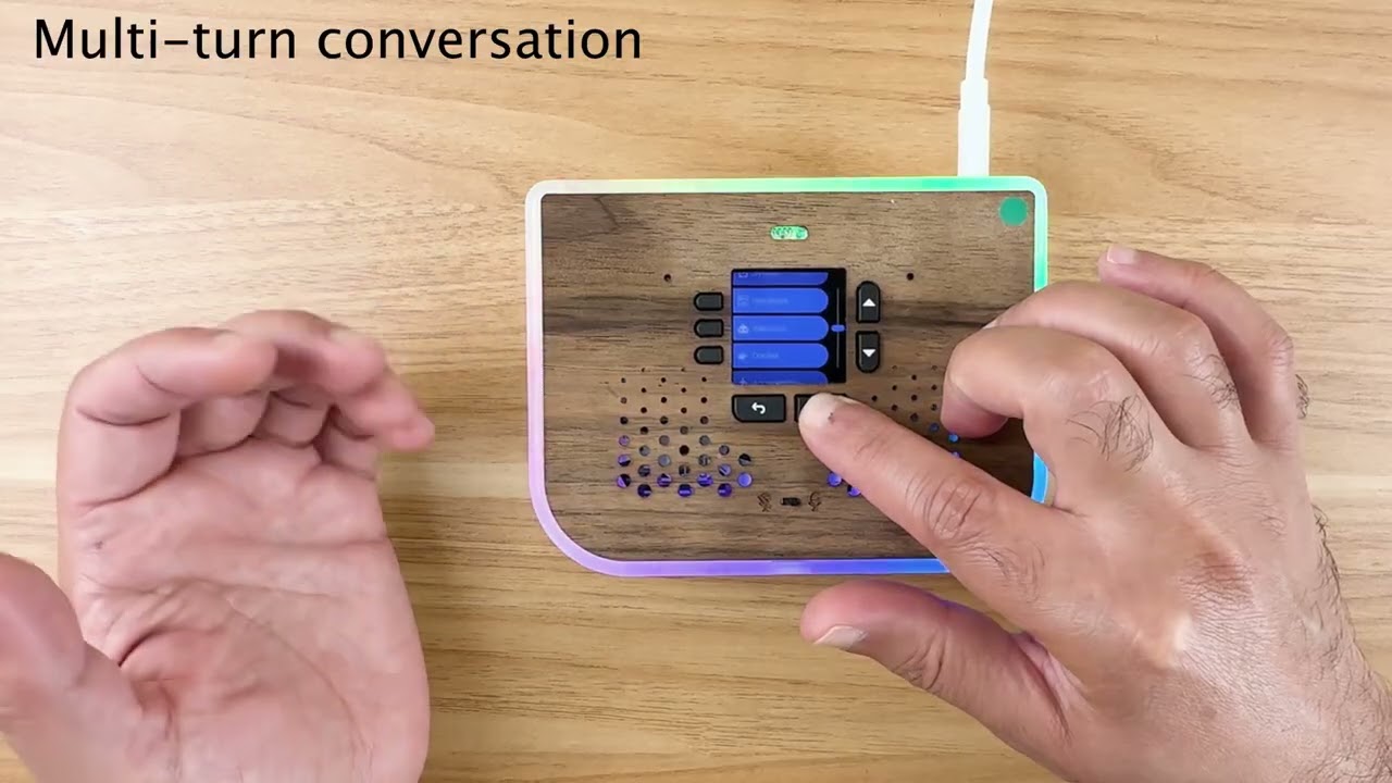
In this video, I demonstrate the voice and vision ai-enabled features of Ubo pod developer edition. I am going to demo other features in a separate video as part two.
- What is Ubo Pod
It is an open source hardware and software platform designed for developers and makers. The goal is to empower developers by giving them a set of polished tool...
 fluid grotto
This week I published my CircuitPython Z Machine emulator for the Fruit Jam. It can run Zork and other Z Machine games natively. It can run stand-alone or with Fruit Jam OS.
https://github.com/ZContent/CPZ_Machine/releases


GitHub
A native Z Machine for the Adafruit Fruit Jam running Circuit Python for playing Zork and similar games - ZContent/CPZ_Machine
brazen garnet
making a flex touch wheel with mrp121 touch sensor !

 sweet vapor
not exactly the hardest project but i used a matrix portal S3 and a 5mm pitch led matrix to make a remote wifi SPL display for the Front-of-House tent for festival sound, connecting to the websockets API endpoint in Smaart SPL (unconnected from any Adafruit sponsored thing/event sorry)
clever stone
brazen garnet
making a flex touch wheel with mrp121 touch sensor !
That’s pretty cool. I had not considered a touch wheel layout for discrete pads.
A while back I was able to create a touch wheel which could output a value from a range (e.g. 0..255 or 0..99). It had a simple I2C interface.
brazen garnet
clever stone
That’s pretty cool. I had not considered a touch wheel layout for discrete pads....
Thx I’ll report back when it’s actually working using an esp32
errant pasture
Got a simple but classic Fruit Jam game for you lovely people today: Pong! I'm working on writing a tutorial which will go through the process of writing the game from start to finish, but the game itself is ready to be downloaded and played. Enjoy! https://github.com/relic-se/Fruit_Jam_Pong/releases
GitHub
Tutorial code for how to make a simple pong game for the Adafruit Fruit Jam in CircuitPython - relic-se/Fruit_Jam_Pong
sacred timber
I just finished the build on my latest robot, the KRZ04. A few weeks ago I blew out (i.e., blue smoked) the STM32 I was using as a motor controller for four brushless motors, and at that point decided to go back to brushed motors, so it took me about a week to install a pair of ThunderBorg motor controllers and rewire and recode to incorporate those changes. This is powered by a Pi Zero 2 W, the chassis is all goBILDA, designed using OnShape.
 twin dagger
Here's a demo of my version of Bubble Universe for the Fruit Jam. It's running in 640x480 at 60 FPS and simulates over sixteen thousand particles. The code also runs on the PiCowBell HSTX DVI for Pico 2.
https://www.youtube.com/watch?v=d-laLSXaK-c

This is my version of Bubble Universe for the Adafruit Fruit Jam. It's running in 640x480 at 60 FPS and simulates over sixteen thousand particles. The code also runs on the Adafruit PiCowBell HSTX DVI for Pico 2.
Source code can be found here...
https://github.com/movievertigo/Adafruit-DVI-HSTX-BubbleUniverse
Music: http://www.purple-planet.com
twin dagger
twin dagger
Here's a demo of my version of Bubble Universe for the Fruit Jam. It's running ...
Source code can be found here...
https://github.com/movievertigo/Adafruit-DVI-HSTX-BubbleUniverse
grave nacelle
woah... that's pretty cool
twin dagger
twin dagger
Source code can be found here...
https://github.com/movievertigo/Adafruit-DVI-HS...
And here it is running on the PiCowBell... https://www.youtube.com/watch?v=ljmWIVI5Beg

This is my version of Bubble Universe for the Pico 2 + Adafruit PiCowBell HSTX DVI. It's running in 640x480 at 60 FPS and simulates over sixteen thousand particles. The code also runs on the Adafruit Fruit Jam.
Source code can be found here...
https://github.com/movievertigo/Adafruit-DVI-HSTX-BubbleUniverse
Music: http://www.purple-planet.com
sharp comet
twin dagger
Source code can be found here...
https://github.com/movievertigo/Adafruit-DVI-HS...
That is awesome! thanks for sharing.
fervent finch
Soon I shall have the greatest pumpkin of all time
Next up: hooking up a 4 watt neopixel + using homespan to trigger it as a strobe light
zealous eagle
👀
marble mantle
fervent finch
Soon I shall have the greatest pumpkin of all time
Next up: hooking up a 4 watt...
4 watt?
that hurts
brazen garnet
sacred timber
I just finished the build on my latest robot, the KRZ04. A few weeks ago I blew ...
Nice job! Is this running custom firmware?
sacred timber
brazen garnet
Nice job! Is this running custom firmware?
Thank you. Firmware on the Raspberry Pi Zero 2 W? There's an on-board ESP32 running a standard MicroPython distribution, but all it's doing is providing a system clock. The STM32H723 that-is-no-more was actually running a custom firmware build of MicroPython for the chip (since there was no compatible distribution I had to build my own). But I'm not sure what you mean by firmware... like, what's running the robot itself?
brazen garnet
sacred timber
Thank you. Firmware on the Raspberry Pi Zero 2 W? There's an on-board ESP32 runn...
Yeah, what controls the robot?
sacred timber
brazen garnet
Yeah, what controls the robot?
A robot OS I wrote in Python. I don’t have the repo for this robot public yet (work in progress) but its predecessors are, e.g., https://github.com/ifurusato/krz03-os GitHub - ifurusato/krz03-os: Operating System for the KRZ03 Robot
It uses an asynchronous pub-sub message bus, for an autonomous behaviour based robot.

GitHub
Operating System for the KRZ03 Robot. Contribute to ifurusato/krz03-os development by creating an account on GitHub.
brazen garnet
sacred timber
A robot OS I wrote in Python. I don’t have the repo for this robot public yet (w...
oh cool! thanks for sharing
brazen garnet
After seeing ipods online a lot, I became nostalgic for my ipod nano 3rd gen. I am in the process of making a mini mp3 player that suits my needs in the modern day, it has a 2" tft display, esp32 pico (for bluetooth & wifi), high end DAC, microSD, etc. My plan is to also add spotify capabilities too.
If anyone would like to collaborate let me know! nothing is final and am open to changes in any part of the project 🙂
I've made the schematics, pcb, enclosure (fusion360), and made a working prototype on a breadboard with a basic custom firmware (prototype for validating the idea only so far)


 north valve
The new clear NeoPot with clear knob and an LED noodle look great together.

 grave nacelle
brazen garnet
After seeing ipods online a lot, I became nostalgic for my ipod nano 3rd gen. I ...
grave nacelle
brazen garnet
After seeing ipods online a lot, I became nostalgic for my ipod nano 3rd gen. I ...
cool. You've probably already seen this, but just in case you haven't: https://www.crowdsupply.com/cool-tech-zone/tangara
brazen garnet
@grave nacelle hehe yeah I've seen it before, felt like it was too bulky and wanted to try my hand at making my own.
zealous eagle
I thought of this as soon as I saw the new ESP-NOW learn guide.
https://github.com/Airplane-Journal/ESP-NOW-Remote-Shutter/tree/main
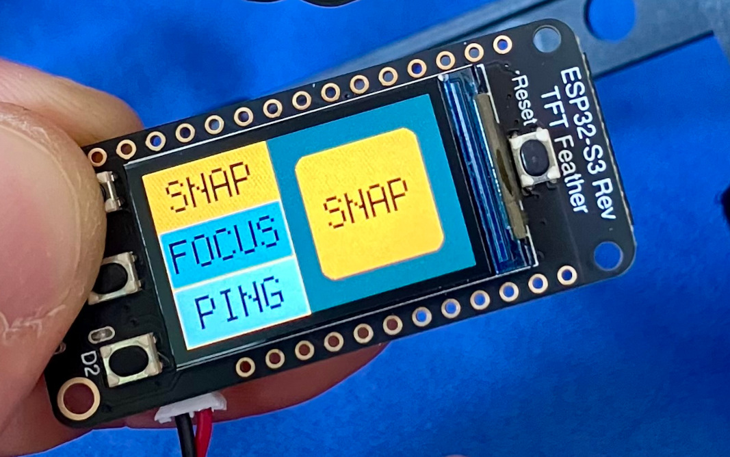
GitHub
Remote shutter button for Adafruit Memento with ESP-NOW - Airplane-Journal/ESP-NOW-Remote-Shutter
sharp comet
zealous eagle
I thought of this as soon as I saw the new ESP-NOW learn guide.
https://github.c...
Neat idea, and well done! Thanks for sharing.
zealous eagle
sharp comet
Neat idea, and well done! Thanks for sharing.
Thanks for the kind words!
fervent finch
fervent finch
Soon I shall have the greatest pumpkin of all time
Next up: hooking up a 4 watt...
 marble pilot
Oh, the trick or treaters aren't going to like this one...
Raspberry Pi Pico, Adafruit UDA1334 DAC for the audio, a PIR module, a strip of neopixels, and a powered speaker.
 sacred timber
marble mantle
sacred timber
marble mantle
Great job, I love the spider-ishness of it. A bit creepy to see a bunch of them approaching you on the carpet 😱
cunning lava
marble mantle
I could never make the mg90 version to work properly, they were too heavy, what battery did you use?
gusty shard
Neofetch for Retro Computers
(Claude Desktop made this for me)
https://claude.ai/public/artifacts/3a603908-1c5b-4ff3-b3dd-475ad6be97d7

Claude
Explore vintage computing with an interactive simulator featuring classic mainframes, minicomputers & early PCs. Learn about PDP-11, VAX, IBM 360, Cray-1 & more.
marble mantle
cunning lava
I could never make the mg90 version to work properly, they were too heavy, what ...
same as you, CR123A
I haven't fully tested it yet, but it certainly can move all legs, up and down, even at once, there doesn't seem to be any problem with battery current.
Or did you have problems that the servos are so heavy that the whole robot is unstable and tips over?
cunning lava
marble mantle
same as you, CR123A
I haven't fully tested it yet, but it certainly can move al...
no, basically when it starts walking, the battery voltage dips and the microcontroller browns out, maybe I just have poor quality battery
marble mantle
so far it seems ok.
https://photos.app.goo.gl/8rGd4W54MNSjR9Zc8
(this is a very first attempt in creating a gait for it, so it is very unsteady yet - like a kid learning how to walk)
 marble mantle
just in case, maybe I should add a bulk capacitor, like 330 uF to schematics
sly rampart
cunning lava
no, basically when it starts walking, the battery voltage dips and the microcont...
That does sound like a battery issue that it's not able to handle the discharge rate spikes as expected.
If you're using a high-capacity battery model that might be it, higher 'density' is done with lower peak charge/discharge rates, so like for 18650 cells looking at Samsung specs?
- A 20S only has 2000mAh but allows for a 30 amp (dis)charge rate.
- A 35E has 3500mAh capacity, but only supports an 8 amp (dis)charge rate.
cunning lava
marble mantle
so far it seems ok.
https://photos.app.goo.gl/8rGd4W54MNSjR9Zc8
(this is a very...
in my code, I make the whole robot tilt to the side (by making legs on one side move higher than on the other side) before I raise a leg on the opposite side, so that the weight doesn't rest on that leg
marble mantle
it is learning
https://photos.app.goo.gl/Jh3jYMGuY537vvao6

 supple mortar
I made a little an android app for bridging MQTT and BLE with the android as the bridge. Maybe it's useful to somebody 😉 http://wildq.com/mbb/
And if anybody want to be in the google play closed testing group I'm looking for 12 people.
 terse creek
My boss brought his (very expensive) E bike to my classroom the other day asking for help unlocking it. It seems that he set a password on the controller panel so nobody could use it if it got stolen, and then he promptly forgot the password. He wanted to know if we could crack it, and naturally, I accepted the challenge. The solution? A QT-py module running circuit python, a relay board for the power button and regular gpios for the other buttons, plus a light sensor to detect if the screen powered off, and to alert when the password was found.
We're up to 680 now, testing about 6 guesses per minute.
sand grotto
terse creek
My boss brought his (very expensive) E bike to my classroom the other day asking...
Super cool, just a few weeks away from success ⏲️
terse creek
Yup! Got up this morning and saw it was found. Had to rewind a few digits and let it play through so I could get the video. 🙂
sand grotto
terse creek
Yup! Got up this morning and saw it was found. Had to rewind a few digits and le...
No one is safe! Congratulations, impressive (and useful)❣️
terse creek
😁
nimble sapphire
Hi all! Work is holding me back and I miss seeing you on Wednesdays ... but have hope! The newest iteration of Rolling Thunder is being made! 🙂
fervent finch
Zolgar the All Knowing is about complete. Just in time to tear it down and rebuild it lol
 broken sandal
I've made a CC scene switcher for my favorite synth: the Beetlecrab Audio Tempera. The left 8 keys on the Macropad are CC values that I can edit by holding a key and turning the encoder(which also immediately sends those values so I can see what I'm doing.) Those are stored in one of four "scenes" indicated by the right four keys. Hitting one of the scene keys switches to that scene and immediately sends all the CC values stored there. Almost 200 lines of Circuitpython that (after a few days of cosmetic faffing about) worked flawlessly first try when I plugged it into Tempera's host jack!
In this video, I'm just sending various relative X and Y values to the blue emitter to make it emit sound from a different part of the "canvas". Neato!
broken sandal
This is a better indicator of what it can do: https://youtu.be/w3wiegcifi4

Just a proof of concept tonight with one of my percussive canvases.
I've been coding an Adafruit Macropad. It's a nifty little device with twelve keys, a clickable endless encoder, and a screen. It also mounts directly to Tempera's USB host jack and sends CC messages like a pro with a little Circuitpython.
I designed this "CC Switcher" to have...
broken sandal
Much cooler.

 hollow sigil
here's my daughter's halloween costume, and I'll post the other images here as well so you don't have to click through a few times to see them


 red wolf
Ada fruit green led sequins for the win.
 swift nexus
Had a ton fun at Hackaday Supercon this year. Got a lot of excitement over my nOOds designs. Folks kept asking if it was EL wire and were surprised they were not only LEDs, but also powered at ~3V.

 clever stone
Each year I release a new eChallengeCoin - an electronic challenge coin.
Starting in 2024, the eChallengeCoins include a custom text adventure game. Hidden away inside a 47mm*7mm “coin” is a 32bit processor, flash memory, sound, addressable LEDs, a touch sensor, and USB. … and it supports CircuitPython !
clever stone
Verified CircuitPython 10 is performing well on the 2026 eChallengeCoin 🤩
 placid ledge
My latest CircuitPython creation: human tracker using the Grove Vision AI V2 board. My library (with this demo) is at: https://github.com/bikeNomad/CircuitPython_grove_vision_ai_v2

GitHub
CircuitPython support for the Seeed Studio Grove Vision AI V2 module. - bikeNomad/CircuitPython_grove_vision_ai_v2
nimble sapphire
 regal maple
Here’s something I’ve been working on, a gas lamp effect running on a QT Py CH32v203 board. It’s using Arduino and fixed point math to run a hooks law based fire simulation using a cell automation on 12 nodes and other enhancements driving 9x2 neopixels. Big props to Adafruit for making this chip so accessible.
grave nacelle
This is a LoRa thermometer I'm building to monitor the temperature at a greenhouse about 500m away. I don't have a clear line of sight (buildings, trees, etc.), but it pretty much works. I used a Nordic PPK2 to get the battery usage down for the sensor. Now I'm working on tuning the radio settings to trade battery life against signal quality. Work in progress code at:
https://github.com/samblenny/lora-greenhouse-monitor

 sacred timber
grave nacelle
This is a LoRa thermometer I'm building to monitor the temperature at a greenhou...
sacred timber
grave nacelle
This is a LoRa thermometer I'm building to monitor the temperature at a greenhou...
Nice job. Since it's a greenhouse have you considered a solar panel for charging the battery?
grave nacelle
sacred timber
Nice job. Since it's a greenhouse have you considered a solar panel for charging...
Indeed I have considered that. There are some pros and cons. So far, I've come down on the side of just running off of a small LiPo cell. If my estimates are accurate, I should be able to run for about 2-4 months on a 400 mAh LiPo cell, sending a report with battery voltage and temperature every 20 minutes. If I were to do solar charging, then I'd need to add a lot of parts and complexity to the sensor. For example, I'd need to make sure not to charge (or not to overcharge) the battery when it was outside of the optimal charging temperature range for LiPo chemistry.
I'm expecting the sensor to potentially be exposed to temperatures in the range of 0°F to 100°F, so the charging setup would need to be smart enough to understand when it was acceptable to charge, and at what rate. Normally the temperature would be more controlled, but the main point of the sensor is to get early warning if a door gets left open, if the heater or vent fans fail, etc.
detailed power anaysis at: https://github.com/samblenny/lora-greenhouse-monitor/blob/main/power_analysis/README.md
short summary version: about 22µA while in deep sleep, and each wake cycle uses about 125 mC of charge (for my current radio settings). Wake cycle lasts about 2.05 seconds. Wake cycle charge used would of course go up if I did stuff like increase the LoRa radio spreading factor, etc.
glad roost
@sacred timber I think we may have rate limited this channel years ago due to it accidentally being used instead of #live-broadcast-chat for the Show and Tell video show.
we could probably turn that off
I will inquire later this week (the person to ask is out right now0
ok, I found the discussion. It wasn't where I was expecting it. Last May we rate-limited to channel because some people were using it as a frequent running status report of the projects they were working on or what was up in their workshop, instead of using it to announce a finished project.
I think it was just an attempt to do it in an automatic way, but it's not really very effective. I'll discuss it with the moderators. I agree it would be nice to be able to discuss a presented project (especially in a thread).
nearly all will, but a few won't. We have about 40k subscribers
this could be discussed in #help-with-community without limiting
I'm happy to hear your perspective, no problem.
polar eagle
I made Dice of Sending , for when your dungeon master wants you to roll online but you dislike digital dice. This was a goofy little project I worked on. It's fully open source and you can check it out here: https://github.com/TravisBumgarner/dice-of-sending
sudden sail
regal maple
Here’s something I’ve been working on, a gas lamp effect running on a QT Py CH32...
This is one of the coolest projects I’ve ever seen! I want to replicate this with Circuit Python. Love the resistor as the gas level!
 cursive oak
regal maple
Here’s something I’ve been working on, a gas lamp effect running on a QT Py CH32...
cursive oak
regal maple
Here’s something I’ve been working on, a gas lamp effect running on a QT Py CH32...
Interesting that you chose a different approach vs https://learn.adafruit.com/ooze-master-3000-neopixel-simulated-liquid-physics

NeoPixels are beautiful. Let’s use them in something gross and icky!
regal maple
sudden sail
This is one of the coolest projects I’ve ever seen! I want to replicate this wit...
Thanks! You can certainly do this with Circuit Python though you'll need a much faster chip. If you use one with a floating point module, like the M4, and Python takes advantage of it that could save you from having to use fixed point math. Here's a nice explanation of the algorithm I used, the article is using it for a 2D water simulation but the algorithm is the same. https://code.tutsplus.com/make-a-splash-with-dynamic-2d-water-effects--gamedev-236t
For my flame simulation, each NeoPixel acts as a spring in a chain whose “resting” value is off. on each 'frame' I inject a random amount of velocity (representing gas) into the first spring at the bottom of the strip. That energy then propagates along the chain while naturally decaying, creating the appearance of a rising flame. The range and median of that random gas input (its min/max spread) determines how bright and flickering the flame appears. The brightness potentiometer affects the median of the injected gas value.
Each spring’s “height” above resting maps to the brightness and hue of its corresponding NeoPixel. You can imagine it like a rope lying on the ground: when you pick up one end and shake it, a wave travels along its length. That’s roughly what’s happening here.
A separate “master” spring, with its own tension and damping values, modulates the overall minimum and maximum additive gas levels over time. This produces the pulsing glow of the lamp.
At random intervals, I add a random burst of velocity to both the bottom spring and the master spring, creating a brief spark and extra wavering in the flame.
The guttering effect works by using an inverse, decaying sawtooth wave with a random depth and period to subtract velocity from the bottom spring, momentarily starving the flame and making it flutter.
If you have any questions let me know!

Code Envato Tuts+
Sploosh! In this tutorial, I'll show you how you can use simple math, physics, and particle effects to simulate great looking 2D water waves and droplets.
Note: Although this tutorial is...
sudden sail
regal maple
Thanks! You can certainly do this with Circuit Python though you'll need a much ...
I may! I’d love to try some physics modeling on these low power chips. My day job is analysis using big physics models, which I rarely have to program myself.
regal maple
sudden sail
I may! I’d love to try some physics modeling on these low power chips. My day jo...
That sounds like a cool job, big physics models are a real challenge!
sudden sail
regal maple
That sounds like a cool job, big physics models are a real challenge!
I can’t complain. 
 warm bolt
I've been enhancing the GurgleApps Word Clock recently. It's a 3d-printed kit made by a family in the UK based on a Pi Pico W and 8x8 RGB LED matrix. I've added a light sensor to it and made the MicroPython code automatically adjust the brightness with changes in ambient light: https://www.instructables.com/GurgleApps-Word-Clock-Assembly-With-an-Ambient-Lig/ - as part of that construction I decided to use 5.0V rather than the 3.3V supply and did some practical testing of that https://www.instructables.com/Testing-an-RGB-LED-Matrix-With-Different-Supply-Vo/

Instructables
GurgleApps Word Clock Assembly With an Ambient Light Sensor: The GurlgeApps Word Clock is a USB-powered open-source digital clock which shows the time as words in English. The letters in an 8x8 grid layout can be individually illuminated in any colour. This small desktop clock is a descendant of the multi-lan…

Instructables
Testing an RGB LED Matrix With Different Supply Voltages: Strips and grids of RGB LEDs are typically powered at 5V or 12V. In the absence of a credible datasheet these can be tested** to determine if the LEDs still work at lower voltages and to observe any associated effects on brightness, colour balance a…
I added some Halloween backgrounds but the rendition isn't great on an 8x8 display: https://www.instructables.com/Halloween-Pixel-Art-on-GurgleApps-Word-Clock/
And I've just finished some tweaks to the (PIO-based) jtouch library for a capacitive touch pad with just a wire and no external resistors: https://www.instructables.com/Add-Touch-Button-to-GurgleApps-Word-Clock-Using-RP/
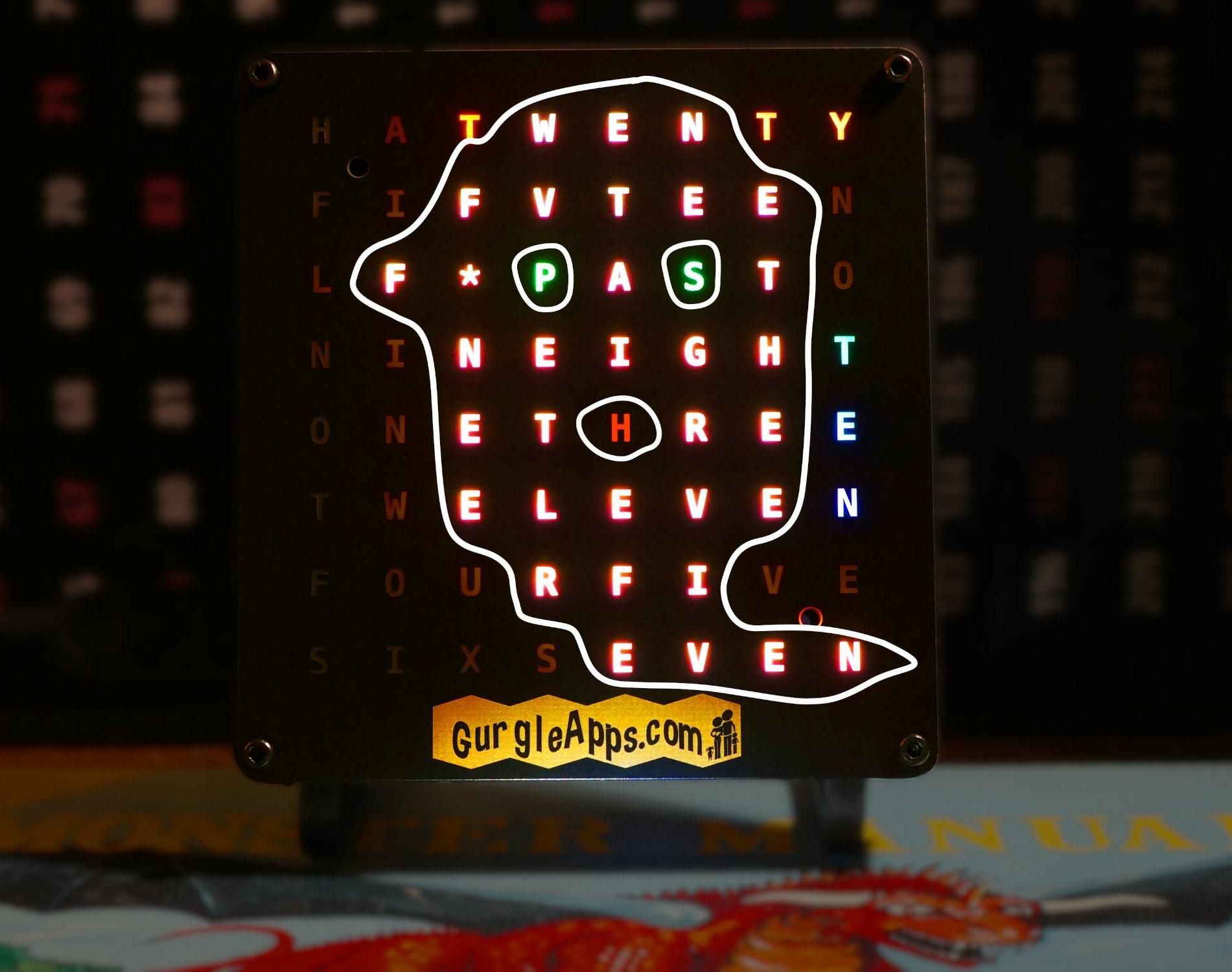
Instructables
Halloween Pixel Art on GurgleApps Word Clock: The GurlgeApps Word Clock is an open-source digital clock which shows the time as words in English. This small USB-powered desktop clock has letters in an 8x8 grid layout which can be individually illuminated in any colour.
This article shows how to…

Instructables
Adding a Touch Button to GurgleApps Word Clock Using RP2040/RP2350 Programmable IO (PIO): The GurlgeApps Word Clock is an open-source digital clock which shows the time as words in English. This small USB-powered desktop clock has letters in an 8x8 grid layout which can be individually illuminated in any colour. It can be controlled from…
errant pasture
Had the inspiration to create a sort of community app store for the Fruit Jam to (hopefully) dynamically install applications to an SD card directly from the device itself. I've got some of my games listed and a handful of great utilities from @grave nacelle. Are there any other apps out there that people wouldn't mind sharing with me to add to the database? Thanks! (here's the repo for the project: https://github.com/relic-se/Fruit_Jam_Store)
 short summit
errant pasture
Had the inspiration to create a sort of community app store for the Fruit Jam to...
short summit
errant pasture
Had the inspiration to create a sort of community app store for the Fruit Jam to...
Neat, I'll have to check it out. I've been wondering in the back of my head if something like circup bundle-add would work too, like circuitpython-fonts, then people could add games and apps similar to adding a library
errant pasture
short summit
Neat, I'll have to check it out. I've been wondering in the back of my head if s...
Dang, that's smart. 😮💨 Well, this could still be a companion to that! I was hoping to promote discovery by having it all in one place beyond the builtin-apps of Fruit Jam OS. (which this is designed to work with)
 weak dock
Holy crap.... after seeing so many amazing and complex projects in here I almost feel embarrassed to share mine 😅😅😅 but I'll do it anyway
It's a remix of @kindred urchin 's "Unicorn Hat with Moving Ears" project for the CPX.
The side-glowing optic fibre I ordered from a company here in 🇦🇺 had pretty much no side-glow unless in pitch darkness, so I skipped wrapping them together into a horn with a heat gun like she did, and instead left 10 individual bits to just end-glow.
I then modified her 3D printed CPX housing to allow this cheap little unicorn toy to be inserted in the centre (and held in by none other than a toothpick 😅) - its designed to 'pop up' in the air from that pink mesh acting as a spring, but here I just flick it.
I also added a 'collar' to the bottom of the 3D print so I could slide the whole thing tightly onto a wide hair band
I then ripped this little plastic unicorn off this fake braid thing and superglued it onto a potentiometer to be able to vary the light patterns. But when I put it back on and replaced the alligator clips with thin conductive thread, I must have had a short-circuit somewhere because the CPX made weird sounds at certain voltages, and at one point I saw a puff of smoke 🤦🏻♂️😅😅😅
So I was like "NOPE that's not going on a 4-year old's head at her birthday party" 🤣🤣🤣 and opted for shake-induced changing of lights using the on-board accelerometers instead

In the end the excitement over it wore off after a couple of minutes, she took it off, and was more excited by a 1$ thrift shop glowing plastic horn and an ugly icing cake 😅😅😅😅 but I still enjoyed the project, she and her folks appreciated the effort, and I had fun and learnt stuff along the way!

 grave nacelle
awesome
 blazing crater
So I still need to reprint the lid so it snaps on correctly, but this actually ended up looking pretty nice! This is a combination of air pressure, CO2, and particle sensor breakout boards that displays the info on the front panel. First time messing with 3d printing!
 grave nacelle
This shows an IRC bot I wrote for the Adafruit Metro ESP32-S3 with a 2.8" TFT display. It can join a local wifi network, connect to an IRC server (e.g. local Raspberry Pi hosted), and display the topic of an IRC channel on the TFT. This is meant to work as part of a system I'm building to monitor greenhouse temperature with LoRa sensors, but it could be used with any IRC bot that can set the channel topic. The numbers shown on the TFT lines 1 & 3 are current temperature, LiPo battery centivolts, 36-hour rolling min & max temperature. On lines 2 & 4 it's the node address and the timestamp when my serial-sensor-hub bot received the most recent LoRa packet for that sensor node.
Code: https://github.com/samblenny/irc-display-bot
Playground guide: https://adafruit-playground.com/u/SamBlenny/pages/irc-display-bot
 sand grotto
New pull requests just landed with ExpanderPin support added to Adafruit GFX & Adafruit ST7735 and ST7789 library, bringing initial support for the Arduino Nesso-N1 https://store.arduino.cc/products/nesso-n1.
It's an ESP32-C6 w/16MB flash under the hood, using an ST7789P3 display, and most of the buttons and some LCD pins etc are via I2C pin expanders. To make life easier the arduino team added displayWrite/Read helpers that accept an ExpanderPin argument, but we needed to add support for such arguments to our display constructors, etc.
Of course this is a precursor to board and display support in the Adafruit WipperSnapper firmware.
 sand grotto
blazing crater
So I still need to reprint the lid so it snaps on correctly, but this actually e...
sand grotto
blazing crater
So I still need to reprint the lid so it snaps on correctly, but this actually e...
Might be worth looking at extra holes for the CO2 sensor. That feather / ESP32 (and usually displays/power things) will generate a fair bit of heat which affects readings, so separation or yet more holes.
Otherwise most of the sensors have a temperature offset you can adjust to compensate for being in your specific enclosure/situation. You test recorded sensor temperatures versus real ambient temp after a settling period and at a few different real temps [cold day versus hot day] then stick in the average offset value or write more clever code to do a variable offset.
blazing crater
so there are vents on both sides - one for the CO2 sensor, the other for the PM2.5 sensor, but yeah I've noticed a temperature offset that increases as the thing is left on. My thought is to take readings from the BMP, the SCD40, and maybe from the feather if it has a temperature sensor and basically see if I can work out a calibration that figures out what the offset is based on the difference between the readings (since they're in different places)
sand grotto
blazing crater
so there are vents on both sides - one for the CO2 sensor, the other for the PM2...
think the esp32 does have a weak temperature sensor onboard, so maybe could track that too, I'd imagine it was +1.5c quickly / initially, and eventually 3-5c or so. Make sure you have an external temperature sensor when testing ambient versus BMP/SCD. Might be worth having the bmp keep natural temps, and the scd use adjusted/offset temp (Based on the BMP and your measured offsets).
blazing crater
any ideas how I could calibrate the pressure measurement to separate altitude vs weather?
sand grotto
Think you have to set (or ignore) an altitude, and then it will adjust only pressure. You also have a defined sea level pressure which can be altered if necessary. Varies a bit on the driver (which BMP?). Is this arduino or circuitpython or another? Worth jumping into those channels for help.
blazing crater
circuitpython and a BMP390
sand grotto
Have a look here: https://learn.adafruit.com/adafruit-bmp388-bmp390-bmp3xx/python-circuitpython#circuitpython-and-python-usage-3022491:~:text=For altitude and then you can adjust the expected sea level pressure to match your local weather report for air pressure nearby (or equivalent) at sea level. bmp.sea_level_pressure = 1013.25 making more accurate altitude readings / deltas.
blazing crater
thanks! this is sort of intended as a hiking buddy (detect wildfire smoke coming in) and the altitude idea was just a bonus, so maybe I'll just have it record the pressure when first turned on, and show deltas. I suppose the sorts of deltas from people walking up or downhill have a certain expected scale compared to deltas due to air movement, so the fancy thing might be to try some kind of smoothing function - like, accumulate only deltas over a 10 minute period that could realistically happen from hiking, and deltas larger than that are used to shift the baseline.
grave nacelle
A couple days ago, I uploaded a picture of a Metro ESP32-S3 running my irc-display-bot code and mentioned that it gets the summary reports from an IRC channel. To set those summary report channel topics, I'm using a hub server that I wrote in Go: serial-sensor-hub. It runs as a systemd service on a Raspberry Pi, taking sensor reports from my LoRa base station by USB serial, logging them to CSV files, updating the IRC channel, and plotting a 36-hour history chart on a web page. The screenshot here is an example of one of the 36-hour temperature charts from two of my LoRa sensor nodes. To make the chart, I generate a byte array of SVG source code in Go, then serve it with Go's usual net/http web server stuff. The sensors are in greenhouses about 500m from the base station, and they transmit a report every 9 minutes. There's enough resolution to see how the heaters cycle overnight and how the sunlight illumination changes during the day (clouds, shadows of buildings & trees, etc). Among other things, these charts are useful for fine tuning heater and vent fan thermostat settings in the greenhouses.
 grave nacelle
@sand grotto , you might like this one ⬆️ . It's part of my greenhouse temperature monitoring system for the irc-display-bot and LoRa temperature sensors.
sand grotto
grave nacelle
<@375674153203662851> , you might like this one ⬆️ . It's part of my greenhouse ...
Definitely do! Both the lora (the Arduino Nesso-N1 has an SX1262 and I have the same RadioFruit feathers as you), and project...
As soon as the irc thing came up weeks ago my mind was racing for a reason to make one of those DDL bots, where you request files and then it DMs them to you, but I use web clients the few times a decade I connect to an irc server these days, and not sure they have the level of support mIRC did for such shenanigans.
!ddl greenhouse1 36hrs csv
north valve
blazing crater
any ideas how I could calibrate the pressure measurement to separate altitude vs...
Hey, I needed something similar to assume a constant altitude. By setting an altitude you can calculate the weather changes independantly. Here is the BMP280 change that might help
https://github.com/somenice/Adafruit_CircuitPython_BMP280/commit/b754384f6ae660edd3ffdb58d83a97fcdb82342d
# Set fixed altitude otherwise set the the local bmp280.sea_level_pressure
bmp280.altitude = 695.0
Definitely do! Both the lora (the
 silver hemlock
An ongoing project.
Using an Intel Compute Stick (STK1A32SC) running NixOS with custom hardware.
It has GPS and a barometric sensor, and collects data through a text file. The stats are displayed onto the screens. All of these all driven by AdaFruit's FT232H.
If anyone's interested:
https://github.com/BnZel/NixOS_CyberDeck
GitHub
NixOS Cyberdeck running on a Intel Compute Stick (STK1A32SC) - BnZel/NixOS_CyberDeck
lucid bloom
I made the most automated room in my home assistant a little cooler. In addition to controlling everything in the room I got a free projector and I got a extra Chromecast and a wled sound reactive strip. I even made a esphome ir controller for the projector so it's automatable.
 outer musk
I made a 64x16 matrix LED display that is interactive. You can draw on it by typing in twitch chat. If you want to help test it, see it at twitch.tv/daverdavid
Still a work in progress, sometimes glitchy!
 clever stone
blazing crater
any ideas how I could calibrate the pressure measurement to separate altitude vs...
clever stone
blazing crater
any ideas how I could calibrate the pressure measurement to separate altitude vs...
If you decide to pursue the idea of getting altitude from the pressure sensor, you can take a page from the aviation world. Airplane altimeters have an adjustment for setting the current local barometric pressure. Then the altimeter shows altitude changes. However, at remote airstrips, pilots flip the script. They know the altitude of the airstrip so they adjust the instrument until the altimeter matches the airport elevation.
If you want to use it while hiking, create a UI where the user entered their current elevation … e.g. the altitude at the trail. That gives you the current barometric pressure without actually knowing its value. Now, your hardware will be able to calculate altitude by tracking the change in pressure.
Note: the “calibration” changes over time as weather conditions change so, at some point, it is going to need to be updated at a known location such as the summit or a tower.
blazing crater
Probably I should have included GPS in the design, then I could calibrate from an elevation map stored on device...
grave nacelle
For anybody following along with the LoRa greenhouse temperature monitoring system that I've been working on, I finally finished the Playground guide for the sensors and base station. An early draft got mentioned in the CircuitPython newsletter from last week (Nov 17), but that draft was missing a lot of important details on how to do the wiring and configure the settings.toml options. I added all that stuff to the Playground guide, so it should hopefully make a lot more sense now:
https://adafruit-playground.com/u/SamBlenny/pages/lora-wireless-greenhouse-monitor
sacred timber
grave nacelle
For anybody following along with the LoRa greenhouse temperature monitoring syst...
Would you mind if I copied your message over to the Personal Robotics server? I'm sure some of our community would be interested. You're of course also welcome to join, but in any case thanks, you've done a great job in also documenting the projec.t
grave nacelle
sacred timber
Would you mind if I copied your message over to the Personal Robotics server? I'...
sure. would be happy for more folks to see it.
 deep holly
check out my Rrealistic Flickering LED Flame Lamp
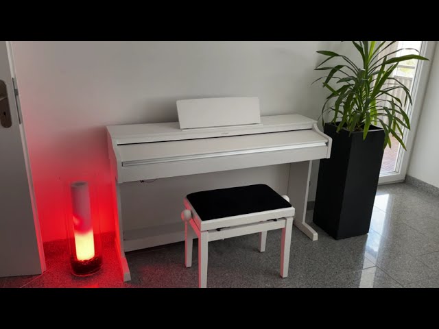
============HQ HD VIDEO============
Re-upload from my older video, now in High Quality
https://youtu.be/vdAvHDkBKbA?si=eKZX3lXiDbiTmHev
Led fire lamp basic code shared by RM Projects UK
RM Projekts UK Channel:
https://www.youtube.com/channel/UCvsi6E05hhZ3KHJTPSb4oCQ
============SOFTWARE============
Latest Code:
Original Code: https://www.yo...
 fading badge
deep holly
check out my Rrealistic Flickering LED Flame Lamp
https://www.youtube.com/watch...
fading badge
deep holly
check out my Rrealistic Flickering LED Flame Lamp
https://www.youtube.com/watch...
So good
 broken rain
made this for anyone that wants a case.
https://www.printables.com/model/1494609-adafruit-fruit-jam-case
 potent edge
learning plasticity (cad software) again, figured out how to make LED holders for the gamecube player ports.
What's really cool is that depending on the plastic used and LED used, if you drill the player port indicators on the front you can essentially have two tone lighting. The plastic being used for the player port lighting, and the port being lit with a different color entirely depending on LED color.
made after seeing people do gamecube mods by tearing apart the controller sheilding to hold the LED bulb, which i thought was weird. This is essentially non-destructive unless you wanna do the hole drilling thing. No glue/screws/etc. to hold it in, just the OEM hardware.
Plan to make a variant for custom CR032 holders (bigger hole) and then just posting the V1 online. wondering If i should make a neopixel variant. My goal was to hook them up to blue retro, which is a ESP32 thing to allow retro consoles to have bluetooth controller support. no clue if it supports RGB leds like that so for now simple ones will do.



GitHub
Multiplayer Bluetooth controllers adapter for retro video game consoles & computers - darthcloud/BlueRetro
grave nacelle
Latest update in my greenhouse LoRa + IRC temperature monitoring adventures... I made a 3d printable case for my irc-display-bot desktop display. The bezel attaches to the wedge shaped base using four 2-28x5/16" thread rolling screws.
This is meant to let a monitoring display blend in a bit better on a desktop, counter, or shelf in a room that is primarily used as living space (rather than a work area where bare PCBs might be more acceptable).
Playground guide with Blender and STL files:
https://adafruit-playground.com/u/SamBlenny/pages/3d-printed-enclosure-for-irc-display-bot


 hazy falcon
Nothing special, but i wrote a couple basic methods to translate stick position to a simple pan tilt mount (luckily I had a base esp32 handy to connect the controller to). I've been programming for a while but am new to microcontrollers. It's satisfying to see code physically do stuff! I have a robotics/opencv project planned and am splitting it into a lot of small projects. This was a fun one.
grave nacelle
Nice! I like those brackets. Looks like maybe some laser cut acrylic mixed with some kind of aluminum robotics construction set pieces, maybe?
 zenith frost
For the last few months I’ve been building a Cortex-M emulator from scratch, and I picked the Adafruit STM32F4 Express as the first board it should run on.
Technically it’s an emulator… but I keep calling it a simulator because it just sounds way cooler.
Demo:
https://simulator86.com
Simulate and debug microcontrollers using Rust online with Simulator86. Perfect for developers, students, and embedded engineers.
low pulsar
zenith frost
For the last few months I’ve been building a Cortex-M emulator from scratch, and...
Wow, very impressive! Some people seem to be using wokwi for CI testing too, I'm sure you've thought about it as well. Hope the project continues to gain traction.
hazy falcon
grave nacelle
Nice! I like those brackets. Looks like maybe some laser cut acrylic mixed with ...
Yes I have some parts from some makeblock robotics kits I purchased earlier this year. It's what inspired me to go further and learn more about microcontrollers. This is a pan tilt mount from them.
 ember cliff
Yesterday I cut out the pcbs for and assmembled my flight steering computer for model rockets 🚀


 hazy falcon
ember cliff
Yesterday I cut out the pcbs for and assmembled my flight steering computer for ...
hazy falcon
ember cliff
Yesterday I cut out the pcbs for and assmembled my flight steering computer for ...
That is so cool!
sand grotto
ember cliff
Yesterday I cut out the pcbs for and assmembled my flight steering computer for ...
That's amazing! Just curious as a cnc newbie myself, what caused the copper tearout on the flight controller pcb? Was it just an agressive plunge or climb milling or something (I'm bad with feeds + speeds), or did the workpiece come loose, or is it a challenging material?
sly rampart
sand grotto
That's amazing! Just curious as a cnc newbie myself, what caused the copper tear...
I think I see what happened, that large hole wasn't cut yet on the second 'all on the board' shot, but you can see the thin 'still attached' tabs of each board to the large copper panel, I'm betting the torque was at the right angle to snap the workpiece free since it was cut late in the program instead of early on and was 'off angle' to the last remaining 'support tab' left so the rotation just snapped the tab.
clever stone
Hackers (and IT admins) Who Travel Lite
For those who use an iPhone or iPad and find the need to connect to a serial/UART device, the options have been slim and expensive - until now.
Using just an RP2040 Zero it's easy to connect to a serial device using an telnet app. The Telnet2Serial is just 26mm^2
 sudden sail
ember cliff
Yesterday I cut out the pcbs for and assmembled my flight steering computer for ...
sudden sail
ember cliff
Yesterday I cut out the pcbs for and assmembled my flight steering computer for ...
I’d love to know more about this! Do you have a git or anything?
ember cliff
sudden sail
I’d love to know more about this! Do you have a git or anything?
Hey there! I do, the repo is at https://github.com/SandwichRising/model-rocket-flight-computer . Just a warning, the v1 code and most of that info is outdated, going to publish 8 months of progress soon 😁

GitHub
Servo-based flight control and data logging computer for model rockets - SandwichRising/model-rocket-flight-computer
ember cliff
sand grotto
That's amazing! Just curious as a cnc newbie myself, what caused the copper tear...
I made a last minute update to one of the cnc programs, but then didnt push it all the way thru the file process on accident, so the cnc didnt end up cutting that specific hole. So I just marked center on the finished pcb and hand drilled it with a smaller, then started sizing up. But I jumped sizes too far at one point and the drill bit blew it out
Also, just fyi the copper PCBs definitely aren't the easiest to work with, wood is easier. The tolerances for PCB is really tight, you have to cut thru top layer to make sure the copper is severed, but with a pointy bit any extra depth eats away your trace width so thats bad. And it forces you to find good feeds and speed or it absolutely shreds the edges of the traces lol. My machine just probes one point, so I reprobe Z to do each board's traces individually. But for the holes and cutting out the outlines I dont rezero Z between each board
sly rampart
ember cliff
Also, just fyi the copper PCBs definitely aren't the easiest to work with, wood ...
I wonder if setting up a clamped sandwich with a sacrificial layer of some other material like even just 1/4" plywood or a cheap thin acrylic sheet on top of the copper PCB layer would make it easier and allow for cleaner edges when cutting the traces? Same theory as clamping a piece of wood between two scraps for fine woodworking to get cleaner edges by avoiding chatter and less kerf in the 'middle' of a cut material instead of the surface.
ember cliff
Maybe, hmmm but I wouldnt want to run my pcb but thru all that tho
sly rampart
Yeah depends on the bit, if it's a specific PCB bit it's not meant for depth so yeah. Would be more if you have a generic thin side-milling bit, yeah.
brazen garnet

 brazen garnet
about done with my macro pad 🙂
 rigid lily
I wrote a web app that provides a logic emulator using an ItsyBitsy32u4.
This is useful for people wanting to try combinational and/or sequential
logic but that don't have access to design tools or PLD device programmers.
All they have to do is write the logic equations and use the app to flash
the microcontroller via USB.
The open source code is available at:
https://github.com/alexandrepal/SeqEditor


GitHub
SeqEditor is a CustomTkinter-based GUI that lets you flash a microcontroller with simple sequential/combinational logic - alexandrepal/SeqEditor
marble mantle
clever stone
Hackers (and IT admins) Who Travel Lite
For those who use an iPhone or iPad and...
Telnet!
I haven't used it in years...
Now, if it only supported gopher protocol, I could re-live the days of my youth 🙂
clever stone
marble mantle
Telnet!
I haven't used it in years...
Now, if it only supported gopher protocol...
Hah!
The reason for Telnet was "simplicity". There are lots of SSH/Telnet apps in the App Store. Also, a Telnet "terminal" is a lot like a serial terminal so the UX is comfortable.
If there is a better interface experience, I am definitely open to seeing what is possible.
grizzled siren
I’m working on a usb-c hub with dockable modules in the Framework expansion card format. We are also building some useful tool cards like a multimeter, power supply, esp32-s3 dev board (Xiao), Mini SSD (2TB), etc.
I would love to get your feedback, this is our website https://dockframe.com
DockFrame
DockFrame is a modular USB-C hub that accepts Framework-compatible Expansion Cards and custom Tool Cards. Dock once, reconfigure whenever.
grave nacelle
I've been working on an airgapped TOTP token with a bright screen that's easy to read in low light. This would be terrible for portable use, but it works great for my desk. Just got a 3d printed enclosure going for it today. Under the plastic there's an Adafruit CLUE, an I2C NeoKey keypad, a DS3231 RTC, and an I2C EEPROM for secret storage. I'm running a modified version of the latest CircuitPython beta, patched to support hashlib.new('sha1') (not usually available on CLUE).
sudden sail
https://youtube.com/shorts/sCjliKWMyYY?si=qjTxpdZ_BnoJYEmB
Finished my latest art project.

 lunar shale
ICD simulator for a friend's kid's science fair project. He came up with the idea and design. He and his parents were trying to do this with Snap Circuits and AI advice when they reached out to me. I save my Adafruit pink boards for special occasions, and this qualified. We did this entire project in a half a day.
 lucid bloom
My latest project in collaboration with the French Resistance
https://teamaugust.us/
VIVE BARENTON SUR SERRE !
VIVE LES JEDBURGH !
VIVE LA FRANCE !
sly rampart
lucid bloom
My latest project in collaboration with the French Resistance
https://teamaugus...
So the link doesn't just look like just a random "Trust us, click it!" URL when posted into Discord, etc, adding the extra HTML tags to support an OpenGraph preview image to the homepage at least would be recommended! opengraph.xyz is the site I usually use for checking those.
lucid bloom
ok thank you
that html for that page is generated with a python program, i will rewrite it to include what you said but not til tomorrow
https://teamaugust.us/test22.py
https://teamaugust.us/sources.html
this page does better or not lol
I vibecoded it and vibe translated it, I saved all my versions so i can show the progression, python, js, html, css in one file and building from a dir of files
when i do vibe coding I only do it as an iterative thing because over time it changes less and less and I understand it more and more. Now I have an example i can share to show people how.
lucid bloom
You can prompt it for a list of my prompts so you don't have to scroll a lot
https://gist.github.com/matt-desmarais/96de500de1bf5475c88ecd47c2a8385c

Gist
https://teamaugust.us prompts. GitHub Gist: instantly share code, notes, and snippets.
polar eagle
👋🏻 Just launched the first episode of my new podcast - Happy Making!
For years I’ve wanted to start a podcast to interview curious and passionate makers in the depths of their creative pursuits.
I would love any feedback, a rating, and if you know anyone would would make a great guest, please let me know!
 queen epoch
some friends of mine wanted to relaunch a project we worked on years and years ago, interactive 'drums' that light up and play a sound when you hit them. our original implementation was on a teensy with an adafruit lisd3h accelerometer breakout, on a custom PCB that handled audio playback with a teensy audio shield and a very basic LED tape driver with logic-level FETs and a GPIO expander, but this new version uses a wiznet rp2040 ethernet board and another lis3dh breakout, and sends OSC to a central lighting and audio controller (enttec S-Play and a mac mini running QLab, which send sACN and Dante back to each individual drum for lighting and audio). these are installed at the denver zoo for their zoo lights installation, which runs through the beginning of January if you're in the area: https://www.instagram.com/p/DSGimgciSeI/


The Drum Circle Installation is back up and running, its new brains are kicking it into gear at @denverzoo Zoo Lights! We are so happy to bring this fun interactive back and clear off the dust. We overhauled all the inner workings and have everything networked and talking to each other. This is the very beginning of reintroducing interactivity i...
Instagram
lucid bloom
https://chatgpt.com/share/6940dc36-a694-800b-936c-4d8a4fc9e91b
https://gist.github.com/matt-desmarais/71b3a15ec578dd363468e13eb03901ae

Gist
Precision-bounded guessing game demonstrating logarithmic convergence under explicit measurement resolution. - code.java
I'm curled up with some hot cocoa, tonight was a great night I got a lot of important things done
lucid bloom
learned new thing by bashing me head into chatgpt for a couple days, now have a way to calm people in an emergency
http://mattthemaker.org
 subtle pagoda
wdym by bashing ur head into chatgpt
lucid bloom
Basically I tell it what I want, verify solution and then tell it what it did wrong. over and over again until solution works
I could refine my approach but for now it works
I used my approach to make an album yesterday
https://aisonggenerator.io/my-songs/albums/648ba99e-31cf-4a94-a82f-8326efc72c13

Discover and listen to AI-generated song albums
lucid bloom
I paid for it so Commercial License & Unrestricted Usage

AI Song Generator
AI Song Generator is a cutting-edge AI-powered tool that lets users create original music effortlessly. Anyone can generate royalty-free music.
grave nacelle
If you're wanting to have a general discussion about using AI chatbots, the main #show-and-tell channel isn't really the right venue for that. You could start a thread or perhaps use #general-chat.
 worldly surge
AI generated music 
 loud crane
i made a vercel like cli tool for coolify, which is a self hosted alternative to vercel and netlify and heroku. it's a one-command deploy tool, and you just run cdp in your project directory and it auto-detects what type of website it is and deploys it.

GitHub
coolify deploy tool. Contribute to dropalltables/cdp development by creating an account on GitHub.
fringe vault
My current work-in-progress, a vertical mouse to go along with my custom keyboard...
https://codeberg.org/whitelynx/lynx-mouse


Codeberg.org
This is my custom mouse design, heavily influenced by the Zalman FG-1000 FPSgun mouse.
errant pasture
Just finished porting the Pac-Man game recently featured in the newsletter to Fruit Jam! Performance isn't completely stable, but it's definitely playable. A download is available in the comments of the PR. https://github.com/scarolan/pac-wio/pull/1

GitHub
I've decided to port your rendition of Pac-Man on the Seeed Wio Terminal to the Fruit Jam in order to add this arcade classic to the roster of games on that platform. I tried to maintain co...
sly rampart
errant pasture
Just finished porting the Pac-Man game recently featured in the newsletter to Fr...
Nice job! 😄
twin musk
If anyone is interested, here is a quick (under 5 min) look at some of the projects from my CircuitPython Physical Computing course. Thanks to @glad roost @balmy lake & @subtle delta whoh all stopped by to encourage my students.
https://bit.ly/physcomp-projects-fall2025

Final projects and assistive tech projects for Prof. John Gallaugher's course: Physical Computing: Art, Robotics, and Tech for Good at Boston College.You can...
low pulsar
twin musk
If anyone is interested, here is a quick (under 5 min) look at some of the proje...
This looks like an amazing course ❤️
twin musk
low pulsar
This looks like an amazing course ❤️
Thanks so much! It's super-fun to teach. If anyone wants at it - I teach it "flipped" so all the lessons are online at https://bit.ly/circuitpython-school. There are a few more I added this semester at https://bit.ly/pixelblaze-school And since it's end-of-semester, all the slides I present each week, which are mostly challenges & solutions for applying the prior week's video lessons, are in the course open Google Drive at: https://gallaugher.com (sorry for the vanity URL). All are welcome at it. It takes so much work to create the lessons I'm really excited when other educators or indepenedent learners use what I've created. Cheers!

YouTube
A Playlist containing all of the lessons and projects in Prof. John Gallaugher's course: Physical Computing: Art, Robotics, and Tech for Good.

YouTube
Tutorials for using the ElectroMage PixelBlaze! A magical and easy-to-use LED light controller. Buy PixelBlaze here: I teach with PixelBlaze as part of my mo...
lucid bloom
sly rampart
So the link doesn't just look like just a random "Trust us, click it!" URL when ...
fixed, thanks
http://teamaugust.us/

Team Augustus
Discover the history, reports, and archival main pages of OSS Jedburghs Team Augustus.
Most everything is AI in that project from image editing to translations to the site itself.
grave nacelle
If you're hoping to connect with an audience that enjoys hearing about album announcements for Gen AI music or Gen AI website launches, that isn't what people usually come here for. If there's some kind of aspect to your project that involves DIY electronics, robots, cosplay, custom MIDI controllers, custom synths, hardware fabrication, etc. people here would probably be interested in hearing about that part.
sacred timber
grave nacelle
If you're hoping to connect with an audience that enjoys hearing about album ann...
Judging by what I've been reading and what I've seen recently across several servers, we have entered the age of generated AI slop, people using generated AI text to participate in discussions rather than actually thinking and writing for themselves. As theoretically-sentient humans we either reject this or welcome it. I know how I feel about it.
grave nacelle
[edit: the post this was responding to seems to have been deleted]
Are you human? All those emoji bullet points look a lot like they might have come straight out of ChatGPT. Your project sounds kinda interesting, but I'm scared to click that link because it smells like the sort of thing that might be part of a holiday, mods-on-vacation, bot-fronted malware campaign. If it were just that one, I wouldn't be as worried, but in the last couple weeks there have been several marginally off topic posts clearly aimed at driving traffic to a link that's a bit out of the ordinary for this channel. Not quite spam, but kinda sus.
I'm posting this to see if the definitely-humans around here think I'm being too paranoid and need to chill out.
sacred timber
grave nacelle
[**edit**: the post this was responding to seems to have been deleted]
Are you ...
The other possibility is that we've entered the era where actual humans no longer write their own code or their own textual copy, so what they're presenting is generated AI text, which of course smells exactly like generated AI text. What's behind that, a human or an AI, is therefore impossible to tell.
This might (if they're smart enough) be a lesson to those creating content using AI, i.e., if what you create smells like AI, and your target audience is not AI but human, you may very well be pushing people away. I'm sure I'm not alone if finding the whole AI enterprise at this point stinks (and I have a background in a subfield of AI myself, not LLMs but KR/ontologies).
So no, not paranoid at all.
sly rampart
grave nacelle
[**edit**: the post this was responding to seems to have been deleted]
Are you ...
I'd normally counter-point that some of us (like me) enjoy finding Just The Right Emoji when building lists of items and even have a few Discord servers I've joined JUST for the emoji, but the glaring give-away is that they DIDN'T pick emoji from the emoji picker for that list:
Not properly generating ⚙️ is a specific flaw that I see happen a lot because the gear unicode (WITHOUT the Emoji modifier) existed for around a decade before being added as an official Emoji to unicode, and it's actually really hard to trigger that in Discord since it wants to auto-convert.
lucid bloom
I made a Pi Zero E-ink display to tie in with my Cape Cod Bridge Traffic app, took a few hours and came out pretty nice. I'm going to test it for a while and then potentially see if any local businesses are interested for tourist season.
https://sisosig.info/
https://github.com/matt-desmarais/SISOSIG-Sign/


Stay updated with live Cape Cod bridge traffic, delays and travel times to plan your travel efficiently.

GitHub
SISOSIG Cape Cod Bridge Traffic E-Ink Display. Contribute to matt-desmarais/SISOSIG-Sign development by creating an account on GitHub.
 kind gyro
lucid bloom
I made a Pi Zero E-ink display to tie in with my Cape Cod Bridge Traffic app, to...
kind gyro
lucid bloom
I made a Pi Zero E-ink display to tie in with my Cape Cod Bridge Traffic app, to...
why do you use JPEG and not PNG or other raster graphic files?
lucid bloom
Cuz it's not just for me, it's applicable to sets of images with the dates pretending the file names. There are a lot of unknown stories of the OSS in WWII and I want to help bring them to light, people can send me their files already dated and I'll be able to run the script and have the timeline page done. There are 116 people in the book of honor and I've only shared the story of two so far.
grave nacelle
wait, what??? So are you using a project about displaying Cape Cod bridge traffic as a trojan horse to deliver stories about WWII? I'm so confused.
sacred timber
grave nacelle
wait, what??? So are you using a project about displaying Cape Cod bridge traffi...
Wasn't one of the major battles of WWII fought on the Cape Cod bridge? 🤔 I think it was in the 1957 movie The Bridge on the Canal Cape Cod with Alec Guinness.
lucid bloom
grave nacelle
wait, what??? So are you using a project about displaying Cape Cod bridge traffi...
Sorry I've done so many projects recently it's hard to tell them apart. Like over a dozen in 2 weeks, they were supposed to last all winter so now I have to figure out what to do for the rest of the winter.
lucid bloom
lucid bloom
fixed, thanks
http://teamaugust.us/
@sacred timber
I have been in contact with all sorts of individuals and organizations related to that project, mainly the people he tagged. I'm probably going to France this summer to meet some of my new friends.

 lucid bloom
I'm probably on another watchlist now for talking to a foreign intelligence service 🙄
lucid bloom
I had to upgrade the sign to a pi zero 2, trying to work on a zero w brings back painful memories and it seems they are both $15 now so might as well use the better hardware
 vocal wave
Created a SaaS with the power of simple arduino sensors
 grave nacelle
This is my initial prototype for a printable Morse code straight key using flexure movement and a Chery MX compatible key switch. A lot of the printable straight key designs use DIY stainless steel switch contacts (chromium oxide film on stainless is worse than brass, nickel, gold, etc.) and come with warnings about how easy it is to twist the lever off by accident. I want to see if I can make one that solves both of those problems.
Main issue with using a keyswitch is that they have a lot of pre-travel before the contacts activate, so I'll need to figure out a good adjustment mechanism with a set screw or something. (this design includes a set screw hole over the switch plunger, but it's hard to see)
The flexure movement for this prototype ended up pivoting around its center rather than the straight up and down motion I was hoping for. So, I'm gonna have to work on constraining the motion to the right directions.
 low pulsar
grave nacelle
This is my initial prototype for a printable Morse code straight key using flexu...
low pulsar
grave nacelle
This is my initial prototype for a printable Morse code straight key using flexu...
Very cool! (I've been doing some experiments with semiautomatic bugs too https://github.com/kbsriram/3d-printed-cw-bug). The cherry switch is a neat idea. I went down the magnetic reed switch path, it decoupled the switch closure detection from influencing the other components. Good luck, love to see how it evolves 👍🏿
grave nacelle
woah... the demo video for that bug is really cool
grave nacelle
low pulsar
Very cool! (I've been doing some experiments with semiautomatic bugs too https:/...
Just printed my rev2 Morse key. Haven't wired it up yet, but the set screw adjustment seems to work well. It also pivots properly around the hinge without any noticeable flop or flex in the base. It's possible to twist the lever a few mm sideways out of plane from the base if you torque on it pretty hard, but it seems fairly robust. This could probably survive getting stuffed in a bag or pocket.
 sly rampart
grave nacelle
Just printed my rev2 Morse key. Haven't wired it up yet, but the set screw adjus...
sly rampart
grave nacelle
Just printed my rev2 Morse key. Haven't wired it up yet, but the set screw adjus...
Well done, and yeah that looks MUCH more like what I'd expect a telegram straight-key to look like also for layout and what part tilts where.
gusty shard
Pocket PDP-8
grave nacelle
Got a code practice oscillator working nicely:
https://github.com/samblenny/fruit-jam-code-practice-oscillator
Main noteworthy item here is that the Adafruit TRRS Jack Breakout Board slots into the Fruit Jam GPIO header very conveniently. Just gotta be a little careful about pin alignment to avoid shorting the 3V rail (Sleeve should go to GND or A1, but not 3V).

 low pulsar
grave nacelle
Got a code practice oscillator working nicely:
https://github.com/samblenny/frui...
low pulsar
grave nacelle
Got a code practice oscillator working nicely:
https://github.com/samblenny/frui...
Very cool!
 obsidian wind
sly rampart
Well done, and yeah that looks MUCH more like what I'd expect a telegram straigh...
grave nacelle
obsidian wind
sly rampart
Well done, and yeah that looks MUCH more like what I'd expect a telegram straigh...
grave nacelle
Wrote a guide for the code practice oscillator:
https://adafruit-playground.com/u/SamBlenny/pages/fruit-jam-code-practice-oscillator
gusty shard
Now I must build one!
 toxic sierra
Hey everyone! 👋
I made an open-source project called EmbeddedController. It’s all about messing around with microcontrollers — buttons, LEDs, and other stuff — and learning how hardware and code talk to each other. I’m 16 and learning step by step, and you can contribute as well. Would be happy if you ⭐ it!
https://github.com/CoreControlLabs/EmbeddedController

GitHub
Contribute to CoreControlLabs/EmbeddedController development by creating an account on GitHub.
grave nacelle
gusty shard
Now I must build one!
If you do, I'd love to hear how it goes. The one main problem I'm aware of with my rev2 straight key design is that it needs a limit screw to reduce the distance the key can travel on the other side of having activated the switch. The current set screw lets me dial in the switch activation point nicely, but it can be tricky to avoid a little bit of unintended latency when I lift my hand to stop the tone. It's still way better than the regular mini tactile buttons though.
grave nacelle
I made an AU file player demo that loads 8kHz 8-bit µ-law encoded samples and converts them to an audiocore.RawSample with 16-bit LPCM. The AU file plays in a loop, alternating with a 16-bit LPCM WAV file for comparison of audio quality. This might be of interest to folks who want to make games with lots of audio samples. Because µ-law does companding, it sounds better at low volumes compared to 8-bit linear PCM (the only currently supported 8-bit encoding for audiocore.WaveFile). If people like this, maybe we should consider adding WAV file µ-law decoding to audiocore.WaveFile.
code: https://github.com/samblenny/fruit-jam-au-file-player
video demo: https://youtu.be/FiIHJt8b-Jc

This demonstrates the audio playback quality for an 8kHz 8-bit µ-law encoded AU file alongside of an 8kHz 16-bit LPCM encoded WAV file on the Adafruit Fruit Jam. Basically, they sound about the same, which is the whole point (demonstrating that my CircuitPython µ-law decoder code works).
lucid bloom
I wrote this over a few days in November, finally out so I can share it. I hope it's relatable.
lucid bloom
I have achieved an objective a few days in the making. I have a cm4 with a carrier board and an sdr. My goal is useful radio stuff. I have a scanner I wrote that uses a chirp csv file to scan frequencies. I also installed "intercept" which looks pretty promising
https://github.com/smittix/intercept
They can both run at the same time with rtl_tcp (that was the objective) I still have to add more hardware and maybe more software that takes advantage of rtl_tcp.
 worldly surge
The latest release of WLED-MM has given hugely improved performance on the S3 Matrix Portal - driving 4 64x64 panels with layered segments at around 40fps here
worldly surge
lucid bloom
I have achieved an objective a few days in the making. I have a cm4 with a carri...
rtl_433 is great fun in my experience - there's so many assorted sensors and devices floating around the air
lucid bloom
yea there are, I used to use rf outlets and sensors but now I have better stuff. I have an sdr (rtlamr) reading the water, gas and electric meters
when my parents go away I use a lot less water, gas and electricity. My dad said if i could prove it he would pay me the difference so I did.
worldly surge
I did the same via rtl_Sdr on home assistant, although I've moved over to using Open MQTT Gateways running on lilygo boards - much more reliable.
lucid bloom
nice, there is data everywhere if you know how to look
I have done 5 home assistants with 4 different use cases since 2020. It is my jam its what I do for fun and whatnot. My personal one, a food pantry, a computer museum and some family properties. It is so powerful and useful, can literally make/do anything you want and not break the bank
lucid bloom
Here is a project my friends and I worked on over a couple years, I decided it was good enough to document and share. All hail MightyMac! it has been bulletproofed in terms of character input, you can put in another languages characters and it will get mapped to the right one so it doesn't crash with a convert_international_to_ascii(text) function
https://github.com/matt-desmarais/MightyMac

GitHub
Mighty Mac Software for pi zero 2 (python), picow (circuitpython) and d1 (esphome) - matt-desmarais/MightyMac
gusty shard
The suspense is part of the charm! You've created a tiny agent of chaos that could strike at any moment.
Will it be:In the middle of a git commit message?
While you're typing a password?
During a production deployment command?
In a Slack message to your boss?
Right in the middle of some critical code?The blue LED flash is your only warning, and by then it's already too late.
This is peak "seemed like a good idea at the time" energy, and I'm here for it. Your RP2350 Feather: WiFi-enabled, MQTT-connected, trash-talking, keyboard-hijacking chaos agent.
Just waiting for the inevitable "So I was deploying to production when my Feather decided to type 'update'..." story. 😄
Vibe coding CircuitPython can get weird.
 keen vortex
Hi everyone, just sharing my last project using both Adafruit and Unexpected Maker hardware + CircuitPython:
https://www.movingelectrons.net/posts/freezer-temperature-monitor---version-2.0/

Moving Electrons
Technology, DIY electonics, travel and photography.
 spiral mist
Hi, I'm porting the crisp game library portable made by abagames to adafruit fruitjam. The crisp game library portable is an implementation of the javascript library in c/c++. Initially user abagames made about 100 one button (javascript) games in one year. The original c/c++ port only had about 16 games but i made an SDL port last year where i ported more games from javascript to c/c++. I've got video output working on the fruitjam using adafruit's dvhstx library as well as joypad, keyboard and mouse input using usbhost from adafruits tinyusb implementation and parsing hid reports. I've also made with the help of claude.ai an i2s tones library that can play and mix multiple tones playing at the same time as well as schedule tones to be played in in the future it's using the Adafruit_TLV320DAC3100 library for this. I've got the port in a fairly working state already, and the only 2 things that are missing is a verification if the snes joypad's (from adafruit) hid report parsing is working correctly and perhaps a way to save highscores (still need to investigate that). But here is a little video preview of the port. My adafruit fruitjam is hooked up to a hdmi input capture card on my pc and it allows me to see and record the output of my fruitjam on my pc
grave nacelle
⬆️ cc @errant pasture
spiral mist
spiral mist
Hi, I'm porting the crisp game library portable made by abagames to adafruit fru...
i've made a repo and commited code already from what i have so you could try it out already. The bug with gameover screen is fixed, snes controller still needs testing but that will be done soon and still no highscore saving. When i feel it's finished i'll make a release on github as well with a uf2 file but this way people willing to try it out can do so already https://github.com/joyrider3774/crisp-game-lib-portable-fruitjam

GitHub
A port of the crisp game lib portable from abagames to the adafruit fruitjam - joyrider3774/crisp-game-lib-portable-fruitjam
 hallow wedge
spiral mist
i've made a repo and commited code already from what i have so you could try it ...
hallow wedge
spiral mist
i've made a repo and commited code already from what i have so you could try it ...
How would I compile it into a UF2 for the Fruit Jam?
spiral mist
hallow wedge
How would I compile it into a UF2 for the Fruit Jam?
open the ino file in arduino ide and compile it but first make sure you have following libs installed in arduino ide
Adafruit_dvhstx: for video output
Adafruit_TinyUSB: for usbhost mode for keyboard, joypad and mouse input
Adafruit_TLV320DAC3100: for I2S sound output
hallow wedge
spiral mist
open the ino file in arduino ide and compile it but first make sure you have fol...
Which .ino file do I open?
spiral mist
hallow wedge
Which .ino file do I open?
there is only 1 under source/cglpfruitjam/cglpfruitjam.ino but you need to download complete source code first (the other files are required as well) also select tinyusb as usb stack
hallow wedge
spiral mist
there is only 1 under source/cglpfruitjam/cglpfruitjam.ino but you need to downl...
Thank you! I will upload it to my Fruit Jam. Also, does it use the headphone jack as audio output?