#help-with-linux-sbcs
1 messages · Page 23 of 1
 turbid rivet
I don't know if this applies to USB...
Or this might have more relevant info. https://openframe.discourse.group/t/rotate-usb-touch-screen-pi-4-raspbian-buster/94/4

Openframe Forum
I’m not sure how I could miss the part on display rotation in the Raspberry Pi documentation. After reading this, it seems like the rotation issue is not necessarily related to the version of the Pi, but the GPU driver selected. Fake or Full KMS graphics driver (Default on Pi4) Using the Screen Configuration Utility from the desktop Prefer...
 west sierra
Thanks for the rescue, @turbid rivet
@novel mist what's the contents of your /boot/config.txt file?
 novel mist
This looks promising. Wait a little
novel mist
novel mist
This looks promising. Wait a little
That worked!:)
novel mist
Next! Can I open spotify webplayer on raspi3?
west sierra
Not sure, try it. If not, you could probably install it as a snap.
turbid rivet
It may give issue with chromium, you may have to use a plugin to make Spotify think your Chromium is a different web browser.
west sierra
Probably easier to just run the snap, really.
turbid rivet
Can't guarantee performance on a 3B either, since those webapps consume considerable memory that RPi3 isn't one to have a lot of...
west sierra

Snapcraft
Get the latest version of spotify for Linux - Music for everyone
you could also use https://github.com/Spotifyd/spotifyd

GitHub
A spotify daemon. Contribute to Spotifyd/spotifyd development by creating an account on GitHub.
with a basic text gui front end
turbid rivet
If you don't need all the bells and whistles of Raspbian, Spotify might work better on a system image that's more specialized in media playback.
https://raspberrytips.com/play-spotify-on-raspberry-pi/
west sierra
GitHub
A spotify daemon. Contribute to Spotifyd/spotifyd development by creating an account on GitHub.
you can then control that daemon with a variety of tools, lemme get some links
and that daemon should use considerably less memory than the electron frontend

GitHub
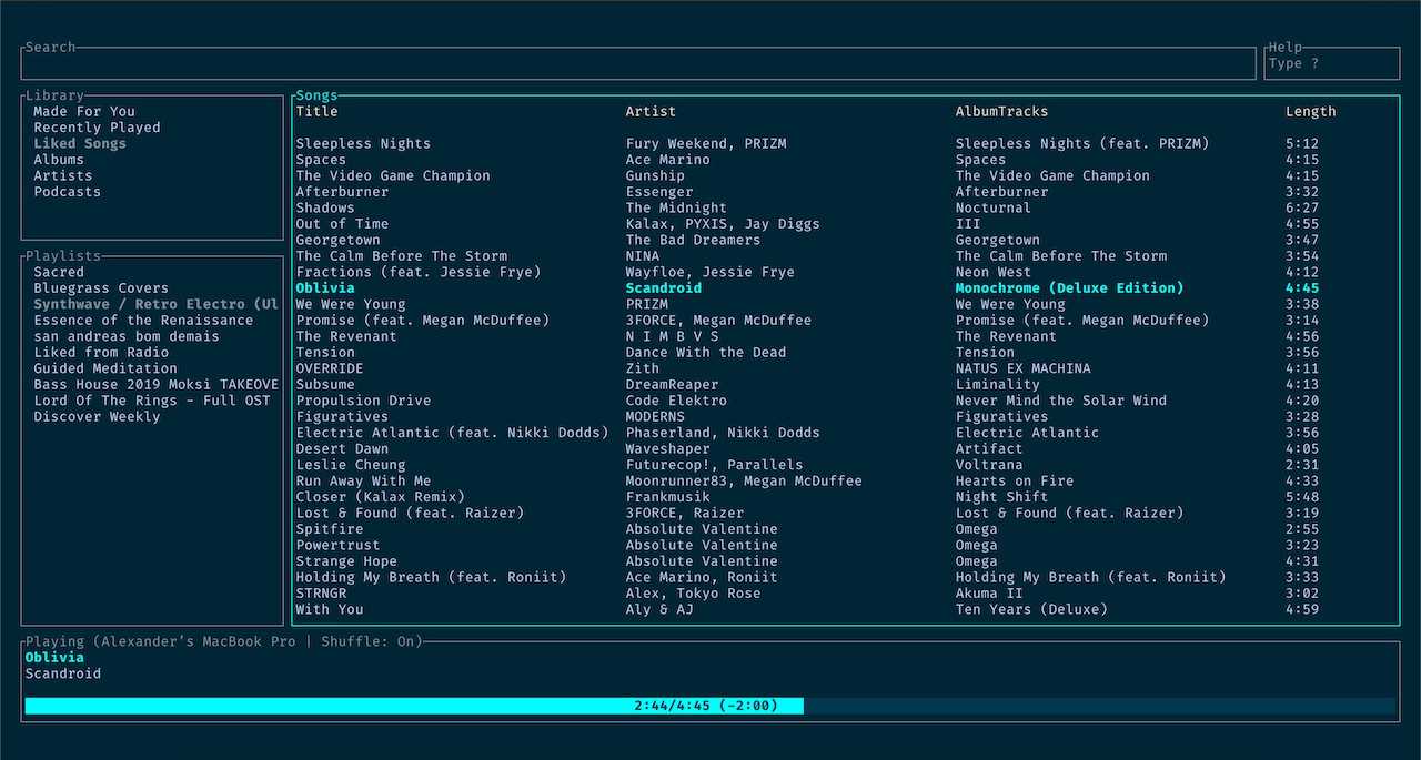
Cross-platform ncurses Spotify client written in Rust, inspired by ncmpc and the likes. - GitHub - hrkfdn/ncspot: Cross-platform ncurses Spotify client written in Rust, inspired by ncmpc and the li...

good thing is, you can run that via ssh
so you won't need to go up to the big, main display and click a bunch of buttons
it would also allow you to programmatically control the playback on that screen if you wanted to, pretty easily
that's a stand-alone that doesn't rely on spotifyd I think, but, it doesn't work with free spotify accounts
oh, I remember! spotify-tui is the one I was thinking of
GitHub
Spotify for the terminal written in Rust 🚀. Contribute to Rigellute/spotify-tui development by creating an account on GitHub.
novel mist
Thanks for the help. You guys saved the party 😄
I just needed to install libwidevinecdm0 from apt to make spotfy web working
west sierra
nice!!!
novel mist
I think you recognise wled 😄
 hoary turtle
What are some main uses for SSH on a pi?
 hardy plaza
hoary turtle
What are some main uses for SSH on a pi?
hardy plaza
hoary turtle
What are some main uses for SSH on a pi?
I do all my programming work directly on a Pi (in Python) and check my code into github directly from the Pi. All over an ssh connection. With shared keys I don't even use passwords to log in. Very convenient.
Remember that a Pi is just a normal Linux computer in most respects, so ssh is just part of the available tools.
hoary turtle
Ok, so what work flows do you do that with? I mainly create MERN / MERNG stack, also React + Firebase. I’ve been getting into c/c++ for embedded systems
hardy plaza
hoary turtle
Ok, so what work flows do you do that with? I mainly create MERN / MERNG stack, ...
With a Raspberry Pi I'm generally using them to build small autonomous robots.
The workflows are generally just Python builds directly on the robot itself.
hoary turtle
I’ve been wanting to create a hub to view data for video feeds for fish tanks, also temps. But I’m not sure what to use for the UI/GUI, if I should just create a local host, or a actual tablet for the monitor to view everything
hardy plaza
For my day job I'm a Java infrastructure developer, where we use Maven, Eclipse, etc. plus a full toolset behind the scenes (gitlab, etc.)
That depends on what programming language you want to use for the web services. Python and Java are relatively simple, I don't know what's available in C/C++.
 civic rune
hardy plaza
With a Raspberry Pi I'm generally using them to build small autonomous robots.
civic rune
hardy plaza
With a Raspberry Pi I'm generally using them to build small autonomous robots.
Do you ever find that the OS is a hindrance? I've found it getting in the way for the very basic, non robotic, things I'm doing
hoary turtle
hardy plaza
The workflows are generally just Python builds directly on the robot itself.
Should I use Kivy for my UI? I’m planning on using for my project C/C++, React
hardy plaza
civic rune
Do you ever find that the OS is a hindrance? I've found it getting in the way fo...
Then switch to an MCU where there is no OS and you're just running one program. For a few things on my robot that's what I do, and I've been generally happy with MicroPython for that, having ported some of my CPython over.
civic rune
Yeah that's my plan going forward once I clear the existing technical debt
hardy plaza
hoary turtle
Should I use Kivy for my UI? I’m planning on using for my project C/C++, React
I'd say whichever platform appeals to you, or you already know. I use Flask but any will do.
hardy plaza
civic rune
Yeah that's my plan going forward once I clear the existing technical debt
...like, clean out the basement?
civic rune
Lol like rip put hundreds of wires and dozens of ICs and replace them with a simpler, more streamlined MCU based build
hardy plaza
I've got a 4.5m³ skip showing up on Tuesday and I'm going to KonMare my basement, as well as get rid of the mud that's been washing in since March... 🙄
civic rune
KonMare?
hardy plaza
So different kind of cleanup.
hardy plaza
civic rune
KonMare?

Want to tidy using the KonMari Method™? Watch the step-by-step visual guide, KonMari Method™: Fundamentals of Tidying! ×
civic rune
Ohhhh
hardy plaza
yeah, that KonMari
civic rune
Nice. I need to get enough time off to do a deep clean and then I'm gonna do something about all the junk I have
hardy plaza
I think 2022 is going to be a clean-up-your-crap year.
civic rune
Yeah, I may have to hire someone though, 2022 is going to be a rough work year.
hardy plaza
civic rune
Yeah, I may have to hire someone though, 2022 is going to be a rough work year.
...for a lot of people.
 wanton seal
Hello, I'm very NOOB both to this server and to the raspberry-pi. I recently bought 3 Octocam's from Pimoroni (well from adafruit really) but am not sure what os I need to install on the sd card to get it working. I also bought one "16GB SD Card with Buster Lite" thinking that'll work (haven't tried but will be soon) ... just tried that ... Yay it booted to the login prompt (found pi and raspberry) but was lost. I looked up a video and was directed to https://learn.pimoroni.com/article/octocam but that url is broken 😦 error 500 for me now I'm not sure what to do. Anyone have any thoughts?
nvm just found https://learn.pimoroni.com/article/motioneye-os-on-your-octocam 🙂
Install and set up motionEye OS on your OctoCam – Pimoroni Learning Portal
hardy plaza
wanton seal
Hello, I'm very NOOB both to this server and to the raspberry-pi. I recently bou...
I've had a bunch of Octocams around my house for years now, with one now monitoring my basement floor to watch out for the next time it floods. Long story...
You can install a regular Pi OS and a camera, but it's a lot of work to gain the basic functionality you get out of the box with the MotionEye OS, which works just fine. I believe it's no longer being updated but that doesn't stop it from working. See:
https://github.com/ccrisan/motioneyeos

GitHub
A Video Surveillance OS For Single-board Computers - GitHub - ccrisan/motioneyeos: A Video Surveillance OS For Single-board Computers
wanton seal
OctoCam options
wanton seal
is there an amp limit for the power supplied to the Raspberry Pi Zero W? I'm using 5v upto 2.4amp ... Will that hurt it?
wanton seal
never mind it seems 2.4 amps don't hurt 🙂
of course, I still need help in the octocam options thread I started from Ichiro.Furusato's reply if anyone else can help
 umbral sable
wanton seal
is there an amp limit for the power supplied to the Raspberry Pi Zero W? I'm usi...
umbral sable
wanton seal
is there an amp limit for the power supplied to the Raspberry Pi Zero W? I'm usi...
Electronic devices will generally only draw as many amps as they need to operate, so it's not a danger to have a power supply rated for a higher maximum current. The voltage is what really matters.
wanton seal
umbral sable
Electronic devices will generally only draw as many amps as they need to operate...
thanks 🙂 wasn't aware of that.
 weary field
#help-with-circuitpython message
pi pico with nrf24l01 modules problem
 wicked hill
I'm running Debian Bullseye on a Pi 3B with a small LCD screen. I'm booting without the desktop, then running a small program. I would like to hide or disable the mouse pointer entirely. Unclutter and xdotool aren't working for me (I think because I'm not actually in an X session?) 2 days of Googling and I'm out of ideas.
 hard pine
change pointer icon to transparent PNG?
all icons
idk how it works on debian but
i'm familiar with this

and you would just change it to that for every mouse state
 faint sparrow
@wicked hill You may be without a window manager but if there's a mouse pointer it's something similar to X.org.
I just don't remember what.
I made an 'eBook TV' project out of a RPi3b.
I seem to remember I found a way to move the mouse-pointer to the edge of the screen.
It might have shown one or two pixels but I don't remember it as showing the entire arrow.
 hazy matrix
I got the Braincraft Hat (machine learning kit) with my raspberry pi 4, but i cant find any tutorials online on how to attach the included fan to the hat, and the hat to the board. is there any tutorial that i could use to help me attach all these?
 ripe berry
what is the voltage rating of the fan? Usually they are 5 V and you can either hook them to 5 V or 3.3 V if you’d like them to be quieter.
hazy matrix
not sure
im just trying to put the kit that i got together and cant find any insructions
ripe berry
Look at the fan itself and see what it says about the voltage rating
ripe berry
Is this what you have? https://learn.adafruit.com/adafruit-braincraft-hat-easy-machine-learning-for-raspberry-pi

Adafruit Learning System
Easily use Machine Learning on a Raspberry Pi 4 using the BrainCraft HAT
ripe berry
ada fruit usually has really good tutorials. It looks like that’s the one you want, maybe?
ripe berry
cool! try it out, and if you run into difficulty, come on back and someone will probably be able to answer your questions
hazy matrix
ok cool, thanks
hazy matrix
in the braincraft Hat kit, it came with a fan, and screws to screw it into place, but it also had nuts. am i supposed to use the nuts as spacers? cuz the photos of it on the adafruit site dont show where those nuts are placed.
civic rune
how can I tell what kind of pi I have if I only have easy access to the desktop via mouse/monitor/keyboard?
 humble marsh
civic rune
how can I tell what kind of pi I have if I only have easy access to the desktop ...
humble marsh
civic rune
how can I tell what kind of pi I have if I only have easy access to the desktop ...
 steady rose
dmesg|head
pi@raspberrypi:~ $ dmesg|head
[    0.000000] Booting Linux on physical CPU 0x0
[    0.000000] Linux version 5.10.63+ (dom@buildbot) (arm-linux-gnueabihf-gcc-8 (Ubuntu/Linaro 8.4.0-3ubuntu1) 8.4.0, GNU ld (GNU Binutils for Ubuntu) 2.34) #1459 Wed Oct 6 16:40:27 BST 2021
[    0.000000] CPU: ARMv6-compatible processor [410fb767] revision 7 (ARMv7), cr=00c5387d
[    0.000000] CPU: PIPT / VIPT nonaliasing data cache, VIPT nonaliasing instruction cache
[    0.000000] OF: fdt: Machine model: Raspberry Pi Zero W Rev 1.1
[    0.000000] random: fast init done
[    0.000000] Memory policy: Data cache writeback
[    0.000000] Reserved memory: created CMA memory pool at 0x17c00000, size 64 MiB
[    0.000000] OF: reserved mem: initialized node linux,cma, compatible id shared-dma-pool
[    0.000000] Zone ranges:
look for Machine model line
hazy matrix
im trying to put a hat onto my pi4, but its not going on all they way onto the gpio pins, how much is it supposed to go in, and what can i do to make it go all the way in?
civic rune
One sec let me get a pic of mine
west sierra
hazy matrix
im trying to put a hat onto my pi4, but its not going on all they way onto the g...
can you take a picture of the female headers on the hat, please?
civic rune
hazy matrix
im trying to put a hat onto my pi4, but its not going on all they way onto the g...
Here's a side view of a hat I designed (including wire bodges).
 west sierra
they might be the short ones, and you might have longer males on the pi
west sierra
k
civic rune
oh good!
civic rune
A cable like this will have no issue sending power to a pi right?
https://www.digikey.com/en/products/detail/qualtek/3025033-01/6235029
hardy plaza
civic rune
A cable like this will have no issue sending power to a pi right?
https://www.di...
The only question on these cables is that a lot of the ones you find as part of battery chargers only have the power connections but no data connections, so you can't mount a device using them, and you can't tell by looking at them. But if you're only looking for power then any USB-A to USB Micro B will work. That one qualifies.
civic rune
Yeah I just want power. There's no possibility of data transfer anyways. I guess it would be bad to have an unknown cable floating around but I'll cross that bridge when I come to it.
hardy plaza
One thing to note is that the actual power requirement of a Raspberry Pi is 5.1 volts, not 5 volts. They'll clearly run at 5v but they're at the lower end of their range. Considering the voltage drop across cables is a function of their length, it's probably best to find the shortest USB cable you can that will suit your purposes.
civic rune
Yup, my PSU will be trimmed up to 5.1V
hmm do they make a usb plug that you can pick power out of? I want to test that my trimming is working. I can use the USB-Barrel jack connector in conjunction with a spare barrel jack housing, but that cable is significantly longer than the USB cable I'm using, so voltage drop could be significant.
there it is.
Adafruit sells one.
hardy plaza
I just use a Y adapter cable, but you can also just use a probe and connect to the 5v pin on the Pi, which is connected to the USB supply on the other size of the fuse (MF-MSMF20/X, at PP7) or at PP2 on the board itself (on the underside) if you want the pin directly.
https://datasheets.raspberrypi.com/rpi3/raspberry-pi-3-b-plus-reduced-schematics.pdf
It really helps to learn how to read schematics... 😁
civic rune
I'm relatively comfortable reading other people's schematics. That one is on the high end of the complexity I can grok
hardy plaza
It's nicely divided by function, with the power up in the top left.
civic rune
yeah they did a good job
civic rune
Does anyone have experience powering the raspberry pi itself through a hat? I'm given to understand that it's totally possible but I'm a little wary of trying it.
hardy plaza
civic rune
Does anyone have experience powering the raspberry pi itself through a hat? I'm ...
I've done both (USB and powering the Pi from the 5v pin. As you and I were looking at the schematic earlier, what you're suggesting is to go around the fuse and safety circuitry on the Pi to provide 5 volts directly. If that's a safe 5 volts then you shouldn't have any trouble, but the risk is entirely clear.
As an example, the PyBorg ThunderBorg motor controller has an on-board 5 volt regulator with a 6 pin Dupont connector designed to power the Pi directly. I've used that arrangement for years with no issues.
civic rune
interesting OK. I think I'll stick with two PSUs for now and see if I can't figure out something that powers the pi thru the hat in future builds
technically I'm using 1 PSU but split into 2 channels but I'm not bypassing the fuse. I wonder if I could just add a fuse to the hat..
hardy plaza
To give you an idea of how that works, you might check out their Getting Started page: https://www.piborg.org/blog/build/thunderborg-build/thunderborg-getting-started

PiBorg
Installation Mounting on the Pi (optional) With most newer Raspberry Pis it is possible to mount the ThunderBorg directly to your Raspberry Pi: The six-pin socket on the ThunderBorg should fit snuggly on the first six GPIO pins of the Raspberry Pi. If you are using a Pi Zero you will need to solder pins to the first six GPIO pins before mounting...
civic rune
interesting. is that OSHW?
hardy plaza
OSHW?
Open Source hardware? I think there might be a schematic on their site somewhere, dunno.
 foggy onyx
<@&617066238840930324> see if you can
turbid rivet
Cna you provide more context of what you're trying to do?
foggy onyx
turbid rivet
Cna you provide more context of what you're trying to do?
After i boot this happens
And taskbar is disappeared
I can't use my computer
turbid rivet
foggy onyx
turbid rivet
https://support.vilros.com/hc/en-us/articles/4402069082772-I-ve-lost-my-Raspberr...
How can i open terminal ???
turbid rivet
SSH would be the easiest way, if you have its IP address.
foggy onyx
And it only says about disappeared taskbar
turbid rivet
Or CTRL ALT T
Oh, is it totally frozen?
Easiest way would be to reinstall the entire OS, but that assumes your files are all properly backed up...
foggy onyx
turbid rivet
Or CTRL ALT T
It didn't work
foggy onyx
turbid rivet
Oh, is it totally frozen?
No, i can open trash can
I was talking about error No session for pid 975
See my image
foggy onyx
turbid rivet
Easiest way would be to reinstall the entire OS, but that assumes your files are...
No, i didn't backuped
hoary turtle
I got the expansion gpio board for my pi4, how do I connect the fan again once it’s on?
foggy onyx
Please help me 🙏🙏🙏 Please help me 🙏🙏🙏 https://media.discordapp.net/attachments/538149593246859313/923231082659315792/20211222_203805.jpg , no session for pid xxxx error is coming and my taskbar is disappeared

 ruby night
Please do not tag the community helpers when you are looking for help. They or others will be happy to help if they can but tagging them is unnecessary and annoying.
foggy onyx
ruby night
Please do not tag the community helpers when you are looking for help. They or o...
Sorry
 gentle briar
foggy onyx
Please help me 🙏🙏🙏 Please help me 🙏🙏🙏 https://media.discordapp.net/attachm...
gentle briar
foggy onyx
Please help me 🙏🙏🙏 Please help me 🙏🙏🙏 https://media.discordapp.net/attachm...
Are you using VNC or Plex? It could be the taskbar is there but hidden (either it's set to auto hide, or the resolution does not match your monitor correctly).
foggy onyx
gentle briar
Are you using VNC or Plex? It could be the taskbar is there but hidden (either ...
No
It's a monitor
foggy onyx
gentle briar
Are you using VNC or Plex? It could be the taskbar is there but hidden (either ...
Taskbar blinks at bootup then disappears
gentle briar
That seems like the taskbar is set to auto hide.
foggy onyx
gentle briar
That seems like the taskbar is set to auto hide.
How can i fix error and taskbar ???
gentle briar
I suspect the error is from tightvnc, turn that off and the error should go away. Change the taskbar settings to turn off auto hide, and it should stay on your screen.
foggy onyx
gentle briar
I suspect the error is from tightvnc, turn that off and the error should go away...
But how can I do that
I don't have taskbar
gentle briar
Mouse down to the bottom of the screen and the taskbar should pop up
foggy onyx
gentle briar
Mouse down to the bottom of the screen and the taskbar should pop up
No, it won't
gentle briar
Then you may have to fix it via CLI.
foggy onyx
gentle briar
Then you may have to fix it via CLI.
How ??
Yaaaaa, opened terminal from trash can
From tools and open terminal in current directory
foggy onyx
gentle briar
I suspect the error is from tightvnc, turn that off and the error should go away...
Commands ??
foggy onyx
turbid rivet
https://support.vilros.com/hc/en-us/articles/4402069082772-I-ve-lost-my-Raspberr...
Commands in it won't work
For me
 chrome ridge
I have a Pi4 and the resolution is so high, I can't see anything from 3 feet away on my 4k 42" tv.
Any suggestions or recommendations to fix this would be great.
I plan on moving the pi4 into the SmartiPi case with the Official RPi 7" screen. Will I have issues with the screen and resolution on it too?
west sierra
chrome ridge
I have a Pi4 and the resolution is so high, I can't see anything from 3 feet awa...
Well, switching between 4k and whatever's on the 7" 1080p maybe? It's the same as on any computer.
west sierra
chrome ridge
I have a Pi4 and the resolution is so high, I can't see anything from 3 feet awa...
Are you in the GUI or on the terminal?
If you're in the terminal, blame the TV, it says: "give me all you've got" to the Pi, and the Pi is like, "sure thing boss" and feeds it a terminal in 4K. With super tiny text. Been many times I've had to do this in my living room. That's why I have a wireless keyboard so I can stand 2 feet from my TV and read the terminal.
Not sure, but it's got something to do with how the TVs negotiate resolutions via HDMI, and I think they're always opting for the highest possible by default, but there's nothing to tell the Pi that it should scale the text.
If you're in the GUI, you should be able to configure the defaults by clicking one of the 3 buttons, low/mid/high for display resolution and it should resize the graphical elements for you automatically.
You can also use the display scale, I think. I don't remember if the GUI has support for that as I do not use Raspberry Pi OS and the window manager very often. Most of my Pis with a window manager are running Manjaro ARM Sway because it's way, way faster when it comes to displaying things and switching between workspaces and windows. Because it's using Wayland.
chrome ridge
west sierra
Are you in the GUI or on the terminal?
I am using GUI RPi OS in hopes to set up a HamPi rig. The SmartiPi case is going to be used once I get it set up.
I have not seen the low/mid/high under config. I do have a few smaller monitors that I could use.
The weird thing is the Pi2b+ and Pi3 don't have this silliness with resolution.
west sierra
They don't support 4K. 🙂
chrome ridge
Ah. 🤦♂️
west sierra
chrome ridge
I am using GUI RPi OS in hopes to set up a HamPi rig. The SmartiPi case is going...
Give me a sec to look up the setting name.

that oughta help
there's also some stuff under screen configuration where you can manually control the scale
chrome ridge
Thanks.
There was a setting to "enable" that was supposed to help with the resolution on 4k tvs under configuration, but that just left it with the blinking underscore on the boot screen on restart
west sierra
what did it say to enable?
chrome ridge
I don't remember
west sierra
FYI, I referenced this particular forum post in formulating my answer to you:
https://forums.raspberrypi.com/viewtopic.php?t=257205
chrome ridge
It was the 3rd tab I think
Thank you. I am at the end of my cellular data allotment so loading webpages is very slow.
west sierra
chrome ridge
Thank you. I am at the end of my cellular data allotment so loading webpages is ...
no worries, I hope this helps
chrome ridge
It seems like it will. I just need to wait until the data resets on the third to reinstall and update the RPi OS
foggy onyx
Please help me 🙏🙏🙏🙏🙏 https://media.discordapp.net/attachments/538149593246859313/923231082659315792/20211222_203805.jpg , no session for pid xxxx error is coming and my taskbar is disappeared
foggy onyx
west sierra
If you're in the terminal, blame the TV, it says: "give me all you've got" to th...
Use ctr shift + or -
west sierra
If you're on a TTY?
That doesn't work unless you're in a terminal emulator that supports it.
west sierra
I called it terminal, maybe console is the correct term in English?
English is not my mother tongue ¯\_(ツ)_/¯
foggy onyx
foggy onyx
Please help me 🙏🙏🙏🙏🙏 https://media.discordapp.net/attachments/5381495932468...
Ya i remembered it happened after update to bullseye
ruby night
foggy onyx
Ya i remembered it happened after update to bullseye
Did this happen immediately after you upgraded to bullseye? That is, did it ever work under bullseye? Did you do the bullseye upgrade on your existing system or did you do a clean install of bullseye?
foggy onyx
ruby night
Did this happen immediately after you upgraded to bullseye? That is, did it ever...
Immediately after reboot after upgrade to bullseye from old one
ruby night
That is why it is not recommended to upgrade that way.... and always recommended to do a full backup before you do!
foggy onyx
ruby night
That is why it is not recommended to upgrade that way.... and always recommended...
What should I do now ??
A reupgrade
??
ruby night
The ideal way to install the latest OS is to backup all your project and data files and then do a clean install using Raspberry Pi Imager to write to a microSD card, but it is possible to upgrade an old Debian 10 “Buster” based Raspberry Pi OS to Bullseye.There is a caveat, however, as it may not be the smoothest of upgrades. So before you take the plunge make sure that you have a backup of any important files and projects. from https://www.tomshardware.com/how-to/upgrade-raspberry-pi-os-to-bullseye-from-buster
foggy onyx
ruby night
```The ideal way to install the latest OS is to backup all your project and data...
I didn't knew that
ruby night
I would do a clean install of bullseye. then re-install anything you had installed.
I tried the "upgrade" as described in that link once and it did not work for me. I have done clean installs for any systems I have since then.
and keep good backups from now on 😉
 vapid mantle
Hey people, we had some issues connecting the raspberry pi 0 to the adafruit rfm9x
Traceback (most recent call last):
  File "rfm9x_check.py", line 10, in <module>
    rfm9x = adafruit_rfm9x.RFM9x(spi, cs, rst, 433.0)
  File "/usr/local/lib/python3.7/dist-packages/adafruit_rfm9x.py", line 272, in __init__
    "Failed to find rfm9x with expected version -- check wiring"
RuntimeError: Failed to find rfm9x with expected version -- check wiring
Using the exact same code and wiring setup, the error is not reproduced on the raspberry pi 4
however, when using the raspberry pi 0 w, there seems to be an error
we have triple checked our wiring, and we have used exactly the same code between the rpi4 and rpi0, so we are pretty sure that the code is not the issue.
if anyone could help us that would be greatly appreciated
ruby night
vapid mantle
we have triple checked our wiring, and we have used exactly the same code betwee...
I don't have any suggestions to offer other than keep checking the wiring. I have used RFM9x boards with both the Pi zero w and Pi 4 with no problems. I wish I had more to offer.
Are you using the breakout board or the "bonnet"
vapid mantle
we are using a breakout board, with the pins soldered on to this board
and using female-to-female cables to connect from the pins on the rfm9x directly to the rpi 0
ruby night
and the Pi zero header is soldered as well?
vapid mantle
yes
ruby night
same cables you use for the 4B -- try different cables -- they do break --- getting desperate 😉
vapid mantle
just to add we using CE1 (GPIO 7) for CS. and D6 (GPIO 6) for RST. Are these the recommended ports?
ruby night
They should be fine.
vapid mantle
ruby night
same cables you use for the 4B -- try different cables -- they do break --- gett...
we have tested it using the same cables that worked with the rpi4
also do we need to connect the G0 pin on rfm9x, and if so, where on the rpi0 do we connect it?
ruby night
vapid mantle
just to add we using CE1 (GPIO 7) for CS. and D6 (GPIO 6) for RST. Are these the...
these are also wht you use on the 4B?
vapid mantle
ruby night
these are also wht you use on the 4B?
yes
ruby night
vapid mantle
also do we need to connect the G0 pin on rfm9x, and if so, where on the rpi0 do ...
You don't need G0 for the CircuitPython library
ruby night
possibly -- and a picture of the soldering of the Pi header and breakout pins. Did you try the same breakout on the pi4 and the pi0?
vapid mantle
ruby night
possibly -- and a picture of the soldering of the Pi header and breakout pins. ...
the pi 0 came pre soldered, so i doubt that would be the same issue
and we did try the same breakout on the pi4 and the pi0
the pictures:
 ruby night
ah -- probably ok take a close look to make sure none of teh pins are bridged. Or if you have a multimeter test the continuity.
vapid mantle
 vapid mantle
ruby night
ah -- probably ok take a close look to make sure none of teh pins are bridged. O...
vapid mantle
ruby night
ah -- probably ok take a close look to make sure none of teh pins are bridged. O...
sorry, how would you test the continuity?
ruby night
check for zero resistance between the pi header and breakout board header.
vapid mantle
ok, is this for every pin that is currently in use?
ruby night
it is had to tell from your picture -- double check that you are on the correct row of pins for the Pi zero
second picture looks OK
vapid mantle
i just don't understand why the same setup works on the rpi4, but not on the rpi0.
ruby night
I'm sorry -- I have to go offline -- I wish I could help ....
hoary turtle
When i have 2 Pi4, and i “connect” them, does that mean i have 16gb of ram? What’s a good reference of how to handle tasks? I wan to use VSCode, but its slow
 spiral mason
Is using VSCode remotely an option ?
humble marsh
hoary turtle
When i have 2 Pi4, and i “connect” them, does that mean i have 16gb of ram? What...
I'm not sure what you mean by "connect", but they are separate computers, and their capacity is not combined. They can talk to each other, but you can't run a single program across both. You could remotely start programs on one from the other, but that's some work.
Consider two Windows computers next to each other on your desk, as a comparison
humble marsh
spiral mason
Is using VSCode remotely an option ?
You could use it through VNC or other remote desktop option, or possibly set up remote X Windows.
hoary turtle
humble marsh
I'm not sure what you mean by "connect", but they are separate computers, and th...
Ok, I’ve seen “pi super computers”, so theres no way to run bigger programs? What’s a benefit from a “cluster”?
humble marsh
There is special software to spread running tasks in parallel across multiple computers. Yes, you can do that, but you need to figure out how to segment up your computations into parallelizable chunks. What are you try to compute?
by a single program, I meant, say, a simple Python program. But there are libraries to manage tasks across multiple machines.
hoary turtle
humble marsh
There is special software to spread running tasks in parallel across multiple co...
Thank you
 frosty kernel
Just a little question for the adafruit Feather RP2040, wich pins are compatible with PIO ?
faint sparrow
@frosty kernel It might be on the pinout diagram (I don't know).
frosty kernel
Maybe I missed it but I don't think so
ruby night
@faint sparrow --"great minds ..." #help-with-circuitpython message
faint sparrow
@ruby night ;)
Yeah I'm 85 percent convinced the PIO works with every single pin in that series (about 29 of them I think).
ruby night
30 -- counting 0
from Chapter 3.2.5 Each of these operations is on one of four contiguous ranges of GPIOs, with the base and count of each range configured via each state machine’s PINCTRL register. There is a range for each of OUT, SET, IN and side-set operations. Each range can cover any of the GPIOs accessible to a given PIO block (on RP2040 this is the 30 user GPIOs), and the ranges can overlap.
faint sparrow
p.26
PIO0_BASE 0x50200000 AHB_Lite peripheral
(PIO1_BASE 0x50300000)
The other one [APB] is0x40000000 based
ruby night
I was just pointing at this part : on RP2040 this is the 30 user GPIOs
faint sparrow
I think there's one (near GPIO27) that has some funky business associated with it.
I don't remember the details though.
Maybe it's used as a sense pin associated with BOOTSEL .. I just don't remember, only that it was a very specific pin.
ruby night
I suppose there may be some board specific limitations....
faint sparrow
I think it may be the Pico (USD $4 RP2040 board) that uses 'housekeeping' duties for at least one pin.
frosty kernel
Nis and Jerryn thanks for your help too :)
faint sparrow
;)
I looked through the Pico board datasheet pretty thoroughly.
Was not especially alerted to any single pin as .. a big problem.
frosty kernel
So for short nearly any pins support PIO ?
faint sparrow
Yeah I would say so.
Why is it important to know at the moment?
You could just find out as you go along.
There's a set of devices inside the chip .. it is a bit like a railroad switch-yard in there.
It routes stuff.
The documentation is very suggestive of that the PIO can be routed to all GPIO pins.
If you dig you can find the programmatic interface to make that happen.
 zinc jackal

Kubernetes
On-disk files in a container are ephemeral, which presents some problems for non-trivial applications when running in containers. One problem is the loss of files when a container crashes. The kubelet restarts the container but with a clean state. A second problem occurs when sharing files between containers running together in a Pod. The Kubern...
west sierra
I need (want) to use PoE to power a device that'll hang out on the wall of my house. Question is, would it be possible for me to stack my LoRaWAN concentrator on top of the RPi PoE+ HAT?
https://www.adafruit.com/product/5058
https://store.rakwireless.com/products/rak2245-pi-hat?variant=39945102000326
If not, then I assume I need to get the PoE USB C splitter.
I have ordered a router that supports 802.3at/af, so that part is taken care of.
I was worried it would cost me a lot, but I found a decent one for $49.99.
frosty kernel
faint sparrow
You could just find out as you go along.
I wanted to make a schematic for my game console idea but that's complexe, I've been doing hours of research
turbid rivet
frosty kernel
I wanted to make a schematic for my game console idea but that's complexe, I've ...
It might make more sense to create a proof of concept/prototype with a breadboard if you’re not experienced with these designs. Creating a schematic tends to be easier when you can make iterative revisions.
 patent patio
Anyone out there that can help me with an error installing Blinka on a pi zero w?
hardy plaza
patent patio
Anyone out there that can help me with an error installing Blinka on a pi zero w...
Generally it's best to just describe your problem in detail (the better described, the more likely the response) rather than asking someone to commit to helping you.
patent patio
I'll give it a try
I'm using the adafruit guide to install blinka on a pi zero w. Everything works fine till i use the command "sudo python3 raspi-blinka.py". Then I get a Blinka error "Broken Packages". and Blinka Some packages could not be installed. This may mean that you have
Blinka requested an impossible situation or if you are using the unstable
Blinka distribution that some required packages have not yet been created
Blinka or been moved out of Incoming.
Blinka The following information may help to resolve the situation:
Blinka
Blinka The following packages have unmet dependencies:
Blinka vlc-bin : Depends: libvlc-bin (= 3.0.16-1+rpi1+rpt1) but 3.0.16-1+rpi1+rpt2 is to be installed
Blinka vlc-plugin-skins2 : Depends: vlc-plugin-qt (= 3.0.16-1+rpi1+rpt2) but 3.0.16-1+rpi1+rpt1 is to be installed
Blinka Exiting due to error: Apt failed to install software!
 olive haven
@patent patio How did you install Raspbian? Was it a fresh install?
hardy plaza
patent patio
I'll give it a try
Sometimes you receive an error and left with a condition where you cannot add a new package nor update or delete the existing packages until you fix the problem. In this article, we will learn how to fix the missing dependencies and broken packages using the apt-get command.
patent patio
Was a fresh install, but I found a fix using sudo apt full-upgrade and then rerunning the script
Thanks
 hot oar
Hello, I was working on Pi and it froze to the point that anything that I click doesn’t respond. I tried a few suggestions from forums like clicking cntl alt f1 to get terminal to appear and the reboot, etc, but even after doing that, it allows me to get till the home page and all the IO peripherals such as my keyboard and mouse work but there is no reaction to clicks on any programs or buttons or any sort. Does anyone know any remedies? Really on an urgent timeline. Please help! Thanks!
hot oar
hot oar
Hello, I was working on Pi and it froze to the point that anything that I click ...
This is a Rasp Pi 3 B+ btw
Correction: I can open Trash (on the desktop) but nothing on the task bar is accessible.
 urban python
i have an rpi4 with the rpi 7" official touch screen, im trying to use FreqShow https://learn.adafruit.com/freq-show-raspberry-pi-rtl-sdr-scanner/ I had to tweak some of the config to get it to use the /dev/fb1 and its showing up (and looks like its connected to the sdr device) but im having some trouble figuring out what the touch screen device is, the example says /dev/input/touchscreen (which I dont have at the console, if i boot into X the touch screen works but I still dont have /dev/input/touchscreen) i have some /dev/input/mouse[0,1,2] but none of them seem to work as the touch screen with the freqshow.py, any ideas what other device it might be?

Adafruit Learning System
See what's in the radio waves around you using software-defined radio and a Raspberry Pi!
 tidal cove
Hi, guys, I'm working on an STS- pi robot. I've attached an anker 5000 external battery, but Bluetooth service does not start on the battery, if i remove the battery and connect it to the socket everything works. any ideas what might be wrong?
hardy plaza
tidal cove
Hi, guys, I'm working on an STS- pi robot. I've attached an anker 5000 external ...
I think you've already identified the problem: your power supply. The Raspberry Pi actually requires 5.1 volts, and if you use a 5 volt battery you're already at the lower end of the Pi's voltage requirements. If you push the ability of the battery to deliver it will "brown out" and drop its voltage even further. You can help this a bit by using a very short and high quality USB cable, but that will only go so far. You should investigate some better battery-based power supply for your robot, perhaps an adjustable buck-boost supply, or one designed for the Pi, one that can handle both more than and less than 5.1 volts. This is for the Pi Zero but there are others for other Pi models: https://www.adafruit.com/product/4114

When your Raspberry Pi project requires multiple power supplies, why not check out the new Zero2Go Omini? This multi-input power supply buck-boost converter fits on top of a Raspberry ...
But you'll need one with a current capacity totalling that of your Pi plus any peripherals. Pololu has some as well.
The other thing you can do is look at your Pi's system logs, found in /var/log/
tidal cove
so if i have an explorer pro hat, and the 2 connected motors, + an ulltrasonic sensor, + a nightvision camera, i'm guessing that's way too much for the single battery
how would i go about if i wanted to connect another battery, one dedicated for the pi and another for the motors?
hardy plaza
You need to power your motors from a separate supply, or at least a separate and spike-protected voltage regulator off the same battery. No question. Many motor controllers let you do this.
You're way over current-wise what you can do with that battery on its own, mostly because of the motors (motors and heaters take a lot more power than other things, and the IR lamps on the night vision camera are pretty high current if I remember correctly).
 wraith grove
urban python
i have an rpi4 with the rpi 7" official touch screen, im trying to use FreqShow ...
wraith grove
urban python
i have an rpi4 with the rpi 7" official touch screen, im trying to use FreqShow ...
"Private video"...?
ripe berry
Hm. Looks like all the directions are there with pictures, so the video would be unnecessary anyway.
 static perch
Hello, not sure if this is the correct forum to ask, but here goes. Looking to build my own, diy multispectral camera to be used on a farm to use on crops. Ive found a site where someone has been building this now for a couple of years now. I'm not sure if these components are ..common or semi-common or not. Here is a paragraph from his article: Visible-bands Raspberry Pi camera is easy, cheap to assemble, however, there is only so much we can do with RGB images. So I decided to make a low-cost high-quality multimodal camera system with Raspberry Pi at its core that combines multispectral (NOT w/ a cheap blue filter!!) and thermal imaging (thermal-VIS-NIR) plus light sensor and a range finder. You can connect the ClimaVUE50 all-in-one meteorological sensor (Campbell Scientific) directly to the imager's SDI-12 port. The system has a GUI with embedded computer vision and crop models.
umbral sable
Full high-res multispectral cameras are still fairly specialized components, intended for industrial and scientific use. If you can get away with low resolution, even just a single pixel spectral color sensor to scan a particular plant you point it at, then those are more hobbyist-approachable.
static perch
That is what I was afraid of. 2 strikes on me now. Thanks
umbral sable
static perch
That is what I was afraid of. 2 strikes on me now. Thanks
Heh heh, sorry. If there were an easy $20 invention that would revolutionize farming, chances are someone would already be selling it and making a fortune in the process. 😉
 vocal lava
I bought a Matrix Bonnet for a Pi (https://www.adafruit.com/product/3211) which should arrive from Digikey in the next day or two. The guide mentions a "quality" option that comes at a cost and requires you solder a jumper wire and you lose sound. How much better image quality are we talking about - does anyone know?

You can now create a dazzling display with your Raspberry Pi with the Adafruit RGB Matrix Bonnet. These boards plug into your Pi and makes it super easy to control RGB matrices such as those ...
static perch
I know, there are things out there, but for a small operation we have, its tough to justify spending that kind of money. Was hoping maybe I could piece something together. But that is how it goes.
umbral sable
static perch
I know, there are things out there, but for a small operation we have, its tough...
Don't let me discourage you too much. It is totally possible to homebrew some useful stuff, but you just have to keep your expectations modest when you are starting off. Like, if I wanted to get into farming, obviously my first step would be something like a vegetable garden rather than immediately trying to convert my SUV into a tractor. 😉
civic rune
how proper is it to power a pi through a hat and the 5V pins?
I could cut my BOM down a bit if it were possible to do so.
from my reading, I'd be adding some risk to the system.
like by bypassing the fuses that protect against short circuits
static perch
You are not..I'm use to failure. I always dive in head first when I see something. Heck, this time last year I knew nothing about 3d printing at all, in Feb of this year got first printer to make own ear tags using tpu. Have turned out real nice. But after that..ive kinda gone crazy. Long story short, my wife is in a wheelchair and I thought of a project to help her, I ended up driving like 5 hours away to buy a big custom 3d printer someone built from scratch. I hope I'm in the final stages of it before I put it together.
static perch
Hypothetically..do you all have the needed sensors and lenses that I would need to build it?
 arctic knoll
Is there any documentation available for the test pad touch points on the underside of the pi zero w 2?
 bleak brook
hello, I am trying to use a PDM microphone breakout from adafruit with my raspberry pi 4. I am trying to use the example code from the learn guide however I am having trouble installing the libraries. I just installed blinka, however when I run the first example from the guide (https://learn.adafruit.com/adafruit-pdm-microphone-breakout/circuitpython), I get the error "ModuleNotFoundError: No module named 'adafruitbusio'
any help would be appreciated
humble marsh
bleak brook
hello, I am trying to use a PDM microphone breakout from adafruit with my raspbe...
Blinka does not have support for audiobusio (yet).
It is supported on various native CircuitPython boards with I2S support.
civic rune
humble marsh
It is supported on various native CircuitPython boards with I2S support.
Does it currently, or will baremetal CP on the pi be able to make use of the audio jack on the pi?
humble marsh
civic rune
Does it currently, or will baremetal CP on the pi be able to make use of the aud...
not currently, "will", I imagine.
civic rune
Cool thanks
bleak brook
humble marsh
Blinka does not have support for `audiobusio` (yet).
bummer... well then is there a solution to get the pdm mic working in the meantime? i’m just trying to print out the audio levels. thanks
vocal lava
I have 2 32x64 panels and my Matrix Bonnet arrived today. I soldered the jumper to 8 per the instructions: https://learn.adafruit.com/assets/63007 - But I cannot get it to drive 64x64. It says it is, but its just mirroring 32x64.
I ran this: sudo ./demo -D0 --led-rows=64 --led-chain=2 and you can kind of tell it's mirrored

There, that picture works of my solder job

If anyone has any hints or suggestions, let me know. Thanks!
The other weird thing I'm seeing is that when I have to specify 32 columns and it thinks it's 64: ```pi@matrixpi:~/rpi-rgb-led-matrix/examples-api-use $ sudo ./demo -D0 --led-cols=32 --led-rows=64 --led-chain=2
Suggestion: to slightly improve display update, add
isolcpus=3
at the end of /boot/cmdline.txt and reboot (see README.md)
Size: 64x64. Hardware gpio mapping: adafruit-hat
There is a long discussion here about PDM and I2S on RPi. I have not looked through it in detail but was pointed to this from elsewhere: https://forums.raspberrypi.com/viewtopic.php?t=8496&sid=231cfae198191ebb12ba31bb0eed016c
 void mantle
I have a pi zero w , can you power the pi from the 3v gpio or only the 5v gpio?
hardy plaza
The 3.3 volt is not an input, it's the output of the Pi's on-board regulator. You can use the 5v GPIO pin, but that's not really recommended unless your power supply is a tightly regulated 5.1v supply. It's must safer to power the Pi via the USB socket labeled "PWR IN". That's the way it was designed to be used. https://pinout.xyz/pinout/3v3_power#
Raspberry Pi 3v3 Power Pins
void mantle
@hardy plaza thanks for the info!
turbid rivet
civic rune
how proper is it to power a pi through a hat and the 5V pins?
Some HATs are designed to do that, but it would be best to check the HAT itself and confirm its output to make sure it’s sufficient for your model of raspberry pi.
civic rune
turbid rivet
Some HATs are designed to do that, but it would be best to check the HAT itself ...
Ah sorry I'm making the hat
So it's not a true hat, it's a homebrew thing
hardy plaza
civic rune
Ah sorry I'm making the hat
Then you could either design a regulator or mount an existing product on your HAT, power that regulator, and route its output onto pin 5 of the Pi.
I think we've already checked out the Pi schematic so you're on your way.
civic rune
I'm planning on using a regulated trimmed up 5.1 V supply in and just duplicating the protection circuitry of the pi on the hat
hardy plaza
civic rune
I'm planning on using a regulated trimmed up 5.1 V supply in and just duplicatin...
Sounds like a plan 👍
civic rune
Thx
 clever venture
I'm trying to use NRF24l01 module with raspberry pi anyone has a source or a good link that I can get help?
ruby night
clever venture
I'm trying to use NRF24l01 module with raspberry pi anyone has a source or a goo...
you will also need "blinka" on the Pi https://learn.adafruit.com/circuitpython-on-raspberrypi-linux
clever venture
@ruby night thank you
 inland escarp
So, is it possible to power a Pico though any of the GP ports? or would I have to tap into the micro usb port to supply power? This is what I have but I want to 'slim' it down and have it powered via the unit its transmitting through. Aka. Pico is on when unit is on. Pico is off when unit is off.
Thanks in advance

 rotund pivot
@inland escarp see page 15: https://datasheets.raspberrypi.com/rp2040/hardware-design-with-rp2040.pdf
 fierce spire
Hi guys, I have a problem concerning the adafruit bno055 IMU:
Ich run a python script on my rasperry pi zero w, that simply takes the eulerangle-, linear acceleration- and gyroscope-values every 0.2 seconds, measured by the bno055 sensor and writes those down into a textfile by first converting the tuple into a string, then replacing the spaces with .replace(" ","") and then writes the resulting string into the textfile.
The problem is, that it often writes down values, that don't make sense like -+2000° orientation or +-300 m/s² of acceleration or sometimes even (None,None,None)...
Is it possible, that the tactrate is too high for the sensor or my rasperry pi zero (the old one by the way) or do I make something wrong (maybe with the .replace methode) or may the sensor even be broken?
Thank you for your help!
humble marsh
fierce spire
Hi guys, I have a problem concerning the adafruit bno055 IMU:
Ich run a python s...
replace() should be fine, but if you slow the rate down, do the readings get more reasonable?
The BNO055 has some problems with its I2C implementation, and you may be reading bad data. You could print out the actual bytes that you're reading and see whether some are zero, are repeated, etc.
fierce spire
Ok I'll try this. Thank you very much!
tidal cove
Hi, I am trying to set up the Eyes bonnet on a raspberry pi 3, i've installed the required software, but my screen are black, and when i try to run the eyes.py i get a libEGL warning: DRI2 failed to authenticate and nothing comes up on the 2 TFT 240x240 screens
 thin elm
Hi ,
I have a Pi4B running ubuntu and and want to use a Waveshare 1.5inch OLED Display Module using the I2C Interface (ssd1327)
I have it set up to use i2c but i seem to be having an issue when trying the sample code to test the display.
I am a bit of a newby to this so forgive me if i have missed the obvious but if i run the examples I get
as far as the following code (the first part of the example code)
#########################################
import board
import displayio
import terminalio
from adafruit_display_text import label
import adafruit_ssd1327
displayio.release_displays()
Use for I2C
i2c = board.I2C()
display_bus = displayio.I2CDisplay(i2c, device_address=0x3d)
WIDTH = 128
HEIGHT = 128
BORDER = 8
FONTSCALE = 1
display = adafruit_ssd1327.SSD1327(display_bus, width=WIDTH, height=HEIGHT)
###############################################################################
But get the following error and i am not sure why or what to try next,
ubuntu@ubuntu:~/OLED_Stats$ sudo python3 128test01.py
Traceback (most recent call last):
File "/home/ubuntu/OLED_Stats/128test01.py", line 13, in <module>
display = adafruit_ssd1327.SSD1327(display_bus, width=128, height=128)
File "/usr/local/lib/python3.9/dist-packages/adafruit_ssd1327.py", line 65, in init
super().init(
File "/usr/local/lib/python3.9/dist-packages/displayio/_display.py", line 135, in init
self._initialize(init_sequence)
File "/usr/local/lib/python3.9/dist-packages/displayio/_display.py", line 171, in _initialize
self._send(command, init_sequence[i + 2 : i + 2 + data_size])
File "/usr/local/lib/python3.9/dist-packages/displayio/_display.py", line 186, in _send
DISPLAY_COMMAND, CHIP_SELECT_TOGGLE_EVERY_BYTE, bytes([command] + data)
TypeError: can only concatenate list (not "bytearray") to list
umbral sable
thin elm
Hi ,
I have a Pi4B running ubuntu and and want to use a Waveshare 1.5inch OLED ...
That unfortunately looks like a bug in the library. The particular line throwing the error was changed just two weeks ago on GitHub, so that may have introduced a problem which wasn't caught in testing.
There's an open issue on it with a pending fix: https://github.com/adafruit/Adafruit_Blinka_Displayio/issues/77
GitHub
A Discord user mentioned in the #help-with-circuitpython room having an error raised by this line: Adafruit_Blinka_Displayio/displayio/_display.py Line 186 in 3354aab DISPLAY_COMMAND, CHIP_SELECT_T...
thin elm
ahh cool, thanks, i guess i will have to wait for a fix... (wish i had come here and asked first as i spent ages today trying work out what i had done wrong 😆 )
umbral sable
The fix is just a tiny edit to _display.py, if you want to make it in your local library: https://github.com/adafruit/Adafruit_Blinka_Displayio/pull/78/commits/d346d8c481f6c65ce64504b8c475194e1b4083dc
 elfin tree
If I am understanding correctly, I can only have 2 of these, https://www.adafruit.com/product/3660, on my raspberry pi model B (i2c address is 77 out of box, but shorting SDO to GND wil change address to 76) . Is this correct? Are there add on boards to allow me to use more than 2?
umbral sable
elfin tree
If I am understanding correctly, I can only have 2 of these, https://www.adafrui...
To use more, you're looking for an I2C multiplexer, such as https://www.adafruit.com/product/2717

You just found the perfect I2C sensor, and you want to wire up two or three or more of them to your Arduino when you realize "Uh oh, this chip has a fixed I2C address, and from what I ...
elfin tree
umbral sable
To use more, you're looking for an I2C multiplexer, such as https://www.adafruit...
that's the ticket! thanks!
 sonic cedar
I'm having a sort of odd issue where I can run a program in Thonny without issue, but when I run that same program in terminal, I get the following error: "ALSA lib pcm.c.8545:(snd_pcm_recover) underrun occurred". The audio becomes very choppy
I also tried running in terminal Sudo python /path/to/file and Sudo python3 /path/to/file. Just find it weird that it works perfectly fine in Thonny but not terminal. Any help getting it to work in terminal would be appreciated
thin elm
umbral sable
That unfortunately looks like a bug in the library. The particular line throwing...
Thanks, changed that and its working now! Brilliant..!
thin elm
I may have spoke to soon. The example code runs but the screen shows an odd pattern instead of the hello world example.text. (that black line across the screen is only puckwd up.by my camera and not visible to the naked eye) any ideas ?
 humble marsh
thin elm
I may have spoke to soon. The example code runs but the screen shows an odd patt...
humble marsh
thin elm
I may have spoke to soon. The example code runs but the screen shows an odd patt...
@thin elm Could you post your findings and photo as a comment in the pull request? https://github.com/adafruit/Adafruit_Blinka_Displayio/issues/77
thin elm
humble marsh
<@910964719857336400> Could you post your findings and photo as a comment in the...
have just done it now
clever venture
I'm working on NRF24l01 module with raspberry pi and I followed this link http://thezanshow.com/electronics-tutorials/raspberry-pi/tutorial-32-33 Now I'm trying to run the code it give me an error

I would appreciate any help
hardy plaza
clever venture
Have you installed the RPi.GPIO library yet?
 vapid acorn
I need help with a Thermal Printer. Isnt precisely the one Adafruit sells but looks exactly the same the name is HS-QR71 https://es.aliexpress.com/item/4001277878501.html

aliexpress.com
¡Compra fácil, vive mejor! Aliexpress.com
I followed the guide on Adafruit https://learn.adafruit.com/networked-thermal-printer-using-cups-and-raspberry-pi/connect-and-configure-printer

Adafruit Learning System
Thermal printer results like you’ve never seen…
I have a RPi4, updated, with serial console off, and the latest raspbian version with Desktop
when I try to "lp" any image, specially QR codes, it prints them short, not a full scale (I do the fit-to-page)
But when I "echo | /dev/serial" works fine

I thought it was some difference in config on the Printer Settings on the Pi or the ppd file. But when i compared the specs they are the same.
Specially the dot/mm
So, any suggestion on how to debug?
west sierra
I have a question about the POE+ HAT for the Raspberry Pi 4. Is it supposed to have a sort of... whiny fan? I am connected to a proper router (TL-SG1005P) witth 4x PoE+ (802.3at/af). Currently it's the only thing plugged in. Just curtious if anyone's got any thoughts on that? I was going to run Home Assistant on this guy, but from what I can tell, he's getting a bit warm.
I couldn't find a heat sink that would fit underneath that PoE+ HAT.
This thing is cooking.
civic rune
Obviously the solution is to design and print a custom water block + loop
Laser sinter printing too
west sierra
Yeah, maybe I can afford that setup if I sold the truck, and my wife's new SUV?
civic rune
Better sell the dog too
olive haven
To my taste, the 3B+ hit a sweet spot of performance vs heat
hardy plaza
olive haven
To my taste, the 3B+ hit a sweet spot of performance vs heat
Yes, that's still my go-to board for pretty much everything. Hard to improve it really.
civic rune
I had my work but 5 3A+s when I heard the 4s were going up in price. Now at least adafruit is sold out of the 3A+. Haven't checked around but I wouldn't be surprised if others were sold out too.
hardy plaza
I can't really buy from Adafruit directly anymore as the USPS no longer ships to New Zealand (!) and the courier costs are outrageous now, hard to justify ordering anything if there's immediately a minimal US$45 (NZ$66) additional cost on every order. By comparison, Canada Post (e.g., CA$13/NZ$15) or Royal Post (e.g., £9/NZ$17) are still pretty reasonable, and sadly, shipping from China is often free (I believe that's because it's government subsidised).
west sierra
yeah, can't really find any 3s floating around anywhere that isn't in some price gouged "bundle"
west sierra
hardy plaza
I can't really buy from Adafruit directly anymore as the USPS no longer ships to...
hey yo, let me know if I can help... I don't think I'd break any laws if you ordered a bunch of stuff to my house (please, no glitter d**ks) and I then shipped all that to you in one big box of joy.
hardy plaza
west sierra
hey yo, let me know if I can help... I don't think I'd break any laws if you ord...
Hi, thanks. Unfortunately the cost of getting it to you plus the cost of you shipping it here isn't much less.
west sierra
Yeah, might not be come to think of it. Thought I'd offer just in case.
hardy plaza
Appreciated. You're in the UK?
west sierra
US, North Carolina.
hardy plaza
Yeah, then you'd have the same trouble as Adafruit, no USPS to NZ...
Last year I ordered four packages of robot parts from goBILDA, and they were each shipping in mostly-empty FedEx boxes that cost NZ$125 each. 😖
west sierra
yeah, that's true, but I was more thinking if you had a bunch of smaller orders for things, like components or whatever, that you wanted to bundle, take me up on it and I'll help
hardy plaza
Much appreciated.
west sierra
like, if you order a bunch of small stuff from like Digikey or whatever, and then some from Adafruit, and some from Sparkfun, and you know...
I have a rant about shipping costs, moving into #general-chat
hardy plaza
For some strange reason, SparkFun has an 'economy' option that takes up to 6 weeks but only costs US$3.49. I have no idea how they do that. Their corresponding FedEx (for the same order of one item) is $50.73 and UPS $38.72. I wish Adafruit did something like that (whatever that is).
civic rune
I guess I'm probably not moving to new zealand. I love my adafruit orders
Your climate and people are very tempting though
west sierra
I try to get free shipping, but it's like, I already placed several $200 orders. Did I actually even save anything? 😄 And, now I have all these wild cool STEMMA breakout boards that I don't know what to do with... yet.
and I keep forgetting to check the live stream for coupon codes...
hardy plaza
civic rune
I guess I'm probably not moving to new zealand. I love my adafruit orders
Everybody in the world seems to want to move here, but it's hardly the paradise it might seem from afar (nowhere is). As an example: would you take a 30% cut in pay, a 30% increase in food costs, a 200% increase in costs for housing, electronics and other goods, and a significant decrease in availability of products you take for granted?
civic rune
Interesting. No, probably not. But a massive decrease in medical costs is tempting as well
Where I live, if you want to see a specialist you're breaking 3 figures and waiting 6 months
hardy plaza
If you're in the US you could move almost anywhere in the world to get more affordable medical.
civic rune
I am
west sierra
You're better off moving somewhere like Sweden or Finland, though. Housing costs are down. Only kicker is the gas prices.
New Zealand is an island, where space is at a premium (gotta fit all those doomsday bunkers somewhere, right?)
so housing costs are obviously going to be harsh
Anyway, that should all probably go to #general-chat.
frosty kernel
Is it possible to add RAM to the rpi pico/a custom board with RP2040 ?
hardy plaza
frosty kernel
Is it possible to add RAM to the rpi pico/a custom board with RP2040 ?
Not RAM so far as I know. The existing flash is integrated into the board.
If you're trying to get better performance or more space than is available on an SD card you might try plugging a portable SSD into the USB port, or getting one of those M.2 extension HATs and using an M.2 style SSD.
civic rune
I'm looking at using this board https://learn.adafruit.com/adafruit-aw9523-gpio-expander-and-led-driver?view=all#python-circuitpython with the pi. But since the board has 10k pullups, the total bus resistance is brought down to ~1.5k. Isn't this kind of low for I2C?
I'm looking for the spec now but in the past I've seen ranges of 2-10k used
west sierra
hardy plaza
If you're trying to get better performance or more space than is available on an...
Do you know if one could use an NVMe in a USB enclosure for this?
civic rune
humble marsh
how did you arrive at 1k?
1k? I got to ~1.5k from parallel resistance calculation
humble marsh
how many devices are on the bus?
humble marsh
civic rune
1k? I got to ~1.5k from parallel resistance calculation
That expander has 10k pullups, but you have other boards attached too?
I was just helping someone a few days ago where we deliberately added 1k pullups to make something work.
civic rune
Nope, just the pi has 1.8k pull-ups on it
humble marsh
the Pi has 1.8k pullups? I didn't know that. But don't worry, 1.5k is only a little bit lower. We use our own breakouts all the time with the RPi, and they work. Our breakouts all have 10k or lower pullups. (A few need lower)
civic rune
Perf thanks!
ruby night
west sierra
I have a question about the POE+ HAT for the Raspberry Pi 4. Is it supposed to h...
FYI, I have Home Assistant running on Pi 4 - basic heat sink - open case - no fan and it is slightly warm, but not a concern. It’s been running for months.
west sierra
ruby night
FYI, I have Home Assistant running on Pi 4 - basic heat sink - open case - no f...
you're not using the PoE+ HAT, though? I kind of don't want to pull another power cord up to where the router and all my stuff sits (on top of a wall-mounted cabinet)
I think it's primarily the PoE+ hat that is getting really hot, and I think that's why it's got the fan to help cool the Pi underneath.
ruby night
west sierra
you're not using the PoE+ HAT, though? I kind of don't want to pull another powe...
Ah, no, I have it powered normally via USB PORT.
rotund pivot
@west sierra there are some PoE splitters in the ada shop
west sierra
rotund pivot
<@!438791522285256715> there are some PoE splitters in the ada shop
I do have one of those that I intend to use for my LoRaWAN gateway because the PoE HAT and the concentrator HAT do not play well together it seems... unless maybe I can use the long header pins and poke them through the PoE hat maybe?
west sierra
rotund pivot
<@!438791522285256715> there are some PoE splitters in the ada shop
Do you know if it's possible to put another hat on top of the PoE HAT? it does look like the holes poke through the PoE+ HAT header... But, I am not sure if that's something I can take advantage of and use longer headers to poke through it, or, if that's just not a thing...
rotund pivot
i don’t know, i haven’t done any hats on pi
clever venture
I'm working on NFR24L01 module which is a wireless module using it with raspberry pi 4
I got everything setup and wrote the code as well
but doesn't communicate
the screen shot is running the master code

this screen shot is from another Raspi running the slave code

I'm getting help from this link
west sierra
clever venture
this screen shot is from another Raspi running the slave code
please refrain from using the word slave, might want to switch to client instead, perhaps?
(and switch master to server perhaps)
clever venture
sounds good
west sierra
or, in the case of wi-fi maybe ap and client
not sure what mode you have that server running in
umbral sable
Heh, sometimes I think the whole tech industry is going to move to "peer-to-peer everything" just because there won't be any acceptable terms left to use for unequal devices... 😉
clever venture
west sierra
or, in the case of wi-fi maybe ap and client
I'm trying to use it for co and co2 sensors
working on college senior project building a fire sensor
west sierra
umbral sable
Heh, sometimes I think the whole tech industry is going to move to "peer-to-peer...
I mean. It's the new thing. And it makes sense that it offends, and excludes people from being comfortable with tech. ¯_(ツ)_/¯
 exotic locust
Hi. I'm new here and new to Raspberry Pi. I was directed by Adafruit tech support to post my questions here, because I did not receive much response in posting on the forums. I think I will be using a Raspberry Pi for this new project, but I need some help in getting started. Is it OK to post my questions?
 stoic beacon
Please am working on a school project using Adafruit DHT11 sensor suddenly the sensors started giving sensors not detected check wiring, I have been troubleshooting for days, is there any patch to fix this problem or what do I do
I have used different raspberry Pi (3, 4b ) and I still keep getting the same errors
DHT sensors not found, check wiring DHT sensors not found, check wiring
rotund pivot
@exotic locust yes, please do
@stoic beacon can you post the code (use the "+" sign on the left) and a photo of your wiring? Do you have more than one sensor?
stoic beacon
ok
This code was working for many days I have captured some data already I donot know why suddenly it stop and started showing sensors not detected, check wiring
I have changed the sensors to a brand new one not used before but it still keep giving the same error
I am using only one sensor dht11 for humidity and Temperature but I have new ones I have not used
thats the wiring

 rotund pivot
you've swapped the Pi and the sensor, doesn't seem to be a code issue (code and wiring haven't changed), so best guess would be a flaky connection somewhere... you could try reseating all of the jumper wires or even trying a different position in the breadboard for the T board. You could try the jumper wires straight into the ribbon connector, or try alternate jumper wires.
stoic beacon
I have swapped the board , used different T connector, formatted a new sd card and started afresh all with no luck, why am surprised is that I have already captured some data with it
I have used different pieces of the dht11 sensors , got a brand new one tried it
I even got another raspberry pi with a different sd card and wrote a new script just to detect the sensor and display the output via command prompt it kep givig the same error
olive haven
What is that red light on the board supposed to do? Does it ever light up?
exotic locust
OK, thanks. This post is a little long, but it explains what I'm trying to do. I've done a few small electronics projects for my cosplay, using the Adafruit sound card and with Arduino, but I consider myself an electronics novice. My new hobby is "Star Wars room building." In my room, I'm working on a full-size cockpit mockup imagined from the Star Wars universe. This will include control panels with switches, LEDs, and Heads Up Displays (HUDs). (I am calling this a HUD, but it is simply a flat-panel graphical display.) I've already assembled a simple HUD, using a commercial digital photo frame that plays a series of short animation videos in a loop.
I want to take this further and develop a new HUD project that provides some user interaction. Basically, I want to present options, so the user can select to view different content to view on the screen, such as maps, still and video graphics of planets, and general technical data. My first thought was this could be implemented pretty simply with a web page (running locally) that provides links to the various content and general navigational links. I could put this on a touchpad device and call it done, but my vision is to use arcade buttons on a control panel as the user interface. So, I'm looking for suggestions on how to implement this please.
I've been reading up on the Raspberry Pi, and I've found a 10" LCD display for the Raspberry Pi. I've seen several projects posted in the learning area that include using arcade buttons in Raspberry Pi projects. So, I think that this could be one approach. However, I'm assuming that I would have to establish the display screen layout and menu structure with all of the display content within the Python code. This seems like a big task, but maybe it won't be so bad. Are there any shortcuts or applications that I could use to simplify the coding? One idea that I wanted to explore... I see that you can use the Rasberry Pi as a desktop computer with a Linux OS. Getting back to the idea of creating a website, if I did that and ran it in a Linux web browser, is it possible to utilize arcade buttons to trigger the navigational links on the website? That is just one idea. As I said, I'm looking for a simplified approach if possible. Thanks!
vocal lava
@exotic locust I have to run, and I hate using the word easy, but it is one of the easier things you can learn
IMO, it would be easier to write a Python app than it would be to integrate the buttons into a web app, the web browser adds an additional layer
go to learn.adafruit.com and just search for arcade - this learn guide (using CircuitPython) has some examples of the wiring for arcade buttons: https://learn.adafruit.com/raspberry-pi-pico-led-arcade-button-midi-controller-fighter/wiring-button-leds

Adafruit Learning System
Use Arcade Buttons to play MIDI music
Not exactly what you're looking for, but it's a reference
On the Pi itself, you can solder a wire / dupont cable right to an arcade button and then plug it right into a GPIO pin on the Pi as an option
if you want an example, I built a box using a Pi to control my audio / video receiver from my office. It uses rotary encoders, which also have a button, but if you look at this code, line 39 and then 123 -131, you can see that buttons in Python on a Pi are relatively easy: https://github.com/prcutler/pi-dial/blob/main/pidial.py
Anyway, I have to run for a bit, if you have more questions just drop 'em in chat
and I'm very much a novice at all this as you can probably tell from all the print statements in that code. 😉
exotic locust
@vocal lava Thank you for the advice. I will ditch the website idea. 🙂 Does the Pi use libraries, like Arduino? I'm just wondering if there is any existing software that will simplify the coding of the screen menus? Also, I've been looking at the Arcade Bonnet. Looks like I can plug up to 6 arcade buttons into that, without soldering. I think there is an OS software to interface controls to retro video games. I don't know if using this would be helpful or not. I can solder wires, so that is no big deal.
stoic beacon
Yes, it lights up when the wiring from the sensor to the Pi is correct
I have my lights up
stoic beacon
olive haven
What is that red light on the board supposed to do? Does it ever light up?
yes the light comes on when the wiring from the sensor and the raspberry pi are correct, my lights are on when I power on the raspberry pi
olive haven
@igneal There's a section on wiring in the Adafruit DHT guide: https://learn.adafruit.com/dht/dht-circuitpython-code#wiring-2980238-4. In particular it recommends supplying 5V instead of 3.3V, and having a 10K pullup resistor between 3.3V and Data.
Marginally adequate voltage could explain why it sometimes worked.
Also that guide says somewhere that the pin you use should support pulseio; not offhand sure how to check that.
olive haven
@exotic locust There are many graphics libraries that you can use in Python on the RPi. The classic is tkinter, which used to be one of the "batteries included" Python libraries. It's still available by using apt. A simpler library that may be a good place to start is guizero.
vocal lava
@exotic locust Well, Python has lots of libraries
olive haven
Those are both decent for basic UI elements like menus, buttons, etc.
stoic beacon
olive haven
@igneal There's a section on wiring in the Adafruit DHT guide: <https://learn.ad...
ok will check it
exotic locust
olive haven
<@!794950258743836674> There are many graphics libraries that you can use in Pyt...
OK, I will take a look. Thanks.
 mental flicker
How do I get to the command line when trying to install circuit python on a Pi-Zero? Hello everyone, I have a Pi-zero 1.3 (no wi-fi) and I flashed the SD card with Raspberry Pi OS, I have no idea how to get to the command line! I don't have an HDMI adaptor, I thought I could just access code for the Pi Zero from my computer.
olive haven
Here's some notes I kept about hookups. I've successfully tried the UART serial method, have not tried the USB hookup.
-- UART Serial
Use a USB console cable to connect to UART pins on Pi header.
In /boot/config.txt, append a line enable_uart=1.
Cf. https://learn.adafruit.com/adafruits-raspberry-pi-lesson-5-using-a-console-cable/overview#
-- USB (Zero only)
Add a line dtoverlay=dwc2 to config.txt .
In cmdline.txt, after rootwait, insert the argument
modules-load=dwc2,g_ether.
(not yet confirmed)
https://gist.github.com/gbaman/975e2db164b3ca2b51ae11e45e8fd40a
-- most concise explanation
https://desertbot.io/blog/ssh-into-pi-zero-over-usb
https://cdn-learn.adafruit.com/downloads/pdf/turning-your-raspberry-pi-zero-into-a-usb-gadget.pdf
As the desertbot.io article points out, you need to add an empty file named ssh to the /boot directory as well.
mental flicker
I added an empty... folder, named ssh. Let me go look at it again. File or folder? Or are they the same?
So I need to buy a console cable, or just go get a mini hdmi adaptor? Those might be the easiest ways?
olive haven
Without wifi, yeah
ssh file is what I've always used. It's just a flag to the OS setup
olive haven
@mental flicker I read your reply too fast: for the USB method you just need a USB-A to micro-USB-B cable. HDMI doesn't enter into it.
mental flicker
Thank you @olive haven Using Ada's ethernet option, I now find the Pi as a USB Serial Device on COM7. But now I'm stuck.

I tried the Bonjour thing, but I'll try again tomorrow.
 olive haven
Good luck! Like I said, I haven't tried this, and I don't use Windows. The comments in that first (gist) link include some that had the same problem, with various people explaining solutions that worked for them.
mental flicker
All I want to do is install circuit python on my raspberry pi zero... My computer can find Pi Zero on com7 but Putty can never find it. I don't know what IP address is, and the pi@rapsberrypi isn't working either.

If I go buy a mini hdmi adaptor, and a usb mouse/keyboard, hook them up to the Pi Zero, will I be able to access the command prompt? I see tutorials showing the windows like features of the Pi Zero computer, but how does that help me install, run, and edit circuit python to control a bunch of servos?
I used pi@raspberrypi and raspberrypi.local. Both of them show this PuTTY Error.

 turbid ivy
mental flicker
All I want to do is install circuit python on my raspberry pi zero... My comput...
turbid ivy
mental flicker
All I want to do is install circuit python on my raspberry pi zero... My comput...
Are you trying to connect to the pi via serial, or ssh? it looks like putty is trying to connect to it over ssh instead of from the serial port
mental flicker
I thought I was trying to connect via ssh. I don't care how I get to a command prompt. I'm willing to go to Best Buy and buy the HDMI adapter and usb keyboard/mouse, but I'm not even positive how to install circuit python that way. Here is a video on YouTube that shows my exact problem, with it showing up as a comm port (which Putty can't find) and not an ethernet connection. But I can't download any rndis drivers to try to fix this! https://youtu.be/XaTmG708Mss?t=435
I tried to time stamp it, so the video starts up right at my problem point, just like this guy in the video. He was able to fix it with drivers. I get to the driver page, click download, but nothing happens.
turbid ivy
Ok, you've installed the raspberry pi os right? and the sd card is in the pi 0?
mental flicker
Yes, I even did it again. This morning to make sure my various edits last night didn't scew up any code.
turbid ivy
Ok cool, I'm going go over everything up to the rndis driver portion just so I know what you did for the setup, that way I have a better idea of what got you to this point, and might be able to start looking at the driver without missing anything important. So I'll be asking a lot of questions about that before I get to ask anything about rndis
mental flicker
No problem. That video I posted earlier, is pretty much step for step what I did
To save time (so you don't have to watch the video) I use the raspberry program to flash and make the SD card. I did the edits required (Config.txt: "dtoverlay=dwc2" Cmdline.txt: "modules-load=dwc2,g_ether" and SSH Host: "raspberrypi.local")
turbid ivy
Ok that walked through my next couple of questions
how is the pi connected to the computer?
mental flicker
USB, it's connected right now.
turbid ivy
how is the usb connected to the 0? it isn't using the power port is it?
mental flicker
Oh, so sorry. The inner (data) micro usb hub on the Pi Zero
Which is why I see comm7 on my windows pc, otherwise it doesn't show anything if I plug it into the right port (power only) on the Pi Zero
turbid ivy
perfect! Ok let me look into the driver issues now. That might take some time.
There is an alternative that might work as well, we can connect to it via serial instead of virtual ethernet and you can edit code that way. Is virtual ethernet a must have for your project?
mental flicker
I think I'll run to the store and buy a usb keyboard/mouse set and a mini HDMI adaptor. That will allow me to get to a command prompt right? ...but my goal is to install circuit python (to control servos - I have the servo bonnet for the Pi Zero) So I think I need ssh to get circuit python and blinka installed.

Adafruit Learning System
Make hardware and interface with sensors super easy using CircuitPython
humble marsh
mental flicker
I think I'll run to the store and buy a usb keyboard/mouse set and a mini HDMI a...
you only need ssh if you don't have a console/monitor setup. You are not really "installing" CircuitPython: you are installing some Python libraries that emulate part of CircuitPython, so that you can run CircuitPython libraries using regular Python (aka "CPython", which does not stand for CircuitPython)
mental flicker
So... I can do this with a monitor setup?
humble marsh
yes, though reading back, it seems your only problem is that are having trouble setting up net access to the Pi Zero W.
you will eventually need to connect the Pi Zero to the Internet to get more software on it
mental flicker
I have the Pi Zero 1.3, no wifi
turbid ivy
There are ways to put libraries on the pi0 without using a direct internet connection: https://forums.pimoroni.com/t/installing-explorerhat-or-any-library-on-pi-zero-without-internet-connection/3561
According to the post you'll download the library to your computer, put the sd card into your computer, and then put the downloaded files into the sd card in the correct location. Alternatively download to a usb drive, and then transfer the file to the pi that way. But you'll run into dependency issues pretty quickly as well (this is an old forum post so the methods might vary).
humble marsh
you can get a USB wifi adapter. If you are going to spend money on cables for a monitor setup, then you could consider getting a more capable RPI as well, with Ethernet and/or wifi
mental flicker
RPI?
mental flicker
oh, lol... thining about buying a different one, but really, I don't see why I can't get this one to work.
humble marsh
did you read this? https://desertbot.io/blog/ssh-into-pi-zero-over-usb Maybe Keith covered this alreeady
turbid ivy
mental flicker
oh, lol... thining about buying a different one, but really, I don't see why I c...
It's definitely possible to get it to work. But you've got a few hurdles in front of you that will quickly make this a time sink project. Your time is worth a lot so sometimes it's worthwhile to just buy something that will work more easily if you're able.
humble marsh
very much agree with @turbid ivy
olive haven
Unfortunately RPi's are verging on unobtanium these days
mental flicker
Okay... I'm fine buying another device if it will make it far easier. I'm trying to program and run 10 servo's to activate with buttons. It will be on a costume, on my head, so small (Pi Zero) has a lot of appeal.
olive haven
If you can find a Pi Zero W, the setup for that is vastly easier.
mental flicker
I appreciate all the time and energy people are putting into this to try and help me. If there is someone who is good with Pi boards, and hooking up servos and programming them. I would happily pay for some time if the person has Venmo. I've been 11 hours into this, and I'm struggling.
Yeah, if I can find. Pi boards seem to be rare at the moment.
turbid ivy
mental flicker
Yeah, if I can find. Pi boards seem to be rare at the moment.
if you can't, a usb ethernet or usb wifi dongle would be the way to go that way you can connect it to the internet to avoid file and dependency issues when installing python files
humble marsh
If this is a costume, you can use a microcontroller board and use CIrcuitPython directly. Say a Feather RP2040 and a Servo FeatherWing.
You don't have to use a Linux computer for something like this
you don't even need a FeatherWing, maybe, depends on the number of usable PWM pins on the board you have
mental flicker
I need 9, possibly 10
humble marsh
If you would like some paid help, we have https://jobs.adafruit.com
mental flicker
humble marsh
If you would like some paid help, we have <https://jobs.adafruit.com>
Oh! Good to know!! Thank you
mental flicker
Looking at this Featherwing, https://www.adafruit.com/product/2928 How do you program the servo's? I think this is why I went with Pi Zero, because the servo bonnett/hat had examples of servo programming. I'll need to have some servo's running a continuous program set, and others activated by buttons.
A Feather board without ambition is a Feather board without FeatherWings! This is the 8-Channel PWM or Servo FeatherWing, you can add 8 x 12-bit PWM outputs to your Feather board. ...
I'm in!!

Found some RNIS drivers from this place and now I have a command prompt! ...time to get really lost https://www.factoryforward.com/pi-zero-w-headless-setup-windows10-rndis-driver-issue-resolved/?fbclid=IwAR0RUGzYiiOvjEJKjqtlEJ8XnFRVYFe0uKsvkXUIBZHFj4VltNlISN2X-f0

Plug and Play Pi Zero W via USB cable to PC (Headless Setup). RNDIS driver enables virtual Ethernet through USB.Fix for Windows 10 RNDIS driver included.
Thank you all for the help!! ...and I apologize, I will be back. lol
mental flicker
Didn't think it would be this soon. It won't update the tools. What a day. 😦
 olive haven
I've been experimenting with hooking up a USB Wifi dongle to a Zero 1.3, and found this surprisingly easy way to get everything configured, using a hidden feature of the RPi Imager software: https://learn.adafruit.com/raspberry-pi-zero-creation/using-rpi-imager.
Basically, typing Ctl-Shift-X in the Imager brings up a dialog that lets you enable SSH, enter SSID/password, choose a NAME.local for the board, and even change the password for the pi user.
I burned the image on a card, inserted it into the Zero, attached the Wifi Dongle via an OTG adapter (https://adafru.it/2910), powered up, and once the green light stopped flashing (I was using a slow micro SD card), was able to ssh pi@NAME.local and voila.
turbid ivy
mental flicker
Didn't think it would be this soon. It won't update the tools. What a day. 😦
I don't know if this works but it seem like a similar problem to this: https://stackoverflow.com/questions/52815784/python-pip-raising-newconnectionerror-while-installing-libraries
mental flicker
Thanks, I'll look into these. Maybe tomorrow, I've pretty much blown my day on this so far. I was so excited to get the command prompt too! Ughh
olive haven
"It was a learning experience." 🤮
mental flicker
olive haven
I've been experimenting with hooking up a USB Wifi dongle to a Zero 1.3, and fou...
This looks like another option, however I would have still needed those rndis drivers to be able to communicate with it and send commands and updates. Or am I wrong?
olive haven
Dunno, might be a Windows thing. I'm on a Mac, which is Unix under the covers, so I could just use ssh, sftp, and the like.
But once the Zero is connected to wifi, the middleman of the laptop/desktop is eliminated, which might be part of the problem.
mental flicker
olive haven
I burned the image on a card, inserted it into the Zero, attached the Wifi Dongl...
If I turned the Pi Zero into wifi with the dongle, and send commands from Putty, would that free up the 'interference' of windows and internet? I wonder if I have a firewall or settings on my PC that is causing the code to not connect to get the correct downloads.
olive haven
I think so. Putty is just giving you an SSH terminal connection to the Zero, and all the downloads resulting from apt/pip commands that you issue there would happen directly from your router. The link that @turbid ivy posted has discussions of some of Windows problems/solutions that might be related.
mental flicker
Yeah, I'm going through them. Just disable the proxy, restarted my computer, and still the same error messages
mental flicker
olive haven
I've been experimenting with hooking up a USB Wifi dongle to a Zero 1.3, and fou...
Did you use Ctrl-Shift-X and set the wifi infomation, or how does the Pi Zero tell the Wifi dongle what internet to hook up to? I think I may run to BestBuy and get this stuff, hopefully they have an OTG adapter.
olive haven
Yes, the Ctl-Sh-X dialog sets up the wifi connection information (SSID and password), so when it finishes booting up it's connected.
faint sparrow
mental flicker
This looks like another option, however I would have still needed those rndis dr...
This OTG USB hub with ethernet is what I use to set up Pi Zero 1.3 parts. The operating system has built in drivers for the ethernet and the hub is handy if you want to install a keyboard /mouse/ other stuff. Makes the whole job just plain easy - no config changes needed, just add your blank ssh file to the boot partition, boot the zero and ssh in.
https://www.adafruit.com/product/2992

One can never have enough socks, or USB ports. Add some more USB and Ethernet capability to your Raspberry Pi Zero or, really, any kind of tablet or computer with an OTG connector ...
 torpid dome
Hi all. I was following some instructions to create and start a service on the Raspberry Pi, so that my program will start at book time. The instructions differentiated between the cases where the Pi was a model 2/3 or model 4. Does anyone know why the syntax for the systemctl command is different for these 2 cases? Thanks. (please see below)
Raspberry Pi 2 or 3:
systemctl --user stop service_name.service
Raspberry Pi 4:
sudo systemctl stop service_name.service
 uncut lagoon
@mental flicker did you shared the internet connection with your rndis device? you said you dont have a pi zero with wifi, so, you may need to enable that option on your ethernet adapter on your windows pc. or you can try some ssh port forward witchcraft, if it even exists
this article explains how to get to the option, on windows 10:
https://www.monnit.com/support/knowledgebase/gateways/sharing-your-windows-10-pc-internet-connection-with-an-ethernet-gateway/
uncut lagoon
torpid dome
Hi all. I was following some instructions to create and start a service on the R...
https://nts.strzibny.name/systemd-user-services/
according to that, the --user is for user services, opposed to system services

Notes to self
Most users are familiar with the system-wide systemd services managed by the systemctl command. But systemd services can be made for and entirely controlled by regular unprivileged users.
torpid dome
uncut lagoon
https://nts.strzibny.name/systemd-user-services/
according to that, the --user ...
Thanks very much for the reply. That is interesting, and explains what the --user is for. I wonder why that would be different for a Pi3 vs Pi 4. Isn't the OS the same in both cases? I would think that the systemctl syntax would be the same. Maybe the guide I was following is not correct. Hmmm...
uncut lagoon
the tutorial may be old
and at the time, probably the user services may have been a better and easier choice
it's a wild guess, but a semi-educated one
for example, debian 11 came out recently for the raspberry pi family
when the raspberry pi 2/3 were launched, it was probably on version 7 or 8
and the tutorial may have been written with those in mind
 onyx bronze
Hi all. why is MCP3008 always returning the same value? I'm using SPI 1 in raspberry pi3

this means that MCP3008 isn't communicating or reading anything?
 humble marsh
onyx bronze
humble marsh
onyx bronze
what is MCP.P3 connected to?
onyx bronze
actually, it doesn't matter which port i choose, the result is always the same
 humble marsh
onyx bronze
actually, it doesn't matter which port i choose, the result is always the same
humble marsh
onyx bronze
actually, it doesn't matter which port i choose, the result is always the same
do you have varying voltages connected up to the various channels?
have you enabled SPI on the RPi?
You might try using the original pin assignments in the Learn Guide example, to see if it's an SPI issue.
onyx bronze
humble marsh
have you enabled SPI on the RPi?
yes, each port is connected to a different peripheral
onyx bronze
The SPI1 is enabled and working, i testes it using an MCP23S17 (IO expansor) to blink some LED's
i tested*
humble marsh
sorry, phone call
humble marsh
onyx bronze
The SPI1 is enabled and working, i testes it using an MCP23S17 (IO expansor) to...
ok, back. do you have a scope or logic analyzer to look at the signals? I'd say double-check your wiring. You could also just ground one of the channels (if that's safe) and see if the reading changes
humble marsh
onyx bronze
The SPI1 is enabled and working, i testes it using an MCP23S17 (IO expansor) to...
Someone here (https://forums.adafruit.com/viewtopic.php?f=60&t=180853) appears to be seeing the same problem, though it was never resolved.
I don't have one of these to try to duplicate the problem, unfortunately.
A couple of people said they had to power-cycle the whole setup to get it to work, which is odd.
onyx bronze
humble marsh
ok, back. do you have a scope or logic analyzer to look at the signals? I'd say ...
i'll have a scope on monday kkk, till there, i guess i must wait
onyx bronze
humble marsh
Someone here (https://forums.adafruit.com/viewtopic.php?f=60&t=180853) appears t...
i'll take a look
onyx bronze
humble marsh
A couple of people said they had to power-cycle the whole setup to get it to wor...
what do you mean by power-cycle the whole setup? I'm using a PCB, i don't think i can't change the rails
humble marsh
just power-cycle the RPi and the board with the MCP3008.
onyx bronze
is there anyway of using this old adafruit library? https://learn.adafruit.com/raspberry-pi-analog-to-digital-converters/mcp3008 i would like to try a different code, but it seems to be deprecated

Adafruit Learning System
How to read analog signals from Python with an analog to digital converter and Raspberry Pi.
humble marsh
power cycle probably will not work for you. It might have been some people who made an SPI change but failed to reboot (and even a reboot was not enough for one)
certainly try that old library as a sanity check. I searched for MCP3008 in the forums, and found some similar and some not-so-similar problems.
onyx bronze
i tried, but i can't install, when i try to import the library after "install", it fails
i'll send some prints
onyx bronze
onyx bronze
is there anyway of using this old adafruit library? https://learn.adafruit.com/r...
and of course i followed every single step of this tutorial
 humble marsh
there may be good reasons why we deprecated it 🙂
humble marsh
the kinds of errors you are seeing would appear to look like no data is actually being sent or received from the chip, so one would suspect connection issues. A scope or analyzer would help a lot, but maybe you could put some LED's on the lines and turn the clock way down to monitor
or just toggle the lines with software and measure with a multimeter
onyx bronze
onyx bronze
yes, i think you're right, because i tried to change the SPI1 to SPI0 (there is nothing connected to SPI0), and the result was the same
problably it's a hardware issue
 whole sinew
onyx bronze
whole sinew
onyx bronze
that git clone doesn't look right
humble marsh
onyx bronze
problably it's a hardware issue
FYI: Another staff member set up an RPi with an MCP3008 and the current sw it is working fine for them. So that leans to hw or a setup problem of some kind.
If you continue to be stuck, feel free to open a forum thread. Post photos, code, OS version, etc. thanks
steady rose
pi4 connected as shown here:
https://learn.adafruit.com/mcp3008-spi-adc/python-circuitpython
using CP lib with blinka runs as expected
(blinka) pi@raspberrypi:~ $ python3 mcp3008_test.py
Raw ADC Value:  19456
ADC Voltage: 0.9797024490730144V
Raw ADC Value:  19456
ADC Voltage: 0.9797024490730144V
Raw ADC Value:  19456
ADC Voltage: 0.9797024490730144V
Raw ADC Value:  10112
ADC Voltage: 0.5124101625085832V
Raw ADC Value:  0
ADC Voltage: 0.003222705424582284V
Raw ADC Value:  13760
ADC Voltage: 0.6961043717097734V
Raw ADC Value:  14592
ADC Voltage: 0.737999542229343V
Raw ADC Value:  15424
ADC Voltage: 0.7766720073243305V
Raw ADC Value:  15424
(library example modified to loop)
import time
import busio
import digitalio
import board
import adafruit_mcp3xxx.mcp3008 as MCP
from adafruit_mcp3xxx.analog_in import AnalogIn

# create the spi bus
spi = busio.SPI(clock=board.SCK, MISO=board.MISO, MOSI=board.MOSI)

# create the cs (chip select)
cs = digitalio.DigitalInOut(board.D5)

# create the mcp object
mcp = MCP.MCP3008(spi, cs)

# create an analog input channel on pin 0
chan = AnalogIn(mcp, MCP.P0)

while True:
    print("Raw ADC Value: ", chan.value)
    print("ADC Voltage: " + str(chan.voltage) + "V")
    time.sleep(1)
My issue was indeed Pi Zero not being able to get through to the internet, I will plan on buying one of these so my various firewalls, or Windows, doesn't become a middle man who blocks the internet signals to Pi. Thank you!!
torpid dome
uncut lagoon
the tutorial may be old
It sounds like that might be the case. Thanks again.
uncut lagoon
you're welcome
onyx bronze
steady rose
```python
import time
import busio
import digitalio
import board
import adafruit...
what happens if you change the cs to a wrong port without anything connected? E.g, change board.D5 to board.D3?
onyx bronze
humble marsh
FYI: Another staff member set up an RPi with an MCP3008 and the current sw it is...
Thanks for helping
humble marsh
onyx bronze
what happens if you change the cs to a wrong port without anything connected? E....
The CS pin chosen should be independent of the bus; it's just a GPIO pin. I think using previous Raspbian drivers it may have mattered, but it shouldn't matter now, if I am reading the code correctly.
hmm, not sure, I suggest you read this page: https://learn.adafruit.com/circuitpython-on-raspberrypi-linux/spi-sensors-devices
onyx bronze
onyx bronze
Yes, u'r correct, i just wanna know if the code will return something like mine kk
humble marsh
so we work around the problem, BUT, the underlying code toggles CE0 or CE1 anyway
steady rose
onyx bronze
what happens if you change the cs to a wrong port without anything connected? E....
(blinka) pi@raspberrypi:~ $ python3 mcp3008_test.py
Raw ADC Value:  15424
ADC Voltage: 0.0V
Raw ADC Value:  0
ADC Voltage: 0.0V
Raw ADC Value:  0
ADC Voltage: 0.0V
Raw ADC Value:  0
ADC Voltage: 0.0V
Raw ADC Value:  0
ADC Voltage: 0.0V
ymmv depending on what else is on spi bus
onyx bronze
steady rose
```
(blinka) pi@raspberrypi:~ $ python3 mcp3008_test.py
Raw ADC Value: 15424
A...
okok, thank you
faint sparrow
mental flicker
My issue was indeed Pi Zero not being able to get through to the internet, I wil...
Hope it works as well for you as it has for me. Happy building...
 somber mirage
F-ing god, my Pi lost power during a sudo apt dist-upgrade, and it now refuses to boot
olive haven
A power loss during a write to the SD can result in a corrupted disk image. That upgrade was undoubtedly doing a lot of writing.
 vital root
I got a problem with my Raspi 3 B+ when trying to power up my adafruit neopixel
Code:
`import board
import neopixel
pixels = neopixel.NeoPixel(board.D18, 30)
pixels.fill((0, 255, 0))`
When I execute it, it doesn't light up, so I start debugging and found out that the GPIO 18 doesnt give signal as I tested with Multimeter. The Multimeter shows less then 0.1 volts.
What can I do? I tried GPIO 12 too but it still not working. D:
vital root
i have it connected to multimeter with following pic
 umbral sable
The pin for a NeoPixel is a data line, not power, so you generally wouldn't see anything on a multimeter. Even when it's being updated, the bits would go by too fast.
vital root
umbral sable
The pin for a NeoPixel is a data line, not power, so you generally wouldn't see ...
Thats what I thought. But I'm confused now on the tutorial:https://learn.adafruit.com/neopixels-on-raspberry-pi/raspberry-pi-wiring

Adafruit Learning System
How to control NeoPixel LEDs with Python on a Raspberry Pi!
why does it need a level shifter?
"A level converter chip like the 74AHCT125 is a better method because it will convert the Pi's 3.3V output up to 5V without limiting the power drawn by the NeoPixels."
civic rune
vital root
Thats what I thought. But I'm confused now on the tutorial:https://learn.adafrui...
Generally neopixels require 5V logic. People can get away with using 3.3V logic but it's not guaranteed to work
vital root
civic rune
Generally neopixels require 5V logic. People can get away with using 3.3V logic ...
but my pi doesnt even give power (It does with 0.1v)
is there anything wrong with my code?
civic rune
one sec let me take a look higher up in the thread.
how are you powering the strip?
Usually you want to use an external PSU
civic rune
vital root
+ external 5v
What PSU are you using?
civic rune
ok that should work for a few neopixels but the usual limit of USB is 500 mA. You're trying to use 30. You may not be able to provide enough power. Code wise, I think you need to call pixels.show() to get any changes to show.
vital root
civic rune
ok that should work for a few neopixels but the usual limit of USB is 500 mA. Yo...
something like this
 civic rune
30 neopixels. At max brightness they take 60 mA each
vital root
civic rune
ok that should work for a few neopixels but the usual limit of USB is 500 mA. Yo...
ok ill try later ty
civic rune
np
vital root
It doesnt work
I tried with 4 AA Batteries as well
Tried all gpio pins (10, 12, 18, 21) not giving any signal
Does anyone have an idea what might be the cause?
olive haven
Try lighting a single pixel rather than the whole circle: replace the pixels.fill line with pixels[0] = (0,255,0).
vital root
None of the Neopixels light up
onyx bronze
humble marsh
FYI: Another staff member set up an RPi with an MCP3008 and the current sw it is...
Problem solved, it was a hw problem. I'm using LSF0204D as a level shifter from 3.3V to 5V, maybe it's not necessary. The problem was, when the MISO (SPI from MCP3008) went from High to low state, the LSF0204D went from 5V to 1V, and 1V was not low enough to raspberry recognize low state, so, i was unable to read anything, but writing to another perypheral was ok
humble marsh
onyx bronze
Problem solved, it was a hw problem. I'm using LSF0204D as a level shifter from ...
Thanks for the follow-up. Always good to tell us about extra hardware 😉
 full bear
Hi, not sure if this is the right channel, if not please let me know where I should post 🙂 I have a small "weather-station" running on a Raspberry Pi, using Python and the Adafruit BME280 sensor connected with i2c. It has been working, but now I get an exception when running this:
bme280 = adafruit_bme280.Adafruit_BME280_I2C(i2c)
The exception is: No I2C device at address: 0x77
I have checked the wiring and it looks OK, also the LED on the sensor board is lit, so it seems to be connected and powered. Running i2cdetect it seems like the Raspberry Pi does not detect the sensor:
pi@voyager-1:~/weather-station $ i2cdetect -y 1
     0  1  2  3  4  5  6  7  8  9  a  b  c  d  e  f
00:          -- -- -- -- -- -- -- -- -- -- -- -- --
10: -- -- -- -- -- -- -- -- -- -- -- -- -- -- -- --
20: -- -- -- -- -- -- -- -- -- -- -- -- -- -- -- --
30: -- -- -- -- -- -- -- -- -- -- -- -- -- -- -- --
40: -- -- -- -- -- -- -- -- -- -- -- -- -- -- -- --
50: -- -- -- -- -- -- -- -- -- -- -- -- -- -- -- --
60: -- -- -- -- -- -- -- -- -- -- -- -- -- -- -- --
70: -- -- -- -- -- -- -- --
Any advice what more to check?
ruby night
full bear
Hi, not sure if this is the right channel, if not please let me know where I sho...
Still most likely a wiring issue. How is it connected?
full bear
ruby night
Still most likely a wiring issue. How is it connected?
OK thanks. I have a Cat-5 cable for the main distance between the sensor and the Pi. At each end the wires I am using are then connected to jumper cables on the GPIO for the Pi and the I2C connector on the sensor board. Probably easier to describe with pictures 🙂 I'll get back with some pictures when I have them. Just one more question, does the green LED give any clues, - so for instance since it is lit, that means the power and ground is working?
ruby night
I think you are correct the the LED indicates power and ground. How long is the cable?
Something like this may help https://www.sparkfun.com/products/16988 sadly they are out of stock
ruby night
I2C is not meant for long distances as I understand it.
full bear
ruby night
I2C is not meant for long distances as I understand it.
Not sure the actual distance, but it has been working for two months until today, so I thought I was safe 🙂
 snow cloud
Hi all
not sure if anyone can help
I'm running a simple code on the PI PICO running
Adafruit CircuitPython 7.1.0 on 2021-12-28; Raspberry Pi Pico with rp2040
trying to use the
usb_midi.send(ControlChange(12, 100))
but I get the error
AttributeError: 'module' object has no attribute 'send'
if needed I can post the full code.py
ruby night
full bear
Not sure the actual distance, but it has been working for two months until today...
Hmmm...sounds like it, so I wonder if one of the control lines has lost its connection. Not easy to troubleshoot in place ...
ruby night
snow cloud
Hi all
not sure if anyone can help
I'm running a simple code on the PI PICO runn...
looks like it is write not send
usb_midi.PortOut.wtite
nevermind -- just a sec
are you using the adafruti_midi library? Might be best to post the full code
see this note about posting code <#welcome message>
the adafruit_midi lib provides the .send not usb_midi
snow cloud
@ruby night
here the full code I am using and the example I took from the adafruit circuitpython example file
ruby night
some examples here https://learn.adafruit.com/cpx-midi-controller/midi-controller
yes -- please post the code.
snow cloud
import time
import board
import digitalio
import usb_midi
import adafruit_midi  # MIDI protocol encoder/decoder library
from adafruit_midi.control_change import ControlChange
midi = adafruit_midi.MIDI(midi_out=usb_midi.ports[1], out_channel=0)

button1 = digitalio.DigitalInOut(board.GP13)
button1.switch_to_input(pull=digitalio.Pull.DOWN)
button2 = digitalio.DigitalInOut(board.GP12)
button2.switch_to_input(pull=digitalio.Pull.DOWN)
button3 = digitalio.DigitalInOut(board.GP11)
button3.switch_to_input(pull=digitalio.Pull.DOWN)
button4 = digitalio.DigitalInOut(board.GP10)
button4.switch_to_input(pull=digitalio.Pull.DOWN)

while True:
    if button1.value:
        usb_midi.send(ControlChange(12, 100))
        time.sleep(0.25)
    if button2.value:
        usb_midi.send(ControlChange(13, 100))
        time.sleep(0.25)
    if button3.value:
        usb_midi.send(ControlChange(14, 100))
        time.sleep(0.25)
    if button4.value:
        usb_midi.send(ControlChange(15, 100))
        time.sleep(0.25)
use midi.send
snow cloud
if I use midi.send I get no error
however the receiver gets nothing for the control change
snow cloud
so I thought I needed to use the usb_midi.send
as it is a usb and that was the example I got from the learn.adafruit 😐
ruby night
no -- usb_midi is the "low level" driver -- as my first link shoed, it does not even have a send
snow cloud
ah ok so the examples are wrong in the documentation I guess
ruby night
snow cloud
ah ok so the examples are wrong in the documentation I guess
the examples look OK to me.
snow cloud
let me find the page again
Control Change (CC)
control_change sends a MIDI CC ('control change' or 'continuous controller’) message. First argument is the controller number, 0-15. Second argument is the control value, 0-127.
Example:
usb_midi.send(ControlChange(4, 100))sends a MIDI control change on control number 4 with a value of 100.

Adafruit Learning System
Control a software synth with 16 analog MIDI CC knobs at your fingertips!
 tired marsh
oh that's ugly
usb_midi = adafruit_midi.MIDI(
    midi_out=usb_midi.ports[1], out_channel=USB_MIDI_channel - 1
)
so if you say I should go with mid.send I'll try that and test on different midi application
ruby night
ah -- but that example used `usb_midi = adafruit_midi.MIDI(midi_out=usb_midi.ports[1], out_channel=USB_MIDI_channel - 1)
`
tired marsh
it shadows the module name with the MIDI instance name
that's not great practice, I'll suggest changing that in the feedback
ruby night
in your code you have midi=....
snow cloud
ok
I took that from the same place 🙂
I am trying to find a simple code to have 4 button to send control change
but is very difficult 🙂
all the code out there is either not for the pico or is allot more complex
ruby night
so -- using midi.send should be OK -- now to understand why it does not work
snow cloud
yea I am trying using it with Reaper, configured in the preferences
ruby night
I know nothing about midi .... sorry
snow cloud
but when I try to add a control the input is just doing nothing
😄 its ok @ruby night 🙂
I'll change the code using the midi.send and see if I can find out why the software doesn't like it
ruby night
will the midi_simpletest example work with your device?
snow cloud
not sure which example you are referring?
ruby night
snow cloud
I'll test it
ruby night
Most libraries have "simpletest" it's usually a good place to start.
 versed ermine
Hey there. I'm trying to set up a low level floppy disk reader with a pi pico so i can read some old amiga disks. when i try to write the greaseweazel example from the lib i'm getting errors with 'printf'. Using Arduino IDE 1.8.13. Any tips?


Adafruit Industries - Makers, hackers, artists, designers and engineers!
now that we have successful flux reads, its time to get flexible! we’ve swapped our SAMD51 feather board out for an RP2040 feather. not only is this feather a lovely pink shade, but it comes …

GitHub
Contribute to adafruit/Adafruit_Floppy development by creating an account on GitHub.
full bear
ruby night
Hmmm...sounds like it, so I wonder if one of the control lines has lost its conn...
Looking more into it I realize that the I2C distance is not meant for how I am using it (around 10m), so surprising it was working at all first 🙂 I see it exist special hardware for a using I2C over longer distances, like the Adafruit LTC4311 I2C Extender (https://learn.adafruit.com/adafruit-ltc4311-i2c-extender-active-terminator), so I am going to look into that. Thanks for the help 🙂
faint sparrow
I want to read in some data about temperature, humidity and pressure and same them in the local database (mariadb).
I'm working with these scripts from sensory-kit.joy-it.net and need help to implement that in the db script, so I can send it to the database.
temperature.py - script:
`// Required libraries will be imported
#include <OneWire.h>
#include <DallasTemperature.h>
// Here the input pin is declared to which the sensor module is connected
#define KY001_Signal_PIN 4
// Libraries are configured
OneWire oneWire(KY001_Signal_PIN);
DallasTemperature sensors(&oneWire);
void setup() {
// Initialize serial output
Serial.begin(9600);
Serial.println("KY-001 temperature measurement");

// Sensor is initialized
sensors.begin();
}
//main program loop
void loop()
{
// Temperature measurement is started...
sensors.requestTemperatures();
// ... and output measured temperature
Serial.print("Temperature: ");
Serial.print(sensors.getTempCByIndex(0));
Serial.println(" °C");
delay(1000); // 1s pause until next measurement
}`
humidity.py script
`// Adafruit_DHT library is inserted
#include "DHT.h"
// Here the respective input pin can be declared
#define DHTPIN 2
// The sensor is initialized
#define DHTTYPE DHT11 // DHT 11
DHT dht(DHTPIN, DHTTYPE);
void setup()
{
Serial.begin(9600);
Serial.println("KY-015 test - temperature and humidity test:");
// Measurement is started
dht.begin();
}
// Main program loop
// The program starts the measurement and reads out the measured values
// There is a pause of 2 seconds between measurements,
// so that a new measurement can be acquired on the next run.
void loop() {
// Two seconds pause between measurements
delay(2000);
// Humidity is measured
float h = dht.readHumidity();
// temperature is measured
float t = dht.readTemperature();
// Checking if the measurements have passed without errors
// if an error is detected, a error message is displayed here
if (isnan(h) || isnan(t)) {
Serial.println("Error reading the sensor");
return;
}
// Output to serial console
Serial.println("-----------------------------------------------------------");
Serial.print("Humidity: ");
Serial.print(h);
Serial.print(" %\t");
Serial.print("Temperature: ");
Serial.print(t);
Serial.print(char(186)); //Output <°> symbol
Serial.println("C ");
Serial.println("-----------------------------------------------------------");
Serial.println(" ");
}`
database script
`#!/usr/bin/python
import mariadb
conn = mariadb.connect(
user="ka",
password="",
host="localhost",
database="weatherstation"
)
cur = conn.cursor()
#retrieving information
cur.execute("SELECT temperature,humidity,pressure FROM data
for temperature, humidity, pressure in cur:
print(f"Temp: {temperature}, Humidity: {humidity}, Pressure: {pressure}")
#insert information
try:
cur.execute("INSERT INTO data (temperature, humidity, pressure) VALUES (?, ?, ?)", ("Maria","DB",“Test“))
except mariadb.Error as e:
print(f"Error: {e}")
conn.commit()
print(f"Last Inserted ID: {cur.lastrowid}")
conn.close()
`
Please, if someone can help me or even explain what I have to do - that would really help
ruby night
full bear
Looking more into it I realize that the I2C distance is not meant for how I am u...
Good luck! That part looks like it should work well for you. I thought there was something lie that in the Adafruit shop, but I could not recall it. I'm glad you found it.
hardy plaza
ruby night
Good luck! That part looks like it should work well for you. I thought there was...
Some of the MCUs (like some of the STM32 and the Teensy boards) have native CAN bus support built in, and CAN serves over longer distances. That might also be an option for those seeking longer distances than I2C generally supports.
 shy matrix
is there a way to get a mlx90640 thermal camera to work with a raspberry pi Pico
and if so
how
ruby night
shy matrix
is there a way to get a mlx90640 thermal camera to work with a raspberry pi Pico
What is the problem -- it is an I2C device -- have you followed this guide? https://learn.adafruit.com/adafruit-mlx90640-ir-thermal-camera/python-circuitpython
Are you using CircuitPyhton?
On the Pico -- there are several sets of I2C pins -- you can choose the ones you want to use (e.g SCL Pin GP1, SDA Pin GP0)
in the example for the guide , you would use i2c = busio.I2C(board.GP1, board.GP0, frequency=800000)
shy matrix
i have not looked at the guide but i will, i am using circuit python in Mu Editor, and i should have mentioned that i dont have a screen but i want to take the image and then transmit the image to another pico (i have the radio working) and i am using i2c
ruby night
You should just have to install the adafruit_mlx90640 library on the pico and run the mlx90640_simpletest in the guide to get started. Set the SCL.SDA pins however you have wired it up.
Once you have that working, you can get fancy ;-). The output from the simplest will show up in the Mu serial monitor.
ruby night
@shy matrix FYI - I just connected an mlx90640 to a pico with SCL on board.GP1 and SDA on board.GP0. the mlx90640_simpletest worked as expected.
 proven burrow
Has anyone written a linux device driver with two i2c devices?
The device I have generates one interrupt for two sensors A & B, and if the cause is by the secondary i2c device (checked from an interrupt type describing register from sensor A), then only sensor B at a different address needs to be checked.
So is it possible to read and write to two i2c peripheral devices from one device driver?
Thanks in advance.
clever venture
Anybody familiar with nrf24L01 wireless module?
umbral sable
clever venture
Anybody familiar with nrf24L01 wireless module?
The rule of thumb is just to ask your question rather than waiting for an expert on the topic to volunteer.
clever venture
umbral sable
The rule of thumb is just to ask your question rather than waiting for an expert...
sounds good, let me run my code and send a screen shot where the problem is
clever venture

server sending message to client
but doesn't get any respond of ack back
this screen shot is from the client site

 shy matrix
I have got the simpletest for the mlx90640 working but how would I output an image to the serial screen on mu editor and then further get that image to transmit using an rfm9x radio to another pico and output to a screen(that I have not got yet) there?
ruby night
shy matrix
I have got the simpletest for the mlx90640 working but how would I output an ima...
Glad you got the mlx90640 working. The next part of your project, transmitting the image via the rfm9x will not be a trivial task, but should be a great learning experience! I have not done this, but here is how I would approach it. Once you have the image captured ( in the example it is in the buffer named frame) You can break the image in to chunks that are < 256 bytes each and transmit them. 256 is the maximum size for a LoRa packet and we use a few bytes for the header. I would start with something like 128 bytes then it will take 6 packets to send the 768 byte image. On the receiving side you will have to reassemble the buffer. As a first test, I would try to display it in the REPL on receiving with the same code used in the simpletest. You can worry about the display later. I hope that helps. Good luck!
It will take some time to send all those packets, don't rush it -- put some delays between packet transmissions. You can also work on speed later.
Eventually, you will also need to worry about missed packets but one step at a time...
shy matrix
do you think it would be practical to make use or two or more radios because i will need to have the radio speed fast enough for about one full image every 5 seconds
ruby night
I don't think 2 radios will help , I'd worry about interference-- sending 6 packets in 5 seconds should certainly be achievable. I would just try it and see how it goes. How far apart will the transmitter and receiver be and in what environment (inside, outdoors, trees, buildings, windows) ?
shy matrix
When it is done it will be outside and it shouldnt be anything more than 600 meters away and it should have a direct line of sight (unless something goes wrong), i have some basic antennas coming and i am going to test ranges before the final date and if i need to, get some better ones
ruby night
That should be fine even with a simple wire antennae. Sounds like a great project.
 slow otter
Hidy, I am new here, and it appears this is the right channel for my topic.
I have a MCP9600 i2c thermocouple break out board, and am having a bit of an issue getting the i2c to behave.
In short, I have a rpi 3b+ connected correctly to the 3.3, gnd, sda, scl pins using 3 inch jumpers. The command i2cdetect -y 1 -- shows the device at address 67, however, it immediately diss-appears from the output of the command on subsequent calls. Its as though the device shows up briefly, then is not behaving after the first attempted probing action. If I cycle power on the break out board, it will again show up briefly. For example I >watch i2cdetect -l and it appears for about 3 seconds and then is gone from the output.
I double checked the souldered header pins and they are all in good contact with the pads.. not sure what I can do at this point except order another and see. I have tried two separate boards and two sets of jumper wires.
two separate raspi boards that is
ruby night
slow otter
Hidy, I am new here, and it appears this is the right channel for my topic.
I ...
Have you tried using the sensor -- the i2cdetect can be a bit flaky
slow otter
When I use the sensor using circuitPython for python, I get a strange behavior of the first sample code to just read the temperature. It fails like this, first run, exception from the OS, second run returns a not found, and each time I run it back to back it alternates between those two outputs....
ruby night
Can you post the error messages?
slow otter
Yes, it will take me a few minutes to get it setup and repeated
ruby night
Also a picture of the soldering of the header pins and your wiring would help.
shy matrix
i dont mean to interrupt but this is what i have coming for the antenna, https://thepihut.com/products/simple-spring-antenna-433mhz will this work? (i did forget to mention that it maybe going through a thin metal sheet but nothing more, about a milometer thick, coke can metal thick)

The Pi Hut
This simple spring antenna matches great with any of our 433MHz RFM and LoRa breakouts, bonnets and Feathers. They're made of copper-clad wire so you can solder them easily.They are compact, only ~38mm / 1.5" long, and have 2.5dBi of gain and 50Ω impedance, so it will work fantastically with just about any 400~450MHz w
ruby night
AS long as you are using a 433 Mhz board, that antennas should be OK but probably not much better than a strait wire. I'm not sure about the metal can though. That may well be an issue. You may want to ask this in #help-with-radio .
shy matrix
Thank You, I will go ask there
slow otter
I have the items requested for the MCP9600 i2c question..
---code----
import board
import busio
import adafruit_mcp9600
i2c = busio.I2C(board.SCL, board.SDA, frequency=10000)
mpc = adafruit_mcp9600.MCP9600(i2c)
print(mcp.temperature)
and the soulder joints

I was trying a new soulder iron.. not sure I like it 🙂
ruby night
slow otter
and the soulder joints
I am far from an expert solderer, but I would touch up the header pins. Especially SDA. I see some exposed pad and wonder if they might be not making good contact. Won't hut to try to reflow the solder. The the errors do sound like wiring issues to me.
shy matrix
To get going with what I am trying to do now, is there a way to output the photo to the serial area of Mu Editor or is that something you cannot do?
ruby night
shy matrix
To get going with what I am trying to do now, is there a way to output the photo...
not sure what you mean, -- the simpletest does that, doesn't it? What do you mean by photo?
here is what I see.
 shy matrix
that is the same thing i see, i mean can i get an actual image from the camera with thermal pixels if you get what i mean
ruby night
The array "frame" just contains 768 temperatue measurements. One for each themal pixel. The "image" is made by presenting those data points in a visual way. In Mu , all it can do is "ascii-art". On a color display, you can crate a "picture". but the data is still just an array of 768 measurements (32x24)

it's the same info as shown by mu -- just prettier....
However -- looking at the data, I see that frame is an array of 768 floating point values. For transmitting them, I would convert them to integers (I don't think you need the precision). Each value can be store as a byte since it will fit in the range 0-255. That will save a lot of transmission.
If it would help, I will try to create some examples of how I would do this. Basically -- take the array "frame" convert it to an array of bytes with only whole degree accuracy. Then transmit 128 bytes at a time and recreate the array on your receiver. If you want to start even simpler, just crate a byte array of 128 bytes from 0-127 then see if you can transmit and receive it. Then see if you can do 6 of them to build a 768 byte array at the receiver. Does that make sense?
steady rose
@slow otter agree with advice on reflowing soldering. and then keep using i2c detect to sanity check that the address reliably shows up.
slow otter
I redid the headers (removed them and set a new on in place) and used my proper solder iron, and the same issue persist. I have tried other devices on the i2c bus and can confirm this device is a no-go. I'll order another and try again. Thanks for being here to hlep
ruby night
slow otter
I redid the headers (removed them and set a new on in place) and used my proper ...
Good luck. I’ve been searching for my MPC9600. No luck so far. If I find it I’ll try it and let you know…
clever venture
I'm trying to network to raspberry pi via NRF24L01 wireless module. One raspberry pi works as a server the other one works as a client. The code runs but dont get any respond back from client
this is a screenshot from server

and this one is from client site

I would appreciate if anyone can help me with this
clever venture
any body know how to change the CRC from disable to 16bit
shy matrix
ruby night
If it would help, I will try to create some examples of how I would do this. Bas...
That seems like a great idea, I will do that when i get the chance and hope it goes well
 glad belfry
Hi I have a pico running circuit python, I have triple checked my wiring connecting my pico to an adafruit esp32 board but running the example code just gets me a nada/"esp32 timed out on SPI select". Am following this guide https://learn.adafruit.com/quickstart-rp2040-pico-with-wifi-and-circuitpython/circuitpython-wifi any thoughts?
ruby night
glad belfry
Hi I have a pico running circuit python, I have triple checked my wiring connect...
Is the ESP32 board the Airlift Breakout https://www.adafruit.com/product/4201? Is the wiring exactly as in the guide? https://learn.adafruit.com/quickstart-rp2040-pico-with-wifi-and-circuitpython/circuitpython-wifi Are all header pins soldered in place?
 cyan umbra
is this the right chat to ask about pico2040 and C++ ?
ruby night
cyan umbra
is this the right chat to ask about pico2040 and C++ ?
By C++ do you mean Arduino? If so better ask in #help-with-arduino if not, either here or #help-with-projects would be good. I think the intent of this channel was for the raspberry pi SBCs, but rp2040 questions end up here a lot.
ruby night
clever venture
any body know how to change the CRC from disable to 16bit
What library are you using for the nrf24l01?
cyan umbra
hm... it's kind of fuzzy
I am using arduino SDK, but the that's the only arduino directly related thing
ruby night
cyan umbra
hm... it's kind of fuzzy
No big deal -- if it's Arduino them you'll probably get more help in #help-with-arduino -- but it's up to you --- but please only post in one or the other 😉
cyan umbra
MOVED TO #help-with-arduino
ruby night
My suggestion would be to post the trace but I do think it would be best in the #help-with-arduino channel.
cyan umbra
there is no trace xD
ruby night
The trace goes deep to the internals of the adruino module and I can't really make heads or tails by that point.
cyan umbra
I've meant the debug...screen...I could post a screen shot though 🙂
ruby night
@shy matrix I thought your project sounded like a great idea so I thought I'd try it myself. Here is a quick and dirty example - the mlx90640_radio.py is the transmitter with the camera running on a Pico. the mlx90640_receive.py is the receiver -- I have the receiver on an feather rp2040 so you should only have to change the pin assignments for a pico. the transmiter sends an image every 5 seconds and the receiver displays it as "asciiart" - like the mlx90640_simpletest. These examples use the "reliable datagram" mode to ensure successful packet exchange. The transmitter is node 2 and the receiver is node 1. Without it, I was losing several packets. It is just an example but it is working for me. I hope it it useful. I had fun doing it. Thanks for the suggestion.
shy matrix
ruby night
<@!644890466776645642> I thought your project sounded like a great idea so I tho...
I will definitely look at the code and try to develop my own version from it (this is not the code stuff i am good at), also, what screen did you use for the image output (other than the ascii table in Mu) as that is what i want to get in the end, is there a spesific one i should use or can i use anyone as long as a make the screen the right size in the code?
ruby night
shy matrix
I will definitely look at the code and try to develop my own version from it (th...
For the picture I showed yesterday, I was using a CLUEhttps://www.adafruit.com/product/4500 with its builtin screen. I am going to see if I can get it to work on some other screens. I'll probably start with this one https://www.adafruit.com/product/5206 or this https://www.adafruit.com/product/3315 because I have them available. I'll let you know how it goes.
 vernal minnow
Does anyone here have experience with the Adafruit Ultimate GPS and raspberry pi? I'm running the example program "gps_simpletest.py", but the program is hanging up after the "gps.send_command()" function. Has anyone else encountered this?
I modified the code to work with the Pi by commenting out the uart=busio.Uart line, and setting it up to work with GPIO serial.
The code: https://github.com/adafruit/Adafruit_CircuitPython_GPS/blob/main/examples/gps_simpletest.py

GitHub
GPS parsing module for CircuitPython. Meant to parse NMEA data from serial GPS modules. - Adafruit_CircuitPython_GPS/gps_simpletest.py at main · adafruit/Adafruit_CircuitPython_GPS
steady rose
@vernal minnow which specific GPS are you using? the breakout?
https://www.adafruit.com/product/746
vernal minnow
steady rose
<@!658832209985273876> which specific GPS are you using? the breakout?
<https://...
Yes. I'm using the Ultimate GPS Breakout v3
 steady rose
did you "enable" uart on the pi?
actually, ask it a different way - you went through the blinka install guide?
vernal minnow
I did enable uart. I can see raw nmea data being streamed via the command line. So I know that serial is working. But when I run the "gps.send_command()" function in the example code, the program hangs up and I have to do a keyboard exit. I'm using a raspberry pi 4.
vernal minnow
steady rose
actually, ask it a different way - you went through the blinka install guide?
I followed the lines about disabling the uart = busio line, and enabling the serial gpio. Is that what you're referring to?
steady rose
yep. that's for the example code.
how were you looking at the serial traffic from command line?
vernal minnow
steady rose
how were you looking at the serial traffic from command line?
Excuse the crude screen shots. But using the cat /dev/serial0 command in the command line shows me the stream
 steady rose
looks like the commented out line in the example is using something else:
# uart = serial.Serial("/dev/ttyUSB0", baudrate=9600, timeout=10)
did you change that to /dev/serial0 ?
 steady rose
yah, try that change
could be
there are some aliases, but go ahead and try same thing that work with cat
vernal minnow
Haha yep. Just me being a big ole dumb
Its now spitting out "waiting for fix", but I'm inside so it won't get a fix
I believe that's it. Thank you for your help! Sometimes the most obvious issues aren't apparent until another set of eyes is on it..😬
steady rose
np. glad it was an easy thing.
yah, i think the program doesn't print anything until there is a fix.
and a first fix inside can take a very long time, if even possible
vernal minnow
steady rose
yah, i think the program doesn't print anything until there is a fix.
Yeah, I'll have to take it outside and try it. Thanks again
steady rose
could try a simple python program to just dump the serial input, similar to running cat from cli, just to sanity check things are truly coming in
but agree, that's probably it
 halcyon relic
Hi, I want to change the address of my BME280, do I get this right, that I have to connect these two points with solder on the back?

(I have to connect SDO to GND to change the address)
Eh, I meant to post this in PCB Design...
ruby night
halcyon relic
(I have to connect SDO to GND to change the address)
yes - see section 6.2 of the datasheet https://cdn-shop.adafruit.com/datasheets/BST-BME280_DS001-10.pdf
halcyon relic
Yeah, that I saw. But this is the sensor itself, I'm not sure if the two connectors on the back are supposed to be connected. I even looked at the PCB layouts, but I'm not sure.
ruby night
That is the way I have seen many of the jumpers laid out on Adafruit boards. The schematic shows a "jumperable pad"
halcyon relic
Thank you!
ruby night
I agree, it is not obvious from the PCB layout! .... good luck!
halcyon relic
I found a layout where it was visible that it connects sdo to gnd, I was hoping for a piece of text in the various tutorials that points out this alternative for people who don't intend to use a breadboard
 wintry apex
I'd like to use an RPi 4 to control some actuators and read sensors, etc. Then I'd like to grab data from it via a web app / dashboard of some kind. However, I want to connect directly to the Pi via WiFi instead of through a router or via cloud-hosted solution.
Is it possible to connect a device - say iPad - directly to the Pi over a WiFi connection?
turbid rivet
wintry apex
I'd like to use an RPi 4 to control some actuators and read sensors, etc. Then ...
Yes, you can host a webserver to run only on your local network. Octoprint, for example, was built to grant access to your 3D printer over WiFi, and has a web interface that can be accessed by directing your web browser to your Pi's IP address.
ruby night
slow otter
I have the items requested for the MCP9600 i2c question..
---code----
import bo...
For what it's worth, I just reproduced this "remote I/O" error on a Pi400 with an mcp9600...
turbid rivet
@wintry apex Here's an example of someone using a Pi to turn LEDs on and off over Wifi. It's not totally sufficient for your purposes, but it may serve as a good place to start. https://hackaday.io/project/156072-raspberry-pi-3-as-a-web-server-using-python-iot
If you don't want to connect to it through a router, you'll also have to setup the Pi as an access point. If you're trying to create an isolated intranet network, you can ignore pretty much everything except for steps 1, 2, 5, and 9, wher you install and configure hostapd.
I think.
wintry apex
turbid rivet
If you don't want to connect to it through a router, you'll also have to setup t...
This is great. Thanks! Oh, and it uses Flask, too. I've always wanted to give that a try but never had a good application.
ruby night
@slow otter also - the mcp9600 is not working on my esp32s2 either ```>>> import mcp9600_simpletest
Traceback (most recent call last):
File "<stdin>", line 1, in <module>
File "mcp9600_simpletest.py", line 12, in <module>
File "adafruit_mcp9600.py", line 220, in init
OSError: [Errno 19] Unsupported operation
@slow otter MCP9600 is on this page as a troublesome chip. Hopefully this helps? https://learn.adafruit.com/i2c-addresses/troublesome-chips
ruby night
@turbid rivet Thanks! It is living up to it's reputation.
humble marsh
@ruby night the MCP9600 had a serious hardware bug. See "Technical Details" on the product page: https://www.adafruit.com/product/4101
if yours is old it may have teh bug
ruby night
@humble marsh thanks -- interesting. I purchased min on Oct 30,2019 -- after the warning, but it has what I think is a 1519 date code making it from the "old" version.
humble marsh
we will replace it if it is bad
ruby night
Is this the date code? 1519
 humble marsh
the date code in question is on the chip itself
ruby night
ah -- let me check that
hmm -- no sure I am finding it - I don't see any 4 digit numbers -- I'll check into it.
humble marsh
on mine, I see four digits with an alpha suffix on the third line of printing
ruby night
OK there it is 1924 -- should be OK
slow otter
@ruby night @turbid rivet Thanks, I am still putzing with this.
ruby night
I'll try it on some other boards to see if I can find one that works.
I tried a few frequencies on the esp32s2 (100000,400000,10000) and all are now reporting no device at 0x67...
Dog needs a walk -- I try some other boards later today.
ruby night
slow otter
<@!343570430042308609> <@!98211350907490304> Thanks, I am still putzing with thi...
@humble marsh the mcp9600_simpletest works normally on a GrandCentral M4 ... at least it is working somewhere
shy matrix
ruby night
For the picture I showed yesterday, I was using a CLUE<https://www.adafruit.com/...
Is there any update on the screens I could be able to use for the project?
ruby night
shy matrix
Is there any update on the screens I could be able to use for the project?
I don't have much to add. There are many options. Do you have any constraints about size? Are there any you are looking at in particular?
shy matrix
ruby night
I don't have much to add. There are many options. Do you have any constraints a...
I dont have any constraints about size but I would like the screen to be somewhat large but not to large it messes with the image, I thought this one you suggested, https://www.adafruit.com/product/3315 looked pretty good as long as the touchscreen didn't get in the way.
ruby night
shy matrix
I dont have any constraints about size but I would like the screen to be somewha...
The touchscreen is no problem. For the Pico, you don't need the "featherwing".
this might also work https://www.adafruit.com/product/4311
or this https://www.adafruit.com/product/1480 also out of stock 😦
ah here it is without the featherwing -- just a breakout https://www.adafruit.com/product/1770
unless you are using the feather rp2040, but I though you were using picos
another option https://www.adafruit.com/product/2478
@shy matrix this might be a good question to ask in #help-with-circuitpython since you are planning to code in CircuitPython.
slow otter
@ruby night - I was able to test this MCP9600 on a feather 32u4 via i2c and it's working just fine here.. I will try the slow clocking on the raspberry pi later and report back
ruby night
slow otter
<@!343570430042308609> - I was able to test this MCP9600 on a feather 32u4 via i...
Clearly there are issues with some boards....Good luck on the Pi.
hard pine
question: i have this old laptop battery (it says DC 10.8V = 45Wh / 3860mAh), how long will i be able to power a raspberry pi + led matrix for?

as far as i know, the whole setup draws 4-5 amps in total
but this is 3860 mAh so does that mean less than an hour?
that's what im confused about
idk how this works but this was a laptop battery which used to last 12 hours in the laptop (ok it was a chromebook but still similar power consumption)
also is it safe to repurpose them like this
as you can see it has a weird 9 pin connector instead of just +/-, is it possible that it had some data signals in or out to make sure it was in a legit toshiba laptop instead of something else (i forget the term for this, DRM maybe)
well actually it has 2 red + and 2 black - cables
so i could probably figure it out
just hope i don't need the other 5
should i just worry about connecting the power cables if that's all i need (idc about the battery reporting what % it has left or anything like that)
west sierra
I would try to do some research on the battery itself before you connect anything. 🙂 Exploding batteries is the least amount of fun.
hard pine
Ok
turbid rivet
hard pine
but this is 3860 mAh so does that mean less than an hour?
It’s a 10.8V battery, so going to 5v 4-5A, you’ll probably get a little under 2 hours on a rough estimate.
civic rune
might be hard to learn what each pin on that connector is for? I'd be a bit surprised if toshiba gave that info out
I've been wrong before though
turbid rivet
Chrome books are more energy efficient than you realize, at idle it probably draws less than a pi 4…
hard pine
Yeah i guess
turbid rivet
As for the pins, http://kuzyatech.com/testing-laptop-battery-pinout-smbus-charge-capacity follows one person’s testing efforts to identify the pinout on a similar 9-pin laptop battery.

Introduction: As a result of visiting Hamfest, I ended up with a laptop to take apart - a fairly new Toshiba Satellite C675D with a broken screen. It's not a H
 white ember
Hello, I recently bought the 3.5 Inch display for the raspberry pi, but when I try to run the installer (pitft for Octopi) I keep getting the error: Apt failed to install TSLIB.
How would I fix this?
steady rose
try running the install command interactively to get more specific error messages:
apt-get install -y tslib
Hello, is there any list of most used parts for beginning interfacing hardware with the raspberry pi? e.g. MCP3008 as ADC, the HC-SR04 distance sensor, humidity and temperature sensors, neopixel...
 heady cedar
And if it's useful, here are the parts I use in my class. The distance sensor, cap-touch sensor, temp sensor, gesture sensor are all fun for initial work. https://bit.ly/circuitpython-school-parts-list

Google Docs
Sheet1
A List of Components used in Prof. Gallaugher's CircuitPython School Videos - https://bit.ly/circuit-python-tutorials
Note: I will add to this list as more videos are published. Some parts will be used in future video lessons.
My students also work with Raspberry Pi 3A+ later in the semes...
whole sinew
heady cedar
And if it's useful, here are the parts I use in my class. The distance sensor, c...
That is a great list, thank you!
heady cedar
Looking for help with Raspberry Pi/Crickit Audio. I had a project working on a Raspberry Pi Zero-W w/Crickit hat & recently upgraded to the latest version of Bullseye. I also upgraded the Crickit. I'm having a hard time getting audio to play from the same speaker/crickit/pi that was working before the upgrade.
Post-upgrade, when I sudo raspi-config > System Options > Audio the screen flashes, then returns to the first screen in raspi-config, not the Audio screen. The trace is cut as described in (again, same speaker/wiring/crickit/pi worked before): https://learn.adafruit.com/adafruit-crickit-hat-for-raspberry-pi-linux-computers/speaker-output and I verified this with a multimeter.
When I try the basic audio test command:
speaker-test -c2 -twav -l7
I don't hear anything, but I do see the front left and front right scroll by at expected intervals.
If I check things with alsamixer. Volume is at full. When I F6 in alsamixer to select Sound Card
(default) is highlighted
The other options are vc4-hdmi, which I assume I don't want. There's also a enter device name…
When I run a sample program to play an MP3 file, the code runs without error, but I don't hear anything.
Curiously, I've also tried running the pygameMP3.py code from the .zip file Adafruit recommends at: https://learn.adafruit.com/adafruit-crickit-hat-for-raspberry-pi-linux-computers/audio-with-pygame
but regardless of whether or not I pass in a parameter when executing:
python pygameMP3.py
I get an error in line 53:
print "Volume argument invalid. Please use a float (0.0 - 1.0)"
Any ideas on how to get my speaker working again? Thanks!

Adafruit Learning System
Turn your Raspberry Pi into a robotics powerhouse!
Adafruit Learning System
Turn your Raspberry Pi into a robotics powerhouse!
turbid rivet
heady cedar
Looking for help with Raspberry Pi/Crickit Audio. I had a project working on a R...
Can you check the contents of /etc/asound.conf and /boot/config.txt?
heady cedar
turbid rivet
Can you check the contents of `/etc/asound.conf` and `/boot/config.txt`?
Thx for helping, @turbid rivet /etc/asound.conf is empty. In /boot/config.txt I see dtparam=audio=on. Unsure what I should be looking for.
turbid rivet
Compare to the detailed install instructions from https://learn.adafruit.com/adafruit-crickit-hat-for-raspberry-pi-linux-computers/raspberry-pi-usage. It sounds like you need to redo your crickit setup.
civic rune
What do I need to do to a py file to be able to import filename from the REPL in Thonny on my pi?
Similar to how you can on an MCU with CP
olive haven
It should work the same: for file whatever.py, import whatever. Assuming the directory it's in is in sys.path
civic rune
olive haven
It should work the same: for file whatever.py, `import whatever`. Assuming the d...
Hmmm I'm running around doing errands for a bit but I'll get back to you. I swear I tried that
civic rune
olive haven
It should work the same: for file whatever.py, `import whatever`. Assuming the d...
Mk, so here's what I tried: I made a py file called myfile.py which consists of
def test():
  print("test")
now when I run
>>> import myfile
I get a ModuleNotFoundError: No module named 'myfile'
I see that thonny is "pointing" at (/usr/bin/python3). Does myfile.py need to be in /usr/bin ?
the py file is just sitting on the desktop of the pi
tired marsh
oh in python 3 ? I would ask why use Thonny, but you need to have the interpreter run in the same directory as where your file is, or it won't know how to find it, in Thonny that would be where the file panel is pointing to (which you can check with os.getcwd())
when you navigate directories in the file panel you will see >>> %cd /path/to/stuff in the REPL, and Thonny will change the cwd as you go
olive haven
In the repl, what does import sys; sys.path print out?
civic rune
I'm using Thonny over a command line because I'm not 100% confident in the command line and I'm going to be having someone else run basic commands I pre-wrote while I take measurements on a system. I thought the command line would be intimidating and could lead to mistakes
civic rune
olive haven
In the repl, what does `import sys; sys.path` print out?
Lots of stuff, one sec
Let me get a picture

 tired marsh
sys.path doesn't matter for a file you just created, just look at the current working directory
if you want to have the file importable from anywhere, that's when you want it in your path
white ember
steady rose
try running the install command interactively to get more specific error message...
I'm getting this error: E: Could not open lock file /var/lib/dpkg/lock-frontend - open (13: Permission denied) E: Unable to acquire the dpkg frontend lock (/var/lib/dpkg/lock-frontend), are you root?
tired marsh
but if you are testing it in the command line, just be in the right current directory
by default it should be your home directory
not sure actually, does it have a "my thonny files" directory ?
civic rune
I've tested in the command line and in Thonny's shell
so far I can only get the command line to work.
tired marsh
tested what ?
civic rune
the import myfile shenanigans
steady rose
white ember
I'm getting this error: ```E: Could not open lock file /var/lib/dpkg/lock-fronte...
civic rune
tired marsh
what is the current directory ?
Interesting. It does use my home directory
Ok this is going to be easy peasy, I think.
tired marsh
yeah, open the files panel and navigate to where you want it to be
civic rune
What if I wanted to store my testing files in /home/pi/some_folder? How would my import change?
civic rune
tired marsh
yeah, open the files panel and navigate to where you want it to be
the files panel?
tired marsh
yep menu View > Files
now in Thonny you can also run the file directly, with the play button
civic rune
Ah ok. What if I don't want to move where Thonny is pointing but I want to import from a subfolder of the CWD?
tired marsh
(so you don't have to import from the REPL)
civic rune
tired marsh
now in Thonny you can also run the file directly, with the play button
I am writing a few functions that need to be run with different parameters at different times, so it makes sense to just run them from the REPL
white ember
steady rose
sry. same thing with sudo.
```
sudo apt-get install -y tslib
```
<https://xkcd.c...
This is a funny one.
When I tried with sudo it didn't work he he.
tired marsh
well in python folders are submodules, to import a submodule you just add a dotted path, likesub/hello.py would be imported with import sub.hello, but beware that imports in submodules are not relative. So to import sub/hi.py from hello you would do import sub.hi or from . import hi
steady rose
white ember
This is a funny one.
what error message this time?
white ember
steady rose
what error message this time?
Nothing, you actually fixed it. Thank you!
I was talking about the joke.
tired marsh
or you can add relative paths to sys.path in your main script to split your code in subfolders without making them into modules (for example to group files without changing your imports)
import sys
sys.path.append("sub")
import hello
(append adds at the end, so it will not override a same-named system module)
civic rune
tired marsh
well in python folders are submodules, to import a submodule you just add a dott...
from . import hi? How does it know what . is?
let me try this
hmmm
from TestScripts import myfile
worked just fine
What are the pitfalls here, if any?
tired marsh
civic rune
`from . import hi`? How does it know what `.` is?
it's the directory (or submodule) in which the importing file is
(that's the syntax for importing a submodule within another submodule in the same package)
tired marsh
civic rune
What are the pitfalls here, if any?
not much, just as I mentioned, you want to import with the full path or . if you import file B from file A in the same subfolder
civic rune
I'm confused as to what . represents?
tired marsh
"the same subfolder as we are in"
civic rune
so why use from . import foo, couldn't you just do import foo?
tired marsh
not in a submodule