those snippets don't just feel right, they simply, well, make perfect sense! like i said, coming back to some of my sketches, i can honestly say i don't know what was in my mind! it really shows you have age in this domain, because in just a couple of sketches and a short conversations, you made me grasp programming way better. i honestly appreciate the fact someone of your skill helped me without gaining anything in return.
#help-with-arduino
1 messages · Page 92 of 1
 dreamy minnow
 obtuse spruce
I feel like the art of programming is something to shared.
 shadow spoke
I have the same issue. I hadn't seen your message until today but I posted about it on 2/20 -> #help-with-arduino message Looks like others have this issue as well based on replies to your github issue.
 spiral knot
Hello! I'm using 2 nRF52s to communicate with each other, one as peripheral, another as central. They communicate fine on Serial but I can't seem to make them send usable (int) signals that would move a servo on the peripheral. If anyone knows how I could convert the uint8_t into int, please let me know 😦
 rough torrent
Serial.parseInt() returns an int - just send the uint8_t over Serial.
 nova comet
I figured it out dw
nova comet
What kind of connector can i use to mount this to a pcb
they use a board here
but idk what kindof connector that is
 severe haven
is there a limit to the number of characters that can be sent from the serial port?
rough torrent
No
But per a second? That depends on the selected baud rate and your microcontroller's capabilities
 mystic gate
hi people, i have a weird problem with my code, for some reason, sometimes my esp8266 (Wemos D1 mini) loses wifi connection and it does not reconnect, because it seems to be connected but the ip show as (unset ip) or something like that. other thing is that in my code i have a pull up pin (D3) connected to a switch (not a button but a switch) and it was working fine, but after re-flash just stopped working, I have a weird error too that appear in some of my tests, here is my code.
code
Attempting MQTT connection...connected
--------------- CUT HERE FOR EXCEPTION DECODER ---------------
Exception (28):
epc1=0x40215644 epc2=0x00000000 epc3=0x00000000 excvaddr=0x00000001 depc=0x00000000
stack>>>
ctx: cont
sp: 3ffffd80 end: 3fffffc0 offset: 0190
3fffff10: 00000000 3ffe87b8 3ffee5f0 4020396c
3fffff20: 00000001 3ffee5f0 3ffee754 40203988
3fffff30: 00000000 3ffee5f0 3ffee754 4020132d
3fffff40: 00000000 3ffee678 3ffee754 4020147e
3fffff50: 4020dc98 4e64a8c0 3ffe876a 40204f60
3fffff60: 3ffee670 3ffee754 3ffe876a 402052f5
3fffff70: 3fffdad0 00000000 3ffee840 3ffee880
3fffff80: 3fffdad0 00000000 3ffee840 40201688
3fffff90: 3fffdad0 00000000 3ffee840 4010024d
3fffffa0: 3fffdad0 00000000 3ffee840 40206ae8
3fffffb0: feefeffe feefeffe 3ffe8510 40100da9
<<<stack<<<
--------------- CUT HERE FOR EXCEPTION DECODER ---------------
ets Jan 8 2013,rst cause:2, boot mode:(3,6)
load 0x4010f000, len 3584, room 16
tail 0
chksum 0xb0
csum 0xb0
v2843a5ac
~ld
Connecting to
that is the error, after that, ir restarted and worked fine for a few minutes until the unset ip appear again.
 stuck coral
mystic gate
Attempting MQTT connection...connected
--------------- CUT HERE FOR EXCEPTION D...
stuck coral
mystic gate
Attempting MQTT connection...connected
--------------- CUT HERE FOR EXCEPTION D...
You are having some form of memory leak relating to the stack segment
Would double check your code
mystic gate
how i can read the exception decoder part?
stuck coral
Its a tool you can add to the IDE https://github.com/me-no-dev/EspExceptionDecoder

GitHub
Exception Stack Trace Decoder for ESP8266 and ESP32 - me-no-dev/EspExceptionDecoder
stuck coral
There should be an elf file in the build directory somewhere I forget exactly where, but I thought if you added it as a arduino tool it took care of that
mystic gate
ok
stuck coral
It might not be labelled as an elf with a .elf file ending, sometimes there is no extension and you need to inspect the file, the first three letters if opened in a text editor will be ELF
mystic gate
Exception 28: LoadProhibited: A load referenced a page mapped with an attribute that does not permit loads
PC: 0x40215644: strnlen at /home/earle/src/esp-quick-toolchain/repo/newlib/newlib/libc/string/strnlen.c line 45
EXCVADDR: 0x00000001

Decoding stack results
0x4020396c: PubSubClient::subscribe(char const*, unsigned char) at F:\Bibliotecas\Documentos\Arduino\libraries\PubSubClient\src\PubSubClient.cpp line 635
0x40203988: PubSubClient::subscribe(char const*) at F:\Bibliotecas\Documentos\Arduino\libraries\PubSubClient\src\PubSubClient.cpp line 607
0x4020132d: reconnect() at F:\Bibliotecas\Documentos\Arduino\iot_luz_local_mqtt_hassio/iot_luz_local_mqtt_hassio.ino line 166
0x4020147e: setup_wifi(bool) at F:\Bibliotecas\Documentos\Arduino\iot_luz_local_mqtt_hassio/iot_luz_local_mqtt_hassio.ino line 123
0x40204f60: HardwareSerial::write(unsigned char const*, unsigned int) at C:\Users\Javierpal\AppData\Local\Arduino15\packages\esp8266\hardware\esp8266\2.7.4\cores\esp8266/HardwareSerial.h line 165
0x402052f5: Print::write(char const*) at C:\Users\Javierpal\AppData\Local\Arduino15\packages\esp8266\hardware\esp8266\2.7.4\cores\esp8266/Print.h line 62
0x40201688: loop() at F:\Bibliotecas\Documentos\Arduino\iot_luz_local_mqtt_hassio/iot_luz_local_mqtt_hassio.ino line 183
0x4010024d: esp_schedule() at C:\Users\Javierpal\AppData\Local\Arduino15\packages\esp8266\hardware\esp8266\2.7.4\cores\esp8266\core_esp8266_main.cpp line 125
0x40206ae8: loop_wrapper() at C:\Users\Javierpal\AppData\Local\Arduino15\packages\esp8266\hardware\esp8266\2.7.4\cores\esp8266\core_esp8266_main.cpp line 197
client.publish(light_state_topic, (char*)savedRelayState, true);
in that line
stuck coral
What type is savedRelayState?
stuck coral
Ah, well, that will do it
Use itoa to convert from a integer to a character array https://www.cplusplus.com/reference/cstdlib/itoa/
Or sprintf
stuck coral
Im not sure what you mean
mystic gate
when coneted to wifi, some time passes, loses the conection with mqtt, the code was made so try to disconect and conect to wifi again (because for some reason it does nor recognice disconects), so it conect but the ip shows as (ip unset)
WiFi.localIP()
stuck coral
I have used the pub sub client with the ESP and had a lot of wifi disconnection issues, IP issues, DNS issues, etc, every time there was a stack exception it was due to the user code. When you give that function a integer and not a char array, it will attempt to seek forever until a null character is found, which can go beyond the ESP stack protection
stuck coral
Well wifi is unstable, its smart to handle all disconnects yourself
The ESP IDF is supposed to be able to manage it by itself but I have not had much luck
stuck coral
mystic gate
i changed to char array
And you changed it to a valid char array correct? Not just change the int to a char?
mystic gate
like this
char message[10];
itoa(savedRelayState, message, 10);
client.publish(light_state_topic, message, true);
btw i try to reconect this way
void setup_wifi(bool firstTime) {
  if (firstTime) {
    Serial.println("Connection Lost, Reconecting");
  }
  for (int i = 0; i < sizeOfNetworks; i++) {
    Serial.println(); Serial.println();
    Serial.print("Connecting to ");
    Serial.println(SSID_list[i]);

    WiFi.disconnect();
    WiFi.mode(WIFI_STA);
    WiFi.begin(SSID_list[i], PASS_list[i]);
    while (WiFi.status() != WL_CONNECTED) {
      delay(500);
      Serial.print(".");
      if (retry == 40) {
        break;
      }
      retry++;
    }
    if (retry == 40) {
      continue;
    }
    if (WiFi.status() == WL_CONNECTED) {
      break;
    }
  }

  Serial.println("");
  Serial.println("WiFi connected");
  Serial.println("IP address: ");
  Serial.println(WiFi.localIP());

  reconnect();

  digitalWrite(LED_BUILTIN, HIGH);
  delay(100);
  digitalWrite(LED_BUILTIN, LOW);
  delay(100);
  digitalWrite(LED_BUILTIN, HIGH);
  delay(100);
  digitalWrite(LED_BUILTIN, LOW);
  delay(100);
  digitalWrite(LED_BUILTIN, HIGH);
}```void loop() {
if (WiFi.status() != WL_CONNECTED) {
delay(1);
Serial.print("WIFI Disconnected. Attempting reconnection.");
setup_wifi(true);
return;
}
}
@stuck coral do you think it is good?
stuck coral
mystic gate
<@!461746819345416203> do you think it is good?
Yes
 halcyon fern
heyy im looking for some look up table advice for an arduino type project! i want to store all the notes of a piano as frequencies. what is the best way to do this? manually make an array? make a function to populate the array? ive read it might be good to store such a large array somewhere special like PROGMEM?
 cedar mountain
Personally I'd write a quick Python script or something to calculate the values and print them out in C array format to include in your source code, but that's just one option.
 errant hound
if you want to use less memory (maybe) you can try to calculate the frequencies instead? lookups tables are great for speed/convenience with complex computations but if its just multiples of frequencies for non critical systems may be worth trying the calculation route? 🤷
cedar mountain
An easy compromise for piano notes would be to precalculate the frequencies for one octave, and then it's a trivial multiplication to get the others at run-time.
errant hound
exactly!
 elder hare
need some help here 🙂
myLED.h
https://pastebin.com/tE9dc0hh
SolidColor.h
https://pastebin.com/RMGbfGW2
so what i want todo is have each pattern separate from the myLED.h class! like i have done here but how can i access the variables i need from the class StripSettings inside myLED.h ?
Pastebin
Pastebin.com is the number one paste tool since 2002. Pastebin is a website where you can store text online for a set period of time.
Pastebin
Pastebin.com is the number one paste tool since 2002. Pastebin is a website where you can store text online for a set period of time.
halcyon fern
errant hound
if you want to use less memory (maybe) you can try to calculate the frequencies ...
ok thank you! so... sorry for the dumb question now, but if i wanted to do that , would i make a function that uses the equatio to calculate the frequenies for each note and then store all those values into a global array? and then call that function in the setup function of the code?
 sterile shadow
Arduino Micro with Adafruit Bluefruit LE SPI Friend
I need help! I’m trying to connect an Arduino Micro with an Adafruit Bluefruit LE SPI Friend and use it as an HID keyboard, following the instructions and code presented here.
https://learn.adafruit.com/introducing-the-adafruit-bluefruit-spi-breakout/hidkeyboard
I already did it with an Arduino Uno following the same instructions and it worked just fine. But I’m trying to do it with the Micro and in the serial monitor looks like it doesn’t even get in HID mode. I’m following this connection for both Arduinos.
https://learn.adafruit.com/introducing-the-adafruit-bluefruit-spi-breakout/wiring
I don’t have much experience with Arduinos. Any help would be appreciated!

Adafruit Learning System
All the goodness of Bluefruit LE, now in easy to use SPI
Adafruit Learning System
All the goodness of Bluefruit LE, now in easy to use SPI
 pine bramble
Can someone help me get this working? https://github.com/jasoncoon/esp32-fastled-webserver I am quite new to this and there are no tutorials on how to do it. Thanks!

GitHub
Work in progress ESP32 port of https://github.com/jasoncoon/esp8266-fastled-webserver - jasoncoon/esp32-fastled-webserver
 fading zenith

I have this neopixel jewel and I need help using it. Can anyone assist me on how to use it exactly? Can figure out why all the examples on the internet dont work with mine. Tried changing everything and best ive got was 1 led randomly flashing colors.
pine bramble
whenever I try to upload code to a ESP32 with the wifi library, I always get this error "exit status 1 cannot declare variable 'server' to be of abstract type 'WiFiServer'" I don't really understand why its happening. Can someone help me?
^ code
Arduino: 1.8.13 (Windows 10), Board: "NodeMCU-32S, 80MHz, 921600"

sketch_mar05a:6:12: error: cannot declare variable 'server' to be of abstract type 'WiFiServer'

 WiFiServer server(80);                   // Server will be at port 80

            ^

In file included from C:\Program Files (x86)\Arduino\libraries\WiFi1\src/WiFi.h:32:0,

                 from C:\Users\jonat\Documents\Arduino\sketch_mar05a\sketch_mar05a.ino:1:

C:\Program Files (x86)\Arduino\libraries\WiFi1\src/WiFiServer.h:31:7: note:   because the following virtual functions are pure within 'WiFiServer':

 class WiFiServer : public Server {

       ^

In file included from C:\Users\jonat\AppData\Local\Arduino15\packages\esp32\hardware\esp32\1.0.5\cores\esp32/Arduino.h:152:0,

                 from sketch\sketch_mar05a.ino.cpp:1:

C:\Users\jonat\AppData\Local\Arduino15\packages\esp32\hardware\esp32\1.0.5\cores\esp32/Server.h:28:18: note:     virtual void Server::begin(uint16_t)

     virtual void begin(uint16_t port=0) =0;

                  ^

C:\Users\jonat\Documents\Arduino\sketch_mar05a\sketch_mar05a.ino: In function 'void setup()':

sketch_mar05a:19:34: error: invalid conversion from 'const char*' to 'char*' [-fpermissive]

   WiFi.begin(wifi_name, wifi_pass);       // Connecting to the wifi network

                                  ^

In file included from C:\Users\jonat\Documents\Arduino\sketch_mar05a\sketch_mar05a.ino:1:0:

C:\Program Files (x86)\Arduino\libraries\WiFi1\src/WiFi.h:79:9: note:   initializing argument 1 of 'int WiFiClass::begin(char*, const char*)'

     int begin(char* ssid, const char *passphrase);

         ^

exit status 1

cannot declare variable 'server' to be of abstract type 'WiFiServer'


This report would have more information with
"Show verbose output during compilation"
option enabled in File -> Preferences.
full error message
 leaden walrus
@fading zenith the jewel is really just a string of 7 neopixels, so the strandtest example with LED_COUNT=7 should work:
https://github.com/adafruit/Adafruit_NeoPixel/blob/master/examples/strandtest/strandtest.ino
@pine bramble what is Wifi1 library?
In file included from C:\Program Files (x86)\Arduino\libraries\WiFi1\
That is the wifi library from arduino. I had to change the name because when I installed the esp32 wifi library, it gave me a error saying that there was multiple libraries found for wifi.h
leaden walrus
did it compile though? even with the "multiple" warning?
pine bramble
When i renamed the library, everything worked.
well it didnt
I started getting this error
leaden walrus
so it's working or not working?
pine bramble
it's not working
pine bramble
I lied there
before when the library wasnt renamed, it gave me an error
saying that it found multiple libraries
for wifi.h
leaden walrus
can you go back to that and post the message
pine bramble
alright
Arduino: 1.8.13 (Windows 10), Board: "NodeMCU-32S, 80MHz, 921600"
^
Multiple libraries were found for "WiFi.h"
Used: C:\Users\jonat\AppData\Local\Arduino15\packages\esp32\hardware\esp32\1.0.5\libraries\WiFi
Not used: C:\Program Files (x86)\Arduino\libraries\WiFi
exit status 1
Error compiling for board NodeMCU-32S.
leaden walrus
is that all the text?
leaden walrus
it's something other than the multiple libraries
that's typically not, itself, an error
i just did a test compile of your sketch and it worked OK
pine bramble
I took the wifi library out of the program files folder and it worked
 shadow tusk
I remember hearing something in the recent past that the ESP32 has its own Wifi library, and you have to install only installed at a time - the Espressif one or the other (I forget what it's called)
leaden walrus
yep. it that one it found here:
C:\Users\jonat\AppData\Local\Arduino15\packages\esp32\hardware\esp32\1.0.5\libraries\WiFi
which should work
it ignored the other one:
Not used: C:\Program Files (x86)\Arduino\libraries\WiFi
so not sure why it still hit an error
 boreal raptor
Hi! I'm having an issue getting an ADC interrupt handler called from the Qt-Py, is this a good channel to ask about that?
(technically using Arduino! But I'll admit that's mostly just for programming the device)
I'll post in either case 🙂
Hi! I'm trying to configure a SAMD21 to trigger and call an interrupt handler on result ready. But haven't been able to get it to work. I have no problem with synchronous reads, but my interrupt handler never appears to be called. Here's my minimal test case. Wondering if someone might show me the error of my ways. https://github.com/aconbere/qt-py-adc/blob/simple-test/qt-py-adc.ino

GitHub
Contribute to aconbere/qt-py-adc development by creating an account on GitHub.
boreal raptor
oh my god, instead of enabled RESRDY = 1 I was checking if it /was/ equal to 1 RESRDY == 1
A classic C error and egg on my face
elder hare
myLED.h -> https://pastebin.com/LEtSzAmT
myLED.cpp -> https://pastebin.com/H75mpvX9
DrawMarquee.h -> https://pastebin.com/gjRcwDdh
having problem with
        CRGB ColorFraction(CRGB colorIn, float fraction);
        void DrawPixels(float fPos, float count, CRGB color);
These and the DrawMarquee pattern it is not displaying correctly (it starts of 3 pixels with 2 off pixels between each 3 pixel along the entire strip and then they start to move but the pixels behind them are not fading to black so the entire strip just goes green... (look at the youtube video to see the effect) :/ following this tutorial from Dave -> https://www.youtube.com/watch?v=RF7GekbNmjU&ab_channel=Dave'sGarage
Pastebin
Pastebin.com is the number one paste tool since 2002. Pastebin is a website where you can store text online for a set period of time.
Pastebin
Pastebin.com is the number one paste tool since 2002. Pastebin is a website where you can store text online for a set period of time.
Pastebin
Pastebin.com is the number one paste tool since 2002. Pastebin is a website where you can store text online for a set period of time.

Episode: Precision drawing using floating point values with FastLED.
Learn Arduino step by step with this FastLED LED Strip effect tutorial for beginners on up. Watch live on the LEDs as Dave works in the editor and debugger, showing you how to craft your own LED strip effects for ARGB (individually addressable RGB) LEDs.
{ Please note: ther...
 neon cobalt
My serial monitor doesnt load and the output says:
"Board at COM3 is not available" what do I do?
pine bramble
@neon cobalt what target board and what operating system?
neon cobalt
The target board is Arduino mega2560. I dont know what you mean by operating system, im new at using the arduino IDE.
@pine bramble ^
pine bramble
Windows, Mac, Linux is operating system. ;)
neon cobalt
Oh, im using windows
pine bramble
Yeah so you want AVR troubleshooting basics for Arduino.
This question is asked 5 times every day of the year.
neon cobalt
ok I'll try that. thanks.
pine bramble
Probably wants CH341 driver but that's a guess. The ATMega2560 doesn't have USB on its own, as far as I know.
Also use a different USB cable. Might just be a bad cable.
neon cobalt
pine bramble
Probably wants `CH341` driver but that's a guess. The ATMega2560 doesn't have U...
Thanks for that info, i just fixed it. its weird, i just got a new cable today and it doesnt seem to work.
pine bramble
@neon cobalt You get used to it .. keep a few cables handy as spares. Sometimes things don't work for no obvious reason.
So was it just the cable?
neon cobalt
yes it was just the cable
if (irrecv.decode(&results)) // detects if we have received an IR signal
This line here is deprecated, how do i fix this
i think i may have fixed it, i will test
 reef pollen
Can someone tell me what It means to have two = signs on the same line?
uint8_t pinValue = (*myPin_port & myPin_mask) != 0;
I don't know what it's called so its hard to google it lol
I didn't write that code, I'm wondering what the != does. is it an expression?
neon cobalt
you use = to set a value and you use == to see if the value is 0 in your line
reef pollen
what happens if it is a 0 and what happens if its not?
neon cobalt
i dont really code much C++ but alot of other coding languages have that rule. I do not know what the != means.
reef pollen
like, i understand = and ==, but ive never senn an expression in-line
!= is not equal to
neon cobalt
ok
reef pollen
I just dont understand how to interpret
char value = numbers == 0
does that mean value = numbers IF numbers == 0?
 pulsar junco
That is saying, in words, "value is equal to the answer to the question does numbers equal 0"
reef pollen
oh I think i found it.
value is set to the result of the expression. so true/false 1/0
yes thank you
pulsar junco
It's medium tricky to think thru
reef pollen
It was really had to google because google doesn't always interpret symbols how I want
neon cobalt
yes basically like that
reef pollen
it makes sense, because reading arduino pins directly apparently returns "zero" or "not zero"
thanks! ❤️
neon cobalt
huh
something odd with my remote or my code
i have all these cases and it it doents match it will print ("other button")
it keeps printing other button but i listed each case for each button
reef pollen
did you break; each case?
neon cobalt
yes
reef pollen
prehaps you variable is resetting each loop?
if you define it inside the loop, use static
 reef pollen
it might be getting reset, or whatever is resetting it isnt returning the correct value you expect. sometimes it can be related to returning dis-similar variables. like returning an int to a char.
neon cobalt
reef pollen
prehaps you variable is resetting each loop?
by variable do you mean case
reef pollen
whatever expression you're checking
neon cobalt
ok
reef pollen
sometimes its a variable, sometimes its a return from a different function. etc
neon cobalt
reef pollen
sometimes its a variable, sometimes its a return from a different function. etc
printf(case 0xFF6897);
it doesnt allow me to print without quotation expressions, im trying to print a variable and if i put quotations it will just print the variable name. how do i print the variable correctly
reef pollen
Uhm. I'm not sure, but that's not how I think case is used?
What language are you using?
neon cobalt
c++
reef pollen
Is 0xFf6897 a variable address?
neon cobalt
its a case that equals to something, which i would call a variable
the 0xFF6897 is a hash i think
and the remote is sending that in signal form when i press the button 0
reef pollen
so youre reading the remote signal and storing in a varible, right?
or returning it from a function
pine bramble
void say_something(void) {
    printf("My variable Apple: ");
    printf(Apple);
}
void say_something(void) {
    printf("My int variable Orange: ");
    printf("%d", Orange);
}
switch(myRemote.getCommand()) {// returns command
  case 0xFF6897:
  //do something here
  break;

  default:
  //defualt case
}
void say_something_hex(void) {
    printf("My hexadecimally expressed integer Tomato: ");
    printf("%8X", Tomato);
}
you can't directly use case outside of the switch (That I'm aware of)
neon cobalt
i put it in a function outside of the void loop to be called
reef pollen
I'm not super familar with printf, because the marjority of the stuff I do, I use Serial.print();
will you share some of the code?
neon cobalt
void translateIR() // function with alot of the cases

{

  switch(results.value)

  {
  case 0xFFA25D: Serial.println("POWER"); break;
  case 0xFFE21D: Serial.println("FUNC/STOP"); break;
  case 0xFF629D: Serial.println("VOL+"); break;
  case 0xFF22DD: Serial.println("FAST BACK");    break;
  case 0xFF02FD: Serial.println("PAUSE");    break;
  case 0xFFC23D: Serial.println("FAST FORWARD");   break;
  case 0xFFE01F: Serial.println("DOWN");    break;
  case 0xFFA857: Serial.println("VOL-");    break;
  case 0xFF906F: Serial.println("UP");    break;
  case 0xFF9867: Serial.println("EQ");    break;
  case 0xFFB04F: Serial.println("ST/REPT");    break;
  case 0xFF6897: Serial.println("0");    break;
  case 0xFF30CF: Serial.println("1");    break;
  case 0xFF18E7: Serial.println("2");    break;
  case 0xFF7A85: Serial.println("3");    break;
  case 0xFF10EF: Serial.println("4");    break;
  case 0xFF38C7: Serial.println("5");    break;
  case 0xFF5AA5: Serial.println("6");    break;
  case 0xFF42BD: Serial.println("7");    break;
  case 0xFF4AB5: Serial.println("8");    break;
  case 0xFF52AD: Serial.println("9");    break;
  case 0xFFFFFFFF: Serial.println(" REPEAT");break;

  default: // i think this makes it so this will only print if no code matches
    Serial.println(" other button   ");

  }// End Case

  delay(500);


} //END of the variable
ok
pine bramble
The data is stored in just a few different ways in the computer.
But it can be represented in a report in a much wider variety of ways, called formats.
I have never used printf in Arduino. Not once. ;)
But it's standard for the Raspberry Pi Pico RP2040 SDK, so I'm recently familiar with it.
neon cobalt
void loop()   /*----( LOOP: RUNS CONSTANTLY )----*/
{
  if (irrecv.decode()) // have we received an IR signal?

  {
    translateIR();
    irrecv.resume(); // receive the next value
  }
}/* --(end main loop )-- */
this is the void loop
pine bramble
It's also standard in the C programming language.
reef pollen
you could Serial.Println(results.value); at the top to make sure it has a value
reef pollen
make sure irrecv.decode() is setting results.value correctly
or are you supposed to results.value = irrecv.decode();
decode() might return a value, or it might right to results.value directly. I'm not sure.
neon cobalt
i have no idea
reef pollen
is it a library
neon cobalt
yes it uses a library
im following a tutorial since im very new so i cant tell whether something is from the library
reef pollen
what is the lib name?
reef pollen
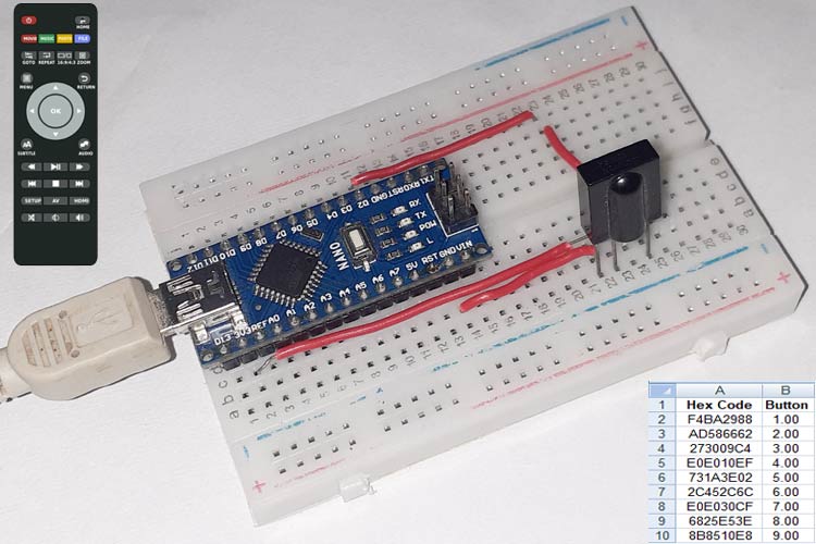
looks like you need a line decode_results results to store the results
then you need to pass the address of results to the decode function
like this
irrecv.decode(&results);
& is a used to "pass by reference" . you're sending the memory address of results to decode() so it can write in it.
you'll probably also have to pass results to your translateIR function, unless results is global.
void loop()   /*----( LOOP: RUNS CONSTANTLY )----*/
{
  decode_results results;
  if (irrecv.decode(&results)) // have we received an IR signal?

  {
    translateIR(results);
    irrecv.resume(); // receive the next value
  }
}/* --(end main loop )-- */

void translateIR(decode_results& results) // function with alot of the cases

{

  switch(results.value)

  {
  case 0xFFA25D: Serial.println("POWER"); break;
  case 0xFFE21D: Serial.println("FUNC/STOP"); break;
  case 0xFF629D: Serial.println("VOL+"); break;
  case 0xFF22DD: Serial.println("FAST BACK");    break;
  case 0xFF02FD: Serial.println("PAUSE");    break;
  case 0xFFC23D: Serial.println("FAST FORWARD");   break;
  case 0xFFE01F: Serial.println("DOWN");    break;
  case 0xFFA857: Serial.println("VOL-");    break;
  case 0xFF906F: Serial.println("UP");    break;
  case 0xFF9867: Serial.println("EQ");    break;
  case 0xFFB04F: Serial.println("ST/REPT");    break;
  case 0xFF6897: Serial.println("0");    break;
  case 0xFF30CF: Serial.println("1");    break;
  case 0xFF18E7: Serial.println("2");    break;
  case 0xFF7A85: Serial.println("3");    break;
  case 0xFF10EF: Serial.println("4");    break;
  case 0xFF38C7: Serial.println("5");    break;
  case 0xFF5AA5: Serial.println("6");    break;
  case 0xFF42BD: Serial.println("7");    break;
  case 0xFF4AB5: Serial.println("8");    break;
  case 0xFF52AD: Serial.println("9");    break;
  case 0xFFFFFFFF: Serial.println(" REPEAT");break;

  default: // i think this makes it so this will only print if no code matches
    Serial.println(" other button   ");

  }// End Case

  delay(500);


} //END of the variable
 jade lichen
Any folks here good with rotary encoders? I'm fairly new with them and already getting frustrated
I'm using Paul Soffregen's encoder library (https://github.com/PaulStoffregen/Encoder/blob/master/Encoder.h) and the example code works great! But as soon as I tryu to use its output to do anything other than report to the serial monitor (in this case, i'm just using it to modify drawn shapes on an oled display) I'm getting buggy output where it doesn't consistently recognize rotations or rotational direction.
 leaden ruin
RE: ArduinoISP
Why is it that PROG_FLASH and PROG_DATA don't actually do anything???
A: avrdude didn't use those commands, so they remain unimplemented.
 foggy ivy
I have an esp and its connected to a wifi, now i have also connected a phone to that same wifi. How can I get the IPO of the phone with in esp.
pine bramble
@jade lichen Encoders are subject to the kinds of bugs you're seeing.
It's going to take real effort to get it right. ;)
SAMD51 was said to have dedicated rotary encoder hardware.
 safe shell
foggy ivy
I have an esp and its connected to a wifi, now i have also connected a phone to ...
safe shell
foggy ivy
I have an esp and its connected to a wifi, now i have also connected a phone to ...
I don't know of a direct way. The assigned IP addresses are only within the purview of the Access Point. You could put the ESP into monitor mode and sniff the traffic to the AP and see what is connected.
That becomes fairly involved, may be easier to get the phone IP directly and supply it to the ESP in some more manual way.
If you have control of the router, you could use DHCP reservations to have predictable IP addresses - this is probably the easiest way (but this won't work if the phone is doing MAC address randomization)
You could ping IP ranges and make an educated guess. Or port scan in hopes of finding a fingerprint that is characteristic of the phone. But the phone may not react to pings or any port activity, so this is involved and may not work.
 visual spire
Is there a way to drive a passive buzzer with a PCA9685, which is a PWM driver ic?
shadow spoke
foggy ivy
I have an esp and its connected to a wifi, now i have also connected a phone to ...
Ping the whole subnet and find the IP address associated with the MAC address that belongs to the phone
safe shell
ping won't give MAC, but could use arp -a
 covert flare
Hi guys, I'm using a DHT22 sensor and an ESP32 board - the issue I'm having is that I'm getting nan readings
Code:
// or ethernet clients.
#include "config.h"

/************************ Example Starts Here *******************************/
#include <Adafruit_Sensor.h>
#include <DHT.h>
#include <DHT_U.h>

// pin connected to DH22 data line
#define DATA_PIN 2

// create DHT22 instance
DHT dht(DATA_PIN, DHT22);

// set up the 'temperature' and 'humidity' feeds
AdafruitIO_Feed *temperature = io.feed("temperature");
AdafruitIO_Feed *humidity = io.feed("humidity");```void setup() {
// start the serial connection
Serial.begin(115200);
// wait for serial monitor to open
while(! Serial);
// initialize dht22
dht.begin();
// connect to io.adafruit.com
Serial.print("Connecting to Adafruit IO");
io.connect();
// wait for a connection
while(io.status() < AIO_CONNECTED) {
Serial.print(".");
delay(500);
}
// we are connected
Serial.println();
Serial.println(io.statusText());
}
void loop() {

  // io.run(); is required for all sketches.
  // it should always be present at the top of your loop
  // function. it keeps the client connected to
  // io.adafruit.com, and processes any incoming data.
  io.run();

  int readData = dht.read(DATA_PIN); // Reads the data from the sensor
  float t = dht.readTemperature(); // Gets the values of the temperature
  float h = dht.readHumidity(); // Gets the values of the humidity

  if (isnan(h) || isnan(t)) {
    Serial.println(F("Failed to read from DHT sensor!"));
    return;
  }

  // Printing the results on the serial monitor
  Serial.print("Temperature = ");
  Serial.print(t);
  Serial.print(" *C ");
  Serial.print("    Humidity = ");
  Serial.print(h);
  Serial.println(" % ");

  delay(2000); // Delays 2 secods, as the DHT22 sampling rate is 0.5Hz

}
Output:
15:21:36.093 -> Failed to read from DHT sensor!``` quartz furnace
@covert flare hey what make ESP32 board are you using and can post a picture of the wiring ?
rough torrent
Hey there I'm trying to record audio using the Teensy audio library but I'm unable to even open files using the Arcada library. This is my test code: http://txt.do/18v6v
Here's the output from the serial monitor:
19:42:57.659 -> Arcada file test - tests reading and writing files
19:42:58.860 -> Trying SD Card filesystem
19:42:59.184 -> SD card found
19:42:59.184 -> QSPI filesystem found
19:42:59.184 -> QSPI flash chip JEDEC ID: 0xC84017
19:42:59.184 -> Mounted filesystem(s)!
19:42:59.184 -> Found filesystem!
19:42:59.184 ->     ArcadaFileSys : Exists? '/test.txt'
19:42:59.184 ->     ArcadaFileSys : open abs path '/test.txt'
19:42:59.184 -> Writing to 'test.txt'...
19:42:59.184 ->     ArcadaFileSys : open abs path '/test.txt'
19:42:59.184 -> Failed to open file
And then it stops. I've tried re-formatting the uSD card with FAT32 and erasing and rewriting CircuitPython on the QSPI - it still doesn't work.
(Please ping if you have any questions or such)
 foggy birch
covert flare
```cpp
void loop() {
// io.run(); is required for all sketches.
// it shoul...
foggy birch
covert flare
```cpp
void loop() {
// io.run(); is required for all sketches.
// it shoul...
why are you checking for nan? i just did something with a dht11. I would get rid of that if isnan statement and just see what dht.readtemperature says before throwing logic on it
covert flare
quartz furnace
<@174904441160466432> hey what make ESP32 board are you using and can post a ...
Sorry, I figured out the issue. hardware issue with the pins
quartz furnace
Ahh cool, glad you got it working !
covert flare
I was checking for nan to determine if there was an issue with my readings specifically, for many other demos I've seen the same thing with the humidity sensor!
hey sam, I have another question. mind if I fire?
quartz furnace
I’ll take a stab at it sure .. not an expert but I have set up several DHT11 & DHT22s for monitoring pet Geckos
covert flare
Oh this is for an LED and a photocell
quartz furnace
Sure .. I’ll still see if I can help
covert flare
I need to program something that does the following from an ESP32 Feather Huzzah set up with a photocell and an LED
- On/Off button to ESP32 & Dashboard which controls the LED; reads on/off signal, toggles LED.
- Reads photocell input, sends it an Adafruit dashboard and relevant feed.```I have a feeling I'll need to use the MQTT library and use subscriptions to get information of the state of the switch on my Adafruit dashboard.
Then, depending on the state, it changes the LED_PIN's value to high or low, which in turn affects the photocell's input, right?
quartz furnace
Clarifying questions: so two different feed names in this project? And the LED and the photocell are both on the same ESP32 Feather?
covert flare
Apologies, yes, two different feed names in the project.
LED - onoff
Photocell - photocell
Both are on the ESP32 Feather.
quartz furnace
So the LED is for a visual when your near the ESP32 and the feed is for remote viewing?
How often does the photocell need to be checked ? Are you doing values every few seconds or minutes or just looking for a big value change/ hits a threshold
covert flare
Right, unfortunately I'm doing it remotely since I can't get to campus.
It's being checked roughly every 5 seconds to avoid throttle.
Here's my circuit diagram!
 quartz furnace
Checking out the photo
Ahhh so the photocell is more for “ confirmation” that the LED did indeed toggle ? In a dark enough environment
covert flare
Exactly, yeah.
I believe so. Here's my simplistic dashboard, which I think I didn't mess up on:

The photocell feed should probably be a gauge.
quartz furnace
Neat project! Is this a guide you drafted or are one you are following from someone? My only thought is maybe a color sensor vs a photocell so you know for sure the LED (red) is on or not
But I’d point you to the digital example and the analog example
Appears to be the Ardunio example you are doing based on the code provided earlier
covert flare
There's no guide at all haha...
quartz furnace
Have you seen this GitHub page...

GitHub
Arduino library to access Adafruit IO from WiFi, cellular, and ethernet modules. - adafruit/Adafruit_IO_Arduino
That would be for the LED toggle
This one for the photocell
GitHub
Arduino library to access Adafruit IO from WiFi, cellular, and ethernet modules. - adafruit/Adafruit_IO_Arduino
covert flare
Ahhhhhh, thanks! I think I'm getting it.
covert flare
Is this therefore without using MQTT?
Also, what's the advantage of using, let's say, analog->save(current); over MQTT publish() definition?
quartz furnace
GitHub
Arduino library to access Adafruit IO from WiFi, cellular, and ethernet modules. - adafruit/Adafruit_IO_Arduino
I’ve always just used regular IO
I think MQTT has less “ dependencies”
Could be off .. someone else might be better to fact check that and answer
covert flare
That would make sense since it's dedicated for dashboard-hardware communication.
AdafruitIO_Feed *digital = io.feed("digital"); The 'io.feed()' part, does this create a new feed or just connect to an existing one?
I'm trying to find a definition reference as we speak haha
quartz furnace
It will create one of “digitally”
Does not already exist .. you can go and change all of the digitals to LED if you prefer
Ahh Digital not digitally
iPhone last second automatically change
Mention me if you have additional thoughts.. I’ll be around but a little bit of multitasking.. and bed before to long
Super cool project
covert flare
Thanks a lot sam, I'll give it a shot when I wake up! You've been really helpful.
quartz furnace
No problem happy to help.. I’ve gotten a lot of help on here and happy to give back!
 sharp siren
Hi! Anyone familiar with OLED displays? I've got a 256x64 ssd1322 and I can't get it to show anything. I'd appreciate some help 😄 !
 jovial nacelle
sharp siren
Hi! Anyone familiar with OLED displays? I've got a 256x64 ssd1322 and I can't ge...
jovial nacelle
sharp siren
Hi! Anyone familiar with OLED displays? I've got a 256x64 ssd1322 and I can't ge...
I'm new as well but got a 128x32 working.
It worked about like that:
- Connect to i2c pins.
- Install u8g2 library
- Initialize display
- display stuff
sharp siren
@jovial nacelle Thanks for your answer, I've an SPI one, from what I see it's correctly wired, I have u8g2 library, I upload an exampe sketch but the screen stays dark.
I've created an issue on u8g2 github page, you can follow maybe someone would answer and ours problems would be solved 😄 !
jovial nacelle
That's just the right way to get the dev angry...
Have you read up on this stuff and looked at some tutorials?
with the i2c display I had to get the adress of the display, then initialize it, set content then display.draw()
sharp siren
I've spent around 10 hours looking on every possible solution, nothing.
I have a smaller oled that works with i2c, it was a little hard but I got it working too.
The SPI one didn't even turn one pixel ....
 hollow bloom
Does anyone know how to tell if a ESP32 (Huzzah32) is running off battery power or USB? I want to collect data while running on battery, but connect to wifi and upload only when on usb power. I am monitoring battery voltage on A13 and shutting down when necessary, but cant find a way to tell if USB is connected.
I tried monitoring VBUS, but that only drops to 3.3v when disconnected. Not what I expected. I could monitor the change from 5v to 3.3v, but seems hacky. 😉
pine bramble
I see christopher embedded in that nick ;)
hollow bloom
pine bramble
_I see christopher_ embedded in that nick ;)
Christoph actually. My mom never liked that I shortened it online.
pine bramble
Yeah they don't like that.
Mine's a dactyl so it works for certain situations.
Malachai Mulligan .. two dactyls! -James Joyce
 grand basin
More of a general microcontroller question, but I want to connect the PWM output into the the analog input of the same Arduino, with a simple low pass filter inbetween. Is there any sort of feedback or electrical issues I should know about?
 steady moat
Im trying to make a arduino mini control a small e-ink or oled display and have to whole project run off solar power with no battery. just switch on when theres enough light. If anyone has experience or any pointers on this please let me know 🙂
Ive made this peice before. but this is not solar powered..

Artwork By Oliver Dorman 'Futhark six' 2017 Paper, Pencil, Gouache, Hand-carved Beech-wood, Cherry-wood, Glass, Electronics (OLED, Arduino-UNO)
 toxic bough
Hi!
Is there a way I can make a face detection using arduino?
My project is about counting the number of faces using arduino microcontroller. Is it possible?
 odd fjord
@toxic bough There are many examples available via a Google search.
@toxic bough looking at them, I have no idea what microcontroller and camera you have so I can't tell if they are useful examples. Hopefully someone with more Arduino experience can help.
 opaque matrix
@toxic bough there is a good chance that standard arduino boards won’t be fast enough to detect faces. Maybe some of the higher end ones might be able to, otherwise stepping up to something like a raspberry pi might be a better idea.
odd fjord
I have experimented with this "person detection" example, but it required a much more powerful microcontroller (Nano 33 Sense). https://www.element14.com/community/community/project14/nano-rama/blog/2020/04/29/tinyml-on-arduino-nano-33-ble-sense-person-detection-with-ble
toxic bough
odd fjord
<@!346995148124717058> looking at them, I have no idea what microcontroller and ...
Sir, I have an esp32 camera, arduino mega and nano, and raspberry pi 4
I'm thinking of having a serial communication between rasp and arduino. I'll be using the rasp as facial detection and send the data to arduino. Is it also possible?
odd fjord
@toxic bough I'm sorry, I do not know if it is possible or not. Hopefully someone else with more experience can comment.
 junior forge
toxic bough
I'm thinking of having a serial communication between rasp and arduino. I'll be ...
junior forge
toxic bough
I'm thinking of having a serial communication between rasp and arduino. I'll be ...
Serial from raspi to arduino is possible. If you google "serial raspberry pi to arduino" you'll find a few examples
toxic bough
Thank you, sir!!
rough torrent
Although it might just be easier to do everything on the Pi instead of figuring out a communication protocol between the Arduino and Pi
There's also this - but it uses MicroPython instead of CircuitPython: https://www.adafruit.com/product/4478

The OpenMV Cam is like a super powerful microcontroller board with a camera on board that you program in MicroPython. It's easy to run machine visions algorithms on what the OpenMV ...
 lone heart
does anyone know if arduino nano 33 ble has a Not Connected Pin like Uno?
 junior forge
what are you trying to do? I'm not really clear on what you'd use one for
lone heart
Grove GSR
with Analog signal (yellow), 3V3/5V VCC (red) and GND (black) and a white wire saying NC
@junior forge
junior forge
think you just ignore that one then
lone heart
kk
junior forge
looks like they used some stock 4-pin connector and only needed 3, so one is NC
@lone heart doesn't connect to anything here https://media-cdn.seeedstudio.com/media/catalog/product/cache/9d0ce51a71ce6a79dfa2a98d65a0f0bd/h/t/httpsstatics3.seeedstudio.comseeedimg2016-11o16fm3f0lplsh4kl18m236ec.jpg
 lone heart
Noice
 quick hornet
NC means "not connected"
 vivid rock
Reminds me of an old joke about a programmer who, when going to bed, sets two glasses next to him: one with water - in case he gets thirsty during the night - and one empty: in case he doesn't
lone heart
Are there any good rechargeable batteries to use with the Nano BLE board?
junior forge
lone heart
Are there any good rechargeable batteries to use with the Nano BLE board?
any lipo should be fine
lone heart
i know the box said minimum was 4.5V, most lipos i see are like 3.7
 raven vale
this is probably not the exact right place for this question, but I'm not sure if there is a better one: On the new Feather RP2040, what GPIO pin is the built in NeoPixel attached to for use under c++?
is it 8 like everything else? I don't see it in the documentation
junior forge
lone heart
i know the box said minimum was 4.5V, most lipos i see are like 3.7
I've run one off of a 3.7v 18650. But you can also get a boost converter to keep it at a solid 5v
lone heart
here...itll be easier to show the circuit idea
junior forge
raven vale
this is probably not the exact right place for this question, but I'm not sure i...
#help-with-rp2040-pio is probably better
lone heart

im not sure if i even put the connections in the right place
the sensors work off of 5V or 3V3, doesnt matter
each sensor is analog SIG, Vcc and GND
junior forge
looks fine
raven vale
junior forge
<#803084483975839744> is probably better
probably right. I'll ask there too thanks. It's not PIO related and I figured if arduino core had been released this would be the same answer as if I were using that, but point taken
lone heart
would I be able to stream data from the sensors via Bluetooth to a Serial monitor or app or something
with that BLE module
junior forge
Can't see why not. That's the main point of the board
junior forge
It's supposed to be too low, but it did work when I was using it. The batteries do start out above 3.7v when fully charged, though
A boost converter like these would keep it at 5v to be safe https://www.amazon.com/Organizer-Step-Up-Adjustable-Switching-Converter/dp/B07WRX2LZ7/
although I didn't run it for a super long time. Just an hour or so
And I've since added the boost
pine bramble
@raven vale GPIO16on RP2040 is labeled NEOPIX on the Feather RP2040 schematic diagram.
https://learn.adafruit.com/assets/100337
Cells C3 and D3-D4.
WS2812B is the p/n for the RGB led.
GPIO13 is mapped to (Arduino) D13 and is a red LED on the board.
raven vale
pine bramble
<@!248264531606765568> `GPIO16`on `RP2040` is labeled `NEOPIX` on the Feather RP...
Thanks @pine bramble
pine bramble
;)
 gilded cargo
Hi all, im a bit of a novice so this might come off as a stupid question. 😂
What is the best practice for "building a line of text"? Say I want to print some text to serial and display, but I want to postfix it based on a condition, how do I save the string(?) im building?
Can I just;
void COM_Message(bool a) {
String msg = "A is ";
if(a) msg += "true.";
else msg += "false.";
Serial.println(msg);
}
Or will this cause issues with memory or something? I think I read storing a string is almost always a bad idea, but not sure why that was..
rough torrent
The original Strings will eat your RAM because it uses dynamic memory allocation. There is a SafeString library that does the same thing, but as the name implies it "safer." You can find the SafeString library in the library manager.
vivid rock
which mcu are you using and how many strings do you intend to store?
gilded cargo
Arduino Mega, and I think one? Im just building a line of text in a void and pushing it out at the end.
rough torrent
Will this be run in a loop?
Because if it does, that increases the chance of running out of memory. If you do it once, it shouldn't hurt.
vivid rock
then i do not think you will have any problems even using original String library
gilded cargo
it gets run on command a few times, about once or twice a minute. At the moment im just doing Serial.print(); with a Serial.Println(); to push it out, but id like to store the entire line so I can also push it out to my OLED display.
im currently already on 55% dynamic memory used
there is a large timeschedule array eating up most of it, but id like to try and be conservative on memory since im far from done. :'3
vivid rock
this may help:
The Arduino programming language Reference, organized into Functions, Variable and Constant, and Structure keywords.
gilded cargo
Hmm, this would constrain the amount of string memory being used?
Thats interesting, it bounds the string to x amount of bytes?
vivid rock
afaik, it allocates some memory to be used for string manipulations, and as long as your strings fit within that buffer, tgere will be no need to allocate more memory.
but i nay be mistaken
gilded cargo
What happens when the string goes out of bounds? it just cuts off the end? No big deal for my purpose, but it does prevent it from blowing up. 😛
vivid rock
if your strings do not fit, i expect the sketch will allocate more memory
gilded cargo
Its like a char array but less annoying. 😗
oh it will? then that kinda defeats the point of reserve() I think.
well I guess it makes sense, it reserves but doesnt restrain
vivid rock
the point is that normally when you make a 5 symbol String, mcu allocates enough memory for 5 symbols
you add another symbol, it allocates new chunk of memory, enogh for 6 symbols, and copies over, freeing previous chunk
gilded cargo
oh ok, so its not a preset size for String. It just grows fatter if you feed it?
vivid rock
if you reserve(), then afaik it allocates given block of memory, saving the need to reallocate and copy
as long as you do not grow too large
if you do, then it will have to reallocate
gilded cargo
its not like uint8_t where you know that thing will be THIS size. ok, yea then I see a need for reserve();
Thank you clarifying.
vivid rock
i might be wrong, of course - need to double-check this
gilded cargo
I was already working on testing it in practice, and im having some weird thing come out.
void setup()
{
String banana = "Hello World";
Serial.begin(74880);
while (!Serial) delay(10);
Serial.print("banana is ");
Serial.print(sizeof(banana));
Serial.print(" bytes");
}void loop(){}
The outcome always seems to be 6 bytes. no matter howmuch I dump into banana
vivid rock

C++ for Arduino
In many Arduino programs, the String class is a major cause of inefficiency. We’ll see how to improve our code when using this class.
because sizeof probably gives you size of the pointer, or something like this - not real size of object
gilded cargo
oh rats, you're right. hmm
gilded cargo
Those 8 tips are super helpful, thanks @vivid rock
 night portal
Random question based on experience I had on reddit. Are you able to control Neopixels with boards like Feather or QT PY that use 3.3V logic?
junior forge
night portal
Random question based on experience I had on reddit. Are you able to control Ne...
If you power them with 3.3v, then yeah
night portal
junior forge
If you power them with 3.3v, then yeah
So their data pins and power pins have to match in voltage in order to work?
junior forge
night portal
So their data pins and power pins have to match in voltage in order to work?
yup
you can use a level shifter to change the 3.3v logic to 5v
night portal
junior forge
you can use a level shifter to change the 3.3v logic to 5v
Ah okay, gotcha. Thanks!
junior forge
night portal
Ah okay, gotcha. Thanks!
Hmm, their guide says to use the 5v https://learn.adafruit.com/qt-py-and-neopixel-leds/qt-py-neopixel-wiring
 night portal
junior forge
Hmm, their guide says to use the 5v https://learn.adafruit.com/qt-py-and-neopixe...
night portal
junior forge
Hmm, their guide says to use the 5v https://learn.adafruit.com/qt-py-and-neopixe...
See that's where I got confused too. I had success with powering the neopixels at 5V externally, and sending data pin to the QT PY. This is more like a general question, then trying to get something to work
junior forge
night portal
See that's where I got confused too. I had success with powering the neopixels ...
well... if it works, then great! Don;'t know how the A3 is different, but in my experience with the digital pins I needed to match voltage
but yeah, knowing WHY would be even better
night portal
junior forge
well... if it works, then great! Don;'t know how the A3 is different, but in my ...
welllll it works.... but only in certain config. I'm having some really strange experiences with my project currently, but they seem to be different issues than matching logic based on what you and I have been talking about lol
junior forge
When I had them mismatched I would sometimes get it to work, sometimes have it flicker, sometimes the colors would be off, and sometimes nothing would go out at all
it was maddeningly inconsistent
night portal
junior forge
it was maddeningly inconsistent
mine will work when LEDs are powered by external 5V supply, and the QTPY is powered with dekstop USB port, but will not work properly when they are both powered by the same 5V power supply using a splitter. No clue why that is
vivid rock
In my experience, there are two reasonably safe ways:
- use 5V to power neopixels, and use level shifter to shift voltage of logic pin of a 3.3v board (some adafruit boards include such level shifter on-board - exactly for this purpose)
- use a LiPo battery (nominal voltage 3.7v, actual voltage ranges from 4.2 to 3.2) to power neopixels, use 3.3v logic pin for control
Second method might have the problem that neopixel colors might change as battery voltage changes, so it is not advised if faithful color reproduction is important to you
night portal
vivid rock
In my experience, there are two reasonably safe ways:
- use 5V to power neopixe...
Thanks for the advice! I've got a QTPY arriving today since I made a really dumb mistake when trouble shooting and burned out the first one. But I'm definitely going to try using a level shifter so that I can match all voltages. Hopefully that will fix my issue
 elfin dune
I have seen an Adafruit board that includes a 5v logic pin for Neopixel data, but I haven't been able to find it. Do you all know what boards would have that?
junior forge
elfin dune
I have seen an Adafruit board that includes a 5v logic pin for Neopixel data, bu...
Hmm, the Metro does, but it's not small https://www.adafruit.com/product/2488

This is the Adafruit METRO Arduino-Compatible - with headers. It's a fully assembled and tested microcontroller and physical computing board with through-hole headers ...

Make your Arduino-based project tiny and with the Adafruit METRO Mini! The METRO Mini works great with the Arduino IDE, and runs the ATmega328P at 16MHz so it is pin-compatible with Arduino ...
itsybitsy https://www.adafruit.com/product/3677

What's smaller than a Feather but larger than a Trinket? It's an ItsyBitsy! Small, powerful, Arduino-compatible - this microcontroller board is perfect when you want something very ...
elfin dune
thanks @junior forge .. I keep thinking there was a 3.3v logic Adafruit board that had a single pin that was 5v logic shifted specifically for Neopixel
junior forge
elfin dune
thanks <@!520351898415661076> .. I keep thinking there was a 3.3v logic Adafruit...
ah, gotcha. don't know
elfin dune
But I haven't been able to find it since, and now think maybe I imagined it. 🙂
I have used the neopxl8 feather wing for both dma and 5v logic shifting, but a built in one would be nice since many of these boards have DMA built in already
I found it! the ItsyBitsy M4 https://www.adafruit.com/product/3800
"1 x Special Vhigh output pin gives you the higher voltage from VBAT or VUSB, for driving NeoPixels, servos, and other 5V-logic devices. Digital 5 level-shifted output for high-voltage logic level output."
What's smaller than a Feather but larger than a Trinket? It's an Adafruit ItsyBitsy M4 Express featuring the Microchip ATSAMD51! Small, powerful, with a ultra fast ATSAMD51 Cortex ...
junior forge
oh, right this one too https://www.adafruit.com/product/4481

What's smaller than a Feather but larger than a Trinket? It's an Adafruit ItsyBitsy nRF52840 Express featuring the Nordic nRF52840 Bluetooth LE processor! Teensy & powerful, ...
elfin dune
Whew, that was really bugging me. 🙂
junior forge
Didn't really understand what that meant before
But that's nice for a future use with LEDs
elfin dune
Yeah for sure. My current project is using both capsense and LEDs, unfortunately these don't have the SAMD21's capactive touch pads, so either way I'm using an additional chip. Personally I'll probably stick with QT Py and use a level shifter
junior forge
So how do you address that pin in CP?
elfin dune
But if you are doing a straight forward neopixel project, one of those boards would be really handy
elfin dune
junior forge
So how do you address that pin in CP?
I haven't done it before, but I assume its just like any other pin, just voltage shifted for you.
junior forge
right, just identifying it
elfin dune
yeah, cool thing about that itsyBitsy M4 is it has DMA support on the 5v logic pin, so it plays a lot better with interrupts etc.
 junior forge
ahhh "#5 - GPIO #5. This is a special OUTPUT-only pin that can PWM. It is level-shifted up to Vhi voltage, so its perfect for driving NeoPixels that want a ~5V logic level input. You can use this with our NeoPixel DMA control library to automatically write NeoPixel data without needing any processor time."
So D5 is the pin
elfin dune
Yeah handy, that
That makes that itsyBitsy M4 the real champ for basic neopixel projects
I wish the QT Py had that too
elfin dune
I wonder what they do for the built-in NeoPixel, if it is level-shifted or if they just run it at 3.3v
(the built in one on the QT Py that is)
odd fjord
@elfin dune according to the schematic, the QTPY neopixel is powered directly from a GPIO Pin, so 3.3V https://cdn-learn.adafruit.com/assets/assets/000/095/390/original/adafruit_products_QTPy_sch.png?1602007604
 green thunder
I've done several projects with QT Py and NeoPixels now and I can share a few of my findings from these. First is that's okay if the signal is 3.3v as long as the NeoPixel power source is 3.3 (or close) as well. If you power with 5v but provide a 3.3v signal, you are leaving a lot to chance. For my own projects, I only use 3.3v power and signal if it is a low-power project that I can power directly from a USB port (i.e. < 500 mA peak draw). Otherwise, I power my NeoPixels with an external power source, and use a level shifter with the QT Py to shift the signal voltage (I just bought a pack of like 20 level shifters from Amazon, I use them so frequently I'm almost out lol). Secondly, and perhaps less well known, is that you can actually use DMA NeoPixels with the QT Py as well. It comes with a cost: you have to either give up the SPI peripheral (DMA uses the MOSI pin in this case), or give up the optional flash chip and solder the signal wire to pin 16 on the bottom QSPI pads, as these are the only 2 pins exposed for DMA NeoPixels on the QT Py.
elfin dune
odd fjord
<@!257766195095273472> according to the schematic, the QTPY neopixel is powered ...
Interesting it's powered from a GPIO pin too
elfin dune
green thunder
I've done several projects with QT Py and NeoPixels now and I can share a few of...
thanks! I think I might just drive them at 3.3v to avoid the potential issue. I'm only using 4 "pixels" for this one anyway, and while brightness and color is good, it's not critical.
green thunder
You should be good then 😃 Usually in the projects where I'm just using a few pixels, I also intend for the user to be looking directly at them from close up, so the limiting factor usually ends up being trying not to blind myself rather than trying not to draw too much power 😂
elfin dune
green thunder
You should be good then 😃 Usually in the projects where I'm just using a few pi...
yeah, these things can get bright! In this case, I'm going to be using the black LED acrylic on top. I'm experimenting with proximity capsense to make glowing "buttons" on a smooth surface that change color when touched.
green thunder
That sounds like a neat project!
elfin dune
Thanks! I have seen it done with single color LEDs, but not RGB. I'm thinking it would be great both for interface buttons, as well as a panel of them would be fun to play with
green thunder
I recently got some of the black LED acrylic too and it's been really fun to play with! When you get it working please show it off in the #show-and-tell channel, I would be very interested in seeing the results 😄
elfin dune
green thunder
I recently got some of the black LED acrylic too and it's been really fun to pla...
absolutely! I've only designed and made one other PCB before, and capsense is a little tricky, but I'm just taking my time and learning a lot as I go
junior forge
the black acrylic definitely takes a project from workbench pretty to living room pretty
green thunder
It's so cool 
gilded cargo
How many servos can an arduino pro mini control (not power) with the servo library? I am trying to see if I can use one to decode a PPM signal to break out to individual outputs. My receiver has a 12 channel PPM block, and im wondering if I could make full use of that.
I only need 4 full control channels, the rest can be on/off outputs.
covert flare
@quartz furnace No matter the state of my button, I'm being told that the feed output is '0' or 'OFF'
#define LED_PIN 12

// set up the 'digital' feed
AdafruitIO_Feed *digital = io.feed("onoff");

void setup() {

  pinMode(LED_PIN, OUTPUT);

  // start the serial connection
  Serial.begin(115200);

  // wait for serial monitor to open
  while(! Serial);

  // connect to io.adafruit.com
  Serial.print("Connecting to Adafruit IO");
  io.connect();

  // set up a message handler for the 'digital' feed.
  // the handleMessage function (defined below)
  // will be called whenever a message is
  // received from adafruit io.
  digital->onMessage(handleMessage);

  // wait for a connection
  while(io.status() < AIO_CONNECTED) {
    Serial.print(".");
    delay(500);
  }

  // we are connected
  Serial.println();
  Serial.println(io.statusText());
  digital->get();

}
void loop() {

  // io.run(); is required for all sketches.
  // it should always be present at the top of your loop
  // function. it keeps the client connected to
  // io.adafruit.com, and processes any incoming data.
  io.run();

}

// this function is called whenever an 'digital' feed message
// is received from Adafruit IO. it was attached to
// the 'digital' feed in the setup() function above.
void handleMessage(AdafruitIO_Data *data) {

  Serial.print("received <- ");

  if(data->toPinLevel() == HIGH)
    Serial.println("HIGH");
  else
    Serial.println("LOW");

  Serial.println(data->toPinLevel());
  digitalWrite(LED_PIN, data->toPinLevel());
}```I added this bit Serial.println(data->toPinLevel()); to see what was being passed through from my Adafruit dashboard to the Arduino, and no matter what the state is, it outputs '0'!
quartz furnace
So I see two different feeds Digital and onoff
On your code after you define the pin
I’ll have to look at it more here in a bit .. trying to read on an iPhone
covert flare
Ah, thanks! You been doing alright?
covert flare
Figured it out!
opaque matrix
@elfin dune Looks like the rp2040 ItsyBitsy has a level shifted pin as well
It also has the pio cores which are extremely good at driving nepixels
I think the level-shifted pin is a feature of all of the ItsyBitsy models 😄
opaque matrix
Just had a check and they all have pin 5 level shifted except the 32u4 5V because its already at the required voltage
I might grab one as I'm currently powering my neopixels though a diode to drop the voltage down enough
 sand charm
So I have a knock off arduino uno
And it’s not showing up on windows at all
The green led on it only turns on for a second when plugged in
rough torrent
Have you tried switching cables and usb ports?
 umbral basalt
Does switching an led on and off fast with an arduino consume less power? multiple times at 60Hz would that consume less power?
 shrewd solstice
Hi everyone I'm still pretty new to this stuff, so bear with me. I need a little help in how to troubleshoot a problem with a new sk2812 LED strip. First time plugging it up, and only 23 modules are lit in the 1m strip. The whole point for choosing sk2812 was that it would pass the signal if one module were blown, so I don't understand why this would happen.
Driver is a NodeMCU running Tasmota for the moment. Power is +3.3 pin.

Just occurred I can try the contacts anywhere in the strip. Hmm.
umbral basalt
@shrewd solstice try changing the library you are using
gilded cargo
Im running into an annoying issue with the Adafruit_GFX library;
When I run
display.getTextBounds("AQUAMATIC STATUS", x, y, &x1, &y1, &w, &h);
w returns 124, which I think is incorrect. Letters are 6 wide, so shouldnt w be 95, since it should return total box width -1? Anyone know why this is happening?
 paper mist
hi guys, just installed the arduino ide on a new arch install on my desktop, but when i go to launch it, i get this error WARNING: An illegal reflective access operation has occurred WARNING: Illegal reflective access by processing.app.linux.GTKLookAndFeelFixer (file:/usr/share/arduino/lib/arduino-core.jar) to field com.sun.java.swing.plaf.gtk.GTKLookAndFeel.styleFactory WARNING: Please consider reporting this to the maintainers of processing.app.linux.GTKLookAndFeelFixer WARNING: Use --illegal-access=warn to enable warnings of further illegal reflective access operations WARNING: All illegal access operations will be denied in a future release java.lang.NullPointerException at processing.app.Base.rebuildProgrammerMenu(Base.java:1705) at processing.app.Base.<init>(Base.java:286) at processing.app.Base.main(Base.java:150)
i installed it with the arduino package and have tried running it with both openjdk 11 and 15, neither work, both give the same error
it worked fine on my previous install and i don't remember having to do anything weird to get it working
any ideas?
pine bramble
i keep getting this error, any ideas?
`Arduino: 1.8.12 (Windows 10), Board: "Arduino Uno"
Sketch uses 4354 bytes (13%) of program storage space. Maximum is 32256 bytes.
Global variables use 482 bytes (23%) of dynamic memory, leaving 1566 bytes for local variables. Maximum is 2048 bytes.
avrdude: stk500_recv(): programmer is not responding
avrdude: stk500_getsync() attempt 1 of 10: not in sync: resp=0xa2
avrdude: stk500_recv(): programmer is not responding
avrdude: stk500_getsync() attempt 2 of 10: not in sync: resp=0xa2
avrdude: stk500_recv(): programmer is not responding
avrdude: stk500_getsync() attempt 3 of 10: not in sync: resp=0xa2
avrdude: stk500_recv(): programmer is not responding
avrdude: stk500_getsync() attempt 4 of 10: not in sync: resp=0xa2
avrdude: stk500_recv(): programmer is not responding
avrdude: stk500_getsync() attempt 5 of 10: not in sync: resp=0xa2
avrdude: stk500_recv(): programmer is not responding
avrdude: stk500_getsync() attempt 6 of 10: not in sync: resp=0xa2
avrdude: stk500_recv(): programmer is not responding
avrdude: stk500_getsync() attempt 7 of 10: not in sync: resp=0xa2
avrdude: stk500_recv(): programmer is not responding
avrdude: stk500_getsync() attempt 8 of 10: not in sync: resp=0xa2
avrdude: stk500_recv(): programmer is not responding
avrdude: stk500_getsync() attempt 9 of 10: not in sync: resp=0xa2
avrdude: stk500_recv(): programmer is not responding
avrdude: stk500_getsync() attempt 10 of 10: not in sync: resp=0xa2
Problem uploading to board. See http://www.arduino.cc/en/Guide/Troubleshooting#upload for suggestions.
This report would have more information with
"Show verbose output during compilation"
option enabled in File -> Preferences.
`
leaden ruin
Which COM port is your Arduino Uno using?
covert flare
@quartz furnace Finished result!
https://puu.sh/Hp2l6/ff6e8c1d43.mp4
gilded cargo
I'm trying to build a memory wipe function in my code, but im not having much luck, for some reason the EEPROM byte changes before I write to it. I have this;
void setup() {
uint8_t MEM_Reboot = 69; // Change to reboot EEPROM.
if (EEPROM.read(0) != MEM_Reboot) // Rebooting EEPROM?
{
EEPROM.write(0, MEM_Reboot); // EEPROM Rebooting.
// Do some stuff to EEPRPOM
}
}
But its not having it. When I test for EEPROM byte 0 prior to writing, its already reading identical to MEM_Reboot. I don't see my mistake here. Does anyone else understand whats going wrong?
leaden ruin
What board are you using?
gilded cargo
Mega
When I call EEPROM.read(0); even before the if statement, it has already changed to whatever ive set MEM_Reboot to.
there are no other parts of the code that write or roll over to byte 0. so im thoroughly confused. 
Because how does MEM_Reboot get into EEPROM.read(0) without me telling it to.
its like the if statement jumps the line somehow
when I comment out the write, it no longer instacopies MEM_Reboot to byte 0, so it DOES seem to jump the line? Some kind of stupid compile issue?
leaden ruin
So EEPROM.read(0) != MEM_Reboot is alway true?
gilded cargo
It appears to never pass that gate. I suspect a datatype mismatch. I will try something.
Its very strange, casting them both to the same datatype does not fix it, yet it does seem to execute the write...
#include <EEPROM.h>            // Memory control

void setup() {
  Serial.begin(74880);
  while (!Serial) delay(10);
  Serial.setTimeout(250);
  byte MEM_Reboot = 32; // Change to reboot EEPROM.
  Serial.println("MEM_Reboot says " + (String)MEM_Reboot);
  Serial.println("Byte 0 says " + (String)EEPROM.read(0));
  if ((byte)EEPROM.read(0) != MEM_Reboot) // Rebooting EEPROM?
  {
    Serial.println("Doink");
    EEPROM.write(0, MEM_Reboot);    // EEPROM Rebooting.
    // Do some stuff to EEPRPOM
  }
}

void loop() {
}
Heres the whole test script.
MEM_Reboot always appears in EEPROM.read(0) no matter what I seem to do. But it does NOT print 'doink'.
EEPROM.read(0) should at most retain the last number I assigned to MEM_Reboot, not the current.
shadow tusk
Hi @gilded cargo. Unfortunately, I don't have the knowledge to be able to help with your problem technically. However, what I can help with is making sure that your code snippet is easy to read as code.
If you enclose your code in triple backticks (or "grave" symbols), like below it'll display it nicely, and you can even specify which syntax to use for highlighting!
```c
#include <EEPROM.h>
void setup() {
// ....
}
```
gilded cargo
oh I didnt know you could do that, thanks!
shadow tusk
Yep, it's pretty handy
I just can't format the example to look right! Lol
Discord uses a lot of the Markdown syntax, such as for bold, highlighting, code elements and blocks, etc.
gilded cargo
oh wow, that looks somuch better, haha
shadow tusk
My biggest "like" of it is that it monospaces code - the syntax highlighting is a nice bonus 🙂
gilded cargo
yea you kinda lose flow when you quote or darkbox it. That makes it almost as readable as my editor.
This quantum byte has been haunting me for an hour now. I just cant get it to behave logically.
shadow tusk
Have you tried breaking out each Serial.println() and EEPROM.read() calls into separate operations? Then you could do a Serial.println(variable); without casting to a String
gilded cargo
ill give that a whack, one moment
shadow tusk
For example, this Serial.println("Byte 0 says " + (String)EEPROM.read(0)); would become
byte firstRead;
firstRead = EEPROM.read(0);
Serial.print("Byte 0 says ");
Serial.println(firstRead);
presaving the value doesnt seem to change anything, unfortunately.
 north stream
You say it shows the byte as MEM_Reboot and does not print doink, which is exactly what I would expect: the code only runs the doink block if the EEPROM byte is not MEM_Reboot
gilded cargo
yes, yet it always IS MEM_Reboot even when it shouldnt be.
north stream
I don't see any code that changes it to anything other than MEM_Reboot
gilded cargo
The point of this code is that it resets EEPROM whenever I change the flag. Then once its done that, I can reset the arduino and the first byte will always be that. It cant initialize an EEPROM reset unless I change the code itself.
Perhaps im mistaken; Does an arduino zero its EEPROM when you flash it?
north stream
No, it doesn't. You can use the avrdude program that loads the flash to also clear the EEPROM, but you would have to do so explicitly.
gilded cargo
ok, so what im trying to do atleast makes sense. I want to have the option to trigger the firmware to reload a preset to EEPROM, to make sure any changes made by the code previously have been erased.
north stream
I have actually done something like that, but with a different chip where it's easier to set up.
In your case, it's going to be somewhat trickier. I would look for some way to store the "I've been reflashed" flag in flash (so it's set when the code is loaded), and then have the code check the flash flag on startup, and if it's set, both clear the EEPROM and reset the flash flag.
gilded cargo
Its basically versioning. it checks if current EEPROM is the version I request, if not, it triggers a reset.
north stream
The hard part is arranging to store the flash flag in a flash page by itself, so it can be updated without affecting the rest of the code.
Ah, you can do that too, and it's actually easier: store a version code in the flash along with your program, and have the startup routine read that and the version code in EEPROM and compare them. If they don't match, clear the EEPROM and reset its version code.
gilded cargo
thats what im doing, by reserving byte 0 as a comparing byte. if it differs from flash it should set it to reflect flash, it should only be able to do this once if the flash value is a constant.
north stream
Correct.
gilded cargo
BUT it seems to jump the gun somehow, by making byte 0 reflect flash before comparing anything.
So thats what im scratching my head over
how does that flash byte already end up in EEPROM without me telling it to put it there.
north stream
It doesn't, so the problem reduces to determining why it appears to do so.
gilded cargo
So to reiterate;
#include <EEPROM.h>            // Memory control

void setup() {
  Serial.begin(74880);
  while (!Serial) delay(10);
  Serial.setTimeout(250);
  byte MEM_Reboot = 6; // Change to reboot EEPROM.
  Serial.println("MEM_Reboot says " + (String)MEM_Reboot);
  Serial.println("Byte 0 says " + (String)EEPROM.read(0));
  if (EEPROM.read(0) != MEM_Reboot) // Rebooting EEPROM?
  {
    Serial.println("Doink");
    EEPROM.write(0, MEM_Reboot);    // EEPROM Rebooting.
    // Do some stuff to EEPRPOM
  }
}

void loop() {
}
Produces this:
15:35:10.584 -> MEM_Reboot says 6
15:35:10.584 -> Byte 0 says 6
After changing the number prior to flashing it.
So EEPROM.read(0) is not pulling from where I assume it should be coming from.
OK, so I found something out, not sure what to do with that yet, BUT...
#include <EEPROM.h>            // Memory control

void setup() {
  Serial.begin(74880);
  while (!Serial) delay(10);
  Serial.setTimeout(250);
  byte MEM_Reboot = 8; // Change to reboot EEPROM.
  byte MEM_Pulled;
  EEPROM.get(0,MEM_Pulled);
  Serial.println("MEM_Reboot says " + (String)MEM_Reboot);
  Serial.println("Byte 0 says " + (String)MEM_Pulled);
  if (MEM_Pulled != MEM_Reboot) // Rebooting EEPROM?
  {
    Serial.println("Doink");
    EEPROM.write(0, MEM_Reboot);    // EEPROM Rebooting.
    // Do some stuff to EEPRPOM
  }
}

void loop() {
}
This seems to work.
using get instead of read, somehow works. why does it though..
shoving EEPROM.read(0) into MEM_Pulled seems to break it again.. what on earth is happening..
and now its broken again, aaaaaaa
making me wonder if I cooked my arduino or something.. how bizarre..
shadow tusk
I've been digging around for a USB-A cable to test on mine. I'm curious if looping through the first x bytes using .get() and .read() come up with the same valuesi
north stream
I suppose I could go round up an Arduino and try it
shadow tusk
And could doing the software reboot be doing something with the EEPROM?
shadow tusk
north stream
I suppose I could go round up an Arduino and try it
I've got the arduino if you've got the cable! 😄
north stream
I tried looking at the source code of the EEPROM library, but it's a little bewildering (read() uses an EERef structure, but get() uses an EEPtr structure)
gilded cargo
does tinkercad have that eeprom library?
north stream
I don't know: I didn't even know Tinkercad had Arduino interfacing ability
gilded cargo
its got a rudimentary simulation.
north stream
Oh, are you using an emulated Arduino?
north stream
I expect it would support the EEPROM calls, but may well not (correctly) support the non-volatile nature of EEPROM
gilded cargo
yeah thats what im gonna guess as well, lets see
well it does seem to think byte 0 is different when it boots up, but when I push the reset button it nolonger thinks so. so it is doing the thing. 😂
shadow tusk
Or at least it's doing A thing!
gilded cargo
well.. yeah. But not on MY arduino. 😅
This simulated UNO seems to know whatsup. but my dingy mega doesnt wanna play ball
or plays ball too eagerly, I should say.
could I be having some kind of goofed up compiler setting?
north stream
Interesting. There are ways to investigate the EEPROM contents directly, using the built-in device monitoring functionality, but you'd need a device programmer to talk to it (most Arduino bootloaders don't support interrogating the EEPROM)
There is a way to use a second Arduino as a device programmer to talk directly to the chip in debugging mode, but I don't know if that supports the EEPROM commands (I'm guessing it would, but I'm not sure).
gilded cargo
ive got some UART/ISP programmers kicking about to deal with pro minis but my knowledge of those doesnt go beyond "stick it in the little board and push go"
north stream
Ah, that would work. You should be able to connect the ISP programmer to the 6-pin programming port on the Mega and then use avrdude to read the EEPROM contents directly
I'm a fan of doing stuff like that to look at things directly when debugging wonky problems like this, even though it's a pain to wire everything up and figure out the arcane avrdude incantations to retrieve the information I'm looking for.
gilded cargo
hmm, well it appears its a TTL programmer. Thats something else entirely I think.
north stream
Ah, that's probably something like a USB to serial adapter to talk to boards that don't have their own USB chips. Not quite the same thing as an ISP
gilded cargo
ive got another but ive lost documentation and honestly have no clue what it ACTUALLY is. 😂
north stream
If it has a little rectangular 2x3 pin connector, it's probably an ISP
gilded cargo


Whatever it is this thing passes for. :'3
it has miso mosi but other than that..
Its got a pretty light when I plug it in. 😂 Let me see what device manager makes of it
well it appears to be XWUSBASP
USBasp then
it should be able to do the thing. now I have to go find out what AVRdude is. 😂
isnt that already baked into IDE somewhere?
Its not coming up with a comport when I plug it in, so im not sure if this thing is 100%. 
If somebody could toss that code on a spare arduino somewhere to see if it works for them, that would be grand. 😅 If it does, id know if theres an actual point to me struggling with AVRdude. Ill keep trying. 😛
pine bramble
leaden ruin
Which COM port is your Arduino Uno using?
com 6
leaden ruin
Do you have anything connected to the Arduino?
pine bramble
yeah i have a mini connected let me show you what im trying to do
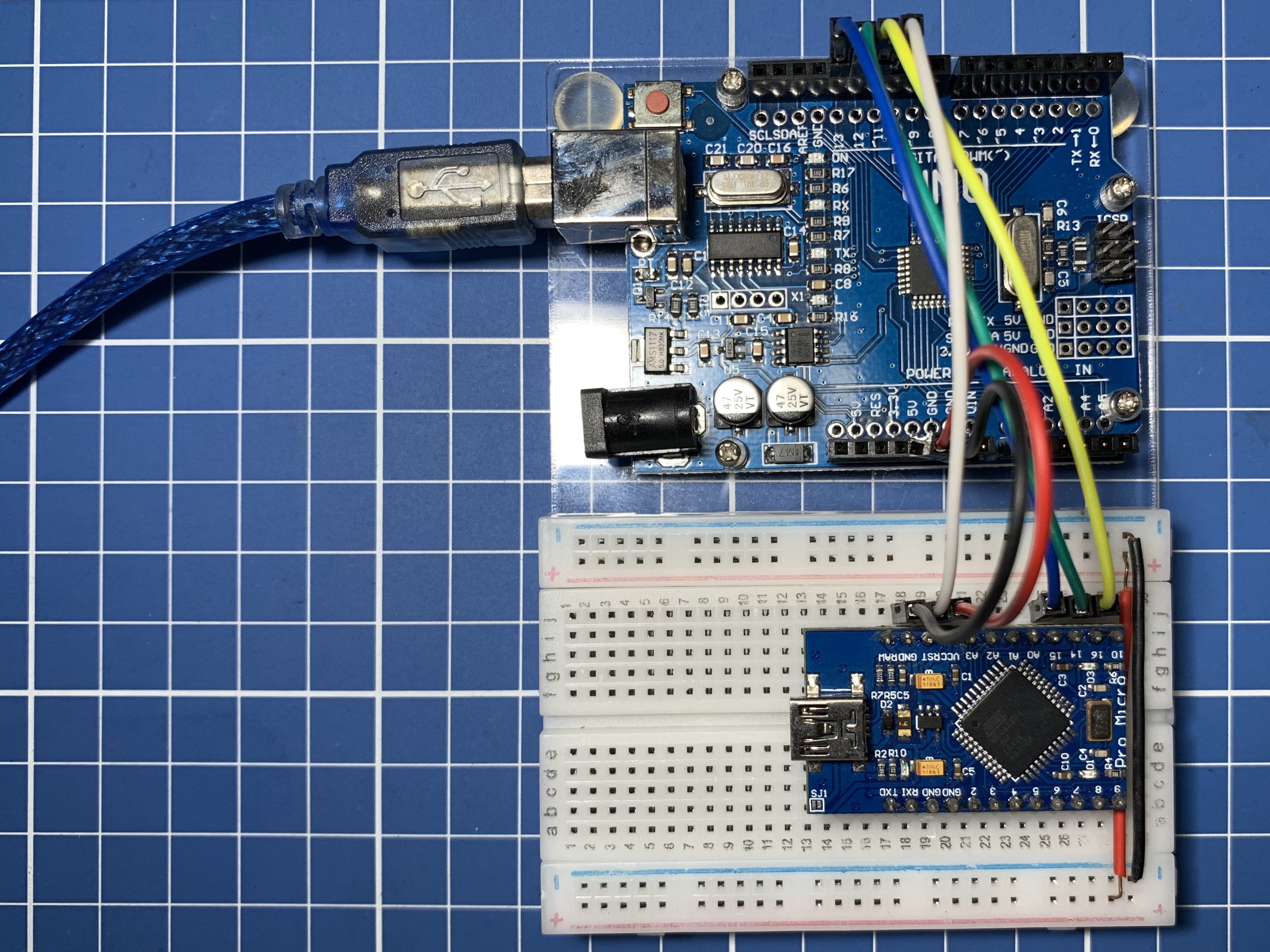
Recently, I was revisiting my electronics components and found my old Arduino Pro Micro clone, which has a similar board with Arduino Leonardo as both boards are based on Atmel Mega32u4 microcontro…
leaden ruin
So you have two arduino boards. Are they the same model?
Which one is connected to your computer?
pine bramble
the uno is connected to the pc
then i have a mini that im doing stuff to through the uno

 last roost
pine bramble
then i have a mini that im doing stuff to through the uno
last roost
pine bramble
then i have a mini that im doing stuff to through the uno
try uploading the code with the pro mini disconnected.
last roost
what are you trying to do with the mini?
pine bramble
make it reconizable as a mini. at the moment its not reconizable because its a knock off
pine bramble
last roost
try uploading the code with the pro mini disconnected.
just did it ended up with the same message
north stream
You may need a CH43x driver for it, depending on which serial chip it has
last roost
ok so you have arduino clone which you want to use as pro mini.
what board config have you selected in tools menu of the ide?
pine bramble
north stream
You may need a CH43x driver for it, depending on which serial chip it has
mega32u4? i think thats the chip name
pine bramble
last roost
ok so you have arduino clone which you want to use as pro mini.
what board confi...
what do you mean?
last roost
pine bramble
mega32u4? i think thats the chip name
on the UNO, there will be the main atmega controller as well as a smaller chip near the usb port
what is written on it?
north stream
Ah, the mega32U4 has its own USB connectivity.
last roost
north stream
Ah, the mega32U4 has its own USB connectivity.
then why does @pine bramble want to discover it as pro mini?
pine bramble
i want to use the mini as a 2 key keyboard in short
north stream
The 32U4 is more like a Pro Micro than a Pro Mini. It should be able to serve nicely as a 2 key keyboard.
 north stream
Ah, that's not on the mini, that's on the Arduino.
pine bramble
yeah @last roost asked for it
last roost
http://www.retrobuiltgames.com/the-build-page/macro-keyboard-v2-0/macro-keyboard-v0-4/
This may help. its using the pro micro (32U4).

 cedar hornet
Hello people! I am trying to use a PCA9685 Servo driver with a Digispark ATTiny 85. I tried the sample code for the Servo Driver but it doesn't work, giving TwoWire class related errors. Does anyone have any idea how to interface the Digispark with the servo driver? Thanks!😅
gilded cargo
north stream
Interesting. There are ways to investigate the EEPROM contents directly, using ...
Back again. 😛 I managed to take a look at it. The EEPROM is indeed functioning as it should. reading and writing byte 0 does retain its value, so there is something going wrong with the code/library.
#include <EEPROM.h>            // Memory control

void setup() {
  Serial.begin(74880);
  while (!Serial) delay(10);
  Serial.setTimeout(250);
  uint8_t MEM_Reboot = 5; // Change to reboot EEPROM.
  Serial.println("MEM_Reboot says " + (String)MEM_Reboot);
  uint8_t MEM_Pulled = EEPROM.read(0);
  Serial.println("Byte 0 says " + (String)MEM_Pulled);
//  if (MEM_Reboot != MEM_Pulled) // Rebooting EEPROM?
//  {
//    Serial.println("Doink");
//    EEPROM.write(0, MEM_Reboot);    // EEPROM Rebooting.
//    // Do some stuff to EEPRPOM
//  }
}

void loop() {
}
Produces 2 different numbers when I change MEM_Reboot before flashing.
#include <EEPROM.h>            // Memory control

void setup() {
  Serial.begin(74880);
  while (!Serial) delay(10);
  Serial.setTimeout(250);
  uint8_t MEM_Reboot = 1; // Change to reboot EEPROM.
  Serial.println("MEM_Reboot says " + (String)MEM_Reboot);
  uint8_t MEM_Pulled = EEPROM.read(0);
  Serial.println("Byte 0 says " + (String)MEM_Pulled);
  if (MEM_Reboot != MEM_Pulled) // Rebooting EEPROM?
  {
    Serial.println("Doink");
    EEPROM.write(0, MEM_Reboot);    // EEPROM Rebooting.
    // Do some stuff to EEPRPOM
  }
}

void loop() {
}
Produces the same numbers without fail, no matter how much I change MEM_Reboot.
gilded cargo
ok, I discovered something weird. Imposing a 1 second delay right before the if-statement makes it work all of a sudden..
so the arduino, or the library, can not handle reading and then writing the same byte of EEPROM in quick succession.
im going to throw this up on the arduino forum, this is a weird one.
gilded cargo
EEPROM read/write strange behavior.
north stream
You've done some solid research there. I know the EEPROM takes a certain amount of time to erase/rewrite, but it would be nice if the library accounted for that, or at least documented the delay.
paper mist
hi guys, working on an intel 8048 dumper pcb. original creator used an arduino uno, i'd like to use a pro micro, but the code was written to use an entire port of pins and not set to a list of individual ones (if that makes any sense). i'm wondering how i'd go about rewriting this to use a list of pins available on the pro micro (original code attached) thanks!
gilded cargo
north stream
You've done some solid research there. I know the EEPROM takes a certain amount...
Somebody has given me a new lead to pull; Apparently turning on serial will cause it to softboot a second time after upload. Which means the eeprom reset cycle has already run its course before it can actually come around to output to serial the second time. What do you think? 
 halcyon grove
Hi all! I just got my Clue in the mail. Does anyone know what the name of the default/example program that's on them when they ship is? I want to start playing around with that to add the other sensors I picked up, but not sure which of the example programs it is. It gives a readout of all the built in sensors. Also, is there any reason why the 3rd magnetometer value is always higher than the other two, no matter which way I orient the Clue?
rough torrent
halcyon grove
Hi all! I just got my Clue in the mail. Does anyone know what the name of the de...
I think it's one of the Adafruit Arcada full board test examples in Arduino
halcyon grove

Thanks, hmm I'm not seeing that in the list but I'll keep looking. This is the program I'm talking about
 solemn cliff
halcyon grove
Thanks, hmm I'm not seeing that in the list but I'll keep looking. This is the ...
solemn cliff
halcyon grove
Thanks, hmm I'm not seeing that in the list but I'll keep looking. This is the ...
did you find it ? is this that ?
https://learn.adafruit.com/adafruit-clue/arduino-test
north stream
@gilded cargo Hmm, that could be. I guess a little code to blink an LED or something would let you know if it had run
 solemn cliff
night portal
What does this code say to you guys?
solemn cliff
night portal
What does this code say to you guys?
to me it says: set the color of the pixel after the last pixel (which doesn't exist) to half brightness white
did you want fill() or did you want the last pixel (which will be numpixels-1 due to the index starting at 0)
night portal
@solemn cliff ahhh I see what you mean. I did want to fill actually. I've been seeing some weird effects using this code. Do you think that error may cause all of the LEDs to turn on full brightness? Because that's what is happening when I plug everything into my circuit
solemn cliff
I don't know but you don't initialize the values of the neopixels in setup(), you probably need to do a clear() before show() there
night portal
hmmm really? I thought I followed what the example codes in the library said, except for the mistake already mentioned
solemn cliff
other than that, I don't know much about it
night portal
okay, thanks for your help! I can't believe I totally missed that
halcyon grove
Thanks yeah it looks like that's it 🙂 I was also able to pull it off of the device. I haven't worked with circuit python before so I had assumed it was an arduino sketch. I'm reading up on that now, the Clue is such a fun device!
pine bramble
Hello Adafruit! I am trying to reproduce an example in Adafruit EPD library. Specifically the ACEP color display example. I am having a hard time, even establishing communication with the display (with horrible waveshare library it works). Is there anywhere I can find the specific hardware setup (boards, pins, connections) you used to produce the video of this display in use with the EPD library?
gilded cargo
north stream
<@!177687782620266496> Hmm, that could be. I guess a little code to blink an LE...
Ive put it to the test by buzzing a pieso, it indeed seems to boot up twice when uploading, even when there is no serial being started. It just always does that. Kinda annoying for my purpose, but not the end of the world.
dreamy minnow
hey guys, i've got a stepper and a pot hooked up. also using accelstepper. the way i do things now is i got a var max steps, then read the pot, and tell the stepper to go pot % of max steps. problems is the stepper sometimes moves fast enough that it get's jittery because the pot reads something (70%) and it immediately sends it to the stepper(driver). Basically if the pot is moving while the stepper is moving it get's jittery, what i thought of doing is having a dummy value which follows the pot at a slower pace
also one mistake i have here is that everything is an int(i think) so no .1

also sorry for picture and mixed language, but i just needed an idea on logic or something
 green heath
You could take an average of several readings
If everything is an int then dummyproc wont work. It needs to be a float
I am not familair with accelstepper but if their functions accept only integers then it wont work either. Your dummy value will just cut of at the decimal
dreamy minnow
an avreage of several readings sounds ok, but i also need the final position of the pot to be the one sent to the stepper
with a max delay of 500 ms
dreamy minnow
btw, generally speaking, is it better to have everything in functions and call them in the loop, or just have everything in the loop?
pine bramble
The loop should be almost empty.
Preferably it's the central interpreter to a state machine, if I have things right.
I treat the main loop as a kind of ISR almost. As bare as possible.
(Interrupt Service Routine)
If setup() never exits (due to encountering a loop) that's fine .. you don't have to use loop() where it doesn't make sense to do it.
north stream
Note that loop does have to exit for the serial service routine to run
 deep raven
Hello, I am new to using adafruit and a semi-noob when it comes to tech. I have purchased and am planning to use an Adafruit Feather HUZZAH ESP8266 for a school project, but am having alot of trouble with the conversion from lux to arduino language. When following the steps on the website under the product, I keep coming up with an "invalid head of packet" error when I try to run the simple test code seen at the bottom of the page. I made sure I followed the steps to the T, but this error keeps reoccurring. Can anyone help me find a solution to this error?
also here is the code


 topaz compass
Never take a picture of an error message that's text.
topaz compass
The error message. Everything in your image is unreadable. Normally I won't even try to read an error message from an image.
deep raven
I will enlargen the photo, so you can zoom in
topaz compass
Don't bother.

 analog lagoon
Hi all... I am setting up an automated garden with a plastic solenoid from Adafruit, and could not get it to activate using a TIP120 transistor with a 2.2k ohm resistor going to the base using digitalWrite set to HIGH. Then, while doing some testing, I used analogWrite set to 255 and it worked. Shouldn't those things be the same?
topaz compass
analog lagoon
Hi all... I am setting up an automated garden with a plastic solenoid from Adafr...

Arduino Stack Exchange
As the title states. What's the difference between the two?
analogWrite(pin,0-255) vs digitalWrite(pin,LOW-HIGH)
analog lagoon
Hey @topaz compass ... I actually just read that thread ha
But the article says analogWrite set to 255 and digitalWrite set to HIGH should produce the same results... but analog worked and digital didn't... any idea why?
topaz compass
It's not clear to me that the two should produce the same results. Because they're different methods, I would expect there to be a functional difference, though the article doesn't seem to say what.
pulsar junco
analogWrite of 255 should just be a 100% duty cycle PWM signal, which physically shouldn't be any different than a hi pin?
like on a scope I would think they would read the same but maybe I'm wrong
deep raven
nevermind, I figured out the board I downloaded was the incorrect version, thank you for all who helped!
analog lagoon
Thanks @pulsar junco ... yeah it's really strange... The code is identical, except for the analogWrite set to 255 works, and digitalWrite set to HIGH does not work.
spiral knot
Hello! I've been playing with the bluefruit multi central and peripheral example codes but they refuse to connect! Does anyone know if I have to anything special to them to get them to work?
fading zenith
I cant get the Adafruit Jewel to work. Does anyone have any experience with it and could help me figure things out?
elder hare
How would i send this over ArduinoJson ?
struct pattern
{
    const String Name;
    const bool Enabled;
};

struct pattern Pattern[] =
{
    {"SOLIDCOLOR",   true},
    {"RAINBOW",      true},
    {"THEATERCHASE", true},
    {"JUGGLE",       true},
    {"RUNNINGLIGHT", true},
    {"CYLON",        true},
    {"MITOSIS",      true},
    {"TWINKLE",      true},
};
Totem-Pole outputs on GPIO pins.
It's perfectly acceptable to set a GPIO pin to HIGH in INPUT mode. ;)
iirc it'll go Hi-Z then.
For some (all?) use cases that effectively takes it off the bus.
north stream
The older Arduino, setting an input to high would activate the internal pull-up resistor.
 gusty mortar
ok so this one is killing me... I'm trying to find a replacement for the AudioZero library because it sucks and it's not maintained. I have an arduino nano 33 iot. Any of the audio libraries for the MKR family should be fine but i CANNOT use I2S at this time so it severely limits my choices. What I can find has crap documentation...
Anyway I'm chasing this possibility, the Native MP3 decoding library from Adafruit. https://learn.adafruit.com/native-mp3-decoding-on-arduino?view=all
Basically I'm getting an error that says its too much beef for my nano 33 iot. What can I do to get this to fit? Or is there another way? Please advise, I'm desperate here.
../../arm-none-eabi/bin/ld.exe: region 'RAM' overflowed by 12724 bytes

Adafruit Learning System
play MP3 files with only your microcontroller
pine bramble
hello! can someone help me with a code?
i want to detect earthquake using adxl345 and fire by using flame sensor.
when they detect = true, they call the function buzzer to turn on the buzzer.
but, i cant seem to find a way to have both triggered at the same time (earthquake == flame == true)
btw, i am using this for the function
`void buzzerTrig(int delayVar, String triggeredSensor) {
display.clear();
display.setTextAlignment(TEXT_ALIGN_CENTER);
display.drawString(64, 20, String(triggeredSensor));
display.display();
for (i = 0; i < 40; i++) {
digitalWrite(buzzer, !digitalRead(buzzer));
delay(delayVar);
}
}
void loop() {
flameDetection();
accelerometer();
}`
pine bramble
i used millis to blink the buzzer
`void buzzerTrig() {
const long currentMillis = millis();
Serial.print(currentMillis);
Serial.print(previousMillis);
Serial.println("----------------------------------------------xx");
if (currentMillis - previousMillis >= interval) {
    previousMillis = currentMillis;
    if (buzzerState == LOW) {
        buzzerState = HIGH;
    } else {
        buzzerState = LOW;
    }
    digitalWrite(buzzer, buzzerState);
}
}`
but this only turns on the buzzer at a constant high state;
 lone ferry
What is interval?
pine bramble
lone ferry
What is interval?
i set at 5000 ms
elder hare
in the socket part of my arduino code i have this
    if (inData["brightness"])
    {
        if (_isAllStripsSelected == true)
        {
            for (int i = 1; i < 9; i++)
            {
                Strips[i]->GeneralSettings.Brightness = inData["brightness"];
            }
        }
        else
        {
            Strips[_selectedStrip]->GeneralSettings.Brightness = inData["brightness"];
        }
    }
i do this for everything from Brightness Delay Color and so on but i want to simplefy this with a function but how can i do it?
        static void FetchData(char *Name, StripSettings *Strips[])
        {

        }
i want to be able to just call
FetchData("Brightness", Strips[]->GeneralSettings.Brightness)
when I serial print
its just like this
NO FIRE.
8231276250----------------------------------------------xx
NO FIRE.
NO EARTHQUKE.
NO FIRE.
NO EARTHQUKE.
NO FIRE.
green heath
are there any good serial monitors? I am not using the arduino platform. the one I am using right now displays either hex or ascii
lone ferry
@pine bramble It's not obvious what your previous millis and current millis are (use println instead of print) but it looks like 82312 vs 76250, so that indeed is 5000ms later. Your buzzerTrig function appears to work correctly.
pine bramble
lone ferry
<@456226577798135808> It's not obvious what your previous millis and current mil...
but the problem is it stays HIGH unless I trigger the accelerometer again to call the buzzer function
lone ferry
You need to call it again to turn it off.
pine bramble
also, i wanted it to have a blinking effect? (on then off) but I have no idea how to use it other than using delays
lone ferry
@green heath what OS?
green heath
@lone ferry windows
lone ferry
I've used CoolTerm before, which is pretty decent. It looks like it also works on Windows.
gusty mortar
disregard my post above, I have finally, after some arduous library modifications found a great quality and working combination of code and hardware to get reliable WAV playback on the Nano 33 IoT.
If anyone is interested when i finish tayloring my library i'll post my solution here
green heath
I am unable to upload to my arduino nano due to the old bootloader.
flashed in a new one using arduinoISP and the IDE uploads perfectly fine.
but using avrdude programmers just keeps hanging
I am trying to get the actual error message but the bat files dont stay open
green heath
''avrdude: stk500_getsync(): not in sync: resp=0x00'' aha
ah solved it by increasing the baud
 shadow zenith
Could anyone help me with a bootloader problem I'm having with a feather 328p?
north stream
Are you having trouble installing a bootloader, or using one?
deep raven
Hello, me and a partner are currently trying to upload a simple code onto our ESP32 huzzah32 feather board. The code is to make one of the LEDs on our feather board light up. We have spent a large amount of time configuring the settings on arduino for our board, downloading libraries, etc. But to no avail, the LED on our feather board is still dark. Is there an issue with our code to make the LED blink, and if there isn't, what would the external issue be.
edit: it is compiling and uploading to the board, while asking for the RTS pin, to which we press the button labeled reset, but is still not working
code:
void setup() {
pinMode(13, OUTPUT);
}
void loop() {
digitalWrite(13, HIGH);
delay(5000);
digitalWrite(13, LOW);
delay(5000);
}
shadow zenith
Sorry, was AFK
I had a working device and the bootloader stopped working. It just hangs when I try to upload a new program. It's still running the last program though. I'm getting 10 messages that say: avrdude: stk500_recv(): programmer is not responding
avrdude: stk500_getsync() attempt 10 of 10: not in sync: resp=0xfa
deep raven
ignore my issue, my partner has figured out the solution
thank you for all of those who read it
 cerulean verge
Good day to you guys.
I am graduating in digital composition in masters degree in a month. I'm also a steel tongue drum maker and my goal is to create a sequencer driven steel drum machine. So I'm using arduino leonardo with mosfet and solenoids.
I'm incredibly basic and noobish in electricity and powering things up. Here's my first issue that i've encountered and can't get my head around it:
So here's the scheme, which looks pretty simle to me:

And here's how the same scheme looks in reality (I'm following some engineers tutorial)

Now, you can see that he uses powerbirck which is connected to nowhere. I don't see that it would go to 220V. I see that he cut the fat wire and took + - and hooked it with GND and VIN of mosfet module.
And here's where I loose track of things.
-
I have a simple powerbrick 12V, 5A. Can I simply cut the wire that is meant to be plugged in and connect its + and - with GND and VIN? Will that be the same as in this guys scheme?
-
Why there's a brown wire going from arduino to nowhere? (See the connector above on the right next to the power bircks cables).
Here's the power that I have:

Sorry if this is reletively simple question. I went to two electronic shops and none of those guys could answer me what's going on in this guys scheme lool.
cerulean verge
Maybe the biggest question is won't it fireup my house? I figured out that the black block attached on the wooden board is lipo battery. And I'm using a 12V 5A, solenoids are 12V 300mA
lone ferry
Do you have a link to this tutorial, @cerulean verge ?
As for your first question, yes you can cut off the plug and directly use the wires. However, you'll want to use a multimeter to test which lead is +12V and which is GND.
That brown wire is probably simply not used but attached to the connector so it's out of the way. Not entirely sure what these three wire colors mean. (Brown, blue, yellow/green are usually found on mains wires but that's not something you'd connect to your Arduino.)
cerulean verge
@lone ferry Oh, thank you for responding to my call for help.
Here's the link: https://efundies.com/midi-controlled-solenoids-with-arduino-and-ableton-live-part-1/

In this 3 part article we teach you how to control electronic solenoids from Ableton Live, by using some Arduino programming, a little bit of MIDI knowledge, and some basic electronics. At the end of the series you will have a setup that is capable doing this. This is a pretty complex topic so it is split into 3 parts [...]
I have cut off the wire and I got red and black wire.
So I asume black is ground and red is the positive one?

This is what I already have.
lone ferry
You can assume it but I would measure it.
If you don't have a multimeter there are other ways to figure out which is + and which is GND, but a multimeter is easiest.
cerulean verge
Ah, I only have contactless sensor which yu can see in the picture
It shows if current is flowing in the wire. But it beeps if I put it close to both wires, so I guess it's not what I need.
And if I conenct things the wrong way, everything will burn yes?:D
What other ways you're refering to?
lone ferry
If you have an LED and a large resistor, connect those between the two wires (in series). If the LED doesn't light up, flip it around. This tells you which way the current flows.
cerulean verge
Can I do it simply with a lightbulb and two wires?
Don't have a LED and large resistor.
Hm or maybe I can simply test it on solenoid?
lone ferry
The reason for using an LED is that it only lets current through in one direction, that's not true for a lightbulb.
cerulean verge
I see.
So would it make the chain on fire or it would simple not work?
I mean if I asume the red is 12v and simply join it all together
lone ferry
Usually electronics don't like it if you put the voltage the wrong way around. It depends on the max ratings of the components whether stuff will go up in smoke or not. But something like an Arduino will probably stop working really quickly.
cerulean verge
ah, okay
I will go buy the multimeter. So after hooking it up, I should see if the current is coming or not, right?
For example. I join red with red, black with black and there's no current. It means that the red is GND then, right?
lone ferry
No, you'd measure voltage. If red-with-red and black-with-black says 12, you're good. If it says -12, then red is really GND and black is really +12.
lone ferry
Having a multimeter is a good thing when you're doing electronics 🙂
cerulean verge
Okay 🙂 Going to buy one now.
It's my first encounter with this magical source of energy.
cerulean verge
Hello guys,
I have managed to hook up everything and it seems to be working perfect through ableton and arturia sequencer.
But. When I check the voltage when solenoid is active - it warries between 5 to 9 and if I put my hand next to, it has a very weak hit.
Is this to be expected from 12v solenoid? I mean how will it move a stick if it even stops when I gently add my finger to it. I've checked voltage in the chain, everything is at 12.33V, so seems legit. I have set midi note velocity to 127.
cerulean verge
Ah, maybe it's just 12v. Could anyone please tell me if I can add up to 22¬ solenoids to arduino leonardo? I am using 6 solenoids now on PWM digital section and there's only 13 numbers, so can I use analog tab and SCL SDA AREE GND slots for solenoid driving?
rough torrent
GND is just, ground you can't use that
AREF is the analog reference voltage, you can't use that
SCL and SDA is basically just A4 and A5 (maybe in that order) duplicated so the I2C pins are in a consistent spot
But you can use the analog pins like digital pins
cerulean verge
Ok, is there anotherway I could expand it?
This is my current setup which works pretty well.
@rough torrent I am thinking to shift from 12v solenoids to 24V. Would that mean I only need to change the powerbrick from 12V to 24V? Because my mosfet (transistor is capable of handlig 5A, and 24V solenoids are 2A max).
rough torrent
cerulean verge
Ok, is there anotherway I could expand it?
I would just use a Arduino Mega or a Grand Central because it's easier than driving shift registers or communicating with another Arduino.
cerulean verge
Ah, okay. Will my code work on Mega the same as on Leonardo?
rough torrent
cerulean verge
Ah, okay. Will my code work on Mega the same as on Leonardo?
It should, but maybe some libraries may not - if you are just controlling digital pins then everything is the same, but you get those extra pins to control on the end of the board.
But most libraries are designed to work across all boards
cerulean verge
Ah, okay. I shall check Mega then
rough torrent
cerulean verge
This is my current setup which works pretty well.
<@!633764848924229635> I am t...
Make sure you MOSFETS can handle 24v too! (But I'm more of a software guy then a hardware guy so don't hold me to my word lol)
cerulean verge
Output load voltage :0-24V;
Thank you for your help! And here's what I've found about the mosfet. I believe it can handle 24V then.
elder hare
having problems with platformIO
everytime i open serial monitor i get this
Pastebin
Pastebin.com is the number one paste tool since 2002. Pastebin is a website where you can store text online for a set period of time.
 normal sedge
Hello guys, hope ur doing good!
Does it happen that anyone knows the circuit name which expands i/o pins in Arduino?
pine bramble
'port expander' is usual
green heath
Shift register?
opaque matrix
@normal sedge take a look at the mcp23008 and mcp23017. You can connect multiple of them over i2c to get as many io pins you need.
pulsar junco
General rule is to post your problem/question so everyone has a chance to answer
 gloomy sandal
ah ok
As a microcontroller I do not use an Arduino but an ESP8266, which is programmed like an Arduino with the Arduino IDE, so it is just a different hardware.
Setup: an ADXL345 (accelerometer) is connected to the ESP via the I²C bus, in the code the tilt of the ADXL345 is measured and displayed in the serial plotter/monitor. Because I am only interested in the X-value, I have commented out the display of the other values. The code is a shortened variant, I have deleted everything unnecessary.
Function: I want the ADXL345 to be tilted less than 5,3 (no degrees, it is a different system and 5,3 are about 45 degrees). For this I have queried if
event.acceleration.x < 5,3 then the led should shine. I took event.acceleration.x, because in the Serial.print(event.acceleration.x); and thereforit must be a variable. But it didn't matter how big or small event.acceleration.x was, the led always lit up. Then I checked the pin with a simple blink sketch and everything works as it should. So I thought that maybe it is because of the variable event.acceleration.x. So I inserted a float "a" and assigned it with a = (event.acceleration.x) so that the value is really a variable. To check that event.acceleration.x is assigned correctly I use Serial.println(a) to display a and everything works as it should. In the serial plotter there are also no bursts of the value, which could introduce errors. Now that I am sure that "a" is 100% a variable and a corresponds to event.acceleration.x, I did the same with the led again and it still doesn't work. I don't know what to do
should i send the code?
pine bramble
replace '=' with '==' in a test for equality
gloomy sandal
still doesnt work
pine bramble
get a reliable Serial.println() to simulate LED states.
gloomy sandal
if((a) <= 5,3)
{
//digitalWrite(D3, HIGH);
Serial.println("AAAAAAAAAAAAAAAAAAAAAAAAAAAAAAAAAAAAAAAAAAAAAAAAAAAAAAAAAAAAAAAA");
} else
{
//digitalWrite(D3, LOW);
Serial.println("CCCCCCCCCCCCCCCCCCCCCCCCCCCCCCCCCCCCCCCCCCCCCCCCCCCCCCCCCCCC");
}
i coded that to simulate the led but still the same result
pine bramble
what does '5,3' mean?
gloomy sandal
the value that is output is in decimal and 5.3 is the value that is output when the ADXL345 has the slope that I want.
this is not adjustable and anchored in the libraries
pine bramble
Why use a comma
To me that's a tuple of elements '5' and '3'
It seems pretty clear a conditional test you have constructed isn't obeying the rules you think it is.
gloomy sandal
omg yes the comma was the problem. when i use . instead of , it works like i should. you are right thank you so much 🙏
pine bramble
;)
It's okay that's great -- less work for both of us. ;)
I have seen other countries using the comma notation rather than the American/elsewhere 'decimal point' dot glyph.
gloomy sandal
yea in germany we use the ,
pine bramble
Thanks - that explains a lot.
gloomy sandal
an that sometimes causes coding problems
pine bramble
The comma is a better choice visually, but of course it won't be recognized in some coding contexts.
The most prolific body of C language code I've seen that wasn't written in English-derived code was .. in Polish!
It'd be a significant contest between German and Polish for the leader. ;)
Oh yeah in French, too.
gloomy sandal
i think my problem is that i "know" several programminglanguages and some of them accept , and some don't and sometimes they get mixed up in my head.
pine bramble
I'm in the vast minority in that I use the C Preprocessor to essentially change the way code looks. ;)
This is how that's done with a lot more skill and knowledge than I have:
 odd merlin
hi lol
im dumb
I just started using arduino, after like, a really long time.
And you see... I lost my prior computer
and that had the libraries on it
idek how to find these files

google is dumb and is not helpful
so like- yehh...
ye so, idek what adafruit is
but like, turns out whoever setup the libaries
is actually smart
and put it on the arduino libary thing
this makes my life so easier now
thanks
nvm lol
 pine bramble
TFT and Touch are suggestive of a display with a touch screen sensor thing.
Often easier to get out the magnifying glass and read the numbers off the chips.
One of them may be directly referenced in the relevant software driver(s) code base.
 fair acorn
Anyone have experience using visual studio? I'm having a problem with multiple definitions in C++ that I just can't seem to solve
 icy raft
Hey guys, I am having some issues with the adafruit itsybitsy and the nrf24 module. I used the nrf 24 module on arduino before and just transferred the code over, but I am not able to get connection in between the two nrf24 modules anymore. I connected the SPI from the rf24 module to MISO MOSI and SCK, and CE to 9 and CSN to 10 on the itsybitsy. I have a 10Uf capacitor on both radios as suggested from the nrf24 manual to make them work as well. I also attatched the code I used on the itsy bitsy. I have the other nrf24 on an arduino mega and its telling me that there is data being sent.

 young flint
I'm not sure how to word this, but is there a way to send a variable to a function and be able to change that variable inside that function?
Like if I had
int x = 1;
test(x);
...
void test(int i)
{
//change the value of x here
}
oh wait i can just do a return value
rough torrent
Search up references too in C, you can provided a pointer to as many variables as you want as parameters to the function and you can modify them appropriately without having to return anything 🙂
green heath
i learned pointers by making a mindmap. Its incredibly effective way to see what the different syntaxes mean. Its been stuck in my mind for almost half a year now and I can still reproduce it.
The only thing that has eluded me so far are structure pointers and double pointers
 bleak socket
Hellooo
got a small question, maybe its just logic but yeah,
I just measured the voltage of my doorbell, it gives 2.2v when its not pressed, but when its ringing its 1.8v
Do i need to do any special stuff before connecting it to my nodemcu digital pin? (i looked it up and they can handle 3.3v?)
or can i just in the code analogread it and check if the value is below 2 then send me a notification
 pale flame
What door bell are you talking about?
Most doorbells run from about 18 V AC, and would destroy most CPUs
bleak socket
its just a normal doorbell, a really really old one, not even a special one like Ring haha
pale flame
I think you need to switch your meter to measure AC Volts, and measure again.
bleak socket
it was haha
it was on 20 ACV
and on 20 ACV it showed me 2.20v
wait
i might go wrong here

i had it on the top left one, V 20
stuck coral
The line with three dots to the left is the symbol for DC, the ~ in the right is AC
bleak socket
hmm right right so i should put it on 200 then
bleak socket
i meant he 200 V~
well still weird that the 20VDC reads out a number aswel haha
im just trying to stickup the signal to my nodemcu so i can sent a signal when someone is at the door
the switch i think
stuck coral
The solution will most likely be a relay
bleak socket
hmm thats actually a good option
if i can find the right wires, i might also power my nodemcu by the same bell, with a voltage divider if it isnt too much of volt
stuck coral
Its AC not DC, you need to rectify it first, and its a bad idea to use a voltage divider for regulation, use a regulator
bleak socket
hmm :/
thought this would be easy haha 😛
Just plug in the bell in your nodemcu and go
stuck coral
Well, its just not how door bells work.
bleak socket
haha i always thought they did
stuck coral
And its pretty easy, just needs a few extra parts
bleak socket
as in just sent a short signal to a box and make the dingles 😛
stuck coral
It does, but in your walls is AC not DC
bleak socket
oh but im not sure if the cables are directly in the walls
i think these cables come out of the box of the door bell
stuck coral
Doesnt matter, the bell is a AC device, we use AC with longer wires, and it matches with your house wiring which is also AC
Hence why you need a big power brick to charge your phone, its not just turning the socket to USB, its rectifying AC to DC, regulating voltage, regulating current, etc
bleak socket
well i get that, but theres a box at the doorbell, and out that comes a cable to the power socket, and on the other side of the box comes small wiring that goes to the actual doorbell (the push button outside is what i have been talking about all the time haha)
and that small wire to the ACTUAL push button is what i read out with the meter
stuck coral
Yep, there is always a box for the doorbell, its what houses the actual bell. Maybe your unit is special, but also you need to measure between the switch and neutral/gnd if ac, not between the two terminals of the switch.
Well, no matter what, lol
bleak socket
alright will do that, gotta see how the wires go, theres alot of stuff around there 😂
thanks for the help 😄
 wind isle
Hey all! I'm wondering if there's a handy chart that can tell you which numbers code to which color neopixels? I specifically want yellow/orange fade but I'm having a hard time getting the right color. Thanks!
stuck coral
wind isle
Hey all! I'm wondering if there's a handy chart that can tell you which numbers ...
Does this help you? https://www.colorspire.com/rgb-color-wheel/
wind isle
I think so yes! Thank you!

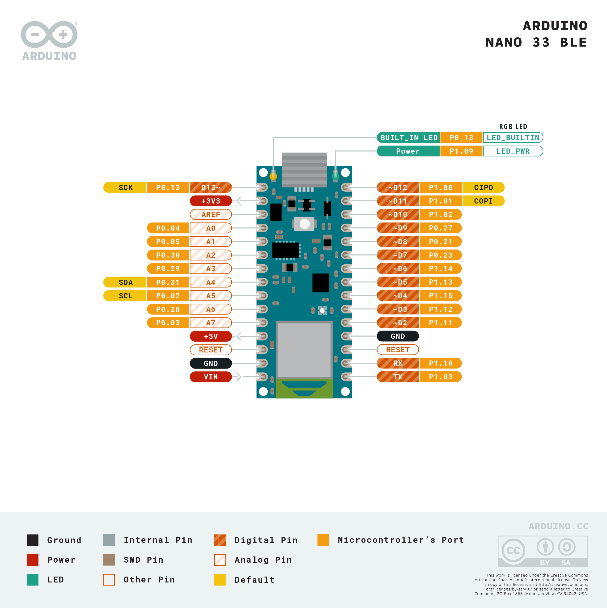


 warm turret
Hi everyone, thanks in advance for help!
I bought a feather sense to use for a home made trackball project. The issue that I'm running into is that anytime the code contains Bluefruit.begin(); it causes the board to crash. I've tried using the example code from here:
https://github.com/adafruit/Adafruit_nRF52_Arduino/blob/master/libraries/Bluefruit52Lib/examples/Peripheral/hid_mouse/hid_mouse.ino
without any success.
I know the board is crashing because the serial console doesn't print output on the serial like it's supposed to. As soon as I remove the Bluefruit.begin(); line and reupload the board becomes responsive again and the serial console prints out again
When the board crashes it usually becomes unrecognized and I have to put it in bootloader mode to make any changes. I have tried this using multiple computers all with the same results.
Could this be a bad board?
GitHub
Adafruit code for the Nordic nRF52 BLE SoC on Arduino - adafruit/Adafruit_nRF52_Arduino
 molten maple
@bleak socket Perhaps you could change the doorbell button to a 2-pole Pushbutton (such as DPDT). Use one pole N/O contact for the existing Doorbell circuit, and the other N/O contact for your microcontroller input
bleak socket
Hmmm that's new I could look up to do that, imean, the signal wire is.already split
So that won't be an issue
It's just the moment of me being weird about the volts,
2.2 when not pushed in and 1.8 when pushed in
And digital read can only handle 0-1 haha
Well reads 0 to 1, but idk how to get 2.2 volts down to 0 and when pushed the 1.8 is high
molten maple
yea having a separate dry contact on two pole pushbutton means you don't have to worry about the existing circuit and voltages. it is what i would do in your situation instead of doing some weird signal conditioning or whatever
elder hare
i can't see the problem so i need extra eyes
void StripSettings::Rainbow()
{
    for (uint16_t i = 0; i < _NumLeds; i++)
    {
        _Leds.data()[i] = CHSV(Color.RainbowHue + (i * 255 / _NumLeds) + GeneralSettings.Position, 240, GeneralSettings.Brightness);
    }
}
so when GeneralSettings.Position hits 32 (length of strip) it resets to 0 and repeats! this works for all patterns but not the rainbow pattern.... i see the red color at the tip fading away and yellow following and then suddenly it resets to 0 hmmm
 glacial spire
Try out putting the general settings to the serial monitor so you can find if there is an actual issue with your code. If it shows up like it should. Consider trying another power supply. These simple steps helped me a lot while I was troubleshooting with the strips.
 stone spade
Does anyone know how to send the HID codes for the 2 additional side buttons for a 5-button mouse (on a Mac)? Either in arduino or CircuitPython?
warm turret
has anyone had issues with Bluefruit.begin() causing the board to become unresponsive?
 glass hound
Hello everyone! i would like help with making a safe but very powerful electromagnet
also are there any good free Arduino simulators?? i have found a few but never got any to work.. maybe i just need a tutorial??
cedar mountain
glass hound
Hello everyone! i would like help with making a safe but very powerful electroma...
How powerful is very powerful? 😅
glass hound
will its about size kinda
i want it to be 5 mm in diameter but able to pick up as close to 1 lb?
cedar mountain
Gotcha. You never know what people are going to want to try. The answer could have been "Not too powerful... I only need to lift a pickup truck with a crane..."
 icy moss
Anybody knows how to wire and program an 8x8 matrix? i got the one with 16 pins, and it cant seem to find any help online
glass hound
what is the matrix for
odd fjord
@icy moss can you provide a link to the Matrix you are using?
Is it this one? https://www.adafruit.com/product/455 there is a link to a tutorial there.
elder hare
i can't see the problem so i need extra eyes
void StripSettings::Rainbow()
{
    for (uint16_t i = 0; i < _NumLeds; i++)
    {
        _Leds.data()[i] = CHSV(Color.RainbowHue + (i * 255 / _NumLeds) + GeneralSettings.Position, 240, GeneralSettings.Brightness);
    }
}
so when GeneralSettings.Position hits 32 (length of strip) it resets to 0 and repeats! this works for all patterns but not the rainbow pattern.... i see the red color at the tip fading away and yellow following and then suddenly it the pattern resets (jumps/lag)
(just FIY yes GeneralSettings.Position is supposed to count to strip length and then go to 0 and repeat)
elder hare
i can't get the rainbow to cycle 1 turn :/
 limpid ether
why did adafruit stop carrying almost all oem arduino boards? did it just not make sense to carry both those and the Metros?
pine bramble
@glass hound Adafruit put in more than one electromagnet in their catalog not all that long ago.
The rare earth magnet pulls I have (from old 5" hard disks) are quite strong.
(Permanent of course).
They seem to get a lot of extra strength from the plates they are on, but I haven't tested how that works.
Some I thought were glued on but seem to simply be 'stuck' by the magnetism.
I have no idea how anything but a coil of wire (and a core of some kind) forms a strong electromagnet efficiently.
The strength of the magnetic field of an electromagnet increases when:
(a) The current is increased
(b) The number of turns is increased
(c) The turns of wire are pushed closer together so that the length of the solenoid becomes shorter
(d) A soft iron core is placed into the solenoid
I think you can count on 'increased current' in most scenarios for a stronger-than-before electromagnet.
The other factors would (then) be used to reduce that current for a given field effect.
That'd be my guess from high school physics (and such) and 'field effect' is my placeholder term for the desired increased property. ;)
25 kg holding force:
https://www.adafruit.com/product/3875
(that's twenty bux .. why don't I have one of these, yet?)
Divide the holding force by 5-10 to get a rough estimate of how heavy a thing it can pick up.
 raven sandal
Is it intentional that issue reporting is disabled on this repo?
https://github.com/adafruit/WiFiNINA
GitHub
Contribute to adafruit/WiFiNINA development by creating an account on GitHub.
 formal crypt
does anyone want to put together a shopping list for me? Ive never built an arduino before and I want to make a data logger with gps, 3 accelerometers, 5 potentiometers. Im a programmer so Im not worried so much about the software side, but the hardware side is making my eyes glaze over.
Im building a motorcycle race data logger so i need an arduino or something that's fast and can handle all the sensors.
And Im going to need a starter kit because I dont know exactly what I'll need and i hopefully wont need to run out and buy more stuff.
Or if anyone knows of a book i should read that would embue me with the power to look at the adafruit parts catalog and know what I need, please let me know.
pine bramble
@formal crypt Budgets get way out of control, fast.
There's a wishlist mechanism on adafruit.com
I usually put my greed list in the shopping cart, and convert that to a new wishlist, and then empty all but five items (say) from the shopping cart.
Sooner or later I hit my price point.
'all the sensors' is probably the bottleneck.
I'd get them all and the target and any hardware needed to interconnect them.
Get them 'all' working (if you can).
That'll buy a lot of time to decide on anything else needed.
Top down, bottom up, middle out
limpid ether
formal crypt
does anyone want to put together a shopping list for me? Ive never built an ardu...
how are these physically laid out?
glass hound
pine bramble
<@!128409457792253952> Adafruit put in more than one electromagnet in their cata...
What does that mean
limpid ether
like, do you want all the knobs to be next to each other on a kind of control panel, or do you want each one connected via wires?
if the latter that'll be a bit more expensive/annoying
assuming the former: https://www.adafruit.com/wishlists/522504
Adafruit Industries, Unique & fun DIY electronics and kits : My Wishlist - Tools Gift Certificates Arduino Cables Sensors LEDs Books Breakout Boards Power EL Wire/Tape/Panel Components & Parts LCDs & Displays Wearables Prototyping Raspberry Pi Wireless Young Engineers 3D printing NeoPixels Kits & Projects Robotics & CNC Accessories Cosplay/Costu...
if it's the latter swap the 3 breadboard potentiometers for 5 of https://www.adafruit.com/product/4493
For the easiest way possible to measure twists, turn to this STEMMA potentiometer breakout (ha!). This plug-n-play pot comes with a JST-PH 2mm connector and a matching JST PH 3-Pin to ...
you'll need to solder header to the microsd board but it's really easy
you'll need the tools obv
adafruit has some pretty high-quality ones but for a one-off small thing like this you'll be fine with a ~$10 kit off your favorite ecommerce site, here's one (not necessarily an endorsement) https://www.amazon.com/Soldering-Kit-Temperature-Desoldering-Electronics/dp/B07XKZVG8Z
if you don't get that one make sure you get a soldering iron and solder suitable for electronics work, a stand and solder sucker will be nice to have too
@formal crypt
limpid ether
awful diagram to explain how those would fit together
 pine bramble
@glass hound It means they sell electromagnets. ;)
glass hound
I'm looking to make my own
formal crypt
limpid ether
awful diagram to explain how those would fit together
@limpid ether this is amazing. thank you.
 still raven
hi, i hope this is the right channel. my school had an addressable led strip in the makers lab, and i'm trying to program it. problem is, i don't know the type of controller it uses. is there a way to determine what type of controller it uses? so far i've tried the common ones with FastLED and nothing seems to work/
pine bramble
@still raven APA102 is the DotStar type. Most of the others are the NeoPixel type, or else aren't addressable.
The APA102 can be bit-banged easily enough; the NeoPixel type is a lot harder to bit-bang.
 pliant totem
Guys, im having trouble with my SPI SD Card reader-writer module when working it with arduino
so i've programmed my arduino to write text files to an sd card at a given interval. It used to work but now it somehow doesn't
Im currently using an SD-Fat library from github

GitHub
Arduino FAT16/FAT32 exFAT Library. Contribute to greiman/SdFat development by creating an account on GitHub.
and an SPI library
does anyone have the same problem or does anyone have any insights?
 light basin
Is there a way to have the arduino ide ignore a function call. I have a program that compiles for esp32 or esp8266. 1 function does not exist in the esp8266 library but does for esp32.
 woven mica
light basin
Is there a way to have the arduino ide ignore a function call. I have a program...
woven mica
light basin
Is there a way to have the arduino ide ignore a function call. I have a program...
use #ifdef
light basin
Thanks, i didn't figure you could use that in the code section. I had it #ifdef used for the library includes up top
 lunar zodiac
anyone can help me with a working guide for controlling leds? I am using a NodeMCU to control 6 leds per panel for a nanoleaf replica, but i am unable to change my LED colours.. tired WLED and Moodlite, but cant find a correct recent guide
 hollow condor
Hey guys, anyone online? Need some help
leaden walrus
best to just ask. and be patient. lots of people online, but may not get an instant response.
rough torrent
(this place is more like a forum when you first ask a question but then once the response comes in then you can experience discord's speed)
 shadow marlin
we would have helped you as we dropped in... put that question out there
 desert spindle
**TGIF!!!!! Trying to connect an RPI to the ItsyBitsy M0 (M4) Express.
The M0 is setup for Arduino-C.
**I can compile c and run it from the COM3 direct command line.
The UART test does not work, example: echo "eyes.blink" > ttyS0
I can get to the Arduino COM3 command line, which is from the direct cable into this adafruit chip. And I can execute the code.
However, when I send the RPI an ECHO, I see nothing here, from the echo.
Any thoughts on how to connect this chip to the RPI? I want to run python scripts on the RPI, to execute compiled C on the chip. I appreciate any suggestions.
bleak socket
hey guys,
i got a weird issue hehe,
i made a PCB in 2018 to simulate keypresses, they are just some simple MX switches connected to the digital read pins on an Arduino Micro
now, im rewriting my code using Keyboard.h
The weird thing is.... when my board is laying on the table, nothing happens in the serial monitor. But when i pickup the board and move it in special ways, without pressing keys on the board, it prints to my serial monitor ????
this is what i have atm
Pastebin
Pastebin.com is the number one paste tool since 2002. Pastebin is a website where you can store text online for a set period of time.
but it prints either K2 or K4
rough torrent
That usually means an intermittent connection - try re-soldering/re-connecting wires
bleak socket
that'd be a bit weird when the board always functioned fine, maybe a key is broken
welp i guess its not the broken key, as all my keys randomly start printing now
pine bramble
@light basin Sometimes I've resorted to adding a blank version of a function definition, especially if the new platform doesn't want/use it (or in a way that needs to function correctly).
Othertimes it's just a well-placed #define x y somewhere in the source tree.
Always consider:
- issues filed in the repository - they can change over time
- turning on all compiler warnings, and fixing at least some of them.
Major compiler updates (They happen but are rare) can break code or simply expose more warnings.
(I didn't see the #ifdefsuggestion - nice idea, also)
molten maple
@bleak socket it sounds like your wiring has floating inputs which can lead to the microcontroller erroneously detecting key presses. Try looking up how to wire input contacts to microcontrollers with pull up resistor or pull down resistor as appropriate.
bleak socket
im still weird why this suddenly happened haha
its on a PCB aswel 
also i keep thinking its my code, because with the old code this didnt happen, but i just overwrote it with new code,
thing is, my old code was from 2018 and i dont have it anymore 🙃
pine bramble
Sometimes I'll pack a $5 USB thumb drive inside a project so I'll have its source code years down the road. ;)
green thunder
pine bramble
Sometimes I'll pack a $5 USB thumb drive inside a project so I'll have its sourc...
I love this idea 😮
rough torrent
You could probably obtain uSD cards for cheaper too and they are smaller but dang that's a big brain idea
pine bramble
;)
It's amazing how much your own code can look to you like you had no role at all in its creation.
young flint
is 1k considered too small for a pull down resistor? i always see example schematics with 10k resistors
 stable forge
young flint
is 1k considered too small for a pull down resistor? i always see example schema...
stable forge
young flint
is 1k considered too small for a pull down resistor? i always see example schema...
is this for I2C or just for a button or similar> The main thing is that it will draw more current, and is probably overkill for the situation. (Do Ohm's law on the voltage and the resistance.) But if it's what you have on hand, it should work.
quartz furnace
Happy Ardunio Day (3/27) everyone 😀
 sweet hedge
hey guys i need some thoughts on this on using nfc on ur phone to tag in and out of place which records their basic data such as name, time in and out,etc. Is this possible ?
cedar mountain
Yep, that's a good use case for NFC.
shadow tusk
Keeps making me wonder why we still can't use phone NFC with security (unlock) for security access, like for buildings with access badges. Seems like it'd be great for that, since people forget badges, but not phones. And a badge alone is 1 factor, whereas if you have to unlock the phone, like when you used Google/Apple/Samsung Pay, you have 2 factors - so theft is "more difficult"