#help-with-projects
1 messages · Page 2 of 1
 earnest grail
And I have some 530 units in the field
I can update the firmware through OTA, and can change DRV chip parameters, so I’m just thinking what I can do for units in the field
 white marsh
earnest grail
And I have some 530 units in the field
white marsh
earnest grail
And I have some 530 units in the field
Gads! I thought this was a one off thing for yourself. Not a ton of them out there.
earnest grail
But it’s kind of a stab in the dark.
Yeah a few units already sold
I had about 5 coming back due to this
And that’s a bit too much for my liking…
All from the first couple of months serial numbers
white marsh
earnest grail
All from the first couple of months serial numbers
Have you tried contacting TI and asking to speak to an application engineer? And also inquire if there are know issues with you date codes?
earnest grail
That’s a good point. I think I’ll do that!
For the next batch I’m changing to the CSD88537
Which is just a tad slower (twice the Qg) and more current capable (and avalanche capable)
Will run the same firmware, with a resistor encoding for the changed mosfet - so I can run it with a tad higher source/sink
white marsh
earnest grail
That’s a good point. I think I’ll do that!
Since both chips are TI they can probably help look at your schematic, assuming these companies still have applicaton engineering departments. The only other thought is ESD and if perhaps you build those earlier serial numbers in the winter or were otherwise, ummmm, lax with your handling of the MOSFETs? ESD often can damage a FET where it still works initially but can fail later in the field.
earnest grail
I have ESD protection everywhere really
And unit has been lab tested with ESD guns
Every input/output has TVS diodes in place
The one thing I haven’t really handled that well would be a properly stalled motor - say from full power to zero rpm
But having that happen would be kind of impossible
(It is a dental motor drill driver)
If that happens the patient’s tooth has gone bye bye
white marsh
earnest grail
Every input/output has TVS diodes in place
For ESD I am thinking more of the handling of the chips themselves, the soldering process, and the bare PCB handling before it has been installed into your enclosure/device. Once built into your device, the TVS and the zapping with the ESD gun are great to ensure a zap externally doesn't break anything or cause the circuit to reset, but doesn't help if internal components are already compromised.
earnest grail
Yeah but units work just fine in our QA
And work fine at customer for 2 years
Then fail
So very annoying….
white marsh
earnest grail
Yeah but units work just fine in our QA
Right but as I said, common ESD failures (of ICs) tend to be not right away but early life failures in the field.
earnest grail
Hmmm my factory should be pretty good with this stuff
(Very fast) Mosfets can indeed be a bit picky
I’m thinking about building a 24h rig that just runs this thing 24/7
To figure out if it is some kind of long time gate oxide wear down
Could take a month of running perhaps
 mighty walrus
anyone know if the readings from the battery monitors on the adafruit feathers mean anything when its (also) plugged into USB? Would it show charging progress, or is it just returning an arbitrary voltage somewhere between the battery and USB 5V?
 buoyant jackal
mighty walrus
anyone know if the readings from the battery monitors on the adafruit feathers m...
buoyant jackal
mighty walrus
anyone know if the readings from the battery monitors on the adafruit feathers m...
Do you mean the I2C monitors (LC709203F or MAX17048)? Yes, those monitors measure VBAT, which is the actual battery voltage. And on older boards without those monitors, there is a voltage divider attached to VBAT on D9, typically (e.g. Feather M0 express). VBAT is connected directly from the charger.
When a battery is not attached, you will get the max charging voltage.
mighty walrus
thanks!
I had a couple of times where I plugged into USB first and then the battery (when I was messing with code) and the percentage field seemed to get locked at >100% and didn't update to the battery; but if the battery is plugged first, then I do get a number that isn't too crazy
though the actual charge_rate estimate exposed in circuitpython seems to take quite awhile to catch up, which might be part of my confusion - e.g. I was getting negative rates even when plugged in
buoyant jackal
mighty walrus
I had a couple of times where I plugged into USB first and then the battery (whe...
you may need to reset the I2C sensors after plugging in the battery. Not sure if one is better behaved than the other.
The sensor is going to see around 4.2v with no battery
so if it goes down fast that will be confusing
mighty walrus
ah ok, would that show up in the active_alert field maybe?
earnest grail
@white marsh


 wintry magnet
i'm resurrecting a halloween fog prop thingy and one thing i am trying to figure out if it might be possible is a way to auto refill the water when it gets low based on sensors and a small pump to a larger reservoir hidden away.
i think am looking at maybe a low and high point sensors with https://www.adafruit.com/product/3397 but looking for other suggestions as well. any ideas for building something that can auto-refill water when it gets to a low point and stop at a high mark?
i also have seen and played with etape for another project (the 12" version) but the 5" is out of stock and would fit better. also, i didn't have great luck with the reliability of the 12" etape so i was thinking to avoid it

Electronics and water don't usually mix - which is why liquid level sensing projects can be a little challenging. You can DIY a sensor but keeping it clean and un-oxidized can be a pain. ...
maybe something simple like https://www.adafruit.com/product/4965 and just run the pump until it detects (maybe with some hysteresis)?
Keep wet things wet and dry things dry by detecting when the dry things get wet by accident! This palm-sized cherry-red water sensor is simple and easy to implement in your ...
 warm jay
Thanks will try that later.
In theory - would that be as fast as copying files to a micro SD card from a computer?
Or slower?
buoyant jackal
warm jay
Thanks will try that later.
In theory - would that be as fast as copying files ...
it goes through an extra software layer of C code that is part of CIrcuitPython that emulating the USB drive. But it is not Python code, so it should be faster, though probably not as fast as direct access via an SD adapter. Also note that unless you are using sdioio, the SD card (or breakout) is being accessed in SPI mode, which uses only a single data line instead of up to four (for SDIO mode), and is slower for that reason.
The SD adapter will use SDIO mode, I assume.
 buoyant jackal
warm jay
Only got these in the sd folder
warm jay
buoyant jackal
warm jay
Only got these in the sd folder
warm jay
Yes I think so.
    sdcard = sdcardio.SDCard(board.SPI(), cs, baudrate=24_000_000)
    vfs = storage.VfsFat(sdcard)
    storage.mount(vfs, "/sd", readonly=True)
    print("✅ SD card mounted read-only at /sd")
    print("Contents:", os.listdir("/sd"))
except Exception as e:
    print("⚠️ SD mount failed:", e)```

it does print the list. But I am not able to see it in my file explorer. sd folder only has the 2 files aboveis there a while True: pass or similar at the end of the program? If code.py finishes, it will be unmounted
warm jay
import sdcardio
import storage
import os

cs = board.D5

try:
    sdcard = sdcardio.SDCard(board.SPI(), cs, baudrate=24_000_000)
    vfs = storage.VfsFat(sdcard)
    storage.mount(vfs, "/sd", readonly=True)
    print("✅ SD card mounted read-only at /sd")
    print("Contents:", os.listdir("/sd"))
except Exception as e:
    print("⚠️ SD mount failed:", e)
This is my code.py
buoyant jackal
put
while True:
    pass
at the end
your program above runs and exits right after the mount
warm jay
hmm same result
warm jay
just power off and on is enough or using the reset button?
buoyant jackal
it's as good or better
buoyant jackal
no boot.py needed
power-cycle is basically the same as reset, except that other connected devices also definitely get reset.
warm jay
hm so far still same as before
buoyant jackal
what version of Circuitpython?
warm jay
10.0.0
buoyant jackal
which board? I forget
warm jay
RP2040 propmaker feather
buoyant jackal
and which OS version on the host computer
warm jay
win11
warm jay
code.py output:
✅ SD card mounted read-only at /sd
Contents: ['so']```sd card debugging
 steel tendon
Does anyone know if i can put together a Adafruit LTR390 UV Light Sensor with a Adafruit ESP32-S3 Reverse TFT Feather display?
 cunning saffron
@steel tendon yes, that sensor will work with any board with I2C using Arduino, Python, or CircuitPython (and probably other environments with appropriate libraries)
steel tendon
I'm hoping to display the UV with some specific text on the display, what would be the best way to get the smallest form factor without requiring a large pcb like an arduino
cunning saffron
the 135x240 TFT display used on the TFT feathers (and available as a standalone display) is pretty high-resolution, easy to get a lot of info on there depending on your readability / reading distance needs
that's the highest resolution (pixels per inch), and almost the smallest display (there are slightly smaller OLEDs, but nowhere near the resolution), of any display Adafruit sells afaict, there are smaller displays available elsewhere
 lone tree
steel tendon
I'm hoping to display the UV with some specific text on the display, what would ...
lone tree
steel tendon
I'm hoping to display the UV with some specific text on the display, what would ...
there are smaller (MCU+display) combos from other manufacturers, e.g. https://www.waveshare.com/wiki/RP2040-LCD-0.99-B, or https://lilygo.cc/products/t-qt-pro, but Feather is much easier to use - in large part thanks to excellent documentation from Adafruit.
 rough river
I'd like to make a "physical synth" that works like a bike wheel with the spokes hitting a zip tie to go with my self-playing piano. I'm investigating options for the motor for this, and I'm struggling to settle on what makes the most sense in terms of speed precision, motor RPM (Higher RPM means I need either less spokes hitting a peg or less pegs). Stepper? DC motor with encoder? I just do stuff with moving parts so rarely I don't have context for what the best option is.
lone tree
id look for a DC motor with builtin encoder.
You probably don't need much precision.
Pololu or Servocity offer a large variety of DC motors.
warm jay
Got another question for this part here:
https://www.adafruit.com/product/6091
Does this charger at some point "turn off" at 100%? Or how can I know if the battery is fully charged?

We're always on the look out for better ways to make projects portable: being able to charge your battery in the most convenient manner will let projects run no matter what power is ...
buoyant jackal
warm jay
Got another question for this part here:
https://www.adafruit.com/product/6091
...
See S2 here: https://learn.adafruit.com/adafruit-bq25185-usb-dc-solar-lithium-ion-polymer-charger/pinouts#status-and-control-i-slash-o-3188152. I haven't yet looked at the datasheet.
 buoyant needle
What resistance resistor do I need to add for using the Super-bright 5mm IR LED - 940nm?
Planning to drive with a GEMMA M0, if that makes a difference.
According to here, if I'm getting 3.3V from the chip and it is 1.6V forward voltage, then I need an 85 ohm resistor.
I've got 68 or 100
I guess I could do a 68 + 10 + some others, but that feels like overkill. Just go for 100?
buoyant jackal
buoyant needle
I guess I could do a 68 + 10 + some others, but that feels like overkill. Just ...
100 is fine. it will still be super bright 🙂
buoyant needle
Thank you! It's the only one I've got so I don't want to burn it out. 🙂
buoyant jackal
actually... that resistor calculator assumes 20-30mA current, but the product page says 100mA
buoyant needle
oh
buoyant jackal
100mA is absolute max
Try the 100 ohms for now and see if it's bright enough
this is a better calculator that lets you input current

DigiKey
DigiKey's LED series resistor calculator uses supply voltage, forward voltage, and forward current values to help you identify the correct series resistor.
buoyant needle
So that says 17 ohms
buoyant jackal
100mA being absolute max, you would try something lower
but you don't want to run it at aboslute max -- that's close to frying it
buoyant needle
okay
So okay to try the 100 and see if the receiver senses it
And then walk it down if needed
buoyant jackal
what is the application for this? How far away is the sensor
buoyant needle
Probably want it to work from 10 or max 20 feet away
buoyant jackal
since it's IR, you won't be able to see it, but often cameras can see it, though some have IR cut filters. I had an old digital camera I could see remote control IR output on the camera screen
buoyant needle
yeah, i can test it in situ though. this is for controlling the floating candles that are at 5 below. we have 5 of them up now, probably get more later if we find more (they only had one pack)
buoyant jackal
The Gemma M0 will only drive it at around 12mA anyway. The pins don't have a huge output current capability
 lusty wind
buoyant needle
yeah, i can test it in situ though. this is for controlling the floating candle...
lusty wind
buoyant needle
yeah, i can test it in situ though. this is for controlling the floating candle...
Most IR remotes have a small lens in front of the LED. If you can find an old unused remote, measure the LED-to-lens distance and install the lens on your project, using that distance. This will increase the range significantly over a bare LED.
buoyant needle
lusty wind
Most IR remotes have a small lens in front of the LED. If you can find an old un...
Thank you!!
Oh no! There's no pulseio on the Gemma M0. I assume it's too big to drop on there?
Dang, the QT Py doesn't have it either
What's the smallest footprint board that supports pulseio?
Okay, looks like some of the other QT Pies do support it.
buoyant jackal
buoyant needle
Okay, looks like some of the other QT Pies *do* support it.
The SAMD21 boards have very little flash space.
buoyant needle
I will get the RP2040 one, probably. Will test code using a Pico for now, though.
Make sure this works before ordering parts specifically for it.
 craggy sigil
whats the hardest part of soldering and why is it remembering to put the heat shrink tubing in place first
 glacial cobalt
Does anyone know if my general setup is ok? Imma get wires soon and some other materials but does this so far look ok? I also brought the TINY AVR PROGRAMMER and do I solder it on or where do i put it for it to connect to the board and internet
warm jay
Got another question:
I have sort of a fan that runs at 12V.
On the same power supply I add an LED strip. When the LED strip is on the fan makes a bit of a noise and is not super stable. But when I turn the LED strip off it runs fine.
The power supply can deliver around 2A but it does not really exceed 700 mA with everything on.
I assume the LED strip is adding some kind of noise which is causing the fan issue? Is there some component/module I can put in between?
 urban sequoia
This circuit has some strange behaviour. When turned on, the second LED turns on dimly. Then, closing the connected switch (through a 4.7k resistor) to 5V does nothing. Previously I forgot the resistor and applied the raw 5v to the base of the transistor. This caused the dim LED to turn off and not turn back on, all while not affecting the LED that should be turned on. The transistors are 2n3904s, NPN transistors

 dusky lion
Is anything connected to the base of these transistors other than the first one?
For the first one, looks like with a 4.7k resistor, it'll have (5-0.7)/4.7k or under 1mA base current. Not sure if that's enough to saturate the transistor, maybe check with a smaller base resistor like 1k ? (What's the resistor on the collector/led?
urban sequoia
dusky lion
For the first one, looks like with a 4.7k resistor, it'll have (5-0.7)/4.7k or ...
For the LEDs it’s 200ohms, later I’ll try the base resistors with 1k
urban sequoia
dusky lion
Is anything connected to the base of these transistors other than the first one?
No, they’re all unconnected
dusky lion
urban sequoia
No, they’re all unconnected
I guess for the unconnected bases, one shouldn't expect the leds to go on ?
 wintry cipher
Hi, I'm looking for help with a ESP32 based RGB strip + PC FAN controller. I'm using a Adafruit USB Type C Power Delivery Dummy Breakout (https://www.adafruit.com/product/5807).
The USB C Power Breakout has the 1A pads cut (tested with a multimeter), which should configure it to 3A. The Voltage was left at the original 5V. The ESP32 is powered by a separate USB powered adapter (at least for now).
I can control fan speeds and read them, I can control the RGB strip.
Here are the problems that I'm facing:
- I can set a single fan to max power duty, and I get it (~3000RPM)
- If I set all fans to max, they plateau at ~2800RPM
- If I fully turn on the RGB strip, the fans (at max power duty) go to ~600RPM
If I read the current with one of these (USB Digital Tester - https://www.adafruit.com/product/4232) I see a max current 1.2 A and never above.
I have tested plugging the Raspberry Pi power adapter to a Mini Sparkle Motion and I can see it feeding 4.5A.
What am I doing wrong?

The transistor reference came from this post: https://www.eevblog.com/forum/beginners/best-way-to-control-multiple-pwm-fans/ , I'm using some SOT23-3 breakouts to use them on a breadboard.
I have tried a ton of solutions to control the fans, this one seems to be the most reliable. There's also a series of I2C fan controller from Microchip, but I can't find a breakout that would work it them. And it seems like my problem doesn't relate to it anyway.
 worldly lance
hey! i’m making an identity disc from Tron legacy. i’m trying to use 2 or 3 18650’s to power an esp32 and 2 3ft addressable LED strips. should they be in series or parallel, and what sort of modules do i need in between the batteries and board to prevent it from being fried or underpowered?
lone tree
LED strips require lot of power. How many LEDs are there in each of the strips?
In general, I'd rather suggest using a 2-cell LiIon or LiPo battery pack (some of these are litearlly just two 18650 in series, with some connectors). The cells in such a pack are is series, so you get 7.4V nominal; you would then need to add a buck converter, e.g. https://www.adafruit.com/product/1385
or one of Pololu converters, e.g.
https://www.pololu.com/product/2858
to bring it down to 5V.
(There are also hundreds of low-cost buck converters on amazon and elsewhere; I'd use them with caution).
worldly lance
lone tree
LED strips require lot of power. How many LEDs are there in each of the strips?
...
144 leds in each strip, the problem is that i’m working in an extremely small space, there is barely enough room for a max of 3 batteries, separate from each other
lone tree
at full brightness (60ma per LED), it'd mean about 10A per strip. Hopefully you are not driving it at full brightness, but you are likely to still need 2-3A per strip.
So I'd get a 2cell lipo and 5-6A buck converter
steel tendon
what would be a specfic coin cell battery or a lithium cell battery that can be as small as possible to provide power for the Adafruit FeatherWing OLED - 128x64 OLED Add-on For Feather - STEMMA QT / Qwiic for atleast 30ish minutes which will also have a UV sensor paired with the featherboard
buoyant jackal
steel tendon
what would be a specfic coin cell battery or a lithium cell battery that can be ...
I'd suggest that you measure this by putting an ammeter in series with some larger battery. That will give you the clearest answer, since there are lot of variables here. If the current varies a lot, you'd want some power meter that measures over time.
 wheat spade
hello i am trying to make a power bank for my ghost trap and when i looked up what i need to do to make it work like how to store the batter in it and any thing i need to do for pre set up battery i got a housing any help is welcome this half the housing


 versed coral
This is a snip of the datasheet for the ME6211C33M5G-N SOT23 mosfet. The EN/CE pin is connected to pin 2 of a lolin esp32 lite.
I failed to add a 10k pulldown resistor and ran the circuit without it. Pin 2 was supposed to cut off the current to the rest of the components when the esp32 went to sleep.
I have noticed that the power continues to drain at the same rate regardless of whether the esp32 is asleep for 15 minute intervals or for 1 hour intervals.
I just realized that the maximum current would be +/- 0.3V. I am assuming that pin 2 would put out 3.3V. I am guessing I burned out the mosfet.
Does this logic make sense? I have more of these mosfets and I think I should replace it now that I have a 10k pulldown resistor in place.
 buoyant needle
If I'm using a LiIon charger, is there a good way to use it to power two devices? (Mostly want to charge the battery and a usb-c keypad at once so I don't have to plug in two things separately.)
Or should I just like, split the incoming USB-C into two parallel lines, one for charger, one for keypad?
lone tree
Sorry, are you talking about powering two devices or charging two devices?
Is the usb-c keypad also rechargeable?
and looking at the link you sent, the charger doesn't use usb-c but (rather rare nowadays) miniUSB, so if you want to split incoming USB wire, it'd need to split into a usb-C for the keypad and miniUSB for the charger
buoyant needle
lone tree
and looking at the link you sent, the charger doesn't use usb-c but (rather rare...
I've got it wired from a USB-C to the charger using a breakout board. I just want to charge them; both will be used on battery power. The keypad is rechargeable
lone tree
a LiIon charger can only be charging one battery (unless it is specifically designed to charge several), so you can't split output from the charger port to two devices.
But it is a store-bought rechargeable USB-C keypad, it must have its own charging circuit inside, all you need is to provide a USB-C to it.
Thus, the easiest would be to use a USB hub to split incoming USB connection into two: one to the charger (and from it, to the battery), and the other, to the keypad
 crystal path
GitHub
PDP-8 based Waffle Factory. Contribute to rsbohn/waffle8 development by creating an account on GitHub.
buoyant needle
lone tree
a LiIon charger can only be charging one battery (unless it is specifically desi...
 wet juniper
Okay, I don't know if I'm even in the right channel for this. Setting up a Rpi Zero W, I've gotten to the point where I'm setting up a serial cable to work, and when I run the command
sudo screen /dev/ttyUSB0 115200
and hit ENTER, I get a black terminal screen, where nothing appears to be happening.
lusty wind
wet juniper
Okay, I don't know if I'm even in the right channel for this. Setting up a Rpi Z...
Have you checked to see if /dev/ttyUSB0 exists? Does your user have permission to it?
wet juniper
It does exist, my computer is seeing the port and the serial cable connected to it.
lusty wind
wet juniper
It does exist, my computer is seeing the port and the serial cable connected to ...
When you look at the group ownership of the port, what do you see? Is your user in that group? One thing you might try is checking your syslog to see what happens when you attempt to connect.
I believe the user must be in either the tty or dialout group, can't remember off the top of my head.
wet juniper
I have permissions, there's only the one user and that's me, and it's showing that its dailing out, it just doesn't seem to do anything
lusty wind
wet juniper
I have permissions, there's only the one user and that's me, and it's showing th...
Then the next thing to do is check the logs to see what's actually happening. You're otherwise in the dark.
 rustic plume
Hey there, I've been trying to figure out if there is a way to hook up a battery to the KB2040 (https://www.adafruit.com/product/5302). I've been studying the board's pinout (https://learn.adafruit.com/adafruit-kb2040/pinouts) and I think there isn't a way to power the board with anything other than the USB-C port, but I wanted to see if anyone with better electrical engineering knowledge could give me a definitive answer
lusty wind
rustic plume
Hey there, I've been trying to figure out if there is a way to hook up a battery...
Almost all hobbyist microcontroller boards require a very solid 5V power supply, which is usually supplied over USB. Because no battery will reliably source a constant 5.0V you'll need either a buck or boost regulator. They're not expensive but yes, necessary.
 minor snow
lusty wind
Almost all hobbyist microcontroller boards require a very solid 5V power supply,...
minor snow
lusty wind
Almost all hobbyist microcontroller boards require a very solid 5V power supply,...
If not a buck converter, then what's this referring to?
- 3.3V regulator with 500mA peak current output
lusty wind
minor snow
If not a buck converter, then what's this referring to?
> - 3.3V regulator with ...
Most of these devices are based on CMOS circuitry, which runs on 3.3V. So they require 5V as their input and have an onboard regulator to provide 3.3V to the device itself, and they run on 3.3V logic. If you look at the specs for any board they will tell you what the allowable input range of that onboard regulator.
Specifically, the listing of a "3.3V regulator with 500mA peak current output" is the output of that onboard regulator, which including powering the board can also be used to power up to 500mA of external peripherals.
minor snow
minor snow
If not a buck converter, then what's this referring to?
> - 3.3V regulator with ...
Oh, the schematic mentions AP2112K-3.3, which is a LDO regulator rather than a switch-mode power supply chip.
lusty wind
If you look at the upper right chart "Output Voltage vs Input Voltage" on page 9 you can see that the regulator starts functioning around 3.5V and hits its maximum around 6V, with its absolute maximum input voltage (p.3) at 6.5V. So if your battery supply never exceeds 6.5V (which would create blue smoke) you could run the board until the batteries dropped down to 3.5V.
This choice of regulator is probably suited to the purpose of this board and is a wider latitude than many, e.g., the Raspberry Pi Pico requires a 5.0V ± 10% supply, with a VSYS maximum of 5.5V.
rustic plume
lusty wind
Almost all hobbyist microcontroller boards require a very solid 5V power supply,...
Gotcha. Thanks for the info. The KB2040 is a surprisingly versatile board for how cheap it is. I guess I'll have to use another one of my boards that already has a JST-PH battery input. Thanks again!
lusty wind
rustic plume
Gotcha. Thanks for the info. The KB2040 is a surprisingly versatile board for ho...
Whenever I've used a battery supply I've just included a buck regulator in the design. Pololu sells them and they're relatively cheap, tiny and easy to use. I typically use 12V or "18V" (actually up to 21V) power tool batteries, and with the regulator in place I don't have to think about power much at all.
 sturdy rampart
Hi. I apologize if this is the wrong topic.
I wanted t to ask if anyone come around an ESP32P4 board that has pinouts for TTL RGB-666 Displays similar to Adafruit Qualia ESP32-S3 for TTL RGB-666 Displays Product ID: 5800 (https://www.adafruit.com/product/5800) ?
Preferably a small board sized board (well just small than the Qualia). The ESP32 S3 at times are not fast enough in terms of good frame rate on these displays or it is possible that I am not doing the buffer set up properly. Open to ideas.


There's a few things everyone loves: ice cream, kittens, and honkin' large TFT screens. We're no strangers to small TFT's - from our itsy 1.14" color display that graces ...
wet juniper
Weird issue i ran into last night.
Running i2cdetect 1 and 2, my Rpi0W doesnt detech the VL6180X ive got plugged in, I'm using Stemma QT connectors. I'm getting a green power light and I2C is enabled.
Ive changed the cable and tried a different sensor, same issue.
sturdy rampart
I am also open to any suggestions regarding a MIPI-DSI -> Parallel + SPI display board.
 atomic isle
Hello! After looking at the smorgasbord of help channels, I decided my questions were probably best asked here. If otherwise, please let me know.
I'm hoping to turn a Macropad into a MIDI controller that runs scripts that send CC (Control Change) messages with timing.
Is it possible to hold a key and turn the rotary encoder and have it send a stream of CC messages to a specific MIDI channel and CC #? It seems to me like it should be a simple matter of a function that detects which key is being held when the rotary encoder is turned and sending said message. Would it be possible to hold more than one key and have it send more than one CC at a time? Would it then be possible to have the Macropad store those values in an array or something, and then when I have more than one array of values morph between the values of those arrays?
Would I start to run into trouble if I'm trying to morph between a lot of different values?
Also, would it be possible to have running modulation of CC values and still do those things? Say something like an LFO (low frequency oscillator) moving a single CC value up and down at a set rate while I edit a CC value by holding a key and turning the rotary encoder.
I realize some of what I want to do might be outside the scope of what a Macropad is intended for, but the RP2040 sounds pretty powerful to me. I can imagine it can handle quite a few 7-bit values fairly speedily.
 ancient shore
I have a fog machine and have been able to figure out the frequency using a Flipper Zero. My next task is to somehow connect a decent motion detector and also a radio transitter. What is the easiest way to do this? I will only be using it for Halloween.
 halcyon pivot
I'm currently working on a project where I'd like to be able to move a Neopixel strip vertically while any arbitrary light pattern on it stays in the same place. I'm able to do this pretty easily by passing a vertical position to my code, dividing that by the strip's pitch, and adding the rounded result to the pixel indices on the fly. However, I'd like to be able to make the strip transition smoothly between positions (i.e. interpolation) rather than jumping pixel to pixel. What would be an effective way to do that?
I've tried a couple different approaches using an array of colors ten times longer than my strip's length, then taking the average of ten at a time, but that's just too much computation for my Pico 2W (running CircuitPython 10.0.0).
buoyant needle
Somewhat random questions:
- Is it possible for two boards to access an SD card simultaneously? No, right?
- Is it possible to have a programmable FeatherWing? I'm assuming only Feathers can be programmed?
buoyant jackal
buoyant needle
Somewhat random questions:
1) Is it possible for two boards to access an SD card...
- no
- we have some "seesaw" boards that talk I2C and do various things. Some are FeatherWings. But there is not, for instance a CircuitPython FeatherWing board. Are you thinking about how to use a Feather Doubler or similar to have two programmable boards?
buoyant jackal
halcyon pivot
I'm currently working on a project where I'd like to be able to move a Neopixel ...
we have a lot of older "persistence of vision" (POV) projects, though I don't know if any do interpolation. Most or all are Arduino:
https://learn.adafruit.com/search?q=pov
https://learn.adafruit.com/search?q=persistence%2520of%2520vision
buoyant needle
buoyant jackal
2) we have some "seesaw" boards that talk I2C and do various things. Some are Fe...
Something like that. Wanted to have two boards communicating so I could do programming in two different languages. Would need some sort of shared storage though
buoyant jackal
you can pass messages back and forth over UART or I2C, or in some cases, SPI.
buoyant needle
I could get the directory tree on startup... Not the worst idea
 gilded nimbus
My grandson wants to be a smoke detector for Halloween and has some oddly specific requests (he's turning four in three weeks). He wants it to look like a smoke detector. Got that done. He wants the test button to light some green lights and make a buzzer sound for 'a little while'. He wants the same button to sometimes blink red lights and say battery low and few times. but only sometimes. So I think the propmaker feather (with accessories) can do both of those things but from the same button? I was thinking if random but 30% low battery and 70% good test with lights and a buzzer. Is that possible or should I focus on one or the other. I think I have all the parts (after one final delivery tomorrow), the propmaker board, defused 8mm neopixels, the 1w and 3w speakers, the STEMMA Piezo Driver board and buzzer, lipo or aaa battery pack and I also have a playground express if that might be better. And I've tried a few times but I'm not very experienced with all of these parts.
For the button, I'm using a 3d printed button with a keyboard switch inside.
lusty wind
gilded nimbus
My grandson wants to be a smoke detector for Halloween and has some oddly specif...
So I think the propmaker feather (with accessories) can do both of those things but from the same button?
In your programming, check to see if the button is held down for more than briefly (set a threshold in seconds) and perform your different function if so.
gilded nimbus
So a monetary push one action and a longer push the other? Great.
 lusty wind
gilded nimbus
So a monetary push one action and a longer push the other? Great.
lusty wind
gilded nimbus
So a monetary push one action and a longer push the other? Great.
It would look something like this in MicroPython (untested):
import time
from machine import Pin

BUTTON_PIN    = 5 # choose whatever pin suits you
THRESHOLD_SEC = 3 # this is how long the button must be held down for a "long press"

# connect button between GPIO pin 5 and ground, using a software pullup to keep it high
button = Pin(BUTTON_PIN, Pin.IN, Pin.PULL_UP)

def wait_for_release():
    while button.value() == 0:
        time.sleep_ms(10)

def handle_short_press():
    print("short press detected.")

def handle_long_press():
    print("long press detected.")

while True:
    if button.value() == 0: # button has been pressed
        press_start = time.time()
        print("button pressed")
        # wait until release or timeout
        while button.value() == 0:
            time.sleep_ms(10)
            if time.time() - press_start >= THRESHOLD_SEC:
                # long press detected
                wait_for_release()
                handle_long_press()
                break
        else:
            # button was released before threshold
            handle_short_press()
        # debounce delay
        time.sleep_ms(200)
If you're using CircuitPython the basic algorithm is the same.
gilded nimbus
Thank you, then the action for one can be some light magic and the buzzer and the other could be different light magic and the speaker/play sound.
This helps a lot, just knowing it can work will help me work towards that. I mean nothing like a kids day at the zoo this Saturday to motivate me to perfection.
lusty wind
gilded nimbus
Thank you, then the action for one can be some light magic and the buzzer and th...
It's a general purpose functionality, you can use handle_short_press() and handle_long_press() for whatever you like. Enjoy your day at the zoo 😃
 upbeat relic
Hi! First time posting here, and I need some help. I have a pico and a pi zero on one system, and it doesn't seem like any of my power supplies are providing enough power for the pi zero to power it up fully enough to run the program. It only works when I direct plug a usb-c into the port with the right power supply, but when I provide it to the 5V and GND pins, I get two short lights and one long on the on-board LED.
I took out the pico as a factor and I just get about 4.5V to the pin through the curly RJ-10 cord I'm trying to use. Is it just too long (and small gauge) and so it's creating enough resistance to be insufficient to power the pi? The other issue would be the same if I tried to supply 3.3V I would imagine, so do I need a buck/booster to prevent overvoltage to the 3.3V if that's the route I go?
Does anyone have experience with directly powering pis over medium distances? And is there a recommended power supply or regulator I might need?
lusty wind
upbeat relic
Hi! First time posting here, and I need some help. I have a pico and a pi zero o...
The 3.3V pin on the Pi is an output, not an input. A Pi needs 5V, or more properly 5.1V as a supply, preferably over its USB unless you’re providing a quality 5V regulator to the 5V pin. Pololu sells many models.
The secret to powering a Pi over long distances is to place the regulator next to the Pi and power the regulator with a higher voltage that can span the distance. I’ve got a 12V supply with 6m of cable, then the 5V regulator. If the 12V drops off over the length it makes no difference. But I also wouldn’t use a coiled RJ, use proper wire.
The 5V pins bypass the safety feature of the Pi so only use a proper 5V supply there.
upbeat relic
Yeah, that makes a lot of sense, thank you. Now, I’m building a phone-esque system and so a coiled cord between the two is pragmatic for that reason. I just ordered some micro usb to micro usb cords (amazingly hard to find) but my issue is that the pico only has one port while the pi has two (and the pi is in the handset).
So it feels to me like what I need is a custom coiled 4 pole wire system 26AWG or bigger, and I need to terminate the wire at a regulator or buck/booster to ensure I get 5.1V on the money. So I’m essentially going to need something like a 9V or 12V power supply that can handle both the pi and pico and transform down the 5.1V for the pi.
Or maybe I could do like a usb splitter or something? But I worry the pico will steal too much power.
Nah, bad idea
lusty wind
What two “ports” are you talking about on the Pi Zero?
upbeat relic
The two micro-USB ports
lusty wind
I really think you ought to read the documentation more carefully. E.g., the 3.3V is not an input and only one of those “ports” is USB, the other is power. There are other misunderstandings in your first message that would be fixed with reading the Pi and Pico documentation.
minor snow
upbeat relic
Hi! First time posting here, and I need some help. I have a pico and a pi zero o...
If your goal is for a single USB power supply to power both the Raspberry Pi Zero and Raspberry Pi Pico, without actually occupying either board's USB interface, one way to accomplish that is explained within section 4.5 of the Raspberry Pi Pico Datasheet:
The simplest way to safely add a second power source to Pico is to feed it into VSYS via another Schottky diode (see Figure 16). This will 'OR' the two voltages, allowing the higher of either the external voltage or VBUS to power VSYS, with the diodes preventing either supply from back-powering the other. For example a single Lithium-Ion cell* (cell voltage ~3.0V to 4.2V) will work well, as will 3×AA series cells (~3.0V to ~4.8V) and any other fixed supply in the range ~2.3V to 5.5V. …
I'd recommend connecting the other end of the Schottky diode to the Raspberry Pi Zero's 3v3 power pin in particular. You'll also need to connect the grounds (GND) together.
lusty wind
Over the years I’d say a majority of the issues I see with Raspberry Pi’s are related to insufficient power supplies. Get that right and many issues go away.
upbeat relic
I’m not being super careful with my messaging here, thanks. I recognize the 3.3V is an output only by the documentation, it was an ignorant suggestion.
Just looking for the most efficient system to distribute power so I appreciate your suggestions
lusty wind
minor snow
If your goal is for a single USB power supply to power both the Raspberry Pi Zer...
Again, please note that the Pi 3.3v pins is the output from its own regulator not an input pin. You cannot power the Pi from that pin.
minor snow
lusty wind
Again, please note that the Pi 3.3v pins is the output from its own regulator no...
Yeah, I should've clarified that it'll still occupy the Raspberry Pi Zero's USB micro-B power input. Just not the USB port for data.
lusty wind
The Pi is a CMOS device and operates on 3.3V, which is why all the GPIO pins’ limits are 3.3V.
lusty wind
minor snow
Yeah, I should've clarified that it'll still occupy the Raspberry Pi Zero's USB ...
So you are suggesting supplying 3.3V to the Pi’s USB power connector?
minor snow
lusty wind
So you are suggesting supplying 3.3V to the Pi’s USB power connector?
No. I'm suggesting to use the Raspberry Pi Zero's 3.3V output to power the Raspberry Pi Pico.
lusty wind
minor snow
No. I'm suggesting to use the Raspberry Pi Zero's 3.3V output to power the Raspb...
And where are you connecting that 3.3V on the Pico?
minor snow
lusty wind
And where are you connecting that 3.3V on the Pico?
That was mentioned in the direct quote I sent earlier: #help-with-projects message
Through a Schottky diode into the Raspberry Pi Pico's VSYS pin.
lusty wind
minor snow
That was mentioned in the direct quote I sent earlier: https://discord.com/chann...
Yes, VSYS not VBUS as the Pico, unlike the Pi, has a buck-boost circuit.
 plush delta
Kinda losing my mind here. Been trying to upload a test program to the QT Py ESP32 Pico, but I keep getting told it's not in download mode no matter what I do
There is communication between the board and my laptop, but from what I can tell the arduino IDE thinks the board is a LilyGo display...? When I upload the data the light flashes on the board differently, but I still get the error
minor snow
plush delta
There is communication between the board and my laptop, but from what I can tell...
I've responded here: #help-with-arduino message
buoyant needle
Since it doesn't mention it, I'm guessing the answer is no, but: does this have push-push on the microSD card?
I'll find out in like a week when it comes in, but would be nice to know what to expect
dusky lion
Looking for suggestions on a low-cost, long-battery-life method to wirelessly trigger a remote switch that needs to be pulled down to ground to turn it on. (It'll be a morse key wirelessly operating a radio, so it'll be lots of switch-on/switch-off requests for a few hours at a time.) I'd like it to work from about 100 feet away. Wondering if the 433Mhz modules are the right fit here, but open to any solution that ideally maximizes the battery life (on both sender and receiver.)
 slow terrace
I have a question about e-ink displays, I have a 4.2" tricolor display and refreshing it every three minutes seems a little overkill, id like to refresh it more often but the website dose strongly suggest that it will damage the display, what kind of damage are we talking here, dead pixels or just burn in? I used to have a kindle that had an e-ink display that you could refresh almost once a second, what is the difference?
slow terrace
dusky lion
Looking for suggestions on a low-cost, long-battery-life method to wirelessly t...
I have two RP2040 Feather with the RFM95w boards and they work great, if your in the EU I would get the boards that allow for LoRa and normal radio transmission because the LoRa packets will go a lot further if you eventually want longer range or use them for another project, I can get upwards of 0.24 miles of range in a dense urban environment with cheap antennas from amazon, and the feather boards have battry connectors built in for ease of use
dusky lion
slow terrace
I have two RP2040 Feather with the RFM95w boards and they work great, if your in...
Nice, thanks for the tip. Do you happen to have any figures for the receiver power consumption? (I'm guessing some part of it needs to be constantly awake to not miss any packets)
slow terrace
dusky lion
Nice, thanks for the tip. Do you happen to have any figures for the receiver pow...
You can turn the rx off and on, I don’t have the figures right now but there on the product page
Make sure you get the one for the EU not the US one (95w)
I don’t know what the EU one is
dusky lion
Thanks for the tips 👍🏿.
I need to see if there's a way to make it low power enough on the receiver. - it's 10mA when running. the only option I see is a periodic poll, but I can't figure out if it'll be able to satisfy both low latency and not missing a key press. Thanks for the idea of using Lora
plush delta
For this screen, would I be able to power the backlight just by providing power to the v+ and g pins? https://www.adafruit.com/product/6178
'Round these parts we enjoy unusually-shaped displays. And this one certainly fits the description - it's a 1.28" diagonal TFT that comes in a round shape and contains a high ...
I'm trying to get it displaying stuff, but I've only been able to get it to power on for a second or two. Trying to get the backlight working consistently just so I can trouble shoot
minor snow
dusky lion
Thanks for the tips 👍🏿.
I need to see if there's a way to make it low power e...
Have you considered tapping into the power generated by off-the-shelf solar-powered lawn lights? Here's a guide on how to embed a LoRa radio inside such a lawn light: https://meshtastic.org/docs/community/enclosures/rak/harbor-breeze-solar-hack/
Created by tavdog/Tavis Gustafson
dusky lion
minor snow
Have you considered tapping into the power generated by off-the-shelf solar-powe...
Hm, that's an intriguing idea! I think though, the use case is similar to using a TV remote rather than outdoor use
minor snow
dusky lion
Hm, that's an intriguing idea! I think though, the use case is similar to using ...
If it's indoors (in an existing building), couldn't you just connect a couple ESP32-C6 boards to the same WiFi network, and take advantage of WiFi 6's TWT feature to reduce the power consumption?
dusky lion
minor snow
If it's indoors (in an existing building), couldn't you just connect a couple ES...
No idea, but The receiver has to wake up at an arbitrary time, and under 2ms to a key switch/release event from the sender otherwise it is loo laggy
The use case is basically similar to a remote keyboard with a single button that gets mashed for a few hours. except that both sender and receiver are power constrained it should ideally last for a week or so with a battery that can fit in a small case, and lag under 1ms
minor snow
dusky lion
No idea, but The receiver has to wake up at an arbitrary time, and under 2ms to ...
In #help-with-projects message, you say that you expect the switch to be toggling at a rapid rate for a few hours at a time, and the implication I got from that was that it'll be idle for long periods of time between those instances. Is that true, and if so, what is the acceptable latency for the microcontrollers to wake up and become active again?
 noble fossil
dusky lion
The use case is basically similar to a remote keyboard with a single button that...
noble fossil
dusky lion
The use case is basically similar to a remote keyboard with a single button that...
if you’re remotely operating an amateur radio transmitter, please make sure you’re complying with applicable laws. in the US, using unlicensed 433MHz ISM band for this purpose might not be legal
dusky lion
minor snow
In https://discord.com/channels/327254708534116352/330406777009209346/1431653574...
I think the remaining time can be ignored, if something can handle a few hours per day that'll be adequate
minor snow
dusky lion
I think the remaining time can be ignored, if something can handle a few hours p...
Assuming you have a compatible WiFi 6 rouer and/or AP, you should look into the capabilities described in this YouTube video: https://youtu.be/FpTwQlGtV0k

This talk highlights various low-power features of ESP32-C6 such as Target Wake time and the LP core. It presents a case of using the Wi-Fi Target Wake Time feature and the LP CPU for a richly featured but power conscious product development experience.
dusky lion
minor snow
Assuming you have a compatible WiFi 6 rouer and/or AP, you should look into the ...
I might be missing something, but twt seems helpful when the polling can be o(seconds) and deep sleeping in between - but I don't see something that helps during the actual session - a twt probe by itself is around 200ms, and doesn't seem to make sense while the key is in operation
buoyant needle
slow terrace
I have a question about e-ink displays, I have a 4.2" tricolor display and refre...
Can you link where it says it'll damage it? I only use greyscale ones so I can partially refresh but I refresh much more often as needed and haven't had any issues so far
I do get ghosting if I don't do a full refresh for too long but a full refresh clears it up
I use one as a screen for a music player so many updates. It's used for hours daily with frequent partial refreshes
slow terrace
buoyant needle
Can you link where it says it'll damage it? I only use greyscale ones so I can p...


Easy E-Paper With Built-in Memory
buoyant needle
slow terrace
https://learn.adafruit.com/adafruit-2-9-eink-display-breakouts-and-featherwings/...
Yep, it sure does say that. I wonder if that's specifically if you're using the red. Hopefully someone with more knowledge about that specific product will be able to chime in
lusty wind
buoyant needle
Yep, it sure does say that. I wonder if that's specifically if you're using the ...
I think it's the e-ink technology itself. If you think about what its design was for, e.g., "digital paper" for ebooks, the auto-updating retail price displays used in supermarkets, the updates are meant to come infrequently, every few minutes or even hours, very unlike TFT, OLED or other high-speed displays. Updating them frequently both incurs physical stress and also hastens the end of their lifespan since it can be measured in the number of refreshes.
warm jay
Once again a bit specific question:
Lets say I am building a product with a micro controller with circuit python running on it.
All running locally - no wifi/bluetooth.
How would I let the end user install new updates without exposing the other files? (code py, boot.py, libraries etc.)
Can I somehow expose a custom partition folder when the USB cable is plugged in a PC and have everything else hidden in a separate partition?
Then the user plugs in the device, sees an empty partition and uploads a .hex file?
buoyant jackal
warm jay
Once again a bit specific question:
Lets say I am building a product with a mic...
what is it that you want to update? code.py, etc.?
What is the specific microcontroller/board you are using?
plush delta
If I wanted to test a display, what pins would I need to connect just to get it to function?
Don't have a soldering iron and I want to test the display before I attach everything together. I have the EYESPI BFF though it's a bit easier to connect the screen directly to the microcontroller on a breadboard without it
buoyant jackal
plush delta
Don't have a soldering iron and I want to test the display before I attach every...
you need good connections. Which board are you using for the microcontroller board?
do you mean you don't have a soldering iron yet?
plush delta
buoyant jackal
you need good connections. Which board are you using for the microcontroller boa...
QT Py ESP32 Pico
buoyant jackal
which display is it?
plush delta
buoyant jackal
which display is it?
240x240 Round TFT LCD Display with MicroSD
plush delta
buoyant jackal
do you mean you don't have a soldering iron yet?
There's one at my university that I'm gonna use, I'd just rather avoid committing before I can verify everything works, though I'll probably do that if I can't get it working
The connections aren't particularly good so that's probably the issue. I can get the back light working but that wouldn't be sending data so I doubt the connection quality matters much
buoyant jackal
just pushing jumpers through the holes into a breadboard is rarely good enough
there are certain kinds of clips you can use but they are rarely at home, so you may as well go in and solder. are you planning to solder pins onto the QT Py and socket headers onto the BFF? Note carefully that they go back to back, unlike most stacking boards.
plush delta
buoyant jackal
just pushing jumpers through the holes into a breadboard is rarely good enough
Ah, unfortunate. I'll solder them together then
plush delta
buoyant jackal
there are certain kinds of clips you can use but they are rarely at home, so you...
I was planning to line them up so the pinouts matched, like that
Thanks!
warm jay
buoyant jackal
what is it that you want to update? code.py, etc.?
What is the specific microcon...
My plan would be a custom PCB with the RP2040 chip.
Primarily I would want the code.py to be updated in case I need to send a bugfix (but perhaps also some other file such as images or audio files)
But I wouldn't want the end user to be able to edit the code.py themselves in case they break something
So the enduser would get a .hex file perhaps from me, they copy it on the empty partition and then it gets updated that way
buoyant jackal
warm jay
My plan would be a custom PCB with the RP2040 chip.
Primarily I would want the ...
with the RP2040, you can use picotool to get a dump of all of flash as a .UF2 file. So you would make an update, dump it to UF2, and then give that to the user to load via the bootlaoder.
you can turn off CIRCUITPY with storage.disable_usb_drive() in CircuitPython in boot.py
you could put some conditional code in boot.py to not turn it off if some button were pressed down, etc.
you can also turn off the REPL with usb_hid.disable()
warm jay
Ah cool - I will try that later. Thanks!
wet juniper
Just on, like, a high level, early brainstorm. Is it possible to control a RPi from another RPi without any sort of external network connection.
If I had an RPi that controlled lights, fans and speakers, mounted inside a helmet, could I mount another RPi or even just a resistive TFT on my wrist to control things from there?
Python based app over a BLE connection?
Ancillary to that, I'm looking to get Discord notifications, text messages, and phone calls from my phone, either to read on my wrist (or eventually an AR HUD) or the audio piped into my helmet.
buoyant needle
Did the wires on 3923 used to be longer? The picture shows much longer wires than keep arriving when I order this. In fact, when I ordered 4227 (the version with short wires), what I received was exactly the same.
minor snow
TL;DR: Are there any Rust examples that utilize the DVI video output of the Adafruit Fruit Jam?
For some context, I want to port an existing emulator of the GameTank (#crowd-supply message) to the Adafruit Fruit Jam, and only the Rust implementation is decoupled from any particular GUI subsystem. There is a C++ implementation, but it has a dependency on SDL2.
I'm thinking the easiest way to do this project would be to port the libraries used in https://learn.adafruit.com/adafruit-fruit-jam/hstx-dvi-output-2 to the rp-rs project, and then add the gte_core crate as a dependency.
 fiery lark
I am new to any sort of small electronics so forgive me in advance for any newbie questions. I am trying to setup serial datalogging for my car with a wideband sensor. The kit is uart compatible with uart tx and uart rx for serial connection. I was wondering if USB to Multi-Protocol Serial Cable - RS-232 / TTL UART / RS-485 would be able to be used as a usb to serial direct path, and which 2 terminals i would need to plug the uart tx and rx cables for it to function, if possible. Thank you in advance
 spring solstice
Hi all, I want to make a night running vest using a Go Pro harness.
I have some Adafruit Neopixel band which I want to attach in a way so it's well fastened but the light is unobstructed. A
Any ideas how to best do that?
 rose pond
Ahoy all! ( Hia @keen mesa ! ) I have a question about LED matrix kits here at Adafruit. I am looking for a LED matrix panel that I can drive with a single GPIO off of a board running WLED. I'm told this can be done, but I can't quite decide which is the proper LED matrix offering on the web site for this. The upshoot is that the controller will be running WLED, one GPIO will control the matrix, and the others will be used for normal LED strip lights. The board I'm using is called the Bong69, and it's amazing, but I want to get into new territory. Suggestions ?
( that is new territory being scrolling text matrices , not alternative boards to the Bong69 )
minor snow
rose pond
Ahoy all! ( Hia <@378006884122361856> ! ) I have a question about LED matrix kit...
AFAIK, the only addressable LED protocol that uses a single data pin (along with GND) are NeoPixels. Here's one NeoPixel matrix option: https://www.adafruit.com/product/3052
Put on your sunglasses before wiring up this LED matrix - 64 eye-blistering RGB or RGBW LEDs adorn the NeoMatrix for a blast of configurable color and white. Arranged in an 8x8 ...
buoyant jackal
 brisk rain
minor snow
**TL;DR:** Are there any Rust examples that utilize the DVI video output of the ...
brisk rain
minor snow
**TL;DR:** Are there any Rust examples that utilize the DVI video output of the ...
I dont know of any rust examples but it isn't too much code to set it up
CircuitPython code that does: https://github.com/adafruit/circuitpython/blob/main/ports/raspberrypi/common-hal/picodvi/Framebuffer_RP2350.c
minor snow
brisk rain
CircuitPython code that does: <https://github.com/adafruit/circuitpython/blob/ma...
Does that code require any functions from the Pico C/C++ SDK? AFAIK, regarding the HSTX peripheral, Rust only has https://docs.rs/rp235x-pac/latest/rp235x_pac/, which is auto-generated from https://github.com/raspberrypi/pico-sdk/blob/master/src/rp2350/hardware_regs/RP2350.svd

GitHub
Contribute to raspberrypi/pico-sdk development by creating an account on GitHub.
Also, I realized that there's another missing peripheral:
At time of writing, there is no Rust support for PIO USB.
– https://wiki.thejpster.org.uk/index.php?title=USB
brisk rain
PIO USB will be much tougher than hstx
most of the hstx access use hstx_ctrl_hw which is direct register setting. DMA and IRQs use SDK functions that are simple wrappers around things
minor snow
minor snow
**TL;DR:** Are there any Rust examples that utilize the DVI video output of the ...
Another option could be to fork https://learn.adafruit.com/fruit-jam-nintendo-entertainment-system and modify the memory map and peripherals to match the GameTank.

NES Emulator for Fruit Jam!
buoyant needle
minor snow
brisk rain
PIO USB will be much tougher than hstx
Surprisingly and supposedly, there is support for non-PIO USB host.
minor snow
buoyant needle
If I want to split power coming in via [5993](<https://www.adafruit.com/product/...
If you're exclusively looking to power more than one component, and don't need the ability to transfer data to any of the components, then I'm pretty sure your idea of using both sides of the PCB would work for that use-case.
buoyant needle
minor snow
If you're exclusively looking to power more than one component, and don't need t...
Excellent. Thank you!
minor snow
buoyant needle
Excellent. Thank you!
Other than splitting the finite power output of a single power supply, I'm pretty sure they'll operate in the same manner as if each breakout board was directly connected to their own https://www.raspberrypi.com/products/micro-usb-power-supply/ or equivalent.

Raspberry Pi
The official and recommended micro USB power supply for all micro USB-powered Raspberry Pi computers
buoyant needle
That's perfect. I don't mind splitting because this is basically just to charge a couple things overnight.
Both things will run off battery when being used.
minor snow
minor snow
Other than splitting the finite power output of a single power supply, I'm prett...
Thus, if it's a microcontroller with this Arduino code:
void setup() {
  while (!Serial) {
    delay(10);
  }
  Serial.begin(115200);
  // …
}
, it'll wait (endlessly) until a computer is connected to it.
 glossy finch
I have a question (at the bottom, but needs some boilerplate). I'm trying to learn by pulling off a weird "CRT replacement for retro consoles" type idea. Not just "anything that works", but something that can actually take pixel data line by line, and go straight to outputting to pixels ASAP.
I am kinda new to projects that output to any sort of display panel, so I'm just barely learning what protocols and what commodity stock is available. Tho I am a long time coder and have done retro assembly stuff, so the protocols I've seen so far don't really scare me.
Panel size isn't important to me. It could be watch sized or desktop monitor sized, long as it accomplishes the goal.
So far I've been trying to find RGB888 addressable panels (taking a pixel clock and parallel 24 bit data, etc) that are roughly 320x240 (or bigger would be fine).
LCDs in this category seem to have 10ms or higher response times, which partially defeats the purpose of reducing latency (tho I did order a sample to try it out anyway).
I am not seeming to find anything in PMOLED that has a high enough resolution, AMOLEDs all seem like they want to go through a frame buffer of some sort (as best as I can tell).
Significantly higher resolutions could be fine too. I'm not that picky. Tho I'm just going to be implementing line doubling and some lookup-based interpolation, if I go that route.
Also, if I have to write up my own control circuitry to some sort of "raw" panel, that could be okay too. As long as it's doable with regular surface mount, maybe using an FPGA or MCU with a lot of output pins. BGA would be fine too, but not the equivalent of wiring a die inside an IC. I'm a hobbyist, not a micro-surgeon 😄
Anyone have ideas on what category of panels I could look at that may actually suit my requirements?
Besides building a 256x256 matrix of LEDs myself, and building a circuit to drive them directly 😄 (unless I can pull off sub $200, somehow, and not have the end result be terribly janky).
whoops, this is probably better suited for #help-with-hw-design
 oblique bone
Someone on reddit suggested I use a step-up converter for my project. The project is not too complex. Just a battery powered microcontroller that rotates a servo 90 degrees when I press a button then back when I press it again. Planning to run it from a bracer up my arm into a mandalorian helmet to control the antenna.
I'm not sure which boost board is adequate for the sub micro servo though. Anyone here familiar with the amperage at 5V that this servo needs? I feel like I might be looking right past the relevant info but I'm not very experienced in electrical language yet.

This is just about the cutest, tiniest little micro servo we could find, even smaller than the 9-gram micro servos we love so much. It can rotate approximately 180 degrees (90 in each ...
lone tree
oblique bone
Someone on reddit suggested I use a step-up converter for my project. The projec...
indeed the product page doesnt' have the current requirements, but looking at other similar servos (https://www.servocity.com/hs-5055mg-servo/?sku=35055S00) it seems that 120-150 mA is a good guess.
I'd get a small LiPo battery (3.7v nominal, 4.2 v fully charged); that should work both for powering the servo and for powering the rest of electronics

ServoCity®
and this avoids the need for a step-up DC-DC converter
but if you really want to get the max out of the servo, this boost converter should be sufficient
https://www.adafruit.com/product/4654

This adorable little board will come in very handy whenever you need a good amount of 5V power. It's the size of a linear regulator, but it's actually a mini-booster! Input 2-5VDC on ...
oblique bone
I really appreciate the input! so if I go with a 3V itsybitsy and put that booster between the 3V pin and the servo I should be good then right? looks like 3V into that boost gets a max of 800 mA at 5V out which will still give me plenty of headroom to split that pin to the activation button.
lone tree
generally you should power the servo directly from the battery (possibly with a boost converter), not from 3v output of a development board
oblique bone
Gotcha. Between here and my reddit post it seems like the best way to go is to use the lipo backpack normally but also solder a wire between its batt pinout and a microboost THEN go to the servo from there. If I'm understanding right, that should use the battery to power the dev board and the servo directly while still letting me use the dev board's USB to recharge my battery AND I have the ability to smoothly add in the power switch I want with the built in option on the backpack board
lone tree
yes, like this
 oblique bone
I can't tell you how much I appreciate the visual aid!
I think that settles things! I'm ready to purchase and start prototyping! So excited!!
minor snow
oblique bone
I can't tell you how much I appreciate the visual aid!
You should share that compliment here: #hug-reports
lone tree
@oblique bone btw, if you are using itsy bitsy, you can make use of one of their special features: pin 5 is level-shifted so it produces output signal at voltage equal to battery input voltage (instead of 3.3v)
 uncut hamlet
rose pond
Ahoy all! ( Hia <@378006884122361856> ! ) I have a question about LED matrix kit...
uncut hamlet
rose pond
Ahoy all! ( Hia <@378006884122361856> ! ) I have a question about LED matrix kit...
Unless WLED hasa updated, the only matrix panels they support are the ones that are axtually just a single strand of LEDs laid out in serpentine fashion, and not the HUB75 panels.
oblique bone
lone tree
<@308066976436322315> btw, if you are using itsy bitsy, you can make use of one ...
Just ordered all my components and some prototyping gear and that did include the itsybitsy 3V. I'll have to look into the voltage required for pwm. I imagine it won't require much but that level shifted pin is good to know about
slow terrace
buoyant needle
Yep, it sure does say that. I wonder if that's specifically if you're using the ...
how did you do a partial refresh of the display?
I cant find an example in the docs
buoyant needle
It's not of that display, it's a different one
 hollow elm
Hi everyone. Hope someone can help me. I'm currently making a project, where i have a LoRa module that is connected to a arduino nano and a computer with a rtl-sdr that will demodulate the signal using GNU-radio. I read a signal with my rtl-sdr from the lora module. The problem is that i can't demodulate the signal using GNU-radio. Hope anyone is able to help. Thanks.
warm jay
Followup question on this.
This board arrived now.
Can I connect it directly to the board?
https://www.adafruit.com/product/4899
sd breakout - SPI flash SD board
VCC - 3V3
GND - GND
CLK - SCK
DAT0 - MISO
CMD - MOSI
DAT3 - CS
Is this wiring correct?

This breakout is for a fascinating chip - it looks like an SPI Flash storage chip (like the GD25Q16) but its really an SD card, in an SMT chip format. What that means is that you wire up ...

 buoyant jackal
oblique bone
Just ordered all my components and some prototyping gear and that did include th...
buoyant jackal
oblique bone
Just ordered all my components and some prototyping gear and that did include th...
EDIT: this is a reply to Muck, not lundayy.] Try VCC -> Vin first, so it will go through the regulator. Otherwise you are back-powering the regulator, which might not be good for it
the other connections look ok: I'm comparing against https://learn.adafruit.com/adafruit-microsd-spi-sdio/pinouts
warm jay
hm no not showing up on windows it seems
warm jay
Maybe I need the other dat pads too?
buoyant jackal
warm jay
hm no not showing up on windows it seems
Do you mean you plugged this into a USB SDCard reader?
The firmware n the card reader might be expecting only to use SDIO. There are no other pads to connect
warm jay
Yes I plugged the microsd adapter board into a sd card reader and that one to a windows pc
SPI flash => microsd adapter board => sd card reader => windows pc
buoyant jackal
warm jay
Yes I plugged the microsd adapter board into a sd card reader and that one to a ...
So this whole project might not be able to work because SD card readers in general expect to use SDIO instead of SPI, and the breakout has not broken out all the SDIO pins 🙁
I am sorry for leading you down what appears to be the wrong path. It did not occur to me that the SD card readers would not fall back to SPI.
warm jay
ah ok no problem
buoyant jackal
SPI is a fallback mode, much slower than SDIO
warm jay
Could I somehow make my own wiring setup with the SD flash chip and somehow get SDIO to work? Or is the chip just not compatible with it?
https://cdn-shop.adafruit.com/product-files/4899/2005251034_XTX-XTSD04GLGEAG_C558839(2).pdf
I was not able to find anything regarding SDIO in the datasheet here
buoyant jackal
I did just fix some problems with SD card mounting and USG presentation in CircuitPython: https://github.com/adafruit/circuitpython/pull/10699. This will be in a beta soon.

the chip does support SDIO (called SD here)
warm jay
ah ok got it
buoyant jackal

but the breakout board does not connect SD2 and SD1, so you can't do SDIO with that breakout, without doing some tiny tiny soldering
warm jay
So in theory I could just remove it from the board and solder wires to it directly?
buoyant jackal
in theory... you don't have to remove it from the board, but you have to "bodge" some wires onto a couple of the tiny pads next to the chip. It's a delicate job, and fragile.
remind me again why you don't just want to use an SD card holder
buoyant jackal
warm jay
mainly vibrations that might affect the springs in the sd card holder
if you use a push-push holder, then I think it's not going to pop out. A drop of glue will also secure it permanently
https://learn.adafruit.com/adafruit-microsd-spi-sdio is only a tiny bit bigger
the SPI flash breakout is already permanent, so gluing a card in a holder is no worse
or you could make some kind of bracket to prevent it from slipping out.
buoyant jackal
with a bare chip or with the breakout board?
warm jay
the bare chip
buoyant jackal
and what microcontroller are you going to use, and what programming language?
so you're going to buy the same or a similar bare chip?
warm jay
RP2040 and circuitpython. Yes I was planning to buy the same chip
buoyant jackal
on your board you could still use a card holder and glue the card in, or maybe there are fancier card sockets that are locking
warm jay
Yes - but I was planning to make a smaller PCB which is narrower. The SD card holder would be too wide for it then
At the moment I am just experimenting with the flash chip if I can improve the transfer speed somehow
buoyant jackal
i found sockets with a hinged lid instead of sliding the card in.
what are the desired dimensions of the board
card+socket is about 13x15mm minimum
warm jay
around 7 mm in width
buoyant jackal
so if you make your own breakout with that or a similar chip, then you could hook up all the pins. But 7mm is very narrow: hard to get wires on/off the board in the first place.
warm jay
will be a long and narrow board yes
buoyant jackal
What storage capacity are you looking for, and what are you programming this in?
you could just use a QSPI flash chip
warm jay
around 100-200 MB
buoyant jackal
There are QSPI flash chips up to 1GByte (they are usually quoted in bits): https://www.digikey.com/short/d4454dwb
what microcontroller and what language?
warm jay
RP2040 and circuitpython at the moment
would the QSPI flash chip be faster in transfer speed?
At the moment it takes me around 10 minutes to transfer all my files to the chip
Using a python script
buoyant jackal
It could just be a giant CIRCUITPY, though we haven't tried such large ones
maybe we have actually, in the broadcom port
buoyant jackal
warm jay
At the moment it takes me around 10 minutes to transfer all my files to the chip
the bug that I just fixed, fixes problems of exposing the SD card and making it writable from the host computer. Try this program, using a build artifact from https://github.com/adafruit/circuitpython/actions/runs/18982269349
it may be better
import time
import board
import busio
import sdcardio
import storage

# Sleep a bit so we can see print() output.
time.sleep(2)
print("Start")

#spi = board.SPI()
spi = busio.SPI(board.SCK, board.MOSI, board.MISO)

cs = board.SD_CS
sdcard = sdcardio.SDCard(spi, cs)
vfs = storage.VfsFat(sdcard)
storage.mount(vfs, "/sd", readonly=True)
print("SD card mounted")

while True:
    time.sleep(1)
you'll need to adjust the pins etc for your board
It can take 10-15 seconds for the mount to appear after the program starts running.
warm jay
thanks trying now
Do I need to keep the time.sleep?
I just tried to transfer a file and it always goes in 2% increments and pauses for a short time.
Is that related to the time.sleep? Or just something on the windows transfer progressbar?
 buoyant jackal
you could try while True: pass. I don't think it should matter.
I think what you are seeing is buffering. A bunch of the transfer is buffered, and then Windows waits for that part to complete.
the transfer is being done by C code with no Python code. The Python code just does the setup
warm jay
hmm I think I broke something.
Start
Traceback (most recent call last):
  File "code.py", line 17, in <module>
OSError: [Errno 19] No such device```try power-cycling
warm jay
unplugged and replugged - same thing
buoyant jackal
it sounds like the SD breakout filesystem got corrupted. You can reformat its filesystem:
...
sdcard = sdcardio.SDCard(spi, cs)
vfs = storage.VfsFat(sdcard)
storage.mkfs(vfs)
you can do this in the REPL. The .. is setting up `spi, etc.
warm jay
ah okay - yes reformatting worked - thanks!
buoyant jackal
it's certainly possible there are still bugs, especially when a lot of transferring is going on
there are Arduino equivalents to the above program, using the sdfat library
warm jay
Okay seems to work for now - I will play around with this to see if I can get some speed improvements
warm jay
buoyant jackal
in theory... you don't have to remove it from the board, but you have to "bodge"...
Assuming I want to give this a try too - do I just need to expose SD2 and SD1 here then?
I have a couple of the breakout boards here so I don't mind sacrificing one for this
buoyant jackal
currently the "present as a USB drive" only works with sdcardio. It could theoretically work with sdioio as well, but sdioio is not available on RP2040 right now
sd card breakout thread
oblique bone
buoyant jackal
EDIT: this is a reply to Muck, not lundayy.] Try VCC -> Vin first, so it will go...
VCC is the battery's positive line right? Do you mean to put the battery power through the backpack board first then power both devices off of that? That's my plan but I don't know where in the equation the regulator is. The description of the backpack makes it sound like it regulates the voltage before sending it out the BAT pinout. That pinout is where I intended to split the line and power both devices. Unless that's a bad idea.
 buoyant jackal
oblique bone
VCC is the battery's positive line right? Do you mean to put the battery power t...
buoyant jackal
oblique bone
VCC is the battery's positive line right? Do you mean to put the battery power t...
Sorry - I was trying to reply to Muck, not you. at that point.
oblique bone
Oh gotcha. No worries
 fleet frost
hi i was wondering how i could power my raspberry pi zero 2 wh that would be compact and rechargable. I was thinking about using some cheap battery pack online but it outputs 3 volts. so then i would need a powerbooster to make it 5v. How would i connect this to my pi. im new to this and was just wondering if someone could walk me through and what things to buy. preferably cheap because im on a budget (components < 15)
 sonic flint
fleet frost
hi i was wondering how i could power my raspberry pi zero 2 wh that would be com...
sonic flint
fleet frost
hi i was wondering how i could power my raspberry pi zero 2 wh that would be com...
I’ve used this https://www.adafruit.com/product/2465. with a LiPo battery. It may be over budget…
buoyant jackal
fleet frost
hi i was wondering how i could power my raspberry pi zero 2 wh that would be com...
a USB power pack would work
oblique bone
I know my breadboard cable management leaves much to be desired so I'll describe everything as best I can.
I used the wrong cached version of my shopping cart so I mistakenly did not order the Lipo battery or backpack board to attach and charge it.
I currently have a setup mimicking my tinkercad mockup with the exception that I'm attempting to power the servo via the 3V pinout going through the miniboost 5V@1A board. My code seems to have been uploaded fine though the red text had me worried for a moment.
Is it just that the 3V pinout can't put out enough amperage to power the servo after going through the booster? Am I out of luck until I can order the extra components, or did I screw up somewhere earlier?


The component receiving power from 3V and then splitting between ground and digital2 is a low profile key
 fleet terrace
oblique bone
I know my breadboard cable management leaves much to be desired so I'll describe...
fleet terrace
oblique bone
I know my breadboard cable management leaves much to be desired so I'll describe...
Assuming an official Uno board, the 3V3 pin goes through a low-current linear regulator. It was not meant to power a servo.
oblique bone
I'm sorry I should have also said this is using an adafruit itsybitsy 3v
buoyant jackal
oblique bone
I'm sorry I should have also said this is using an adafruit itsybitsy 3v
two things:
- I don't see power connected. How are you powering it now? A 3.7V Lipo directly connected to the servo would probably work ok. You don't necessarily need to boost it to 5v
- It looks like none of the pins on the breakout or the Itsy are soldered. You must solder the pins to have a good connection.
oblique bone
buoyant jackal
two things:
1. I don't see power connected. How are you powering it now? A 3.7V ...
I was using the onboard USB to power it but I didn't want to leave it on in case my wiring was wrong. Good to know about the need to solder. I thought I could manage short term prototyping without
buoyant jackal
no, sorry, not at all. The pins could be just barely touching, or not touching, to the pad holes on the boards
oblique bone
I appreciate the tips. There were no specs on the extra small servo so someone gave me some guidance based on others. Rereading the previous conversation and the logic pin descriptions I think I can use pin 5 as a Vhi which is stated to power servos
 oblique bone
Oh I copied the wrong section. It's stated here. Unless driving is specifically referencing the pwm signal
 lone tree
oblique bone
I appreciate the tips. There were no specs on the extra small servo so someone g...
lone tree
oblique bone
I appreciate the tips. There were no specs on the extra small servo so someone g...
I guess that someone was me.
but iirc, I suggested that you power the servo directly from the battery, possibly through a booster, and use the pin 5 for pwm signal
oblique bone
Yeah I was running on hope that I could get a little movement since I forgot to double check my cart. Oh well. I've learned and can order them now
glacial cobalt
Is the wire placements good for soldering? I tried to match it to the diagram on the left, I highlighted the color of which wire represents. like the red wire is where the red highlighted one is on the diaagram
IS it looking good so far?

Also another question, do I solder the leds together like in this diagram? if so, does it matter if its the long part of the led or short?

 floral hinge
Quick question.. If I want to use two of these magnetic angle sensors on the same I2C bus.. how would I go about that? I don't see anything that seems to let me change the address. https://learn.adafruit.com/adafruit-as5600-magnetic-angle-sensor?view=all

Rotational sensing without a mechanical connection
buoyant jackal
floral hinge
Quick question.. If I want to use two of these magnetic angle sensors on the sam...
you need to use a second bus or use an I2C multiplexer or use an I2C address translator, like this: https://www.adafruit.com/product/5914

Adafruit has hundreds of designs that use I2C - a two-wire protocol that can let you quickly connect sensors, OLEDs, GPIO expanders, and more. Folks love I2C because you can simply connect 4 ...
i2c muxes: https://www.adafruit.com/product/5626

You just found the perfect I2C sensor, available in a handy chainable Qwiic, or STEMMA QT package, and you want to wire up two or three or more of them to your microcontroller when ...

You just found the perfect I2C sensor, and you want to wire up two or three or more of them to your Arduino when you realize "Uh oh, this chip has a fixed I2C address, and from what I ...
floral hinge
I was afraid so, but seems easy enough. Thanks for the confirmation!
buoyant jackal
floral hinge
I was afraid so, but seems easy enough. Thanks for the confirmation!
note, from the product description:
While this chip is magical, there's a few things to watch for: it doesn't seem to support clock-stretching so not for funky chips like BNO055.
what is the board you're using that a second I2C bus is not available?
 eternal kayak
Anyone familiar with Product ID: 4195 the eink hat and the RPI 400 cyber deck daughter board? Trying to match up the gpio pins but the docs forgot to identify a pin out for which set of female pins on the featherwing hat goes where
lusty wind
buoyant jackal
what is the board you're using that a second I2C bus is not available?
Agreed, the Raspberry Pi has two I2C buses and most microcontrollers have at least two.
floral hinge
buoyant jackal
note, from the product description:
> While this chip is magical, there's a few ...
I'm not sure I understand what clock stretching is enough to know if the lack of that makes a difference. I'm planning to use the sensor with an esp32 of some sort but haven't selected that yet.
buoyant jackal
floral hinge
I'm not sure I understand what clock stretching is enough to know if the lack of...
clock-stretching is something the sensor itself does
it delays output from the sensor when it's busy doing something and doesn't want to respond right away
so you don't have access to more pins for a second bus?
floral hinge
Like I said I haven't selected which esp yet, so... Maybe? 😁
 tardy swift
Hello guys
I need your help
Im a total beginner and cant make it to work
I bought a ESP32-S3-N16R8 and a GC9A01 1.28 round TFT Display
Im trying to just get a color on the display but nothing works
Ive testet the pins multiple times
Using the TFT_eSPI Libary, user setup is done
Trying to run a test code from the libary itsself but the screen stays off....only the backlight is on
What im doing wrong help.....
I watched so many videos and i doing it exaclty the same
glacial cobalt
glacial cobalt
Is the wire placements good for soldering? I tried to match it to the diagram on...
Is it alright so far?
minor snow
tardy swift
Hello guys
I need your help
Im a total beginner and cant make it to work
I boug...
Try following this guide instead: https://learn.adafruit.com/adafruit-1-28-240x240-round-tft-lcd/arduino

'Round and 'round and 'round...
tardy swift
minor snow
Try following this guide instead: https://learn.adafruit.com/adafruit-1-28-240x2...
Thank you so much it worked first try with that one
minor snow
tardy swift
Thank you so much it worked first try with that one
You're welcome. Also, thanks for the #hug-reports, even if unofficial.
 undone tangle
Hello! I'm a complete noob to electronics and whatnot, and I'm looking to make an animated display for a helmet, but just don't know where to even start. I'm aiming to get it done before the 2nd week of december for a convention. Any help is greatly appreciated 
Image shows what I'm making. I need something to animate for the eyes and mouth, not the entire helmet

 lost summit
I've got an adafruit servo bonnet (https://www.adafruit.com/product/3416). I'm trying to figure out if I can use it to control a 3pin 5v 120mm pc fan (Noctua NF-F12 5V is what I'm leaning towards) . I think this will work, but would love someone to confirm?

 buoyant jackal
lost summit
I've got an adafruit servo bonnet (https://www.adafruit.com/product/3416). I'm t...
buoyant jackal
lost summit
I've got an adafruit servo bonnet (https://www.adafruit.com/product/3416). I'm t...
The fan's RPM signal is an output from the fan. Are you trying to make the fan variable speed?
for 3-pin fans, you lower the voltage to slow down the fan
the servo bonnet does not do this
lost summit
Naw, just on off is fine.
buoyant jackal
lost summit
Naw, just on off is fine.
The Servo bonnet does not do any +5V switching. It controls servos by chagnging the servo control signals. You could use a motor control bonnet or hat, but more simply, you could just use something like this: https://www.adafruit.com/product/5648
Sparky the Blue Smoke Monster shows up whenever the magic smoke is let out of an electronic component. And his very favorite is whenever folks first start with electronics and robotics: ...
glacial cobalt
glacial cobalt
Also another question, do I solder the leds together like in this diagram? if so...
I wanna soldier it soon so does anyone know if the leds are supposed to be connected?
lusty wind
glacial cobalt
I wanna soldier it soon so does anyone know if the leds are supposed to be conne...
You should look online about LEDs, as the "D" part is "diode" which allows electricity to flow only in one direction. If you put them in backwards they won't work.
glacial cobalt
lusty wind
You should look online about LEDs, as the "D" part is "diode" which allows elect...
I did see that the long one is positive and the short one is negative. Does that mean I should connect the positives?
lusty wind
glacial cobalt
I did see that the long one is positive and the short one is negative. Does that...
I don't know, I won't have time to work out your schematic. I would just follow your wiring diagram. The +/positive (longer) wire is the anode, the -/negative (shorter) wire is the cathode. If you follow your wiring diagram you should be able to determine which way the LEDs go, now that you know their polarity.
https://en.wikipedia.org/wiki/Light-emitting_diode

A light-emitting diode (LED) is a semiconductor device that emits light when current flows through it. Electrons in the semiconductor recombine with electron holes, releasing energy in the form of photons. The color of the light (corresponding to the energy of the photons) is determined by the energy required for electrons to cross the band gap ...
glacial cobalt
Oh umm ok, I been trying to read on them but still confused how to connect them together on the board I have. As in I don’t know why the leds connect to each other than just be on the board
lusty wind
glacial cobalt
Oh umm ok, I been trying to read on them but still confused how to connect them ...
Does your project have a schematic or wiring diagram, or only the physical board layout?
glacial cobalt
lusty wind
Does your project have a schematic or wiring diagram, or only the physical board...
Only these imgs
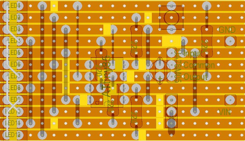 lusty wind
glacial cobalt
Only these imgs
https://imgur.com/a/ladder-rage-2ppJn
lusty wind
glacial cobalt
Only these imgs
https://imgur.com/a/ladder-rage-2ppJn
That's rather unfortunate, but maybe you're more familiar with working with this kind of information than I am. I'm used to using a schematic. The author "Can't grantee this is mistake free." which isn't gratifying.
So, I'll be honest with you, I'm not going to debug this diagram for you. It looks like one side of groups of three LEDs are connected together, but then every fourth is connected in series with the common wire of the previous three. Like the fourth down from the top. Then there's that weird crossover between LED 9 and 10. I have no idea what that's about. Normally I'd think all of the cathodes of the LEDs would be connected together and the anodes would go to whatever is controlling them.
If you can contact the author (they suggest you can) they might be able to elucidate what's the intention of all those crossovers. I can't make it out.
undone tangle
undone tangle
Hello! I'm a complete noob to electronics and whatnot, and I'm looking to make a...
Anywhere else I could possibly ask for help with this? Ive tried reddit and the adafruit forums
buoyant jackal
undone tangle
Anywhere else I could possibly ask for help with this? Ive tried reddit and the ...
We have a number of helmet projects: https://learn.adafruit.com/search?q=helmet
If you want to animate the eyes, we have two products: https://learn.adafruit.com/search?q=monster%2520m4sk and https://www.adafruit.com/search?q=glasses
glacial cobalt
lusty wind
That's rather unfortunate, but maybe you're more familiar with working with this...
Hopefully I can contact the owner but the video he made is like 9 years old but I’ll see
 plucky sail
Hi I was trying to get a QT Py S3 in a rotary lineman test phone Can I stack the Audio BFF Add-on for QT Py with the LiIon or LiPoly Charger BFF to work together?
buoyant jackal
plucky sail
Hi I was trying to get a QT Py S3 in a rotary lineman test phone Can I stack the...
The LiPo BFF has voltage monitoring on pin A2, and the Audio BFF also uses A2. But you can cut a jumper on the LiPo BFF to stop using A2.
do you need the SD card socket on the Audio BFF. Another similar set of functionality is the RP2040 Feather Prop-Maker, which has built-in charging circuitry and an audio amplifier
The Adafruit Feather series gives you lots of options for a small, portable, rechargeable microcontroller board. By picking a feather and stacking on a FeatherWing you can create advanced ...
plucky sail
buoyant jackal
The LiPo BFF has voltage monitoring on pin A2, and the Audio BFF also uses A2. B...
Thank you , just seeing that the A2 would be a conflict , And I have thought about the the RP2040 Prop-maker but I want to be able to still have WiFi for like a mp3 server access point type idea.
buoyant jackal
plucky sail
Thank you , just seeing that the A2 would be a conflict , And I have thought abo...
if you need the monitoring you might be able to jumper to an unused An pin
plucky sail
buoyant jackal
if you need the monitoring you might be able to jumper to an unused An pin
The SD card takes the last A0
 vernal pine
can I cut this? need it to be a specific length.
 white marsh
vernal pine
can I cut this? need it to be a specific length.
white marsh
vernal pine
can I cut this? need it to be a specific length.
Yes if you click through to the datasheet from the product page it says "each small section can be cut off" and by that I believe the mean here...

But of course you are limited to multiples of whatever that length is between the pads.
vernal pine
thank u!
 stable minnow
I want to use the soft flexible neopixel strand - 50 pixels with a microbit. Is it possible to use a 5V power supply instead of a rechargeable battery? Is this safe for the microbit or will it damage it?
buoyant jackal
stable minnow
I want to use the soft flexible neopixel strand - 50 pixels with a microbit. Is ...
this is fine. Connect only the strip +V to the 5v. Tie of the 5v supply to the board ground. You can drive the data input on the strip from the 3.3V output of a pin, but it will be marginal. If it works, it works. If not, you would need a 3.3V - 5V level shifter. Any easy one to use is https://www.adafruit.com/product/5888

Whenever we're working with 'true analog' LED strips, that have 1-3 channels of RGB or White LEDs, we wish we had already invented to make wiring them easier: ...
stable minnow
buoyant jackal
this is fine. Connect only the strip +V to the 5v. Tie of the 5v supply to the ...
Thx! I seem to need access to that link you provided.
buoyant jackal
stable minnow
Thx! I seem to need access to that link you provided.
sorry, wrong link! edited
 dense atlas

I wanna make this ready for permanent use. I'm planning on printing a 3D to cover it, before i do that i have a couple of goals:
- The wires are too long and all over the place (Male to Male). I want them shorter, just enough to function correctly, in the same positions obviously
- I want the board to powered without a USB to the computer. I'm sure either a battery or a wall outlet would work for this, but let me know what you think would work best. I'd prefer a battery but at the same time It should perform over 24 hours with no charge
lusty wind
dense atlas
I wanna make this ready for permanent use. I'm planning on printing a 3D to cove...
What you might consider is using a Perma-Proto board for your final implementation
https://www.adafruit.com/product/1609
creating a socket for your Feather (don't solder it in) using female headers. You can power it via a battery, but also via a 5V USB charger, which are cheap.

Customers have asked us to carry basic perf-board, but we never liked the look of most basic perf: it's always crummy quality, with pads that flake off and no labeling. Then we thought ...
But make sure you get headers that are the right size for your Feather (I don't know how many pins yours has, I think all Feathers are the same by definition).
https://www.adafruit.com/product/2940

These two Short Female Headers alone are, well, lonely. But pair them with any of our Feather boards and you're in business!These headers are particularly ...
dense atlas
lusty wind
What you might consider is using a Perma-Proto board for your final implementati...
Why don't solder?
Also how do I make the wires shorter and permanent
buoyant jackal
dense atlas
Also how do I make the wires shorter and permanent
if you need to replace the Feather, then it will be a lot of work to unsolder it. So it's more serviceable if you make a socket for it.
dense atlas
Ok
buoyant jackal
Instead of using jumper wires, you can buy solid hookup wire (22 or 24 gauge, say), and cut jumpers to fit. You'll want a wire stripper to remove the insulation. Continuing your Micro Center shopping:
https://www.microcenter.com/product/456250/adafruit-industries-hook-up-wire-spool-set-(22awg-solid-core-25-ft)
https://www.microcenter.com/search/search_results.aspx?N=&cat=&Ntt=wire+stripper&searchButton=search
pick a wire stripper that includes 22 and 24 gauge in its range
YOu can also buy pre-cut wire jumpers:
https://www.microcenter.com/product/639727/inland-ks0334-keyestudio-box-packed-140-breadboard-jumper-wire-bundle-3pcs
but the lengths will not be exactly right.
Then you solder these jumpers to the Perma-Proto board
lusty wind
dense atlas
Why don't solder?
In addition to what @buoyant jackal has said, the Feather is by far the most expensive part on your project. If for any reason the project doesn't work and you can't fix it, or in the future you no longer want to use the project, you can always just pull the Feather out of the socket and use it for something else. I never solder my expensive parts, and I have a box of old unused projects with empty sockets... 😄
dense atlas
If i don't solder it woin't it be like a bad connection
lusty wind
dense atlas
If i don't solder it woin't it be like a bad connection
You will need to solder the female headers to make a socket for the Feather, yes. Good electrical connections require soldering.
lusty wind
dense atlas
thank you all
Have fun!
buoyant jackal
dense atlas
ima get these parts tmmr
microcenter doesn't seem to have regular female headers in stock. They do have "stacking headers"; you could cut off the long pins. https://www.microcenter.com/search/search_results.aspx?N=&cat=&Ntt=stackable+headers

 white marsh
dense atlas
white marsh
dense atlas
Those all look like good prices and things even if you don't use them for this project can/will be used later.
white marsh
dense atlas
Do they have any stackable header with more pins than shown there? 'Cause you can shorten longer ones to the number of positions needed. Often the longer ones (number of pins) are not much more than the shorter ones.
cunning saffron
I think they often come in lengths of 20, then you can remove a pin, cut to desired length, then file the ends if desired. There are packs at various places made specifically for Feather with a 12 and a 16.
dense atlas
white marsh
Do they have any stackable header with more pins than shown there? 'Cause you ca...
they’re not in stock so dahn told me to just ge those and trim it
Unfortunately after an entire day of driving i couldn’t find the 24 awg wire
I went to autozone lowe’s and home depot and micro center none had them
dense atlas
all good though they're coming tommorow
buoyant jackal
dense atlas
the flex perma proto board is OK but be careful not to bend it a lot. MC had an assortment of regular Perma-Proto boards, but the "normal" ones were out of stock
dense atlas
So can I place the wires the same way as on the breadboard?
I'm gonna start now
But the breadboard has the holes connected on the + and - railings and then vertically on the inside, is the permaboard the same?
 buoyant jackal
dense atlas
But the breadboard has the holes connected on the + and - railings and then vert...
buoyant jackal
dense atlas
But the breadboard has the holes connected on the + and - railings and then vert...
The perma proto is the same: the top and bottom +/- rails are connected horizontally, and then the holes for the devices are connected vertically
dense atlas
oh ok
So i stuff the copper in the hole and solder it basically to make a connection
buoyant jackal
yes, you put the pins in on the top side of the perma proto, and solder on the bottom side
dense atlas
ok
buoyant jackal
If the flex board is flexing too much, you might want to tape popsicle sticks or similar to the edges to keep it from flexing
dense atlas
Not home rn but i did the power and gnd wire and when i connect the board via usb the pc just refuses to find it
As soon as i remove it from the socket it works
noble fossil
dense atlas
As soon as i remove it from the socket it works
check the connections on the socket carefully. you might have shorted together pwr and gnd. or if you soldered the socket directly to one of the power rails, it would short out (i can’t see the exact placement)
minor snow
minor snow
Another option could be to fork https://learn.adafruit.com/fruit-jam-nintendo-en...
Continuing the brainstorming process that I'm replying to, does that example project for the Fruit Jam have enough headroom to emulate at 10× the clock frequency of the original NES, split between two separate W65C02S microprocessors (one at 2×, and the other at 8×)?
minor snow
minor snow
Continuing the brainstorming process that I'm replying to, does that example pro...
Given that it was forked from a similar RP2040 project, which both lacks hardware-accelerated TMDS encoding and utilities lower-end microcontroller cores, it does sound like it should have some amount of computational headroom. However, I don't know whether it'd be enough.
 daring totem
im looking for a motion switch for 5v battery toys im converting to electric, thats all complete but i want some small photo eyes to put in them am
nd not the big switches that are 1'' by 2-2 1/2' long. any ideas out there?
 cobalt wedge
I have a situation where I have an INA238 power sensor that is doing the power calculation wrong. As in, I'll request power, voltage, and current, and it'll respond with:
Voltage: 9.978 V
Current: 967.041 mA```Has anyone else seen this? I'm using the Adafruit INA237 and INA238 Library, so I'm hoping someone else has used this and maybe seen something
dense atlas
@buoyant jackal
I don't need to create a prototype board or whatever can't I just order a PCB?
buoyant jackal
dense atlas
I don't need to create a prototype board or whatever can't I just order a PCB?
you could but you have to get it right. So if you're prototyping, it's a lot easier to use a board you can change
dense atlas
Idk i just don't see why I wouldn't just use a breadboard for that
I'm using the breadboard to get my wiring and then once i'm finally done i'll just design it on kicad and get a PCB
The proto board is lowkey useless
buoyant jackal
it saves time, and you can change it later. getting a board made is not so cheap
buoyant jackal
depends on the size
dense atlas
My board is hella simple
All I really need is the wiring and then headers
And the feather m4 and sensor i cna just transfer over like a socket
buoyant jackal
once your soldering skills are better, it will take less time to solder it up than design the board
dense atlas
even if i do a proto board i'm still gonna end up ordering a PCB
buoyant jackal
dealing with the flex board is a nuisance. a regular perma-proto would be easier
dense atlas
buoyant jackal
dealing with the flex board is a nuisance. a regular perma-proto would be easier
i was gonna say
The flex board was so irratating to solder with
buoyant jackal
(I would have told you not to buy it 🙂 )
dense atlas
Rip
Well anyways now im scrapping the whole proto board stuff
I have one more problem with my board
and that's the fact that it needs a wired connection to send data
I need to send the data over wireless via bluetooth or wifi somehow and i'm pretty sure the m4 can't do that by itself so once i fix that i'll older a pcb and 3d print a cover for it
buoyant jackal
you can use a Feather ESP32-S3 (wifi or BLE) or a Feather nRF52840 (BLE only). If you don't need the battery connection and charger you can use a QT Py form factor, even smaller
 lost swallow
Is it possible to use a 3s and 2s lipo power source?
Diodes to prevent overcharging of the 2s source
Would this make it so the 3s source would drain first and then the 2s source?
The goal is to have a hot swappable battery while keeping the onboard battery charged
dense atlas
I know it's nothing crazy but cus of yall I was able to do this. Thank you so much

This is like my first ever project like this. It's interesting to see like real world data and being able to visualize it like that
cobalt wedge
cobalt wedge
Has anyone else seen this? I'm using the Adafruit INA237 and INA238 Library, so...
I found the issue and submitted a PR: https://github.com/adafruit/Adafruit_INA237_INA238/pull/2

GitHub
The Power register is 3 bytes wide, rather than 2. Also the datasheet has a multiplier of 0.2x rather than 20x.
 sand urchin
Hey everyone, I was looking at starting a project and I was wondering if anyone has done something similar. I am looking at building a notification system for my garage door being left open.
I am wondering if anyone has done something like this before. I am thinking either going with a distance based sensor or one of those magnetic contact switches. Looking to send me a text notification whenever the status changes (opened, closed) and allow me to text it to get an update of the status. Just looking for thoughts or possible road blocks I might hit when diving into this if someone has been here before.
Thanks 🙂
 gritty birch
sand urchin
Hey everyone, I was looking at starting a project and I was wondering if anyone ...
gritty birch
sand urchin
Hey everyone, I was looking at starting a project and I was wondering if anyone ...
This is totally a thing I've heard of people doing, but I don't have hands-on experience. You could have multiple sensors too, in case one is less reliable. Re: text message, that's a little harder unless you're hooked into some other framework/tooling that will do it for you. Adafruit has their IoT service, Adafruit IO, that can do SMS, though there are other options out there.
lusty wind
sand urchin
Hey everyone, I was looking at starting a project and I was wondering if anyone ...
For such a system to be able to text it would need to actually include a phone or the equivalent of a phone, and you’d need to pay your phone company for another device on your account.
But if you’re willing to forgo the notification and check a web page, it’s relatively easy to set up something like that by creating a small web server. But you’d need to punch a security hole in your local network modem so that would require hardening the server you create.
Anything you do to make it easy for you to gain access to devices on your home network does the same for others.
fleet terrace
sand urchin
Hey everyone, I was looking at starting a project and I was wondering if anyone ...
My garage has no windows, so I use a light sensor and ESP32. It detects when a light change occurs: could be sunlight or the light.
For notification, I use a Discord webhook to a private channel on a private server.
Currently, I do the webook through Adafruit IO. But I could have also done it directly.
gritty birch
lusty wind
For such a system to be able to text it would need to actually include a phone o...
If the device has to send the SMS messages, that's correct, but if it's acceptable to use a third party webservice, there are plenty. I've used twilio, for example
 stable barn
sand urchin
Hey everyone, I was looking at starting a project and I was wondering if anyone ...
stable barn
sand urchin
Hey everyone, I was looking at starting a project and I was wondering if anyone ...
Have a look at Katni's wifi mailbox tutorial for some ideas. Adafruit IO+ can send SMS https://learn.adafruit.com/wifi-mailbox-notifier?view=all

Never check an empty mailbox again!
sand urchin
Thank you to all who replied with some information! Going to be doing this project over the holidays here in a bit! Excited to get started on it and will make a post along the way! 🙂
 vivid plinth
Has anyone else run into an issue with extra power use after flashing new firmware on a board that uses the Adafruit nRF52 bootloader?
I have a custom PCB using an nRF52840, and I've flashed it with a build of the nRF52 bootloader which I've customized to use the correct LED and button pins. The commit I built it from is up to date with the latest commit on https://github.com/joelspadin/Adafruit_nRF52_Bootloader. If I flash new firmware, disconnect USB, and measure the power usage at the battery pins using a Nordic PPK2, I get a 10 second average of ~390 uA. If I cycle power and measure again, I get ~45 uA.
I have observed the same thing happening on a nice!nano v2 running stock ZMK firmware, so I'm pretty sure it's not an issue with my hardware. It could be an issue with ZMK, but the fact that it only happens directly after flashing new firmware points more towards the bootloader. Is there anything the bootloader might configure when flashing and fail to reset when done that could cause extra power use?
 wintry patio
hey how do you guys paint your 3d prints, I sanded down my 3d print made with PLA plastics and tried to paint it with acrylic paint and the acrylic paint is like leaving behind bubbles/watery
is it okay to use spray paint, I might just run tot he hardware store tomorrow and get some
lusty wind
wintry patio
hey how do you guys paint your 3d prints, I sanded down my 3d print made with PL...
Acrylic paint won't stick to plastics without a proper primer. But any acrylic enamel will work fine on plastics.
gritty birch
wintry patio
is it okay to use spray paint, I might just run tot he hardware store tomorrow a...
grab a spray primer
buoyant jackal
vivid plinth
Has anyone else run into an issue with extra power use after flashing new firmwa...
Could you open an issue? https://github.com/adafruit/Adafruit_nRF52_Bootloader/issues. It does sound like a chip peripheral or power setting that is not being hard-reset after loading a UF2.
If you just press the reset button as opposed to power-cycling, does that also fix the power consumption?
vivid plinth
Usually pressing reset does lower the power consumption, though one time I noticed it dropping from ~400 uA to only ~150 instead of ~40 as expected, and then when I cycled power it returned to ~40. Will file an issue. I can also help debug if you have any ideas for what might get enabled only when flashing, that I can try to check if they're still enabled afterwards.
buoyant jackal
vivid plinth
Usually pressing reset does lower the power consumption, though one time I notic...
given that a power cycle fixes the problem, is there an issue with just documenting that for your purposes, or is it inconvenient to do that?
Does your board have an RGB LED?
vivid plinth
It does work to cycle power, but given that it seems to affect other boards and not just my own, it would be nice if I could figure out why and fix it for everyone. This could explain some of the reports we've gotten of keyboards running out their batteries unexpectedly quickly with ZMK firmware, since nrf52s using the Adafruit bootloader are very popular there.
No RGB LED. Just a single reset button and a single color status LED.
vivid plinth

GitHub
Operating System Windows 11 INFO_UF2.TXT UF2 Bootloader 0.4.1-265-g4723240 lib/nrfx (v2.0.0) lib/tinyusb (0.12.0-145-g9775e7691) lib/uf2 (heads/master-28-gb19ac9a) Model: Marten Numpad Board-ID: nR...
floral hinge
Hello, all you awesome folk! I'm having troubles with my QTPY ESP32-S2 board. I previously rewrote the bootloader to run it from Arduino, but now want to go back to CircuitPython. I've followed the recovery procedure shown on https://learn.adafruit.com/using-open-installer-on-circuitpython-org by using the Open Installer for the QTPY from https://circuitpython.org/board/adafruit_qtpy_esp32s2/ ... This shows that it's able to erase the QTPY, and that it completes programming it.. But when it's done, it doesn't ever reset the QTPY.. And when I manually reset the board after programming is finished, the board briefly flashes the LED red, then solid green. Nothing ever shows up on the serial port which is listed in Device Manager, but yet the QTPY never shows up as a drive on the system, either.

The Web Firmware Installer can install the TinyUF2 bootloader and CircuitPython
I've tried both the "Install Bootloader Only" and the "Install CircuitPython 10.0.3 Bin Only" methods. I figured since I don't get a drive to drop U2F firmware onto, that trying the Full Install or U2F install wouldn't help much.
Ah crud. Disregard!! The device IS showing up as a drive, I just hadn't noticed it!
Gotta love answering your own question with such ease! 😆
 rugged vigil
Howdy, all. Looking for a recommendation for very small e-ink display to hang off an ESP32-S3 running CircuitPython. The goal is to have a very low current-draw system that will wake up once or thrice an hour, take a measurement, and update the display (which I assume is persistent). Any pointers? Thanks.
 molten iris
rugged vigil
Howdy, all. Looking for a recommendation for very small e-ink display to hang ...
molten iris
rugged vigil
Howdy, all. Looking for a recommendation for very small e-ink display to hang ...
The easiest solution is a Featherwing, but only 1 out of 4 is in-stock: https://www.adafruit.com/search?q=e-ink&c=956 - if you search for other e-ink devices on adafruit.com, each should mention whether it works in CircuitPython. It really depends on how much wiring you want to do and what size screen you need
Adafruit Industries, Unique & fun DIY electronics and kits : Search Results - Tools Gift Certificates Arduino Cables Sensors LEDs Books Breakout Boards Power EL Wire/Tape/Panel Components & Parts LCDs & Displays Wearables Prototyping Raspberry Pi Wireless Young Engineers 3D printing NeoPixels Kits & Projects Robotics & CNC Accessories Cospla...
buoyant jackal
some are in stock at Digi-Key.
fleet frost
Hi I have a jst ph female 2 pin that is attached to my lipo battery, I want to be able to attach this to my boost converter or even just the breadboard. How would I do this, the holes don’t fit normal pins and headers
 lone tree
fleet frost
Hi I have a jst ph female 2 pin that is attached to my lipo battery, I want to b...
lone tree
fleet frost
Hi I have a jst ph female 2 pin that is attached to my lipo battery, I want to b...
use this: https://www.adafruit.com/product/3814

For a really long time we assumed that the JST PH didn't have a free-hanging male header version. But then we found this JST-PH 2-pin Male Cable, and we were like, this is perfect! ...
just make sure to verify polarity! different battery connector use different conventions - some put positive on pin1 , some on pin2
lusty wind
lone tree
just make sure to verify polarity! different battery connector use different con...
And for god's sake do not rely on wire color! 😱
fleet frost
Is there a way to shorten the wires to make everything compact . I’m planning to add this to a small portable project.
lone tree
you can always just cut off the existing connector and solder another one, or solder wires directly to the PCB.
but be careful - I once made the mistake of cutting both wires on a battery connector in one cut, so my scissors shorted the battery. believe me, you don't want that
fleet frost
Thanks
lusty wind
fleet frost
Is there a way to shorten the wires to make everything compact . I’m planning to...
Another option is just to coil the wires. That saves a lot of time and trouble.
 brave mason
Learning Assembly for PICO any help???
lusty wind
brave mason
Learning Assembly for PICO any help???
Your question is a bit vague. Help for what? What purpose do you have either for using the Pico, or learning assembly? ...and I assume you mean assembly for the PIO?
brave mason
lusty wind
Your question is a bit vague. Help for what? What purpose do you have either for...
Well yeah sry for the vague details I'm learning Assembly language and I am currently using RP2040 for learning it
lusty wind
brave mason
Well yeah sry for the vague details I'm learning Assembly language and I am curr...
The Raspberry Pi Pico uses the RP2040 as its processor, which has two ARM Cortex-M0+ cores which, yes, you can program in assembly. I believe the documentation is found in the Pico SDK, though you're digging a bit deeper than I've gone on the chip so I can't really help you with the details: https://pip-assets.raspberrypi.com/categories/610-raspberry-pi-pico/documents/RP-008354-DS-1-raspberry-pi-pico-c-sdk.pdf
[one nice thing about the Raspberry Pi Foundation: they provide very nice documentation]
So... you asked "any help?" Any help for what? Is it a good choice for learning assembly, or what question are you asking?
brave mason
lusty wind
The Raspberry Pi Pico uses the RP2040 as its processor, which has two ARM Cortex...
Actually I heard that assembly can help me program the PIO more efficiently soo i think of learning it
lusty wind
brave mason
Actually I heard that assembly can help me program the PIO more efficiently soo ...
Each processor's assembly language is both similar and different, some more than others. I first learned 8008 assembly in 1979, then moved on to Z80 and 68000. That 8008/8080/8085/Z80 family is still around in the MCS-51 (AKA 8051) chips, which are found in lots of places (Adafruit and Pimoroni both uses them in their products; Nuvoton are a major OEM manufacturer of them). https://en.wikipedia.org/wiki/Intel_MCS-51
The PIO (Programmable I/O) isn't programmed in ARM assembly, it has its own low-level assembly language. The PIO is a bit like an FPGA but simpler. It's certainly something very valuable to know how to program though, as it can be a very powerful tool. Considering how low-cost an RP2040 it, it's kinda amazing to think there are two PIOs available.

The Intel MCS-51 (commonly termed 8051) is a single-chip microcontroller (MCU) series developed by Intel in 1980 for use in embedded systems. The architect of the Intel MCS-51 instruction set was John H. Wharton. Intel's original versions were popular in the 1980s and early 1990s, and enhanced binary compatible derivatives remain popular today. ...
brave mason
lusty wind
Each processor's assembly language is both similar and different, some more than...
Yeahh that's why i kinda love to learn it and can you plz share any doc regarding assemble with me plz
lusty wind
brave mason
Yeahh that's why i kinda love to learn it and can you plz share any doc regardin...
Like I said, the think the reference for the RP2040 is the Pico SDK document I linked.
brave mason
lusty wind
Like I said, the think the reference for the RP2040 is the Pico SDK document I l...
Okk thanks for your help
 sleek yacht
hey i but this "https://www.amazon.com/dp/B0CJYBRK3M?ref=ppx_yo2ov_dt_b_fed_asin_title" on amazon and can't seam to get it to print English via python using uart via the raspberry pi 4 b. is there a way to print via the usb port on windows via python?

- SPECIFICATIONS: 58mm embedded thermal printer with excellent performance and clear printing, widely used in medical equipment, testing instruments, etc.
- COMPATIBILITY: This thermal printer can be connected to MCU, for , for , forsystem, making it easy to print text, , barcodes, QR codes, et...
 neon pumice
I have a weatherproofing challenge: I'm planning on putting a couple of R Pis on a bike along with a 12.5 x 6" LED display and I want to be able to ride with them working in the rain. any tips? one R Pi has a bonnet with a display and push buttons which I would like to be able to see/operate in the rain. the other R Pi will be next to the large LED display which I want to be visible in the rain.
I'm thinking I could wrap components in some kind of clear flexible plastic and maybe I use a heat gun to make it hold shape. and maybe some kind of putty or weatherproof connector around where cables need to enter. I would use weatherproof DC to DC connectors for cable runs because I don't want to have the kit installed on my bike 100% of the time

Bring a little bit of Times Square into your home with this sweet 64x32 square RGB LED matrix panel. These panels are normally used to make video walls, here in New York we see them on the ...

If you'd like a compact display, with buttons and a joystick - we've got what you're looking for. The Adafruit 128x64 OLED Bonnet for Raspberry Pi is the big sister to our ...
floral hinge
Anyone know of a way to panel-mount a single WS2812/Neopixel LED? 5mm would be fine.. I love the look of these (https://www.adafruit.com/product/2176) but I don't think they'd work with the 5mm Neopixel Diffused item, because there's 4 legs on the LED instead of 2.

Keep your 5mm LEDs in place with these chromed metal LED holders. These are handy for projects using individual LEDs as they look sleek, and your LED won't budge. ...
buoyant jackal
floral hinge
Anyone know of a way to panel-mount a single WS2812/Neopixel LED? 5mm would be f...
https://www.adafruit.com/product/2175 and https://www.adafruit.com/product/2174 are snap fit and the leads don't need to go through anything

Keep your 5mm LEDs in place with these little plastic LED holders. These are handy for projects using individual LEDs as they look sleek, and your LED won't budge. Slot the LED ...

Keep your 5mm LEDs in place with these little plastic LED holders. These are handy for projects using individual LEDs as they look sleek, and your LED won't budge. Slot the LED ...
These have four holes https://www.adafruit.com/product/2178

Keep your 5mm LEDs in place with these chromed metal LED holders. These are handy for projects using individual LEDs as they look sleek, and your LED won't budge. ...
https://www.adafruit.com/product/2176 might only have two holes (it's hard to see, but you could drill extra holes for the leads in the plastic insert
floral hinge
Oh, sweet, I hadn't noticed that the chrome bevel ones had 4 holes!! THank you!
buoyant jackal
floral hinge
Oh, sweet, I hadn't noticed that the chrome bevel ones had 4 holes!! THank you!
https://www.adafruit.com/product/1938 have four leads in a row, but maybe you can bend to fit the 4-hole bevel holders

LOLwut? NeoPixels in 5mm through-hole variety? Oh yes, we haz them! If you like NeoPixel strips you'll luv these 5mm diffused through-hole NeoPixels. All the ...
there may be an issue with getting it to fit nicely. YOu could also just drill out the plastic part larger, so all four leads could fit through without hindrance
or replace the plastic part with a short piece of rigid plastic tubing or something. Could 3d print something
floral hinge
I'll give that a whirl. Thanks again!
minor snow
floral hinge
Anyone know of a way to panel-mount a single WS2812/Neopixel LED? 5mm would be f...
Also, if you're able to be flexible regarding the exact mounting mechanism (maybe https://www.adafruit.com/product/3299 or adhesive?), I think https://learn.adafruit.com/flora-rgb-smart-pixels is likely to require less effort overall.

Totaling 380 pieces, this M2.5 Screw Set is a must-have for your workstation. You'll have enough screws, nuts, and hex standoffs to fuel your maker tendencies for days on ...

Addressable, chainable, delectable!
 young pier
This diagram is from a student's diff eq exam -- an "application" question. There is some explanatory prose saying that V_out is the back-emf of the motor and V_in is a time-varying voltage coming from a power supply, and giving the diff eqs that come from Kirchoff's law on the circuit and torque = I*alpha on the motor shaft. It seems like the professor is expecting students to plug-and-chug without domain knowledge (there is no physics or EE prerequisite), which I don't like -- we shouldn't be teaching students to try to model things without having any understanding of the domain.
Ok, all that said, I'm a noob, is this a sane circuit design? Two things I notice are: (1) there is a separate inductor in series with the motor -- what's the point of that? (2) there is no flyback diode... is the inductor supposed to do flyback protection or something?

I originally thought the inductor and resistor in the schematic were just to model the resistance and self-inductance of the coils in the motor, but I'm no longer sure.
ah, the instructions say it's a DC motor
mighty walrus
to me that feels more like a model of the process than a design to be built
so e.g. it'd be a nice physics problem to have the students calculate for example the situations in which the current would run backwards (which should be alarming), thereby motivating the use of a diode
but I think it might be too hard of a problem in an exam context if you had to start from e.g. Maxwell's equations
in particular, relating the motor motion or torque to dflux/dt seems gnarly and there'd be a side-track that I think a lot of students would get stuck in of trying to do the calculation in a geometric way (e.g. 'how do I know how many wire loops the stator has? How do I know the field from the permanent magnets surrounding the stator?' sorts of things)
young pier
Right so, there is supposed to be no physics prerequisite for this class, and they don't explain how an inductor works. They do give the differential equations governing the operation of each component, for example V = L dI/dt for an inductor. The question seems crazy to me though, because for example, how the heck is the student even supposed to know how the two diagrams relate to each other. It is mentioned in symbols lower down in the question, but never do they explain that the motor shaft is physically connected to (or within the concentrated magnetic field of) the V_out component. My basic thesis is that this is not a reasonable "application question" for a diff eq class
They just say "the component of torque from the motor is proportional to the current via an electromechanical transduction constant k." That is a comprehensible sentence if and only if you know something about the domain
white marsh
rugged vigil
Howdy, all. Looking for a recommendation for very small e-ink display to hang ...
HI Spencer, all the Adafruit sold ePaper displays can be found here: https://www.adafruit.com/category/150 but I am chiming in to answer your question that yes, the display is persistent when the ESP goes to sleep. I have a 2.13" one running on my desk off a Qt Py ESP32-S3 and to further reduce power when the Qt PY is sleeping, the ePaper uses such a low current even when actively updating, that I am powering it off one the Qt Py GPIO pins rather than feeding it 3.3V from the pin on the Qt Py. So when mine sleeps, the display is also powered down completely. Works great.
Adafruit Industries, Unique & fun DIY electronics and kits : eInk / ePaper - Tools Gift Certificates Arduino Cables Sensors LEDs Books Breakout Boards Power EL Wire/Tape/Panel Components & Parts LCDs & Displays Wearables Prototyping Raspberry Pi Wireless Young Engineers 3D printing NeoPixels Kits & Projects Robotics & CNC Accessories Cosplay...
rugged vigil
Thanks! That's useful info. I ordered a few units, and will get one of my test boards up and running with it after it arrives. Appreciate the help!
sleek yacht
sleek yacht
hey i but this "https://www.amazon.com/dp/B0CJYBRK3M?ref=ppx_yo2ov_dt_b_fed_asin...
my question still needs to be answered.
neon pumice
sleek yacht
my question still needs to be answered.
since it's product-specific and not made by Adafruit, this might be a better question for customer support of the manufacturer. try to get it working within the return window heh
neon pumice
neon pumice
I have a weatherproofing challenge: I'm planning on putting a couple of R Pis on...
@stable barn do you have opinions? 😛
stable barn
neon pumice
<@462694143861456896> do you have opinions? 😛
seems tough, not impossible. bikes have a tendency to spray water everywhere all the time.
Fenders and enclosures with Ingress Protection (IP) ratings
Once you wrap the electronics too much you have to start worriing about condensation.
Good luck!
lone tree
neon pumice
yeah it's definitely gonna be a learning experience
check waterproof pouches used by kayakers e. g. for maps
like this one https://a.co/d/fN5u1jj

KOSIBATE Map Case, Waterproof Military Hiking Map Pouch Holder with Clear Window & Lanyard
neon pumice
ooh that’s an excellent idea for the display, thanks!
 lunar cedar
I feel useful and productive and nearly done with this 'alternate interface' clock project. I still need to sus out a neopixel glitch that pops up when charging the onboard 'power failure' batteries. I still need to wade through CPy's time zone stuff. But nearly everything else is ready for a 0.0.99 release.
 buoyant oar
Hi seniors,
I made a huge mistake by inputing wrong information while sign up with varsity student account. Now Autodesk know I made wrong info so it showing that I need to input student transcript docs.
I rushed to get fusion360 for project and made this huge problem
minor snow
buoyant oar
I rushed to get fusion360 for project and made this huge problem
Unless you're taking a course that has a strict requirement, maybe look into one of these: https://alternativeto.net/software/fusion-360/?license=opensource

AlternativeTo
The best open source alternative to Autodesk Fusion is Blender. If that doesn't suit you, our users have ranked more than 25 alternatives to Autodesk Fusion and 12 is...
 narrow epoch
I’m having trouble finding a 6.5 x 1.5 inch LCD display. I know that’s a very unconventional size, but does anyone know if there’s something pretty close to that?
The plan is to put that display in a U-Matic cassette
 gritty birch
narrow epoch
The plan is to put that display in a U-Matic cassette
gritty birch
narrow epoch
The plan is to put that display in a U-Matic cassette
I think you'd pay more to get the right size vs using a wrong size and just covering some of it
narrow epoch
Yeah, something a little larger or smaller would be great, but I'm only finding screens that are more than double what I need
 sterile dock
Hello, I have been tempted to use the VEML6075 for a project of mine but realised it didn’t come with the printed circuit I thought it would. Do you think I can make it work like Adafruit ? I know it has been discontinued but I don’t know if it’s possible to create a home-grown captor that is usable with Arduino. If it is possible, what components do I need ? How should I connect them together ? Are their major obstacles I must be made aware when creating a similar card to Adafruit’s ?
cunning saffron
@sterile dock does this help? https://github.com/adafruit/Adafruit-VEML6075-UV-Sensor-PCB
buoyant jackal
narrow epoch
Yeah, something a little larger or smaller would be great, but I'm only finding ...
https://newhavendisplay.com/ has a lot of options. Are you looking for a pixel display or a character display
narrow epoch
buoyant jackal
<https://newhavendisplay.com/> has a lot of options. Are you looking for a pixel...
Thanks I’ll check that out! Ideally it would be pixel, but character can work.
 upper bloom
Playing with a new Fruit Jam, and I noticed this on the downloads page. Is this an error? I don't see an EYESPI connector...
 buoyant jackal
upper bloom
Playing with a new Fruit Jam, and I noticed this on the downloads page. Is this ...
buoyant jackal
upper bloom
Playing with a new Fruit Jam, and I noticed this on the downloads page. Is this ...
I opened a PR to fix that -- thanks.
 digital fossil
Can I use the GPIO on a raspberry pi 3b+ like an arduino? I didn’t see it on the circuit python website. I don’t know how to program it. I’m trying to use it in a project originally meant for the UnoR4 WiFi but I already have the raspberry pi
Ah I just found this https://learn.adafruit.com/circuitpython-on-raspberrypi-linux/overview

Make hardware and interface with sensors super easy using CircuitPython libraries
upper bloom
digital fossil
Can I use the GPIO on a raspberry pi 3b+ like an arduino? I didn’t see it on the...
There are some limitations on the Pi GPIO compared to an Arduino, but for most general purposes they’re plenty capable enough.
Do you have a project link for reference? Something built for the R4 WiFi won’t port very easily to a Pi, you’ll most likely have to rebuild most of the code.
fleet frost
Hi right now I am charging my 3.7v lipo and want to know how to see the current voltage. Also I am using this charger https://www.microcenter.com/product/504052/adafruit-industries-mini-lipo-w-mini-b-usb-jack-charger and I want to know if it can detect and automatically stops charging when it reaches the limiting voltage of 4.25. And on the board is there a way to output the voltage of the battery. I want to power my boost converter but I also want to leave the battery in the charger. Is there a way?

 upper bloom
fleet frost
Hi right now I am charging my 3.7v lipo and want to know how to see the current ...
upper bloom
fleet frost
Hi right now I am charging my 3.7v lipo and want to know how to see the current ...
The charger should automatically stop once the battery reaches ~4.2V. This is a fixed voltage based on the MCP73831-2 IC used on this charger.
There are holes you can solder headers or wires to in order to access the battery while it's plugged in the charger. You can wire these to your boost converter input to draw power from the battery.
 fleet frost
Thanks. Just to clarify if I solder headers onto the charger will it still work even if the charger is not plugged via microusb. I just want the battery to go through the header. Also what does the bat marking mean. I can assume that gnd is ground but will bat work as input for my converter
upper bloom
BAT connects directly to the battery +. Will work regardless of USB input.
5V is the USB input + and will not provide power when USB is unplugged.
fleet frost
Thanks
sterile dock
cunning saffron
<@620289714129338399> does this help? <https://github.com/adafruit/Adafruit-VEML...
I’ve checked it a bit and wasn’t sure where to look for, I will make more research there, then, thank you.
I am looking to identify the pieces of the hardware I am missing but the link doesn’t seem to give the circuit used.
cunning saffron
@sterile dock Adafruit learn guides usually have a schematic https://learn.adafruit.com/adafruit-veml6075-uva-uvb-uv-index-sensor/downloads
sterile dock
cunning saffron
<@620289714129338399> Adafruit learn guides usually have a schematic <https://l...
Thank you very much, it’s the first time I go through Adafruit’s Website. Thank you for your patience.
 forest steeple
Hey! Has anyone done anything with APRS (Amateur Packet Reporting System)? I'm looking to build a weather balloon and want to track it across the globe (if you have non APRS recommendations, I'm all ears)
dusky lion
forest steeple
Hey! Has anyone done anything with APRS (Amateur Packet Reporting System)? I'm l...
(I'm assuming you're a ham?) I haven't worked with balloon projects but follow some folks who do. I see people shift to WSPR from APRS - https://www.picoballoons.net/trackers/wspr-tracker could be a starting point to reach out/see what people are doing

Good news!
This site is slowly getting archived in favor of our new wider-community effort at Traquito.
Head over to our new site at Traquito to check out the $14 WSPR tracker, realtime maps/graphs, and other great resources!
fleet frost
Is this boost converter broken? I know that the I am inputting 3.9 v because I check with multimeter. But I am not getting the 5v output I need. Is there something wrong with my soldering or am I doing something wrong.


 fleet terrace
fleet frost
Is this boost converter broken? I know that the I am inputting 3.9 v because I c...
fleet terrace
fleet frost
Is this boost converter broken? I know that the I am inputting 3.9 v because I c...
LEDs without a current limiting resistor draw excessive current.
buoyant jackal
fleet frost
Is this boost converter broken? I know that the I am inputting 3.9 v because I c...
The soldering on the GND pins on the Adafruit board does not look good. It's barely touching the pad next to the pin.
 gusty sorrel
You gotta use flux.
fleet frost
fleet terrace
LEDs without a current limiting resistor draw excessive current.
i tried it with a 220 ohm resistor and it still didnt work
fleet frost
buoyant jackal
The soldering on the GND pins on the Adafruit board does not look good. It's bar...
i know the adafruit soldering sucks but for now it should be fine since i am only using the first 2 pins right. i tried it and the two pins i need work but when i plug it into the converter it doesnt output anything according to multimeter. i even tried with resistor
buoyant jackal
fleet frost
i know the adafruit soldering sucks but for now it should be fine since i am onl...
I'm confused because the Adafruit board is also a booster, isn't it? Which board is it?
are you just using it for the battery pins?
fleet frost
i think its this one https://www.adafruit.com/product/1905?srsltid=AfmBOorM_L1iQLDoRvk3xguHIf5HsQyQ8-CWLd-XTkJ0TE7FxawhgVoW

Oh so handy, this little lipo charger is so small and easy to use you can keep it on your desk or mount it easily into any project! Simply plug it via any MiniUSB cable into a USB port and a ...
buoyant jackal
where are you measuring the voltage? and are you putting the LED directly across the 5V output of the non-Adafruit booster? That is not a good idea.
oh, i see, not a booster, but a charger
fleet frost
buoyant jackal
are you just using it for the battery pins?
i dont have a jst adapter so i want to just use the board not only to charge, but to also get the voltage from battery and plug that into the my booster
buoyant jackal
so when you measure the voltage with the 220 ohm resistor across the LED, was the LED working OK, and you were measuring the voltage at the pins of the booster, not across just the LED?
if you remove the LED, what is the voltage at the booster output?
fleet frost
when just measuring the booster output with wires i got around 3.9v
buoyant jackal
and what is the input voltage from the battery?
buoyant jackal
so 3.9 in AND 3.9 out?
fleet frost
the output from the board is the ame when i last checked
buoyant jackal
if the ground soldering is poor, there could be a high resistance connection going to the booster. Try putting a jumper from the booster ground pin and holding the other end firmly against one of the ground pins, and measure the voltage.
Did you booster ever work? Maybe it's just bad. If it's some cheap amazon thing, it could be bad.
fleet frost
ive never tried the booster to be fair so it might just be trash. it wasnt working without soldering and now with soldering it still isnt
buoyant jackal
look at the reviews and see if people complain about DOA or poorly working
fleet frost
the reviews vary with some bad ones but mostly good ones
i might just have to buy a new booster since the charger is working and giving me good voltage
buoyant jackal
do you have a link to the booster?
fleet frost
i think my friend got it from here https://www.aliexpress.us/item/2251832713406135.html?spm=a2g0o.order_list.order_list_main.23.e1051802XPk0wP&gatewayAdapt=glo2usa
buoyant jackal
what do you want to power with 5v?
fleet frost
raspberry pi
fleet frost
zero2
buoyant jackal
fleet frost
zero2
zero 2w specs recommend a 2.5A power supply. is it zero 2 or zero 2 w
fleet frost
zero2w
buoyant jackal
experiments with power consumption: https://www.cnx-software.com/2021/12/09/raspberry-pi-zero-2-w-power-consumption/
I'd suggest using something like a USB power pack
fleet frost
i need a compact thing overall and im looking to use my lipo battery, do you recommend any solid but cheap converters that would get the job done
buoyant jackal
what is the mAh rating of your battery?
fleet frost
2k
buoyant jackal
so at 3.7V it will last maybe 1.5 hours if perfect efficiency
fleet frost
thats good enough i just need a working demo
buoyant jackal
our own boost converters are only 1A. A 5000mAh power pack can be pretty small
fleet frost
ill look into it thanks
buoyant jackal
good night! (here)
 novel sluice
Hi! I have a DC circuit using a 7.4v 3000mAh lipo battery. This battery supplies a motor 3v through a DC-DC Buck converter. Is it possible to keep that motor supplied with 3v as the LIPO loses voltage?
buoyant jackal
novel sluice
Hi! I have a DC circuit using a 7.4v 3000mAh lipo battery. This battery supplie...
the buck converter should maintain the 3V as the battery sags. That's the point of the buck converter: to provide a stable output voltage
digital fossil
upper bloom
There are some limitations on the Pi GPIO compared to an Arduino, but for most g...
I figured lol. I found one of adafruit's learn guides that will do what i need it to do with circuit python but i am usure if i can use bluetooth with the RaspberryPi3B+ through circuit python. Under the boards supported by the ble library it has RaspberryPi4B so maybe it will work?
digital fossil
digital fossil
I figured lol. I found one of adafruit's learn guides that will do what i need i...
this project but i have a different motor driver https://learn.adafruit.com/circuitpython-ble-crickit-rover/code-the-rover-with-circuitpython

Purple Robot with Feather nRF52840 and Crickit plus NeoPixel underlighting!
Im mostly concerend with using Blinka instead of actual circuit python
digital fossil
digital fossil
I figured lol. I found one of adafruit's learn guides that will do what i need i...
@thorn lantern Do you have any enligtening insights on this? (noticed you were an online circuitpython helper)
buoyant jackal
digital fossil
I figured lol. I found one of adafruit's learn guides that will do what i need i...
on an RPi, you run CircuitPython code via the blinka library and some helper libraries, including the Blinka bleio library. See https://learn.adafruit.com/circuitpython-ble-libraries-on-any-computer. You can only act as a BLE central, not a peripheral.
digital fossil
buoyant jackal
on an RPi, you run CircuitPython _code_ via the blinka library and some helper l...
so no ble uart?
buoyant jackal
You are not running CircuitPython itself. You are running regular Python, and are emulating aspects of CircuitPython via Blinka.
not as a peripheral, yes as a central
digital fossil
buoyant jackal
You are not running CircuitPython itself. You are running regular Python, and ar...
thats why i was asking
buoyant jackal
There is an example of BLE UART in the guide that I linked.
digital fossil
buoyant jackal
There is an example of BLE UART in the guide that I linked.
will that allow me to connect to the pi with my phone and use the adafruit bluefruit app?
buoyant jackal
digital fossil
will that allow me to connect to the pi with my phone and use the adafruit bluef...
no, the bluefruit app acts as a central itself
digital fossil
ah
buoyant jackal
there might be some app that acts as a BLE UART peripheral, maybe some Nordic test app -- I'm not sure
buoyant jackal
digital fossil
ah
existence proof of such an app on iOS: https://medium.com/@shaharwie/ios-ble-peripheral-application-using-corebluetooth-7a93123e3e0f, but I haven't found one in the app store yet. ios or android?
digital fossil
buoyant jackal
existence proof of such an app on iOS: <https://medium.com/@shaharwie/ios-ble-pe...
ios
buoyant jackal
digital fossil
ios
nrfConnect and LightBlue can act as peripherals, but neither seems to have a UART service predefined, as far as I can tell.
digital fossil
buoyant jackal
nrfConnect and LightBlue can act as peripherals, but neither seems to have a UAR...
thank you for looking
forest steeple
dusky lion
(I'm assuming you're a ham?) I haven't worked with balloon projects but follow s...
I saw that one too. One issue I've seen with that is the standard doesn't allow for much extra data.
dusky lion
forest steeple
I saw that one too. One issue I've seen with that is the standard doesn't allow ...
👍🏿 this is the one I've been following - in case it's useful for any additional contacts. https://groups.io/g/CalQRP/message/3977
 old abyss
Anyone with PCB design experience willing to help make a design file for a small LED PCB? Still need to verify dimensions/outer shape but the overall design wouldnt change. Thanks for any help! Main circle is about 15mm and the leds need to fit within about 11mm. Would be for two Cree XP-E2 LEDs
 lone tree
old abyss
Anyone with PCB design experience willing to help make a design file for a small...
lone tree
old abyss
Anyone with PCB design experience willing to help make a design file for a small...
are these high-power LEDs? then one should seriously think about cooling - typically, these are mounted on aluminum-backed PCBs for heat dissipation.
You can head to #help-with-hw-design channel, where PCB design is usually duscussed
old abyss
Thanks. Yes, would be on an aluminum pcb thats also mounted on an aluminum slug
 dapper haven
Heyo all, I'm new here but not new to embedded, I'm working with the 64x32 LED matrix, purchased from adafruit, specifically the P6-3528-64X32-16S-HL1.1 -- I also purchased a triple matrix rpi bonnet, and have been following the setup for my rpi5 using the Adafruit_Blinka_Raspberry_Pi5_Piomatter library on DietPi.
To put things in short form, using the 64x32 board, it feels like rows of pixels are being skipped, I have very basic code to fill the screen with a green box, but the result looks like the image attached.
You can find an issue I filed, and the code I'm using here: https://github.com/adafruit/Adafruit_Blinka_Raspberry_Pi5_Piomatter/issues/68
Any help is appreciated, thank you!

(also note the panel works fine with the matrix portal 3 board)
 lyric barn
hey, on the qtpy 2040 pinout it shows the stemma scl1 and sda1 as GPIO pins, can I wire a couple leds to those and then control them as if they were GPIO pins in circuitpython?
 lusty wind
lyric barn
hey, on the qtpy 2040 pinout it shows the stemma scl1 and sda1 as GPIO pins, can...
lusty wind
lyric barn
hey, on the qtpy 2040 pinout it shows the stemma scl1 and sda1 as GPIO pins, can...
As you may notice by all the lavender-colored I2C pins, on the RP2040 you can assign which pair of pins you want for I2C0 and I2C1 to almost any pin. They're almost all GPIO pins, so that assignment is done in software, it's not hard-wired to just two pins.
undone tangle
So I have a costume I’m working on, and it has several rows of 24v LED strips. They’re going to be cut up and wired together and will need a battery since I need to be mobile. What kind of battery would work best? Something lightweight as well

 cold tusk
Sooo ... that may not be the best sort of strip to use.
The easy road to light-up costumes is 5V strips, at which point all you really need is any random USB power bank.
12v strips are a bit easier because you can get a 12v USB PD trigger cable that at least some of the modern fancy USB PD power banks will give you 12v out of.
You can add enough AA batteries until you get to 24v.
Otherwise, it's things like RC batteries that you really need to be careful about treating properly.
You can get step-up switching power supplies that will step up 5v or 12v to 24v but I've found that for any useful amount of power will produce way too much heat.
undone tangle
cold tusk
Sooo ... that *may* not be the best sort of strip to use.
Yah I know it isn't the best, but unfortunately it's the only strip that's bright and diffused enough to where I don't see individual lights. It's getting sewed onto fabric and there isn't enough room to put thick diffusers on it to break up the LEDs, so I had to settle with this one
undone tangle
cold tusk
You can add enough AA batteries until you get to 24v.
I mean... I've got plenty of room to store all of those in it
cold tusk
undone tangle
I mean... *I've got plenty of room to store all of those in it*
Yah, like, I'm probably overly paranoid and, full disclosure, have done things myself with Li-Ions that I'm not comfortable teaching others, but the adafruit tutorials also kinda lean on a string of AA batteries as being a good way to build up higher voltage packs that is much harder to make them go asplodey than li-ions.
undone tangle
cold tusk
Yah, like, I'm probably *overly* paranoid and, full disclosure, have done things...
ahhh ok. I might settle with just a ton of AA then. And it should be fine as long as I keep them cool I guess?
cold tusk
undone tangle
ahhh ok. I might settle with just a ton of AA then. And it should be fine as lon...
Yeah, it's 9W per meter, so at 24v that's .375 A per meter, you can use https://ohmslawcalculator.com/ohms-law-calculator
Simple to use Ohm's Law Calculator. Calculate Power, Current, Voltage or Resistance. Just enter 2 known values and the calculator will solve for the others.
cold tusk
undone tangle
ahhh ok. I might settle with just a ton of AA then. And it should be fine as lon...
AA's can discharge at maybe 1A max.
neon pumice
how would one secure a battery pack and a Raspberry Pi to the inside of a bike wheel in a way that can be reasonably easily removed? I was thinking a thick strip of heavy duty velcro around the hub, maybe anchored to a couple spokes with more velcro or some wire so it doesn't spin around. but velcro degrades with use so maybe a ratchet strap of some kind?
the wheels are 4 inches wide so there should be enough space
neon pumice
another option is designing a custom hard case that can clip to the spokes or something
undone tangle
@cold tusk Would it work if I had 8 AA batteries, and run them though a step up converter? 12-24V?

completely forgot to mention, but the LED strip has a brightness controller. if I keep it lower, would that help with battery life?
buoyant jackal
undone tangle
<@214758164099366912> Would it work if I had 8 AA batteries, and run them though...
You could do that, but you could also just double the batteries. Or buy some 12v strips if you are willing to forget about the 24v strips. Or buy 5v strips.
buoyant jackal
neon pumice
how would one secure a battery pack and a Raspberry Pi to the inside of a bike w...
If the battery pack is a little heavy, it's going to affect how the wheel spins. It is as if you are lifting and dropping the battery pack over and over. You may notice a lumpy feeling as you ride.
Why a Raspberry Pi? What is it controlling?
 small hearth
I am looking to use the 16x2 rgb lcd display on my pi4 via USB but I am having issues finding Adafruit USB + Serial LCD Backpack Add-On with Cable.
Is it discontinued and is there an item i can use as a direct replacement?
neon pumice
buoyant jackal
If the battery pack is a little heavy, it's going to affect how the wheel spins....
it'll be 4 AA batteries and I'm planning on having the Pi and any other weight on the opposite side to the extent possible. it's a Pi because it needs to have wifi and more than 8 mb of storage. it's just controlling DotStars for persistent vision but the size of the data is significant and I'm planning on changing the image in real time over wifi using a webserver
buoyant jackal
neon pumice
it'll be 4 AA batteries and I'm planning on having the Pi and any other weight o...
got, though I'm not sure how long 4 AA batteries are going to last? Are they running to a 5V converter? A 5V power pack would also work, but it's not a great shape to fit over the hub.
you can get reusable zip ties with a little tab that unlocks the rachet part
you could also 3d-print something that fits over the hub. Maybe two half circles that are secured by screws between them.
neon pumice
my plan is to use 4x Ni-MH to get 4.8 V
buoyant jackal
I looked for some kind of existing 3d designs but couldn't find anything 🙁
neon pumice
buoyant jackal
you can get reusable zip ties with a little tab that unlocks the rachet part
I just realized this as well! I might go this route
buoyant jackal
you could also attach to the spokes
neon pumice
for sure, I just want to make sure I don't put too much stress on them. the battery pack and the Pi + case (all waterproof) weigh around 0.5 lbs total
definitely is a challenge finding something rugged enough to handle being whipped around at 400 rpm while also being removable
buoyant jackal
could make a cloth pouch with sturdy material (like backpack cloth), and then hold it on with zip ties or long strips of velcro. That would save having to design some 3d printed thing
neon pumice
ooh that's an interesting idea too. I was struggling finding straps because all the ones wide enough for me to feel secure were also like 30 feet long 🙃
buoyant jackal
or use a backpack snap clip pair with a strap you can tighten. Keep it from spinning around the hubwith some sticky tape or rubber sheet
I like the pouch idea because it's flexible and what's in it can vary. If you need to make it tight you could add foam rubber or or packing material.
neon pumice
yeah and even if the pouch got loose it probably wouldn't fall out of the wheel
 steady crest
I have a rather interesting issue. I made a linear power supply that is adjustable via a PIC. It has an adjustable current limit as well. You can set the output voltage and it also reads both of these. Early on in development, I had issues with op-amps oscillating so I found out you have to add miller capacitance and a filter. That solved one problem. Now it seems I have another related to noise coming into the line, at least thats what I suspect.
So heres what happens: At no load, ie, 0 ohms, everything is fine. Of course the INA180 isnt out putting anything because theres no current (IC3).
When I start loading it down with a load (like a resistor), I notice a 125khz sine wave start to appear at the node of R1, and pin 3 of IC3. Subsequentially, it also appears on C1, C11 and R1 (basically VIN). Then, because its an op-amp, its gets amplified on the pin 1 (the output). Since IC2 is nothing more than a buffer op-amp, it basically goes to my analog input, which at this point is around 450mV!!! Apparently my PIC is quick enough to read this.
What Ive tried to do: put a small 0.01uF bypass cap across C11 (my bulk capacitance). It did not help. So end question: what else can I try? Line filter at this point?
Finally: Id like to note that C10 and C9 are NOT in this revision. I forgot to submit that board 😅

this signal also doesnt appear anywhere else. VFB checks out on my scope. I also dont see it on my 5V line at all.
 random yew
Hello, we wanted to purchase the MLX90632 temperature sensor from adafruit for our thermo-regulating project. However, we just checked ,and it is out of stock. Would you know when it will be in stock, or do you have any alternatives that you would recommend? Thank you for your help
neon pumice
@random yew I'm picking up this one myself: https://www.adafruit.com/product/5064

The SHT30-D sensor has an excellent ±2% relative humidity and ±0.5°C accuracy for most uses. Unlike earlier SHT sensors, this sensor has a true I2C ...
it's not a remote sensor though
looks like some are in stock on DigiKey: https://www.digikey.com/en/product-highlight/m/melexis/mlx90632-miniature-far-infared-fir-sensors

DigiKey
Melexis' MLX90632 FIR sensor including the sensor element, signal processing, digital interface, and optics allowing integration into many of applications.
 woven anchor
@gloomy grotto lets move over to here, since this issue isn't related to CircuitPython. Are you able to post a screenshot of the WLED config that shows the pin as grey'd out? Do you have anything else configured in WLED already? could pin 32 have accidentally be assigned to neopixels or something else already?
buoyant jackal
@gloomy grotto there are some issues about this in the WLED GitHub repo. It's sort of confusing but it appears they reserved some pins for I2S audio. If you turn that feature off (it's on by default), you might free up the pin.
relevant messages in WLED discord:
#757254961640898622 message
- others. search for "GPIO32" or "GPIO 32" in the discord. There is a link to the discord at the top of the https://kno.wled.ge/ home page.
 sacred gyro
Sorry if this is a dumb question, but is unit testing generally something that is done when writing programs for robotics/microcontrollers? I do it religiously for web applications, but haven't heard it mentioned with regards to this.
lusty wind
sacred gyro
Sorry if this is a dumb question, but is unit testing generally something that i...
I don't do it as religiously as I do when writing enterprise Java applications (where I'm usually paid to be comprehensive), but I certainly do use unit (pytest) testing when writing robotics applications. But not quite as TDD, more as diagnostics to make sure all the hardware is as expected before launching the robot.
 shadow fern
Hi all, newbie here and not sure where I should ask this but here goes 🙂 So I am making a hype chain for my brother that is for our local hocket team for him to wear to the games. Right now I have a 3 foot USB 5V COB LED strip in it and it has a slot in the back for him to drop a battery bank in it and plug in the USB. I am not sure if the battery bank is goign to work but we will see.
But I am wanting to find a better solution where I can have an internal rechargeable battery pack and I have always known Adafruit is great for cosplay and wearable projects.
The issue I am seeing is that the LED strip I have right now is this one https://www.amazon.com/dp/B0CDKVYPFN?ref_=ppx_hzsearch_conn_dt_b_fed_asin_title_6&th=1 it says that it is a 5V LED light strip that requires a 10W 5V 2.1A power supply to prevent the USB head from overheating working,
I was looking at using something like the PowerBoost 1000C https://www.adafruit.com/product/2465 with maybe a Lithium Ion Polymer Battery - 3.7v 2500mAh https://www.adafruit.com/product/328 but would need to try to find a LED solution that could be powered by that.
Thanks for any help.


PowerBoost 1000C is the perfect power supply for your portable project! With a built-in load-sharing battery charger circuit, you'll be able to keep your power-hungry project ...

Lithium-ion polymer (also known as 'lipo' or 'lipoly') batteries are thin, light, and powerful. The output ranges from 4.2V when completely charged to 3.7V. This battery has ...
dusky lion
sacred gyro
Sorry if this is a dumb question, but is unit testing generally something that i...
(I've had a similar conundrum; lmk if you find a good technique 🙂 ) - it certainly seems less ingrained as far as I can tell. I've done a mix of hal abstractions + unit tests, and simulators on occasion.
sacred gyro
lusty wind
I don't do it as religiously as I do when writing enterprise Java applications (...
Ah yeah we have a 80% minimum definition of done at work. I mostly work in Microsoft Java (C#/dotnet). So I've used NUnit and XUnit a lot, and Jasmine/Jest for JS stuff. I've been sticking with C++ mostly for microcontrollers. I'll probably mess around more with python soon.
I was just wondering because in my experience in web dev world unit testing is constantly reinforced, but i haven't heard it mentioned yet as I've been getting into robotics.
lusty wind
sacred gyro
Ah yeah we have a 80% minimum definition of done at work. I mostly work in Micro...
Well, if we're on the Adafruit server I assume by robotics you don't mean Boston Dynamics, you mean hobby robotics. I'm sure that BD does more extensive hardware and software testing than hobbyists. I think it's more the requirements than anything else, the outcomes. If my 4kg robot drives into the side of my fridge that might end up with damage to the robot or a dent in the fridge but nobody gets injured or killed, so my testing regimen is a bit less than if it were a factory robot or something weighing more than I do.
As a counterexample, a few years back I did a third of a million edits to a corporate backend over 15 months, and that ended up in production. But there were thousands of unit, integration, system, etc. tests all across that code, I added my own, and there was a testing team of about a dozen people, so before it passed into production it went through a proper process.
On my current robot I have a diagnostics.py script that runs, scans the current directory for pytest files, executes those tests, and returns 0 or -1 on pass/fail. These tests do things like check to see that all the required I2C devices are there, the motor controller is functional, the sensors are all active, and the battery and power supply are all running as per expected values. They're not strictly speaking unit tests (more "system" tests) and for the code I write for robots I'm not sure that unit testing would make a lot of sense, i.e., "unit" is a term of art that doesn't really apply to what I'm doing, and I'm not sure it really does for any hobby robots. All of the code for my entire robot OS would fit into a single smaller Maven module on a typical Java application (of my own or an employer).
[out of curiosity I did a count: my robot OS totals 42K lines, one of my Java apps is 515K lines.]
lusty wind
sacred gyro
Ah yeah we have a 80% minimum definition of done at work. I mostly work in Micro...
I don't know about CircuitPython but in MicroPython there is support for CPython's assert keyword, so you could build out a set of unit tests using that:
assert condition, "optional error message"
I work on a legacy monolith that is over 1 million lines 😉
lusty wind
sacred gyro
I work on a legacy monolith that is over 1 million lines 😉
I'm just talking my own code. Most enterprise systems are at that scale. Point is, on our hobby projects I'm not sure "unit testing" as a concept really applies.
 night elk
I'm hoping I can get some second opinions here.
I am working on a low power project with an ESP32 S3 Sense which sends some data over serial to a device, however unfortunately this device needs 5v on VUSB, so I can't just put a lipo (500mah) on the ESP32 like I was hoping, since it won't output 5v to the USB. So, I am thinking of two options:
-
Connect the lipo to the ESP32 and have a tiny boost converter (I have some super small ones) connected to the battery that inject 5v into VUSB
-
Find (hoping people might know of some) a really small combined lipo charger and 5v output board that uses very little power and won't auto shutoff when the ESP32 goes into deepsleep and just hook that into the 5v of the ESP32.
It is worth noting the device will drain the battery to charge its own, so the second option is preferred since when the ESP32 goes into deepsleep it will turn off the USB, so no more power will go the the device.
lusty wind
night elk
I'm hoping I can get some second opinions here.
I am working on a low power proj...
Can you use a level shifter? They cost about a dollar.
night elk
lusty wind
Can you use a level shifter? They cost about a dollar.
So hook up a level shifter to the 3.3v of the ESP to VUSB? I haven't really touched level shifters, would the USB current be too much for one? I would like to keep modification of the USB side to a minimum, but if I have to I'm not opposed to it.
lusty wind
night elk
So hook up a level shifter to the 3.3v of the ESP to VUSB? I haven't really touc...
Apologies if I misunderstood your requirement, level shifters are for data, not power. If you need to convert power, use a buck or boost converter. For data conversion, there's lots of different ways to implement it: a transistor, a common logic gate, a 74HC125 quad bus buffer, anything that can get you from CMOS to TTL levels (or the reverse).
For example, this level shifter for data has 3.3V on one side, 5V on the other, a common ground and two data lines to convert in either direction, hence eight pins.
 sacred gyro
lusty wind
I'm just talking my own code. Most enterprise systems are at that scale. Point i...
sacred gyro
lusty wind
I'm just talking my own code. Most enterprise systems are at that scale. Point i...
unfortunately it does seem rather common to have these massive monoliths. Add to that the one I've worked on is 15 years in the making across multiple organizations and teams. It's quite difficult to make major changes to and the monolithic nature means that any change has to go through the full ci/cd pipeline and testing, which is quite a long process for us.
night elk
lusty wind
Apologies if I misunderstood your requirement, level shifters are for data, not ...
I need to get 5v into the 5v line of the USB cable since the device I'm connecting to has 5v checking, the data lines are fine since I'm using the USB port on the ESP32.
sacred gyro
I just swapped out the backend for all of our document storage and email notifications as part of a multi-regioning effort. That includes 5 applications that share a lot of the same business logic libraries. It was pretty challenging, but at least it's in a much better state than it was with abstraction and a factory pattern in place (to allow a gradual migration of clients and incase we need to change the services we're using again, which looks likely in about a year)
lusty wind
night elk
I need to get 5v into the 5v line of the USB cable since the device I'm connecti...
So if I'm understanding you correctly, your aim is to provide a 5V power supply over USB. If you don't have a 5V supply, only a 3.3V one, then look into getting a small boost regulator, there are lots on the market. I've used a Pololu myself. You just need one with the current capacity for what you're driving.
night elk
Yeah, but the issue is that if I just connect a boost converter to the battery directly, it will be constantly powering the other device, draining the battery. I would need to add a switch to the battery, which I'd rather not do. The 2nd option is really my preferred one, the 1st option is really only if I can't find a charger + booster combo that's small and low power enough.
lusty wind
night elk
Yeah, but the issue is that if I just connect a boost converter to the battery d...
I'd say there are a very large number of available options, again, the size will depend on your power requirements. https://www.pololu.com/category/132/step-up-boost-voltage-regulators
night elk
Actually, I just noticed a problem with that solution. If I have a boost on the battery to the USB C connector, I cannot then use that same connector for charging like I was hoping, since the power going into the battery would get fed back into the USB C port, Ouroboros style, I'd have to finagle in another USB C port. So I think I am forced to use option 2, since at least that way the USB C is built into the charger + boost board and will be easier to fit in.
So does anyone happen to know of some super tiny combined lipo charger + boost boards? Preferably around roughly 18mm by 20mm (Definitely no larger than 20mm by 28mm, that is too big). It only needs to output roughly 500 mA, I might be able to get away with less.
buoyant jackal
night elk
Actually, I just noticed a problem with that solution. If I have a boost on the ...
we have some but maybe they are not small enough: https://www.adafruit.com/search?q=boost+charger
neon pumice
shadow fern
Hi all, newbie here and not sure where I should ask this but here goes 🙂 So I a...
if you look at the spec sheet for that battery it says the max discharge is 1500 mA at 3.7v, but you need 2100 mA at 5v. that battery is not big enough to power the LED strip
something I've done before for rechargeable 5v wearables is use a 4x AA battery pack with rechargeable AA batteries (like Ni-MH). in my case with 1.2v batteries that provide 4.8v when in series. my batteries have a combined 7600 mAh available between 4 of them so with that you can safely draw 2100 mA (should last a little over 3 hours)
shadow fern
neon pumice
if you look at the spec sheet for that battery it says the max discharge is 1500...
If I run it through the PowerBoost 1000C which can boost 3.7V to 5.2V, and I used this battery which says max continous discharge is 8800mA would that work ok? https://www.adafruit.com/product/354

Need a big battery for your project? This lithium-ion pack is made of 2 balanced 2200mAh cells for a total of 4400mA capacity! The cells are connected in parallel and spot-welded to a ...
neon pumice
you can check by calculating the watts you need and that are available. so you need about 10.2 W (2.1 A * 5v) and the battery allows for drawing 32.56 W (8.8 A * 3.7v). however the recommended discharge is lower, which you'll want to pay attention to for continuous usage. standard discharge is only 8.14 W (2.2 A * 3.7v) so you'll want an even bigger battery or you'll want to reduce the power of your LEDs either by using fewer of them or reducing the brightness. otherwise you risk overheating the battery or wearing it out very quickly
this is all without considering the current losses from converting the voltage btw
shadow fern
neon pumice
you can check by calculating the watts you need and that are available. so you n...
Maybe it will be easier to find some LEDs that draw a bit less power also 🙂
neon pumice
it looks like you could probably just cut the strip so there are fewer LEDs. up to you
shadow fern
neon pumice
it looks like you could probably just cut the strip so there are fewer LEDs. up ...
Do you think these would work better? https://www.superlightingled.com/37v-very-small-battery-powered-cob-led-strip-continous-light-p-6862.html
This super-thin COB 2.7mm LED strip operates on 3.7v working voltage, which can be powered by a battery to emit seamless white light.
neon pumice
check the Watts per LED/per meter and calculate how much power you want to spend on LEDs and match it with how much power you want to spend on batteries
shadow fern
neon pumice
check the Watts per LED/per meter and calculate how much power you want to spend...
So those are 5W/m which will be more than enough in the item, I might not need the full meter at all maybe even half. So that is well undcer the 8.14W disharge of the battery so should be good.
 merry fossil
hey everyone -- working on my first project and have a question about ESP32-WROOM-32E placement.
Per the datasheet, they show 12 vias placed in a particular way. Unfortunately, I have one data line right under the middle set of pads that I cannot easily move. The vias I also have seem a bit bigger than the default size easyeda provides me (if I shrink the via, I get DRC errors).
The first image tries to match what they have, but you can see overlap with the gnd pads. The second image was my first thought, prior to reading the datsheet.
Should I follow the datasheet with the overlap, or should I put them around the pads?
Datasheet and placement for reference: https://documentation.espressif.com/esp32-wroom-32e_esp32-wroom-32ue_datasheet_en.html?q=thermal#[43,%22XYZ%22,56.69,558.03,null


Official technical documentation portal for Espressif Systems. Espressif is a global high-tech leader in wireless communication, IoT, AI SoCs, software, and solutions, for a smarter and greener future.
buoyant needle
Any idea why I can power a QT Py to QT Py over the STEMMA QT port to play music out of a 1W speaker and it'll work regardless of which board I actually plug in, but using 2x XIAO RP2040 and the 3V3 for power, it only works if I plug power into the peripheral (or both), not just the master?
No errors, the I2C communications work, just nothing coming out of the speaker unless the board is powered directly.
XIAO RP2040 says it can provide 500mA out of the 3V3 pin.
buoyant jackal
buoyant needle
Any idea why I can power a QT Py to QT Py over the STEMMA QT port to play music ...
are you tying the grounds together? Not sure how you're wiring it.
buoyant needle
buoyant jackal
are you tying the grounds together? Not sure how you're wiring it.
Yes - SDA, SCL, and GND are connected. 3V3s are also connected when I'm having one board power the other but not when both are powered directly.
I2C communications work; it's just the speaker doesn't output anything.
buoyant jackal
is the speaker some analog amp board?
buoyant needle
It's the audio bff
buoyant jackal
how is it connected? Is it stacked to the XIAO or is it wired with wires?
i don't think the XIAO and the QT Py have identical pin choices
compare the pinout diagrams and the GPIO numbers
buoyant needle
It's stacked. They don't - but I've accounted for that in the code. The XIAO plays fine if it's got power directly. The QT Py plays fine either way
Code is here, if that helps:
https://github.com/cinderblockgames/i2c-audio-module
You can see the pin changes here:
https://github.com/cinderblockgames/i2c-audio-module/blob/main/I2C_MP3_Module%2FI2C_MP3_Module.ino#L6-L16
cunning saffron
QT Py rp2040 and Xiao rp2040 use different 3v regulators, could be a factor. I'm not sure that connecting 3v regulator outputs together is a good idea... you could try a Schottky diode on each output ...also, the Audio BFF amp uses 5V, not 3.3v https://cdn-learn.adafruit.com/assets/assets/000/122/661/original/adafruit_products_schem.png?1689601469
 ashen sky
ok, jumping in here...I'm using the HT16K33 to light individual standard LEDs. Do I need current limiting resistors?
 main mason
Hello, I've got a sonic screwdriver project I'm trying to make. My current setup consists of the QT Py 2040, an Audio FX Mini soundboard, a PowerBoost 1000 Basic, the charging BFF for the QT, an 8 ohm 1 W mini speaker, a single NeoPixel (not the one on the board), a tactile switch, and a 10K ohm potentiometer. I've got most of it on a breadboard for testing and I suddenly realised that I can't hook up the speaker to the FX board, so I bought the PAM8302 for that. I wanted to adjust a base sound file for the sonic based on the potentiometer reading, scaling its playback frequency so that as the pot is turned, it increases the sonic "frequency," so to speak. According to ChatGPT, who is leading my poor soul astray on this expedition, the FX board can't do any such scaling of the sound, but it's telling me it is possible to do it with the QT Py. My whole reason for using the FX board was to play higher quality sound files than the QT could output (again, according to GPT, so apologies if I seem like an idiot). Do I even need the FX board to play mp4/mp3 files? I can't quite tell from the QT board overview. I see there is an audio output BFF for the QT Py, but I need the charger BFF for my device. Any help would be appreciated and I will gladly clarify if you have any questions!
Also concerns with storage on the QT Py with big sound files, another reason for the FX board
buoyant needle
cunning saffron
QT Py rp2040 and Xiao rp2040 use different 3v regulators, could be a factor. I'm...
So would connecting the 5V pins be better? I'll test that
cunning saffron
@buoyant needle The Audio BFF expects to be stacked to a QT Py, and it gets its power from the 5V pin. I would not connect two microcontroller 5V pins together.
buoyant needle
Okay, so I'll leave it on 3V3 and make sure I plug into the stacked boards when using XIAO boards.
 sterile bloom
I'm following the USB MIDI Host Messenger guide. I got the hardware working - using a Featherwing tripler instead of the Quad 2x2. Using the UF2 downloaded from the guide, the OLED initializes and displays the expected initial text and I can see MIDI messages from my attached USB MIDI keyboard on the Arduino Serial Monitor, but nothing changes on the OLED. Button A and C work (msgs seen in Serial Monitor), but B does not do anything,
So question 1 is: why does the UF2 not display updates on the OLED.
I've now compiled the source in the Arduino IDE, installed EZ-USB_MIDI_HOST library, set the IDE USB Stack to Adafruit Tiny USB and am debugging a "successful" compile.
I'm not getting any MIDI-in messages, like I do with your UF2. I got the OLED to update on button presses by commenting out MIDIusb.begin and MIDIuart.begin.
Setting INPUT_PULLUP on button B makes that button work, even though a comment on that line claims that is not necessary.
So the OLED updates and buttons work when the MIDIusb.begin is temporarily commented out, but do not work when MIDIusb is enabled.
So question 2 is what do I need to do to get the sample .ino code to compile and work properly. Starting with getting MIDIusb working
Here's error messages I get when compiling.
In file included from c:\Users\gmeader\Documents\Arduino\libraries\EZ_USB_MIDI_HOST/EZ_USB_MIDI_HOST_Transport.h:34,
c:\Users\gmeader\Documents\Arduino\libraries\usb_midi_host/usb_midi_host.h:31:2: warning: #warning "This driver is deprecated. Please use the built-in TinyUSB MIDI Host class driver instead." [-Wcpp]
31 | #warning "This driver is deprecated. Please use the built-in TinyUSB MIDI Host class driver instead."
 marsh bridge
sterile bloom
I'm following the USB MIDI Host Messenger guide. I got the hardware working - us...
marsh bridge
sterile bloom
I'm following the USB MIDI Host Messenger guide. I got the hardware working - us...
Not sure about the original UF2 and hardware, are you using the exact same hardware and setup as in the guide?
Try switching the USB stack option in arduino ide, to use on of the TinyUSB options (not sure which for this project - no harm trying each one).

 lucid nexus
@sterile bloom have you tried plugging in USB MIDI controller, then powering up the Feather and then pressing the reset button on Feather? On mine that helps get the screen to catch up with the rest of things.
main mason
main mason
Hello, I've got a sonic screwdriver project I'm trying to make. My current setup...
Anyone able to help me with this? Would appreciate it!
neon pumice
unfortunately @main mason according to the product page for the FX sound board it "isn't reprogrammable or scriptable" so you won't be able to use any triggers other than the ones described
maybe you could power your device using something that doesn't require the charger BFF?
main mason
The charger BFF seemed like the easiest way for this compact device I'm trying to make. Based on what you've told me, I'll still need the FX board and use ranges of pot values to trigger different sound files from the FX board
 quasi knot
I am trying to use a giant box of disposable vape batteries for a few projects and the wires they attached to these batteries isn't really picking up solder very well. The first try all I managed was getting a wire encased on a pad of a PCB, after some effort I just now managed to kinda coat all the strands of a different one with some mixed Ag/Pb/Sn/Cu solder but it's not really globbing up when I try to get a big drop of it stuck.
What the heck did they do in the factory this was made in to get the wire soldered? I kinda suspect the second try doesn't have a good connection either.
upper bloom
main mason
Hello, I've got a sonic screwdriver project I'm trying to make. My current setup...
The FX board doesn’t have an option to scale playback speed, and dynamically adjusting playback speed is actually quite complicated. Without a DSP you’re unlikely to achieve this effect cleanly on an audio file.
Depending on the complexity of the sound profile, it may be possible to instead synthesize the audio directly from the microcontroller, which would provide frequency control without dynamic playback speed adjustment. An rp2040 will be somewhat resource constrained, but it can be done for simpler sounds.
https://dsp.stackexchange.com/questions/58961/analyze-and-reproduce-sonic-screwdriver-sound offers some Python snippets that generate a sonic screwdriver-like sound. Not sure if it will port well to an RP2040, but more powerful microcontrollers can certainly generate this audio in realtime, adjusting the f_mid parameter to pitch this sound up or down.

Signal Processing Stack Exchange
Do you know about Doctor Who and its screwdriver?
Well, I'm trying to understand how to replicate this sound but the spectral analysis is too way complicated, just see its spectrogram.
I was tryi...
buoyant jackal
quasi knot
I am trying to use a giant box of disposable vape batteries for a few projects a...
Did you try adding more flux?
They may have been spot-welded instead of soldered.
are the wires magnetic (so, steel), or maybe aluminum? They would want to make them as cheap as possible.
sterile bloom
marsh bridge
Not sure about the original UF2 and hardware, are you using the exact same hardw...
Yes, using the exact same hardware and setup as in the Guide.
main mason
upper bloom
The FX board doesn’t have an option to scale playback speed, and dynamically adj...
Excellent, thank you! I don't know that I'll get around the BFF charger, so I think what I will try to do is edit the sounds beforehand into separate audio files, then trigger those sounds to play in different ranges of the pot.
marsh bridge
sterile bloom
Yes, using the exact same hardware and setup as in the Guide.
Ah, thanks for the info. Did you try the power up order John Park suggested? #help-with-projects message
white marsh
main mason
Excellent, thank you! I don't know that I'll get around the BFF charger, so I th...
Just a quick note on the BFF charger. It actually only uses a couple/few pins and the rest are not connector to anything on the BFF. So if you blindly solder on the headers and mate it to a Xiao/QtPy board you effectively "lock up" all the pins. So plan ahead if you need access to pins on the Xiao/QtPy (e.g. don't solder headers onto the ones you need).
main mason
Thank you, I would have probably blindly soldered it on. 😅
night elk
Quick question about the USB breakout boards, the plug and the recepticle. I got them both for use in a ESP32 project where the ESP32 is the host for another device which it sends serial data to. However, I just noticed that on the pages for both of the boards it seems to say that both boards are for a device, not a host. Is that correct? Do I need to change anything to do what I want if both the ESP32 and device I'm connecting to are only using 5v, D+, D-, and gnd, and not connected to CC at all?
 pale oyster
Hello,
I'm wondering what is the up to date way to implement Open Pixel Control (or any other method) to easily play animations on grids of LEDs?
I'm following this tutorial:
https://learn.adafruit.com/lightship-led-animation-over-wifi/overview
https://github.com/adafruit/Adafruit_Lightship
But it looks quite out of date, using proicessing 2, and the M0 feather.
I'm wondering if there might be an updated version of the library anywhere for an ESP32? a RaspverryPi?
FadeCandy is also not available anywhere.
How do people animate custom/DIY LED grids these days?
p.s. not sure this is the right channel, let me know if I should ask somewhere else...
Thank you!
 boreal niche
night elk
Quick question about the USB breakout boards, the plug and the recepticle. I got...
boreal niche
night elk
Quick question about the USB breakout boards, the plug and the recepticle. I got...
I have a similar question and would love if someone could help answer this. I'm trying to splice a USB A 2.0 cable to a USB C in order to send power and receive data from an adafruit feather V2. I tried splicing the four USB A pins to the same pins on a USB C plug (male) and then connecting CC to 5V with a 56k ohm resistor but it didn't work. If I use this USB C breakout board, How should I wire a USB A 2.0 cable connected to a device that needs to receive serial data from the feather V2 connected to the USB C end?
I can't just use an adapter here as I have a hermetically sealed connector I'm passing the signal through that is a weird port. I have to sold the usb C side wires to the pins on the output of this connector.
dusky lion
boreal niche
I have a similar question and would love if someone could help answer this. I'm ...
Not an expert, but looking at the schematic on that breakout board, it seems similar to what you were trying. (Just curious) how did you handle the mirror connections on the USB-C side when you tried your splicing?
boreal niche
dusky lion
Not an expert, but looking at the schematic on that breakout board, it seems sim...
on the plug I think it can just be left floating if it's operating as USB2.0. But I could be wrong as it wasn't working for me
dusky lion
boreal niche
on the plug I think it can just be left floating if it's operating as USB2.0. Bu...
And you only connected the 5.6k resistor to the CC pin on the same side I'm assuming? (Fwiw, it looks like the breakout board is set up the same way; so wonder if there might be something else going on, if that matches what you had tested.) https://github.com/adafruit/Adafruit-USB-Type-C-Plug-Breakout-PCB
GitHub
PCB files for the Adafruit USB Type C Plug Breakout - adafruit/Adafruit-USB-Type-C-Plug-Breakout-PCB
boreal niche
56k, but a 5.1k would work just fine in this case?
I don't have the solder job I did in front of me at the moment but I think I might've done something incredibly stupid. and wired VCC to the C line that where the other end was cut/open instead of connected to the C pad 
I'm hoping that's it as salty as it'd make me
brain was not working yesterday
dusky lion
Someone more familiar with USB-C might hopefully chime in - iirc, the choice of resistor (5.1k and 56k) and pullup vs pull-down identifies the host-side of the connection vs the device-side of the connection. Good luck with it - hopefully it's just a matter of getting the wiring and pullup/down resistors correct.
fleet terrace
The pull-down resistors are more important on the device side because they tell the host what current level to provide. Most devices don't care if the host pulls those up.
The idea is that the host has a pull-up, the device has a pull-down, and then the host can measure the voltage of the divider to know what the device is requesting.
lone tree
pale oyster
Hello,
I'm wondering what is the up to date way to implement Open Pixel Control...
have you checked WLED? I believe they have that.
Another option is PixelBlaze (not open source, though): https://electromage.com/pixelblaze
You may also consider asking in facebook group https://www.facebook.com/groups/LEDSAREAWESOME
boreal niche
boreal niche
I don't have the solder job I did in front of me at the moment but I think I mig...
It was this 
gritty birch
So the sparkle motion mini has 4 pins designed for LED connection, but those 4 pins are in 5V-GPIO-GPIO-G order. I can solder a JST-whatever pigtail on, or a terminal block, but my ideal would be a surface mount type thing that leaves me with JST-PH 3 pin. Given the pin layout, is that feasible?
 thorny plinth
random question that i'm OK with there not being an answer to since it's probably an esoteric use case (research project i'm dinking with), but is it possible to program a large number of circuit python devices at once over BLE? i came across the web programming environment and wondered if anybody knew if this was feasible, since it seems you can at least program remotely via bluetooth now: https://github.com/circuitpython/web-editor
(i'm doing an iot project that i plan to have several circuit python devices and about 40 mkr wifi 1010's that would all take the same code.py file as i tweak them - would be nice to have a fast way to update them all at once if they were, say, plugged into a usb hub for power without needing to manually program all at once). basically, repurposing lab equipment while the semester's on break

GitHub
Online web editor for CircuitPython. Contribute to circuitpython/web-editor development by creating an account on GitHub.
(i know there were some suggestions in #general-tech involving a bed of nails, but that's probably a bit much for my one-off question. just curious if it had been made in the time since 2021)
buoyant jackal
thorny plinth
random question that i'm OK with there not being an answer to since it's probabl...
The BLE workflow is kind of slow, and requires pairing, so it's not going to save manual work.
There are CPy API calls to reboot the device into UF2 bootloader mode.
So you could copy a code.py onto the board that reboots it into UF2 mode, and then on the host side, copy a new version of CircuitPython (if you need to do that). Then it will reboot into CircuitPython, and you can do storage.erase_filesystem(), and then copy over the libraries, etc.
At least on my Ubuntu system, the CIRCUITPY drives automount as CIRCUITPY, CIRCUITPY1, CIRCUITPY2, etc. So you can discover them all
thorny plinth
Oh interesting, thanks @buoyant jackal
pale oyster
lone tree
have you checked WLED? I believe they have that.
Another option is PixelBlaze (...
Thank you! Testing WLED for now.
buoyant needle
Okay, I'm banging my head and getting nowhere, so coming to ask a general question:
I want to be able to move a dial precisely from a microcontroller, and I also want to be able to move that dial physically and read the current position from the microcontroller. What would I use to achieve this?
(Basically like a tomato kitchen timer. You turn it to set the timer and it ticks down until the time is up. Time can be changed physically at any point.)
lusty wind
buoyant needle
Okay, I'm banging my head and getting nowhere, so coming to ask a general questi...
So what happens when the dial is being rotated by a motor or servo and a human grabs the dial and turns it? Wouldn’t that be fighting against the motor?
buoyant needle
lusty wind
So what happens when the dial is being rotated by a motor or servo and a human g...
Part of the problem I'm running into when trying to figure out how to do this. You should be able to change the position physically even when it's running.
Possibly just have it tick every minute so that it's not constantly running and there's less chance of conflict.
lusty wind
buoyant needle
Part of the problem I'm running into when trying to figure out how to do this. ...
You could mount a Time of Flight sensor behind the panel with its camera peeking through a hole, so that when a hand approached the knob it would de-power the motor.
That’s actually a common use of ToF sensors (for short distance proximity detection)
buoyant needle
That would work on that end. But how do I get the position of a motor after it's been moved?
This is clearly a solved problem in general, since these have existed forever, but I have no idea how to do it myself.
 lusty wind
buoyant needle
That would work on that end. But how do I get the position of a motor after it'...
lusty wind
buoyant needle
That would work on that end. But how do I get the position of a motor after it'...
Yes, but mechanical timers are fundamentally simple.
For this you have two components: a servo to rotate the shaft and a shaft encoder to measure angle/rotation.
And you need to depower the servo to let a human turn the shaft otherwise they’re fighting the servo
buoyant needle
So this should work, right? It's got an absolute encoder. Would need to add the proximity sensor to depower.
lusty wind
You can use a Hall effect sensor on the motor shaft, and depending on the gearbox ratio you’ll get a certain number of ticks per revolution of the output shaft
lusty wind
buoyant needle
So [this](<https://www.adafruit.com/product/3614>) should work, right? It's got...
Yes, that might work but you’d need to hack the servo to break the connection to the motor without depowering the entire servo which would lose the feedback function. But yeah, that could work
 manic knoll
@buoyant needle I watched this video a few months back on a volume control for a computer, might offers ome insiration
https://www.youtube.com/watch?v=gKdGmkCgGkg

Helpful info if you're looking to build one:
SimpleFOC library:
https://simplefoc.com
Parts:
controller: raspberry pi pico (the simpleFOC website has great resources for picking a microcontorller)
motor driver: SimpleFOC Mini
motor: 2804 100KV brushless gimbal motor
encoder: AS5600 magnetic encoder (although I would prefer an SPI versi...
lusty wind
buoyant needle
this feels like it should be so much easier than it is (see tomato timer)
Sometimes mechanical engines are more difficult than electronic sometimes the opposite
lusty wind
manic knoll
<@540282886499205156> I watched this video a few months back on a volume control...
I haven't watched the video but basically a PID controller can be used to control either velocity or position. In this case we'd be interested in position. So you'd wire up an encoder to a shaft and use a PID controller to read its position. A servo does this on the inside. Then your task is to be able to use some kind of sensor to power and de-power the motor so that the human can rotate the shaft and not fight against the motor. That's effectively the entire design.
The sensor could be optical (ToF) or possibly capacitive (a metal knob you touch). Can't think of any other way to sense, except maybe sense the fighting of the motor itself (i.e., if there is any resistance, current goes up, the motor is automatically depowered). A ToF like a VL53L0X costs about a dollar and is trivial to wire up, especially if you already have a microcontroller.
For those of you old enough to remember cameras (remember those?), many digital cameras have a ToF in the viewfinder, so when you place your face against the back of the camera it senses that and changes its mode.
buoyant needle
manic knoll
<@540282886499205156> I watched this video a few months back on a volume control...
Okay, this looks like basically exactly what I want
Thank you!
buoyant needle
lusty wind
I haven't watched the video but basically a PID controller can be used to contro...
Oh, I love the capacitive knob
That's brilliant
lusty wind
buoyant needle
Oh, I love the capacitive knob
The only trick to that is that your motor needs to be mounted on a nonconductive panel, and then you wire the motor shaft to a capacitive sensor.
You may note that some microcontrollers (e.g., STM32, ESP32, some Atmel/SAM) have a built-in support for capacitive touch, otherwise you'd need to use an external sensor.
buoyant needle
I can use a microcontroller with capacitive touch. I'm pretty sure I have one somewhere
lusty wind
buoyant needle
I can use a microcontroller with capacitive touch. I'm pretty sure I have one s...
I just skimmed over the video, it's basically describes what I was suggesting, i.e., a PID controller measuring position. But good to have a video describing it.
Note his use of detents, that's the real clue. You fight against the motor, but the motor controller reads the detents and then updates so the motor stops fighting.
buoyant needle
Seeing it in action is really helpful
lusty wind
buoyant needle
Seeing it in action is really helpful
See 8:20 for the fighting between the user and the motor that I was mentioning.
lusty wind
buoyant needle
Seeing it in action is really helpful
Looks like an interesting project, have fun!
buoyant needle
Thank you!
 pastel shale
Hi Folks. I have an ultimate GPS featherwind connected to an RP2040 Feather on a feather tripler (also have a feather TFT in the third slot). Trying to run the basic Rx/Tx test Arduino sketch at https://learn.adafruit.com/adafruit-ultimate-gps-featherwing/basic-rx-tx-test. After installing the sketch and connecting to the serial monitor I only see a running series of integers which run from 0 to 255. Do not see the output listed in the learn guide (the GPS "NMEA sentence"). Any suggestions as to what the problem might be?
 west temple
hi all, bit of a silly one, but can the dupont 20 pin connector on the back of the s3 matrix portal be removed without desoldering?
lusty wind
west temple
hi all, bit of a silly one, but can the dupont 20 pin connector on the back of t...
No.
pastel shale
pastel shale
Hi Folks. I have an ultimate GPS featherwind connected to an RP2040 Feather on ...
Figured it out. Had the wrong Arduino board definition...
 south ledge
buoyant needle
Okay, I'm banging my head and getting nowhere, so coming to ask a general questi...
south ledge
buoyant needle
Okay, I'm banging my head and getting nowhere, so coming to ask a general questi...
This project reminds me of flying faders on an audio mixing desk. There, each fader moves physically to show the current level of its channel, but stops moving if the user puts a finger on it. Depending on what is set in the DAW, "finger on fader" can be interpreted as a temporary override, or "remember this level change I'm commanding at this point in the song". The faders I've used are motor driven (I suspect with a PID controller), and the presence of the finger is detected via capacitance. https://learn.adafruit.com/flying-faders/overview looks like a nice project 🙂 So... perhaps ponder a tomato timer as a rotational version of a linear flying fader...?

How To Use a Motorized Slide Potentiometer in Your Project
buoyant needle
south ledge
This project reminds me of flying faders on an audio mixing desk. There, each fa...
That sounds like what I'm trying to do!
south ledge
buoyant needle
That sounds like what I'm trying to do!
🙂 I've idly wondered about building my own flying faders a few times. The Adafruit tutorial above looks neat but I haven't read it carefully... I think it uses a PD control loop... perhaps the I (= integral) term isn't useful here? (I did have a reasonable understanding of PID but many years ago). I don't have the links to hand, but I have seen more than one other tutorial about this - could provide some interesting reading...
main mason
Is there a way to loop an audio track with the mini FX board while it's in UART? Could I just trigger it with some sort of "while" loop?
fleet terrace
main mason
Is there a way to loop an audio track with the mini FX board while it's in UART?...
Based on the docs https://learn.adafruit.com/adafruit-audio-fx-sound-board/serial-audio-control, it looks like it prints "done" when a track is finished. So you could wait for that to get sent over serial and then play the track again.
 merry timber
Anyone know where to find tiny rechargable batteries?
Would like to find a battery that can fit in a approx 2cm cube with enough capacity to power a single LED (dimly) for an hour or more. (Stacking coin cells is fine, or I can look into a boost circuit.)
Been searching on google for a while but I feel like I must not be using the right keywords or something. Too many ads for normal sized coin cells
noble fossil
try “button cell”. that tends to include thicker cells with smaller diameters
buoyant needle
If I want a capacitor to make an active buzzer make noise in intervals - do I need any particular kind of capacitor or will just about any do?
 bright fractal
merry timber
Anyone know where to find tiny rechargable batteries?
Would like to find a batte...
bright fractal
merry timber
Anyone know where to find tiny rechargable batteries?
Would like to find a batte...
if you're thinking lipo rechargeables, this sounds like something in the 25-50mAh range. I've seen these in earbuds or maybe smartwatches. you could try looking at replacements for those devices?
west temple
it says in the adafruit s3 matrix portal pinout that the jumper can be "cut and soldered" so the jst provides 3v. what exactly does that look like so I do it correctly?
 fleet terrace
west temple
it says in the adafruit s3 matrix portal pinout that the jumper can be "cut and ...
fleet terrace
west temple
it says in the adafruit s3 matrix portal pinout that the jumper can be "cut and ...
While unpowered, used a DMM to test if the 5V pad and the middle pad still have continuity. If so, then you haven't cut the copper trace between them yet.
To connect two pads together on pads like that, I find it is best to drop your soldering iron temperature down signficantly. Then touch both pads with the iron tip, add some solder, and remove the iron (without removing the solder.)
Other people will solder a piece of wire (or solder wick) between the two pads they want connected.
cobalt wedge
cobalt wedge
I found the issue and submitted a PR: https://github.com/adafruit/Adafruit_INA23...
Is there any chance I can get someone who's a maintainer on the Adafruit Github to take a look at this PR?
buoyant jackal
cobalt wedge
Is there any chance I can get someone who's a maintainer on the Adafruit Github ...
Did you test your change? That's the main thing we'd be interested in knowing.
wet juniper
https://www.adafruit.com/product/4280
Could this be used to control 3 PWM fans and a servo? I've got a temperature/humidity sensor to tell the fans to spin, and a light sensor to tell a servo to move.

Let your robotic dreams come true with the new DC+Stepper Motor Bonnet from Adafruit. This Raspberry Pi add-on is perfect for any motion project as it can drive up to 4 DC or 2 Stepper ...
upper bloom
wet juniper
https://www.adafruit.com/product/4280
Could this be used to control 3 PWM fans ...
No, that one is intended for stepper motors or dc motors. What you’re looking for is https://www.adafruit.com/product/3416

The Raspberry Pi is a wonderful little computer, but one thing it isn't very good at is controlling Servo Motors - these motors need very specific and repetitive timing pulses to set the ...
wet juniper
upper bloom
No, that one is intended for stepper motors or dc motors. What you’re looking fo...
That one will control fans? I thought it was meant for servos and steppers?
upper bloom
Servos and PWM fans should use the servo/PWM bonnet. DC and stepper motors need the motor/stepper bonnet.
And by PWM fans, I assume something akin to PC fans where you have power and PWM on separate wires, not a PWM to the motor power input.
wet juniper
Okay. I'll have to play with it.
quasi knot
Is there an off the shelf module for charging lithium ion batteries that can handle more than 3 amps? I have been salvaging disposable vape batteries and assembling them into sets of three in parallel and I wanted to have an ability to charge more than a couple at once in a reasonable timeframe from the same charging module. I plan to have the 3p packs in parallel as a single bank and be hot swappable for the most part.
lone tree
quasi knot
Is there an off the shelf module for charging lithium ion batteries that can han...
certainly.
E.g. this one:
https://www.aliexpress.us/item/3256806878665390.html
however, I am not sure what is the appropriate charging current for these batteries
 thin bronze
Hello all! I have been working on replacing the guts of a Christmas teddy bear that plays music. I have the mini FX sound board and I am working on trying to recreate and closely mimic the original sound. I am running into some problems recreating the sound and could use some help
Ah, just spotted the help with audio, I will move my discussion there.
quasi knot
lone tree
certainly.
E.g. this one:
https://www.aliexpress.us/item/3256806878665390.html
ehhh I think I am just going to have to buy a PMIC and build my own module, I need the finished product to fit a certain form factor... off to digikey to spend 5 hours making my eyes bleed
minor snow
quasi knot
Is there an off the shelf module for charging lithium ion batteries that can han...
Have you considered taking inspiration from https://tripplite.eaton.com/products/charging-station-buying-guide ? Basically, each battery would be connected to its own self-contained device, along with a mechanism to easily connect and disconnect individual devices to/from power. The latter's purpose is to minimize the effort involved with recharging many separate devices at once.

Eaton Website
Need to charge multiple tablets, Chromebooks or laptops? Find the charging station that meets your specific needs with Eaton's buying guide. Learn more!
minor snow
minor snow
Have you considered taking inspiration from https://tripplite.eaton.com/products...
For a few specific use-cases, https://learn.adafruit.com/li-ion-and-lipoly-batteries/multi-battery-packs will still be an issue.
 compact heath
I recently purchased a 5800 controller, SD card board, and a 5797 display. The instructions I found for the Sushi project say to double-click the reset button , wait about a half a second and then tap reset again, and that I should see a new disk drive appear called TFT_S3BOOT.
However, I'm not seeing this drive. All I'm seeing on the display is a rainbow. I'm missing something, but I don't know what.
gritty birch
Does anyone know if there's a 3D printable case for a QT Py + neopixel BFF?
lone tree
gritty birch
Does anyone know if there's a 3D printable case for a QT Py + neopixel BFF?
haven't seen a case for this particular combo, bit this 3d printed case is close enough so it can porbably be modified to suit your needs:
https://www.printables.com/model/386303-qt-py-sensor-case

 full prism
I have very limited experience with circuit python and I'm much more used to working with ESP-IDF or PlatformIO so apologies if this is a silly question...
I have a few hub75 boards (matrix portal M4/2350 based), and I'm trying to work out if there's any potential in setting them up as "dumb" panel drivers that just receive and render DDP/UDP packets - very easy to do with esp32 or raspberry pi, but I'd like to find a use for these if I can
brisk rain
full prism
I have very limited experience with circuit python and I'm much more used to wor...
You have SAMD51 based matrix portals? I'm not familiar with DDP but you should be able to receive UDP packets through the airlift ESP I think
full prism
Yup - SAMD51 (which I have zero experience working with - much more of an esp32 guy), DDP is like Artnet / DMX and runs via UDP so should be fine - just need to find out how to do it. The whole workflow for these boards feels very odd / different to what I'm used to, but I'm sure I'll figure it out
 coarse compass
Hi all. I'm starting a new project to build a keyboard similar to that of the Samsung Alias 2. It's an e paper display on top of a dome switch keyboard as far as I can tell. I wanted to start with the epaper display. I have a 3.7" bare display and the e-ink friend. I got it successfully hooked up to my RPi 3B and can push images to it using the adafruit_epd library via SPI, however every time I update the display it flashes a bunch before displaying the image which is very slow. I'm wondering if anyone has dealt with partial updates of an EPD to increase the response time a little bit. I'm ok with some ghosting. Any advice on libraries or techniques?
night elk
Does anyone know of any really small lipo fuel gauges? Like the ones with LEDs? It needs to be really small. I only see I2C ones for some reason, but I don't have room for one of those.
 wraith gust
hi all, I am totally new to this, so I need your help please. Looking for a "super simple diy soundgenerator"-starter kit. primarily to generate a sawtooth and manipulate it. As I read online, it needs an amplifier for sound too. It could be similar to this: https://youtube.com/shorts/vB3UiU9TXC4?si=2wzd_qrD5QiDnFdl

A legend among chips, the #555 timer is a hit for good reason #adafruit #collinslabnotes
Shop triple-five items @ Adafruit:
https://www.adafruit.com/?q=555&sort=BestMatch
Visit the Adafruit shop online - http://www.adafruit.com
LIVE CHAT IS HERE! http://adafru.it/discord
Adafruit on Instagram: https:/...
lusty wind
wraith gust
hi all, I am totally new to this, so I need your help please. Looking for a "sup...
The 555 has been around for a very long time. I used it in high school in the 1970s. There are a number of books that are now available online, see the References section at: https://en.wikipedia.org/wiki/555_timer_IC
The 555 timer IC is an integrated circuit used in a variety of timer, delay, pulse generation, and oscillator applications. It is one of the most popular timing ICs due to its flexibility and price. Derivatives provide two (556) or four (558) timing circuits in one package. The design was first marketed in 1972 by Signetics and used bipolar junc...
wraith gust
lusty wind
The 555 has been around for a very long time. I used it in high school in the 19...
thanks for answering, but the book ressource must be audio specific and beginner friendly. Only 555 seems to be a to broad approach. the breadboard-555 combination sounds good at linked video, maybe there is a tutorial floating around at adafruit-community?
lusty wind
wraith gust
thanks for answering, but the book ressource must be audio specific and beginner...
There are audio sections in many of them. The 555 has only 8 pins and two of them are devoted to power supply. It can’t get much easier.
wraith gust
ok thanks, will have a look
lusty wind
wraith gust
ok thanks, will have a look
Ref #1 & 4 have sections and are extremely helpful. You can also search on “555 audio”. You can certainly create a sawtooth with it.
minor snow
wraith gust
hi all, I am totally new to this, so I need your help please. Looking for a "sup...
I don't think it would be too difficult to slightly modify the first https://learn.adafruit.com/adafruit-fruit-jam/i2s-audio example, by replacing the sine wave algorithm with a sawtooth wave algorithm.

A mini credit card sized computer!
lusty wind
minor snow
I don't think it would be too difficult to slightly modify the first https://lea...
...though that's significantly more complicated and expensive than a 555 timer, it does provide an out-of-the-box toolset.
minor snow
lusty wind
...though that's significantly more complicated and expensive than a 555 timer, ...
Yeah, it gets even more complicated if the project makes use of https://learn.adafruit.com/audio-synthesis-with-circuitpython-synthio

Build your own tiny-yet-powerful synthesizer
lusty wind
minor snow
Yeah, it gets even more complicated if the project makes use of https://learn.ad...
I guess if your requirements are creating a sawtooth waveform that can be accomplished with a 555 timer and under a dollar in parts, then yeah, that's like killing a fly with a bazooka (I myself use a vacuum cleaner).
 empty briar
Me and my friend are making our senior year project and we need IO+, are there any giveaways by any chance?🙏
molten iris
empty briar
Me and my friend are making our senior year project and we need IO+, are there a...
I’ve never heard of a giveaway for it, it IO+ is included in the GitHub student pack: https://education.github.com/pack/

GitHub Education
The best developer tools, free for students. Get your GitHub Student Developer Pack now.
wraith gust
minor snow
Yeah, it gets even more complicated if the project makes use of https://learn.ad...
Thanks for your responses and suggestions. But for the moment I stick to 555/556 solutions, which I found. Also to get a bit of feel for electronics. "Stepped Tone Generator (Atari Punk Console)" is a first and common dive into this. Later on, I will try more complicated paths. I'll save your shared links!
 grim geyser
Hi I got Ladyadas electronics toolkit for Christmas, and I’m not sure what to do with it. I’ve watched a,b,c from the learn electronics alphabet, but I’m a bit lost. Any suggestions?
molten iris
grim geyser
Hi I got Ladyadas electronics toolkit for Christmas, and I’m not sure what to do...
Here are some Learn guides and ideas related to the kit: https://learn.adafruit.com/products/136/guides May require other parts, but it might get you inspired
grim geyser
molten iris
Here are some Learn guides and ideas related to the kit: <https://learn.adafrui...
Thanks, I'll check those out!
 sudden ridge
Hello!
I got one of these screens, and made a 3D printed enclosure for it, but now I'm noticing that it could really use a protective layer in front, either glass or acrylic, ideally something durable and scratch-proof. How would I go about making something like that, or having it made? 
buoyant jackal
sudden ridge
Hello!
I got one of [these screens](https://www.adafruit.com/product/5799), and ...
This is not a very big screen. You could use some kind of clear plastic sheeting, or trim a cellphone screen protector to fit.
Something like a report cover, or even a piece from a clear plastic food container, like a clamshell box. If you want it thicker, you can get clear acrylic sheet from a craft store or hardware store.
sudden ridge
buoyant jackal
This is not a very big screen. You could use some kind of clear plastic sheeting...
trim a cellphone screen protector to fit
Hmm, a gorilla glass or sapphire screen protector would definitely not get scratched easily. I could probably buy a smartphone screen protector, but I have a feeling that getting it trimmed will be tricky.
buoyant jackal
sudden ridge
> trim a cellphone screen protector to fit
Hmm, a gorilla glass or sapphire scre...
you may or may not be able to use scissors. I've never tried that. I also don't know about the adhesive reacting in any way with the screen. A non-adhesive one would be preferable.
... some websearching says it might shatter
sudden ridge
ah, yeah
I wonder how affordable it would be to have a custom screen protector made with specific dimensions
buoyant jackal
what is the use case for this? not sure it is worth being that fancy
sudden ridge
making a keyboard I intend to use daily and want it to look nice
buoyant jackal
cutting a piece of acrylic is not so hard. Also I see "cut-to-fit" and "trimmable" screen protectors advertised


 buoyant jackal
if there is some cellphone fix it store near you they probably have something like that too. Not a brand store -- they will just have expensive stuff
 vital storm
ok, i got a question about wether or not what I want to do is reasonably feasible using circuit/micropython or not with an rp2040 or rp2350. I want to control 5 strands of different numbers of neopixels at the same time (using PIO or neopxl8) library with writing to i2c, sending a single uart command, and turning on a few gpios. I know that this can't all be done at the exact same time, and atleast from the standpoint of "that things looks like it's doing alot of cool things at once" is this realistic? i know that even with an SBC that python multithreading is not exactly great, so I feel like i'm really pushing what's feasible with a microcontroller coded in micro/circuitpython
upper bloom
vital storm
ok, i got a question about wether or not what I want to do is reasonably feasibl...
Execution does matter, but realistically you should be able to do that just fine, due to the way the neopxl8 uses PIO and DMA to handle neopixel output in the background.
vital storm
nice!, then i shall continue on\
night elk
I could really use some help here, since I am at a total loss. I have the TPS61023 boost board connected to a lipo, and the lipo is also connected to an ESP32 S3 (the battery is currently at 4V so it's not a charge issue) and for some reason, the output is acting weird, as you can see in the video, when I plug it in, it seems to power the device for a second, but then stops, then I unplug it and plug it back in, and it does the same. It doesn't always do this, but it is common.
 night elk
So I put a 330uF cap on the VOUT and GND to check if it was an inrush current issue and the charging icon stayed on for a bit longer, but still went off.
night elk
Turns out the gnd pin got desoldered when I soldered a wire to it a while ago, I'm pretty angry about that.
vital storm
out of curiosity, does anyone know if you can define different lengths to different strands using the neopxl8 library with circuitpython?
buoyant jackal
vital storm
out of curiosity, does anyone know if you can define different lengths to differ...
no, you can't, but you can use shorter strands and just run animations that use only the actual pixels that are present.
 wary dust
Hi I've recently purchased a 2.9" Monochrome Flexible E-ink display and interfaced it to my UM ESP32-S3 Feather using a Thinkink Feather Friend and Circuit Python and no matter what I do the right 1/2 of the display is greyed out except for the last few columns. The left 1/2 is fine. I've tried both adafruit_uc8151d and adafruit_epd.uc8151d and get different behaviors but still faded right 1/2. I've also reseated the connector multiple times.
Is this a bad display or am I doing something wrong?
