#archived-shaders
1 messages · Page 244 of 1
yeah using a cube is definitely the best solution
if you are really dead set against that, do this
This checks if a face if is front or back, then mirrors the uv's on the x-axis if it is a backface

@sage acorn
Ya that would be better because the plane has a cloth component to be a flag so it being a cube won't work I think.
Is there a way to pull a color from a texture at the vertex function in shader graph?
Like don't interpolate between the UV values to get the color.
Just pull the color at the vertex function, and interpolate that instead, and apply the interpolated color during the frag function.
So currently my issue is that I have a model, and I have data associated with every vertex of that model.
I'd like to represent this data by coloring the vertices by this value.
I'm looking for a way to associate this data to each vertex in a way the GPU will like.
I was thinking of creating a texture where every pixel contained the values for one of the vertices.
And used the UVs of the mesh to point to where in the texture it should pull the value from.
@steel notch Is there a reason to not directly use vertex colors on the mesh ?
Else, you can use SampleLOD in the vertex stage and store the value in a custom interpolator, that you can later read in the pixel stage
I have many sets of data for the vertices. Setting that during run time would require me to iterate through every vertex and set the color.
I'd rather save all the data onto textures and just swap the textures out.
And have the UVs handle where in the texture to pull from.
Much faster.
My second solution then should suit your need
Can this be done in shader graph?
Yes
simple as this or nah?

No, here you are doing everything in the pixel stage
You can add a "color" bloc in the vertex stage
Store the sampled color there, and in pixel stage, use the "vertex color" node to grab it
Oh I wasn't aware you could add more interpolators.
"Custom Interpolator"?
Would it be possible to show a graph that does that?
Thanks I'll give it a look.
hi, does anyone know if it's possible to declare global variables in a subgraph, or do I have to declare them in all of my shaders and pass them to subgraphs as arguments?
also damn never heard about custom interpolators that sounds neat
anyone know if there is a tutorial on gestner waves in shader graph somewhere?
I have followed a bit of a tutorial with code but i would like to see someone do it in shader graph to make it more simple
turns out making water is just using a shader or at least most of the tutorials I've seen just make a shader, but I wanted to know if I wanted like a large amount of water do I just make a really big plane and put the shader on it? 
Yes, water always uses shader, theres no alternative ways (of course you can combine it with particle system to make splashes etc). You could make a 3d plane thats more dense (much triangles) closer to the center. Then you could move the plane with the camera (if you use world space position in the shader, moving the plane shouldnt be a problem) so you dont need that many triangles
Most of the ocean size water Ive came across also do distance checks to the camera in order to simplify far away rendering and wave sim
reposting
I don't understand the question. Do you want to import Unity textures into blender?
mhm
i have the actual textures but i'm unsure of how they're formatted (and so how to connect them up to a blender shader)
Sorry for no understanding 😕 But, aren't all textures RGBA? What do you mean by formatted?
as in
what channels are used for what
e.g with how greyscale maps correlate to a value of 0-1 for some value (e.g roughness, metallic) and normals maps use each rgb color to correlate the direction of an angle
Have a look at these
I tried to for look an old blog that explained everything well but I couldn't find it anywhere
Anyway, this page also explains it well
https://www.jeremyromanowski.com/blog/2016/1/8/lets-get-physical-part-2-of-3
As a summary:
Everything is as expected, except for the Roughness/Metallic map
R: Roughness, G: AO, B: Unused and A: I think it was a mask for the Albedo but not sure

thanks for the help
after some amount of researching i did manage to figure out normal maps too
(image input is the normal map color, the g input is the normal map alpha)

That's weird .-. Glad it's working for you.
What I know about the normal map is that all we care about is the R and G, B is always 1 and alpha is not needed
apparently it's some weird normal map compression
Hey so I have a project that works on windows, but when I try to put it on mac, the play screen is black, but there are no errors? I am making heavy use of compute shaders for renderering, but have made sure to not use GetDimensions or atomics on textures, only buffers
very new to shaders, but does anyone know why this is in greyscale?

Texture compression probably
hey all, I'm working on a mod for Kerbal Space Program that enables some of the unity postprocessing features. One of them simply toggles allowHDR on the camera...but when you turn it on, sometimes you can "see" geometry through the places that should be getting extra light from HDR:
In the image on the left, HDR is enabled and you can see the outline of the flagpole, the horizon, and the objects inside the fairing.
The only difference between these images is the allowHDR setting.
It looks like transparency but I think it's more of a lighting issue...but does anyone have any idea where I should start looking?

hmm...a lot of the coloration when this happens looks like it's inverted - the blue sky turns orange, the dark flagpole turns white, the white parts inside turn dark and the dark parts turn light
Hi guys. Im having some trouble wrapping my head around some shader graph maths.
Im working on a billboard shader for trees. The billboards are always facing the camera, and I want to rotate the normals in a way that corresponds the the original tree's lighting. So, if the camera is looking at a tree that is back-lit, when billboarding the normal should rotate towards the back of the billboard. If the tree is lit from the front, when billboarding the normal should rotate towards the main light, etc.
I'm running unity 2022, so I got the Main Light Direction node. But, for the life of me, I can't wrap my head around the maths involved. It must be the friday afternoon 🙂 Can anyone help me out on this?
ive been trying to use Dot Product between camera direction and main light direction, normalize that and construct a matrix of of that, and then multiply it by the position (kinda how I'm doing the camera facing rotation of the billboarding), but its not giving me (nearly) the result I'd expect
ok, current theory is that when HDR is enabled, the alpha channel goes over 1 and then when it blends, it ends up inverting the underlying colors
nope, there isnt any compression
Are you sure? Set to "none" in import settings?
Why does this evaluate to true on DX12 but doesnt evaluate to true on opengl core?
  current_group.y = (uint)0x80000000;
}

while(true) {
  if(current_group.y & 0xff000000) {
this is in a compute shader btw
well correction, it does evaluate to true, it just doesnt evaluate to true if its in that if statemtn
Has any one got any suggestions for this ??
Yep. That’s for the imported pngs right?
hey so I'm building a color quantization post processing shader in unity, and it's working great, but I'm getting this issue. So, when unity shades a flat surface, it sometimes creates a very subtle noise pattern at certain angles. It looks like this in context

but when I apply my filter this happens:

normally it's not this egregious since I'm working at very low resolutions
but I'm not sure if there's a way to fix this?
I'm almost certain it's not my shader bugging out, because without the filter applied you can see the noise in the dark part of this cube

if you look closely
I mean yeah it looks like your filter is working perfectly
Is this a shadow bias thing?
Not sure why it does that in the first place
Can you just reduce the sensitivity of your filter?
increase the color band widths?
I tried adjusting these settings on the light source, but that really just "moved" it so it happens at a different angle
not really, this only happens when the base color is right at the cusp of two different index colors, so usually the filter just does the whole plane just fine, but when you're, say, rotating the cube, it creates the noise
reducing the sensitivity would only move the problem
also I'm quantizing based on a given palette so this doesn't work unfortunately
If i want to stick to the colors
true - rotating the palette might help for a given cube color (+ to hue on the whole palette uniformly) but then you've got a different color palette
tricky
anyone have tips on how to blend 2 textures in a way that it looks less tiled?
mostly how to make it less visible

Quantizing...similar to toon shading?
Here's an interesting thread, mostly about the impact of shadow maps, but it could get you thinking about other NdotL things too.
https://forum.unity.com/threads/toon-lit-shadow-stripes-artifacts.487561/

Unity Forum
When using the standart assets shader Toon Lit, chances are that you encounter dramatic shadow artifacts at specific angles (when the angle of the...
yeah sorta, also thanks for this! will take a look
I'm working on a mod, and I need to replace one of the base game's shaders. The game uses Shader.Find to get shaders from its assetbundles...is there any way to change the shader of a given name after it's been loaded? What happens if I load a new assetbundle that contains shaders with the same name as the old ones?
You can use the second texture, you blend into the first, in world space.
Hi, I'm totally new to making shaders. How'd I make a shader that distorts the scene inward to a point (using Unity 2020)? Like the effect at 0:15 in this video: https://youtu.be/HBFHuMkxz4A?t=15
Any guidance or links to tutorial videos would be much appreciated!

My guess would be a quad that sits in front of the camera and displays the values rendered behind it. Then apply some transformation to the quad's uvs like a sphere distortion
Hey, I'm new to unity and am just trying around a bit with shader graph atm. Noise seems to be much darker for me than I have seen it be in all videos / screenshots I have seen from other people. Does anyone have an idea what could be causing that?

is that supposed to be a comparison? Like Up is the video and down is your version?
this noise looks normal to me
you could control how dark it looks with a power node
oh no mb, they're both in mine
example of how it looks in a video i was watching

i'm using the same values
okay, i just tried making a new project but with the URP template instead (in the other one, i downloaded it afterwards to use it). i have honestly no idea what's going on with all these different URP files, but i assume that they're making the difference

much brighter

Version 2021.3.3f1 LTS
It's hard to say what's happening with this information, it could depend on color space settings. Also older URP / Shader Graph examples/tutorials could've displayed linear color space with correction, there were changes.
Correct for your own settings
Alright, where can I change these settings to make it a bit brighter?
My original project and the new one I created to test are both the on the same version, but the newly created URP one's Noise is much not nearly as dark as the other one's
new URP project

the other one

Use a node to correct brightness
You mentioned some other things settings, what about them?
thanks:)
I was wondering if there was a way to apply a shader to shadows?
As in to all shadows in your level?
Any tips for moving a compute shader from windows/DX12 to iOS? It’s producing really really weird behavior on iOS despite there being no reported errors
yes
can you elaborate what you mean? what sort of effect are you trying to achieve for the shadows (also what render pipeline and render path you use)?
you can change the shaders that casts and receives the shadows but you can't just add single shader to the scene that would magically change all the shadow casters/receivers on the scene
Help, I have a really cool grow shader from a tutorial, but it looks like it changes everything at the same time that has the shader. What if I want it to be local to the current object the material is on?
So i'm using the Universal Render Pipeline and basically just want the shadows to be textured
assuming you use forward rendering, afaik youd have to change every shader that receives shadows to manipulate the appearance of shadows. I don't know how that works with deferred
Aleksih is right, you would need to have every single material in your scene use a specific shader that applies said texture to the shadows. You can get light information in shader to apply your effect
Hey, I want to create foam for a water shader, and I want to do this through collision with the terrain. So basically, the shader should create foam at places where the terrain intersects the water plane. I don't want to do it using depth nodes because that glitches when the player moves: the foam gets bigger when the player is closer to the depth, and it's smaller when they're further. It's really weird I can't explain it.
It's usually most often done with depth my man.the easier solution would be to find what's wrong with your implementation rather than going for a completely different one.
Can you share images of your shader and/or the problem you encounter so that we may help?
Usually the only other option is to render the water area to a render texture using an orthographic camera to find the intersections and then use flood algorithm to get the distance to each intersection
Alright
The distance map can then be used to draw the foam and waves
I don't have any tutorial at hand, but these may be the keywords for you to search
hello! i'm trying to pass the scene index into a shader for a debugging tool. I would usually do this using material property blocks, but the tool uses Camera.RenderWithShader()
does anyone know how to use material property blocks with Camera.RenderWithShader()? otherwise, i'm not too sure how to pass in the scene index
ok nvm! turns out RenderWithShader just references the mesh render's material properties so it kinda just works
anyone know if there's a way to get shadergraph warnings for a given shader without doing a full build?
i am hoping to fix this error like...

hoping to find where my graph is div0ing
(potentially)
Maybe its on line 134 of the generated code, not sure
yeah... it just dont line up so well in reality
i kinda got it sorted but i didnt know if there was a trick to all of it.
I cant find many resources on this but it seems really powerful, are there any reasources on temporal upscaling?
Why is there no option for vector1 as the output?

Float
Thanks
How do I get the albedo from the camera of what the camera sees?
is there a global texture thats albedo?
I need to end up accessing it in a compute shader
"_CameraOpaqueTexture" ?
anyone knows what's the performance impact difference when sampling the same texture twice VS sampling two different textures ?
I've followed this tutorial for achieve a simple flag wave effect but doesnt seems working in 2021.3
Did Unity changed something?

In this video, learn how to create a shader to make a flag wave utilizing the Time, Sine, and UV nodes to give the flag a wave effect.
Speaker:
Andrew Jevsevar
Did you find this video useful? Room for improvement? Let us know: https://on.unity.com/2W0uLZr
Check out the Unite Now page to be among the first to watch upcoming sessions: https://o...
Which part of the process isn't working?
How can I apply fog on sprites via shaders?
Hey. I need help with converting a shader to a shader graph. I don't understand most of it, as I'm not experienced with coded shaders, though I really need it working in my urp project. https://pastebin.com/Hmz4ZfBz here it is
Pastebin
Pastebin.com is the number one paste tool since 2002. Pastebin is a website where you can store text online for a set period of time.
It's a water shader
The first 16 variables are just normal variables I'm guessing, so that's not hard to implement in a shader graph. The next 9 variables with 3 cascades however, I have no clue how to convert
If you're interested in helping me out, please dm me because I think this will take a bit of time
What kind of fog? Is it in 2D or 3D kind of scene?
Just the fog you'd see in "Rendering -> Lighting -> Environment".
which render pipeline is it?
Shader graph has the fog node for URP which uses scene fog settings
Yeah, I'd say so.
Converting Water shader to Shader Graph
I made custom shader graphs and now my light sources light up as if there aren't any objects. My shadows are gone

It was coming through the door windows like squares but I had to make custom shaders for my hw and it's gone
Are all objects here using a material with your custom shader or just some?
and what does the custom shader do
all of them do
they have seperate textured shadergraphs
lemme get a screenshot on one of them


What do you see if you scroll this menu down
Is shadow casting enabled?

Has anyone encountered this error when trying to use the GetMainLight_float custom function in Shader Graph?
All I can find online is a similar error for 'vert' but that was apparently a bug that Unity had to fix (which they claim to have done at this point)
I've set up the custom function exactly as displayed in other online resources as far as I'm aware

Did you say you were on LWRP?
I'm a little lost which render pipeline and shader graph versions are being used here
The cast / receive shadow options were absent in really old versions, so you may need to force them on using debug inspector or something like that
https://youtu.be/UxmIC92BqfA was following this tutorial

This is a beginner tutorial for Unity 2019 and the Shader Graph that I use in this example with the Light Weight Render Pipeline (LWRP).
When you have this temlate for your Unity projects the Shader Graph package is already contained and you can use it out of the box.
The shader that I create in this video uses a Simple Noise node and combine ...
now I updated the project to a higher one
2020 lts
updated package,
Do you have some reason to stick to the ancient versions?
Does tesselation exist in URP shaders? I've heard in many tutorials that it doesn't, though I'm not sure if there has been an update or not
No, and no plans for it
It's possible to implement it yourself though
👍
I'll just add some more vertices to my plane
I think it will be best to create a few lod's for it
the preview for this specific shader is completely empty, there are no errors and it's working fine only thing not working is the preview. does anyone know the solution?

copied the shader and removed everything, still the same

Seems to bug out sometimes
In some cases my preview was broken for weeks and then just suddenly started working again
🗿
Some suspicion that grouping / framing nodes may cause it
Alright thanks, I'll look out for that
If you really need it fixed, I expect that deleting Library folder and letting unity regenerate it would fix it
Though usually it's much more effective to preview shaders using an object in the scene so it didn't seem like a terrible loss
True but the animations are very low fps in the scene viewer
and it doesn't move at all while out of focus
can i change that somehow?
Which Library file btw? Or do you mean the whole folder
yeah I use it for vrc sdk
- some other convertors since I don't know how to model properly and need them to upload avatars
Im trying to add a refraction in my water shader, though I get this weird refraction on the edge of the screen. the second pic shows a more amplified version


that is normal
refraction uses the some other parts of the image
and if that part would be off the rendered screen the edge pixel will repeat
Hmm I see
How would I fix it though?
the only way i know of that would theoretically work is to use ray tracing for calculating what to show but it don't think that is practical here
i found a research paper on some interesting ideas but that is not slyness implemented i think
does anyone have an explanation for this?


No idea why that's happening, but try pressing reset on the material
How do I stop compiling compute shaders for dx11?
also how do I use texture2darrays in compute shaders?
Uh hey again. I just made some planes in Blender with more vertices (I just subdivided them, and then triangulated it), though it's doing some weeeeiirddd stuff. When I use it on a normal unity plane, it works fine, though there aren't enough vertices. The gerstner waves are just "blocky".
How should I add more vertices, properly?
I don't know what "weird" means here
If you're doing the vertex displacement by UV coordinates, you have to make sure your blender plane has a proper UV map
I have around 15000x15000m of land to cover with water, so it should still work at a high performance btw.
Let me just share how it looks

That's it
And that's the low poly version @grizzled bolt

My guess is that the uv is completely wrong
Usually in these situations the water plane has more detail closer to the center and it's moved with the camera, while the displacement uses world coordinates so you don't waste any detail
though I don't know how to fix it
Yeah that was my idea as well
Look up some basic UV mapping tutorial in blender
At a world size of 15 kilometers you may run into floating point errors, usually some kind of chunking and recentering system is used to avoid that problem in very large worlds
I know how uv mapping works, though I think the vertices are just in the wrong position
Hmm I see
It's actually 25000 by 25000m
But the island takes up space which is why I said 15km
That's the current plane

What's wrong with it?
No idea
We're not looking at the UV map
You may have more success and need less help if you practice with simpler and easier projects
Diving into the deep end when you don't know to swim is rather exhausting and unrewarding
I've done so many things with shaders, and have watched around 10 tutorials on how to make water, and I need water. So I'm not giving up
And the problem I'm having here is that the uv is just messed up and all
I'm not guessing that's such a big problem right? There should be an easy fix that I just don't know about yet, because I haven't done it yet
And saying that I need to start with something easier is the same as telling a mathematics professor to go back to the basics because he forgot one equation
And fiy, here's the uv

I don't see anything wrong just by looking at it so maybe the problem is somewhere else in the dozen places it could be
Friends don't let friends overscope ^^
I'd give the same advice whether you're a professor or student
Doing something you haven't done before always presents unforeseen setbacks and challenges
Doing multiple things you haven't done before in a project presents an exponentially bigger number of such
Yeah but the problem is, I always do things I haven't done before, so I just have to deal with it. I don't mind the challenges and setbacks, as I can only learn from them
As long as you don't get stuck
It really... isn't
You're not making progress in that state, neither for your project or for learning
Yeah but there's nothing I can do about it
I just get stuck untill I find an answer
it's not like I can force myself to find an answer faster
In the shader graph, the time node outputs what time ? cuz i'm tryna sync it up with some script but I Think i'm having trouble
You can do easier projects so you get stuck for minutes before solving it, instead of days at a time and hoping someone here bails you out
I started my projects too complex and that time was 95% wasted
I believe it's the same as https://docs.unity3d.com/ScriptReference/Time-time.html
But if it isn't you could just send the variable from a script to a GlobalFloat
Yeah well I've already done enough easy projects
And just because I don't know exactly 100% how everything is going to work, doesn't mean I shouldn't do it. I learn whilst doing it
So just leave me be
Yeah, Uh, how can I create pseudo window holes like this, using shaders?(URP)

Would it be possible with stencil buffer 🤔
You mean where it would seem to display a room inside?
That's usually called "interior mapping" or just "fake interior"
Here's a couple of approaches for SG
https://youtu.be/rC4BHR-Cx0s
https://youtu.be/dUjNoIxQXAA
Stencils may work as well but I think those require there to be some actual geometry inside?
From my testing it is the same, wanted to be sure thanks
I'm looking for this type of holes to add more depth to the buildings. Not sure about the interior mapping yet.


I don't think Oskar Stallberg is editing meshes to generate these. So I thought it might be a stencil magic 🤔 I don't really know any other approaches.
Isn't the whole graphical style and gameplay built around incredibly modular meshes? I'd bet the windows are just one aspect of all the modularity
Otherwise I guess it'd be stenciling, but really clever sort at that to get all the surface colors and shadows correct in the recesses
Afaik the windows and the doors are spawned just like other props, after the mesh is placed. At some point they even slide between meshes so it can't be premade.
is the position given by URP target in shader graph in world coordinates ?
That definitely suggests stencils!
Do you mean the position node or Active Targets section? Not sure what the connection of position and target are
I meant the position node
it says world space but i'm trying to understand why something aint working
so exploring every possible issue
I think I've found a treasure. But I need a lot more shader knowledge to decrypt.

I can't wrap my head around that either but sounds like "clever" was right ^^
Hey, I'm still having trouble on this line glitch. does anyone know what it could be?
Does anyone how how I could go about preventing the overlap of semi transparent objects?

as an example, i don't want the semi transparent white square to be darkened by the black square underneath it
Your normal maps are still weird
Try testing with a normal map that's guaranteed to work, such as one from the sample scene
I tested it with a normal map both converted online and one converted in the engine.
alright, it's the normal map that's the issue.
idk why, when I go to convert it to normal map it sort of just turns yellow
You can enable something called ZWrite to make transparents completely block out any other transparents behind them

What does the texture look like before you set its type to normal map?
seems that zwrite doesn't do that?

still same result, even tried doing a 3d rect mesh to see if it was just the canvas being the issue

but it's the same thing
i used this shader as the base

GitHub
Unity Built in Shaders. Contribute to TwoTailsGames/Unity-Built-in-Shaders development by creating an account on GitHub.
ofc, changeing it to have ZWrite On
I don't know how your scene is set up exactly but this is what zwrite does

yeah, that's exactly what i'm trying to do
Changing texture type to normal map doesn't "convert" it into a normal map
It still needs valid normal data to function as a normal map
how would I convert a texture into a normal map? Or would it be easier to just send the texture file here?

Normal VS one without normal.
nvm, they look the same.
I think normalmaps need an artist
Really? Couldn't there just be like a converter online or something?
Shader graph has texture/height to normal nodes
Another option is to convert it using some tool like Gimp
You won't get perfect normal maps just by converting color maps into them, but you'll get something
I'm going to give it the same texture as the floor to see if that's the issue

so it was the normal map. but whenever I change the normal map, it goes dark brown and stuff.
@brazen mica It'll really help you to study what normal maps actually are and how they should be used
the light works now, but it's just like stupidly dark on the bottom and it makes no sense.
I tried the normal map that worked for the floor.
it worked and all but it was really dark.
Are those marked "normal map" in import settings?
Could be, if it expects object normals instead of tangent normals, for example
iirc when sampling a normal texture in SG that also needs to be set to type normal in the node
normal = space tangent.
base = space object.
whoops, sorry about that
this is the shader i'm using, it's nothing complicated, just a simple unlit shader with a main texture and base color value
turning on z test does nothing for some reason?
the planes i have set up in my scene are just the default planes, nothing special or different about them
ZTest, or ZWrite?
Ok, so I found that the shader graph I made just doesn't work on the bottom for some reason.

it renders everything very dark for some reason. As you can see I used it on the wall, ceiling, and floor and all have a very dark bottom. I used a tutorial for this shadergraph, so I'm kinda screwed on how I should fix this.
What color should the semi-transparent white square be in the overlap area? Same purple as the grid? Same white as the rest of the square?
And assuming the 2nd one, then that white square is not transparent except maybe to the opaque background, but not to any other transparent objects.
If so, what @grizzled bolt said is correct, except you have to draw in the opaque queue and somehow blend. Because in the opaque queue, objects are drawn front to back. But in the transparent queue, they're drawn back to front specifically to allow blending of transparent effects that are "stacked" on each other like your squares.
I want the actual back ground to still be visible, but i want whatever square is "above" the other one to essentially "mask" out the one underneath it
The problem is that you'll lose the background in opaque unless you use something like layers or cameras.
so, with the white square above the black one, it should just have a semi transparent white color instead of the grey color it is now
heh.
I think ZWrite should do that without any extra tricks, assuming the background isn't transparent
No idea why it isn't doing anything
I used to have trouble getting it to be enabled but now that I use SG for everything it hasn't been a problem
If you enable z-write (opaque queue has it on by default)...you'd get the white square, but no background and no grey square wherever the white is. So you'd use layers to draw the background first, and any other opaque stuff, and THEN use another layer or maybe camera and render the semi transparent stuff in the opaque queue (if you can get that to blend in SG, idk). Since it is drawn front to back, the closest square will write the depth and the other squares will fail the depth test, but there will still be a background behind it. Otherwise you'd get the clear color blended with the white square...I think.
In the transparent queue, you get the blending he's seeing now due to back-to-front sort, deeper objects are written first.
You could use a stencil operation if ALL your squares are stencil aware, but that won't work on SG because SG doesn't support stencils.

lol, that's shadow I think. Right?
I've set lighting off, and theres no shadow renderer in the shader
what's the black from then?
quick link to my shader if you wanna check it out!
the black is a second plane underneath it


No way that's doing z-testing.
What's the purple? Clear color or some opaque plane or what?
OK
That's either a shadow somehow, or you're not z-testing, or something. Because the grey plane should be closer to the camera (like when you viewed it from above) and it should write z that is closer, and the black plane should fail the z-test where there's visual overlap. Like all opaque queue objects. Otherwise you could see through trees in opaque scenes if you turned blending on. So IDK.
Unless that white-ish color IS the right color.
without the black.
Ah, I think I haven't fully understood what ZWrite does in that situation
It's gotta be something with ztesting then? It impossible that it would be a shadow, since theres zero code for a shadow caster
i had ZTest Always set on
OH!
That basically means don't z-test. 😉
Always pass the z-test. It's awkward phrasing.
removing that line doesn't do change anything though
and no, the right color should be 100% completely white (top view edges had the right color), and from the bottom it should be completely black
Does the Position node take in account scale rotation etc ot the object the vertice is a part of ?
depends on what it is set to, IIRC. For worldspace pos it will. For object space pos, it won't.
ah okay, figured out what z write does
without zwrite


with zwrite
seems to only be affected by the object's own faces instead
The zwrite command turns writing the depth to the depth buffer on or off. That's for the object being rendered, per pixel.
BUT...the ztest command is what decides if the pixel shader will even be called for any pixel, by comparing to the depth buffer BEFORE calling the pixel shader. So you won't write depth info for a pixel that is clipped due to failing the z-test. In fact it's called an "early z test" in most cases since the GPU can tell during rasterization that the pixel will be discarded because it fails the z-test.
I thought that enabling ZWrite for transparents would simply make them obscure each other by depth, but now I'm not seeing that happening
OK, so you changed the ztest to LEqual and the queue and render type tags to Geometry and opaque, right? (look it up, I don't recall exact syntax for those)
It wrote it, but in the transparent queue, it's back to front, so it didn't do anything, unless there was a "tree" or "steps" then it won't write behind them. But stacking transparents and blending transparents gets you transparent blending....think a drinking glass mesh where you can see through to the other side.
so I've got a result that's kinda in the right direction, using stencils
still messing with it and figuring it all out, but i'll post if i get it
You still have to deal with draw order, since transparent queue draws in the exact opposite way you want. You want front objects to obscure back-objects for your special transparent ones.
How would you usually reverse the draw order?
Seems a bit hard to search info for
If it'll be enough to use the opaques queue then I'm on the right track
Right. The engine decides that based on the queue, as far as I know. Otherwise you have to do layers....or cameras....
Which is why I said you were right, but just use the opaque queue (and the right settings).

figured it out
just added stencil id to the shader and then added this code
        {
            Ref [_StencilID]
            Comp Greater
            Pass Replace
}```objects that are being masked out need to be above the one that's going to replace them
does it work if you look at it from the other side?
nope, but that's not needed for my specific case
thank you for all of the help though!! I really appreciate it
How can I send an unknown amount of textures to a compute shader at once, of varying sizes?
shouldent Texture2DArray work for that ?
doesnt support different sized textures
just spent around 5 hours trying to work around that
either you need one array per texture size (if there is a limited ammout of predefined sizes) or padd the textures so they all fit in the same array
then you would need to send over a the the dimensions to use out of the textures into the compute shader
I was trying to do padding but resizing textures wasnt working
Hi all
Is amplify editor and shadergraph interchangeable?
Like vfx can accept shadergraph, can it also accept ase? Or theyre all just .shader in the end?
Can ase be converted to SG and vice versa?
Once you convert either to a shader it's a one way thing. Can't conert it back. It's kinda like compiling a c# script into a binary code.
Hi ! I want to create a mask for my objects to only show what is inside a sprite. I saw that you can create a sprite mask but it doesn’t work for text mesh… is there something I can do with shaders (I am new to it but feels like learning about it however)! Thanks for your help !

I need to use the standarf surface shader so I can use the addative rendering mode
but when I change the shader it just turns pink

ofc has smth to do with the urp, but cant you use other shaders anymore when using the urp?
its because theyre made for the built in render pipeline so they dont work with urp

I have this vertex shader graph that makes waves out of a plane by putting the x axis of the vertices into the sin function
but for some reason when I scale the object the waves dont just expand but they change shape
like it stretches the ocean when it should only make it larger of the same thing
thats because youre working in local space, so you need to scale the waves down based your objects scale
im having a bit of a dilemma here but im not really sure if theres anything i can do about it
basically, im adapting the black hole shader from https://kelvinvanhoorn.com/2021/04/20/supermassive-black-hole-tutorial/#space-warping
converting it from URP and making it compatible with the game "Beat Sabers" post processing effects


and it works fine
but the problem i am having stems from how beat saber handles post processing, where the alpha channel is used to control bloom and transparency.
Basically, i'd like to blend out the black edges to make the transition between edge and background less jarring, but I can't do that without making the actual black hole part transparent as well
Would it be possible to, maybe put the black hole part into a seperate pass with different blending or something? idk what to do here lol
i hope that made any shred of sense
For some reason the Mask and the RectMask2D components are making my UI completely invisible on a Screen Space Camera Canvas. Anyone know of masking components that work with a Screen Space Camera Canvas?
Does anyone know how to calculate the potential max radius value for Sphere Mask node?

why does it look like this when i put the material on a sprite?

it's of type vector1 so depending on precision could be the maximum value of half or float data type
That's not what I meant. The radius to reach max coverage of the sphere mask changes depending on the scale of the gameobject. It's not linear, so I wanted to find out how to determine the max radius
How would I make a shader follow the shape of a plane?
If I have a curving plane, or a road, how would I make a shader follow that curve
could you elaborate what you're actually doing?
Making a river
I know flowmaps, though I dont think theyre suited for a very long river
Look at this mesh for example

I want the water to flow in the right direction
For this effect in particular you would create a flow map based on the uvs of the mesh
If your river is very long in the first place you should split up the mesh
And hide the seams with little waterfalls or rocks and stuff
One really easy way dor that is just to have straigth UV for the river
Hya. Got a shader graph / optimization question; how are the shaders or materials compiled?
Lets say I have a shader with 2 texture maps, albedo and normal. If I dont assign a normal map to the material, will the Normal map things in the shadergraph be compiled out of the material so to speak?
Or do I have to use a shadergraph without any normal mapping?
Materials are not compiled.
Shaders are compiled.
Materials provide parameters to the compiled shader program
so the Normal map and all its connected nodes are being compiled and used in every material using that shader, correct?
So to optimize I'd have to use a seperate shader without any normal mapping etc for the materials where I dont want to use a normal map, correct?
The textures themselves are not compiled
any nodes you use in the graph are, yes
if you're not using them, theoretically you could save performance by using a different shader without them, but it's probably not worth your time unless you detect an actual performance issue.
Ah ok thanks.
Well, it's about billboard shaders, for 1000's of trees. It might have a (slight) impact, but I'll test it out
thanks for the info!
You could also calculate it from the UV if you want (basically the position on the wire)
Not sure what that means (this is my first time using unity). Would that be any better for performance?
@shadow locust
it's just easier - doesn't require an additional texture on the material that you need to create
your wire mesh needs to be UV mapped properly though for it to work
How would I go about checking that?
well how are you creating the wire?
I'm not lol, it's part of an asset
I'm just repurposing it from the blood pressure machine it was originally on
right well, you'll need to start understanding the 3d model a little bit to get this working properly
Yes, because nodes are shader-code functions in picture form.
So you're writing code that is executing.
BUT....you can disconnect the nodes. Then the shader compiler will probably optimize anything that "goes nowhere" out of the code. But that's not much different than creating another version of the shader, right? So why not have both versions?
Yeah true. Maybe I can use a UseNormal bool as a property
IDK where SG is on things like shader features and conditional compilation.
so i have a screen full of little spheres. i need to make a shader which displays an image on all of them, displaying the image based on their direction from the camera so that when you look at the balls as a whole you can see the picture being displayed. i made something like this in blender but i dont know how to make it in unity
just fyi for anyone searching the servers later, I found a shader on GH that enables masking for Screen Space - Camera Render Mode: https://github.com/mob-sakai/SoftMaskForUGUI
Excuse the very basic question that I somehow can't find in google, how do I add a smoothness slider into the a new PBR shader/material? If i create a new material and assign it the default Lit shader all of this is there by default including the slider, but by creating a new PBR shader by Right Click>Create>Shader> PBR Graph i then have to manualy add things as properties but I cannot find how to add a Smoothness slider 🤔

I really need help...I need a way to render a 3d object in the background always—i.e., make sure everything else always renders over the object. I have tried sorting layers, I have tried z-test, and it is not working. I just need to render background objects first, and everything else overtop.
Please ping me if anyone answers, but how would I go about making a camera effect shader? For example, my player, story wise, is schizophrenic and he puts pills in his coffee that he drinks, and there's a guy in his mind chasing him. Basically after he drinks the coffee, I want an effect where the screen glitches out, then the guy is gone
In the graph blackboard, add a float property and change it's type to "slider".
Then connect it to the smoothness.
The solution will depend on the render pipeline you are using.
Different methods :
- Draw object with a renderqueue < opaques, without Z write or forcing a very far Z value
- Render it with a separate camera and stack with the regular camera
- Renderer features / custom passes
- built-in RP : https://docs.unity3d.com/Packages/com.unity.postprocessing@3.2/manual/Writing-Custom-Effects.html
- URP: Custom Renderer Features I guess, or some other custom post process https://docs.unity3d.com/Packages/com.unity.render-pipelines.universal@14.0/manual/urp-renderer-feature-how-to-add.html
- HDRP: Custom passes or Custom post process https://docs.unity3d.com/Packages/com.unity.render-pipelines.high-definition@13.1/manual/Custom-Post-Process.html
Thanks, it works!! I should had added this to the question too, but how would i also add this source tab? I imagine its something like the Float and a SampleTexture2D with some sort of mixing node conected to the Smoothness but unsure how i'd go about the drop down menu
The provided shadergraph properties are limited, the closest you can use for a dropdown is an enum keyword : https://docs.unity3d.com/Packages/com.unity.shadergraph@12.1/manual/Keywords.html
You could then switch the channel used depending on the keyword value.
Hmm, seems I cannot select a texture from the Inspector as its grayed out, the documentation mentions grayed out elements but seems irrelevant?

Also, the Enum on the material inspector seems to have the C option, even though i got rid of it on the shader graph (and saved)

You also need to expose a texture property in the blackboard and connect it to the sample node for that.
This is weird, if your removed it and saved, it should be possible to select it anymore 🤔
Maybe some inspector refresh issue.
Whoops, rookie mistake, should had known by now, now my shader and material works as intended!
You are most likely right, closing and opening the project again fixed the issue
One last thing, I notice that some Shaders have the icon on the left which will open the Graph Editor if i Right Click>Open, and some Shaders with the icon on the left that when i Open will prompt me to open its code in a text editor instead, what do you call this distinction? I'd like to know to be able to google them. Seems like if i had access to the graph and text editor for both types it'd be useful but that probably beats the point of a distinction

On the left it is a shaderGraph, that you can edit with the nodal editor, and on the right it is a "code shader", that is written with HLSL/CG and the shaderLab syntax
Note that under the hood, shadergraph is generating a shaderlab code file that is hidden 🙂
Oh! I remember the shaderLab part from Freya's video that im watching right now
You can look at the generated code when inspecting the shadergraph file "View Generated Shader" button
Oh sweet! Im glad its actually accesible
Thanks again for all the help, vague ideas were in my head but i couldnt wrap my head arround what to google to achieve simple tasks 😅
is there a way to make vector2 properties plugged into scale and offset for textures not display as being vector4s? Not game ending they still work its just gunk in the editor
hey guys, I paint my generated terrain mesh with a texture atlas (uvs point to tiles)
now I want to add texture blending on the borders of different types of tiles and have no idea how to make that
all I can think of for now is marking the seams in a special map, but don't know how to later sample 2 different set of uvs to blend them
any tips ?
Hello, anybody knows why some materials only look right after you open them in the inspector? For example this material will only look correct if I expand the material section in the inspector:
Hya. In shadergraph Im trying to rotate the normal of a billboard so that the lighting is accurate. I got the main light direction and the camera direction, and want to rotate the normal using Rotate about Axis (i want to rotate about the Y axis). For the life of me I can't figure out how to get there
The Billboarding part in this graph works, but Rotating the normal doesnt

actually, the normal doesnt seem to be rotating at all, not even when I move the camera. I wasnt expecting this to give the exact result I wanted, but i was expecting some normal rotation, based off of where I am looking at the billboard from
anybody any ideas?
does anyone know how to achieve an underwater effect?
Does anyone know how I can strip the built in/legacy shaders while keeping the URP shaders?
make everything blue :)

bump
Hi, sry I'm very new to shaders and I don't really understand them, but whenever I try to make a shader in unity besides an unlit one, it just appears as pink, even if I don't make any changes to the code. If this is very basic but will take a while I would appreciate if someone could show me just a good tutorial for this.
The shader you made is not compatible with whatever render pipeline you're using
you need to make a shader that's compatible with your render pipeline
If you're using URP - the basic "Shader" things from Unity's menus won't work with it - those are for the builtin render pipeline
Oh
So with URP do I have to use the shader graph, or can I still code it?
you can still write them by hand but they work differently
Ok thank you, I guess I'll try to find a tutorial for the shader graph.
ok ty I'll be sure to read this
Is there any way to detect the light levels on an object to use as a texture mask?
Let's say I'm shining a flashlight on an object, and I wanted to get the areas that the flashlight is hitting, and the intensity of the flashlight at each point on the object
(Flashlight/Spot)
I'm trying to add the oval of shine into the Eyes of Sonic's Forces model to use as a placeholder for my PRIVATE prototype of a Sonic 3D Collect-a-thon Platformer
But I don't see another way I could add that map on. does anyone know how to do so?


my reddot shader doesnt want to stand in place, anyway to fix it?
https://www.youtube.com/watch?v=azco2EB9-BM&t=6s&ab_channel=TomatoGuy -i made it following this tutorial

In this video I show how I've created realistic reflex sight in URP Shader Graph. It's also working with VR!!! :3 It probably do the job in HDRP but I haven't test it.
[PL]
Krótkie ogłoszenie - Prawdopodobnie nie będę już nagrywać tego co wcześniej, no sorki scrap mi się znudził ;_; na razie nie mam w planach usuwać starych filmików
#unity #...
I've followed this tutorial: https://www.youtube.com/watch?v=-a7n-4gILC8
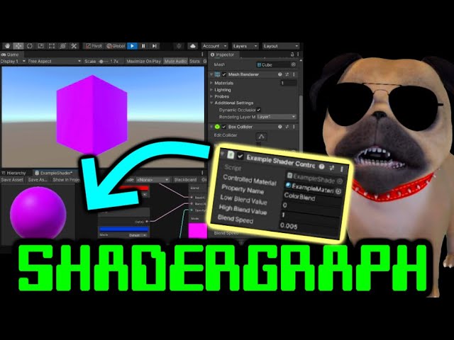
How to control shader properties by script in Unity plus a simple and quick Shader Graph tutorial.
Shader not changing? Fix it: Make sure you change the Reference!
CHAPTERS :
0:00 - Getting started
1:27 - Shader Graph - Make a new shader from scratch
4:27 - Adding an editable property to the shader
6:10 - Set the reference value SUPER IMP...
it's about changing color in a material via c# but the color change doesn't show at runtime only after I end runtime it happens in the scene view
it also happens for all objects that have that material I was trying to create a highlight shader that works per object
From this description, it sounds like the object uses a copy of the material when entering runtime, and your script is changing the original
@amber saffron I dropped in the material component from the GO but that didn't fix it
found how to fix it: private void Start() { usedMat = GetComponent<Renderer>().material; }
This should work.
Could it be that you have multiple scripts trying to edit the same material ?
The script is on the GOs
I drag and dropped in the mat file
I think that was what caused it
This is maybe the issue. If you reference the material from the assets, it will edit the asset and keep the changes while exiting play mode.
But when you do Renderer.material, a copy of the material is done on the fly at runtime to avoid changing other objects
yea I've realized
Whereas Renderer.sharedMaterial will directly return the asset, like if you referenced it.
so if I wanted to change the material itself at runtime I'd use Renderer.sharedMaterial?
IF you want to change the material and see the change affect all objects that also use this material, yes
nice thx that is good to know
Hihi, I've been struggling a while now trying to add a sparkle effect to an non-shadergraph shader I have for a personal project, and I'm wondering if someone could help me out on it T_T
Hey, I'm using a Reflection Probe node in Shadergraph, when I display the reflection onto the model it does not take into account the normal map texture, how can I do this?
Reflection probe node has its own normal input doesn't it
Hi, I got a bit stuck creating a shader. I have a .psb character imported - in photoshop I have a layer with the character clothes and another layer with the same clothes with different effects. When I put inside unity I'm assigning the material to the "main" layer clothes and I'm struggling to find the uv coordinates of the second layer of clothes. I hope that make sense
yes it does, but plugin my normal map there does not work. I think I may need to combine the object space normal with the normal map itself (?). Any idea?
Probably need to use a Transform node, to convert from Tangent space to Object
Thank you so much 🙂 that works
If it's the same set of clothes, shouldn't it be applied using the same set of uvs as the main layer?
when you import a .psb unity creates an atlas with all the layers from the photoshop file that's why the two layers of clothes have different uv coordinates
Hi all! Is this the right channel to ask for help with trying to convert a standard surf shader into a URP compatible one?
there's no easy way to do it
you have to do research into the libraries URP uses and see which functions are similar to the standard ones

GitHub
Unity Graphics - Including Scriptable Render Pipeline - GitHub - Unity-Technologies/Graphics: Unity Graphics - Including Scriptable Render Pipeline
Or remake it in shadergraph
do i have to do something with the shader graph to make it work in WEBGL Build ? i have "Invalid subscript vec","Undeclared identifier (SAMPLE_DEPTH_TEXTURE_PROJ)" & "SAMPLE_DEPTH_TEXTURE: too few arguments to a macro call.
Does anyone have any thoughts/pointers on creating the white outline grid as seen in this image: https://i.imgur.com/9nWrSUV.png - I can of course just create the texture but I'm wondering if it would be able to get procedurally generated via a shader?
Idk if this is something that involves a shader or not but dose anyone know a way to create a form of halo around a planet for an atmosphere
have you checked this? https://www.youtube.com/watch?v=DxfEbulyFcY&t=2s maybe not the most efficient option but should give some idea of the methods used
ill check it out thx
Why is it that when I select "alpha is transparency", my texture completely flips out, but only in Shader Graph?

Shadergraph node previews show the RGB data without any transparency/alpha. It's common for colours to bleed out like this in transparent areas to avoid artifacts (like the colour darkening at the edges). Might also save space in the file format, not sure.
But the final shader result will still look correct as long as it's set to Transparent type (in Graph Settings tab of Graph Inspector window) and the A channel is connected to the Alpha port of the master stack.
Hya, I'm struggling with my billboard shader for a while now. It's a lit shader (for trees), and I want the normals to rotate in such a way that the lighting represents the lighting of the 3D model it's billboarding; so when the 3d model of the tree is backlit, the billboard will be backlit, etc.
I'm having trouble with the normal rotation part. Its just not behaving as how I think it would behave
For example, the way I have it rigged now, I would think it would always rotate towards the main light, so all the trees should always be lit. But they are not.

Gives this effect

Does Anyone see where I'm going wrong with my thinking? And, how would I fix this?
Initially I thought: "if i rotate the normal the same way I'm rotating the position, it should accurately light the tree depending on the cameras position / main light" but that also gives the above example. Lighting on the trees doesnt change at all then
when moving around
I feel like maybe you need to use the Camera Direction -> Transform (world to object) result as the normal 🤔
like so?

Seems to give the same result as above, so not consistent lighting. But, the normals do seem to move based on camera rotation
it almost seems like the original rotation of the GameObject has something to do with it. If the original rotation is 0 (in this case) the billboard child objects seem to have the correct lighting when rotating the normals this way.
I meant using the output of the Transform node directly into the Normal port on the master stack. Not sure if taking the mesh Normal Vector into account is important here.
where everything goes awry in my brain is multiplying the position of the object with the constructed Vector3 direction, vs multiplying the constructed Vector3 direction with the directional normal vector
In the above though you're using World space instead of Object for the Normal Vector.
The A & B order is also important when dealing with matrix multiplication so may need to be switched. Typically it's matrix first, but might be the other way if the matrix is transposed (built using Rows vs Columns)
ahh ok thanks
Switched A&B and set normal vector to object
behaviour is nearly the same as earlier
Lighting does change upon rotating camera, but not uniformly. Setting parents objects rotation to 0 seems to get the correct lighting (based upon the main light)
Yeab B for the matrix seems to be the right way for the Position calculation like this
Did you try putting the Transform output directly into the master stack too?
Directly into the normal Master stack?
Same kind of behaviour
its hard to tell wether its Exactly the same (too many trees, to many variations)
but the lighting changes, but is not uniform. Just like multiplying the matrix out with the normal vertex (world or object)
Granted, I've never fully understood how rotation (of the billboard) translates into a position on the Vertex Master stack. But if multiplying the objects position with the constructed directional vector3 gives the desired position, wouldnt that mean that multiplying that directinoal vec3 with the normal vector (direction) is not the (direct) way to go?
Hello, I'm working with this cross-section shader that I found somewhere else. It shows only the slice of objects that is on a given plane.
I'm running into an issue where if there's any object with the same shader jutted into another, that small part where they're crossed isn't shown even when looking at a cross section of a different part of the object (so, if there's a sphere jutted into the bottom of a cube, the top crossection of it will still have that "hole" where they intersect, even if the intersection is on the bottom face)

here is an example, the white is the crossection of a cube, once the sphere intersects the cube (but not the square-crossection), it gets messed up with that hole
Does anyone know where I can find info on only building manually specified shader variants for a project?
You'd likely need to override the depth of the back-faces so it's at the cross-section plane, rather than the cube. Then the depth testing will be correct.
Can override the depth value via a fragment output with the SV_Depth semantic (or SV_DepthGreaterEqual).
Not entirely sure how to calculate the depth value off the top of my head though. I guess a ray-plane intersection with the view dir.
You probably need to be more specific about the type of shader
So i've made this wave shader that simply displaces the vertex by a sin wave of time + its x position, it works fine but the problem is when I scale the plane it's on the waves gets stretched instead of keeping their shape.
How can I adress this, I'm sure its an easy fix
Handle the displacement in world space instead. If it's a shader graph you'll then need to Transform back to object space for the Position output.
It's a shader graph
I've seen docs and examples on shader stripping where you define which shaders you don't need. I'm curious as to how to do the opposite, where all shaders are stripped except for a defined list. Sorry if it's a trivial question I'm just a little new to how shader variants are built
Conceptually I understand what you mean , but in shadergraph world i do not know how to
this is the end of my graph

and I use an absolute world position for input
Add a Transform node inbetween those, set from World to Object space
same reason of why a cube gets distorted into a rectangle if its parented to an object with a different scale
Thanks! I wound up finding a different way to do it but this would've worked too
is there a way to make vector2 properties plugged into scale and offset for textures not display as being vector4s? Not game ending they still work its just gunk in the editor\
Thanks for the tip. That is actually agonizing but that's a nicer solution.
Yeah, its jsut dumb, that a vector 2 looks like a vector 4 in the inspector 😄
agreed
I managed to recreate it so far in Shader Graph 😄 will be looking into how to get additional stuff like emissive edges in next
@vast sail @fossil cloak In Unity 2021.2+ this has been changed, and Vector2 fields now show with only X & Y boxes. Also Vector3 shows as XYZ.
😮 nice
I'm honestly torn about where I should be asking, but I'm working on a mixed reality project and I have a point cloud associated with some intensity values at each point
My goal is to visibly display regions with high intensity values as... clouds colored based on the intensity values, since the readings may not be 100% locationally accurate I wanted them to show a general area rather than a point
My initial experiments with particles didn't meet my expectations, and a shader approach fell short in my own capabilities
I feel like shader might be my best approach for efficiency on the MR hardware but I'm unsure of my approach
I ran into some articles describing ray marching for fog-like effects, but I'm not really sure what I'm doing at this point
how do I get distance from near plane from depth texture?
I tried LinearEyeDepth(SAMPLE_DEPTH_TEXTURE(_CameraDepthTexture), i.vertex.xy)
I need it to limit my raymarching distance, to make it blend with other unity objects
... I think I want to have volumetric particles
I'm not a fan of my particle system or my shader billboards clipping into the spatial mesh
how do I find the angle between two directions in degrees inside the shader graph?
I'm trying to see a plane representing where the camera can see, so I tried to set up a shader where it is invisible if it can't be seen by the camera. However it isn't seeming to do anything.

the alpha clip threshold is set to .389 because I'm pretty sure that's what it needs to be with a camera fov of 35 degrees
try using the camera node
I had the same issue yesterday
for some reason the camera node's direction worked for me
I would suggest connecting it to the base color node to debug it, makes it a bit easier to see if it's working
I... just can't Z buffer.
Trying to copy some soft particle code into my point cloud shader and the z buffer is all 0
Perhaps because I tried doing it in the geometry shader? Idk.
Gave up after a few hours of debugging.
Are you trying to asset rip?
could you maybe show how to do that?
I tried this, but it's doing the same thing.

let me open the project and see what i did exactly
wait, no i meant replace view direction with camera direction , you gotta use the normals

oh alright I'll give it a try
I closed unity a bit ago and it usually takes a couple minutes to open, but I'll let you know when it's done.
hmm, that gave an interesting effect, I'm not sure if I did it right, but it's fine. I'm guessing I can find a tutorial on it tomorrow.
Is it possible to like make shaders in normal 3d pipeline after importing shader graph
I used multiply by accident but using dot product should get you the real result
so i know invlerp gives you a fraction based on the value you input between a range but i dont understand what that means when the value is uv.y, eg: float t = InvLerp( _Value1, _Value2, uv.y );
so if its 0-1 and your value is 0.5, it gives you 50%
but what is the value for uv.y
That means that for every pixel you will potentially have a different value, depending on the uv.y value of the said pixel
hmm
It's .5. And t will also be .5 due to your example.
uv.y would be the value that you're trying to find out "how far along it is".
So a inverse lerp between color 1 and color2 for a pixel P is InvLerp(_Color1, _Color2, p) it could be .369322 of the way through the range.
That's the inverse of lerp, where you would say color3 = lerp(_Color1, _Color2, .369322) and get your color result as a little over a 3rd of the way through the gradient between the two colors.


I'm trying to scale each vertex , or triangle, of a mesh to achieve a sort of digital "appear effect". I'm struggling to make in shader graph.
all I'm achieving is uniformly scaling the object
You could proportionally move the vertices downward to fake it.
Else, you need to find a way to "roll" the vertices around the perpendicular axis of the movement.
There is so many ways to visually make an "appear effect" that I'm not sure about what you are trying to do :/
what I want to essentially do is scale each triangle/face around its center from 0 to 1
You then need to have the information of the triangle/face center.
If you were using shader code you can calculate it on the fly with geometry shader, but in shadergraph that's not possible, so you need to pre-bake this information :/
You also need a hard-edged mesh otherwise the triangles will be joined to each other
It might be something that's easier to emulate with VFX graph—with a similar-looking effect that's not the triangles explicitly
How can I make transparency T 1 of a face looking forward or backward the camera and T of zero when face is looking right or leftward the camera?

i tried this, but it works 50% of the time

i need smth like fresnel effect here
ok I thought I could make it but I'm stumped again @amber saffron ``` [maxvertexcount(21)]
void GeometryPass(triangle Varyings IN[3],inout TriangleStream<Varyings> triStream)
{
        float4 center = (IN[0].positionWSAndFogFactor + IN[1].positionWSAndFogFactor+ IN[2].positionWSAndFogFactor) / 3;

            Varyings o;
            for(int i =0; i<3;i++)
            {
               o = IN[i];
               o.positionWSAndFogFactor = (IN[i].positionWSAndFogFactor*_Scale) - center;
               triStream.Append(o);

            }


        }``` as far as I can tell this should result in at least some sort of scaling but all it does is change the way the light reacts to the object
Use View Direction and Normal Vector in the Dot Product (both in the same space)
The result will be -1 in the opposite direction so can Absolute it to get 1 in both
nvm got the math wrong should be top[i].positionWSAndFogFactor.xyz = _Scale * (top[i].positionWSAndFogFactor.xyz -center) + center;

make a sphere with more polygons
Would antialiasing post processing make it look rounder? I can imagine it could help but not sure if it would really be noticable or not
not at that scale no
when it comes to spheres the build in sphere is rather low-polly
thats what i figured
Yeah, well you are lucky spheres are easy to model 
wdym?
and this is just for a Private Proof Of concept for a 3D Sonic Collectathon Platformer
Private PoC or not, ripping assets is usually against copyright rules, and it is certainly out of subject for this channel.
If you want sonic models for a PoC, I'm pretty sure you can find some free already on the net.
i have a shader with diffuse lighting and takes light and changes based on the direction
however it doesnt change when i rotate the object itself
how can i amend this 
this is what it looks like rn

ah nevermind
had to translate my normals into worldspace
with this o.normal = UnityObjectToWorldNormal(v.normal);
Sorry thanks for the notice
I will make sure it never happens again
I don't know the actual rules for this but ive heard some very well known games that started as gamejams used sprites from old zelda games. But ofc they didn't keep it when it was going to be a commercial product.
Either way when i think about it this isnt the place for this conversation
hey again all, hit another bump in the road. I've got my colour restoration shader graph working so it restores colour as a mask passes over the objects in world space, but it only works when all objects share the same texture (left group in image). I want this to be able to work with any texture on any object, so I tried assigning the texture via script (right group) but the slider for controlling the mask becomes unique to the object instead of being applied to all objects despite the objects in the right group sharing the same material. Any ideas on how I can overcome this?

I have a confusion regarding a particular thing I want to achieve in shadergraphs
I have this group, which gives me a sort of "mask" or black and white gradient of where the object is intersecting with other objects

I want to use this as an opacity mask
to combine with this

I have the Waves&Ripples group, which outputs this texture.
I have a "FoamColor" node which is just a flat colour.
I want to combine them both, using the "Intersection Foam" output as a mask
in blender I would have simply plugged in the "Intersection Foam" into the Factor in a Mix Node
Is there an equivalent in unity
You can change the mask controlling variables as global variables, that would be shared across all the shaders
Lerp node I guess ?
Works as expected! Thank you so much
I assume this would be done via script, right? the variables are all currently exposed so I would set them as global variables using Shader.SetGlobal... I am guessing?
Yes.
Also enable "Override Property Declaration" and set to "Global"
awesome, thank you so much! 😄
im a bit confused by deferred in universal, for changing the lambert lighting model in forward all I did was modify the Lighting.hlsl but in deferred is it the StencilDeferred.shader?
One question
How can i change the surface type to make it transparent?
Cuz i saw some videos of it and it doesn’t seems to still be in the latest version
That little gear on the corner to change the surface type
Is there another way to change it?
Oh wait nvm
Found it
I need actual help with something else
So, I basically just finished doing a shader on shader graph
And
I’m trying to apply it to the model
But the thing is, that it doesn’t appears
I already converted it to material
Assigned it to the model
And it doesn’t shows up on game view
Did you save the shadergraph ?
Yes
Mais some compilation issue ?
It should show up
Maybe share some screens ? The shader, the material, the scene
Ok
Let me share it
the shader in general is basically like this

it's the ripples shader graph
i saved it as a material

and i assigned it to a copy of this street

in the game view it's like it's not even there

well, i added a transparency but even without transparency it doesn't loads
Is there a way to change the lighting model of a shader graph without remaking it as an unlit shader?
how do I make a color tint on a texture with shader graph? I've tried multiplay but that won't let me change the intesity on 3D objects like it does with sprites: https://www.youtube.com/watch?v=93jnsgD-8Wo I'm guessing it's because it is color 3 and not 4.

✅ Get the Project files and Utilities at https://unitycodemonkey.com/video.php?v=93jnsgD-8Wo
Let's make a cool Sprite Tint using Shader Graph. This is excellent for Heal and Damage effects.
Check out the entire Shader Graph Tutorials Playlist
https://www.youtube.com/playlist?list=PLzDRvYVwl53tpvp6CP6e-Mrl6dmxs9uhx
If you have any questions pos...
Meh, no easy to understand what is happening :/
But if the shadergraph is properly saved and compiled, assigned to the material that is itself assigned to the mesh, it should work.
Double check if there is no compilation error in the console, and that all the settings have the proper values on the material.
No
Ok
That's the short answer, in HDRP however the lit mode has different lighting models, but still, custom lighting = unlit
thanks
Unless you feel adventurous and want to implement an additional target for shadergraph.
I'm using urp
Managed to get it to work with blend and opacity
sorry Remy, it doesn't seem to be working as intended. after updating the script and trying to adjust the the sphere mask from the script's slider, the mask disappears entirely. I tried turning off the "Exposed" element for the variables I want to have the global control over but it doesn't seem to change the result. I've double checked the reference names in the script and they are exact matches. could it be the way I've set up the script that's causing this problem?

Could it be that you are sending the mask position in the wrong coordinate space ?
Its currently sending it in world space, I can try changing it to see if anything changes
Would space should be the good way to do it.
hmm not seeing any changes
Let me try it out quickly, to check that I didn't say nonsense 🤔
incidentally, should I be seeing the slider from the shader graph update to match the slider value from my script if it was working correctly?

if I should be able to see it update, then its likely that I messed up my code 😅
So, property need to be hidden, but it works
Anyone know of a shader to hide a water mesh inside of a boat ?
I've tried this but it doesnt do what I want and just acts odd
https://www.youtube.com/watch?v=z2uFaBoYhaY

How to Use Depth Mask to Hide Water in Boats in Unity
1:06 to skip Intro
5:14 to jump to Blender Instructions
Have you been trying to figure out how to put your boats in the water, but not let the water seep in? Then this tutorial is for you!
Here is the Unity Wiki on the depth mask:
http://wiki.unity3d.com/index.php/DepthMask
Last I checked...
Search for stencil masking
IIRC, the boat in the open source chop chop project does it : https://github.com/UnityTechnologies/open-project-1?utm_source=YouTube&utm_medium=social&utm_campaign=evangelism_global_generalpromo_2020-09-21_open-projects-01-repository

GitHub
Unity Open Project #1: Chop Chop. Contribute to UnityTechnologies/open-project-1 development by creating an account on GitHub.
@elfin mesa Did you disable "exposed" on the global property ?
I did yeah, but no success
is it alright if I share the script? just to be sure I definitely didn't forget to do something
Go on
this is it, did I stupidly forget anything?

Is it expected that you don't update the values in the update loop ?
You could just do Shader.SetGlobalVector("xxx", transform.position); (and not local position, if you want to be sure to have world space positions)
ah, I thought I was updating the values in the update loop 🤦♂️ so they aren't actually updating at all?
You are updating the values in the shader from the variables that you did set at start, but your are not updating the c# variables values 🙂
You've initialized the variables in the start function, but don't update them.
ohh, I thought by having Shader.SetGlobal... in the Update() it would in fact be updating these variables 😅
Nope, not related
also thanks for this tip!
So, it's working now ? 🙂
I apologise for the incoming basic programming question, but since I've muddled myself up thinking that I was updating it correctly, how should I be writing out the code? 😓
I'd come across a couple examples online that had done it this way so thought I was on the right path
Well, you did it correctly, taking your code you only need to add sphereCentre = transform.position; at the beginning of the update loop, and it should work (typo in the variable name btw I think 🙂 )
This will update the variable with the current position of the object before sending it to the shader the lines after.
You only need to do this IF you want to use the position of the object as center of the mask, but if you just want to use the variable itself, you should see it update directly if you change the value in the inspector
ohh I see, okay that's good to hear the code wasn't too far off from being on the money!
thinking about it, I probably wouldn't want to keep this since it will position the mask in the center of all objects that use this material, which would mean it does not look like the effect is originating from a single point and passing over objects as the radius increases 🤔
If you are using the position in world space in the shader, and transform.position in the script, the mask effect should be world positioned
I'm a dumb dumb, I was still thinking of transform.position as localPosition 🤦♂️
sad news unfortunately, it still does not appear to be applying the mask despite everything
Should look like this : https://i.gyazo.com/6cb8bd40bf3455c198ffdc1f2abdf6fb.gif

Here's the shadergraph :

And the code :
using System.Collections;
using System.Collections.Generic;
using UnityEngine;

[ExecuteAlways]
public class GlobalShaderPropertySetter : MonoBehaviour
{
    private void Update()
    {
        Shader.SetGlobalVector("_Pos", new Vector4(transform.position.x, transform.position.y, transform.position.z, transform.lossyScale.x*0.5f));
    }
}
huh, perhaps my shader graph is incorrect 😵💫 this is my shader graph:

the texture that I've applied was just added for some clarity, its still set correctly via script
Should be good
Once again, check that the 3 properties in the graph for the sphere mask are set to global and not exposed
I believe they are all set up correctly


Yes...
And it's still not working ? 🤔
sorry for taking up your time Remy, I'm just so stumped by this
from what I can see, it still does not work 😣
Shouuuuld 🤔
Do you mind moving into pm to avoid continuing to take all the space here, and maybe do a screen share ?
yeah, of course!
I messed around with some example projects but havn't been able to reproduce it.
On the one you sent I cant seem to open the zip and I wouldn't understand the graph anyways if I had to guess (cant even find the one that does the water hiding thing)
Any more straightforward stuff ? Stencils are confusing
I just need a shader that if a pixel renders a stencil then the pixels under it will not render another particular set of object
what object do i pass to compute shader so on the other end it recieves as texture3D?
pls ping me if you answer
if I need to make some animated grass in a pinch, what options should I consider? I'm dizzied by the number of them
And sometimes the information seems conflicting
In a pinch ? Go for the tried and tested vertex weight paint on a simple mesh and move the gras based on that
Isnt there some free ones on the asset store or built in to unity?
You'll find a ton of them using geometry shaders. Geometry shader stages are SLOOOOOOW. My 2 cents is to avoid geometry shader versions, and go with vertex versions. Lemme see if I can find a link.
Maybe you can adapt this to whatever pipeline you're using:
http://protasovnn.com/2021/02/01/Unity-urp-hlsl-grass-shader/
Nikolay Protasov
Unity tutorial how to create HLSL URP shader for generating grass
Making the grass itself isn't a problem but I'll probably inevitably have to pick some way to optimize it (batching, instancing, whatnot), and that'll dictate how the grass can be made and scattered, more or less
Thanks for the resource!
Hey, i am using a URP Unlit Shader graph here, but i cant get any image to fit the geometry, is their a way to no matter what picture i have on the card face, fit within the geometry ? or without telling me point me in the right direction ?


Do your Texture have the same size / aspect ratio as the Mesh?
anyoen have any idea how to make a billboard shader that only rotates on the y axis?
i've been looking for one and the ones i find online all show up invisible
You can do it via script
i'm having a really big problem can u help me
Just post your Problem ^^
so every time i try to make a new project it gives me an erro and tells me to check the logs
like so

hmm, if i have a lot of things using it would that affect performance a lot? or would it be about the same
maybe a little less performant, but not that much i think
any fix for the preview in shader graph not showing anything at all?
it's broken for me on most shaders
okay it seems to only be broken when i change them material to "lit"
and decal*
I managed to do custom lighting for lit shader graph, I just cloned lighting.hlsl, edited the lighting functions then changed all references in the code generated by shader graph
The preview in Shadergraph is crap most times.. 😄
Anyone know of any water shaders that look similar to the water in Pikmin?
Or does anyone have any ideas on how to replicate it?
looks like a noise with a Fresnell
thanks
Overlapping scrolling normal maps on a mesh reflecting a cubemap or a matcap
UV map and/or vertex color flow direction, and looks like vertex color transparency on the shore edges too
thanks so much dawg, this is spot on
I think games from that era used matcaps for almost all reflections, and meshes with vertex colors and repeating UVs very extensively to avoid storing a lot of textures or doing expensive shader math
yeah the way the light reflections work on the water feels very "static" if that makes any sense
hey again all, I'm trying to figure out the best way to create an emissive coloured edge around the rim of my sphere mask - something similar to the attached image. I've come across a couple examples online written as standard surf shaders that use clip() to achieve this effect, what would be the right way of rewriting this function in shader graph? I couldn't find a node that performs this calculation so I assume I need a few nodes to perform this calculation, or if there's a simpler way to get a glowing rim then I am open to suggestions! 🙂

hello i am a sttudent in a coding school and for my project i want to make a simple one level game with ray tracing i have the system reqirment but i dont know how to do it does anyone know a tutoriel or anythung elese
and i think i need to go to #archived-hdrp
You can find many tutorials for shader graph of this effect seraching by the name "intersection"
Though you may need to invert the logic in some way if you specifically want the glow rim to happen on the ground rather than the sphere's surface
great, I'll start looking into it - thank you!
could someone confirm for me if the Fraction node in shader graph is the same as the frac() function in CG?
it is
you can always check the Generated Code Example: https://docs.unity3d.com/Packages/com.unity.shadergraph@6.9/manual/Fraction-Node.html
perfect, thank you!
what kind of bending you mean?
I don't think single matrix alone can do that. afaik matrices can only represent linear transformations (translate, rotate, scale, stretch, combination of those etc.)
matrices can do rotations but you can't have matrix that rotates differenty on different parts of the model, rotation matrix would rotate all the vertices same way (unless you change the matrix per vertex according to y position for example)
is there a way to do "bindless textures" on gpu compute shaders in unity?
this is very simple i imagine, how do i scroll this noise map?

I basically just want to make a slightly oscillating lava shader
by changing the uv value?
that just makes it a solid colour, and flashing immensely fast
maybe connect these? 😅

of course...
did I suggest touching this connection? 🤔

ah ok, I meant this one which you didn't do anything to

Question: Does doing something like this (stopping animations at a certain distance from the screen) help with performance, or is this method useless?

Im pretty sure that is useless. Branch node transforms into ternary operator which as far as I know never generates branches (in hlsl. dont take my words as a final truth, there seems to be some contradictions between sources) meaning it will always evaluate both sides and just discard the result of other one using some simple math trick
aww dang :/
i wanna have animated foliage but i would like the far away ones to choose performance over quality
idk if swapping materials would be the right path for that or something else
Hey folks, I'm getting an issue which I assume is shader related but not sure as the logs aren't reporting any errors. In a nutshell it only happens in Standalone PC builds, not in the editor, and only after the game has been running for around 30mins or more. And it only happens when a scene has just been loaded (either when exit a scene and enter a new one, or re-load the same scene)
The screenshots here show what it should look like compared to what it looks like when it glitches out
I suspect it's a problem with an Amplify shader or maybe some custom post processing effects, but because the issue is hard to recreate I just want to get some opinions before I pour too many hours into it
I'm using Unity 2019 SRP, and OSX 10.15


Hey y'all. Basically, I'm working on a system to procedurally generate planet models using Shader Graph. The issue is that whatever I'm using to generate continents is looking absolutely abysmal, basically. I'd like some advice on how I could get noise with higher "roughness" without using the current system which gives me super messed up continents. Thank you!


maybe use two passes of noise.
One very crude pass for making continents.
A second pass for adding roughness
oh wait are you doing that already? 😛
Yep! Was about to say lol.
your bottom noise looks very fuzzy still though
I'd do some hard cutoff to make clear continents before applying the roughness patch to it
Just tried it! Dude that worked like a charm, TYSM
Do I need also make custom shader for my materials and "render" fog on top of them to avoid things like this when sunrise?

Right now fog is enabled in lighting settings in URP.
You would swap the foliage meshes over distance using LOD component or a similar system to a variant that has less polygons / different material with a cheaper shader
I believe a common way is to reduce grass height over distance to zero and cull the mesh at that distance entirely, among other optimizations
If you have to ADD logic to calc distance and branch for a particular frame of animation, you're ADDING cycles to the total time it takes. That might not be too bad in a vertex shader stage, but it's still MORE time than it takes to just calc the frame.
As you say, and as others have said, swapping out the material for one with NO calcs might make it faster. But now you have to analyze everything per-frame to decide if you want to swap it out or not, and that will cause time delays. Or maybe you can "just" do it based on camera position (with a distance calc) and not screen position.
It's a catch 22.
Here's how it works. If all gpu cores in a thread group take the same branch of an if-else, you can skip the other not-used one. But if even one core of the, say, 64 cores in the wave takes the other branch, they all take it but most are masked off. So you'd incur the cost of both sides of a branch.
So if you think about it like ^^, you'll find that the trees in the distance might all take the "off" branch, and the ones close will all take the "on" branch, and then there will be some in the middle that are processing things that could be in middle ground and take a two-way hit. But the only way to tell if you're gaining anything at all is to actually run some benchmarks and find out, for your calcs in your scene, how it all shakes out each way.
What is the correct way to get the actual time (in c# script) value used in shader graphs Time node. neither Shader.GetGlobalVector("_Time").y nor Time.timeSinceLevelLoad seems to be it
Did you try Unity's Time class? IDK for sure but I'd assume they're synced with what they past to the shader variables.
So Time.deltaTime and such.

I told someone to use Time.time as an equivalent of node time, and they said it worked so I guess it does
The best way is to just make your own time variable
That works for about 30 seconds, but then Time.time and the Node Time seem to be falling out of sync with each other
sloowly..
Strange but not unexpected
Cyan's suggestion is the way to go then
Then do what Cyan said and pass your own so you know what it is and both sides agree. But you'll still get it from the Time class.
I see... so basically pass Time.time into the shader, and in c# both
so they are both on the same page
P.S. I have no idea how shader-time gets out of sync in that node, since shaders don't retain values between frames unless you work at it really really hard.
I don't think this is the actual issue because the difference in times is so small but still I'm wondering why _Time doesn't get reseted when loading a scene even though the docs says that _Time is:
Time since level load (t/20, t, t2, t3), use to animate things inside the shaders
is it possible to morph from one ·3D model to another 3D model through a shader? cuz for now the only good solution I found is done with mesh scripting
depends what kind of model it is
you can't really change the vertex count or anything like that but you can move the vertices around in a way you want
Are you testing this in edit mode? Maybe it only happens in play mode, or only in builds? Or the docs are just wrong 🤷
that did seem to happen in build too
yeaaah for now the way I found is with two or more 3D models that have the same vertex count
ray marching could do that very easily but in that case youd need to define both models as a mathematical distance function and not 3d mesh with vertices etc.
wait really?
u talking to me? XD
It's theoretically possible, but likely impractical. With a shader, AS A GENERALIZATION, you get ONE mesh that you're processing...not two meshes.
However, you can pull a lot of fancy tricks and a special setup where the two meshes have the same number of verticies. So you could be processing some "base" mesh, and have a buffer for a 2nd mesh's vertex data (maybe a structured buffer), and use SV_VertexID info and then lerp between the two verts for MeshA and MeshB.
But you're biting off a lot if you even have to ask the question, you might want to be careful of what you're getting into.
okay okay, I mean I have a way of doing it already, I wanted to check if it was more powerful though a shader
yes

oookay so raymarching might be a way
if the mesh is not super complex, implementing that in a shader may not be worth the effort (and even then using compute shader would be better than vertex/fragment shader)
Assuming it's even possible to represent the mesh with an SDF...raymarching is also pretty slow over all.
that's also true
the meshes are usually a bit complex and I'm supposed to do it with meshes they give me, not meshes I edit (if possible), so I'm looking for ways to morph models with a different number of vertices
which is of course (from what I've found for now IN UNITY) not feasible
but even if it's not feasible I have to explain it in my project
I know I know hahaha
no worries
just checking, it is also interesting
Let's go back to what @dim yoke is saying then.
So you can morph a cube with N verts into a sphere really really easily. Because a sphere calc is just a distance from center, regardless of how many verts there are.
You don't even need ray marching.
But if you want complex meshes and to morph, you'd have to pass in one model, and then the other model...and somehow calc for each vertex of Mesh1 how close it is to the nearest vert AFTER the morph is complete, and then decide how far to go between Mesh1 (start) and mesh2(final) and lerp that distance.
So you'd have to iterate through Mesh2's data, projecting Mesh1's vert onto it.
I think I use something similar in the script I shared before
but yeah, same vertex number tho
I will send screenshots of the code if u guys are curious but feel free to send me to another channel if I've gone off topic already
This kind of thing is done with blendshapes, but it's not for the faint of heart. Might be worth the research to figure out how that's done for things like complex facial expressions.
@steady pike If the meshes have the same topology and you know how to use modeling software, shape keys would be a very simple way to go about it, I think
Yeah, push it all back onto the modelers. 😉
hey, I implemented this
it still goes off sync..
using a float instead of the Time node

and incrementing it in script by 0.001f
in void Update(){}
"Incrementing it" ??????
that won't be in sync with Time.whatever.
Set it from Time.delta time, or or some other time variable.
Im not using Time.whatever at all
That's your problem. How are you determining it is "out of sync"? out of sync with what?
WaveTimer += 0.005f;
rend.material.SetFloat("_Wave_Timer", WaveTimer);
I manage my own time variable
then pass that into the shader to be used in place of the Time Node
so that
So how is it "out of sync"? It's SET.
it's a float passed.
The shader and the CPU are using the same floating point value.
I use the same time variable below in the C# script
    Vector3 GetPosition(Vector2 posXZ)
    {
        float waveSpeed = rend.material.GetFloat("_Wave_Speed");
        float turbulence = rend.material.GetFloat("_Turbulence");

        float time = WaveTimer * waveSpeed; /*Time.timeSinceLevelLoad //Shader.GetGlobalVector("_Time").y*/
        Vector2 addNode = posXZ + Vector2.one * time;
        float gradientNode = Unity_GradientNoise_float(addNode, turbulence);
        Vector3 multiplyNode = new Vector3(0f, gradientNode, 0f);
        Vector3 objectSpacePosition = plane.InverseTransformPoint(new Vector3(posXZ.x, 0f, posXZ.y));
        objectSpacePosition.y = 0f;
        Vector3 finalAddNode = multiplyNode + objectSpacePosition;
        return plane.TransformPoint(finalAddNode);
    }
These calculations that I do in
This is basically my shader just converted into C#
im trying to replicate the exact same stuff my ShaderGraph does in C# instead
Maybe there is something else in the calculation that is different

That is what i'm getting at.. but its all just straightforward add and multiply's.. i can't imagine them being too different..
im not sure though
Probably in the Gradient Noise calc then
Must be. And IIRC some shader calcs ....cheat in the actual code.
Also be aware that you don't want fixed or any lower precision calcs, you want full floats.
could be.. I have no idea how to go about fixing this dang thing
When I look at generated code of the shadergraph
this is what it returns
    Vector2 unity_gradientNoise_dir(Vector2 p)
    {
        p = new Vector2(p.x % 289, p.y % 289);
        float x = (34 * p.x + 1) * p.x % 289 + p.y;
        x = (34 * x + 1) * x % 289;
        x = ((x / 41) % 1f) * 2 - 1;
        return (new Vector2(x - Mathf.Floor(x + 0.5f), Mathf.Abs(x) - 0.5f)).normalized;
    }

    float unity_gradientNoise(Vector2 p)
    {
        Vector2 ip = floor(p);
        Vector2 fp = frac(p);
        float d00 = Vector2.Dot(unity_gradientNoise_dir(ip), fp);
        float d01 = Vector2.Dot(unity_gradientNoise_dir(ip + new Vector2(0, 1)), fp - new Vector2(0, 1));
        float d10 = Vector2.Dot(unity_gradientNoise_dir(ip + new Vector2(1, 0)), fp - new Vector2(1, 0));
        float d11 = Vector2.Dot(unity_gradientNoise_dir(ip + new Vector2(1, 1)), fp - new Vector2(1, 1));
        fp = fp * fp * fp * (fp * (fp * 6 - Vector2.one * 15) + Vector2.one * 10);

        //Vector2 fp_1 = new Vector2((fp.x * 6) - 15, (fp.y * 6) - 15);
        //Vector2 fp_2 = new Vector2((fp_1.x * fp.x) + 10, (fp_1.y * fp.y) + 10); //Print and check output for Vec2 * Vec2
        //fp = fp * fp * fp * fp_2;

        return Mathf.Lerp(Mathf.Lerp(d00, d01, fp.y), Mathf.Lerp(d10, d11, fp.y), fp.x);
    }
This is converted to C# by AleksiH
the original was in HLSL, slightly different in terms of syntax
I certainly will, thanks for the explaining from before though 🙂
isn't this a Blender thing ?
Blender calls them shape keys, unity calls them blend shapes, other modeling programs are capable of that as well
I get the terms mixed up often
could some explain what these comments mean exactly?
this is in hlsl
float2 Unity_GradientNoise_Dir_float(float2 p)
{
    // Permutation and hashing used in webgl-nosie goo.gl/pX7HtC
    p = p % 289;
    // need full precision, otherwise half overflows when p > 1
    float x = float(34 * p.x + 1) * p.x % 289 + p.y;
    x = (34 * x + 1) * x % 289;
    x = frac(x / 41) * 2 - 1;
    return normalize(float2(x - floor(x + 0.5), abs(x) - 0.5));
}
also could you explain what you mean by fixed/lower precision calcs?
I'm just saying that in the shader, make sure you use floats (float, float2, float4, etc) and not fixed types (fixed, fixed2...) or half types (half, half2...) . Looks like you are using floats. 🙂 Your comment agrees ("need full precision").
back again with more questions! so I successfully got my custom node to perform the same behaviour as the clip() function in CG, but it discards all pixels from the input which have a value < 0 (second image) which I don't want. I've edited the custom node so that it instead turns all pixels into greyscale but it applies the emission colour on top of them. I want to be able to set the intensity of the Emission Colour property to -10 so that it no longer shows on top of the pixels which have an input value of < 0.
I think I found the correct code on the Unity docs and online, and found the values I need to set the emission intensity to -10, but it doesn't appear to have any effect. Can anyone tell what I need to change to correctly change the intensity?


Hi all, quick question I can't seem to answer on Google - possibly just bad choice of words.
If I'm using Shader Graph, do I have to manually re-implement all the base functionality of the specific pre-provided shaders? e.g. if I just want to "extend" standard HDRP Lit do I basically have to recreate the whole shader myself in a graph and then add my extra functionality?
The empy graph is the base lit or unlit shader. You have to hook in the inputs tonit
Anything you do is extra functionality
So I simply have to expose a load of properties and hook them up to the right things?
I think that's the way
Would be nice to have a graph with properties and texture samplers all set up for quick modification
But I guess you can make one yourself and use that as a base
Maybe this is the wrong section, I will post it in #✨┃vfx-and-particles, sorry.
hey guys, is there either a c# or shader line along the lines of #if SINGLE_PASS_INSTANCED_RENDERING
Hi folks, I needed a shader that adds a pixel outline to sprites with a thickness of one pixel. I was able to find a shader suitable for me, but above all I would like the outlines between the sprites to be combined and not displayed at the intersection points. I rewrote the shader into two passes by dividing the outline and sprite display, but I don't get to display the outline behind everything at all. Now everything works, but only when the sprites are on the same coordinate on the Z axis
I attached the shader itself to the message and an example of how the shader works now (left side) and what I need (right side)

Hey, I want to make it so a specific mesh isnt rendered behind another specific transparent mesh
hey,
I don't know much about shaders.
I'm using this asset https://assetstore.unity.com/packages/vfx/shaders/character-shader-pack-2-0-urp-lwrp-199155 on an android project.
it says it is compatible with Universal RP which I have installed on the project, but when I tried to apply one of the shaders on the default robot_prefab, it looked like this
I think I need to setup something for the URP to work!, could someone help?


Add depth to your next project with Character Shader Pack 2.0 (URP & LWRP) from Easy Game Studio. Find this & more VFX Shaders on the Unity Asset Store.
@pale python Are you sure your URP is set up all the way? There are some steps to it
no i'm not, i dont know how to set it up, could you help me, please?
Instructions in pinned messages of #archived-urp
Thanks for the detailed answers!!
Yeah I'll run some tests and see how it improves! My levels are mostly linear, so if the camera culling makes it so the unseen trees don't have their shaders processed, then it should be okay without much optimization
Hey, I want to make it so a specific mesh isnt rendered behind another specific transparent mesh
Stancel buffer are often used for such effects
can someone tell me what does CameraClipping thingy in ShaderGraphs do? For the love of god I can't find anything about it and I fail to understand what exactly it does by experimenting.

It's not a node that I'm familiar with, so it's probably a Sub Graph. Double-clicking it should open it's graph which might give some hints to what it does.
Holy hell, you're right! Thank you very much!
yes but idk why
I looked into it to no avail
trying to create a particle material that is additive, but the black channel isn't transparent

I tried putting the result into the alpha channel which makes the black part transparent in preview mode but when I try to change the color in the particle system it has no effect. it remains white and very dim
quick noobie question in Shader Graph
If I want to change the value of a node via script, how should I reference that node? ( by it's Name:string , or by its Reference:string ) ?
you mean in the editor the actual node or just a shader property at runtime ?
Not sure what you meant but I have this node for example, I want change its value from 0 to 1 on runtime via a script, how can i do that ?

Thank you!