#archived-shaders
1 messages · Page 202 of 1
Interesting. How would I go about doing that?
Who are you asking 👀
Would it be the same approach I'm doing now but using just setting vertex position to NaN where I have blue in my test scene?
Idk, I'm late to the grass talk.
You're basically asking to check if it is "under" something in your mask map. And IDK if you can go by some origin like object-space vertex 0,0,0. If so, you can check the mask, and then decide on a binary basis if it is clipped or not.
And I haven't decoded his shader. Hate graphs. But.
you could set the output clips space position of each vertex to be something that gets clipped.
Maybe with a conditional and a ternary operator.
@grand jolt it probably would be easier to just ask: how do you make a shader for leaves?
my idea of simply slapping the texture with a sample 2d array and connecting it to the alpha clip threshold has failed and the result is just a grey blob? anyway, not sure what i can still add or remove, or what im actually doing tbh

Ugh, let me load up the sad clone of Amplify.
Gonna be URP, I ain't sitting here for 10 minutes opening my old HDRP project 😄
ik the feeling, if i can translate it to hdrp then idm
i guess some things will be differnt
i just need the leaves to look like leaves, then figure out how to do a water and waterfall. thankfully i found some tutorials on youtube for those, and got pretty close to a decent result
Yeah that sounds right. God this is a brain breaker hahaha.
I'm unclear on if you have individual blade meshes or you said quads?
They are built using quads but all of the grass on one "terrain chunk" is combined into one mesh
not actual Unity terrain, a mesh representing my terrain
Oy. It looks 2D from the pic you posted. So I'm getting confused.
So the "mesh" is a quad, or a bunch of triangles. Ortho mode camera.
I'm asking because IDK how you isolate a "blade" in a camera-facing quad with lots of grass on it.
Since the verts are the vers of the quad, not the blades.
Yeah the grass is a series of quads that all face forward in a 3D environment but after they are created they are combined together. Our camera is static so there is no need to rotate them.
If you change the material so there are no textures, it looks like a bunch of cards following the surface and facing in one direction
It's a toon shader so the lighting gets flattened, but they look like this when the texture is off

See the shader you're converting uses individual blade-meshes. So it can figure things out. Yeah.
OK, so maybe you can figure out the worldspace position of the verts along the bottom, but you won't be able to isolate a diagonal piece of grass in the texture on the billboard.
Which would be a problem.
@stable lake smth like this maybe

thanks, ill give it a go
I think it's okay if it roughly follows the shape of the grass using the top of the quad, it doesn't need to be completely along the "point" of the blade in the texture
You need the bottom of the quad, mapped to your map. As far as the "top" goes, IDK what to tell you...that's the problem.
You're using an individual-mesh technique on a billboard quad.
The best you can do is clip all the Y (vertical) parts from the occluded part on up to the top of the quad.
@grand jolt finally, that worked. you saved me a lot of headaches man, thanks for taking the time of day to help me out. bless u!!

Next step would be writing em by hand with fast fake SSS 😄
i started learning c# a month ago, my skills aint gonna cut it lmao
maybe in a few years
I think that would be a good enough solution @meager pelican, I think I need to break and come back to it. This is a brutal problem to solve. Thanks for your help.
Cool, just remember that if you're clipping PIXELS then you have to pass that to the frag() stage and clip it there. You can't just clip the whole mesh. Then you may get into some (hopefully minor) mobile issues on tile-based systems.
@willow pike
Yes it would definitely need to be clipping pixels rather than the whole mesh. I'll give it another go later and post any progress. Let me know if you have any other ideas, feel like I just fried my brain hahaha. There has to be some simpler solution 🤔
I'm remaining optimistic. 🙂
The most reasonable solution would be just automatically generating grass detail splatmap that doesn't have the grass there.
That sounds like a good idea, would it be able to update the grass when we add in new objects to the terrain surface or move existing ones? We want to be able to work in the editor and quickly see the impact of changing scene compositions without having to finesse grass that ends up stabbing through objects and looking bad.
Ideally you would have a bake button in your editor tool.
Are you using the terrain system?
You could also flip the concepts upside down and do what Far Cry V did.
Where you paint biomes.
And place the buildings.
Then press bake and it places everything accordingly.
It’s a custom system using subdivided planes that we can change the elevation of. (Think Roller Coaster Tycoon or Parkitect) but we want lush toony BotW style grass in most biomes.
The important part is that we have a way to quickly change the detailing over areas and move things around and have it look good without getting hung up on correcting the grass each time we add features or move stuff.
Seeing grass stabbing through rocks and tree trunks all over is giving me an aneurism lol and cleaning them takes too much time
how to fix this shaders problem?

that purple thing is a plate
dont worry about it
try upgrading your materials to hdrp materials
hmm okay how tho?
edit > render pipeline > hdrp > upgrade from builtin pipeline > update materials

you can do it 1 by 1 or do as i said, that will automatically update all materials for you
i have that renderpipe thign but i dont have the HD render ... @stable lake
so?
well even if its URP should be the same process
So, I'm new to shader programing
Are there any good tutorial series that you guys recommend?
(Not new to unity, just shader programing)
If you’re doing Shader Graph I’d suggest looking at Cyan’s site. He does really great shader graph break downs and explanations. I don’t know about shader code though.
Do you have any examples or resources to point me to? Haven’t used splats before. I didn’t play Far Cry but would be curious to see how that was implemented if there’s anything out there.
Currently I’m building the world using 128x128 “terrain units”. They’re just pro builder planes with subdivisions that we can change the heights off. But they have a grass spawned script that spawns grass quads at vertices along the surface of the “terrain unit”
So you create a mesh renderer per grass blade?
They have some random offset and randomization in the uvs to create different looking more natura grasses
But after they are spawned on the surface of that 128x128 terrain chunk they are combined into a single mesh
Helps performance a ton
So one 128x128 chunk has a single childed 128x128 game object that contains all of the blades for that section of ground
yes your guess sounds reasonable. I am checking the precision along with making a test build to play with a few variables in the shader.
The RT format doesnt seem to be the issue, its definitely some shader functionality that works different on the mobile architecture
@willow pike what I suspect modern terrains do is they dispatch a compute shader that samples the grass splatmap for the current streamed in area and build the vertex buffer with all the grass meshes in it. Then they queue up an indirect render call that uses that vertex buffer to draw it in 1 drawcall.
Anyway. If your grass is gameobject based you can put like a grass blocker collider on your houses or something and raycast to check if the grass is blocked. Or use a top down view acceleration structure that has all available areas where grass can go cached.
Idk if you place the grass in the editor or not.
To be clear I haven't done any of it. I just saw what some indie/AAA did.
Gotcha! It is Game object based but since a whole field is a single mesh I wouldn’t want to turn off that whole field. The grass is created in editor. Maybe before the meshes are merged I can do a check against a splat or temp camera tied to that section of the terrain.
Some ideas: if you go with the grid of raycasts in the editor for removing grass, your tool can cache the last touched terrain piece so you can press bake last instead of bake all.
Remove those blocked blade pieces and then merge the remaining
Yeah I would need something like that so it didn’t take five minutes to build every time I move something
I might end up using smaller sections of merged grass quads so only those small piece need to be rebuilt. But having a single quad game object for each grass piece got way too performance heavy in game.
You can go a step further and stop using gameobjects for grass completely.
Then you would save grass positions into a scriptable and later use it with Graphics.DrawMeshInstanced.
It would be less editor fuckery possibly.
Interesting. Sounds like it would be nifty if I can figure it out!
And the grass would still show in the editor too? That’s important for us. I’ve seen a lot of nice grass tools that only spawn in grass at run time but we want to be able to see it as it will appear in game.
Hey guys, say I wanted to shade the interior of a shape completely white, i.e when you enter the shape, the parts of the screen inside the shape should be shaded completely white, how could I acheive this?

@willow pike yes. You would need to hook into the renderer.
In URP you can do that using the .preRender event on the pipeline or by writing a custom Renderer Feature.
Hey, hope everyone's doing well. I had a question relating to CustomRenderTextures. I'm attempting to write a shader for a CustomRenderTexture attached to a RawImage component on a UI GameObject. The only thing I'm trying to do in the shader is render an inputted Texture as-is to the RawImage. But for some reason nothing is being rendered to the RawImage.
I probably wouldn't be trying to use a CustomRenderTexture for this, but the project I'm working on uses one. If anyone has any tips or advice on this, that would be awesome. Thank you!
Shader "Custom/DrawTexture"
{
    Properties {
        _SnapshotTex ("Snapshot Texture", 2D) = "white" {}
    }

    SubShader {

        Lighting Off
        Blend One Zero

        Pass {

            CGPROGRAM

            #include "UnityCustomRenderTexture.cginc"
            #pragma vertex CustomRenderTextureVertexShader
            #pragma fragment frag

            sampler2D _SnapshotTex;

            float4 frag (v2f_customrendertexture inputFrag) : COLOR
            {
                return tex2D(_SnapshotTex, inputFrag.globalTexcoord.xy);
            }

            ENDCG
        }
    }
}
@onyx jungleOK, you sound like you're wanting volumetrics. And it's more than what you might have expected at first. You want to give/render actual 3D volumes rather than "shells" like you do with meshes?
Or perhaps you "just" want to slice the cube?
Anyway, https://www.alanzucconi.com/2016/07/01/volumetric-rendering/

Learn how you can use Volumetric Rendering shaders to improve your Unity games. Tutorial and code provided.
yea exactly, volumetrics is something I had anticipated, I would like to just render the whole interior of my object white.
This can be done with things like light and fog too.
Also hey again, thanks for your help with the sand 🙂

Imagine this scenario
where the camera is clipping inbetween the object
🙂
I essentially want to render the interior white here
Also it would need to work for an irregular shape
not just a perfect sphere/square
any pointers would be great
I did try tinkering with screen effect shaders, but they seemed to effect the whole screen, I needed it to be per object
Yeah, it's a whole thing. Often/usually done with ray-marching. It's almost a discipline in and of itself. It is for things like medical imaging. You're going to have to bite the bullet in research if you want "pretty" results.
See that link above and start googling first to familiarize yourself with volumetrics.
I wish (sincerely wish) it was a 1 hour answer. But it isn't.
But maybe you can cheat somehow. Like think minecraft instead and do voxels and small objects.
how do you mean
how could voxels help render the interioir of an object white?
or were you just thinking of a comparison
Well, just like real objects are volumetric and are composed of atoms, your objects could be composed of many small cubes. Fairly small. With little effort and no ray-casting.
But it would look blocky like minecraft.
yea no, id rather do the research properly to get a satisfactory result
Like procedurally generating it from voxels
OK
All depends on your needs and what you're after for the effect.
Let me ask you what you mean by "white"?
In other words, if you used 2 sided geometry, and you had interior triangles mapped to a white texture, but it is hollow inside, does that work?
no not really, because I already have a volumetric effect going on within the object, currently utilizing some scattering
so the interior is actually orange by nature
OK, so much for the easy off-top-of-head cheats. Have at it, and good luck! 🙂
Thanks 🙂 Ill let you know if I find a nice solution
first stop for me is that link you sent
thanks again
ayy, so im having troubles inverting a transparent cutoff shader
basically, when an image is has an alpha above X, make that part transparent
the white circle should be transparent and letting me see through to the other side

but no matter what alpha i set the pixel to, its not transparent
the fancy visual scripting thing?
can i use clip() pixels above a certain alpha value?
i basically just need to inver the default transparent cutout shader
ack!
to that end, how do i even know my shader is transparent?
maybe its been working, but the background is just white
is there an easy way to do this(?) : I want to be able to add my own ambient lighting (NOT the global ambient lighting) to a material using a Lit Shadergraph. Basically I want it to behave like a lit graph sometimes and a unlit when I tell it to.
I figured it out. nm
yeah, why does setting col.a = 0; do nothing?
WAIT
I THINK I DID IT
HAA
aaand i immediately fucked up and lost it somehow
welp
@warped vigil Alpha cutoff is for opaque stuff. It's not usually run in the transparent queue. Maybe you can override that but IDK if you're using SG.
Otherwise, use transparent queue, and do the cutoff manually. To do that use the discard or clip nodes.
So if you're doing any non-zero levels of transparency.
i plan to
and im not using shader graph
col.a = 1 - col.a;
clip(col.a - _Cutoff);
inverts it how i like
but only does full transparency of not, and i would like inbetween values as well
OK. So if alpha is, say .75 and _Cutoff .5, you want that to be gone? But if alpha is .25 you want it to stay.
And for .25 do you want that 25% transparent, or 75%
the grey area should be half transparency, but clearly isnt right now

Are you rendering in the transparent queue? And what are you putting into alpha?


There's a pragma in the shader that tells Unity (and you) what queue you're in. I'm asking what queue you use. I don't care what your pics/sprites look like yet.
And you're doing traditional blending?
cant say i know quite what that means
Surface shader or vert/frag or what?
vert frag
nope
You could try adding
Blend SrcAlpha OneMinusSrcAlpha
up in the pass section, but I think that's the default.
Probably won't fix it. You'd have to post your shader.
Best to use pastebin or something to post it.
gotcha
mind you, its a pretty awful bootleg of one of my other shaders
i struggled for a bit, so i just started trying random shit
Pastebin
Pastebin.com is the number one paste tool since 2002. Pastebin is a website where you can store text online for a set period of time.
ayy
I still don't know what you want the alpha to be though, after clipping. The original or the modified somehow one?
Cools. Your render type is still cutout, and IDK if you want that. (in the tags). Will have to look that up.
its not quite perfect, but it worked well enough for what i need it to do
thank you for the help
When I look down the floor material is visible

When I look a different direction it looks darker

Anyone have this problem,?
NVM lighting was turned off
hi there, i dont know if this is the right channel for my problem. -> i use a model package from asset store, i replaced shader for all objects, the problem is, after replace the shader, the material is stretched on some surfaces. not alle on the object. maybe sometimes only one side is streched. without my shader everything looks good. any ideas?
hello, is it possible to create or use already existing shader to avoid / ignore object's Normals? I have a lot of objects that have inverted normals, and I want to use them unlit therefore i assume that there no need of normals. there is an example of viewport rendering from 3ds max that shows what want in unity. thx


I've tried 2 sided standard but half of the objects become transparent.
a 2 sided unlit material should do what you need @latent mirage
Is 2 sided mean twice more drawcalls?
No, it means more triangles rendered on screen
Do you have any kind of this shader?, I've searched 2sided everywhere: assetstore,google ,forums but found only 2sided standart shaders with is very hard in performance wise on mobile devices. 10 times worse than unlit
"More triangles to render" how much is it worse in performance wise than standart unlit?🥲
Literally the only thing to do is to create a new unlit shader and add Cull Off
Try two cases with and without that line and you can compare the performance
I think the best way to fix this is fixing the model's (inverted) normal
there are tons of it, each map ~2500-3500 objects with corrupted normals
@latent mirageTry recalcing them on import.
https://docs.unity3d.com/Manual/FBXImporter-Model.html
See the normals option (letter C)? Right now, you probably have import. Change it to recalculate. Reimport the model.

I see what you mean but it doesn't help. i think only solution is to avoid normals consideration at all


but here is what normals do

upside and down side
Well, you can make sure tangents are recalced too (it should default to recalc if normals are recalced, but check). Tangents are used in lighting.
Otherwise, you've got some major modeling problems, and should fix it there like @tacit parcel said. Otherwise you're setting yourself up for a wold of hurt.
Just my 2-cents.
3d model have problems itself, it is normals, but i supposed that here is in unity some shader like in 3ds max that don't consider normals

Hi guys 🙂 I am currently dissecting an HLSL script from a bought asset. I'm currently learning HLSL and I learned that you can use #includes in your ShaderLab shader and reference other HLSL scripts to use those functions. Now in the script I am currently looking at there is this part:
#define CUSTOM_LIGHTING_INCLUDED

void MainLight_float(float3 WorldPos, out float3 Direction, out float3 Color, out float DistanceAtten, out float ShadowAtten)
{
#ifdef SHADERGRAPH_PREVIEW
    Direction = float3(0.5, 0.5, 0);
    Color = 1;
    DistanceAtten = 1;
    ShadowAtten = 1;
#else
    float4 shadowCoord = TransformWorldToShadowCoord(WorldPos);

    Light mainLight = GetMainLight(shadowCoord);
    Direction = normalize(mainLight.direction);
    Color = mainLight.color;
    DistanceAtten = mainLight.distanceAttenuation;

    #if !defined(_MAIN_LIGHT_SHADOWS) || defined(_RECEIVE_SHADOWS_OFF)
        ShadowAtten = 1.0h;
    #else
        ShadowSamplingData shadowSamplingData = GetMainLightShadowSamplingData();
        float shadowStrength = GetMainLightShadowStrength();
        ShadowAtten = SampleShadowmap(shadowCoord, TEXTURE2D_ARGS(_MainLightShadowmapTexture,
        sampler_MainLightShadowmapTexture),
        shadowSamplingData, shadowStrength, false);
    #endif
#endif
}```

It uses functions like GetMainLight and GetMainLightShadowStrength. I don't see any references to other scripts in there. Looks like there are some globally available functions for every HLSL script I write? Where can I check what kind of methods I have access to globally?They aren't really accessed globally, it's just the the generated shader graph code already has #includes for the ShaderLibrary Core.hlsl, Lighting.hlsl and possibly a few others. You can check the generated code to see them.
Ah!
I think those sort of includes aren't always available for the previews though, hence the need for #ifdef SHADERGRAPH_PREVIEW to prevent the functions being used for them.
I see.
My main goal for today is to find out how I can get information about point lights in the scene within my shader. From what I saw in other scripts there's also a way to get the main light and then there's usually another function called AdditionLights. I understand it like this: the MainLight refers to the directional light in the scene while the AdditonalLights handles all other sources of lights. Is my understanding of this correct?
Yeah
Okay, cool. Good first step haha
There's likely other resources, but I've got some custom functions / subgraphs for lighting here too if interested. https://github.com/Cyanilux/URP_ShaderGraphCustomLighting
Does the function have to be named AddtionalLights or is this just a common naming convention and good habit to call it like this?
I had a look at that yesterday already, also checked out your tutorials in general, love your content. Little side compliment haha. Still trying to wrap my head around all this.
The functions can be named whatever they want. For shadergraph in particular, the name of the function should also match the one used in the Custom Function node of course. It also needs to end in the _float or _half prefix, which allows you to select the function based on the precision of the node.
It's also common for HLSL files for SG to be wrapped in blocks like :
#ifndef CUSTOM_LIGHTING_INCLUDED
#define CUSTOM_LIGHTING_INCLUDED
...
#endif
Which is so, if the file is used for multiple Custom Function nodes within the same graph, it's contents will still only be included once. Otherwise it would cause redefinition errors.
Ah, I remember reading this on your blogpost. Basically the issue would be that you define certain methods and if you run this again Unity would be like "hey, these methods have already been defined, I am not sure what to do now". I have a background in C# so it would be basically similar to checking if something is != null before doing something, right?
Yea, something similar to that
Okay, I think I understand it. I'll try to get my hands dirty and see how far I will come. Probably back with a question in 5 mins hah
But #ifndef / #ifdef / #if etc are handled when the shader is compiled, rather than at runtime like just if
I see!
If I wanted to have access on functions from another hlsl script I could also just use #include [PATH] after the #ifndef etc blocks?
Just like I would do it in a general ShaderLab shader I would write without SG
Yep (at least I would presume so, I haven't really used other include files like that for SG yet)
Got it
The WorldPosition argument in the AdditionalLights_float function - is this the WorldPosition of the fragment the shader is currently processing?
Yeah, Position node in World space. The WorldNormal is the Normal Vector node, and WorldView is the View Direction node.
Hope you don't mind me asking so many questions, really new to this. TheView Direction what's that about? Is that the angle of the main camera looking at the object with the shader?
I don't mind. It's a vector from the world position to the camera, used in the specular lighting calculations. It could probably just be swapped out for WorldPosition - _WorldSpaceCameraPos though it's calculated differently for orthographic camera projections so I pass it in just to be safer.

The default precision of the node is float, so it's looking for a FogOfWar_float function which hasn't been defined. Either use float, or swap the precision on the node to half (can right click it to do that, or select node and check Node Settings tab).
(Personally I tend to ignore precision and always use float/single, but it's probably useful if you're targeting mobile)
Ah, I thought Inherit meant that it looks what the function offers and just use that
Ah no, it inherits it based on the precision of the inputs
"the precision of the inputs" -> The V3 in my case?
Yeah, I believe the precision of the Color property can be changed (as well as any other node in the graph).
Should also check the code as you have a half output but are trying to pass 4 values. I'd assume you want out half4 output and output = half4(1,1,1,1); instead.
There's some info here about how the precision stuff works https://docs.unity3d.com/Packages/com.unity.shadergraph@11.0/manual/Precision-Modes.html
Ah, that makes sense.
is the type of the value required? It seems to be working without it. I have already declared output to be half4, will it not convert the (1,1,1,1) to half4 precision automatically when I assign that value?
Nevermind, it wasn't working, it just didn't throw an error
Your output variable is a half, not a half4.
Oh, I had that changed already based on the answer from Cyan
OK, but assigning what you're assigning doesn't make sense then.
You would use a scalar value (a number).
Well, I was wondering, if it converts automatically. Similar to C# where I can declare a float variable and assign an int to it and it will convert it to a float value automatically.
There is type conversion in shader language. And in the case of a constant the compiler will probably substitute the right type inline (compilers are better these days).
But in your case you're probably just getting the .r (same as .x) component of whatever you type in for constants.
I see, I guess my case is just not covered by that substitution then. When I had the output declared as half4 and just assigned (0,1,0,1) it didn't throw an error, but it showed up as white instead of green inside shader graph. When I added the half4 type it worked as expected.
And to make it more fun, BaseColor is a float3. lol.
IDK, but it will all convert. The danger is that you may lose precision (but with colors you really always do in the end).
I thought non-HDR colors use half precision. Read that on some Unity examples
quick question... the usual Renderer.materials, does it still work with URP?
Thanks for the help by the way @regal stag and @meager pelican
Yes, you can still get/set materials using that in all pipelines afaik.
hmmmm, mind looking at my question from a few minutes ago in #archived-code-general ? Probably should have asked it here instead
Yes, they do. In the end you can even use fixed for some color stuff. But I'm talking about interim calcs. Many hardware are limited to 1/256 resolution.
I believe .materials returns a copy of the materials so you need to assign the whole array after making changes. Change the function to return Material[] instead of void (or use a ref parameter I guess). Then renderer.materials = ChangeAlpha(..) or whatever.
ahh makes sense, I'll give it a go, thank you
Hello everyone! I still have some pretty ugly artifacts from my cel-shader. Did anyone have similar problems?

Or does someone know how to fix it? 😇
What does GetAdditionalLight return exactly? It requires an index and a position in world space. When will it return a light object and when will it return null?
Where can I find these information? Googling those functions usually just lead to HLSL scripts using them, but not the ones declaring them or explaining them.
You can check the source for Lighting.hlsl to see what the function is doing. https://github.com/Unity-Technologies/Graphics/blob/v10.3.2/com.unity.render-pipelines.universal/ShaderLibrary/Lighting.hlsl
Might vary slightly depending on version, that's the v10.3.2 one. Can change the branch/tag on the repository to view other versions. I think the master branch has moved it to a separate hlsl file now too.
Does the version in the URL represent the URP version?
Yea, there isn't really branches/tags for versions beyond v10.5.0 though currently. Other than the master one.
You should also be able to view the source in your Packages folder
I see.
I'm on URP 12.0.0 right now to be able to use Light Layers in URP. Tried using the code that's also in Lighting.hlsl but it always returns true for me at the moment.

So, I think what it is currently doing is this:
- For every fragment of the mesh, check the world for additional lights
- If there is an additional light in the scene that matches the light layer of the mesh then mark the output as green
I activated Light Layers in the URP asset, set my Point Light to LightLayer2 and the Cube Mesh I'm using to test on LightLayer1. So this should not return true?
I haven't used the light layers yet but yeah I guess that would be the case. It may be better to change the output so it adds something each time (output += half4(0, 1, 0, 1), rather than overriding the value. Maybe that would help debug it better, not sure.
@twilit geyser Ah, also if you're using it in an Unlit Graph, you might need an _LIGHT_LAYERS boolean keyword (global, multi_compile) defined in the blackboard.
Quick question, does the HDRP already have depth texture and opaque texture on?

If not, where do I find the check boxes?
I think they're always enabled for HDRP
This solved it, you're such a hero ❤️
How do you usually add credit to another author inside HLSL scripts? I copy pasted parts of your custom lighting shader
Just as a comment at the very top like in C# scripts?
I don't think there's any proper / recommended method, but sure a comment somewhere would do.
Following this tutorial trying to create a water shader, at 17:03 he creates a noise texture and uses that as what would be, wave scale.
I can't follow along since I can't see the noise texture being applied to my plane, not sure why? Can anyone give me any insight maybe why this happens?
https://youtu.be/FbTAbOnhRcI?t=1063

Hello and welcome to, like, the 10 millionth water tutorial I’ve done. In this week’s video we’re looking at some more in-depth Unity Shader Graph features to make water, or an ocean, with shoreline/edge foam, depth, and waves.
Shader is compatible with HDRP., Edit: it used to be compatible with LWRP but Unity changed something. I'll update t...
Can you show your graph?
sure let me make it a bit better to see


first screenshot is what should make the noise texture appear, it's hooked to emission, like in the video
second screen shows the normal maps
third screen is just a displacement, no clue what it does, hooked into position vertex.
i didn't create that part, but it was there from a previous shader, and im just trying to add some new stuff to it
It's a little strange that the noise preview is cyan. I know that colour is used when shaders are compiling but I've personally never seen it used in a preview like that.
also, idk if its worth nothing
but i can see the foam being applied in the material preview

yeah thats also weird shouldn't be cyan
in the video it's black and red
Maybe unconnect the other parts of the graph from the master and only have the emission part (with base colour set to black). That might help debug if the noise is working properly. Make sure properties aren't set to 0 (in both shader graph node settings and material inspector).
Well I tried it out and it's definetly something up with the noise, even with just the noise plugged in, there is still no change what-so-ever to the scene view
I've read the comments and other people that had these issues simply: enabled "Depth Texture" and "Opaque Texture",
check ZWrite in generated shader code and if it is "Off" then set to "On".
Neither works for me
@regal stag no worries, i didn't get it to work, but that displacement part in my shader, turns out it does exactly that, creating waves
so no need to bother
Hi, I want to access the lightmap uv2 in shader,
before the lightmap is baked.
yea, there is no lightmap, can I use the uv2 only?
The lightmap UV's (in uv2) are usually set by the modeling program or on import. IIRC.
what pipleline?
How can I achieve a random tint on the color of a material per every object it's on in a shader graph? This is the effect I want. These objects all (except the metal balls) have the same material in Blender.

got it! had to use the Object node and use the position property on that
How do I create a heat wave effect with urp?
In unity 2d
What pipeline @wraith verge ?
urp
Universal render pipeline
Welp rn im kinda dying cause of this code lmfao
In 2D URP the screen background isn't captures as with the scene node
last I knew
I could use particles tho for the effect right"
I'm searching to see if you can get hold of the back-buffer or something. Otherwise you may need another camera
IDK if a render feature will do it either.
But in order to distort it, you have to be able to grab it, read it, somehow.
3D you can. But 2D was a PITA last I knew. Checking.
PITA?
Like the bread or...
Sorry, but I dont' want to explain that one. No, like pain in the ____
lol
Here, check this while I check it too.
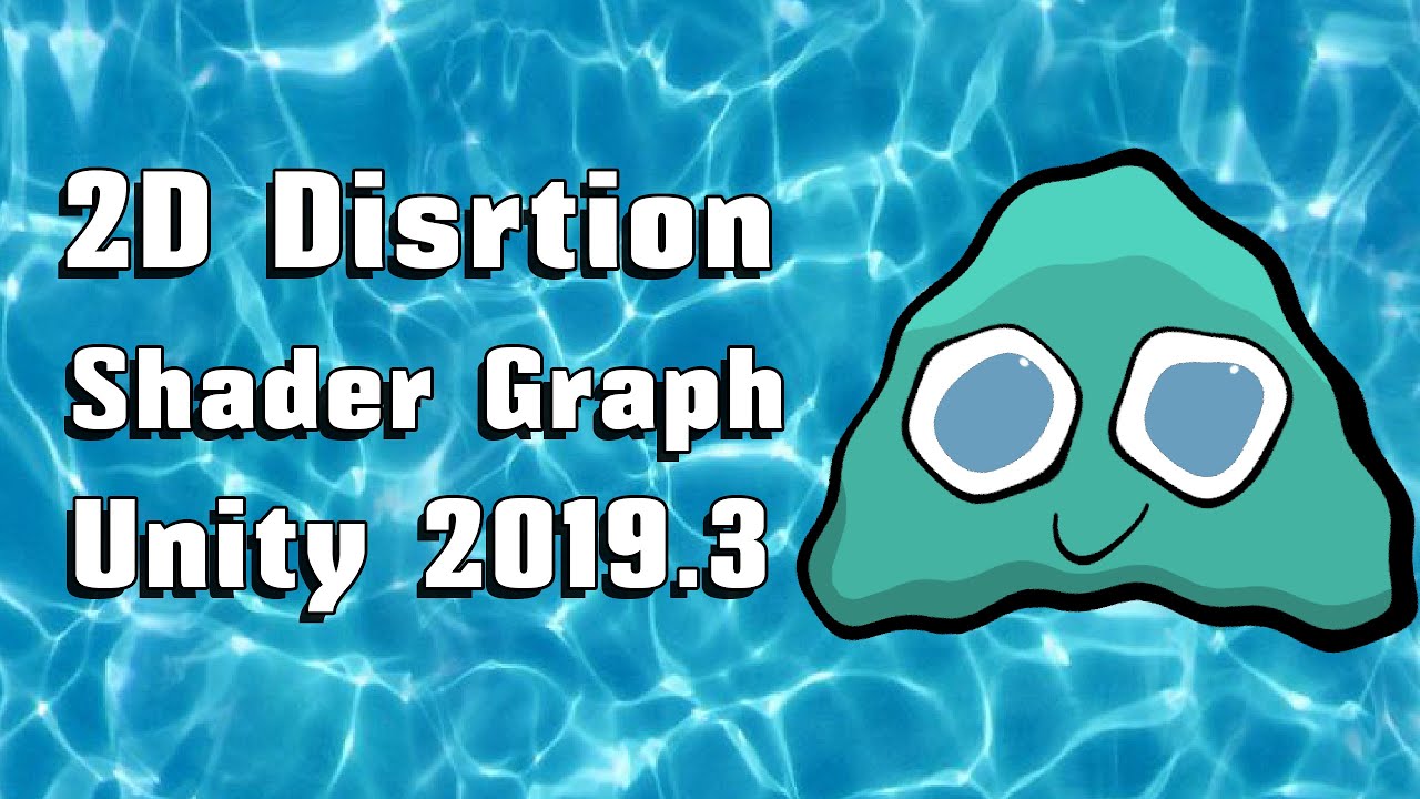
You learn how to create Distortion Shader using Shader Graph in Unity 2019.3 beta which depends on Universal Rendering Pipeline.
We have used the concept disclosed in the following unity video:
https://www.youtube.com/watch?v=atPTr29vXUk
Then we optimized that to work with 2D sprites by adding features to the rendering pipeline.
Shader Graph i...
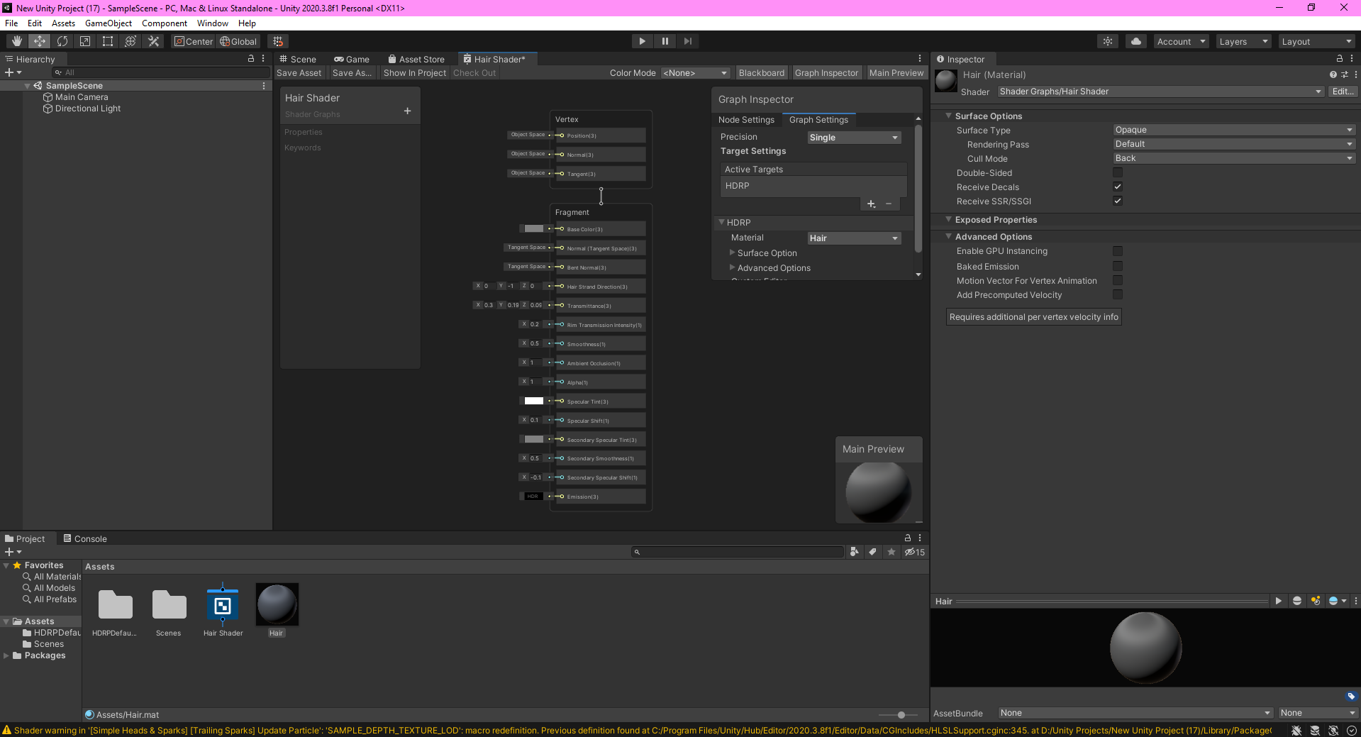
Hello. I hope this makes sense, as I am a beginner in Unity and coding.
I created a 3D project, installed the HDRP Shaders in my Unity Project and created a HDRP Hair shader graph for my characters hair.
How do I go about making it functional? ( Example: http://prntscr.com/138hult )
I will appreciate any form of information. I have searched Google & YouTube and cannot find this specific question anywhere on the internet.. Only about other shaders that I cannot purchase at this time. Thanks in advance.
If anyone needs any more information, I will definitely provide it for you. I appreciate any help I can get. 🙂
hey would it be better to implement a real time image denoiser in a compute shader, or is there a better place to do it? also are there any examples/code samples that I can use for denoising images in real time by chance?

Computer Graphics Stack Exchange
Image filtering operations such as blurs, SSAO, bloom and so forth are usually done using pixel shaders and "gather" operations, where each pixel shader invocation issues a number of texture fetche...


I've been trying to do a refraction effect on water and make it based on how far it is under the surface so the color represents how strong the effect will be.
For some reason, there's some white on the bottom of the screen that'll always be horizontal and is based on how close the beach model is to the surface of the water.
I disabled the water completely in the second picture (the water you see in the second pic is just part of the model)
Here's my setup (it's pretty weird since I've been trying to debug it)

I've been trying to fix this for a while and I'm pretty new to this so I don't know what's going on
I'm guessing for some reason the scene depth and screen depth of the pixel are getting closer to each other for some reason at that white part.
finally managed to make this goo shader! (its unlit :) )
is vertex displacement not working for visual effect shader graphs in 2020.3?
extremely simple graph, it does nothing when applied to an "Output Particle Quad" node in a vfx graph

Is amplify shader 'standard surface shader'
So how heavy is shader effect graph excatly?
I did make 1 graph, and it was enough to choke out my gpu with just 1 instance of running it
sounds like you made the exception, did your graph contain a loop?
A loop
Hum I'm not sure actually, pretty new to shaders in general
Let me send it to you
I don't really see a loop in there, but i could be wrong
It's the first graph that i made following somewhat of a very helpful tutorial
but it is a shame that it uses this much resources
I'm not about to open a random file, screenshot of graph or in the case of code can be enclosed in quotes or for large files use a suitable code posting site.
But that extension suggests it's Visual Effects Graph as in particles not shader graph.
it maybe a question for #✨┃vfx-and-particles channel
that does not read as visual effects graph 😉

visual effects graph uses shaders, it's not exactly a shader and there can be many things which affect performance
Would you still like an image of the graph?
Or should i ask in the vfx like you suggested?
I'd try asking in #✨┃vfx-and-particles as it's not my area and ppl who are better versed in it will be there
good luck 😉
How do u add transparency in shader graph? I am using a blend node and setting it to Base Color in Fragment
Am I doing something wrong? Also Color Out is connected to Base Blend
have you set the graph to transparent / tick box for opaque cutout, whichever is relevant?
Found under the settings when master node is selected
Umm I don't find any settings inside Lit URP shader graph ... U aren't talking about the standard shader graph just in case?
when you click on the fragment part (assuming recent version) you have following options

if you don't need full transparency, you can use opaque and enable the alpha clip checkbox to have an opaque cutout shader.
then it should be as simple as feeding your alpha into the alpha on frag, either from texture, mask or calculations etc.
if your using older version it's still very similar and lit / unlit makes no difference to this option
I think on older version was a cog wheel you need to click on corner of the node
Ahh ty man
Really appreciate it 👍
@arctic sierra All you've done is translate the verts by 1,1,1. So you've moved the whole thing over, up, and back, but it won't be changed in shape. Its center is in a different place.
I'm very confused, I'm using the URP Lit shader, with alpha blending, but my object is not rendering over the skybox. In fact it renders really inconsistently. Sometimes I'll see it rendered only over an object with the skybox drawing over the top (resulting in it looking masked)
here's the material

I tried changing the priority hoping it would render last, but that doesn't help
Ok I fixed most of my issues by changing my skybox shader from Mobile/Skybox to Skybox/6 Sided. there are still some cases where it wont render over an object, which is weird
It will still pay attention to the depth buffer and z-test against it. But it won't update the buffer for its pixels. So if it is positioned "behind" something, it won't draw over it.
There's another thing called z-fighting, that happens if the depth is identical to another object in the scene, so they "fight" over who wins or not, leaving weird results. If you think that is the case, you can slightly alter the object's position (by like .001 or something) to help deal with it.
And the skybox should be rendering BEFORE the transparent stuff renders. So that's weird.
@bleak stone
thanks for the reply! here's the issue in action. the game is paused currently

the teal rock going a solid color is actually a GIF artifact, sorry to be misleading there. the only thing that looks weird is the little sphere
If the other objects are using transparent shaders then this will inherently be a problem
ahh yeah good call. although the teal-ish rock has an opaque material, and then over the top of that, there's another material. but maybe thats causing trouble
heres that

heres an object with just one opaque material and its not drawing over the top of it

Change the shader to just output "red" in the fragment. Dump everything else other than clipping if any. Set frag color to (1, 0,0,1) and see if it still clipped. If so that would imply that there's a z-issue.
Thanks for the tip, yeah that helped me narrow it down, its not a clipping issue
I mean z issue
Otherwise, if you get a full-red circle, you've got a problem with transparency (alpha).
Yeah
Try doing some kind of max with the alpha value you're putting into the stack.
Like max(yourValue, .25) and then plug it in.
Just as a test.
It won't always translate. Particularly if you had a multi-pass shader.
With URP, if you're trying to read the "back buffer" what you get is really a one-time grab-pass that happens between the opaque and the transparent stages. So it won't pick up the other transparent stuff either.
That is if you're using the scene-color node (I think that's what it is called).
Gotcha, didn't know that. thanks so much for the help!
There are 102 objects in the Scene with overlapping UV's. Please see the details list below or use the 'UV Overlap' visualisation mode in the Scene View or Lightmaps in Lighting Settings for more information.

- Cube (13): 220 texels
- Cube (1): 191 texels
- Cube (20): 190 texels
.
.
.
I am trying to do some light baking, it was all good but now for some reason some objects aren't lit.
And i get this error?
What am i doing wrong?
Where did the models come from? Are they standard unity cubes or no?
If you're messing with UV's (or lightmap UV's in the 2nd UV set) that could be it.
I've got a shader that lets me have random slight tints on objects to give them a more realistic feel (based on their world position. Every object with the material has a different tint) .
One problem is that I can't mark them as static without the random part breaking. Is there any way to fix this or is this just something that happens with static objects?
What pipeline?
Static objects are often batched. Depends on your settings.
What can happen is that the engine takes a bunch of your static objects, makes a combined-mesh out of them, and sends that one big mesh in one draw call. There's limits, so it may have to do that in several groups.
There are other ways to deal with unique instance variables, but I need to know the pipeline you're working in.
@harsh marsh
URP
OK, if you're only tinting you might be in luck.
URP doesn't support material-property-blocks well last I knew. BUT, IIRC, it supports instances of _baseColor being set.
I'd have to test. Also what unity version are you using?
The alternative is to make materials for each block, and if you've got 1000 of them it's a pain.
2020.3.7f1
One easy thing you can do is make like 30 different tints (with 30 versions of the material) and randomly assign the material to the render.sharedMaterial property.
Then you can have 1,000,000 blocks with randomized tints.
and only use up 30 material instances.
Short of that, you need to research Material Property Blocks and see if it works for SG baseColor still.
SRP batches by shader, not material, so you can have several materials, but MPB's might break batching, I'm unsure of the latest.
Alright. I'll try that out thanks @meager pelican
Also, is there a way to increase the brightness of a color in shadergraph? Trying to port a blender material over and I can't find a node that's the same as Blender's brightness/contrast (which in Blender is only being used for the brightness part)
Hello, does anyone know how to get OnEnable and OnDisable callbacks on the ShaderGUI editor? I would like to be able to call some funcionality once user opens up material and sees the inspector, as well as when he closes it ..
Would there be any reasonable way to do that?
One way is to use the color space conversion node and then change the value param.
But depending on what you want to do you can just either shift it al up (adding some white) which will likely make it lighter too, or you can multiply it by some >1.0 value to keep colors proportional (myColor.rgb *= 1.3;) and that might be sufficient. If not, use the node, adjust it, convert back to RGB.
There's also a contrast node but IDK if that's what you want either.
Generally, brightness is additive and contrast is scaled, as IIRC.
Don't forget you may want to saturate it to clip any over/under values if you're not HDR.
I'm confused. I made an Image Effect shader, only change to the code was to put "Blend One One" to make it additive and then made a material that used this new shader. When I attach it to an object, its colours are inverted and it has this weird fluff around it.
I tried changing the blend type and removing the blend altogether but the effect was still there. The effects do actually work in game, it's just my sprite looks like this lol
Any way I can sort this? Or any reason why it's happening in the first place?

that's what it should do, but it doesn't do anything
it does seem that OnEnable and OnDisable will not be called on the material editor
you could have have a initialized bool variable that you check and if its not set do your startup code
and for closing the OnClosed callback
https://docs.unity3d.com/ScriptReference/ShaderGUI.OnClosed.html
made a shader which projects a HDRI in a way that makes it have a 'floor'

though this messes up reflections.

Not sure how to solve this. Is there a way to make it so it only changes the way the skybox looks to the camera so it doesn't affect stuff that's reflecting it?
In a Blender shader (of which this is an almost direct port of), I would just do this

Is there an equivalent way to do this in shader graph?
Hi, I'm afraid I've got some more deferred rendering questions - does Unity's world-space normals GBuffer require a special conversion/sampling to read from?
I think the values I'm getting from it are incorrect.
you can place reflection probes in your scene , they will override the sky reflection for the objects inside there affect area
they can use either a rendered image from where they are or you can specify a custom panorama
I'm making a wave system and, initially, I was manipulating vertices on a plane directly with a script, then using the values from that script to apply sufficient forces to a floating object. Now I've changed to using a shader to make the plane look like it's wavy, how do I apply forces to the floating object so it matches the movement in the shader? I think using a compute buffer might work but I don't know how to use that to do this
Thanks for the answer, I already thought of that, but unfortunately the OnClosed callback is only being called when you change the shader on the material, not when you click away, so I cant really use that ... It does seem like a missing feature from Unity's side unfortunately ...
Hello, I have a bit of shader experience with Blender, and I'm trying to learn Shader Graph now in Unity.
Is there an easy way to generate this "waves" style texture in Shader Graph?
I tried to blur the output of the "Checkerboard" node, but I don't see how to do that

Oh nevermind. think I figured it out!

I re-read your question. Yeah, the position is going to be maintained by VFX graph's routines, not the SG coloring, IIUC.
If you use your simple-translation shader on a normal quad object outside of VFX graph, it would probably translate it all. But VFX graph is making billboard quads and locating them and maintaining a particle system on the GPU.
So without having tried it to verify this, it seems the most plausible answer. Your quad locations are overridden by VFX's needs. Best guess, two cents.
that seems likely, thanks for the response
i got it working using the vfx graph, but it was a hassle not having the custom function block
I want to add some overlays and decals to weapons. I can implement a simple shader that receives an overlay texture and overlay it on top of base texture
Do we have a better and more efficient way to handle it?
@harsh marsh you can write an editor script that bakes the tint into the vertex color.
@toxic flume yeah, the most efficient way is hand modeling the mesh decals in a 3d modeling program.
A literal plane hovering slightly above the surface, that's what a mesh decal is.
Hey, sorry to bother again with this but it'd be helpful to know if the deferred rendering path normals gbuffer requires any special decoding, as I'm getting obviously wrong values.
can someone tell me, why when I click to open the shader instead of opening the editor it open the visual studio?
Opening what editor?
the shader thinggy
If you created a shader file instead of a shader graph, you can't open it in Shader Graph.
Shouldn't .shader files normally open in your assigned code editor?
I click create, shader and unlit shader
Nope, you need to create an Unlit Graph.
sooo how can I create it, I don't have that option
Did you actually install HDRP or URP?
yes

but I have to have a complete big texture for small tattoo for example, right?
because only a small part of arm has a tattoo
Even with mesh decals you aren't using the texture of the main object. You use a separate decal atlas.
People usually pack many decals into one texture.
My main texture is 2048*2048
I should use the same size for makeup or tattoo as well, maybe I can scale it by 2, OK thanks
They are not static. The player can change it in runtime and choose between them
Hmm, for tattoos, I'd maybe texture swap instead.
So basically you'd create a full body texture for each tattoo using the same uv map and then you can mix any amount of tattoo textures on top from the skin shader.
Yeah, it's perfect.
anybody seen errors like this before?

I keep getting them when writing shaders and googling this hasn't turned up anything
IIRC there's macros for encoding decoding normals. Something like unpackNormal. And in SG there's a setting to tell it the texture is a normal map, but if not, you can also use an unpackNormal node:
https://docs.unity3d.com/Packages/com.unity.shadergraph@6.9/manual/Normal-Unpack-Node.html
Now I know you're dealing with the normal buffer. But there's got to be some code out there somewhere
That you can see a sample of. (See below for DecodeDepthNormal helper function from UnityCG.cginc.)
Okay so weirdly enough subtracting vec4(0.5,0.5,0.5,1.0) from the raw sample gives me a correct result
Now I'm getting these darned source component initialisation errors?
Normals are kind of "encoded"
IDK about that one. Temp r1? Weird
It's implying that a z or b component isn't initialized.
Worst part is that I can't find anything on google
It's very likely some hlsl compiler error
some optimisation probably
This builds a screen-sized 32 bit (8 bit/channel) texture, where view space normals are encoded into R&G channels, and depth is encoded in B&A channels. Normals are encoded using Stereographic projection, and depth is 16 bit value packed into two 8 bit channels.

UnityCG.cginc include file has a helper function DecodeDepthNormal to decode depth and normal from the encoded pixel
value. Returned depth is in 0..1 range.```
https://docs.unity3d.com/Manual/SL-CameraDepthTexture.html@mystic trench
I'm a beginner with shaders and I've made a few attempts at recreating the grass effect shown in this video:
https://youtu.be/thUXblUXKeU
My last attempt was to calculate random positions on a ground mesh's surface and to then use Graphic.DrawMeshInstancedIndirect() to draw a large amount of sprites in those positions. This worked, but has a lot of issues like grass clipping through objects. Could anyone guide me to how the effect in the video works, and how I could go about creating it in my game?

Date of Recording: 2020-10-04
To avoid popping issues, grass is shaded directly, by transferring the world position and normal of the base terrain in 3D, which does not change frame-to-frame. GPU instancing is used for performance reasons. A random subset of the grass is given a separate sprite and a randomized color, to add visual interest.
Doh, thank you @meager pelican
Okay so I figured out why the colour was all weird, but this background colour still persists. I need the sprite to just be the flower. Any way to get rid of the weird edges?

it basically tell me this

Hey guys! I'm creating a dissolve effect that applies to all materials in a scene that fades when far from the camera, but I don't know how to apply this effect to all materials in URP, without needing to create a shader variant to each material type. Someone knows how to do this?
Also, some materials use hlsl written shaders, so creating a sub-graph won't work in my case.
@meager pelican Welp, still getting this compiler error with that uninitialised value stuff
@charred shore then look up how to set up your pipeline cause it looks like you just installed the package without doing thr necessary steps afterwards.
Okay, I don't want to tag the unity admins in case that's verboten, but is there somewhere I can register this shader compilation bug?
I can't find any answers on it online or on the existing unity bug tracker.
I've tried that, but it gives really weird reflections for surfaces that aren't perfectly smooth

Even if I set metallic to 0, I still get a hint of the reflection still in the sphere

I fixed that but now I can't change the skybox
Hi! I have a little problem with shader in Unity. This is portal shader and when I try to use him on my mesh I see very strange result.
I understand that the problem is UV, but i have any idea, how I can fixed it.


IDK what that one is. Sorry. 😦
Yeah and the worst thing is that I can't find anything online about it
and the unity bug tracker doesn't seem to have anything?
Hey I've been trying to follow this guy's tutorial https://youtu.be/kgXeo2SRDd4?t=401 but I've gotten to a part where I get a problem that he doesn't get. In the depth mask part of the video, he shows the depth of an opaque object below the water using color with white being close and black being far. I tried using my own method to do this a few times and it worked except for the problem shown in my video. That white part of the bottom of the screen was always there no matter which method I used. I even tried his own method exactly but I still got the same problem. If anyone knows anything about this please lemme know (I also show some URP settings in the vid)

In this one we us a texture based displacement map coupled with a normal map, both made in Blender (not shown) using the ocean modifier. Really simply stuff, but amazing results. We're also using refraction but not in the same way that everyone else is using it, so that's either good or bad.
● Support Links:
♥ Subscribe to learn more!: https://...
Is it possible to make an outline shader for pro builder objects? I'm looking for an effect similar to this:

I want the outlines to be as they are when I select a pro builder object
Any ideas?
I'm trying to create a shader for the skybox that reprojects an HDRI/Cubemap in such a way that it creates a floor.
Might current implementation is fine but has quite a lot of distortion around the edges of the skybox.
I looked around and found this https://twitter.com/Cuboxel/status/1291900082653102080
My current implementation is a port of a blender shader so I tried porting this one over using the screenshot provided by Cuboxel. Problem is, all of the important nodes are collapsed and some even have hard coded values which can't be seen when the node is collapsed, making it impossible to recreate.
Because @cgonfire and @LucaRood shared their ground projection shaders, here is my version with no distortion and a border sphere #b3d https://t.co/0mqQwlMbrX
Likes
332
aagh this is annoying
how do i fix this z fighting? (is this z fighting?)
its just a transparent shader
so if I have a compute shader that does a bunch of stuff, but another compute shader that does denoising of the output of the first compute shader, what would be the fastest way to get things like a normal map, distance map, etc. from the first shader to the second shader?(first shader is a raytracer, second shader I want to denoise the first shaders output but idk what would be the fastest way to send the needed data from shader 1 to shader 2)
Does anyone have a shader that can use a collider and then hide part of a specific object? like for example if you had a black image and a 2d circle collider and you put that collider in front of the black image its like a transparent circle?
Black is the image, green is the collider and yellow is everything behind the black image

@meager pelican sorry for the ping, but i thought you might be interested, it turns out that vertex pos is in the VFX Graph product roadmap under "in progress" https://portal.productboard.com/unity/1-unity-platform-rendering-visual-effects/c/106-particle-s-vertex-position-normals-modification
so it's not possible now, but maybe a year from now
So in my shader graph I am using a gradient node on to sample gradient . Now the gradient node is half transparent but in sample gradient ( Time setting is connected to split from UV ) it doesn't show itself as half transparent ;-; . Any way to fix it?
Basically I mean .. in gradient node.. u can change transparency but when u connect it to sample gradient..all the transparency changes to black
anyone got an example on how to create neon light of polygon sprites like this:

bloom?
how do I make it not affect the white line itself? Using URP and 2d light (very new to this part of unity)
bloom.
should I make like a diffuse emission part or just use the same texture(the pentagon). Does feel like it blooms over the white part as well. Also, any way to easily get more aliased lines?

Imma wait xD
I think using the same texture is fine.
Hey! I'm getting this weird border around my sprite, and cant figure out why it is happening. Do any of you have a clue?:)

Should have looked like this

How would i go about making alpha stay the same and not blend when it overlaps?

I think i am searching for a similar shader as you carnate
Not completely familiar on how this affects alpha, but you could try using different blend modes in your shader. Ideally you'd want a "max" blend mode or something similar
if im using a compute shader to write to multiple textures at once, is using a bunch of rendertextures the only real way? I want to pass it to a shader that does denoising, but I still need to figure that out at alll
also are there any online examples of using a shader in unity for denoising I can look at the code of?
Hi All, just learning shadergraph currently, and wonder if there's a way to use the base lit material as, well an input to a graph? I've seen some talk of custom masternodes, but honestly, it's a bit over my head.
Waiting xd
How are the settings on the Sprite Import Settings? Did you disable Alpha is Transparency?

are there any good examples I can look at for image denoisers or such in a unity shader? trying to learn things like temporal reprojection and denoising for this but im quite lost
If I am getting 2 errors of "floating point division by zero" but my graph works then do I have to worry?
Like Ik the meaning of error but Idk why it's happening after looking at shader graph
Leaving the image here (plus I also added a split node ('A' output is connected to Alpha input from the sample gradient node) so I can get output for Alpha)

Hey does anyone know where I could download/create some 3D noise textures? Many thanks 🙂
would it be better to store each vertex and UV in one structured buffer, and a list of indices in another structured buffer(both being very long) for frequent reads in a compute shader, or would it better to, instead of both of those, have one big long structured buffer that stores every triangles 3 verticies and 3 UV's in one entry?
can I add a property to a shader that changes how it reacts to directional light color? for instance I have a yellow tint directional light but I want characters to not be affected by the directional light yellow tint
or would it be worse for performance if I pack a structured buffer of indices into a structured buffer 1/3 the length, but holds 3 indices per entry?
so i guess essentially, why does having a structured buffer made out of a struct of 3 int slower to read from than a structured buffer made of ints thats 3 times as long
@grand jolt did you ever find a solution?
No
Having an issue where when I replace a constant with a parameter (so that i can treat it as a user-exposed fine-tunable constant) it does... odd things, and the modifying the parameter does not affect the result.
defining the property: _SourceRadius("Source Radius", Range(0.0, 2.0)) = 1
declaring the variable in HLSL: float _SourceRadius;
using the variable: Out.sourcePos.xyz = Out.sourcePos.xyz + normalize(cross(cross(sourceNormal.xyz, -h.xyz), sourceNormal.xyz)) * _SourceRadius;
using _SourceRadius, it seemingly acts like it's either 0 or 0.1 depending on unknown factors. If I replace it with a constant, it behaves just fine.
... side-note, don't know if it's related, but i have a division by zero that i can't seem to get rid of?
if (sourcePlaneVecLength > 0.1) {
    float3 tmp1 = sourcePlaneVec / sourcePlaneVecLength; // division by 0
    // snip...
}
oh that's probably just optimizer turning conditional code into branchless code
.... nvm, still divides by 0 if i replace the conditional with making the length = min(length, 0.1). somehow.
Waiting xd
Maybe some cosmological constant changed, and all denominators are now magically zero. Giant Meteor 2021 comes next....
Seriously, IDK.
Note that NaN's might slip through. But I don't see where NaN is applicable to either of the 2 questions. @grand jolt @alpine blaze
So can be a bug or something? Cuz shader graph still seems to work..
I myself don't know where I am dividing by 0 ;-;
Zero is a valid index/offset for sampling a gradient anyway! The others are a uv output and a split and a gradient source. So it could be on their side. IDK. Where does the error message appear? At run time? In the graph? On the console?
It appears in inspector in the shader object
With yellow warning triangle ( not red one)
I didn't even know it has those errors until I looked at inspector tab lol
lol. IDK man. That's the output of the shader compiler showing up as an warning/error in the inspector.
I'd make sure packages are up to date an in sync, but other than that....
Maybe try another simple shader where you just output a color from the blackboard. No gradients and whatnot. See if the error is still there. If it is, it's probably in their compile/libs and not your specific graph.
Actually I checked my other shader graphs having Fresnel effect etc and they didn't have that error
I didn't use any split or UV or geadient node in it
IDK
Btw unity is asking me to update ( I didn't update yet)
But I don't think 2020 verison will have any problem
Np . Thnx for trying tho :D
Just check package manager even for your current version. Other than that, yeah, upgrade MIGHT change it. I haven't seen this.
Ok Imma try that
I am having the same type of error lol in shader graph
@lean lotusAll you can do is test. This is similar to a DOTS thing, but on GPU. lol
I was wondering the same thing today. Was ray-tracing and I added in normals to the data structure. Was wondering if I should have a separate buffer for them, similar to verts, or make a vertexData struc that had both vertex and normal in it.
I went with the latter option. Figuring that when I wanted the vert data, I also wanted the normal-data, and thus I'd have been local cache consistency with having them together since I was reading through sequentially.
yeah i tried isnan and isinf and they say that it's impossible for it to be either nan or inf
So it's probably just a bug?
¯_(ツ)_/¯
You guys should check unity answers or whatever, bugzilla thing.
idk. updating unity (2018.4.20f1) is not an option for me since it's content creation for an existing game (vrchat). i don't actually care about the division by 0 itself (the shader is more or less behaving itself), just thought maybe it could have something to do with the weirdness i'm seeing with the parameter stuff.
Oh
@alpine blazeOne thing to check is your graphics drivers...updating if you can. The GPU-side shader compiler might have a fix in it. Long shot.
Otherwise break that expression up and see if you can side-step any optimizer problem if that's it.
I'm at a loss.
float3 sourcePlaneVec = cross(cross(sourceNormal.xyz, -h.xyz), sourceNormal.xyz);
float sourcePlaneVecLength = min(length(sourcePlaneVec), 1.0);

if (length(sourcePlaneVec) != 0) {
    float3 tmp1 = sourcePlaneVec.xyz / sourcePlaneVecLength; // division by 0
    float3 tmp2 = tmp1 * _SourceRadius; // this multiplication seems to either be a fixed 0.1 or 0, regardless of actual _SourceRadius value.
    Out.sourcePos.xyz = Out.sourcePos.xyz + tmp2;
}
right i forgot to post my changes based on trying to dodge the divide by 0 to see if that would fix it.
So it's still showing the error?
still has the divide by zero warning, the parameter still doesn't behave.
Shader warning in '<snip>': floating point division by zero at line 189 (on d3d11)
Try
sqrt(dot(v,v))
instead of length()
no change
Same line number?
yes.
yeah, i know. i'm just laughing at how much i hate shaders rn. >_>
I checked google and read somewhere to update shaders or might be a GPU issue
And my GPU is really old
Yeah. Drivers and/or whatever on the hardware side could do it.
thing is that google will have some site that always says something like that regardless of the issue.
yeah
so forgive me if i don't put much stock in that
Well it's unity forums site ;-;
After a while GPU makers just quit supporting them.
Hmm
I saw an ad today for helping upgrade Windows7...
lol. I mean.... oy
IDK what to tell you. That sucks man. Feeling for you. But there's so many layers of old stuff....that you cannot upgrade.
without changing Win7
Hmm ;-; welp
side-note, changing the parameter into a static const float fixes my issue with the parameter, but maybe that's because the compiler is just inlining the const then. (also, well, it's no longer a parameter, so not a real fix)
Oh ok
(that's separate from the divide by zero, which i'm suspecting is just unrelated)
Yeah, that's probably what it's doing.
still works with a static float, probably same thing.
Make sure you don't have a typo such that the variable name is different and uninitialized. But if that were true you'd either get a 'variable undefined' error or you'd have to have two of them in there.
lol. Yeah, you saw that coming.
XD
so, fun thing, i don't get any warnings (and the same behaviour, except i don't have a user visible property) if i comment out the property definition and leave the hlsl declaration.
ctrl-f with match case on tells me that the 3 instances i brought up and posted when i first talked about it here are the only instances, and that they do seem to match.
dafaq. hold on, give me a sec.
??
That's a hisenbug if i've ever seen one.
so I decided to try and debug by muliplying the color output by my shader parameter
Oh
and not only does darken/lighten the color, it starts working properly.
lololololol
Maybe an optimizer bug? Now it has two references to it.
So it deals with it differently
IDK
i. ugh.
maybe it doesn't like that the only reference is in the constant hull shader or something.
so when i added a reference in the fragment shader it went "oh! i can deal with this!"
the constant hull shader, yes, since i'm using tessellation. nevermind that i could just replace the tessellation with a mesh with equivilant geometry, since it's literally just acting as a detail slider for the shader, and no input geometry is actually used.
this is a weird shader
but i also kinda highly doubt that's the actual issue?
nope, that can't be the case, since my _Iterations parameter (determining the number of iterations of newton's method to run) is also only used on the constant hull shader.
I've had a weird thing before where Unity's shader compiler (the one that outputs the IL code for the target hardware to finish compiling) would skip a variable because it thought it wasn't used. That variable was in a conditional compilation stage that had some weird configuration. Turns out you can check for some kind of analysis step too in the if().
But that doesn't sound like your case (that you have conditional compilation).
not anywhere in the constant hull shader, no.
Yeah, but it kind of sounds like what you did. Because when you referenced it in the frag, it "sees" it.
yeah
So the issue got resolved?
You might be able to "trick" it by adding your color multiply thing, but only for the analysis stage.
like
      do your thing
#endif
IDK if you're doing a surface shader though.
Maybe there's a similar thing for vert/frag or whatever.
Damn shader codes look so much tougher than shader graphs
It is a known limitation of the analysis phase. IDK that it ever will change.
that doesn't work.
#if defined(SHADER_TARGET_SURFACE_ANALYSIS)
return i.color * _SourceRadius;
#else
return i.color;
#endif
gets me back to the parameter not affecting anything
oh.
But maybe there's a similar thing for other types.
Oh
Btw I tried updating the packages and still the issue is there oof
So I should give up for now?
Cheat
yeah btw none of this is talking about division by zero stuffs anymore
???
this is referring to my other issue which is apparently completely unrelated
Oh
You have a solution that works. You don't care about it in the frag, but you need to reference it.
Do you have a vert() shader
@alpine blazeit MIGHT be related.
Anyway cheat.
i do have a vertex shader, it does nearly nothing
In the frag, or in the vert, reference that variable.. Try vert first, since it has a lower invocation count. Then try frag.
But you can just set it to zero then do an add with it or something. Or increment it. Something that looks low cost and harmless.
setting it to some constant means that it then just turns into using that constant and it stops working.
i'll figure something out.
If it is an optimizer thing you have to USE it on something that sticks.
If you just set it to foo, then never pass it out anywhere or use it anywhere, it gets optimized out as a useless variable.
That's what I'm thinking happened. But when you used it in the frag and actually multiplied the color by it,
it was seen as a "really used" variable.
i was referencing the set it to 0 part of it -- i did the multiply trick but set it to 1 beforehand.
yeah that's what i figured
bot doesn't like that i guess, huh
What's your v2f look like? Maybe you can pad something out to a float4 from a float3, and then stuff the <variableName>.x component into the thing.w.
i think i can figure it out from here, i was trying to post one of the things i did that worked but bot kept deleting the message.
it boils down to 1 + _SourceRadius * <small number>
i can't post said small number because bot keeps deleting it

@meager pelican sorry to ping u again.. I think this error is happening for every sample gradient node assigned to Base Color.. can you check just to confirm my suspicion XD?
if it was not answered yet, that is caused by the sorting of 2 transparent things, if you have them at maximum alpha, they are still considered transparent, and they will get sorted by the distance to the camera. you could try to have them as opaque cutout objects, if the floor is not visible through the goo. if they need to be transparent, try to play with blending modes, and ztesting maybe that would solve it
or render them yourself and you have control over the order I guess
Also you might want to try using offset (assuming it's z fighting)
https://docs.unity3d.com/2021.2/Documentation/Manual/SL-Offset.html
Hi, I need your help again with a graphic problem. A transparent model, made by a graphist, render like this :

as you can see, a face of the pillar is hidden by the face behind
i don't understand if it comes from the model or the shader (standard specular setup)
this should look like this (but with transparency)

i'm lost since 2 days, so thanks for the help if someone has an idea
a last image with standard shader (transparent), this is Unity 2021.1.7

the tower should be in front, but it's hidden, don't know why
Might be the wrong channel, but how would I go about getting the depth buffer of a camera as a texture?
Hello! Im new to shaders and Im trying to find a shader which is a gradient with transparency. I found one that works but it does not handle textures. Is there a shader where one can create a transparent gradient for textures? The purpose is fade in a tower in AR to smooth over the occlusion edges
this is typical z-fighting, there are a few options each with their own issues. I usually suggest transparent dithering which is an opaque cutout shader with dithered alpha giving you the benefit of proper depth sorting. Here is a good explanation of the technique and why it is used https://danielilett.com/2020-04-19-tut5-5-urp-dither-transparency/

Daniel Ilett: Games | Shaders | Tutorials
Drawing objects with dithering patterns
Thank you, i'm reading it !
The most common way to deal with actual z-fighting is an offset, from what I've seen.
@cursive surgeYou can make such a gradient in the unity editor. Use their editor tool to define a gradient. Then, you'll have to write a script to create a texture from it. Say a 1x1024 texture. Sample the gradient along intervals 0 to 1023 and use setpixel to set the value in the texture. Make sure the texture format supports alpha.
Then just pass it to a shader (sharedMaterial.setTexture) or whatever you want to do.
In the shader you can do whatever you're wanting to do. Like multiply by the gradient alpha. Whether you want a full color or just an alpha value, IDK, I'm not sure what you're doing.
@grand joltI'll check in a bit, but we might be on different versions.
I updated to the latest one so dw xd
how to scale the final texture?


@grand joltI hate deciphering graphs.
Have you tried the tiling and offset node to scale the UV's?
yeah
Also check texture import settings for sampling mode, like wrap vs clamp vs repeat.
Can be set in script too: https://docs.unity3d.com/ScriptReference/TextureWrapMode.html
@grand joltRefresh my memory, was it lit or unlit? (what type of graph)
doesnt work
I wanted to make an area light, but it doesnt work. The whole area is set to static. I tried it to bake it manually too, but still doesnt work. Even with itensity and range up to 5k

I also tried to set the light to static
Lit
Btw it's working in neither xD
Second, going back to look at your pick. We all talk too much 😉 :p
Np xD
Creating Graph, please stand by. One moment please. Your regular programming will resume shortly.
Lol btw I think I deleted the shader graph earlier..shall I resend it?
tiled correctly on the sides, not correctly on the top

I have the pic
It's a simple graph. I've recreated it, just trying it now
I didn't see an error. Where do you see it? Console?
No no
Click the shader and see the inspector tab
Does the graph look similar to this?


Yep works for me as well but the error still shows in inspector tab
No error in inspector tab?

Yep I am doing the same thing with red gradient
Wrong person hled ( @dense violet response to your question here)
No error in inspector for graph, for material, and no error on console
Oh But my package is also updated and the unity version as well hmm
And we did the same thing
@dense violetSee above.
@cursive surgeSorry. My bad.
(No worries)
Or unity software versions. Or or or.
I hate this type of thing.
Maybe make a clean project, new, and just do one graph+material. Separate directory. Maybe your install is f-ed up.
Or maybe your project.
Or like you say, OS, or drivers.
Oy
;-;
Welp badluck ig
Btw what's ur current unity version? Cuz I don't think unlit master node is there in 2020.3.9f1
That's from an older test rig/sandbox.
That one was 2019.4.23.f1
but I have others installed too, but they aren't URP right now, and I didn't want to wait forever for a new project to be created (slow for some reason)
Hmm
Well since the gradient works..shall I go with it and don't worry about the error?
Or use a different approach like gradient inside an image used as texture?
IDK man, I worry about everything. I'm a worrier!
XD
I am gonna install an older version like urs to check if the error shows in it .. Imma tell u the results xD
I'd use another approach. Including math. If you just want a red gradient, that's just he amount of red. Maybe invert the y. Stuff it into color.r.
By invert I mean 1-y
Ohh
In your case looks like you're doing alpha too on the gradient. So you'll want to figure out the values at different points and then figure out what math to do to get what you want.
The SG docs have a calc for gradient, IIRC. You can do it with math.
It's basically a lerp anyway, but maybe skewed t
Or sampled values lerpted in a loop
Hmm Imma check the docs soon
The cool thing about doing it in a texture from the editor is that you can use their gradient tool in the editor. Then just stuff it into a texture, and let GPUs do what GPUs do, and sample it at "t". So you pass in the texture and t.
Then the sampler takes care of the rest, smearing the colors in-between to any t. That's what GPUs do for a living anyway. 😉
XD
The drawback is that you have to write a script and make another texture, and you might just be able to do it all with math (which is faster usually).
I like how there can be so many different approaches
But that was the simplest one ;-;
I was AFK.
Second, have to restart unity. Have an idea.
Np. Is idea related to my question xD?
Prolly not. :p
This is what I get:

Oooof
Now this error is even worse than before. Because before I thought it's from shader but now I don't even know from where it's coming ughh
Thnx again man
U specially turned on unity for me 😭
OH!!!!!
I GOT IT TO SHOW UP!
I clicked on "compile and show code" button. THEN it showed up.
If I go back into shader graph, save the file again, it is fine.
So it might be a spurious error from the "compile and show code" thing in the editor.
@grand jolt
I am confused
So the error showed on clicking the button?
how to fix my shader? looks correctly on 1, distorted on 2, and completly broken on 3


Yeah, I guess. It starts off clean, like in the pic I posted above.
Then I click "compile and show code", and I got the error somehow.
Then went back into SG and saved again, and the error went away.
It was weird
But maybe it is just shader variant. Are you writing for DX11 or for Open GL or what?
What is your target?
Like if you do a build.
I- didn't make any plans for that ...
Shader varient?
Also what's the default
Variants are activated with different keywords. Like has shadows or not. Things like that. So you end up with multiple shaders output with different options active. Allows for smaller shaders. Then on build, unused variants get stripped.
Ohh
Default my vary depending on platform you're working on. IDK. Seems like I always end up with DX11 and Windows. But I really haven't worked in other environments with the editor (such as Linux or apple's stuff).
So u said error showed up for u as well
But now it disappeared
U know the reason behind it? ;-;
Compiling Fragment program
Platform defines: UNITY_ENABLE_REFLECTION_BUFFERS UNITY_USE_DITHER_MASK_FOR_ALPHABLENDED_SHADOWS UNITY_PBS_USE_BRDF1 UNITY_SPECCUBE_BOX_PROJECTION UNITY_SPECCUBE_BLENDING UNITY_ENABLE_DETAIL_NORMALMAP UNITY_LIGHT_PROBE_PROXY_VOLUME UNITY_LIGHTMAP_FULL_HDR
The full error that showed up was this. See all those active keywords?
IDK. But might be spurious.
I cannot tell.
Like error was false?
More like not applicable for the variants you really want. But IDK for sure, not 100% sure how to tell in this case and I'm having a hard time reproducing it again.
OTOH, you get it all the time.
OTOH means xD?
Sorry. On The Other Hand.
Aye don't say sorry
😉
Maybe make a bug report and let the experts deal with it, eh?
I mean, you can make a project, isolate it, and reproduce it.
But give them your hardware info and versions in the report....windows ver, graphics card, driver versions....
See if they can tell you anything.
Worst thing would be you getting a "not reproducible" answer back, or an "upgrade it to fix it" thing.
Hmm I think that's the last resort
Again thank you for helping!
np.
Here's an old one from > 1 year ago, so you can see what they look like if you haven't seen them:
(Not exact same issue)
https://issuetracker.unity3d.com/issues/shader-shadergraph-errors-do-not-clear-from-asset
Steps to reproduce: 1. download project and open scene 2. open "broken.shadergraph" 3. select custom function node and remove "//" (...
Okey dokey
@grand joltOne thing that might be worth checking is:

that you have it set for the current graphics device.
It is
Why it shows 5 variants included
For me it's 459
I'd ask unity, send them a repro (small mini project that reproduces it on your system) and system specs. Other than that, I'm not sure but we're going to fill up discord here and not get any further.
Try to check the database first to see if there's a report already there.
why does compacting a structured buffer to 1/3 the length but having each element now have 3 ints instead of 1 half my performance of a compute shader?
was trying to compact a list of mesh indices
perfect, i’ll try this out
The other thing with GPUs, IIUC, is that they love things that are aligned on float4 boundaries. That works for int4 too. 32 bit int or 32 bit float. So 128 bit boundaries.
It's not uncommon to "pack" structures into various4 variables, and also to pad things out to float4 boundaries. But don't go nuts.
And if you spit the one buffer into 3 buffers, you end up with memory cache locality issues since you have to jump around and read from separate buffer memory areas to get your data assembled.
@lean lotus
I had a long structured buffer of single ints
I turned that structured buffer to use a struct of 3 ints(plus. a fourth for material info)
that lowered the length of it by a factor of 3
but now my performance is half
this structured buffer is very frequently accessed
Are you updating it? (RWStructuredBuffer) or just reading it (StructuredBuffer)?
If the first/former, I'd guess you're "locking" greater strides. That may or may not be a problem depending on what you're doing. If each thread has its own area to update, might not be bad.
The other thing you can check is your wavefront. You'll need analysis tools for that from your GPU vendor. Like Nvidia or AMD. They have tools that can tell you how many cores are running at once in the kernel dispatch. There's limits to threads dispatched based on things like available vector registers, and that's all relative to the code that gets generated. So maybe the code needed to access those changes is larger, and results in fewer cores dispatched.
This is all off the top of my head an a bit of guess work. But there's no easy way for us to answer your questions with such a simple description. You're going to have to dig in using your system and the right tools, IMHO.
Well, then there's Macs....lol
So IDK. What do you mean "right now"?
You're comparing apples to apples,, of course. Right? So changes on same system are twice as slow.
yes
IDK why just having a structure would slow it all that much, but who knows?
What were you doing before, just offsets?
Like buff[index] and buff[index+1]?
its an indice list for raytracing, so its read many times, but thats all im doin
yis
thats how it is now
if I compact it, that means I just read index buffer 3 times, but with a different element each time(indice 1, indice 2, indice 3)
but by doing that I go from 50 fps to 20
But each was an int before. And now it is a struct?
yes 4 but thats unneeded rn(its material information for each triangle, which is why im doing this at all)
Show me the struct/buffer definition
I just did this with three-eyed game's tutorial on ray tracing. But the impact was the scene objects, not the buffers.

IDK. That's interesting to find out. Wish I had an answer other than the guesses so far.
mhm
its really annoying
but I may have to bite the bullet and just take the drastically lower framerate
unless I wanna send in yet ANOTHER structured buffer(im up to like 5 or 6 rn)
its all so I can have triangle specific materials
What about making it an StructuredBuffer<int4> in the shader, but keep the struct on the C# side? It should translate the bits properly.
Yeah, good idea MS
int4... I can do that?
Yeah, any scalar type HLSL supports can be made a vector that way
yes, GPUs live for that
huh ok
but i still just define it as a struct on the C# side?
Yeah, you shouldn't need to make any changes on the C# side
ok lemme try it
The tut I followed just did buffer of [int] and then accessed with [index], [index +1], [index+2] and they calced the index value from the triangle's offset and the mesh object offset. But reading them all might work. Since they're index values into the actual vert buffer.
mhm ik
i started with the tutorial form threeeyedgames but its results were much too slow for complex scenes
so here I am now
Yeah, that's the one I just did (again). He just did ints.
But it isn't optimized for access. That was going to be his part4 or 5, but not written (yet?).
There are various methods of having "acceleration structures" that allow you to not have to read everything in the scene for every pixel.
mhm I have accelleration structures
that 50 fps was for a 143k triangle mesh on mac with primary ray only
hmmm still going from about 40 fps to 25-30 fps with this, ugh structured buffers are so confusing/mysterious in their performance to me
You said this buffer is accessed very frequently. Do you mean it's accessed in many different shaders or it's accessed multiple times in one shader?
many times in one shader
Usually many times per pixel (many rays for each pixel) and x width x height
But if he has acceleration structures, he can reduce the total # of accesses.
Right......
But see what Trace() calls, and then it will call IntersectMesh for each mesh you have. And that romps through the triangle forest and does an intersectTriangle test.
At least for those that pass your acceleration structure test.
And he scatters several rays per pixel and accumulates them from a hemisphere pattern
trace calls the top level BVH
the top level BVH then transfers to the many bottom level BVH's
then the bottom level BVH's access the triangle index list, the triangle verticies, and the textures
ok uhhhhhh i just decided to add ANOTHER structured buffer of ints that stores the triangle material for every triangle
and performance is now improved because I replaced a bunch of things that stored material index with searches into this new structured buffer
OK, so accelerated. But still, major romping. Each pixel has many rays accumulated over several frames and added in.
how the hell do structured buffers work for performance... this is so confusing...
but ive gone from 40 fps to 50-60
by now having it look at a much longer list, but each element only contains a single int, vs having it look at a really short list but each list entry has like 5 or 6 different data values in it
It all depends on what you were doing.
it seems that eliminating any extra data stored together seems to speed it up? idk compute shaders and structured buffers are such a mystery to me in terms of performance
If you accessed the 3 ints, then you read the 4th material, and then you went and looked at a material buffer, then tried to go back to the index buffer to get the next triangle, you were jumping around in memory. So when you do that you invalidate the memory cache, and get more "misses". Guessing.
idk anymore
we need like a comprehensive review and look at the performance effects of different ways and constructions of structured buffers
my only guess is that when I have 4 ints in one entry of a structured buffer, every time I need to access one element of an entry of it, it needs to load the other 3 entries? idk
Then there's added that 4th byte increased the data throughput needs by 25%
Sure, that makes sense if you have it defined that way.
Like with int4 or with a struct.
But the idea is that you need all of them anyway, so you know you're going to access it like that anyway.
yeah
143K triangle mesh? once you go beyond your 1 ray, kiss it all goodbye anyway. I hope the BVH helps you a lot.
What BVH implementation did you use?
it do help a lot
I started with octree, moved to bottom up BVH, now im on the Top Down one by MadMann, they have helped a LOT
I added materials and normals.
But mats sure weren't per-triangle. 😉
Then again, normals are. Was a separate buffer.
With barycentrics on the normals (optional flat).
mhm
Im working on getting textures to play nice if I decide I want to make a single BVH from more than 1 mesh or submesh
Cant think of how I want to have this structured or defined for grouping
Well, now you need at least a float2 on each triangle vert for UVs. So you may run into the same things again.
And then there's a texture atlas array that has to be all in memory at once.
lol
Starts to make your head spin.
I have that already
and the texture atlas is done
textures work fine rn
but I wanna group together things that heavily overlap
I imagine what's going on is transparency is not being taken into account for the sprite. I can share the code for the shader if need be
First check the import settings on the texture and make sure it is importing alpha. Then you can show the shader code.
What pipeline?
Do you care about mobile or not?
Is this what you needed for the first question?

Yep. You sure it's got an alpha channel in the graphics editing tool? (the texture has 0's where it should be empty)?
That looks good, you're importing alpha.
What graphics pipeline? URP, standard, ?
Pastebin
Pastebin.com is the number one paste tool since 2002. Pastebin is a website where you can store text online for a set period of time.
Shader code
It's pretty much the image effect shader with a couple minor changes
Pipeline is URP
And you want to clip 0 alpha?
You're not even doing anything with alpha right now.
Yeah I'm not sure how to make it accept alpha, I haven't tried anything yet but I looked into it and didn't find anything I really understood
What you have right now is
               fixed4 col = tex2D(_MainTex, i.uv);
                // just invert the colors
                col.rgb = col.rgb;
                return col;```

and what you probably want is
```CS
               fixed4 col = tex2D(_MainTex, i.uv);
                // just invert the colors
                col.rgb *= _Color.rgb;
                clip(col.a - .001); // maybe want that, maybe don't.  That's alpha clipping.
                return col;```

And you may want "Blend SrcAlpha OneMinusSrcAlpha" at the top instead of "Blend One One". But I don't do these sprites much, so that's off top of head.Well I wanted to use shaders to allow objects to be additively or subtractively blended
The old sprite used to look like this but adding a material that uses this shader makes it look like the other image I posted

One One is additive blending. If that's what you want.
You can set the blendop to subtract (sub). By default is is add.
I see
You could experiment with the Blend commands from ShaderLab https://docs.unity3d.com/Manual/SL-Blend.html
Btw I tried the code you suggested and it said that '_Color' is an undeclared identifier
It seems on your code the _Color property doesn't exist, you can either add it or use the _MainTex color
Now it gives this
IDK what line that was, but try clip(col.a - .001);
And like Alan just said, make sure you define _Color if you want to tint. Sorry about that.
You had "color.rgb = color.rgb" which doesn't do anything. I assumed you were trying to do something with it.
Otherwise you don't need that line at all.
And fix the clip because I edited
Uhh what are you actually supposed to put in the parameters for _Color? 😅

That's fine, you set that in the unity inspector anyway.
I can't seem to find anywhere that explains these individual tags and properties and stuff anywhere
..it still says undeclared identifier
But you need to also define _Color as a float4 in the code.
float4 _Color;
