#archived-shaders
1 messages · Page 186 of 1
For structuring purposes, lets say I have 6 different textures, and I want to feed them through a sub-graph and manipulate them individually.
Would it be more performant to create the effect then duplicate 5 times in a single sub-graph, or just create the effect once, and use several of the same sub-graph node.
Or is there no difference?
Hello all, I'm trying to use a material on an image. And I am getting the following error -
Material doesn't have a texture property '_MainTex'
Additional Info -
Render PL - URP
Build - Android
Shader made in Shader Graph
I've tried almost all the solutions out there on forums but nothing seems to work
Please @ me while replying, tysm 🙂
Have fixed it
Had to make the Z Scale of the image -ve
No idea how thats supposed to work but it did
@grand jolt There should be no difference in performance. As far as the compiled shader is concerned, there is no such thing as a sub-graph. It gets compiled the same way as if its nodes were placed directly in the shader graph.
@drifting gyro maybe there were multiple errors hehe
@drifting gyro No idea why changing the Z scale would fix that, but the proper way is to set up a Texture2D property with "_MainTex" as the reference. If it's a SpriteRenderer, this is how the sprite is passed into the shader.
I tried doing that but it didn't help also it's is an Image not a Sprite Renderer
But now it works without doing this
Right, well Image also displays a sprite so would need the _MainTex to pass the image value in too.
I thought so, but even after I removed _MainTex from the shader it still works
Not sure what's happening
How can i group multiple nodes in my shader ? I dont find the function to do that, but i know it was possible
If you are referring to Shader Graph. Drag a selection, right-click one of the nodes and group. Shortcut is Ctrl+G. (If the group option isn't there you're probably on a version which is too old)
Im on the newest version but i guess you just told me how to do it. Thank you
Does anyone know how I can prevent a shader graph-based shader from using the SpriteRenderer's color? In a normal shader, I just don't use the vertex color, but it seems like it's always applied if the shader's made in shader graph. The material's set to sprite lit if that makes any difference.
Yeah, I can imagine that the Sprite Lit shader template just automatically gets the vertex color and applies it so you don't have to
You can just use the unlit template I think
As long as you're using the mesh UVs, you'll be sampling the texture correctly.
And this assumes you don't need it to be lit
If you do, that's more difficult
I kinda do, I think. Same thing seems to happen with Sprite Unlit
I mean the regular Unlit, not sprite
Right, that works
And I can get at the color through the vertex color if I need it
But, yeah, I'm using 2D lighting, so that's not ideal
Actually, are you able to have a vertex stage in the shader? Is it possible to write to the vertex color attribute?
Eh, probably not
There's automatically a vertex stage there, but it only has position, normal and tangent, and it seems like that's the only things I can add (only things that show up when I press Create Node inside the vertex box)
My real goal is to still use the sprite color, but to do things in a different order. I want to apply the sprite color to the sprite texture, and then do my shader effect. Right now the shader effect is happening and then it gets colored
That's trivial in a normal shader, but I seem to be very stuck
Here's the template shader code for the SpriteLit shader. You can see in the bottom it's doing color *= unpacked.color;. It doesn't look like there's any way to prevent it from doing that without somehow changing unpacked.color or change the template or generated shader.
https://github.com/Unity-Technologies/Graphics/blob/30d75d046a2d57ccf268c863476808514a4086a4/com.unity.render-pipelines.universal/Editor/ShaderGraph/Includes/SpriteLitPass.hlsl

GitHub
Unity Graphics - Including Scriptable Render Pipeline - Unity-Technologies/Graphics
hmm. I guess the solution for now is to turn it into a normal shader, and then send a feature request to the 2D people.
Thanks!
... final question - is the vertex color in that thing you linked in unpacked.color or in surfaceDescription.color?
I believe surfaceDescription is the data coming from your shader graph @tacit anvil
thanks!
... can I make my own shader templates?
Without forking the entirety of URP, I mean
Editing an existing one should be easy, but I don't know about making custom ones
Maybe @amber saffron knows
There is an ... unofficial way to do it.
Normally, the needed shadergraph classes for creating a template are internals and not accessible.
BUT you can access them if you put you script in assemblies that use one of the names here : https://github.com/Unity-Technologies/Graphics/blob/master/com.unity.shadergraph/Editor/AssemblyInfo.cs
As exemple, that's how the sneaky @hollow quartz did it to create mixtures master nodes here : https://github.com/alelievr/Mixture/blob/master/Packages/com.alelievr.mixture/Editor/com.alelievr.Mixture.Editor.asmdef
@tacit anvil ↑
I might be a bit retarded when it comes to this but i have to ask.
I just made a "water" shader in a URP project. My actual game where i wanted to use it is in a normal 3D Project and i tried to import the water shader into it. As i could see it didnt work and the files are not useable in any way :D. Whats my best solutions to get everything into one project now ? I did some googling but couldnt really find something about this. Im really new to this.
Or should i ask whats the best way to export it and get it into the 3D Project ? xD
@cinder dagger make sure you have the same Shader Graph version installed in your target project, also make sure your using the correct engine version, usually everything has to match for it to carry over
Yeah idk+
Im really new to this and i just saw that you have to use the URP Project for Shader
So how can i install the Shader Graph version on a 3d project ?
You can't use Shader Graph or a shader created in it in the built-in pipeline / 3D project. Only URP and HDRP
Hmm
So what can i do now. I dont really get the difference between the project types. As i said i made two Projects in the same unity version, just that one is a URP Project and one is the 3D one you can select in the unity hub
So now i need to somehow remake the water shader inside of the 3D project ?
If you need to use shaders, Don't use the built in 3D template. Use urp or hdrp.
Upgrading to URP is such a pain. Ok I deleted the model. I re-imported it. I applied urp shader and then i get a pink material. suggestions?
...ok I'm getting there... added the render pipeline asset into quality. seems like unintuitive thing to have to do. My material works using URP lit shader.
I downloaded this toon shader from git made by unity.

GitHub
Unity Open Project #1: Action-adventure. Contribute to UnityTechnologies/open-project-1 development by creating an account on GitHub.
I extracted the graph toon shader from the folder and into my project. I attach the toon shader to a material using urp lit shader n get a pink texture.
Do I have to attach materials into the graph or something?
Just look at the Problem i wrote just before you @wheat quail . Ist kinda annoying
If you found a fix just tell me. Maybe we can look into it together later. URP Shaders seem to only work in the URP Project
I upgraded the project to urp
i set the pipeline asset to urp
my material works using standard urp shaders
it just doesnt work with the downloaded shader graph
Okay weird
How about you export a package out of the normal 3d project and import that in URP
Then upgrade the materials of all imported assets ?
There's a post on forums about this - is the 'invalid conversion' error?
That toon shader specifically has a bug if you are on URP 10.2 (should be fine otherwise) https://forum.unity.com/threads/shader-graph-of-urp-of-2020-2-does-not-support-custom-nodes-and-more-issue.1030321/#post-6688825
are there any known limitations for using shader graph shaders in VFX graph? like not able to use screen position or scene color nodes properly? I have a shader created with shader graph that works great in the particle system, but when using in a VFX graph it doesn't render the same
same shader used by vfx graph (left) and particle system (right) with pretty much all the other settings the same
@silver valve didnt use shader graph with vfx yet but there is an extra entry in the create menu to create a vfx shader graph. I suppose it uses a different master node?!
yeah I thought by assigning it to a visual effect target that would do the same thing
in fact, I believe I started with that one and added hdrp .
i also tried without the hdrp target assigned
I guess thats the 2020.2 version? Because I havent checked yet how the master node works in the newest version 😬
2020.2.0f1 yeah
well I am afraid I cannot help much then. I would try outputting the inputs (like screen position) one by one and see where it differs and then look why you might not get these values
maybe there is some setting in VFX graph to provide additional inputs as the particle system has similar options (to provide normals etc.)
Did anyone use boolean keywords with ShaderGraph yet? In my shader it always behaves like it is disabled no matter the default value and it also does not show in the material inspector
If the reference ends with "_ON" it will be exposed in the material
@regal stag renaming the reference SELECTED_ON does not change anything 🤔
I guess scene colour just doesn't work in the VFX target. Not sure. However it looks like VFX Graph has a "Distortion" output block for HDRP so that might be something to look into as an alternative. https://docs.unity3d.com/Packages/com.unity.visualeffectgraph@10.2/manual/Context-OutputDistortion.html
Make sure you are changing the reference and not just the name. Also check the exposed box is also ticked, and be sure to save the graph.
Apologies for the vague, subjective question. But does someone have a highly recommended (youtube) tutorial on the basics of using shader graph. It can be difficult to find a real gem that explains things in logical order, without excessive digressions, in a clear concise manner.
@regal stag this is what it looks like
That should work afaik 🤔
the funny thing is that enum keywords just work
can I see the generated code somehow?
ah found it
Right-click the master node, there should be an option there.
(For newer shader graph versions v10+ it's in the Inspector when you click the shadergraph file in the Project window)
Seems to be some kind of quantum problem. After taking a look at the code and without changing anything the checkbox showed up 🤔
There's a zeno effect aswell - the more you keeping looking the more it stays broken, sometimes you just have to go do something else and then come back 😛
how can I upgrade my old particle effects to urp? I created a particle effect in my upgraded to urp project and all the options are the same as my old particle effect. Do i seriously have to manually re-create it?
Should be able to swap the material out under the Renderer tab
You'll want it to use one of the URP Particle shaders rather than the built-in pipeline ones
yep thanks so much
i was wondering why the box was greyed out when it the mat in the renderer that has to b changed
Ive found I have to re-import my model to get textures to work. rather then exporting from blender models that might not have been 100% export rdy i found i can just copy n paste my assets out of the oflder n back into the folder n they work. I don tsee why unity cant just re-import everything on its own
...but re-importing models messes with my prefabs
is there something I should know so that I dont have to remake my prefabs after importing new models
Does the "Upgrade Materials" options under Edit -> Render Pipeline -> Universal Render Pipeline not handle it automatically?
it didnt convert materials that were 'packaged' inside the fbx file
I see 🙁. Does right-click and "Re-import" work maybe? (if that's not what you're doing already)
Or maybe play around with the settings in the Material tab of the model inspector. I wonder if setting it to create no materials then back to standard will refresh it?
i actually had a similar problem as Revy had, but its not the same. I started making my game in the "3D" project, you can choose in Unity Hub. Then because i was told so, i made my water shader in URP. And now if i import said shader into my "3D Project" Game the files cant be used and materials are pink.
I still dont really know whats the smartest thing to do right now. Would it just work if i create the whole game in the URP Project, or upgrade the 3D project to a URP Project? I dont really want limitations with other imported objects and stuff like that, just because its a URP project, but i need my water shader xD.
Yeah it may not. I wanted to avoid the distortion node because it applies blur and looks like crap. Not sure if it can be used without the blur, but when blur is 0 it doesn't distort at all
Hey people! Could someone shed a bit of light on the effects in games?
Im familiar with the unity built in particle system and managed to create a cool looking thruster plume for my spaceship.
But thats a lot of particles and someone mentioned that such effects can be kind of pre-recorded in blender or sth to keep performance impact lowerer than 5 million single particles.
Is that the right Path for that? Kinda lost on what to google
Tag me for answers pls
I think URP is stable enough these days, you could always get some more opinions in #archived-hdrp. Personally I'm using URP
And it works for everything you want to do in your game ?
I mean im not having big unrealistic plans, but since this is for learning and many people always built stuff on the basic 3D Project in Tutorials or guides on the internet it would make my life harder if it doesnt have the same functions
@teal breach Are we talking about the URP Project you can choose in the Unity Hub or one you can install into the 3D ?
Is there a way to pass the position of the nearest vertex or a specific vertex to the fragment function?
like without interpolating the position
i need the regular interpolated position too of course
@neat cargo There's the nointerpolation keyword. I think you just add that in front of the variable definition you don't want interpolation on.
I was wrong, I just didn't have the effect configured high enough to see the distortion. It works with the distortion node. Do you have any idea how to change the distortion "direction" from horizontally to center-out?
Horizontal (vfx graph distortion default)
vs my custom shader which is radial biased:
On the Distortion Blur Map texture the docs mention : "The map to use for the distortion. The R and G channels (centered on 0.5) map to the distortion’s X and Y offset, and the B channel is a mask for the distortion blur"
So I'd assume you'd need to create a texture where the R and G corrosponds to the direction, similar to a normal map.
oh so the blur map is also distortion. weird how the answer was in the docs /sorry 😦 / this is exactly what I needed.
thanks @regal stag
Regarding nointerpolation - do you happen to know if it's supported on all targets?
I have a question about textures, if anyone could help. I have a render texture that comes from a camera. I am trying to write that render texture to a png file for later use. I have used the code by unity_P_rZF6EevSyxyg in https://answers.unity.com/questions/37134/is-it-possible-to-save-rendertextures-into-png-fil.html. When I use it, it gives me a blank/black image(I can't tell which). Strangely, it has a size of about 1.1 MB, so it's not necessarily an empty file. When I look at it in Unity, it shows as a black square

@vague torrent that's an extremely old example from 10 years ago
oh lol
@vague torrent try this example instead: https://github.com/keijiro/AsyncCaptureTest
GitHub
Non-blocking screen capture example with asynchronous GPU readback - keijiro/AsyncCaptureTest
it's ok, thanks so much for the help. I just needed to use that WaitForFrame thing bc it was trying to save the image too early.
@vague torrent ah ok well the async approach will give better performance as well. since it won't block the main thread and cause stuttering / stalling while the image is being saved. it will get saved asynchronously "in the background"
Yeah I just needed a one-time capture to use for later so it wasn't a continous thing
if that matters in your case anyway
cool
At what stage does the depth testing occur? I assume it's after the vertex shader, and before the frag shader? Specifically, if I output a custom depth value SV_DEPTH in the fragment shader, I presume that value won't affect whether or not that fragment is drawn - it's just the value to write to the buffer?
(Specific impl details - I'm wondering if I can render a 3D object to appear as a plane for purposes of intersections with other scene objects)
Depth/Z test occurs after the fragment, and altering SV_Depth will affect that test with the new depth value. (There is also an early version of z testing on the gpu though which is before the fragment, but that can only occur as long as SV_Depth isn't set and discard / clip isn't used)
ahh ok, that's kind of neat - I was expecting the other way for performance (but I guess that's why there is a performance cost associated with turning on that depth feature?)
I am hoping to add a feature to that pixeliser/3D to sprite thing so that you can make them look like billboards, if you so wish 😄
Yeah, the cost would be the same as alpha clipping though so shouldn't be too bad.
There's also "Conservative depth output" which I haven't looked into much yet but I was made aware of it. Similar to SV_Depth it uses SV_DepthGreaterEqual or SV_DepthLessEqual, but you'll have to look up how to properly use them. I believe it can be used to keep the early-z working, but the new value is compared against the depth produced through interpolation and clamped if it goes above/below.
ahh ok, cool - that would have some interesting uses
I guess its only in more recent platforms though?
I think it's a D3D11 thing, so probably
cheers, thats good info
Oh, or maybe Direct3D 10. It's listed here still https://docs.microsoft.com/en-us/windows/win32/direct3dhlsl/dx-graphics-hlsl-semantics
Guys, I imported this from Blender but I cant change the materials
In mesh renderer
it's inactive
I extracted as .fbx
figured it out
lmao my bad bois
Thanks, it kind of worked but it only gives me the first vertex in every quad/triangle, can i get the other ones somehow? Can I add stuff to the appdata struct?
@neat cargo Sure
Well, appdata is data coming from the mesh. The stuff you add has to be a recognized mesh attribute, like position, color, uv, normals, etc
But the v2f struct is completely up to you
ok
so currently i use the appdata.vertex but with nointerpolation
and that gets me the first vert of each quad
the end goal is to have the nearest vert, or nearest few
so how do i get other verts
from appdata? or should I use an array and figure out which vert it is and what index in the array?
wait does a global variable keep its value the entire frame?
There is no way to access other vertices in the vertex shader
And no, global variables do not keep their value
not even within one pass?
They'll keep their value while the entry function is still running
ok
I am trying to find a way to send the position of an object (or armature bone) to the shader, without using scripts
I know using lights is a possible but I'm wondering if there's a different way
It can be calculated with the unity_ObjectToWorld matrix
Same way as you would calculate the world position of a vertex, except you just pass 0,0,0 as the vertex to get the world position of the center of the object.
If you need local position, which I suspect with armature bone, that is not possible to extract from the matrices given to you
well I want more than 1 position
ideal would be 2 positions that are not the objects own position
but 1 might work too
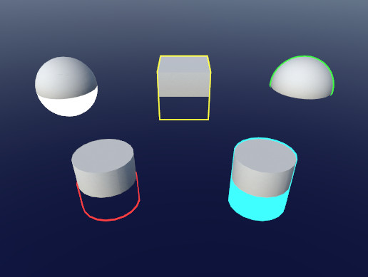
Hello guys, how would I go search for this? I want to edit transparency of intersection of this black cube and collider
You might get some results by searching for "cut out intersection"
Thank you, I'm not good at english, I didnt know what to search for
But cutting out a cube is harder than cutting out a sphere, especially if the cube is supposed to be able to rotate.
I'll see how it goes
With GPU Instancing and Sprite Renderers, only the instanced properties with equal value appear combined in the Frame Debugger? For example i set up a float called _Blend and i modify the value in Update via script of all sprites but at different speeds. All sprites that have _Blend = 1 are instanced, if they have _Blend = 0 are instanced, but if they have different values each like 0.1, 0.2, 0.5, 0.6 they are not instanced. Is this normal or means i'm doing something wrong?
@grand jolt The variable has to be set up and accessed in a specific way in the shader for it to support instancing. Maybe you're already doing that?
Yes i'm following the default sprites shader code and creating my own extra variable like this:
Try putting it in https://hatebin.com/
then i access at the fragment like this:
tex.rgb = lerp (grayscale, tex.rgb, UNITY_ACCESS_INSTANCED_PROP (PerDrawSprite, _Blend));
It's the default sprites shader, i just tried to add one instanced float property there.
Ah! Maybe is the way i change the value from the script!
I would like if someone can confirm that GPU Instancing can work with multiple Sprite Renderers even if the Instanced Property has different values on each.
does anyone know why I cant move background png image into this area (source image)
its saying node is not compatible with current render pipeline. Why?
@timid orbit change background Texture Type to Sprite (2D and UI)
ty ❤️
Make sure the URP asset is assigned under Project Settings -> Graphics
Thank you so much. I thought I just had to assign it in quality. I got confused
@wheat quail I'm confused with that as well tbh, bad UX
The ones under quality are meant to override the pipeline asset for each quality setting, but yeah, it's not exactly clear. It doesn't even have a prefix/label
good things to know
Heya guys, so i've made a sub-graph and duplicated it multiple times for different inputs, quick question:
I use a Time node in this sub-graph, obviously duplicating the graph also duplicates all the nodes within, would it be more performant to create an input for the time node and feed a single node into multiple sub-graphs? or is there no difference even if it's been duplicated more times?
or is routing multiple connections from the same node the same as just duplicating the node?
I doubt it will make much difference. The time node is just reading the built-in variables like _Time and _SinTime rather than doing any calculations
well when scripting I tend to feed off a single variable rather than creating vars on the fly, is that essentially what routing a single node in is doing?
trying to think of it like a script, multiple time nodes would be like doing:
1 = time.time
2 = time.time
3 = time.time etc
I guess so yeah, the compiler might optimise it anyway though
rather than
1 = time.time
use 1
use 1
use 1
hmmm, curious....would be good to know which way is better under the hood
i take it I would just need a float to route a Time node in?
The only optimization I can think of is to use less properties in favor of inline nodes but I assume that doesn't neccessarily apply to subgraphs since subgraph properties aren't actual properties - just inputs.
i think thats true unless it hits a ceiling (top shader), so if I'm using time and it's in a sub-graph i imagine that gets treated as a true property....
unless it's referenced in the properties bar..
Check the debug mode inspector
Each properties name is the reference listed underneath it in the blackboard
you can see all properties for the shader in the debug mode inspector
yeah, the Time node isnt getting referenced as a property as it's not referenced in the top shaders property list
If the worst comes to worst you can try both setups and then check the generated shader code for each
ok, yeah ill give it a shot
Wonders if 8 Sub-Graphs is a world record
XD
but are those subgraphs nested? 
thats inside a sub-graph rofl
probably a bunch, although not all of it goes all at the same time, and in the recent SG apparently IF nodes now only calculate one path instead of both, so it's nowhere near as bad as it would be in previous versions
I'm assuming some of that could get cut down with loops
it definately uses some heretical wizardry under the hood methinks
I've heard suggestions of using SG to create some boilerplate or template shader code which you can then edit afterward if it isn't performant. Although I am curious about what that graph is doing
it's a rare effect, most people wouldnt consider it, but it's designed to render a bunch of effects (like 6) on each side of a standard unity cube, all controllable per-face
Obviously 99.9% of shaders wouldnt need to do this so wouldnt be so bulky
it's effectively 6 effects x 6 sides
Couldn't you just make a cube out of six quads?
I'm honestly just shocked how many properties you have
Does anyone know of a good tutorial to learning how to code in it?
So far the tutorials are:
-5 hour tutorial live streams.
-20 minute tutorials that teach you 1% of it and then tell you to wait for the next tutorial. 4 years ago.
Oh no.
Brackeys doesn't have a tutorial on this.
Everything is going down!
AAAAAAA
@eager folio Depends what your doing, if you ever wanted to scale the object it's easier to scale one object instead of 6 quads in the appropriate ways
PizzaGamer is looking for a way to replace the process of making a texture2d and writing a colors array to it.
So basically using ComputeBuffer.SetData with a basic shader
I think it will write to a RenderTexture?
Hey! I'm using URP and I'm trying to control the lighting in my environment, but when I turn the lights down, my objects look like they glow and are untextured and stuff. The package I got is supposed to support URP, so I'm not sure what this issue is. Even with zero light, these objects look like this.
@grand jolt If they are all parented to the same object, you can just scale that object?
@fathom temple That looks like you have some degree of emission.
Though it also might be interaction with fog or something
What exactly is emission? I'm fairly new to this kinda stuff tbh
And I currently don't have any fog going on @eager folio
@fathom temple Emission is self illumination. It is set in the material. It also might be lighting from the scene, if you have any of that from the skybox or background
Ah, after some exploring, I found some emission settings in my materials and am tweaking them a bit.
Thanks for the lead @eager folio !
Emission is often added to vegetation to fake translucency.
I'm using HDRP and can't find a way to add emission to my particles (for more glowing effect).
HDRP in itself has no particle shaders, so I used the ones posted by Unity here:
https://forum.unity.com/threads/hdrp-particle-system-shaders.643840/
But there seems to be no option for increasing or adding emission.

Unity Forum
We are releasing some shaders to provide support for Particle Systems (lit and unlit) in HDRP.
This is not for use with the Visual Effect Graph.
The...
Ok I just realized I can edit these shader graph, so I'll try adding it
Hi all, not sure if this is a dumb question or not... I'm using Unity 2020.2.1f1 with URP... every shader graph tutorial in the universe starts out by saying "Start by creating a PBR Graph" ... except I don't seem to be able to. I've tried starting with one of URP's unlit shader presets, but there's no way to add a base map to that shader, which is driving me nuts... Is there anyone who can point me in a direction to solve either or both of these issues?
It has been changed in 2020.2! Along with a few other changes to things like the master node, PBR Graph has been renamed to Blank Shader Graph
So you're probably looking for Blank
Or I think there is Lit Graph under Shader > Universal Render Pipeline.
Blank Graph works to but then you have to configure the Graph Settings part
@hearty wasp @regal stag Thanks both of your for your responses - I was trying it with the URP Lit Graph and there's no Albedo option there either. I figured Base Color would do the job, but you can't map a texture input to it. I assume I have to chain a few nodes together to make it work, but... i don't know how to do it.
Base Color is what you want. You need to sample the texture with a Sample Texture 2D node
It was my understanding that Sample Texture 2D just takes the texture and takes a single average color and outputs that. Is that not the case? That does seem to be what happens when I do this. So for reference, what I'm trying to do right now is copy URP's default lit transparent shader for starters, so when I use the default shader with transparency on a plane, I get this
Using the Sample Texture 2D node, like so
I get this
Sorry for the spam, just wanted to show you what I was seeing.
As it turns out
This was the missing piece
No, it samples the texture at the given coords by the UV input. Which defaults to the mesh uv0 channel.
As you have found the Base Color is only the RGB part. For transpatency you need to set the Alpha too
Yeah, I feel really stupid about that in hindsight. Thanks so much for your help
Note that the previews in shader graph don't show the alpha part too, hence the solid dark red/brown result
@eager folio true enough, although your technically using 24 vertices to achieve the same effect as 8 vertices with a box
I did notice that, not really a huge deal, as long as it works now. Thanks again!
It's worth mentioning it might be more than 8 vertices for the box depending on its normals & uv coords. If it's flat shaded it will still be 24 verts
yeah, although the same effects would apply in both situations, so again it turns out the box is slightly better overall methinks
using normal maps increases vertices count??
Not normal maps but vertex normals. If it is flat shaded the normals point in different directions for each face, rather than an average like smooth shaded
oh ok, only using maps so far but yeah, vertex normals would
I imagine i'll run into stuff like that when i start Vertex Displacement effects soon
I mean, normal maps are defined in tangent space which also uses the vertex tangents and normals to create the tangent to world space conversion.
So it will still rely on the vertex normals
well kitty's original question was why not use 6 quads instead of a single box, so far I havent seen anything that suggests that would be better than using a box
BTW did they add the ability to see how performant these shaders are yet? I remember seeing something about it...
It would likely simplify the shader/graph in terms of size, and remove whatever check you are using to tell which face you're on
Like it would make your subgraphs have 1/6 of the inputs and same for properties with a quad based approach
And each face is only calculating what they need for that face, rather than all faces and throwing results out. That's what Branch nodes will end up doing.
in the newest version of SG apparently it only calculates a single path, not both
on branch nodes
but yeah, i see your overall point
Haven't heard that yet but I haven't used v10 much so that could be true. If it's still using a ternary operator I think it will calculate both sides though
i saw it a couple of times in those "whats new in Unity 2020.2" videos by various people, but they may have gotten it wrong, not entirely sure
is there a simple workflow for terrain and hdrp?
also for terrain, hdrp, and substance materials?
i understand sort of abstractly that it's possible, because i've seen demos of it online, to have a layered lit shader, and those layers are toggled in and out with the terrain's maps
@grand jolt If we are talking technical, not only are vertices duplicated wherever you have a 'hard' edge rather than a smooth one, but the unity cube is subdivided.
after consulting Cyan I ditched it anyways, but yeah your right @eager folio
Hey just a general question regarding shaders in games
Tons of games that have status effects like burns, poisons, etc. will apply a shader over the afflicted npc/player
So for example, if I run into fire, my character might turn red and ember-y accompanied by some particle effects
how are these games applying another shader over top of the existing material for that player/npc?
Do these materials that players/npc's use already have these shaders built-in?
Depends on the game. There are lots of ways to do it.
How can I invert a 2D sprite's normals in its shader code, but only when the sprite is flipped on the X axis?
I know it has something to do with viewDir but it's hard to find more info by googling
In unity, simplest way is to add a list of material in the mesh renderer. But you have to be careful with skinned mesh renderers.
From what I was seeing
There's mega shaders that have toggle-able effects like what I am talking about
So like all of your enemies could be using different materials, but all under the same shader that contains the ability to toggle on burn effects, or frozen effects
yeah, there is a keyword for that. something lke EnableKeyword
or something else as well. So if you toggle that, your effects will be applied as per the keywords
check this out as well : https://docs.unity3d.com/Manual/SL-MultipleProgramVariants.html

yeah, shaderfeature and keywords etc...
also, dear devs! I need some suggestion from you (if possible). I am rendering geometry in the geometry shader. In the shadow caster pass, I have added the mesh as well. Now to receive shadows, should I add another pass? what would be more optimized way?
nvm, added the shadow casting and receiving ...
this may seem like a dumb question but i have been doing shaders for a while just like messing around in shadergraph, but i always get stuck with trying to figure out how to layer shaders similar to how layers work in photoshop. Because for a while i have just been adding on and using replace colour but it had its limitations or the actual graph becomes very large for something i feel is so simple. So basically what im asking do shaders have the ability to overlay layers, as you would in photoshop and how would i do that?
Do you mean layering shaders or layering textures? Usually when we code shaders, there is a concept of passes that we use. eg : In a blur shader, we can do a horizontal blur in one pass(layer), then take its output and perform a vertical blur in another pass (layer) and that is how we get the final output
but if its only textures you want to overlay, then just apply the logic in one pass itself
im trying to find one of my terrain shaders
layering texture i feel it more so relates too
just going to grab an image of how i fixed the problem in the graph
are you coding or using a graph?
ohh okay, sorry m not the right person, would call in other devs to answer 🙂
thats all good
this is what i have done
this is what i have been doing to try an layer stuff just change the colours, so when i next select replace colour it doesnt replace the area i want to keep
Hello, I am trying to simulate directional (sun) shadows in top down 2D game. So far I have managed to use geometry shader to extrude sprites and cast shadow, but I can't find a way for the extruded sprites to receive shadows. I am not good at writing shaders, googled some solutions, but all of them produce pink shader, I think some shaders are not compatible with URP?. Can someone help?
Also is it possible to write such shader with Shader Graph? That way it would be much easier for me to edit shader
P.S. I am using Universal Render Pipeline.
Extrude shader https://pastebin.com/sErBwa0E
Shader demonstration https://www.youtube.com/watch?v=lQgUzBGlVtE
Pastebin
Pastebin.com is the number one paste tool since 2002. Pastebin is a website where you can store text online for a set period of time.

This looks like a really cool problem! How do you intend the sprites should look when shadowed? To me it makes sense that the sprites don't have shadow, because you are only seeing the top illuminated bit
or do you mean in places like the crates next to the walls you would expect to see a shadow?
yes, wall would cast a shadow on a crate. It should look something like
I do have another shader which can cast and receive shadows from a sprite, but it does not have any "height" so it looks like this
in 3D view
Sprite shadow shader is written with Shader Graph, but I don't know how to extrude vertex along normals with Shader Graph, combination of both shaders would be perfect. I could just use 3D cubes, but then I can't use tilemaps for easy map editing
if what you are trying to do is giving the terrain color based on height or normal direction you could just sample a texture as a gradient for your height and normal colors
i used normal direction
the shader works for what i want just seems stupid how i did it
like normal.y could be uv.x for the sample node, you remap that to be between 0 and 1 instead of -1 and 1 (add 1 multiply by 0.5)
yes it is weird
no clue what you did there and I don't even want to find it out
oh yeah true could do that
i think i grabbed the normal y
and have just done the most scuffed thing to separate layers of it
my initial question i was wondering if something like layers existed in shadergraph?
I don't get what you mean by layers
like in photoshop how you have the layers
then you can display the ones underneath, with a transparent layer on top
more so like a mask
You mainly do layers through masks + lerp/blend. Something like this
ohh that would have worked so well
but also my question is im going to try and sketch it out cause i feel like i cant explain
Lets say i have this blue square, and i have this black circle
how would i place the black circle on the blue square without the white background?
without making the white background blue
by making the white background transparent, with like an add node or something
The black/white circle is basically already a "mask", so you put it into the T input on a Lerp node and set A as the circle colour and B as the background colour
Blend node with Overwrite mode is also same thing as Lerp
im confused, isnt the T input time on the lerp node?
e.g.
huh thats sick
T is a value between 0 and 1 used to interpolate the value. It's sometimes used to interpolate though time but can also work in space. When T=0 it outputs A, and T=1 it outputs B.
(T can also be outside the 0-1 range and it will extrapolate the colours. If that isn't desired, you can clamp the T value with a Saturate node if it's outside the 0-1 range).
It's just labelled as T, but any value would do
Basically it's render A in the white area, and B on the black, OVER whichever mask
In the cases above they are just pure black/white, but it also works with gradients. e.g.
So this is the basic idea behind masking in computer programs?
No worries, that's a good example to show it works with textures as well as colours. They're both Vector4 / RGBA
Hello ! I actually have something like that in my shader graph shader
May you know how to add the possibility to rotate my texture too ?
I did it like that, inputing my vectore 4 in the tiling offset form the uv selection
Found it
@jagged quail I dunno how to fix your problem but I just wanted to say that that shader is awesome! I hadn't even thought of trying that.
Is it possible to make a UV-map material have certain parts that have bloom, while the rest don’t? (Eg., a face’s eyes glow, while the rest of the face does not)
It's possible that this is literally an unsolvable problem: does anyone know a fast formulation for N-dimensional fractal-ish noise that will let me compute the integral over the line between two points?
You can do it with an emission map
I want to displace points on a sphere according to a texture. So the higher the grayscale number the higher the displacement. How would I go about doing this?
Example:
Normal mapping isn't good enough, I need the points to physically move
If your sphere is high poly enough, check for vertex displacement.
alright, thanks

using urp. created a simple alpha clip shader graph. When the front of texture isnt facing the light, both sides od the texture are dark... what do I need to add to the shadergraph to make the planes receive lighting more realistically?
@wheat quail You could change the Vertex Normal to always face the sun. The lighting calculation will then always apply full brightness for each pixel. Not sure if you can call that more realistic, but it will probably look better.
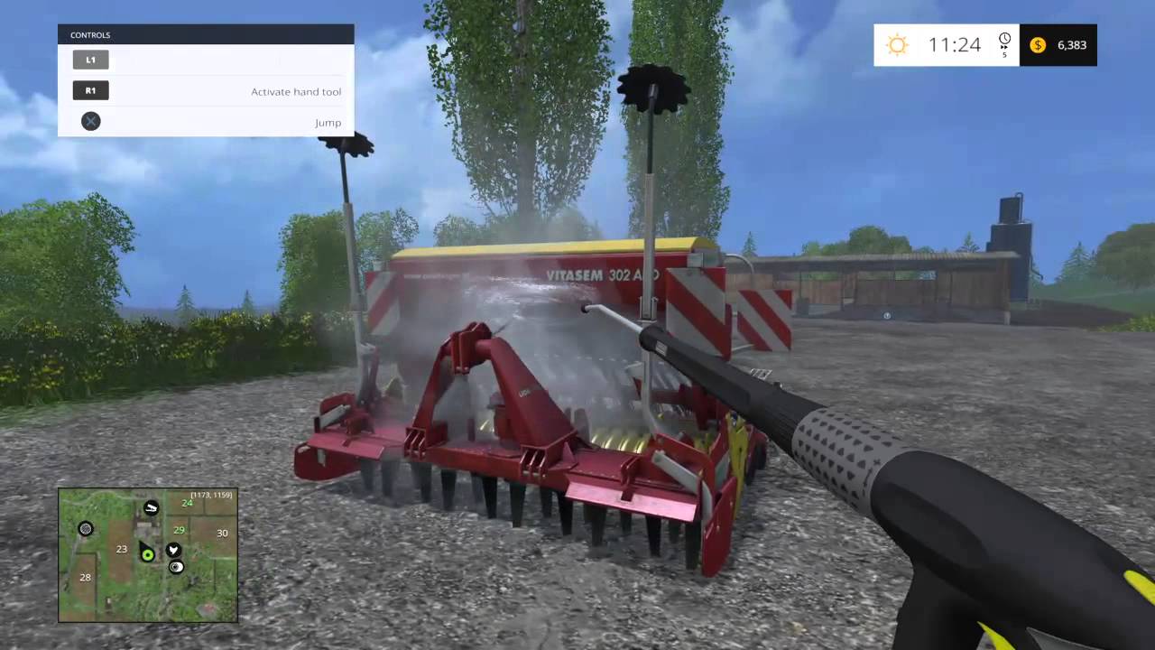
hey, does anyone here know much about shaders, materials, textures? i am looking to apply a dirty texture to a model and using a raycast, start to fade the opacity of the texture, is this possible, if not how could i go about it? thanks
i have put a post of unity forums but looking for some help here? https://forum.unity.com/threads/how-to-jet-wash-vehicle-objects-like-farm-sim.1037071/
Unity Forum
Hi,
I am looking for some advice for a prototype/concept!
I want to replicate the jet washing mode of Farm Simulator, the tractor and trailers get...
i thought i may be able to create a tracktor in blender, then either UV unwrap or paint in blender a texture for LOW, MEDIUM.HIGH dirt (let's say), then a raycast can hit certain layers of the model and every few seconds of contact can turn down the opacity and then change from HIGH to MEDIUM, MEDIUM to LOW, is this possible?
You would use a mask texture to add/remove dirt texture overlay. Should be easy enough tutorial to find.
a mask texture, awesome i will look into that now, thanks
Not sure on the best way to provide information to the shader to draw on the mask though, never done something like that.
It could have built-in stamp to draw on it with perhaps.
And UVs must be very consistent in scale for this to work properly, over entire model.
i have probably got my terminology wrong here but is it possible to create a material (to apply to the tractor door) that has a texture and a base color (albedo?) that i can turn down 10% of the texture (with the dirt) with code?
You would still need a mask and draw on the mask
is the mask to create the texture so that it's semi transparent, ie black for clear and white for full?
or am i being dumb here?
but you are suggesting the mask with regards to creating the texture right? so i have the dirt drawn onto a masked image and then apply that as the texture to a part of my model (say the door) and the original materials albedo shines through the part of the texture that is not filled in right?
I was linked this recently : https://www.youtube.com/watch?v=c7HBxBfCsas
The first part of it goes through a method they used to create & draw on the mask texture. The example is more like painting, but the mask could easily be used to do the opposite and remove a layer of dirt or whatever.
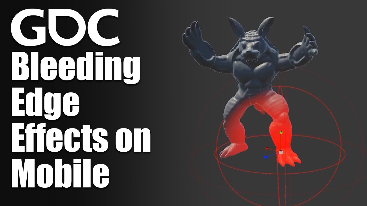
In this 2020 GDC Virtual Talk, Level Ex's Andy Saia break down seemingly complicated effects into simple steps providing you everything you'll need to implement effects like these to solve a wide variety of VFX problems in mobile games and other platforms.
Join the GDC mailing list: http://www.gdconf.com/subscribe
Follow GDC on Twitter: https...
Basically everything between 3:00 to 10:00
excellent thanks cyan - i will give it a watch now - hopefully it will point me in the right direction
Do you have any ambient light on?
I dont think ambient light will work because I put in a directional light in my scene and it removes shadows from everything else
and actually makes the grass even darker 🤷♂️
GAPH?
oh, so it's not a typo of GRAPH?
no
does anyone know a way to write to the depth buffer in an OnRenderImage full screen shader? (with the [ImageEffectOpaque] queue modifier thingie if that makes any difference)
@mortal forge you should use the lit tesselation shader in hdrp
@loud canyon can i ask why
@jagged quail you should probably use 3d cubes, they are compatible with tilemaps
Can i export blender shader to unity?
@loud canyon Anything that you draw that has ZWrite On in the shader will write its depth to the depth buffer
Hey! In HDRP, I'm trying to do a creature with anisotropic fur as well as translucent ears. But in the Lit shader, anisotropy and translucency are two different modes and can't be used at the same time. Is there any way to use those at the same time?
You can combine those feature by using the stack lit shader / master node (depending on the HDRP version).
Bear in mind that it will be heavier.
Thanks a lot! It's a cinematic project, so the low performance is ok!
Hi, is there a way to use compute shader to read -> edit -> write to a Render Texture?
I know how to write to a render texture using compute shader but I'm getting stuck at the read part.
Can anyone help please. 😕
@lusty badger It's a bit awkward to read and write to the same texture at the same time, but certain texture formats on modern hardware does allow it.
@low lichen So if I used an input texture to run it through the compute shader saving the result to output texture and then putting the output to input that could work?
Yes
Reading a texture is pretty simple: (writing this from memory, doesn't necessarily compile)
#pragma kernel CSMain

Texture2D<float4> _InputTexture;
RWTexture2D<float4> _OutputTexture;

[numthread(8,8,8)]
void CSMain(uint3 id : SV_DispatchThreadID)
{
    _OutputTexture[id.xy] = _InputTexture[id];
}
So if i need a highlight around items in a FPS, 3D with HDRP environment, what is my solution?
Have looked at many different guides but i dont get any to work, is there any "easy solution"
Like when i look at a object it gets kinda border
@livid gazelle
GitHub
A bunch of custom passes made for HDRP. Contribute to alelievr/HDRP-Custom-Passes development by creating an account on GitHub.
Hello, I have a flipped sphere (so only the inside renders).
I'd like to sample a cube map from its fragments, but their direction would have to be the normals the front face would have.
Somehow I'm stuck trying to do this. Just mirroring the object space normal isn't enough.
Weirdly, view to object does... the same?!
Oh. I figured it out! I tried your approach with swapping textures and it didn't run really well. Before I tried just getting info straight from the RWTexture2D and was getting an error and couldn't figure out why for last 30 mins. Then I found out that VS Code made a copy of the file I was editing when I moved it somewhere else so I was fixing a different file the whole time without changing anything. -_-
I just get the data straight from _OutputTexture, edit it an save it back to the _OutputTexture and it's running smooth as butter. 🙂
I think the circle case doesn't work for the sphere case, but why. Probably because this is in 3d and with perspective projection.
But I transformed the view direction into object space.
hey can someone help me? i'm kinda new and im using a model from the assets store, the weird thing is that the model have red lines on it, in the read me.txt it says to mess with shaders, outline thickness and things like that, anyone can help?
Hello can someone tell me a good tutorial for a Toon shader?
anyone know of any documentation for these surfgrad subgraphs? They are very useful and I know Mixture uses them as well
https://github.com/mmikk/Surfgrad-Framework-Unity-Shadergraph
https://blogs.unity3d.com/2019/11/20/normal-map-compositing-using-the-surface-gradient-framework-in-shader-graph/

GitHub
This is a sample scene made with Unity which includes a folder of subgraphs, for shadergraph, of the surface gradient based bump mapping framework. This is a new framework which allows you to do la...

Unity Technologies Blog
A recent Unity Labs paper introduces a new framework for blending normal maps that is easy and intuitive for both technical artists and graphics engineers. This approach overcomes several limitations of traditional methods. Since the introduction of normal mapping in real-time computer graphics, combining or blending normal maps in a mathematica...
hi does anyone know how to do falling sand simulations with compute shaders
Is it possible to create custom editors for shader graph shaders?
Ya, but I'm trying to write custom info, not just a screenspace quad
integrating my raymarched world with post-processing effects
I ended up figuring it out (if anyone else wants to know), it's through the literally undocumented out SV_Depth
took an day, but now it sorta works 😄
Actually - on that - does anyone know the most efficient way to read a single pixel from the depth buffer onto the cpu? Cloning the entire texture feels a tad excessive (but might be necessary if there's no way to target a compute shader or something)
Unity 5 have shader editor?
@wraith dune I assume you mean a visual node based editor, as opposed to a text editor, and no Unity 5 does not have an included shader editor.
There might be some third party assets that still support Unity 5
But you will probably make those asset creators cry at night
Yes, you can define the custom editor class in the shadergraph settings
@azure geyser if you're interested, you could check this out
allows you to use markdown-style syntax in shadergraph blackboard which will generate an appropriate shader gui, but it's basically the same system that remy mentioned with the custom editor class, just automated
Thanks @devout quarry for sharing this, very helpfull tool.
I also discovered how to use asmref now 😄
Thanks guys, really appreciate it!
hi i have been trying to make a parallel falling sand simulation but even with very simple code it creates race conditions
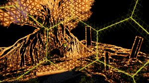
I'm beginner in unity and I dont know where to start to create this effect of fog sphere. Can you suggest an idea how to do this
Or maybe this is several particle systems with noise? Or shaders?
I think it's a particle system
But i dont know how do this with one PS
Maybe a lot of particles with some noise?
Seems more to be "big" particles that have a texture similar to what you can see in the second screenshot, blended together using additive blending.
And maybe other more disk shaped ones
And how to make or find such textures in general. I believe that several such textures are needed, which will mix with each other in the particle system.
Well, some art skills and an image editing/painting tool
Do you think these textures are suitable for a particle system?
Yes
Hey I'm working on a voxel game, and I don't know how to get rid of curves in distant textures. Bilinear filtering gets rid of it, but makes the textures blurry up close, and Point makes the textures look good close, but curvy far away. Is there a shader or something to combine Bilinear filtering and point filtering?
@indigo grove Usually, you would use mip mapping to reduce this
It also happens to improve performance, so it's a win/win
Is there an easy way to generate mip maps a texture atlas?
or do I have to code it myself
The texture is generated at runtime?
A texture atlas for all of the textures is
This method might do it
https://docs.unity3d.com/ScriptReference/Texture.GenerateAllMips.html
that's not a method
but I did set the texture to make mip maps in the constructor
Doesn't look like it does muchh
I think as soon as you call Apply() to upload the texture to the GPU, it will generate the mip maps based on the mipmapCount
Ah
But I'm not sure where you set the mip map count, it seems to be read only
you do it in the constructor
new to shader graph... i accidently pressed something and now the parameter window from shader graph view is missing
can any1 tell how to make it visible
It's referred to as the "Blackboard", there's a button on the top bar, on the right-ish to toggle it
@low lichen Thanks! But now I have a new problem...
hmmmmm
@indigo grove How many mips did you tell it to make?
I told it to make 2, but it still generates 5
I'm trying to see if I can change the mipmap count of a texture right now
Maybe this is too broad, but I'm looking to create a nice selection effect for my tiles in a game, however a basic fresnel shader graph doesn't work very well on cube/cuboid shapes
I mean it works how a fresnel should but you get what I mean
Can anyone link me to a shadergraph tutorial with some kind of outline, highlight effect that would suite>
@low lichen is there a way to change the bluriness, or make it further away
I found this https://www.unity3dtips.com/unity-fix-blurry-textures-on-mipmap/ but it doesnt work on generated textures
How to adjust Unity blurry textures on mipmaps to make textures less blurry at a distance without disabling mipmaps using the texture importer mipmap bias.
How could I pass these UVs into shader graph?
https://youtu.be/2fgTsmVE8Gk

Moving along from our previous 2D checkerboard example, we move on to changing our models 2D UV coordinates into 3D UVW coordinates, that are recalculated in world space as the object is moved around the viewport in editor mode inside the Unity 3D engine. In the next video, we will extend our 2D checkerboard texture into 3D space.
Thanks for wa...
Why... does unity not provide a (main) Light direction node in SRP Shadergraph?
And every sample I use doesn't seem to work right now, usually because it's from 2019 BCE or something

GitHub
Some custom lighting functions/sub-graphs for Shader Graph, Universal Render Pipeline - Cyanilux/URP_ShaderGraphCustomLighting
There ya go
Thanks
Should be the same. Mesh.SetUVs(0, ...) updates the UV0 channel of the mesh. That can be accessed in shader graph via the UV node, channel 0. Which is also the default UVs that many nodes use.
I think this might be the same result as the Position node set to World space though?
When I use the Position node in world space it offsets my procedural textures by a fair bit. I've been able to get it to work by remapping position but I wanted to see if this method produced different results
Is it possible to define a color array in a shader's properties and have it serialize and be available in the inspector?
Not through properties, no. At least not that I'm aware of.
would this be the group to ask about compute shaders?
I have a simulation coded with c# jobs that I'm considering porting to a compute shader, but I don't know how to write compute shaders. I have the parallelism problems down, I just need a starting point.
but maybe before I go down that route, it makes sense to ask a few questions related to whether or not it would actually be worth doing:
- I'm planning on passing this information over to rendering shaders to visualize the data, in the form of an array of floats. can you pass information directly from compute shaders to rendering shaders like that or does it have to be copied to some cpu buffer and then back to the gpu?
How do I do custom amount of mipmap levels? Unity always forces my textures to render with 5 mipmap levels, resulting in black textures (the textures are 16x16)...
- would it be reasonable to copy back an arbitrarily large array of floats back to the cpu for use in game simulation, or will I eventually hit diminishing returns where it would be faster to do it on the cpu because of the time it takes to copy the array?
...just those two
but yeah, once I get those two questions answered, any good up to date learning resources you guys know of for writing compute shaders?
You can likely get an array/list visible in the inspector via a custom ShaderGUI though. But where to serialize it, not sure. I guess just though Material.GetColorArray and Material.SetColorArray.
According to a forum post from 2016 that doesn't serialize
Ah right. They only work at runtime :\
Maybe it would be possible to create a ScriptableObject (and save it in assets) or something in the ShaderGUI to hold that data?
Yeah thats been considered just wanted a cleaner approach, we tried subclassing material but that did not work at all
And perhaps we did something wrong but donno what
can we add emmision to unlit shader?
Sure.
Just add it.
(as in, add the emission color value to your final color value)
How do I make a Texture asset have a certain amount of mipmap levels? (e.g. how to change the mipMapCount of an asset)
Hi,I don't know if someone could help me with my problem, I am a beginner on the shader graph. I have make a cel shading with shader graph thank to a tuto but this tuto they doesn't sense a point light in HLSL code. Is it possible to take a additional light in the same code where I'm getting main light? Version 2019.4.17 Urp
@soft hollow Yes, it is possible. There are functions similar to GetMainLight that let you loop through all the additional lights.
I think there's one function to get the number of additional lights and another function to get an additional light based on an index.
@soft hollow These functions are all defined here:
https://github.com/Unity-Technologies/Graphics/blob/master/com.unity.render-pipelines.universal/ShaderLibrary/Lighting.hlsl
It would probably look something like this:
int lightCount = GetAdditionalLightsCount();
for (int i = 0; i < lightCount; i++)
{
    Light additionalLight = GetAdditionalLight(i, worldPosition);
    // do something.
}
GetAdditionalLight also needs a world position, which would be the world position of the current fragment/pixel.
hello guys I just installed the new version of LW rendering that is Univeral Pipeline Renderer but I can't see the properties like before, to change the values in, anyone knows why?
Look in the "node settings" tab of the "graph inspector"
@amber saffron its empty :S
You need to have one of the parameters selected
ah I see, when u click on a property it displays it there
thanks a lot, i was becoming crazy searching on internet xD
i did this effect on a shader but seems like my sphere its splited in two, anyone knows why?
UV seam
what is uv seam?
UV are also called texture coordinates. It "tells" how a texture is applied on a mesh
And your using this for the swirl (UV input)
And, by default, on a sphere, there is a seam. Image wrapping a rectangle around a globe
Sorry i'm new on this and i can't understand what i'm doing wrong with this
Imagine that each of the square previews are images wrapped on a sphere. On the twirl one, you can clearly see that the left of the image doesn't match with the right. That's where the seam is visible, because that where the image sides match to wrap arround the sphere.
Similar at the poles.
i see
You'll be able to see it if you output the Twirl result as the Base Color too
i have a neon silhouette shader i got of the internet, but the silhouette scale is relative to the camera, anyone who knows how shaders works so i can fix it?
https://pastebin.com/e5iRpmXy
Pastebin
Pastebin.com is the number one paste tool since 2002. Pastebin is a website where you can store text online for a set period of time.
@regal stag yea i saw it
seems like I have to do something for an sphere instead of a plane
On vulkan or directX, are cube map samplers in Unity done in hardware? Or is the lookup software?
and then, how are cube maps compressed; is it just the one texture? (I suppose legacy cube map assets stitch their constituents together too)
I want a cube map that's just 2 sides as caps (to blend that with a cylindrical mapping). Looking for a way that's not gonna cost me an arm and a leg shader wise.
Cylindrical cube maps are still converted to cube maps internally, too, right?
yes that becomes an issue though there is AsyncGPUReadback if you can afford a frame or two of latency for the GPU to GPU transfer to occur rather than stalling the main frame to wait for it to complete by just using GetData. forewarning that the AsyncGPUReadback API is pretty barebones. it handles scheduling, but it's up to you to package up your data into contiguous data frame buffers for transfer and deal with FIFO queueing (unless you are fine with receiving and processing multiple data frames within a single render frame, are okay with simply dropping extraneous data frames when more than one is received in a single render frame, or don't care if your async data frames arrive out of order.) though the Collections package has a NativeQueue that may help and async / await in C# has AsyncQueue though I haven't tried either of them myself
cubemaps are stored and processed similar to any other texture, so there is some fixed function raster and/or texture hardware involved that helps with interpolation and mip maps if applicable.
not sure what compression but presumably some sort of layout in a Texture2D or a Texture2DArray. I know they can be compressed in Unity these days anyway. But it seems to be able to support compression and some other features, you need to convert any non Cubmaps assets to Cubemap first before importing? see this excerpt:
Note that it is preferred to create cubemaps using the Cubemap texture import type (see above) - this way cubemap texture data can be compressed; edge fixups and glossy reflection convolution be performed; and HDR
cubemaps are supported.
from this doc:
https://docs.unity3d.com/Manual/class-Cubemap.html
yeah seems like it, the documentation linked above says (after mentioning cylindrical and other import types)
When imported, a cubemap is produced which can be used for skyboxes and reflections
Hi everyone!
Is it possible to create shader that I can apply to a material in URP that looks like this? I mean the yellow outline.
I am working on a project with SteamVR and I had this shader in the default rendering pipeline but since I changed to URP the material that ppl from valve left is much, much worse. I've looked for some option around the internet but I couldn't find any options that would just work with a material, mostly some shenanigans with second camera.

Unity Learn
In this tutorial, you will learn how to use custom render passes to render a toon outline post processing effect on selected objects
Well, I am gonna check it out. Thank you kind sir 😄
I would recommend the technique used by this asset.
https://assetstore.unity.com/packages/tools/particles-effects/quick-outline-115488
Use the Quick Outline tool for your next project. Find this and more particle & effect tools on the Unity Asset Store.
It probably doesn't work in URP out of the box, but should only be minor shader changes since it's unlit.
@low lichen maybe able to use it for reference though. to combine these two approaches
This asset does the basic hull inflate, but fixes the face separation problem on meshes like cubes by adding an extra vertex attribute to the meshes that tells each vertex which direction they should inflate, instead of just following the normal.
So it requires a script on each outlined object, which modifies the mesh
It could do it better now by using MeshRenderer.additionalVertexStreams instead of duplicating the mesh
@low lichen ah that sounds like it results in a sharper more perfect outline, if that matters
Yeah and it automatically supports everything you can think of, MSAA, post processing, since it's just a regular unlit mesh.
@low lichen it seems like this URP approach on Unity Learn is similar in some ways
The Shader works by inverting the normals of a Mesh (an operation that subsequently makes it no longer affected by lights), extruding them beyond the Mesh by some offset, then colorizing them by a user-defined RGB color.
trade off being like you said it may have separation artifacts but also is going to be more performant and work on skinned mesh renderers, etc
also seems like something that tesselation or compute shaders could help with making more performant and flexible... or eventually mesh shaders once they are available lol
Well the nice thing about that technique is that the smoothed normals only have to be calculated once, and can be prebaked in the editor and loaded at runtime. Compute shader might be able to crunch through the numbers faster, but if it's in the editor and just once, it's not so big a deal if it takes a second.
I'm not sure if Quick Outline works on skinned meshes actually. You'd have to store the smooth normal in tangent space rather than object space I imagine, don't think it's doing that.
Thanks @low lichen I will check that one too 🙂
hey anybody know any good shaders
@fleet glade Do you know any good C# scripts?
lol
@fleet glade just scroll up and read this channel's message history, it's chock full of good shaders and ideas
or if you have something specific you're looking for, feel free to ask about that. some form of https://dontasktoask.com

does vfx graph support shadows?
i am not getting any cast
from the default asset
i checked the box "Casts shadows"
default asset meaning the one it creates
everything else casts shadows fine
question 2 - does it matter it's a DXR enabled scene?
ok
hmm possibly. I don't believe vfx graph works with raytracing yet, but i know it is on the roadmap
@shrewd crag check out the pinned messages on the #✨┃vfx-and-particles channel if you want to check out the roadmap for more info on that
where vfx graph casts shadows on other gometry
i see that people conflate "casts shadows onitself" versus "casts shadows on other geometry"
@shrewd crag i know cast shadows for vfx graph outputs that have that property works without raytracing in HDRP, i use them all the time
the vfx graph primitives cast shadows on other objects and themselves
i got casting on themselves to work...
very close
okay i figured it out
Ray Traced Shadows checked in the light --> no shadows
unchecked --> yes shadows
solution: two lights
is there a way in hdrp to light link / shadow link?
@shrewd crag nice yeah i was wondering if some hybrid method would work. the line is a bit murky but still getting a bit off topic for shaders here but feel free to hit up #✨┃vfx-and-particles for vfx graph related topics i hang out in there often. and #archived-hdrp which is probably the best channel for DXR / raytracing specific or cross cutting issues with Graphics / SRP packages like this.
how about Force No Motion for canvases?
is this possible somehow
disabling motion vector for worldspace canvas
okay
unbelievably, placing 3d objects behind the canvas and turning off motion blur for them
does it
it doesn't look perfect but it does the job
Okay so I am curious about how to work around the "maximum ps_4_0 sampler register index (16) exceeded" thing in shadergraph, anyone know how i could go about this?
It's an interesting thing I havent seen before, mainly becuase i havent used that many textures before
I looked on google to see if anyone had asked this before, and it seems to be only script related instances
@sonic bear The script related instances still apply to you because your shader graph is converted into code eventually.
Yeah I know, I need to figure out how to do the same thing without using 16 samplers
@sonic bear It's possible to share samplers for multiple textures. I'm not sure if that's possible in Shader Graph, but shader graph does separate sampler states from textures.
@low lichen I am trying to figure out how to do that as shadergraph allows you to write custom functions/nodes
I am looking at this thing on the forum but given I have no idea about how to code shaders I cannot tell if it would work or not
(link, but screenshot of what i am talking about is included https://forum.unity.com/threads/maximum-ps_5_0-sampler-register-index.562867/ )
Unity Forum
so seeing this error in my shadergraph using LWRP,I’m guessing I’ve hit a limit on how many textures I can use in my shader. I’m just staring to work...
well that was two hours of my life wasted, all you have to do is just use the same sampler state node to fix it
I am trying to make a shiny reflective floor on my scene
I have a reflection probe and light probes
you might want to lookup planar reflections, depending on which render pipeline you are using there are solutions for each some need more work than others
Is Shader.SetGlobalX the only way to communicate with a shader from C#?
coincidentally I just came across this myself on github too while I was just about to get back into shaderGUI, but I have a question maybe you could answer if you don't mind - if I were to use this tool to do my shaderGUI does it actually still work when I give my shader to someone else via unity package, even if they don't have this Shadergraph Markdown tool?
cause I kind of took this bit here as that it won't work unless you actually have shadergraph markdown in your project
It should work fine as the tool doesn't alter the graph or it's saved data in any way - only how it's displayed Well, you need to set up a few properties but that's just like a Vector1 or something already included in shader graph, nothing extra. (In it's current version at least).
That part is saying that, if you don't have the package installed then you just have some properties that will do nothing
So the GUI actually won't work anymore if I set it up with this, and then get this shader to someone else?
Sorry my first explanation was a little vague
If they don't have the package it'll likely give a warning that it can't find the ShaderGUI and just show the regular one. At least I hope that's the case
Yeah, it'll show a warning like "Could not create a custom UI for the shader 'shader name' .. etc" and show the properties how it would without the package. You can then stop that warning by clearing the Custom GUI field in the graph.
hm, I see, thank you for answering
I have a normal Vector in object space (spherical object).
I'd like to look up a cylindrical map with this. How could I do it?
If I use atan2 to turn the XZ axis into U, I get gaps at the edges of the definition space.
I don't want to look up a cubemap; unless cylindrical cube map is what it is in hardware (any proofs? or does unity convert a cylindrical layout map into a 6 sided layout?)
The point is, I am blending the caps of the sphere with a planar projection already, so I would like to avoid empty huge textures (i.e. a cube map with transparent top and bottom, etc.)
I can't use UVs from the mesh because it's the UV of the wrong fragment (backface of the object); and actually I would rather use a quad instead of a sphere mesh, it's for a volumetric sphere.
Hmmm
Anyone know a simple way to find all materials using x shader in the Project window?
So for my unit sphere in object space, phi=y+0.5pi; lambda=x+0.5
but that's weird.
const vec2 invAtan = vec2(0.1591, 0.3183);
vec2 SampleSphericalMap(vec3 direction)
{
    vec2 uv = vec2(atan(direction.z, direction.x), asin(direction.y));
    uv *= invAtan;
    uv += 0.5;
    return uv;
}
perhaps something along these lines.
In shader graph, does multiplying a Vector3 with a matrix apply the matrix transform? I'm a bit new to matrix stuff so sorry if I've got the terminology wrong. But I mean, in HLSL you have the mul() function, which you can use to transform a Vector with a matrix. Does the multiply node do the same thing?
Does anyone know how to make a lit shader that has a part that is unlit? I’m making an outline shader to highlight objects, and i want it to work in a dark room, but the object itself would be dark if there is no lights.. shader graph plz 🙂
if there is no light, lit or unlit should give same results although there can be things which affect this.
If there is no light, a lit shader is black. I want the sprite black, but it’s outlines fully bright using hdr color
treat it like emission map
@unique oar Yes, Shader Graph will change the behavior of the Multiply node if one of the inputs is a matrix
https://docs.unity3d.com/Packages/com.unity.shadergraph@6.9/manual/Multiply-Node.html
@thick fulcrum aha, thanks! 🙂
how do I pass the surface normal into a surf function?
hi ! why can't we change the variables name anymore in shader graph ?
Pretty inconvenient to use the default "Vector1_7015e114865445a68da16608693a9fca"
I can't even set variables to the "slider" mode in Unity's UI
Check node settings menu @heavy belfry ?
Oh alright didn't know this menu existed
Thanks !
I still prefer the way it used to be tho, what's the point of this menu ?
I don't know, keep the blackboard less cluttered maybe? Idk , I preferred the old blackboard so you could create property -> set it up without having to switch UI
Does anyone have any info/experience with customrendertexture performance? I'm investigating splitting up a larger shader with way too many features into smaller pieces that can be combined but some initial (very unscientific) tests weren't promising as far as scalability goes.
Most of the things I'm looking to do with them do require realtime and per frame running of the customrendertexture. Generally stuff for animating textures.
I'm very new to shaders and i'm not really sure what i should be searching for to figure out how to achieve this. Can anyone point me in the right direction?
If i have 2 models, the character and the gun, I'm trying to use the character as a mask, so that the only thing that is rendered is the gun, with where the character overlaps being cut out. Essentially the opposite of this second image.
how would i go about creating a shader in shadergraph that randomizes vertex color ? im using the URP and cant find a way to change vertex color .
I'd look into Stencil shaders. e.g. Render the character writing a value to the stencil buffer, then render the gun testing against the same value.
https://www.ronja-tutorials.com/2018/08/18/stencil-buffers.html
https://docs.unity3d.com/Manual/SL-Stencil.html
A shader doesn't set the vertex colour, it's only used an input. You'd have to change the colors array on the Mesh via C#. https://docs.unity3d.com/ScriptReference/Mesh.SetColors.html
If you're looking to change the whole object to the same colour, I'd probably just use a Color property instead of setting a per-vertex colour though. Can set that through C# with material.SetColor. https://docs.unity3d.com/ScriptReference/Material.SetColor.html
(And for actually obtaining a random colour, maybe look at Random.ColorHSV) https://docs.unity3d.com/ScriptReference/Random.ColorHSV.html
@regal stag thanks!
ah i see, thank you.
Are shaders for grass more performant than using placed grass prefabs, or is it just more convenient? Using HDRP.
I'm clicking on the color to try and change it but a color chart isnt popping up. How do I make the color chart pop up?
Clicking on the colour usually does make it appear, but I know a few others have had issues with it. I'd try restarting Unity. If that doesn't fix it, might be a bug with that Unity version / URP version, so I'd try updating if possible.
thx
Using shadergraph, how would I go about having a border of equal width around a scaled quad?
Holding shift and clicking on the color open it up. Can;t be bothered upgrading to new version of unity atm
You can use the Object node to obtain the scaling of the mesh/quad. Then use it like so :
Ha perfect! Thank you
UVs go from 0-1, so 1 is full width/height. The graph above is using 1 - spacing as the width/height of the Rectangle, but that spacing is also divided by the scale to stop it just stretching it out.
That's some dark magic to me lmao
Ahh, I see. Didn't know there was official documentation for Shader Graph. Thank you!
Can anyone pls tell me how to create a flat shading shader graph in unity
For terrain
@storm sparrow AFAIK that's impossible without writing your own way of interpreting lighting. Normals are determined per-vertex, not per-face
Terrain doesn't split vertices like all the flat-shaded objects you see
Plus that would look really strange anyway, since terrain implements an LOD system, so if you move too far away from an area, you would see its lighting suddenly change
Ok thanks
guys
i dont work with post processing much
how do u make that the post process volume only effects one object?
like lets say i only wanted the effect to apple on the floor
or background
hey guys, imported the free unity particle pack and everything is pink, why is this?
@lime thistle renderpipeline-mismatch? Maybe you're using URP and the particle system is meant for default renderer?
updating what?
I'm trying to do a "text" shader- but can't seem to get the texture- I always end up with a single color rectangle. the size of the rectangle looks correct- it's just the sampling of the fonts texture I don't see. I even created a monobehavior that calls font.RequestCharactersInTexture but still- no texture showing up. The reference to the texture in my shader graph is called "_MainTex". This is unlit HDRP shadergraph I'm using. Any ideas?
anyone know how I might add a specular highlight toggle via shader graph like the standard unlit shader has?
What does the toggle do? Just turning it on/off?
yep
The keyword for toggling it would be _SPECULARHIGHLIGHTS_OFF if you're using PBR/Lit, in URP at least (not sure about HDRP). Annoyingly boolean keywords need to end in "_ON" in order to allow them to be exposed though. :\
I think the only way to expose it would be to use a custom ShaderGUI to add it in. Like the example here : https://docs.unity3d.com/Manual/SL-CustomShaderGUI.html
You would also need to be on a shader graph version that provides the "Override Shader GUI" option on the Master node (or "Custom Editor GUI" in graph settings for v10+)
@bitter lark
many thanks. I'll see if I can get this to work
Why cant you not just use a boolean in shader graph that is exposed?
Boolean and Boolean Keyword are different things, in this case it needs to be a keyword because it produces multiple variants of the shader with and without the code that handles the highlights. The keyword can then be set on the material and it selects the shader to use based on that.
The problem is that shader graph only lets you expose a boolean keyword if the reference ends with "_ON". But the reference needs to be _SPECULARHIGHLIGHTS_OFF as that's what Lighting.hlsl in the URP ShaderLibrary uses. Since it doesn't end with ON, it cannot be exposed. A custom ShaderGUI to handle that is the only way I can think of
Another way is setting it on the material via the Debug inspector, but that's quite awkward.
What? No, you can just use shadergraph to change the color of specular to colored or black with a bool, isnt that what he wanted? Just turn on or off specular highlights?
I believe they want to toggle the "highlight" not the actual specular/metallic look. e.g.
yeah like this specular color value here
Changing the specular colour to black would result in this instead
Yeah, this is specular highlights off 😄 Maybe we are just meaning some different stuff, I could get it wrong 😄
My previous image was specular highlights on and off. It only removes the "sun" part, not the metallic/shiny look
Oh it was the sun part, okay
hey guys, how can I make the first pixel color to be identified as transparency using shaders?
hello! quick question. has anyone tried performing custom rendering via command buffers inside Camera.onPreRender? it seems like my draw calls do not get executed if I add them to the command buffer there.
legacy pipeline
@eternal kraken Are you executing them with Graphics.ExecuteCommandBuffer?
Does anyone familiar with the Brightness/Contrast algorithm that Photoshop uses?
I am currently working on a GrabPass based shader and I'm trying to recreate that
Hey I'm pretty new to shaders, Im trying to recreate this 2D dithered light effect for my game. Any ideas on how I could achieve this effect for the unity shader graph would be much appreciatetd. https://www.youtube.com/watch?v=pUcjaZ0Znj0

A simple shader to make pixel perfect dithered lights, used on https://sawcegames.com/en/project/chromatic-gorilka-typo
@young cedar To be able to combine lights in that way, it would have to have a post processing step. You couldn't just blend them together with transparency.
So you would have to render the lights into a separate render texture without any dithering, let them blend together naturally, then apply a dither pattern on that final blended result
You could potentially make this with a single Shader Graph without any scripting if you add all the lights in a loop in the shader
Instead of drawing each light as a separate object with their own shader
Then the shader would have to be a full screen post processing shader
@low lichen Ahhh right, the makes a lot of sense. Ill try implementing it. Thanks soo much for the help!
does URP have a tessellation option with the shader graph? I've only found HDRP > LitTessellation, but I'd like to use the URP.
If not, is there any other way to get tessellation other then supplying my own high poly mesh?
Shader Graph doesn't have any settings that will cause it to generate a tessellation shader that I know of.
So I imagine the only way to make a custom tessellation shader is to write it in code.
Thanks. Or to use hdrp litTesselation, right?
It's a unity shader you choose in the material, I am 0 days into shader so I googled it and found it
Then it's a written shader, it's just Unity that wrote it instead of you
Yes but does is solve my task? Can I then use the shader graph to make my own shader on the tesselated mesh?
obviously its not URP then, but I am just scooping for options about tessalation
No. You can only use one shader
Shadergraph doesn't support tesselation, URP nor HDRP
But, Amplify Shader Editor does
HDRP/Lit Tessellation is probably just the HDRP/Lit shader with tessellation supported added to it.
can I somehow convert the Unity's tessalation shader into a Shader graph node? Is the source of the shader available?
No (well, hardly). Yes.
No, tessellation requires more setup in the shader than what a Custom Function can do
ok, so my options for URP tessellation are:
- Buy Amplify
- Provide my own high poly mesh
- Wait for Unity to implement the node into the shader graph? ETA unknown?
Basically, yes.
And no ETA
thanks for the info guys, I feel like I am asking questions in the #💻┃code-beginner 😅
You could also learn how to write shaders
well yes, but since I am literally 0 hours into shaders, I though starting with the shader graph / Amplify and only then learn about shader programming
What do you need tessellation for?
water shader, mesh/vertex displacement
For a big body of water?
I was just following this tutorial and he says we need a high poly model for the model to do mesh displacement https://www.youtube.com/watch?v=kgXeo2SRDd4&t=567s

In this one we us a texture based displacement map coupled with a normal map, both made in Blender (not shown) using the ocean modifier. Really simply stuff, but amazing results. We're also using refraction but not in the same way that everyone else is using it, so that's either good or bad.
● Support Links:
♥ Subscribe to learn more!: https://...
I'm just asking if you intend to use this water shader for a big body of water or something smaller like a puddle
I'd like to hear the options for both cases If you dont mind 🙂
I guess for the small puddle mesh displacement is not needed, a normal map will do just fine right?
but big bodies of water, where we can clearly see big waves do need 3d mesh, right?
I'd say tessellation is useful for big bodies of water, because of how you can have higher poly closer to the camera and have it slowly fade to lower poly in the distance where you can't see it
^ ditto
And especially if you then intend to move the camera across the water. If the camera was static, you'd likely get better performance just making your own mesh that is high poly near the camera and lower poly in the distance.
so ok, how would you go about with URP for a water shader for a big body of water with 3D waves?
so a high poly mesh after all that then uses vertex displacement via a shader, right?
Yep, basically, a pre-tesselated mesh
gotcha thanks. Another thing I'd like to recreate is this awesome fog effect. I know the steps taken to do this. They are using a 2d height map. Then from the camera point of view they shoot rays for every pixel, doing raymarching and accumulating the "depth", so if the ray goes though mainly white pixels of the height map you draw translucent fog, if the depth is high - you draw a non translucent black pixel. Would it be possible to do all of this via Shader Graph / Amplifly? If not, which step exactly would not be possible and needs to be custom coded?

this fog blew me away honestly, looks like some AAA stuff
You can't do this exclusivelly in shadergraph/aplify, you will have to write the raymarching code in a code block, as it requires a loop
oh, so node based editors are forward pass only?
No
then I am confused about the loop part
Forward/deffered has nothign to do here. It's the raymarchign technique that is a loop. You "march" in the volume rendered by the camera, and at each "step" look in the height texture of the fog. This is usually done in a for loop
yes, that what I meant with the "forward" pass of the nodes, no looping. Sorry for the confusion 😅
Oh, ok, I thought it was for "forward rendering" 🙂
You can do this without a loop if you do the operation on all camera pixels at once, as in one "forward" pass of the node. So instead of looping "FOR every pixel DO" you do your code for all pixels at the same time. That's how its done with neural networks libraries, to escape the inefficiency of loops. I was wondering if I can do something like that with the nodes?
nah nevermind we cant, since we have to shoot a ray for every pixel, we cant just multiply a 2d height map image with some other operator
it wont work 😦
Shaders do work for every pixels at the same time anyway. The issue is not that it's "for every pixel" but "for each X step along the ray of one pixel"
yea, the accumulation part
so in other words node editors dont have any ray-marching capabilities? If I write my own raymarching code, can I pack it into a node to use with shader graph?
Yes, you can totally do this 🙂
For example, shadergraph does have a parallax occlusion mapping node, that does raymarching.
wait, why is it not implemented then already in Amplify or Shader graph? You were saying its not possible in the node editor since it requires a loop. I am confused now 🙂
I said it's not possible purely with nodes, and that you need "code" nodes
yea, that's what I thought. So any ray marching capability has to be custom implement, there are no "primitives" for that in the node editor, gotcha
Hey there! Cna anyone help a bit? It's a problem with Shader Graph (I'm using 2020.2.1f1)
I see, thanks for your useful info! 👍
It's better to ask directly than to ask permission usually 🙂
one more thing, if I make a shader in URP I can probably use it without problems in HDRP, right? But going the otherway around might not work if I use node based editors, right? Like some features might not be supposed and custom code would be needed to port
Sorry, I just wanted to ask first to see if anyone can help me. So i'm using a general Unity version with URP installed. I'm working for my friend who is making a game in Unity (duh). He has a Shader maker, who just makes the shaders. However, the shader graph's material for him is magenta/pink. I don't know what is causing this. I checked if it's using the URP renderer, tried changing materials, and al that.
Unless you're using HDRP specific features, the same shadergraph should work in URP.
are the "specific HDRP features" somehow made clear in the node editor? Without consulting the docs 🙂
I should mention, the same thing happened to him fro another Unity editor (which is older, 2019.4).+
Depend on the version you're using. pre 2020 it's clear, as you'll be using specific master nodes for HDRP.
post 2020, there is a common "master stack" for the shader output, and you can select, per render pipeline, what are the features you want to use. But it's not visually obvious what is HDRP specific :/
Without any further information, I guess we won't probably be able to help. For now, it's at the same level as "It doesn't work, help plz"
Well, it's basically this: He tried restarting everything he can, tried reinstalling Unity, noting really worked. It's a simple project with no scripts implemented yet. Weird thing is, it does work for me. So I hvae no idea why it odesn't for him.
I can't share more infromation because there is no more info I can give sadly.
Well, if it does work on you side but not on him, you need to identify what is the difference causing it.
Well, I understand that. But hoooooooooww?? (Sorry.)
All I know is that, his material is pink, but ine isn't, and it doesn#t work.
hello everyone
I want to achieve an effect like this dot matrix but I have no Idea on how to approach or even look for it
does anyone have any sort of guidance for me?
Check and compare all the other settings in the project. Isn't there any shader compilation error in the console?
Hmm...I'll try asking him that (Sorry it's just that I enevr really used Shader Graph, so this is kind of new to me)
He said no.
It's usually a big texture for the shape, blended with a smaller tiling texture for the "pixels"
Hey, I've found a "chroma key" shader that removes the black pixels from textures, it works well but I need to apply an alpha other than the one the shader sets. Is there any way I can achieve that?
Shader "Custom/NewShader" {
    Properties {
        _MainTex ("Base (RGB)", 2D) = "white" {}
        _Threshold ("Cutout threshold", Range(0,1)) = 0.1
        _Softness ("Cutout softness", Range(0,0.5)) = 0.0
    }
    SubShader {
        Tags { "RenderType"="Transparent" "Queue"="Transparent" }
        LOD 200

        CGPROGRAM
        #pragma surface surf Lambert alpha

        sampler2D _MainTex;
        float _Threshold;
        float _Softness;

        struct Input {
            float2 uv_MainTex;
        };

        void surf (Input IN, inout SurfaceOutput o) {
            half4 c = tex2D (_MainTex, IN.uv_MainTex);
            o.Albedo = c.rgb;
            o.Alpha = smoothstep(_Threshold, _Threshold + _Softness,
               0.333 * (c.r + c.g + c.b));
        }
        ENDCG
    }
    FallBack "Diffuse"
}
So uh nevermind. There was no "Settings" folder so then it worked lol
I need a shader, preferably ASE or SG, for URP, that will fade itself out when it is between the player and camera (basically top-down game obstacle fade-out so you can see the player). Are any wizards able to make something simple for a fee?
is URP-> "Lit Shader Graph" the same thing as PBR Graph some month ago?
I am following an older video tut
his node looks like this https://i.imgur.com/x5AcHkY.png
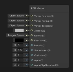
my node from the Lit Graph is different https://i.imgur.com/mixIFUS.png
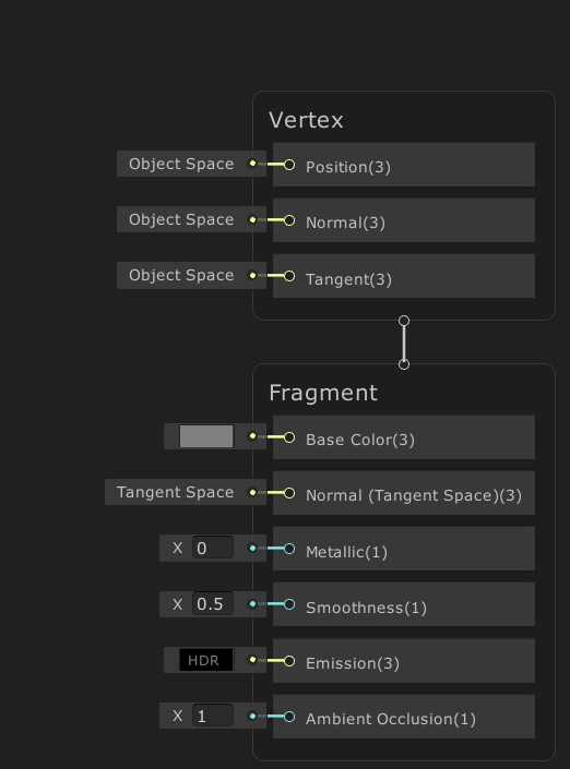
not sure if im in the correct channel, but why does it do this?
ive messed with the tiling but it did not help
How does one create a PBR Graph in Unity 2020.2?
Earlier in was like this https://i.imgur.com/GKlWNfI.png

@low lichen yes!
the idea is to execute a main command buffer in onPreRender, and then each camera that is currently drawing has a command buffer that draws procedural geometry based on the results of the main one.
Yes
Bad UVs on the mesh I guess ?
Maybe on the texture import settings, the texture might be set to clamp rather than repeat?
yea i think thats it too
it works fine on a cube
but it totally breaks on the houses
Hey guys,
I made a shader to create waves on my grass mesh to stylize it. I took inspiration from @regal stag works on his waterfall shader.
Actually it's UV dependent, aka ugly because I suck at unwrapping evenly.
I tried instead of UV to use the "Position => view" node and the waves where displaying perfectly ... but only in the view axis ofc.
Can I make this waves UV independant ?
@fiery crane try tri-planar mapping
Hi, How can i make a shader for UI so my world space UI sprites fade out when camera get close to them?
are all shaders made in the shader graph computed on the GPU? Especially vertex/mesh displacement etc? Is CPU doing anything at all?
@grand jolt I will start to read CatLikeCoding article about that then : https://catlikecoding.com/unity/tutorials/advanced-rendering/triplanar-mapping/
thank you for the advice !
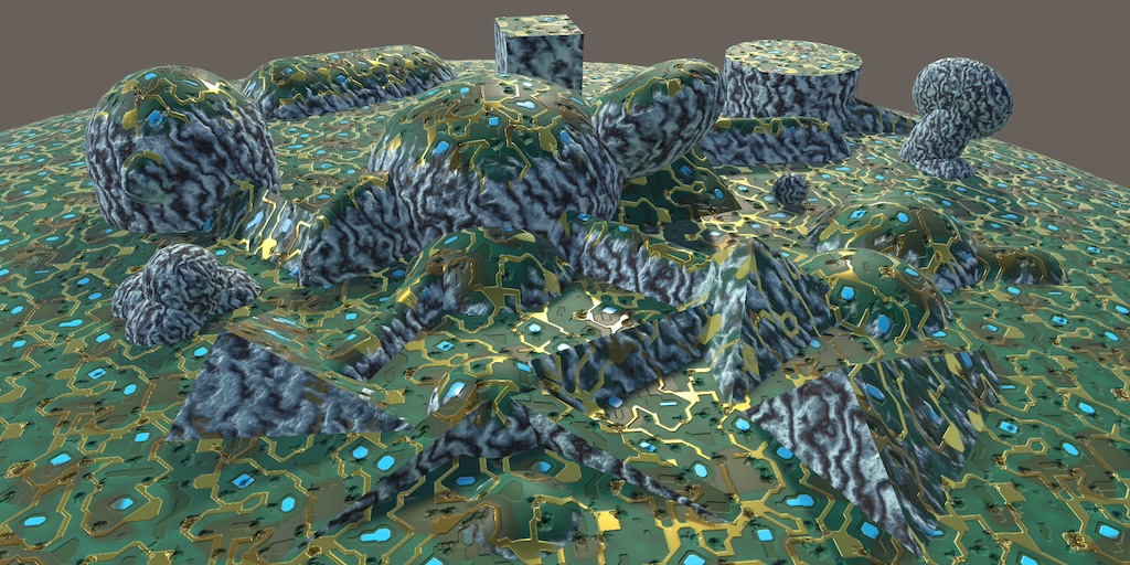
A Unity Advanced Rendering rendering tutorial about triplanar texture mapping.
if Amplify Shader Editor is so awesome and popular, why does it only have 260 Review? I mean I understand not everyone who buys it leaves a review, but still I would expect thousands of reviews, not 260. It's been around since at least 5 years, so it is very worrying.
How do you reverse noise with unity's subsurface shader?
Everything is on GPU
I don't understand
Was able to get it working! thanks again!
It looks like this.
https://i.gyazo.com/0d4efc7fbb0a8cb9c6d2c3a3c85fc1e3.png
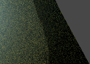
MMmmmmm I'm not sure how I can connect these two bad boys 😒
If I'm not wrong, TAA should take care of this eventually. But you seem to have a VERY wide radius for SSS, and this kind of out of the bound of what it should be.
triplanar can't take a vector4 in input ? i'm sad
Well, it sample a texture for each axis and blends them using the normal value.
But you could do the same for your effect : do it for the 3 axis planes, and blend with the normal.
Ok thanks. I'll try following this https://www.youtube.com/watch?v=UKIBGb5_JXk
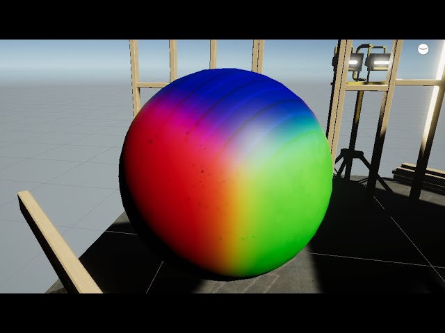
This is a Tut for triplanar mapping three textures or colors, which means one texture will cover the top and bottom another texture for left and right and the last for the front and back.
This way of mapping is common with terrains so that the faces facing upwards are grass and the sides are rock textured
Checkout my Low Poly Floating Islands p...
thank you 😄
I've created a fairly simple compute shader, that I've made 4000 copies of and run in parallel (as I need more than 4096 elements in my buffers).
It runs fast and I get a good response from the shader but it appears to be impacting the rendering as the 3d scene is jittery. Reducing the number of copies for 1000-2000 helps but still doesn't solve the issue.
The first time the shader is dispatched, the application freezes for a second or two, and then after that it seems to process the shader fine.
When I compiled the application and ran it, it was only jittery for the first 5-10 seconds and then things smoothed out.
I'm using Dispatch in FixedUpdate in a for loop for the 4000 shaders and using AsyncGPUReadback.Request to handle the response.
I've got RenderDoc but not sure how best to use it to diagnose my issues though I suspect the issue isn't the GPU but the CPU or transfer of buffers.
Question:
I have a shader with multiple emissive map options, which is used is dictated by a float input
Would it be more performant to do this, or have 1 emissive map, add it all to shader variants then have a bunch of duplicates of my materials with different maps applied.
Bearing in mind I have to use these materials in arrays and such. So it's 1 material with multiple maps VS several variant materials which would result in probably massive arrays.
although those arrays would only be used on game Start();
Damned, Art is hard. I already miss my shady code.
Welp, I must miss something but I don't get what:
There's two material from this shader in the scene. The green yellow, and the black yellow. (I try to make a cute wave transitions between these as you can see)
I am wanting to change the properties on my material for a specific instance of my prefab. However changing these properties changes the property on the prefab as well. Is there a way I can make these properties specific to an instance without writing code?
I am pretty sure you either duplicate the material for that instance or you have to change it in code. I don't think there's any other option.
How can you get a float3 variable consisting of the local (not global!) gameobject's X, Y, and Z positions?
an object is always at (0, 0, 0) in its local space...
Does anyone have a good guide to stencils and similar effects with shader graph?
I'm using 2d sprites, but the skinnedmeshrenderer doesn't work with the built in sprite mask. So an alternative that makes that work would be useful too 😄
@oak yacht Do you see these stutters as spikes in the Profiler?
Let me rephrase, the same values as you would on localPosition (relative to parent)
I'm not sure you can... I dont think parent information is accessible through shaders, i may be wrong though
@low lichen I'm not familiar with the Unity profiler (I've used others) I'll have a look.
I tried using RenderDoc but it's a bit too cryptic for me and I think the frames I was capturing likely didn't have my shader in them.
I saw some posts on the internet explaining about the JIT compiler in the GPU, so I've created a CSInit kernel that just blanks everything out / resets the shader data. Just trying it now, but I think it'll respond better.
I've also created a job queue so in each frame I'll only do a limited number of dispatches so as to not slow down the render pipeline too much.
A separate question, in the below code I'm getting a "The NativeArray can not be disposed because it was not allocated with a valid allocator". The NativeArray is from the UnityEngine.Rendering.AsyncGPUReadbackRequest though so I have no control over the allocator? I'm assuming I need to dispose this to release the unmanaged resource?
using (Unity.Collections.NativeArray<float> changeSetData = response.GetData<float>()) {
    UnityEngine.Debug.Log(changeSetData[indexOf(0,0,0,gridSize)]);
}
The request object doesn't appear to have a dispose/release method either.
ah, because I'm in a callback I guess it may release the resource after handling the callback.
My init and job queue approach seems to have worked, I'll just need a fancy loading screen or something until all the shaders are loaded.
reduced loading time and render pipeline is uneffected during load, but still a little bit of jitter when I first call shaders but it settles down quite quick.
Is the GPU JIT per kernel or per shader?
ah it's per kernel, I'll have to do a dummy run and then reset the data then I guess.
Any Ideas why it doesn't work as intended (both have the same material from this shader):
The top volume is Unity's basic cube
The bottom one is a mesh (without a bottom face)
Top variable is Green Color
Bottom is yellow and mix with Side (red) and Front (blue) according to a sine
So it works perfectly on the default cube, not on the weird mesh. 😢
@fiery crane But you're okay with the sides of the mesh blending between red and blue since they are diagonal?
It's just the yellow sine wave that isn't working?
The sine wave part isn't in your graph screenshot
That part is not working probably because the scales are different. I don't know if you're using the object position or the UV position for generating the sine wave part.
If it's UVs, make sure the UVs on the side of the mesh are what you expect.
@low lichen seems like it works only on perfect normals (the bottom weird mesh sides are not perfectly straight). I'll post the complete graph.
No UV. The idea is to be able to control the waves with Wave Length and Height and not be dependant on the Y position. and XZ be dependant on the object scale
it's sort of triplanar I think
I see you're using the object Y position for the sine wave. How certain are you that mesh goes from -0.5 and 0.5 Y like the default Unity cube does?
Because it might not be centered like the cube or use a different scale in its object space
I'm trying to do stylized grass blocks, with sides (XZ) blending with waves to the dirt around the grass block. the dirt is yellow here
MMMmmmm I don't use Y position for the sin wave, I use the Edge parameter to change the Y position of the wave
You're using the object position value to generate the waves. Could it be that the object is very small ?
Honestly, at one point it seems that setting proper UVs would be easier 😄
(I hate UVs and why do simple when I can do stupid hard ??? 😂 )
the 3 meshes here are very close to each other and scale 1 on the Y axis
another angle:
And on the XZ axes ? (that you use for the waves)
I mean this part. You're using the G/Y position as part of the wave
Either this, or for the mesh closest to the camera on this last screenshot you need to raise the edge value (sin wave is bellow the mesh)
changing the scale on XZ do exaclty what I want ^^ repeating the pattern
ok I'll try to dig around both of your last answers. changing the Y and affecting the sin wave height
thanks x)
OH DAMN
the pivot point of the weird mesh is not at center lmao
I'll try to change that first
UVs would be a nicer solution
You'd be able to support multi level meshes with that too, because two levels can share the same UV but they can't share the same position
Or slopes
UVs means moving vertices one by one 😢
Moving them?
yeah you're very right
placing the vertices in the UV panel in blender, to make them match the picture under it, no ?
you say that I draw the waves on a texture
and i apply the UVs by hand
for each vertices
damn, ASM is easier than art. 😂
Aren't there unwrap functions in Blender that could automate this?
yep there is, but i suck at drawing, that's why I want to use math and stuff all the time ^^
You need to draw to set UVs?
Seems like you think UVs require you to use textures. They don't.
I can move the vertices on the UV panel, but to be sure that the waves fit in the face i need a picture of it
Is there an easy way to implement depth sorting by triangle distance to camera? I have the case that I create a bunch of quads in runtime that get combined into one mesh and end up having really derpy sort order by creation order :/
This is in URP
Is this for a transparent mesh?
Assign your shader to a quad and take a screenshot 😄
Yes, I could live with switching to cutoff though
There is one other option, assuming it's okay if this mesh writes to the z buffer
You can draw the mesh twice, first invisible but writes to the z buffer. Then when you draw the mesh normal afterwards, all the faces behind the front faces will get Z culled because of the first pass.
hm interesting this could work because it doesn't break batching
It's not as efficient for the GPU as having the triangles sorted, but a lot cheaper for the CPU since it's just one more draw call and no expensive sorting required.
And sorting can't solve every case, if you have intersecting quads
okay thank you a lot, I think this points me in a good direction. I have a lot of gpu headroom even though it's VR because my shading models are very simple
yeah I would have this
it's for vr painting tool
so all the nasty edge cases you can imagine apply haha
Interesting. What does the painting have to do with generated quads?
The quads are used to paint with an alpha
still super early, started last week haha
Ah, yeah a lot of fun edge cases there :P
I'm not sure if the depth pass trick I mentioned will work here.
hm, because of intersection?
Are these quads combined into one mesh or all they all separate meshes?
every stroke get's combined once finished
Are you positioning the quads to ensure each new quad is slightly in front of the other, to avoid z-fighting?
this isn't really a problem because the controller tracking always adds a bit of noise to the position