#archived-shaders
1 messages · Page 105 of 1
Hi guys, i want to make a sprite sheet shader that can run animation of a sprite sheet texture, but i have no idea where to begin with.
I want to make it in shaderlab.
Maybe now that we've established the shader is completely fine but the render pipeline has shat the bed, I should move this question to #archived-urp , I'll go try that
Okay, actually, I've made a terrifying discovery because now it makes even less sense and it might be a shader issue after all:
If I intersect this with a plane, it works.
The shader absolutely shits the bed when it intersects specifically terrain. Which is, unfortunately, the thing I need it to do. The terrain is MicroSplat URP, and I am not touching that with a ten foot pole, that code is sacrosanct I'm not gonna cock it up. What can I do to this shader to make it work with MicroSplat terrain?
well now my wall is fucked

when I change layers from wall to default
i hate this sm dude
Does the shader output still look the same as the screenshot you posted after adding a Saturate node like Cyan suggested? Is it still a magenta version of the leaf pattern underneath it?
Because that suggests there are negative values involved with the alpha blending. And that is either coming from your output or what's already written there by the terrain shader.
No, the saturate node is making it a solid color, but it's still not detecting any sort of intersect, it's just a solid color.
Also it's blue now, I added the color to it when I was testing it against the plane to see if the finished shader works with that (it does)

Actually, this is without a Saturate node, but there is a Clamp before the color is multiplied that does the same thing

It's quite hard to follow your setup with only these screenshots.
But that's how it must happen :
- The exterior wall/ground etc ... are redered in the main view with the default layer
- a first renderer feature renders the stencil mask using a specific layer and the "stencil only" shader shows in the tutorial
- a second renderer feature renders the inside meshes, using an other layer, and with the stencil write to only display them where the mask was rendered.
it be easier if you just asked me what you need to know to help me out
I think you should try outputting the different values you are using to see which one is wrong. First I'd try connecting Scene Depth to Base Color, and then compare what you see when you place the object over a plane vs the terrain.
You may have to remap the depth to a 0-1 range if it's in a weird range.
It's possible that the terrain is not being included in the depth pre-pass, which would mean it would be absent in the scene depth texture. But that would be surprising, as that would break many effects that depend on scene depth.
Nothing noticeably different between the two

Did you set up the renderer features like I mentioned ?
i did what the video told me to
transperent layer mask is also the same as the opaque one


this is my main renderer
Nothing here looks like a setting for that, does anything jump out at you that might be wrong? I'll also poke around the other MicroSplat SOs and see if anything looks depth related

its on the correct layer

I'm looking for a depth gradient, but it's all white, so the range is probably very large, making it harder to see a difference. Could you try multiplying it by a very small number until it starts to become gray?
Okay, multiplying by 0.1 gets different results. Plane is showing through the object, terrain is not.

Alpha is 1 in both cases
And you also have the stencil mask object with it's shader ?
Ok, good news it that confirms the problem is that the terrain is not in the depth texture.
Bad news, if the terrain asset has no option for including it in the depth pass, there's nothing you can do to fix it, without modifying it yourself.
Welp
But it's extremely unlikely that this is an unknown issue. Maybe you need to update the asset, or the asset hasn't been updated yet to work properly for the URP version you're on. Or maybe there's a setting somewhere.
glass works just fine, but in the video he is using the same shader he wrote for both the ground and the hole


Okay, I'll try to update MicroSplat. It's a fundamental necessity to have these splat maps so I haven't wanted to rock the boat but I guess that's what version control is for
and I did the same but the walls just disappear, im trying to restart my walls and just start again to see what i did wrong
see it wont render back with the shader on the material

Not, the ground has a default material and the hole has the stencil mask material.
so in my case the hole is the window

Yes
nada
And the big wall here is in the "wall" layer used but the renderer feature ?
And the window is in the default layer ?
yes, the wall has the wall layer

and the window is in the default layer, yes
Cause the window here is in the wall layer ...
what im selecting is the wall object
on that screenshot
because it was invisible
wait you're telling me I setup this up the other way around? 😭
If what you've said just earlier is correct, you should be good.
The window that acts like the stencil mask must be in the default layer.
And the wall that is forced to be rendered after must be in the wall layer.
i dont get it, then what is wrong 😭
i get what you say, but like, how tf could it be wrong if I followed the video 100%
Now, one thing to be also sure of : you've added the renderer feature to the "Ultra_PipelineAsset_Forward" : is this the current active one ?
If you have multiple quality levels in the project, each with a different render pipeline asset assigned, it might not be the case.
it is the current one, yes
i dont use multiple qualities I just use a main one
which by default is ultra i believe
Hum, well, if the wall disapeared when you removed the "wall" layer from the opaque mask, it should indeed be the current active one.
I'm out of ideas, should work from the informations I have 🤷♂️
question, my wall needs the shader aswell right? when i had it on the wall, it became invisible
nope it did the other way around
well i removed it from my wall layer it just became like this (with the shader thats on my glass object aswell)

the shader on the wall material that is
Can you show the code of the stencil mask shader ?

just like in the tutorial
then I applied it to my glass material and it worked, then onto my wall material and yeah
Why do you want to apply it to the wall ? The wall must use a regular shader.
because on the video he applied it onto the ground aswell
No
well its fixed now (normal shader in the wall), but i still persist with this issue
So, you have this rendering, the front face of the smaller "cube" is the glass window, it has the stencil mask shader, but it is not seethrough ?
yup
wait hold on, it might be something entirely different let me confirm
nope, its not something entirely different

well shit
ok im stupid 😭

it was infact something else
May I know what was the issue ?
ok so the way i spawn my shopfront is through cloning a prefab, and the said prefab was 1 cube that i eventually seperated the front face (glass part) and the shop's inside (red and blue part) and put them both under a parent for easier movement in the scene, then my script did clone the parent like it was supposed to, but it set it to another random place with wrong sizes and when did put it on the right place in the editor, it wasnt working, because guess what, the glass material was not being dragged along

so now its only moving the glass part and i'm just going to add the shop behind (like I originally wanted because it'd be weird for a shop to be 50 centimeters tall and follow the window)
If it helps, you don't have to have mutliple objects to have a mesh with multiple materials.
i know, thats what i had going
(or just move the proper parent object 😅 )
each face was a different material
but the same object essencially
not sure if my my explanation makes sense but yeah, im making a shopfront simulator as a pitch to my company that im interning, its in my interest to actually get hired and work here haha
Ok somehow the flipbook shader is making the particle animations less smooth. It jitters/flickers around. Why could that be happening?
is there any setting on the particle system that could be not jiving with it?
im trying to make a stereogram shader, and make it like duplicate to the sides to create the false focus effect but it doesnt seem to be working. can someone help?

I've never been able to see autostereograms myself, so I can not verify if it works 😅
But from what I understand, the principle is to shift left or right the pattern based on the depth map, right ?
Isn't it what is happening ? Can you also share the shader code/graph ?
There's definitely an auto stereogram there though not working properly (looks like it's partially duplicated horizontally, the axis symbol in the middle doesn't help seeing it though). Without seeing the shader it's impossible to tell what's going on. Have you checked papers like these: https://projet.liris.cnrs.fr/imagine/pub/proceedings/ICPR-2016/media/files/1621.pdf. That seems to pretty much provide the exact formula required to produce such effect
Now that I look at it, that link isn't maybe exactly what you are looking for but I'm sure there's ton more resources and even shaders available online (there seems to be multiple on shadertoy for example)
is there anyway to make the shader have a glassy look?
while yes its does its job, but i wanna know if it can also look a bit like glass instead of only a cutout
Look up some refraction shaders
well you are correct, but thats not quite what its doing atm. still working on it.


never heard of shadertoy before, but yea these do seem like they work. they work like how i expect them to and are solvable.
It's a great place to find shader ideas. Shadertoy uses GLSL but the languages are pretty similar. vec3 -> float3, mix -> lerp and so on.
sick,
While searching for something totally different I've just discovered that a former colleague did some stereograph shaders and open sourced the project : https://github.com/cinight/ShadersForFun
yooooo nice find bro! https://streamable.com/7tsfn0

omg this is a goldmine

Does anyone know the proper way to read triangles out of sprite geometry? I want to convert a sprite with custom uvs and geometry to a texture I can save to disk. I'm not overly concerned with how long it takes and I don't want to wait for and have to deal with callbacks for draw frames so I wrote this as a gpu shader-ish thing. Problem is taking the triangle indexes in groups of 3 like this just leaves me with a bunch of bottom rights and there appears to be repeats. In-Game the sprite renders like I would expect.
So A) Do you know what's wrong with this snippet?
Or B) Do you have a better way to instantly render a sprite to a texture2D, like Graphics.Blit but for sprites? As if they were in an Ui Image component

_texture = new Texture2D((int)sprite.rect.width, (int)sprite.rect.height);

for (int i = 0; i < sprite.triangles.Length; i += 3)
{
    var a = sprite.triangles[i];
    var b = sprite.triangles[i + 1];
    var c = sprite.triangles[i + 2];

    var vertA = sprite.vertices[a] * sprite.pixelsPerUnit;
    var vertB = sprite.vertices[b] * sprite.pixelsPerUnit;
    var vertC = sprite.vertices[c] * sprite.pixelsPerUnit;

    var uvA = sprite.uv[a] * sprite.rect.size;
    var uvB = sprite.uv[b] * sprite.rect.size;
    var uvC = sprite.uv[c] * sprite.rect.size;

    var minX = Mathf.FloorToInt(Mathf.Min(vertA.x, vertB.x, vertC.x));
    var maxX = Mathf.CeilToInt(Mathf.Max(vertA.x, vertB.x, vertC.x));
    var minY = Mathf.FloorToInt(Mathf.Min(vertA.y, vertB.y, vertC.y));
    var maxY = Mathf.CeilToInt(Mathf.Max(vertA.y, vertB.y, vertC.y));

    for (int x = minX; x <= maxX; x++)
    {
        for (int y = minY; y <= maxY; y++)
        {
            //I want weights based on vertices, and final values based on uvs
            var denom = ((vertB.y - vertC.y) * (vertA.x - vertC.x)) + ((vertC.x - vertB.x) * (vertA.x - vertC.x));

            var weightA = (((vertB.y - vertC.y) * (x - vertC.x)) + ((vertC.x - vertB.x) * (y - vertC.y))) / denom;

            if (weightA < 0) { continue; }

            var weightB = (((vertC.y - vertA.y) * (x - vertC.x)) + ((vertA.x - vertC.x) * (y - vertC.y))) / denom;

            if (weightB < 0) { continue; }

            var weightC = 1 - weightA - weightB;

            if (weightC < 0) { continue; }

            var finalUv = (uvA * weightA) + (uvB * weightB) + (uvC * weightC);
            _texture.SetPixel(x, y, sprite.texture.GetPixel((int)finalUv.x, (int)finalUv.y));
        }
    }
}

_texture.Apply()
Hey so I've got a question concerning the Stencil Buffer. I want to be able to have a scene viewable from inside a card. I understand the logic behind the stencil buffer and comparing against some assigned ref value. My question is, when multiple cards ovelap, how do you prevent the "inner worlds" from overlapping as well?
Unity Sprite Masks seem to have the ability to be nested, and I know they use the stencil buffer behind the scenes. How do they work under the hood?
why is this happening with my triplanar shader material?

nvm i smoothed out some edges in blender and its fixed
I'm trying to make a flow stream on a spline based mesh. But when I use tiling and offset to move the UV of the noise, it Becomes gibbrish and moves (to me) randomly
I send the shader and subshader as well
Does anyone know what goes wrong?


This is the world normal Y dir, which looks fine to me

You need a constant offset along the mesh or certain parts will offset more than others causing the texture to stretch and lead to the very noisy result when Time gets larger.
I'd hope the spline has appropriate UVs (which it kinda looks like it does), so to scroll along the spline you should be able to use a panning Speed of (1, 0) or (0, 1)
If the aim is to get some parts panning faster than others, then you can do multiple samples at different speeds and blend between them based on the normal
Ah got it. I thought that just changing the speed would work, but guess not haha
I'll try blending 2 speeds after lunch, thanks!
after upgrading to 6.1 the shader i use throws this error
[Worker4] Shader error in 'Universal Render Pipeline/Custom/Lit Tessellation': unrecognized identifier 'FragmentOutput' at Displacement/Shaders/LitTessellationPasses.hlsl(188) (on d3d11)

Compiling Subshader: 0, Pass: GBuffer, Vertex program with <no keywords>
Platform defines: SHADER_API_DESKTOP UNITY_ENABLE_DETAIL_NORMALMAP UNITY_ENABLE_REFLECTION_BUFFERS UNITY_LIGHTMAP_FULL_HDR UNITY_LIGHT_PROBE_PROXY_VOLUME UNITY_PBS_USE_BRDF1 UNITY_PLATFORM_SUPPORTS_DEPTH_FETCH UNITY_SPECCUBE_BLENDING UNITY_SPECCUBE_BOX_PROJECTION UNITY_USE_DITHER_MASK_FOR_ALPHABLENDED_SHADOWS
Disabled keywords: DIRLIGHTMAP_COMBINED DOTS_INSTANCING_ON DYNAMICLIGHTMAP_ON INSTANCING_ON LIGHTMAP_ON LIGHTMAP_SHADOW_MIXING SHADER_API_GLES30 SHADOWS_SHADOWMASK UNITY_ASTC_NORMALMAP_ENCODING UNITY_COLORSPACE_GAMMA UNITY_FRAMEBUFFER_FETCH_AVAILABLE UNITY_HARDWARE_TIER1 UNITY_HARDWARE_TIER2 UNITY_HARDWARE_TIER3 UNITY_LIGHTMAP_DLDR_ENCODING UNITY_LIGHTMAP_RGBM_ENCODING UNITY_METAL_SHADOWS_USE_POINT_FILTERING UNITY_NO_DXT5nm UNITY_NO_SCREENSPACE_SHADOWS UNITY_PBS_USE_BRDF2 UNITY_PBS_USE_BRDF3 UNITY_PRETRANSFORM_TO_DISPLAY_ORIENTATION UNITY_UNIFIED_SHADER_PRECISION_MODEL UNITY_VIRTUAL_TEXTURING _DETAIL_MULX2 _DETAIL_SCALED _GEOMETRY_CUSTOM_ST _GEOMETRY_CUSTOM_UV_CHANNEL _GEOMETRY_UV_CHANNEL_0 _GEOMETRY_UV_CHANNEL_1 _GEOMETRY_UV_CHANNEL_2 _GEOMETRY_UV_CHANNEL_3 _HEIGHTMAP _HEIGHTMAP_BLUR_BOX _HEIGHTMAP_BLUR_GAUSS _MAIN_LIGHT_SHADOWS _MAIN_LIGHT_SHADOWS_CASCADE _MAIN_LIGHT_SHADOWS_SCREEN _NORMALMAP _PARALLAXMAP _RECEIVE_SHADOWS_OFF _TESSELLATIONMAP _TESSELLATION_CLIPPING _TESSELLATION_DISTANCE _TESSELLATION_EDGE _TESSELLATION_PHONG _VERTEX_COLOR _VERTEX_COLOR_ADDITIVE _VERTEX_COLOR_DISPLACEMENT _VERTEX_COLOR_MULTIPLY _VERTEX_COLOR_REPLACE _VERTEX_COLOR_SUBTRACTIVE
any idea how to fix it?
why cant i connect this to vertex position

Sample Texture 2D cannot be used in the vertex stage. Use Sample Texture 2D LOD instead
I'm trying to recreate the effect in the first shader, where (I think) this scrolling effect is based on a normal's angle relative to the camera's position. The second shader is what I've been able to come up with. How do I get that effect?
https://cdn.discordapp.com/attachments/437747715682730004/1376003503239073863/2025-05-24_21-06-06.mp4?ex=6833bea0&is=68326d20&hm=3c2425adef8020d12d5ce4706b2ed3c3613024db1417b149b9f88a0d8e9a0863&
Hi, I'm doing lighting/ao with a raymarching SDF system, and I'm getting this kind of weird artifact. Could anyone give me any hints on what could be causing it, what this kind of artifact would be called.... any clues really?

it seems to mostly happen when my light is near a flat surface like a wall or ceiling then this pattern emerges on the opposite side, ie if light near ceiling it happens on the floor
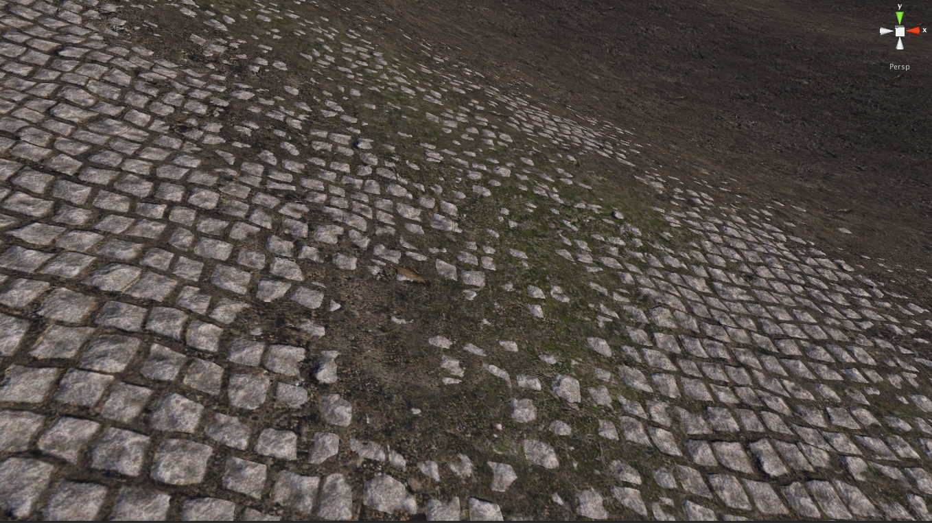
please suggest a way to make my terrain less pathetic? can you see something wrong/bad

I'm intersted in shader stuff. Not terrain placements.
The room for improvement I see is not really related to shaders
Mostly it's lacking in geometry detail like foliage, rocks and most importantly ridges
Height map terrain cannot really represent rough or vertical surfaces
it is, lots of it is shader. for instance, i do not have something like this (see at 14:05)
https://youtu.be/mP8eHwVEA0o?t=845
Do you know how that works ? normal blending ? maybe you can help me here?
Are you using Terrain shader or a custom shader to begin with?
custom
dw, i'm a bit advanced, you can talk at any complexity you want i probably can understand you.
Then it won't be a lot of trouble to implement custom blends as well
Unity's terrain shader can use heightmaps for blending, which aren't necessarily heightmaps but any data used as alpha bias to the blend operation, meaning some parts of the texture, like cracks between tiles blend more
This type of normal blending looks to be similar, instead I think it translates normal map to world space and determines the blend bias based on verticality
So in that example the grass favors flat surfaces and avoids inclined, or vice versa for rock
lol dude, i told you im a bit advanced
i already do that
i use splatmaps, color mask maps, triplanar blending
etc
but there, normal blending is not using slope
if you cannot tell, its a detail thing. no texture can reach that accuracy without beign at least 100kx100k.
i think he uses normal maps or sth im not sure
The two techniques I described aren't exactly any of those three
wym ? a splatmap is a map with 4 channels of heightmap
"translates normal map to world space and determines the blend bias based on verticality" can you describe this?
more
Technique 1 is "height blending" which uses an additional texture for each terrain layer to get a blend bias
Technique 2, this type of normal blending would read the world space result of applying the tangent space normal map onto your terrain geometry and get its verticality using dot product, and use that as bias when blending
ah technique 1 you mean a mask map for detail
yeah, he doesn't use that in there
Detail masking is something else, to be exact
wym? detail mask is adding a mask over the detail albedo, to taint it with another texture
our detail is the layer texturee here
yes great idea, i think he uses tangent space norm
Detail mapping is to add another finer texture layer on top of your first one for either albedo or normal typically
Detail masking is to exlude some parts of the texture from detail mapping, for example if your texture has more than one physical material
This rather is introducing a map as bias to the blending of two terrain layers
On the specific terrain layer
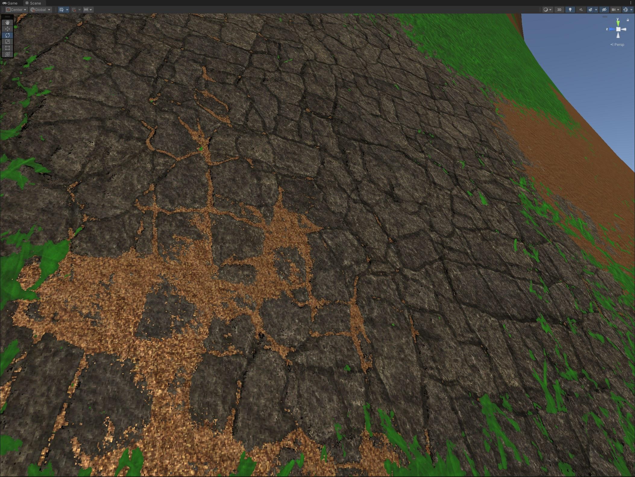
This shows that the cracks between the stone layer have a lower height (or "bias") so the green and brown textures blend more there
Normal blending would be the same technique, but not using a separate height map
Rather figuring out the verticality using a normal map
you mean something like a depth map with wich you multiply the splatmap channel of the said detail ?
Yes basically
you mean sth like this?

That resembles a height map that can be used for height blending, yes
Still, the normal blending in the video does not utilize an additional map like that
But the concept of introducing bias into the blend operation is the same
well, that's what i called detail mask map before tbh, but i do not think it will be able to do something like this, as using such a map will taint the entire "rocks" with that golden color you had here
here it seems more like a : MaskRocks = splat.r x bigMask.r x detail_mask.r
The bias can go the other way just the same, so the rocks creep into the grass
If you want to use normal blending, the appearance will be roughly similar but vary based on incline
The second image to my eye has no detail mapping at all, while the first one might be
Detail mapping is a totally separate effect though
We're talking about the blending of two terrain layers
A layer includes all PBR maps of a material, including detail maps and detail masks
Anyway, that's just two techniques to improve the terrain with shaders
yes, it was just an example.
honestly, that looks like an expensive step that will barely add realism in my terrain (in this exact terrain ecotype) (maybe in a snow environment)
Additionally what comes to mind is to potentially have some subsurface scattering / softer lighting for the grass/moss, and possibly tessellation for the rocks
yeah i thought about tesselation, i think imma try it and see if there's any improvement. but honestly will still be too far from the compared image.
subsurface useless there (and too expensive)
Though those options are usually considered after you've already been sprucing up the place with detail geometry
No matter how good your shaders are it'll stand out how simple and blocky the ground is
In fact if your shaders are not very photorealistic people will forgive the blocky and barren terrain more easily as well
But there's few reasons not to have some shrubs and rocks at least
just take a look here
this is a terrain.

no other geometry added.
it already looks photorealistic without need of rocks or vegetation.
im trying to level up my shading game
not interested in placements
There's a lot more geometry detail there, and probably tessellation, or the ridge itself could be a separate mesh
Meshes can be blended so it won't be easy to tell where one begins and terrain ends
You’re not achieving that with Unity terrain. Need virtual texturing for that kind of detail
virtual texturing of what ? the heightmap of terrain ?
Mostly the splatmap but yeah that too
Right now having that kind of density just uses way too much memory since it’s all loaded at the same time
I think you can do this all with repeating textures and duplicate assets no problem
The example would look very barren without any meshes
yeah i think its doable too
maybe yeah, they are using another blended mesh into terrain
Here's just a few ridges that I believe are generic meshes on top of the terrain

The rocks and plants all over that look like meshes obviously aren't terrain either

Meshes can be blended seamlessly
Oh I didn’t get the full screenshot
Yeah you can see a clear difference in shading, even
yeah ik, it just looked doable using just a heighmap
here's the original time of the screenshot btw https://youtu.be/6NQUbFiUYRw?t=981
Doesn't look like they're using much or any of that fancy mesh blending either
Probably height/normal blending, or the ridge textures have been baked with the same techniques
I think good looking terrain is like 80% credit of detail objects that cover up all the imperfections
The river pebbles and short grass for example effectively covers any terrain layer blending (or blending issues) there might be
Sometimes even texture repetition isn't necessary to avoid because a fully furnished environment won't have big plains where it'd become apparent
Even this game that's all about big plains is remarkably stuffed with detail
yeah repetition is almost never necessary to avoid. a color mask maybe is enough, the vegetation / rocks will do the job
anyway, do you suggest anything i can do to increase realism without meshes or crazy expensive stuff?
With terrains it seems usually doing "more" makes it easier, contrary to how typically making something simple keeps the task simple as well
Better PBR maps is one possible option
But why avoid meshes?
doing "more" makes it easier?
cause my point is to get good at shaders, not the outcome itself
Could construct the whole thing with mesh shaders I guess
More detail hides the flaws and forms a coherent, familiar sight
Visual context is very important for the illusion of realism
It's a bit hard to know if you're succeeding at getting better if the result is blocky and uncanny no matter what you do
But you do have the blending techniques to practice, and if it's for practice there might not be a reason to avoid the crazy expensive techniques either
Mesh details are good for practicing shaders too, when you've got foliage translucency, wind effects and blending rocks and cliffs with the terrain splatmaps
i agree with you that they do help in achieving realism. but i believe we probably can get something super realistic without any

here i baked the splatmap at higher resolution, and changed slope a bit, and added whole terrain normal map, it looks just a bit better. i will try to add tesselation
anyway thanks for the helps! @grizzled bolt
Does anyone have any idea on how to replicate this effect using shaders? When the user clicks on the image, a 1×1 area rotates revealing an image behind it, like this image

i need to keep it in world space in order for the lighting to work correctly but the texture gets ruined how do i fix it

I need help recreating this shader in Unity...
Image one shader setup - blender
Image 2 custom Shader - blender


this is what it looks like
Im completely new to Unity... so i have no idea where to start, unsure if its even possible
anyone got better idea please?

That pretty much covers it...
I’m sure it’s possible but I’m not sure what the intent here is. It just looks glitchy, for the most part.
We multiply the… light path? Of the 1x (first?) camera ray by a texture? What does that even mean?
unsure, i followed a tutorial
prob not the best way to go about it
It just makes no sense 😅
i can send a link to the tutorial if youd like
That might be helpful
should i dm you or send it here
https://youtu.be/1jWNeLujtV8?si=JiLbRUckMmIg91Mf (lmk if youd rather dm)
Today I will show you how to make any render looks like a painting!
👇Parts👇
00:00 - Introduction
00:57 - Part 1 : Geometry | Aligning Instances to the Camera
02:36 - Storing Attributes and Final Touches
04:25 - Part 2 : The Shader Magic | Brush Texture
05:19 - Setting up the Transparency
05:54 - Fixing the...
I'm trying to solve 3k0o_x's question but so far my attempt always has these weird curves.
This is probably due to adding/substracting UVs on each other, are they not perfectly linear perhaps? Graph is a stringy mess


This is the end result, i guess the curve isnt so noticable. You do need the tile as a separate texture tho, because it needs to go into texture sample which doesnt accept edited stuff.


Can you not define an Array of floats in shader graph?
Or colors?
Or any arrays other than Textures?
i dont see how thats relevant, tbh, but im not an expert
Hi all, what URP shader should I be using for leaves on trees? I am currently using speedtree8 because its the only one i could get to work how i wanted but its giving me a strange white gradient/fog effect on the leaves

could be easier if handled by c# script instead of shader, might save you from unnecessary headaches.
You can apply a 3D rotation to the position and normal before the triplanar nodes.
Note that if you have an other object somewhere that is not oriented like the one in the screenshot, it might be that other one who ends up with a bad orientation ...
Maybe the best here would be to use proper UV mapping instead of a heavy triplanar projection ?
More "Rotate About Axis", which is for 3D vectors.
Well, in your case it seems to be as simple as taking the Rotate About Axis node, input the position, use (0,1,0) as rotation axis, and find the perfect rotation angle (use an exposed float) to match your 3D asset.
Then use the same for the normal.
But because what I see in the screenshot is a float road mesh : why not simply edit the UVs to texture it properly ?
a road can just be a normal material with tiling set correctly...
or using world pos to sample a texture uv in a simpler way
I made a Full Screen Radial Blur Shader and assigned it as a Renderer Feature. but the problem is that the shader also affects my scene view :/ is there a way to make this Renderer Feature only affect the Game View?
You can add code in the renderer feature to check for the current rendering camera.
I don't remember the exact name (you can check by logging), but you can skip the feature if the camera names matches something like "SceneCamera"
alright, thanks
so i dont really know how to properly ask this question but here goes.
i'm trying to erase, or transparent some colors from one node so i can add it ontop of a different node together to get a combined node together.
like in this picture for this case, i want to take the black part from this floor and make it gone when i place it onto another node, so only the white part is getting written on it

Lerp or mix node can be used to combine 2 colours inputs, using this as the "mask"
ah ok, i think that helped. thanks ^^
Are shader graphs and shader scripts just two versions of making the same thing? Do they compile to the same script?
this death stranding?
Yes. Graphs even generate shader code behind the scenes, you can view it by using the "View Generated Code" button at the top of the inspector when the graph asset is selected.
thanks
i want to random between 2 colors so i have variations for my grass, how can i do that?
urp shader graph
Hello. I'm currently writing a full screen post processing shader. I'm trying to sample the color of each pixel during a pass that way I can transform it. How do I do this?
can someone help me fix this bug with the materials? it looks like the material is drawing on top of itself,enabled alpha clipping and transparent surface type,ive tried everything and it keeps doing this weird effect
the models worked fine when i used them on godot so maybe unity has a different way for rendering alpha clips?
hello! I'm trying to create a grid system in unity, that shows itself to the player. Ive seen a couple of tutorials for applying a shader to a plane, but how do you apply a grid to a unity terrain? Does anyone have resources for learning how to accomplish this? for clarification the project is URP and im just using unitys default terrain
nvm i fixed it,apparently the engine has way more options than i originally thought,i just had to use the cutout rendering pipeline instead of the default URP
I don't think there's such a thing as "cutout rendering pipeline"
I made a grid shader a while ago. I forget if shader graph works with terrain or if you would need to implement splat map stuff yourself:
https://preview.redd.it/any-suggestions-to-make-a-glowing-grid-on-the-ground-aside-v0-8k65ddtwc5he1.png?width=1919&format=png&auto=webp&s=2443f8ea3d2701347139c6299602f3e76fa5be30

a simpler version can be done without smooth edges
the unity samples does have a procedural grid that i was testing out. it works well, albiet a bit simplistic on the ground, but it was using a decal shader, and doesnt work well on slopes.
you can use similar techniques like I did above to use world position to produce grid lines
slopes will still have this problem however because thats just how it works
yeah, right now i was thinking of just clamping my decal projector transform's position to a place on the grid to keep the grid lines the same, but being able to use world position to produce grid lines seem better.
you can get a decent result already using step with world pos
I am extremely new to unity, as in I just downloaded it. I understand that I need a render pipeline but for some reason the default is none. I was able to change one manually in the inspector but I'd like to do it for everything. How could I set the default render pipeline?

I deleted the one I had and re-extracted a new Unity Essentials . zip and now it works lol
You don't "need" a render pipeline, when none is assigned Unity renders with the "Built-In" render pipeline, which is a slightliest older technology, but still works.
But using one would be highly recommended
I recommend URP if you don't know what RP you need
None/BiRP if you know you need to use legacy assets or tech
HDRP if you know you know what you're getting into with it
Sorry for the inconvenience.
I need to create a function that takes all the incoming lights and gives them to me as output to then apply nodes to them later.
Every time I create a hlsl file where I put the functions (made by AI) it always gives me errors on this function:
undeclared identifier 'GetAdditionalLightsCount' at Assets/prova/prova.hlsl(4) (on d3d11)
Can anyone tell me what I should do? I'm going crazy.
i'm using Unity 6

Did you #include "Packages/com.unity.render-pipelines.universal/ShaderLibrary/Lighting.hlsl" like mentioned in the docs ?

if i include that, the project give me another error
Its actually #include "Packages/com.unity.render-pipelines.universal/ShaderLibrary/RealtimeLights.hlsl"
Lighting.hlsl does use the function it seems (i was looking in the src just now)
same
i'm going crazy
What error
Im on 2022 so there is a chance it moved in later unity versions

Custom functions for shadergraph can't have return types, they need to be void and use out params instead.
Include files specific to render pipelines need to be surrounded in #ifndef SHADERGRAPH_PREVIEW blocks (including them in previews will cause conflicts due to how shadergraph handles those). In this case Lighting/RealtimeLights is already included anyway.
I have custom lighting nodes here you can use as an example/template : https://github.com/Cyanilux/URP_ShaderGraphCustomLighting
(specifically AdditionalLights_float in the CustomLighting.hlsl file)
hhmm ok.
can u write me in private chat? i want to ask u something
No
ok sorry
If you want to ask help about shaders, here's the channel for it, so answers and solution are publicly visible and can be shared.
Hey dudes, how can I reference a shader existing in the package cache path in my shader code?
You can reference include files from packages, but not .shader files.
#include "Packages/com.unity.render-pipelines.universal/ShaderLibrary/Core.hlsl"
its been a while since i did some shaders, whats the node(s?) to tile a shape ?
for instance im trying to make a rectangle repeat indefintly, so i know i need the Tiling And Offset node at some point, but using it as a modifier for the input or output doesnt seem to give the desired result
nvm i found it back
Tilinge & Offset -> Fraction -> Shape
im working with the unity toon shader rn, I want to try and programatically access the rim light toggle but im not sure how to. Using float = 0 / 1 for on and off don't work, how can i deal with this?

Is there anyone who speaks Arabic here?
Check that the toggle isn't also linked to a shader keyword that you have to enable/disable using Material.EnableKeyword
what should i do to make my canvas shader not scale withthe imahe container ?
i can't find any shader keywords in the shader
i assumed the underscore meant like
not tied to a keyword
Hum, yes, indeed, it forces it to no binding...
So setting it to 1 should be enough 🤷♂️
I see in the source code that there's a lot of other rim light value that you might need to change ?
im setting the values to 1 and 0, but its not changing anything 😭
the other values i've pre set
Do you see it actually change in the inspector ?
in the inspector, no, but when I use "GetFloat" in the console the values change accordingly. but when I change it in the inspector the console doesnt reflect these changes
Can you show a bit of the code ? Looks like material duplication.
Yeah, so basically in the start function I cache the list of materials in the materials list, like this
characterMaterials = characterRenderer.materials;
and then in the update function i do this
if (characterEntity.intangFrames > 0 || characterEntity.invulnFrames > 0)
        {
            foreach (var mat in characterMaterials)
            {
                mat.SetFloat(RimLight, 1.0f);
            }
        }
        else
        {
            foreach (var mat in characterMaterials)
            {
                mat.SetFloat(RimLight, 0.0f);
            }
        }
You need to set back the list after modifying the materials.
characterRenderer.materials = characterMaterials
ohhh
https://docs.unity3d.com/6000.1/Documentation/ScriptReference/Renderer-materials.html :
Note that like all arrays returned by Unity, this returns a copy of materials array. If you want to change some materials in it, get the value, change an entry and set materials back.
hello, anyone got experience with compute shader? i'm having a problem because my compute shader code keeps making my Unity crash, i already described my problem on Unity Disscussion: https://discussions.unity.com/t/my-computeshader-keeps-crashing-failed-to-present-d3d11-swapchain/1648319
so, im both new to the server and unity, I wanted a bit of help on this issue ive fallen into, i was following this guide about making a graph and it had a segment where it was making a standard surface shader, im using the built in pipeline, and my code looks like this.
Shader "Graph/Point Surface"
{
    Properties
    {
        _Smoothness ("Smoothness", Range(0,1)) = 0.5
    }

    SubShader
    {

        CGPROGRAM
        #pragma surface ConfigureSurface Standard fullforwardshadows
        #pragma target 3.0

        struct Input
        {
            float3 worldPos;
        };

        float _Smoothness;

        void ConfigureSurface(Input input, inout SurfaceOutputStandard surface)
        {
            surface.Albedo = input.worldPos;
            surface.Smoothness = _Smoothness;
        }

        ENDCG
    }

    Fallback "Diffuse"
}
but when i apply the shader to a material, its just pink, and i am really confused on what could be the problem
i downloaded unity recently, so my editor is v 6000.1.4f1
the shader was going to change the colour based on world position, but I cant figure out how to make it actually render colour instead of just error and render pink
Hey! Im currently working on trying to figure out how to make a shader, but i am very new to unity, ive watched tutorials and followed them but i cant figure out how to make what i want… would anyone be able to help out? maybe in dms?
tried using shader graph? You have to think differently with shaders, the shader is executed per pixel to calculate the resulting colour (often then lit by unity)
you can do something easy like use time to offset the uv used to sample a texture and it will make it animate!
https://learn.unity.com/pathway/creative-core/unit/shaders-and-materials/tutorial/66fc4313edbc2a0023a2538a (an intro course for shader graph)
Unity Learn
Free tutorials, courses, and guided pathways for mastering real-time 3D development skills to make video games, VR, AR, and more.
I have tried, ngl im quite confused, i think what im trying to make might just be really complicated... but im unsure- i made it in blender but idk how to replicate it in unity
ill look into this thank you
blender kinda works the same way but you cant do everything there also in unity. Blender lets us do some cheaty things as it doesn't need to be realtime
ohhh
are you able to dm? maybe call...? that way i can show u my problem (if not no worries!!)
Its better to share here so many people can help out at any time
ohh good point
ok so im trying to make a shader that looks like this

(the pink is the light, base color is blue, i used a toon shader on top of some geometry nodes)
this is without the shader, the issue is im 95% sure that all those faces would be alot for unity real time rendering (the faces always face the camera)

I can send the tutorial i used for making this if thatd help?
you can draw lots of geometry cheaper with gpu instancing. lots of overdraw can be an issue however
unity also has functionality to draw geometry direct from code cheaper without gameobjects
Worth the effort, finally done
Share !code here next time. We don't need to jump between several links just to see it.
Your compute shader has a lot of loops, so you're likely getting an infinite or close to it loop. I don't see where you assign or expose the loop length variables, so perhaps they're uninitialized.

Posting code
📃 Large Code Blocks
Use links to services like:
https://paste.mod.gg/, https://hastebin.skyra.pw/, https://paste.ofcode.org/, https://paste.myst.rs/
📃 Inline Code
Surround code with three backquotes. Not quotation marks.
To format as C#, add cs to the first line:
```cs
// Your code here
```
Add a comment with a line number if there is an error message.
i was told the yellow slash could be a shader

i would like to recreate something similar
if it isnt a shader please direct me to the right channel
While there are shaders involved at some level, I think this is mainly particles with custom meshes.
Maybe look at some tutorials on vfx and particle systems for similar affects.
Could also be line renderers too.
i believe particles because as i watch i dont think its a fixed thing because it follows him wherever he is
unless its part of his animation and im dumb
Meshes and line renderers can be modified at runtime. And shaders can be used to different meshes differently over time. It depends basically
left: shader graph output
right: stretched in the image component


I have a question
Please help me out from my problem
I want to use shaders in my URP game but the shaders that I want to use are made for Built-in so
How I can upgrade them to URP.
It's never shader alone, either mesh or particle or trail, well, particle and trail are basically also mesh
I created a shader with 8 textures and one shader with 2 textures atlases. Which one with perform better? I'm not sure since the node tree with the atlas textures looks hella scary


It's hard to say. You should test and profile.
My guess is atlas would be better due to possibly less cache misses.
Anyone tried using the Shader Graph UI Samples for UGUI?

Why doesn't this do anything
Its supposed to change button color to white when clicked.
Did you assign the "UI Material" and "ButtonMaterial" components like mentioned in the doc ?
how can I fix my ambient occlusion going through walls and not break my glass stencil shader meanwhile?
fixed it, changed the rendering from after opaques to before post processing
in case anyone runs into a similar problem
So long question
Im trying to mimic a very specific artstyle
Something like this

I figured the only way I'd get that look is painting the textures my self, and adding an outline shader at the end
What Im trying to do though is use two different lighting models for my textures

I have this, one with paint layer and one with outlines
Is it possible to only have the paint layer lit while making the outline layer unlit
I have them on two different images
I don't see any script like that in the sample

This is the simple button sample
Of course! Basically you create an unlit shader and you compute the lighting yourself. There are many existing resources for this and it is actually very simple.
Then you interpolate between your result and outline color based on the outline texture's alpha
maybe its time to consider texturearray? I havent try it personally but I heard its more performant for multiple textures
Hey Yall how do I make a Rectangle turn into a trapezoid using only UVs?
I want to make it so I can make something gradually pinch at the end on a Tex2d
Would anyone know how to do this?
Your uvs are for textures (and other things), they don't define the shape of what's being rendered, only the content. If you want to change the shape you'd need to use the positions.
Question:
In a multi-pass CGPROGRAM shader, my result gets smaller and smaller with each pass. I'm pretty sure it's because in my vertex I'm calling UnityObjectToClipPos() on each pass. Is there an alternative that will preserve the size? I'd like to call UnityObjectToClipPos() on the first pass then on subsequent passes keep the positions the same as the first
I know, i want to make a UV that tapers a texture 2d or shape
for instance making a rectangle into a trapezoid
then when it's rendered to the screen, it will still be a rectangle. The texture (etc) will be in the shape of a trapezoid, but stretched into a rectangle.
If that's what you want, in your vertex shader, modify the x uv based on the y uv.
If you want to taper the 'zoid to the center you need to define where the center is. That could be in your mesh if you're using one. I'll use 0.5 assuming it's the middle of the texture. Use a scaler on the uv.y to control how steep the sides are. A value of 1 should leave you with a triangle
float distFromCenter = 0.5 - IN.uv.x;
OUT.uv = float2(IN.uv.x + (distFromCenter * IN.uv.y * scaler), IN.uv.y);
You also will want to clamp your output between 0 and 1
I figured it out, for anyone in the future https://docs.unity3d.com/560/Documentation/Manual/SL-GrabPass.html is a good ref (there isn't one for the current unity version which made it hard to find) Use ComputeGrabScreenPos on the texture coord to get the psudo-uv you need
The Unity Manual helps you learn and use the Unity engine. With the Unity engine you can create 2D and 3D games, apps and experiences.
Havent heard of it. Imma check it out later. Thanks
i noticed a weird problem with renderer features. i made a test shader graph that is just Scene Color -> Fragment (Base Color), added it as a URP Renderer Feature and set the Injection Point to Before Post Processing. but when this renderer feature is turned on, it makes the screen slightly blurry and lower quality :/ what could be the cause? i don't think it's the shader itself because how could passing scene color back to the render cause blur??
Scene Color is downsampled based on settings on the URP Asset.
But in fullscreen graphs, you should use the URP Sample Buffer node set to "BlitSource" rather than Scene Color. (The latter is taken before rendering transparent objects so even with no downsampling, using that in the Before Post Processing event would cause all transparents to disappear)
alright, thanks
wont let me connect remap or sample texture to the multiply so i tried using split and vector 3 but still doesnt work im sure there is some notion that i dont understand about shader graph

i love that dude with the daily bunnies
Use Sample Texture 2D LOD node for sampling during the vertex stage. (The regular sample uses screenspace derivative functions for calculating mipmap level, which are only available during the fragment stage)
THANK YOU it worked
i dont understand anything in the ( ) but ill learn
I know about the "SceneColor" node, but how do I do the same thing in a built-in shader?
In built-in shader code you can use a GrabPass
Or if you're referring to shader graphs using the Built-in target, this script should let the Scene Color node work
Thanks
GrabPass, copy the frame at that current point on every draw call or per frame?
Because if it is the first one I would prefer that he only do it once before drawing the transparent ones
Depends if you use GrabPass {} or GrabPass { "_TextureName" }
Explained here : https://docs.unity3d.com/6000.1/Documentation/Manual/SL-GrabPass.html
Hi, im new in Graphics, i have coded this marching squares algorytm, but i would like to have a much nicer borders, really rounded or soft

something like this

Is it possible for a shader (shader graph preferably) to dynamically change the color of Material A (colored in red) depending on each vertex's Y distance from the corresponding X-Z point of the Material B (colored in blue)?

Anyone have a reference on how to work with clip space coords? I've been looking for a few days but I can't find anything. I'm trying to make a shader to apply a guassian blur to the left and right n% of an area in a CGPROGRAM. So I start with a grab pass, use ComputeGrabScreenPos to translate the uvs and apply the blur which all works. But when trying to limit the blur to only the area I want my uvs are in screen space and end up bluring the sides of the screen, not the sides of the area. I'm sure there's an easy thing you can do with a projection or you can put something else through ComputeGrabScreenPos to translate it but tbh I don't really even know what ComputeGrabScreenPos is actually returning. xyzw is not very descriptive.
Anyone know how to do what I'm looking for or can point me to a resource on it?
It's a little hard to know what your asking. It sounds like you mean to say mesh instead of material? A material holds properties that get passed to a shader which is the code that does the drawing. A mesh is just data with a collection of vertexes positioned in space with possible color/uv/etc info associated.
If you give your "red" mesh a material with a shader that has a property for your 'blue' mesh, that shader can sample the 'blue' mesh's coordinates and in the fragment shader change color based on the y coord. If that's what your asking I'm not 100% sure
Yes, sorry I meant mesh. How would I add a property for my blue mesh?
Is the mesh animated in any way? If it's static you could bake it into a texture and sample it that way in a shader, but if it needs to move around you could possibly use a compute shader? I only know enough to know you meant to say mesh rather than material, maybe someone else can help more
higher resolution
potentially different noise calculations
I checked multiple times, doesn't seem like there is such component on the scripts, not even in the sample itself.
i got a simple shader graph that is moving using the time node, on android (didnt tested on IOS) the shader is working BUT without the "moving" part, like if the time node always returned 0
what should i check to debug this issue
Hi! 🙂 I'd like to sample a tile from a 4x4 texture atlas depending on current vertex color. I know from the color red channel the tile ID [0;16[ I need to sample from. With my current setup the whole row is rendered whereas it should only do so for the targeted tile, would someone have any idea on how to fix?


Fixed - missed a Fraction node on the output of my UV Scaling group at the top!
Hum, indeed, I think the doc about this is a bit outdated. I'm looking at the examples and it words out of the box.
Do the button examples work on your project ?
Yes, the samples work, strangely doesn't work on my shader graph, even though they're really simple
It's not obvious, but the samples are using the "custom" version of the UI components, CustomButton, CustomToggle, CustomSlider, that handle sending of information to the material. These scripts come with the sample.
I'm just trying to make my textures follow the map using a splatmap system in an unlit graph, but I don't really know much about it, and the textures aren't being applied correctly.


Anyone know how to use a texture as a mask for the position of an object in shader graph urp?
For example, having a glitch effect, which animates the objects vertices, affect only a certain part of an object
There's a world in Banter that has kind of a skeletal structure to the building. There are reflective surfaces in that world that reflect that structure, and move appropriately as you move around. My knowledge is really out of date, but I didn't think that was possible, or if it was you would have to use a shader that uses an auxiliary camera.
(I'm kind of describing "mirrored" surfaces)
Any clue how this is done?
nm.. baked reflection probes? won't show the character, but will reflect the environment. Or mirroring camera rendered to texture if you want to show the player?
Thank you for the response. The meshes are runtime-generated, so I believe I can set the shader property for the other mesh(es) using script. Does shader graph support a property for meshes?
If it helps, the generated meshes are all in one layer
I think you mean planar reflection probes, which do render another "mirrored" camera
In a CGPROGRAM shader, after I do a GrabPass, how can I edit the uvs in object space to the drawing object? If I project the screen to object space it works, but once you modify the uv either before or after it becomes dependent of screen space again
//This is fine
return tex2D(_GrabTex, grabScreenPos.xy / grabScreenPos.w);
//Before doesn't work
return tex2D(_GrabTex, float2(grabScreenPos.x + 0.5, grabScreenPos.y) / grabScreenPos.w);
//After doesn't work
float2 uv = grabScreenPos.xy / grabScreenPos.w;
uv.x += 0.5;
return tex2D(_GrabTex, uv);
I assume instead there's some kind of projection I need to do, but I can't find what
I'm trying to render this sprite in a mesh with custom geometry and uvs. So I do one pass just rendering the geometry, then a grab then finally on my third I copy the center to the sizes mirrored over y (and tint green just so you can clearly see what was flipped). I try to move them by the width of the center region but the movement I'm doing is dependent on the camera causing these gaps

yes, but it uses the cpu to calculate it, and i want a dynamic terrain, like those water and lava games where you have to dig with your finger a path for the liquids, so how could i render that with a shader? or to create the mesh with it
you want like a map which is editable?
by map i mean a scene
you want a large explorable area of which you can place/remove and the terrain changes?
it would be more like a plane, something the size ofa phone screen or pc, where you should touch the screen and a hole must be drawn or the terrain destroyed an that point of touch, im trying to achieve something like the game Wheres My Water?
chunk it
seperate it into multiple chunks
this will exponentially reduce the time it takes
its also scalable if you want to do that in the future
and with that you can do higher resolutions
but would it be possible to create the mesh with the gpu? so i can apply a dynamic texture o it or something like that?
im not sure about mesh creation i know you can though
use a compute shader
look into those
runs on the gpu and is very parallel so good for repeated calculations
althought for now chunking it would be faster
my transparent shaders which normally work fine stop layering when i put them in a particle system or vfx system

it'll overlap the other one instead of blending with it
how can i fix this
URP
Looks like a distortion shader. You can't have particles distort on top of other particles. They are all distorting the same screen texture, taken before the particles are rendered.
if they have velocity will it not add variance though?
or does it flat out not work
Distortion shaders are special. They're not really transparent, they don't blend over what's drawn. They display the screen texture, which was captured at a specific point in time, and distort it a little.
but if i add 100 of them in the same place it would would add to make a solid image eventually no?
due to the transparency
thats what i want to achieve with a little offset
Depends on if it's actually transparent. Distortion shaders generally aren't transparent.
Is this a shader graph you made? Can you post a screenshot of the Graph Settings, where the transparency setting is?


And what does the "mask" texture look like? Is it transparent?

Is it transparent? Preview doesn't look transparent.
Try changing the Depth Write from Auto to Off
i just made some modifications fixing a small error but its functionally the same
depth write force disabled worked
ty

although now you cant see particles behind it 😭

Omg thanks so much, I thought there is some black magic going on, but this works!
Perhaps the doc should be updated, and the scripts renamed so its easier to identify that its different! (Or even better, just make this an official support with uGUI button?)
I think the original idea used in the docs is good too, as it separates additional features to another script.
It won't, unless the particles are opaque.
For the exact same reason.
i got it to work for something else dw
hi guys. im using a fullscreen shader graph in my project, but i want to exlude certain things. I assume i can do this using layers but i cant see any option where the fullscreen shader graph only applies to the main camera. any advide? thanks!
You can render something on top of the first camera that includes your fullscreen shader with an overlay camera, and determine object visibility via the cameras' Culling Masks
If your fullscreen shader is applied as a renderer feature, your overlay camera needs a second renderer without it
If it's a custom post processing overlay, you can also use Volume layers to exclude it from that Volume override
It only works one way though, as fullscreen shaders and post processing are still 'full screen' per rendered image so objects will be composited on top of it
They can still use depth to not be rendered through other objects but they cannot avoid going over effects like bloom
So ideally those would be applied on the overlay camera
urp shader graph, is it possible to change the scale of my grass? i want to have variations not always same scale.
Currently my toon shader only reacts to main light source, anyone know how can I make the shader also reacts to environmental lighting instead?


You can use this package to add nodes to process other light types: https://github.com/Cyanilux/URP_ShaderGraphCustomLighting
Or you can use unity toon shading: https://docs.unity3d.com/Packages/com.unity.toonshader@0.11/manual/index.html
Thanks
the unity toon shader has quite a few features so may be worth checking that first
Anyone if its possible to place a volume in the scene, and have it change the color inside of itself to what would be defined in it? Kind of like how reflection probes will only show its baked reflection in its own volume and nowhere else. For example i could have a red material, and place down a volume for it to be green in that area

Decal projectors could do it without having to modify any existing shaders
That's not quite what im looking for cause im trying to change the material tint, not override the material, and i'm using a custom shader anyway which i probably should've mentioned first
and more specifically i want the volume to pass the color and its bounds to the hlsl shader/shader graph similar to how reflection probes do in GlobalIlumination.hlsl
I mean i think i have the right idea just dont know how to do it?
If you have an array of min max bounds on the floor shader you can check if the pixel is inside this and change the colour as you desire.
Or use stencil to do it a bit differently (two floors)
I have a problem where my second camera is always rendering it's objects on top of all other objects. My setup is Player -> MainCamera -> NoPPCamera The main camera renders everything except the Revealable layer and has a post processing layer that sets the saturation to 0. Then my NoPPCamera renders all the objects on the Revealable layer. problem is that all objects on the revealable layer are drawn on top of everything else. I set the NoPPCamera clear flags to Depth Only and made sure that the depth is higher than the MainCamera.
I've not touched anything fancy with built-in for a while, but what you're trying to do is more likely a thing with scriptable renderer pipelines cause as it seems you're trying to camera stack which is not the idea here if you want to apply PP at certain points in the pipeline.
otherwise ditch PP and do it local to the shader
Like, what you're doing is possible if you want to render it as an overlay, or say a custom skybox which you don't want PP bleeding onto
I want to apply texture to my sprite. However Overlay does not work as photoshop Overlay. Output is almost black instead of colors.

Did you try inverting the base and blend connections ?
"Base" corresponds to photoshop "under" layer, and "blend" the upper one.
how do i get rid of this slight shadow line

Should i do invert with 'Invert Colors' node?
Turn off SSAO
where is it
Depends on render pipeline
Don't crosspost please
i didnt know which category its supposed to be in
Then you start with one
Connect the colored gradient in "base" and the greyscale image in "blend"
hey, i cant figure out why my water shader "starts again" if the same tiles are connected. If two different tiles like edge and middle are connected it works as intended. Does anyone have an idea?

When writing a compute shader to occlude Graphics.DrawMeshInstanced, can I change the same list I am iterating over? (I am not overly familiar with the terminology so I might call something the wrong name)
Say I have a "RWStructuredBuffer<uint> InstanceIDS"
Each thread will use the uint id : SV_DispatchThreadID to take from InstanceIDS what is the current ID being worked on
Then each thread will check it's position vs the camera frustum and then decide if they add it back to InstanceIDS or not
The new position in the current InstanceIDS will be defined by a InterlockedAdd (I already confirmed this works when not writing to the same list being read from)
The question I have is because I am not familiar with the exact inner workings of compute shaders
The image is how I think it would work. Group 1 will start and probably finish first, so group 2 can't possibly write to the array before Group 1 has already finished reading what it needs from it.
Would it work, or it's not impossible for Group 2 to start and finish before Group 1 can start reading from the array?
I am aware functions like "AllMemoryBarrierWithGroupSync" exist and they feel like they could or could not be required for it to work? Which further confuses me on how this scenario would play out.

not sure I understand what you're trying to write and to where.
If you're just writing to one unique index in each thread, this should be fine. If you're writing to different indices, you could get a race condition.
The idea is to take one index, check if it should draw (depth check, frustum, other conditions, etc), then conditionally write back to the same array it was read from
Write back to what part of the array?
the beginning I hope
And do other threads access that part that you're writing to?
the index is choosen by doing a InterlockedAdd on ArgsBuffer New
No, I read the index from InstanceIDS, the read index is the uint id : SV_DispatchThreadID, then write back to InstanceIDS, the choosen new index is based on a interlocked add to ArgsBuffer new
If order of elements in that new buffer doesn't matter to you, it should be fine.
This will 100% work on Group 1 without a doubt. The question I have is whenever or not Group 2 may start and end before Group 1
That doesn't sound safe
You might have several groups running at the same time.
So it's not impossible for Group 2 to start and end before Group 1 has a chance to read it's ids from the array?
Not impossible. It depends on the hardware and other things. For all intents and purposes you should consider that all the threads are running simultaneously. There's also cache to take into account.
When shaders execute they don't write back to VRAM right away. they write to caches. These then need to be flushed at some point. And if several caches target the same VRAM address you'll get a race condition.
The threads don't race when writing since interlocked add ensures they all get a different, but consecultive ID to the array
my fear is that the writes may race with the reads, but if they write to cache, and only flush that after everything is done, then it should be pretty much safe no matter what
Well, no. It's not that simple. You definitely can't write to and read from the same place and expect there not to be a race condition.
You should have 2 buffers. One for read only and nother for write only.
The order of the operations can'd be guaranteed.
This is what I interpreted from your answer regarding the cache

This is not as simple. Cache flushes can occur in the middle of the shader execution. And there are also several levels of caches as well. This is aldo varying depending on the gpu architecture.
I see, so it's inevitable that I will need two InstanceID lists just as much as I need two argbuffers
A read from the same address could trigger cache flushes as well. You should really avoid relaying on these things and just go with the safest approach.
If you're doing just thread 0 reads from index 0, calls interlocked add on a different buffer and writes to index 0, then thread 1 reads from index 1, calls interlocked add on a different buffer and writes to index 1, then this is safe, since each element in the buffer is only accessed by it's corresponding thread.
the interlocked add and subsequent write are conditional, but yeah, that's how I currently do
If anybody here went through Creative Core, does it overlap with Junior dev?
But if thread 0 reads from 0 and writes to somewhere else, like 1, and thread 1 reads from 1 and writes to 0, for example, that's defnitely a race condition.
all threads in the group should run in sync, no?
so all reads have long since happened before any writes go through
Hmm... I guess so. However, if 2 threads write to the same position, then there would be a race condition.
the interlocked add ensures that don't happen
And you still have the issue of 2 thread groups running at the same time.
the issue would be if a subsequent group were to write before the previous group had a chance to read
yeah
Would a "AllMemoryBarrier" solve that?
Possibly. But it might have a considerable effect on performance, depending on how many threads/groups you're running.
Oh well, I guess I will just have two buffers, it's not like they are all that big to begin with
How would I approach adding an atmospheric reentry effect to objects? I'd probably have some input float for the intensity of the reentry(based on speed and altitude) and a directional vector. I'd also probably, for every triangle, do a dot product between it's normal and the direction of movement to figure out whether they're in front or behind
Beyond that though, I'm pretty puzzled about how I could actually implement this

This is the sort of thing I have in mind.
I'm not sure if this belong in #✨┃vfx-and-particles tbh
I'd just use a trail/particle strip mesh
I created this cool little procederally generated galaxy 😄
But when i zoom out it looks like this and not really crisp. No idea how to go about fixing that D:

Do you mean the lines? Whatcha drawing them with
linerenderer , but im trying something rn, just going to increase width when zooming out
give me one second , lets see if it works well

yeah, definitely helped
wait i broke something

yeah, its better i think
maybe too thick, but it works
well, youre on the right track by using dot product of normal and velocity.
then use that value, saturated (clamp01), to add glow/emission
Yep. That would help for the glow under the shield, I could probably add some sort of displaced and slightly larger version of these meshes using shaders and make them glow
I was mostly struggling to figure out how trails would work
i got a simple shader graph that is moving using the time node, on android (didnt tested on IOS) the shader is working BUT without the "moving" part, like if the time node always returned 0, or the shader renderer 1 frame then froze
what should i check to debug this issue
The time node is not great for a lot of reasons
So the best solution might be to make your own time variable in a script as a global shader property
ill try that thanks
is the issue the Time node in the shader graph package, or literally the Time.time var ?
struct Attributes
{
    uint vertexID : SV_VertexID;
    float2 uv : TEXCOORD0;
};

struct Varyings
{
    float4 positionCS : SV_POSITION;
    float2 uv : TEXCOORD0;
};

Varyings Vert(Attributes input)
{
    Varyings output;

    float2 pos;

    switch (input.vertexID)
    {
        case 0: pos = float2(0, 0); break;
        case 1: pos = float2(1, 0); break;
        case 2: pos = float2(0, 1); break;
        case 3: pos = float2(1, 1); break;
        default: pos = float2(0, 0); break;
    }

    output.uv = float2( pos.x, 1.0 - pos.y);

    output.positionCS = float4(pos * 2.0f - 1.0f, 0.0f, 1.0f);

    return output;
}
Does anyone know what I'm missing with these UVs here? It's only covering half of the screen haha (I don't have too much experience with HLSL)
I'm not entirely sure if it matters but this is a renderer feature / blit material.

Likely either a triangle that's backwards (Cull Off in the Pass block would fix that) or the rendering command in the feature is only drawing one triangle (in which case you either need to change it to draw two tris or need different positionCS & uvs for that triangle to fill the screen properly)
If you're using the Fullscreen Pass Renderer Feature that URP provides would be the latter issue. Can use the Vert shader in the Blit.hlsl helper include file, for example : https://www.cyanilux.com/faq/#fullscreen-shader
Thanks! I'll look into the suggestions shortly. Didn't occur to me that the UVs might be backwards hahh
making a custom function thats reading _Time.y didnt changed anything, ill test Time.time from a script later
Time.time should be fine
Unless you need something like unscaled time instead
is _Time.y what the Time shader graph func use ?
I don't know
Shouldn't matter if you're making your own
There's multiple elements to this, but rn I'm working on the glow underneath a heatshield(not the trails).
I'm simply just doing a vertex displacement of the selected mesh in the direction of movement and making the triangles facing the same way as the movement vector glow.
I'd like a more volumetric approach though... while I could just stack these with multiple displacement values, I'd like to have something that looks more "integral like" instead of summing layers
So looking at Common.hlsl inside com.unity.render-pipelines.core there's conditional includes depending on platforms. Now in my case it wants to resolve #include "Packages/com.unity.render-pipelines.gamecore/ShaderLibrary/API/GameCore.hlsl". So I install that package, and sure enough if I look inside Unity I can see that the package shows up, it has a GameCore.hlsl which matches the path of the include. Yet when I build this file fails to be included, I get a Couldn't open include file .... Now I imagine that there's some sort of magic going on here because the literal path for any of the packages are never correct, they instead seem to live inside Library\PackageCache where I have packagename@{some_sort_of_id}. My question is what could likely be wrong for the shaders to be unable to resolve correctly to this file inside what I assume is trying to look inside the PackageCache?
Thanks! You were right, what helped in the end was the Blit.hlsl shader, turns out I cant do UV calculations on my own  . Also in the screenshot I took the right side was black, but the editor had outlines. The issue here was that I did alpha blending instead of additive.
I also just noticed that it was your site hahah. Ive used it before as well, good tutorials!
if i have a mesh with 3 submeshes each with their own material... how do I make an additional material which is just responsible for vertex manipulation
Add another material slot. It would probably be rendered with the last submesh. Aside from that, create a separate object that has your material assigned to the desired submeshes.
i managed to create this mesh via script, you can paint or erase on it, but now i want to create an outline where there is a hole, preferably inside

the texture is full, i mean, it has no transpartent sides
something like this

Hello!! I wanted to get your opinion on this shader — do you think it’s more performant than the original HDRP Lit shader?

Hi, I am trying to follow Ben Cloward's tutorial on Triplanar projection https://www.youtube.com/watch?v=tsE7Tqlv8DQ, and recreate it in HLSL on a custom engine and I am struggling to get it done. I have made this function that I am using instead of UVs to sample a texture and I am trying to modify it, compared to the video I am using world position to keep the texture tillable.
{

    float3 testNormal = pow(abs(normal), 8) / dot(pow(abs(normal), 8), float3(1, 1, 1));

    float2 testPositionX = float2(worldPos.y, worldPos.z) * scale;
    float2 testPositionY = float2(worldPos.x, worldPos.z) * scale;
    float2 testPositionZ = float2(worldPos.x, worldPos.y) * scale;

    float2 blendUV = lerp(testPositionX, testPositionY, testNormal.y);
    float2 blendUV2 = lerp(blendUV, testPositionZ, testNormal.z);

    return blendUV2;
}```

I am not sure at this point if I am missing something in the function or if I should dig deeper for an answer. Would appreciate any hints and clues

In this shader tutorial, we add the finishing touches to our triplanar projection shader in Unreal 5 and Unity - including ensuring that the projection is flipped and rotated correctly, and that it doesn't invert on the backside of each projection. We also turn it into a material function in Unreal and a subgraph in Unity - so we can use it as...
Hii ! Am I working on a game for a game jam with a team that work with Unity but I've never used unity before.. I am modeling in maya and then sending everything to Unity. My workflow for thtis game is that I first draw a Texture on Photoshop then a mask to hid geometry I want to hide so I can stay very very low poly. However, I've noticed that the transparent part are not fully transparent in Unity (They are in Maya)and have kind of a white film on them), I know NOTHING about Unity so I'm having a really hard time figuring out the problem


that arnold default shader is shit, replace it with the Lit shader from the pipeline in use. Then you can control "preserve specular highlights" and fix this problem
When a model is imported it often has a default material inside it (generated by unity), you want to replace the material on the model once created or specify a new material to use instead in the import settings to correct the default mat
Thank you !
No, it's the same but worse
Hello I couldn't manage to make it with shader graph nodes really I tried everything but it doesn't work can anyone help me please

does anyone have any resources or anything on how to make distance fog? I can't use the built in unity fog for what im doing
Why not? Could be relevant
I'm making an environment for Beat Saber, and everything needs to be exportable in an asset bundle, which means no unity fog since thats not an asset
Can you add a post processing effect?
yeah i can do shaders and stuff, just no scripts
No idea what kind of shader stuff beat saber eats, but distance fog is fundamentally just blending to a color by depth
yeah im not great at shaders, so im trying to find a resource of some kind to learn how to make it

Daniel Ilett: Games | Shaders | Tutorials
Deep Conversations
Might be helpful to start at part 1 and work your way up
thanks
Beat saber might not be able to use shader graph shaders
But hard to guess
unfortunately
im using 2019.4.28f
since i have to build for an older version of the game that some people still play on, which uses unity 2019
HLSL it is then
Hi, Ive run into a bit of a problem that seems to be reoccurring around the issue of HIDING WATER INSIDE THE BOATS.
The issue is simple - you have a plane of water, your boat sits in it up to the waterline - if you look inside the boat - it has water in it. How to exclude the water from a boat. My findings/Thoughts up to this point:
1**. Depth Mask** method of creating a 'boat-insides' shape and then removing water based on Camera Depth is the simplest method, works with Shader Graph, blah blah. PROBLEM - if your character descends below deck and his camera clips INSIDE the 'Mask' shape mesh - you will see the water pop out again. Not viable. This is what most guides suggest/use and I've never seen it used for big ships where you can descend to lower decks... because you CAN'T.
2. Stencils - using Stencil Buffer but with pretty much the same principle, excluding the shape of the boat from the water mesh. Ive gone through some posts in this discord and found exactly what I needed, a quick and short guide by @amber saffron , Which I shamelessly copied, and it worked! To the same extent as the DepthMask method did... If camera goes inside the EXCLUSION shape - stencil mask does not work and you see the water in the ship.
2.5 Using HDRP and its Water System with Exclusion - nope, it works the same as previous examples. Meaning it doesnt
3. Cutting out The Hole in the LITERAL MESH - I have no idea how viable/performant this can be, how will it even work, but the idea is to somehow literally modify the mesh of the water to cut the BOAT-SHAPED-HOLE in it where the boat mesh intercepts the water mesh. This kinda stuff is called Boolean Operations, Ive heard, and Ive done so in blender, so... maybe its possible? But I dont even know where to start.
I am kinda stumped and in need of HELP! HELP!!!! DOES ANYONE KNOW HOW TO SOLVE THIS????

- booleans create new geometry so they aren't typically viable at runtime at scale while dynamic also
Instead you'd rather displace the water but how good that works probably depends on the number of boats it needs to happen for and the kind of water tessellation you have to work with, and assumes your boats are convex on the underside
AC black flag used that one
Displace the water, tesselation, you mean subdividing the water shape so that its more detailed closer to the ship AND instead of removing vertices - shifting them to be... hidden inside the thickness of the hull? DId I understand you correctly?
Yes
Water systems tend to be tessellated by distance to begin with for improving the quality of waves while keeping it performant
So in that situation it's convenient since it also helps the boat pit solution to be accurate
That too only really needs to be accurate up close as well
If the water is going not accurately conforming to the hull of a distant boat or letting it flood entirely it may be impossible to tell from most typical points of view
Unless you also need it to work with a bird's eye point of view, in which case the camera is not going inside the boat and you could use the stencil instead
In the meantime, I think Ive found some kind of halfway solution. Dunno if itll work fully, but here it is:
- Thanks to @Remy for the stencil approach after all, it seems to work against other textures for some reason, so it can even be applied against a shadergraph material
- Thanks to Tom Weiland, the guy who's making a foken MULTIPLAYER game with boats. Yes, he's insane, and quite capable, it seems. On his blog https://tomweiland.net/making-a-game-016-removing-water-ships/ I read that you can actually flip the stencil-exclusion-shape's normals and it will do EXACTLY what its supposed to do
- Thanks to @grizzled bolt cause god daym, Tesselation for water is actually a great foken idea, I will definitely use it now, Jesus Christ
So if anyone bumps into this problem as I did - this is how it CAN work

In this update, I finally got around to removing the water inside the ships! Unfortunately, my computer's power supply broke shortly after that.
exactly. exactly that, so ideally one could make a system that switches between the two methods. Okay this was very helpful, thank you very much
Probably makes it simpler if the water has to be concerned about displacing for only one boat at a time too
Seems likely the camera can't be under the surface and inside more than one boat at a time
For a singleplayer game DEFINITELY
Also, the stencil mesh should be made in such a way that it acts as a sort of 'film' over the insides of the boat. If the mesh is hidden inside the boat (i.e. the wall of the boat covers it up) - it will not cut out water. It must be juuuuuust barely smaller than the inner side of the hull - then it will work.
Oh damn, now that I think about it - oh god... If you have any object inside the hull - it will overwrite the stencil exclusion mask and therefore water will be drawn over it again. damnit.
Well... You can put all of the objects inside the hull on the stencil layer... That will probably cause some problems at some point. Hmmm

I have this glowy shader effect. How do I draw it as an additional pass instead of modifying the object itself?

HLSL you make another pass, otherwise submesh it if you just want a standalone render of it
but usually you can modify it once, branch out the logic, then include it at the end of the shader
This doesn't seem to work 🤔


Not sure what I'm looking at here, but if you've a separate mesh you're still depth testing even if you're drawing it later
Sorry should've added more details.

This is the Render Objects rendererfeature, I set it under "PC_renderer"(I'm using URP)
it applies the "reentryMaterial", which is the transparent effect I have here that I want to be applied to objects with the layer "vehicle"
My capsule is under the "vehicle" layer, but it's not showing anything...

If you're trying to do an outline silhouette idea, then usually what you do is scale up this submesh a bit so it doesn't z-fight
The reentry shader that this material uses does vertex displacement
You can see here that the blue glow is above the capsule
So there shouldn't be any z-fighting, no?
What's the idea of the render objects then? Why not just submesh/secondary mesh and displace it?
Unless you've some reason you need to modify drawing order/stencil/depth test outside of the shader
I could... but wouldn't that be laggier? Either way, shouldn't the two be equivalent?
equivalent in the sense that they lead to the same results
Still doesn't answer the question, but if you care about drawcalls then you do HLSL and do a subpass
as for laggier, a few extra drawcalls isn't going to dramatically decrease the performance of your game
I've heard of subshader and pass, what's subpass?
I just mean make another pass inside of the shader code, yeah
similarly how you'd do outlines
That's a good idea, but I would be rendering an opaque mesh(the original object) and a transparent mesh(the blue glow) in the same subshader

Can I have multiple subshaders in one shader...?
You can specify different queue/blends on the second pass
oh you can? Awesome!
Yeah, you handle it as another shader, nothing too special. I would suggest the submesh idea though just cause you can break up the shader a bit more
Problem with muti-passes is you're kinda developing it for this specific shader, so it's not something you can slap on to another object that easily.
I'm not sure what you mean by the submesh idea. Do you mean that I clone the mesh under a child object but give it a different material?
If it's a single mesh and you add another material to it, it'll duplicate the rendering with that material setting
wait I didn't know you could add multiple materials

well now I feel very stupid 

...
Well thank you for listening to my useless rambling for 30 minutes 😭
@ebon basin
The render object idea is fine too honestly if you want to control it all at a higher level
No, to be honest this works perfectly... thank you very much
but say you did have a mesh with multiple submeshes already, you don't want to be applying this outline shader to each submesh, so then you would probably use some full-screen shader instead
which then URP render features become useful
Could you explain to me what you mean about submeshes?
Objects only seem to have a single mesh.

If say you made a spaceship in blender and chopped it into 50 parts
that's 50 materials
Or ideally you make a invisible mesh like you're doing and apply it around the ship
kk
Does unity URP offer geometry shaders?
I was going to follow a geometry shader guide under a video and I saw this ominous message(it's from 2020. I'm using a mac)

turns out theyre dead
Could someone help me find/make an overlay shader that reduces the quality of the screen (to look like pixel art) and applies the Pixel Scaler effect to it?
Any help would be greatly appreciated, thanks!

There’s a new pixel art filter tool that’s been going around lately; PiXel Scaler - let’s take a look!
PiXel ScAler: https://irokaru.github.io/pixel-scaler/
IroKaru (Twitter): https://twitter.com/IroKaru
#ぴくせるすけゐらぁ #PiXelScAler
————
0:00 What is PiXel ScAler?
0:26 How Does PiXel ScAler work?
1:47 Artwork Examp...
Yeah and not supported on Metal at all. Mesh shaders are the alternative but I'm not sure Unity supports these.
I'd also generally look for a fallback option since with mesh shaders you're dropping support for a bunch of GPUs that could still run your game perfectly well otherwise...
I have a problem with a tilemap render that is behaving very random.
Here is a short video
Its basicly a shader that animate a few textures based on world space and uv from a tilemap (the tilemap is basicly only uv coordinates) and it also gets a sdf texture as input that is calculated at runtime
The texure is set corretly so thats not the problem (the red in this gradient is the sdf for water)

But for some reason it most often doesnt show before i turn it on and of or changes a material, when I try to do the same in code howerver it doesnt seem to work
and it randomly ends up behind other objects
in unity urp i'm making a shader in the shader graph to have a shadow on a character. however now the sprite doesn't flip anymore when flip X is triggered.
i thought it had something to do with UV, however i can't find any option that can help (or proper documentation about this problem)


Cant you just have the flip matched to 1 and - 1 and the multiply UV.x with it?
this is my first time making a shader graph. so i don't know how to access the flip. and where to get the UV.x
Heya yall, when using a depth pass how do I make it so it doesnt cause artefacts on objects infront of it
In the context of water foaming
im basically trying to make a water foaming effect rn in a game

Why would it cause artifacts on objects in front of it?
but when having the player character

It causes these white artefacts of the depth picking it up
it's less noticable on higher resolutions but causes fighting on low resolutions
would anyone know if there's a solution for this?
Can you show the problem more clearly?
when not over water the outline has no white artefacts

Apart from the characer's white eyes
I'm using this kind of depth pass to render the foam around the shores of the water

but it seems to be picking up behind the horse and creating white pixels that fight over the edge of the horse
It's also being passed through this to step it and color it, and alter stuff

The last multiply is just a distance calculation making the foam invisible from certain distances
for those stuck
apparently i had to set the mask interaction to 'visible outside mask' in the sprite renderer. now it works. don't know why
Looks transparent to me? I'd just not depth test against the water and keep the horse rendering above it
It's necessary to make the foam appear
Trust me haha, I've tried negotiating not doing the foam due to its issues
It's obviously some blending issue because you're working with depth, but both these objects are transparents
I was going to say just always draw the horse on top of the water, but then I'm not too sure how to handle the blending then
the water isnt transparent actually, it's an opaque plane rendered on the transparents layer at 3000
Is the foam just the edge foam or are you rendering the pattern in the shader too?
It's basically edge foam with a bit of noise on it
Shouldn't be necessary to have the water opaque then
Since you know the depth of what you're currently sampling even without writing it to the depth buffer
Is there another way to make the edge foam without a depth pass?
Not in Unity. Unreal has a much nicer way of doing this with SDF
I'd just alpha clip it and go on with my day
But as I was saying - the water does not need to be written to the depth buffer for you to sample its depth while you're rendering the water
what do you mean by this?
opaque sprite
The fragment knows its own position
Ok so how can I achieve this
Using spriterender? You need to make your own shader for it and alpha cut it
Can you show me a visual example on how this could be achieved with the foam?
im having trouble understanding
Your horse, it's transparent. The problem is your softedges seem to have problems blending with the water so my idea is make the horse opaque and trim the soft edges
It's already opaque
https://i.imgur.com/ih3DT8p.png
I mean I see blending right here, is it not?

The line-art is a seperate fullscreen shader that's seperate to the horse
that is transparent, but however the horse is opaque and when removing the line-art the horse still has artefacts the exact same way
Hi, does anyone know of a basic PBR HLSL shader for UPR that is public?
I've encoded a tangent-space displacement into UV2. I convert it back into object space and apply it in the vertex stage. It's basically a blendshape.
I noticed that, when on a SkinnedMeshRenderer, scaling the entire prefab up and down doesn't change the length of the resulting vector.
Is there any way I can recover that factor in the shader, or will I need to pass it in as a property?
(this means that, if I shrink the entire object, the displacement gets abnormally large)
Following my prior sufferings:
I've managed to ACTUALLY get a bloody marvelous water cutout technique for the situations when you need to nor render WATER inside of the BOAT. I've tried:
- Depthmask - easy, but will not work if camera goes below deck
- Stencil cover - a bit harder than depthmask but gives pretty much the same result. Also can't be used with shader graph but CAN be used with Renderer features
- Stencil coating - a bit harder still. Basically you assign any material that exists inside the hull to the layer that is drawn over water layer. It is quite a weird hack and I abandoned it early because I suspect there will be a lot of problems with it. Also, cannot predict whether I'd have to use other layers for stuff inside the boat.
4. WINNER: SDF CUTOUT - Using things called SIGNED DISTANCE FIELDS to pass an approximation of the boat's shape into shadergraph and then compare the water plane vertices' positions against it. It was QUITE A BEECH to set up, making the 'hole' be of the correct scale and follow boat's position/rotation in the world was very unintuitive.
The con of this method is that you can pretty much have this work only for one boat... well... I mean you can pass data for any number of boats, but Ive no idea how to scale it dynamically.
???. I will maybe try displacing vertices below the boat shape like AC Black Flag did, but Im not sure about that.
If anyone runs into this issue and wants to be pointed in the right direction - I can share some thoughts, but rn its all such a mess - I can't make a legit guide out of it.

Maybe you can also try using render texture that render the boats depth from bottom, use the depth to compare it with water surface height(depth). Might not work right with weird shaped hull though...
Hey,
I've made a custom grass shader and I just noticed it is pink on OpenGLES3 but it works on Vulkan on android devices.
How can debug the issue ? Or what could be the problem ?
If you select the shader file in the project view, does it show any errors in the inspector?
No error or warning
Have logcat running while opening your build. Unity logs shader loading errors there. If you're lucky, it will give the reason for why the shader is unsupported.
I couldn't find any errors on the logcat.
Do you have any idea what could be he issue based on these nodes ?

Could be because of this warning ?
Shader 'Hidden/FoliageRenderer/AlbedoGen' uses 40 texture parameters, more than the 32 supported by the current graphics device.
Yes
Because I retrieve TerrainAlbedo texture in one of my nodes ? Do you know how I can fix that if I want to use that texture ?
How many texture properties is the shader sampling from?
I have no idea, I'm trying to find that shader right now. It is a shader from Foliage Renderer package.
The shader has 32 _Albedo("Control", 2D)
The device you're testing on supports a maximum of 32 texture properties in one shader. If the shader already has 32 textures and you're trying to add more, you can't.
I didn't touch that shader.
Hey I made an shader for my UI pause menu. It should move but it just refuses to do so... Has anyone encountered the same problem per chance?
This is what I use for the movement in the shader (which works on objects etc but not on the UI)

This is the script that tells UnscaledTime what to do


This is a little video showcasing it works in the background on a sphere. But not on the dark slashes in de UI

If I keep on pressing ctrl+S compiling the shader, it also applies the new uv position to the ui
just doesnt do it normally
I'm very new to shaders, and recently followed a shader tutorial. When I apply it, I notice that I don't get shadows on the opposite side of the object from where the light is shining.
How would I apply this?
well, that's a bit vague! is it a surface shader, or are you just writing your own vertex and fragment programs?
or maybe it's a shader graph?
If every side of the object is getting lit by a light, that suggests that you aren't checking if the surface faces towards the light
Its a shader graph, unlit URP
Can I share it in a way which is not a huge image?
JSON or similar?
oops, I just realized I'm in the Unity discord, not the VRChat discord :p
You could just share the graph asset
If it's an unlit shader, you'll need to be getting information about lights and doing all of the lighting calculations on your own
its just, I'm so awful at shaders, but trying to find a specific artstyle. The only thing left is the shadows not occuring on any object that has the material shader
oh christ
it's in the name :p
so, if this was copied over to a lit shader, would it work?
I'm not aware of the differences for URP
a lit shader graph wouldn't have that logic in it either
you just tell unity what color the material is, how shiny it should be, etc.
All of the actual lighting calculations are done outside of the graph
hm. If it helps, I'm trying to get a cel shader effect. And I do get it, except the shadows that is
ah, right
I have a lot of experience hand-writing shaders for the BiRP now, but I do not know as much about URP or HDRP right now
(hence this remark)
alright, not really sure what to do then. Sad that no cel shader is as a asset on the unity store - I'd get it immediately
thanks anyways!
you could check out https://docs.unity3d.com/Packages/com.unity.toonshader@0.11/manual/index.html
I dunno if it's still being developed
i experimented with it a while ago
Is lit not good enough for cel-shading?
whatcha need vertex lighting?
https://github.com/Cyanilux/URP_ShaderGraphCustomLighting?tab=readme-ov-file
Cyans got a toon shader that's built upon the shader graph, so worth looking into that one too

GitHub
Some custom lighting functions/sub-graphs for Shader Graph, Universal Render Pipeline - Cyanilux/URP_ShaderGraphCustomLighting
Unity's toon shader is fine too, abit bloated though
the Lit shader graph is going to do normal PBR rendering
I vaguely remember seeing someone create graph nodes that let you access things like light direction
oh yeah, there you go lol
yeah cyans doing thjere
ah yeah, and its Toon example uses the Unlit graph type
which makes sense: you're directly telling Unity what color each pixel should be
It looks like this only supports Forward+ if you want to support more than just a main (directional?) light
in BiRP with forward rendering, each extra light is rendered in a separate Add Pass
i don't believe you could express that kind of thing in the shader graph
Really sucks there isn't a "custom lit" graph type that exposes the lighting calculations as nodes
Would make modifications trivial even without full understanding
how does a toonshader work??
Yeah
I’ve been in the BiRP trenches for quite a while now while working on VRChat avatars
It feels weird to not have a way to write my own lighting functions
(even surface shaders let you do that!)

It gives you a shader you can assign to your materials
suppose you mask a hole in a wall with stencil so you can see through the wall - how do you get it to support lighting so the light will go through the hole ? would i have no choice but to alter the mesh geometry ?
or is there a clever solution around it
Assuming we're talking about deferred rendering, If the hole renders to the stencil before the wall itself(so if it is right before the wall in the queue and assuming stencil is written during the depth pass), you could modify the depth pass of the wall to check the stencil in the depth pass. This way the depth buffer would have a hole in it as well, so the light calculations would naturally lit the objects that are seen through.
This would also need to happen in the same order for the lightmaps rendering.
Now, how to do it in unity is a different question. If you're lucky, all the things that I mentioned as I explained or are possible with minimal configuration. If not, it might not be possible without modifying the render pipeline.
well, if it is potentially possible i shall do some research in to it for urp
Anyone got any resources for ortographic camera water shaders ? Im having issue with the depth calculations
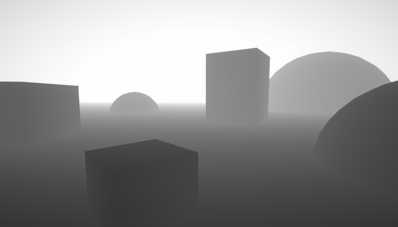
A big post explaining everything about Depth : Depth Buffer, Depth Texture / Scene Depth node, SV_Depth, Reconstructing World Position from Depth, etc.
notably, depth in an orthographic camera is linear
rather than having a 1/x curve
so you can reconstruct a world space depth by just lerping between the near and far clip planes
Can anyone help and explain to my why the rightmost orb is black at the top and not dark brown ?
Nevermind, figured it out. My monochrome part came from a divide and was bigger than 1 at the top part. Using a Clamp node fixed the issue

Values outside the 0-1 range still display as black/white. The divide output likely has values above 1. After the One Minus those are negative, and adding brown isn't enough to push it back into the positive range - so it remains black
Using a Saturate node on the Divide output(s) would clamp the values between 0-1
hah funny,. just edited my post to say that 😄
is Saturate the better option than clamping ?
If clamping between 0-1 yes, Saturate should be more performant. Though after compiling it might end up the same anyway
thanks for the insight. Will use Saturate. I jsut build a shader last night thats a giant mess and after looking at it this morning i figured there might be an easier way ...
And since i have you here right now, i am a bit stumped on how to do this:
There is an area where my color smears into each other, i mean the gradiant part in the middle, i would like to add a noise to it so its not a clear edge anymore, but i have no clue how to do this, i am certain its super simple i am just not seeing it.
Not too sure what you mean by a clear edge, but you can try adding noise (multiplied by a small value) to the divide output
my paint skills are horrible, but regularly the edge is straigth, i want it just a bit more noisy

Also btw, this setup is equivalent to a Lerp so could simplify the graph with that node. The divide output would be the T input, and color properties in A & B ports
Thanks for the advice, fixed that already, i was using lerp before, but ran into the issue and was trying to fix ti with adds to get more steps in between to try to understand what is happening 🙂
this worked, thanks!

hey trying to make a shader here but its generating much brighter than it should be and without the noicse


im stupid I forgot to save
Hello, i am trying to pass the UNITY_MATRIX_I_P and UNITY_MATRIX_P myself to a shader.
I want to do this so i can assure the matrices are not affected by TAA.
When i passcameraData.camera.projectionMatrix or cameraData.camera.projectionMatrix.inverse i do not seem to get the correct result.
Is there anything i am forgetting? this is a full screen shader with render graph.
Should pass the matrix through GL.GetGPUProjectionMatrix iirc
Idk anything about TAA, but Camera.projectionMatrix page also suggests TAA affects that matrix, might want Camera.nonJitteredProjectionMatrix ?
that seems to give a better result already but it's not correct yet, maybe i am using the wrong matrix.
Yeah, i changed that already, cameraData.camera.nonJitteredProjectionMatrix.inverse;

ok i almost got it
cameraData.GetGPUProjectionMatrixNoJitter(0);
This one seems to be correct

but i am getting a different error now
You can only call cameraColorTargetHandle inside the scope of a ScriptableRenderPass. Otherwise the pipeline camera target texture might have not been created or might have already been disposed.
UnityEngine.Rendering.Universal.UniversalCameraData:GetGPUProjectionMatrixNoJitter (int)
heya, I had a bit of a newbie question in relation to texture packing-
I have a pretty simple terrain system and I'm trying to implement frozen/burning/cut grass/etc. states in the form of a grid. that's all working and fine, but the part I'm struggling with wrapping my head around is making this extensible to 4+ states. atm it renders distances to grid cells into a custom render texture that's then passed to the grass + terrain shaders for rendering
my thought is that I could make the CRT a RGBA16 Float format texture, then store extra information in R0-1, R1-2, R2-3, etc. rather than packing and using a second or third texture. but then I'd need to do comparisons & branching in the shader to check "is red > 1, is red > 2, etc." which seems inefficient. then again, so does passing 3-4 textures to shaders and doing a ton of checks there anyway. do any of you guys have experience/tips for something like this?
another idea I had is to store the cell type index (fire = 0.1, frozen = 0.2, charred = 0.3, etc.) in the alpha channel, then use that to inform what to do with the rgb channels. still not sure though
hey, could someone help me with this problem? I would like to make the spell indicator render above the map mesh, I've already tried using sorting layers and even a custom shader, I'm using the Image component but I've tried with Sprite renderer too, the result is the same


You probably want decals. URP has decal projectors
Or you want a shader that draws very late and ignores depth
layers affect draw order too but if it still tests depth it wont work
Does anyone know an easy way to fix a prefeb I imported that is rendering in pink? If I change the shader to use standard instead of URP I can see what it's suppose to look like but not when I set the shader to URP -> LIT it goes back to pink
Urp shaders would only work if you're using urp. If you're using the built-in render pipeline, you can't use urp shaders.
I'm using unity 6, URP 3d but maybe the assets I used were using the old pipeline. I'm not the best at this stuff but maybe there's something I can do to convert the assets to be compatible with urp
If the standard shader was not pink for you, then you're using birp(built-in render pipeline)
Not urp
Maybe when I imported the assets it automatically switched which pipeline I was using
Since I've never manually changed it in setting
Never heard of something like that. Make sure your project is configured to use urp and it should work.
Will get another chance to look at it tomorrow, thank you for your support on this
Hello, i would like to ask how to implement height maps in the shader graph🙌🏻. Im using some textures but idk how to implement the height map
Hi, i am using unity's toon shader 0.10.2 version. And i want the objects to cast shadows to the table. I tried to play with settings but i dont really know much about shaders. Here is the table's material settings.


ok i found that it only works with directional light
Oh, that did it for me too, many thanks! I wasted all day messing about with shaders!
Haha, good to see that someone else is also looking into this style. I have trouble with getting light te reflect on the player sprite though
Are you talking about any light other than directional?
I just tested mine and I can get spot, point and directional lights reflect on my sprite, but not area light
Easiest way would probably be to manually create a mesh of the river but UV map it straight so the scrolling just follows that geometry.
Could also look into the flowmap technique which could let a texture or vertex colours control the direction the texture flows in.
spot lighs and dot lights aren't working
when i'm back at work i need to take another look. the main goal was to add shadows, so maybe i'm missing something
Ok, I got all light types working now! Let me know if you want any of my shader graph settings or anything! I appreciate your help, would love to repay it back 😄
lol, trying to position the sprite to receive all light types at once as well as a shadow from another sprite
(while demoing that I can flip the sprite now thanks to you 😄 )

that for sure would be nice.

The material is the default, new material.
Then I had to enable Debug view in the Inspector on objects that have the Sprite Renderer with the material and check Receive Shadows and set Cast Shadows - On. I'm trying to remeber if I did anything in the URP settings, but I don't think so

Use Fraction node after the Tiling And Offset, and change the Tiling, i.e. to (2, 1)
Use the Ellipse output as the Alpha output of the shader. (If there's no Alpha in the master stack you may need to adjust Graph Settings first. e.g. make the shader transparent or use opaque + alpha clipping)
ah also just in case im wondering if i am going in the right direction 😭
i am trying to make something like a line that is connected but its jambled up and it would change seed (randomly) fast
and i want that line to be inside of the elipse , why i need 2 is because im trying to mimic something like eyes
idk how i could explain it visually but i think i could find something
okay i seem to cant find anything on the internet 😭

something like this im guessing
Probably not easy to do that procedurally. Easiest way would be to draw a texture similar to a flipbook (typically used for animated textures, but each frame could be completely different if you want)
In graph that would just use the Flipbook node with Tile port based on Time. Put into UV port on Sample Texture 2D
ah so back to drawing lol, thanks a lot for the help above, it works btw
never tried the flipbook node before, hope diving in with no doc would be succesfull xD

Might be able to do something like this with Lissajous curves or by looping around with slowly-varying eccentricity, radius, and offset

though would be difficult to translate into shader...
Hello there lads, I tried to make AoE indicator shader, but... shaders so far are magic to me 😅
What I want:
- Highlight intersections of other objects that are inside of my mesh with my shader with color
- Highlight borders of intersections with color
- Shader should work on cubes, spheres, cylinders and cones
- Objects with same material should merge
- Highlight should be scalable with object
So far I managed to do highlight, but works only for spheres, but at least it can scale with objects somehow.
Any help and advice is welcome! :)


Not a bad idea, but you could always just use decals too ;)
Does anyone know why a shader will look incorrect when applied to a sprite, but if I modify literally any value on the SpriteRenderer via the editor, it will refresh and the shader looks correct?
I'm assuming the shader/material is doing some sort of caching which results in the incorrect look, and modifying the game object causes it to force redraw. But I'm having trouble figuring out how to force a redrew at runtime
how large can 2D texture arrays be ? i was going to use a texture atlas but i need to be able to add/remove with modding so im thinking texture array is better option i can compile them far more easily when loading textures
there must be an upper limit to how many it can store right?
Im making a color replacement shader.
this feels pretty inefficient, but I dont really know GPU efficiency all that well.
This is just for the eyes, but I have 12 other colors to replace as well.
Do I really have to do all of this to safely replace the colors?
Color Mask -> Invert B to W -> Replace W with new Color -> Add to new Texture.

it works really well, it just looks like "a lot" lol

Hey, does anyone know why my water shader is in a grid like pattern in URP? Haven't been able to figure it out. I have a Vector2 (WindDirection) which controls the direction of the waves, but they seem to move in a grid instead of a wave.


DirectX 11 has a maximum of 2048 slices for Texture2DArray.
https://learn.microsoft.com/en-us/windows/win32/direct3d11/overviews-direct3d-11-resources-limits
It would be more efficient to make the original colors shades of gray. Then you can simply sample the color, which will be a value between 0 and 1, and use that value to sample a 12x1 texture with your twelve colors in a row.
my shader gets weird when i tilling the texture too much, how can i fix it ? Applied no mipmap, filter mode = none in texture import setting

This happens when you don't have mip maps enabled.
For the best quality in this scenario, you want mip maps enabled, trilinear filtering and anisotropic filtering set to something high.
my shader doesn't work so well with mipmap, even with mip map it is still weird

Do you have trilinear filtering on there? That gets rid of the bands that I'm seeing in this screenshot.
for your specific shader you could just make a distance fog like effect where it fades to grey
Hello, there's currently no way of using stencils in ShaderGraph in URP right? 😁
any good way of getting a per object random number inside a shader that isnt derived from the objects transform?
There's no nodes for them, no. I think there's the possibility of adding it with custom HLSL blocks? Otherwise just use stencils by layers using pipeline scripting / render objects
Hmm, maybe not possible with the custom HLSL block idea. You can create functions, but usually the stencil stuff lives in the header space
alr


im trying to do smth similar
well thats not the part that matters cuz i can do that with my shaders
to be honest.. u could probably just use a flat 2D image.. w/ a gradient edge..
and let the PSX shader ur already using pixelate it
ye
position it over the object and drop the opacity a bit
thats what i was thinking i just dont know how to apply an image to the object
holy, why does it actually look good
1 second and ill show u
no i know what u mean, but do i add it inside the gameobject?
like as a child
it would be a prefab.. or u could put it on the gameobject
i would just position it where the gameobject is
yea how would i put it on the gameobject?
like constantly
sec
ima tryto figure it out
u could have a simple script that did 2 things
- position it to its "Target" u could assign that in the inspector.. or just use it on the same gameobject with
transform
and then 2. it would rotate to align itself to the camera
so its always facing the camera
i think my shaders could prolly do that automatically
hey so i just learned about MaterialPropertyBlock and it seems to be really good and I can't really find any proper downsides to it, im just wondering if its a thing that's too good to be true because that's kinda how it feels, I saw a reddit post that mentioned it is bad for HDRP, which is what my project is using, but no explanation as to why they say that
ya, i believe so too
so u can probably not worry abotu the pixelation and all that
and use regular stuff
yeah, im trying it rn

wait better yet, its more refined if u actually draw it between the camera and the target..
so its always between u and the object ur lookin at

differnt colors for different prefabs


no reason really
to make my screen-grabs pretty? ¯_(ツ)_/¯
ah
you don't actually see them..
yea ik lol
they're only rendered in scene-view
b/c Colors make the world better
for a second


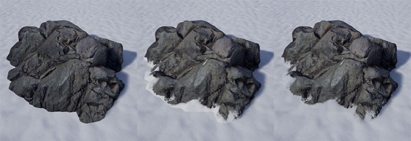
jumpscares?
theres a game called IMSCARED on steam it basically the exact same theme
and i took huge inspo from it
even tho that game uses 2.5d
its
ok
if u wanna continue to show it off as u build it consider making a #1180170818983051344
lowkey im kinda stuck
you'll get told that by someone else anyway
#archived-game-design move over to and yea ill brainstorm with ya
MaterialPropertyBlock is more of a BIRP thing. SRP from what I understand tries to do this process for you
but it's still probably useful for things which don't use the SRP batcher
im a little unknowledgeable in this area, but is it automatically just turned on and being used in the context of a HDRP/SRP?
and in that case if im doing something like editing a material's property should i be storing a new material instance through Renderer.material instead of MaterialPropertyBlock?
SRP batcher should be on by default for URP/HDRP but you can check the pipeline asset to see if it's toggled. As for changing material properties, really you're not expected to work too hard to get things to batch which was a large feature of this 'newer' pipeline.