#archived-shaders
1 messages · Page 103 of 1
Turns out I can make a similar texture if I use Normal From Height on the voronoi node in shader graph. Then, using dot product on that and the XZ plane of the camera and using the absolute of that value gives me this

My main issue with this right now is the shimmering when the camera moves
completely procedural so you can easily make it yourself in shadergraph if you want to test

have to use an orthographic camera
Eyy, if you step that you can get it closer to a strait line I think
may need to mask it a tad better too using A
...why not just use a triplanar node?
Trying to convert a shader from built-in to URP hlsl and my own blocker atm is a function called WorldNormalVector which doesn't exist in URP
Not sure how to fix the shimmering seen in this gif. It seems to be an artifact from the normal from height process
If I draw the value from the voronoi before the normal from height, it doesn't shimmer
I've taken the code for NormalFromHeight directly from the ShaderGraph node.
void Unity_NormalFromHeight_Tangent_float(float In, float Strength, float3 Position, float3x3 TangentMatrix, out float3 Out)
{
    float3 worldDerivativeX = ddx(Position);
    float3 worldDerivativeY = ddy(Position);

    float3 crossX = cross(TangentMatrix[2].xyz, worldDerivativeX);
    float3 crossY = cross(worldDerivativeY, TangentMatrix[2].xyz);
    float d = dot(worldDerivativeX, crossY);
    float sgn = d < 0.0 ? (-1.0f) : 1.0f;
    float surface = sgn / max(0.000000000000001192093f, abs(d));

    float dHdx = ddx(In);
    float dHdy = ddy(In);
    float3 surfGrad = surface * (dHdx*crossY + dHdy*crossX);
    Out = SafeNormalize(TangentMatrix[2].xyz - (Strength * surfGrad));
    Out = TransformWorldToTangent(Out, TangentMatrix);
}
Hi there, quick question. I am having trouble with the CanvasGroup alpha. It doesnt seem to be entirely smooth
the last digit aroung 0.99 seems to stick.
for example 0.99803 will be fine, but 0.99804 will be totally dark. even tho its obvious it could be much smoother.
Here is the output from renderdoc
is it a known issue? I can workaround by putting another image in the canvas group. like this. but Id like to know the cause so I can explain it
I assume there is some rounding issues perhaps?

I also get the same issue with a variable and set it directly from C# using material.SetFloat
thx it worked, the base shader was only because the base shader was already done, but it is way easier with triplanar node 🔥
Hello, I'm trying to play with the Shader from UNity's URP Package Sample called "TrailEffect", where a little ball goes around in some sand and gets a trail by displacing some verticies.
I am completely new to using Shaders and Shader Graph so please bear over with me...
Once I begin to scale the mesh that renders the sand that needs to be displaced, the actual trail effect begins drifting away from where the little ball thats supposed to have the trail effect actually is. How would I solve this?
From what I can understand its a problem with the UV being in local space or something, and not taking the scaling into account, but I simply have no idea how to fix this. What I'm looking for in the end, is just the trail being the same size as now, but the mesh being much larger, so I can use it on the ground of my game since its a pretty cool effect.
Thanks

And I don't understand where to put the Height map and spectacular

Do you mean normal? If its a height/displacement then you may want to be doing vertex displacement instead.
And this is in metallic/smoothness mode so you can swap it to specular (metallic is 1 - specular anyways)

I got the universal pipeline
but i need it for specific few scenes ONLY
but now every new gameobject i make has that unlit thing and i need light to see it
how do i make it so stuff is like before and i can set it to react to light manually
2d btw

Shimmering issue isn't present if I'm not generating a normal map from a heightmap at runtime (i.e. using a prebaked texture). Only issue is, I cannot make a texture that contains the color right values
the generated-at-runtime normal map contains negative values which are crucial for it to work. Any image I make gets clipped to 0..1
You can sample the tex and adjust the vert positions yourself in the shader
a normal map is always in the 0-1 range (as that is how it for all textures) but we adjust it to be -1 > 1 by doing xyz * 2 - 1
this one does have negative numbers though. i assume that's a bad thing normally but for my case it isn't

(what you're saying here is just the fragment shader returning waveNormal.x < 0)
I think in shader graph it expects the input to be 0-1 range at the end
tbh i dont really know for sure 🤔
float RandomFromSeed(float2 seed, float min, float max)
{
    float randomno =  frac(sin(dot(seed, float2(12.9898, 78.233)))*43758.5453);
    return lerp(min, max, randomno);
}

float4 GetPaletteBaseShadingColor(InputData inputData, Light mainLight, float toonLevel, float2 uv, half specular)
{
    float4 col = SAMPLE_TEXTURE2D(_BaseMap, sampler_BaseMap, uv);
    [loop]
    for (int i = 0; i < _TargetPaletteTex_TexelSize.z; i++)
    {
        if (i >= (int)_PaletteLength) return float4(0,1,0,1);
        float texelWidth = _TargetPaletteTex_TexelSize.x;
        float u = (i + 0.5) * texelWidth;
        float4 srcCol = SAMPLE_TEXTURE2D(_PaletteTex, sampler_PaletteTex, float2(u, 0.5));
        if (all(abs(col.rgb - srcCol.rgb) < 0.001))
        {
            float lighting = saturate((toonLevel + 1.0+ _ColorOffset) * 0.5);
            // return lighting;
            float texelHeight = _TargetPaletteTex_TexelSize.y;
            float row = max(0.000001,lighting) / texelHeight;
            float darkerRow = row+texelHeight;
            float distanceToRow = abs(row - lighting);
            bool isOnShadeTransition = distanceToRow < _BaseMap_TexelSize.y * .2;
            float noise = RandomFromSeed(inputData.positionWS.xz, 0, texelHeight);
            float4 color = SAMPLE_TEXTURE2D(_TargetPaletteTex, sampler_TargetPaletteTex, float2(u, lighting + noise));
            float4 highlightColor = SAMPLE_TEXTURE2D(_TargetPaletteTex, sampler_TargetPaletteTex, float2(u, 1.0 -     texelHeight * 0.5));
            float highlightStrength = smoothstep(0, 1.0, specular);
            if(toonLevel > 0) color.rgb += highlightColor.rgb *  mainLight.color * highlightStrength;
            color = saturate(color);

            return color;
        }
    }

    return col;
}


Ive created a texel-based shader which uses palette textures for shading for a pixel art look. The first image is how the shader currently looks, and the second is a manually textured lit shader. Im now trying to get closer to the second image by introducing some noise on the edge of each color band to create a dithering like effect, but I cant seem to be able to figure out how to go about achieving that. How could I identify where a color band is next? and How do I restrict my random to the texel grid?
Ive abandoned the previous idea in favor of bumpmaps, but I cant seem to get them to work. Ive copied everything from the URP Lit.shader file but for some reason its not applying the normal map. If someone could take a look at my files to see if they might be able to spot whats keeping it from working then that would be very helpful.
https://github.com/StijnArts/TexelShaderProject/tree/main/Assets/Shaders/PaletteSwap

GitHub
Contribute to StijnArts/TexelShaderProject development by creating an account on GitHub.
just received this response from the original creator of the effect

sounds like you/we got it
i mean i still have no idea what the math is to "extract the horizontal direction relative to the view"
I assume dot product would be involved, but everything I've tried doesn't seem to give any usable results.
Best I was able to achieve soo far in blender
If i use alpha to reduce the "threshold" of the dot it gets better
A bit better in orthographic

Random question that doesn’t quite a fit a category but let’s say i have a full screen space shader and i have several other shaders i only want to apply to certain layers while retaining depth, how would i
whats the full node setup
here, made with blender 4.2
has the img embedded
how would i go about making a interactive snow layer / mud layer for the unity terrain, as i have done it with a high poly plane but in this use case that will not work
I've been trying to do that as well, and this is how I did it: Make an orthographic camera a distance above the player, and make it render to a 1024 x 1024 R16_UNORM rendertexture. Make a sprite of the player's foot/whatever you want to print in the snow/mud with, and make it be on a layer which is not rendered on the main camera and rendered on your orthographic camera (culling mask). Then, make another rendertexture of the same settings and a compute shader that writes to that texture, accumulating frames by taking the max of the new texture and the texture the camera renders to. Now pass the orthographic camera's projection and world to camera matrices to your shader, and multiplying the projection and world to camera matrices with the world position of each pixel, dividing xy by w and remapping from -1, 1 to 0, 1, then inverting the y coordinate by subtracting it from 1. Now you have normalized UVs that you can use to sample your second rendertexture. You can use tessellation or parallax occlusion mapping, which simulates nonexistent geometry from a heightmap. For a terrain shader, you'll need _Control, _Splat0, _Splat1 _Splat2 and _Splat3 textures, which get passed in by unity terrain automatically. (However, in my case I'm doing it with shader graph and there's a bug where it works fine with other meshes but not with unity terrain, the matrices aren't getting passed in)
I appreciate the reply ill give this a crack
You can round the uvs that you pass into your noise function
alright so one thing I'm trying to figure out is making a texture sampler where instead of inputting a UV value, I can instead input a world position and it'll automatically tile it based on said position. I can do this easily just by splicing the desired axes into a 2D vector if it only needs to be viewed from one angle, but I want to try and figure out how I'd check the normal angle and use the appropriate directions
Maybe I can somehow convert the world position based on the space of the normal's direction, then just get two of the axes. But the only 3D rotation function in shader graph is rotate around axis
alright here's what I made, it's janky as hell but I think it works for now


actually no it isn't
How would I go about making gradient noise that continuously shifts and warps, without actually scrolling? E.g. like how with voronoi noise, you can just continuously change the angle offset lerp to make all the cells shift and squish around each other
Still need help, anyone?


This shader is supposed to fade the top & bottom of this UI tiled image.
But when I use its material, the "tiled" image is only repeated once. Maybe I am overriding the UVs?
Here is without the material:

Any idea on how to use the UI UVs ? 🤔
Looks like it's because of the "one minus": the UV goes above 1 as the image is tiled. But then how can I know the max UV value? 🤔 to substract from it instead
Well I guess I would really just need to get the recttransform's height... if there is no easy way I'll just use a material.SetFloat in a dedicated script.
Everything good for me 👌🏼
Looks like there are some interesting features in the UGUI samples for Shader Graph (exists only since Unity 6000.0.40f1)
Including one for retrieving RectTransform size via a node
Hi guys I imported a map into my unity project (I use the latest version of unity) and some textures are pink but they are not always the same it depends on how he takes them so I searched on the internet how to fix it I installed "Universal RP" and I did the render pipeline converter and most of the textures were fixed instead some tell me that there was an error and that they do not support something written is there a way to fix them permanently or do I have to replace them?
Unfortunately you'll have to open the shader code itself and edit it
an ok ok thank you very much
Hi everyone. Can anyone suggest a good series of free video or text tutorials for writing HLSL shaders for beginners for Unity 6000?
Ive started following a HLSL coding tutorial for beginners on youtube, but then ran into a problem where the suggested code just wouldnt work in Unity 6000 (the tutorial was made in 2021 ). Even more so - I later found out that the tutorial playlist was cut short 2 years ago and is never getting finishes. So Yikes
There aren't many tutorials on that. The best you can do is follow tutorials for specific render pipeline and hope they didn't change a lot since the tutorial version.
Honestly, if you want to learn hlsl, you probably shouldn't rely on unity api
Just look up general tutorials on hlsl
When you learned enough, you'll know how to apply it in unity context.
mmm, mmm, aight. Thank you!
My shaders are missing but they are declared in my ShaderVariantCollection?
but

  - first: {fileID: -6465566751694194690, guid: 3b226546493bb7445b0881cceaaa5adb, type: 3}
    second:
      variants:
      - keywords:
        passType: 8
      - keywords: DOTS_INSTANCING_ON
        passType: 8
      - keywords: INSTANCING_ON
        passType: 8
      - keywords:
        passType: 13
      - keywords: DOTS_INSTANCING_ON EVALUATE_SH_VERTEX LIGHTMAP_SHADOW_MIXING SHADOWS_SHADOWMASK
          _FORWARD_PLUS _MAIN_LIGHT_SHADOWS_CASCADE
        passType: 13
      - keywords: DOTS_INSTANCING_ON EVALUATE_SH_VERTEX LIGHTMAP_SHADOW_MIXING SHADOWS_SHADOWMASK
          _FORWARD_PLUS _MAIN_LIGHT_SHADOWS_CASCADE _SHADOWS_SOFT
        passType: 13
      - keywords: EVALUATE_SH_VERTEX LIGHTMAP_SHADOW_MIXING SHADOWS_SHADOWMASK _FORWARD_PLUS
          _MAIN_LIGHT_SHADOWS_CASCADE
        passType: 13
      - keywords: EVALUATE_SH_VERTEX _FORWARD_PLUS _MAIN_LIGHT_SHADOWS
passType: 13```Hello, How can I solve this to put and Use the Height / Displacement map ? (like in the right picture)

I tried to use this but didn't work or did it well :/
https://learn.unity.com/tutorial/shader-graph-vertex-displacement
Does someone have any tips and tricks, tutorials, whatever, for shaders that work with WebGL?
I'm trying to use Toony pro Colors 2, but I need my lights to be baked, I'm trying to find something that works in this case. Didn't have success with it yet
there needs to be enough verts to displace... Or tesselation is needed: https://docs.unity3d.com/Packages/com.unity.render-pipelines.high-definition@12.0/manual/Tessellation.html
If you don't have enough vertices, you could use tessellation (only works in HDRP) or you could use the parallax occlusion mapping node, which simulates geometry from a heightmap.
i'm in URP
then you'll need to add more vertices or use parallax occlusion mapping, tessellation isn't supported in URP shader graph yet.
Something like this ?

the node outputs parallax UVs, so you should use it to sample your main texture, but if you're using triplanar mapping to sample your main texture I don't think that would work.
pink ball of death (URP)

Hello, have anyone seen a simliar shader to do this effect, is this possible to be done in unity ASE shader editor, its similar like render node in Maya, but I dont remember everything clearly , Any ideas or a simple idea how to do this effect?


I remember seeing a video about rendering sand in the game Journey. I think they had a part about some glitter like effect on the sand.
The video was called: Sand Rendering in Journey
What i understand from the video is that they use a normal map with a lot of noise and then used specular reflection with the normal map.
Thanks , i will take a look
So I would have to recreate a Triplanar Shader by myself, and then after create a height map shader and combine them in 1 shader ?
If so, any tuto on both of them ?
The parallax node with triplanar node doesnt work right out of the box if I recall.
https://i.imgur.com/ZnaUVKq.png
obviously bgolus has the answers

does anybody know how to make a sobel edge finder in shader graphs using nodes?
(BIRP) are these all correct as a "root PBR" sub shader? i'm having weird results w ith some maps so i'm not sure if i'm reproducing their functions right.


pretty much just wiring everything up with a scale multiplier for adjustments if it doesn't look great in the environment. but i'm also pretty clueless as to what i'm doing here.
I can't change the smoothness property of a shader graphs material, yet the guy who's tutorial I'm following is somehow able to do it.

I was told to make a material from the shader in order to get an exposed value, although isn't this what I've already done here? Am I doing this wrong?

aside from that, for a second, why is your 'smoothness' a vector2 instead of a float/slider?
Huh touché let me check what I'm doing wrong here 😆
I didn't notice that
Wait I just realized they're using a "vector1". Isn't that a float?
for all intents and purposes, yes (although someone could probably pull an 'well aktually' on us 😁
I must've misheard it then. Thanks. How would I be able to change this though?

you mean, change it to a float?
no I meant make it exposed, sorry
are you using unity 6?
Yes, 6.1 I believe
oh, i have not used that yet, but in 6, it is already exposed. click on it, in the list where you created it, and then look at the 'inspector' that comes up. sorry for that wrong terms. i rarely use SG. trying to make a SG now, to screenshot
alright.

The guide I'm following just shows an exposed check that I don't seem to have

now, right click on your Shadergraph in the Project. (the one you have a screenshot of that shows the initial material) and Create a new Material. it should be exposed in that
Yep it works it seems. I'm not sure why that's the case though.
it is normal. i do not know the exact details to explain it properly though
Game of find the 7 differences 😭

indeed
Alright, thanks for the help though
I appreciate it 👍
Does anyone here have ny good resources for using unity's built in sky renderer tool?
I have 2 unit vectors, the normal vector of a quad, and the view angle. As the quad rotates, the dot product between the two unit vectors will cycle from 1 to -1 and then back to 1 over a 360 rotation. I want to introduce some value that increases the rate at which this oscillation happens. So, for example, the dot product value will cycle from 1 to -1 and back to 1 over only 180 degrees.
What can I do? Acos to get the initial angle back, multiply it, and then cos again?
[WARNING, LOW POLY GORE]
im so confused over this
i know theres an unneceasrry multiply, dont worry about it
so i multiply white and black by red, the white becomes red and black is unchanged
i then add this to the original texture to replace the white with the red, while not affecting the black, however this simply results in a white color, despite the destcolor value being red

could anyone explain why this happens and how i can fix it
Hey yall I have a simple question regarding HLSL code in Unity, I wanted to utilize just the G channel of the UV being used on an object, how would I go about calling that in shadercode?
I'm experienced in shader-graph but I wanna do this specific thing in unity's shader code, can't seem to find a good answer online for it
uv.y?
Hi there, thank you for responding, it seems to be saying undeclared identifier 'c' at line 39, which is the line at the bottom there that is for the alpha

c.a seems to be incorrect but I'm totally confused haha
Im basically trying to create a gradient lerp on a material
I know the UV might be correct
idk what's going on haha
I'm not seeing any declaration of c here unless it's supposed to be global in scope
I think you mean color
hm alright, so how would I declare C?
I declared alpha as color.a as the A channel of it would be 0

hopefully
The error is gone but now the material is appearing error magenta
Could it be because I lerped the color incorrectly?
This is a surface shader, which is only valid on the built-in/legacy render pipeline. Such a shader in URP or HDRP will appear magenta.
Oh thank you
So what type should I use then?
URP and HDRP shaders do not have an equivalent to surface shaders currently. Surface shaders make it much simpler to write shaders that support lighting. In URP and HDRP, you have to implement a lot more boilerplate code just to get lighting working.
If you don't need lighting, it's simpler to write an unlit shader.
Damn you're kidding right?
That's annoying
I need it to have shadows basically
over the grass
Is it not possible to do with Shader Graph?
I have a very unique issue, you see in shader-graph in what I'm working on, we have a lineart shader that excludes line-art by the alpha channel of the surface
now we can't go and make all the grass transparent for performance reasons
But I was told in shader code I can make a grass shader that has an alpha of 0 passed through the color channel
does anyone know of a shader for viewmodels for urp?
Problem is I need lighting on the grass
Is there a way I can make an unlit shader detect a shadow over top of it, and make the object darken in turn?
I see. So it sounds like in an ideal world, you'd just be able to output an alpha value in an opaque shader in Shader Graph and avoid code entirely? Or do you prefer to do this in code?
I've tested for close to a week now to get the alpha value to change in Shader-graph
I've asked a senior tech artist on the matter and he says it's likely it'll need code
Lighting is more than just implementing shadow. Are you sure you don't need more than just shadow support?
Trust me just shadow support will do
we need soft stylized grass that goes by a linier gradient
I've achieved this in an unlit shader in code already, basically all it needs is the ability to detect shadows and darken the whole object in turn
The whole object? Are you referring to individual blades of grass?
basically yea, ideally precise shadows but the whole object would do too
basically all it needs is to draw a shadow on this unlit blue plane

This is URP?
This is using URP yes
The reason I want it to just detect shadows is because this is being built for low spec hardware
I don't know off the top of my head how to sample shadows in URP, but from searching the source shader code, this seems relevant.
https://github.com/Unity-Technologies/Graphics/blob/master/Packages/com.unity.render-pipelines.universal/ShaderLibrary/Shadows.hlsl
hmmmm idk what half of it does
Can you post your unlit shader code?
{
    Properties
    {
        _Color("ColorA", color) = (1,0,0,0)
        _ColorB("ColorB", color) = (1,0,0,0)
        _Position("Position", Range(0.0, 1.0)) = 0.5

    }
    SubShader
    {
        Tags { "RenderType"="Opaque" }
        LOD 100

        Pass
        {
            CGPROGRAM
            #pragma vertex vert
            #pragma fragment frag

            #include "UnityCG.cginc"

            struct appdata
            {
                float4 vertex : POSITION;
                float2 uv : TEXCOORD0;
            };

            struct v2f
            {
                float2 uv : TEXCOORD0;
                float4 vertex : SV_POSITION;
            };

            float4 _Color;
            float4 _ColorB;
            float _Position;

            v2f vert (appdata v)
            {
                v2f o;
                o.vertex = UnityObjectToClipPos(v.vertex);
                o.uv = v.uv;
                return o;
            }

            fixed4 frag (v2f i) : SV_Target
            {
                // Creating Gradient

                float4 col = lerp(_Color,_ColorB,i.uv.y * _Position);
                return col;
            }
            ENDCG
        }
    }
}```Here you go :)
This one 100% works n stuff, just doesnt recieve shadows haha
So, there can be a lot of added complexity when adding shadow support because of how many different options there are. Hard shadows, soft shadows, shadow cascades, screenspace shadows, shadows from additional lights.
You can simplify your shader if you don't need all those things.
So I think all you need is to call TransformWorldToShadowCoord from Shadows.hlsl to get the shadow coord, and then pass that into MainLightRealtimeShadow. Then you'll get back a shadow attenuation number, 0 for full shadow, 1 for no shadow, which you can multiply with your col.
hm alright
I'm very new to shader code, most of my experience is using shader-graph, could you give me an example of how this would be done?
Shader "Unlit/sdr_UnlitTest"
{
    Properties
    {
        _Color("ColorA", color) = (1,0,0,0)
        _ColorB("ColorB", color) = (1,0,0,0)
        _Position("Position", Range(0.0, 1.0)) = 0.5

    }
    SubShader
    {
        Tags { "RenderType"="Opaque" }
        LOD 100

        Pass
        {
            CGPROGRAM
            #pragma vertex vert
            #pragma fragment frag

            #pragma multi_compile _ _MAIN_LIGHT_SHADOWS _MAIN_LIGHT_SHADOWS_CASCADE _MAIN_LIGHT_SHADOWS_SCREEN

            #include "UnityCG.cginc"
            #include "Packages/com.unity.render-pipelines.core/ShaderLibrary/Shadows.hlsl"

            struct appdata
            {
                float4 vertex : POSITION;
                float2 uv : TEXCOORD0;
            };

            struct v2f
            {
                float2 uv : TEXCOORD0;
                float4 vertex : SV_POSITION;
                float4 shadowCoord : TEXCOORD1;
            };

            float4 _Color;
            float4 _ColorB;
            float _Position;

            v2f vert (appdata v)
            {
                v2f o;
                o.vertex = UnityObjectToClipPos(v.vertex);
                o.uv = v.uv;

                o.shadowCoord = TransformWorldToShadowCoord(mul(unity_ObjectToWorld, v.vertex).xyz);

                return o;
            }

            fixed4 frag (v2f i) : SV_Target
            {
                // Creating Gradient

                float4 col = lerp(_Color,_ColorB,i.uv.y * _Position);

                float shadow = MainLightRealtimeShadow(i.shadowCoord);

                col.rgb *= shadow;

                return col;
            }
            ENDCG
        }
    }
}
*edited to add keywords that Shadows.hlsl expects the shader to define.
URP has a shader library with a bunch of variables and functions for common functions, like lighting, that all the built-in shaders and Shader Graph use. We're using that here for our own shader.
Right I understand
Also note that you've started with the legacy unlit shader template, that has a slightly different syntax than URP shaders use. But it should still work.
Just getting it copied in now to see it in action
I haven't tested this. Very likely some issue with it. Just let me know.
It seems to be serving an error that it cant include file "Packages/com.unity.render-pipelines.core/ShaderLibrary/Shadows.hlsl"
Im guessing this is on my end
No, that's my mistake. The path should be:
"Packages/com.unity.render-pipelines.universal/ShaderLibrary/Shadows.hlsl"
Oh lemme give it a go then
Alrighty I put it in, it seems to recognise it but it spat out another error and about 5 warnings
Let me see the error and warnings

Ok, so now we're running into a problem with the legacy syntax conflicting with URP shader files. When you use CGPROGRAM, it automatically includes a bunch of legacy functions that are needed for legacy shaders. It must have its own function named PackHeightmap that conflicts with the one Common.hlsl defines.
I would take a look at the URP unlit shader template as your starting point.
https://docs.unity3d.com/6000.2/Documentation/Manual/urp/writing-shaders-urp-basic-unlit-structure.html
I'll leave it as an exercise for you to move the relevant code from your current shader to the new template.
No, this template is like the unlit shader template you started with.
Hello, someone can tell me how to add a Texture2DArray into a custom function please ?
I'm using :
    Texture2DArray TexArray,
    SamplerState Sampler,
    float2 uv)
{
      float3 uvw = float3(uv, 0);
      spectrum[0] = SubScenes.Sample(SamplerTexArray, uvw);
}
But I have the error :
'SelectViewDefault_float': cannot convert from 'struct UnityTexture2DArray' to 'Texture2DArray<float4>'
I can't find any tutorial or stuff on google

Shader Graph uses custom structs for passing textures. Your function needs to define a UnityTexture2DArray instead of Texture2DArray and UnitySamplerState instead of SamplerState. The functions you call on them are still the same.
Hmm alright, so I tried implementing your shadow solution with the template you gave me
and adding the lerp color thing
seems to be returning an error

Okay thanks, but do you know the include needed ? Because the type doesn't exist : s
I don't think one is needed. What is the new error?
You might get an error in your IDE because it doesn't know this function will be within the context of a shader graph, where these types are defined
yes that was exactly that, I trust too much x) Thanks!
Hmm, there must be another include file Shadows.hlsl expects to be included before it, where this LerpWhiteTo function is
Right, I see
Try adding #include "Packages/com.unity.render-pipelines.core/ShaderLibrary/CommonMaterial.hlsl" above the Shadows.hlsl include.
(hopefully this won't be a long rabbit hole of new errors and new include files)
It fixed it! One moment for me to fix another error I know I caused lmao
So I had a question, where do I actually put the o.uv = v.uv;
o.shadowCoord = TransformWorldToShadowCoord(mul(unity_ObjectToWorld, v.vertex).xyz);
in this new template
Basically I cant define the UV or shadow coordinates for the final color stage
You need to define the uv in the Attributes struct, which is the equivalent to the appdata struct in your first shader, then do the same in the Varyings, which is the same as v2f.
It's the exact same thing in fact, it's just a different naming convention that URP/HDRP started to use.
Right I see thank you
My apologies for all these issues
youve been a massive help so far in helping me understand this
Don't worry, I fully expected this going into it. This is the normal workflow when working with shader code, especially SRPs. Resolving compile errors until things start working.
Right I understand, alrighty so I've attempted putting it into the attributes and varyings, it doesn't seem to like the o. structure on it
At least I think
The vert function in the URP template decides to call its output variable OUT instead of o. Have you accounted for that? It can be named whatever you like, as long as its consistent.
It keeps throwing syntax errors so it must be how I'm writing it
I have not
I will fix that
            {
                // The positionOS variable contains the vertex positions in object
                // space.
                float4 positionOS   : POSITION;
                float2 OUT.uv = v.uv;
                float3 OUT.shadowCoord = TransformWorldToShadowCoord(mul(unity_ObjectToWorld, v.vertex).xyz);
            };

            struct Varyings
            {
                // The positions in this struct must have the SV_POSITION semantic.
                float4 positionHCS  : SV_POSITION;
                float2 OUT.uv = v.uv;
                float3 OUT.shadowCoord = TransformWorldToShadowCoord(mul(unity_ObjectToWorld, v.vertex).xyz);
};```This is how I've structured it
Seems to be throwing a syntax error at line 46 which is 'float2 OUT.uv = v.uv;' in the Attributes section
If you look at the original shader you had, I think you'll notice a big difference in where the code is placed. Remember that Attributes is the same as appdata and Varyings the same as v2f.
will do
There shouldn't be any massive structural changes between your original shader and this new one. Mostly just some renaming.
I see the difference
            {
                // The positionOS variable contains the vertex positions in object
                // space.
                float4 positionOS   : POSITION;
                float2 uv : TEXCOORD0;
            };

            struct Varyings
            {
                // The positions in this struct must have the SV_POSITION semantic.
                float4 positionHCS  : SV_POSITION;
                float2 uv : TEXCOORD0;
                float4 vertex : SV_POSITION;
                float4 shadowCoord : TEXCOORD1;
};```this is the fixed version now
This part looks good
            {
                // Declaring the output object (OUT) with the Varyings struct.
                Varyings OUT;
                OUT.uv = v.uv;
                OUT.shadowCoord = TransformWorldToShadowCoord(mul(unity_ObjectToWorld, v.vertex).xyz);
                // The TransformObjectToHClip function transforms vertex positions
                // from object space to homogenous clip space.
                OUT.positionHCS = TransformObjectToHClip(IN.positionOS.xyz);
                // Returning the output.
                return OUT;
}```i've tried adding the final part into varyings vert
It says it cannot define v.uv, is there another way to write this in syntax much like o.uv
would it be VERT?
Definitely feels like we're super close haha
The original shader was reading from a variable called v. That was a parameter into the vert function. Now, the parameter is called IN.
thank you
Also note how the vertex variable that was in appdata has now been renamed to positionOS in Attributes.
Yes yes, fixing that now, seems to work
            half4 frag() : SV_Target
            {
                // Creating Gradient

                float4 col = lerp(_Color,_ColorB,IN.uv.y * _Position); //

                float shadow = MainLightRealtimeShadow(shadowCoord);

                col.rgba *= shadow;

                return col;
            }
            ENDHLSL
        }
    }
}
This is the last part
at line 82 float4 col = lerp(_Color,_ColorB,IN.uv.y * _Position); it's saying "undeclared definer IN"
Which I'd assume would be from the 'IN.uv.y'
How was the original shader accessing the UV?
i.uv.y
And where was i defined?
fixed4 frag (v2f i) : SV_Target I believe
The template shader has not been very helpful here. Since it doesn't need anything from the vertex shader, it doesn't even bother to define the Varyings parameter in the function.
So the fix is
half4 frag(Varyings IN) : SV_Target
Right I see
Alrighty so now it looks like this
            half4 frag(Varyings IN) : SV_Target
            {
                // Creating Gradient

                float4 col = lerp(_Color,_ColorB,IN.uv.y * _Position); //

                float shadow = MainLightRealtimeShadow(shadowCoord);

                col.rgba *= shadow;

                return col;
            }
            ENDHLSL
        }
    }
}```
it's throwing this error now
Line 84 is float shadow = MainLightRealtimeShadow(shadowCoord);
It might help to understand that we are calculating the shadowCoord value in the vert (vertex shader) function, putting that into the Varyings, which then gets passed into the frag (fragment/pixel shader).
Just like the uv, if you want to access the shadowCoord, you'll find it in the Varyings IN parameter you just added. IN.shadowCoord.
Alrighty, one moment :) lemme get that sorted
WOAH
IT WORKS
THANKS
DO YOU HAVE A VENMO
Thanks is enough 😌
Well thank you very much, I've learnt alot about shader code tonight
my co-workers will be very happy to hear we've solved the grass issue
I'm a total noob developer, and I'm using AI to build most of my game.. I got pretty far, but now i want to smash my head through a window... i'm using the built in/standard pipeline, and i want to create a little slime puddle on the floor, and i have this custom shader, but it just seems impossible to receive any shadows!.. I am also using free Unity.. can you please point me to a custom shader that has shadow receiving working so i can take that as a start and modify it to what i need rather than starting from scratch and now wanting to kill myself?
Use shader graph to make a custom lit shader without too much difficulty.
It's usable on built in, urp and hdrp
ah the perils of using AI
Hi again... A simple question (I think I got tricked). Is it possible to send an "array" of RenderTexture to a shader? I have X camera filling X RenderTextures (I can have a max). My previous shader was asking for 13 Rendertextures as inputs, and I read something like I could use a Texture3D. Is that true ?
Or do I have to revert my changes and stay with a stupid huge code ? x)
You can render at several RenderTextures simultaneously. This feature is called "Multiple Render Targets - MRT"
Never heard of it :0 I'll take a look thanks
Well it's limited to 8 on my side, and Keijiro sample don't use an array but several textures. So let's forget about it for now.
RenderTexture can be a texture array if created through code, by setting it's .dimension to Tex2DArray. And volumeDepth would control the number of entries/slices.
In shader should be able to treat that the same as a Texture2DArray / UnityTexture2DArray in ShaderGraph.
But you'd probably need to change how you fill them. i.e. if using CommandBuffer.SetRenderTarget there's an overload with a depthSlice index.
Ohhh intriguing thanks !
Unity probably won't allow me to set it as a texture2array, but if the data is contiguous that's fine too.
Heya, just wanted to ask one last thing, it seems that I cannot paint this material onto a terrain asset with it on a grass blade in a prefab
Would you know what that means by any chance?
Do you get an error?
I solved it :)
Thank you for responding nonetheless
Any idea why my shaders look square?
Also everything looks kinda weird(the thing below the radio)

You mean the ambient occlusion? Unity likes to enable it on new projects, so check your post-processing on the volume and the URP pipeline asset to disable it
Thanks, i'll try that when i get on my pc
To be fair, I think in the standard pipeline it works. But in the last HDRP everything is broken.
Lets say i have a plane facing away from a lightsource placed inbetween a light source and the camera, can I invert the normals so that the plane is effected by the light behind it ?
Why not just rotate the plane?🤔
Inverting the vertex normals would have the same effect
I need the rim light(made with a custom normal map) to be effected by the spot light behind it which doesnt work (in the image i placed some point lights arround the player to get the effect)


Well, I don't think that's gonna work. It might break something too.
You might need to write a custom shader that does the correct calculations taking into account the directions of the light, camera and normals
Thats too conplex for me, i didnt even manage to recreate the default urp simple lit shader
Well, what you're trying to do is quite far from common rendering techniques, so you need to have some experience in computer graphics to achieve the desired effect
Making a custom urp lit shader without graph is kinda hard anyway, I only ever found 1 good example and it needed fixing.
Perhaps with graph you can just use a mask to invert normals for the rim light area.
I do have some but I cant recreat the default urp shader as that is far from some experience, that need all the experience
In the first place, are you sure you need a lot shader there?
what is an lot shader ?
Lit. Was a typo
@woeful breach I used these examples in the past but one needed a small fix to work:
https://github.com/Cyanilux/URP_ShaderCodeTemplates
For the rim lit parts i think you calculate the lit result for both sides and keep the brightest to achieve the effect you desire 🤔
somehow unity themselves cannot provide a lit urp example
I need a lit shader othwerwise the player will jsut look completley out of place
thanks
I'm trying to offset vertices of a high poly plane as terrain, and I want to have a camera render a heightmap of the scene (to the depth of a rendertexture) and I'm wondering how I could sample a depth-only rendertexture in shader graph, because if I use the red or alpha outputs of sample texture 2d lod, subtract it from the orthographic camera's height and use that as terrain height and transforming into object position the terrain is displaced uniformly and moves with the scene camera? (I'm using HDRP and I have tessellation maybe that's causing the issue.)
hold on, i don't have any global volume
Check the URP pipeline asset then, and it should also have a renderer asset that contains full-screen shader / custom pass effects which it's probably included on
this thing? also the PC_Renderer asset?
found it

i really really need help im following a brackeys tutorial and i did exactly what he did except for the fact that he has the fragment part with rgba unlike me with rgb only so i put the alpha in the other part. the outline looks like that tho and i have no idea why cause ive never worked with shaderss

You can use a split node to input your alpha
E.g. split rgba and take a -> output alpha
It's easier in code but you know now you can split a vector into it's components!
Yo, I don't know if this problem has a solution but I have a paralax occlusion stone wall texture that I need to apply to some walls but am not about to handle UVs, so obv do triplanar but as far as I can tell you can't do both of them at the same time. Does anyone know how I can work around this issue? I am using unity version 2022 lts
I couldn't find anything online and what I did find said this wasn't possible
Hello Unity gang, I am curious as to why I keep getting this issue.
Shader error in 'Shader Graphs/Lit': 'PBRDeferredFragment': cannot convert from 'struct v2f_surf' to 'struct SurfaceDescription' at V0.1/Library/PackageCache/com.unity.shadergraph@14.0.12/Editor/Generation/Targets/BuiltIn/Editor/ShaderGraph/Includes/PBRDeferredPass.hlsl(145) (on gles3)
Theres another error to it but way too long to post the text.
I have tried to look through the graph inspector within the Lit shader and can not seem to figure out what it is.
Image
First thing you should do is upgrade your Unity version and all of your packages to the latest available version.
all packages are good but would it really be because i didnt update to the recent 6.1 unity? im using 2022.3.60f1 unless there is an update there..
yeah everything is up to date
no I don't mean major version upgrades.
just having the latest version of 2022.3 e.g.
i believe i do have the most recent one
ive been told to wipe the library folder now waiting for it to regenerate.
anyone know how to do this? I just want to sample a depth-only rendertexture in shader graph.
I tried to use readpixels to make it into a rfloat texture2d, but it still didn't work.
fixed, I used a compute shader to write the depth to another rendertexture
hey lads, before I finish this abomination, I just wanna know is there a way to replicate this effect on a curved surface using shaders?

a normal map? How many tris is it?
Hello does anyone have an idea on how to fix this lit shader?
Shader error in 'Shader Graphs/Lit': 'PBRDeferredFragment': cannot convert from 'struct v2f_surf' to 'struct SurfaceDescription' at V0.1/Library/PackageCache/com.unity.shadergraph@14.0.12/Editor/Generation/Targets/BuiltIn/Editor/ShaderGraph/Includes/PBRDeferredPass.hlsl(145) (on gles3)
Theres another error to it but way too long to post the text.
What I’ve tried:
deleting and letting the library regenerate.
Looked around within the shader and can confirm the errors come from it but why? Unsure.
Make sure your render pipeline and shader graph packages are updated to the latest supported version on that editor version.
Though, it seems to be targeting the built-in rp, which I heard unity is phasing out from, so maybe upgrade to one of the scriptable render pipelines.
Bake the pattern down to a normal map, it will require making a lower poly version of this structure. Bake it down using Marmoset Toolbag 4 or Substance 3D Painter
Then uv the low poly structure to use this new normal pattern
though I would personally reccomending using Substance 3D Designer and making the pattern as a procedural tileable material, then placing it onto your low-poly object to save texture memory, it also means you can re-use that tileable texture across other assets that look like that
sorry for the late reply, its about 2k vertices if thats what you're wondering
thank you!
blender can do normal map baking
Oh? Thats a good alternative then
but yes its often best to use a normal where possible for extra detail and use geometry where needed.
I would still reccomend making a tileable normal map though as it saves texture memory in the long run if you have alot of different structures that would use that pattern
Its a little weird to do but it works decently when you get used to it
well, the game's in a confined space for repeated amounts of time so I guess I would go with which process is the shortest or easiest
Both take a bit of time to do, baking can be tricky and is prone to artefacts
and making a tileable texture requires learning a little bit of substance designer or a related program, which can also be tricky
Tbh it doesn't look too bad detail wise. If lots could be rendered at once (e.g. overdraw) though then you may want to use LODS.
though truthfully, if your game is in confined spaces 99% of the time you could reduce the bricks to be seperate meshes on the same obj, then place them over the top to reduce the amount of polygons you're using, then just use the mesh like that ingame with LODs at long distance
you could probably get away with it if it's an important detail you'll be looking at up close, just be mindful of how many tris are being rendered at any given time
occlusion culling is your friend
ngl theres a lot of these stuffs I need to learn
Occlusion culling is great, tricky to implement though in certain games
I couldnt keep up with probably 50% of the conversation lol
If its indoor stuff that is all pre made then should be a good application
it is!
thank you!
are you a junior dev?
not quite, I usually do the codings and flows of the game
this is my first time doing textures for this team
so a junior on the VFX/Shaders the like
ah right, well I'm quite experienced in PBR textures and I have a fair bit of experience in unity shadergraph so feel free to ask questions anytime
thank you mate
I will definitely return with more questions, so I appreciate your help
have a great day to you
you too
Any idea how to do this or a video with guidance sorry I’m pretty new to unity but I really appreciate the input.
https://docs.unity3d.com/6000.2/Documentation/Manual/urp/InstallURPIntoAProject.html
we work with doc pages in the dev world
Does anyone have any idea how to fix this? @prime coyote you said you were good at shader graph, do you know how I would go about fixing this?
I'll get back to you tomorrow :) It's quite late for me
Dm me what you're trying to achieve and ill take a look
Oh fair enough, thanks
Hey guys is my subgraph too big?

I will try this I appreciate the input
This shader makes all materials completely transparent except when there's an object behind it. I'm following along this video and I'm pretty confused about why
https://www.youtube.com/watch?app=desktop&v=kfM-yu0iQBk

Pastebin
Pastebin.com is the number one paste tool since 2002. Pastebin is a website where you can store text online for a set period of time.
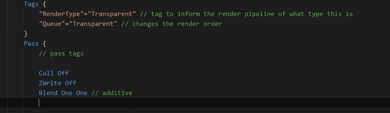
So you have additive blending and you don't write to depth, but I'm not too sure why additive wouldnt render over the skybox
Yeah that's what's confusing me
oh you're using blending with opaque
If you want transparency/blending then you want:
"RenderType"="Transparent"
ZWrite Off*
They don't seem to have the same issue as me though in the video


What does additive opaque even mean though. It's just overdrawing I would expect
That also didn't fix it

I'm not sure, but their thing seems to inexplicably work and mine seems to inexplicably not work
I'm using URP
followed it step for step still same errors.
what unity version and is shader graph + urp up to date? What targets does your shader graph shader have?
Yes later on, but I still don't have the same result before then.
2022.3.60f1
yes both are updates

change this to be Universal only

look at 2:44:45ish in the video
They had a different result compared to me
The only thing I can think of is at the bottom of the material you can override the queue
transparent I think is 3000
oh that worked LMAO

if i try to delete the other or any of the two (HD / Built in) i get

huh wtf is happening with this 😐 something is very broken perhaps with this asset
is the stack for this "value cannot be null" log from shadergraph?
@ebon basin Does the render queue in the inspector correspond to the queue tag?
console
if i try to - it it does not allow me
I think when you create a new material with the shader it will default to the tag value, but the slider on the material will override the tag value

Yep just tested it, that's what it seems to be. Thanks!
my last idea is to close proj, delete Library folder and re open (this makes everything re import)
ive done that first
sadly
the only thing i can think is its something with the asset pack ive gotten this medival lowpoly one
Is ShaderGraphs/Lit your own shader?
it seems to occur when i add in stuff from that.
no
somehow just ended up with it from assets i assume or an asset is using it
Can I create new functions anywhere in the HLSL portion of the shader script?
i did have to click URP 17 for this one asset pack
like import the asset pack, then click URP 17 then import that,

has to be this one using that
If there is a shader called "Lit" delete it and see if thats the cause
You can try re making it or replacing it with a normal urp shader
If the materials that used it are broken that is (if they are not i guess its all fine)
i am trying a suggestion from Claude quickly.
Select your camera in the hierarchy
In the Inspector, find "Rendering Path"
Change it from "Deferred" to "Forward"

This works because shader graphs for the Built-in RP generally have better support for the forward rendering path.```same issue :p
think im going to switch it to a standard one, but is it possible to come back to this and try and fix it down the line or something more urgent now?
Ha its speaking absolute bullshit
lol
urp was gonna be forward by default so
it had the exact directions right but i guess so lol
i think its my splines tbh
i see my splines using Shader Graphs/Lit
I found some ArnoldStandard ima try.
makes it look like a glass road but meh.
The main URP shaders are Lit, Simple Lit and Complex Lit
still not great if one is broken as it should not be
it built.
it works but my road looks like a mirror lols.

oddly builds and all physics work just the looks lol.
those arnold shaders are not really good to use so you should still try to fix the issue/ swap to another urp shader
np np
one more question, i dont need any samples from the Shader Graph hmm?
that would be like the last thing id assume. i know i do with a few other things.
samples? nah i see no reason you do with that error
ahh okay. well ill try to keep looking for examples
okay well.. I have selected the URP / Terrain / Lit Shader and it seems to work, it looks different but its working and im still technically using Lit.
waiting for the build so not 100% on the working part.
works 🙂 thanks
how do I get the scene color in a fullscreen pass in shader graph in HDRP?
I tried using the HD SampleBuffer, the HD Scene Color and the Scene Color nodes. All of these return black. I also tried setting the target color buffer to 'Custom' and using these nodes, then reading from the custom buffer from a second shader and this does also not work.
Does anybody know how to displace a texture so it has a wiggle effect on the uv?
Are you sure your shader executes after something is rendered to the scene color render target?
its a problem with the unity version, if i upgrade it works.
Apply a wiggle effect to the uvs before sampling the texture🤷♂️
Which shader is the best for performance on mobile in URP? (lit)
simple lit
there is also a specific shader for lightmap only lit stuff
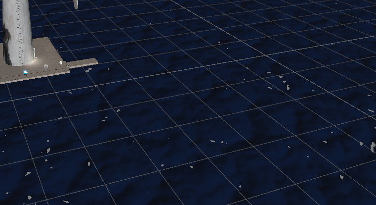
I'm trying ot fake some planar reflections, where the boxes above ground are solid, they have a mirrored version beneath which is alpha tied to negative Y.Is there some way I can still deph test these so that I'm not seeing all of the resultant faces ut more of an actual reflection feel?

i've tried depth write on/off and different depth test modes (using shader graph)
Tbh i feel like using a second camera to capture and render this would be easier. Otherwise you need the "floor" to be semi transparent and to perhaps use the stencil buffer to make the bottom objects only be visible through the floor.
Let’s talk workflow.
If I want to add something like a universal outline to all the player and enemy models,
Enemies can have an eye animation shader as well as a disintegration effect
Players have an animated effect of their own
Would it be better to
A). Create my own PBR sub shader, create the outline shader as a sub shader that also uses the PBR sub shader. Then create an enemy shader that can enable the eye animation feature variant or not, disintegration effect is built in for the death animations
Player shader would be a derivative of the outline shader with the LED pulse effect as a variant feature also
Or B). just make 2 shaders and copy paste the outline effect?
Feels like you have to recreate all the parameters in sub shaders anyway
trouble is I'm in EXTREMELY limited resource environment and need to go for the cheapest possible way
a second camera can be cheap if you render at a low resolution
I dont' know much about stencil buffer, could it be used to render them opaque, put them on top of floor and blend them out on height?
mmmm, in URP I've found any additional camera whatsoever adds at least 1ms, and that's just on cpu
stencil buffer would be used to only make them draw where the floor had already drawn
like, as a way to put them on top? Sorry not sure what the stencil buffer would be doing here
Just a way to make sure they only draw where the floor is (so they arent visible elsewhere)
You probably need a shader that will adjust the colour on the "reflected objects" to get more black the deeper it goes from the floor
to fade it out you mean, would there be a difference between going black and using additive vs using the alpha value

No. You can rewrite the function in your shader.
Yep I just did, thanks.
oh sorry thought you said shader graph
i really cant have HDR color in a sub shader? so if i want emissive map i have to duplicate it in every shader graph?
hi!
I have a flat shaded mesh that I displace with a height map. the base color is just flat white.. what are the dark spots I'm getting there? its like everything that's a bit lower is extremely dark from the Y 0 downward
what is that and how do I avoid it? (HDRP Lit)

when I turn off AO it's just completely black below Y 0


wth. when I place my object at 0, -255, 0 and add 255 to the displacement Y, the dark spots are gone. wth is this. when I get far enough away it disappears too

would it be better to cram all my effects into standard shaders per model type and keep it all to one material, or add support shaders like "outline" as secondary materials?
For BIRP it was common to do it that way, but with SRPs it's encouraged to try to keep it all together and use subshaders/passes.
not that you can't use multiple materials, with one for outline, but the inspector complains to you about it ;p
it was common to do it which way?
and yeah i'm on BIRP
Common to have an outline material instance you shared among other assets. There's also render objects you can apply to them via layer, or post-processing
having a really tough time finding a good outline shader tutorial for BIRP. its all URP
thats the closest i can get it based on the URP methods

gets messy any larger than that
There shouldn't be any difference in the code to that of BIRP or URP. I would even expect the shader graph tutorials to work just fine too
the cleanest looking one leveraged scriptable renderer stuff
looked like a URP only thing

🖍️ Explaining multiple techniques for rendering outlines and highlights for real-time applications. This includes vertex object-space as well as screen-space methods. This can be used to render outlines in Unity or Unreal. Outlines can be used for gameplay reasons or aesthetics.
well, define 'good'.
most common outline shader in BiRP is using additional pass to render a flipped 'shell' using vertex extrusion.
another one is using post process. There should be a plenty of those in the internet
HDRP UV Light Reveal Effect – Help Needed
Hey, hey, and hey!  🖐🏻
🖐🏻
I have no idea why, but I feel like I’ve been struggling with a massive issue for a few days now.
Maybe it’s super simple for some of you, but I just can’t figure it out...
Goal:
How do you achieve an effect in Unity HDRP (yes, HDRP – not URP or Built-in!) where symbols or markings only appear under UV light, like a blacklight effect?
I've seen tons of tutorials for URP or legacy pipelines, but HDRP seems way less documented when it comes to this.
** What I’m aiming for:**
I’m trying to get an effect like this → (screen)
Basically, you shine a UV/spotlight and see hidden patterns or symbols appear only where the light hits.
** What I need:**
Any advice, Shader Graph tips, HLSL tricks, examples, or keywords I should search for.
I’m totally lost on how to make this work the HDRP way.
 I’ll pay in prayers to the Great Gaben so your projects sell like crazy and never get review bombed.
Thanks from the mountain! hehe

what kind of shader do i need to make a hole on a mesh?
Can you link how it's done in URP?
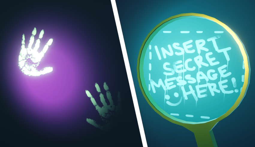
Examples for revealing invisible objects (especially decals, such as fingerprints or hidden messages) based on lights, stencils and other masking methods
"Using Light Colour"

Lol that's awful 😄
Yeah I'm sure you could read the light color in HDRP as well. Dunno if there's a convenient node for it
I'd probably do something with the stencil buffer instead but shader graph can't work with that
Honestly, I’m pretty average when it comes to shaders — this is actually the first time I’ve had to deal with them more seriously.
If you know how to do it, have the time, and are willing to help, could you maybe explain it a bit more?
If it’s not too much to ask, maybe you could even show a simple prototype?
Most of my shader work is done in compute so I'm not too familiar with the specifics of this API either
That said I think the URP solution might just work. Have you tried following it?
HDRP and URP in Unity, at least when it comes to this specific issue, are like fire and water — completely different lighting systems. In my opinion, they work in fundamentally different ways and are about 90% incompatible.
Unfortunately, I’ve tried.
Are you using deferred rendering?
I don’t really know what that is, but of course, if it’s important, I’ll check it out.
What does it affect?
In forward rendering you handle lighting in the fragment shader directly. In deferred rendering, the fragment shader writes its information to the G-buffer and there's a fullscreen pass that handles all the lighting in one go
So in forward you'd have access to all the lighting information in the fragment shader but not in deferred
The one thing I know about shader graph though is that it's incredibly limited. You might want to grab Amplify: https://assetstore.unity.com/packages/tools/visual-scripting/amplify-shader-editor-68570
Alright, I get it. But like I mentioned, I’m not very strong in this area of programming.
I’m mostly looking for info like “someone already did this and here’s how they did it.”
I just don’t have enough knowledge right now to design a solution from scratch based on the techniques alone.
But still, thanks a lot for your help ❤️
Yeah I see no reason it can't be done, it's just API specifics unfortunately
(and there isn't much of an API for shaders)
Someone else? Maybe? 👍🏻
I think this should be doable in urp in a similar manner to urp. If it's translucent rendering, it would happen after the light calculations, so you might have the lights data as well.
What exactly didn't work?
/ By Light Rendering Layer
// e.g. only reveal decals with lights that have a specific Layer set under it's Rendering Layers
// note that new lights default to using all layers / "Everything" so need to remember to change it
#pragma multi_compile _ _LIGHT_LAYERS
void RevealUsingLayer_float(float3 WorldPosition, float UltravioletLayerIndex, out float Out){
half4 Shadowmask = half4(1,1,1,1);
float totalAtten = 0;
#ifndef SHADERGRAPH_PREVIEW
uint pixelLightCount = GetAdditionalLightsCount();
uint ultravioletLayerMask = 1 << int(UltravioletLayerIndex);
InputData inputData = (InputData)0;
float4 screenPos = ComputeScreenPos(TransformWorldToHClip(WorldPosition));
inputData.normalizedScreenSpaceUV = screenPos.xy / screenPos.w;
inputData.positionWS = WorldPosition;

LIGHT_LOOP_BEGIN(pixelLightCount)
    Light light = GetAdditionalLight(lightIndex, WorldPosition, Shadowmask);
#ifdef _LIGHT_LAYERS
    if (IsMatchingLightLayer(light.layerMask, ultravioletLayerMask))
#endif
    {
        float intensity = length(light.color.rgb);
        float atten = intensity * light.distanceAttenuation * light.shadowAttenuation;
        totalAtten += atten;
    }
LIGHT_LOOP_END
#endif
Out = totalAtten;
}
!code

Posting code
📃 Large Code Blocks
Use links to services like:
https://paste.mod.gg/, https://hastebin.skyra.pw/, https://paste.ofcode.org/, https://paste.myst.rs/, https://scriptbin.xyz/
📃 Inline Code
Surround code with three backquotes. Not quotation marks.
To format as C#, add cs to the first line:
```cs
// Your code here
```
Add a comment with a line number if there is an error message.
Hlsl might be quite different though. I was thinking shader graph. Assuming you have access to lights data in shader graph🤔
Also, if that's the whole shader, it wouldn't work in any render pipeline 😅
Ah, it's a custom function node, ok

Examples for revealing invisible objects (especially decals, such as fingerprints or hidden messages) based on lights, stencils and other masking methods
So, does it not compile?
NOUP :/
Did you try looking at the errors then?
This is a URP shader. The LIGHT_LOOP_BEGIN macro is not present in HDRP
!code
Posting code
📃 Large Code Blocks
Use links to services like:
https://paste.mod.gg/, https://hastebin.skyra.pw/, https://paste.ofcode.org/, https://paste.myst.rs/, https://scriptbin.xyz/
📃 Inline Code
Surround code with three backquotes. Not quotation marks.
To format as C#, add cs to the first line:
```cs
// Your code here
```
Add a comment with a line number if there is an error message.
this is not a code
Doesn't matter. Logs and other big text chunks follow the same rule.
Ok
Huh never thought I would see the day we get new built in material inspector types for Shader code.

Also we got dynamic branching for keywords.
This is 6.1?
6.2 alpha 10.
Ah
Came out this morning.
Vector4 still missing though
Vector4 was already possible actually.
Edit: Technically you just declare uppercase Vector and it sets it as Vector 4 and use Float for Vector one>
In HLSL though it declares a float1/float4 to be exact for mapping.
By the looks of it they have been refactoring some of the SRp and behind stuff for the core render libraries to add new features easier.
Guess it might be part of the ongoing improvements to shared render code between the pipelines.
Yep, Vector 4 is possible for a while...for some reason just missing Vector2/Vector3
It's not really relevant here but in compute, only float4 inputs are used for some obscure reason
So when declaring a Vector four it creates a float 4 for your shader code.
Example: link here and look at the Vector part with the section with.
_ExampleName ("Example vector", Vector) = (.25, .5, .5, 1)
https://docs.unity3d.com/6000.0/Documentation/Manual/SL-Properties.html

Granted Material blocks are what creates the inspector fields for materials we can edit in editor.
Before we couldn't create a Vector/Vector3 Editor field only float and Vector 4.
is this a good asset? they say it could boost performance but im not sure abt it

No. Visual Design Cafe provides no support or bugfixes
i see then i should not use it?
There are better options such as GPU Instancer
The problem with rendering assets is that it’s very fragile so there’s a lot of bugs from different configurations. If no support is offered those bugs are never fixed
i see im just trying to find a good tree asset been tryying to find one that is free and its been traumatizing me for 2 hours xd
yeah, i ended up finding a free one that uses a script on a camera and some materials. i can't figure out how to exclude specific models from getting it, but the "depth" material seems to only affect my characters and not the scenery. Outside of changing their layer which would cause some issues
Well the “free” way is figuring out how DrawMeshInstanced works
;-; and im completely doomed cause i don't know
ig ill look into it
guys, i need help.
Im really noob in programming and I have an Stardard Surface Shader, in 2019.4 unity.
Someone knows, how to make the sprite cast and receive shadows and lock the billboard in vertical?
The shader is based in doom sprites, but i cant make him cast/receive shadows, and lock billboard.
(Here is a video with the shader in unity)
SHADER:
Shader "UnityCoder/DoomSprite3"
{
Properties
{
    _MainTex ("Base (RGB)", 2D) = "white" {}
    _Frames ("Frames", Float) = 8
}

SubShader
{
    Tags {"Queue"="Transparent" "IgnoreProjector"="True" "RenderType"="Transparent" "DisableBatching"="True"}

    ZWrite Off
    Blend SrcAlpha OneMinusSrcAlpha

    Pass
    {
        CGPROGRAM

        #pragma vertex vert
        #pragma fragment frag
        #define PI 3.1415926535897932384626433832795
        #define RAD2DEG 57.2957795131
        #define SINGLEFRAMEANGLE (360/_Frames)
        #define UVOFFSETX (1/_Frames)
        #include "UnityCG.cginc"

        uniform sampler2D _MainTex;
        uniform float4 _MainTex_ST;

        struct appdata {
            float4 vertex : POSITION;
            float4 texcoord : TEXCOORD0;
        };

        struct v2f {
            float4 pos : SV_POSITION;
            half2 uv : TEXCOORD0;
        };

        // float4x4 _CameraToWorld;
        float _Frames;

        float atan2Approximation(float y, float x) // http://http.developer.nvidia.com/Cg/atan2.html
        {
            float t0, t1, t2, t3, t4;
            t3 = abs(x);
            t1 = abs(y);
            t0 = max(t3, t1);
            t1 = min(t3, t1);
            t3 = float(1) / t0;
            t3 = t1 * t3;
            t4 = t3 * t3;
            t0 =         - 0.013480470;
            t0 = t0 * t4 + 0.057477314;
            t0 = t0 * t4 - 0.121239071;
            t0 = t0 * t4 + 0.195635925;
            t0 = t0 * t4 - 0.332994597;
            t0 = t0 * t4 + 0.999995630;
            t3 = t0 * t3;
            t3 = (abs(y) > abs(x)) ? 1.570796327 - t3 : t3;
            t3 = (x < 0) ?  PI - t3 : t3;
            t3 = (y < 0) ? -t3 : t3;
            return t3;
        }

        v2f vert (appdata v)
        {
            v2f o;
            o.pos = UnityObjectToClipPos (v.vertex);

            // object world position
               float3 objWorldPos=float3(unity_ObjectToWorld._m03,unity_ObjectToWorld._m13,unity_ObjectToWorld._m23);

            // get angle between object and camera
            float3 fromCameraToObject = normalize(objWorldPos - _WorldSpaceCameraPos.xyz);
            float angle = atan2Approximation(fromCameraToObject.z, fromCameraToObject.x)*RAD2DEG+180;

            // get current tilesheet frame and feed it to UV
            int index = angle/SINGLEFRAMEANGLE;
            o.uv = float2(v.texcoord.x*UVOFFSETX+UVOFFSETX*index,v.texcoord.y);

           // billboard mesh towards camera
              float3 vpos=mul((float3x3)unity_ObjectToWorld, v.vertex.xyz);
             float4 worldCoord=float4(unity_ObjectToWorld._m03,unity_ObjectToWorld._m13,unity_ObjectToWorld._m23,1);
            float4 viewPos=mul(UNITY_MATRIX_V,worldCoord)+float4(vpos,0);
            float4 outPos=mul(UNITY_MATRIX_P,viewPos);

            o.pos = UnityPixelSnap(outPos); // uses pixelsnap

            return o;
        }

        fixed4 frag(v2f i) : SV_Target
        {
            return tex2D(_MainTex,i.uv);
        }
        ENDCG
    }
}
}
!code
Posting code
📃 Large Code Blocks
Use links to services like:
https://paste.mod.gg/, https://hastebin.skyra.pw/, https://paste.ofcode.org/, https://paste.myst.rs/, https://scriptbin.xyz/
📃 Inline Code
Surround code with three backquotes. Not quotation marks.
To format as C#, add cs to the first line:
```cs
// Your code here
```
Add a comment with a line number if there is an error message.
Please. Makes it legible
Anyway it should be opaque / cutout. Transparent materials don’t cast shadows
how i do this?
the material is with the shader, idk how to make him opaque/cutout keeping the shader

i get the shader from this link:

GitHub
Shader to display camera facing billboard, with different texture based on player position angle - unitycoder/DoomStyleBillboardTest
"Tags {"Queue"="Transparent" "IgnoreProjector"="True" "RenderType"="Transparent" "DisableBatching"="True"}"
        Tags {"Queue"="Transparent" "IgnoreProjector"="True" "RenderType"="Transparent" "DisableBatching"="True"}

        ZWrite Off
        Blend SrcAlpha OneMinusSrcAlpha
Check the docs what all this stuff is
If you want to alpha cut instead of transparency then it needs to be opaque, ZWrite, and without blending
oh, and in the fragment you need to compare alpha values and use the discard keyword when it's below (or above?) the threshold that you're clipping
but how i do this?
if i change Tags {"Queue"="Standard/cutout"
it will work?
or opaque/cutout
Tags {"Queue"="Geometry" "RenderType"="Opaque" "DisableBatching"="True"}
ZWrite On
I forget if the Queue requires AlphaTest so try both
idk how to do this
is correct?

fixed4 frag(v2f i) : SV_Target
{
    float alpha =  tex2D(_MainTex,i.uv).a
    if (alpha < _Cutoff) discard;
    return tex2D(_MainTex,i.uv);
}```and that's for the discard operation so you need a _Cuttoff property
occured this
your tex2D returns the color values
https://github.com/unity3d-jp/unitychan-crs/blob/master/Assets/UnityChanStage/Effects/Shaders/Unlit Alpha Cutout.shader
This one actually uses clip(c.a - _Cutoff); so try both, I forget

GitHub
Unity-Chan "Candy Rock Star" Live Demo. Contribute to unity3d-jp/unitychan-crs development by creating an account on GitHub.
And it does use AlphaTest
the sprite continues not casting/receiving shadows
`Shader "UnityCoder/DoomSprite3_Cutout"
{
Properties
{
_MainTex ("Base (RGB)", 2D) = "white" {}
_Frames ("Frames", Float) = 8
_Cutoff ("Alpha Cutoff", Range(0,1)) = 0.5
}
SubShader
{
    Tags { "Queue"="AlphaTest" "RenderType"="TransparentCutout" "IgnoreProjector"="True" "DisableBatching"="True" }
    ZWrite On
    Blend Off
    AlphaTest Greater [_Cutoff] // para compatibilidade extra com alguns pipelines

    Pass
    {
        CGPROGRAM
        #pragma vertex vert
        #pragma fragment frag
        #include "UnityCG.cginc"

        #define PI 3.1415926535897932384626433832795
        #define RAD2DEG 57.2957795131

        sampler2D _MainTex;
        float4 _MainTex_ST;
        float _Frames;
        float _Cutoff;

        #define SINGLEFRAMEANGLE (360/_Frames)
        #define UVOFFSETX (1/_Frames)

        struct appdata {
            float4 vertex : POSITION;
            float4 texcoord : TEXCOORD0;
        };

        struct v2f {
            float4 pos : SV_POSITION;
            half2 uv : TEXCOORD0;
        };

        float atan2Approximation(float y, float x)
        {
            float t0, t1, t2, t3, t4;
            t3 = abs(x);
            t1 = abs(y);
            t0 = max(t3, t1);
            t1 = min(t3, t1);
            t3 = 1.0 / t0;
            t3 = t1 * t3;
            t4 = t3 * t3;
            t0 =         - 0.013480470;
            t0 = t0 * t4 + 0.057477314;
            t0 = t0 * t4 - 0.121239071;
            t0 = t0 * t4 + 0.195635925;
            t0 = t0 * t4 - 0.332994597;
            t0 = t0 * t4 + 0.999995630;
            t3 = t0 * t3;
            t3 = (abs(y) > abs(x)) ? 1.570796327 - t3 : t3;
            t3 = (x < 0) ?  PI - t3 : t3;
            t3 = (y < 0) ? -t3 : t3;
            return t3;
        }

        v2f vert (appdata v)
        {
            v2f o;
            float3 objWorldPos = float3(unity_ObjectToWorld._m03, unity_ObjectToWorld._m13, unity_ObjectToWorld._m23);
            float3 fromCameraToObject = normalize(objWorldPos - _WorldSpaceCameraPos.xyz);
            float angle = atan2Approximation(fromCameraToObject.z, fromCameraToObject.x) * RAD2DEG + 180;

            int index = angle / SINGLEFRAMEANGLE;
            o.uv = float2(v.texcoord.x * UVOFFSETX + UVOFFSETX * index, v.texcoord.y);

            float3 vpos = mul((float3x3)unity_ObjectToWorld, v.vertex.xyz);
            float4 worldCoord = float4(unity_ObjectToWorld._m03, unity_ObjectToWorld._m13, unity_ObjectToWorld._m23, 1);
            float4 viewPos = mul(UNITY_MATRIX_V, worldCoord) + float4(vpos, 0);
            float4 outPos = mul(UNITY_MATRIX_P, viewPos);
            o.pos = UnityPixelSnap(outPos);

            return o;
        }

        fixed4 frag(v2f i) : SV_Target
        {
            fixed4 col = tex2D(_MainTex, i.uv);
            clip(col.a - _Cutoff); // recorte baseado em alpha
            return col;
        }
        ENDCG
    }
}
}`
the shader is like this
https://docs.unity3d.com/Manual/built-in-shader-examples.html
Start looking into how to implement it
Hello, has anyone had issues with URP / Lit shader? im trying to use it again to get a double sided road just shows white..
here is an example

Hoi ho guys
Anybody here familiar with writing HLSL shaders?
I am reeeally stuck trying to convert some Shader Graph prototyping into HLSL
I'm just trying to output this, currently. The object position as a color. its driving me nuts.

colors are just vectors in either case
can you set the fragment color to just be the object position (or float4(object position, 0.0))
RGB and XYZ are equivalent and interchangeable in HLSL
Thanks guys. I did get it figured out earlier.
I know colors are vectors, sorry I didnt get more specific. I meant I did not know how to access the object position data within the shader code to start manipulating it.
The object origin is apparently mul(_Object2World, float4(0.,0.,0.,1.))
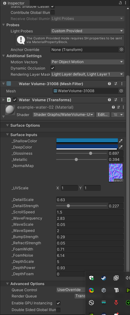
Hey guys need some help I assume its a shader issue but no clue, I downlaoded a shader from asset store all works well but when I enter actual game mode my water is legit grey im doing this project on VR as well, this is how the project looks normally and when in game https://i.imgur.com/zddAsrr.png https://i.imgur.com/QZ6f5nH.png
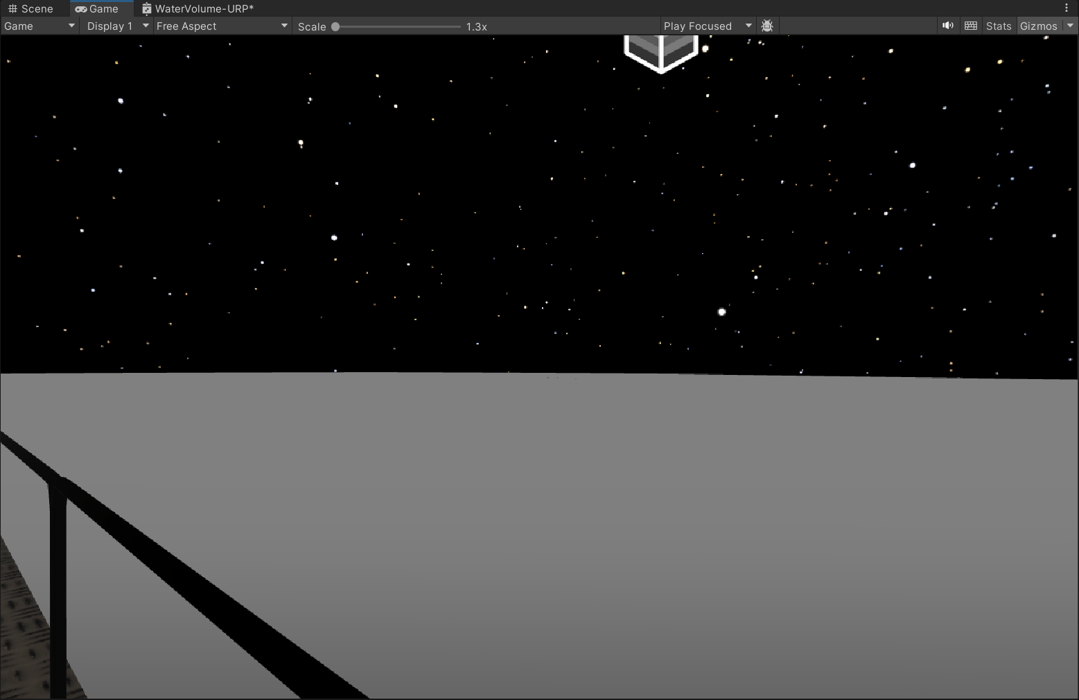
was thinking its lighting but when my scene was still day it didnt help anyway you can only see the blue of the water when u were right next to the railing and even then it was super faded
https://i.imgur.com/tNJ1tT3.png dont know how much info I should provide but really would appreaciate if someone could help me fix this
Hi guys, can anyone help me? I was playing around trying to swap my color in engine and I have the following issue:
When I wanna swap the blue with another color nothing happens, but when I pick white or black it swaps the color for the teeths and the background. Does anyone have an idea why it is not working?


got the color with color picker
anyone know why light is leaking into the room?(there are no gaps)

apparently i somehow fixed it?
someon know how to change the height of my grass randomly, shadergraph urp
rn all grass looks same, in wanted to add variation
Hello! I'm having a strange issue, im following this tutorial making a simple shader and I get to the part where I use an add node to add 2 effects together, however one of the effects isnt applying?

the add node at the end is supposed to have a dark ring around the light green circle but its not applying?
Add just adds colors. If the top color is already bright, adding dark color to it, is not gonna make it darker. 1+0 = 1. Makes sense?
Are you sure they're using and addition node?
yeah, though I think their fresnel color is brighter in theirs
let me try tweaking the colors
pfft, yeah that was it
thank you so much! I was trying to figure this out for a silly amount of time
When blending between effects you'd usually multiply, average or lerp between them.
Addition would only work for specific outcomes and inputs.
I did try multiply and blend, neither of those worked I think
though maybe tweaking the colors might fix it
I didnt try lerp, so ill try that one too!
I mean it depends on the specific use case. In your case the top node seems to have the same color across all pixels, so it would just act as the fresnel color below if you multiply it.
hi! I displace a mesh but the shadows are still cast from the undisplaced mesh.. how do I fix this?
How are you doing the displacement?
I JUST figured it out. the problem was ray traced shadows. appearently that doesn't work well with displaced meshes
ive added https://assetstore.unity.com/packages/vfx/shaders/ultimate-10-shaders-168611
and even after rendering still pink and im not seeing a URP file..

Add depth to your next project with Ultimate 10+ Shaders from The Developer. Find this & more VFX Shaders on the Unity Asset Store.
Hi guys, im trying to achive the "4 star filter" effect, has anyone tried doing that? or maybe someone saw asset doing that effect?
or is it just fancy lens flare?
It does not support URP
Which render pipeline?
uhh, the standard one, not the urp, not the hdrp, i forgot the name
Lens flare component can do it for individual objects
URP or HDRP would have the screen space lens flare that can do streaks
Probably third party assets for it too
Technically it's a type of bloom but instead of blurring in all directions, the blur is done separately in one dimension for each streak
ahh okay ty so is it unusable in project or
Yes
thank you, is there an easy way of removing packages? i feel like they should of had a button to remove packages from project
within package manager
There should be an "uninstall" button for each pacakge
Anything you've imported as .unitypackage on the other hand can't be automatically uninstalled though
thank you Spazi
@grizzled bolt Thanks bro
spazi the masked hero
i seem to be having occuring issues with the urp/lit shader for my spline roads, although its the only shader that has road elements.. any way to fix or that?
Id prefer to use the Lit shader as it is ready to go but when i build the roads just turn white
Dose anyone know of a performant way to "add" shaders during runtime. just as a basic example i have a plane with a lightning bolt shader on it but i need it to shade differently in some areas (for example a black and white shader). Would it be possible to have an area bounded by an object "add" a shader to the parts of the other object (lighting bolt) in the bounded area. With the lighting bolt for example the parts of the bolt that pass through the shaded area would be back and white but the parts that are not in the bounded area would be the normal color. I was thinking of doing something like taking the output for the original shader and modifying in the shader that's adding but I dont know how to make that work on a localized area of the object. I would also like this system to work with shaders other than something that just makes everything black and white. for example using a shader that makes everything partially transparent. It would also be nice to have it work with multiple bounded object with diffrent shaders. For example on object is set to "add" a black and white shader while another is set to "add" a partly transparent shader and where the bounded objects overlap it dose both.
why can i see through the front faces? 2nd image is blender


im not sure if its a shading issue but cant find an appropriate channel to post
unity automatically culls back faces while blender dose not. make sure the faces have the right orientation in blender

So i have an outline shader that works by itself w/ a material, but whenever its applied to another shader as a material using a render objects it just makes the screen black, am i doing smth wrong lol?
Use the frame debugger to see where it goes black. Other than that, you'd need to share more info.
Okay so i have several render objects passes each using less equal depth (no write), first two apply a sort of vhs shader on the object that works perfectly (seperate colors for friendly and enemy), then the other two are supposed to apply an outline shader aswell, but if the first two render object passes are enabled it just constantly shows a black screen, no errors
Did you look at the frame debugger yet?
Let me check

This seems to be using a full screen pass
Share your render feature setup.

In fact your enemy and friendly effects also seems to use full screen effects, so it's not gonna work with render objects.
those both work by itself, its just the outline
Probably because enemy pass is set to be after post processing
And the outline is set to be after rendering.
what should they be?
Hard to say. I don't entirely understand what setup you have. What kind of materials are these.
Another thing is that the blit texture is just 16x16
So it's definitely not the render target that is rendered to previously.


Should i try a different outline shader?
No. You should research how it works and use it correctly.
If you are using it correctly, then the issue is likely with your VHS effect.
See if the outline works correctly without it.
The _BlitTexture here is supposed to contain the color of whatever the draw call above it is rendering to.
oh it only works as a full screen pass, okay thanks
time to use overlay camera fun
Yeah thanks for the help got it working by using fullscreen pass renderer feature
hoorah

I'm a little stuck with something, I'm trying to use triplanar to add a grunge texture to my objects but I want it to ignore anything that's black on a set texture. I'm still new to shaders so any suggestions or pointing in the right direction would be amazing.

Hey so I'm a little confused at this. I have a test graph here. My goal is to define some region as being holographic (red). For some reason this specific setup seems to produce a thin line between the holographic zone and the border. Any tips?


What if you ignore the top lerp and plug it directly into the final lerp? Just so you can get an idea if it's that or the lerp/saturate being the problem
Same issue.


I can imagine it's something with the lerp as those other operations are pretty absolute
I just don't really get why that band is showing up.
I'm using HDRP shader graph, and I want to change the tessellation factor based on x and z position only, but when I tried editing the start fade distance and end fade distance to 0.01, 0.02 the line where it starts getting not tessellated and fades is no different from 6000 and 7000 fade distance, how do I make it not automatically calculate tessellation, and what is the start fade distance and end fade distance even used for?

Hello! Im using vegetation spawner to spawn grass and the grass is white, im using a 2d texture and HDRP. Can anybody help?

It's not polite to crosspost
If you're not purposefully using custom shaders it's not a shader channel topic
If you are, you'd have to give the relevant details about the custom shader
Either way, you have to use a shader that supports what you're trying to do
Best to delete the less relevant one, but at this point we don't know whether your main goal is to make shaders or just to get the tool working
It is more about shaders
So, what kind of shader do you have and what is it meant to do
Does the vegetation tool you're using require a particular type of shader to function?
i used a different tool and i got the same results
Doesn't help us help you
why are these white and gray spots apear?


They look like warped specular reflections
I would guess your mesh's vertex normals are inverted near those spots
Its just terrain tools
How can I remove em
If it's Unity's Terrain rather than a custom mesh, inverted normals would not be possible
Unless you're also creating a custom shader for it, use the #⛰️┃terrain-3d channel
I did make a terrain layer for it
Let's say I have a material in Unity that controls the appearance of a card. Half of the material properties control elements of the cards position and some masks. The other half of the properties control a holographic effect. There are many different types of cards (so different positions and masks) and many different holo effects. How should I represent all of this in data?
hello! I was having issues with Lit shader, found a reconstructed Lit Shader and i am trying to make my road non seethrough like i should not be able to see the road below when im on the road above. any fix is appreciated.


Hi guys total noob here, I am trying to make an outline shader material (URP) so I can assign it to meshes the player interacts with:
I followed this tutorial, its okayish but is pretty bad around straight edges as you can see from the pic
Could anyone give any insight on how to make it better


Wait a second. If I am in URP, is it better to use MaterialPropertyBlocks, or just create new material instances?
"Surface Type: Transparent"
You can change it to opaque
Or enable material override so you can change that setting per material
Material instances as those work with SRP batching
So how do you disable preserve specular in shadergraph?
So just... create a new material, and used the sharedMaterial as an argument?
And then make sure to Destroy the created material on Object destruction?
Should be down the list in graph settings, if transparent type and alpha blend mode

...not sure how I missed that. what I get for shader0ing at 4 am 😄
sharedMaterial is not necessary since that's the original material asset
Renderer.material can be modified to create the instance, but you do have to destroy instances later
https://docs.unity3d.com/6000.0/Documentation/ScriptReference/Renderer-material.html
Example included
m_Material = GetComponent<Renderer>().material;Really not a fan of this. Looks like I'm accessing a simple property when in reality it's creating a whole new material instance and assigning it.
Oh well
Probably the same as instantiating from the sharedMaterial, which you might have to do anyway if you need more than one instance at the start for different purposes
What's the procedure for a mesh with multiple materials?
As far as I know it's exactly the same material list you see in the inspector
Alright so calling it just once does the same thing as material but for all of them.

Yes
You can copy the array without setting it, or assign your own materials to it without copying it first
Not that many situations where you'd want to modify the sharedMaterials so I understand why they replaced with the shorthand for creating instances
Or if you do need to modify the assets themselves for all users, it seems very unintuitive to me that you'd do it from an individual mesh renderer
I have tried that nothing changed 😦
Did you save the graph too?
Double checking now I believe so I always build to test after but does it not save before building
It should ask you
But you must hit the save button in the shader graph window, and the result should show up in scene and game views
No building needed
Appreciate you spazi trying it shortly
to be honest i just opened the scene up and its now showing okay
so it most likely was saving issue, they should make it so it auto ask that save or what not or maybe it just needed that? idk.
shows great now!

appreciate your help @grizzled bolt thank you again
I feel ilke this is probably a shader question... when doing a ton, like literally 1000 lights at once in a UGC game like a city builder, what is the best way to shade emissive decals so they don't wipe out all the texture detail underneath
At least that's what it looks like games like cities skylines1 and Planet coaster 1 are doing


I don't entirely understand your question. Or if it's even a question at all...
I also don't see many decals in the screenshots.
do you think its just deferred rendering then?
First, you'll need to rephrase your question/message such that it makes sense. Did you even try reading it after sending? Among other things, I've no clue what you mean by "wipe out all the texture detail underneath".
Assuming I understand you correctly, you're asking how the "lights" in the screenshots are rendered.
If so, I'd assume that it is either deferred rendering + some unlit materials, or baked lights.
the screenshots are from the game directly as an example, wipe out/wash out texture detail is a relatively generic normal term. Basically im asking is there a blending mode like multiply that preserves more of the texture detail when the decal is applied over top as apposed to normal blending.
At distance, the game apperas to be using some kind of emissive decals but I was able to dig up an article since my original post that says they did also use deferred rendering. I can't share screenshots of what I'm working on.
it doesn't take a tremendous leap of logic to understand my question if you have ever worked with decals as a light source though so I don't understand how you are confused.
The way decal is rendered/blended is dictated by the material. If it's using a transparent shader, you often can define how it's blended(for example a custom shader graph shader has that option).
I don't think that the game is using "emissive decals". light via emisssion is a lot more expensive than some lights in deferred rendering.
Literally just try reading this sentence:
At least that's what it looks like games like cities skylines1 and Planet coaster 1 are doing
No punctuation, no question mark. It seems like several sentences are mashed up together and it's not clear where assumptions end and the actual question starts..?
Ok, I guess The first message kinda sounds like a question, although with terrible punctuation. But then the message with the screenshots implies something that is not explained anywhere.
Kinda like you forgot a sentence in between.
ah so that's why there are 2 commas identifying the interrupter context, though granted the subject is inferred in the context which is a syle error. Not a grammar error.
but this is discord, not english class.
Anyways, it's really confusing and feels like there's lack of context.
It's fine if youre english is not perfect, but if people don't understand you, it's hard to provide any help.
i think the question is how to run that many lights in a not-insane way (emissive decals?)
with examples of games that achieve the desired effect being Cities: Skylines and Planet Coaster
can i actually utilize height maps from substance painter in unity? (Built in pipeline)
height can be used for displacement in HDRP, no idea if built in has any thing provided for this. Stick with normal maps.
nothing stopping you from doing some manual displacement in a shader using the height map
yeah... how? lol
i mean, in shader graph its possible using some vertex position plugin?
sample height map tex, use to move vert along its normal or some other dir, win
plugin?

so sample height map -> mult with a float for scale/strength
the rest i dont quite follow
a height map is 1d so to "displace" the vertex you need to know what direction to move it so you can use the vertex normal multiplied with the height value
object space probably
yes leave as the default
default was world space
huh... thats weird.
it appears to be a vector3 output

wont allow it in
I dont follow
the input to the vertex position node is yellow (vector3?), and my output appears to be yellow (Vector3)?

it wont plug into it
oh hol up
no...
it dont like the sample texture node


means you have no camera

too lazy to rewrite sorry i jus realised that i send the actual pic in the wrong chat\
yeah i added one and it worked thx
!collab
:loudspeaker: Collaborating and Job Posting
We do not accept job or collab posts on Discord.
Please, use Discussions to promote yourself as job-seeking, advertise commercial job offers, or look for non-commercial projects to participate in:
• Collaboration & Jobs
my bad
So… because my models are super zoomed out, I need to make the normal map pretty huge to see things like panel lines in the texture from the distance the camera is at
For some scenes I’d want a closer view of the ship though, and it looks silly at close range. can’t I do some LOD and switch normal maps based on camera distance?
yes, LoD for mesh, and mip map for normal maps (textures)
In the 2d light system, since all lighting is just rendered to a texture that is sampled, how does unity do the normalmap calculations? Is it possible to get out any light directionality in my own shader graph for custom calculations?
fixed, I found that I needed to edit the tessellation in the material rather than the shader graph settings
Hey everyone, I’m running into an issue with an asset pack I recently purchased.
I imported everything correctly from the POLYGON Nature – Low Poly 3D Art pack by Synty, but when I place trees in my scene (specifically the non-LOD versions), the trunks show up bright red and the leaves and grass look strange—nothing like the examples shown in the pack.
I also tried using the LOD versions of the trees, but those show up completely gray, like the textures aren’t applying at all. I suspect both issues might be shader-related, but I’m not sure how to fix them.
I'm still very new to Unity and game development, so I’m struggling to understand what’s going wrong or how to resolve it.
If anyone is willing to hop into a voice call and help explain this stuff a bit, I’d really appreciate it. I’ve tried watching videos, but they haven’t helped me grasp what’s going wrong or how to fix it.
What template did you select when you created your project?
Universal 3d Project
I think the default materials are for built in render pipeline, and it comes with a separate package for URP support
Yeah I noticed that if I am correct, But how would I add the URP then
Double click the package
I cant find the URP
I need some help fixing a visual bug in my shader, the shader is supposed to distort objects behind it but for some reason, some objects get reflected in it

I assume this is due to the fact that scene color is getting specifically what's rendered in my main camera
this being the relevant part of the shader for that

and this is the shader in action
for the sake of context this is the full shader

the texture that gets sampled is what makes the waves below the player but that part is relatively irrelevant, how do I get the shader to stop reflecting objects on top of it?
Make sure the drawcall is right after rendering water and not anything else.
If it's non opaque object, this might be difficult. In this case you'll need some kind of depth or stencil test.
I was hoping not to add another renderer feature on top of that growing list but it seems I may have to
that said, would it even be worth fixing?
I feel like with flatter objects it'd be much easier to get away with
Not sure what you mean by that.
It's up to you. If this kind of effect is acceptable to you, why not.
so instead of a tall pillar standing up I could have an island of sorts
I feel like that'd make the problem a lot less noticeable
Try it and see for yourself
I'll just leave it, I don't think it's enough of an eye sore to add yet another renderer feature
got enough of those frankly

I have a script here whose job is to set the properties of a material. Aka a lot of the methods look like this.
    public void SetStone(Texture2D tex)
    {
        cardPlateMat.SetTexture("_StoneTex", tex);
    }

    public void SetCenterPoint(Vector2 center)
    {
        cardPlateMat.SetVector("_CenterPoint", center);
    }

    public void SetNameplateCutoff(Vector2 cutoff)
    {
        cardPlateMat.SetVector("_NameplateCutoff", cutoff);
    }
Should I expose the string values as fields to be able to tweak them in the editor?
Sure. Why not?
...that's fair I guess
If you only have a limited set of properties, you could define them in a scriptable object or a singleton/static class to avoid typing the same string everywhere and potentially making a human mistake.
if you are changing so many properties at the same time i might make sense just to swap materials
any clue why this is happening
I've seen people create shaders that physically raise the mesh from the ground, considering I'm working with a quad so not many vertices to raise, how would I go about doing that?
one idea that just came to me was to create a plane with the same amount of vertices as pixels in my shader and use tiling to fix the uv scale being wrong
but considering my resolution for this is 1024x1024, I would like to find a better solution
have you tried setting the alpha clipping property at runtime?
What's the equivalent to Mathf.Repeat in shadergraph?
Looping a value between 0 and 24
or 0-1
Depends on how i implement the code later
sample gradient, and hook it to a remap node maybe
then hook time up to whichever direction that gradient should go in
lemme see if I can find something better
I found something better

and depending on which part of that split node you hook it up to, the stripes go in different directions
unless I'm misunderstanding what you want that is
my goal with doing this is to raise parts of the mesh depending on the (currently fake) height values I have
specifically on the ground
also if you wanted either one value or the other, instead of a wave I believe something like this would work

this one I'm not so sure of, I'm not entirely solid on how the normalize node works here
still all depends on what you're trying to achieve with that value
i might be overthinking it honestly
Wanted to make a skybox
and change the color from the time of day
wouldn't you want to control that transition in a script?
not particularly
Okay then i guess syncing time every second or maybe even less frequently should be fine
you could probably do it with a time of day float and let the shader handle itself based on that
if you transition smoothly every time you update that float you could probably get away with updating it even less frequently
Wait why did i even want to loop the float
I can do that in C#
Well that makes everything easier
yeah you just send a float with the current time of day to the shader and let it do it's thing based on that
then update your time of day in script
I shoulda asked what you were tryina achieve straight off the bat my bad
kinda xy'd myself by mistake
I've never really used shaders in the context of unity
how do I change vertex position in a shader that isn't a shader graph
anyone got any suggestions on how to blend the lighting info and textures for my custom lighting shader better?


the lighting always comes out very gross, ive tried a few things and ive definitely narrowed it down to where I combine the light colour and base textures where I multiply them, but I cant figure out a different method to get better results
at low intensity its fine but at high intensity it shifts green significantly


i sorted it 💪 thank you for rubber duckying

Yes
No avail
hello, I am learning compute shaders rn, following a tutorial, and am confused on a few small things. Would appreciate if someone could point out where im getting something wrong here or clear up the questions i ask in the comments!


How do you control a ShaderGraph enum field from C#?
Share !code properly next time.
Posting code
📃 Large Code Blocks
Use links to services like:
https://paste.mod.gg/, https://hastebin.skyra.pw/, https://paste.ofcode.org/, https://paste.myst.rs/, https://scriptbin.xyz/
📃 Inline Code
Surround code with three backquotes. Not quotation marks.
To format as C#, add cs to the first line:
```cs
// Your code here
```
Add a comment with a line number if there is an error message.
Compute shaders are not bound to pixels, like a pixel shader. You can run any arbitrary amount of threads. The dispatch Id is unique for each running thread. You have a total of (dispatch groups * threads in group) of threads. The ids represent the id of a thread within the total threads.
In your shader you're using the IDs to write data to a texture, so you use the thread Id to specify what pixel of the texture to write to.

Pink usually means NaN or infinity. Invalid value basically. Power can produce these if the input is negative or the result is too high and it's causing an overflow.
but i lerped
If t of lerp is negative it can go negative I think
Try saturating the t before lerp
Or saturating the lerp output
The t parameter of lerp needs to be in 0-1 range for it to produce values in the a-b range
At which point your lerp is meaningless though
worked, thanks so much. i didn't understand lerp
Honestly, I'm not sure what you're trying to do with it.
the eye's pupil
do u know how can i replace the power node while keep controlling the blur ring around the pupil, i heard that it is expensive ?

It is. Maybe some kind of gradient or curve?
they are not modifiable in runtime
Why not?
the gradient doesn't expose on material properties when i add it, and i dont see the curve node, where can i find it ?
How are you adding it?
What node are you using?
I was not talking about specific nodes. Just concepts.
i add the 'gradient' in SG properties
If it's a property then it should be exposed.
i checked on the internet many times and people say it cannot be exposed

Ah I see. In this case, I'd use a texture containing the gradient.
Something like 32x1 texture. Then just sample the color like with lerp.
thanks, i will consider it
is there a way for me to pass in info to the compute shader or update a struct array for the IDs to use? for example, if i had a 2d array of structs, each representing a pixel with its various data (ie color and ingame info) that would have its contents updated/changed, is there a way for me to update a matching array in the compute shader script/ or pass in an induvial struct instance for each ID of the texture?
Yes, you can bind a buffer with your data to the compute shader.
Check the documentation on compute shaders and compute buffers.
alright, ty
Is there a way to map square into circles?
What do you mean by "map square into circles"?

Polar coordinate UV?
Ts channel is my brother
If im using a compute/fragment shader to simulate the behavior of falling sand, would i not be able to use the traditional algorithm that relies on looping through the 2d array in reverse due to the fact that fundamentally all pixels would be updated in the same time and so could not iterated through like that? Am i misunderstanding how they work

What's this image meant to tell us precisely
The polar coordinate UV doesn't conform the texture to circle

I'm trying to map it to circle like this
If the algorithm cannot be run in parallel, then it cannot be used efficiently with shaders.
A GPU core is just a slower, less capable compute unit compared to a modern CPU core. The difference is while you may have 8-16 CPU cores in a modern desktop CPU, a modern GPU can have thousands. That's what make GPUs faster at certain tasks.
Yeah thats what i am imagining. Could i say split into larger grid cells that each run in relative parallel (say 2x2 cells, each iterating a total of 4 times)?
Or would that still not be an effective use
Talking about the circle on the outside or the circle on the inside?
In what way is this problem not possible in parallel? Why is it important that the algorithm is iterated in reverse?
Because two ‘pixels’ may both attempt to occupy the same space, such as if it was a 3 wide, 10 tall grid, with two pixels in each bottom corner already, if you dropped three sand at the same height, they would all try to be in the bottom middle gridspace at the same time when they reach it
If you iterate in (actually bottom left to top right, not reverse), you can use the last pixels updated info as to not attempt to occupy the same space
So the order is mainly dictated by the direction of gravity?
Have you looked at examples of compute shader pixel sand simulations? I expect the techniques are different from doing it on the CPU
I saw one, which relied on having every possible 2x2 grid formation possible for each type of pixel (i think?) and a large amount of if-statements for each algorithm to decide what will be the next state. From what ive seen this works well but atleast to me seems unreliable when working with a large amount of material types and factors such as density & weight
The one on the inside
Its color picker, but mapped into a circle
I'd try to look for more, in case the one was made in a unique way
Alright, ill do some more research 👍
This one is easy, but mapping it into a circle is hard

Oh and best to understand compute shaders as well as possible to begin with
Very difficult to use if there's any confusion about the terminology or how it works
Sand simulation is a pretty advanced effect to make in it
It'd be more descriptive to say the texture/uv is bulged, and then overlayed by a circle

Polar coordinates on the other hand do map textures to a circle, like the outer ring there

But without mapping it properly it will lose some color range.
I managed to get the full color wheel hue with shaders

will material recalculated each update when i dont change it's properties at runtime ?
Then the problem you're trying to solve is more involved than to just make it a bit more spherical, if you need to also ensure specific proportions or ranges
You can view the code of the Spherize node in the package docs to modify the math as you need
https://docs.unity3d.com/Packages/com.unity.shadergraph@17.2/manual/Spherize-Node.html
disregard the message below. fixed using a canvas shader graph. sadge
can someone end my suffering please for the love of god
i have a simple problem that i just cant figure out
i have a 2 camera system in my game:
the WorldCamera outputs to a render texture called WorldView
the MainCamera looks at a canvas which is rendered behind all UI elements called WorldCameraView.
WorldCameraView has a Raw Image component that takes in the WorldView render texture, and a material generated by a shader graph called WorldViewShader. WorldViewShader has an input property called MainTex which references _MainTex. when removing the material on the Raw Image component by setting it to none, i can see the world camera view just fine. adding the material generated by the shader suddenly causes my whole screen to look like this:

I have some sprites that I want to be reactive to 3D light.
I put together a simple transparent Lit Graph (not Sprite Lit) to do so, and am trying to get the SpriteRenderer controls to work with this shader.
How do I feed in the color? I keep reading that this is pushed in through Vertex Color, but I am not seeing anything happen.

Afaik, sprite rendered just uses a color property with a specific name. Check the sprite shader to see the specific property name.

Looking from the grid, its still missing color range with spherize, I guess I will have to figure out how to deform UV into circles correctly like the other figure.

This would've been perfect but its far beyond my level to implement.
John D. Cook | Applied Mathematics Consulting
Conformal map between square and circle, and its application to the Peirce projection map
Am I absolutely dumb or this should be making it transparent??? (3rd image is not transparent, it's just what happens having it on additive mode)


Looks transparent to me. I can see the grass pattern below.
Cause it's on additive, not cause it's transparent
Additive is a mode of transparency
Besides, if it doesn't work in other modes, then you should be showing that instead.😅
It just works on additive, but not changing the texture alpha, the material alpha or the material color alpha does anything
But I cannot really control the transparency with that, I would need to modify the color tone, rather than the oppacity
Can you set it to 0 with a constant in the shader and take a screenshot of what it looks like?
I kinda figured it out. For some reason alpha channel does absolutely nothing when applying ig to a sprite while being a normal lit material
So I have to change to sprite, but shouldn't that work anyways? I mean, it's pretty much a texture
Sprite renderers implement some features differently to mesh renderers and thus require sprite shaders. Perhaps that's it🤷♂️
Other than that you'll need to provide more details on your setup.(Like where and how you set the alpha).
I think sprites need pre multiplied alpha on the colour output 🤔
If I wanr to apply a pixel shader to the game, but I dont want all the objects to have it. Only objects on the interactable layer