#archived-shaders
1 messages · Page 83 of 1
Ok, I found how to trigger the issue : is happens when the bool variable is declared outside of the fragment function in my case.
Before I was just declaring directly in the function
yea that fixed it, thanks!
I'm unsure about why it acts like this though.
Is there a simple way to clip pixels that are a certain color (red)?

Does anyone have suggestions on how to filter out a certain range of brightnesses? I'm trying to make this water have foam on it, but I feel like the shape of the voronoi texture is kind of detracting from it. I want to try filtering out all the bright whites or something (like set the alpha of the bright white to zero). I tried using the clamp node and the min/max node but it doesn't seem to work like i want it to

Or if I wanted to try filtering out all the more subtle greys and just leaving the bright whites, something like that
smoothstep or step node (or function)
note that if using step, usually you'll need to 'invert' the color
ill give it a shot thx
In built in render pipeline spotlight goes through walls. In urp there's no problem. Any suggestions?
anyone knows whats upt with this? this is really stagnating my gamedev right now
Shadows must be enabled in the light and meshes so the light can be occluded
#archived-lighting
i use legacy diffuse shaders and that doesnt help at all. i have shadows enabled.
how can I get a smooth fade between these 2 materials?

- Have a single material sampling both textures en blending in ssome way (normal based, vertex color ....)
- Hide the transition with decals
is there a way to make "flat" shaders w. shadergraphs where the entire 3d model is rendered with no depth and is instead a flat color?
Unlit graph?

Yeah that would just be unlit - "depth" is still technically rendered or it probably wouldn't sort with other objects correctly
Was also wondering how a different shader was applied based on a line on the screen

Screenspace shaders maybe?
Could involve Stencils, or possibly just ZTest Greater if the red part is infront
Red part is behind
the vertical line moves and changes some parts of the 3d model moving to have a white shader instead
Here's the vid represenation: https://www.youtube.com/watch?v=VqJnmphV9R8

Damn so cool and stylish
its a bit late but who cares ?
CPU - i7 3770
VGA - GTX 1050TI
RAM - 8GB DDR3
Don't forget to visit my blog https://www.dtechnology.dev/
well... I don't know exactly what you mean. One material, okay, but where do I put them in? I can't find something like this. I don't really know much about it.
You need a custom shader applied to a single material over the whole mesh
I want to make an overlay on top of a texture with shader graph but I can't figure out how to do it because is I use add, it doesn't work because mjy overlay is black and same for multiply, can someone help me with this please?
Use the "Lerp" node
I'll try it but how does it work?
Where can I enable tweaking the variable values of the shader graph in the scene?

Tweak them on the materials. ? I don't get the question, what do you want to do ?
Yes

Currently in my materials the option to change those base value numbers are grayed out
the "strength" and "size" ? I don't see them grayed ou in the screenshot ?
sorry this was a screenshot from a tutorial I was following, give me a second

Are you inspecting the material that is a sub-asset of the shadergraph ?
This is the "default material" bound to the graph, and is not editable.
You need to either create a new material using this shader, or a material variant of the default material
Ahh gotcha. Yes I was inspecting it as a sub-asset of the shadergraph.
Thank you!
can't make it work
Show the graph and how you're using it.

The connections seems fine, and when you change the "Strength" value, the overlay doesn't show up ?
nop
I tried 0, 0.25, 0.5, 0.75, 1
none worked
is it because my overlay is black?
so it does like if it was not here?
No. If you set the B input to red, and T to 1, doesn't the lerp node display a red preview ?

Yep, so it works
okay, I don't know anything about shaders. I think I need to learn much more about that to be successfull.
Could it be that the "Overlay" texture is set to the same brick as default in shadergraph ?
here's with a strengh of 1

Ok that's what I expected
so, what do I do now..
You need to take into account the alpha of your overlay in the lerp.
Multiply "strength" with the overlay alpha, and input it in T
thanks ❤️ ❤️ ❤️

How do I use a dissolve shader to transition from one texture to the next? Is this possible?
What I'm trying to do is I have a semi-transparent sceneColor dependent green texture and an opaque texture, and I'd like to use a dissolving shader to transition in between them
Currently I've tried using multiple materials on the same renderer but that did not turn out well
you can sample gradient noise and branch between the textures depending on whether the noise is below/above a threshold value
Hey, i have a simple tile in 3D like the screenshot shows. I would like to have edges shown like selected effeect, using shader graphs. All of the tutorials are showing just the edge, but not the inner ones. I would like to have like the 2nd screenshot. Idk if it's possible


It works! Thank you, now I now something about shaders.But it's a bit tricky to add normal map and height map for me.
a free asset called "ultimate 10 plus shaders" has this shader
I'm running into an issue where my shader looks good when in scene mode but does not work once its game mode. I'm pretty new to shaders, so I'm not even sure how to debug them.


I'm aiming for an intersection shader to show the in-bounds area.
Oh boy, I just had to toggle post processing on the Camera object. Nevermind 😭
I was hoping to use shaders to create a linear "progress bar" effect. The method I'm using doesn't do what I have in mind (22 second video demonstrates what I mean). Is it a result of the gradient I'm using as the texture, or is it something else entirely?
in my shader I have properties:
Properties
{
    _Color ("Color", Color) = (1,1,1,1)
    _MainTex ("Texture", 2D) = "white" {}
    _Cutoff ("Cutoff", Range(0,1)) = 0.5
}
and in the subshader, I only changed frag to look like so:
fixed4 frag (v2f i) : SV_Target
{
    // sample the texture
    fixed4 col = tex2D(_MainTex, i.uv);
    clip(col.r - _Cutoff);
    // apply fog
    UNITY_APPLY_FOG(i.fogCoord, col);
    return _Color;
}
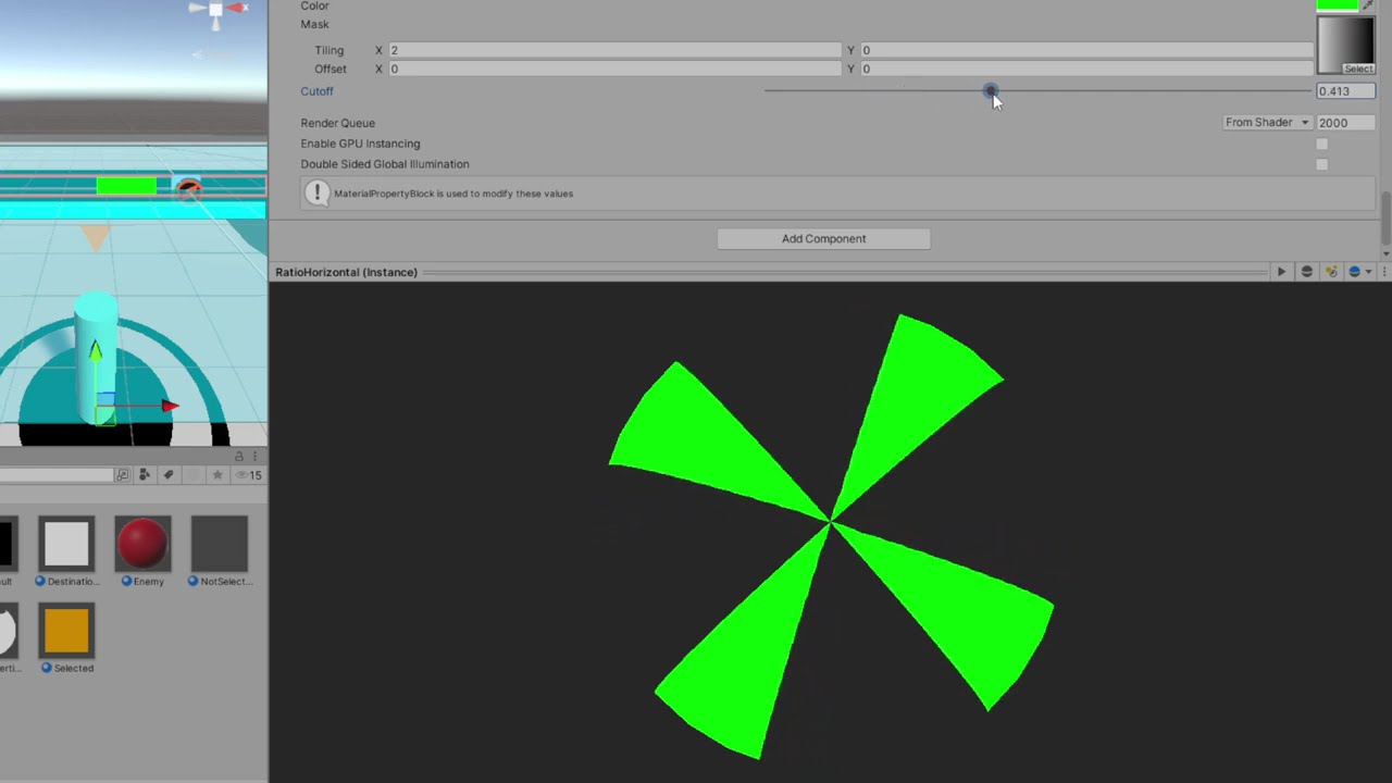
Make sure the texture has sRGB disabled, to indicate to Unity that it should be treated as linear non-color data.
That was exactly it thank you 🥹
Thank you!
Hi there, is there a way to fade my skybox detail from 1 near the sun, to 0 completely away from the sun? I am using a modified and custom version of the standard procedural skybox
half skyboxTime = _WorldSpaceLightPos0.y % 360; I am using this to calculate when it should appear, but I was thinking more like the diagram shown:
How I am applying it in my script
col += tex2D(_DayDetail, calcSphereUV(IN, float2(0, 0), 0.02)) * saturate((skyboxTime + 0.3) * saturate(_AtmosphereThickness));

(Orange ball is the sun position in the sky)
_WorldSpaceLightPos0 will be a normalized vector, so y will only range from -1 to 1. You can use dot to calculate how similar the sun direction is to the UV and generate a gradient like that.
The mesh that the skybox is drawn on already has 3D uvs you can access. It's equivalent to the view direction.
Thank you, I got it work how I wanted!
Although
Is there a way to do the same effect, but only on the vertical axis?
Wait
I'm stupid...
Nevermind, but thank you
hello, i am using polybrush and a slightly modified version of one of the HDRP sample shaders, im using the paint textures on mesh setting, but it is currently painting only individual faces on my mesh, whereas i was hoping for it to be a circular brush. What would the best way of going about this be?


this is the entire shader

this is probably a dumb question but how do i fix this? i didnt make the shader and i dont know shadergraph but this is the only good water shader i have :(
What's the code?
Oh xD im gonna look for it thx
heya, for some reason i get parts of the mesh rendered even though theyre behind alpha 1 faces, and it makes it look really weird, anyone got any idea why?
im guessing it has somethng to do with depth testing
this is just a simple test i made, and its all wonky

Transparent objects don't typically write to the depth buffer so they can blend. Ztesting still occurs but since those faces don't write depth it's hard to sort them. They'll just appear in whatever triangle order the mesh uses.
I've got some more info and possible workarounds here - https://www.cyanilux.com/faq/#transparent-sorting
okie thx alot!
hi guys! sorry if this is not the right place to ask this but... I was wondering...
Is there a way of making a TilemapRenderer to act as a Sprite Mask?
I came across a thread in the forums from 2023, it said that it was not supported, but I was wondering if maybe, as of 2024, it is now achievable? (or maybe there is a way of doing this by using shader wizardry™)
as a side note, I could create a spriteshape that resembles my tilemap and then use it as a mask, but, in this occasion, I want the sprite to only be renderer over the white parts of the tilemap 
Hello! I am creating a shader that gives each object on the screen a separate color based on that object's transform.position coordinates to test using the feature, but it seems whatever I do, my objects all have the same color. There must be something I'm fundamentally misunderstanding about the object node, since I can't get differing colors from it:

Position values may be outside the 0-1 range that would display visually as different colours
I want to sample a normal map on a custom lit shader graph.
This is used to render a plane mesh along the XY plane. The UVs are the XY world space position hooked to a tiling and offset node.
This works fine when sampling a regular texture, but when the same UVs are passed to a Normal From Texture node, I get erroneous results. Results are the screenshot attached. It should be a hex grid instead.
Any idea what step I am missing?
Edit: What is seen in the screenshot is the normals sampled hooked directly into the color output

one other thing to mention is this is a fullscreen material shader if that matters. I thought that if the values were too large to visually display, then they would be white, but this example makes the screen black.
If using a normal map, you want to use the Sample Texture 2D node with the mode/type dropdown set to Normal.
Normal From Texture is used to convert a greyscale heightmap
Fullscreen shaders won't be able to use the Object node. That only makes sense for materials applied to objects.
Is there any way for me to get the transform position of the object connected to a vertex in fullscreen?
You may want to look into custom renderer feature to render out a custom pass, assuming URP
Thank you sir!
yep I'm using urp and a custom render feature here
Then should be able to use DrawRenderers / cmd.DrawRendererList to redraw objects into a custom RTHandle. With overrideMaterial set to shader using the Object node.
Then pass that RTHandle to global texture property and sample in your fullscreen shader/pass.
Alright thanks, I will look into that
I don't do much 2D, but sprite masks use Stencil operations behind the scenes, so might be possible to replicate with a custom shader
thank you very much! this is a really good starting point
so i've been trying to take my old surface shader and convert it over to URP via shadergraph. i got almost everything the way i want, but i got no idea how to get shadergraph to cast shadows on the 2d sprite without going through the inspector's Debug and manually turning it on.
i figured enabling the "cast shadows" on the surface options would take care of it. but it doesn't work, yet changing it in the debug does.
figured it out soon as i started complaining 🙃
This was really helpful! Here is an update so u can see you really lead me on the right track:
The first image shows a different color for each 3d object representing its screen space, and the 2nd compares the uv color of the fullscreen shader to that color to check they are where they claim. Thanks so much


hey, looking for a transparent shader that only lets one face rendered so that transparent faces dont stack
Is there a good way to flatten an object's normals, such that light reflects off of it as if it were "flatter" on the screen?
Preferably without using a Post-Process effect.
Nevermind, I figured it out.
I programmed this shader. It will take the vertex colors for the smooth fade of 2 materials. (Pic1)
After that I programmed normal/height/Occlusion etc. in it.
But now my textures always appear just white.
EDIT: I have to take out the Emission but the top doesn't get any light.


Hi! I've got a small problem. I have like 300 water tiles and I haven't had a problem with them until now to be totally honest. Something seemed to change and now I can very easily see the edges of the water tiles because of the light reflections just being completely cut off when they reach the edge of a water tile instead of seeming like the reflections is being shared between the tiles.
I show the ShaderGraph that I use, sadly it's a ShaderGraph/Material I got off of the Unity Asset Store. I've been able to decipher parts of what is happening in it, but I'm not quite sure what could fix my issue. I feel it's something to do with the Screen Position being plugged into the light reflection/Planar Reflection. But I honestly have no idea, and I really hope someone can help
Did you Chance the tiling/offset on the wave? It seems like your tilling or offset isn't correctly. Run the project and try to change the values. If you stop the game, it will be set to default.
I don't remember changing anything like that.
I don't even see anything to change it, unless I'm just stupid and don't understand what you're talking about XD
Wait do you mean my WaveController script and not the shader?
Yes.
I have an offset and speed for two waves. It controls all the meshes and calculates the heights based on the two waves.
I made the speed and the offset of both the waves equal eachother but you could still see the sharp edges of the tiles
I can See you have some variables like Offset 1, Speed 1 etc.
Run the game and change the values. So you can see what exactly changes.
The Amplitude 1 is 0.43f in unity but is 0.4f in your Script. This can be the fault.
The offset just controls the position of the waves based on its speed
And the other values? Change them a bit, so you can See what happens.
Oh SHT, I'm stupid!
Omg thank you! XD
It's the Noise strength/noise scale that I added to add a tiny bit of randomness.
Welp. I gotta find a way to make the noise strength/noise not cause this problem. Fun times
I'm so thankful you actually got me to mess around with it, because I thought I knew what exactly it did, because I spent weeks on it. But nope, XD the newest feature to it is what caused the issue. lol
Thats mostly the first Thing I am doing everytime I messed up some graphics 😄
Jeez, and here I thought it was something Unity did because I just haven't noticed that issue until I downloaded the newest editor verision XD
Anddd I've already got a fix to smooth out the noise.
Thank you! ❤️
It does
for it you also need Screen Position: Default for the UV input, and the Type should be Default, not Normal
You also need to have a 2D renderer active so that 2D lights can be calculated
Not nearly
2D lights are a specific system that requires URP with the 2D renderer to be active
Using the 2D renderer locks you out of any 3D lighting in turn, though
Depends are you using URP to begin with
#archived-urp has pinned instructions for the setup process
It should, and it should also set the default material of sprite renderers to Sprite Lit which is required for lighting
You also must be using 2D light components, not the default 3D ones
You should be seeing the lights interact with your sprites before getting into custom shaders
Since your 2D lighting works, start by trying to output the sampled light texture directly, with the changes I mentioned
Custom Lit sprite graph only, afaik
Are you testing in scene or just looking at the SG preview
The issue may have been that you've been expecting the node preview to show the light texture accurately
I'm surprised it shows anything there
If the sprite looks "transparent" with the light texture plugged to fragment color, that may be working perfectly
Since all your sprites seem to be the same white color, each one of them can only get its appearance from lights
You could still test by outputting a one minus of the light texture
Then it would show the inverted color and you know for sure it works
One minus node, not multiply
You should make sure the sprite is not behind the other sprites
In position or sorting order
That can make it seem transparent also
One minus doesn't seem to work with the 2D light texture as I'd hoped
But the light texture alone should still appear to show the lighting as if lighting a white surface
For that reason you'd usually want to have more textured sprites near it to see the difference
The light values are not in 0 to 1 range, that's why one minus didn't work for inverting it
I programmed this shader. It will take the vertex colors for the smooth fade of 2 materials. (Pic1)
After that I programmed normal/height/Occlusion etc. in it.
But now my textures always appear just white.
EDIT: I have to take out the Emission but the top doesn't get any light.


Is there a place to systematically learh what each component in the shader graph, roughly does?
So to speak*
have you checked the manual?
https://docs.unity3d.com/Packages/com.unity.shadergraph@14.0/manual/Node-Library.html
I have not thank you

aboutta 
In addition to docs there are some videos that go through all the nodes (at the time of recording) and some common use cases which can give another useful perspective
Hey guys, programmer here, shaders have always kinda escaped me, but I'm trying. Would this be the best place to ask questions about shaders?
Well ... here
Essentially I'm trying to make a reveal shader, and the axis it's revealed on would be based on the enum (x,y,z). Maybe this isnt the best way to do it - if not please let me know, but I'm a bit stuck here. Previously whe nit was just Y/Z it was easy - just use a branch. True = X, false = Y => pass that information, but the flow is kind of confusing to me

Left side: beginning of set up - right side, y/z previous set up (now changed to x/y/z)
it flows/works on the X/Y, just confused and could use a pointer on how to set this up, and gpt hasn't been helpful

GPT suggested this kind of thing

and if I do get it right, I'm still not entirely sure how to pass this positional logic t othe next section (where it was easy with a branch previously)
You don't need Branch nodes, the keyword node kinda acts like the branch itself. You'd input the X Y and Z groups into it's input ports
Yes thats how it should flow

Sure, though Z has a different space - I assume that isn't intentional.
If so, could also use the outputs from one Position & Split, no need for multiple
Changing the keyword entries to XYZ instead of ABC would also make sense
Haha yeah - I realized that immediately on test, fixed that as well. Thank you
And yeah, I had em as X/Y/Z but accidentally ctrl + z'd while outside of shadergraph, and it undid that history change
but thats sorted as well. Nice catch
all axis are working as intended, thank you!
Also, if anyone has any suggestions for courses on shadergraph, I'd definitely be open to that
Problem here
Why cant I edit the material properties (I want to make the material unlit basicaly (so like the colors are not affected by the lights))

I figured it out
Was it readonly/owned by an imported object?
I imported a file from blender and the material it came with was uneditable so I made a new one
Has anyone watched the cartoon 'Chowder'? How would you achieve in 3D how the characters move but the texture stays the same.
Ah yeah, in that case I usually just ctrl d (duplicate) that material
yeah thats a better solution than to make and settup new one :D. thanks
is it possible to add depth to a plane through a shader? without adding extra geometry
or maybe the illussion of depth?
Can I call HLSLPROGRAM code from ShaderLab? If so, how do I do it? If not, what's the point of HLSLPROGRAM?
Is there a reason my particles, if set to lit in shader graph, have a light grey background? I'm using the default particle as a mask, which works in any other shader type, so its not an issue with my transparency, is there something specific about the specular when render particles? I think its something to do with specular (URP Unity 6 btw), since changing the specular color changes the color of the grey

Does the specular color has RGBA?
Turn A to 0 and it is transparent.
yo guys, i did that shader. Do you think a yt video can be interesting or it's pointless bc it's too easy to reproduce ?
it's a reproduction of a shader whose inspiration comes from "don't starve"
If it's all shader based I am interested
shader graph based 🥲
if you think it's interesting i'll try to make the video in english
i think it’s cool.
don’t worry about it being easy or not
there’s people who don’t even know what shaders are
the thing is that shader is not my job at all so I don't know if what I did is "good" or not
if you want to check how i did it

the image come from "don't starve" so i recommend you to not use it, but feel free to use my shader
Hello! I have an object shader that displays everything as orange here shown in the pic, but I want the shader to also draw stuff around this object shader, like a green ring for example. Is that possible with this setup? The step I am having issues with is getting the shader to draw outside the lines of the original object


That didn’t solve it, it was the last screenshot I posted
Oh I didn’t post it here
This was the problem. Solved everything
I am trying to recreate Brackey's Dissolve effect (https://www.youtube.com/watch?v=5dzGj9k8Qy8) and I am running into a problem with my walking and idle animations for the character.
The effect applies perfectly to a static sprite, but it applies terribly to the animations. I think it has something to do with the scale of the noise map on the animations? I can sort of "fix" it by setting the Position node (Object) attached to the Noise maps to World, but that's not the effect I want.

Create your own 2D Shaders with Shader Graph!
► Check out Zenva's RPG Academy: https://academy.zenva.com/product/rpg-academy/?zva_src=partner-brackeys-rpg-2020-02
● Project Files: https://github.com/Brackeys/2D-Shader-Graph
Free assets used:
● Pixel Adventure 1:
https://assetstore.unity.com/packages/2d/characters/pixel-adventure-1-155360?aid=...
Image 1 is what it's supposed to look like (and what it looks like on a static sprite), Image 2 is what it looks like on the animations when the game is running


To me it looks like the noise map goes giant, but I don't understand why
is there a syntax to write comments in unity shaderlab?
Same syntax as c#
// this is a valid hlsl comment
How can I make my shader graph compatible with terrain?

This is all the shader is right now, until I add the triplanar stuff

Ive tried researching to enable terrain compatiblity but nothing shows up for shader graphs
Im using URP btw
Thanks!
Unity 2022.3.22f1
Built-in Render Pipeline
Asset Pack: Stylized Meadow by HarpetStudio on Unity Asset Store
I love the look of these trees from this pack, however I am seeing strange behavior with the shader.
There is an invisible line running down the scene and if I place a tree on one side of it everything looks fine, but if I place the tree just over that line you get a solid black tree.

And here is a short video demonstating the effect
Does anyone know how to make textures that look less like a physical object and more like a window that isn't effected by the way you look at it? It's a bit hard to describe but the technique is usually used with like cosmic space textures. There a ghost in destiny 2 like that and I think some fortnite cosmetics do the same thing
It's hard to convey through a static picture but here's the ghost. Like as the camera moves the star pattern doesn't.

I think it's done via shader
You can use view direction for this. The same way reflection probes are sampled.
View direction? OK I'll look up how to use that.
i am having a problem with the Unity Terrain - HDRP Demo Scene with the shaders
i am getting the error Shader error in 'HDRP/Nature/SpeedTree_Branch': Opcode CalculateLOD not valid in shader model lib_6_3(anyhit). at Assets/trees/TerrainDemoScene_HDRP/ShaderGraphs/SpeedTree_Branch.shadergraph(12579) (on d3d11)
Like it is a portal of sorts? Fake interior views?
https://www.youtube.com/watch?v=rC4BHR-Cx0s

This Shader is available in Asset Store: https://bit.ly/lwrp-materials-3
A quick overview of how to achieve fake interior effect in Unity using Shader Graph
Forgot to talk about creating cube maps in Unity, you can create whatever room in a square shape and put a reflection probe in its center and then bake it to get a cube map !
Download the...
If I have two shaders in the same render step, how can I control their ordering? These are both in "Before Rendering Post Processing" and I wanna change it so that one happens before the other

I want to make a glass material for my flask but its invisible the only answer I found is to set the rendering mode to forward and turn of depth priming but it was like that on default


When using the URP sample buffer node for fullscreen graphs, the source can be set to motion vectors.
Out of curiosity, what is typically done with those?
Motion vectors are used in effects that need to know where the objects on the screen are moving. The most common use of the motion vectors is motion blur which obviously needs some information about the movements of the objects to work. Temporal anti-aliasing also uses the motion vectors though I honestly have no clue how TAA works so can't explain why they are needed but if I had to guess, it might have something to do with the past frame blending. There are definitely ways to use the motion vectors in some cases but most of the times you don't use those when doing your own fullscreen effects
Thank you very much
This is how it should look in my project, but in my project the fog is purple, the material is broken. How to fix it? I have HDRP installed, although it is tuned to URP.
And how to fix standart textures? Because they are purple too
Make sure you use a shader compatible with your current render pipeline
if I have HDRP, and here is URP, then there is no way to fix it?
Change your materials to use equivalent HDRP shaders
Can you tell me how, please? 🙂
Select the affected material, change its shader via the inspector
If you are using external packages, you need to make sure they support HDRP and possibly re-import them if you've changed render pipelines
If the fog was using an URP particle shader, you'd swap it to HDRP particle shader, which you need to import separately from the HDRP package of the package manager under the Samples tab
https://github.com/MirzaBeig/GPU-Fog-Particles/
That's the fog
It says here HDRP does not have support

GitHub
Textureless fog particles using a highly customizable shader to attenuate noise values. - GitHub - MirzaBeig/GPU-Fog-Particles: Textureless fog particles using a highly customizable shader to atte...
Then it can't be used with HDRP
Your only option would be to find a different fog (such as HDRP's own volumetric fog) or recreate a similar fog shader using this one as a reference
HDRP fog... Are there any links?
Thank you for helping 🙂
Can someone explain to me why a Fullscreen shader should have a depth test?
https://docs.unity3d.com/Packages/com.unity.render-pipelines.universal@17.0/manual/urp-shaders/master-stack-fullscreen.html


It does not change it
Rather the node preview displays only color channels without the alpha channel's transparency
hmm but when its used in the scene its still likeit

When sampling the texture, you do need to use the alpha output for the fragment alpha input so that the shader will use it for transparency
If the fragment block has no alpha input, the shader does not support transparency from its settings
ah i see
wait so this sucks a lot
theres no way to change the alpha value?
Plenty of them
i cant find any? could you suggest one that could work for a sprite
WAIT
IM DUMB
IM STUPID
The alpha output of the sample texture node produces a float value
You can manipulate that value using nodes any way you wish
im trying to make a raymarching shader and im passing these to shaders
Ray firstRay = cam.ScreenPointToRay(Vector3.zero);
Ray secondRay = cam.ScreenPointToRay(new Vector3(
    Screen.width-1,
    Screen.height-1
));
mat.SetVector("_Origin1", firstRay.origin);
mat.SetVector("_Origin2", secondRay.origin);
mat.SetVector("_Direction1", firstRay.direction);
mat.SetVector("_Direction2", secondRay.direction);
but it starts to break as i rotate the camera
how do i fix this?
the fragment shader:```glsl
fixed4 frag (v2f i) : SV_Target{
float2 uv = i.uv;
float3 origin = _Origin1;;
origin.x = lerp(_Origin1.x, _Origin2.x, uv.x);
origin.y = lerp(_Origin1.y, _Origin2.y, uv.y);
float3 direction = _Direction1;
direction.x = lerp(_Direction1.x, _Direction2.x, uv.x);
direction.y = lerp(_Direction1.y, _Direction2.y, uv.y);
float3 position = origin;
float totalDistance = 0;
float lastDist = -10;
for (int i = 0; i < _MaxSteps; i++){
    float dist1 = distance(position,_CirclePos)-_CircleRadius;
    float dist2 = distance(position,_CirclePos2)-_CircleRadius2;
    float dist = smoothMin(dist1, dist2, _Smoothing);
    totalDistance += dist;
    position += direction*dist;
    if (dist <= 0.01) {

        float t = smoothstep(dist1,dist2,dist);
        float3 col = lerp(
            _Color,
            _Color2,
            t
        );
        float3 normal = lerp(
            normalCircle(_CirclePos, position),
            normalCircle(_CirclePos2, position),
            t
        );

        float3 result = col * (dot(normal, -_Light));
        return float4(result,1.0);
    }


    if (lastDist == -10){
        lastDist = dist;
        continue;
    }
    if (dist > lastDist && lastDist < _OutlineTreshold){
        return fixed4(0.0, 0.0, 0.0, 1.0);
    }
    lastDist = dist;
}
return tex2D(_MainTex, uv);
}
how do i add shaders to my game
This looks like something you should be using a matrix for.
yes im switching to use camera frustum and camera to world matrix
Hey do you know if its possible to create a shadergraph shader for creating a material that i pass to a custom renderer feature and blit the cameracolortarget texture onto a temporary texture and use this exact material for image effect stuff because atm im creating an unlit shadergraph -material and passing it to my renderer feature but it doesn't work at all (shows a black screen)
after 45 minutes i discovered fullscreen shaders that seem to work
Hey everyone! Here is a subshader that I use to get some useful information which I then use to work with other triplanar projection stuff. I was hoping to add some ability to define either an "up" vector or pass in some rotation information so that the values of "Triplanar_Mask" and "Sign" can be aligned with respect to that. I'm drawing a blank at the moment about how to take two vectors and produce a rotation between them.... can someone give me a hint?
Edit: I also realize the title "Space UV" is a bit misleading about what this function does, but I just kind of threw that out as a WIP. 😄

Some extra info for context: Switch 4 Vector 3 is a simple subgraph that contains a bunch of branches and mimics a switch statement.

An example of what I would like a default version of the node with unaltered output to look like which hopefully explains what I am trying to add.

Sorry bout the music I was playing while recording. I tried this out and messed about a bit and like I didn't get what I wanted but when I cranked down the depth to an insane degree I got closer. The way the texture doesn't move with the camera is what I'm looking for but it forms like this god ray pattern when the depth is super low and the texture still looks diffrent on diffrent sized and angled bits, for example on the rifle. I'm trying to get everything with this texture to look like I sliced out that bit of the screen and the texture is just behind it sitting statically.
why not just map the texture to screen position?
I'll try looking up how to do that
this is the result if i do length(position-worldPositionOfObject)-.5f
and this is how its supposed to be

but if i pass the worldToLocalMatrix and do length(mul(positionMatrix,position))-.5f of the objects renderer it breaks
this is the result
shouldnt it be the same thing tho?
since the rotations and scales of the objects are default?
it was with the logic nvrmnd
What would be a better approach for a province system akin to an paradox strategy games
A: one material that samples a big color texture, updating the pixels on the cpu when a provinces owner changes
B: having hundreds of materials stacked on top of eachother, one material per province, sampling a color property on the gpu, then updating that material property on the cpu when the province owner changes
C: some third way (tell me)
I guess B. Having a separate mesh per province with its own material doesn't sound very perfomance intensive.
my idea was to just have a sphere and stack all the materials onto that one sphere
so youd have one sphere with 1000s of materials
ive already tried approach A, setting the pixels and applying to update the texture is expensive
so ill probably experiment and try B
That's a bad idea, you'll waste a lot of resouces on drawing a bunch of polygons and immediately clipping them in the pixel shader.
why is 1000s of meshes with their own materials okay but 1000s of materials on one mesh not?
Because if each province is a separate mesh that covers only the province area, they get frustum culled separately and you clip a minimal amount of pixels in the shader just on the border of each mesh. You don't get any of those benefits if you're drawing an entire planet and then clipping most of it in the pixel shader for each province.
i see
well i dont have province meshes
so im not sure how to approach that
i only have image data
If you have the original vector files for the map, you can find some vector file import library to load it in Unity, then for each region shape you can use LibTessDotNet to create a mesh and save it to your project.
Nope, dont. just a png
i dont want the provinces to be meshes anyways
they need to follow the geometry of the object theyre mounted to
How can I disable dynamic batching on mesh renderers or shaders? Is this possible?
Is it not possible to animate stencil properties?
[IntRange] _StencilRef ("Stencil Ref", Range(0,255)) = 0
Stencil
{
    Ref [_StencilRef]
    ReadMask [_StencilRef]
    Comp [_StencilCompareFunction]
    WriteMask 32
    Pass Replace
}
If I modify "Stencil Ref" in the inspector, it works exactly as expected
the animations change the properties in the inspector
But nothing happens
(this isn't UI-related, by the way -- this is on a skinned mesh renderer)
ah, it sounds like I can't do that
https://www.poiyomi.com/general/locking
this is the only place I could find that actually mentions it
How do I make a plane render on both sides while keeping its material's transparency ?
Just adding "Cull Off" in a shader file removes the ability to set a material to a transparent option (even in the shader file)
Weird, I would expect these properties to be modifiable at runtime. Are you just testing this in the editor?
@snow depot this is the way.
get the "screen UV" of the fragment and use that to sample the texture
Yeah after I got that advice I looked it up and found out what I was looking for was called screenspace textures and I found some stuff for how to make those
Works fine now. I kinda cheated the unlit bit by setting the emission to the color then turned off all ambient lighting but hey if it works.
I got footgunned by this interesting shader problem just now
forward = normalize(forward);
view = normalize(view);

float dotted = dot(forward, view);
float angle = acos(dotted) * 360 / UNITY_TWO_PI;
angle is NaN
I solved this by clamping dotted to -1..1
But that's...alarming!

I am trying to make a volumetric indicator for loot object
This is close, but I want to make it look more volumetric, so it fades around the edges
Help, please

Most likely either forward or view are zero vectors. If you normalize a zero vector, you get NaNs.
Nope -- dotted was not NaN, and neither vector was a zero vector
It occurred when the vectors were perfectly aligned. In this case, I was setting both of their Y components to zero, so it blew up along the XZ plane
🤔
acos indeed need a value of -1 to 1, anything outside will returns NaN
but dotted should return just that (-1 to 1) as both parameters are normalized
maybe it's float inaccuracy? like it returns 1.00000001 ?
That’s what I’m figuring
Does anyone know how the texture scaling on the terrain shader works ? I'm trying to re-create the splat functionality in a shadergraph and I'm getting very different results. For example increasing the Size property of the Tilling settings of the terrain layer seems to make the texture bigger. In the original terrain the size is 8-8, in my shaderhrapg I have to put the tilling up to 128-128 in order to get close and it is not the same.
I tried looking at the actual terrain shader code but they dont do anything with the _DiffuseRemapScale0 variable for example
why does the cubes look glitchy probably the normals are broken but idk what i did wrong
float3 normalBox(float3 localPosition) {
    float3 p = abs(localPosition);

    if (p.x <= .5 && p.y <= .5){
        return float3(0,0,sign(localPosition.z));
    }

    if (p.y <= .5&&p.z <= .5){
        return float3(sign(localPosition.x),0,0);
    }

    if (p.x <= .5 && p.z <= .5){
        return float3(0,sign(localPosition.y),0);
    }

    return normalize(float3(
        sign(localPosition.x),
        sign(localPosition.y),
        sign(localPosition.z)
    ));
}

float SDFBox(float3 localPosition) {
    float3 p = abs(localPosition);

    if (p.x <= .5 && p.y <= .5){
        return p.z-.5;
    }

    if (p.y <= .5&&p.z <= .5){
        return p.x-.5;
    }

    if (p.x <= .5 && p.z <= .5){
        return p.y-.5;
    }

    return length(float3(p.x-.5, p.y-.5,p.z-.5));
}

comparing 2 floats gives wrong result
float getDistance(float3 position, float type){
    if (CIRCLE==type) return SDFCircle(position);
    if (BOX == type) return SDFBox(position);
    return SDFDonut(position);
}
float3 getDistance(float3 position, float4x4 mat, float type){
    return getDistance(mul(mat,float4(position,1)), type);
}
const float CIRCLE = 0.0;
const float BOX = 1;
const float DONUT = 2.0;
 HitInfo getHitInfo(float3 position){
     HitInfo info;
     float dist = getDistance(position,positions[0], types[0]);
     float3 col = colors[0];
     float3 totalCol = float3(0,0,0);
     float3 normal = getNormal(position,positions[0],types[0]);
     float totalWeight = 0;
     for (int i = 1; i < objectCount; i++){
         float dist1 = dist;
         float dist2 = getDistance(position,positions[i],types[i]);
         //i call it ^^^^^
         if (dist2 == -500)continue;
         float3 nextCol = colors[i];
         float3 nextNormal = getNormal(position,positions[i],types[i]);
         dist = smoothMin(dist1,dist2,_Smoothing);
         float t = smoothstep(dist1,dist2, dist);
         float weight1 = abs(dist2-t)/_Smoothing;
         float weight2 = abs(dist1-t)/_Smoothing;
         totalCol += col * abs(weight1-weight2);
         totalCol += nextCol * abs(weight2-weight1);
         totalWeight += abs(weight1-weight2)+abs(weight2-weight1);
         col = lerp(col, nextCol, t);
         normal = lerp(normal,nextNormal,t);
     }
     info.dist = dist;
     info.col = totalCol/totalWeight;
     info.normal = normal;
     info.hit = dist <= .01;
     return info;
 }
it is weird
if i do if 1 == type it works
I finally figured out how to color the dark part of a BW texture 🥳

Help me please. Can not understand how to create Hlsl code shader for Full Screen Render Feature in URP. What specific must be there? (Want to have like full screen shaderGraph but with hlsl code)
How do i get a shader to render overtop of everything?
Guys my default material is pink and i can't change his shader. Its shader in this moment is Hidden/InternalErrorShader because i installed hdrp and then removed it
You should be able to change the shader of a material asset in that situation
how? It won't let me change the shader
like the Default-Material is pink after removing hdrp

disable ztest and make sure it renders later (by setting queue to large number)
One reason it might not if it you are trying to edit a material that's inside a mesh asset and generated on import
Or if it's one of unity's default read-only materials
In that case I know there's an upgrade option for them to HDRP but not from HDRP
Uninstalling HDRP is not really supported
There may be some way to convert back the read-only materials but even if not, you can simply make a new material with a functioning shader and assign it to the mesh renderer
ye i think i'll do in this way, creating a new material called default and i'll use that
anybody know how to convert a vector3 to a vector2 😐
I cant find anything to do this
(im trying to convert the vertex shader's Position(3) to a Vector(2) or to just get the vector components to be used in stuff like sine)
Currently, im just using gradient noise as an input to everything but I don't think its a very good solution
render queue is 2000 and ztest isnt on the shader script
2000 is actually low, it's where opaque polygons are drawn, you might want to set it to above 3000, after transparent triangles
and if you are using urp, it should be something like depth test here, set it to always or disable(?)

Question about vertex displacement shaders.
Lets say I have a plane that's supposed to represent the surface of water or some force field.
I want objects to impact the surface, which causes a circular wave to expand out from the hit point, and then dissipate over time.
I want to be able to handle many different waves, each with different starting positions.
How do I best handle this?
If you are planning to make some complex waves, using a displacement map seems like a good way to do it
Somebody can help me? I don't know how it is hard... I want to make it so that when there are particles (there are already rain particles), then water flows down on the objects. Example from this video
Hi all! I want to hide the part of objects that end up out of a certain region. Basically I want fragments outside of a certain range of X world position to be invisible.I'm doing stuff with camera stacking, and I've managed to get things working
ok with ortho cameras, but not with perspective.
What I've tried so far wipes out the wrong stuff on screen; things are erased if they overlap in screen space, ignoring depth.
What's the best way to go about this, anybody know? Cheers
Getting things working on a single camera, ignoring stacking, will do for the moment.
try googling next time
https://www.youtube.com/watch?v=EIjpKlgsWLM&t=3s
In this video we will show you how to create raindrops effect using Shader Graph in Unity Engine based on the Universal RP.
Download project files (Patrons only): https://www.patreon.com/BinaryLunar
00:00 Intro
01:00 Creating raindrops texture in Photoshop.
03:50 Creating unity URP project.
05:14 Creating simple texture scrolling Shader Graph....
To big steps ? Can you share the raymarching code ?
Hum, I'm unsure about the source of the issue.
i reset the position of the ray by getting the modulo and i believe it resets on one and doesnt on other pixel and the object is close to getting reseted
thats probably why
but idk if its possible to fix that
it also happens when i have scale smaller than 1?
Hum, maybe I'm wrong, but your sdf box function is a bit different than the one of IQ : https://iquilezles.org/articles/distfunctions/
could be worth trying this one
i replaced it with that but im getting the same result
i dont hink SDF is the cause because it happens with all the other shapes too
this is really weird :/
Try his repeat function ?
its not with the repeat function either cuz it still appears if i dont use it
i used the Renderer.worldToLocalMatrix this time because it is what they said in the Transform.worldToLocalMatrix docs but still broken
its not with the normal either
😭 why does this occur
I don't understand this line :
float3 pos = mul(positions[index],float4(position, 1));
Multiply the evaluating world position, with the shape's position ?
i get the shapes local position for the SDF's
positions array contains the worldToLocalMatrices
Oh, right, so it's matrices, not only positions 😄
Hum, I'm not totally sure, but maybe there's something going there : you are transforming the position into the "local" space of the shape, including the scale. That means that the returned evaluated distance is also in the local space of the shape 🤔
because of that i dont use the scale info while using the SDF i just use 1 as scale
and the scales >= 1 works fine
i still have no idea on why this happens
is it getting objects wet?
pretty sure that just adds fake rain on objects
it is possible to do what u want
but very not begginer effect
you need to write the splashes into a rendertexture
the rendertexture is processed by a compute shader to make it flow
and you sample that rendertexture in your objects to check where is water
or
another method is a custom decal
but that needs to be fine tuned a lot if u want good performance
it will also probably look a bit worse and unrealistic
but maybe a bit more begginer friendly
you can spawn decals with a vfx graph on impact
I'd recommend looking into that
Using stencil buffer to cut out two different planes
In general, getting wet is enough for me... It just starts to rain particles and where the particles drip, the object becomes wet and that's it
In terms of optimization what is best, do a shader with Shadergraph (node) or with Shader Code(HLSL)?
look up the decals
depends, how well can u write hlsl
does it work with HDRP?
yes
no problem, here is a link to get started btw https://youtu.be/nqhkB8CG8pc?si=tdVB1fR9E5FFpUyR

See how to make use of decals in VFX Graph to create thousands of dynamic, splattering balls of green goo. This video shows how to use the camera depth buffer to calculate the normals for the decals’ projection of the splatter graphics. The demo uses the portal assets from the free Visual Effect Graph Samples. Download it here: https://on.unity....
very similar, just instead of wetness it's slime
Okay, thanks for helping 🙂
Well the point is about learning shader code to optimize shader graph. Im working on a game and i'm at the point where i need to optimize things, besides, code, assets textures etc, since i used a lot of shader graph effects i want to see if there is an optimize way to do that, and i thought doing in shader code it coudl be better, but not sure, this is why i'm asking
by default shader graph is not really slower
very rarely there will be some equations that maybe you could write faster versions in hlsl but u can use a custom hlsl block for that
thing is the shader compiler is very smart
it can optimize shader graph code just as well as normal hlsl given you want to do the same thing in each
If you know what you are doing, and are ready to manually take care of handling all the passes of the render pipeline you are aiming for, because there is not surface shader equivalent for URP and HDRP, hand writing might end up beeing more optimized.
@cosmic prairie @amber saffron ty both
IMHO, I'd just use shadergraph though 😄
I think the right wording would be to close it all down, both can be slower or faster. Both use the same compiler, so if both shaders are identical both will be equally fast. Shader graph's template has been optimized by the Unity devs, so you get a head start there if you don't know much about shader optimization. If you go the hlsl route you will be able to customize the whole shader to your very specific needs, and perhaps even eliminate some unused features put in there by the default template. Be wary, that not all features are always used. Shaders use keywords to completely toggle on/off specific features, so you may not even gain anything by removing something that you did not use in the first place.
Does anyone know how to make rounded corners in Unity URP with shader graph for UIs? The corners I want is something similar to Roblox's corners.


I'm a bit new to Unity.
Ben Cloward released a video about shadergraph and buttons just 3 hours ago.
Usually, he provides great value. Maybe youre lucky https://www.youtube.com/watch?v=6UYqtdRoKQ4

In this tutorial, we create a simple button UI element in Unreal and Unity using the Rectangle SDF node we created last week. The shader includes standard, pressed, active, and moused-over states. The tutorial also includes the creation of a scale node to add to our library.
Here's last week's video that s...
Oh wow, that’s awesome! Thank you so much!
It seems like a really complicated graph, but the node "rectangle" he used in the video shown was created in another video. Here: https://www.youtube.com/watch?v=fDjEq30dwNM&t=278s if anyone's also interested in procedural shapes
In this video, I show how to create a full-featured rectangle signed distance field node. The node includes fill, stoke, SDF, and Stroke SDF outputs and has lots of controls to change the size and shape of the rectangle - including rounding the corners.
Here's last week's video that show how to create a cir...
I'm almost getting the results that I want, but I seem to be unable to fix this, I belive it's a UV issue.


I installed the ShaderlabVS extension for Visual Studio, but the shader files dont open anymore. When I deactivate the extension, the shader files can be opened normally again. I am using VS 2022 and URP, both should be supported by the extension. Error:

Anyone know how to fix
With UI (and sprites) you can also use "sliced" (or "9-sliced") images that preserve the bevels when scaling
As well as any corner decorations
I wanted to know how to make
2.5 water where the side facing the camera (like in Rayman Legends or Ori) seem a bit transparent and there is water distortion effect and waves
Asking a lot yeah sorry haha... built in please, not urp or hdrp
Anyone else having the problem of the object position node being wrong when multiple objects with the same shader are on the screen at one time?
This is a common symptom of batching methods, be it static, dynamic or sprite batching
When the geometries are combined into one shared mesh, they must share a common object origin
how do I disable batching? I don't seem to have an option for my sprite shader.
I’ll try this out, thanks!
Sprite renderer batches automatically (in some versions of unity), you may have to use different methods: https://www.cyanilux.com/tutorials/sprite-local-uv/
Ok, I think I can get around it using a canvas renderer instead with multiple world canvases. I don't see the material block property warning when doing it like this.
Is it canvases or sprites? The two are very different
I think I got around the sprite renderer batching by using world canvases and canvas renderers instead via images.
Seems like I fixed it! Turned out one of my default values was off, but I fixed it! Now I got a power procedural rectangle shape node! Here's something I just made with it! It's a slider but with just the shadermaterial and nothing else!

ok so.. converting my surface shaders to fragment to make them work with URP... is very complicated... or i have just not found the correct information so im goign to ask here incase of a point in the correct direction...
i'm looking to create a simple fragment shader that behaves the same as a standard surface shader. react to lights, have a normal map, and can cast shadows. anywhere i can go to learn this? im open to mess around with shadergraph, but with what im trying to do with it i cant seem to do it in shadergraph as i can write it in a fixed4 frag
The latest URP versions have a shader graph for this. Basically mimicking the lit shader
Fixed4 will be converted to half4 on mobile and float4 on desktop, so having no fixed4 support is fine
ah. i'll look into it
Any idea how to handle soft shadows in a custom lighting (unlit) shader?
The SOFT_SHADOWS keyword works until 2021, then 2022lts introduces the shadow tiers (SOFT_SHADOW_LOW _MEDIUM _HIGH), but using SOFT SHADOWS still works, and Unity 6 just breaks in builds but not in editor
I am working on an asset and would prefer to use 1 shader for all editor versions if possible
Does somebody know how to make a water shader using the built in render pipeline?
Hey,
I have a model which uses a texture atlas and that texture atlas contains different gradients and colors. So based on the model UV it has different colors for different parts of the model.
Now I want to use this model to have different set of colors. I can have multiple instances of same model with different UV but I want to know if it is possible to have just one model with different UV and texture atlas works on it ?
I don't very clearly understand what's the difference between
"have multiple instances of same model with different UV" and "have just one model with different UV"
If you can have many I assume you can have one
I mean I don't want to have multiple duplicates of the same model which their difference is their UV maps.
I want to have just one model which contains multiple UV maps and I can use my texture atlas on them which makes them different in set of gradients and colors.
Though I'm not sure if it is a right approach at all. Mostly I want to know what is the way to achieve have one model which can have different set of colors and gradients based on the texture atlas.
A mesh can have multiple UV maps, but the mesh itself can't really choose which one to use
The shader would have to have a material property for that choice, and do a branch or sample all the UVs at once
Which defeats a lot of the performance benefits of texture atlasing, assuming that's why you're doing it
You could instead have a material property that adds an offset to sampling of the palette texture, so each material can sample a different row or column of the palette
Could you explain what are the drawbacks ?
It means like using UV/Texture offset ?
Assuming your texture atlas is a palette of colors in a grid, offsetting that by one grid's length would swap the colors one step that way
The UV regions can't move relative to each other that way, though
Yup, exactly. So what is the solution if I want to have regions can move relative to each other ?
Also you think it is better to have duplicates of same model with different UV but not a shader to select between UVs ?
In most situations it's probably best to have variants of the mesh, especially since they're not very high poly
Drawbacks of swappable UVs are that every mesh will have to store more data per vertex, and since shaders rarely do branching I expect that every material would repeat the sampling for each UV set, even when they're not in use
If you intend to have many objects with the same meshes but needing different textures, it might be better to have 1 custom mesh that allows you to offset the uvs.
Thanks a lot
What do you mean by custom mesh ?
There's a lot of ways to go about it, but how the shader is set up can have a lot of implications for batching performance
Which also depends a lot on what render pipeline you're using
Yup, because of that I persisted on using texture atlas which contains gradient and colors in grids. Because we don't have that many variants (At most 6 I guess) probably it is better to have duplicates of the same model.
Also I was thinking to use Vertex Color and have multiple fields to select color or gradient for each section but by that we can't use our texture atlas.
There's a lot of ways to get creative with vertex color
Could store in the color value anything useful, for example a direction vector for the palette, so when offsetting some parts step in a different direction
That particular way might be hard to control, but still enables a whole another dimension of per-vertex information
Extra UV channels can be used for any similar purpose
But in my opinion the strength of the vertex data channels is when you read them all at once for a specific purpose, rather than trying to select between them
Hmm, got it. So it could be an approach to achieve what I want.
What do you mean by UV channels ?
A typo. I meant a custom shader.
Those are the containers in the mesh data for sets of UVs per vertex
I don't think Unity calls them "channels" very often, usually UV0, UV1, UV2 and so on
Thanks
Anyone familiar with SpeedTree and URP ? We are trying to export SpeedTrees with the new Games wind to Unity 6, but when we enable the wind in the SpeedTree9_URP shader the whole tree breaks and deforms. If we export with legacy wind and use the ver 8 shader it all works...
Can you help me with this sample? I can't edit shadows on material of drops
That's kinda incorrect, you can have an enum toggle for the UV channel that switches up the compile keywords. Doing something like this has no runtime cost:
#if USE_UV0 float2 uv = input.uv0;
#else if USE_UV1 float2 uv = input.uv1;
#endif
It has no effect on batching? I don't know a whole lot about this topic but I thought non-matching keywords between draw calls has a negative effect even when SRP batching
It'd be creating 2 shader variants but 2 batches isn't a lot.
Is that better than using a different shader entirely?
It'd be the same.
Which I think is the worst thing you can do batching-wise
Even if it doesn't always become a problem
Hello! I made a simple ViewSpaceNormals shader, but it seems to draw things to the texture even if they are hidden behind other things. for example, the spider's abdomen should be hidden behind the legs here, and the whole thing should be hidden behind a plane I placed in front of it for testing. I am calling the viewspacenormals shader as a material in a render feature here:
CommandBuffer t_cmd = CommandBufferPool.Get();
            _context.ExecuteCommandBuffer(t_cmd);
            t_cmd.Clear();

            // Normals
            DrawingSettings t_drawSettings = CreateDrawingSettings(m_shaderTagIdList, ref _renderingData, _renderingData.cameraData.defaultOpaqueSortFlags);
            t_drawSettings.perObjectData = m_settings.perObjectData;
            t_drawSettings.enableDynamicBatching = m_settings.enableDynamicBatching;
            t_drawSettings.enableInstancing = m_settings.enableInstancing;
            t_drawSettings.overrideMaterial = m_normalsMaterial;

            t_cmd.SetRenderTarget(m_normals);
            t_cmd.ClearRenderTarget(true, true, m_settings.backgroundColor);
RendererListParams t_normalsRenderersParams = new RendererListParams(_renderingData.cullResults, t_drawSettings, m_filteringSettings);
            m_normalsRenderersList = _context.CreateRendererList(ref t_normalsRenderersParams);
            t_cmd.DrawRendererList(m_normalsRenderersList);

            // Pass in RT for Outlines shader
            t_cmd.SetGlobalTexture(Shader.PropertyToID("_SceneViewSpaceNormals"), m_normals.rt);
Thanks in advance!


I think it is something to do with setting up and using a depth buffer in my rendering feature
@left lava instead of using SetRenderTarget, call ConfigureTarget(someCustomRTHandleInColorFormat, someCustomRTHandleInDepthFormat) from your pass's Configure.
Also make sure your shader has ZTest LEqual, ZWrite On.
The first handle is what you're later going to pass as a normal map and the second handle will be a depth texture.
Do not try to allocate an RTHandle that has both a color format and non zero depth bits, the RTHandle will be depth only if you do that.
~~does someone know why the shader of my material doesn't work? I haven't started coding yet but its the default "Image Effect Shader" and yet it doesn't do anything.
But for some reason it DOES work with shader graph, Is there something i gotta do to make my shader/material work as a full screen pass render feature?~~


wait i just realized that the image effect shader affects a texture2d
im dumb
can anybody help me figure out whats going on here???

I want to have a texture mapped in screen space but its all distorted
wait I think I mightve figured it out
yup
you gotta multiply by screenPos.w
for whatever reason
How do I get the stencil property working in shader graph? Do I add these as properties in shaderGraph and then it'll magically start working?

For context I'm trying to write a gradient color shader for UI images so I can mask TMP over this image with the Mask component
Ping me if you reply thanks!
It's not possible to define stencil state in Shader Graph. Just not possible. The properties have to be referenced in the stencil block in the shader, but Shader Graph doesn't generate a stencil block.
Aye aye thank you! Also wanted ask how I could use a source image for Ui in my shader so the image takes a shape? Currently the image doesnt display at all for some reason
Sprite ShaderGraphs seem to generate a shader that works with masks, so I assume it does some Stencil shenanigans in there.
Hi guys. Is it feasible to add fragment-discarding into the URP lit shader, or would it make more sense to find another shader with the other needed features in it? I'm currently using base, height, normal, metallic and occlusion maps, but I can try to cut down on my needs if necessary
I got this texture with shader graph, and I'd like to export it as an image file. Is there a way to do so?

Is there a way to add the REQUIRE_OPAQUE_TEXTURE define in shader graph with a custom node?
So far I have been unable to. It needs the scene color node to be in the graph somewhere in order to work, while I need to sample the scene color in a custom node instead
Nvm fixed it with a keyword :P
How can I make it so that on the back side it is not transparent but also a normal color?


i have made a seperate flowmap for each Y of my 3d grid. but am currently a bit lost on how i could use this in a shader for uv scrolling. could i set the flowmaps through script to a shadergraph texture2d array and then select the correct one based on world pos. or would i need seperate meshes for each Y aswell?

I do not think so (and cannot measure so), but is it faster to have a for loop in shaders with an iterator being a power of 2?
So that 8 iterations could be faster than 7
What would I write in a shader so that it samples the color provided in editor and relays tht into color's alpha?

I've written a custom gradient shader that takes two colors and would like to add the ability to sample from the Color's alpha. I can already sample the actual color but not the alpha
Hey, is this the same under the hood or is the upper version more performant?

Don't use alpha transparency for vegetation, use clipping transparency in opaque surface mode.
Would be the same
I'm trying to figure out how to compute a world-space view direction (the direction a pixel is facing in the world, not the camera forward vector) in a hand-written shader
The Shader Graph has a "View Direction" node, but it's...inscrutable. It looks like this just causes the data to magically get passed to the shader??
(this is not a surface shader, and it's in the BiRP)
The goal here is to compute an angle between a specific direction and the direction that the pixel faces in
i noticed that this node implements IMayRequireViewDirection. I imagine this prompts the render pipeline to provide this information?
It's something like mul(UNITY_MATRIX_M, float4(positionOS.xyz, 1)).xyz - _WorldSpaceCameraPos.xyz iirc
what is positionOS here?
still learning the wacky acronyms (:
oh, an object-space position?
ah, so i'd need to do this in the vertex stage
Typically yeah
the bonus gotcha is that this is a full-screen image effect, so the original vertex positions are meaningless -- I'm just doing this to compute the clip-space vertex positions
                o.vertex.xy = v.uv - 0.5;
                o.vertex.xy *= 2;
                o.vertex.z = 0;
                o.vertex.w = 1;
Right, yeah that complicates things
I don't see any way to get back to object space once I'm in clip space
I wonder if I can calculate the world-space position for a specific position on the near clip plane
(i mean, that's basically just a clip-space to world-space transformation..)
https://discussions.unity.com/t/converting-a-clip-space-point-to-world-space/930106
ben golus does it again
oh my god I just realized I actually wanted the camera view direcetion

However, this did work!
I had to do it in the vertex stage, so it's a bit chunky
(i'm using a 10x10 plane or something like that)
hihi, is there any way with shader graph to make two translucent things of the same material not accumulate? Ex. below; notice how the alpha values accumulate in the overlap section. I'm tryna get rid of that.

Tried setting blending mode to premultiply but that didnt work unfortunately
I don't think there's an easy way to achieve that with just shaders(maybe only with stencil buffer manipulation), but you could probably achieve a similar effect by merging the meshes and drawing them all in one draw call.🤔
unfortunately merging them won't work for what I'm trying to do :( Above image was just a demonstration more than anything
The cause is that each individual draw call doesn't know anything about the preceding draw calls, it just adds to the color of the render target.
makes sense makes sense. I've actually been working on learning the ins and outs of 3D Graphics so I appreciate that insight
Does anybody know why the lighting on my gerstner waves are wrong?


I looked on catlike coding's website and they said that it was something to do with adding a pragma? I'm very new to shaders and I'm jsut using the shader graph so iI'm not really sure how to translate this

also, I'm using URP
that article is using surface shaders, those dont exist in URP
the equivalent would just be to turn on shadow casting and receiving in the graph settings
It is on, but the waves still look like this
would it be the normals actually?
or does unity automatically recalculate normals after moving a vertex via shader graph
It does not, you need to calculate them yourself
I have a few methods listed here : https://www.cyanilux.com/tutorials/vertex-displacement/#recalculating-normals
This worked, tysm
I got a texture-mask that I wanted to subtract. And does work perfectly until I add transparency. Somehow it gets a blueish value instead of being fully transparent, as you can see on the right. Why does that happen, is the alpha value negative and because of that it prints the color in its negative?

Yes, use a Saturate node to clamp the value between 0 and 1 before connecting to the Alpha port.
Thanks!
heya, im trying to make a shader where the back faces are rendered first, then the front for transparency reasons, so at first i thought multiple passes but from what i understand urp is single pass, also multiple subshaders didn't work, is there any other this could be done?
right now a hacky solution i found was to have one material render the front faces and one material render the back with a lower sorting priority, but this seems kinda wasteful and hard to edit
does unity shaders has a method like Matrix4x4.TRS?
I'm not aware of one atleast. Do you want to construct or deconstruct TRS matrices in the shader?
yes
Construct, deconstruct or both?
construct
From which values?
If you look up TRS matrices, you can construct them manually since they simply consist of the position in the last column and the world space directions of the local axes X, Y and Z (which magnitude is the scale along that axis) in the columns from left to right. Why do you need to do that though?
nevermind
Is there such a thing as ShaderGraph 'Reroute Nodes' as there are in Unreal? it is just a way to 'wirelessly' connect things
Has anybody here had experience making gerstner waves in the URP shader graph? If so, could I see you graph please? My gerstner waves only travel along the x axis - regardless of the parameters for some reason

Yes, can double click a wire to create one (Or right-click wire and it should be in the menu)
Ah, ok, i see, thank you. that is cool, and is what i asked for. To expand and clarify a bit further, the special type of reroute node i am thinking of would allow me to drag off any nodes pin and have a NamedRerouteNode, which i could them add a node that is the NamedRerouteNode and connect to somewhere else across the graph, without having to run a wire
I forgot to do a round() call in my shader.
Ah I see. SG doesn't have that built-in (yet). But I do have an editor package that adds it - https://github.com/Cyanilux/ShaderGraphVariables
😃 Thanks! I will give it a try right now (Actually, i need to re-arrange my Unity Obsidian Vault so i do not loose things. it is getting unwieldy. This is going to take a minute)
You could try using BlendOp Max in your shader but it'd require you to write it from scratch.
Is the graph a Canvas graph?
how to set canvas graph?
https://docs.unity3d.com/Packages/com.unity.render-pipelines.universal@16.0/manual/canvas-shader.html
It requires unity 2023.2 or newer
ah. i use 2022
Shader graph is not officially supported without it but there may be some ways to get it to work anyway
how and should i?
I don't know personally, but it's something to look into
You could also make a test project in Unity 6 to see if the graph you have would work as a canvas graph if you want to verify that there's nothing technically wrong with it otherwise
I'm playing around with shaders for the first time, and I just can't understand what's causing these giant black areas on my fish textures:

if I turn Off the Animator, then I get what I expect: a very thin, black outline along the front edges of the fish:

I don't think I'm doing anything differently that what everyone else does. I'm using a UV to offset my sprite, then subtracting the offset'd sprite from the original to find the edge. The only difference on mine, is that I need to use a Step to in the middle because I have some areas of slight Alpha, that I need to account for:
the goal is to put an outline around the fish. In this example, I'm just putting the outline along the front edges of the fish -- but i'm getting the weird black "blobs" when the Animator is on

Additionally -- i've adjusted the thickness of the outline (by changing the x-value on the Offset), and now I'm getting some fish which go completely Black on certain animation frames. Really not sure what's going on:


Is there any reason whatsoever that one Custom Function Node would ignore Point Lights, while another, identical Custom Function Node running pretty much an exact copy of that function uses point lights correctly?
This is driving me insane.
Anyone done a custom terrain shader in shadergraph? How did you handle tilling and offset ? I keep looking at the code of the urp terrain shader. I found how they sample the control, but I cant find what they do with the ST's for the different splats. For example the size property of the terrain layer is 8-8 but putting that value as the tile of the texture in shadergraph does not give the same result.
so turns out there is probably a bit more work to get terrain instanced renmdering working with a shader graph
Has anyone done this ?
Keywords in graph's blackboard? _ADDITIONAL_LIGHTS, _ADDITIONAL_LIGHT_SHADOWS, _FORWARD_PLUS
Also if those are nested in multiple subgraphs they also won't apply, you need them in main graph or first subgraphs
hmmm ```void TerrainInstancing_float(float3 posOS,out float3 vertOS, out float3 normal, out float2 uv)
{
#ifdef SHADERGRAPH_PREVIEW
uv=float2(0,0);
normal=float3(0,0,0);
vertOS=float3(0,0,0);
#else
#ifdef UNITY_INSTANCING_ENABLED
//vertOS = float3(0,0,0);
float2 patchVertex = posOS.xy;
float4 instanceData = UNITY_ACCESS_INSTANCED_PROP(Terrain, _TerrainPatchInstanceData);
float2 sampleCoords = (patchVertex.xy + instanceData.xy) * instanceData.z; // (xy + float2(xBase,yBase)) * skipScale
float height = UnpackHeightmap(_TerrainHeightmapTexture.Load(int3(sampleCoords, 0)));

vertOS.xz = sampleCoords * _TerrainHeightmapScale.xz;
vertOS.y = height * _TerrainHeightmapScale.y;
#ifdef ENABLE_TERRAIN_PERPIXEL_NORMAL
normal = float3(0, 1, 0);
#else
normal = _TerrainNormalmapTexture.Load(int3(sampleCoords, 0)).rgb * 2 - 1;
#endif
uv = sampleCoords * _TerrainHeightmapRecipSize.zw;
#endif
#endif
}I'm getting a'TerrainInstancing_float': output parameter 'vertOS' not completely initialized ``` error from this custom function. What gives ? I'm not seeing anything wrong.
with the #ifdef UNITY_INSTANCING_ENABLED block, if instancing isn't enabled you aren't setting the outputs
All code paths need to set them
iirc 2021.2+ has a "Use Tiling And Offset" setting under the texture properties, which I think works for terrain too.
Otherwise / for older versions, you'd have (name)_ST for the Splat textures, Swizzle into Vector2s and put into Tiling And Offset node
Yeah I just figured it out hah.
I'm sampling textures from a custom texture array, I dont want to use the layers from the terrain
Looking on the net I saw something that it should be 1/tilling to match the original terrain but I cant confirm that
so I need to provide my own tilling values as exposed params from the graph
Isn't it just UV * Tiling? Or is original terrain doing something weird
it's doing somethig wierd. the size value of the layer is 8-8 if I put that in the Tilling and offset node
the result is not even close
Oh right UV would be the whole terrain, not per unit
Hmm, I think I usually use worldspace position rather than the actual UV
Is there a way to make sure back faces render before front in urp?
From what I got there can only be one pass per shader
Not really. One workaround would be to use two materials which can be used to achieve similar effect as multi pass shaders (one that renders front faces and other renders back faces)
yeah that's what i have rn, just feels wasteful to render both faces twice and just discard half the work and i wondered if there was a better way
im trying to make my flowmap shader work with different heights, but im lost on how to achieve that. right now im storing my flowmaps both as a 3d texture and as an array of flowmaps stacked on top of eachother, how could i use one of those to assign the correct values for different heights?
for reference
What's the best way to set a flag in a compute shader?
I want to know if any of the threads encounter one specific value, and if so, rise a flag for later on the CPU do something
i honestly can't find anything about how to use a 3d texture for this. should i make a seperate mesh for each y level instead and give each their own flowmap?
If you sample the 3D flowmap texture using the XYZ position, you should end up with different flow vectors for each height. Up to you to build that 3D flow map properly.
But why do you need a 3D flow map when to what I see a simple 2D flow map projected on the XZ plane would be enough ?
the data on the flowmaps seem correct, i think i would need a 3d texture ( or the array of 2d textures ) to allow for overlaps with different stream directions.
i tried replacing the 2d texture with the 3d here but can't get it to work

Unless if a tile is sampling the flow value of adjacent tiles in all directions , I don't see why a 3d flow map is needed ?
If you only need a flow direction for a water tile, sampling a 2d flow map for this tile XZ coordinate seems enough ?
Or is it because of potential interpolation conflicts with tiles that are at different levels ?
yeah i was thinking of different streams on different Y levels in different directions
But on the same XZ coordinate?
So a sort of stacked water meshes? Or volumetric rendering ?
yes, same XZ coord but different Y
Are you generating this mesh from script ? You could as well store the flow direction in the vertices, through a color or UV value. And this for all the "stack" of water
the water gets procedurally generated, same for the flowmaps
Of course, if you go for volumetric rendering, that won't do
I really don't get the idea with the different flows at different ys. Or how you would want to show this with the current meshes
screenshot taken from timberborn, i want to be able to do something similair

there its possible to have different water streams on top of one another
Well, like I proposed, store the flow with the liquid mesh vertex data, don't bother with a texture
You won't have to mess with changing texture size based on the mesh change, no 3d / array of texture ...
not sure what storing the flow on the vertex data means, the only way i've found to show the water flow was by using a flowmap. so i was trying to make one fit my terrain
i need help. i'm not sure if this is the right place but i imported the BoTD assets and the colours on these prefabs are pink


Three flow direction is a vector 2 or 3. You can store it as the vertex color of the water mesh when you generate it for example.
Then read the value in the shader
Diffusion profile not assigned in the volume setting
how do i do that?
that sounds interesting, is there a name for that technique?
Look at the material, note the diffusion profile assigned. Find the global volume of the scene or create a new one. Assign the diffusion profile in the diffusion profile list override
I don't think there is any specific name. It is just sorting custom data in the mesh vertex data
done!

thank you very much man
allright, ill look some more into it tomorrow, just not too confident i can recreate a similair shader by myself
You already have the shader no ?
It's just the matter off using the vertex color instead of the flow map color sample
also, i don't know if this is related to shaders but when i try to extract textures of a model i get these errors

the shader only works on 2d planes so far, https://youtu.be/SA6Y3L-X0Po?si=K_y-NNgSdF3TvxWw i recreated this one from polytoots but some stuff in it is going right over my head

I really need to learn how to make better thumbnails, but for now It's another flow map tutorial, and this time using Unity's shader graph. We first take a lovely node setup that was made in Amplify (from the amazing Gooseman) and then convert it into a sub-graph, so we can more easily hook it up to different outputs.
You can make your own flow...
theres also the issue of not having any vertices on the middle of the quads
Hey everyone,
I'm fairly new to shaders, but I'm trying to create a cloud effect for my game using shader graph and I've hit a bit of a roadblock.
Attached is a video where the first half shows the effect I'm aiming for, and the second half shows what I've managed to create so far.
I've used a Voronoi and a gradient noise to get some movement on the screen, but the effect isn't quite what I was hoping for. Since this is my first time working with shaders, I'm feeling a bit stuck.
I'd really appreciate any advice or help from someone with more experience. I can share my shader graph with what I have so far if needed. 🙇♂️

I'm using Shader Graph to make an eye occlusion shader for URP. The problem I'm having is that the occlusion mesh clips into the eyeball.

I believe the way to fix this is to apply some kind of depth offset? So that the occlusion mesh is drawn in front of the eye. But this does not seem possible in URP shader graph from what I can tell. What are my options here?
In URP when doing depth priming we use the the depth only pass from the shader correct ? So the only way to optimise this pass is to reduce the vertex count of the objects ?
i gave the method you suggested some thought, but considering i make my resistance field and vector field after i make the mesh i dont think it fits for me, theres also the issues of not having a central vertex to store the data on and that i update the mesh everytime it changes and the vectorfield only once and that im not sure on how to find the correct vertex after the mesh has already been created
I don't get why you'd need a center vertice, but ok 🤷♂️
not neccesarily but would be easier i guess
biggest issue would be that i create the res. field and vector field after generating the fluid mesh tiles, once a plateau has been completed
Hey guys,
How can I have metal surfaces in toon shading ? What is the approach ?
Also I want to have metal surfaces on specific parts of the model
It kinda depends what you have in mind
"Toon shading" is a very broad category of styles and techniques
Old games used matcap shading or similar texture projection techniques to fake specularity of glossy and metallic materials
But on the far other end of the technology spectrum it's also possible to turn metallic PBR shading into toon shading
I want to have gold or silver in toon. I'm looking for the technique name mostly or a shader from github or asset store to support that.
Also I have a model which have multiple parts which should be in gold. So I want to have a control on which parts of the model can be in gold.
There's countless different ways to do "gold"
Could you mention some of them which are the most famous and optimized ones ?
I noticed MatCap is more like projecting texture with metal look, that's right ?
For instance, specular reflection and highlight are the technique to achieve metallic surfaces ?
Yes, it mimics reflections which usually most of what gives a shiny metal object its signature look
Most toon shading techniques you might find don't make much of a difference between specular and diffuse lighting, and rarely support reflections
As they're kinda hard to make look "toony"
I don't know if it's the case for all PBR implementations but you might notice that metallic materials in unity only receive specular highlights and reflections, no diffuse lighting at all
But since toon shading mimics drawn styles there are no rules or much even in the way of guidelines of how materials should look
Hi-Fi Rush has metallic materials but as far as I can tell they use the same toon shading as everything else and they look fine
But hair in that game has some of the kind of fake specularity that could be useful for metals too on a second look the specularity is faked with physical geometry
Hmm, I don't have that much experience in graphics and shader stuff so I don't get much from your messages 😄
I'm searching based on the terms you used in your messages and trying to find out what should I do on my side.
So what is the simplest way to achieve metal surface ?
Also what is your opinion about using gradient which looks like metal surface in the texture ? Instead of using specular highlight or other techniques.
I want to know if I want to have metal surface on specific parts of model can I use texture map or something ? Or I have to assign another material ?
Sorry for asking too many questions
What's better
A
LocalKeyword crossFade = new LocalKeyword(instanced.shader, "_CROSS_FADE_LOD_DITHER");
instanced.SetKeyword(crossFade, config.CrossFadeDithering);
or B
if (config.CrossFadeDithering)
    instanced.EnableKeyword("_CROSS_FADE_LOD_DITHER");
else
    instanced.DisableKeyword("_CROSS_FADE_LOD_DITHER");
Should be the same, the SetKeyword is just a newer function iirc
Mmm, im a bit annoyed I need to provide the shader because then I need to create many of those local keywords
I imagine the advantage of the first is probably that you can cache the LocalKeyword if it's being set per frame
That's true, I just noticed that it also validates if the keyword is on the material
In my game, I have a shop with skins. The skin contains colors (Color1, Color2) which are then placed as values of a material. I want to show the skins in the shop. Question about optimization: if I have multiple skins in the shop should I use MPB and run it for each skin or create material individually? I'm planning to add 50+ skins in the game.
Hello, I am experiencing an issue with an assets pack, they show up just fine in the Unity Editor but they turn pink when I build my project as a WebGl. I downloaded a separate shader pack which the assets are dependent on, and have selected the URP_Package and URP_WEBGLFIX options however they do not seem to have fixed this issue. What should I do to resolve this???


Hi all!
If I have a unity build on mobile or on pc, how I can access the spir-v shaders? Is it possible at all?
is it possible to use per pixel tesselation in shader graph?
I have a vertex displacement shader that affects vertexes in Object Space coordinates, however the scale and magnitude of the deformation changes when I scale a mesh affected by it down
How can I counteract / negate this scale issue?
I want the effect to be consistent irregardless of the object's scale, which is why I used Object Space instead of World Space for the vertex deformation
the deformation in question


Was I mistaken thinking that object space coordinates don't change with object scale? Does anything keep that size?
I was hoping for scale to not affect this part of the shader


Apply the deformation in World space, then use Transform to convert from World back to Object
hey guys, I'm looking to make a shader with an outline, is there any way to do it in one surface shader? basically id want to render the object once using the outline effect, and then again using the regular part
would it be easier to have a script that creates a new mesh renderer with the materials
(im doing a version of the outline where I render the object inside out and slightly bigger)
In the built-in rp you could probably do it with several passes. Though it might be easier(although a bit less performant) to just have duplicate gameObjects.
how do passes work?
each pass renders the ~~mesh ~~ surface once
duplicate the mesh in 3d model editor, flip normal, and fatten (scale along normal), and then color it black
the idea is that i wanna do that automatically
but i found a fine solution
where i just duplicate the mesh
and use a different material
that could work, but if the object is animated, you'll need to animate both I guess
You may want to test that with different meshes, this way is very very limited. Shaders that do create the outline by pushing vertices outside by their normal can/will leave gaps and ways of creating more fitting normals or the model may influence shading. This is particularly important if the outline is combine with cell shading where the face normals are sometimes used for artistic effects.
hey guys, super new to shader graph, just made this outline and im wondering why the outline in-editor is all funked up aftwards

Make sure sprite asset shape setup. Default one is not good enough usually you need to tweak it.
i see, ill look into that.
this might be getting out of the scope of this channel, but what benefit would i actually be getting for tweaking that sprite shape?
considering i dont plan on stretching/deforming this sprite
It depends on what you are doing, could affect it.
Also picture looks like maybe it's a pixel perfect resolution issue.
If you want to verify it's not something shader does, post the thing (shader graph pictures) in #archived-urp channel for someone to check
guys, I've downloaded these custom shader nodes and put them in my assets:

but when I do a search for them in the shader graph they won't appear
ah it's because I have to insert the file in a custom function node
There should be no practical difference between these two, and they're likely using the exact same outline
I think the default particle enables alpha clipping which makes the outline pixel perfect, possibly to reduce overdraw
But it has its own cost
i got my flowmap texture mapped correctly by fiddling with the offset and scale variables. but it breaks if i change my mapsize. ( the flowmap should overlay the map 1:1 ), how can i set the scaling correctly?


how do i fix this?

I think ppl are misunderstanding, I saw this tutorial I know how the vertex extrusion method works, i just dk if theres a way to re-render the outline version in one shader, that would be nice esp if i have a skinned mesh
it doesnt rly explain how the get a re-rendered copy
Fix what ?
i am trying to make a animted texture for unturned but uim lost
What about using easier parameters for the flowmap UV ? Like Min and Max Vec2s, corrsponding to the min and max X and Z coords ? Then all you have to do is to use the "Remap" node (or inverse lerp) to remap the coords from the min/max to 0/1. Of course, depending on the map size, you'll have to change those values, they can't be constant.
Or, generate proper UVs directly on the mesh 🤷♂️
Why do you want to re-render the outline ?
Well, you can do it as an other pass in the shader.
wouldnt it keep repeating the flowmap every time the uvs repeat?
IDK it it supports custom shaders, but that's what shadergraph is for, make a shader that animates the UV, and sample the texture with them.
Not if you set the texture to "repeat:clamp" 😄
can you help me i understood none of that
Here's a quick tutorial on how to create a panning texture shader in Unity ShaderGraph. Ask me any question!
Follow me on my socials:
Arstation: https://www.artstation.com/zemasu
Instagram: https://www.instagram.com/mg.zemasu/
Linkedin: https://www.linkedin.com/in/manuelghezzo/
unturned dosent support universal pipeline
Shadergraph is compatible with the built-in pipeline
(unless it's unity < 2021.3 iirc)
so this?

As dlich said, with a multi-pass shader yes
Otherwise not really
Inverted hull outlines can be built into a single mesh's geometry though
Doesn't even need a special shader and works with weights
But it's a limited method in other ways
i set the texture to clamp. but it repeats wherever the uvs end
You sure you've set the flow map tiling mode to clamp ? It just shouldn't do this 🤔 Unless you're using "frac" on the UVs.
Or you could also just force the sample state in shadergraph to clamp.
i am using fraction yeah

I didn't see a fraction node here ...
It's not on the UV output, and not for the flow map sampling, so it's not the issue.
    {
        completeMap = new Texture2D(textureWidth, textureDepth, TextureFormat.RG16, false);
        completeMap.wrapMode = TextureWrapMode.Clamp;
        completeMap.filterMode = FilterMode.Point;
completeMap.anisoLevel = 1;``` part of the method where i initialize the textureNot related then. Maybe some obsure bug. The flow map importer inspector does show that it is set to clamp ?
Else, like I said, you could force the sampler state in shadergraph

also set the sampler state and it keeps repeating
but because i couldnt get it to work i was looking into projecting in worldspace. but even after finding the correct values i'm not even sure what they scale off
alternatively, what if i would spread the uv's of the fluidmesh to stretch over the entire map?🤔
remy how do i get something like this

Yes, that's what I meant here :
Or, generate proper UVs directly on the mesh

do you mean to use just a vector2 directly into the uv with the dimensions of my map?
An outline ? https://ameye.dev/notes/rendering-outlines/
I don't understand what I see in the second screenshot
soupost to look like that..


No, two vector2, one for the absolume world minimum XZ, and one for the maximum.

Wait, so you want lighting to spread our of the mace model ?
Yes basicly
That's more something to do with #✨┃vfx-and-particles instead of only shaders.
or how do i recrate this

do you know anything about animations?
Yes, but if you want to talk about object / skeletal animations, go to #🏃┃animation
@amber saffron mapping the uvs over the entire mesh did the trick, ty
would anyone know how to fix this? i am getting a couple of weird pixels in the seam. i am not seeing any seam in shader graph anywhere, only in the material. this is using poolar coordinates and is placed in a quad

as you can see it looks good in the graph

It's related to mipmaps. I've got some info & fixes here - https://www.cyanilux.com/faq/#sg-pixellated-seams
thank you
anyone knows how can i achieve a water-like uv distortion effect? like i already have a water texture and i wanna apply the disortion to it, i dont wanna create the water using noise and stuff
You could look up flow map shaders.
Does this meen that there's no way to access screen resolution from HDRP, or just not this way?

Dm mee
why
Ill help
sus behavior
Just screenshare
Hi I want to ask, how can I have a subgraph have more than one output? I've tried just adding another input to the output node but when I look at the node it only shows one of the outputs.


I have a function that generates a vector in which vertices at x and z position will have a color value of y, but I'm not so sure how I can make it like that. Is anyone willing to help me with this?

hi together,
now that I'm working a bit with URP and Shader Graph, I've noticed that even with simple shaders, the display is laggy and doesn't really run smoothly.
Also in playmode it works just fine.
Unless I hold Pan clicked, then it runs as expected
Are there ways to improve the scene performance?
In the top bar of the scene window, enable "animated materials"
Double check that the subgraph is saved. Close and reopen the main graph to force a UI refresh. Try to re-add the node.
yup that was the problem, turns out i was saving by ctrl s instead of clicking save asset lol
You sure ? The node doc doesn't mention this since version 14 (2022.3).
Thank You!
cant find the setting in Unity 2022.3
its called "always refresh" in newer versions
nice, thank you so mutch!!
Anyone familiar with reading shader code and perf from a Xcode metal gpu capture? I’m seeing this branch take 3% of the whole fragment shader. However I’m building to ios I am not doing anything with foveates rendering or vr.

Like does the 3% pie chart mean that this branch was actually hit and executed ?
The Metal debugger derives the shader profiler time by tracing the shader instructions when running the workload with overlap.
https://developer.apple.com/documentation/xcode/optimizing-gpu-performance
What do you get when you click the pie chart? Should look something like this:

Hey, is this still up to date? https://docs.unity3d.com/ScriptReference/DepthTextureMode.DepthNormals.html
because the _CameraDepthNormalsTexture will return this (grey tex) to me?


You’re right, i was using 2022.1. Upgrading to 2022.3 lets me access it! Thanks for pointing that out!
Yes but afaik cam.depthTextureMode is built-in RP only
ah thanks
is this a known issue with custom renderer features? I've noticed that when using multi-pass renderer features, when clearing a render texture I seem to get the same color I cleared to replacing my entire top bar. Only the scene tab has this issue, when clicking the approximate region of another tab it reappears only to be set back to black when returning to scene view.

if I clear a render texture to another color (red for example) the top bar will then be replaced with a red bar in the same fashion.
The pie chart makes sense when I click it. What does not make sense it that branch being hit.
That entire top if with the keyword should not be true. There is no foveated rendering on iOS
What I am asking is if it is showing a pie chart did that actually happen or is it like a estimation ?
how can i get the same shading in all numbers? I imported the numbers from blender but just one has something black in it.


Inverted normals perhaps
Hey I have a bit of an issue I was hoping someone would be able to help out with. I'm finding in shadergraph that using the Blend node and blending 2 textures together using the HARDLIGHT mode is giving me different results from if i do the same operation in Photoshop. anyone else had issues with this before? you can see in the pic the target texture(top right) which is slightly different to the result of using HARDLIGHT in shadergraph. the textures come out looking dirtier and desaturated compared to photoshop. any ideas? thanks.

these are just the mesh. no material is included.
iirc, the maths behind the blend node is a direct copy of photoshop.
What might cause the difference is srom sRGB <-> linear conversion.
Try adding colorspace conversion nodes between the texture samples and the blend, and set them both from sRGB to linear, or the other way arround.
You might as well want to try to colorspace convert the output, for comparison 😅
Hey , thanks for the reply. We've tried all sorts of srgb linear conversions and toggling the srgb off on texture import and stuff like that be we still can't get a 1 to 1 comparison with photoshop. This is as close as we can get with the one on the left being the result we get and the one on the right is the one that is combined in photoshop. losing quite a bit of vibrancy in the colours and the edge highlights are lost somewhat. 😦

Is it possible to send over the 3 texture so I can try it out to be sure ?
there you go
Well, normals are a part of the mesh, so I don't see a contradiction.
Didn't you do something more in photoshop ?
If I take those texture, and blend the greyscale to the colour one, using hard light, there is difference with the target 🤔

Oh, I got it, you inverted the base and blend in the unity setup. Or swith to overlay blending (which is the inverse of hard light) 🙂

Some colorspace conversion still needs to be done to get close to PS result though, and it is still a bit different :

in photoshop the colour channel is o ntop and set to hardlight. the greyscale on the bottom set to normal.
Indeed, I realize now that I remade the graph without checking your connections, but my findings still apply

You are an absolute LEGEND! I think we must have tried everything BUT the solution you just posted! Man I can't thank you enough. What a great finish to the week. 🙂

You can also get rid of the first conversion nodes by setting the textures import settings to linear (uncheck RGB)
good to know. thanks again 🙂
Oh, okay. Then it must be from the blender file. Okay, thank you. I will try😀
Well im slightly confused how do i get Triplanar to work with Tesselation???

does muck use custom shaders? cause my chest (image2) looks really flat and bad


no
The artist, simply not as much detail in that texture vs the other
and lighting has a big effect too, i can see your trying to make the thing gold, but your seeming to really only use albedo vs using albedo, normal, and smoothness maps
and if you want metals on your chest, then any metal should be 100% metallic and you change the smoothness for that metal
any advice about the lighting? I would like to get it as close as possible to muck but I really struggle the most with it
Well it depends on the pipeline you are using Dani used the Urniversal Render Pipeline which looks a little better than the Basic
The grass below is super bright green while his is a darker green, contrast between color and objects really make the difference
And your sunlight is too bright
but that cant be the sole cause for the lighting difference
I removed my second directional light and it looks less washed out now ig but Danis lighting looks crispy clean

Again its because of the colors, and normals, and smoothness, and your sun light
Turn your sunlight down a bit, use materalize for your textures to get the normal and smoothness you want
and your colors are bright
use a darker blue, and when changing the mettalic and smoothness of the gold metal, will fix its color
alright thank you a lot man, I will rework the stuff, appreciate it a lot!
no problem
Does anyone know how to mask a custom material from the mask component for UIs? I'm running URP Shader graph. I made a list of items, and they're not clipping the content's descendants.

well send some more images of this material, and explain if you can a little bit better than what you said
Ah yes, so I'd like to clip the descendants of the scroll view UI. It works with normal UI/Default materials, but since I'm using a custom material built from shader graph in URP, it doesn't allow "clipping". I think this clipping I'm mentioning is called stencil buffer? It just simply doesn't work with custom materials.


What I mean by masking UI is this. The top item is clipped and is invisible once it's off the scroll view. The item at the bottom is my custom material made in URP shader graph. I'd like it to behave like the top item where it would clip off once it's off the scroll view.

2023.2 has a Canvas Graph type which should work with masks afaik
I searched up what you said, but it's not there for me?

Do I need to update?
It's up to date.
No wait. I read it wrong, I'm using Unity 2022.3.20f. I'll update! Thanks!
I just updated, changed to canvas graph type, and it works well now. Thank you so much, Cyan!
Why do the shadows do this? I feel like they're wrong.
Here is the vertex portion of my shader graph and the "quantize3" subgraph:


I've tried running that same string of nodes into normal and tangent (with appropriate things changed, like using normal vector and transform mode to normal), but it doesn't change much and it doesn't solve the shadow problem.
I've also tried changing the shadow depth/normal bias, but also cannot fix it that way.
To me it looks like the shadow is appearing in places that should not be in shadow. At first I thought this might be because multiple vertices are stacking on top of each other/multiple edges on top of each other as a result of the snapping, but looking at wireframe mode that doesn't happen unless I push values really low.
Hey all, I am trying to understand how the LODGroup component does it's thing, in terms of what shader values it manipulates to perform LOD Crossfade animations, so that I can manually perform LOD transitions.
I know for LOD crossfading there is the LOD_FADE_CROSSFADE keyword, and the built in unity variable unity_LODFade. For some shaders, enabling this keyword and then setting the unity_LODFade property (which is a Vector4) works. However for other shaders it does not, even though those shaders do work with the built in LODGroup component.
I have tried to do some debugging via the following:
-
Placing the inspector in debug mode so that I can see the enabled keywords on the material. LOD_FADE_CROSSFADE is never enabled when using the LODGroup component.
-
Using MaterialPropertyBlock.HasVector("unity_LODFade") - This always returns false, even though I can see the crossfade transitions working properly at runtime!
-
Checking Shader.IsKeywordEnabled("LOD_FADE_CROSSFADE"), which always returns false.
So, I am bit confused how the LODGroup component can be working when it doesn't seem to be enabling the LOD_FADE_CROSSFADE keyword or using unity_LODFade. Does anyone have any insights?
The really strange thing is that for one of the shaders I am using, I can inspect the shader code and see that it is using both LOD_FADE_CROSSFADE and unity_LODFade. Yet still somehow my debugging fails (LOD_FADE_CROSSFADE is always disabled and the MaterialPropertyBlock returns false for HasVector("unity_LODFade"). Again, this is despite the shader in question working properly with LODGroup's.
The shader in question uses the shader graph, plus some custom functions (which is where the LOD_FADE_CROSSFADE and unity_LODFade use is).
Hey im currently trying to create a water shader. For the refraction im using a simple noise, that "swaps" the scene color this works almost perfect but theres one problem which is that this refraction also happens if an object is infron of the water plane which results in a weird look

I think this is a common type of issue for shaders like this. If your camera angle is pretty much like this all the time you could try only doing it at certain distance from the camera?
hiya everyone, was looking for some feedback on a hologram shader i made!


it has a slight glitchy effect as well that adjusts position maps and the scanlines scroll down
as well as some grain
The provided triplanar node can only work in the fragment output, as it uses regular texture samples that require derivatives to calculate the mip level.
You can either build your own triplanr logic using SampleLOD nodes, or you can find some pre made ones in my library : https://github.com/RemyUnity/sg-node-library/blob/master/Documentation~/images/nodes/triplanar/samples.png

GitHub
Node library for ShaderGraph. Contribute to RemyUnity/sg-node-library development by creating an account on GitHub.
You are quatizing the view space position. So, when the enging does the shadow map pass, it is also quatized, but based on the light "view", yielding in different results.
You can try to add a small c# script that saves a global shader variables with the world to camera matrix, and the inverse, and use them for the transformation.
In addition to the scene color sample for the refraction, you can check if the refraced color is valid by sampling the depth, and comparing if it is bellow or over your water surface.
I appreciate you a lot, thanks for showing me this
Simple quick question for URP
Does anybody know why this is only outputting blue? I would expect it to output the screen UVs into the red and green channels too, I'm very new to working with HLSL though so i must be missing something obvious or just fundamentally mistunderstanding
Shader "Hidden/TestSimpleShader"
{
    HLSLINCLUDE
        #include "Packages/com.unity.render-pipelines.universal/ShaderLibrary/Core.hlsl"
        #include "Packages/com.unity.render-pipelines.core/Runtime/Utilities/Blit.hlsl"

        float4 Test (Varyings input) : SV_Target
        {
            return float4(input.texcoord.x, input.texcoord.y, 1, 0);
        }

    ENDHLSL

    SubShader
    {
        Tags { "RenderType"="Opaque" "RenderPipeline" = "UniversalPipeline"}
        LOD 100
        Cull Off ZWrite Off ZTest Always
        Pass
        {
            Name "DrawWhite"

            HLSLPROGRAM

            #pragma vertex Vert
            #pragma fragment Test

            ENDHLSL
        }
    }
}```
here's the janky render feature code too in case it's the culprit here
public class TestSimpleShaderRenderFeature : ScriptableRendererFeature
{
    public Shader shader;
    private Material m_passMaterial;
    private TestSimpleShaderPass _pass;
    public override void Create()
    {
        m_passMaterial = CoreUtils.CreateEngineMaterial(shader);
        _pass = new(name);
    }
    protected override void Dispose(bool disposing)
    {
        CoreUtils.Destroy(m_passMaterial);
    }
    public override void AddRenderPasses(ScriptableRenderer renderer, ref RenderingData renderingData)
    {
        if (renderingData.cameraData.cameraType == CameraType.Preview
            || renderingData.cameraData.cameraType == CameraType.Reflection
            || UniversalRenderer.IsOffscreenDepthTexture(ref renderingData.cameraData))
            return;

        if (shader == null) return;

        _pass.renderPassEvent = RenderPassEvent.AfterRenderingOpaques;
        _pass.SetupMembers(m_passMaterial);
        _pass.requiresIntermediateTexture = false;

        renderer.EnqueuePass(_pass);
    }
    internal class TestSimpleShaderPass : ScriptableRenderPass
    {
        private Material m_Material;
        public TestSimpleShaderPass(string passName)
        {
            profilingSampler = new ProfilingSampler(passName);
        }
        public void SetupMembers(Material material)
        {
            m_Material = material;
        }
        public override void RecordRenderGraph(RenderGraph renderGraph, ContextContainer frameData)
        {
            UniversalCameraData cameraData = frameData.Get<UniversalCameraData>();

            UniversalResourceData resourcesData = frameData.Get<UniversalResourceData>();

            using (var builder = renderGraph.AddRasterRenderPass<PassData>("Test Shader Pass", out var passData, profilingSampler))
            {
                passData.material = m_Material;

                builder.SetRenderAttachment(resourcesData.activeColorTexture, 0, AccessFlags.Write);
                builder.SetRenderAttachmentDepth(resourcesData.activeDepthTexture, AccessFlags.Write);

                builder.SetRenderFunc((PassData data, RasterGraphContext rgContext) => rgContext.cmd.DrawProcedural(Matrix4x4.identity, data.material, 0, MeshTopology.Triangles, 3, 1));
            }
        }
        private class PassData
        {
            internal Material material;
            internal UniversalCameraData cameraData;
        }
    }
}```Best first debugging step to ensure it's not your C# is to put a material using the shader onto a raw image or plane
I only have limited exp with urp shadergraph, but have you plugged in any input to the node?
If there a list somewhere of the color heatmap they added to Unity 6 ?
ie a list of each node => their color / cost
this is just a shader file, I didnt use the shader graph this time
it's scriptable render feature using the render graph, the terminology is a little confusing lmfao
well I know that the thing is at least running because I can see it in the frame debugger
i can try what you suggested though, just a moment
yeah it doesnt even render

try set the alpha to 1 (in general, always want it at 1 while debugging/authoring stuff until you add alpha functionality)
oh yeah oops
no change
im not convinced this is an effective way of debugging this im going to be honest
because when I attatch the render feature
the game outputs blue
so its definitely doing something
its just that the UVs arent working for some reason
heya, im abit confused as wether to use SV_IsFrontFace or VFace to determine if a face is front facing? from what i understand it depends on the shader model, but how do i know what it is?
because neither seem to be working for me
this is my varyings struct:
                float4 positionCS     : SV_POSITION;
                float2 uv            : TEXCOORD0;
                float progress        : TEXCOORD1;
                bool is_front        : SV_IsFrontFace;
                //or:
                float is_front         : VFace;

};```hey, i have been trying to blend two textures for 2 days straight and it just isnt working... i got it working for 2 textures, but as soon as i introduce multiple textures, everything just goes out the window and i dont know what to do.... can anyone help?
first screenshot: i am getting the y-position of my mesh and also the "steepness", then the following 4 images are basically just modules for each texture i want to use, they are all the same apart from what texture2d lod they use. it is working lovely, just as intended, but the only issue i am having is that the borders between textures is so rough. i want the textures to transition into eachother (apart from water), and not have such clear-cut borders...


hello,
how do get this

Anyone know how to fix this ?
URP-HighFidelity-Renderer is missing RendererFeatures
This could be due to missing scripts or compile error.
UnityEngine.GUIUtility:ProcessEvent (int,intptr,bool&) (at /Users/bokken/build/output/unity/unity/Modules/IMGUI/GUIUtility.cs:203)
does unity provide a stochastic texture shader in any of the pipelines? i dont know how to write my own
im 71% sure i saw unity talk about it at one point moons ago
hi,i'm making a block shader to make some like terraria light and ilumintation, but when i try to make the system this happens,


and depeding on my position in the spector the lights and blocks are reacting
i dont know why
and my pixel perfect camera dont show me this objects
Can anyone help me refresh on what the depth texture is?
When reading from the scene depth in the linear01 mode, 0 is camera near clip plane and 1 is camera far clip plane right?
yes
cool
Can you try this shader: ```Shader "Unlit/DebugGl"
{
SubShader
{
Pass
{
ZTest Off
Cull Off
Blend One Zero
        HLSLPROGRAM
        #pragma vertex fullUv
        #pragma fragment frag

        #include "Packages/com.unity.render-pipelines.core/ShaderLibrary/Common.hlsl"

        struct fuUv
        {
            float4 vertex : SV_POSITION;
            float2 uv : TEXCOORD0;
        };

        void fullUv(const uint vertexID : SV_VertexID, out fuUv o)
        {
            o.vertex = GetFullScreenTriangleVertexPosition(vertexID, 0);
            o.uv = GetFullScreenTriangleTexCoord(vertexID);
        }

        float4 frag(const fuUv i) : SV_Target
        {
            return float4(i.uv, 0, 1);
        }
        ENDHLSL
    }
}
}```
oh crazy timing, i just made a post on unity forums
ill do that right now
woah! its working

what was wrong about what I had written that meant it wasnt working but this is
this is the post i made by the way, i've just updated it so no one else dedicates time to trying to solve an issue that just got resolved
it must've had something to do with the Blit.hlsl that the example shader code in the documentation uses
because if I copy the logic from that file into my own shader code
and take this out because I 1. cant find what hlsl file it orginates from and 2. dont know what it does

my original code starts working too

alright i guess ill update my post
Huh, yeah. Dynamic scaling is something I haven't touched personally. I get why it exists but the bugs it causes are annoying.
I personally don't recommend using the blit library. Code the shaders yourself. Use only methods provided by unity that are less than 5 lines long.
How do I use a material for blitting? What keyword does it need to have? Because I have _MainTex and it doesn't seem to be working.
Where are you calling the blit function?
in a ScriptableRenderPass. I'd still like to know, but I have another problem now too
If you're using command buffer, it should just be cmd.Blit(sourceTex, destinationTex)
I'm using Blitter.BlitCameraTexture with the command buffer passed in:
Blitter.BlitCameraTexture(cmd, _src, _quantized, _mat, 0);
Blitter.BlitCameraTexture(cmd, _quantized, _src);
and one of the parameters is a material, so I'm wondering how that works?
Thats if you want to use a custom shader pass during the rendering. Without a material, then it's a default copy, paste.
yes I do want to do that
I have a fullscreen shader, I think that's the right type of shader to use?
This is the shader format I think blitter requires (vertex shader assumes single triangle rendering). You will need a Texture2D _MainTex; SamplerState SmpClampLinear; as well to sample from _src
hmm still nothing, problem must be elsewhere
well now I have it making a black screen so at least something is happening lol
does anyone know how to fix the line renderer from becoming distorted in corners?

been trying to fix it for a while and its annoying 😭
i need to it stay the consistent square shape across the whole line. Works fine straight but becomes all crap in a 90 degree turn
I really can't get it to work, idk what im doing wrong.... it really shouldn't be this hard.
use cmd.blit() instead. Or schedule a draw call using cmd.drawprocedural
twice like I do before?
This is the bare minimum to blit a texture. To dispatch a manual blit:
cmd.SetGlobalTexture(ShaderID.SrcTex, sourceTex);
cmd.DrawProcedural(Matrix4x4.identity, shaderMaterial, 0, 0, 3);```
And the vertex is just this:

Using full screen pass pointing to a custom rendertarget work too
Do we have access to wave intrinsics for compute shaders in Unity, like WaveAnyTrue, WaveAllTrue etc... or equivalent?
Yes. #pragma use_dxc