#archived-shaders
1 messages · Page 53 of 1
scopeMaterial.SetTexture("_Alpha", customSprite.texture);
It set correctly but no effect
Then if I manually attach that same sprite in game mode then it works
I think this is unity error
One possible approach:
- First pass: render object front faces and write depth into float (or half) texture
- Second pass: render same objects back faces and substract depth of pixels from that stored in your float texture (you can setup alpha blending stage for this). In result we get object thickness for every interested pixel.
- Third pass: use fullscreen pass that uses result texture to simulate volumetric attenuation using object depth from our float texture.
One limitation: all rendered objects should be concave.
How can I PREVENT either my mesh export or unity import from optimizing my mesh? I need every vertex for my shader to work but its 'helpfully' culling all the vertexes of adjacent polygons which have the same flat smoothness
desired output = every triangle has 3 unique vertexes
what I am getting = vertexes are getting shared across multiple triangles (usually desired behaviour but here its fuxing up my shader)
reason for this = I need unique different vertex colors on verts that are the 'same' vertex
In your 3d software : triangulate the mesh
In Unity : disable "weld vertices"
Ah triangulate before export  I hadn't thought to try that. Didnt work though


once again this is likely XY because what I ACTUALLY want to do is fix my shader from #$@^ing up, which it only does on 'flat surfaces'
and I thought that not welding the polygons would fix it
barycentric values perfectly encoded, but when I then also add more color to cull out the longest edges into polygons, it fails on flat faces but works perfectly on any face that is not flat


and being flat isnt the problem
it works perfectly on flat faces, it fails on flat faces that are all adjacent thus welded
hey does anyone have any idea how theyre doing this?

they are still 3d models
so what is happening with the camera
I don't get the question, it just seem to be two instances of the same object ?
right but based on the camera angle, they should look different, we should be seeing a different view of them no?
I can see a difference on the pot (more dirt visible on the bottom one), and can spot some on the leaves (look at the bottom leaves), all of these mostly due to the angle
Now, that camera seem to have a small-ish FOV, that makes the view more close to orthographic
it's perhaps a little clearer here

does this just seem like low FOV? It feels like theres some kind of tilting going on
Hum, I'm to lazy to launch my own pokemon game to check in detail, would be way beter when moving, but it is possible that some tilting in shader is involved
thanks, do you think it'd be a shader applied to camera or to each object?
On the objects
I can't spot any illusion
Looks like the expected amount of perspective foreshortening
Now, I'm really still not sure it is happening, or maybe it depend on the objects, if you look at the top of the trees here you can clearly see the perpective effect and that they do not tilt : https://youtu.be/x-fb4WfpIss?t=125
setting my camera ingame so that my floor is rotated the same as their floor, any objects such as lampposts that cross the bottom of my screen, im seeing fully top-down
looking at those trees, is it not weird that they only have a TINY bit of perspective effect, far less than expected no?
you should be seeing the top of the tree no?
No, because of the camera angle
They get culled at the bottom of the screen before you get the possibility to see them from the top
FoV is fairly low also, so the appearance of objects won't vary drastically regardless of their relative position
so this is what i assumed from the beginning, but i just somehow cant seem to find this camera angle then? Even though my floor is definitely viewed form the same camera angle as their floor... hm.... ill experiment more
ill try and experiment with fov too
Donc only look at the floor "angle", also put some vertical walls and try to match the perspective lines for comparizon
Link to the Past 3D version does tilt everything.
But afaik the Pokemon games don't. It would make changing camera angles jarring.
Might just be angle and lens settings.
thanks, it seems it was the FOV
running into this problem again!?

why can't i output that
i can only have it ouput to one or the other!? wtf, why!?

yet last night i could do it!?

and on top of that, this shader works for the default unity plane, but when I import a plane from blender it completely breaks!?
Hi shaderers, shader graphers, quick question does anyone know if shader graph support stencil buffer specificaly for URP and "Sprite Unlit" shader ?
I am working on a wireframe shader, it looks fine-ish at thin edges but there are some weird glaring incongruities emerge when the line is any thicker than a few pixels


I can only assume the cause of the problem is the math that culls the diagonal edges into quads


is there anything I can do to the logic to make this issue less noticable?
additionally I have a second problem, I can't figure out how to make the lines thicker without them also becoming blurrier
The smoothstep function is meant to alias the lines, and every attempt to make it like, pad out more before doing the smoothstep causes the line width to become incongruous

when/where/how should I increase the line thickness without also making the lines blurrier, without also making the lines a different width?
the diagonal jank is less aparent with thicker lines but that causes the new problem of line width incongruity
no matter where I 'add more' it fucks up the line width

and I cant figure out how to prevent this from fucking up the line width
Vertex and fragment stages can't share nodes because they happen at different times and have access to different data
There's no guarantee that meshes you make in Blender have the necessary mesh data your shader might need, such as a valid UV map
oh, does the object position node use the UV map?
No but it uses the object origin and depends on the scale of the object
It's possible your mesh has a scale of 100 or 0.01 if the unit conversion isn't right, which means your vertex shader's effect may be way off
Hopefully a quick question...
If I change a material's renderQueue in code will it apply that change to all instances of a material using that shader in the game?
is there any way to cull front faces from being seen through backfaces?

this is the desired output but this is only working purely by hapenstance

you'll need an extra pass, a depth or stencil one, or a combination of the two
make it so the backfaces write data using the pass and based on that front faces are not drawn
it's too late in the night for me to think
but I'm sure you'll figure it out from the hint
hello, I am trying to use the scene color node but it doesnt seem to work

I am looking for solutions but all of them seem directed to urp/hdrp (I am using built in)
When changing the renderQueue of a Material's shader, is there a way to do it for individual instances of the shader?
Through script
How? You got an example?
I've tried just directly changing it but it does so for all instances of the shader in use, not just for the single Material I'm targeting.
I suffered with this too
Here is simple code
cylinderRenderer.material = yourMaterial;
That just copies the Material though?
It creates new material
Then it attach to desired renderer
Between those two lines you can set those properties
After upgrading our project to 2023.3.26f1, the shadows started acting weird on our custom shaders. Anybody know what the problem might be?
Did any of the nodes functionalities change after the 2023.3.26f1 update?
Red is default URP-Lit, White is Shader Graph, and the rest is Amplify Shader Editor. URP-Lit works fine.
Is it possible to write unit tests for an hlsl function?
yes and no
you could probably create a testing framework for it with compute shaders, but I doubt there is an existing solution
most people just debug using debug views of the scene, or using renderdoc
or for the easy route you could also replicate the fuctions using the Unity.Mathematics package which has similar syntax
the Unity dots devs like to use the hlsl syntax in math functions like in the noise libraries
I am confused, what should be the blend mode for transparent shaders ?
Default one is alpha blending
I mean I didn't knew what to write in the Blend A B section
I wrote Blend SrcAlpha OneMinusSrcAlpha
And got the desired result
Oh, ok. There are a lot of examples and info here : https://docs.unity3d.com/Manual/SL-Blend.html
Blend SrcAlpha OneMinusSrcAlpha // Traditional transparency
Blend One OneMinusSrcAlpha // Premultiplied transparency
Blend One One // Additive
Blend OneMinusDstColor One // Soft additive
Blend DstColor Zero // Multiplicative
Blend DstColor SrcColor // 2x multiplicative

oh thanks you for this
what is sprite custom lit vs sprite lit?

also, if someone could point me in the direction of what the value returned by the scene depth node in the shader graph actually represents? I know that linear is between 0 and 1, raw is between 0 and the stencil buffer's length, and that eye is in "eye space", but what do these values actually mean? Does a value of 0.5 from linear mean that an object is half way between the start of the stencil and its maximum length? Does it mean that it's the second object in that pixel, or that some other object has set the depth to 0.5/'used' 0.5 of the depth? I've tried to google but no luck so far.
- Raw scene depth is nonlinear [0...1] value produced by perspective projection calculus. More info can be found here: https://zero-radiance.github.io/post/z-buffer/. Due to nonlinearity of raw values 0.5 do not corresponds to middle by Z axis of perspective frustum.
- Linear01 value is converted raw value of depth buffer to linear value. 0.5 of it corresponds to the middle of frustum.
- Eye value is distance in world space units relative to camera position.
There is absolutely zero relation to stencil buffer.
if there is 0 relation, why do I have to enable the same setting that enables access to the stencil buffer? What's the difference between the stencil buffer and depth buffer?
Also, I'm still confused of what a value of 0.5 would mean. Does it represent the depth of the actual object at that pixel?
I haven't read the link you sent yet, so if the answers to my questions are there please say so. I don't have time to read it right now but I've bookmarked it to read later.
Because depth-stencil buffer is single entity in GPU. As for 0.5 value. If it is linear01 value than for camera with parameters: nearPlane: 1, farPlane:100 then 0.5 will represents depth for pixel with distance (100-1)*0.5f + 1 = 50.5 units from camera
"Does it represent the depth of the actual object at that pixel?" Pixel in depth buffer represents depth of this pixel. There is no objects anymore at this stage. Just pixels
I'm confused by this. If there is no more objects and just pixels, how can I make an object that is behind another object appear in front of that object? Certainly there is more than just pixels, because if it was just pixels then the object in front would always take priority, right?
Imagine that every pixel is an object. GPU compares depth value of pixel already in depth buffer and incoming pixel from newly rendered object. If new pixel is behind existing (by comparing depth values) it is discarded. Otherwise new color value and new depth value will be written into color and depth buffer respectively.
ohh, that makes a lot more sense. Thank you.
Every mesh is just a bunch of triangles. Which is in turn transformed in bunch of pixels by rendering pipeline.
Depth testing and alpha blending is performed at pixel level.
"how can I make an object that is behind another object appear in front of that object?" You can disable depth testing and render background object after foreground.
Or you can revert depth buffer logic to discard objects that is closer to the camera
Hello there, I would like to ask, what's the best way for handling multiple material effects on to a player?
Lets say we have a player that can have buffs and each buffs applies a different material on to a player, some materials look different, some look similar
What is the best way for handling this?
I usually would just create a new instance of the material I want to apply and add it to the mesh, is there any other alternative to this?
This approach doesn't fit to you for some reason?
This is an easy and flexible way
It does work fine, no issues on it, I was just wondering if there are some "better practises"
Ah great, I was doing it correctly then; May I ask, is there such think like using a VFX graph over a model for handling effects / materials?
This is kind of a weird question
Lets take Halo franchise for example, there is this shield effect that is pretty much an inflated mesh

I have achieved this with no problems using a shader
But I want to fine tune some shader parameters during gameplay, I was previously handling the "inflation" amount via script, calculating it with some math
Can I use a VFX graph instead to do this using lifetime and such?
I just don't want to bulk code too much for handling shader parameters
I have no big experience with VFX, but I think this is doable: https://docs.unity3d.com/Packages/com.unity.visualeffectgraph@11.0/manual/Block-SetPosition(Mesh).html
Ohhh, this does seem like something I could try out, thanks!
This can be helpful: https://www.youtube.com/watch?v=yW1uXjnq14Q

In this Unity tutorial let's add effects to any animated object that uses a Skinned Mesh Renderer, for example, like a character!
Free Smoke Flipbook Texture (attached): https://www.patreon.com/posts/unity-vfx-graph-67137793
VFX Graph - Character Effects (Previous Method): https://youtu.be/ePbeaYuMNK4
We are developing an Indie Game, check it...

Up to 95% OFF 30 for $30 Mega Bundle Sale on the Asset Store, Ends Jul 20, 2023: https://prf.hn/l/ZYdoWmV
- Free download the VFX graph file: https://www.artstation.com/ziiworks/store
Don't forget to Like and Subscribe for more videos
@frigid jay Awesome, I will take a look into those, thanks!
Hey, im currently working on a custom Tilemap solution. I have a Mesh consisting of 8 Triangles and splitted Vertices/UVs, see 1st Picture.
I have written a basic Shader to display an Image, see 2nd Picture.
I have set the UVs so that it should tile the picture 4 times, from 0,0 at the bottom left corner of a "tile" to 1,1 at the top right corner. But it displays as one texture instead of four? Any ideas why? Is my approach wrong? I know it can be done with a Tiling and Offset node, but thats not quite like what im trying to achieve.


Do you do this mesh (pic 1) by hand from code?
yes
Should tile as you describe. Can you show actual object rendered with this shader in scene view?

guys is there a free site that I can download other materials for my stack game to make it look more interesting like rock mats or marble mats?
Thanks, i saw the Issue once enabling to draw the mesh in the view. Didn't think of that. Was an Issue in my Code. It works now 🙂

Hey everyone. I'm trying to decide Amplify Shader vs Shader Graph? Which would you prefer and why?
Last time I checked Amplify had more features and resources on the Built-in Render Pipeline
SG on the other hand is primarily designed to work with URP and HDRP
I'm using HDRP
It was a few months ago though, it's possible Amplify has been receiving more URP/HDRP updates and support in the meanwhile
Apologies if this should be posted in a different room -- I'm using Unity 2022.2.1f1 Built-In pipeline and am trying to export to WebGL, but receive this error when doing so. Some of my shaders use ShaderGraph. Has anyone else encountered this, and are there any suggestions for resolution?

Hey all, does anyone know how I can prevent this from happening?
It's a Vertex Animated Texture effect that's being driven by a shader.
This is caused by culling based on the original objects bounds. You can overrided the renderer bounds from script : https://docs.unity3d.com/ScriptReference/Renderer-bounds.html
Or try to keep your deformations inside the bounds of the object.
Nowadays theres Renderer.localBounds too which is usually easier to work with
Thanks for the advice !
I want to make simple shader for Images, that it would be one sided image. So from one side it is transparent image (png) from another side invisible. But what I get with this shader is that this image will get rendered infront of ALL transparent images, regardless of their possition. How can I improve this shader so it wouldnt be as stupid as me?
Is there any one with another URP shader knowledge that could make a deformation shader for me as a commission?
How do I add a water ripple effect shader to my game for when my character does a dash(like once I downloaded the shade how do I implement it)
I've been working with this grass shader in my scene for a while, but for some reason the detail mesh painted onto the terrain is coming through a lot darker than the original prefab. anyone know what I might be able to do to resolve this?


hello! I created this mesh, and now I want to change the color of the selected face (like in the image). How can I change the vertex color? Do I have to use shaders?

You can do this by using shader. How interested polygons are differentiate from other? Height?
Probuilder or polybrush (don't remember which) supports vertex color painting
you can paint it that way, and then you may need a shader that reads the vertex color and outputs to albedo
(very simple in shader graph)
But it will leak color to neighbor triangles. Dunno if this is intended behavior.
int step = 0;
for (int i = 0; i < MaxIter; i++)
{
    if (length(r) > Threshold)
        break;

    r = mul( float2x2(r.x,-r.y,r.y,r.x) , r) + UV;
    step++;
}
float escape = (float)step/(float)MaxIter;
return escape;```
Hi all
mul(float2x2, float2) results in a matrix2x2, right?
How can this be assigned to `r` which is a float2?Multiplying a matrix by a vector results in a vector, not another matrix
https://learn.microsoft.com/en-us/windows/win32/direct3dhlsl/dx-graphics-hlsl-mul
So mul(matrix3x2, vector2) results in vector3? Or technically matrix3x1?
A vectorN is a matrixNx1?
I guess i got confused bcoz of this
The output is float2 yes, but in the comment says float2 w = mul(m, v); // = float2x2(1. * 10. + 2. * 20., 3. * 10. + 4. * 20.)
Float2x2, but with 2 floats in the ctor. I guess it fills top left, bottom left, top right, bottom right

Using a PSX shader and getting this error
(Here's the shader: https://github.com/Math-Man/URP-PSX-FORKED)

Never worked with shaders before so I have no idea what to do
It seems that, when "Depth priming" (seems to be Unity's fancy name for depth prepass) is enabled together with GPU Instancing, URP Lit shader (default) for particle meshes bugs out with depth tests. I am forced to either kill Depth priming or GPU Instancing (chosen the later due to perf. impact of Depth priming being off on weaker platforms).
Is that a bug or by design that depth test float math is different with this combo?

does anyone know why my toon shader is creating these lines?

I've already try many things to better the quality of the shadows
How would I go about applying the same shader to different objects without having to make a separate copy of the shader and material for each? Is there a way for the ShaderGraph to automatically set the _MainTex to the default Sprite of the object?
Though I find it hard to believe, it's possible URP/Lit's depth only pass doesn't support instancing correctly. Maybe it's an oversight because Unity prefers you use the SRP Batcher instead of GPU instancing in URP. Have you checked the depth texture after the depth prepass in a debugger like RenderDoc?
Well, I did capture depth test fails (screenshot) that exact way. On some frames it fails zdepth test and so it flickers. Only particle meshes. Regular are fine.
It happens on some frames, not all; particle meshes flicker, they're not gone completely.
hey everyone, where can i start to learn about shaders? any books that will help me here?
Is it not possible to simply rotate a texture in Unity??? When I apply the texture to my roof object, the striations are simply going the wrong way and need to be rotated.. I can scale it, but cannot rotate it??
Because math, it's quite simple to scale and translate a texture, just some multiplication and addition. Since it's a common requirement and it's not expensive, Unity decided to implement that to basically all their shaders. But to rotate requires trigonometric functions, which would add a lot of extra complexity for something that is almost never needed.
If you want, you can implement it in your own shader, but it's probably simpler to just rotate the texture in photo editing software.
Yeessh... I get it.. silly.. but I get it..
Does anyone know of any good shader tutorials? I keep tryiong to use models from Turbosquid and such, they keep coming in pink, then I change to URP, then no textures or shaders.. I just need to learn this in general
Hell, even from the Unity Assest Store they come in pink!!
does anyone knows how to draw a star in alpha value ??
with n representing number of sides ?

how to convert that to shader language ? 😄
i just wanna simple example
It is shader language, just GLSL. There are very few differences between GLSL and HLSL. Mostly vec3 vs float3.
The sdStar function should be easy to translate to HLSL
oh but what about iMouse , that throw me off
That's not part of the sdStar function.
ohh ok , let me give it a shot
@low lichen thanks ❤️ ❤️
hmm
anyone knows how to convert this mod(atan(p.x , p.y), 2.0 * var) - var; to HLSL ? what is mod and what is atan ( it says it should only take 1 parameter )
@low lichen
do u have any idea why it's not working ?
i'm returning
float3 rbg = (tex2D(_MainTex, v.uv) * v.color).rbg;
return float4(rbg , sdStar());
where
float sdStar()//(float2 p, in float r, in int n, in float m) // m=[2,n]
{
    float2 p = float2(1, 1);
    float r = 0.6;
    int n = 2;
    float m = 20;

    // these 4 lines can be precomputed for a given shape
    float an = 3.141593 / float(n);
    float en = 3.141593 / m;
    float2  acs = float2(cos(an), sin(an));
    float2  ecs = float2(cos(en), sin(en)); // ecs=vec2(0,1) and simplify, for regular polygon,

    // reduce to first sector
    float bn = fmod(atan2(p.x , p.y), 2.0 * an) - an;
    p = length(p) * float2(cos(bn), abs(sin(bn)));

    // line sdf
    p -= r * acs;
    p += ecs * clamp(-dot(p, ecs), 0.0, r * acs.y / ecs.y);
    return length(p) * sign(p.x);
}```

it just doesnt look right , what am i doing wrong ?i simplified it to just see any results , but it only returns a white sprite
A star with 2 sides is not valid
And m is supposed to be a number between 2 and n
even with n = 50 , doesnt work
P can't be hard coded, because then you will get the same value for every pixel
P is position
oh
Question so I am making a VRChat Avatar and what I am trying to do is make a Thermal Vision, I have the shader for it but the problem is the people can see the sphere with the effects, how do I make it so that I can only see the shaders and no one else can? if that cant be done then how do I make it so that people cant see the effects from the outside of the sphere where I applied the shader?

this looks sus

lol
anyone here with BRG knowledge?
I'm wondering if BatchDrawCommands are sorted amongst themselves. Basically, do I create 1 BatchDrawCommand for each transparent object, or 1 for each transparent material/mesh set. For opaque I can do per set, but per set doesn't seem to work for transparent
With brg you handle the sorting yourself so you do one draw command per transperant object
Ok cool, thanks! 👍
extrude the face and don't move it
or split the geometry
Hey guys. I made a custom fooliage / flower shader with vertex displacement and I am confused.
I have a flower atlas with different flowers which all sway in the wind via vertex position displacement. To pin the base to the ground I mask it out by using a gradient. This worked so far as long as the Flower UV use the full Y length of 0 to 1.
To save space I now use two rows. 0-0.5 and 0.5-1. My thought was that this should still work as long as I also use a 2x2 tiling fpr the gradient mask.
But it doesn't and I have no clue why.

- is what I expect to work
- is what actually works for the flower in the upper space but it is not usefull since it prevents movement for the flowers un the bottom row entirely
By first look everything should work. For testing purposes you can output vector marked as (1) as color to see what mask you have actually got.
shadergraph doesnt allow me to use it as the base color output
nevermind. had t convert colorspace first

mask seems fine. it just "doesnt work"
even on extreme setting it ignores the mask

Can you please be more precise about term "doesnt work"? How it is behave?
Ignores it?
this part gets displaced and "moves in the wind". even tho the lerp tells it to use only the world position at that vertices

How it moves using 1.)
How it is supposed to move: (using 2.)
My suggestion is: because of bilinear filtering, mask texels at the bottom of the mesh are not black. This is because of bottom neighbor texel is white and bilinear filetring make it gray. So you will got gray mask at the bottom. Try to set filtering mode to point for the mask texture to test my hypothesis.
i also noticed that 1 and 2 seem to use different colorspaces?

For all of your mask textures you should set it always to be not an sRGB because masks do not represent color values.
Tried fixing this by multiplying a 2nd gradient to avoid bleeding but it sadly did nothing
Here is how I would create the same as the texture based on the UVs @twilit elbow

You can Multiply the UV.y by 2 then use the Fraction node to get the two rows, rather than needing to use a texture
Ah, Ole beat me to it
Wow I was barely quick enough 😄
Yes, but this is only for linear gradient. If more evolved gradient is needed there is no simple uv->mask conversion anymore
I thought linear gradient was the original specification
I will try that ole / cyan. Maybe it works (this time) but as Rukh said: My plan is to make custom gradients in the shape of dots for top down UV's which wont work with a simple fraction
Here then

I guess a texture could be more flexible, but yeah, you may run into problems if using bilinear filtering & mipmaps.
hey all. I'm making some shaders to combine together into one shield shader but i've encountered some issues. This is meant to be a vertex displacement shader, which is working as far as graph logic goes, it just isn't showing up in my scene. You can see here that it's working in the preview in my explorer, it just isn't visible in the scene for some reason. anyone know why?


just wanted to ask, I am following a muzzle flash tutorial but their VFX graph looks like this while mine does not have any of these particle nodes at all

is this some version difference or am i missing something
I am using URP and VFX graph
This is possible to do in shader graph but it seems like a texture would be a better alternative
Sooo fraction works worst so far :x
I really dont understand where my mistake is
I will restart my pc. maybe untiy has hiccups
restart did not help :/
probably found part of the issue. The UV's were slightly off... its still not perfect but should work well enough to not be noticed anymore
easiest way would probably to do it in the Texture directly but I assume you do not want this?
The goal is to give every tile a slightly random color, so I don't think i can do it in the texture because the color change would be cut in half in some tiles
- Take UV.y
- Fract it
- step it with 0.5 > if will give an horizontal black and white mask
- multiply by 0.5 (mask will be either 0 or 0.5)
- make it a vector2, with X = this value and Y = °
- add this to the original UVs
I'll try it right now, thanks!
can anyone help me troubleshoot this dissolve shader? it doesn't match what I am seeing in the material preview and I don't know why. I want it to dissolve top to bottom but it is doing it randomly across the mesh. I guess it still works, just not how i want it to look. there's a couple other sections to the graph, but here's everything that handles the dissolve effect


To my understanding, the transition phase of your dissolve shader is 2 units height (the -1;1 bottom left vector2), so if your sphere is smaller than that, it will always be in a sort of middle state
Try to lower the difference between twose two values, like try (-0.1, 0.1)
I'm trying -0.5,0.5 and still getting the same result
https://www.youtube.com/watch?v=jdAbVkre8cw this is the video i've been using. I have a feeling the sphere mesh they use could be smaller than mine also
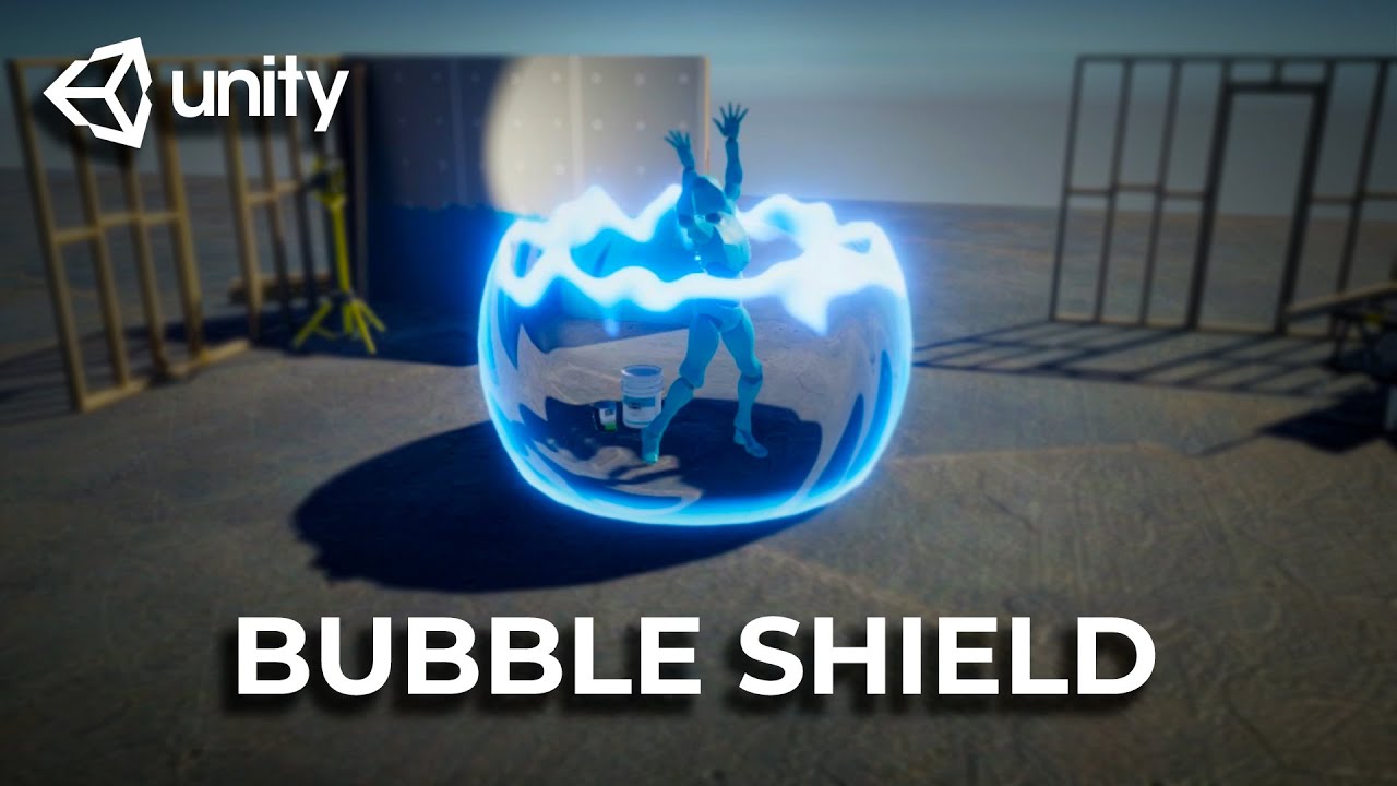
A shield effect using Unity Shader Graph and a bit of c# code.
Implements the hit effect distortion.
Download the project: https://github.com/abitofgamedev/shields
Support me on Patreon: https://www.patreon.com/abitofgamedev
Follow me on Twitter: https://twitter.com/steffonne
Follow me on Instagram: https://www.instagram.com/abitofgamedev/
Un...
Sorry, I think I didn't visualize myself the issue.
What is your dissolve size value, that could be it
The "DissolveEdgeThickness"
edge thickness default is 0.05
I'm talking of the value that is visible on the material, not the default value in shadergraph
yea .05
Hum :/
Note that you can download the project from the video, to check if their final shader is working on your side, and also side by side compare

Well, it should still work, but indeed, yields different results 🙂
I seem to be missing a lot of options that are in the video too. Don't know if I'm outdated but seems he has a Two Sided checkbox that I lack
I have a Render Face dropdown (front, back or both) but that creates some issues when the rendered faces overlap using the both option
just get this big line down the middle if using transparent shader and rendering front and back faces

not being able to render the back faces isn't the end of the world but would look a bit nicer during the transition
One way to fix this would be using a sphere mesh that already has interior faces included as well.
If you model it in blender, you can duplicate a sphere, flip normals, select the inverted sphere first then the other, and combine/join the objects together. That should have the correct vertex order so exterior always renders above the interior faces.
(similar to "Pre-sorting Mesh Triangle Order" example under : https://www.cyanilux.com/faq/#transparent-sorting)
okay thanks, i'll have a look into that
Hum, sorry, I've wrongly assumed that you had two tiles verically
No problem ^^
Can you show the part of shadergraph before the sample texture node, where you calculate the UVs ?
To avoid confusion with math, you could use a checker node if amplify has one ?
Looks like it doesn't.
You can then do this instead :
UV.v -> multiply by number of vertical tiles in the texture -> divide by two -> step 0.5 ...
A checkerboard with a X/Y count like in shadergraph would have been easier 😅
Almost there, looks like the divide by two is not needed 🤔
Unfortunaly I'm on 2019.4 and as far as i know there isn't shadergraph available with standard pipeline
No indeed.
Note that the finale multiply by 0.5 can be tweaked to controll the offset between the tiles
But at some point, like it was mentioned initially, if you want this texture to used offseted tiles, why don't you simply do it in the texture ?
To randomize the tiles color slightly to not make the texture look repeating
How many tiles do you have in the texture vertically ?
I see that you multiply by one here 🤔
It's just one square
The texture has only one single square ?
Ok, that was not obvious with the randomized dirt, sorry
My bad, should have specified that
Are you adding some tiling after this calculation ?
Like, can you show the graph until it goes into the sample texture

Huuu 🤔 how do you controll the tiling count of the texture ?
Well it just fills the whole mesh automatically
I am very confused, because this graph should just cut the tile in half if there was only one single tile in the texture 🤔
Like this?
And it is kind of doing that when looking at the preview
Yes
But I think I've found the issue :
I remade this graph
hi , could someone explain why when I'm returning return float4(0,0,0,0); I still get a black image ??

If the shader is set to opaque, alpha is ignored

thanks
wait, I've added Tags {"RenderType" = "Transparent" "Queue" = "Transparent"} to the subshader but its not invisable yet
am i missing something else ?
Set alpha blending : https://docs.unity3d.com/Manual/SL-Blend.html
Ok i turned off "Generate midmaps" and fixed it
Yes, this was one of the solution, the other one is to force the mimaps used when sampling
What's the best in your opinion?
Disabling mip maps is a easy one click fix, but manual mip level sampling in the shader will yield better looking results
I'll look into
Anyway thanks a lot for the help! I'll try to study that code to better understand what's doing
Enable "Derivatives" in the mip mode for the sample sample node : http://wiki.amplify.pt/index.php?title=Unity_Products:Amplify_Shader_Editor/Texture_Sample
Take the UV value before the add operation, pass it through DDX and DDY nodes, and input them as derivatives
Brainstorming...
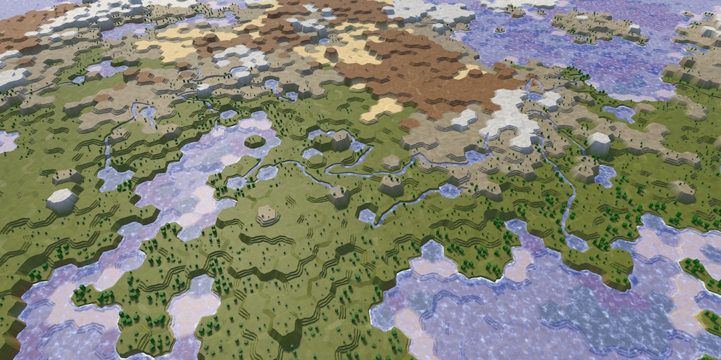
I have a procedurally generated 2D tilemap rendering tiles of specific biomes. I'd like to blend those using a shader.
I'm intermediate at best with Shadergraph. So looking for suggestions on how might I go about doing this.
I'm currently thinking about providing biome info in a UV channel and then sampling it (and neighbors?) to determine when and how to blend. I've done this before with procedurally generated meshes, populating the uvs along side the verts, but in this case I'm not procedurally generating the mesh--so I'm not sure how to align the uv indexs with the verts. I could figure out what order it populates... but I'm wondering if I should be looking at other options.
Any thoughts? Ideas? Missed opportunities? Magic words I can use in google to study up? 🙂

Do questions actually get answered here?
I don't think you can alter the tilemap tiles UV.
You can set the color, which can be used in shadergraph.
But the color is uniform for the full tile, so you'd need to be smart when storing information with it (like 1 color channel per biome index for each corner or something)
Usually this kind of things are done with dedicated blending tiles in the spritesheet, or by layering
Usually, if people have the time / knowledge / patience, yes
Layering--as in multiple tilemaps?
Not ideal, but yes, possible
You would still need transition tiles (with alpha blending), but only a set for each layer, compared to all combinations in the traditional way
Okay--thank you for your answer. I think that gives me the levers to fiddle with and explore solutions
whats the best way to add puddles
on a plane if you already use a custom shader for the material in HDRP?
Okay so I'm making a lightning dash ability and when I add a 'set position' node to my 'update particle strip'context, the strips stop showing
Hi everyone, what techniques would you use to create this cutout paper effect?

Without the outline

I tried getting the particle position for the main one and slotting it into the input for the set position node but still doesn't show till I hide the set position nnode
is it not a possibility to hand-paint it?
This one is hand painted, but my game has user generated images
it's not really feasable in a shader, maybe a voronoi algorithm could do something similar, but it would be way worse quality
Hello guys, i have a problem with my Shader Graph Shader. I copied it from this website https://timcoster.com/2020/07/18/unity-shadergraph-starfield-tutorial/
i already checked and i made no Error copying it. Im using Unity 2022.2.10f1 URP. It gives me this error. I did not write any code for the Shader Graph and did not modify the code. feel free to ask if you have any questions

you'd probably have to do it in a script, maybe a compute shader could assist some of the calculations
I thought about using Marching Squares or Voronoi
marching squares couldn't really replicate your shape, I guess it should sortof follow it
even in smaller concave arreas
This seems to be the way
hmm
what if
you do marching cubes
or squares
sry
you get edges out of it
and you nudge the vertices of the edges towards the nearest pixels
that are not transparent
so kinda like have a nudge matrix, you sample all around a vertex, and summarize directions where there is a solid pixel
and maybe even merge some edges
to have a more variable sized cut
but only merge the ones that don't differ much in angle, so you keep the sharper edges
whats the best way to get this look in unity

@atomic flint
it uses a perlin noise for another material that is basically to simulate wetness
Marching squares seem to be less random, easier to control like an outline
anyone know of anything i can use to do this in unity? ive never messed around with shaders.
any idea why this transparent sphere starts to not render and just disappear if i go out far enough or have my Max Tri Size set to a lower value?

Something like this 🧐

ideally you'd get some seamless noise lookup texture and use that instead of perlin in shader
yeah and you could merge some of the edges so it has more randomness
maybe a bit more resolution and a lot more merging
ah okay, I just have one problem which is that i already use another custom shader that blends the material to get rid of the repeated pattern
but i cant add anything on top of that
is there any other way to add puddles and things/random patches of wetness?
you can do that 😄 all shaders are editable
i have noted that this has to do with size and my distance from the object. seems like it doesn't play well for large sizes when I want the sphere to act like a billboard, any tips?
idk how to do that lol ive never messed around with shaders
how large is it
great weather for learning some shaders 😉
where do i start 🤣
Around 160 scale it starts to glitch out
ive tried looking for tutorials of what im trying to do but nada
i'm considering just transforming it into a 2D animation and rolling with that
- make a noise texture display on your object in shader graph
- lerp between two other textures using the noise in shader graph and display the lerped result
- create an unlit shader and do the same
- try to add another vertex input like vertex color into the shader

im making a vertex displacement shader and im trying to move the vertex relative to the normal, but its not giving the desired result, anyone done something like that before i can look at?
some ideas
thank you
A collection of tutorials for people who want to learn C# and shader programming in Unity. Useful to both novice and experienced developers.
more random ideas
some will have elements of what you need
you'll have to puzzle together yiur shader knowledge 😄
but these tutorials are fun and easy to follow for the most part
make sure the vertex is in the same space as the normal, for example object space
nice thank you
i think they are both in object space, i have tryed converting the normal to and from object space to
screenshot pls


// Upgrade NOTE: replaced '_Object2World' with 'unity_ObjectToWorld'
Shader "Unlit/shater"
{
Properties
{
_MainTex ("Texture", 2D) = "white" {}
_vel("movment", range(0, 100)) = 1.0
}
SubShader
{
Tags { "RenderType"="Opaque" }
LOD 100
GrabPass
{
"_BackgroundTexture"
}
Pass
{
CGPROGRAM
#pragma vertex vert
#pragma fragment frag
// make fog work
#pragma multi_compile_fog
        #include "UnityCG.cginc"

        struct appdata
        {
            float4 vertex : POSITION;
            float2 uv : TEXCOORD0;
            float3 normal : NORMAL;
        };

        struct v2f
        {
            UNITY_FOG_COORDS(1)
            float4 vertex : SV_POSITION;
            float3 de : TEXCOORD0;
            float4 grabPos : TEXCOORD1;
        };
        sampler2D _BackgroundTexture;
        sampler2D _MainTex;
        float4 _MainTex_ST;
        float _vel;

        v2f vert (appdata v)
        {
            v2f o;
            o.vertex = UnityObjectToClipPos(v.vertex);
            o.grabPos = ComputeGrabScreenPos(o.vertex);
            o.vertex = float4(mul(unity_ObjectToWorld, float4(v.normal, 0.0)).xyz * _vel, 1.0) + o.vertex;
            //o.uv = TRANSFORM_TEX(v.uv, _MainTex);
            o.de = v.normal;

            UNITY_TRANSFER_FOG(o,o.vertex);
            return o;
        }

        fixed4 frag (v2f i) : SV_Target
        {
            // sample the texture
            fixed4 col = tex2Dproj(_BackgroundTexture, i.grabPos);
            col.r = 1;
            // apply fog
            //col = i.de;
            UNITY_APPLY_FOG(i.fogCoord, col);
            //what

            return half4(i.de, 1.0);
        }
        ENDCG
    }
}
}
its probs not world space tho. but that was the neasrest to looking good
aaaaand none of them are in object space
one is in clip space the other is in world space
modify v.vertex before converting to clip pos
and don't touch v.normal with the world space matrix mul thingy
or convert back after doing the _vel thingy
If this is a sprite, you could use the sprite editor to manually draw out (or generate) the mesh shape (aka "Custom Outline") - https://docs.unity3d.com/Manual/SpriteOutlineEditor.html
Then use a shader that lerps the alpha channel of the texture to white, rather than using transparency.
they need it to be procedural for user generated content unfortunately
yeye ik that i was just trying all possibility's with spaces before asking strangers on the internet. it look like its workingish, good enouth, im just dumb with the clip space
nice
thx alot
np
Ah okay, missed that part
I don't think this works with images generated at runtime, which is my situation
But Thank you
It would be useful if I could use this engine feature at runtime
can someone please help me?
hi,
could someone help me understand what causes the colors in this ShaderToy?
https://www.shadertoy.com/view/ldyczd
what makes the inner part Red ?
what makes the outter part Red ?
What makes all the Blue stars ?? can i change them into a different color or just remove them all together ?

I remember some shader graphs getting just bugged out for some reason
maybe try to reimport?
The O output is the colour being displayed. Line 25 is responsible for the red outside the star shape, Line 26 is responsible for the blue lines.
Have you tried opening and resaving the graph maybe?
thanks , still somthing is not right
when i removed both lines (25 and 26 ) I can still see the star in the middle but in white!

That's because of line 22
{
   float t = mod(iTime,8.),
         N = 3.+5.*min(t,8.-t),
         r = 1.,                   // radius
        r0 = .5;                   // relative interior radius

    vec2 R = iResolution.xy;
    U = ( U+U - R ) / R.y;
    float a = atan(U.x,U.y), l = length(U),
          b = 3.14159/N,
        tb = tan(b),
       // s = sin(b); // if control by peak angle
          s = (r0 * tb)/(sqrt(1.+tb*tb)-r0); // control by r
    a = mod(a,2.*b)-b;
    U = l * vec2(cos(a),sin(a)) / cos(b);
    U.y = abs(U.y);
    U.x -= r/cos(b);
    l = -(s*U.x+U.y)/sqrt(1.+s*s);  // true euclidian distance ( +: inside )
  //l = -(U.x+U.y/s);               // field fitting radial distance ( +: indide )


    //O = sin(30.*O);
    if (l<0.){ O=vec4(1,0,0,0);}
    else{O= vec4(0,1,0,0);}

}```in the if else you can replace the red and green
the last two code lines
l is responsible for telling how far away you are from the stars edges and goes negative outside of the star I guess
that shouldn't be too big, but very far away objects can act wonkey because of floating point precision
didnt fix it
depending on the math you're doing, you can run into precision problems very quickly
i have a shader that computes the angle between the camera's forward vector and a vector pointing to a pixel on the screen
it freaks out surprisingly quickly
if you are making a massive universe with thousands of kilometres size make sure to center the map around the player
Shader "SuperSystems/Wireframe-Transparent-Culled"
{
    Properties
    {
        _WireThickness ("Wire Thickness", RANGE(0, 800)) = 100
        _WireSmoothness ("Wire Smoothness", RANGE(0, 20)) = 3
        _WireColor ("Wire Color", Color) = (0.0, 1.0, 0.0, 1.0)
        _BaseColor ("Base Color", Color) = (0.0, 0.0, 0.0, 0.0)
        _MaxTriSize ("Max Tri Size", RANGE(0, 200)) = 25
    }

    SubShader
    {
        Tags {
            "IgnoreProjector"="True"
            "Queue"="Transparent"
            "RenderType"="Transparent"
        }

        Pass
        {
            Blend SrcAlpha OneMinusSrcAlpha
            ZWrite Off
            Cull Back

            // Wireframe shader based on the the following
            // http://developer.download.nvidia.com/SDK/10/direct3d/Source/SolidWireframe/Doc/SolidWireframe.pdf

            CGPROGRAM
            #pragma vertex vert
            #pragma geometry geom
            #pragma fragment frag

            #include "UnityCG.cginc"
            #include "Wireframe.cginc"

            ENDCG
        }
    }
}
Spheres with sizes starting from 160-170 start getting glitched like this. What's the issue here? I changed into a higher poly sphere and it fixed but i want a sphere that looks like that, very wireframe like and basic


I believe I have found a glitch in unity's shader graph after experimenting a lot. what's the process with reporting it?
This is the code its referring to void SG_StarGrid_99c508c1f0e11e34eb42367192d14523_float(float2 _FractionedUV, float2 _NormalUV, float _StarSize, float _StarFlareScale, float _FlareBrightness, float2 _GridCellOffset, Gradient _Gradient, Bindings_StarGrid_99c508c1f0e11e34eb42367192d14523_float IN, out float4 Texure_0)
If i look at the shader graph code
i dont know what possibly could cause the error
!bug

🪲 To make bug reporting as quickly as possible, we made a bug reporting application for you. When running Unity choose Help->Report a Bug in the menu, or you can access it directly through the executable in the directory where Unity is installed. It will also launch automatically if you experience a crash.
📝 If your bug report is to do with Documentation, either an error, typo, or omission, you can report it by scrolling to the bottom of the page where you found the issue and click ‘Report a problem on this page’!
💡If your report is to do with a new feature idea, you can check the Unity Product Roadmaps page to see if your idea has already been planned.
For more complete instructions on how to report bugs, access: https://unity3d.com/unity/qa/bug-reporting
plsi'm still having the same problem
Between preview and scene the main difference is that you're using a mesh with likely different mesh data, a different scale and that the world position and viewpoint are different
Those can completely change how an effect appears
But why can it display it without errors in main preview?
But on a material it gives errors
I missed the point that there were errors
I'd try cutting out nodes from the output, saving and checking again until errors disappear, then start adding them back in to figure out where the problem lies
i made a glass shader that refracts a while ago and i decided to import it into another project. but for some reason instead of doing what its supposed to it just turns into a solid colour provided by the color property. why?

As the graph uses the Scene Color node, the Opaque Texture option on the URP Asset should be enabled for it to work
thank you
what can i do to improve the color replacement

increasing one or the other of range and fuzziness messes up the surrounding image a lot
Use some different technique, like premultiplied color masking
https://bgolus.medium.com/the-team-color-problem-b70ec69d109f
You could extend the example implementation to have multiple colors by using masks with more than one color channel, effectively storing multiple masks in one
are shader one for whole game with IF Define actually better than like let's say multiple shader?
how many shader do people usually write per game, is it better to make many and more specialized shader or make as less as possible?
i've been working on this cloud skybox material, which looks quite good in game with the exception of some ugly UVs at the top of the sphere. it's made with this subgraph and graph combination, where the subgraph is calculating the UV coordinates for the Tiling and Offset nodes in the main graph. I'm not really sure what's causing the sphere to look like this at the top


Jesus save us
the replace color node shouldn't have been born
I don't think I've seen anyone use it who actually needs it
it's a matter of ease-of-use, both are fine, it's just easier to have multiple options in a shader, like for example URP has variants of the Lit shader without any additional lights for saving performance. Whenever there are no lights lighting an object a different shader variant is used - same goes for shadows, why calculate them when you can eliminate them from the shader using a different variant?
so, if you have many different shaders doing very different things keep them separated, but when you would like to do optimizations like this, or add other optional features to it use variants
with IF defines
just keep in mind, you'll have 2^n amount of variants compiled for a shader that is using n amount of ifs
which usually increases build times
also, some variants are automatically stripped if unused, so its not that big of a deal
I see... thanks for the info
np
render order(?) stacking(?) question, I have the use case that I want to darken large groups of many game scene objects 🤔
As in like, isolate "just this group of X" gets to remain bright while the others all dim.
All the materials are transparent with additive blending however, given this constraint is there any known smart way to essentially grab a bunch of things and make them all darker? Either by changing alpha, changing color, or somehow adding black?


end result for example would be making the bottom two layers in the left-most image darker so the top most one is clearly brighter
I tried adding a big black quad between them but even when scrubbing sorting priority around, its really finnicky and inflexible to get it to darken what I want and not other things
I could pass darkness values into materials but I feel like that might spawn tons and tons of new clone materials and kill the rendering?? Or is there a non stupid smart way to pass values in, does the material property block not kill my render budget?
I considered moving everything I dont want to be bright to a different layer, but I am already using a bunch of layers to control how it looks visually so I'd have to add like 5-6 more layers just to have a 'dark' version of all of them, not ideal
i can't believe chat gpt managed to give me a correct answer for a problem i had with a shader not having proper transparency
but i guess it wasn't a complex issue so it was able to solve it
as long as you didnt tell chatgpt to create shader from scratch then it's fine
that thing is broken
probably need another year
yeah wasn't from scratch
so I have a problem. This shader graph has been working great for me until i updated to 2022 lts. When I upgraded, 2 sides started being uninitialized, 2 became blue, one became red. Can somebody help me? Here is my shader graph, and here's what it looks like now


I have no idea what to do
Changing the surface type to Transparent should fix this iirc
where do I do that? I have no experience with shaders at all. Someone made this for me, and theyre no longer available
@regal stag
found it nvm
OML IT FIXED IT
thanks
I didn’t know of any other way
hey im adding an vertex shader effect to all my materials and trying to make sure they all keep the same fragment shader effect. I know that it works with BaseMap, BaseColor and Smoothness. It's not clear what i need to do with BumpMap and Parallax/HeightMap.

I tried to apply shader graph to my VFX graph that would randomly either set or change the color of different pillars, however I have got this flickering issue. It doesn't seem to be the problem of particles stacking with each other since the issue occurs even if there is only one particle. Does somebody has any idea what may it be?

This did the trick for whatever reason. I think it might have been the VFX graph was returning both positive and negative values at the same time, but I am not sure

I've set up the animal crossing rolling world camera and was getting a weird issue where objects near the top of the screen were getting culled.
I came across the Bounds section in this article Cyan wrote https://www.cyanilux.com/tutorials/vertex-displacement/ which made a lot of sense. As far as I understand, the solution proposed is to recalculate the bounds of the meshes in view by destroying and creating a new mesh. If this needs to happen for each gameobject every time the player moves, wouldn't that be pretty expensive computationally? I'm wondering how animal crossing manages this on the switch? Could it simply be clever optimisation, knowing the exact conditions in which objects might get culled, if they're on an elevated level...
Maybe it just being meshes not colliders it's fine?
Perhaps I've misunderstood something or am overblowing how expensive this would be, just seems crazy to me that AC is doing it on the switch
Material property blocks and enable instancing for the material. By the way, always use property blocks to change materials, changing them directly results in the asset getting updated too, messing with version control if you have any. Also, if you still want to darken an area you can use other blend modes than just add and alphablended you know https://docs.unity3d.com/Manual/SL-BlendOp.html https://docs.unity3d.com/Manual/SL-Blend.html
it's screen space ofc, you can't darken an actual 3d region with this
also, by looking at your setup you could base your darkening on height and might not even need any of this
property blocks, Ill look into that 👀
good point about height, I could sample world position as well
maybe you could pass a global brightheight variable and use that in all shaders
that way you only need to update once
@cosmic prairie @tight phoenix Worth nothing, Material Property Blocks are okay for Built-in RP, but I'd avoid if in URP or HDRP, as they aren't compatible with the SRP batcher so it'll be more expensive to render.
Maybe could have a darker version of each material and toggle them in a C# script. Perhaps a little more complicated to setup, but that way it's not a material instance per object (like renderer.material would create)
(edit : Oh, Spazi already suggested the same thing in #💥┃post-processing. Should avoid cross posting questions..)
The mesh is only created once, not every frame. But yes, for every gameobject that's probably not good. It is actually now possible to override the Renderer.bounds or Renderer.localbounds instead though (as of 2021.2+?), I should probably update the page to include this.
oh great, wasnt aware of that! Thanks that sounds like it should be far better
Does anyone happen to know how I would use GetColor to get the color that is currently being fed to the master stack? since i switch between two colors using a sine during runtime i can't specify a global property to access for the current output in my script, i can't name both colors _Color...

Properties are for passing values into the shader, not out - that's not really possible. If you need the colour on the C# side you may need to replicate whatever Sine calculation you have in the script and calculate which colour should be used there, then pass it in through a single colour property. Assuming it's the same colour for every pixel/fragment that is.
@cosmic prairie @tight phoenix Just to add my experience:
As a workaround for this, in my project I have non-instanced materials for static objects, instanced materials for objects that move but otherwise not changing the material, for those objects i want to change at runtime i use a basic VFX-Graph mesh / quad spawner, hook up the appropriate shader graph then simply change those values at runtime as VFX-Graph uses the jobs system (i believe) so it's quite performant, you can also use Frustrum Culling and other stuff to make it even better if required. This bypasses the need for MaterialPropertyBlocks and keeps SRP batching intact as well as batching all your VFX-Graph meshes (as long as you set them up correctly), before I was seperating each part of the meshes that change at runtime, meshcombining them then using a MaterialPropertyBlock on them, which was quite a time consuming workflow.
Also thanks for the advice Cyan, I had a fear i wouldn't be able to do this, i wanted the sine inside the shader itself if possible instead of doing it via script, so gutted i can't get the current color as i was trying to get a point light to match it for ambience.
Hello . how do we make a global constant ?
I've tried const float defaultX = 123; >>> didnt work
then also tried #define const float defaultX = 123; >>>> didnt work
i use defaultX in many functions , i dont wanna re write them in every function , is there is anyway to do it ?
nvm found it
#define defaultX 123
In the global scope you'd need to mark variables as static if you want them to keep their value.
But defining as a macro instead works too.
oh , so u are suggesting that we could state it like this static float defaultX = 123; ?
Yea, that should work iirc
sweet, thanks ❤️ ❤️
I wanted to make a simple noise so I copied the code from here https://docs.unity3d.com/Packages/com.unity.shadergraph@7.1/manual/Simple-Noise-Node.html
but it just gives me a complete black output
is there something that i am missing ?
Sorry nevermind, i miss spelled a variable
I am having trouble understanding the Layer in the Post Process Layer.
Only if i set it to everything i see the post processing effect.
If i set it to custom layers that i have made, i dont see the effects
I actually fixed it lol


You need to change the Surface Type from Opaque to Transparent, under the Graph Settings
now why the Alpha clip thershhold is like that ?

For that to work, Alpha Clipping needs to be enabled in the Graph Settings.
Note that if you just want clipping, you can keep the graph Opaque. Only needs to be Transparent if you need partial alpha values.
But I can't find the PBR grath
PBR Graph was renamed to Lit Graph
Is someone able to confirm that the InstanceID node in ShaderGraph should be the actual index of the instance when rendered with like Graphics.RenderPrimitivesIndexed Right?
seems silly, they should be batched > : (
hey so why do simple 200 line fragment shaders take 3+ minutes to recompile sometimes, whereas other times the exact same shader takes 1 second? unity 2021 and 2019, same thing in both
its pissing me off big time
https://paste.myst.rs/chcgeap7
this is the shader in question
a powerful website for storing and sharing text and code snippets. completely free and open source.
@cosmic prairie Don't post off-topic gifs
i have a question
creating a dynamic NOISE with shader VS using a TEXTURE as a noise , which is more optimized ?
How do keywords work in shader graph? I am hoping to use a boolean keyword to toggle apart of the shader on/off so that a simpler variant can be used on slower computers. Is there a tutorial for this?
texture
lookup textures r usually faster than calculating something more complex
Depends on the noise and on the device. Doing shader based noise is heavier on the GPU cores, texture based is heavier on GPU bandwidth.
When starting out I'd say use what is easier and when polishing stuff up test both and see if it matters
For that use a boolean with a branch instead of keywords
Afaik branch node evaluates both sides so it wont make the performance any better on slower devices, just even worse
anybody know how to disable this? i dont think this is culling, becaus i didnt even make my gameobj static yet (i scale gamobj using shader)
check camera settings
it has an automatic culling effect
this one?

tried turning it off (it was on) but nothing change
odd
Note the "bounds" of your skinned mesh renderer
If those are outside of the camera's view, the mesh gets frustum culled
i wouldn't know what's causing it then
Oh and if you scale the mesh using shader, that will not update the bounds
Bounds are calculated on the CPU and have no knowledge of how the shader might be moving the vertices
oh yep, you are right, already set it to 100 for the XYZ,turn out when using "update when offscreen" make the bound extent cant increase.
after unchecking it, now it fixed
I think modern systems can handle branching better. Otherwise just make 2 shaders and swap the shader on the material or swap the material completely
They can but the branch node may not count as branching at the low level. The generated code example at the docs page says this Out = lerp(False, True, Predicate); and I think I have seen it compile to ternary operator which if I remember correctly does never produce branches, instead evaluates both sides (in hlsl)
From what I read compiling as lerp is the better handling compared to an actual GPU branch
But I also hear that if the predicate cannot change per fragment such as from an unchanging property then that's somehow better
The new branch node uses the ternary operator so modern shader compilers can compile it in ways branching doesn't really happen
I'm not an expert, but there is a lot of info here: https://forum.unity.com/threads/branching-in-shaders.1231695/

Unity Forum
I found a Blogpost about branching and why and how it should be avoided....
But if you want to completely avoid any branching or lerp, make 2 shaders and swap them dependant on settings used
I mean if the branching doesnt happen, its true disaster for the optimization, it would then end up evaluating both branches and lerping to get the right one of them which means that when they want to save some performance by having cheaper version of the shader, in the end they would do the calculation of both cheaper and heavier shader. If it happens to compile to true branching, it would potentially be really good for performance. At the end I see no reason not to use keywords for that as they suggested in then first place, that is very same as having two shaders and swapping them. That would make sure no extra stuff is evaluated at the branching state
I dont really know how to use keywords in shader graph but ik its possible
this is gonna sound simple, but anyone got any easy tutorials on making a shader that makes it so that the object has a alpha that follows a gradient of 1(opaque) at the bottom and 0(transparentZ) at the top?
specifically i wanna do a lightshaft like this

It's mostly just create the Boolean Keyword, set fields under Node Settings, drag it into the drag and connect it up (probably your calculations to the On port, and some default value to the Off. Then combine the result with other parts of the graph)
This might help for more info - https://www.cyanilux.com/tutorials/intro-to-shader-graph/#keywords
If this is for something 2D you could just apply a lightshaft texture to a quad. Could maybe also work for 3D if you rotate it to face the camera.
Otherwise if the lightshaft mesh is a cone and is UV mapped, can use a Fresnel Effect to fade the sides out and probably the UV.y (or 1-UV.y) to fade the top/bottom.
or implement volumetric lighting
i decided to use a particle system

Hello! I've been trying to figure out why my shader would work with a standard unity cube but not with a mesh.
In this case, the cube is dissolving as expected, near the centre of the screen, but the mesh isn't applying the simple noise, only the centre gradient.

This is what the shader is looking like

(A side question might be, if anyone has any suggestions on what might fix the noise not showing up on the preview, unity 2022.2.16)
The noise is using UV coordinates from the mesh data. For that to work, you need to make sure your model is UV mapped/unwrapped
Right, that makes sense. I'm using prototype assets from the asset store so no idea if they are unwrapped or not
Any pointer on how I could change this to a screenspace noise?
Nevermind, I just need to feed in the screen uvs
The cube is a mesh
Most commonly what's different about a custom mesh is the UVs and scale
(scrolled up again)
Thanks @regal stag!
Thanks @grizzled bolt, haven't wrapped my head around shaders much yet, takes some time to shift gears I feel like, but that makes sense.
When I said mesh I meant custom mesh, my bad.
In this case I just want to fade things out in the center of the screen if they are obstructing the view of the player, so I don't need to depend on the mesh uvs really
A curious effect is that the screen is obviously 16:9, which seems to make my gradient skewed. Since I'm calculating the length, instead of a circle, it's an oval.
I'm guessing the direction I need to go to make this a circle is to somehow remap my uvs in such a way that both the 16 and the 9 match up to the 1:1 ratio of the uvs?
Am I thinking about this correctly?
https://docs.unity3d.com/Packages/com.unity.shadergraph@14.0/manual/Screen-Position-Node.html
You have multiple kinds of screen UVs to choose from without having to do any math
Can make a ratio using values from the Screen node. iirc I usually use something like * float2(1, Width/Height)
Thank you 😊
Got it working with this tip, thank you!
Hey everyone! Im pretty new to Shaders, can anyone give tips on how to make a transition effect between background images with graph shader. I want it to look like a powerpoint circle expanding transition. Basically from the center (Player's position) The background image should change like an expanding circle into the new one
Probably something like lerp (or branch) dependant on the position where you change the parameter using C# or using the time node
Yeah Lerp was the solution but why does it look so different in the preview compared to how it looks like in the scene?
Here in the preview its correct, the blue is the new background but in the scene it just abruptly changes the image for some reason

So question, If I have a parameter that is always the same on a compute shader, let's say that an int is always 10, for all the calls, (but it's a variable because it might change before the game starts) can I set it once only, and then run the dispatch as many times as I want changing other variables, right?
Yes
Does that also apply if Im dispatching the shaders from a command buffer?
Because I tried setting the variables on the compute shader, and then run a command buffer, but the variables where no longer set there
That I'm not certain of.
Hey there! I made a shader I like for fading objects when they are obstructing the player. This fade is controlled by a float that ranges 0..1
My question is, since say, all trees share the same material, if I change this float value for the material, wont all trees fade, instead of just the one that I detected as obstructing the player?
Thanks!
They all will, if it's controlled by a property
If you're on BiRP you may consider using material property blocks, and if on URP/HDRP pooled material instances to control individual trees' appearance
Another option is to make a fading script that works by view direction and positions and doesn't rely on changing properties individually
HI Shader Peoples -- I have a question posted over in #archived-urp if some of you who are good with shaders could check it out I'd appreciate it
Thanks Spazi. I did a quick google and apparently material property blocks seem like a simple solution that work in URP
It's not recommended for URP because it breaks SRP batching, unlike material instances
I see. Is there documentation available for material instances? I did a google search but nothing came up
Hello
Bascially when you modify Renderer.material Unity automatically creates a material instance for that object, but if you want to optimize it to reduce the number of loose material instances you can instantiate them yourself with instructions from here
https://discussions.unity.com/t/changing-one-material-instance-affects-all-instances/115874/4
and use generic pooling techniques to swap between them when you need materials that are safe to have their properties changed at runtime
I was playing Alan Wake, and like almost everyone, i was amazed by the flashlight mechanic.
Specifically when it reveals hidden yellow arrows that point to loot caches.
I did some searching, and found two videos that recreate this mechanic. One using AmplifyShader the other one coding the shader directly (not using shader graph).
Did some more searching, and it turns out you need some specific lighting properties(?) that aren’t available in shader graph so you need to make custom shader blocks.
I was wondering how do i go from knowing nothing about shaders (Only experienced ShaderGraph on the Unity Learn Creative core) to understanding the lines of code in that shader, some really 30 lines maybe.
Edit: forgot to mention i’m using URP Unity 2022.3
Talking about this one in particular:
https://gist.github.com/runewake2/2a979d6bc91adc7ce693a5c00af8bed1
By World of Zero on YouTube

Gist
Shader that only renders when inside a light cone. - RevealingShader.shader
Really it's only a few lines that are actually important if you want to recreate this in ShaderGraph. The surface shader is already fairly similar to the Lit Graph.
float3 direction = normalize(_LightPosition - IN.worldPos);
float scale = dot(direction, _LightDirection);
float strength = scale - cos(_LightAngle * (3.14 / 360.0));
strength = min(max(strength * _StrengthScalar, 0), 1);
o.Emission = c.rgb * c.a * strength;
Functions like normalize, dot cos, min and max all have exact node equivalents. The rest here is some basic math nodes (multiply, subtract, divide).
The variables that start with _ are all properties, can create those in the blackboard. There's likely a C# script setting them externally - you'll need to look at the World Of Zero video for that.
IN.worldPos will be the Position node, set to World space.
o.Emission would be the Emission port in the Master Stack when using a Lit Graph.
The shader is also Transparent, can change that in the Graph Settings.
I think you only need custom lighting stuff if the revealing light needs to be affected by shadow casters
Or for it to support multiple lights too.
If those are important, I've got some subgraphs that handle a few things - https://github.com/Cyanilux/URP_ShaderGraphCustomLighting
Thanks! I’ll read/watch dome tutorials on HSLS/ShaderGraph and attempt to recreate it.
Makes sense. So if a shadow caster gets between the light source and the "texture" I’m trying to reveal, it reveals as if nothing is in between ?
Oh wait! So this is yours!
https://www.cyanilux.com/resources/
Amazing!
Another question, why would it not work with shadow casters without custom lighting stuff?
Useful Links to Resources/Tutorials/Docs related to Unity or Gamedev
Yep that's my site 🙂
The code you shared is only doing some math based on a light direction/angle (passed into the shader via properties), it's not taking any shadows into account.
For that you'd need to sample the shadowmap. It might be a little difficult to get the specific one used by the flashlight if there's multiple point/spot lights in the scene though. Might need to use light layers.
Taking shadows into account suddenly makes the whole thing seem very complicated.
I’ll try and do things one step at a time. Thanks a ton for the help, and for the website! You’ve been extremely helpful guys.
Could someone help me understand this
I set a temporary Render Texture with a command buffer on the event AfterDepthTexture
I try to retrieve it on another command buffer, with this
on the event AfterForwardOpaque
However it throws me
Im on unity 2022.3.4f1
is it physically possible to do parallax depth on surface normal vectors? As in like, not need to use the UV map coordinates because those cause discontinuities

like not have this occur 🤔

this is XY tbh
what I really want is for this to look.. better

its fine, its very nice, but I think what is missing is some kind of index of refraction

like this has IOR-ishness to it
but this looks weird or completely different based on the mesh

actually cranking up the IOR I think the real problem is that this isnt normal vector based at all, its a cube, which is why it looks best on the cube

i have this that gives paralax coordinates for textures, but its based on UV space and returns UV space values which arent useful since I am not trying to texture map it
and I cant seem to figure out how to turn it into a float value

I guess I need to... find the math to... turn a UV into a square mask the range of 0 to 1 white, anything greater or lesser black maybe?
but I dont think thatill solve this


yeah this is sorta it except it needs to be based on the surface normal instead of UV coordinates
I guess what I am trying to do is... offset the surface normal value.. by.. it's own surface normal value? .. relative to the view angle?
is that even what I am trying to do?
I'm just trying to make it look less shit but I don't know how to do that
How do I paralax on Vec3 coordinates instead of UV coordinates?
I cant find any tutorials for that which aren't about then mapping a texture
getting more frustrated and distressed because something is "wrong" with it, I hate how it looks but I don't know why or how to fix it, and this feeling only makes that much harder to make any progress, and I feel @#$@^ing miserable that I spent all of my sunday, what little precious free time I have, achieving abosofuckinglutely nothing :/
If you get Vec3 from your parallax, you can use that Vector to sample Octahedral mapped texture or cubemap, which could produce seamless mapping
how would I shift this up, shrink it, etc.?

there doesn't seem to be any way to manipulate it after sample texture 2D?
I need some help guys. I m participating in an game jam with the theme 2 Colors. Is there an way to flip the color in an scene with one simple shader and like an code, for example i want the colors to flip if i press the space bar.

Thats the Scene im working with.
I know i could do it just with just an script but that script would have to be on every gameobject and that would make level building kinda ass.
I'm no expert at shaders or shader graph, but would something like this work?


@jolly oak
Would you know how its done in the text based shader method, if not than its ok
no but I'm sure it's easy enough to find out how to write each of those nodes in shader lab. Check the docs, it often gives example code: https://docs.unity3d.com/Packages/com.unity.shadergraph@14.0/manual/Branch-Node.html
ok thanks
what pipeline?
Anyway, because you're using only two colors, and you want to "flip them" around, you could have two shader global properties...color1 and color2. Draw all your objects "normally"...in other words...the black ones in the pic would use color2 and the blue stuff color1, for example. Since these are shader globals, you don't have to reset them on each object.
In script, when you want the colors flipped, just swap the colors in the two globals...so color1 would become black, and color2 would be blue. You could also have an internal C# bool property for "colorsAreFlipped" or whatever.
This way, you draw them with the right colors the first time, and you don't need some special post processing shader pass to flip the colors around on the entire screen.
ALL your materials would have to use these shader globals for their color palette.
hi guys, i was wondering if there is a store for unity shaders? i just want a basic looking ring/circle shader, im making a basic battle royale game to test my networking knowledge, but icant find an off the shelf asset to buy 😦
Unity asset store
there arent any on there 😦


Hi, would there be any reason that a MRT (multiple render texture) setup would work on AMD, but not Nvidia? On AMD it draws to all render textures fine, but on Nvidia only the first rendertexture is written to...
nvidia (renderdoc)

amd

same in frame debugger, but i cant show all the textures at the same time xp
Which Unity version and which render pipeline is this?
2022.3.4f1, built in
There is no 2022.34 version afaik. Do you mean 2020?
If so, try the latest 2020LTS, otherwise go to the latest lts of that yearly release. There have been some RT fixes I think.
If that doesn't work, make a bug report. Maybe trying on URP might work after you made the report, but not too sure
there was a dot between 3 and 4 oops
but yes this behaviour was replicated on 2021.3.6f1 and 2022.3.4f1
strangely i cannot repro it using a empty project
but the empty repro project has all the rextures using the same format, and the problem one has all three with different formats (albeit with the same bitdepth)
so ill try that
Owh that's interesting yeah. Maybe try to compare the settings and setup?
that was a dead end sadly
ok ive copied the multirender shader into the empty project and it works
im so confused
Try asking on the forums maybe
Im trying to readback data from a compute buffer that is being set inside a command buffer
        AsyncGPUReadback.Request(isThereGrass, (AsyncGPUReadbackRequest request)=>{
            if(request.done)
            {
                NativeArray<uint> array = request.GetData<uint>(0);
                EmptyChunk = array[0] < .5f;
                array.Dispose();
            }
        });
this was my idea, but i guess im missing something?
Aaah, I had to use the buffer
        buffer.RequestAsyncReadback(isThereGrass, (AsyncGPUReadbackRequest request)=>{
            if(request.done)
            {
                NativeArray<uint> array = request.GetData<uint>();
                EmptyChunk = array[0] < .5f;
                array.Dispose();
            }
        });
The Standard one if you start with an simple 2D Project, i now got like a really basic one through ChatGPT and im applying it with and ShaderHandlerScript to the Camera. But its not really working, if i move one lets say color 1 the player movement lefts an trail of its self. But this disappears if you flip the colors again, also just on color 1 which is weird. And im flipping the colors through an different script kinda like you explained it.
what is the downside of having too many shader variant? it's doesn't effect performance right? only increase on app size and build time?
If you have materials using different shader variants they won't batch together, so that could affect performance.

Hey i'm trying to use an add node here to create a blue circle in the middle of the texture, but it's not getting that result. does anyone know a way i could do that?

Hey guys, quick question!
Is it possible to bind a Float2 array to a material?
Right now I am just using a flat float array, and i know float4 is possible, but this is all limiting in my case.
Thanks in advance guys
Lerp should work. Using the black/white circle mask (before applying the blue colour) in the T port. Then A set to the texture result and B set to the blue colour.
yeah that's perfect, thanks
Unity only supports float or float4/Vector4 arrays afaik. I'd probably stick to the float array.
I guess an alternative is using a ComputeBuffer/StructuredBuffer if the target supports them.
WebGL, so sadly no 😦
Otherwise I would have used buffers a long time ago haha
In shader code is it possible to index into a float4 to get the individial values? like an array? (instead of .x etc)
Yes, you can use someFloat4[x] with x being a value from 0-3
Thank you
found out:
Blend Modes are different across cards for MRT, changing the blend mode to nothing solved it
AMD will treat Alpha as 1 if alpha doesnt exist e.g. with R16G16
Nvidia will treat alpha as 0.
On AMD it drew things fine with the blendmode
on Nvidia it was all black squares
hope this helps someone in the future. 
Interesting, thanks!
Could you file a bug report so it can be fixed or at least throw a warning?
oh where do i file tht
Hey everyone, I've been struggling for a long time with making a shader that draws a line around objects.
There is a problem with my shader and I can't understand what is causing it. As seen in the video, the width of the line changes depending on the x axis of the plane's rotation. What should be happening is that when I change the x rotation of the plane, the line just rotates while keeping a uniform width.
I've provided 2 screenshots of the shader and a screenshot of the script responsible of setting the values for the shader (the problem is with the shader, the script is totally fine).
I would really appreciate if anyone could look at the shader and help me solve this 😃
The second part of the shader is provided just for clarity, as the problem lies somewhere in the part of the shader where all the math operations are, and not the part where I just change the colors


The issue is about how to apply the line width : you are adding a float to a vector -> it add the width to the 3 components of the position
I don't like the look of Adding/Subtracting the line width (which is a float being converted to a Vector3). Maybe you want to shift it along the plane normal direction, but it's probably equivalent to just handling the plane intersection once (in the middle, so without add/subtract), then use an Absolute and the line width as the Edge input on the Step node.
What should I do instead of that?
I would suggest to change a bit how you do the intersection. I was going to say like Cyan, but he beat me 🙂
I hope it's not too much to ask for, but could you send an image of how that would look like inside of the shader graph? I'm not sure I understand what you're saying

Took too long to even get unity open 😆
That's my secret, I always have Unity open
ok so my voranoi texture is always facing the camera was wondering if i can make it completly indipendent of the camera
so that the cuttouts don't change where they apply on as i rotate about the object
I guess you are using the screen coordinates as UV source for the voronoy, rather than object UV
a tiling and offset node is directly conected to the uv with nothing cinnected to that one's uv
how do i use Object Uv. is there a node for that?
Can you show the nodes setup please ?
Or wait a second ... what type of shadergraph are you using (lit/unlit/fullscreen ...) ?

Well, ok, this should just map to the object, nothing fancy, I don't see why it would face the camera.
I see you have an error in the console, do any other errors remain if you clear them ?
could it be because it's a particle system throwing out the object?
Maybe a small gif capture of the issue would help
Ah yes
Particles most of the time camera oriented by default
lol
;just changed the render alingment to world and that fic=xed it
it's set to view by default
tnks
can anyone give me some advice as someone with no knowledge of shader graphs. how comes my material is not updating to the shader graph, the material is the light blue at the bottom

Cyan color means "compiling"
Sometimes it may get visually stuck in previews, so does it work in scene/game view?
It is the same cyan in scene view so I think it is the actual colour

Plus before I changed to the darker blue, that cyan was the main colour
Also the normal map of the waves doesnt appear either so I think there are more issues than that
Have you clicked Save Asset in the top left of the graph?
Yep i tried that
Your BaseColour is a property specific to the material, so look at the material asset to try and change the color
I'm also not sure why your voronoi is in the Normal port, you likely want that in the Base Color instead
Okay that makes it work now, is there a reason why changing it in the shader graph doesnt actually change it?
The "default" value of properties is only the value when the material is first created (and it's used for previews in the graph)
I think I got really lost in the middle, it started off me trying to create like a normal or bump map to simulate some height difference in the waves
So for any values after creation you should change them in the material and not the editor?
You may want to change them in both. Just depends what value you want new materials to have really.
Also in 2022+ versions there is actually now a Material automatically created under the graph asset which does update with the default values.
hi ,
what is the equivalent for that in a function : #define Floor(a,b) (((a)-(b)*floor((a)/(b))))
i dont know why a and b are between separated brackets ?? and if I remove them the results is way different
like this (a)/(b) is not equal to this a/b , not sure why
With macros you need to be careful with parameters. It's not like a function call where the result is passed through, the actual contents are copied. Hence the need for brackets so the calculation inside is handled first.
For example with say Floor(1-2, 3),
a / b would result in 1 - 2/3 (1/3)
(a) / (b) would result in (1-2) / (3) (-2/3)
thank you ❤️
but what is confusing was that when i tried convert it into a function it didnt work
org:
Floor(a,b) (((a)-(b)*floor((a)/(b))))
function:
float Floor(a,b) { return ((a)-(b)*floor((a)/(b)));}
the function didnt result the same result as the macro, not sure why
Might depend on what types a and b are, but it looks equivalent to me
it didnt return the same result though, it doesnt make sense.
why define a function in a single line parameter rather than actually writing out the function?
i.e.
float MyFloor(float a, float b)
{
return (a)-(b)*floor((a)/(b));
}
im using unity 2019.4.40 and im getting this error
Im using URP and creating a basic diffuse shader via code
Trying to create a fake volumetric effect. It looks great but UV mapping the volumes to the simple gradient texture is insanely tedious and slow.
Is it possible to make a shader that will fade the mesh in the same way an alpha gradient texture does, but instead of by UVs, by calculating the distance of the current point on the mesh from the mesh's origin (origin would be 1.0 alpha, custom 'max distance' value to determine fade speed sort of thing)? 
This was my naive attempt but this just produces uniform alpha across the whole mesh

looks more simpler but I've also tried ur input and the result is completely different than the one that comes with marco
i need to spend time to findout why it's so much different between marco and function, i must know this!
thanks for your help though ❤️
Hi all, ive created this mesh with probuilder, and added a custom shader, the shader modifies the vertix to create wave like form. If i enable wireframe, you see the waves, but with shade mode only, you cannot see the wave since there seems to be no shadows on my mesh.

how can i fix this? The tutorial im following doesnt tackel this issue, nor does it have this issue
I started off from a lit shader
maybe because your wave shader doesnt modify the normal, that's why it looks like a flat plane (no shading)
Thanks for helping @tacit parcel I realized the tutorial i was following did not have shadows also, it looked like it did because wireframe was enabled.
To your point, I'm trying to integrate my shader in the ocean shader (creat ocean package)
but looking at their documentation the demo they gave to modify a mesh into waves uses a script, and not a shader
I would also do it by script if I want the collision mesh to be updated.
using shader wont update the ocean water collision
I was worried that by using script, It might be to slow for mobile devices, and shaders use GPU so it would be more performant
That I agree... vertex modification is indeed slow especially for large mesh 😅
so what if I want to make my particle system provide color value for my shader graph
How big is too big as a mesh for mobile VR ?
With VFX graph it should be pretty straigh forward, you just have to expose values in the shadergraph assigned.
With legacy particles, the particles color can be retrieved with the vertex color node
Hey i have problem with Unity3D Water System foam texture shader:
Material WaveFoam_N CTM used in Custom Render Texture WaveFoam_N has an unsupported or invalid shader. Texture will not be rendered


Any ideas how to fix it. is clean water sample > https://github.com/Unity-Technologies/WaterScenes

GitHub
A collection of scenes showcasing usage of the new HDRP water system - GitHub - Unity-Technologies/WaterScenes: A collection of scenes showcasing usage of the new HDRP water system
I've just tried opening the scene with Unity 2023.1.4f1 and it seems to work.
What version of the editor are you using ?
Maybe try to force reimport the shadergraph/material ?
There is no error on _SrcBlend and _DstBlend, even thought I don't have anything on properties and it work fine

currently using it for built-in shader settings on the Deferred Custom shader

why there is no error there?
are Unity already taking care of those variable?
Hey guys I have a quick question,
Right now I am binding a float array to my shader, however I want to bind a Vector4 array. Is it possible to cast a float array to Vector4 array. The memory layout should be the same, but the first array is just layed out as floats. Prefferably just a cast no copies, is this possible at all?
Thanks a lot
Hi all, I'm working on a little voxel game and I'm having an issue where at long distances, there is a rendering artifact that distorts the color/texture of the voxel mesh. The nearby voxels are rendered correctly with their grass texture whereas in farther areas the color is distorted. I am applying a global blue light (via custom shader) to all areas, is this what's causing this? Is there a name for this type of distortion? Not even sure how to google this issue tbh


I've got this sky sphere with a bit of texture pinching at the top because of the way the UVs are, and I'm trying to get rid of it. My current solution is to use and alpha mask in the shader graph. I have something that I thought would work but doesn't quite get the output I want. I thought that putting this node into the alpha channel would work and mask out the top of the sphere where the issue is, but it just makes the whole sphere vanish in game view (weird because it's still there in scene view). Anyone have any suggestions?


Cg or HLSL?
I have a curve world shader that curves with the camera. But for some reason whenever I move the camera, the curve doesn't change, how ddo I fix this


I can't find any recent tutorials on how to do this, or at least they're using a different editor such that I haven't been able to recreate what they're doing on my end. I really dont know anything about shadergraphs and I just want to blend evenly between two materials or textures based on a value t where 0.5 is both at 50% opacity, 1 is only texture b, and 0 is only texture a. Could anyone show me what this would look like or point me in the direction of a working tutorial that does this?
What you're describing is a linear interpolation. It's equivalent toa*(1-t) + b*t, but there's a lerp(a,b,t) function in hlsl that handles that for you, or Lerp node in Shader Graph.

That means the graph is not suitable for the current render pipeline.
Check the Target under the Graph Settings matches the pipeline. If you're using URP/HDRP, make sure those are configured correctly.
Tyvm
how can i make a per-vertex lighting shader?

https://youtu.be/0rEF8A3wF9U how can i do something like this in shader grath

Quick tutorial on how to see through walls using shaders and masks in unity.
Hope this helps!
Source code here: https://www.patreon.com/posts/see-through-with-36151357
Find more under60sec tutorials on Twitter:
https://twitter.com/danielsantalla
Get the source code of all my projects in Patreon:
https://www.patreon.com/danielsantalla
Thanks ...
???
?

I also made a post in #archived-urp since its the renderer pipeline I am using, but I am unable to solve this one. By simply creating a new shader graph, making a material from it, and applying that material to a tilemap, it appears to break tile rendering. any ideas as to why?


sprites-default takes in this stuff by default, IIRC your shader will need these values set as parameters with those exact names


since I assume the artwork in your tiles when using sprites-default is coming from a tileset or something, but with your new shader unless its been told to recieve and use that data, itll be blank like yours shows
wack
I'm trying to bake out a material to a texture and I'm having a bit of trouble. Using this as a guide: https://www.ronja-tutorials.com/post/030-baking-shaders/.
When I save my texture, it comes out completely blue.

Calculating everything ony the fly in the shader gives us the most flexibility and is even needed for many effects, but if we don’t need the noise to be dynamic we can save it to a texture to save a lot of performance in the shader. You can bake all shader output into textures as long as it doesn’t depend on external parameters like object posit...
Here's my code:
private void BakeTexture()
    {
        // Render material to RenderTexture
        RenderTexture renderTexture = RenderTexture.GetTemporary(_resolution.x, _resolution.y);
        Graphics.Blit(null, renderTexture, _imageMaterial);

        // Move image from RenderTexture to Texture2D
        Texture2D texture = new Texture2D(_resolution.x, _resolution.y);
        RenderTexture.active = renderTexture;
        texture.ReadPixels(new Rect(Vector2.zero, _resolution), 0, 0);

        // Save to file
        byte[] png = texture.EncodeToPNG();
        File.WriteAllBytes(_filePath, png);
        AssetDatabase.Refresh();

        // Clean up
        RenderTexture.active = null;
        RenderTexture.ReleaseTemporary(renderTexture);
        DestroyImmediate(texture);
    }
What am I doing wrong?
Ahh I see, this method doesn't work with SRP.
My bad, didn't realize that
Changing the Graphics.Blit line to this worked. Just needed an extra parameter.
Graphics.Blit(null, renderTexture, _imageMaterial, 0);
how can i get the surface type of a material via script ?
they guys from #💻┃code-beginner send me here\
You can check the _SurfaceTypevalue of the shader : https://github.com/Unity-Technologies/Graphics/blob/master/Packages/com.unity.render-pipelines.high-definition/Runtime/Material/Lit/Lit.shader#L133

Make them opaque instead of transparent, preferably
well, i would like to make them transparent
cnage the alpha
some how
how do i do that without transparency ?
One such option that's used in many games is dithered transparency on an opaque shader
Though the appearance will be different
It's possible (though a bit costly and complicated) to improve the transparency issue, but even with that you'll probably want to swap to the transparent shader only when it needs to be transparent
Enabling ZWrite/ Depth Write can in some situations make the faces within the mesh render in more correct order, but to only ensure the front faces are rendered it'd have to be a multi pass shader
As rakyat mentions in the discord screenshot you posted, Gouraud shading is just doing your lighting calculations in the vertex shader stage, then passing through to the fragment. You can still use the regular Lambert, Phong/Blinn-Phong lighting models.
If you're in URP & ShaderGraph I've got some custom nodes which can handle the diffuse & specular lighting for you. https://github.com/Cyanilux/URP_ShaderGraphCustomLighting
Just connect it to a Custom Interpolator. https://www.cyanilux.com/tutorials/intro-to-shader-graph/#custom-interpolators
var a = new NativeArray<float>(12, Allocator.Temp);
var b = a.Reinterpret<Vector4>(4);
I will try it out in a bit, thanks a lot!
I will let you know if it works ;P
How can I use scene depth in vertex position in shadergraph or equivalent?
I trying to create "Vertex Snapping" in shadergraph, what I missing is less intensive effect closer and more further away.
There is no "scene depth" to use at the time of vertex stage, because final vertex positions are required to determine it
But for this effect I expect you should be able to use eye/view space depth or distance to camera
I tried playing with it but its only work from object origin.
Well I think I figured it out... Values were just crazy and it appeared as white world but with some multiply power and again multiply I get correct values.
This is how its look for me. Idk if its correct way.

Well, the distance from the camera position to the current vertex position will be white if ever the vertex is at or more than 1 unit of distance, that's not really a surprise
btw : power by 16 and then power by 0.1 is like a single power by 1.6
heyy
how can i know if a pixel is in shadow or not?
while shading, or in post proc
i'm interested in both
URP SRP
right, i'm forward, but i probably want deferred
i have a lot of manual graphics programming experience outside of Unity
so that would be nice
i would want MRT
i found the setting for deferred before
soo how would you do this in deferred?
Are you also interested in shadows from additional lights, or just the main directional light?
honestly i'm interested in both for different purposes!
i'm guessing for main dir light you can get the light's projection matrix and project the pixel world pos onto the light depth tex
URP should have some HLSL functions for sampling the shadow maps. Best place to start would be to check the URP source to see how they sample the shadow maps.
Hello everyone,
I'm currently trying to get a texture in HDRP from the calculation of the world position based on a depth buffer through a Custom Pass (it was a customer requirement) but the thing is i basically don't know anything from shaders (and the milestone unfortunately doesn't give me the time to study it) and would appreciate some help with it. I already have a depth buffer shader and managed to get the texture from it but i still need the other world position one. Does anybody have an idea of how to do it?
This is my current depth shader code:
And an image of how it is suppossed to look like:
Thanks in advance.

So I got a really weird problem, I am trying to get a simplex noise in a shader, but I don't actually want THE simplex noise in position XYZ, I want a float4x4 containing:
Position 1 xyz, noise there w
Position 2 xyz, noise there w
Position 3 xyz, noise there w
Position 4 xyz, noise there w
I am trying to convert https://github.com/atyuwen/bitangent_noise/blob/main/Develop/SimplexNoise.hlsl to get that, but I don't understand it.
I would assume that distance(i.worldPos, x0.xyz); would give me prisms with one corner being white fading to black, but I get this instead


GitHub
Fast 3d/4d divergence-free noise for shaders. Contribute to atyuwen/bitangent_noise development by creating an account on GitHub.


You need to add the Custom Interpolator node to connect to the fragment Base Color

The sphere is kinda high poly so might not be that noticeable. It'll be more obvious with the specular calculations
unity

blender 2.79
it was the only application that i know that still uses the per-vertex lighting method for the viewport


though yeah unity is per-vertex
it still looks like a per-pixel shader
sorry if im being annoying
like look how the light interpolates differently


you can tell that it still has the jaggy edges around the shaded area

in the graph settings

you need to set the precision to half
then you properly get the per-vertex lighting look
Which is more demanding performance wise; one material with emission maps on another UV, or two shaders, one diffuse and one unlit?
Hello, i'm trying to add a pixelated effect to an RGBA output, is there an easy way to do it ? I'd like to keep these shapes that I can apply to the color node of the shader, but first i'd like to average the color of groups of pixels to achieve a pixelated effect :

do something like that :

but where i can replace the texture input in the sample texture2d by an RGBA
hi, I fixed my curve world issue, but if an object is rotated it gets mis alligned and bugs out, can someone help me add some sort of rotation node or something please?

https://paste.myst.rs/nbkasf4f
I recently upgraded from 2020 to 2021.3.15 and one of my shaders doesn't work anymore because of changes to the shadow cascades - Last Border is new


a powerful website for storing and sharing text and code snippets. completely free and open source.
I think last border is the thing that has changed and is causing this, you can see in the gif that there is weird flickering at the edges and center as the camera goes beyond the cascade distance

looks like its getting stretched out off the left edge

and totally gets deleted off the right edge
I wish shaders were easier to debug
hmm


when I frame debugger the shadow texture, there IS no texture out there
which must be why its returning black
but in the previous version, this did not occur
and clearly there is some shadow out there since a normal-ass texture shadows correctly

Shader error in 'Universal Render Pipeline/Lit': maximum ps_4_0 sampler register index (16) exceeded at INVALID_UTF8_STRING(11) (on d3d11)
I get 5 similar errors while getting build
can someone help me have the transparent shader not go through other meshes pls

So can someone please help me with this
So I have a single custom GUI C# Script and using it on2 different shader
but why in one shader the normal map show purple blueish color

while in the other it's just empty

how to have purple blueish color as the default for the normal map?
Can Someone help me please with Lightning, Even if you have small Knowledge (Lighting Text Room) - its a emergency
where do you guys senior learn about all this complex shader macro?
the more I dig deeper and deeper into shader, the more harder it is and the more uncertain it is. I'm afraid my shader will break every new update
Instead of using object space position in the node on the top right, swap it to world space position; I think in the node settings for the vertex node you can switch it from taking an object space position to a world space one
does anyone know why this alpha mask might not be working properly? i want to mask a small segment off the top of my skybox, but why I go into the game view, the skybox is just completely invisible.


The cutoff is y<0.5m in world space (for it to be visible on the shader graph orb); use object space instead
ah yeah of course
how can i can i change the surface type in the shader using a variable
fixed it by reimporting from samples from package manager, seems github sample is bad
HDRP has it exposed. Not 100% sure for URP
it dose not
Well, no then
Is enabling this not what you want?

nope, i want to make a shader that fades out the matirial, but my porblem is this

i think i will get a transparent mat just save the old once and apply the new one and switch them depending on the situation
That's usually how it is done
question about noise formulas, is there any concept of like, 'square noise'? Like something that produces a sorta spidery web of 90 degree turns 🤔
picturing something like this except generated by code instead of by midjourney

Hi all, lets say I have a shader deforming a mesh, is there a way in a script to 'query' the shader something like this: for position x,z what is the value of y on the shader vertex?
I mean you could save the y position of your mesh into a texture and sample from that
Can pixels hold state?
I'm more familiar with VFXG and particles can have custom data/state. Say i want a "spin" custom data to be added by time, but differently for each pixel
This is bcoz animating the spin's rotation directly will make it "jump-y", say for displacement
No, they cant really
Only compute shaders can write to render textures and buffers
What is the correct math to return the edges of the voronoi from below? (Pictured what I want done in Photoshop.)
specifically looking to get a float mask of values that are "distance from edge" so that I can mask out a thickness of lines instead of the other stuff i'm currently getting


I know ddx ddy is used in edge detection but I am not specifically looking just to detect the disconunity around the edges, I'm trying to return moreso a 'falloff' like the greyscale versions
so that line width can be variable
This won't be doable with shadergraph unless you do a custom function with a loop.
Basically, you are searching for the distance of the nearest pixel that is an other color of the current one
void SmoothLinearVoronoi_float(float2 UV, float w, float scale, float AngleOffset, out float4 Out)
{
    UV *= scale;
    float2 p = floor( UV );
    float2 f = frac( UV );

    float4 m = float4(8.0, 0.0, 0.0, 0.0);
    for( int j=-2; j<=2; j++ )
    for( int i=-2; i<=2; i++ )
    {
        float2 g = float2( float(i), float(j) );
        float2 o = voronoi_noise_randomVectorSmooth(p + g, AngleOffset);
        o = 0.5 + 0.5*sin( 1 + 6.2831*o );
        float2 r = g + o - f;

        // Modify 'd' to be the maximum of the cell dimensions
        float d = max(abs(r.x), abs(r.y));

        float3 col = 0.5 + 0.5*sin( hash1(dot(p+g,float2(7.0,113.0)))*2.5 + 3.5 + float3(2.0,3.0,0.0));

        float3 col2 = float3(0,0,0);
        col2.x = RandomRange(col.xy);
        col2.y = RandomRange(col.yz);
        col2.z = RandomRange(col.zx);

        float h = smoothstep( -1.0, 1.0, (m.x-d)/w );
        m.x   = lerp( m.x,     d, h ) - h*(1.0-h)*w/(1.0+3.0*w); // distance
        m.yzw = lerp( m.yzw, col2, h ) - h*(1.0-h)*w/(1.0+3.0*w); // color
    }

    Out = m;
}
Mh yeah, the voronoi is a custom node with a for loop so those adjustments can be done in here
the original code source was here, with some minor alterations by myself/with assistance of others https://github.com/keijiro/NoiseShader/
from the above code, how would you impliment 'searching' for the nearest color? It wouldnt be performant to have every pixel lerp through the entire everything looking for the next closest, what's the optimal way of achieving that?
I've got this article on my old site that goes over voronoi edges with the regular voronoi node. Should be a similar setup here?
https://cyangamedev.wordpress.com/2019/07/16/voronoi/
I will look through this, I think the part that is catching me up is that this voronoi has been modified to also have a smoothing return, because I don't just want the razor hard cell edges, they look bad and un-antialiased depending on the camera

hm gif idnt like that so its not super clear 😬
static image

I struggle immensely to combine two disaparate code blocks because I don't have any intrinsic comprehension of what each is doing, they're like black boxes 🤔
Which part is making it smooth? Which part is determining the edges? What even should I change to get there? I -think- I want Chebyshev distance?
Hmm I remember reading this https://iquilezles.org/articles/voronoilines/ a while back when I first got the smooth-edged voronoi
saw this re-linked in the link you linked me just now
I imagine the smoothing is coming from lerping the result of each loop ("d" and "col2") with the current "m" values
Actually pixel shaders can so this too.
I guess I AM just looking for the cell border edges?

man that gif ever doesnt like that
okay I understand my issue now I think
regular voronoi can be diagonal at any angle, while I am specifically looking for hard 45 degree turns

which mine is returning, but I have no comprehension of why its doing that tbh 🤔
this is making me realize I have no idea why it isn't doing the diagonals that stock voronoi does
That'll be the distance method used, regular distance/Euclidean vs Manhattan or Chebyshev
I think it's Chebyshev here
Yeah, because it's using max(abs(r.x), abs(r.y))
Mkay, Chebyshev is what I wanted 🤔 , good to know that's the point where that is emerging
        // Modify 'd' to be the maximum of the cell dimensions
        float d = max(abs(r.x), abs(r.y));

        float3 col = 0.5 + 0.5*sin( hash1(dot(p+g,float2(7.0,113.0)))*2.5 + 3.5 + float3(2.0,3.0,0.0));

        float3 col2 = float3(0,0,0);
        col2.x = RandomRange(col.xy);
        col2.y = RandomRange(col.yz);
        col2.z = RandomRange(col.zx);

        float h = smoothstep( -1.0, 1.0, (m.x-d)/w );
        m.x   = lerp( m.x,     d, h ) - h*(1.0-h)*w/(1.0+3.0*w); // distance
        m.yzw = lerp( m.yzw, col2, h ) - h*(1.0-h)*w/(1.0+3.0*w); // color
    }

    Out = m;```
Okay looking at this, m.x is the Chebyshev distance value, pictured
And now I should do a second loop of that info to get the edges, per the code you linked (I think?)
if my comprehension is accurate, will try the second loop now on the m.x aka d value
I think I tried this yesterday, the world either didn’t bend or the vertices were very goofed
They can? From my experience thats not possible but maybe I havent tried hard enough. I havent really read about that anywhere but I think unity yelled at me when I tried last time. Btw by writing to RT I mean actually setting the pixels straight to the texture, not just rendering to it using camera
How con I get the position of the main camera inside a compute shader like in a normal shader?
You pass it as parameter
it lags behind when using a compute buffer
Fuck, but it also lags behind if i use #include "UnityPBSLighting.cginc"
And it also lags on a normal shader?
weird stuff
Nvm
You can use RWTexture1D/2D/3D in pixel shader just like in compute shader.
The issue was me updating the camera on Update, and the other stuff also on Update, moving it to late update fixed it
How can I edit a shaderGraph generated script to make an experiment?
I want to turn ZWrite on in a transparent object to test some things
You can open the generated shader code, save it as a new .shader file, and edit it
Cool! Thanks
sooo, without much context, what do you guys think is happening here?

fair
this is suposed to be a outline
but for some reaon, the screen position is making this happen
https://www.youtube.com/watch?v=8Xq7tU5QN1Q used this tutorial

✔️ Works in 2020.1 ➕ 2020.2 ➕ 2020.3
I've covered a lot of different types edge detection outlines built in Unity's Universal Render Pipeline Shader Graph. In this video, I take another look at per-object depth and normals outlines to further optimize them, obtaining depth and normals data from a single texture and decreasing texture reads. I a...
why?????

the more I change the weirder it gets
Hey everyone! I'm currently developing a stickman game, where I have a main character consisting of certain limbs: Head, arms, legs, etc. I want to draw a white glowy outline around this character. My first idea was to create a white version of the player, scale it up slightly and put it in the background, but that ended up not working out as expected. I then tried making a shader for this but it produces this incorrect result (see first picture), the result I want is seen on the second picture. How can the result on the second picture be accomplished?
I'm using Unity 2021.3.22f1 and URP in my project. Please @tranquil canopy


What about adding a post processing glow to the sticker man and redrawing it on top of it? It'd require 2 cameras, I believe. There is probably a better solution
hey if i wanted to add height and bump map in my shader graph, how would I do that. On a default material you can just drag something into _HeightMap or _BumpMap but im guessing it does some maths behind the scenes. How can i achieve the same in shader graph
Thanks for the pointer. I've been reading this blog post: https://blog.logrocket.com/deforming-mesh-unity/ I'm going to move away from vertex shaders and look at compute shader to modify my mesh, performance looks not too bad

Learn how to deform a mesh in Unity using various techniques so that you can select the most suitable one for your game.
With subshaders I can have multiple versions of a shader knowing that the first subshader that works will be used.
I now have a problem with this logic, when using CommandBuffer.DrawMesh this isn't working. Both having multiple subshaders doesn't seem to work and having multiple passes doesn't either as I have to select which pass to run.
There's Shader.isSupported but I'm unable to check if a pass is supported and doesn't seem it's possible to choose a subshader manually either.
I think I can solve this separating the subshaders into different shaders and checking isSupported on them to know which one to use. Is there a way to not do this and avoid the extra work?
Another option I haven't tested is using CommandBuffer.DrawRenderer with a dummy renderer, maybe?
I was able to fix the problem by indeed separating the shader into multiple and checking in each one isSupported.
I would still be interested in a better solution, but at least this one works
why this URP shader on webgl uses 3.5mb memory, while on editor it is 0.6. Regardless it is very big, how should I reduce size of it?

Im trying to have the particle effect of my hitOnEffect to be the color of what it hits. I got the script working but it says i need Read/Write on the texture to be ON. This all works but it states it uses more memory than usual. Is it a big deal if i leave all my textures as read/write forever? I couldnt get it to dynamically switch in the script
The tutorial that I follow say, forward rendering with multiple light can't support GPU instancing , but that tutorial is from 2017, is it still the case now? can we finally do GPU instancing with multiple light pass?
also anyone can help me with this?
sorry, I am not entirelly sure, but if you talking about URP, then they have now URP forward +, which dont have strict light sources limit like just forward. So maybe you will need to check forward+ for this. Sorry for just a hint but not answer
You could try replacing the procedural noise with a noise texture to possibly make it cheaper
How are you measuring the cost of individual shaders?
thanks! This is for heightmap, what about bump map?
"Bump map" is an ambigous term that refers to either normal maps or height maps
oh interesting. On a standard lit shader material theres baseMap, normalMap and heightMap so I didn't know
are those last 2 combined behind the scenes?
No
In Unity bump maps are normal maps, and height maps are only used for parallax mapping

oh i see. So in a shader graph I would simply use a normal from texture node and plug that into the Normal input of the fragment shader. The height map goes into parallax mapping node and then..?
Yes
working on this again today, still havent been able to get Chebyshev Distance edge lines on my voronoi cells 🤔
https://hastebin.com/share/amohakiboh.java if you can see my error

Hastebin is a free web-based pastebin service for storing and sharing text and code snippets with anyone. Get started now.
hm googling I found some shadertoy voronoi blocks that are outputting the exact shape I want, Ill try porting their code

Shader error in 'Universal Render Pipeline/Lit': maximum ps_4_0 sampler register index (16) exceeded at INVALID_UTF8_STRING(11) (on d3d11)
I'm getting these errors when compiling, how can I reduce the number of samplers in shaders?
still pking at it, no real progress

I dont know how to get the line edge results from what I have, all the outputs return something unusable
I need help to solve this
👀 @regal stag did you just reply then delete your reply or am I going crazy?
Yes sorry
All good, good to know I am not crazy
the black bits are values below zero, but I am still working on how to 'edge detect' to get something like this
