#help-with-rp2040-pio
1 messages · Page 4 of 1
 gusty cloud
 eternal grove
GPIO pins are generally not capable of much current, so they do tend to have some effective resistance.
eternal grove
Indeed, as the chip is presumably powered by 3.3V in both cases.
My best guess is a varying 0V reference, but I really don't know.
gusty cloud
as long as it triggers a switch, I'll be happy enough
 small meteor
I would stick to measuring voltage, not resistance.
It literally has never occured to me to measure the resistance of the circuit you've described.
Traditionally, the Ohmmeter is never used when power is applied to any circuit.
They did make transistor checkers; I don't know the principles employed by them.
 jagged jewel
I'm not sure if this goes here but, I am using a pico and found this https://github.com/adafruit/Adafruit_CircuitPython_OV7670 however I am unable to get the wiring right. On this example(ov7670_displayio_pico_st7789_2in.py) it says customize it to your board but, I don't know how to wire it due to not knowing what wire shutdown, reset or any other wires correspond to on the module. It also asks to Ensure the camera is shut down. However, I don't know how to turn off or turn on the camera. If someone could help me wire it I would be grateful.

GitHub
CircuitPython driver for OV7670 cameras. Contribute to adafruit/Adafruit_CircuitPython_OV7670 development by creating an account on GitHub.
 zinc temple
Hello. I've got a rp2040/pico and i've followed this setup https://learn.adafruit.com/circuitpython-libraries-on-any-computer-with-raspberry-pi-pico/linux I've been using a rpi3 to program / interact with the pico but i want to switch over to a rpi4 i have, so I setup the rpi4 the exact same way as my rpi3, i have the same versions of OS and the libraries that are listed in the link, but when I run the code on the rpi4 I get this error "module 'board' has no attribute 'LED'", in the post check steps from the link I pass through all of them, im not sure if im some how selecting the wrong board? I also tried to use board.GP25 instead of board.LED and i get the same error. I should also say that Im running the code directly on my raspberry pi which is plugged into my pico (lsusb shows the pico with CAFE:4005 on both rpi3 & 4)

Adafruit Learning System
A simple way to get I2C, SPI, GPIO, ADC, PWM, and NeoPixel support on any PC with USB.
 rustic talon
Hello! Does anyone know if circuitpython or micropython has support for USB Hosting on the RP2040?
I am working on a USB-> Bluetooth HID "Relay" that will turn my usb keyboard into a bluetooth keyboard. I have an RP2040 module and a Bluefruit LE SPI friend. I'd like to use circuitpython or micropython but can't find much about USB Host support. If it is supported, where can I find documentation? Thanks!!
 distant spade
@rustic talon I don't think either python has it. TinyUSB (the underlying USB code) does have basic host support though.
rustic talon
distant spade
<@!700124138332749894> I don't think either python has it. TinyUSB (the underlyi...
Ok thanks @distant spade ! I’ll probably just work with the C/C++ SDK and TinyUSB directly then. Thanks!
 modern anchor
Hey has anyone made pio able to interface with a CAN bus/ is this even possible?
 waxen aurora
You'd still need an external transceiver chip to handle the voltage levels. My instinct is that the digital side could be handled by PIO, but I'm not sure if anyone has already implemented this or not.
 harsh stratus
modern anchor
Hey has anyone made pio able to interface with a CAN bus/ is this even possible?
harsh stratus
modern anchor
Hey has anyone made pio able to interface with a CAN bus/ is this even possible?
I was looking into this and from the forum posts I read much of the protocol would need to be handled in software by an arm core.
modern anchor
harsh stratus
I was looking into this and from the forum posts I read much of the protocol wou...
do you mean a single m0 core on the pico or by a coprocessor
harsh stratus
modern anchor
do you mean a single m0 core on the pico or by a coprocessor
On one of the m0 cores
But I don’t think anyone has implemented it yet
It would also take a couple of pio state machines to function
 hazy wave
I bought i raspberry pi pico the other day and because I’m using a chrome book I couldn’t get any normal ide to work but it seems web based ide work does anyone know why web based ide that allows me to upload code to the pi pico and also read data from the serial ports
 gusty juniper
hazy wave
I bought i raspberry pi pico the other day and because I’m using a chrome book I...
gusty juniper
hazy wave
I bought i raspberry pi pico the other day and because I’m using a chrome book I...
Well, somebody correct me if I'm wrong, but isn't a Chromebook just a laptop with essentially a web browser for an OS? I'd be surprised if you could find a Windows application that would work with Chromium...
 last tartan
hazy wave
I bought i raspberry pi pico the other day and because I’m using a chrome book I...
last tartan
hazy wave
I bought i raspberry pi pico the other day and because I’m using a chrome book I...
You could probably do https://support.google.com/chromebook/answer/9145439 and then run your development stuff underthat
Linux is a feature that lets you develop software using your Chromebook. You can install Linux command line tools, code editors, and IDEs (integrated development environments) on your Chromebook. Thes
gusty juniper
Linux is a feature now? Jeez, Chromebooks reversed every part of the whole computer I once knew...
hazy wave
last tartan
You could probably do https://support.google.com/chromebook/answer/9145439 and t...
I already did that I was able to download vscode and mu editor and even thonny none of them connect to my pico.
I tried all of them with micropython also circuit python booted unto the pico
I was able to get a website called bipes to work but I couldn’t save the code unto the pico and you can only use blocks for the coding
last tartan
you'll need to go into settings (I can't find a help page for it, but search settings for USB) and share the device with Linux
 half star
I have an Adafruit Feather RP2040 and an Airlif-ESP32 WiFi Co-Processor break out board. I'm struggling with how to wire those together. The AdaFruit learning example uses an RPi Pico board and GPIO's 10-15 but the Feather RP2040 doesn't have GPIO 14 (Busy) and 15 (!RST). Does anyone have an example of the wiring?
gusty juniper
half star
I have an Adafruit Feather RP2040 and an Airlif-ESP32 WiFi Co-Processor break ou...
BUSY and !RST are GPIO pins, not special SPI pins, so you should be able to configure these to whichever pins you have available for them. Just make sure to define these pins properly in your RP2040 Feather sketch.
I don't know which example you're referencing, but if you link it, I can try to help find the lines that need changing.
 lofty sinew
Is it possible to send gamepad/joystick data via hid from the Pico?
 red bay
I think I saw some support built.... but Tinyusb host HID support is still pretty raw. several open branches trying to solve very basic compatibilities
For example, I would estimate that mouse support is compatible with roughly 10% of devices
Should be much better as soon as those branches are completed/merged
(probably 70-80% when GitHub user 'hathach' is able to get back to fixing what appears to be one last bug needed for close/merge of the branches)
lofty sinew
red bay
For example, I would estimate that mouse support is compatible with roughly 10% ...
No, I mean connecting a Pico to a computer and the Pico sends joystick data
red bay
I don't recall seeing an example, but I had seen examples for Arduino stuff... should be possible to port it
The USB examples are all taken from teh tinyusb code tree; you would want some code from exampled/device/ in one of the hid_* folders
hid_composite seems to do this

GitHub
An open source cross-platform USB stack for embedded system - hathach/tinyusb
line 165: case REPORT_ID_GAMEPAD
lofty sinew
Alright, I'll look into that. Thank you!
 devout anchor
lofty sinew
No, I mean connecting a Pico to a computer and the Pico sends joystick data
devout anchor
lofty sinew
No, I mean connecting a Pico to a computer and the Pico sends joystick data
If you are interested in this it might be worth having a look in the CircuitPython help channel - I was trying to do this today and danh was very helpful in demystifying it all
hazy wave
last tartan
you'll need to go into settings (I can't find a help page for it, but search set...
I did that it didn’t work
eternal grove
Permissions problem? Do you have access to the ports? Is some other program grabbing them?
lofty sinew
Is there a way to do keypads in c on the Pico?
eternal grove
Yes, most keypad code is fairly similar. The general idea is hook (say) the rows to inputs with pullups, and then switch one column to logic low at a time, while leaving the others high-Z. The row inputs that show a logic low correspond to keys pressed for that column.
lofty sinew
Is there a library for it, like in circuitpython and Arduino?
eternal grove
I wouldn't be surprised if there was, and if not, existing library code for another micro could be easily adapted.
lofty sinew
Alright, thank you
I have a Pico for a project, but the parts are going to be a while. Would it be a bad idea to solder on some headed to try some things out?
eternal grove
That's what I normally do, solder on some headers and hook stuff up with a breadboard or just push jumper wires on the header pins
lofty sinew
And then just desolder them for the project?
eternal grove
I don't normally desolder headers, if you plan for a project that requires the headers not to be there, you may be better off using some other approach like a pogo pin clip.

 subtle bane
I like having a dedicated breadboard one -- I've got a couple Picos with soldered headers on breadboards, and then when the project is ready to solder, I just solder it to a different Pico
Particularly since the Pico is so cheap I can afford that
But then the breadboard one just gets used to test bed and develop everything
hazy wave
eternal grove
Permissions problem? Do you have access to the ports? Is some other program gr...
I don’t know
lofty sinew
how do i round to the tenth place in c on the pico? i have a potentiometer connected, but i want the results to be consistent
 dusty hedge
lofty sinew
how do i round to the tenth place in c on the pico? i have a potentiometer conne...
dusty hedge
lofty sinew
how do i round to the tenth place in c on the pico? i have a potentiometer conne...
are your values stored as floats? you can't really round floats to the tenth place (decimal), since they are stored in binary. do you want it to be "consistent" in some form of output, or do you need to get the values to stay still in your code?
lofty sinew
it's stored as a uint 16
i want the outputs to be 3.3 or something, which in turn makes them more consistent
dusty hedge
so uints can have decimals, they are integers (whole numbers)
but to get less noisy uints, you can do quick and dirty things like "shift left 8, then shift right 8" to throw away the last 8 bits of precision in your number
or bitwise AND the number with a mask - same effect
lofty sinew
this is the program: ```/**
- Copyright (c) 2020 Raspberry Pi (Trading) Ltd.
- SPDX-License-Identifier: BSD-3-Clause
*/
#include <stdio.h>
#include "pico/stdlib.h"
#include "hardware/gpio.h"
#include "hardware/adc.h"
int main() {
stdio_init_all();
printf("ADC Example, measuring GPIO26\n");
adc_init();

// Make sure GPIO is high-impedance, no pullups etc
adc_gpio_init(26);
// Select ADC input 0 (GPIO26)
adc_select_input(0);

while (1) {
    // 12-bit conversion, assume max value == ADC_VREF == 3.3 V
    const float conversion_factor = 3.3f / (1 << 12);
    uint16_t result = adc_read();
    printf("Raw value: 0x%03x, voltage: %f V\n", result, result * conversion_factor);
    sleep_ms(500);
}
}
it's multiplied by a float, but starts out as a uint
dusty hedge
ok, cool. and you don't want to just fix it for the printf right?
because in the printf you can do %0.1f instead of %f and it'll round it for you (or some such)
lofty sinew
essentially, i want to take the potentiometer and use it as an axis on a joystick. i can handle the conversion from the number to the axis
i'll try the %0.1f thing
dusty hedge
that'll only fix the printout though
it won't make the "result" more stable
you can throw away some bits of precision if you want it more stable, like:
uint16_t result = adc_read() & 0xff00; - this throws away the 8 lowest bits
lofty sinew
i guess it might work
dusty hedge
it all depends on how you're going to use the data further (:
lofty sinew
i will be transferring the data again, so i guess since the first 2 digits are stable, it will work. thank you for all the help!
dusty hedge
no prob. good luck!
lofty sinew
dusty hedge
no prob. good luck!
actually, there is a math.h library for the pico that i could have used. thanks for the help though
dusty hedge
afaik math.h doesn't have a "round to nth place" - it has "round" which will remove all the decimals, but that's probably not what you want (:
(I might be wrong)
lofty sinew
if i multiply and then divide, it can round to a decimal place. you are right, but there is a well-functioning workaround
dusty hedge
floating point divides are a little bit expensive (since the pico doesn't have floating point hardware). probably won't be a problem, but if things end up running a bit too slowly for you, just keep it in mind
lofty sinew
i'm just using it for a throttle for a game, and the pico is a pretty strong chip, so i doubt it will be a problem.
lofty sinew
one more thing, does anyone know of a good tutorial for tinyusb in c?
 faint lintel
Why does my circuit for a shift register sometimes and sometimes not
like I sometimes need to replug the latch or move the output wires and itll suddenly work for 1 loop
eternal grove
Sounds like a timing issue
faint lintel
how so?
eternal grove
Shift registers expect inputs to change between clock edges, if the clock edges and the inputs change together, they can do all sorts of weird things. Granted, I don't really know why your circuit sometimes works and sometimes not, there are a host of possible reasons, that's a fairly common one.
faint lintel
ok,,, I'll look into it tomortow
lofty sinew
when a digital pin is pulled low on the pico, is it connected to ground?
 plucky goblet
lofty sinew
when a digital pin is pulled low on the pico, is it connected to ground?
plucky goblet
lofty sinew
when a digital pin is pulled low on the pico, is it connected to ground?
That's the definition of pulled low, yes.
On any computer.
lofty sinew
ok, thank you. i'm not too familiar with cpus
plucky goblet
Pulled high (1, True) is connected to V+/Vcc/Vdd, pulled low (0, False) is to V-/Ground.
Circuit design and PCB fabrication, often encounter power symbols: VCC, VDD, VEE, VSS, what kind of relationship do they have?
First, explain
Vcc:c=circuit denotes the meaning of the circuit, i.e. the voltage of the access circuit
Vdd:d=device
FYI, since I brought it up...
lofty sinew
does the pico have a "dissconected" state? i remember from a ben eater video that in tri-state logic gates, you can have positive, ground, and disconnected.
waxen aurora
lofty sinew
when a digital pin is pulled low on the pico, is it connected to ground?
Note that it's "connected" through various transistors, so there's a limit (typically in the low 10's of mA) for how much current it can send to ground before the voltage noticeably rises. It's not the same as a true power ground connection, in other words.
lofty sinew
alright, thank you
waxen aurora
lofty sinew
does the pico have a "dissconected" state? i remember from a ben eater video tha...
Yes, typically when a pin is set to input mode, it's a high-impedance / high-Z / tristate.
lofty sinew
alright, thank you. that last one was not for any project, more just out of curiosity
 upbeat basalt
I got a hacked together device with a pi pico which does some logging from a sensor connected over UART and writes it to a file on the pico. If the power cuts the file is not closed properly, I lose the data and the pico becomes unresponsive when powered up again for a while.
I was considering hooking up an ADC pin to positive power rail and put a capacitor in parallel on the rail, then connect the rail to the pico on VSYS
If the voltage is cut, the capacitor provides power and the dropping voltage can tell the pico to close the file before the power level drops so low it dies
But I am fairly new to all this and I am not sure if I can connect the power directly to a pin. I don't know how big the resistance is on the pin and whether I will fry the thing
 storm heath
@upbeat basalt Have you tried just opening and closing the file for every write.
upbeat basalt
I guess I could! Although power might cut right in the middle of a write
The device is a bit.. Funny
It's the PMS5003 particulate sensor and you have to listen for a start byte which comes at some intervals. But I could wait for a full 32byte sequence to have passed, open, write, close..
However, I'd still love to hear if my idea is viable, for any future projects or if I have overlooked something obviously flawed
gusty juniper
upbeat basalt
However, I'd still love to hear if my idea is viable, for any future projects or...
Viable, probably. Considering the size of the capacitor needed for reliable backup power, though, you might be better off using a coin cell battery instead...
 hollow tendon
Hello - I am trying to create a HID gamepad with another Pico and when I try and run the sample code from here (https://circuitpython.readthedocs.io/projects/hid/en/latest/examples.html#simple-gamepad) to test it says "ImportError: can't import name Gamepad" - I can't find a gamepad.py (or mpy) in lib so I am not sure whether I am meant to get a different file from the library. I got the HID library from here: https://github.com/adafruit/Adafruit_CircuitPython_HID/releases/tag/5.0.1
If anyone could point me in the right direction, I would really appreciate it! Very new to this
 chrome osprey
hollow tendon
Hello - I am trying to create a HID gamepad with another Pico and when I try and...
chrome osprey
hollow tendon
Hello - I am trying to create a HID gamepad with another Pico and when I try and...
The Pico doesn't appear to be one if the boards with gamepad built in
https://circuitpython.readthedocs.io/en/latest/shared-bindings/support_matrix.html?filter=gamepad
Someone with more knowledge may be able to suggest a way around it, but I don't know of one.
gusty juniper
hollow tendon
Hello - I am trying to create a HID gamepad with another Pico and when I try and...
GitHub
Modified tinyusb HID example to make the Raspberry Pi Pico appear as an USB HID Gamepad. - Drewol/rp2040-gamecon
Something like this has to have been done by someone on the internet, I don't think it's been done with native CP libs yet, but when there's a will, there's a way.
I thnk this goes back to MicroPython, but whatever works haha
Jk this is C-based, so setup might feel wonky if you're used to CP. Hopefully someone else has a Python lib somewhere on the web.
gusty juniper
hollow tendon
Hello - I am trying to create a HID gamepad with another Pico and when I try and...
Oh, you can define custom HID-devices. There's an example for a custom definition for a gamepad in the tutorial here: https://learn.adafruit.com/customizing-usb-devices-in-circuitpython/hid-devices

Adafruit Learning System
Hide CIRCUITPY or the REPL. Add another serial port or new HID devices.
 frank quail
hollow tendon
Hello - I am trying to create a HID gamepad with another Pico and when I try and...
frank quail
hollow tendon
Hello - I am trying to create a HID gamepad with another Pico and when I try and...
that's because the Gamepad class is no longer in adafruit_hid, it's now in the examples directory, under the gamepad.py file, but you still need to add your own gamepad definition in boot.py
you also need to rename the gamepad.py file and imports of it in the code, because it conflicts with the internal gamepad module that has nothing to do with hid gamepads and does not, indeed, contain the Gamepad class (and will be replaced with keypad)
so:
- you want to put the gamepad example at the bottom of the link above in
boot.py(and then reset the board) - and then rename
gamepad.pyfrom the examples directory tohid_gamepad.pyand changefrom gamepad import Gamepadtofrom hid_gamepad import Gamepadin the example code
hollow tendon
chrome osprey
The Pico doesn't appear to be one if the boards with `gamepad` built in
https:/...
ok thank you! Makes sense
hollow tendon
gusty juniper
Try: https://github.com/Drewol/rp2040-gamecon
Ok I will do. Thanks!
hollow tendon
frank quail
this `gamepad.py` <https://github.com/adafruit/Adafruit_CircuitPython_HID/blob/m...
Ok that makes sense, I will try that too!
Thanks every one - some things to try out tomorrow 🙂
 formal hamlet
hi guys has anyone run drone motor with pi pico ?
 broken ibex
is anyone here good with the RP2040 connect from arduino
gusty juniper
@formal hamlet @broken ibex You'll probably get a better response if you just ask what's troubling you. I have tried neither of those, but I have helped several people with problems on devices I don't have nor use.
broken ibex
So im trying to connect the arduino to aws iot through mqtt but it doesnt work. The tutorials i have seen dont use wifinina and mqtt connections to connect to aws iot
Wifi connection works fine. Mqtt doesnt
 ancient forge
If I were to make a custom board with the RP2040 on it, what would I be able to use to program the chip?
gusty juniper
The RP2040 comes with the UF2 bootloader out of the box, which means if you place the part into bootloader mode, it will enumerate on your computer as a mass storage device.
small meteor
While the RP2040 has lots of onboard RAM (264KB), it does not have built-in FLASH memory. Instead, that is provided by the external QSPI flash chip. You will need to provide external FLASH memory using QSPI NOR memory.
Inside the RP2040 is a 'permanent ROM' USB UF2 bootloader. What that means is when you want to program new firmware, you can hold down the BOOTSEL button while plugging it into USB (or pulling down the RUN/Reset pin to ground) and it will appear as a USB disk drive you can drag the firmware onto.
afaict the bare chips have that bootloader.
There's a walk-through of a RP2040 DIY board minimal design here:
https://datasheets.raspberrypi.org/rp2040/hardware-design-with-rp2040.pdf
Says a clock crystal would be usual.
 polar forge
has anyone tried using the feather rp2040 in usb host mode/is it possible?
and can you put stackable headers side by side? like these ones? https://www.microcenter.com/product/434445/schmartboard-inc-stackable-headers-for-arduino-6-8-10-pins

Micro Center
Get it now! These Stackable headers will work great with your Arduino Projects. They are perfect for connecting Schmartboard shields as well as other manufacturer's Arduino devices to any type of Arduino main board.
eternal grove
You can certainly put them side by side, as well as end to end. However, I suspect your real question is if you can put them side by side at 0.1" spacing, and I think the answer is yes to that as well, but it would depend on the dimensions (a mechanical drawing would be really nice). I'm guessing those are made by 4ucon, but their site is tricky to navigate.
polar forge
so i would be able to put like 2x6 and 2x8 stackable headers on an feather rp2040 to completely fill the gpio you think?
eternal grove
Yes, I would expect that to fit and work, with the offerings from most manufacturers.
subtle bane
They might be a little tight of a squeeze, but a lot sandpaper on the side or using an X-Acto to shave some plastic off can make them go in perfectly
Example here -- red and green are lined up perfectly, but putting the red next to white it's offset by a bit

But shaving a little off the end of each and presto, fit
red bay
polar forge
has anyone tried using the feather rp2040 in usb host mode/is it possible?
It is possible, but TinyUSB support has recently been improved since the last pico-sdk release. We are due for a point-release update soon, so it should all come back into sync and be usable at that time.
I would say, wait for the new release.
polar forge
lets goooo
i might pull from whatever branch thats on to get a bit of a head start ;)
hazy wave
If you know web ides for micro controllers like the pi pico please list them
subtle bane
Can the Pico interface with USB? I forget if it has host capabilities. If it does, you could use PoE and a USB Ethernet adapter -- have a PoE breakout between the Ethernet cable and adapter to power everything from
small meteor
I think it came up. See the scrollback on that.
red bay
polar forge
i might pull from whatever branch thats on to get a bit of a head start ;)
If you're ready, you can use the current (1.2.0) pico-sdk, and grab current tinyusb separately. You should override the default reference to the embedded tinyusb by setting the variable PICO_TINYUSB_PATH to the separate (and more up-to-date) tinyusb you have pulled.
polar forge
subtle bane
Can the Pico interface with USB? I forget if it has host capabilities. If it doe...
pico itself definitely can, i just wanted to make sure the rp2040 could as well lol
polar forge
red bay
If you're ready, you can use the current (1.2.0) pico-sdk, and grab current tiny...
awesome, thanks
subtle bane
I think anything the Pico can do, any RP2040 should be able to do, in general [assuming pins are exposed/not used by something else]
 gentle marlin
Wrote my first pio program. It polls a keyboard matrix and updates the FIFO whenever the state changes. Wish I had caught a bug earlier. I wasn't calling pio_gpio_init
small meteor
hey guys,
can someone explain me what does this side here:
bitloop:
out pins, 1 side 0x0 [1]
in pins, 1 side 0x1
jmp x-- bitloop side 0x1
im trying to understand spi pio with C++ right now and usually just see "side 1" or "side 0".
i took the example code from pio spi.
thanks 🙂
eternal grove
0x0 is equivalent to 0, likewise for 1: the 0x prefix refers to a hexadecimal number. However, 0 and 1 are the same in decimal and hexadecimal (and in binary, for that matter), so it doesn't matter which prefix you use.
small meteor
@eternal grove ah okay.. thanks 🙂
 zenith belfry
Hello! I'm Rik!
Dhalbert on github redirected me here.
I'm building a project on the raspberry pico with circuitpython, thanks everyone for your great effor, I'm really enjoying and appreciating circuitpython.
I've had a few occasions where I'd have a filesystem corruption. And it would wipe the whole pico.
Do you have any tips or good practises for preventing this in production?
distant spade
are you resetting the device often? how are you powering it?
zenith belfry
yes I'm still in development
so its on USB when programming and then field testing etc
In my boot.py I unmount the filesystem when a pin is grounded so the PICO can edit the filesystem
What it does is save a few user variables to txt files using pythons write and read
distant spade
its possible we're not flushing those writes quickly enough
zenith belfry
What does that mean? 😄
 wide musk
https://learn.adafruit.com/rp2040-arduino-with-the-earlephilhower-core/connecting-your-rp2040 - I am trying to follow this. I configured the board as


Adafruit Learning System
Use Earle Philhower's core to put Arduino on all your favorite RP2040 devices
However, Port is grayed out
I tried connecting the USB power supply multiple times with the switch pressed, but it is not going beyond this stage. Any suggestions?
zenith belfry
distant spade
its possible we're not flushing those writes quickly enough
Is there something I can do to allow it to write correctly?
distant spade
zenith belfry
Is there something I can do to allow it to write correctly?
make sure you close or flush the file from python
that should help
zenith belfry
@distant spade Thx I'm gonna look into that
 haughty lake
I'm poking at the macropad's RP2040; is there some way to manipulate it without a full IDE, in order to get an understanding of how the device functions at a low level? I've found the ttyACM0 and can connect to that with picocom, but I'm not finding any sort of drive or anything that would obviously allow for the modification of the code run on the chip
 vivid pewter
there are totally tutorials on this (digging sounds ensue)

Adafruit Learning System
Twelve buttons, an OLED, and rotary encoder - it's the MacroPad RP2040!
ponders what "QMK" is... Then asks Google.
haughty lake
https://learn.adafruit.com/adafruit-macropad-rp2040/creating-and-editing-code
I've found this for the macropad itself, yeah
Although all it covers there is use of the mu editor
vivid pewter
mu is pretty basic stuff, just a fancy file editor and serial terminal
haughty lake
https://learn.adafruit.com/adafruit-macropad-rp2040/troubleshooting#cplayboot-trinketboot-featherboot-or-gemmaboot-drive-not-present-2978448-5
https://learn.adafruit.com/adafruit-macropad-rp2040/troubleshooting#circuitpy-drive-does-not-appear-3004181-14
I'm noticing these issues, but these questions seem to be coming from a macosx/windows context
I don't see any additional /dev/sd* devices with the board plugged in
vivid pewter
I've done circuit python disky stuff in Linux before without too much problem
haughty lake
So if I'm not seeing a drive for the rp2040, does that mean that mu wouldn't help in the first place?
lsusb detects 2 interfaces for the device, a "communications->abtract (modem)" interface and a "CDC data" interface
I assume the latter's responsible for the ttyACM0 device?
vivid pewter
I should plug a pi2040 in someday and learn this stuff
for the circuit playgrounds, gnome3 offers me an obvious way to use it
hmm, was there a key to press to not go into the default keypad demo on startup?
haughty lake
i'm using a ramshackle combination of utilities and a window manager
But it's usually capable of detecting any usb drives I plug in and making them available to access via udev/udisks iirc
Yeah, it detects other USB drives that I plug in
vivid pewter
Adafruit Learning System
Twelve buttons, an OLED, and rotary encoder - it's the MacroPad RP2040!
absurdly long page anchor, but whatever
haughty lake
I'm not observing behavior from the reset button that would indicate reaching a safe mode - that particular LED doesn't light up in any pattern described there
vivid pewter
theres the option at the end of the page then, I guess
vivid pewter
when you boot holding the rotary button down I think you go into uf2 mode
haughty lake
oh, THERE we go, that actually exposed a USB device
vivid pewter
top of the page i linked you
haughty lake
Shoot, did I miss something obvious
vivid pewter
uf2 mode is more for updating circuit python than any thing else AFAIK
but its also where you can drop nukes if need be
haughty lake
Thank you for the help!
vivid pewter
no problem, I think its nice when people help, so I do that
small meteor
hey guys, i have a question. so i tried to make a program with pio using visual studio code. my board is adafruit feather rp2040.
everything went well with the compiler but when i put the .uf2, it didnt work/didt even load at the board.
i tried with other code and it works (other mean the normal code and pio code).
anyone had encounter the same problem before? or maybe someone know why the board didnt load my .uf2 code (just for this one)?
thanks 🙂
 rapid stag
small meteor
hey guys, i have a question. so i tried to make a program with pio using visual ...
rapid stag
small meteor
hey guys, i have a question. so i tried to make a program with pio using visual ...
are you using the latest pico-sdk, 1.20? We fixed an xosc issue on some samples of some Adafruit boards that is incorporated in that release
 twin sage
Hello everyone!
Hope you could lend me you knowledge 🙂
I'm trying to make a gameController using PiPico -
Idea is, the latency using this controller should be minimal.
I'm trying to utilize "keypad" module in circuitpython 7.0.0
There is "interval" option available when using "keypad" -
my question is, do you think Pi Pico can handle polling rates like 500Hz or even 1kHz ?
AFAIK, lots of USB HID peripherals go with 1000Hz polling - so I was wondering, if I could go with the same at my pico powered controller ..
I just tried interval = 0.002, and ... well, it didn't blow up so I guess it's possible - but it's more a matter of consistancy (?) - I don't know if I should expect some unexpected behavior if I leave it at 500Hz?
On the other hand, I can immediately see a positive result of this
gusty juniper
1kHz polling shouldn't be an issue, IIRC the ADCs can sample 500000 samples per second on the 48MHz clock.
twin sage
with default interval, I could see that sometimes, inputs were registered in wrong order - I was flickering my fingers through 2 buttons - first button X and immediately after, button Y - I could occasionally see that button Y press was registered before button X
gusty juniper
At least from a hardware perspective, a Pi Pico should be able to handle pretty high poll rates. Whether or not CircuitPython can poll that fast is another question entirely.
twin sage
@gusty juniper Thanks
ah... I didn't know CircuitPython might have something to do with this
you mean, there might be some lower level mechanism that bottlenecks this polling?
gusty juniper
I do know that CircuitPython is optimized for simplicity, not speed. There are CP examples for HID gamepads from Adafruit, but I've never tested their performance myself.
twin sage
I understand - thanks for sharing your thoughts - I actually had pretty hard time finding anything for Gamepad and CP 7.0.0
since the "gamepad" module was dropped in 7.0.0 ...
(+ I'm a total newbie... ngl ^^ )
gusty juniper
Oh right, that was a thing, wasn't it. You may have to define your own HID descriptor for gamepad now...
twin sage
yep, I've took a descriptor from some example -
next step for me is to find out how to build a HID report I guess
so my silly buttons can mean something to Windows
small meteor
rapid stag
are you using the latest pico-sdk, 1.20? We fixed an xosc issue on some samples ...
yeah i use the latest. i didnt reallly use the example code. so i tried to program bmp280 sensor with spi mode protocoll with pio. still dunno why
 distant anchor
gusty juniper
I do know that CircuitPython is optimized for simplicity, not speed. There are C...
distant anchor
gusty juniper
I do know that CircuitPython is optimized for simplicity, not speed. There are C...
I powered up my 2040 macropad and mashed and mashed keys last night, and the key press names / light flashes all had zero delay or latency far as I could see ☺️ I was quite impressed 🙂 not quite a round of Doom, but enough to make me say wow 😄
gusty juniper
distant anchor
I powered up my 2040 macropad and mashed and mashed keys last night, and the key...
Macropad is very responsive, I'm sure, but it's also entirely digital signals. A gamepad would have an analogRead for joysticks that could impact the polling period in ways a Macropad never has to worry about.
distant anchor
gusty juniper
Macropad is very responsive, I'm sure, but it's also entirely digital signals. A...
Ah very true / interesting! Would using a magnetometer based joystick be a way around that? I know the MLX one I have can work with a magnet based joystick handle because it does the 3 axes 🙃 existing hardware would need the analog tho I’m sure, it’ll be nice to see how fast that can go!
eternal grove
There are faster ADCs available to allow use of a resistive joystick at high speed.
gusty juniper
distant anchor
Ah very true / interesting! Would using a magnetometer based joystick be a way a...
Honestly, I'm fairly sure a Pi Pico can poll an analog stick fast enough to not have a noticeable difference to most, but if you're specifically targeting 1000Hz, I don't know how reliable it is. Most people outside of the top level of competitive gamers don't need less than 8ms response, since human response times typically max out at around 80ms anyways IIRC. Average reaction time was like 200ms?
 craggy oriole
I have a question regarding creating a macro. What library would I go about using for creating a volume increment key, volume decrement key, media back, media forward, and pause buttons
Right now this is my code: ```# MACROPAD Hotkeys example: Microsoft Edge web browser for Windows
from adafruit_hid.keycode import Keycode # REQUIRED if using Keycode.* values
from adafruit_hid.consumer_control import ConsumerControl
from adafruit_hid.consumer_control_code import ConsumerControlCode
app = { # REQUIRED dict, must be named 'app'
'name' : 'Windows Media', # Application name
'macros' : [ # List of button macros...
# COLOR LABEL KEY SEQUENCE
# 1st row ----------
(0x004000, '< Back', [Keycode.ALT, Keycode.LEFT_ARROW]),
(0x004000, 'Fwd >', [Keycode.ALT, Keycode.RIGHT_ARROW]),
(0x400000, 'Vol +', [ConsumerControlCode.VOLUME_INCREMENT]), # Scroll up
# 2nd row ----------
(0x202000, '- Size', [Keycode.CONTROL, Keycode.KEYPAD_MINUS]),
(0x202000, 'Size +', [Keycode.CONTROL, Keycode.KEYPAD_PLUS]),
(0x400000, 'Vol -', ' '), # Scroll down
# 3rd row ----------
(0x000040, 'Reload', [Keycode.CONTROL, 'r']),
(0x000040, 'Home', [Keycode.ALT, Keycode.HOME]),
(0x000040, 'Private', [Keycode.CONTROL, 'N']),
# 4th row ----------
(0x000000, 'Ada', [Keycode.CONTROL, 'n', -Keycode.COMMAND,
'www.adafruit.com\n']), # Adafruit in new window
(0x800000, 'Digi', [Keycode.CONTROL, 'n', -Keycode.COMMAND,
'www.digikey.com\n']), # Digi-Key in new window
(0x101010, 'Hacks', [Keycode.CONTROL, 'n', -Keycode.COMMAND,
'www.hackaday.com\n']), # Hack-a-Day in new win
# Encoder button ---
(0x000000, '', [Keycode.CONTROL, 'w']) # Close tab
]
}
is the consumer control code not working?
craggy oriole
nope
distant spade
hrm
craggy oriole
am I forgetting something?
distant spade
I'm not sure the library handles it
craggy oriole
but yeah when I click the vol+ it doesnt increment the volume up
distant spade
I used this example myself: https://github.com/adafruit/Adafruit_CircuitPython_HID/blob/main/examples/hid_consumer_control_brightness.py
GitHub
USB Human Interface Device drivers. Contribute to adafruit/Adafruit_CircuitPython_HID development by creating an account on GitHub.
looks like the hotkeys code only supports keyboard, not consumer control
 exotic moth
craggy oriole
is there any other way I could do volume up and down
exotic moth
craggy oriole
is there any other way I could do volume up and down
I ran into this with the Braille Keycaps code. So I did something different than the HotKeys example. https://github.com/adafruit/Adafruit_Learning_System_Guides/blob/main/MacroPad_Braille_Keycaps/shortcuts.py
Here's the matching code: https://github.com/adafruit/Adafruit_Learning_System_Guides/blob/main/MacroPad_Braille_Keycaps/code.py
Adds one more thing into the dictionary in the shortcuts file, and then checks for it to know what to run.
distant spade
@exotic moth that might be worth doing in the main hotkey code
exotic moth
distant spade
<@!330227457296957440> that might be worth doing in the main hotkey code
I guess talk to Dragon about it - I did not understand his code well enough to do much with it when I tried.
So I don't know that I can very easily adapt it.
distant spade
that version looks good 🙂
exotic moth
It's quite different, is the thing.
Uses the GridLayout from DisplayIO_Layout instead of math.
Among other things.
Like I said, I struggled with his code.
distant spade
ya, its a different style from mine
exotic moth
Guide will have to be updated too, I imagine. I'll ping Dragon to make the suggestion.
craggy oriole
Yeah I wanna use the hotkeys for these other applications so I guess I gotta try to figure that out
unfortunately my keyboard has no volume binds which is why I partially got this lol
exotic moth
What I did should be adaptable to that example to preserve the rest of the feature set.
And then VOLUME_INCREMENT etc will work.
It uses two different concepts, so you have to include both of them is the issue. Consumer control codes are different than keycodes, and volume/mute/play etc are all CCC.
exotic moth
That's fair.
craggy oriole
i have never done anything with circuitpython before
craggy oriole
this is technically my first time using adafruit stuff (though I used some sensors with Particle IoT stuff)
exotic moth
Or new to that too?
craggy oriole
yeah ive used python before so im familiar with the syntax
exotic moth
Ok, good. Simply trying to get a feel for where you're at so I know how to explain.
craggy oriole
Im also just really dumb lol
exotic moth
I doubt that!
So in the shortcuts.py file I linked, do you see the Python dictionary?
craggy oriole
yeah
exotic moth
And how macros has four things in it instead of three (at least I think the Hotkeys code had 3)..
The KC and CC are different
As in that's what I added.
If you look at the different key sequences in the shortcuts.py file, you'll see some are Keycode and some are ConsumerControlCode.
Keycodes are basically the normal keys on your keyboard. a, b, c, 3, tab, escape, space, etc.
ConsumerControlCodes are the fancy buttons that send Volume or mute or play/pause. They're not really "key board keys", they're special, even on a commercially purchased keyboard.
Well, to send a keycode, you use one line of code in your program, and to send a ConsumerControlCode, you use something different. That's why your volume doesn't do anything right now, because the example you're using is designed only to send Keycodes, so it doesn't know what to do with a ConsumerControlCode.
craggy oriole
I see
exotic moth
I'm looking at the Hotkeys example now, trying to see how to explain adapting it.
Basically this section py for item in SEQUENCE: if isinstance(item, int): if item >= 0: MACROPAD.keyboard.press(item) else: MACROPAD.keyboard.release(item) else: MACROPAD.keyboard_layout.write(item)
Checks for the key sequence in the config file, and sends the Keycodes or strings (the keyboard_layout.write(item) sends a string)
But to send a CCC, you have to use macropad.consumer_control.send(macropad.ConsumerControlCode.VOLUME_INCREMENT).
There's no consumer_control instance in the Hotkeys example.
exotic moth
Not quite. Because it's included in the MacroPad library, so you don't need to import it. The issue is checking for what you're trying to send. There's no obvious difference to CircuitPython between keycodes and consumercontrolcodes.
So I added an extra entry in the dict where I explicitly tell it KC or CC, for Keycode or ConsumerControl
And check for whether or not it's KC or CC, and then send the right code.
Let me ask you this, what are you actually trying to do? As in what kind of hotkeys are you trying to set up? How many? Do you need multiple pages of them?
Because it may actually be easier for you to adapt my code than the hotkeys code.
But maybe not.
Depending on what you need.
craggy oriole
I wanted one for photoshop, illustator (like the demo thing has), and then another page for general windows media keys
craggy oriole
I appreciate the help
exotic moth
@craggy oriole Ok, I only updated one of the macro sets, the first one.
See I added a fourth entry to the dict of "KC" or "CC".
And then in the code, I check for that, and then use the right thing to send that command.
You would need to add that fourth entry to every macro set.
exotic moth
If you download those files, and put them on your CIRCUITPY drive, with the mac-adobe-illustrator.py file inside a macros directory, it should work.
craggy oriole
sounds good. Thank you so much!
exotic moth
You're welcome!
craggy oriole
I really appreciate you taking the time to do that
exotic moth
Here's hoping it works for you too 😄
craggy oriole
yayyyy it works
now my question is
can I hold the button down and make the volume go up
gotta figure out how I can do that
exotic moth
The key press is debounced internally, I think. So I'm not sure how to make that work.
I would suggest moving to the #help-with-circuitpython channel though 🙂 More folks there to help with CircuitPython code.
craggy oriole
honestly its probably fine lol
exotic moth
You'll probably want to put that entry I made back to what it was, and then make your new Windows macro file based on that one.
As a side note.
craggy oriole
oh yeah I just copied the code part and then added it manually to my current macros
exotic moth
Nice ok
frank quail
does the Macropad hotkeys allow for a different action on key down and key up ?
exotic moth
The keypad library does, and it's wrapped into the MacroPad library, so you could do that yes.
I don't think the Hotkeys example uses that though.
craggy oriole
awesome. and now my skip buttons work too
exotic moth
craggy oriole
awesome. and now my skip buttons work too
Great!
frank quail
yeah it seems to be made for macros that are sent in one go
 slender shadow
MacroPad RP2040 stops running when laptop returns from sleep mode.
I have been running the macropad hotkey example code and when my laptop is in sleep mode, if I press a key on the macropad or turn the encoder, I receive a message on the OLED that says "USBError: USB Busy Code done running." When I log back in to my laptop, the macropad stays in that state until I press the reset button. I am running CircuitPython 7 alpha 5 on Win10 and downloaded the hotkey project bundle. The original test program that came on the macropad worked fine when in sleep mode and I could press the keys and turn the encoder without the code stopping. BTW, if I don't touch the macropad keys or encoder while the laptop is in sleep mode, it continues to work when I log back in.
 inland kiln
quick question i just flashed CP 6.3 on an adruino nano rp2040 connect. I thought it has 16mb of storage but when i tried to upload the lib folder i got errors so i checked and saw that there is only 1mb of storage any explanation for this?

ah just found out if i use 7.0a5 it’s fixed
😊
inland kiln
hm problem is only partially fixed it's show 15MB but had to reformat the whole partition to use up more than 1MB
 stuck yoke
Hey all, is this the right channel to ask questions about the MacroPad that came in the Adabox 019?
I just opened it up today and assembled everything, and it seems like maybe I have a dead board?
subtle bane
Uhoh, what makes you think it's dead?
stuck yoke
Well, I've plugged it in using every cable I have in my house, and nothing indicates that power is getting to it
it doesn't show up as an attached device on either of the computers I've tried.
subtle bane
No lights whatsoever? Does your computer make a sound when you plug it in?
subtle bane
Yeah, that sounds bad... I'd recommend stripping it down, see if you can see anything that looks damaged, and try plugging it into a computer again as a first step
stuck yoke
yeah, so I removed all of the parts, and attempted to plug it in just "naked" - no dice.
are there any points I can check with a multimeter to see if the board just isn't getting power?
subtle bane
Gimme a sec to look at mine
stuck yoke
(just confirmed the cool purple cable they sent works, so at least there's that 🙂 )
subtle bane
Ok, on the back of the rotary, there are 2 pins over on the side near the USB, you should get about 3V
stuck yoke
getting 2.80v there
subtle bane
Hmm
stuck yoke
are there any power indicators on the board? a lot of the adafruit boards have some sort of power indicator LED
stuck yoke
no go on that
frank quail
if you think it's broken you can post on the Adafruit support forum https://forums.adafruit.com they will know what to do and enable a replacement if needed
subtle bane
Yeah, time for the forums. That sucks
stuck yoke
yeah, I think it must be. what a bummer.
...
I literally just pressed the reset button a dozen times in a row
like... a frustrated clicking like an insane person
and it came on
so... "did you try hitting it", has now been added back into my troubleshooting steps
frank quail
might be loose connection that jiggled
stuck yoke
I unplugged the cable, plugged it back in, and I'm back to "doesn't work"
if I hold the rotary encoder down, and then press the reset button, it appears and then disappears from the device manager.
I'm thinking something is borked with the connection there
subtle bane
Try wiggling the cable? It sounds like the USB port might have a bad connection
stuck yoke
oh I see, the boot button is under the rotary encoder, so that's what's happening there. It enters some boot mode
frank quail
yeah the rotaty encoder doubles as the boot button, to enter the UF2 bootloader
which should mount a drive called RPI-RP2
stuck yoke
yeah, that does happen
subtle bane
It should still come on without booting into the bootloader -- factory loaded image should light up the OLED, show rotary position and if it's pressed, show each key as pressed, and light up the NeoPixels
stuck yoke
I just threw the latest circuitpython on there, and it starts right up
screen says hello world, led flashing
I can unplug and replug the code, and it repeatedly works
maybe it's something in their code that's jacked up?
subtle bane
I suppose it could be a weird corruption thing? If CP loads, try wiggling around, make sure it doesn't turn off
stuck yoke
yep, no issues.
I'm going to try to upload the original firmware code they have on the site
if that works, then... who knows....
subtle bane
Weird...
stuck yoke
I feel like something similar happens every 3rd adabox 😛
subtle bane
lol
stuck yoke
ready for it to get even weirder?
subtle bane
Oh?
stuck yoke
I can get it to boot reliably
UNLESS
I have the bottom right key attached.
GP12
actually, that seems to be a red herring
This thing is weird. I wish it just plugged in and worked, but it is what it is I guess.
subtle bane
Maybe there's a short? I would still recommend posting on the forums about your experience
stuck yoke
I will definitely do that. I'm sure if I had better tools, I could troubleshoot exactly what was causing the weird behavior, but I really can't help but feel like sometimes it's just software related.
subtle bane
I would try nuking it, just in case there's something gunking up your flash
stuck yoke
understood. Taking it to the microwave right now.
what do you think? 3 minutes on high?
subtle bane
Lmao

Adafruit Learning System
Learn how to use the powerful I/O coprocessor inside the RP2040
subtle bane
No problem :D
 fossil crystal
Hey im not sure if this is the place but ive been having alot of problems with the new box and MacroPad. I cant seem to find any base code layout besides the arduino file which doesnt work in my Mu editor. Ontop of that I cant even start to hook it up through the arduino loader because I dont have the 5 directories besides digikey.h? I tried looking them up but only found them on github. I tried copying and pasting the arduino code onto the code.h already in the Circuitpy window but now it just sayd IO syntax with the snake
I would prefer to use arduino because i dont have experience with python but whatever is easiest at this point would work. Does anyone have it up and running and wanna help me out a little?
Do i just need the pico setup program installed to allow coding through the Arduino IDE?
frank quail
fossil crystal
Hey im not sure if this is the place but ive been having alot of problems with t...
Did you check the Macropad guide ? it has an Arduino section https://learn.adafruit.com/adafruit-macropad-rp2040
Or are you having issues with instructions in the guide ?
fossil crystal
Oh I just realized there is an arduino section in there. Ive been tryna follow all the guides but there are so many, like throwing in the python file (i forgot what it was called specifically) to get the CircuitPy window but now I feel that I am pretty deep. So will it mess with tryna start new with the arduino code?
and just realized the directories are already there ugh sorry for the confusion
Is there a way to reset everything back to factory haha?
frank quail
I think that shouldn't be needed, usually your code simply overwrites what was there before. You can re-install the demo from here https://learn.adafruit.com/adafruit-macropad-rp2040/downloads (by dragging the demo UF2 to the RPI-RP2 drive you get when pressing reset while pressing the rotary encoder) and in case things are weird, there's a "nuke" UF2 that can be used to erase the flash https://learn.adafruit.com/getting-started-with-raspberry-pi-pico-circuitpython/circuitpython#flash-resetting-uf2-3083182-8
fossil crystal
Worked perfectly thank you so much
now just gotta get the libraries
I keep getting an error compiling for board
It should just be the macro pad RP2040 for the board correct?
I copied the ‘test code’ and dragged the whole file in the Rpi-Rp2 but it just sits there
 iron pagoda
fossil crystal
I copied the ‘test code’ and dragged the whole file in the Rpi-Rp2 but it just s...
iron pagoda
fossil crystal
I copied the ‘test code’ and dragged the whole file in the Rpi-Rp2 but it just s...
To copy the UF2 files and have it load them you need to boot it up as a bootloader. Hold the encoder button down while hitting the reset button. After that, dragging a UF2 to it should automatically reboot and run that
fossil crystal
iron pagoda
To copy the UF2 files and have it load them you need to boot it up as a bootload...
It keeps having a problem with the OLED library thought and i can get the boot loader up and running. But maybe I just wipe it and try again from the beginning
iron pagoda
If you're using the circuit python examples - The learn page uses 7.x - make sure the macropad programs you're loading match that version if those are what you're using. If its the arduino stuff then I have no idea
frank quail
the bot is probably cutting some message due to too many symbols in it, but basically it's Adafruit_SH110X.h:27:10: fatal error: Adafruit_GrayOLED.h: No such file or directory
and Adafruit_GrayOLED is part of Adafruit-GFX-Library, look in the libraries if it's installed
 fossil crystal
So then which do you think I should #include. Cause now it’s asking for an adafruit-I2Cdevice.h
Neither even comes up when I try to manually include the library through the sketch window
frank quail
ah step by step we'll make it, that one would be in Adafruit_BusIO
(I googled the file name, the github repository for Adafruit_BusIO came up)
fossil crystal
I know I’m sorry, this has been a struggle for some reason
frank quail
I'm surprised the libraries are not listed in the learn guide, or automatically installed as dependencies (though I don't think the Arduino IDE does that)
oh no it does
huh
fossil crystal
Yeah I’ve never had to work with so many random libraries that were never even hinted at 😂
fossil crystal
That’s what i remember but it never even asked me that? Also I might just postpone till later cause now that I got the BusIO installed, it came up with over 10 new errors 😂 every time I install one it just brings back more problems. Can probably learn python and how to use it way quicker
frank quail
well, whatever you do, there are people who can probably help, maybe more people who read #help-with-arduino might know about your library issues
 slate shell
Not totally sure where I would put this question, but I have a feather rp2040 running micropython. I would like to use the qwiic connector for I2C devices, but I can't seem to find any information on the associated sda/scl pin numbers for the qwiic connector. Am I missing something?
waxen aurora
slate shell
Not totally sure where I would put this question, but I have a feather rp2040 ru...
They're the same as SDA/SCL on the breakout pins... just connected together on a common I2C bus.
slate shell
Gotcha, I'm assuming that is the same for this board and the pico as the guide I am following is pico oriented (https://www.digikey.com/en/maker/projects/raspberry-pi-pico-and-rp2040-micropython-part-2-i2c-sensor-and-module/b43e7958153f41fc9e7403df4d626ba5). Seems like in that guide, there is a specific pin referenced for SDA and SCL or I guess it could just be any SDA or SCL compatible pair of pins?
 limpid urchin
Anyone worked with the Adafruit RP2040 and VSCode?
exotic moth
@limpid urchin Are you trying to use CircuitPython with it?
limpid urchin
Yes
exotic moth
limpid urchin
Yes
OK, please post in the #help-with-circuitpython channel. In the future, please avoid cross-posting the same question in different channels. I understand the trouble finding the right channel, but most folks here are community members who volunteer their time, so simply ask once and then be patient with folks. Thanks!
 runic flame
I need help with the setting up of the macropad with Ableton Live Lite 11. I have it programmed just fine. I have the option to set the control item as Launchpad mini MK3, but I don't get an option to set the input device to MacroPad RP2040 (CircuitPython usb midi.ports[0]. How do I add this to the Ableton library?
 fiery drift
Is this channel for the RP2040 PI PICO?
exotic moth
fiery drift
Is this channel for the RP2040 PI PICO?
In some cases, yes. What specifically are you wanting to do with it? If it's CircuitPython related, consider #help-with-circuitpython instead. Otherwise, this is fine.
fiery drift
I am looking to log sensor data to an SD Card Module via SPI
exotic moth
Using CircuitPython or something else?
fiery drift
Micropython or CircuitPython in Micropython
exotic moth
@fiery drift I would suggest asking in the #help-with-circuitpython channel then. More folks hang out in that channel than this one, so you'll be more likely to find assistance there.
fiery drift
Ok, thank you!
 hearty flicker
I am working oncircuitpyhton with rasberry pi pico can anyone know how can i faund rc522 rfid reader. I couldnt find anywhere.
I mean rc522 lib
red bay
red bay
Any ideas when the Qt Py RP2040 will be back in stock ?
Oh, today ! At least they're in stock for the moment...
 terse lantern
I'm getting a problem on boot with my feather2040. I'm pretty sure it's flashing an error code at me with the onboard neopixel, but I cant find a blink code guide. Anyone know where I can find that?
small meteor
@terse lantern there's a circuitpython graphic for that
I am not aware of any other system you'd be using that flashes RGB patterns to indicate internal status.
 terse lantern
cool thanks
small meteor
;)
terse lantern
I think I bridged something, and shorted this guy really bad.

Probably not worth it to try to fix it.
iron pagoda
terse lantern
Probably not worth it to try to fix it.
The experience of trying to fix it is probably worth something 😉
terse lantern
iron pagoda
The experience of trying to fix it is probably worth something 😉
yeah, I'm already trying to get the experience in getting some neopixels working. I'm definitely going to keep it around, but I'll (try to) fix it after I do that.
time to hit up microcenter again.
anyone know exactly what component that is? I'm currenlty looking for a labelled diagram
small meteor
press fit

three things: a target board, extra long header pins, and a substrate (perma-proto in this photograph)
Pliers. done deal.
tight as a drum; very positive contact.
The pronounced V shape is because the pins are one row apart, less, on the bottom. ;)
(watch out you don't puncture your thumb)
terse lantern
that's certainly a good solution. But at thispoint I already burnt it. I'm wondering what I would need to buy in order to replace it.
small meteor
In my country, we call that another one.
Electronics has always cost real money.
For non-native speakers:
"Electronics always costs real money" may be simpler to take in.
It's real tempting to try to use costed in the first one, but it's wrong.
waxen aurora
Gotta love irregular verbs...
 fading path
can i use pull up instead of pull down for buttons on raspberry pi pico board...? Any pros and cons?
waxen aurora
Yep, you should be able to. I'm not aware of any major tradeoffs involved, though pullups are probably more common since they're often built into the GPIOs, whereas internal pulldowns are rarer.
fading path
I see...thanks..some circuit python examples used pull down..i am use to pullup..
terse lantern
can someone give me a sanity check?
To connect a feather rp2040 to a neopixel (a "jewel" in my case) do I simply pick a data pin to go to the Jewel's input, then do ground-ground connection and the....
now wait a second I'm blanking completely. for power should I connect that to "usb"?
subtle bane
I connected the power for my NeoPixel ring to the 3.3v
frank quail
powering with 3V will usually work
- ideally you connect to 5V (USB) and level-shift the data pin to 5V
- but many neopixels will work without the level-shifter
- and if not, many neopixels work powered by 3V (they are just less bright)
(but still super bright)
terse lantern
Ok thanks guys. I'll do some experimenting tonight
OK, I'm also seeing a bunch of stuff that says "definitely attach a resistor!"
Is this needed for my setup, or only when I'm using a LI-PO battery?
exotic moth
terse lantern
OK, I'm also seeing a bunch of stuff that says "definitely attach a resistor!"
...
No. You don't need it for your setup regardless. I run them without a resistor pretty much exclusively and don't have issues.
I'm uncertain of its purpose, but I've not run into needing it yet.
subtle bane
LEDs need resistors, but NeoPixels have the right resistors built in so far as I understand
terse lantern
I think it's about making sure you don't burn something out when it pulls too much juice. So I imagine smaller stuff (like my 2-jewel thing) it's gonna be OK.
exotic moth
Bare LEDs definitely need them. NeoPixels, less so.
terse lantern
subtle bane
LEDs need resistors, but NeoPixels have the right resistors built in so far as I...
the uberguide has it, and practically any other schematic I've seen with it.
exotic moth
@terse lantern Yeah the guides have them. But I promise you your setup doesn't need it.
subtle bane
Hmm... Never noticed that... Never did that, lol
I assume it can't spike enough to damage on 3.3v
eternal grove
It's not a resistor in a power supply lead, it's in the data lead to absorb reflections that can impact signal integrity. They'll generally work fine without one, but in some situations, it can improve reliability.
 keen belfry
Hello, I am here because I cannot wrap my head around this mess. hello, I have a custom RP2040 board with a windbond flash chip (W25Q16FW) I have included an ASM with modifications for it to work however I am still stuck in bootsel mode. If I upload a uf2, it will disconnect the mass storage and immediately reconnect it.
@distant spade I watched a couple of your videos on the subject of flash memory and I came here specifically to find you
 shell badge
keen belfry
Hello, I am here because I cannot wrap my head around this mess. hello, I have a...
shell badge
keen belfry
Hello, I am here because I cannot wrap my head around this mess. hello, I have a...
Did you make the custom board?
keen belfry
Yes
shell badge
I have a similar issue on my custom boards. I did notice that the SD1/SD2 pins were swapped on my design. I’m not sure if that could be the case for you, I haven’t verified this is my issue but I’m hoping to soon
keen belfry
Lemme verify the schematic
 keen belfry
QSPI_SD0 -> DI(ID0)
QSPI_SD1 -> WP#(IO2)
QSPI_SD2 -> DO (IO1)
QSPI_SD3 -> HOLD# (IO3)
QSPI_SCLK -> CLK
shell badge
My routing was weird because I had SD1/SD2 mixed up
But I’m hoping by fixing my traces that I’ll have success
keen belfry
looks like I did mess up
should be this:
QSPI_SD0 -> DI(ID0)
QSPI_SD1 -> DO (IO1)
QSPI_SD2 -> WP#(IO2)
QSPI_SD3 -> HOLD# (IO3)
QSPI_SCLK -> CLK
Thank you for pointing that out, I cant believe I messed up like that haha
shell badge
I couldn’t believe it either haha 😆 I’m glad my learning opportunity was able to help someone
distant spade
you should be able to test the rest by setting up the flash to use a single or dual mode
shell badge
distant spade
you should be able to test the rest by setting up the flash to use a single or d...
How to do that?
distant spade
I think there is a basic stage2 that does it
distant spade
there is one in the sdk I think
shell badge
Okay
distant spade
it might be worth looking at the cp stage2 though since it is C, not assembly
if you haven't grokked the asm version
shell badge
I’ll have to check it out. I’m hoping my new revision comes out better
subtle bane
What pin is the Feather RP2040's NeoPixel? I don't see it on the pinout page
frank quail
subtle bane
What pin is the Feather RP2040's NeoPixel? I don't see it on the pinout page
top right, 27
subtle bane
frank quail
top right, 27
Ahh, I dunno how I missed that XD thanks
I was looking at that exact image... Silly brain
keen belfry
distant spade
you should be able to test the rest by setting up the flash to use a single or d...
Since the pins I mixed up include DO(IO1) I cannot test it even in single, only pins correct are IO0 and IO3
I ordered new parts with corrected nets and traces
 shell badge
Looks good
 verbal swift
Do macropad questions go here? I'm wondering if it's possible to add a larger color TFT display to a macropad.
exotic moth
@verbal swift #help-with-projects would be a better fit.
verbal swift
Thanks!
keen belfry
shell badge
Looks good
While I am waiting I was able to test that the RP2040 was otherwise functional by adding
pico_set_binary_type(blink no_flash)
in CMakeLists.txt for the blink example
you drag the uf2 just like normal, but the executable runs in SRAM instead of flash basically skipping the boot2 routine
And another with pwm_led_fade showing hardware modules and math is all good
shell badge
Nice!
keen belfry
yeah, so give it a try to make sure flash isn't the only problem on your board (probably only flash)
to be safe
shell badge
Was that on the Pico sdk?
shell badge
Cool, I’ll give it a wack later this morning
keen belfry
Let me know the results, and if you do find a problem, I'd be happy to look over your schematic
shell badge
I have boards with the right flash config coming soon (by Monday) lol
keen belfry
Mine will be around friday next week and I really should have done this before ordering them but eh.
I'm glad everything else in my design is ok
shell badge
Same, it’s taken more iterations than I’m willing to admit to get to this point lol
keen belfry
Thankfully I ran into you, I may have ended up in several iterations myself otherwise
This white pcb is the first
keen belfry
JLCPCB started offering assembly with white so I had to try it
shell badge
I build my own boards
keen belfry
These are for a product, so I need mass production, I am upgrading from an ATMEGA328
keen belfry
afterdark sounds sweet, got a picture?
 keen belfry
wow that looks awesome
Unfortunately I work full time and even shipping these things and R&D for upgrades takes up a bunch of my time
shell badge
 keen belfry
So JLC or PCBWay are my best options
keen belfry

It uses a 1117 for converting 12-20V to 5V then a 3v3 LDO
(it's for automotive application)
keen belfry
shell badge
The board looks great, only suggestion I would make is additional vias on the RP2040 EP, I've heard from other designers that you can get some poor performance without at least 6
shell badge
Ah cool
keen belfry
9 is what the pico uses, so that's what I used
keen belfry
"The RP2040 layout guide recommends 9 vias on the middle ground pad to a ground plane to provide a good current path and assist with heat dissipation. Because of the crowding of the bottom side traces, I could only get 6 vias on the pad. I hope this compromise is good enough."
How to lay out your own PCB for the Raspberry Pi RP2040
eternal grove
I like the drawings TI provides for their chips
 shell badge
I usually put more, I’m not sure why I didn’t this time
small meteor
rp2040 seems like a nice chip, any idea how it compares with grand central m4 express and teensy 4.1 ?
also is it HID ?
shell badge
It has HID support
RP2040 is a dual core M0 with lots of RAM and fast speeds thanks to being clocked at 133MHz. It’s capable but it has its limitations
For heavy process intensive loads, any M4/M4F or better board would be better
Teensy 4.1 has a cortex M7 clocked over 600MHz and has even been over clocked up to 1GHz 😅
small meteor
I'm mostly looking into making a r/f car or robotics with a lot of sensors preferably and 2-3MP cameras
shell badge
Teensy would be more than capable for that. I’m not sure how well the RP2040 would perform
Some people like @night wharf have used the samd21 in robotics but I imagine an M4 would provide much better capabilities and more GPIO
small meteor
I have an uno rev1 or 2 atm, a mega 2560 and a pi 2.0 and found them lacking for some projects so I want to be sure I have a controller above my needs for my next purchase, I like to minimize the amount of controllers I need to buy when possible as I would rather spend on really good chips
shell badge
The biggest downside of the RP2040 in robotics is the lack of many analog pins
It only has 4 analog capable pins which reduces its usability in heavy analog uses.
Obviously you can get another off chip ADC but that can often be expensive
 placid notch
Hello! I recently bought a feather rp2040 and would like to wire it with a 240x240 adafruit 1.3 TFT display. When reading the wiring instructions on adafruits website they say i should connect the Vin to 5V pin, but i can only find a 3.3V pin. (See 1. in the picture). Is the screen and this chip even compatible? Thanks in before! ps this is my first microcontroller 😀

 shell badge
You should be able to just connect it to the VUSB pin on the feather. That will provide 5V power
shell badge
keen belfry
"The RP2040 layout guide recommends 9 vias on the middle ground pad to a ground ...
think this is enough via? lol
 keen belfry
shell badge
think this is enough via? lol
keen belfry
shell badge
think this is enough via? lol
should do 🙂
shell badge
I usually do more, but i went back and there were a few rp2040 designs i did that didn't have enough lol
one of them was super tight because it's small so i could only get 3
placid notch
Thanks for your answer!😀
So I should try soldering according to the following schedule?
 shell badge
if you have headers, you can solder headers on and then use dupont cables to connect them if you don't want it permanent
placid notch
Absolutely👍 thank you very much for your input!
shell badge
🙂
subtle bane
placid notch
Hello! I recently bought a feather rp2040 and would like to wire it with a 240x2...
The Feather RP2040 lacks 5V, as the RP2040 itself is a 3.3V MCU -- thankfully that sheet for the display says 3-5V, so you don't need to worry about feeding it 5V specifically. I'd connect to 3.3V or Bat if you're gonna use it on battery, I'm not sure if USB gives power when not connected to USB
shell badge
Yeah, that’s also a good consideration
If you want to use 5V VUSB is the only option. But yeah, Doc is right
placid notch
Ohh i will be running the chip and disp on battery so i will try the bat pin. Thanks to both of you!🤩
subtle bane
:D
red bay
keen belfry
While I am waiting I was able to test that the RP2040 was otherwise functional b...
Are you having issues with booting your code from flash on a custom board ? You might want to take a look at pico-sdk pull requests that went into v1.2.0 and created a few configurables due to similar issues on other boards (i.e. SPI frequency and delay to wait for resonator to stabilize):
https://github.com/raspberrypi/pico-sdk/pull/457
https://github.com/raspberrypi/pico-sdk/pull/401

GitHub
This PR allows you to specify a multiplier, at compile time to lengthen the default XOSC startup time. The multiplier, PICO_XOSC_STARTUP_DELAY_MULTIPLIER, is 1 by default.
Motivation: On a few samp...
GitHub
Changed:
PICO_FLASH_SPI_CLKDIV from 2 to 4
(to slow the clock, by halving it)
Reference system Linux host PC will not enumerate /dev/ttyACM0
(or related device names) except upon UF2 firmware uplo...
Also, while JLCPCB does some nice SMD assembly, it is far from perfect; you may need to do rework. My last batch was quite bad with a high rate of rework. One of my VSSOP-8 chips came clean off as I was reflowing one side with a soldering iron to improve contact... the other side simply wasn't soldered.
Makes me worry about QFN-56, but I'm going to try it once and see
red bay
small meteor
rp2040 seems like a nice chip, any idea how it compares with grand central m4 ex...
Interesting question. Power consumption is simliar to a Cortex M0+ (as used on Adafruit boards) running at ~20MHz under Arduino. But CPU power is several times that, and comparable to M4. Plus, there are two of them. However, large programs may bog down because they need to load from Flash to SRAM for execution (but will run faster within SRAM if they fit). PIOs are new, and amazing if you can figure out to use them (not always obvious).
GPIO output from CPU core(s) is several times faster than Arduino-type GPIO output on SAMDxx processors; a write of a literal signal value to a literal GPIO pin (ie. put a '1' on GPIO 3) is 8ns, which makes it a single-cycle output.
You can do things on RP2040 - especially with PIO - that can't be done on the others; for example, edge-trigggered IO is faster and easier, and some protocols can be encoded entirely in PIO.
However, Cortex M7 is a CPU monster, so it really depends on what you need, and what your budgets are for power and cost.
shell badge
keen belfry
While I am waiting I was able to test that the RP2040 was otherwise functional b...
I did play around with the SDK and wrote a little program based on the ws2812 example to test out the design otherwise

Seems to mostly work. So I’m hoping with the fixes flash issue it should be Golden
small meteor
@shell badge I worked through the cmake mechanism when the pico-sdk first came out.
Didn't seem intuitive to me.
shell badge
The overall process on GitHub isn’t really up to date so I’ve had to do a piecemeal of resources to get things to work right
small meteor
That's out of date by a few months I'd guess. ;)
I usually used branch develop on the pico-sdk
shell badge
Probably a good idea
hmm, turns out the placement of the usb stdio enable line in cmakelist is important
so i was able to successfully get it to show up as a USB com port. very nice.
And it will print hello world over USB 🙂
I made great progress today
small meteor
victory lap
eternal grove
shell badge
I did play around with the SDK and wrote a little program based on the ws2812 ex...
I like the notion of wronging a program instead of writing it
subtle bane
lol
subtle bane
Should've left it :P
shell badge
Lol
But now his comment makes no sense 🙂
And it adds an additional layer to the comedy
You see now I have write’d my wrong and the universe is back in balance
subtle bane
Except the fact you threw his comment off balance :O
shell badge
Like the eternals, I see all, obverse all, but I do not interfere.. until now
subtle bane
Wait, that's illegal
shell badge
 subtle bane
Oh, I saw someone mention a design guide for the RP2040 to make boards, can you link me to that?
shell badge
subtle bane
Oh, I saw someone mention a design guide for the RP2040 to make boards, can you ...
subtle bane
Danke
shell badge
🙂
keen belfry
red bay
Are you having issues with booting your code from flash on a custom board ? You...
My issue was actually mixing up two nets, the flash is connected incorrectly, IO1 and IO2 are swapped. New version should be here in a few days
shell badge
Hey @keen belfry thanks for the tip on the Pico sdk stuff yesterday
keen belfry
you're welcome, thanks for your help with the flash
shell badge
I tried out a few different things to test out overall functionality of the board so I’m pretty happy with the results
Having the usb cdc was a big relief
keen belfry
that's great news, I tested a bunch of stuff with PWM and frequency generation to make sure my choice of crystal was good
shell badge
Makes sense. The board I was testing uses a lot of NEOPIXEL though I only had one soldered on for testing
I was able to hack up the. Ws2812 pio example you work with sk6812
They use mostly the same code
I should have put a blinky LED to test as well but oh well
I’m pretty excited because BREAD 2040 comes tomorrow and it has everything right so it should work great 🙂
keen belfry
you'll have to send me a picture of it assembled so I can see how it looks 🙂
shell badge
Other than not as great thermal vias but yeah. Should be fine for initial prototype
keen belfry
I'm working on a personal project that I'll probably assemble myself and order those fancy black with clear mask boards
keen belfry
the beauty of the rp2040 is 2 layers is all you need, the pad arrangement is fantastic on these badboys
shell badge
Oh yes. I can make most anything on two layers these days
With the exception of the ESP32-S2 bare chips
4 layer is better for RF anyway
keen belfry
I just love the routing on this mcu
 shell badge
It’s super nice
keen belfry

still have to finish up silkscreen stuff, but it's basically pico sized, with USB-C, a 9-axis I2C IMU, and a WS2812-2020. Also has up to 25V Vin
keen belfry
I'm a bigger fan of the Nano format because I've been using that family of MCUs forever, but that's just too small for me to do by hand. Even this has a hugely busy power area
The Nano connect is a 6 layer board I believe
shell badge
RPi’s use of 0201 passives makes their design much cleaner
I couldn’t ever do that small without a pnp
keen belfry
yeah, I have mostly 0402 which is the smallest i'm comfortable with, I dont have a scope I'm just using a 5x mag glass
shell badge
Same, I use an LED magnifying lamp
keen belfry
yep same, nice led ring
shell badge
I need to pick up a microscope one of these days
keen belfry
got it on an arm mount from amazon for like 25 usd
 keen belfry
not quite, it's on a spring arm with 3 elbows
eternal grove
For that much Vin, I'd consider a switching regulator. And there seems to be room for more LEDs 
shell badge
Lol
keen belfry
I had considered a switching regulator, but dual LDO worked better giving me a 5V rail for the RGBLED as well as a 5V output regardless of whether a USB is hooked up. and lets me use a much smaller LDO for the 3v3 rail. It's also cheap allowing me to not use additional passives, just 4 caps instead of 3 caps, 1 inductor and 3 resistors for a switching reg that only outputs 3v3. I could build a more complex DC-DC converter but I didn't have any real concerns about spacing. As far as additional LEDs, I had considered a power LED but decided against it. Other than power, an RGBLED can really be adapted for any output when it comes to debugging
 dense yacht
can anyone link me to an example which can help me read out the reading of a rotary encoder using pico
vivid pewter
it isn't like a potentiometer, it has to be tracked constantly and pretty much only has relative position, AFAIK
plucky goblet
vivid pewter
it isn't like a potentiometer, it has to be tracked constantly and pretty much o...
In terms of rotary encoders, there's the fancy ones like the Pimoroni RGB Encoder or the Adafruit I2C QT Rotary Encoder, both built on top of a microcontroller, so you connect via I2C and interact via a C/C++ or Python library.
Then there's the ones that are simply hardware, which provide an A and B pulses. You compare phase of the pulses to determine direction, and use the output to increment or decrement a value depending on direction.
vivid pewter
IIRC the RP2040 pinout showed two signal lines to the knob
oh, hey, channel relevant to next question, can PIO detect signal edges?
dense yacht
i got this code from a youtube video

but it not work
apparently its for circuit python and im using micropython
and i dunno how to change it
well that was eas


 cursive ibex
Has anyone driven apa102's with the rp2040, using the Arduino ide?
 agile lichen
What does the QR code link to on the Pico? I can't scan the thing for my life 😆
shell badge
agile lichen
What does the QR code link to on the Pico? I can't scan the thing for my life 😆
Not sure, it might be a dot matrix code
Companies usually use those internally
shell badge
Yeah when I was looking at it just a few minutes ago, it was indeed a dot matrix code
agile lichen
I see. That sounds better. Thanks
shell badge
keen belfry
I had considered a switching regulator, but dual LDO worked better giving me a 5...
Hey if you’re wondering, changing the SD1/SD2 lines around did the trick
I got a board back the other day that had them the right way and it worked marvelously
 keen belfry
Awesome, mine are in transit and landed in the US today
shell badge
I was very happy with the results 🙂
eternal grove
cursive ibex
Has anyone driven apa102's with the rp2040, using the Arduino ide?
You should be able to drive them with the SPI peripheral
cursive ibex
Word! I'll give it a go! Thanks madbodger
 thorny walrus
Hi, I'm Nihonzera, in Tokyo. Nice to meet you all. 🙇
I just started doing some experiments with Raspberry Pi Pico (super beginner). I wanted to test a 128×64 OLED LCD but all references I found on internet are with a display with 4 pins and my display has 7. I'm looking for some help, if possible. It's there any channel I could post and ask for some help?
subtle bane
Here or #help-with-projects would probably be the best place
eternal grove
thorny walrus
Hi, I'm Nihonzera, in Tokyo. Nice to meet you all. 🙇
I just started doing some...
Some displays support multiple interfaces (such as SPI and I2C), and can be used with the 4-pin design if they're configured and hooked up properly. Some other displays have additional pins for other features (buttons, lights, SD card readers, etc.). If you share the references you found and the pinout of the display you have, people will be more able to understand and help you.
thorny walrus
eternal grove
Some displays support multiple interfaces (such as SPI and I2C), and can be used...
This is my display "HiLetgo 0.96" SPI 128×64 OLED LCD SSD1306"
 eternal grove
Ah, that is an SPI interface. Most of the 4-pin displays I see use an I2C interface, which is different.
frank quail
thorny walrus
This is my display "HiLetgo 0.96" SPI 128×64 OLED LCD SSD1306"
this looks equivalent to this type of product: https://learn.adafruit.com/monochrome-oled-breakouts/wiring-128x32-spi-oled-display
keen belfry
thorny walrus
Hi, I'm Nihonzera, in Tokyo. Nice to meet you all. 🙇
I just started doing some...
Add the arduino library for Adafruit SSD1306 and run the example for SPI
keen belfry
shell badge
Hey if you’re wondering, changing the SD1/SD2 lines around did the trick
It did for me too, thanks again
keen belfry
Thanks, I ran into a new problem but that's normal stuff lol. Because I switched to a 3v3 mcu, I didn't take into account the current drop when using a single transistor for output, so I had to submit a new design with a darlington for one of the pins lol
always something haha
As far as my personal project, it's on hold until these products are ready
shell badge
Well, ya live and you learn some 🙂
Glad the data line changes at least allowed you to validate the RP2040 part of the design
ancient forge
Can the RP2040 be used as a USB host for, let's say, a keyboard?
shell badge
ancient forge
Can the RP2040 be used as a USB host for, let's say, a keyboard?
MacroPad RP2040 is a perfect example of this
ancient forge
nonono, i mean, plug a keyboard into it
shell badge
Ohhh
It has host ability but I can’t say how featured it is
Or how much you can do with it in host mode
ancient forge
I've been trying to do some research into it and... no one seems to know anything, really
shell badge
ancient forge
I've been trying to do some research into it and... no one seems to know anythin...
Looks like host is usually done with TinyUSB host mode. It’s mostly for USB CDC stdio
subtle bane
MacroPad as emulated DOS computer?
ancient forge
Now I want to do that, even though that's... very much not what I was originally thinking
subtle bane
Lol
keen belfry

GitHub
An open source cross-platform USB stack for embedded system - tinyusb/hid_app.c at master · hathach/tinyusb
Take a look here
distant spade
USB host is only supported from the C sdk at this point
 sage spoke
i just got the macropad and im completly new to all of this, how do i put code on to it, and how do i creat the code? i am fairly comfortable with python i just need to know how to put the code onto the device
small meteor
@sage spoke You hold down a button and power it on.
It mounts as a thumb drive like device in your operating system.
BOOTSEL is one name for the button.
adafruit has two buttons on some targets so you don't have to unplug it physically to get that mounted 'drive'.
sage spoke
how long do i have to hold it?
small meteor
Not long - press and hold and plug it in. Two mississippi at the very most I think.
I usually keep an eye on the location on screen where the drive will appear when mounted.
sage spoke
your on mac?
small meteor
To enter the bootloader, hold down the BOOT/BOOTSEL button (highlighted in red above), and while continuing to hold it (don't let go!), press and release the reset button (highlighted in blue above). Continue to hold the BOOT/BOOTSEL button until the RPI-RP2 drive appears!
from:
sage spoke
hah! i was doing wrong this whole time xD
small meteor
 sage spoke
yeah yeah, i got it i was just holding it when it was plugged in
small meteor
Just drag and drop a UF2 onto that new thumb drive like device.
RPI-RP2
CIRCUITPY when it's got a circuitpython UF2 on it, iirc.
With Arduino, just a UF2 and same from there on as any arduino firmware on any target board.
(the mechanism to upload firmware for this chip is always drag and drop to a thumb drive like device called RPI-RP2.)
sage spoke
ok thanks so much!
small meteor
@sage spoke You're welcome.
sage spoke
heh, its there a template 😅
like is there a py file i can download that has pre-coded stuff, just like a simple key pad (1-9)
plucky goblet
Has anyone tried plugging in a LoRa or RFM69 radio device to an RP2040 based MacroPad? I'm just putting in an order for a MacroPad (Adafruit had 75 earlier and are down to 47 already so I need to act fast), and I'm considering making it into a (very slow data rate) radio control for a robot. The MacroPad has an I2C output but no SPI, and the radio boards are SPI interface, so it doesn't appear to be possible...
If not the MacroPad, anyone tried plugging in a LoRa or RFM69 into any RP2040? Like the Itsy Bitsy RP2040? It supports SPI.


 sage spoke
like is there a py file i can download that has pre-coded stuff, just like a sim...
sage spoke
sage spoke
like is there a py file i can download that has pre-coded stuff, just like a sim...
or for the neokey trinkey thing
plucky goblet
So I can get at the SPI bus by hacking access to the keyboard? I see that bright green SPI in the legend but I'm not seeing the familiar MOSI, MISO, etc. listed.
SPI seems to be used by the display, which makes sense.
small meteor
So there's GPIO1 thru GPIO12 direct to the keyboard contacts.
plucky goblet
I bought a pair of these: https://www.adafruit.com/product/3070

"You see, wire telegraph is a kind of a very, very long cat. You pull his tail in New York and his head is meowing in Los Angeles. Do you understand this? And radio operates ...
small meteor
@plucky goblet Just look at the RP2040 chip's datasheet for that. Should be enough to guess from.
"Can I do SPI by some combination of the pins labeled GPIO1 thru GPIO12 on RP2040?"
plucky goblet
small meteor
<@!828135237744984114> Just look at the RP2040 chip's datasheet for that. Shoul...
The RP2040 can do SPI and many of the form factors (QT, Itsy Bitsy, Pico) front up the SPI pins for use, but it seems that on the MacroPad they're used for the display, so it seems it's unlikely I can hitch a second SPI device like the radio board to it.
plucky goblet
small meteor
"Can I do SPI by some combination of the pins labeled `GPIO1 thru GPIO12` on `RP...
On the Pi there's two SPI buses, but on the RP2040 I think only one.
small meteor
Yeah I think that could be an issue, sure.
So you would use TX/RX and talk to another chip.
Or i2c.
plucky goblet
So what I'm seeing is that I'd need another board in addition to the MacroPad in order to make a small radio control plus keypad device. Could be another RP2040 device or a microcontroller or a Pi, but not the MacroPad plus radio alone... hmm. Still doable but a bit more complicated as now I've got coms between three devices, not two.
So the MacroPad doesn't really buy me anything on its own, convenience-wise. I think I'd probably use a Pi400 for my radio "base unit" to talk to the robot then, since it's already got a full keyboard.
Adafruit obviously had to make some design choices with the MacroPad, and breaking out the I2C makes perfect sense, SPI less so since there's fewer SPI devices out there. But still a shame. I just submitted my order (for a MacroPad and a QT Py RP2040) so I'll see what I can use it for, maybe mount the MacroPad directly on the robot, dunno.
small meteor
Yeah the NeoTrellis M4 wasn't really big on I/O either.
I think once it has a keyboard and a display you're expected to like it just like that, standalone, as an engineered product ready to roll. ;)
plucky goblet
A lot of things are good for playing around but taking it to the next step of actually integrating it into a bigger project sometimes is very difficult...
sage spoke
i got some code on the macro pad but everytime i turn it on it just says
"soft reboot
Code done running."
what do i do
shell badge
Is it possible for an RP2040 to run a 240x240 TFT display?
Gosh that link is a wall
Looks like Adafruit makes a breakout for it
eternal grove
Probably? It's a 3.3V SPI interface, which the RP2040 should support
shell badge
I am more concerned RAM wise but the Rp2040 has quite a bit of RAM
So maybe it should be fine
eternal grove
Good point.
I have a bad habit of confusing "can it do it at all" (like Atari 2600 style, computing the pixels on the fly instead of storing them in RAM) with "can it do it usefully"
shell badge
Lol I’m not terribly familiar with display RAM storage and whatnot lol
keen belfry
Well if you allocate 1 byte per pixel that’s only 58kb roughly
That’s nearly 200k left for programming
 ebon lily
shell badge
I am more concerned RAM wise but the Rp2040 has quite a bit of RAM
ebon lily
shell badge
I am more concerned RAM wise but the Rp2040 has quite a bit of RAM
you can use the adafruit one. https://www.adafruit.com/product/4484
i know it is 3x the price, but, the driver board has memory itself, which means that you don't have to worry about ram usage. it keeps whatever is being displayed as long as there's power to it.
source: i own one of those. fun lil display.
If you're looking for the most compact li'l color display for a Raspberry Pi (most likely a Pi Zero) project, this might be just the thing you need!The Adafruit Mini PiTFT - ...
shell badge
ebon lily
you can use the adafruit one. https://www.adafruit.com/product/4484
i know it i...
I’m making a custom design for a customer, I just wanted to make sure it will work with the Pico
The learn guide uses a metro mega so I assume that the Pico is more than capable
ebon lily
i mean, i dont know if it can drive the display directly
but there's a library for it
i think it may be possible to make it work
shell badge
ebon lily
i mean, i dont know if it can drive the display directly
I’m getting the Adafruit breakout to run with the RP2040. My only concern with displays is RAM and the Pico has more Ram that the atmega chips so it should be fine
ebon lily
i think this will be fine, yeah
 faint jasper
Hi I am have a curious behavior with my macropad. I followed the basic tutorial (https://learn.adafruit.com/macropad-hotkeys), but whenever I start my 3d printing slicer software, Cura, it appears Cura keeps querying the usb connection with the g code "M105". The macro pad stops functioning and just streams "M105 across the OLED. Does anyone know of a way to prevent this either on the OS or RP2040 side?
exotic moth
@faint jasper You might get better answers in #help-with-circuitpython than this channel. This is more for RP2040-specific features. We discourage crossposting, but in this case, I think you're better off in the other channel. I know this is a known issue, but I don't know how to prevent it.
faint jasper
exotic moth
<@!691724207272230952> You might get better answers in <#537365702651150357> tha...
Thanks! New here so still figuring out all the groups, but loving the community!
exotic moth
faint jasper
Thanks! New here so still figuring out all the groups, but loving the community!
You're entirely welcome! It's absolutely ok to post wherever, but I simply wanted to make sure you received the best support. This channel isn't as well followed as the other. Welcome to the community!
 blissful hound
does anyone know of any issues with the RP2040 and pulseio.PulseIn? I'm using the RP2040 feather with an IR sensor and the values i'm getting are all over the place. Same circuit/code works as expected on M0 Express
keen belfry
Pretty sure I did this right for baremetal NV storage of 1 byte of config data. Anyone here to take a quick peak?

I have to temporarily disable interrupts to avoid any panics while writing to flash
"kbyte" is just typedef unsigned char kbyte;
#define FLASH_TARGET_OFFSET (256 * 1024) const uint8_t *flash_target_contents = (const uint8_t *) (XIP_BASE + FLASH_TARGET_OFFSET);
pages are 256 bytes, sectors are 4096 bytes in-case you wanted to know those defines
shell badge
blissful hound
does anyone know of any issues with the RP2040 and pulseio.PulseIn? I'm using th...
You might look in the issues tab of the Circuitpython GitHub. I think there may have been an issue filed but I’m not certain if it’s the same.
distant spade
always try the latest pre-release too. lots of bugs have been fixed since stable
blissful hound
thank you! I'll give i shot
 ebon vale
Anyone have any clue why this RP2040 board will not flash 😦 I installed the boot following this guide https://learn.adafruit.com/adafruit-macropad-rp2040/circuitpython, but I couldn't control anything with the keys or knob. Right now, it isn't flashing with the correct data, but won't get out of drive mode. The num1 key is blinking green but on reboot, it is doing 4 yellow blinks into green blinks every 5 seconds


Thats after the boot
frank quail
ebon vale
Anyone have any clue why this RP2040 board will not flash 😦 I installed the bo...
I'm not sure what you are doing in the video, are you pressing reset while the knob is held down ?
ebon vale
Yes
for the boot mode, BUT
When I do that, the device does this

Displays this and no ability do anything from there
frank quail
yeah that's the bootloader RPI-RP2
frank quail
the circuitpy drive is the circuitpython drive, you put a code.py file in it and program like that, unless you want to use arduino
RPI-RP2 is where you drop the UF2 files
ebon vale
Yea, thank you
Just that little tidbit pushed me in the right direction
New to this device so II always struggle a bit off the bat
shell badge
All good, that’s why the community exists so everyone can be successful with their projects and devices 🙂
ebon vale
Haha well thank you all so much, finally got it spun up. Now the fun part of spinning it up
shell badge
🙂 happy hacking
plucky goblet
Ah, that subject petered out before I got my answer. I've got an Itsy Bitsy RP2040, boot-sel'd it to mount RPI-RP2, dropped the ItsyBitsy_RP2040.uf2 file onto it. It never rebooted, nor does unplugging and plugging it back in mount anything, nothing shows up in the logs. It's plainly a happy camper as the NeoPixel is rainbowing away, but I can't seem to access it. Any ideas?
(and also, the MicroPython link from the Itsy Bitsy docs is now broken).
I'm trying to program it with MicroPython but I can't access it via rshell at all, nothing new shows up in /dev/tty*
shell badge
What ItsyBitsy rp2040 circuitpython version did you use?
shell badge
Ah okay
plucky goblet
I had to really hunt around for that, as the other links to the MicroPython site seem to have gone stale.
shell badge
Hmm
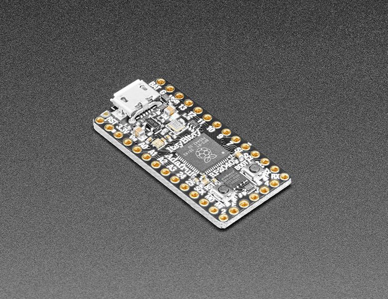
A new chip means a new ItsyBitsy, and the Raspberry Pi RP2040 is no exception. When we saw this chip we thought “this chip is going to be awesome when we give it the ItsyBitsy teensy-weensy Treatment” and so we did! This Itsy’ features the RP2040, and all niceties you know and love about the Itsy...
plucky goblet
I can plug a TinyPICO flashed with MP into the same workstation or Raspberry Pi and things work fine, so it's something with the board. It's flashing red on the LED and the rainbow is busy rainbowing.
shell badge
Try the 7 beta 0
plucky goblet
But that's CircuitPython, not MicroPython.
shell badge
It’s just to test and make sure that UF2 will load properly
You can build a uf2 for it off main on the MicroPython repo

GitHub
MicroPython - a lean and efficient Python implementation for microcontrollers and constrained systems - GitHub - micropython/micropython: MicroPython - a lean and efficient Python implementation fo...
plucky goblet
Okay, I've tried both the 6.3.0 and 7.0.0-beta.0 versions and they do slightly different things, but basically both end up with a green flashing NeoPixel.
shell badge
Circuitpy drive?
shell badge
Strange, should be circuitpy usb mass storage
plucky goblet
But when I click on it I get an Input/output error.
shell badge
Might be an issue with the flash chip.. but hard to say for sure
plucky goblet
Eew. When I actually navigate to the drive via terminal and do "ls" I get:
'¢'$'\030\002''ô'$'\001''#'$'\003''ô'               ''$'\003''╤'$'\v''I'$'\v''H■≈.U°'$'\001'
'°≈'$'\021''°'$'\b''$'$'\005''.'$'\001'\'''         'ï░'$'\021''K'$'\006''¡'$'\004''1.'$'\001''8'
'£a'$'\005''hd'                                     ''$'\022''k"hüb'$'\001''╤.3'$'\037''√'
'%.¥B'$'\017'                                       ''$'\033''k[h.ÿg'$'\006'
'0.▀■'$'\006'                                       ''$'\021''≡≥ⁿ'
''$'\006'' '$'\v''░0╜└F.pq'$'\003'                  'ñ'$'\032''.≈╜└'
'0h≤≈Θ²'$'\001'                                     'ñFI▓v▓£D.cE'$'\001'
''$'\001''0⌡τ¬p'$'\003\020''.≡╡ç'                   ''$'\025''ⁿ'$'\001''#╨"ú@.'$'\022\006''ô'
  ≈╪■.≡╜1                                           ''$'\001''ö'$'\004''¢öb'$'\002''╨.'$'\005''H²'
 1                                                  '█▓.ÖB'$'\v'
'½BΦ▌*.'$'\006''¢ß'                                 'öFzh.'$'\002''#"'
''$'\001''¿≡≈?√.2'                                  ''$'\f''≡ö·α`(i'
'≤≈*²'$'\002''.('                                   ' ≈'$'\004'' '$'\004''p'$'\020''╜.'$'\020''╡'$'\024'
Something weird going on.
shell badge
O_O
plucky goblet
It's brand new, just cut it out of the plastic bag an hour ago.
shell badge
That looks like a corrupted flash.
plucky goblet
I've got another on a robot that's fine.
Yeah, I might have to contact Adafruit tech support.
shell badge
Do you know where the flash erase uf2 is?
shell badge
It’s a file you can use to wipe the flash storage
I’m trying to hunt it down lol
Do you see a usb cdc com port?
plucky goblet
I just repeated that exercise just to confirm and it's the same every time.
You mean under /dev?
shell badge
Yeah like /Dev/tty.usbsomething
plucky goblet
No, nothing new shows up.
plucky goblet
And with the TinyPICO yes, it does.
shell badge
Or*
plucky goblet
Linux workstation, also tried a Pi.
shell badge
Okay
plucky goblet
I think you're right, bad flash makes sense.
shell badge

GitHub
Contribute to raspberrypi/pico-examples development by creating an account on GitHub.
Try building the nuke example and drag that uf2 over
plucky goblet
Okay, thanks. I'll also keep that bookmarked, would never find it otherwise.
ebon vale
Can I ask another question? haha its in regards to a new macro not showing up on the device itself
shell badge
ebon vale
Can I ask another question? haha its in regards to a new macro not showing up o...
What do you mean?
ebon vale
These two macro .py files are not showing on the rp2040 now
 shell badge
Is that from the learn guide?
ebon vale
the majority is, I copied the win illustrator just to test with a discord .py file
shell badge
Gotcha, what’s the specific error it’s giving you?
ebon vale
Just nothing
shell badge
No import error?
ebon vale
when I try to scroll to it, the others are showing, nothing else is
shell badge
Hmmm
Okay, this might be more of a circuitpython problem than rp2040 specifically
Can you post in #help-with-circuitpython with what you’ve done so far and any kind of errors or description of what happens when you try to import those files
shell badge
🙂
shell badge
plucky goblet
Okay, thanks. I'll also keep that bookmarked, would never find it otherwise.
Any luck?
plucky goblet
Just ran cmake nuke and something mysterious happened that I'm still trying to figure out...
      ► cmake flash/nuke
CMake Warning (dev) in CMakeLists.txt:
  No project() command is present.  The top-level CMakeLists.txt file must
  contain a literal, direct call to the project() command.  Add a line of
  code such as

    project(ProjectName)

  near the top of the file, but after cmake_minimum_required().
etc.
plucky goblet
Thanks. I'm guessing you can't build it from the nuke directory or its parent, must be done from project root.
shell badge
should be able to build it from flash
ah wait i found it built

Adafruit Learning System
CircuitPython for Pico will get you started in minutes!
plucky goblet
Not sure what you mean: "from flash"?
plucky goblet
Ah, another bookmark!
Okay, took a bit. I nuked it, tried flashing it with the ItsyBitsy-RP2040.uf2, that didn't work. I nuked it again and flashed it with CircuitPython 6.3.0, and now I have a CIRCUITPY drive on my desktop. I see a /dev/ttyACM0 device show up.
shell badge
good good
plucky goblet
So hardware is okay at least.
shell badge
can you get to the repl?
shell badge
minicom or screen
plucky goblet
Will need to install minicom... hold on...
shell badge
screen should be built in
plucky goblet
I'm using this on a Linux workstation but I can plug it into a Pi instead.
plucky goblet
Ubuntu 21.04 and it's not there, but I've got a Pi handy.
Hmm. Thought a Pi would have screen already but no, will install...
I'm in the REPL now.
shell badge
Okay so that’s a good sign
Put the device in boot mode and try putting the MicroPython uf2 on it
plucky goblet
Well, that's interesting. I was able to enter the REPL and clearly in CircuitPython things are fine. But if I try flashing the MicroPython uf2 it goes back to red flashing and rainbows, and no /dev/tty* mount.
shell badge
Huh
plucky goblet
yeah.
shell badge
What if you use the nuke and then MicroPython?
plucky goblet
That's what I did before but will try again.
Bootsel pops up RPI-RP2 with /INDEX.HTM and /INFO_UF2.TXT. Now will nuke...
Okay, so I've nuked twice, will now try RP.
Same, red flashing LED and rainbows. Doesn't work.
shell badge
Strange…
Maybe file an issue on MicroPython
Since it works on circuitpython it should in theory work on MicroPython
plucky goblet
I've tried v15 and then v14 and I'm currently in minicom on v14.
Just to confirm I'll try v16 again.
Okay: nuke then flash with ItsyBitsy uf2 consistently fails.
Nuke then install v16 of the pico uf2 doesn't fail, and I can enter via minicom
So the standard Pico UF2 (v16, v15 and v14) works for the ItsyBitsy RP2040 but not the current Itsy Bitsy UF2.
I'm able to turn on the LED on pin 11 using the rp2-pico-20210618-v1.16.uf2.
But if I flash it with ItsyBitsy_RP2040.uf2 I get red flashing LED and rainbows.
...and nothing shows up in /dev/tty*
So I guess I need to hunt for a different ItsyBitsy UF2 file.
I find all this rather strange because I've got an older Itsy Bitsy RP2040 on a robot and it's working just fine.
I wonder if something has changed in the production run, if the current download of the UF2 has changed (the filename is not versioned), or if this is a dud device. I think we've determined that it's not since it's able to load CircuitPython, or the rp2-pico-20210618-v1.16.uf2, just not ItsyBitsy_RP2040.uf2. So that suggests the latest download of the UF2 is awry.
shell badge
Very possible for that to be the case
 brave quiver
how do i change the led color after my code is run
currently it fades green in and out after code is done
frank quail
brave quiver
currently it fades green in and out after code is done
yep, that's how it works. If you want to keep control of the LED, you make your code not end, by ending on a loop like this for example:
while True:
  time.sleep(1)