
#help-with-hw-design
1 messages · Page 29 of 1
 tulip wedge
i was not sure if it would be able to handle a web interface and the leds
it would only be a super simple web interface tho

still needs some work
 supple pollen
Those ESP modules are really handy for builds like this
 supple pollen
Yeah, the Teensy 4 is a beast
tulip wedge
i might just cut it like this

so then i dont need headders
it will be cursed but it 'should' work
supple pollen
Yeah, Artemis style. The bottom of the board does offer additional I/O as well if you put pads in the right places https://www.pjrc.com/teensy/card10b_rev2_web.pdf
tulip wedge
i shouldnt need that
supple pollen
Yeah, you can cut it with a bandsaw, PCB shear, or milling machine with a chipbreaker bit
tulip wedge
ill just be needing to control 5 led strips and maybe a few buttons
buttons are easy tho as i can just use resistors and then analogue read so i can hook multiple up to one gpio
tulip wedge
supple pollen
Yeah, you can cut it with a bandsaw, PCB shear, or milling machine with a chipbr...
i just realised it has smd components on the back
so it wont work
oh well
supple pollen
Ouch. It should still be a pretty compact package with short headers
tulip wedge
yeah man, the regs will be taller anyway
supple pollen
AdaFruit does have a DMA NeoPixel library for the SAMD51 chips, which is another possibility
It also appears the NXP chip in the Teensy is available in a non BGA package https://www.adafruit.com/product/4950

Get ready for our fastest Metro ever - the NXP iMX RT1011 microcontroller powers this board with a 500 MHz ARM Cortex M7 processor. There's 8 MB of execute-in-place QSPI for firmware + ...
tulip wedge
ill end up adding some sort of wifi module anyway
i was thining maybe an esp8266 just to handle the web interface
tulip wedge
supple pollen
It also appears the NXP chip in the Teensy is available in a non BGA package htt...
hmmm
supple pollen
Or you might be able to use the Metro M7 and just unsolder the headers and barrel jack.
tulip wedge
i need to add voltage regs
as i was gonna power it from either a 4s lipo or 3s li ion pack
supple pollen
The Metro board can accept up to 12V in, so should work with a 3S pack.
tulip wedge
only issue is i dont think it has voltage cutout
i dont feel like killing more lipos
i already kill enough


 supple pollen
I upgraded my electric tractor with this 4kWh one
 tulip wedge
lol
hope it does not do this

i saw this when i arrived at work yesterday
it was smoking like crazy
never seen a lead acid battery smoke before
supple pollen
That's one reason I'm wary of lithium batteries in costumes
supple pollen
The lithium iron phosphate ones are safer, longer lived, and more tolerant of abuse (which is why they appeal to me)
supple pollen
The tractor had previously used lead acid
 supple pollen
They're good for that
tulip wedge
couldnt survive the tree LOL
supple pollen
Think this Arduino is okay? 
 supple pollen
Logging off soon, heading to the Gaaays in Spaaace con in Philly

 lost sky
What are these edge connectors things called that allow you to chain PCBs together

 latent jungle
[card] edge connectors
 knotty tiger
i usually think of card edge connectors as for plugging into sockets. those are more like bridging pads
tulip wedge
ok now it is good

 jade wedge
I'm planning on a project to mod an old PCjr joystick to be USB. The fact that it uses 100k pots and the board I'm using (Trinket M0) is 3.3v logic shouldn't be a problem, right? They're just voltage dividers. I know that the Trinket only has a 12bit ADC so the output is going to be coarse anyway, I'm just wondering about the pots.
(And by coarse, I mean that I'll have a total of 4096 "positions" available in total, rather than a typical joystick's 32000+ in each direction, meaning I have 1/16th the granularity)
 unique patio
jade wedge
I'm planning on a project to mod an old PCjr joystick to be USB. The fact that ...
unique patio
jade wedge
I'm planning on a project to mod an old PCjr joystick to be USB. The fact that ...
no, the resistance of the pots doesn't matter. You could use oversampling to get higher resolution. Or you could choose a different board that has a better ADC, or use an external ADC.
... BUT, just because the joystick is reporting 32k, doesn't mean that it's really 16-bit resolution. It could just be scaled. and 4k is more than the screen resolution anyway. I kind of doubt in the original application the resolution was anywhere close to 16 bits.
and the quality of the joystick pots may not be all that great to beging with
jade wedge
True on all points about the resolution. Personally I'll just be scaling up since software expects a range of -32000 to +32000. Plus it's not like this thing was going to be for precision gaming anyway.
And yeah, I've no idea if I'll get good pots anyway.
I figured the 100k pots wasn't going to be an issue, but I still wanted to check.
This is mostly "I bet could do this without looking up any guides."
unique patio
the higher the resistance, the slower the input pin is going to charge up (since it has a capacitance, though ideally it should not) when the resistance is high (so the current will be low). But 100k should be fine.
jade wedge
Fair enough. Worse comes to worse, I'll just put some 10k replacements.
Now to actually try and find one at the MIT Swapfest this weekend...
unique patio
jade wedge
Now to actually try and find one at the MIT Swapfest this weekend...
I went last fall and and bought nothing. I am at the shedding, not accumulating stage 🙂
jade wedge
Wandering and looking is what I do most times anyway. I am endlessly indecisive. Also I know I could just buy one off ebay, but this is more fun.
 coarse lark
Does anyone know a good generic relay? Im planning on making a board with relays but im not sure which one to use
 inland jungle
mechanical, solid state? for passing power, or connecting signals?
coarse lark
inland jungle
mechanical, solid state? for passing power, or connecting signals?

Havent thought of that
For current preferably since its for turning things on and off
coarse lark
unique patio
<https://www.adafruit.com/search?q=relay>
Hmhmhmhm this looks very good

I believe the featherwings also use these little white smd ones
Ill look into them
unique patio
coarse lark
Ill look into them
relays are rated by current they can pass and max voltage they can stand. Also normally-open, normally-closed, extra contacts, latching/non-latching. This is kind of asking like what screwdriver should i buy without knowing what it's for
coarse lark
unique patio
relays are rated by current they can pass and max voltage they can stand. Also n...
Yeah, you can tell im not very experienced with relays
Ill do more research
But i know i want a non latching one
SPDT
unique patio
the pimoroni and adafruit boards have relays that were chosen to be general purpose so you can start with those part selections
 coarse lark
unique patio
relays are rated by current they can pass and max voltage they can stand. Also n...
coarse lark
unique patio
relays are rated by current they can pass and max voltage they can stand. Also n...
Ok im starting to get curious, if i were ro ask you which screwdriver should i get what would be your answer
unique patio
coarse lark
Ok im starting to get curious, if i were ro ask you which screwdriver should i g...
I don't know. I'd ask you should I turn left or right at the stop sign.
coarse lark
unique patio
I don't know. I'd ask you should I turn left or right at the stop sign.
I... uh...
 coarse lark
unique patio
which resistor should i buy, anyway
coarse lark
unique patio
which resistor should i buy, anyway
The... uhh.... one with... that looks like this 
unique patio
all the same color or different colors?
coarse lark
Me brain stop werking
unique patio
lol, sorry
 cursive sentinel
coarse lark
I... uh...
cursive sentinel
coarse lark
I... uh...
 coarse lark
The adafolks are too powerful for a mere mortal like me to comprehend
unique patio
What is the difference between a duck? One leg is both the same.
Do you walk to work, or carry your lunch?
unique patio
good night, me too in not too long
Seriously though, the point is that I can't answer the question without more information.
coarse lark
unique patio
Seriously though, the point is that I can't answer the question without more inf...
Next time ill give more details when asking questions, and if someone asks me something too vague or without details i will blast them with philosophical or nonsensical questions to disturb or confuse them
unique patio
coarse lark
Next time ill give more details when asking questions, and if someone asks me so...
I apologize. I thought you were asking the screwdriver question in jest and thought I was playing along. When I answered the relay question I asked for more information.
coarse lark
unique patio
I apologize. I thought you were asking the screwdriver question in jest and thou...
nonono i was also playing with the screwdriver question no need to apologize
knotty tiger
is there a name for a single-package p-MOSFET with n-MOSFET gate driver? this would be for high-side switching 12V programming voltage with a 5V GPIO, etc, so doesn’t have to handle more than a few tens of mA. even better if the n-MOSFET can work with 3.3V gate voltage
knotty tiger
load switches are usually more complicated than what i’m looking for. maybe a discrete CMOS pair, but wired with the n-FET as a gate drive
inland jungle
not all are like that, the one I linked is literally a package with a N-fet linked to a P-fet
knotty tiger
thanks!
inland jungle
I agree, there are some with enables, and current limit setpoints, etc...
knotty tiger
i mean, a common alternative strategy i’ve seen is to use a n-FET or NPN to just pull the 12V to ground (with a current-limiting resistor of course)
inland jungle
yeah, I've seen NPN designs, the linked on uses an n-FET to pull down a p-FET gate
knotty tiger
i’m familiar with the more sophisticated soft-start load switches intended for USB device inrush limiting (the usual simple p-FET with capacitor design lets a large spike through to the load when power is initially applied)
 modest bison
posted about this project last weekend. Picked up a different panel 6v 5w, cloudy day, has kept the battery charged (at least the light is green?) all day. No deep sleep / etc.

 silk rampart
Flyback SMPS burned some resistors
tulip wedge
tulip wedge
ok now it is good
i have improved the drawing

would i need the logic converter?
unique patio
tulip wedge
would i need the logic converter?
Are the matrices something like our RGB Matrices? If so, yes, the level converter makes for more reliable operation.
tulip wedge
yep they are matixes
unique patio
ESP8266 is really old -- you might consider an ESP32 or ESP32-something
unique patio
do you already have it or you are going to buy it new?
tulip wedge
buy it new
unique patio
then spend another dollar on something with more memory, more modern software, etc
tulip wedge
ESP-12F(ESP8266MOD) Ai-Thinker $2.0314 - -90dBm 16dBm ESP8266芯片 板载PCBAntenna 2.4GHz SMD,16x24mm WiFi Modules ROHS datasheet, price, inventory C82891
tulip wedge
unique patio
then spend another dollar on something with more memory, more modern software, e...
im gonna use arduino ide there is no need
it only needs to host a webserver it is pleanty powerfull enough to do that
unique patio
At the lower level, including the software, the 8266 is more idiosyncratic. If your requirements change later...
tulip wedge
the leds will all be controlled by the teensy
the esp8266 is only to add wifi to the board
if it can run wled then it will be able to run my super simple webserver
unique patio
i understand, but Espressif doesn't recommend it anymore either
tulip wedge
i know but i dont realy care lol
it is good for my usecase
the website will look something like this but with more buttons so there is no need for more storage
 unique patio
eventually they will stop supporting it
tulip wedge
thats all good
unique patio
an ESP32-C2 or -C3 costs the sme
tulip wedge
ESP32-C3-MINI-1-N4 Espressif Systems $2.5645 - SMD,13.2x16.6mm RF Modules ROHS datasheet, price, inventory C2838502
they never have them in stock
it will be sending serial data to the teensy
the teensy will be doing all the hard work
unique patio
I am looking at LCSC, there are lot of ESP32 and ESP32xx modules in stock. We dropped ESP8266 years ago because its API was too different at the ESP-iDF level and it was too weak in so many wys
but I've said my piece
tulip wedge
i want planning to use the adafruit library on the esp8266
 worldly schooner
There have been security concerns with the esp8266 that the newer esp32 variants address IIRC
worldly schooner
Is LCSC your primary source of supply?
tulip wedge
yep
i use easy eda to design it so it just makes it so much easier to order the parts
 worldly schooner
Hm, their stock looks pretty bad, but https://www.lcsc.com/mobile/product-detail/WiFi-Modules_Espressif-Systems-ESP32-C3-MINI-1-H4_C2934569.html is a valid option
ESP32-C3-MINI-1-H4 Espressif Systems $2.5056 - -96dBm 20.5dBm 板载PCBAntenna 2.4GHz SMD,13.2x16.6mm WiFi Modules ROHS datasheet, price, inventory C2934569
If you have code written for the 8266 already then just use that
tulip wedge
i dont have any code written yet
it is just gonna be a webpage with boxes that have text on them
wyen i click on then it will send serial to the teensy
the teensy will then change the led mode based on what command it recieved
worldly schooner
And you already have the teensy?
worldly schooner
With a custom esp8266 pcb?
tulip wedge
yep!
worldly schooner
Is that actually cheaper than just a single pcb with an esp32-s2 or s3?
tulip wedge
not at all
i need to drive over 2000 leds tho
i was told that i would need to use a teensy to do that
not sure if the esp32 s2 could do that or not. if it can then ill just use that instead
unique patio
We sell this, which drives many panels nicely: https://www.adafruit.com/product/5778
Folks love our wide selection of RGB matrices and accessories for making custom colorful LED displays... and our RGB Matrix Shields and FeatherWings can be quickly soldered together to ...
out of stock right now
worldly schooner
Over 2000? What kind of LEDs?
tulip wedge
WS2812B-2020 Worldsemi $0.09 - 12mA 正贴 RGB 5V SMD,2x2mm Light Emitting Diodes (LED) ROHS datasheet, price, inventory C965555
unique patio
I thought you were driving matrices?
tulip wedge
yep
worldly schooner
How often are they updating?
tulip wedge
not verry often
tulip wedge
i was gonna make one on a custom flex pcb so it would fit the mask better
unique patio
is it a rectangular matrix, or custom layout?
tulip wedge
rectangular
unique patio
if you use addressable LED's, then it's very easy to control them, because they have memory. If you use a rectangular panel HUB75 LED, then you have to drive them continuously. So it's not an "RGB Matrix" in the usual sense. That term is usually meant for HUB75-style matrices
tulip wedge
ah ok
unique patio
For advanced NeoPixel fans, we now have a bendable, Flexible 16x16 NeoPixel LED Matrix! Control all 256 ultra-bright LEDs using a single microcontroller pin, set each LED as you wish to ...
For advanced NeoPixel fans, we how have a bendable, flexible 8x32 NeoPixel LED Matrix! Control all 256 ultra-bright LEDs using a single microcontroller pin, set each LED as you wish to ...
those are WS2812B-style (aka "NeoPixel")
 distant raven
Personally, I like the sk6812 better than the ws2812
unique patio
for WS2812B style, if they are not changing much, heavy-duty computing is not required
tulip wedge
i thought matrix refered to the shape of it
worldly schooner
There is absolutely zero requirement for a teensy with ws2812. The faster core speeds don’t help when the pixel data is fixed at 800khz. As long as you have enough memory, anything can drive the data.
unique patio
well, "RGB Matrix" is usually used for these prefab panels that can link together to make a big TV-like display etc
tulip wedge
unique patio
well, "RGB Matrix" is usually used for these prefab panels that can link togethe...
ah ok
unique patio
you are doing a NeoPixel-style display, really easy to drive
have you coded this kind of thing before?
tulip wedge
nope not at all
unique patio
what kind of programming experience do you have?
tulip wedge
ive got a little bit
worldly schooner
2000 of these things is also a lot to power. Are you sure you need that many on a fur suit?
tulip wedge
not too much tho
unique patio
sounds like you have more hw design experience
tulip wedge
worldly schooner
2000 of these things is also a lot to power. Are you sure you need that many on ...
yes
thye wont all be on at the same time
only a few will be on
like maybe 500 or so
tulip wedge
unique patio
sounds like you have more hw design experience
yeah i do
i suck a coding
worldly schooner
That is still quite a lot. Are there animations involved here too?
unique patio
were you planning to use wled? what's the inspiring project?
tulip wedge
i was not planning to use wled
worldly schooner
Are you looking to have like a 64x32 matrix of LEDs?
tulip wedge
in not 100% sure of the exact dimentions
worldly schooner
Because a hub75 might be more appropriate.
unique patio
needs to flex
tulip wedge
worldly schooner
Because a hub75 might be more appropriate.
i didnt want it to obsucre the vision like lots of other ones
worldly schooner
Adafruit doesn’t sell flexible hub75 but they do exist
unique patio
so your custom matrix has eyehole in it or something?
(see, you ask one simple question, and look what happens 🙂 )
 unique patio
oh sides of the head
tulip wedge
hense wanting a flexible pcb
 unique patio
could also control this with bluetooth or IR or buttons, if you are wearing it and just want to change things with your phone or whatever
tulip wedge
yeah i wanted to use wifi since you could set a password
unique patio
have you looked at our neopixel projects in our Learn Guides?
unique patio
search for neopixel or matrix or mask or whatever. MANY projects including wearables
use the search box in upper right
search for neopixel, matrix, mask, costume, etc. Some are old, some are new
tulip wedge
ah ok
unique patio
tulip wedge
dang the cube looks so cool
 broken zenith
I put a 10uF capacitor instead of a 10nF capacitor on an NE555's CV pin, which is pin 5. It's on a PCB that I ordered assembled (not here yet). What types of problems can I expect?
unique patio
broken zenith
I put a 10uF capacitor instead of a 10nF capacitor on an NE555's CV pin, which i...
I don't think this will be a big deal. It's a decoupling capacitor, and a datasheet I looked at sometimes just leaves that pin unconnected. Maybe you will got wonky output for a little while when power is applied.
worldly schooner
broken zenith
I put a 10uF capacitor instead of a 10nF capacitor on an NE555's CV pin, which i...
I would assume a 10uF capacitor would take 1000 times longer to charge compared to a 10nF, so your output would stay on 1000 time longer than your original design specifies.
Assuming 6 is your threshold pin, anyways?
Didn’t dig too deep into data sheets myself
Ohhhhh pin 5. Misread.
broken zenith
worldly schooner
I would assume a 10uF capacitor would take 1000 times longer to charge compared ...
I sent the wrong schematic, one sec. Using an astable circuit
worldly schooner
Yeah, what danh said. Didn’t even see that one.
broken zenith
 unique patio
I think same comment. If the output at the beginning is an issue, you could just remove it
 split obsidian
Sorry to necro-this, but I'm still struggling to pick between a TVS diode (which would require me to select an appropriate TVS diode) and the BAT54 solution. Could you weigh in on what you would use for protection on the 3.5mm jack of an adaptive switch design?
unique patio
split obsidian
Sorry to necro-this, but I'm still struggling to pick between a TVS diode (which...
i have never designed something that would need that, but I would say pick a simple integrated solution that is widely used
I'd worry about what the max voltage that the jack might see, etc
reverse polarity, etc
split obsidian
well, the jack only receives what it puts out
it's basically just an MCU pin and a GND pin. Plus whatever random static happens from a headphone jack
unique patio
I think you might need a protection diode + a polyfuse to protect the protection diode
but I mean if someone plugs in a speaker out, etc, by accident, or some other AT device that uses the same connector by coincidence
split obsidian
Hmm...I haven't seen any such protection on similar devices.
@unique patio pm'd you a photo of a pcb
cursive sentinel
split obsidian
it's basically just an MCU pin and a GND pin. Plus whatever random static happen...
BAT54 will suffice.
split obsidian
yeah?
cursive sentinel
Actually, correction: are you running audio through this?
split obsidian
we talked about this back in february. no there will be no audio, it's just a way of connecting an audio cable that's connected to a switch, tip/gnd are wired to each lead of the switch
I appreciate the diagrams you helped with
back in feb
cursive sentinel
Yeah BAT54 is fine then. A TVS would work, but as you said part selection can be a bit of a pain.
split obsidian
What about the polyfuse dan mentioned?
 jovial pelican
Maybe a longshot but I'm creating a daughter board and need to match up this connector on the mainboard: https://www.lcsc.com/product-detail/Wire-To-Board-Connector_Bossie-BX-MX1-25-2PWT_C18077932.html I know it's board-wire but is there any compatible smd male connector for this?
BX-MX1.25-2PWT Bossie $0.0253 - 1x2P 2P 1 Tin 1.25mm 2 -25℃~+85℃ 1A Brass Surface Mount,Right Angle SMD,P=1.25mm,Surface Mount,Right Angle Wire To Board Connector ROHS datasheet, price, inventory C18077932
To make a board to board connection?
split obsidian
@jovial pelican doesn't look like it from bossie itself
jovial pelican
split obsidian
<@349931215673098256> doesn't look like it from bossie itself
Agree, I've been searching around but didn't know if any other manufacturer might have a similar in male.
split obsidian
Also, do I need a resistor inline with the jack @unique patio @cursive sentinel ?
unique patio
split obsidian
Also, do I need a resistor inline with the jack <@329766224093249548> <@57880536...
The resistor does current limiting. I just found this nice overview of the whole idea of input protection: https://www.digikey.com/en/articles/protecting-inputs-in-digital-electronics
split obsidian
@unique patio oh wow, I never considered looking at remote buttons
that's exactly the article I've been unable to find
unique patio
never mind about the polyfuse, I think the resistor is probably enough
split obsidian
Long wires can act as an inductor and when a button is opened or closed, large voltage spikes can show up on the electronic paths
unique patio
I did a websearch for << input protection diodes resistors >>
split obsidian
I've been reading application notes for TVS diodes/selection, current limiting resistors, zener/shottsky diodes/blah blah.
It's been an information dump
unique patio
i agree, I sometimes find it overwhelming. Finding a seemingly high quality discussion like that is rare
split obsidian
So, @unique patio , just a resistor (what value would you put?) and would you still recommend the bat54 @cursive sentinel was recommending?
the MCU pin is using the internal pull-up resistor.
unique patio
@cursive sentinel has a lot more experience than me on this. 1k is probably fine
split obsidian
Appreciate that. I'll wait for his response I suppose. I'm just curious how a bat54s provides protection against a 8kv/15kv transient (static contact and static air-gap). I've been reading and figured that's the baseline for ESD protection testing
calculating 8kv/15kv protection for the correct TVS diode selection was proving...over my head. I'm sure it's easy enough to select one if you know what you're looking for on digikey/mouser but I just barely grasp the concept enough to start looking
cursive sentinel
split obsidian
calculating 8kv/15kv protection for the correct TVS diode selection was proving....
It really all comes down to energy. Static shocks are extremely high voltage, but generally low energy.
split obsidian
Do you happen to know the amperage those 8/15kv tests are run at?
cursive sentinel
Nope, but there are ISO standards that define it.
Either ISO or another stabdards body.
I don't think you need to worry too much about it though to be honest
split obsidian
So should I just throw some resistors on the line and not worry too much?
The example Dan sent involved 5v and 25ft of line. I'm using an rp2040 @ 3.3v and not more than 3-5ft of cable
Example meaning that article
unique patio
split obsidian
So should I just throw some resistors on the line and not worry too much?
I agree with that. someone might put an extension cable on at some point
split obsidian
So, definitely resistors. And the extension cable is an excellent point
But the tvs/bat54 is needed/unneeded if I do resistors inline?
unique patio
it's belt and suspenders (sorry for the idiom if it's not familiar). It's probably better to have them, but Adafruit rarely adds protection and we don't have a lot of people saying they've fried their inputs.
See the "External clipping diodes" section in that digikey article
split obsidian
Exactly! That's why I'm asking if it's just overkill
cursive sentinel
If you have multiple lines, I'd use a BAT54 and resistor on each. If it's just one or two, just resistors are sufficient.
You can also think of it in another way: the pair of diodes in the BAT54 are much larger than anything you will see on a microcontroller GPIO. That alone suggests that they are capable of absorbing more energy, and can withstand being continuously forward-biased (which will be the case here since you are dropping from 5 to 3.3V.
Regarding resistor values: you want something large enough to prevent excessive current from flowing from the 5 to 3.3V rail, but small enough to not severely degrade the edges of your input signal. I'd shoot for something that'll give you 1-2mA.
split obsidian
So I'm going to add 6 resistors and 6 bat54 to this project. Should I also add the capacitors as seen in that digikey article?
cursive sentinel
These are switches you are connecting to, right?
split obsidian
Yes
If you Google "ablenet switch" it's basically a micro switch soldered to a mono audio cable.
Normally open
Idk why i said basically. It's quite literally a micro switch soldered to a mono audio cable
cursive sentinel
And you're putting 5V across it why?
split obsidian
I'm not.
I suppose I'd be putting 3.3v?
It's like a keyboard switch that's on an extension
It's how the Xbox adaptive controller works
split obsidian
Why not the resistors that Dan recommended?
cursive sentinel
I mean... you can use them. But I wouldn't say it's strictly necessary.
Although you could always add resistors and capacitors for debouncing purposes.
split obsidian
Oh God. Does it matter that it's an internal pull down resistor instead of an internal pull up resistor?
cursive sentinel
For switches, you generally want a pull-up. And the internal pullups are generally too weak (many switches have a minimum current required in order to deoxidize the contacts properly).
split obsidian
Huh...
I've been using the internal pull downs successfully with my other projects
cursive sentinel
Over 5 feet of cable?
split obsidian
Probably not, but plausibly that would probably be the outer limit.
@cursive sentinel
I would assume people would use a long USB extension to the MCU vs an audio extension.
cursive sentinel
Single-ended audio cables (and jacks) are somewhat infamous for their poor signal integrity, although this is unlikely to be an issue for switches.
split obsidian
yeah, it's just the standard in the disability community, can't change that at this point
it's 3.5mm mono jacks, with some variations seen to add in TRS & TRRS & ?TRRRS? for additional switches on the same line.
but they must be backwards compatible with at least a mono jack wired switch or I'm throwing away all compatibility with all prexisting switch options
cursive sentinel
Yeah, makes sense.
And like I said, for switches it is fine. Although I must admit I'm a bit surprised they don't use something with a retention clip or latch.
 stark arch
Question 1: I am using a BGA microcontroller for my flight computer, and was initially planning to do a pwr/sig-gnd--gnd-pwr/sig 4 layer PCB to ensure everything references ground for when I switch layers. I recently placed all the components onto my board to get a better idea of how they fit together, and have become worried that the tight spacing between pinout vias and decoupling caps will negatively affect power delivery if I use a copper pour on the signal planes for power vs. a full power plane. The only thing is, parts of my board use 5V and 7.4V, so I would either have to only use a 3.3V plane and route those manually, or I could split the power plane but then I would have to route across a split power plane, which I hear isn't good. What do you think?
 stark arch
Question 2:
I am also using pyro channels in this flight computer. I have seen others use a 1 ohm resistor going into the drain in the mosfet to limit current but this would result in a large power dissipation required by the resistor at 7.4V. However, the mosfet I am using can take up to 40A and 40V, and Estes ignitors usually only draw 2-3 A, so wouldn't it just be easier to completely remove the resistors and save space and just use a wide trace going into the mosfet?
stark arch
distant raven
Sig/gnd/pwr-sig/pwr-sig/gnd/sig
wouldn't that be way more expensive tho
worldly schooner
Split power planes are fine if you can organize the different power domains into sections.
distant raven
Eh, JLCPCB has some coupons
worldly schooner
BGA design with that many pins in 4 layers can be very difficult. Which MCU are you trying to implement?
stark arch
the MIMXRT1062DVJ6B
it's a teensy based board
so I am guessing the copper pour on the bottom wouldn't work great then? I'm using less than half of the BGA pins and some of them can be wired together cus they're next to eachother
distant raven
Well, sometimes. Noise sensitive IO supply won’t necessarily like that much
On tight BGA I generally won’t do less than 6 L these days
stark arch
This is the board as it is now. I could probably directly route 5V into the regulator and directly route 7.4V into the channels and then just use a solid 3.3V plane so it would be sig/gnd-pwr/sig

if that would be an easier option
distant raven
Sometimes the cost and extra real estate for routing is worth it. And for BGA, smaller via and traces is critical for breaking out
JLCPCB allows for 0.09mm traces and spacing, 0.15mm via though that will increase the price a bit.
stark arch
.2mm vias can fit so I shouldn't need 0.15
Ig I should just try with 4 then and then if not I will try 6
distant raven
👍🏻
stark arch
stark arch
Question 2:
I am also using pyro channels in this flight computer. I have seen ...
also what did you think about^ when you get the chance
stark arch
For a buck regulator do I need a gnd plane directly below it on a 4 layer board, or is it fine if it goes sig (with buck)/pwr-gnd/sig. If it's a big deal, I could potentially move it to the other side of the board, my only worry then is that it's on the same side as multiple crystals
supple pollen
As long as the power plane is low impedance, it should be okay. Of course, the usual buck regulator design requirements still apply.
stark arch
yup, the plane should probably have a low impedance, though the pwr plane is a different voltage level than the input or output voltage and the source of the pwr plane is further away--not sure if that will affect it
 sacred badger
anyone fool with eDP? tested laptop lcd before meticulously snipping 1 section at a time and soldering to diff connector for a driver board.. upon inserting power, instantly registered as a short, power LED didnt come on, power brick protection turned on. strangely, all pins register as shorted now. Vcc to gnd, gnd to t/rxN or P, 3.3v to backlight Vcc.. hoping its a loose connector instead of i fried the darn thing. 40 pin 4 lane, color scheme sort of intuitive, going off schematics found online
cursive sentinel
sacred badger
anyone fool with eDP? tested laptop lcd before meticulously snipping 1 section a...
Well, I do validation and characterization of chips with eDP at work... so you might say that I've "fooled around" some with it 
40 pins sounds more like OLDi though; eDP doesn't map colors directly to physical pairs (the DP spec defines pixel/lane allocation for x1, x2, and x4).
sacred badger
what i meant was, blue for gnd, red for Vcc/BkLt pwr (inv pwr source on schematic?! lol ccfl days) brown and green for pairs and self test, bklt enable, hpd, etc.. i did mistakenly solder self test and bklt enable together, (schematic stated LCD Vcc En... of course i wanna enable it) and to the BLO on driver board, which is 3.3v logic, like what LCD Vcc is.. and left 3 wires disconnected, as I didnt know what they were for. after digging, looks to be eeprom? or something... 3200x1800 Sharp display from a dell latitude
 lucid dagger
lets say im a lil space-constained but want the USB cable of a thing im making to be in a certain spot- could i use two of these, connect one end to the MCU, and put the other end where i want the connector to be, and wire it up? https://www.adafruit.com/product/4396
do i have to do anything special if im just using it to move the USB connection around? is there a version that is the male connection too?

This USB Type C breakout is kinda interesting, it looks similar to our right angle USB C socket breakout, but it's an 'inline' style with pads for soldering to the connections. ...
hmm
maybe i should just make a track for the cable to go along instead
 tough matrix
lucid dagger
maybe i should just make a track for the cable to go along instead
tough matrix
lucid dagger
maybe i should just make a track for the cable to go along instead
that would probably be easier
 gritty sigil
so, here's probably a very weird idea/question, but I'd like to get your opinion on the idea. I have a project where I need to power a microphone using rj45. Yep, I said weird didn't I? So the whole idea would be something like:
microphone -> cat 5e ethernet cable -> rj45 to xlr socket metal box -> audio mixer over usb-c into a sbc.
My problem is that I need to go under a door which has just enough space to fit one of the ribbon cables for usb/hdmi from adafruit. That kind of thickness. And flat ethernet cables are obviously not thin enough, as they typically range between 1.5 mm to 3 mm thickness.
So my idea was to somehow figure out a way to use that ribbon from adafruit, but to add ethernet jacks instead. Could this even work? I know in general with ethernet, a ribbon wouldn't be possible because it would give 100 mbps max, if that, would be easily influenced by crosstalk, that kind of things. But what about my specific use case?
Also, if you have any other idea, feel free to share. And very sorry for the gigantic blob of text
to be clear here, I'm assuming that audio signal would go over the data lines of the ethernet cable, but I am not 100% sure
unique patio
gritty sigil
so, here's probably a very weird idea/question, but I'd like to get your opinion...
could you point to one of our flat cables that you mean?
These are 0.04 in (1mm): https://www.vpi.us/usf-patch-cables/cable-usf-cat6-805#idTab2
gritty sigil
sure. I was refering to this, for example:
https://www.adafruit.com/product/3562

If you're looking to make a custom cable with any two of our USB or HDMI adapters, then you'll need to have these flex cables handy! Making custom cables has never been easier. ...
supple pollen
So basically you're asking if the signal would be too negatively impacted if you transitioned from twisted pair to ribbon cable, and additionaly how to do that with 8P8C connectors?
gritty sigil
something like that. I don't even know if it is possible, I'm just exploring possibilities
this super flat cable might be the only thing that I could also use. I don't know how they found it, because no matter what keyword I used on most website, I ended up with cables that wre snake oil, didn't state their dimentions besides the length, and were misleading, promissing 40 gbps on such a thin thing
not that I care for speed in my use 😉
supple pollen
I'd guess it's possible. Presumably it's an ordinary differential microphone connector with phantom power. Since it'd differential, it's fairly noise immune, so having untwisted but nearby conductors would probably work fine for a short distance (especially if it's a low-Z microphone circuit)
Yeah, speed isn't a problem, and I doubt impedance and capacitance are particularly important, but noise immunity probably very much is.
gritty sigil
yeah it's balanced xlr connectors everywhere. The rj45 to xlr crossover box is just acting as a passthrough and changing the form factor of the rj45 into xlr from what I gathered
unique patio
what's the mic that's using an RJ-45?
supple pollen
I'd check that crossover box to see if it's a passthrough, or does transformer coupling or what, as it may be relevant
gritty sigil
it's an experimental mic from sr3d.co.uk, their garden mic bundle. I don't know if there are pictures or not given my blindness, but I can always link to it...
Alternatively I can message the owner as we're pretty good friends, and he might be able to answer me more precisely
but yeah this ultra thin cable I was linked to, it does seem promising, if I could get my hands on one of them somehow. Sure less hackish than trying and finding a way of making what amounts to a custom connector for the ribbon from adafruit
unique patio
I looked at all of sr3d's products, and they are all XLR, USB, or phone jack, it appears. So you have something new.
do they need phantom power?
gritty sigil
right. The garden stream bundle product page only briefly mentions the rj45 to xlr sockets crossover box. I'll see about contacting him directly to ask more details on it.
Yes, they do need phantom power -- I own another dummy head for moving about and recording on different location and can at least definitely confirm that
unique patio
https://www.monoprice.com/product?p_id=42158 is 0.4mm self-adhesive four-conductor wire, meant for speakers, but might be easier to work with. There are connector blocks further down the page.
I guess you cannot make a hole in the wall 😄
ugh. too bad. The connector blocks are no longer sold
gritty sigil
heh :/ I live there but I don't own the place, not to mention the wall is concrete :p
unique patio
OK. Here is the same stuff, sold on Amazon, with two and four conductor wire, and also connector blocks:
https://www.amazon.com/stores/page/F091E79B-EBBE-4661-9AA3-C26781093163
"Sewell Ghost Wire" is the brand name.
gritty sigil
that 0.04 thickness seems to be in inches so that would be about 1 mm thick, I reckon? That ultra flat cable that was first shared, I mean
unique patio
yes, it was given in inches. Very slightly over 1mm. That was just what I found with a quick search. "Super flat" seems to be a term.
gritty sigil
yeah I don't know the exact dimentions that fit... I know the adafruit cable does. I suppose I could always try that 1 mm cable as a test, see if I can even close the door fully with this or not
unique patio
you are trying to run it under the door? Is there some seal at the bottom of the door? Usually there is a small gap so it won't drag
gritty sigil
yeah there is, but it must be very very small because all I could seem to fit there was the ribbon cable I got
I couldn't say exactly how big the gap is, but yep it's tiny
unique patio
is it carpet or hard floor?
it could be a rubber molding that is mashable
is this from outside to inside, or it's an inside door.
gritty sigil
the door has a rather large bump from the floor, because there is a tiny step you must go over to cross the door, and that is all part of the frame. It's a bay window glass door (not the sliding kind, the ones that open literally like a door as you pull on it)
unique patio
ah ok, so it has a weather seal or something. Did you try placing the slightly thicker RJ45 cables you have on the threshold and closing the door?
gritty sigil
well I only have the regular, round shaped cables for now. Those definitely get the heck squeezed out of them on top of preventing the door from closing, as expected
unique patio
That I can believe. But if you could just try something that's 1.5 to 2 mm thick, like cardboard or a ruler or something, that might be enlightening. you might not be able to stick it underneath but you could see if it closes without too much squeezing.
gritty sigil
the alternative is to get the usb version, which I'm definitely still keeping in mind. But I'm mostly curious by now if I could even get that working, kind of challenge
unique patio
but there also might be some 90-degree lips that are going to damage any cable. Are there any nearby windows that slide up and down or something, that you could not close all the way and insert foam to fill the gaps?
gritty sigil
nah even the windows use this same idea of a gap plus weather sceal, and they all open like doors too
I figure out that I can also put it on the side, rather than going outside from under. That is, if I grab the ribbon I've got, then tape it to the thick window pane of that bay window so that it remains wrapped around it, then in theory I should avoid any nasty angles or such. The spacing between the frame and the door is the same, from under or going at it from the side
unique patio
is it a double door?
gritty sigil
no it's more like huh. A giant pane of glass that takes half of a wall or something, with a door to the extreme right of it
unique patio
got it. good luck. I have had to get antenna wires through windows and walls, similar issues
gritty sigil
sorry if it is hard to understand. I'm really not that good at describing things, since I mostly work them out by touch, and I know enough to know by now that sometimes touch doesn't reflect sight
unique patio
i would suggest Bluetooth or wireless audio, but sounds like you are very concerned with fidelity
gritty sigil
haha yes I'm actually doing that both for a fun project to work on, and for my own use for relaxing. Nothing like having a 3d audio of the rain raging outside while you're resting, and knowing it is your own project that brought that to you, I reckon.
I guess for sighted folks it would be the difference between using a cheap camera or a high-end one to capture what they like to enjoy the most.
unique patio
sounds great!
gritty sigil
yeah I got all over this project more than a year ago and I've been trying to figure out how to make it work. So far I think the easiest way I found is to use the adafruit ribbon with usb, and to use self-amalgamating tape to waterproof all of the usb connections
the rj45+xlr version was mostly an interesting idea because I do have an xlr audio mixer 😉
unique patio
I just looked and found audio wireless transmitters that claim they stream non-compressed audio at high bit rates, e.g. https://www.amazon.com/1Mii-Wireless-Transmitter-Receiver-Subwoofer/dp/B09MCGQ8S2
also found a bunch of wireless XLR transmitter/receiver pairs on amazon as well
gritty sigil
thanks so much ! This is all things I'll have to consider carefully, I really appreciate the help by the way
unique patio
You're welcome!
gritty sigil
thought experiments are always fun, I find
 white spear
Hi. Can someone help me out pls. I found this USB 3.0 to EMMC design circuit from github. I wonder if the data lines are correctly connected (?). The designer divided the data lines in x4 mode. Would this circuit work?
 supple pollen
That pinout looks wrong (for example pin 39 should be S1CK_M1D0 but that diagram shows it as unconnected).
Are you trying to fab a board from this design, or lay out your own board or what?
white spear
im making it as a project
and order it already assembled from a pcb fab like jlc or something
supple pollen
USB 3 is pretty demanding, you need impedance controlled traces and the like.
white spear
yeah.... on the data lines and on the USB dif pair
supple pollen
 white spear
thats the IC, but from what ive been reading. The software needed to flash the NORFLASH its only found in chinese and russian websites... maybe it's better if i switch to a simple USB 2.0 and use the RTS5170
supple pollen
As I said, the pinout there doesn't match the pinout on the schematic, which is worrisome. In general, I would opt for a better documented chip (ideally one with software for a modern OS) and the more forgiving USB 2.
white spear
yeah i 100% agree! Ty for ur help 😁
 spice zenith
Just confirming before I hook one up and damage it. The USB pin on a Feather ESP32-S3 (3rd from the li-poly connector) is connected to the VBUS line on the schematic found on the Learn page, correct? Meaning I can power the device by applying +5V to that pin from a suitable power supply.
TL;DR I'm building a fairly large NeoPixel display, and using a couple of 75W 20V to 5V buck converters to power the whole thing. I'm using the standard 3 pin JST connectors to hook up the NeoPixel strips, and it makes a huge amount of sense to just feed power back into the Feather down that cable, rather than having to faff around with a separate USB wall wart, and the additional cabling to get that connected to the Feather.
sacred badger
ayo, i was today years old when i learnt these eDP cables utilize what is referred to as MICRO COAXIAL wires -- splains that metal bar I seen in the connector, gnding all the shielding together, and splains why all the wires are shorted to gnd. LCD isn't fried after all
tough matrix
spice zenith
Just confirming before I hook one up and damage it. The USB pin on a Feather ES...
Yes, even though the learn guide says that this is not supported, this should work; I have done such setups before.
One warning: you can connect 5v to VBUS or you can power through USB port, but you should never do both at the same time. Otherwise, the 5v power you connect to VBUS will be directly connected to USB pin, which may result in your 5v source feeding power to the USB device (computer?), which is not recommended.
unique patio
spice zenith
Just confirming before I hook one up and damage it. The USB pin on a Feather ES...
right, not recommended (see last paragraph on https://learn.adafruit.com/adafruit-esp32-s3-feather/power-management) because of the danger of backpowering your computer's USB port if you forget to turn off the external 5V power.
white spear
Hi. I need help chosing a mosfet. I got a 3.3v @200mA power rail but it's not powerful enough. I need a mosfet that takes that input and switch the mosfet on so i can use the other 3.3v @1A power rail to power stuff. It's basicly a 3.3v switch. I'm making the PCB with assembly on the JLCPCB so i want to keep the costs low as its just a project and use the max Basic parts i can. I choose the AO304. Would this work? or any on this list?

 tough matrix
unique patio
right, not recommended (see last paragraph on <https://learn.adafruit.com/adafru...
tough matrix
unique patio
right, not recommended (see last paragraph on <https://learn.adafruit.com/adafru...
BTW, I always wondered.
It would be easy to avoid this problem if the VBUS pin were connected after the diode (D4 in this schematics):

is there a reason why it is not done so? The only drawback I see is that then Vbus voltage would be (5v- diode volatge drop) - is this why it was not done?
spice zenith
tough matrix
Yes, even though the learn guide says that this is not supported, this should wo...
@danh That's definitely not going to be an issue. The whole reason I want to power the Feather via the "three pin jst NeoPixel connector" is because, as I noted, I explicitly plan not to have USB power available.
unique patio
tough matrix
BTW, I always wondered.
It would be easy to avoid this problem if the VBUS pin ...
I am not sure but I believe the reason might be to prevent a further voltage drop when FeatherWings get powered like this: https://learn.adafruit.com/adafruit-feather/feather-specification#vbat-and-vbus-usage-on-wings-2861841. The Feather was really designed for use with LiPo batteries. If you want to power it with 5v you can do so through the USB jack.
stark arch
Hello, for my pyro channel I've seen others use a 1 ohm resistor into their drain to limit current. Although a few 1W resistors should theoretically be fine if the gate is only closed for a short period of time, I was wondering if it would just make more sense to completely remove them. The mosfet has a max voltage of 40V and max current of 40A, and the max voltage that would theoretically be sent through would be 8.4V (from a LiPo). Wouldn't it just save space and be easier to just get rid of the resistors in this case?
 worldly schooner
stark arch
Hello, for my pyro channel I've seen others use a 1 ohm resistor into their drai...
worldly schooner
stark arch
Hello, for my pyro channel I've seen others use a 1 ohm resistor into their drai...
I’d probably recommend doing a bit more math just to be safe, as the mosfet ratings are typically what it can safely carry, not an absolute limit.
stark arch
well 8.4V is well within that threshold is it not? Or am I missing something
knotty tiger
stark arch
well 8.4V is well within that threshold is it not? Or am I missing something
it’s more complicated than that. typically that current max is assuming certain ideal conditions. there’s also a Tj (thermal, junction temperature) limit, and for a power MOSFET they typically give you enough model parameters to help you calculate the actual thermal limit for your use case
stark arch
Ok so I did a little looking into calculations based off of what you said. To calculate power dissipation, I used R_DS_ON*I^2. The resistance of the pyro charge will be around .7ohms, and should only require 2-4A to ignite, so the current draw shouldn't be more than that. Using the above equation, it would be 4^2 x .0007 = 0.0112W, which is well below the max power dissipation, 34W. Given the diagram (from the datasheet: https://www.mouser.com/datasheet/2/196/Infineon_BSZ063N04LS6_DataSheet_v02_01_EN-3360873.pdf) and the fact that the gate will only be closed for a short period, the temperature of the mosfet shouldn't change enough for it to reach the max temperature. Is that reasoning correct?
 knotty tiger
stark arch
Ok so I did a little looking into calculations based off of what you said. To ca...
knotty tiger
stark arch
Ok so I did a little looking into calculations based off of what you said. To ca...
what happens if the charge (or the wiring to it) is shorted?
note you can estimate or measure the internal resistance of the LiPo, likewise for the wiring (though maybe account for worst-case situations like a short as close as possible to the FET given the wiring and connector situation)
knotty tiger
stark arch
Ok so I did a little looking into calculations based off of what you said. To ca...
are you using a high enough gate voltage to achieve the specific Rds(on)?
stark arch
knotty tiger
are you using a high enough gate voltage to achieve the specific Rds(on)?
Yup
knotty tiger
temperature rise will depend on thermal resistance to ambient, which the datasheet provides for a specific mounting configuration. for other situations, you’ll need the junction-to-case thermal resistance, plus that of your heat sink
stark arch
It’ll be 3.3V which is above the gate threshold
stark arch
knotty tiger
what happens if the charge (or the wiring to it) is shorted?
You make a good point there though- might be better to keep the resistors there then just in case
knotty tiger
stark arch
It’ll be 3.3V which is above the gate threshold
threshold isn’t the same as Vgs for minimum Rds(on). the datasheet says 8.8mOhm max at Vgs=4.5V
looking at Diagram 8, Rds(on) shoots up very quickly below Vgs=3.5V
stark arch
So if vgs is 3.3v it looks like rds on might be too high-might need to use a different mosfet then
Thanks for pointing that out
knotty tiger
stark arch
So if vgs is 3.3v it looks like rds on might be too high-might need to use a dif...
this looks like some useful advice about choosing power FETs to be driven by 3.3V logic
https://electronics.stackexchange.com/questions/106425/mosfet-and-3-v-power-supply

Electrical Engineering Stack Exchange
I want to control an N-channel MOSFET from a 3 V power source.
The thing is, I have difficulties understanding how to know the minimum Vgs value is to be applied for the MOSFET to be saturate...
inland jungle
yeah, there are 'logic-level' mosfets that do pretty well with a Vgs of 3.3V, especially if you're not trying to drive them at high frequencies
sacred badger
is it safe to assume a dell laptop's keyboard matrix table is stored in the bios
stark arch
ok, so I did some research on another potential mosfet. this one seems promising: https://www.mouser.com/datasheet/2/196/Infineon_BSZ0902NSI_DataSheet_v02_03_EN-3360859.pdf
Looking at diagram 7, it seems that 3.3V will be well within the Vgs needed to accomplish what I need to. Looking at diagram 6, at around 8V (which is the max it should be with 1 ohm resistors in front of it) the RDS (on) will be about 2.3-2.4 mOhms. Calculating it using the previous equation, power dissapation should be at max 8.4^2*.00024=.0169W, which is well within the max power dissipation (48W). Using Rθja x Pd _+ Tamb=Tj to find temperature rise, .0169 x 50 + 24 = 24.845--nothing it shouldn't be able to handle. This might be a little higher if I include switching power losses, but I'm not sure what I should use for switching frequency because it will only be on for a short period and then off indefinitely. Also, the Rθja is with a 6cm^2 cooling area, does that just mean nothing is within a 6m^2 area of the component? Is my logic here correct or am I missing something again?
knotty tiger
stark arch
ok, so I did some research on another potential mosfet. this one seems promising...
i think that means 6cm^2 of copper soldered to the die drain pads (see note (2) under thermal characteristics)
knotty tiger
stark arch
ok, so I did some research on another potential mosfet. this one seems promising...
in Diagram 6, the 8V label on the curve is the Vgs, which you're not going to get with 3.3V logic driving it
stark arch
My bad- linked the incorrecct datasheet. This is the one i'm talking about: https://www.mouser.com/datasheet/2/196/Infineon_BSZ0902NSI_DataSheet_v02_03_EN-3360859.pdf
knotty tiger
ah, but at 3.2V Vgs, there's about 4.3mOhm at 5A, so you're probably good
stark arch
they are really similar but that one graph is slightly different, looks like with a 3,3V Vgs Rds (on) will be 4 mOhms about
I apoligize for that mistake on my part
wait those are the same datasheets--sorry I'm going crazy
knotty tiger
the 40V FET you linked earlier is not nearly as suitable with a 3.3V Vgs
stark arch
yup so this one is much better then? My other slight concern would be if I am not using the 6cm^2 copper are that they are using. I found this equation online to calculate the Rθja and this would get it to be 2.625 K/W. This is using Tj max as 150 C, Ta as 24C, and the max power dissipation as 48 W. I assume the issue here is that the max collector power dissipation (PC max) is not the max mosfet power dissipation? Though I'm not sure how much of an issue it will be given how short of a time the mosfet will be on


 strange ibex
Hi! I'm trying to design a circuit, that needs for some of the components 5v power. The end user provides their own power for VIN, and VIN needs to support anywhere from exactly 5v to 8v. If the user plugs in 8v, that's easy I can regulate it down to 5v. However, I'm trying to decide what the best strategy would be if exactly 5v is provided on VIN. Something like an LDO is out, as 5v in and 5v out is outside what that's meant for. What strategy would you folks recommend? I want to keep it simple if I can.
sacred badger
Require higher than 5v
 pliant flame
I'm curious about designing my own PCB, but I have absolutely no idea where to start. My goal is to create a featherwing: with two headers that will connect my sensor via i2c, power, ground and a button that will connect to 2 positions on the header when pressed. What pcb software should I use and is there a blank featherwing pcb board file that I can start with?
tough matrix
pliant flame
I'm curious about designing my own PCB, but I have absolutely no idea where to s...
among the free PCB design software options, KiCad is the most widely used (but not the only one). It is not too hard to start using, though I wouldn't say it quite easy, but I'd start with it anyways. There are tons of tutorials on https://www.kicad.org/help/learning-resources/
and if you have questions, people in this channel will be happy to help you
Community created resources to learn KiCad
As for featherwing templates, there are general featherwing design principles here: https://learn.adafruit.com/adafruit-feather/feather-specification
I do not have a ready KiCad fetahering sample design, but I am sure googling will turn out quite a few
tough matrix
Actually, KiCad contains footprint for blank Feather board out of the box:
 pliant flame
When creating a pcb to isolate i2c and vcc, are the pcb layers separated or can I use one layer and the isolating chip will take care of the isolation? I'm attempting to wrap my head around all this. This is beyond my comfort level 😂
 woven bluff
you want isolated power just for I2C? sounds like overkill.
do you have a rail just to power I2C bus? if not, you'll need an isolated DC-DC module, to power the secondary side of the isolation chip.
cursive sentinel
pliant flame
When creating a pcb to isolate i2c and vcc, are the pcb layers separated or can ...
Yeah, I agree with @woven bluff. I'd need to know more about the use case in order to determine whether isolation is even needed.
woven bluff
also I2C is bidirectional, the isolation chip need clock sync
best just route I2C bus away from nosiy part of the PCB, you'll be fine
pliant flame
I plan to have ec and ph water sensors . Im reading noise from water pumps and etc can cause interference so using i2c isolation can lessen the noise
pliant flame
woven bluff
do you have a rail just to power I2C bus? if not, you'll need an isolated DC-DC ...
I want to isolate the i2c signal, sorry for the lack of explanation. I was assuming with i2c isolation I would need to isolate the vcc, and ground as well.
woven bluff
i2c is digital, vcc noise cannot harm it as long as its properly decoupled
cursive sentinel
Regardless, trying to run I2C with galvanic isolation is going to be a pain (and somewhat expensive). It would likely involve a pair of PCA9615 chips (one on each side). However, since the PCA9615 doesn't provide DC balancing, you can't capacitively couple the differential pairs directly.
cursive sentinel
woven bluff
i2c is digital, vcc noise cannot harm it as long as its properly decoupled
Not entirely true, especially if there are supply variations at one end of the bus but not the other.
Also, as a general rule you can't trust digital circuits to behave properly in brown-out conditions.
However, in this case, you can likely still get away with using the PCA9615 (without galvanic isolation).
pliant flame
I was reading through the sensors documentation and came across this.
 woven bluff
cursive sentinel
Not entirely true, especially if there are supply variations at one end of the b...
woven bluff
cursive sentinel
Not entirely true, especially if there are supply variations at one end of the b...
nothing simple can protect against large surge and brown-outs, I'd focus on filtering the pump supply rail
this is bull...
 cursive sentinel
pliant flame
I was reading through the sensors documentation and came across this.
cursive sentinel
pliant flame
I was reading through the sensors documentation and came across this.
Ok, that'll work. It's a dedicated I2C isolator.
Regarding your original question: yes, you can use the same layer. But I do recommended making it clear where the isolation occurs.
woven bluff
I2C is not the only system that can be affect by the water pump, motors are nasty, especially brushed ones. the power rail need proper filtration and the motor driving part away from the digital part of the PCB
cursive sentinel
Oh, yeah. Motors should always have their own (dedicated) rail.
pliant flame

Sometimes you'll find yourself with an I2C bus controller on one side, and an I2C bus device on the other and you gotta keep em (electrically) separated. Maybe because one is ...
cursive sentinel
If you can provide two isolated supplies, yes.
pliant flame
By supplies, I'm assuming two separate vcc supplies? Can I use vcc from the feather PCB and split it to make two separate supplies?
woven bluff
no, you cannot "split" it, the two rails must be galvanically isolated, ie. transformers
supple pollen
pliant flame
By supplies, I'm assuming two separate vcc supplies? Can I use vcc from the feat...
Or an isolated converter chip such as ADUM5000
pliant flame
@supple pollen I was looking at an ADM3260 which has both i2c and power isolation in one package
I have absolutely no idea where to start. I have kicad installed and pulled in the featherwing footprint. That is as far as I've got since lastnight 😂
I may look on youtube and the links mentioned before on how to create a basic pcb of some sort. Hopefully that will get me going with creating schematics and a pcb
tough matrix
pliant flame
I have absolutely no idea where to start. I have kicad installed and pulled in ...
before doing the feathering, do a simple board with something like 1 led, 1 resistor, header pins.
workflow is:
- create project
- edit schematics, add elements
- annotate the schematics and assign footprints for each element
- switch to PCB editor, update from schematics, place the components, draw traces
pliant flame
@tough matrix I'm working on this at the moment:
 supple pollen
Ah yes, the Kicad tutorial. I started with that too, not long ago. Here's where I am now.

This board is deliberately laid out oddly
inland jungle
do you have much experience 'hardening' circuits for industrial deployment? Is it galvanic isolation everywhere?
pliant flame
@supple pollen that looks complicated, but I'm sure it probably wasn't with some practice and know how. How long did that take you to layout in kicad?
inland jungle
that was madbodger. I'm a KiCad novice/Eagle refugee
pliant flame
oops 🙂
distant raven
inland jungle
that was madbodger. I'm a KiCad novice/Eagle refugee
I’m also an Eagle refugee. It’s been a rough transition but I’m figuring it out
 fervent lance
I dunno with other edas but kicad struggles a lot with big projects, it endlessly freezes
supple pollen
I too am an Eagle refugee, so I had some experience to draw on, just learning how to do what I want in Kicad. Not sure how long total, because like most projects, I'll work on it for a bit, then pick it up again a few days later.
tough matrix
fervent lance
I dunno with other edas but kicad struggles a lot with big projects, it endlessl...
how big are the projects where it freezes for you? in number of components?
tough matrix
distant raven
I’m also an Eagle refugee. It’s been a rough transition but I’m figuring it out
I switched about a year and a half ago and never looked back
inland jungle
I have access to Fusion360 for pcb layout, but I haven't really tried it yet
latent jungle
fervent lance
I dunno with other edas but kicad struggles a lot with big projects, it endlessl...
That has never been my experience. If it is in PCB, then disable auto-fill for zones.
 stark root
Does anyone know how the USB C maps? I can't find anything on the interwebs...
I want to enable the 5V on the USB C within my code if possible.
 inland jungle
pretty sure you can't source 5V out of the USB
stark root
If I needed 5V, you think breakout cable? for rugged-ness I'd like to avoid hacked cables as much as possible.
inland jungle
Where's the source of the 5V, battery pack?
stark root
inland jungle
Where's the source of the 5V, battery pack?
yes
inland jungle
then you'll probably want some sort of Y-cable splitter to let you plug the batter into the board and give you another connector to use
 surreal tangle
stark root
Does anyone know how the USB C maps? I can't find anything on the interwebs...
...
surreal tangle
stark root
Does anyone know how the USB C maps? I can't find anything on the interwebs...
...
The boost converter powers the USB type A socket, not the type C connector. So if you need to connect a USB type C cable, you could use a USB A to C adapter. It looks like you enabled the boost converter via IO18.
 stark root
surreal tangle
The boost converter powers the USB type A socket, not the type C connector. So...
stark root
surreal tangle
The boost converter powers the USB type A socket, not the type C connector. So...
I need to use both USB A and C, and need them both powered... I'm thinking I'll have to break out USB C and power off ext. Vbat
 vague sigil
inland jungle
pretty sure you can't source 5V out of the USB
vague sigil
inland jungle
pretty sure you can't source 5V out of the USB
I thought that the USB pin was the 5v power from the USB port...
https://learn.adafruit.com/adafruit-feather-rp2040-pico/pinouts
"USB - This is the positive voltage to/from the USB C jack, if USB is connected."
 inland jungle
the Vbus pin? Yeah it will show 5V from the USB when connected, and if you apply 5V to it, it will show up at the USB port, but there is a diode blocking the voltage from the battery from showing up at that pin and the USB port. If you jumper from the Vbat to Vbus, and bypass the diode, then I suppose you can get voltage on the USB from the battery, but you risk damaging whatever you might plug into that port while the battery is attached. The protection diode is there for a reason. If you want to take that risk, you can bypass the diode.
vague sigil
Why not just attach a wire to Vbat then....
 crimson grove
stark root
Does anyone know how the USB C maps? I can't find anything on the interwebs...
...
crimson grove
stark root
Does anyone know how the USB C maps? I can't find anything on the interwebs...
...
I've got a similar question. I'm filling up my shopping cart with components to buy from Adafruit, and I'm trying to figure out if I can use the USB-C port in host mode to connect a keyboard, with power supply coming from a battery (LiPoly Charger BFF Add-On for QT Py) .
I'm considering the QT Py RP2040, and I found the user manual that mentions jumpering the USB 5v pin to the breakout 5v pin.
I feel silly for asking, but I'm new to this, so I'll ask. If I solder that jumper, would I still be able to use the USB-C port to power a keyboard and plug in the QT PY to a computer for code updates? (not simultaneously of course)
 crimson grove
I've got a similar question. I'm filling up my shopping cart with components to ...
crimson grove
crimson grove
I've got a similar question. I'm filling up my shopping cart with components to ...
I also noticed this in the manual:
Note that you cannot power the USB port by supplying 5V to
this pin: there is a protection diode that prevents the 5V from reaching the USB
connector (unless you bridge the jumper on the back!). This is to protect host
computer USB ports, etc.
Does this mean there's a danger to connecting to my computer after bridging the jumper? Let's say I forget to turn the battery power switch off, and I plug in, supplying 5v power to my computer's usb, would that somehow damage it?
supple pollen
crimson grove
I've got a similar question. I'm filling up my shopping cart with components to ...
Yes, it will still work both ways if you bridge that jumper. All it does is disable the one-way diode that keeps power from flowing from the 5V pin to the USB connector, so with the jumper closed, power can flow either way.
The BFF contains its own diode, so if you have a BFF connected in, with a LiPo cell plugged in, and the BFF switched on, it still won't try to route 5V to your LiPo cell.
stark root
For my application, I broke out the USB C cable into flying leads, spliced in a clean 5V to the peripheral I am using and it did not work.
supple pollen
Hmm, that seems like it should work, but maybe there's something about your setup I don't understand
crimson grove
supple pollen
Yes, it will still work both ways if you bridge that jumper. All it does is dis...
Thank you!
 livid sand
how do i import a gerber file into easyeda?
 drowsy drift
livid sand
how do i import a gerber file into easyeda?
drowsy drift
livid sand
how do i import a gerber file into easyeda?
I'm pretty sure you cannot. Gerbers are an output format, not a design format.
 minor flax
just two quick questions, did I commit any sins and how to I add more LEDs without causing them to dim too much? This is an astable 555 with a fade in fade out led, vcc is a lithium cell at 3.7v

also sorry the leds are rated at 3.7V 20mA I was using a 220 on there but I'm not sure if that's right
cursive sentinel
Most "modern" LEDs don't require 20mA, but their max current rating is often just under that. 5-8mA will usually give you sufficient brightness. As far as selecting a resistor is concerned, the voltage drop depends primarily on the color. As far as LEDs are concerned: how many do you want to add?
Oh, one other thing: you may run into issues using a 1000uF cap. I'd recommend switching it to 100uF and changing the resistor to 1MOhm.
minor flax
They're UV leds so maybe the 20mA matters, but like 3 or 4 total maybe a few more, I just don't really understand how to calculate the appropriate resistance for adding more
knotty tiger
minor flax
They're UV leds so maybe the 20mA matters, but like 3 or 4 total maybe a few mor...
when connecting LEDs in parallel, it’s best to give each one its own series resistor, so they share the current equally
minor flax
you're saying like option b right but I what I dont' understand is how C is 33ohms and and b use 120

Oh duh because they're resistors in parallel ok gotcha so for every led I add I'll have to adjust all the resistors to match
Okay I got it now so I would use 35 ohms each thank you kind strangers
knotty tiger
minor flax
you're saying like option b right but I what I dont' understand is how C is 33oh...
options A and B are equivalent for most purposes
minor flax
yeah I just mean I couldn't figure out why the resistor values are so different until I realized that the resistance is about the same
knotty tiger
35 ohms each is too much current for your case
minor flax
is it? should be about 20ma no?
knotty tiger
minor flax
is it? should be about 20ma no?
no, with the 6V battery, you have (6-3.7)/120=19mA each for options A and B
minor flax
oh no I have 3.7v
knotty tiger
each parallel branch has 6V across it (assuming ideal wiring)
minor flax
the options picture was just an example I pulled off the net
knotty tiger
oh, so what’s the forward voltage of your LEDs?
minor flax
3
knotty tiger
ah, 35 ohms seems about right, then. keep in mind a fresh battery will have higher voltage
minor flax
awesome thank you so much
knotty tiger
other than 35 ohms not being a standard 5% value, but you could round up to 36, which is
minor flax
Yeah I'll see what they have at the store, no worries
cursive sentinel
Option C will result in most of the LEDs not even lighting up.
vague sigil
For the future: if you're going to drive high power LEDs or something that will heat up, look at a constant current LED driver. Sparkfun sells one. They are considered the "proper" way to power high power LEDs, but the input voltage needs to be higher than the sum of all the forward voltages, which can get.... excessive.. Very quickly
cursive sentinel
Yep, constant current is the way to go especially if you want consistent brightness across multiple LEDs.
inland jungle
you can get multichannel constant current driver chips for not that much
TI’s TLC5916 is a 8-bit constant-current LED sink driver. Find parameters, ordering and quality information
minor flax
vague sigil
For the future: if you're going to drive high power LEDs or something that will ...
oh yeah that would be a lot of voltage, am I fine here as is or 😬
vague sigil
You can do whatever you want for personal projects, and for the small LEDs it makes no difference
Do not confuse "proper design for high quality products" with "I just want to do this project for fun"
 torpid trout
A very basic question: I wanted a simple way to measure capacitance from a microcontroller. It seemed like the naive version would be to just use a dc voltage across a pair of series capacitors (one known) and measure the voltage (e.g. https://tinyurl.com/262buyou) but most of the actual circuits I see seem to use an RC filter with a peak detector, which seems a bit more elaborate. What is the issue with the naive approach?
knotty tiger
torpid trout
A very basic question: I wanted a simple way to measure capacitance from a micro...
practical capacitors have parasitic inductance and resistance that means they won't share voltage in direct proportion to their capacitance, especially if they have different types of construction
capacitive voltage dividers do exist, but they're usually used with AC or high-voltage DC, and they're made with capacitors of known value and similar construction
torpid trout
Makes sense, thanks. (This repo got my head scratching, perhaps it sort of works for certain types of capacitors, as you indicated.) https://github.com/codewrite/arduino-capacitor
knotty tiger
torpid trout
Makes sense, thanks. (This repo got my head scratching, perhaps it sort of work...
yeah, that's using a model that includes the pullup resistance and stray capacitance. it might be workable, with some manual calibration
for an extreme high-voltage example of capacitive dividers, see https://en.wikipedia.org/wiki/Corona_ring#Grading_rings

A corona ring, more correctly referred to as an anti-corona ring, is a toroid of conductive material, usually metal, which is attached to a terminal or other irregular hardware piece of high voltage equipment. The purpose of the corona ring is to distribute the electric field gradient and lower its maximum values below the corona threshold, prev...
torpid trout
It seemed like the effect of leakage current (resistance) of the capacitor might, especially if the equivalent resistance is quite large, be somewhat mitigated by taking the measurement right after the dc voltage is applied. It's an intriguing idea, and (in my case) mostly looking for changes in an unknown, small capacitance. I tried a few experiments and it seemed to work for capacitances that were relatively similar to each other across the divider; though I don't think I've tried using very different types of capacitors.
knotty tiger
torpid trout
It seemed like the effect of leakage current (resistance) of the capacitor might...
i think most practical capacitance measurements use a modified Wheatstone bridge that runs with AC, and incorporates both known capacitance and resistance legs (also can give you ESR of the unknown capacitor, i think)
torpid trout
ack. ( Mostly curious about issues with the alternate idea, and what you noted earlier makes sense.)
 ocean coyote
does anyone know of a 5 pin usb c port that acts as a drop in replacement for a microusb port?
im guessing they dont exist because of the extra resistors needed? and maybe the way the pins are laid out sucks.
or even a 4 pin one that could be adapted to work? cuz the extra pin is for OTG IIRC
ocean coyote
also if im using the pico as the device and the piousb as a host can i usb the bus power from the device or should i be powering it separately
 supple pollen
torpid trout
It seemed like the effect of leakage current (resistance) of the capacitor might...
supple pollen
torpid trout
It seemed like the effect of leakage current (resistance) of the capacitor might...
As with series electrolytics, you can mitigate that with balancing resistors that swamp the leakage with a larger, known leakage. A possible side advantage is that you have effectively paralleled a resistive divider with a capacitive ones, giving useful response at DC as well. The obvious disadvantage is the need for precision high value (and generally, high voltage) resistors.
torpid trout
supple pollen
As with series electrolytics, you can mitigate that with balancing resistors tha...
Ah, I see - that's a neat idea! Nice, thank you for the tip.
 small sapphire
https://www.adafruit.com/product/4090
hello, im planning to work on a project with a pi pico that i want to use usb c with. i saw this breakout board but im a little confused about the naming. if im not mistaken, a downstream port belongs to a host (?) but the backside of this board says (periph.) does this mean that i can use this board with a pico as a device connected to a pc?

Throw out all those Mini and Micro B USB cables you have in a plastic bin - the next generation of USB connectors is here with USB C! You will start to see these connectors pop up on all ...
thanks in advance :)
knotty tiger
small sapphire
https://www.adafruit.com/product/4090
hello, im planning to work on a project w...
the CC resistor values mean it’s for an upstream-facing port, and the text implies “downstream” in the title means which end of the cable it’s on. (the USB specs say “upstream-facing port” in an attempt to decrease ambiguity)
small sapphire
thanks :)
latent jungle
small sapphire
https://www.adafruit.com/product/4090
hello, im planning to work on a project w...
does this mean that i can use this board with a pico as
What do you plan to do with this board *and *the pico?
small sapphire
I’m looking to mod a guitar hero controller
I don’t wanna use micro usb so I’m thinking of wiring vsys and the usb test points on the pico to the board
latent jungle
okay, just checking. 🙂
latent jungle
I saw the new Low Power Wake Up Time Breakout in the Adafruit blog. Seems pretty straightforward: give it a timeout value and it generates a signal when it counts to there.
It sounds cool, but I'm trying to think of a case where you'd be able to program the timer over I2C, but not be using a microcontroller with watchdog and timers already built in. Any ideas? https://www.adafruit.com/product/5959
distant raven
latent jungle
I saw the new `Low Power Wake Up Time Breakout` in the Adafruit blog. Seems pre...
Use an ft232h? Or some ftdi device that supports i2c?
I’d say you can also use the signal to pulse a latch and turn on an enable signal for a regulator or load switch to power back on the device
distant raven
Well, you’d essentially turn the host off completely so you’d need to save off a state before power off
latent jungle
Okay, I see where you're going. You could have it disconnect a load switch and then your only battery draw is essentially its 200-300 nA.
Now I'm thinking about the leakage current measurements I've done on high-value MLCCs. While everyone focuses on getting the MCU to deep sleep, their decoupling caps are drawing a bunch of wasted current. Something like this would let you completely disconnect them. (Or get really close.)
I think I was thrown off by the description:
...which means its not good for a low-power sleep manager, only for watch-dog-like timings
but, while thinking about it more, I think that is trying to say "standalone / as-is, it isn't a good sleep power manager."
distant raven
Yeah
latent jungle
It is one of those ICs/breakouts that the back of my mind sees as a solution, but I don't know to what. 🙂
distant raven
latent jungle
It is one of those ICs/breakouts that the back of my mind sees as a solution, bu...
On 5V boards where sleep current might be in the uA range, this could be a solution
latent jungle
distant raven
On 5V boards where sleep current might be in the uA range, this could be a solut...
Oh! Finally. The RP2040 can be considered for battery applications! 🙂
latent jungle
Really? I've never gotten it below 1 mA.
oh, wait, that was with Micropython, not the SDK.
distant raven
But it leaves you in a very precarious state
So just turning everything off would be better
inland jungle
yeah, load switch enable was my first thought
 prime haven
Hi folks, I'm having some issues with getting my PiOLED to work consistently and am wondering if anyone is familiar with this and can offer help. I can provide more details in here or in a DM. And if this is the wrong channel please lmk which is the right one to post about this in 🙂 Thanks!
latent jungle
It is probably more efficient to describe your problem than ask if you can describe your problem.
prime haven
I keep getting the "ValueError: No I2C device at address: 0x3c" error. on my Pi Zero W 2 when trying to run the screen.
I have gotten this screen to work before. It works fine on a Pi 4, but the Zero 2 (which is the one I need it on) is giving me troubles. I got the screen to turn on while on the Pi Zero 2 once, but when I returned the next day, without changing anything at all, the screen didn't turn on and threw the I2C error. I'm pretty sure that I did /not/ use 'sudo shutdown -h now' to shutdown that time, so I wonder if that shutdown sequence is required to run the screen on next boot?
I have installed, deleted, and reinstalled all of the libraries numerous times, both with and without 'sudo' (sometimes it warns you against installing using 'sudo'). I've tried using virtual environments, and I've tried different screens (I have four). I've also tried running the testing script with 'sudo' and without. I still get the error. I2C is definitely on. I also have circuitpython and blinka all set up and working fine. If I run the blinka test script that checks IO, I2C, and SPI, it's all confirmed to be active. I have also tried this on two different identical builds and it fails on both.
One environmental factor which I'm wondering if is contributing is the PiSugar battery hat that I'm using. It also uses I2C, but it doesn't use the 0x3c address. I am not using this hat on the Pi 4, which the screen runs fine on, but considering I got it to run /with/ this hat on the Pi Zero I feel like this isn't the issue.
supple pollen
I'd do an I2C scan and see what addresses answer
 floral delta
I'd like to power an Adafruit Feather via batteries without the "official" Adafruit batteries. I'm pretty sure I need 5v in. What's the best way to get that? A 9v battery (or 6x AA) into a 5v regulator that goes to a 5V pin?
unique patio
floral delta
I'd like to power an Adafruit Feather via batteries without the "official" Adafr...
you could use a USB power pack and just plug it into the USB jack. Sometimes when the current drain is very low the power pack will not turn on. There are power packs that don't have that problem.
say more about the use case. you don't want to use rechargeable batteries?
floral delta
unique patio
say more about the use case. you don't want to use rechargeable batteries?
It needs to get data from a few sensors and log them via a POST request every X minutes. Not super interesting. I already have an AA & 9V battery holder, so I'd prefer to use the hardware I have if I can avoid buying more stuff. I suspect a non rechargeable option ought to be enough as I only need 48 hrs runtime, and I’m guessing a rechargeable one will drain too fast. But I’m open to it
unique patio
a 9v battery is only 400-600 mAh. a typical power pack is 5000 mAh. AA batteries are about 2850 mAh. But you'll need a buck converter or regulator to get down to 5v. Also powerin on the 5v pin, you have to be careful not to plug the board into the computer when it's powered: you'll backpower the USB port, which could damage it. See the last paragraph (and the whole page) here: https://learn.adafruit.com/adafruit-feather-m0-express-designed-for-circuit-python-circuitpython/power-management-2#alternative-power-options-3122391
latent jungle
(And that 400-600 mAh is before losses to convert it to a lower voltage)
unique patio
In terms of cost, you're probably better off just getting a LiPo, which you can reuse, and charge right on the feather. Or try a power pack, which are pretty cheap too. If you buy a non-Adafruit Feather make sure its polarity matches the Adafruit batteries. You'll destroy the Feather otherwise.
prime haven
supple pollen
I'd do an I2C scan and see what addresses answer
When I do a scan I only see the PiSugar device, nothing on 0x3c. I have seen 0x3c register, the one time it worked, but every other time I scan I don't see it. I do feel like the I2C scan takes a long time, though. A lot longer than it takes the Pi 4. That might just be the way it is with the Zero 2, but I feel like I've seen it scan instantly in the past. I've tried so many times it's hard to remember.
Is it normal for an I2C scan to take ~2 minutes to finish?
floral delta
unique patio
a 9v battery is only 400-600 mAh. a typical power pack is 5000 mAh. AA batteries...
I have a 4000 mAh USB bank, which might work. OTOH, if I can get the feater to 40 mA average, that might work on AAs (2850 mAh / 40 mA = 71.25 hr.). Good point on back powering; I'll read that page.
supple pollen
prime haven
When I do a scan I only see the PiSugar device, nothing on 0x3c. I *have* seen 0...
Seems like a hardware problem or incompatible (some devices do creative things with I2C like pulse stretching). Normally a scan is pretty fast, but if a signal gets jammed, it might have to wait for timeout.
 boreal slate
Hey guys, hope everyone has been having a good day.
I am looking for clarification on some supply voltage and max current questions with using a good amount of electronic modules on my pi model b 4
I am using a GT-U7 GPS = Operating Voltage - 3.3v or 5v CurrentDraw - 50mA using 5 30mA using 3.3
GYU-521 MPU6050 = Operating Voltage - 5v CurrentDraw - 5ma
PCA9685 = Operating Voltage - 5v Current Draw - 25ma
HR-S04 UltrasonicSenors x2 = Operating Voltage 5v Current Draw - 15ma each
I posted the voltages I would like to make sure that I am giving each module their approiate operating voltage, from what I know this looks correct.
But when using 5v, is there a limit to the current? From what I've heard it's around 1A - 1.5A, but this uses the max current of the pi itself?
I am planning on using both 5v pins, 1 will have the gps and mpu for a total of 55ma, the 2nd will have the pca and 2 ultrasonic sensors which will also be 55ma
using a breadboard for connections
I just want to make sure I am on the right path with this, thank you.
worldly schooner
boreal slate
Hey guys, hope everyone has been having a good day.
I am looking for clarificati...
When using the pi’s 5v power pins, your limit is that of your 5v power supply powering the pi itself. In most cases, 100-150mA will not be a dealbreaker for the 5V3A supply. However, if you draw a more significant current from those pins, the pi could potentially brownout from undervoltage.
Also keep in mind that the general purpose inputs are not 5v tolerant, so double check the logic levels of your devices before making the connections.
boreal slate
What do you mean by this? So lets take the HR-SO4 for example, as it will use GPIO pins, but it is also going to be connected to the 5v
Will this be ok for the sensor?
This is the only sensor I will have to do this with as everything else communicates through UART or I2C
latent jungle
boreal slate
What do you mean by this? So lets take the HR-SO4 for example, as it will use GP...
Based on the datasheet, it operates on 5V and returns a 5V signal. A Pi's GPIO inputs are not 5-volt tolerant. So you'll need to level translate its output.
boreal slate
Hmm, ok. I might look into buying something to level it out, if you have any suggestions for a good module for the pi for this, I would love to hear it.
Thank you guys!
latent jungle
A voltage divider would work fine.
boreal slate
latent jungle
A voltage divider would work fine.
Thank you, i'll look into this!
 unreal bay
A voltage divide works fine to convert 5V signals to 3 (or 3.3) V, but you might need more if you want to drive 5V signals from 3V. Many 5V input pins will work with 3.3V, but not always.
boreal slate
Real quick, when you guys are referreing to GPIO inputs, does this include I2C, UART, etc?
So, every pin has a max tolerance of 3.3v? Or am I wrong?
unreal bay
boreal slate
Real quick, when you guys are referreing to GPIO inputs, does this include I2C, ...
If they are not marked in the datasheet as 5V tolerant, then yes.
tough matrix
boreal slate
What do you mean by this? So lets take the HR-SO4 for example, as it will use GP...
there are versions of hc-sr04 that work fine with 3.3v:
https://www.adafruit.com/product/4007

If you're like me, you've dreamed of being a dolphin - smoothly gliding through the water. Using your echo-location abilities to detect tasty fish treats. Until genetic modifications ...
so you do not need a voltage divider
(I am guessing that when you say HR-SO4, you mean hc-sr04)
 green wadi
I'm making. a multi charger that can charge multiple small capacity lipo's (10-80mAh). The leads/connectors have a conductive part that can be touched. Does it make sense to put some TVS diodes on each battery charger line, or would that affect the regular operation? I'm not sure if the leak current would trip/confuse the charging IC, though I already have cap on the same line so I guess there's some leakage present anyways?
supple pollen
green wadi
I'm making. a multi charger that can charge multiple small capacity lipo's (10-8...
I doubt someone touching it would affect charging, but a static electricity spike could conceivably damage the charge controller.
boreal slate
boreal slate
Hmm, ok. I might look into buying something to level it out, if you have any sug...
Hey guys, this is a continuation from last night
I find I found a good module a BSS138 that can support I2C level shifting as well
https://www.adafruit.com/product/757
Will this work for converting 5v outputs to 3.3v? It seems like its made exactly for that, just want to make sure.
For connecting it, is it as simple as putting it on a breadboard and matching the gnd, vcc, etc from both devices?
I was doing some reading on this and found someone saying this and I thought it was worth noting
"For a level shifter like this it is essential that the D (drain) pin be connected to the side that has the 5V levels so that the body diode in the FET does not go into continuous forward BIAS. "
https://electronics.stackexchange.com/questions/102603/is-a-n-channel-mosfet-save-reliable-for-level-shifting-uart-from-3v3-to-5v -- forum it was on
So for a basic drawing would what I drew up be ok?
It seems straightforward, but I don't know if I am missing anything, any clarification would be awesome


Because the Arduino (and Basic Stamp) are 5V devices, and most modern sensors, displays, flashcards, and modes are 3.3V-only, many makers find that they need to perform level ...
Electrical Engineering Stack Exchange
I am busy with a design that needs to connect a Raspberry Pi to an Arduino via UART.
Previously I have designed a circuit that worked okay.
(source: protoneer.co.nz)
But now I want start using ...
supple pollen
boreal slate
Hey guys, this is a continuation from last night
I find I found a good module a...
Note the BSS138 is only good for shifting I2C signals, not random logic signals (or power)
boreal slate
Correct, this is my use case, as I only care about the output signals not burning my GPIO pins
It's weird though, I've looked at diagrams using a PCA9685 or a MPU6050 like what I have, and almost none of them use something like this
I have also been using my PCA9685 for a week or so doing testing on it and it hasn't gave me any weird signs or anything
The only thing i have seen, is the RC Car this is all plugged into, seems to make a weird buzzing that I can't figure out if its the car (because its an older model) or something to do with me pumping excessive voltage in maybe?
Regardless,
I think this is the move to try something like this, but I am just new to this robotics thing, and I would like some clarification on the basics and if I am in the right approach.
Edit: Also so you mean the BSS138 couldnt shift lets say UART for a GPS module or regular GPIO pins?
cursive sentinel
boreal slate
Correct, this is my use case, as I only care about the output signals not burnin...
Technically it can, but only if you are ok with the output signal being open drain.
supple pollen
Car buzzing can be issues with the servos, control circuitry, power supply, or a mechanical problem
cursive sentinel
I'd bet on it being the steering servo. In general hobby servos are terrible.
They have poor accuracy/precision and tend to draw excessive current when left in one place.
minor flax
Hey was just wondering if anyone could tell me what kind of thing this is, IO lines with a resistor in the middle with capacitors to ground on either side?
 distant raven
minor flax
Hey was just wondering if anyone could tell me what kind of thing this is, IO li...
distant raven
minor flax
Hey was just wondering if anyone could tell me what kind of thing this is, IO li...
It’s a pi filter, probably because it’s near a crystal and/or it’s susceptible to noise
minor flax
Thank you I'll read up on that
tough matrix
i am looking for some advice.
I am building some small handheld electronics gadget, where I want the PCB inside, and the top covered by some front panel (3d printed, probably).
The device will need some user interface buttons.
What is the usual way to bring the buttons to the front panel?
the distance between PCB and front panel will be about 10-12 mm
distant raven
There are some options.
- Use tactile switches (buttons) and print covers to go over them and provide a larger surface area for the user.
- Use silicone pads with conductive ink on the bottom and use an exposed contact pad
- Use capacitive touch with silicone buttons
tough matrix
just get buttons with long enough actuators?
tough matrix
silicone pads sound like better but more complicated solution.
Have you done that?
distant raven
No, but sparkfun has a tutorial I think?
They have these for example https://www.sparkfun.com/products/7836

This is a translucent silicon rubber button pad with 4 buttons orignally inspired by the folks at monome.org. Each button has a hole u
tough matrix
thanks, will check it out
 fresh fiber
Arg! 2x2 and 4x4. I wish someone made a 5x5....
inland jungle
3d print with flexible filament?
fresh fiber
Yeah, that's a lot of work, wouldn't be nearly as nice and would need to add the conductive material too...
distant raven
fresh fiber
Yeah, that's a lot of work, wouldn't be nearly as nice and would need to add the...
Conductive paint is usually sufficient
fresh fiber
Yeah. The project I'm working on I want to be simple for people to build. Order parts, order/make some 3d prints. So everyone that makes it is making 1
distant raven
Makes sense
fresh fiber
I'm using Adafruit's 4x4, but it... Just lacks in my grand vision
tough matrix
talking about schematics.
I am trying to understand somethign about LILYGO board: https://www.lilygo.cc/products/t-display-s3?variant=42351558590645
The schematics is here:
https://github.com/Xinyuan-LilyGO/T-Display-S3/blob/main/schematic/T_Display_S3.pdf

LILYGO®
With shell are soldered versions T-Display-S3 is a development board whose main control chip is ESP32-S3. It is equipped with a 1.9-inch LCD color screen and two programmable buttons. Communication using the I8080 interface Retains the same layout design as T-Display. You can directly use ESP32S3 for USB communication

GitHub
Contribute to Xinyuan-LilyGO/T-Display-S3 development by creating an account on GitHub.
now, there are some strange things.
- they have VBAT signal and BAT signal, and I an find no place where they connect
- the main battery connector connects to VBAT through a resistor:
 distant raven
Maybe it’s a kind of a fuse or a ferrite bead?
tough matrix
- they have a standard scheme where +5V gets power from either VBUS or VBAT:

but in addition they also have this puzzling piece:

any ideas of what they are trying to do?
distant raven
tough matrix
but in addition they also have this puzzling piece:
Adafruit used to do something similar in their earlier feathers
I personally don’t think it’s a very good design choice. LadyAda moved on to the current setup she uses now which they also appear to use which is interesting
tough matrix
yes, one of them would be understandable. But having both in the same design is puzzling to say the least
distant raven
Yeah, it makes me wonder if the designer of the board understands both circuits do largely the same thing..
Unless they’re anticipating different battery type usage
But that seems like a weird way to go about it
tough matrix
not to mention that one of the controls power from VBAT to +5V, and the other, from BAT.
and there is no connector connected to BAT
distant raven
If you buy one, definitely probe around to see if anything actually matches up to the schematic
tough matrix
distant raven
Maybe it’s a kind of a fuse or a ferrite bead?
This part I think you are correct: "5V/2A" seems to indicate a fuse.
worldly schooner
tough matrix
now, there are some strange things.
- they have VBAT signal and BAT signal, and...
From my understanding of Mandarin, 保险丝 should translate to fuse. (保险=insurance, 丝=thread or fiber)
distant raven
Insurance thread, fascinating
 rancid plank
insurance/safe/"to be sure"
 silent plover
Hello everyone! I'm planning to build an ESC for a drone project and I'm considering using the INA3221 for current sensing. Could anyone confirm if this is feasible? Additionally, if it is, does anyone have a schematic I could reference to integrate this component into my design?
here is my schematic :

Note : this schematic is not finished yet
knotty tiger
silent plover
where are the loads on your shunt resistors?
silent plover
R15,R16 and R17 are the shunt resistors
knotty tiger
silent plover
R15,R16 and R17 are the shunt resistors
they go to IN- pins, but have no attached load to sense. unless you meant to connect them to the high sides of your half-bridges?
silent plover
knotty tiger
they go to IN- pins, but have no attached load to sense. unless you meant to con...
yes, when I was reading the datasheet, it said that it was used to measure things on the high side.

I have use this example from the datasheet :

I don't really know if we can use this component as low side measurements
On my schematic I still haven't linked the loads to the ina3221, because I don't really know how can I link them correctly
knotty tiger
silent plover
yes, when I was reading the datasheet, it said that it was used to measure thing...
right, but the schematic as drawn is a bit confusing, because all your half-bridges are connected directly to VBUS instead of the shunts
silent plover
Vbus is for the power supply of the half bridges since I direclty use the battery and I don't really know how to link the ina3221 to halfbridges, do you have a suggestion for that?
knotty tiger
silent plover
Vbus is for the power supply of the half bridges since I direclty use the batter...
i think one way is to hook the IN- ends of the shunts to the high sides of the half-bridges instead of VBUS as you have currently
knotty tiger
silent plover
Vbus is for the power supply of the half bridges since I direclty use the batter...
what voltage and current do you expect for your motor? 1 ohm might be too large a shunt value
silent plover
So the voltage is about 18volts With 2A
knotty tiger
with 1 ohm, you’re going to lose 4W in each shunt resistor, and 2V
silent plover
should I use a shunt with a value in mOhm?
knotty tiger
silent plover
should I use a shunt with a value in mOhm?
for current sensing, you generally want to use the smallest shunt resistor that gives you adequate resolution and noise performance at your sensor
in this case, the shunt voltage sense range is +/- 136mV, so you want to size your shunts accordingly. also account for peak currents at startup
 silent plover
also do you think is possible to use the Ina3221 like this :
silent plover
silent plover
also do you think is possible to use the Ina3221 like this :
direclty on each phases?
knotty tiger
silent plover
direclty on each phases?
i think i’ve seen that done as well. you would lose supply voltage monitoring, and you would measure current in both directions. that probably means your sensor needs to do RMS averaging, unless you’re somehow sampling fast enough to do the averaging in your MCU. i don’t know if that particular sensor is suited for it
silent plover
alright, thanks Taylor
 proven lark
I need to interface with ARINC 429 (https://en.wikipedia.org/wiki/ARINC_429). Line driver chips exist currently to convert between 3.3V logic pins and the ARINC 429 required 10V differential voltage for communication. The chips that I found are HI-8585 (tx), HI-8586 (tx), HI-8688 (rx). That is fine, but as far as I have seen, only the transmit chip is being sold (https://www.digikey.com/en/products/detail/holt-integrated-circuits-inc/HI-8586PSI/6004685) with the receive chip not even visible outside the documentation specified in the HI-8585/HI-8586 chips pdf.
So ultimately my question is: Are there any other chips that are out there (that are currently for sale, not back-ordered), while not specifically targeting the ARINC 429 by name, that will suffice? Or if not, is there a way that I can derive this functionality via transistors/mosfets (sorry, my electrical engineering experience with circuits is pale in comparison to my software experience)? I do not need nearly as much safety features that the true chips provide as this will not go in an aircraft. So I do not need protection against lightning strikes or large electrical storms.
DigiKey Electronics
Order today, ships today. HI-8586PSI – 2/0 Driver ARINC429 8-ESOIC from Holt Integrated Circuits Inc.. Pricing and Availability on millions of electronic components from Digi-Key Electronics.
 regal lodge
btw an update on this, I built it (see #show-and-tell ), it works great, in fact it might work better than Adafruit's? though I don't have the equipment to confirm that, there is evidence to suggest it, though I'll freely admit I have absolutely no clue as to why, lol; but yeah figured I'd follow up :3
cursive sentinel
regal lodge
btw an update on this, I built it (see <#334905778857050125> ), it works great, ...
Nice
regal lodge
yeah I'm quite happy with it
as to why it's "better" my best guess is the 2-layer vs 4-layer PCB, but idk 
prime haven
supple pollen
Seems like a hardware problem or incompatible (some devices do creative things w...
Hey thanks for the clarity, I thought it was weird that it was taking so long but thought maybe that's just how it is with the smaller Pis. I'm pretty new to all this 🙂 You prompted me to do some more explorations and I saw that when I unplugged the screen I2C check ran instantly. Plugged it back in, and it was slow. So, screen issue. I swapped screens for one that I hadn't touched yet and everything started working fine. I've been able to keep it going consistently now, so problem solved 😄 I guess one of my screens is busted
Thanks again!
ocean coyote
Hey yall just got my adafruit st7735 lcd from core electronics and all the adhesive has come off

What's the best way to stick it all back together without ruining it
distant raven
ocean coyote
Looks like the display itself is busted open
That’s a hard fix as it won’t go back together the same way it was from the manufacturer
ocean coyote
Ah alright thanks
pliant flame
Are there any castellated kicad footprints? Or is this a custom footprint that I will have to create?
cursive sentinel
pliant flame
Are there any castellated kicad footprints? Or is this a custom footprint that I...
Is this a footprint to solder down a module with castellations, or are you designing a castellated board?
pliant flame
@cursive sentinel I'm designing a castellated board
cursive sentinel
That would be part of the board design then, not a footprint. I believe the typical approach is to just center through holes on the board edge.
pliant flame
cursive sentinel
That would be part of the board design then, not a footprint. I believe the typi...
Ok, I'll follow that approach.
cursive sentinel
The trickiest part will be tying each hole to a net on the schematic, but I believe there are some single through hole footprints in the library, so I'd suggest using those.
pliant flame
Ok, I'm currently designing the schematic.
cursive sentinel
Depending on the complexity of your design, it might be worth taking a 0.1in header footprint (or whatever pitch you need) and modifying it to remove the silkscreen. That way you wouldn't have to place every hole individually.
pliant flame
cursive sentinel
Depending on the complexity of your design, it might be worth taking a 0.1in hea...
That seems rather straightforward. This is my first PCB/schematic design. I think I've chosen a complicated design to replicate/modify to meet my needs: https://www.analog.com/media/en/technical-documentation/user-guides/EVAL-ADM3260MEBZ_UG-724.pdf. My goal is to eventually shrink the board and replace the connectors with castellated ones. For now, I'm using this exercise to get comfortable with KiCad.
Everything seems to be going smoothly for now.
cursive sentinel
Hey I work there.
distant raven
cursive sentinel
Hey I work there.
Hilariously 2 folks from Analog ordered some fpga boards from me
distant raven
cursive sentinel
Unfortunately I was not one of them.
I figured, there are what, 15k people who work for Analog?
cursive sentinel
I don't even know to be honest.
distant raven
26k according to google
pliant flame
I want to add a pin header to my schematic. What is the kicad symbol called to show on the schematic that pin 1 from the header should connect to pin 2 on a different circuit, but without using a wire to physically connect those two pins?
cursive sentinel
Netlabel or simply a label.
 grand wind
I'm fairly new to using a stencil and solder paste to handle surface mount components. Overall I love the process, but lately I've run into an issue soldering a fine-pitched connector. After applying paste and lifting the stencil, I see the paste has spread between the pads, like it smeared. I've repeated the process multiple times and this keeps happening… My stencil is brand new (I just got a new metal one); does this mean my paste is expired or something?
cursive sentinel
In theory it should be fine. Solder paste consists of tiny solder balls suspended in a gel consisting of mostly flux. When heated, the flux evaporates away, and the solder balls are attracted to the pins.
In practice, it depends on how much excessive paste there is.
grand wind
The concerning thing is this didn't happen the first time I used the paste + stencil on a similarly fine-pitched connecter, then a month later I try to repeat the process and I run into this
cursive sentinel
Did you refrigerate the paste?
grand wind
Nope… Sounds like I missed an important step there 😦
inland jungle
is paste that says it doesn't need refrigeration really ok to not refrigerate?
cursive sentinel
Depends on how long you want to store it I'd imagine. In general though refrigeration will still probably make it last longer. Just let it warm up at room temp for an hour or two before using it.
inland jungle
Is there a good design document for 'hardening' industrial interfaces? Like protecting digital inputs/outputs from overvoltage, noise, and/or level shifting to 12-24V? Basically, taking the next step from hobbyist/bench MCUs and circuits to something that you could rely on for process equipment
cursive sentinel
There are more or less two schools of thought in that field:
- High voltage, extremely low speed. As long as you don't need galvanic isolation, this is the simple solution.
- Use a low-to-moderate speed differential interface (typically on the order of 10Mbps) that can be AC coupled for isolation purposes.
inland jungle
are there purpose-built ICs for this?
distant raven
Today I learned they make chip fuses in 0402 and 0603 sizes

This is on a swing that takes a 5V/2A supply. Purchased a replacement for 2A 32VDC since that’s the lowest voltage I could find 😛 current matters more anyway
Hopefully I didn’t need the 2.5A fuse lol
tough matrix
@distant raven just saw that your fpga board was reviewed on cnx-software:
https://www.cnx-software.com/2024/05/13/lattice-featherwing-ice40-add-on-fpga-board-for-adafruit-feather/

Oak Development Technologies has recently announced Lattice FeatherWing - An iCE40-based development board designed to be controlled by Adafruit Feather.
distant raven
tough matrix
<@728676724522352733> just saw that your fpga board was reviewed on cnx-software...
Thanks for sharing 😊
 grim whale
Hey guys, I'm having trouble googling my issue. I need to design a circuit around the esp32 and as of yet have only used the esp32-wroom-s3 devkit
I want to replicate it essentially on my board, and my thought was I would get a socket to put my esp32 chip on to a breadboard
But I can't figure out what is the right one
https://www.amazon.com/Proto-Advantage-PLCC-52-Socket-DIP-52-Adapter/dp/B084QGTVDN
I've been looking at stuff like this, but I really suspect it is not right. Can anyone point me in the right direction? It may be that I'm way off base here. Thanks!

Lead-Free / RoHS 3 Compliant / REACH Compliant Socket (included) part number: A-CCS 052-Z-SM. PLCC-52 Socket (19 x 19 mm body, 50 mils / 1.27 mm pin pitch) to DIP-52 (600 mil body, 0.1" pin pitch) adapter. PCB dimensions: 1000 mils x 2600 mils (25.4 x 66.04 mm). PCB construction: FR-4 UL94V-0. PC...
Or if there is like a kicad template that already exists that I'm not finding that would be super useful
worldly schooner
grim whale
I want to replicate it essentially on my board, and my thought was I would get a...
Typically, people use the devkit to do breadboard work, then move the esp32 to a pcb from that. Are you trying to go to a pcb, or break out the esp32 essential circuits to a breadboard?
For the former, https://github.com/espressif/kicad-libraries

GitHub
KiCad libraries for Espressif SoCs, modules, and DevKits. - espressif/kicad-libraries
grim whale
So if I screw it up I just gotta go through pcbway again?
worldly schooner
I believe espressif also has reference designs for all of their devkits on their website somewhere too.
grim whale
This is mostly just symbols and footprints, right?
worldly schooner
grim whale
This is mostly just symbols and footprints, right?
Yeah. Between that and the reference design, you should be able to make at least a functional dev board of your own.
Screw ups are part of the engineering process for any pcb development. If it comes in with an error the first time, bodge wires and cut traces until the dang thing works, then fix the design and go back again.
grim whale
Right now I have a pcb I disigned in kicad and I'm just soldering the devkit to it. I am trying to sort out the best way to go from that to a real production version. So should I order the esp32-s3-wroom-1 and solder that on to a pcb I design based off the reference schematics in the docs? Or should I order the esp-32-s3 IC and then figure out how to heat it in the oven or whatever and reproduce the stuff in that module?
Also I wanted the socket so I could just do it on my desk and not have to wait from china, but if that's not realistic I'll accept it.
worldly schooner
Plenty of commercial products ship with the module; it saves a lot of design time and fcc certification requirements. Very few people go the extra step to work with the bare ic, and they do it for very particular reasons. If the module works, it’s just fine to use that for your finished pcb.
And just in case I’m interpreting you correctly, there not much purpose in getting a partially assembled pcb, it’s much safer and cost effective to have the whole thing assembled by the board house if they’re doing any assembly at all.
knotty tiger
a plain SMD breadboard breakout with a modern MCU seems like asking for trouble with crystals and RF
grim whale
Thanks very much for the info, you've been super helpful
grim whale
knotty tiger
a plain SMD breadboard breakout with a modern MCU seems like asking for trouble ...
I figured something like this might be the case
But it sure would be convenient
knotty tiger
but yeah, it looked like you can get modules that are smaller than the dev kit. they seem meant to be soldered to a main board, not plugged into a breadboard. i guess you could make a breadboard adapter?
grim whale
yeah I'll maybe do something like that
Problem is it has a bunch of ground pads in the back i guess
Don't really know what to do with those

like what the heck are those about
do i gotta heat this in an oven or something?
pliant flame
I added the Adafruit_Feather_Generic symbol to my kicad schematic, but I don't see a GND pin. Is there a Feather symbol with the GND pin or should I add the GND pin using the symbol editor?
 grim whale
pliant flame
I added the Adafruit_Feather_Generic symbol to my kicad schematic, but I don't s...
grim whale
pliant flame
I added the Adafruit_Feather_Generic symbol to my kicad schematic, but I don't s...
What's that coming out the bottom?
pliant flame
HAHAH 😂 ya, i over looked that
worldly schooner
grim whale
do i gotta heat this in an oven or something?
Hot plate/oven is best, and you might be able to hot air a board from the back. However, for prototyping you might be able to get away with not connecting those rear pads.
grim whale
ok ill try and if I come to that I'll improvise lol
I already get complaints about fumes at work
hopefully they get me that workspace they keep talking about
worldly schooner
If you’re not comfortable with any of those options, you could also leave holes in your board to flow some solder through.
grim whale
last week i got blamed for something the hvac guys on the roof did
grim whale
worldly schooner
If you’re not comfortable with any of those options, you could also leave holes ...
ah nice tip
it will just be a prototype for a while so thats fine
worldly schooner
grim whale
I already get complaints about fumes at work
If they complain about fumes, get them to buy you a small fume extractor at least. Cheap ones go for 20-30 usd on amazon, but you can diy one for even cheaper with a fan and a carbon filter
I 3d printed a holder for a noctua 5v fan and a carbon filter from adafruit, and it works wonders when soldering at home.
grim whale
I did get one but they still blame me for any weird smell 😔
knotty tiger
forward them to your industrial hygeine people
tough matrix
pliant flame
HAHAH 😂 ya, i over looked that
most kicad symbols try to put GND at the bottom, VCC at the top, and (if it makes sense) inputs on the left and outputs on the right
pliant flame
What are the differences between these two PinSockets? Why would someone choose one over the other?
 tough matrix
just in the way the pins are numbered, so no real difference.
However, you do realize that these are 1mm pitch SMD headers, which is somewhat unusual.
Common headers are 0.1" = 2.54 mm pitch
and they are typically through hole
pliant flame
tough matrix
just in the way the pins are numbered, so no real difference.
However, you do r...
I chose those headers for the smd footprint. My resisters and capacitors are also smd; however, I don't see a reason why I can't swap the headers out to through hole.
tough matrix
sure, just wanted to make sure you didn't just choose them by mistake.
pliant flame
tough matrix
sure, just wanted to make sure you didn't just choose them by mistake.
Thank you, I've been on this project for DAYS now.
I think I finished the schematic layout and now I'm assigning footprints.
cursive sentinel
pliant flame
I think I finished the schematic layout and now I'm assigning footprints.
Have you done PCB layout before?
pliant flame
cursive sentinel
Have you done PCB layout before?
No I have not. This is such a learning curve. I pulled up a pdf schematic and been copying it over into kicad.
cursive sentinel
pliant flame
No I have not. This is such a learning curve. I pulled up a pdf schematic and b...
I've listed some pointers before that you may find helpful. #help-with-hw-design message
pliant flame
cursive sentinel
I've listed some pointers before that you may find helpful. https://discord.com/...
I just took a screen shot. 🙂
unique patio
distant raven
Unless it’s an Adafruit accessory board then you need 3.3V
Holy moly, didn’t realize I was so far behind this conversation
unique patio
pliant flame
I just took a screen shot. 🙂
On @cursive sentinel ‘s request, I pinned the design guidelines post in this channel.
pliant flame
I think I finally finished my schematic.
tough matrix
can you upload an image or PDF? woudl make it easier to view for those who don't have Kicad or (like me) have older version of KiCad?
unrelated: has anyone tried the multicolor silkscreen service from JLCPCB?
Looks tempting, but not sure how much it would cost..
https://jlcpcb.com/blog/653-multi-color-silkscreen-pcb
Hey tech guys! Break free from the stereotypes of being nerdy and unleash your creativity. Discover how to create stunning multi-color silkscreen PCBs with JLCPCB!
tough matrix
you do not connect GND of Feather to GNDP??
in fact, I do not see where 3V3, GNDP and isolated versions are connected at all. If you connect to outside power supply, you need to provide connectors for that
pliant flame
I was a confused about the VCC/GND on the feather. The Pin functions of the feather symbol stated Power input. I though those pins were for external power?
tough matrix
GND is ground - typically all devices interacting with each other shoudl have common ground (there are exceptions, as when you use optical isolators, but this is uncommon)
e.g. when you have Feather connected to a sensor, GND of feather must be connected to GND of sensor
3v3 pin of feather is typically used to provide 3.3v power to connected devices
e.g. sensors
pliant flame
Ok, that makes sense. I plan on connecting the un-isolated vcc/gnd to the feather. the adm chip supplies the isolated power which should handle powering the sensor.
tough matrix
got it.
But where the ADM chip is getting thsi power from? it can't pull it out the air...
sorry, ignore the last question, I misunderstood what that chip is
pliant flame
But, I do have to power the chip from the feather, I will drag wires from the feathers 3v3 and gnd to the un-isolated side of the ADM3260
hrm, should I create a power distribution circuit of some sort to power both the feather and my circuit?
My prototype seems to be functioning as expected. My feather is powered by USB and the sensor arduio shield that holds my sensor is receiving power from the 3V3 pin from the feather.
 broken python
I'm not able to find this via Google or Google Lens; I'm trying to confirm what this chip is, but I believe it to be an accelerometer or tilt sensor of some sort.
It's about 3mm x 3mm x 1 mm, hence the crummy quality from my phone camera.
 latent jungle
broken python
I'm not able to find this via Google or Google Lens; I'm trying to confirm what ...
latent jungle
broken python
I'm not able to find this via Google or Google Lens; I'm trying to confirm what ...
When I searched for c3h accelerometer, my results came back with multiple viable leads. Including pictures with similar markings.
broken python
latent jungle
When I searched for `c3h accelerometer`, my results came back with multiple via...
Thanks!
 bitter dune
tough matrix
GND is ground - typically all devices interacting with each other shoudl have co...
bitter dune
tough matrix
GND is ground - typically all devices interacting with each other shoudl have co...
Hmm common ground...I have the pico getting usb power sending signals to the l298n motor controller that gets its own power. But no common ground...How would I go about implementing that?
 tough matrix
just connect gnd of pico to GND of motor driver
bitter dune
tough matrix
just connect gnd of pico to GND of motor driver
There's the grounds for the motor hook ups, would one of those work? Like add in an extra ground wire to one of the ground terminals and connect it to the pico? Or do I go from the ground next to the 12v in to the pico?
tough matrix
shouldn't matter, all ground connectors of the motor driver are connected to each other
bitter dune
So I'm overthinking it 😅
bitter dune
With the L298N, how do I calculate how much power is needed to drive two motors? They're just basic TT motors. Using 5v in it was able to drive one, but not two of these. You can hear the motor spinning but the axle doesnt turn. I know the voltage drop is 1.5-2v. But do I treat this like it's serial or parallel? I presumed parallel which made me expect 5v to run both fine.
I'm hesitant to hook up a 12v supply and test with that
I also have no idea what a variable usb power adapter would send it, I have one that does 5v to 20v...
Actually...after hooking up the L298's ground to the pico's, it's all working way better now with just 5v!
Magical

It's gonna be sweet running off of 7.4v from 2x18650s
worldly schooner
bitter dune
With the L298N, how do I calculate how much power is needed to drive two motors?...
Voltage isn’t the only contributing factor to power. If your voltage supply has a current limit too low for your motor drivers, it won’t maintain 5v under load.
bitter dune
worldly schooner
Voltage isn’t the only contributing factor to power. If your voltage supply has ...
Ah yes of course. The adapter I'm using is rated at 2A.
regal lodge
so what would be the cheapest way to digitally toggle a 5V < 500mA (~150-250mA typical) load?
would a transistor work? one condition is I do wanna switch VCC and not GND
supple pollen
A transistor (PNP or PMOS) can work, but if your control signal isn't the same voltage as your Vcc, you'll need a level shifter.
regal lodge
the voltages are the same
supply to micro is the same rail/supply being switched
I was looking at solid state relays too but they need specific voltages to switch and the supply is variable between 3.3V and 5V
worldly schooner
https://www.reddit.com/r/AskElectronics/s/vJyQFReXRR seems to answer that exact question haha
Reddit
Explore this post and more from the AskElectronics community
regal lodge
post seems like all the ones I could find, people asking why instead of answering the question...
worldly schooner
The MAX40200 mentioned in the thread seems like a great option though. Is there something else you’re looking for?
Load switches are a valid search term as well if you worried about ease of implementation or control.
regal lodge
yeah I was just looking at that
looks like it needs 2 signal pins? 1 to turn it on and another to turn it off
worldly schooner
regal lodge
looks like it needs 2 signal pins? 1 to turn it on and another to turn it off
Vdd is your power supply that goes to OUT. Enable is pulled high internally so you only need to pull enable down to turn power off.
regal lodge
oh I was looking at the wrong data sheet
too many tabs XD
...so many tabs...

but yeah looks like that could work
 terse zodiac
if i want to control a 12V actuator (https://a.co/d/bAOroP6) can I treat it like a servo and use a Adafruit servo control board to control it? Like this one https://www.adafruit.com/product/815 ?

Micro electric linear actuator is widely used in applications such as home automation, medical, agriculture and robotics, adjustable beds, tables, recliners, skylights, and range hoods.

You want to make a cool robot, maybe a hexapod walker, or maybe just a piece of art with a lot of moving parts. Or maybe you want to drive a lot of LEDs with precise PWM output. Then you ...
or should i use something like this? https://a.co/d/8PA4XlW

1, Reversing relay module. Powers any reversing motor equipment, can be used for any application that requires the ability to reverse motion. 2, Support Momentary-action(Self-resetting) switch and Alternate-action (Self-holding) switch. For Self-resetting switch, when the switch is pressed the mo...
supple pollen
terse zodiac
if i want to control a 12V actuator (https://a.co/d/bAOroP6) can I treat it like...
The "actuator" is just a geared DC motor, so any DC motor controller like https://www.adafruit.com/product/1438 or a Crickit would do.
terse zodiac
supple pollen
The "actuator" is just a geared DC motor, so any DC motor controller like <https...
Thank you! I'll look into the motor controller you linked.
tough matrix
you can also take a look at this one: https://www.adafruit.com/product/3190

Crank up your robotics with powerful Adafruit DRV8871 motor driver breakout board. This motor driver has a lot of great specs that make it useful for a wide variety of mechatronics. In ...
regal lodge
Does this look correct? I think it is I just want to be sure lol

(outlined the calculated field's button in red)
here's the via's properties in KiCad:

and PCB fab is JLCPCB
and here's the site I used that's generating those numbers in the first image: https://designertools.app.protoexpress.com/?appid=VCCWCAL
I was targeting 1A as that's the max for the voltage regulator, though it should never actually put out 1A I figured since it's capable of it I should design for it so if it does it's fine :3
bitter dune
I just learned that simply hooking up 18650s to a board is not recommended...you need to use some sort of battery protection circuits. I'm wanting to run 7.4v for my project.
I see several battery packs here: https://www.adafruit.com/category/916
This is pretty cool, the PowerBoost 1000 lets you take 3.7v and make it 5v to power anything via usb.
I don't see any 7.4v battery packs however, or any circuits for 7.4v protection.
There's the Pimoroni Pico Lipo too which is cool...but not quite I'm looking for
Hmm this seems like exactly what I need 😅
https://www.adafruit.com/product/5129

Cytron's Maker Pi RP2040 features the new Raspberry Pi RP2040 chip embedded on a robot controller board. The board comes with a dual-channel DC motor driver, 4 ...
hmm I see so it has these Grove connectors which are their own thing...
tough matrix
bitter dune
hmm I see so it has these Grove connectors which are their own thing...
Grove are similar but not quite the same as JST PH4.
It is a connection system designed by Chinese vendor Seeed Studio: https://wiki.seeedstudio.com/Grove_System/

Grove Ecosystem Introduction
there are cables that allow connecting Grove to usual headers or to JST PH4:
https://www.adafruit.com/product/5244
https://www.adafruit.com/product/4528
https://www.digikey.com/en/products/detail/seeed-technology-co.,-ltd/110990210/5482570?utm_adgroup=&utm_source=google&utm_medium=cpc&utm_campaign=PMax Shopping_Product_Low ROAS Categories&utm_term=&utm_content=&utm_id=go_cmp-20243063506_adg-_ad-__dev-c_ext-_prd-5482570_sig-CjwKCAjwo6GyBhBwEiwAzQTmcwdpZZ864j2jYcK_60a2BhnhX5hleTMW--f_ROPfUVspsTnZZ__1oBoCVc8QAvD_BwE&gad_source=1&gclid=CjwKCAjwo6GyBhBwEiwAzQTmcwdpZZ864j2jYcK_60a2BhnhX5hleTMW--f_ROPfUVspsTnZZ__1oBoCVc8QAvD_BwE

If you'd like to make a connection to a board or breakout with Seeed Grove connection, this 100mm long 4-wire cable is fitted with a Grove connector and four bare wires.Please ...

Are you a maker in the midst of a STEMMA dilemma? This 100mm long cable is a fantastic chimera-cable fitted with STEMMA QT / Sparkfun Qwiic JST SH on one end, and a ...

DigiKey Electronics
Order today, ships today. 110990210 – Grove - Cable Assembly from Seeed Technology Co., Ltd. Pricing and Availability on millions of electronic components from Digi-Key Electronics.

DigiKey Electronics
Order today, ships today. 110990028 – Grove - Cable Assembly from Seeed Technology Co., Ltd. Pricing and Availability on millions of electronic components from Digi-Key Electronics.
I actually like Grove connectors better than PH4 - they are easier to diconnect and reconnect, and the latch provides a solid lock
bitter dune
tough matrix
I actually like Grove connectors better than PH4 - they are easier to diconnect ...
nice thank you, this is great help
you make it sound quite appealing!
bitter dune
tough matrix
Grove are similar but not quite the same as JST PH4.
It is a connection system ...
Any ideas how to safely use my 7.4v (18650x2) battery pack with this project? It's currently hooked up straight into the L298N
I've got 2x Panasonic NCR18650BD 3180mAh 10A Battery
I also have 2x Samsung 25R 18650 2500mAh 20A Battery available
bitter dune
Why use one of these flat ones instead of a cylinder one? Is it just to save space?

 distant raven
bitter dune
Why use one of these flat ones instead of a cylinder one? Is it just to save spa...
distant raven
bitter dune
Why use one of these flat ones instead of a cylinder one? Is it just to save spa...
Different space requirements
bitter dune
distant raven
Different space requirements
Gotcha!
tough matrix
bitter dune
Any ideas how to safely use my 7.4v (18650x2) battery pack with this project? It...
if you already have a 2-cell Lipo pack, you can combine it with a buck converter such as this one:
https://www.adafruit.com/product/1385

Your power supply problems just got SOLVED! This little circuit board may look tiny but inside is a high efficiency DC/DC step-down converter which can output up to 3 Amp at 5V without the ...
bitter dune
tough matrix
if you already have a 2-cell Lipo pack, you can combine it with a buck converter...
oh sweet that looks perfect!
The more I research the more it seems like it's just simpler to avoid LiPo and just use NiMH rechargeables or disposables...
 subtle chasm
would there be any issue with cutting the connector off this (which i’m assuming houses a +5V and a ground) https://www.adafruit.com/product/658

This is a beefy switching supply, for when you need a lot of power! It can supply 5V DC up to 10 Amps, running from 110V or 220V power (the plug it comes with is for US/Canada/Japan but you ...
and using a wago to connect it to this https://www.adafruit.com/product/4767

Here's a handy power cable for the RGB LED Matrix Panels we carry.Easily plug into the back of your RGB matrix and insert or screw the power and ground cables onto either ...
unique patio
@subtle chasm I think you want to move this post to #help-with-projects where the discussion is. Yes, you could cut those off, but use the adapters is a cleaner solution if you need to swap out power supplies, etc.
subtle chasm
unique patio
<@544977142090301451> I think you want to move this post to <#330406777009209346...
sorry, i’m new here, will keep it going there, and thanks for the response!
stark arch
Hello, I am attempting to get a board printed which uses the MIMXRT1062DVL6B BGA (https://www.nxp.com/docs/en/nxp/data-sheets/IMXRT1060CEC.pdf). The board has an 0.8mm pitch, so to route it out using 0.2mm vias with a 0.35 diameter at the minimum vias will be around 0.3mm away from one another. I was planning on getting the board manufactured at JLCPCB, which looked fine because of their BGA capabilities (https://jlcpcb.com/help/article/243-BGA-Design-Guidelines---PCB-Layout-Recommendations-for-BGA-packages). I will be within all the tolerances they listed there, and they mention capability for via-in-pad for BGAs with a 0.25mm pitch, so theoretically my via spacing should be adequate. However, on their capabilities website (https://jlcpcb.com/capabilities/pcb-capabilities) they say that vias must be 0.5mm apart, which sort of contradicts that information on the BGA website. Should I be ok?
Attached is a picture of my BGA, gridlines are 0.25mm. The clearance and width highlights are just from me messing around with DRC.

Get the best results for your BGA packages with JLCPCB's design guidelines and PCB layout recommendations. Follow our technical guidelines for the perfect PCB.
Printed Circuit Board manufacturing and assembly capabilities, PCB technologies or design rules for guide of PCB design and production
distant raven
stark arch
Hello, I am attempting to get a board printed which uses the MIMXRT1062DVL6B BGA...
Should be fine on 6L service
stark arch
it's a 4 layer board
stark arch
on the BGA website tho they say they have the tolerances for 4 layer PCBs (https://jlcpcb.com/help/article/243-BGA-Design-Guidelines---PCB-Layout-Recommendations-for-BGA-packages)
Get the best results for your BGA packages with JLCPCB's design guidelines and PCB layout recommendations. Follow our technical guidelines for the perfect PCB.
it's just the via spacing I'm unsure about
because they don't really make that clear for BGAs
distant raven
This channel is for hardware design questions, you’ll find better answers in #help-with-linux-sbcs
distant raven
stark arch
because they don't really make that clear for BGAs
Only way to know for sure is to send it 🤷♂️
stark arch
distant raven
Only way to know for sure is to send it 🤷♂️
Is there any way I can send it in to check if it's manufacturable without paying for it yet? Because I need to pre-order the IC so they can assemble the BGA before I can order the board. Should I just send an email with the gerbers and ask?
distant raven
You can select the option “review file before payment” when you do checkout.
You can probably add a comment to ask them to check if the via are in compliance with their restrains
stark arch
thank you
 inland harness
I need help figuring out where to put a schottky diode in a charging circuit

will this limit the lithium battery to ~80% voltage, or is it 120%
I cannot for the life of me figure out if it's supposed to be on the positive side or the negative side
inland harness
okay so what if I put 2 diodes together, one going in and one going out?
distant raven
Curious about why you’re adding a Schottky diode?
inland harness
distant raven
Curious about why you’re adding a Schottky diode?
I want a voltage drop one way but not the other
charging a battery with a solar panel
poor man's bms
I have different diodes
Maximum power in the circuit is gonna be around 4.5v 600ma
The lithium ion battery should not be allowed to charge above about 80% capacity
there is already a BMS installed, but it's max charging voltage is not to my taste.
the wear in a lithium ion battery comes primarily from the last 20% of charging
Regardless, this diode is good for charging, but I want to install a diode going the other way that doesn't have a significant voltage drop
if the battery is at 4v, I want it to pass 3.99v-4v through one-way
inland harness
distant raven
Curious about why you’re adding a Schottky diode?
can I use a rectifier diode for this?
distant raven
Not sure, I’d usually just use a bms since they’re pretty cheap
supple pollen
Some folks will add a diode to reduce the charging voltage a bit, which will make the cells last a lot longer.
 clear matrix
I might be overthinking things a little, but I'm looking for an SMD bridge rectifier for a project where I need to power an ESP32-C3 supermini and a few mosfets.
Is there anything I should avoid or some parameter which is really important? Is there a standard package/footprint which will allow a greater selection of alternatives?
supple pollen
clear matrix
I might be overthinking things a little, but I'm looking for an SMD bridge recti...
Doing a quick search on DigiKey and sorting by number in stock, I see the popular packages tend to be 4-BESOP/TO-269 and 4-SMD. Various manufacturers tend to have their own favorites.
clear matrix
@supple pollen That seems like a good way to get an impression what to go with, I hadn't considered that.
supple pollen
A trick I learned watching LadyAda's videos on finding parts
clear matrix
I wasn't aware she had made those. Thanks for the tip, I'll go look for them. It's always a bit of a daunting task to dive into new types of components.
supple pollen
Yeah, it's a segment called "The Great Search" in the "From the Desk of LadyAda" videos.
distant raven
supple pollen
Doing a quick search on DigiKey and sorting by number in stock, I see the popula...
BESOP sounds like it dances really well
clear matrix
Hi guys, noob question here:
I am making an ESP32 based board which will be supplied from the balancer connector of a 3S LiPo (The main power connector will power a motor, this is just a way of saving a connector). Obviously, I want to avoid the possibility of destroying my board by accidentally flipping the balancer (it connects into a right angle standard pin header), so my plan was to use a bridge rectifier in between.
Is it still possible to connect the battery GND to the rectified supply net?
Like this..
 tough matrix
typically, the balancer connector is JST XH, so there is no danger of plugging it the wrong way (assuming you use XH connector on the board). Does your pack really use female Dupont headers for balancer?
clear matrix
tough matrix
typically, the balancer connector is JST XH, so there is no danger of plugging ...
No, it uses the standard balancer connector with 2.54mm pitch. But I can save some tiny amount of money and convenience by just connecting to a standard pin header 😛
tough matrix
actually, JST XH is 2.5 mm pitch, not 2.54.
But really, don't.
If the balancer is JST XH connector, plug it into JST XH header, not the standard "Dupont" male headers. The 10 cents you save on connector are not worth the trouble of having poor connection
and this would also solve the problem of plugging it the worng way
clear matrix
Thanks for the advice 🙂
clear matrix
tough matrix
and this would also solve the problem of plugging it the worng way
Haha, first I thought "no way I'm going to follow that piece of advice", but then it dawned on me that my jury rigging solution is, in fact, both more expensive, more inconvenient and potentially dangerous. Getting that JST XH saves me the pin header and bridge rectifier.
Sometimes, counting to ten internally helps.
tough matrix
sorry if it sounded like I am lecturing you. I just had my own share of trouble trying to make connections between two connectors which almost fit but not quite. After that, I had sworn to always use the proper connectors, no more of this "I'll just bend the pins a tiny bit..."
clear matrix
tough matrix
sorry if it sounded like I am lecturing you. I just had my own share of trouble ...
I obviously needed lecture. That said, your tone wasn't patronizing at all.
distant raven
tough matrix
sorry if it sounded like I am lecturing you. I just had my own share of trouble ...
Funny enough, you can solder JST PH (those used for Adafruit batteries) into 2.54mm pitched holes no problem at all. No bending necessary
tough matrix
really? PH is 2mm pitch. For 2-pin it might work, but for 3 or more?
distant raven
Only 2 pin works which is why I mentioned the battery plugs
tough matrix
makes sense
distant raven
Anything more requires slight bending for 3 pins, no amount of bending for 4+
supple pollen
Note if you did use a bridge rectifier, grounding it at two points like in the drawing sort-circuits one of the diodes, which can be disastrous if it's hooked up in a particular way. You can still ground it, but only do so at the negative end of the bridge rectifier.
distant raven
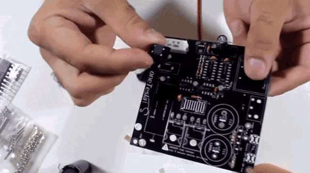 supple pollen
I just realized the AdaFruit Circuit Playground emoji don't include a (non light emitting) diode. However, it is possible (and indeed sometimes useful) to build a LED bridge rectifier.
tough matrix
we should get an emoji of smoke emitting diode
latent jungle
also known as a One-Time LED
 trim steeple
In one of my college electronics courses we had a cork board where people would put up all the various components from which the magic smoke had escaped. It was sad for me because I never got one up there. Then, on the last day of lab, I accidentally set the signal generator on my bench on fire
unique patio
supple pollen
Also known as a noise emitting diode
I've posted several pictures of such components on this Discord over the years
woven bluff
distant raven
https://tenor.com/view/electroboom-full-bridge-rectifier-full-bridge-gif-2466159...
what kind of lunatic draw a full bridge like that?
woven bluff
trim steeple
In one of my college electronics courses we had a cork board where people would ...
all is fun until a diode in plastic axial package exploded, I was deaf for like 5 minutes
I built a railgun for undergrad physics "design your own experiment", and used cheap Chinese FR307 (rated 1KV, 3A) for the main capacitor bank polarity protection. It exploded for no more than 400V reverse bias, that's when I learnt never trust the component rating, and never use cheap knock-offs.
distant raven
woven bluff
what kind of lunatic draw a full bridge like that?
Electroboom is kind of crazy, so him. He’s not alone, there are plenty of text books where you can find it draw than way.
trim steeple
His whole youtube channel is kinda like "What dangerous things can I do with electricity"