#help-with-hw-design
1 messages · Page 23 of 1
 slow plover
 paper vale
slow plover
Is it 370 RPM or is it RPM/V (aka k_V)
paper vale
slow plover
Is it 370 RPM or is it RPM/V (aka k_V)
they just said 370 RPM and the rated speed is 40 km/h max
slow plover
typically motors are given a nominal KV or voltage constant, 370 sounds plausible for an ebike
 bitter dune
What software is this?
slow plover
it's nominal RPM per volt from the speed controller under no load
 supple pollen
bitter dune
What software is this?
supple pollen
bitter dune
What software is this?
Eagle
paper vale
slow plover
it's nominal RPM per volt from the speed controller under no load
how to get the real speed of the shaft then ?
slow plover
paper vale
how to get the real speed of the shaft then ?
measure the wheel diameter and gear ratio, do a bit of math
bitter dune
Does anyone know of any decent hardware designs for a speaker to stream music to via wifi or bt?
Has anyone here integrated a radar chip into a device?
 left grove
bitter dune
Has anyone here integrated a radar chip into a device?
left grove
bitter dune
Has anyone here integrated a radar chip into a device?
Those cheap 24GHz human presence radar modules?
I have some that I hopefully test this/next week
Idk about the wifi or BT part. Esp32 or RP2040 can do it I think. But for the speaker part I highly recommend I2S amps if you're using a microcontroller. For example those max98357a if you want a direct speaker connection and don't need line out, an extra amp or something like that
bitter dune
left grove
Those cheap 24GHz human presence radar modules?
I have some that I hopefully tes...
Yeah exactly. I just came across them and thought it was neat. I was looking at some 50GHz model
bitter dune
left grove
Idk about the wifi or BT part. Esp32 or RP2040 can do it I think. But for the sp...
I keep running across this max98357a chip. Why is it so popular? Def seems like I need a chip for audio processing and/or amplification
left grove
I'm using the Max98357a. It's really simple to use and wire up (your MCU just has to output I2S), cheap, sounds surprisingly good and 3W is more than loud enough for me.
You just wire it up directly to the speaker.
It doesn't do any processing, decoding, etc though! So you have to do everything in software or I think with an additional codec chip or something like that.
Afaik
SD-Card -> MCU with WAV decoding and volume control in software -> I2S output to Max98357A -> speaker
Is basically the cheapest way you can do music quality audio for Arduino/CircuitPython stuff.
bitter dune
Seems simple enough
left grove
That might be why it's so popular. There are boards from adafruit and even cheaper ones
bitter dune
Ultimately I want to stream music
left grove
If you need line level output then there are other I2S chips I forgot their name
bitter dune
Either DLNA, Subsonic, spotify, etc
left grove
Direct Spotify streaming looks pretty much impossible for hobbyists to me 😭
bitter dune
left grove
If you need line level output then there are other I2S chips I forgot their name
I don't plan to need it for this, just driving a decent 3w speaker I think should suffice
bitter dune
left grove
Direct Spotify streaming looks pretty much impossible for hobbyists to me 😭
I can't imagine it's too hard to make a device show up as a spotify device? Idk though, but it seems like some basic API stuff
left grove
Basic API stuff behind billions of lines of legal stuff, copy protection, NDAs, etc
bitter dune
My background is in the programming side. All this hw stuff is pretty new to me.
bitter dune
left grove
Basic API stuff behind billions of lines of legal stuff, copy protection, NDAs, ...
Ha yeah...
left grove
at least it looked like that when I skimmed the Spotify API docs.
Stuff like controlling an official Spotify app, adding songs to playlist, etc seems very possible to me
bitter dune
My worst case hopefully is integrating spotify through home assistant
left grove
I have some Visaton FRS 8 4 Ohm. They work great but thb I don't know how much better they sound than those cheap speakers for example adafruit sells
you can use those 3W amps with like a 35W speaker no problem
bitter dune
left grove
you can use those 3W amps with like a 35W speaker no problem
Lol for real??
left grove
Yes
bitter dune
left grove
I have some Visaton FRS 8 4 Ohm. They work great but thb I don't know how much b...
Cool Ill look into them
left grove
Imho the adafruit docs are kinda bad in this regard. But the same goes for pimoroni, etc. Everyone just says "3W speaker" when you actually have way more choices.
Basically:
The W rating of the speaker is the maximum watts it can do. If you have a 3W speaker and blast a 30 W amp at full volume, then the speaker might break.
If you have a 3W Amp and a 30W speaker then literally nothing bad happens. The amp just drives the speaker with max 3W and that's it. Theoretically the speaker could do more. You're limited by the amp.
I think if you go completely overboard, there might be issues. Like I wouldn't drive a 100W subwoofer with that 3W MAX amp. 😄
But in my limited tests the Visaton FRS8 (30W) sound better than the FRS7 (8W).
Both with that Max amp. I don't think it's because of the extra watt rating, but because the FRS8 are just a bit larger
bitter dune
This makes sense
Though I know underdriving a speaker and blow it too
But itd be good to know rms rating vs max rating
I'm curious what woofer is in the echo dot
 left grove
I really need to build the speaker box. Haven't tested them with a box yet. Without box my speakers definitely don't have enough bass.
bitter dune
It's rather small and it faces down interestingly enough
bitter dune
left grove
I really need to build the speaker box. Haven't tested them with a box yet. With...
None of these have any bass. Imo you need at min an 8" woofer to have any bass
I think a 6.5" would be great though, way better than what most are used to these days
 worldly schooner
left grove
Basically:
The W rating of the speaker is the maximum watts it can do. If you h...
worldly schooner
left grove
Basically:
The W rating of the speaker is the maximum watts it can do. If you h...
I’m not sure if this is or isn’t a safe recommendation, but I also don’t think that’s how amplifiers work. If your amp tries to drive a speaker with too low a resistance, you can overdraw an amp and potentially cause damage to it.
left grove
Oh yes, the resistance has to match I think.
But afaik resistance and watt rating are separate things
bitter dune
left grove
Oh yes, the resistance has to match I think.
But afaik resistance and watt ratin...
Theyre related
left grove
Those visaton I mentioned are 4 or 8 Ohm (I have 4 Ohm), which is what that MAX amp wants according to its datasheet
I've used them like that for a few hours probably now
worldly schooner
Simply matching wattages isn’t sufficient for speaker/amp selection. Technically, audiophiles will recommend an amp with a higher wattage rating so there’s enough headroom to cover for the full dynamic range, and the speaker isn’t going to instantly burn out under slight overpowering.
That being said, extreme mismatches in either direction could be cause for issue, but wattage ratings alone don’t tell the full story.
supple pollen
Additionally, bigger speakers tend to be both capable of higher power and higher efficiency, so hooking a 100 watt speaker to a 1 watt amplifier will often give more volume (and better sound quality) than a 1 watt speaker would. Additionally, some amplifiers will go into clipping when overdriving, and in the process, deliver more than their rated wattage: this effect can damage speakers.
worldly schooner
It can also damage amplifiers.
left grove
supple pollen
Additionally, bigger speakers tend to be both capable of higher power and higher...
Very interesting
"additionally some amplifiers will go into clipping when overdriving"
What exactly is overdriving here? Like driving a 3W speaker with 10W? Or the other way around?
supple pollen
Like taking an amplifier that expects a 1 volt input and giving it a 10 volt input.
left grove
Ah thanks
worldly schooner
When in doubt, pick a speaker with an impedance rated for your amp. The wattage ratings are useful for establishing volume limits and efficiency, but shouldn’t necessarily be the primary metric for speaker or amplifier selection.
left grove
Exactly
My main point is that a lot of tutorials just say "get a 3W 4Ohm speaker" when you actually have more choice and could get a larger 7W 4Ohm for example
supple pollen
In general, that's a little leeway on impedance as well. You can often use a higher impedance speaker (within reason) and get fine results, just not as much power. An amplifier that can deliver 3W to a 4 ohm speaker will still work with an 8 ohm speaker, but possibly with lower wattage. Hooking it to a 600 ohm speaker, however, will generally not work well. Going the other way can be hard on amplifiers: if an amplifier is designed for a 8 ohm load, it may be unhappy with a 4 ohm load.
left grove
Very good to know. That MAX9something says I think 3W at 4Ohm and 1,8W at 8 Ohm or something like that
supple pollen
Obscure side note: vacuum tube amplifers are the other way around. Hooking a vacuum tube amplifier to a speaker that's too high impedance can overload the output transformer.
bitter dune
worldly schooner
Simply matching wattages isn’t sufficient for speaker/amp selection. Technically...
Mmhmm, too much power is better than too little power
I just got a pair of AKG K702s for my birthday. Apparently once an audiophile, always an audiophile. 😂
I've always wanted to produce my own woofer but I think I'm getting ahead of myself here.
But I bet a smart speaker with either a kevlar or carbon fiber based woofer would bump hard
This echo seems to have a polyurethane coated paper woofer. Which is nicer than I expected actually. Still trying to pop it out, it's really in there and the housing is steel!
supple pollen
When I'm going for exotic woofer cone material, I'm attracted by the aluminum ones.
bitter dune
supple pollen
When I'm going for exotic woofer cone material, I'm attracted by the aluminum on...
Aluminium you tend to see used for tweeters. They can be decent but often are on the bright side. Might be nice for a smart speaker
supple pollen
The aluminum cone woofers are generally aimed at the severe duty market (rock concerts, car audio, etc.) But the physics of them appeals to me, as aluminum is much stiffer than carbon fiber, which is strong under tension but weak under compression.
Some of them are visually appealing as well, like this Hartke cabinet.

The advantages of carbon fiber, Kevlar, etc. are high (tensile) strength by weight. The aluminum cones are going to be heavier, but at bass frequencies and with sufficient amplifier power, this doesn't concern me.
bitter dune
Ahhh yeah that makes sense. They get super loud for much cheaper.
I want to say kevlar is punchier and cf is clearer.
Kevlar imo is the best value for the sound overall, but you seem like you know how much of that can be personal preference
 last prairie
can someone explain this to me, is VBUS just going in a loop? As far as I understand it's connected to its self. (found in QT Py - SAMD21 Dev Board with STEMMA QT schematic)

 unreal flax
last prairie
can someone explain this to me, is VBUS just going in a loop? As far as I unders...
unreal flax
last prairie
can someone explain this to me, is VBUS just going in a loop? As far as I unders...
That looks like the 5V is coming from the USB connector and being distributed to the board from there.
last prairie
here is entire schematic... There is some other 5volt line next to it (top left) sorry should have provided whole thing.
 unreal flax
last prairie
here is entire schematic... There is some other 5volt line next to it (top left)...
unreal flax
last prairie
here is entire schematic... There is some other 5volt line next to it (top left)...
Gotcha. So that allows the board to be powered from USB (using the VBUS to +5V path), or by the 5V pin directly. Or the 5V pin can be used to also power something else from USB. The diode prevents back-powering the USB port.
But yes, it is a little circular in that everything is hooked together. The function just depends on where you supply the power from.
last prairie
thanks for the info
 sweet cairn
Yep I was planning on switching it out but wanted to make sure if I want to make the switch to tantalum before doing it
Yeah I realised that later on lol 😅
Oh interesting, I didn't know that!
Thanks a lot!
I suppose I'll go with C0G for C6 and C7 and tantalum for the other caps. I'm glad I asked here beforehand lol
 candid orchid
Why do i get ERC error on this?
 paper vale
Hello. what will be the direct consequence using a high value inductor for a buck regulator ? Example : 110uH instead of 3.3uH for example ?
 unique patio
paper vale
Hello. what will be the direct consequence using a high value inductor for a buc...
unique patio
paper vale
Hello. what will be the direct consequence using a high value inductor for a buc...
https://electronics.stackexchange.com/questions/256008/what-will-cause-if-i-put-a-larger-inductor-to-a-step-down-converter-like-mp1584. This is not going to work out well. The datasheet recommends a specific inductor range for good reasons.
 rustic linden
candid orchid
Why do i get ERC error on this?
rustic linden
candid orchid
Why do i get ERC error on this?
KiCAD is just weird like that. Check the power tag menu, and there should be a PWR_FLAG, and you need to put one for VCC and GND
 latent jungle
candid orchid
Why do i get ERC error on this?
latent jungle
candid orchid
Why do i get ERC error on this?
It's because of how KiCad handles Power pins. A Power pin can be a Power Input (load) or a Power Output (source). If you had a voltage regulator it's input pin would be a Power Input and its output would be a Power Output).
VCC (and the other power nets) and the Battery / BT1 are not defined as Power Output. VCC isn't because it's just a net name. The battery isn't because it could be either (depending if it is charging or discharging.)
So ERC is tell you that VCC and GND have no implicit "driver." As mentioned, adding a PWR_FLAG to each node will resolve the ERC error. Ideally, you should put them between the VCC / SW8 and the GND of the battery, since those are your "Power Outputs" in this case.
latent jungle
paper vale
Hello. what will be the direct consequence using a high value inductor for a buc...
Unless you have significant experience designing a switch-mode power supply, you want to follow them manufacturer's example designs as closely as possible--especially the PCB layout. While we like to describe SMPS circuits as this simple "you excite the inductor and smooth it with the capacitor" kind of thing, there is a complex interaction going on. (There is an error amplifier inside of the switch-mode controller and that amplifier has a loop bandwidth (like all amps.) By changing either the L or C significantly, you change the response of that amplifer.)
(and no, the answer isn't always as simple as: if I use a larger inductor, that means I can use a smaller capacitor!)
 distant raven
latent jungle
(and no, the answer isn't always as simple as: if I use a larger inductor, that ...
distant raven
latent jungle
(and no, the answer isn't always as simple as: if I use a larger inductor, that ...
gasp
All that theory I learned down the drain! Lol 😂
That’s the nuance that circuit analysis courses need
You may get the same frequency response but those LC filters do more than just attenuate signals.
latent jungle
distant raven
You *may* get the same frequency response but those LC filters do more than just...
Exactly. (and in a lot of cases it might work.) But also, it demonstrates the need to test SMPS circuits--especially with more than a DMM since lie.
distant raven
I’m be satirical with my theory comment
Mostly because my circuit analysis courses lacked the nuance that experience gives you
Which is also a problem with a lot of undergrad circuit analysis courses
But my Linear Systems and Signals class was pretty good at filling in the gaps. Those laplace transforms take you a long way
latent jungle
Yeah. And school tends to focus on older parts. As switchers get faster, the details become more critical. (Which seems like a common thread across electronics.)
distant raven
Top schools probably do a better job than the average state school teaching EE
First exam for my linear systems and signals class

It was a rough test
latent jungle
distant raven
First exam for my linear systems and signals class
lol, I just got flash backs to being a grader / TA in school.
I need to buy a box of red pens for nostaliga.
distant raven
A much better exam

Nowadays I’m doing software engineering
Well, embedded stuff with my side hustle
But mostly software at my day job 🥲
 inland jungle
is there a jobs channel here where we can find people looking for work?
worldly schooner
inland jungle
is there a jobs channel here where we can find people looking for work?
See #help-with-community message for our current stance on paid work.
 fickle patio
Looking for some pointers regarding the ADC pins on a Pico W. Apologies for the long post! TLDR- my ADC pins all read high for a short moment and I don’t know why.
Details:
I’ve connected the Pico’s ADC2 to the audio output of a telephone interface IC via a coupling capacitor.
When the phone is taken off the hook and this audio line first becomes active, both of the Pico’s other ADC pins very briefly read high (65xxx). Even if I set those pins as GPIO with a pull down (using digitalio instead of analogio), I still see this momentary spike of the pin reading True.
This causes issues because I want to use one of those other ADC pins as a trigger, and this spike is causing false alarms.
If I move my trigger pin to a non-ADC pin the issue is solved. I could also solve it in software with a longish debounce, but I’d rather correct the issue at the source.
Is there something obvious I should be doing to prevent one ADC pin from influencing the other two?
latent jungle
fickle patio
Looking for some pointers regarding the ADC pins on a Pico W. Apologies for the ...
I’ve connected the Pico’s ADC2 to the audio output of a telephone interface IC via a decoupling capacitor.
decoupling or coupling?
fickle patio
latent jungle
> I’ve connected the Pico’s ADC2 to the audio output of a telephone interface IC...
Coupling! Thank you, I’ll edit my post
latent jungle
how big is that cap?
fickle patio
.1uF, as called for by the datasheet of the chip
latent jungle
Can you draw a schematic or block diagram of what you wired up?
fickle patio
I’d be happy to post that, but I really can’t expect anyone to look it over! It’s my first attempt at a PCB and it looks like this
 latent jungle
backing up, if multiple pins are affected, then probably have some kind of crosstalk issue. what doesn't make sense with that, though, is that there is only one analog-to-digital converter. The inputs are read through a multiplexer--aka, one at a time. So that suggests whatever is driving the pins high is a very slow, very strong signal.
fickle patio
Indeed, when I read the values of the other ADC pins as analog (so, no pull down) I see the value drop from 65xxx down to 12xxx over about 2 seconds
latent jungle
with nothing connected to them?
fickle patio
Well, one has a simple momentary contact switch attached (N.O.) and the other has just a short trace leading to an unconnected header
supple pollen
fickle patio
Looking for some pointers regarding the ADC pins on a Pico W. Apologies for the ...
The phone circuit is normally at 48V or so, so when you go on or off hook, there will be a 48V (ish) spike. Ringing voltage is even higher, often on the order of a hundred volts at 20Hz or so. Presumably the interface IC deals with some of this, but it can be tricky depending on grounding arrangements, distributed inductance, etc.
latent jungle
supple pollen
The phone circuit is normally at 48V or so, so when you go on or off hook, there...
well, not the audio circuit at the handset
(obviously, depending on the phone)
fickle patio
supple pollen
The phone circuit is normally at 48V or so, so when you go on or off hook, there...
The IC does indeed deal with the line and ringing voltage.
It has separate pins for audio to and from the handset, which presumably are isolated from these voltages, no?
I’ve followed the datasheet’s application notes, and it doesn’t mention any additional circuitry regarding the audio besides the coupling cap
supple pollen
I don't know if they're isolated, it depends on the chip, I suppose
latent jungle
Well, you haven't said what "the IC" is yet, so it is tough to say.
It might be why someone asked about a schematic or basic block diagram a while back
Not to be mean, but you've essentially asked: "My project's IO pins aren't working, why?"
With zero details.
latent jungle
and how are you using this pcb (not an IC)?
supple pollen
It could be that you don't have any baseline setting resistors on the ADC side of the capacitor, so when the level changes, it takes a bit for the capacitor to discharge
fickle patio
latent jungle
and how are you using this pcb (not an IC)?
I’ll post my (bad) schematic, as that seems to be the most complete way to answer your question.
But! As I said earlier (and as you can obviously tell) I am new to this, did not go to school for it, etc. As such, I’m not looking for or expecting free tutoring.
If I’m not able to adequately answer your questions, and there isn’t an obvious easy thing I’ve overlooked (like “just throw a capacitor here”) it’s probably best to move on and not waste everyone’s time
 supple pollen
I'm guessing you need a resistor, not a capacitor

Perhaps two 10k resistors in series to form a voltage divider between the Pico supply and 0V, with a resistor from the junction to the Pico side of the capacitor.
 cursive sentinel
fickle patio
The IC does indeed deal with the line and ringing voltage.
It has separate pin...
cursive sentinel
fickle patio
The IC does indeed deal with the line and ringing voltage.
It has separate pin...
Phone systems running at these voltages predate ICs by... actually I'm not sure, but likely well over 50 years. Keep in mind that at one time phone systems were predominantly electromechanical (with tube-based amplification). And before that, it was manual and unamplified. In both cases, there was good reason to run at high voltages.
fickle patio
supple pollen
Perhaps two 10k resistors in series to form a voltage divider between the Pico s...
Thanks. Is this called setting a bias? And can you help me understand how this would help to prevent a voltage spike on A2 from effecting A1 and A0?
supple pollen
Yes, it's setting a bias, and it's also providing a discharge path for the capacitor. I missed the detail about a signal on one input affecting other inputs. That could be conduction from the input protection diodes, ground bounce, power supply noise, or just cross-coupling (in many chips, the various analog inputs share a digitizer, which is switched from one input to another as needed).
fickle patio
You’ve given me such a bounty of research topics 🙂 I’m very grateful.
I got into this mess because I was working in Eagle late one night, and had the bright idea that I should break out those pins just for funsies. Now that I have a board printed, I have to deal with them 😹
fickle patio
latent jungle
and how are you using this pcb (not an IC)?
Earlier, I wrote “it’s probably best to move on and not waste everyone’s time” and I’m worried that came across as directed toward you. A better sentence would have been “it’s probably best for me to move on and not waste everyone’s time.”
My apologies if that came across super rude earlier.
latent jungle
fickle patio
Earlier, I wrote “it’s probably best to move on and not waste everyone’s time” a...
no worries. I’ve heard worse. and probably said more worse.
latent jungle
(And apologies if my tone went the other way.)
supple pollen
I've had similar experiences after I had a board made. In this particular case, I had designed a computer controlled light dimmer, and the first boards ended up not working how I wanted them to. Then later, I had a need for 4 independent mains voltage flashers (replacing the old thermal kind that seem to no longer be available). I was able to retread one of the old 8-channel dimmer boards as a 4-channel flasher board, testing the modified software by stuffing LEDs into the optocoupler sockets.

 tribal perch
Hi, I'm designing a basic fan control circuit, using an RP2040 as the controller, with a potentiometer for the control input.
I want to try and be power efficient with the potentiometer, rather than keep it connected to the voltage rail constantly I plan to enable power before taking a mesaurement with the ADC. This is what I've come up with using one of the transistors available as free issue from my chosen PCB fab. POT_DIS and POT_OUT would connect straight to the RP2040 GPIO pins.
Is this a suitable design? or have I naively overlooked something fundamental?

I have just fixed the direction on the POT_OUT label too.
supple pollen
The RP2040 would be doing what? Generating PWM? In most cases, you would connect the transistor emitter to ground and the potentiometer end to 3V3
latent jungle
tribal perch
Hi, I'm designing a basic fan control circuit, using an RP2040 as the controller...
Yes, that will work to drop a voltage across the POT. Just remember that the logic is inverted in a high-side switch. A HIGH from the RP2040 puts 3.3 volts on the base, which turns off the PNP and a LOW puts 0V, enabling it to turn on.
supple pollen
I'm also unclear where you are hooking the fan up
latent jungle
From the description, they want to use the ADC to measure the voltage across the pot and then they'll (likely) use PWM to adjust the fan (controlled from something else.)
Arguably, if you're running a fan, the 300 uA the POT draws is probably irrelevant.
supple pollen
It might be easier to just hook the top of the potentiometer directly to a GPIO if they just want to power the pot when it's being read
tribal perch
So, the fan is going to be a 5V PWM noctua A12x25 (https://noctua.at/en/products/fan/nf-a12x25-5v-pwm).
I'm going to be driving the fan PWM via a GPIO (and level shift), and reading the fan Sense line via GPIO (and level shift).
This POT is to control the desired fan speed.
You're right, I could also drive the Pot from a GPIO rather than the transistor; but I thought coming from the 3v3 rail would give more headroom than sourcing through a GPIO.
latent jungle
headroom for what?
tribal perch
Current sourcing. But yes, the 300uA is a lot less than I (somehow) initially thought.
So the GPIO should be able to supply that easily
latent jungle
It's just ohm's law. 3.3 volts / 10 kohms = 330 uA.
tribal perch
I think I worked the opposite way around. Assumed the current wouldn't be able to be sourced from the pin; and designed around the transistor first. Then selected the size of the pot
¯_(ツ)_/¯
Oh well, question answered anyway. Thank you very much @latent jungle @supple pollen .
latent jungle
A 10K pot is a suitable choice for this use. It's large enough it doesn't waste much power and it is small enough it won't be very noisy when reading it.
100K would probably work well too
paper vale
Hello. what will happen if we connect 2 stabilized power supplies in series and the same current limit in order to get a higher voltage for the load ?
supple pollen
If they're not floating power supplies, one of them will short circuit. If they are floating power supplies, you'll the the sum of the voltages at the two ends.
paper vale
supple pollen
If they're not floating power supplies, one of them will short circuit. If they...
What do you mean by floating please ?
I think it’s just connecting 2 voltage sources in series ?
supple pollen
Some power supplies that plug into mains connect one terminal of their output to ground.
If you try to put two of these supplies in series, you end up connecting both terminals of one of the outputs to ground, which short-circuits that power supply.
rustic linden
My power supply for example has the option to tie ground to earth
supple pollen
Those are handy. This one that AdaFruit used to sell does too: https://cdn-shop.adafruit.com/970x728/2014-01.jpg
 rustic linden
ooh fancy
 cursive sentinel
You'll have to check the datasheet.
rustic linden
According to the website, the ground is isolated, so I believe that's floating?
cursive sentinel
Yeah
supple pollen
You can always test it yourself. Hook a 1k resistor from the + output of one to the - output of the other, leave the other terminals unconnected, and turn them both on. Then measure the voltage across the resistor. If it's zero volts, you're good.
paper vale
cursive sentinel
You'll have to check the datasheet.
Looking at the datasheet I think it’s floating output ?
 paper vale
supple pollen
You can always test it yourself. Hook a 1k resistor from the + output of one to...
paper vale
supple pollen
You can always test it yourself. Hook a 1k resistor from the + output of one to...
I saw floating ground. So it can be connected in series ?
cursive sentinel
paper vale
Looking at the datasheet I think it’s floating output ?
Yeah.
latent jungle
The easiest (non-datasheet) way is to just test it with a multimeter. Unplug it from mains. Then use continutity mode to test from the negative output terminal to the ground connection on the AC cable.
If that's a short, the output isn't floating.
candid orchid
How can i fill copper in spaces between traces correctly? If i do a 'no net' pour, i get this cutout around the trace of the zone. I do not need this zone to be connected to anything.

Ahh, i found out.. 'never remove islands'
worldly schooner
candid orchid
Ahh, i found out.. 'never remove islands'
Don’t say never, islands should definitely be removed in some cases. Perhaps not in your case, but see https://electronics.stackexchange.com/questions/257585/should-we-remove-unconnected-copper-island-among-connected-traces for some reasons why the option is offered in the first place.

Electrical Engineering Stack Exchange
Currently designing a PCB I find out there are some copper island. I was wondering if we should better keep them or remove them and why ?
Is there any manufacturing risk of having those ?
candid orchid
Yes, they are only for astetics. So i'm not worried about them acting as antennas
distant raven
worldly schooner
Don’t say never, islands should definitely be removed in some cases. Perhaps not...
This is a great point. Thanks for sharing
 limpid nest
For a hall effect switch like this, if I'm detecting the field from a bog standard neodymium magnet, does the flat part of the magnet need to be parallel to the plane of the PCB this is on?

 dry pelican
Yes
worldly schooner
Doesn’t have to be perfect. The angle will affect sensitivity to some degree, though.
supple pollen
limpid nest
For a hall effect switch like this, if I'm detecting the field from a bog standa...
It depends on which axis your magnet is magnetized.
limpid nest
supple pollen
It depends on which axis your magnet is magnetized.
Is there a scenario where I could mount a board with the shaft through the plane of the board and put a magnet on the shaft and have it trigger a switch like this?
worldly schooner
limpid nest
Is there a scenario where I could mount a board with the shaft through the plane...
Well, that would depend on the direction the shaft is moving the magnet.
limpid nest
worldly schooner
Well, that would depend on the direction the shaft is moving the magnet.
Do you mean CW/CCW?
worldly schooner
If the shaft is turning on an axis perpendicular to the board, that switch is not a good fit.
dry pelican
there are rotary hall encoder ICs
pretty cool
use an axially polarized magnet (I think that's what it is called) above the sensor and it can read the angle with high precision
 west apex
Anyone have favorite gEDA & pcb tutorials? I've never used that software but I'm trying to work with an existing open design, need to swap out a single footprint since original part was discontinued.
 timid parrot
Trying out one of these UART ultrasonic sensors: https://www.adafruit.com/product/4664 with this FTDI serial port https://www.adafruit.com/product/70 under MacOS using the terminal command
screen /dev/tty.usbserial-A9071JUY 9600
I get some response, but it is gibberish a la
�������������������/0�/0�/0�������kp�kp�kp�������������������������������������������AC�AC�AC�$%�$%�$%�$%�$%�$%�$%����9:����
The Adafruit guide for the sensor says 9600 baud, but maybe I'm missing something and/or that number needs to be updated? Any guidance here would be appreciated. Thanks!
This impressive-looking horn is actually an ultrasonic sensor, ready for panel mount use. Inside is a module that uses high-frequency signals to determine distance to a surface, and the horn ...

Just about all electronics use TTL serial for debugging, bootloading, programming, serial output, etc. But it's rare for a computer to have a serial port anymore. This is a USB to TTL ...
Similar results using the Arduino IDE serial monitor
unreal flax
timid parrot
Similar results using the Arduino IDE serial monitor
That may be correct data. The datasheet says it's a binary protocol, not ASCII text, so you'd want to look at the hex bytes to see if it's legit. Real data will be 4-byte packets starting with 0xFF.
 inland mist
hey - do you know of any website that has Arduino Mounting hole schematics?
I've already googled but could not find reliable data...
I have a green Arduino Leonardo with headers pre-installed and Want to 3D print a little part for a DIY PCB that mounts above the middle of it.
The official documentation website with the schematics technically has the holes in the PCB design but it does not let me correctly measure things and the non-linear hole locations make it pretty unsuitable for measuring it myself.
@ me in replies!
unique patio
timid parrot
Trying out one of these UART ultrasonic sensors: https://www.adafruit.com/produc...
datasheet, as linked from product page: https://cdn-shop.adafruit.com/product-files/4664/4664_datasheet.pdf
latent jungle
inland mist
hey - do you know of any website that has Arduino Mounting hole schematics?
I've...
What did you search? I searched Arduino Mounting hole and the very first link was a forum post that leads to this pdf from Adafruit: https://cdn-shop.adafruit.com/datasheets/arduino_hole_dimensions.pdf
timid parrot
Ths @unreal flax @unique patio - Ran the Arduino IDE example code https://github.com/adafruit/Adafruit_Learning_System_Guides/blob/main/DYP_ultrasonics/me007ys/me007ys.ino
and was initially a bit confused because the actual computer serial monitor is set to 115200, while the sensor itself is 9600. Thx for the clue on that one.
On a related note, if I did want to get more intelligible data out of screen, is there a setting on this type of serial monitor for hex bytes or even binary rather than ASCII?
unique patio
timid parrot
Ths <@382380426628562955> <@329766224093249548> - Ran the Arduino IDE example co...
this looks interesting: https://learn.sparkfun.com/tutorials/terminal-basics/real-term-windows
but the .ino script should be doing what you want. You could also write a Python script using pyserial to do what you want.
not sure if there's naything like RealTerm for macOS
timid parrot
Thx. I love the terminal options in MacOS most of the time, but sometimes not so much. That Serial program does look interesting.
Do UART sensors typically use a binary protocol, or do others use ASCII?
unreal flax
timid parrot
Do UART sensors typically use a binary protocol, or do others use ASCII?
It varies. GPS devices tend to send text in a standard NMEA format, for example.
unique patio
timid parrot
Thx. I love the terminal options in MacOS most of the time, but sometimes not so...
some things use AT-style commands (like old modems, etc.)
this https://www.adafruit.com/product/3686 is also binary serial
I think there is no "typically' rule of thumb that would help you
timid parrot
unique patio
I think there is no "typically' rule of thumb that would help you
Ha, well thanks!
 tough matrix
new experience for me... needed to change resistor value on Adafruit Feather board (LiPo battery charging circuit; provided resistor is 5.1k which gives 200mA charging current, I needed to replace it with 2k, to get 500 mA current).
Of course I could have desoldered it and put a new one in place, but it is so tightly packed that resoldering just this resistor is tricky.
So I did what I saw don't remember where and stacked another resistor, 3.3k, on top, effectively connecting them in parallel.
worked really nice
Now I just need to learn to do it fast.
inland mist
latent jungle
What did you search? I searched `Arduino Mounting hole` and the very first link ...
"Arduino Leonardo Mounting Hole" and everything comes but not the Leonardo!
latent jungle
inland mist
"Arduino Leonardo Mounting Hole" and everything comes but not the Leonardo!
Ah. Leonardo and Uno (and previous) have the same hole pattern.
inland mist
ohhh did not know that... thanks!!
timid parrot
So different HW question - trying to figure out how to change the BME280 I2C sensor https://learn.adafruit.com/adafruit-bme280-humidity-barometric-pressure-temperature-sensor-breakout/pinouts address around in the software (to 0x76) and I have yet to find this in the library docs https://github.com/adafruit/Adafruit_BME280_Library - could someone point me in the right direction here? Thx!
latent jungle
Interesting, BME280_ADDRESS_ALTERNATE is defined as 0x76 ...
latent jungle
timid parrot
So different HW question - trying to figure out how to change the BME280 I2C sen...
https://github.com/adafruit/Adafruit_BME280_Library/blob/e4fe621df78b7dd8a2aff8f6613c67ca10d955d0/Adafruit_BME280.h#L219 line 218 looks like where the addr is defined for the library. I don't know how else to do it than change that to BME280_ADDRESS_ALTERNATE . (I'm not good when it comes to C++ stuff).
I am sure there is another way
timid parrot
latent jungle
I am sure there is another way
Hmm, thx. Was thinking there was a way to do this in the .ino code, but didn't see that documented.
latent jungle
timid parrot
Hmm, thx. Was thinking there was a way to do this in the .ino code, but didn't s...
There probably is, but I'm not smart enough to figure it out. Did you try just doing .begin(0x76)?
timid parrot
latent jungle
There probably is, but I'm not smart enough to figure it out. Did you try just d...
Ha, well I did not. Where would I input that, in the .ino code or the library?
latent jungle
timid parrot
Ha, well I did not. Where would I input that, in the .ino code or the library?
The advancedsettings example shows how to do it:
if (! bme.begin(0x77, &Wire)) {
limpid nest
I have a single phase perm cap motor. How do I figure out what this diagram means? What does line mean here?
 supple pollen
"line" is the AC line or mains input
limpid nest
That's what I was thinking. I'm used to load. Where does neutral go?
Is one neutral and one hot?
supple pollen
That I'm not sure about. It would make sense, however. What does the 230V diagram look like?
limpid nest
supple pollen
That I'm not sure about. It would make sense, however. What does the 230V diag...

 spice zenith
TIL. The Feather specification page at https://learn.adafruit.com/adafruit-feather/feather-specification shows both pairs of mounting holes as 0.7" centers. However, some of them including the ESP8266 feather that I'm using in my current project, use smaller holes (which I knew about), but on a 0.75" center. https://learn.adafruit.com/adafruit-feather-huzzah-esp8266/downloads No wonder the holes in my 3d printed mounts haven't been lining up properly. 🙂
 lime herald
timid parrot
Thx. I love the terminal options in MacOS most of the time, but sometimes not so...
lime herald
timid parrot
Thx. I love the terminal options in MacOS most of the time, but sometimes not so...
the "luxury" terminal program for most mac users is iTerm2 (which is oddly on version 3...). Not sure it will do what you're looking for in terms of outputting hex but it's very powerful and is a huge improvement of the bundled terminal program
candid orchid
Which type of numbering on connectors do you prefer?

 dark grail
typically, the same numbering as whatever your plugging into
https://pinout.xyz/
the rpi for example, best matches J1
rustic linden
I'm mostly used to J2
supple pollen
I used to use ZTerm on Mac, these days I usually use CoolTerm. I'll have to look at iTerm2.
I normally use the odd/even (J1, center) numbering on Berg type connectors, as it maps to wire positions in ribbon cables.
latent jungle
Cathode is the best terminal, on macOS or otherwise
latent jungle
candid orchid
Which type of numbering on connectors do you prefer?
Personally, I use the layout that matches the footprint I am using.
For connectors, I like my nets in the schematic to follow the same physical layout of the PCB.
cursive sentinel
Odd-even is the most common scheme for connectors.
But yeah use whatever makes most sense for your layout.
 urban lark
Am I correct in thinking I can double up these mosfet breakouts, and get closer to 3amps continuous rather than 1.5amps each?https://www.adafruit.com/product/5648
The mosfet can each take 3.6A, but the breakout board clearly states 1.5Amp continuous so it's more a case of heat dissipation. They wont be on for more than 30 seconds at a time (pulsed on and off by someone manually via a dashboard like a door buzzer)
Sparky the Blue Smoke Monster shows up whenever the magic smoke is let out of an electronic component. And his very favorite is whenever folks first start with electronics and robotics: ...
lime herald
latent jungle
Cathode is the best terminal, on macOS or otherwise
I'll have to check that out
If I were doing numbering from scratch on my own thing, I'd probably go with J2 as DIPs number their pins that way and I grew up with them. That's a pretty arbitrary choice on my part.
supple pollen
urban lark
Am I correct in thinking I can double up these mosfet breakouts, and get closer ...
That might work, since MOSFETs have a positive temperature coefficient, so they tend to share load. Or you could just use a chonky TO-220 case transistor.
urban lark
supple pollen
That might work, since MOSFETs have a positive temperature coefficient, so they ...
Chonky sounds like the sensible route, but I'm hoping I can get away with just one of them, but advising someone else to do that feels foolish. No soldering intended.
latent jungle
urban lark
Am I correct in thinking I can double up these mosfet breakouts, and get closer ...
The mosfet can each take 3.6A, but the breakout board clearly states 1.5Amp continuous so it's more a case of heat dissipation
Yes, heat dissipation, but also what Vgs drives it. Figure 5 of the datasheet shows how at 3.6 Amps of drain current, the Rds-on changes from almost 100 millohms to almost 40 milliohms if Vgs is 3.3 volts versus 5 volts.
I dunno, 3 amps through a SOT-23 seems like a tough one to me.
paper vale
hello. I would like to add a low-pass filter at the input of the operational amplifier used to measure the phase current of a motor. What cut-off value is recommended for the filter? The PWM switching frequency chosen is 25kHz.
supple pollen
paper vale
hello. I would like to add a low-pass filter at the input of the operational amp...
It depends on the kind of filter, how much ripple you're willing to accept, and how much time accuracy you need in your measurements. There are formulæ to calculate all that. Normally I don't need a lot of speed from motor feedback, so I'd probably set the cutoff low, like a few hundred hertz, assuming something simple like a single pole RC filter.
inland jungle
Also related, how often are you measuring
latent jungle
fwiw, I really like using this filter tool as a starting point: http://sim.okawa-denshi.jp/en/Fkeisan.htm
distant raven
latent jungle
fwiw, I really like using this filter tool as a starting point: <http://sim.okaw...
I’ve used their Sallen-Key filter tool. I really liked it
inland jungle
is there an SPI booster IC similar to the I2C booster that Adafruit stocks?
cursive sentinel
SPI is push-pull, so you can just use a regular buffer or line driver.
74AHC125 is a good option.
Just make sure you get the directions right.
inland jungle
is there any advantage to putting the MISO on the buffer if it's near the MCU? The sensor has to drive almost all of the line anyways, is the buffer better at inputting the I/O than the MCU?
 broken zenith
Does anyone know of a cheap battery protection IC for a 40mAh LiPo coin cell? I don't expect to draw more than 0.5C at any given time, and I need short circuit, over current, and under voltage protection. I was eyeing the BQ297xy series, but they require external MOSFETs. I don't know how to pick a FET, and the one they recommend is over a dollar (!!!) and I'd need two. Open to suggestions either way - either a cheaper FET or a different IC altogether. Thanks!
 rigid plume
broken zenith
Does anyone know of a cheap battery protection IC for a 40mAh LiPo coin cell? I ...
rigid plume
broken zenith
Does anyone know of a cheap battery protection IC for a 40mAh LiPo coin cell? I ...
Hi can anyone guide me on VIA stitching for an WiFi 5 RF path (RF switch to Chip antenna and IPX), is what i've done fine?

 rigid plume
broken zenith
Does anyone know of a cheap battery protection IC for a 40mAh LiPo coin cell? I ...
rigid plume
broken zenith
Does anyone know of a cheap battery protection IC for a 40mAh LiPo coin cell? I ...
quite hard to find an integrated batt protection ic with inegrated fets (i don't think there is any). look at this https://www.ablic.com/en/doc/datasheet/battery_protection/S8261_E.pdf
urban lark
latent jungle
I dunno, 3 amps through a SOT-23 seems like a tough one to me.
Might do some thermal measurements, be intriguing to see how they hold out, but it's powering a car horn so it's more about how long I can hold out 😅
cursive sentinel
inland jungle
is there any advantage to putting the MISO on the buffer if it's near the MCU? T...
No. The buffer for that has to be on the 'far' side.
inland jungle
Sounds good, I can use the CS line to enable /disable the MISO buffer as well
broken zenith
rigid plume
quite hard to find an integrated batt protection ic with inegrated fets (i don't...
Thanks, I didn't know that. Any recommendations for a battery protection IC + FETs that meets my earlier requirements and is fairly cheap (<$2)?
cursive sentinel
inland jungle
Sounds good, I can use the CS line to enable /disable the MISO buffer as well
Yeah, you might want the 74x126 then. Either that or the '125 has inverted output enables, and I can't remember which.
supple pollen
broken zenith
Thanks, I didn't know that. Any recommendations for a battery protection IC + FE...
Maybe DW01 protection IC and AP2302 MOSFETs? Both are a few cents apiece from LCSC.
dry pelican
Agreed
dry pelican
rigid plume
Hi can anyone guide me on VIA stitching for an WiFi 5 RF path (RF switch to Chip...
It doesn't look wrong, but I've also never done RF so idk
 spice turtle
Hardware design question: Is it ok to have both SPI and I2C busses on my board? I am not really finding I2C 7 segment display drivers but there are quite a few for SPI.
 faint rain
spice turtle
Hardware design question: Is it ok to have both SPI and I2C busses on my board? ...
faint rain
spice turtle
Hardware design question: Is it ok to have both SPI and I2C busses on my board? ...
It's very common on MCU boards.
unreal flax
Yep, they don't interfere or anything.
spice turtle
are there any special considerations to take into acccount? I will try to not have them close to each other as possible
unreal flax
spice turtle
are there any special considerations to take into acccount? I will try to not ha...
You really don't need to worry. They're both pretty "normal" signals, and shouldn't cause any problems for each other. Lots of boards use both.
spice turtle
Thanks 🙂
rigid plume
Hi, what do you folks think of this header pinout, I'm using the RT106S and I'm trying to utilise all the features.
 paper vale
Hello. Using the parameters input what will be the voltages at the output of the opamp and the one which goes to the comparator ?
 supple pollen
The input to the comparator will be 2V, and the op-amp output will depend on the feedback resistor ratio.
paper vale
supple pollen
The input to the comparator will be 2V, and the op-amp output will depend on the...
The gain is 20 as mentioned.
Why they will be 2V to the comparator ? Even with Vin ?
supple pollen
You show that point as 2V. So basically you'll create 1.99V across the resistor between the 2V point and Vin.
If the op-amp is configured for a gain of 20, with 2V in, and a 5V supply, the output will go more or less to 5V (how close it gets to 5V depends on the op-amp's capabilities, not all of them can drive the output all the way to the supply rails)
paper vale
supple pollen
If the op-amp is configured for a gain of 20, with 2V in, and a 5V supply, the o...
Correct me if I’m wrong. The input is a AC signal. On the output of the opamp, don’t we get (0.01 x 20) + 2V = 2.2V ? And the voltage to the comparator 2V + 0.01 ?
supple pollen
You show 2V connected to the non-inverting input and to the comparator.
So the input is basically ignored, and just generates a current through the resistor to the 2V node.
If you wanted to add 2V to your input voltage, you'd need a different circuit configuration (there are several ways to do things like that)
paper vale
Look at this AN
 supple pollen
Yes, R1 decouples the inputs from the voltage source: that part is critical. It doesn't really just add the voltage, it combines them in the ratio of the conductances. Another way to think of it is as a voltage divider between Vdd and the input voltage.
paper vale
supple pollen
Yes, R1 decouples the inputs from the voltage source: that part is critical. I...
I modify the circuit. Look at this please. What voltage will be at the + pin of the opamp ? And what voltage will be at the output of the opamp ?
 supple pollen
Not enough information to say. It would depend on the voltage of Voffset, the values of R2, R^, Rlp, and Rs, the voltage at the top of the transistor, and how much the transistor is conducting.
If you assume the transistor is fully conducting, the voltage would be a voltage divider between the voltage at the top of the transistor and Voffset, depending on the ratio between R2 and (R^ + Rlp)
If you assume the transistor is fully nonconducting, the voltage would be a voltage divider between Voffset and ground, depending on the ratio between R2 and (R^ + Rlp + Rs).
paper vale
supple pollen
If you assume the transistor is fully conducting, the voltage would be a voltage...
The transistor is the low side one not the high side. I’m trying to measure the phase current of a 3 phase motor
Rlp and Clp form the input filter. R1 and R2 are used to set the gain of the amplifier. Voffset is used to add a DC offset of 1.65V to the signal. Cf and C2 are used to reduce the bandwidth of the opamp and to filter the common mode noise. At least that’s what I expected
supple pollen
Ah, Rs is presumably the current sense resistor, which is likely a low value, providing a low-impedance, low-voltage signal you want to measure.
paper vale
Yes exactly
supple pollen
You'll still get a voltage divider, so it won't just add X volts, just provide a voltage somewhere between Voffset and the voltage across Rs, depending on the ratio of the values of R2 and (R^ + Rlp)
paper vale
What is the solution then ?
I want the output of the opamp to be V = (Rs x I x G) + Voffset and the voltage at the + pin to swing be relative to the offset. So at 0A I want 1.65 at the + pin. At 15A I want 1.65 + (0.005 x 15). I don’t know if will get these results using the schematic here

 alpine knot
Does the uf2 samd21 bootloader support boards without additional spi flash?
supple pollen
I don't think you'll get those results from that schematic. There are a few approaches, depending on how many op-amps you want to use, whether AC coupled signals are acceptable, etc.
distant raven
alpine knot
Does the uf2 samd21 bootloader support boards without additional spi flash?
Not that I’m aware of
I’m not personally aware of a boot loader that allows you to. You might be able to do a custom boot loader with microchip studio to utilize SPi flash though
alpine knot
distant raven
I’m not personally aware of a boot loader that allows you to. You might be able ...
I might've asked an ambiguous question 😅 , I'm working on a custom board based on the itsybitsy m0. I'm not planning on using CircuitPython so I don't think I have a need for the SPI flash that I believe is included to allow the USB drive functionality that makes enables easy CircuitPython development. Can I omit the flash from the board but keep using the same bootloader?
distant raven
Yeah, the samd21 QtPy is that way
 balmy condor
moved to #help-with-audio
paper vale
supple pollen
I don't think you'll get those results from that schematic. There are a few app...
What’s wrong with this design ?
spice zenith
I've got a project currently using a Pi zero w and a 3.5" pitft display: https://www.adafruit.com/product/2441
The Pi zero w network connectivity has suddenly dropped to the point of no longer being usable: Typically I boot the thing up, open a putty session, and within a few minutes the connection is dropped.
It's not a range issue, there's a bunch of wifi bulbs in the same room (TPLink Kasa KL-125s) and they're all working just fine. Plus my cell phone shows a rock solid wifi connection there as well.
So I got to thinking. The display claims it uses high speed SPI. Could that be driven, albeit at lower speed, by a regular SPI connection from (e.g.) an ESP32 S3 or somesuch?

Is this not the cutest, little display for the Raspberry Pi? It features a 3.5" display with 480x320 16-bit color pixels and a resistive touch overlay just like our popular original, ...
paper vale
supple pollen
You'll still get a voltage divider, so it won't just add X volts, just provide a...
I dont understand well what you're saying here
supple pollen
When you have two resistors in series, and a different voltage at each end, it forms what's known as a "voltage divider", so the voltage at the junction in the middle will be somewhere between the two voltages. What the voltage is depends on the ratios of the resistances of the two resistors.
paper vale
It’s a differential amplifier with an input low pass filter
 distant raven
paper vale
It’s a differential amplifier with an input low pass filter
distant raven
paper vale
It’s a differential amplifier with an input low pass filter
That’s a high side current sense setup.
Are you trying to say there’s a low pass filter there?
paper vale
distant raven
Are you trying to say there’s a low pass filter there?
Yes it’s high side but it’s practically the same as low side. Just the opamp characteristics (CMRR, Common mode voltage) will change. I take it as an example just to show that configuration to madbodger. Here is my design with a low pass filter

I don’t know if something will change after adding a low pass filter
distant raven
Looking at some references, it appears they do a bit more for filtering. Might be worth looking at this:
Granted, this is a linear current sensing IC. But I would tend to think the concepts are fairly transferable
 astral sun
I’m working a project using adafruit components to make it easy for others. One issue I have in preparing documentation for it is access to the quick connect wires for JST SH cables they seem to be out of supply everywhere? Is this something I should document around or is supply of the cables going to be replenished soon?
latent jungle
astral sun
I’m working a project using adafruit components to make it easy for others. One ...
which cable?
astral sun
The JST SH plugs for use on stemmaQT devices, I found some 3rd party sellers. But one stop shop and all for bill of materials on the project nice to list all adafruit @latent jungle
latent jungle
astral sun
The JST SH plugs for use on stemmaQT devices, I found some 3rd party sellers. Bu...
Digikey has 1,000 of them. And sell most of Adafruit's Catalog: https://www.digikey.com/en/products/detail/adafruit-industries-llc/4210/10230021
astral sun
latent jungle
Digikey has 1,000 of them. And sell most of Adafruit's Catalog: <https://www.dig...
For sure thank you, they just don’t sell the adafruit pcb’s (that I saw ?) macropad and neorotary specifically
Never mind I found the keypad
I should switch my BOM to digi thanks @latent jungle
paper vale
distant raven
Looking at some references, it appears they do a bit more for filtering. Might b...
Your link doesn’t exist
distant raven
paper vale
Your link doesn’t exist
Darn, i thought I was removing tracking tag.. ugh a few moments and I’ll get the link again
That should work
paper vale
distant raven
Darn, i thought I was removing tracking tag.. ugh a few moments and I’ll get the...
Thank for the link. But I don’t want to buy additional circuits and components. I want to use the embedded analog peripherals in the STM32G4. They’re used for that purpose so I just want a good design and it will work good
 distant raven
paper vale
Thank for the link. But I don’t want to buy additional circuits and components. ...
distant raven
paper vale
Thank for the link. But I don’t want to buy additional circuits and components. ...
I didn’t say use the part in the file, just they doing a good job explaining suggestions for what you’re doing specifically
The overall concepts in there I think would be beneficial to making sure your design is good
 vast flume
Not sure if this is the right channel, so if that is the case please let me know. I added USB to an STM32 board by adding a CP2102N chip (I figured usart is easier than figuring out whatever the internal stm32 usb interface is). For some reason, even though HAL is reporting successfully sending the data to the CP2102N chip, I am unable to view this on my computer when plugged in. I am sending a string using the following code:
uint8_t test_msg[] = "Hello World!!!\r\n";
HAL_StatusTypeDef tx_status = HAL_UART_Transmit(&huart1, test_msg, sizeof(test_msg), 10);


Also heres the schematic in case theres a clear issue with that:

TX and RX are just connected to the usart pins on the stm32. Flipped of course (tx is going into rx)
timid parrot
The advancedsettings example shows how
latent jungle
vast flume
Also heres the schematic in case theres a clear issue with that:
Why isn't GND of the USB connector connected .... to GND?
latent jungle
vast flume
Also heres the schematic in case theres a clear issue with that:
Not that this is a problem for the PCB, but when using Hierachical labels, you should set their direction. (ERC would have flagged that, along with missing pin connections.)

For example,
 vast flume
latent jungle
Not that this is a problem for the PCB, but when using Hierachical labels, you s...
vast flume
latent jungle
Not that this is a problem for the PCB, but when using Hierachical labels, you s...
Wait how do I do that?
latent jungle
Edit the label.
Well, ERC would flag it, assuming the pins of the IC symbols are set right... 😉
vast flume
Ah I see that makes sense
latent jungle
I also prefer to name the RX and TX relative to something else. so like, CP_TX or STM_RX. That way when you look at the other symbol, you a) know where it goes and b) if it should be flipped.
vast flume
@latent jungle I soldered a wire from the top of the usb connector to the gnd pin on the voltage regulator, and bridged the gnd pin on the usb connector to the shield
Its still not working though 😦
latent jungle
vast flume
Its still not working though 😦
I am unable to view this on my computer when plugged in
You mean the CP2102 is not enumerating on the PC?
vast flume
latent jungle
> I am unable to view this on my computer when plugged in
You mean the CP2102 is...
No no it is, but I am unable to view the data being sent

Heres my surgery to fix the wiring issue btw

 latent jungle
Was that board covered in comfortable coat?
vast flume
No I just melted the top layer a little
latent jungle
I can't tell but it looks like it is covered in unactivated flux, residue, and solder balls.
vast flume
It is
I need to clean it still
And I did a really bad job at putting it together lol
That shouldn't affect this though right?
latent jungle
Of course it could. How do you have any confdience there isn't a short somewhere?
latent jungle
...
vast flume
But yeah theres no power to gnd short
vast flume
Good point
latent jungle
You verified EVERY pin on the STM32 and the CP2102 are functioning as expected? and NONE of them are shorted to another pin or power or gnd?
vast flume
No 😅
supple pollen
vast flume
And the voltage regulation circuit isn't on fire haha
I can fix that!
vast flume
What would be the best way for me to troubleshoot from here?
latent jungle
And then on top of verifying anything, with so many solder balls stuck to flux, breathing on the board could cause one to move and short something.
Step #1: Clean the board!
vast flume
Whats your preferred method? Just rubbing alcohol and a q tip?
Or should I use something else
latent jungle
90% IPA and a non-linting cloth. Q-Tip will work, but it'll leave behind bits of cotton.
vast flume
Alright I'll see what I can do
latent jungle
vast flume
Whats your preferred method? Just rubbing alcohol and a q tip?
Time stamped: https://youtu.be/Um0IDWYgfSU?t=382 This is my cleaning process.
The key is that you have to remove the reside. Just wiping alochol around the board doesn't cut it.
vast flume
Right
Alright I gave it a thurough wipe down
Still isn't working tho 😦
Does the code look correct for this chip? I wasn't able to find any specific examples for using the stm32 with a cp2102n
latent jungle
There wouldn't be. They're both just generic UART devices.
latent jungle
I would look on a scope to make sure a message is getting sent.
vast flume
Where would be the easiest place for me to connect wires to my oscilloscope?
Also is there anything I need to do to initialize the chip before sending it data?
Strangely I've just confirmed that it is able to receive data
Just not send it
latent jungle
Sounds like a hardware issue then. Could be bad solder joint on one of the ICs. Or a short is still present. (Or a short was present and damaged the TX output stage.)
vast flume
Hmm, I'll take a look
 rancid lagoon
latent jungle
>90% IPA and a non-linting cloth. Q-Tip will work, but it'll leave behind bits o...
rancid lagoon
latent jungle
>90% IPA and a non-linting cloth. Q-Tip will work, but it'll leave behind bits o...
pro-tip: coffee filters don't leave lint
latent jungle
rancid lagoon
pro-tip: coffee filters don't leave lint
I read the notification as “coffee grounds” and had a “wut” moment. 😆
rancid lagoon
don't use coffee grounds as a substitute for a coffee filter
latent jungle
How else do you ground a circuit?
rancid lagoon
with water
vast flume
rancid lagoon
with water
The more dissolved ions the better
vast flume
@latent jungle Do these settings look correct?
 latent jungle
vast flume
<@312943079160283137> Do these settings look correct?
latent jungle
vast flume
<@312943079160283137> Do these settings look correct?
Yes, assuming those are the same settings you used on the PC.
vast flume
latent jungle
Yes, assuming those are the same settings you used on the PC.
One thing I noticed however is I'm only able to receive one byte at a time. I read on the arduino forumn that someone else expereinced that and its "normal"/expected
(receieve on the stm not on my computer)
latent jungle
receive one byte and no more … or the receive buffer is only one byte, so it only stores the last byte received?
vast flume
The receive buffer is only one byte
latent jungle
That's pretty typical. Usually a receive generates an interrupt and then code (or something like a DMA) moves it to a memory buffer.
vast flume
Ok cool
So if the issue with transmitting is a hardware issue then the issue would have to be between the cp2102n and the stm
Because if instead it was between the cp2102n and the usb port receiving wouldn't work either
latent jungle
I would agree with that logic.
USB enumeration is complex. If a chip makes it that far it is usually working...at least for USB.
vast flume
Yeah thats what I figured as well
In the past I havent even gotten to that point lol
I just realized the esd protection diode pads give me an easy scope point
So I do actually see a waveform being sent
But it looks like a sine wave for some reason
And not a square wave
Is that correct?
Wait actually I changed the settings on my scope and I'm able to see that it is actually sending something
 mossy acorn
Would this https://www.adafruit.com/product/2895 be okay for switching the signal wire for a thermostat?

A Feather board without ambition is a Feather board without FeatherWings! This is the Non-Latching Mini Relay FeatherWing. It gives you power to control, and control over power. ...
cursive sentinel
If it's just a signal wire it should be alright.
mossy acorn
The relay in my honeywell thermostat uses the TX2SA-L-2-4V-TH which seems to be able to handle quite a bit more current
Maybe I should check how much current the signal wire pulls before deciding
Currently I'm just using one of those generic 5v relays that can handle up to 10A @ 250VAC
but I'm working on upgrading the project to a custom PCB so I'm looking for a good relay for it
and I can't seem to find a good source for low quantity TX2SA-L-2-4V-TH, I guess I would just have to find a similar component depending on how much current the signal wire actually draws
cursive sentinel
Yeah, so the thing about power relays is that their contacts oxidize over time. The contacts are self-cleaning to some extent, but they need to have enough current going through in order for that process to work. On the other hand, signal relays have gold or some other type of plating on the contacts to prevent oxidation, but running too much current will destroy that coating.
mossy acorn
cursive sentinel
Yeah, so the thing about power relays is that their contacts oxidize over time. ...
So it looks like the adafruit relay I posted contact material is Silver alloy with gold alloy overlay so it's considered a signal relay then? I would have to test how much current the signal wires draw. Although the thermostat I used to have (TX2SA-L-2-4V-TH) seems to be the same but it's classified as a general purpose relay
cursive sentinel
Yeah, that's definitely a signal relay.
supple pollen
Some of the silver with gold overlay are designed to work as signal relays, but if you hook them to power, the gold will burn off, and expose the more robust silver contacts that can handle power. The drawbacks are that if you switch power with it and then use it for low level signals, you're back to contacts that need the power flow to stay clean. They're also more expensive than ordinary gold or silver contacts.
cursive sentinel
mossy acorn
So it looks like the adafruit relay I posted contact material is ``Silver alloy ...
"General purpose relay" basically means "small power relay" (a.k.a. cheap crappy relay)
supple pollen
mossy acorn
cursive sentinel
"General purpose relay" basically means "small power relay" (a.k.a. cheap crappy...
🤣 just tested it. 22v AC with only a few mA current draw. Definitely a signal wire?
cursive sentinel
Yeah
mossy acorn
Okay cool, so that small adafruit relay should work fine. Thank you!
cursive sentinel
It'll probably work better than whatever they had before, assuming the original didn't have any contact coatings.
mossy acorn
cursive sentinel
It'll probably work better than whatever they had before, assuming the original ...
Originally it was the TX2SA-L-2-4V-TH (in the honeywell thermostat), but I've been using one of those cheap 5v relays from amazon for the last two years which works fine obviously it's just quite beefy and overkill lol. Now that I'm working on a "final" design I want to use a properly rated/sized relay

The 5V relay module is suitable for SCM development, home appliance control. It is with 5V~12V TIL control signal which can control DC / AC signal. The module is perfect for common development application. Color: Blue + black Suitable for SCM development, home appliance control 5V-12V TTL control...
one with an opto-isolator though, I know that. I don't think that amazon link has one
it's just the same physical relay as an example of what I've been using
Thank you both for your help/input
balmy condor
Hello, did I do the pins correctly?

As in are they properly net ported? The left channel, right channel and ground
paper vale
hello. I have a preocupation. with a BLDC motor rated at 500W 48V and a battery of 48V that can vary between 40V and 54.6V what will be the safe maximum allowed current for the motor ?
vast flume
paper vale
hello. I have a preocupation. with a BLDC motor rated at 500W 48V and a battery ...
If its a BLDC then are you using an ESC?
vast flume
balmy condor
Hello, did I do the pins correctly?
I think more info is needed for someone to give a good answer
balmy condor
its a PJ-307G5 connector, I just need to know if the left, right and ground are connected properly since I find the schematic representation kinda weird
supple pollen
balmy condor
Hello, did I do the pins correctly?
Looks correct to me. The mnemonic I use is "Right is Ring"
balmy condor
Thanks
 coarse lark
does anyone know the difference between the ch340n and the ch330n? they have the same footprint and seem to have the same pinout
latent jungle
Multiple results from “ch330 vs ch340” all imply it’s the same core just relabeled.
paper vale
vast flume
If its a BLDC then are you using an ESC?
No
vast flume
paper vale
No
You're creating your own driver then?
coarse lark
latent jungle
Multiple results from “ch330 vs ch340” all imply it’s the same core just relabel...
Ok thanks
paper vale
vast flume
You're creating your own driver then?
Yes
vast flume
paper vale
Yes
Oh wow thats ambitious haha
vast flume
@latent jungle You were right 😅 . Ran a soldering iron over the usb chip and now it works
I really need to learn to listen lol
rip
latent jungle
¯_(ツ)_/¯
 pure gorge
I'm currently trying to automate my DSLR with a microcontroller using the MC-DC2 connector on the side of the camera. I'm not sure how to trigger the shutter though. This schematic shows a button connecting the shutter and ground pins together but I tried that and it did nothing. What am I doing wrong here?
 latent jungle
how did you connect them together?
pure gorge
I used a piece of breadboarding wire and a headphone jack breakout
broken zenith
Does anyone know of a super cheap 3.6/4.1v li-ion charging IC? I was looking on LCSC but could only find 3.7/4.2v chargers.
mossy acorn
Do I really need an opto-isolator for a small power signal relay circuit? https://www.adafruit.com/product/2895 just has a BJT (I'm using the same relay in my design)
A Feather board without ambition is a Feather board without FeatherWings! This is the Non-Latching Mini Relay FeatherWing. It gives you power to control, and control over power. ...
I'm switching AC so I'm kind of sketched out about not having an opto isolator
latent jungle
mossy acorn
Do I really need an opto-isolator for a small power signal relay circuit? https:...
“power signal relay” is a contradiction of terms
generally, properly rated relays already provide isolation.
mossy acorn
latent jungle
generally, properly rated relays already provide isolation.
i meant a low-power "signal relay" lol sorry about the confusion
low-power as in i'm switching 22vac only a few mA
latent jungle
power relays switch amps to 10s or amps.
signal relays switch much less than an amp
AC or DC play little role
mossy acorn
yeah that was my fault I worded my question bad lol
so why do power relays use opto-isolators?
isn't there a slight chance the AC could make it to the DC control side?
or not really
latent jungle
only if the relay is made poorly
An optoisolator helps reduce noise on the low-voltage side. It isn’t for safety.
mossy acorn
oh i always thought it was like a transistor that uses light to "decouple" from the circuit
latent jungle
it does.
which helps with the noise created by the coil
which can be rather large on a power relay
and if you’re going to use a transistor to drive the big coil, might as well use an optical one.
mossy acorn
ah I see, so it's not really to act as a sort of diode to prevent the AC coming back into the DC circuit?
latent jungle
If that happens, the relay is terribly designed
the switching contacts are physically isolated from the driving coil, by design
mossy acorn
I see, well I'm using the same relay as the adafruit product I linked so I'm just gonna assume it's a decent relay so I should be fine just using a BJT? I mean like you were saying it's not a power relay just a signal relay so I shouldn't really have to worry about my concern right?
latent jungle
depends on what the rest of the circuit is doing and how much current the coil needs
and maybe how often you plan to switch it
mossy acorn
it's for a thermostat so not very often
latent jungle
I’m not saying you don’t need an optoisolator, I’m saying it isn’t for what you think it is.
mossy acorn
yeah I understand
latent jungle
how much current does the relay’s coil need to actuate?
mossy acorn
I'm switching the relay with an arduino that's just for a heater signal wire. The relays coil needs 46.7 mA
Which I obviously can't drive with an arduino directly so I guess I would need a transistor anyways
latent jungle
Yeah. So 50mA with a BJT that can handle peak of 250-300mA is fine. with a diode to protect it.
mossy acorn
Sounds good, thank you. I was planning on just duplicating the adafruit circuit which does have a diode
I was just wondering why they didn't have an opto-isolator which from what you said makes sense now
Sorry for all the confusion and thank you for clarifying for me
supple pollen
Since relay coils are inductive loads, they create spikes when switched, so an opto-isolator gives good protection of the logic circuit.
However, it's not strictly needed (the relay itself also provides isolation)
cursive sentinel
supple pollen
However, it's not strictly needed (the relay itself also provides isolation)
These layers of isolation serve different purposes.
mossy acorn
So if I want to be "robust" should I include an opto-isolator anyways?
cursive sentinel
Relay: separates DC portion of the circuit from high power AC through an air gap
Optoisolator: separates the relay coil (an inductive load that can require a significant amount of current to energize, and then rapidly release that energy (causing a large voltage spike) when turned off.
mossy acorn
so an opto-isolator can prevent the voltage spike when the relay is turned off?
from making it back into the low-voltage side
cursive sentinel
It doesn't prevent it, but it does prevent it from "back feeding" into the I/O pin on your microcontroller.
The spike still exists, but the optoisolator can absorb the energy.
mossy acorn
okay yeah that's what I meant lol I'm terrible with explaining things
so i should have the BJT control an opto-isolator that switches the coil?
cursive sentinel
Doesn't need one, since most optoisolators have a diode (literally an LED) on the input side.
mossy acorn
I was wondering that, I was looking at opto-isolators and maybe I looked over it but I didn't see any forward voltage drop. I'm using a 3v relay so I was considering just relying on the diode voltage drop to drop the 5v (from the arduino) down to 3v
latent jungle
it’s a 50mA coil. it doesn’t need an optoisolator.
cursive sentinel
It will need a transistor and a reverse biased diode connected between the supply and ground though.
mossy acorn
I'll skip the opto-isolator then
driving the coil with 3.3v instead of exactly 3v shouldn't matter too much right?
I just want to make sure
because there can be some cases where the relay can be switched on for quite some time
cursive sentinel
Correct.
And leaving the coil on is fine as long as your supply can handle the continuous 50mA draw. Switching it repeatedly is where you can run into issues.
paper vale
vast flume
Oh wow thats ambitious haha
yes yes very ambitious lol..but I have the fate
supple pollen
cursive sentinel
It will need a transistor and a reverse biased diode connected between the suppl...
Yes, it is that diode (and not the optoisolator) that absorbs the spike
vast flume
paper vale
yes yes very ambitious lol..but I have the fate
Good luck 😅 . To answer your question, you'll want to limit based off of the power and not just the current. Not sure if usually ESC's will regulate the battery voltage first, but if so that would be the only time you could safely set a max current
paper vale
vast flume
Good luck 😅 . To answer your question, you'll want to limit based off of the po...
I want to implement the overcurrent feature. so I need to know the treshold
vast flume
Does anyone know if there are papers / designs that detail how to create the optics for an AR head mounted display?
Found this but its a bit too low level 😅 I don't exactly have the ability to manufacture "microstructures" lol https://opg.optica.org/oe/fulltext.cfm?uri=oe-24-5-4749&id=336720
limpid nest
What's a good connector to replace the male duponts for these with? Preferably polarized. Wire to board.

Infrared (IR) break-beam sensors are a simple way to detect motion. They work by having an emitter side that sends out a beam of human-invisible IR light, then a receiver across the way ...
And can I pull this up to 3v3 while powering with 5?

 tough matrix
limpid nest
What's a good connector to replace the male duponts for these with? Preferably p...
tough matrix
limpid nest
What's a good connector to replace the male duponts for these with? Preferably p...
JST PH is my go-to connector for such cases.
worldly schooner
limpid nest
And can I pull this up to 3v3 while powering with 5?
Yes, this is an open collector transistor output.
limpid nest
Thx thought so
spice turtle
HW question: when does it make sense to move to a 32bit micro? Ive got four formulas that have exponents in them (n+(ADCvalue^n)) where n is 0 to 10 but also deal with doubles and floats. These calculations happen in the space of once per second. ADC Id have to look up but Im sure it happens much quicker than that.
More info: this is to read up to 4 thermocouples once per second. Other stuff is going on, like writing to a I2C 4x20 LCD, turning a heater on and off and reading other ADC pins but most of this isnt that time sensitive.
Thoughts: I just wonder if a 8 bit micro is up to the task of doing these calculations. I have a feeling i might have to test it on a board.
spice turtle
vast flume
Also what does A16 refer to in this table?
Probably the pin A16. Is there such a pin?
vast flume
spice turtle
Probably the pin A16. Is there such a pin?
No just pins A1 and A2 for setting the address (referred to in the table by E1 and E2)
vast flume
spice turtle
Probably the pin A16. Is there such a pin?
Ended up just setting it to 0 and it seems to work 🤷
 near basin
So I'm really new to electrical stuff and I want to control a solenoid with a microcontroller; I got one of these - https://www.adafruit.com/product/5648 - thinking the STEMMA part meant it would work with the STEMMA QT connectors on the microcontroller board, so I learned from that that there's a few different STEMMA connectors! 😅
On the other hand, while I know now to not directly connect the solenoid to a GPIO pin, it looks like I'll need to figure out a different little MOSFET thingy so I can safely control the power to the solenoid.
Is there a good place to read more about what that circuit should look like and how I can tell I'm getting the right MOSFET and any other components I need (at a really basic beginner level)?
Sparky the Blue Smoke Monster shows up whenever the magic smoke is let out of an electronic component. And his very favorite is whenever folks first start with electronics and robotics: ...
Oh heck I'm sorry there's a link to a tutorial right on that page 
supple pollen
You can still use that board, by attaching wires to the other contact points instead of using the STEMMA connector
near basin
Awesome, ok! I found the pinout for the board and that makes sense, thank you! I'm glad I can still use it
 split obsidian
Situation:
Need to drive 12-16 LED with only a few pins from pi pico microcontroller.
Plan:
Use 74HC595 shift registers tied to VBUS and transistors to drive the 16 LED.
My thought process:
I'm planning on using a 3v3 (Raspberry Pi Pico) to run this project.
I planned on powering the shift registers VCC lines (pin 16) with VBUS(USB Voltage) from the Pico.
In order to drive the shift registers effectively, and not mix 5v and 3v3 inputs, I plan to use PN2222A transistors (What I have on hand) as sswitches to turn the VCC line on the registers on/off, as well as to toggle data/clock/latch pins with 5v transistors.
My questions:
Would you expect for this to work or not?
Will the transistors alter the current sufficiently to let out magic smoke or give me a headache?
Will the transistors be able to keep up with the data/clock/latch signals?
latent jungle
If you're going to put a transistor per LED, just power the 74HC595 with 3.3 volts and power the LEDs with VBUS.
split obsidian
?
I was only using four transistors
Three for data to the shift registers and one to shut off the entire led array by shutting off power to the shift registers
Pardon. Five

Ignore the fifth, it was for a buzzer
Is this just a logic level shifter? Did I accidentally make a logic level shifter?
Unidirectionally?
latent jungle
well, yes. The signal pins between the Pico and '595 only go in one direction. You could power the HC595 with 5V/VBUS, but that raises its Vh threshold very close to what the Pico/RP2040 IO pins output.
alternatively, if use an HCT version instead of HC, it's input threshold is much lower. So running it at 5 volts is no problem to interface with 3.3 volt logic.
distant raven
The voltage in which the device registers an input as a logical 1
split obsidian
@latent jungle I thought the IO pins output 3.3v, not 5v. Why are you saying that brings them so close?
latent jungle

The input voltage threshold of a 74HC595 operating with a Vcc of 5V is around 3.2 to 3.3 volts. So a pico outputing a signal close to 3.3 volts means you are on the edge of the threshold.
if you aren't using white or blue LEDs, you could just power the '595 from the 3v3 supply. It's max current output is only like 50 mA. So you won't be able to turn on more than a few LEDs at any given time anyway.
 torn dust
I feel a bit confused about neopixels, logic voltage, and VDD voltage.
It seems like the preferred case is 5v VDD & 5V logic voltage.
A possible alternative is 3.3v VDD & 3.3v logic, which works.. most of the time.
Per reading, using 5V and a 3.3v logic would be possible but only with a level shifter.
But then looking at https://learn.adafruit.com/getting-started-with-raspberry-pi-pico-circuitpython/neopixel-leds ; I feel like this is showing 5v VDD & 3.3v logic, isn't it? Is that acceptable for a neopixel?
Context: I'm trying to integrate a single neopixel on a custom board that uses the rp2040 with the WS2812B neopixel nano. I have both 5v & 3.3v available on the board, but the rp2040 has 3.3v logic & I wasn't exactly wanting to include a level shifter unless I reaaaally have to.
latent jungle
torn dust
I feel a bit confused about neopixels, logic voltage, and VDD voltage.
It seems...
My experience has been you need 5 volt VDD and logic for reliable operation.
distant raven
latent jungle
My experience has been you need 5 volt VDD and logic for reliable operation.
For ws2812 variants this is 100% the case. SK6812 on the other hand do perfectly fine on 3.3V logic
latent jungle
distant raven
For ws2812 variants this is 100% the case. SK6812 on the other hand do perfectly...
I never paid close enough attention. I know everyone generically calls them all NeoPixels, but does Adafruit mix types or do they only use one ..type?
distant raven
They sell specific types though the strips they don’t guarantee a specific variant
Well, some of the strips are not guaranteed to be one or the other
torn dust
That's super helpful advice! How does the QT Py RP2040 manage it with the WS2812B? Is there some sort of magic that it's pushing a 5V logic?
https://cdn-learn.adafruit.com/assets/assets/000/101/678/original/adafruit_products_QTRP_sch.png

Not sure if that's a "It's outside the spec sheet and might work if you know what you're doing.. but YMMV" kinda situation.
latent jungle
The RP2040 has decent output drivers, maybe it’s strong enough for the LED’s shift register.
distant raven
A single ws2812 can usually operate okay at 3.3V
lime herald
If one WS2812 works with signal at 3.3V then successive ones should as well; the WS2812 regenerates the data signal when it passes it on
latent jungle
assuming a good 3v3 supply… which usually drives the host device …
lime herald
5V power to the WS2812. But again if it can properly decode the signal, it will repeat the decoded signal, not the input.
latent jungle
ultimately. it comes down to the digital logic/shift register side of these devices being sensitive to noise.
distant raven
Lower voltages increase the chance of error as you add more LEDs
The ws2812 tends to be more dubious to use at lower voltages because it doesn’t have a constant current driver like sk6812 and newer variants have.
tough matrix
distant raven
For ws2812 variants this is 100% the case. SK6812 on the other hand do perfectly...
second that.
I used sk6812 with 3.3v logic and had no problems
another common use case is using single cell LiPo (3.7v nominal voltage) for power and 3.3v logic signals. That works fine on sk6812, ws2812, or APA102
distant raven
tough matrix
another common use case is using single cell LiPo (3.7v nominal voltage) for pow...
This works for ws2812 because the battery on average will have a voltage greater than the minimum voltage of it which is 3.6V or thereabouts
split obsidian
latent jungle
The input voltage threshold of a 74HC595 operating with a Vcc of 5V is around 3....
I finally understand what you meant by this! I think you've helped me before on the KiCAD server. Thank you again!
Just so I'm clear, this is because the logic level is set by the VCC of the chip. My design with the transistors was to bring the signal lines up from 3.3v to 5v with transistors as well.
latent jungle
I would say “determined by” not “set by”. Things aren’t so black and white.
split obsidian
understood, but wouldn't the transistors in my schematic be pushing out 5v when the signal is high from the pico?
like, I've got the signal pins pushing to the base of pn2222a transistors, with 5v at the collector, and the emitter to the appropriate latch/data/clock lines of the 74hc595
so i guess I don't understand how they are 'close'
latent jungle
Well, you're connecting the 2222's emitters to a high impedance input (of the '595). So, when you apply a voltage to their base, there's almost no current going through the Base-Emitter junction, so it's unlikely 0.7 volts will drop there, opening up the collector-emitter path.
So, I don't see how NPNs in the way you've drawn them is going to do any kind of level translation.

Here's an equiivlent diagram of what you're trying to do.
 latent jungle
Yup. That.
distant raven

Because the Arduino (and Basic Stamp) are 5V devices, and most modern sensors, displays, flashcards, and modes are 3.3V-only, many makers find that they need to perform level ...
Luckily Adafruit sells them pretty cheap
split obsidian
latent jungle
Well, you're connecting the 2222's emitters to a high impedance input (of the '5...
OOOH
cursive sentinel
Those little bidirectional converter circuits only really make sense for open drain signals.
split obsidian
THAT MAKES SENSE
So can someone link me to a diagram using a 74hct595?
I'm 100000% willing to purchase the right stuff, I just didn't understand until just now
latent jungle
There is virtually no diagram. You connect the Pico's GPIOs directly to its latch/clock/whatever pins
cursive sentinel
You just wire to it directly. The logic level thresholds on the HCT parts are compatible with 3.3V logic when powered at 5V.
split obsidian
that makes sense, it's not about the high/low at the base from the MCU, it's about the DIFFERENCE between the collector/Base...or is it about the difference between the collector/emitter vs. the base? I need to read up more on transistors but that makes sense to me now
I looked up the HCT variant and it just linked me to the HC main datasheet 😛
latent jungle
Transistors aren't digital devices. They are analog devices that get used as switches.
split obsidian
where's the magic that makes the HCT work?
latent jungle
The T means it is TTL compatible inputs.
cursive sentinel
split obsidian
where's the magic that makes the HCT work?
No magic. Just different input thresholds. That can be changed with biasing inside the chip.
latent jungle
And the datasheet is probably HC/HCT combined. So there are different operational characteristic tables for them.
cursive sentinel
And yeah usually the HC/HCT parts share a single datasheet.
split obsidian
ooh, gotcha
split obsidian
distant raven
Only $0.43 from mouser too
can you link me to that? I'm only seeing SMT components
distant raven
Maybe LS variant
split obsidian
LS variant?
split obsidian
but you can feed the VCC pin 5v and still control it with 3v3 logic?
distant raven
Yes
They need at least 4.5V on VCC
But can take as little as 2V on the logical inputs
I use them
I’ve used them with a Samd21 Qt Py without issue
They’re considered a “low power” variant of the 595
split obsidian
ordering some now, thanks!
so the LS variants are TTL?
the HC variants are CMOS?
but the HCT is TTL sensitive CMOS?
distant raven
HCT is the high speed version. It’s still CMOS
What are your plans for the shift register?
split obsidian
wait, $13?!
just running 16 LED from a pi pico
16 switches + 16 LED from a single pico
I'd much rather NOT do a matrix because I'm doing a handwire and that's just too much room for error for me
cursive sentinel
Faster version of the HC family.
https://www.mouser.com/ProductDetail/Texas-Instruments/SN74AHCT595N?qs=zhgwDAIOVxu7ywz1pac0UQ%3D%3D
distant raven
split obsidian
I'd much rather NOT do a matrix because I'm doing a handwire and that's just too...
If you’re doing an RP2040 anyway, just do the HCT variant
They’ll be the easier part to solder anyway being that nice 12 soic or whatever package it is
cursive sentinel
distant raven
HCT is the high speed version. It’s still CMOS
HCT is the same speed as HC (actually it can be a little slower due to decreased error margins). AHC/AHCT is the faster variant.
latent jungle
I just feel the need to bring this up again. How many LEDs do you plan to turn on at one time and with how much current?
distant raven
cursive sentinel
HCT is the same speed as HC (actually it can be a little slower due to decreased...
The data sheet reads a bit weird I guess
Thanks for clarity
latent jungle
because max output of the ‘595 is only about 50mA, regardless of variant
distant raven
Yeah
distant raven
You’ll want at least a 2k resistor to keep driver current low
split obsidian
A button is a button, and a switch is a switch, but these translucent arcade buttons are in a class of their own. Particularly because they have LEDs built right in! That's ...
latent jungle
then, at less than 3 mA right?
split obsidian
Even unlit, they look fantastic: all of the colors have a crystal translucent glossy look. As noted they have two surface mount LEDs with resistors built-in, buried in the button body. Next to the switch contacts are two additional contacts for powering/controlling the LEDs. The two LEDs are connected in parallel with a 200ohm resistor, so you can power the LED from a microcontroller pin or direct from 5V (say USB) with 10mA draw. You can go down to 3.3V power, only 2mA per button, but they'll be dimmer.
This is a good point. While the HC family can sink or source ~12mA and AHC can do closer to 20, you will run into the max current for the chip well before that.
Power shift registers do exist though.
split obsidian
so, if I completely ignore EVERYTHING i've learned here tonight...I'll see that powering it with 3.3v will draw 2mA*16...so 32mA, which is less than 50mA so I should be set for that 595 constraint
latent jungle
The draw of the LEDs is based on the current limiting resistor you use.
split obsidian
there is a resistor already in the unit, is that 200ohm resistor not sufficient?
latent jungle
uh. the page you linked says 200 ohms will cause the LEDs to draw 10 mA …
distant raven
latent jungle
uh. the page you linked says 200 ohms will cause the LEDs to draw 10 mA …
At 5V
2mA at 3.3V
split obsidian
Jul 17, 2022 — The Pi Pico datasheet recommends a maximum power draw on the 3V3 pin (pin 36) of 300mA. However, the RT6154B datasheet indicates that up to 3A ... << google for 'max 3V3 power'
yeah, so I need to run it at 3V3
latent jungle
okay. I’m going to bow out of this one. You guys have it covered. Cheers.
split obsidian
I appreciate you @latent jungle !
distant raven
latent jungle
okay. I’m going to bow out of this one. You guys have it covered. Cheers.
I hear that 😴
split obsidian
I promise I learned a lot from this frustrating run around and this was very helpful
split obsidian
oof, one last question. Does anyone have the information on the forward voltage for those 30mm LED arcade buttons?
for calculating the LED resistors needed? it says it's 2x SMT LED with an inline 200ohm resistor already on the unit
cursive sentinel
split obsidian
oof, one last question. Does anyone have the information on the forward voltage ...
Like all semiconductor diodes, LEDs follow a temperature dependent exponential I-V curve. The definition of forward voltages given in datasheets can vary, but usually refer to a voltage at which the diode can be considered "on" for a given current.
All this to say "it depends"
Putting here for future reference:
https://cdn.discordapp.com/attachments/1033806200237719592/1116109235693031574/image0.jpg
 supple pollen
split obsidian
oof, one last question. Does anyone have the information on the forward voltage ...
supple pollen
split obsidian
oof, one last question. Does anyone have the information on the forward voltage ...
Voltage generally depends on color. Red are around 2V, blue and green are around 3V
cursive sentinel
Ultimately it's a function of the dopant concentrations and process.
split obsidian
I'm just confused how to calculate the 2x LED since they are in series and also have a resistors already in the mix
supple pollen
If they're in series, the forward voltage will be the sum of the individual LEDs' forward voltages.
split obsidian
So ... if it's a white set of LED, something like 6.6v? roughly estimated?
supple pollen
I'd guess closer to 6V but yes, in that ballpark
split obsidian
If I overestimate it makes the LED dimmer but less at risk of blowing right?
 torpid trout
(Mostly curiosity from a novice) are power switching circuits generally set up to operate on the "high" side? If mostly yes - why?
supple pollen
Both are used, but low side switching seems a lot more popular
One time high side switching is useful is when you want a 0V reference that doesn't change when the power is switched.
torpid trout
Interesting, thanks for the insight!
A naive follow-up - in my head I'm trying to follow what "0V" actually means, as it always seems relative to another reference point in a circuit - what would happen if one treated the drain side of (say an nmos low-side switch) as the reference 0V voltage against the positive rail of the power supply? (As compared to treating the negative rail as the reference 0V against the equivalent pmos high-side switch, that is.)
Or do you mean that there's some other part of the circuit, but that's not controlled by the switch, but wants to have the same reference 0V as the circuit when switched on?
latent jungle
In most circuits, 0V is ground and is the common reference--since all voltages are relative.
So we generally expect ground to be 0V so that everything is relative to that
In a low-side switch, the transistor sits between the load and ground. And all transistors will have some voltage drop. So that means the load won't see the same 0V reference as the rest of the circuit.
but it doesn't know that. An arbitrary example: if that load is something active, like an ADC, when it measures a voltage relative to the rest of the circuit's ground, it will see a slight offset.
in a high-side switch, the load is connected to the same 0V reference as everything else.
It's more critical when your load has a variable current draw, like a microcontroller, since a low-side switch means its ground reference is constantly moving.
torpid trout
Interesting, I have to think about this a bit more!
I think the part that's confusing to me, is that this seems to assume (e.g.) the ADC is connected to the negative rail for reference, rather than the drain side of the low-side, which is how I'd have imagined the "correct" 0V reference point. (I.e., the load is floating, and when switched on, everyone takes their reference ground as the drain side of the (say) nmosfet.
latent jungle
It's pretty simple if you boil it down to: in a low-side switch, something sits between the load and ground. period.
in a high-side switch the load is connected directly to ground.
so if ground is your reference, which setup is going to be a better ground?

And to be clear, that is what "low-side" switches would look like.
the switch/transistor is on the "low side" of the load
torpid trout
Ack. I have the correct picture in my head - the part that I think is confusing me, is (from the perspective of the load) treating the drain end of the nmosfet as 0V doesn't seem like it would matter, unless there's some part of the circuit not controlled by the switch, that's interacting with it as well, and using the noed marked GND as its's 0V referenc...
latent jungle
I don't know what any of that means.
torpid trout
Probably means I'm still confused 🙂
latent jungle
draw a picture
torpid trout
I don't have any different picture. I'd label the Drain->Load edge in your picture as "0V", and "GND" as -"Vds drop"
latent jungle
by definition, the drain cannot be 0 volts because there is a Vds drop between it and the 0 volt reference
a transistor is (at DC) a resistor in series
torpid trout
The problem I'm realizing with my thinking, is assuming that 0V can be defined w.r.t. a subcircuit, rather than something that's somehow "global". (E.g. arbitrarily adding 20V to all nodes in the circuit (so GND would be arbitrarily defined at 20V, and other subcomponents would be offset by 20V) doesn't make sense somehow
supple pollen
That's it in a nutshell: voltages are always measured between two points. So if your circuit expects to see a particular voltage between "zero volts" or "ground" or whatever and some other point, and your power switch disconnects one circuit's "zero volt" line from another circuit's "zero volt" line, the two circuits no longer share that common reference, which can cause problems.
latent jungle
You can offset a subcircuit with a higher voltage. And as long as it never references the main circuit's actual 0V/ground, it'll work fine. (But that's not easy.)
Ground = 0V is a convenient reference most circuits use.
but it's just a reference
torpid trout
Ack, that makes sense - so it would start mattering if some part of the "load" is also referencing GND, rather than just the drain end of the mosfet there...
latent jungle
Right. (and there is the trap.)
If you're powering (static) LEDs, they don't care what voltage their "ground" is at.
but if your load is active (like a microcontroller or sensor or something), there's a really good chance it connects to something else in the circuit.
torpid trout
Gotcha - thanks both, super helpful 🙂
latent jungle
backing way up... low-side gets used often because it tends to be easier to drive, depsite the disavntage of not connecting the load to ground.
high-side is more difficult to drive but it has the benefit of giving your load a proper reference.
(also, high-side generally uses P-type transistors, which historically, weren't great in terms of their active resistance. But today, that's rarely an actual issue.)
torpid trout
I guess one thing that stuck in my craw initially, is that "reference" seems symmetric. E.g., with the high-side switch there would technically be a chance that some part of the load connects directly to the positive power rail (just as much as some part of the load could connect to the negative power rail, nominally GND). But I think I can grok that it's more likely in most practical situations for bits of the load to be unexpectedly connected to the negative rail than the positive one...
latent jungle
Yeah, it comes down to voltage being relative. So if your reference isn't the same as everyone else, that complicates things.
unreliable +V is pretty much how every (DC) circuit is designed
torpid trout
Cool - appreciate the insights - thanks again!
latent jungle
This discussion is one of those things that doesn't make sense, until it does.
fwiw, you're asking the right questions.
(not that there are wrong questions. but, well, sometimes there are.)
 keen idol
This is a great discussion. Thanks @torpid trout for asking and thanks all for the patient answers
rigid plume
What do you folks think of this esp32-s3 soc based schem? Is there any improvements to be made/issues. Thanks 🙂
 trail tartan
Hello!
I am grad student working at an Epilepsy Center trying to build a wearable open-source seizure detector. We made a prototype using apple watch that works well and would now like to migrate to open-source hardware. The requirement for this wearable device would be as follows:
- During the data collection phase the device would need to collect accelerometer and gyroscope data continuously and send it to a phone over Bluetooth so that the phone may upload it to a central server.
- During deployment the watch would need to collect accelerometer and gyroscope data continuously and send it to a phone over Bluetooth so that the phone may run a ML model for human activity recognition and raise alarms when and if necessary.
I am thinking of using an Inertial measurement unit from Adafruit and combine it with a board that has Bluetooth capabilities. It would be nice to have a display and a lightweight battery. I am not sure what kind of board would be the best for this purpose. The things that are important for device adoption are:
- Long battery life.
- Low cost (This is primarily being developed for low resource settings.)
- Durability.
- The collected data needs to have fidelity.
As a final thought, would it be possible to build a watch with tele-communication capability so that it can alert emergency contacts even if the phone is not around? This would require the ML model to run on board the watch which might be difficult as the ML model requires at-least 12 MB of ram. A workaround that I think might work is adding a speaker to the watch that goes off when the Bluetooth connection is lost so the user is alerted that they have left their phone behind.
latent jungle
I would look at Watchy by SQFMII and use that as a reference platform.
vast flume
Running a ml model on an embedded system would be a challenge
distant raven
TinyML could enable it
supple pollen
It's doable, but running it often (like in this use case) is going to be hard on battery life. On the upside, it's an all in one solution, without having to worry about Bluetooth issues.
dark grail
distant raven
TinyML could enable it
that makes me wonder, does TinyML have a discord or irc? ive been wanting to try and leverage the VPU for that kind of job
distant raven
dark grail
that makes me wonder, does TinyML have a discord or irc? ive been wanting to try...
They might
cursive sentinel
supple pollen
It's doable, but running it often (like in this use case) is going to be hard on...
Can confirm. The reason that consumer wearables can get away with this kind of thing is because they use custom ASICs/SoCs.
distant raven
cursive sentinel
Can confirm. The reason that consumer wearables can get away with this kind of t...
You might get away with the iMX 8 nano
But you’re talking about a solid 6-8 months PCB/CCA design cycle for an experienced HDI designer/engineer
supple pollen
Also, consumer wearables aren't running ML models
trail tartan
I think my best bet is to run the ML model on a companion phone. An alert for when the watch is disconnected from the phone might be a welcome feature.
trail tartan
latent jungle
I would look at Watchy by SQFMII and use that as a reference platform.
I liked Watchy but sourcing it seems difficult at the moment. I am not experienced enough to make boards so I was thinking of using an adafruit feather bluetooth board with an adafruit IMU that would interface with a phone to send data over.
distant raven
if you could run bare bones, you could probably use an nRF52840
 atomic chasm
dark grail
that makes me wonder, does TinyML have a discord or irc? ive been wanting to try...
atomic chasm
dark grail
that makes me wonder, does TinyML have a discord or irc? ive been wanting to try...
TinyML does have a discord server if anyone wishes to be added they can probably find the link by googling it or they can message me about it tbh
dark grail
atomic chasm
TinyML does have a discord server if anyone wishes to be added they can probably...
i tried google, and couldnt really find it
just 2 abandoned servers related to it, both of which had undeleted scam/spam links in half the channels
have you got a link to one?
spice zenith
For the wearable, another possible option is this: https://www.adafruit.com/product/5427 which according to everything I can find on the web is open source.
Bangle.js 2 is an open, hackable smartwatch. With a sunlight-readable always-on screen, 4-week battery life, complete flexibility, and complete control of your data, Bangle.js 2 is a ...
4 week battery life makes it rather attractive.
 drowsy cove
LiliGo also has a watch that's cheaper, but may not be as high quality as that one above
trail tartan
spice zenith
For the wearable, another possible option is this: https://www.adafruit.com/prod...
This is very close to what I am looking for. Thank you for the heads up.
dark grail
dark grail
just 2 abandoned servers related to it, both of which had undeleted scam/spam li...
and ever since joining those 2 servers, ive been getting a high volume of spam friend requests...
latent jungle
whoops
 flat vigil
spice zenith
4 week battery life makes it rather attractive.
flat vigil
spice zenith
4 week battery life makes it rather attractive.
That four weeks is with espruino running. I haven't optimized circuitpython on it so it only gets about a day. It does run though
 fresh fiber
Ohhh is it hard to get CircuitPython on it?
 fervent lance
Hello, can anyone help me read this diagram? I am trying to find the diameter for the mounting holes. It's for Adafruit part #1911: https://learn.adafruit.com/assets/114464
 narrow shadow
fervent lance
Hello, can anyone help me read this diagram? I am trying to find the diameter f...
narrow shadow
fervent lance
Hello, can anyone help me read this diagram? I am trying to find the diameter f...

From one of the other module dimensions
 narrow shadow
fervent lance
Hello, can anyone help me read this diagram? I am trying to find the diameter f...
narrow shadow
fervent lance
Hello, can anyone help me read this diagram? I am trying to find the diameter f...
You could also download the PCB files and open them with Kicad
 fervent lance
Thank you!
drowsy cove
I'm trying to remember the details on a half-formed memory. Someone here mentioned a board / tool with (maybe?) similar capabilities as a bus pirate, but started with the letter T. Targa? It could interface with many other...things... Anyone know what I'm talking about? Probably not 😅
latent jungle
drowsy cove
I'm trying to remember the details on a half-formed memory. Someone here mention...
drowsy cove
latent jungle
Tigard? <https://www.crowdsupply.com/securinghw/tigard>
Yes! Thank you!
tough matrix
Anyone knows if JLCPCB assembly has white-only NeoPixels, like this one offered by Adafruit:
https://www.adafruit.com/product/2376 ?
I couldn't find it in their part list

For those of us who are maybe a little tired of rainbows, we now have 'smart LEDs' in monochrome! Make your own smart Warm White LED arrangement with the same integrated LED driver ...
they do have RGBW SK6812, but I really want just monochrome. Sure, I can use W part of RGBW and leave the RGB unused, but it is wasteful
distant raven
tough matrix
they do have RGBW SK6812, but I really want just monochrome. Sure, I can use W p...
SK6812 OPSCO Optoelectronics US$0.1788 - SMD-4P,5.4x5mm Light Emitting Diodes (LED) ROHS datasheet, price, inventory C5378720
Should be able to use those in assembly
tough matrix
But these are RGB; I am looking for monochrome
atomic chasm
atomic chasm
TinyML does have a discord server if anyone wishes to be added they can probably...
Sorry for the misinformation about the discord you don't need to just Google tinyml you also need to register as a partner/student at their site and then wait for the welcome email with the link.
distant raven
tough matrix
But these are RGB; I am looking for monochrome
I don’t think there is a sk6812 monochrome
There’s a few different P# for sk6812. Do you have a specific part number for the monochrome variant?
left grove
There are SK6812 WarmWhite+CoolWhite+Amber
distant raven
What’s the variant code though? T, B, HV?
left grove
no idea, I've only seen strips with them on aliexpress with the option called "WWA"
distant raven
SK6812-WS-RV OPSCO Optoelectronics US$0.18 - SMD,5x5.4mm Light Emitting Diodes (LED) ROHS datasheet, price, inventory C7423109
These seem right
Data sheet only has a light graph for “warm white”
It’s also in Chinese so I’m just going off visuals here
Translated this bit:
智能外控表面贴装SMD型白光LED
to be:
“Intelligent external control surface mount SMD white light LED”
@tough matrix
tough matrix
Thanks a lot! yes, this seems to be what I need.
Unfortunately, the one above is not availabel for assembly, but following the suggestions for WWA variant, I found this one:
https://jlcpcb.com/partdetail/OpscoOptoelectronics-SKC6812WWA/C7423112
SKC6812WWA from OPSCO Optoelectronics - Light Emitting Diodes (LED) is available for JLCPCB assembly, check the stock, pricing and datasheet, and let JLCPCB helps you assemble the part SKC6812WWA for free.
which, according to manufacturer webpage https://www.opscoled.com/en/product/details.html?id=33, is indeed a very strange beast: it has 3 LEDs in one chip, namely: cool white, natural white and amber.
Never seen anything like this before..
worldly schooner
tough matrix
which, according to manufacturer webpage https://www.opscoled.com/en/product/det...
It’s intended for adjustable color temperature. Some of the fancier ebook readers will use something similar to this combination to adjust the color temperature of the backlight, for instance.
cursive sentinel
Yeah my ereader does that.
 celest umbra
im boutta chew my head off
i need some hlep

this is my circuit
that 120ohm coil represents a relay
info for relay im using the SPST-NO version

and im using the 2n2222 transistor, its just that multisim didnt have the non A version
my problem is i dont seem to understand what im doing wrong here
my math is here

im just confused but want to understand what im doing wrong and be able to verify i can buy the correct base resistor for this
supple pollen
celest umbra
im just confused but want to understand what im doing wrong and be able to verif...
Presumably the coil wants on the order of 12V/120Ω = 0.1A of current. If you operate the transistor in its linear region, dividing 0.1A by hFE of 35 yields .0029A (2.9mA) of base current required. If you used a 1kΩ base resistor, you'd drop 3.3V (the output voltage of your GPIO pin) minus 0.6V (the base-emitter voltage of the transistor), or 2.7V across the base resistor, yielding a base current of .0027A (2.7mA). That's cutting it a little close. Depending on what microcontroller you're using, you could take the direct approach of reducing the base resistor to 470Ω. However, it depends on what conditions you're designing for. For many of my homebuilt circuits, "it usually works" is good enough. And most 2N2222 transistors have (much) more than the minimum guaranteed gain. I'd probably just try it with 1kΩ. However, if I were building circuits that had to work at max temperature, minimum battery voltage, and high reliability with even duff transistors, I'd overdesign it some. Realistically, I'd probably not use a 2N2222 in that position, I'd use a Darlington (TIP120 is a popular choice). Its higher B-E voltage would reduce the current through a 1kΩ resistor to about 1.9mA, but given the large gain of the Darlington configuration, it would operate the relay coil with plenty of margin. The other other approach is to use a low voltage MOSFET transistor.
celest umbra
supple pollen
Presumably the coil wants on the order of 12V/120Ω = 0.1A of current. If you op...
This makes a lot of sense thank you
I also figured out i need a coil with a lower resistance too
Since the current at the collector is going to be limited to 0.10583 mainly cause of that
I tremendously appreciate how you took your time to explain the step by step on how you did it
supple pollen
That basically means you want a coil with higher resistance (which will take less current to operate)
celest umbra
I am confusing something here because if I use ohms law wouldn't an increase of resistance here from 120 to 240 ohms cut the amperage down in half
Or is it because a higher resistance coil creates more flux with less amperage
supple pollen
That's my point: a coil with higher resistance would cut down the amperage, making it easier for a small transistor to control it
supple pollen
Flux you don't have to worry about, that's the relay designer's problem. But I could outline it if you're curious
celest umbra
Absolutely
I am doing this to learn
I could have gotten a pre made relay module but this is better for learning
supple pollen
You do have the right idea, flux comes from current flowing through a wire. It's proportional to ampere-turns, so more turns gives more flux and more amperes gives more flux. So you can get the same flux with less current by using more turns. Since more turns is a longer (and often, thinner) wire, it also increases the resistance.
The relay designer also can play with core geometry, spacing, and so forth to make the flux created do what's wanted.
celest umbra
That makes a lot of sense
Thank you again
I'm currently finally coming off the peak stupid on here after some years so I'm relearning things properly

I figured out my understanding of current was also wrong because of this project so it has been very rewarding
cursive sentinel
celest umbra
I'm currently finally coming off the peak stupid on here after some years so I'm...


 celest umbra
Yeah that has been me for the last 2-3 days
Which is hilarious looking at the fact I used to rebuild and rewind big honking AC motors
And now I'm struggling witj basic transistors
rigid plume
Would this work with an esp32-s3 WiFi/Bluetooth LNA for switching between IPX/Board antenna https://www.lcsc.com/product-detail/RF-Switches_Shenzhen-Fuman-Elec-FM1630C_C2857387.html
FM1630C Shenzhen Fuman Elec US$0.0309 - DFN-6(0.7x1.1) RF Switches ROHS datasheet, price, inventory C2857387
I'm not an RF expert, but I have made an board with it but it only seems I can scan for wifi networks but not transmit/connect
 bright thistle
With Pi5 incorporating an rtc, I guess I'll have to redesign the PCB for my project 😬
bright thistle
celest umbra
Yeah that has been me for the last 2-3 days
Make it years, and multiply by 10, and that's me.
split obsidian
bright thistle
With Pi5 incorporating an rtc, I guess I'll have to redesign the PCB for my proj...
Pi5?
cursive sentinel
Announced today
split obsidian
Ooh
Shiny
Pcie breakout on the regular board? Fancy
Wonder if we can boot over nvme with that.
Love these systems for their energy efficiency. Hate them for their reliance on micro SD or USB storage. Idk. Just irks me to run systems I rely on off of accessory type connections. I do it. It works fine. But this is exciting indeed. 👍🏽
cursive sentinel
Yeah, about the energy efficiency... 5A is more than any device should draw through USB. That's why the PD spec does higher voltages.
bright thistle
split obsidian
Wonder if we can boot over nvme with that.
Love these systems for their energy ...
Pi4 does, no sense in removing such a feature
split obsidian
Didn't say they ought to REMOVE IT. It's excellent for certain things. I just think booting from a nvme/m.2 type drive would be very nice as a reliable and highly supported feature
bright thistle
You were wondering if we could boot from nvme, I just pointed out that they introduced it in Pi4 already (albeit via USB), so it's safe to assume Pi5 does as well
split obsidian
Aah
WHY IS THERE A POWER BUTTON? LOL
Whatttttttttt?
They've... never.... why.... what....
Yes that's the thing blowing my mind.
🤯lol
supple pollen
celest umbra
And now I'm struggling witj basic transistors
I've been there. I learned on old cast-off electronics, so got fairly good at old vacuum tube technology. But transistors were magical black boxes to me for years!
bright thistle
split obsidian
WHY IS THERE A POWER BUTTON? LOL
Finally! no more fiddling with shorting or soldering on RUN pads!
celest umbra
Was able to design a circuit that worked like we talked about


It allows the Arduino to switch the door locks both on and off using 2 4PDT relays
And 2 transistors
But the switches work as backup
So if my esp32 were to fail I'm still good to lock and unlock the doors
For the next version I will be using the 5 Wire actuators which can tell when they are being opened push or pulled by an outside force
So I can just pull the door lock thingy up and down inside and it should lock or unlock either of the doors
keen idol
celest umbra
Was able to design a circuit that worked like we talked about
That 5 wire actuator sounds interesting - can you provide a link or part number?
celest umbra
Sure thing

eBay
Find many great new & used options and get the best deals for Directed 524F DEI High Power Door Lock Motor Actuator +5-Wire Version at the best online prices at eBay! Free shipping for many products!
@keen idol
There's three versions
That one is the best one imo
The older version is this one

eBay
Find many great new & used options and get the best deals for New UNIVERSAL POWER DOOR LOCK ACTUATOR MOTOR KEYLESS 5 Wire 12 Volt 9.8lb Torque at the best online prices at eBay! Free shipping for many products!
Which is a lot worse

This is how you wire it
I will double check it once I get my hands on it
But it can be used as a normal 2 wire actuator if you wire it like one of the bottom two
Or it can be used as a semi fancy one if you do the top one
The wiring diagram for them isn't really available since people just toss them on with a keyless lock system without actually knowing what they be wiring
But they are excellent for tinkering
2:00 onwards shows how they work when https://youtu.be/5o704Uh1hJc?si=l1DEIXmDPMfXrj99
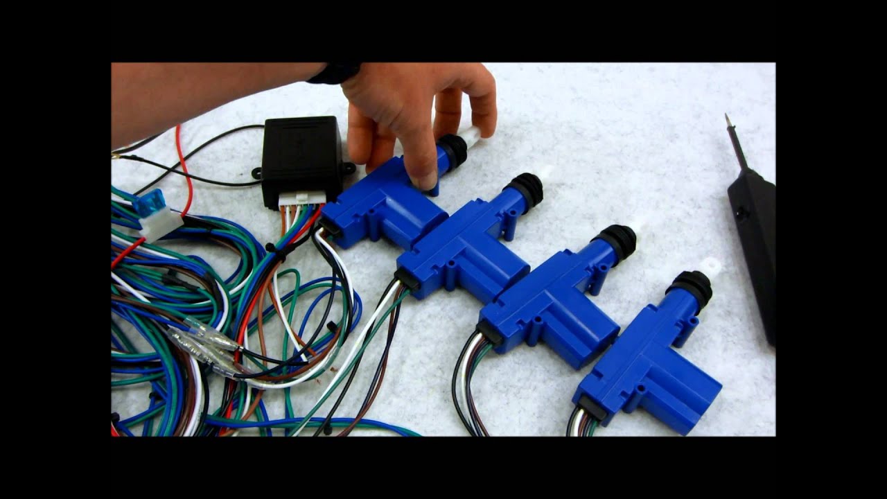
How Central Door Lock Actuators and Door Lock Relays Work In Detail.
www.lesscosales.com
www.lesscoelectronics.com
Here are some of the ways that you can unlock car doors:
With a key
By pressing the unlock button inside the car
By using the combination lock on the outside of the door
By pulling up the knob on the inside of th...
Cool thanks
 onyx kernel
What's the best way to route capacitive touch pads? I've done it like this ("encasing" every trace in GND)
 bright thistle
onyx kernel
What's the best way to route capacitive touch pads? I've done it like this ("enc...
bright thistle
onyx kernel
What's the best way to route capacitive touch pads? I've done it like this ("enc...
Watcha doin'? :3
onyx kernel
bright thistle
Watcha doin'? :3
a sort of smart light switch/smart home controller
 bright thistle
Nice, really interested in the caps part, I'm using them on my project as well, but the sparkfun ones I got are acting erratically
onyx kernel
This is what it looks like at the moment. Didn't work at all 🙂

Those yellow pads in the backgroud are peacess of aluminum foil connected to ground. Putting those things between the wires and the other components made it better but still not perfect
supple pollen
onyx kernel
What's the best way to route capacitive touch pads? I've done it like this ("enc...
Since they're measuring capacitance, the extra capacitance introduce by the nearby ground might be detrimental
onyx kernel
supple pollen
Since they're measuring capacitance, the extra capacitance introduce by the near...
thats what i thought while routing those pads 🙂
on the other had as far as i know theyre not actively being powered (there is no voltage on them) so there wouldn't be a capacitance between GND and the sensor pin?
supple pollen
I'm not entirely clear on how capacitive touch pins work, and there are at least a couple of different approaches. However, the capacitance to ground is always present, and when the pins are being read, there will be a signal of some sort on them.
 surreal tangle
I've only ever used capacitive touch on the ESP32 and I followed their design guide: https://github.com/espressif/esp-iot-solution/blob/release/v1.0/documents/touch_pad_solution/touch_sensor_design_en.md

GitHub
Espressif IoT Library. IoT Device Drivers, Documentations And Solutions. - espressif/esp-iot-solution
onyx kernel
well thanks for the help i think i got it
left grove
idk if this is helpful for you, but todbot from this server designed this with capacitive buttons: https://www.tindie.com/products/todbot/picotouch-capsense-midi-keyboard-for-raspi-pico/
onyx kernel
I've done mesh on the backside and finer mesh around the pads/traces with enough distance to the pads/traces now.
 onyx kernel
This is what it looks like at the moment. Didn't work at all 🙂
onyx kernel
onyx kernel
This is what it looks like at the moment. Didn't work at all 🙂
should work. at least its better than whatever this was xD
rigid plume
Would this work with an esp32-s3 WiFi/Bluetooth LNA for switching between IPX/Board antenna https://www.lcsc.com/product-detail/RF-Switches_Shenzhen-Fuman-Elec-FM1630C_C2857387.html
FM1630C Shenzhen Fuman Elec | C2857387 - LCSC Electronics
FM1630C Shenzhen Fuman Elec US$0.0309 - DFN-6(0.7x1.1) RF Switches ROHS datasheet, price, inventory C2857387
I'm not an RF expert, but I have made an board with it but it only seems I can scan for wifi networks but not transmit/connect
FM1630C Shenzhen Fuman Elec US$0.0309 - DFN-6(0.7x1.1) RF Switches ROHS datasheet, price, inventory C2857387
 cosmic charm
hi guys, recently i made custom esp32s3 board based on s3fn8, everthing work just fine except the wifi. I can scan WiFi around me and get decent rssi (around -37). But i cant connect to the network, i uploaded the same program to premade esp32 -s3 devboard and it work perfectly fine. Does anyone have solution?
supple pollen
Divide and conquer: there are a bunch of steps involved in joining a network, so what I do first is try to narrow down which steps succeeded.
torpid trout
(Just to satisfy my idle curiosity) I was trying to understand how self-driving piezo circuits work, in the context of this setup: http://kuzyatech.com/wp-content/uploads/2015/12/PC190096.jpg (only the feedback side of the buzzer is what I'm struggling to understand). For the three buzzer terminals, the middle one should be the feedback, and the other two main/ground. I can sort of understand most of it as:
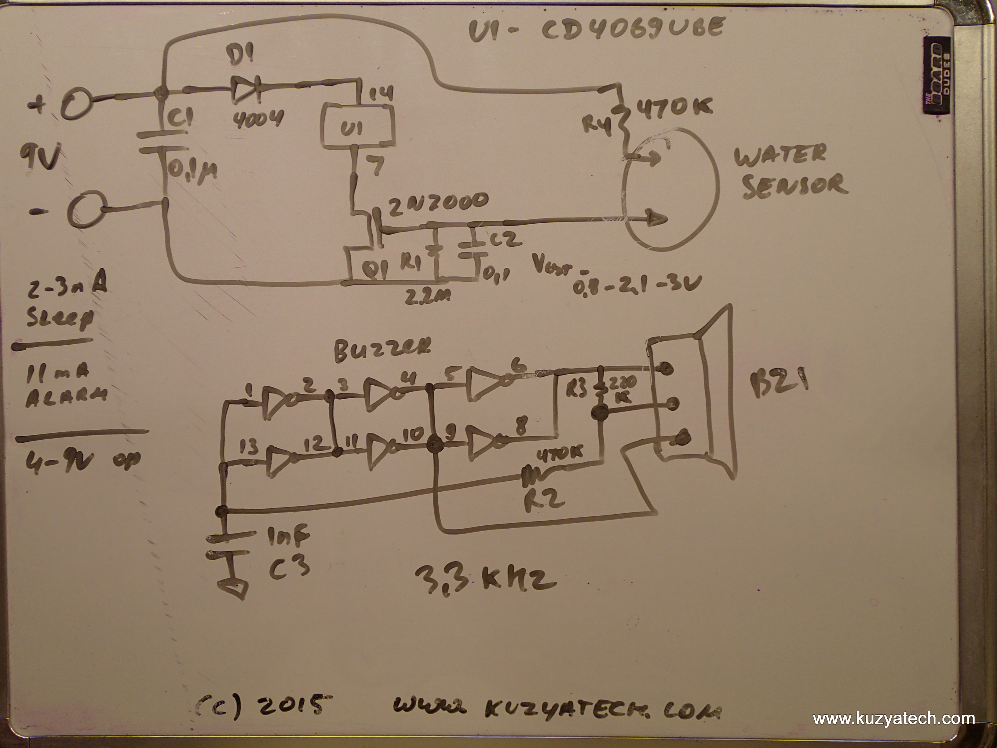
- the main/ground are connected to opposing sides of the inverter, so the voltage swing should be 2x of the logic level. So I'll ignore it for the rest.
- I'm understanding the feedback as going through a low-pass filter (R2/C3) and just using the chained inverters as buffer/amplifiers.
- It's the R3 between the feedback and the main that's puzzling me, and I must be misunderstanding something basic. What does it do?

 grim surge
As a sanity check before I try designing a whole optical keyboard PCB around it.
Does my breadboard setup make sense?
ESP32-S3 3v3 » 100Ω resistor » PT12-21C (photo transistor) » 10K resistor » IO8 and Ground.
- 100Ω resistor drops the current of the 3.3v down to 33 milliamp (below the 50 milliamp maximum the PT12-21C is rated for)
- 10K resistor seems good for filtering out noise whilst reliably picking up on pointing an IR LED at the sensor
grim surge
Actually.. I just came to the conclusion that it would take a lot of power to run as many matching IR12-21Cs... even if I seriously 'underpower' them.
Might just go back to the drawing board and use regular keys
supple pollen
torpid trout
(Just to satisfy my idle curiosity) I was trying to understand how self-driving ...
R3 might be a startup resistor to unbalance the circuit enough to get it to oscillate
celest umbra
@supple pollen more of a common sense question
i am acquiring these relays from my local electronics store

Omron MY4, 12 Volt DC, 5 Amp

we can see it says it can handle 5A

it is a 12VDC relay
but all the datasheets i find of it are saying it can only handle 3A


these are NoS coils
as in they are surplus and havent been used
supple pollen
What is NoS?
celest umbra
do you reckon it was a special order or something that got phased out
new old stock
supple pollen
Could be they got derated later
supple pollen
That's the conservative approach. It depends on how important lifetime/reliability is in your use case
celest umbra
sounds good thank you
torpid trout
supple pollen
R3 might be a startup resistor to unbalance the circuit enough to get it to osci...
thx for the tip (off to learn about this topic 🙂
cursive sentinel
supple pollen
What is NoS?
New Old Stock
Also for relays I'm not entirely sure why you'd bother getting NoS. There are often modern replacements. Some of them may even fit the socket.
celest umbra
cursive sentinel
Also for relays I'm not entirely sure why you'd bother getting NoS. There are of...
its fun to get parts from the surplus store
i could get a breakout arduino relay board or just a simple motor controller
but then it wouldnt be as fun
using transistors and relays and other switches and goods at the surplus store is a good challenge
i need to get in shape fast for all the electronics stuff i wanna do and my college classes arent that fast
so buying cheap parts and making them work in a complex manner does
cursive sentinel
celest umbra
its fun to get parts from the surplus store
I agree. Tektronix opens theirs every couple of weeks.
celest umbra
oh really
how do i get access to that
or do you just gotta wait till they arrive at a surplus store nearby
cursive sentinel
celest umbra
how do i get access to that
It's open to the public the first and third Thursday of every month from 2:00 to 4:00.
If you're in Beaverton I recommend it.
fickle patio
I'm learning about using MOSFETs to build a latching power switch, but I'm having trouble building one that works. This design is the first google result for "mosfet latch circuit," and the site describing it seems very confidant about its operation 😅
I have built the circuit (subsituting the dual mosfet with two seperate equivalent-ish P and N channel mosfets) and the latching behavior is working: a short press turns the circuit on, and a 3sec press turns it off.
My issue is the circuit's behavior when power is applied. This is supposed to be controlleld by a .1uf cap between the pmos gate and either VCC (for auto-on) or GND (for auto-off). In my circuit, the initial state seems mostly determined by whatever state I last put the switch in, rather than this jumper. For example, when I've held the button for three seconds to turn the latch off, the gate of the pmos is brought high. Even if i disconnect the batteries and reconnect them, this positive charge hangs around on the pmos gate regardless of where i have the auto on/off jumper set, and the circuit doesn't auto-on when I want it to.
Can anyone comment on the circuit, or suggest a resource for finding a latching circuit that doesn't rely on magic? This circuit comes from http://www.mosaic-industries.com/embedded-systems/microcontroller-projects/electronic-circuits/push-button-switch-turn-on/latching-toggle-power-switch

Application note for electronic latch circuits using logic gates and MOSFETs that detect a push button press to switch ON power to your embedded system. Because their MOSFET switches consume no current in the OFF state, these circuits are useful for battery powered portable instruments. A momentary button press turns a power MOSFET ON, and hol...
celest umbra
cursive sentinel
If you're in Beaverton I recommend it.
I'm in Orlando sadly
In Los Angeles it was extremely easy to find good gear or parts for cheap
Anything really
Here it's hard
cursive sentinel
fickle patio
I'm learning about using MOSFETs to build a latching power switch, but I'm havin...
Try redrawing the circuit with the battery disconnected in each switch state.
fickle patio
cursive sentinel
Try redrawing the circuit with the battery disconnected in each switch state.
Thanks for looking at my little problem 🙂 I'm not sure what you mean about redrawing the circuit.
astral sun
When I plug the rotary cnc into the 4 rotary encoder Pcb and use vin for vcc plugged into a micro key I get a usb-shutdown condition …. Anyone know if this rotary will work with the adafruit Pcb like this?
supple pollen
celest umbra
I'm in Orlando sadly
Skycraft is still around but they moved
torpid trout
supple pollen
R3 might be a startup resistor to unbalance the circuit enough to get it to osci...
Back on this - assuming R2/C3 is indeed intended as a low-pass filter - I'm confused about the cutoff. I thought it should be 1/(2pi470k*1n) which works out to 330 Hz, but I'm pretty sure the piezo device wants to work around 3.3KHz. I'm missing a zero somewhere
supple pollen
torpid trout
Back on this - assuming R2/C3 is indeed intended as a low-pass filter - I'm conf...
I don't think it's a filter, I think it's acting as a phase shift network
vast flume
Would this much flash usage cause me to run into a hardfault on an stm32?
 left grove
Why would flash usage run into any kind of runtime error at all? (or is your program writing to flash?) (I know pretty much nothing about stm32 in particular)
vast flume
I'm not sure
All I know is when I include certain code it crashes at this point
This function

Heres the defs for peek_next and read_next

Also the strange part is that this only happens when I am debugging. If I run without debugging there is no issue
split obsidian
Does anyone know of any multiple-transistor packages? Something like 8 2n2222 BJT transistors packaged up on a DIP or something? Just to simplify a BOM and soldering job? Searches keep pulling up Darlingtons which I don't think is what I'm looking for. More like a transistor array?
Something like this but without the "differential pair" section
(on and off my devices helping with kiddo, please @ me with any thoughts) 🙂

 hasty solar
anyone know of a pcb or similar all-in-one tool for controlling 12V/750mA power with a GPIO signal? i've been using this pcb but it recently shorted out, since it's only rated for about .6A: https://www.tindie.com/products/jeremycook/ez-fan2-tiny-raspberry-pi-fan-controller/
generally i'm just trying to avoid needing to spec and wire up the transistor+flyback diode+resistor myself

Tindie
EZ Fan2 is a tiny PCB for controlling small cooling fans or other motors
celest umbra
supple pollen
Skycraft is still around but they moved
im using them a lot right now
thank you
celest umbra
hasty solar
anyone know of a pcb or similar all-in-one tool for controlling 12V/750mA power ...
why not just spec it out
cheap
could also get something from here
sparkfun hasa decent selection of motor controllers
DC/Gearmotor Driver - and more...

Our wide selection of motor drivers, motor controllers, and servo controllers let you control your actuators with ease!
or here
inland jungle

Product Description: Input control voltage: 3.3V-12V Output voltage: 5-36V The board uses optical isolation and is completely separated from the 2-terminal voltage. The input is controlled by 2-pin control and the ground control can be directly connected to the control switch. Control current 1-5...
paper vale
hello. please how to add plated though holes in a footprint of a though hole component in Altium ?
supple pollen
vast flume
This function
You probably want <= for your comparison check. Duplicating your while clause with an if clause also seems silly. My usual approch is more like:
void ST_USB::readTo(char * data, char flag)
{
  char         ch;
  char *    bufptr;
  char *    bufend = data + USB_BUFFER_SIZE;

  for (bufptr = data; bufptr < bufend; ++bufptr) {
    ch = peek_next();

    if (ch == '\0' || ch == flag) {
      return;
    }

    bufptr = read_next();
  }
}