#help-with-linux-sbcs
1 messages · Page 28 of 1
 steady rose
then not sure why it's not working the other way. should be nominally the same.
seems like somehow things are being run as different users though
 novel mist
I think somethink like that.
I manage to localise the issue. I am using rgbmatrix library. IF I remove it it is works fine
https://github.com/hzeller/rpi-rgb-led-matrix

GitHub
Controlling up to three chains of 64x64, 32x32, 16x32 or similar RGB LED displays using Raspberry Pi GPIO - GitHub - hzeller/rpi-rgb-led-matrix: Controlling up to three chains of 64x64, 32x32, 16x3...
RGBMatrixOptions.drop_privileges = False
that was the solution! 🙂
 red zephyr
Hi all, any Linux/ALSA experts here? I'm using the 'MAX98357 I2S Class-D Mono Amp' on a Pi running Buster. I've got it all working with ALSA softvol as per the ALSA config & instructions here https://learn.adafruit.com/adafruit-max98357-i2s-class-d-mono-amp/raspberry-pi-usage
I can control the volume just fine in alsamixer but USB HID 'Consumer Control' (e.g. USB keyboard volume/mute keys) doesn't work, which I could really use for my project.
Any pointers appreciated. Thanks for reading!
 red mica
hey guys im@using an adafruit 64x32 display (Product number 2279) and im having an issue where when i plug it in i see the same pixels light up. I had wired it to my rpi and used rpi-rgb-led-matrix library to try and get it to say hello world but it just showed a bunch lf garbage. Now when I try, however, nothing happens and there is just a green line. also when i bought the product and plugged it in (5v 4a) it would create lines on its own and the display would glitch out despite having no input device plugged in. Is tyere any chance i got sent a display with a shorted board?? also, if this isnt the right thread to post in please lmk. the problem isnt with the rpi I just happen to be using one and i didnt see a thread for adafruit display panels in gsneral

 steady rose
looks like you're making the ribbon cable connections with individual jumper wires?

 proud parcel
Hi all, im darkan and I need some help with my raspberry pi and RPLidar S1. I ran a program from https://learn.adafruit.com/slamtec-rplidar-on-pi?view=all , and my error was called descriptor length mismatch. Can anyone help me? thanks in advance 😀 Attached is the image of the error code


Adafruit Learning System
Letting a Pi know what's around it.
 slender meadow
Hi All, having an issue that I did manage to solve, but then stripped everything and put it back together and seem to have lost my solution through forgetfulness. I am wiring a Hall Effect to a PI. I am getting nice square waves but the VPP is 12v instead of below 3.3v. If you reference the diagram, can someone tell me what I am doing wrong?
 red mica
steady rose
looks like you're making the ribbon cable connections with individual jumper wir...
red mica
steady rose
looks like you're making the ribbon cable connections with individual jumper wir...
yes but as you can see its not plugged in so why is there any display?? also what id wrong with jumper wires? i tested all the connections and i am just prototyping right now, i will solder once i get it working
i think theres water damage however cause i got something working earlier but i had the hub75 connection wired incorrectly. also before i even gave it any input there were a bunch of lines of pixels that would glitch around sporadically
but now it only shows the green line
red zephyr
Hi all any LinuxALSA experts here I m
 umbral sable
slender meadow
Hi All, having an issue that I did manage to solve, but then stripped everything...
umbral sable
slender meadow
Hi All, having an issue that I did manage to solve, but then stripped everything...
Normally I'd expect to see the 10k pull-up resistor going to the Pi's 3.3V power rail instead of to the 12V Hall-sensor supply. Is that something you can change or is it built inside the sensor itself?
 faint sparrow
General advice needed:
I make some hobby motor controllers in arduino currently, but have gotten my hands on some Pi Picos. I'd love to make a new program on one of those, hopefully as a python on Linux learning experience.
Would I be cutting corners to program in circuitpython or should I use a different platform for a more true experience?
 turbid rivet
faint sparrow
General advice needed:
I make some hobby motor controllers in arduino currently,...
turbid rivet
faint sparrow
General advice needed:
I make some hobby motor controllers in arduino currently,...
Circuitpython has its advantages and disadvantages as a platform. I wouldn't say it's a means of cutting corners, but it does offer a much more streamlined iteration process for a quick design. Depending on what you're trying to accomplish, Arduino or MicroPython would certainly offer other advantages, so there's no clear answer from a "general" standpoint.
faint sparrow
turbid rivet
Circuitpython has its advantages and disadvantages as a platform. I wouldn't say...
Apart from completing this project, the goal is to be able to write python programs in Linux in general.
turbid rivet
If you're building a device to interface with a Pi Pico as a controller of some sorts, I don't think any platform would be necessarily ill-suited. If you need access to low-level functions like interrupts, that would be a case for MicroPython/Arduino over CircuitPython.
On the other hand, if you want code that's easily ported to other boards, CircuitPython has its own distinct advantages there.
faint sparrow
I'll be controlling a brushless motor which is basically activated with a single input, there will be a few low side switches for some LEDs, a small SSD1306 I2C display and 5-6 buttons on this particular project. None of them probably require hardware interrupt.
I think circuitpython would be the quickest way for this project, but if the next one I make is for a weather station running on a Pi 4, will I have any useful experiences from programming this i circuitpython, you think?
 lost wolf
faint sparrow
I think circuitpython would be the quickest way for this project, but if the nex...
lost wolf
faint sparrow
I think circuitpython would be the quickest way for this project, but if the nex...
So, there's a compatibility layer for CircuitPython on Raspberry Pi, called Adafruit Blinka, that allows you to use CircuitPython libraries on RPi. Basically, you can use the same code from a microcontroller on a Pi, and have it work the same. So... anything you learn from the Pico project will definitely help you out on Pi.
faint sparrow
lost wolf
So, there's a compatibility layer for CircuitPython on Raspberry Pi, called Adaf...
Interesting, so that's what Blinka is.
Thanks for the explanation.
lost wolf
You're welcome!
turbid rivet
In my opinion, there's no such thing as an experience that ISN'T useful. Even if the code learned from one project doesn't get used in another, making the project will still offer an understanding of how certain things work (and sometimes how they don't) which becomes part of your experience for future projects.
faint sparrow
I can't really disagree with that.
Thanks, both of you for taking the time 🙂
lost wolf
faint sparrow
I can't really disagree with that.
Thanks, both of you for taking the time 🙂
You're entirely welcome. Keep us posted on how it goes, and definitely feel free to ask any questions as you go along. The #help-with-circuitpython channel will be best if you opt for using CircuitPython. This channel is more for RPi single board computer and Linux questions. If you opt for Arduino, #help-with-projects or #help-with-arduino are better options as well. Good luck!
faint sparrow
I'll keep that in mind 🙂
slender meadow
umbral sable
Normally I'd expect to see the 10k pull-up resistor going to the Pi's 3.3V power...
Hi @umbral sable, yeah that is something i can change. do I get rid of the Resistor between + and Signal then?
slender meadow
ok i switched the resistor around and got a nice VPP of around 2v
 brave nebula
red mica
yes but as you can see its not plugged in so why is there any display?? also wha...
brave nebula
red mica
yes but as you can see its not plugged in so why is there any display?? also wha...
I havent read all, but I see that if "sudo" is not used when invoking the module which displays the graphic if you are using the hzeller matrix library.
Is there a "list" of CircuitPython libraries I can import on a raspberry pi? Or, a list of libraries that wont work? I am using a RGB Matrix HAT with RTC, # 2345. I've used the hzeller libraries successfully along with 6 adafruit sensors(via blinka install).
Can I use labels? bitmaps? Fonts?
brave nebula
faint sparrow
I'll keep that in mind 🙂
Hey, I saw you flying in my front yard this morning!
faint sparrow
brave nebula
Hey, I saw you flying in my front yard this morning!
Hey hey, sorry for the silly alias. I use discord mostly for video games purposes, so that's why I have this name.
brave nebula
faint sparrow
Hey hey, sorry for the silly alias. I use discord mostly for video games purpose...
Not silly to me... I'm a squirrel...
faint sparrow
brave nebula
Not silly to me... I'm a squirrel...
Squirrels are very cool 🙂
brave nebula
faint sparrow
I'll be controlling a brushless motor which is basically activated with a single...
Circuit Python is the way to go. On your weather station, you merely must consider the type of display. Then proceed from there. I use a RGB Matrix 256 wide x 128 tall. I'm right now playing with a "weather" [whether] station.
faint sparrow
brave nebula
Circuit Python is the way to go. On your weather station, you merely must consid...
Thanks, I already started making the design for a small extension board for the pico and it will be programmed in Circuitpython.
I'll be using a SSD1306 I2C 0.96" display too, will be fun to make it work.
brave nebula
Got it.
faint sparrow
Thanks for your advice 🙂
brave nebula
is it a feather pico?
brave nebula
No problem. I was looking at the display to see if you could scroll it, but it looks like it will be too slow. It will be like you paint your weather info every 3 seconds or so.
faint sparrow
Display speed didn't really occur to me. This project is airsoft related, and I was thinking to add a bb counter, but maybe that won't make sense.
brave nebula

Adafruit Learning System
Build an internet-connected weather display with an RGB LED matrix
if John used dispio it should work
faint sparrow
Looks pretty cool 🙂
brave nebula
Your weather station will be neato when done... The hardest part is figuring what to display when.
faint sparrow
I hope so 🙂 Thanks.
 pearl rapids
My Pi's internet doesn't work after I ssh to it. It says it is connected, but I can't look anything up or install packages. What do I do?
 raven pine
i can't seem to use my pn532 over SPI, even though it worked fine over I2C
nfc list gives me this:
hasuki@raspberrypi:/dev $ sudo nfc-list
nfc-list uses libnfc 1.8.0
error   libnfc.driver.pn532_spi Unable to wait for SPI data. (RX)
pn53x_check_communication: Timeout
error   libnfc.driver.pn532_spi Unable to wait for SPI data. (RX)
nfc-list: ERROR: Unable to open NFC device: pn532_spi:/dev/spidev0.0:50000
Are you confident in your wiring to the SPI pins?
raven pine
about 5060% confident.


hasuki@raspberrypi:~/pn532-spi $ ls /dev/spidev0.*
/dev/spidev0.0  /dev/spidev0.1

those 00s are..a little concerning
steady rose
is this dip switch set for SPI? can't tell for sure from photo

 humble marsh
steady rose
is this dip switch set for SPI? can't tell for sure from photo
humble marsh
steady rose
is this dip switch set for SPI? can't tell for sure from photo
I cannot really tell either, but if they are slide switches, then they look "down" (off), some maybe it's set to HSU?
esp since 11 is not a valid combo, and they appear to be set the same?
turbid rivet
humble marsh
esp since 11 is not a valid combo, and they appear to be set the same?
The picture quality is super hard to tell, but I don't think that's set to 11. Since the lighter surface is usually the raised one in these images, it should be 10 or 01.
Though, on that note, @raven pine did you move the switch positions when you moved to SPI?
 zinc jackal
Always turn it up to 11...
 stray robin
Hello! I`am using a Power Boost 500 basic from adafruit and a li-po cell to power raspberry pi zero. While powering raspberry pi there is a hum noise and after few seconds the raspberry is shutting down. When i power raspberry pi from another source everything is ok. Do you know what the problem should be ? Thank you very much!
 opaque wagon
How big is the LiPo battery and how are the connections?
stray robin
opaque wagon
How big is the LiPo battery and how are the connections?
It is a 2600 mAh lipo battery. I connect the battery through adafruit jst conector and i power rpi from usb
opaque wagon
Hows the USB cable? Make sure it's not a super thin/cheap one and it's connected properly.
raven pine
turbid rivet
Though, on that note, <@208869516199854080> did you move the switch positions wh...
yep! it is set in SPI. still not working tho
opaque wagon
stray robin
Hello! I`am using a Power Boost 500 basic from adafruit and a li-po cell to powe...
I get the hum noise too - pretty sure it's coil noise
(I have one too, but I'm not powering a Pi - I'm powering a portable ESP32 project)
stray robin
opaque wagon
Hows the USB cable? Make sure it's not a super thin/cheap one and it's connected...
If i power rpi from laptop with usb everything is ok
opaque wagon
stray robin
If i power rpi from laptop with usb everything is ok
Typically, a laptop cannot supply enough current to power a Pi, so it will reset too. How are you determining that the Pi keeps shutting down?
stray robin
Should be a problem if the battery is now 3.7V ?
opaque wagon
Also is it fresh?
opaque wagon
stray robin
Should be a problem if the battery is now 3.7V ?
No, typical LiPo range for common ones is 4.2v to 3.2v - 3.7v is nominal voltage
stray robin
opaque wagon
Typically, a laptop cannot supply enough current to power a Pi, so it will reset...
Ia ok for pi zero
is*
Another thing, the raspberry is not really shutted down, after a few seconds the led is off and the current stay at 75mA
opaque wagon
stray robin
Another thing, the raspberry is not really shutted down, after a few seconds the...
Yes, this is normal as a Pi without extra hardware does not have any real power control - after shutting down it just sits there in low power mode, but still sipping power
stray robin
The problem is only with rpi zero. For rpi 4 it works good
raven pine
raven pine
yep! it is set in SPI. still not working tho
so i have found out that some of the headers aren't completely straight with the board--, would that be causing it

I might try resoldering tbh
 red knoll
That's not a great angle to evaluate the solder work, but it does look like at least one of the not fully seated pins may be a bad solder joint.
raven pine
 steady rose
yep, def worth trying to reflow those pins to see if it helps. looks like the pads did not get heated adequately, so solder clumped onto the pins.

that's more important than this minor misalignment

but could potentially fix both at same time - can reset pins while reflowing
raven pine
steady rose
yep, def worth trying to reflow those pins to see if it helps. looks like the pa...
alright, how do we reflow? I saw something about an oven but I'm not sure if that's right-
steady rose
don't add any more solder
just reheat with iron
and focus on getting heat on both pin and pad
raven pine
got it, I'll give it a shot

 raven pine
tried hooking it up anyway, and got the same thing:
hasuki@raspberrypi:~/spidev_test $ ./spidev_test -D /dev/spidev0.0
spi mode: 4
bits per word: 8
max speed: 500000 Hz (500 KHz)

00 00 00 00 00 00
00 00 00 00 00 00
00 00 00 00 00 00
00 00 00 00 00 00
00 00 00 00 00 00
00 00 00 00 00 00
00 00
hasuki@raspberrypi:~/spidev_test $
what i am assuming is its some sort of issue with the SPI connection..
would it be a good idea just to resolder?
 untold peak
raven pine
would it be a good idea just to resolder?
untold peak
raven pine
would it be a good idea just to resolder?
You probably don't need to resolder, but you should definitely try to reflow them again. Also reflow the ground and VCC pins, too. They don't look wonderful. It looks like you may be close to burning the board. Make sure your iron doesn't have too big of a tip and isn't set to too high of a temperature. See https://learn.adafruit.com/adafruit-guide-excellent-soldering
Also, Collin has an excellent video: https://learn.adafruit.com/collins-lab-soldering
untold peak
See the guide to excellent soldering I linked above. It's the same as the initial soldering, except don't add any solder. If you have flux, add flux to increase the heat transfer.
Here's an example I did earlier this week with an iron tip that was slightly too big, but they're pretty good.

Pin 35 could use a reflow, but it works fine.
raven pine
oh! oki oki got it, I'll give it a shot
untold peak
Watch the solder on the pins. When it turns nice and silvery it will flow around the pin and the pad. If you watch the Collin video, you'll see what I mean. The 25 second mark through 30 second mark really shows it.
faint sparrow
I get this error after plugging in the pico. Worked fine before. Anyone knows a fix?

I suspect my usb port is damaged although I may be wrong. Anyone knows if there is a USB D+ and D- on the raspberry pi pico outside the micro header
turbid rivet
faint sparrow
I get this error after plugging in the pico. Worked fine before. Anyone knows a ...
Try rebooting your PC or plugging it into a different one? USB issues are fairly common on Win10, not sure if it's necessarily Pico-specific.
faint sparrow
turbid rivet
Try rebooting your PC or plugging it into a different one? USB issues are fairly...
thanks for your reply. after fidling arround it started working again and I don't know why
no soldering required
 echo hare
hello everyone ,
ı have a oled screen , this screen have six pins. This pins names vcc,gnd,res,d0,d1,dc . I didnt work it. I try a lot of way. Please help me . How can ı work it
turbid rivet
echo hare
hello everyone ,
ı have a oled screen , this screen have six pins. This pins na...
What board are you connecting it to? Pi 3B/4?
turbid rivet
Could you send a picture of your display? Both sides, preferably.
echo hare

 echo hare
turbid rivet
Could you send a picture of your display? Both sides, preferably.
echo hare
turbid rivet
Could you send a picture of your display? Both sides, preferably.
do you look them
turbid rivet
echo hare
do you look them
Haha, I only check Discord between tasks at work, so sometimes I do get pulled away from conversations.
Hmm, that's not one I'm particularly familiar with, so I'm hesitant to give any definitive answers. Where did you buy this module from?
echo hare
in internet in turkey
turbid rivet
Do you have a link?
echo hare

https://www.direnc.net/
128x64 0.96 inç OLED Grafik Ekran 6 Pin SPI ürününü uygun fiyatı, hızlı kargo seçeneği ile 128x64 Grafik Lcd Display, Oled Lcd Display, Arduino Lcd Display kategorisinden online olarak Türkiye'nin en büyük elektronik komponent satış sitesi Direnc.net® 'ten hemen satın alabilirsiniz.
turbid rivet
Hmm, doesn't offer a lot of info, either.
For wiring, try the following based on https://learn.adafruit.com/monochrome-oled-breakouts/python-wiring:
VCC -> 3V3
GND -> GND
D0 --> MOSI
D1 --> MISO (not needed?)
RES -> RST
DC --> SCLK
For software setup, try following the guide to the next page?
turbid rivet
Does the display light up at all?
If it has power but no image, it could be the data pins are wired incorrectly. You can try wiring the RES pin to 3V3 or GND and see if any of those light up the backlight, at least. If the image appears but is totally garbled, it is possible there's a different chip with a different library requirement.
Honestly, it's hard to diagnose the issue when it comes to cheap displays with no documentation. If the displays are cheap enough and shipping costs aren't awful, I'd buy a display with a little more documentation.
 vocal lava
@hushed vortex Sorry to bother you. When I try and run some of the Python examples in the OpenSign examples directory, I get the error: AttributeError: 'OpenSign' object has no attribute 'sleep' - any idea what I might be doing wrong? I thought I installed all of the requirements
 hushed vortex
@vocal lava no bother. I forgot to update the examples after I removed the sleep function, which was just calling time.sleep().
vocal lava
got it, thanks!
hushed vortex
np
hushed vortex
vocal lava
got it, thanks!
I filed an issue. Thanks for letting me know.
 low marsh
Random, has anyone had issues with a USB3 hub on a pi zero w? I have a USB Serial device I can plug directly into the OTG, works fine, but lsusb doesn't see the device if I plug it in via the hub. It can, however, see 2 other devices on that hub, but never the serial device unless it's plugged directly into the OTG. I'm wondering if it's a USB3 thing? The hub is the only thing USB3 and USB3 is supposed to be fully reverse compatible with USB2, right?
umbral sable
Have you tried the serial device in different ports on the hub?
low marsh
yup, I tried it in port1, doesn't show up, plugged a different device into port1, that device shows up just fine, I've tried pi -> hub -> serial device on any port w/out anything else on the hub
I've tried 2 different USB hubs too
umbral sable
Not sure what's going on, but that's not expected. I'd suspect something might be physically wrong with the serial device's plug, like a pin just happens to make a connection on the OTG port but misses by a little bit on other ports on the hub.
low marsh
The serial device does get power and it works fine on my MacBook too
umbral sable
How about using the hub with your MacBook? That would eliminate any question about the Pi.
low marsh
yea, the serial device is micro-USB, I just tried 3 different cables and no difference; I plugged the hub into my macbook and it sees it just fine
like the serial device somehow knows it's not connected directly with the OTG and has issue with it, but it's fine going through the hub for my macbook
my PSU for the pi is 5V 1A, BTW; just tried 5.2V 1.8A; no diff
also, if I hotplug the serial device with 1 of the microUSB cables, the pi reboots, but the other cables don't do that
echo hare
how can ı remote control raspberry pi gpio using wifi ?
 opaque hill
echo hare
how can ı remote control raspberry pi gpio using wifi ?
opaque hill
echo hare
how can ı remote control raspberry pi gpio using wifi ?
You know raspberry pi makes a very good webserver. You can write backends with php or python or c and control pretty much want you want.
faint sparrow
Apparently there is a 9 Pi 4 4GB in stock. At 77$ locally in a brick store. Worth it for 22$ more than usual ?
Or should I wait for 8GB ?
humble marsh
faint sparrow
Apparently there is a 9 Pi 4 4GB in stock. At 77$ locally in a brick store. Wort...
4GB is fine for ordinary use. I've run desktop Windows systems with 4GB. If you need a Pi now, it seems like a choice. If you don't want to reward price-gougers, that's also a consideration.
turbid rivet
faint sparrow
Apparently there is a 9 Pi 4 4GB in stock. At 77$ locally in a brick store. Wort...
IIRC You're in Australia?
If so, 77 doesn't sound like a scalper price. I recall a lot of local electronics costs more simply for transportation costs and the like.
humble marsh
I think they are in Canada
 upbeat hull
Hello everyone.
Is there a way to use cyrcuit python on a raspberry without sudo?
I would like to run my application with gunicorn, but there is no way to run it with sudo
Thanks
steady rose
you really only need sudo to work around hardware access permissions
neopixels are the main culprit
or some network stuff, which may be why you need it for gunicorn?
upbeat hull
my python script is linked to a flask backend. And I would like to put it in nodemon with gunicorn
steady rose
do you typically need to run the flask/gunicorn app with sudo?
upbeat hull
I did not find the possibility to start gunicorn with sudo. With flask alone, it works fine
steady rose
upbeat hull
I did not find the possibility to start gunicorn with sudo. With flask alone, it...
are you using a circuitpython library that requires sudo?
upbeat hull
I use adafruit
steady rose
upbeat hull
I use adafruit
what circuitpython library?
 steady rose
ok. it's the neopixel library that is requiring running with sudo.
it's a hardware access permission
upbeat hull
ok so I have to find another solution to deploy my flask application
humble marsh
@steady rose is there a user group that has the right permissions for neopixel (as with i2c etc?)
steady rose
good question. i'm not acutally sure exactly which specific hardware interface it's bumping up against.
also wonder if setuid could be used
humble marsh
I would really like to get away from sudo stuff, because it confuses the pip installs as well, but it's a question...
 shut dirge
Anyone around to give me a hand with an adafruit tutorial that isn't working?
steady rose
shut dirge
Anyone around to give me a hand with an adafruit tutorial that isn't working?
which tutorial? what's not working?
shut dirge

Adafruit Learning System
How to control NeoPixel LEDs with Python on a Raspberry Pi!
This one
O actually turns out it's not from this my bad
shut dirge
im having trouble installing this https://github.com/bbx10/node-opc-server

GitHub
Open Pixel Control protocol for WS281x LEDs on Raspberry Pi - GitHub - bbx10/node-opc-server: Open Pixel Control protocol for WS281x LEDs on Raspberry Pi
shut dirge
shut dirge
im having trouble installing this https://github.com/bbx10/node-opc-server
turns out im just using the lib
 solid summit
im working on this repo that has pi pico tutorials and i finished the first one and im looking for some feedback https://github.com/AndrewSae/Raspberry-Pi-Pico-Project-Tutorials/tree/main/Led Blink

GitHub
Contribute to AndrewSae/Raspberry-Pi-Pico-Project-Tutorials development by creating an account on GitHub.
shut dirge
shut dirge
turns out im just using the lib
so it turns out that the node rpi-ws281x-native doesnt want to install at all
tried old node versions, old os versions
nothing
its so weird cuz in 2020 i had this working no problems
 hybrid heath
Does anyone know how much the Compute Module 4 weighs? It doesn't say in the datasheet.
If anyone has one and would be willing to put it on a kitchen scale or something I'd be very grateful lmao
 woeful shell
Can someone help me with this problem? "Unable to set line 17 to input"


 proud tapir
I connected the ribbon and gpio pins to display and raspberry pi but only the rainbow square shows up and then the screen is black

The leds on the raspberry pi are blinking like crazy
Wait
Now there is a static red light
I have lineage os downloaded
Can someone pls help
Now green. Light is blinking
Too
Should I take out the gpio pins and power separately?
turbid rivet
I’m not totally sure lineageOS is compatible with DSI screens, as I haven’t gotten mine to work yet, either. Have you verified the screen works with raspbian or other official OS?
proud tapir
I used an hdmi and a touchscreen usb with it and it worked with a larger screen
 agile depot
Im trying to use VLC in command line on Raspberry Pi OS Lite to stream a USB audio input through HTTP, how can I use the USB audio device as an input?
agile depot
apparently just adding alsa:// to the command works?
 civic rune
Does anyone know if the zero 2 would NOT work with the pi camera? I'm not seeing references to it in the docs
 unreal hamlet
civic rune
Does anyone know if the zero 2 would NOT work with the pi camera? I'm not seeing...
unreal hamlet
civic rune
Does anyone know if the zero 2 would NOT work with the pi camera? I'm not seeing...
Should be fine as long as you have the right cable (the connector is a little smaller on the pi zero so you need an adapter cable like this one: https://www.adafruit.com/product/5211)
 vast geyser
My apologies for a question that has probably been asked a zillion times, but does anyone know the order “blackout time” for raspberry pi’s? I’d really like to get an 8GB for some dev purposes, but my last order got voided, likely due to previous order (not voided, 2GB) a couple weeks before
humble marsh
vast geyser
My apologies for a question that has probably been asked a zillion times, but do...
It is just 1, indefinitely, at the moment: https://learn.adafruit.com/how-to-set-up-2-factor-authentication-on-adafruit/pi-2fa-f-a-q
_If I ordered a Pi of any kind, how long do I have to wait?
At this time it's 1 Pi unit, of any kind, per customer/location - when and if we can allocate more we will update these restrictions and provide a time when additional orders can be placed.
vast geyser
humble marsh
It is just 1, indefinitely, at the moment: <https://learn.adafruit.com/how-to-se...
Oh, I missed that. I shoulda waited for the 8GB I guess, instead of jumping the gun on the 2GB (like most, chronic pi shortage in my house!) Ah well, cross fingers digikey will fulfill my back order (lol, not holding my breath)
Ty very much
humble marsh
you're welcome!
vast geyser
LOL and minutes later rpilocator posts a message on this ….
https://twitter.com/rpilocator/status/1532007365993693199?s=21&t=JVKQl-LC7L8yqrudr5-Rtw

After getting a lot of questions from the community, I got in touch with @adafruit asking them to clarify their policy on limits for buying Pi boards. They just informed me they updated their FAQ with more details. Please read this. 1/n
https://t.co/QQ9niSbBcg
 Twitter
·
Twitter
·
That you, dan? 😄
(Heh, doesn’t match the pic, but you are both very helpful!)
humble marsh
not me, it's a coincidence, but I am chatting with the right person about making sure I understand and that it's clear everywhere
vast geyser
Heh, back to my I2C to neopixel board so my pi can set a few neopixels…
humble marsh
FAQ updated for clarity:
If I ordered a Pi of any kind, how long do I have to wait?
At this time it's 1 Pi unit, of any kind, per customer/location - when and if we can allocate more we will update these restrictions and provide a time when additional orders can be placed. Another order cannot be placed until we can allocate more.
 glass yew
This is probably a trivial question, but is it ok to use a RPi 4 power block on a RPi 3B+ ? I know its not recommended to use a 3 PS on a RPi 4 ..
vast geyser
It’s the wrong connector. So, at minimum, you’d need usb-C to micro usb. Not sure if the power supply is sensing or not.
turbid rivet
glass yew
This is probably a trivial question, but is it ok to use a RPi 4 power block on ...
Depends on usage. If you're just setting up a bare Pi, it's fine, but I wouldn't say it's ideal for long term use with a project. It's only short about half an amp of current, so it should be okay for temporary use with a light load.
Oh, wait that's for Pi 4 with 3B supply. Pi 4 supplies are fine with 3B, given the necessary adapter.
 celest flare
Is anyone familiar with these hammer in header pins? I bought it cheap on Amazon. I didn't notice it requires a jig that costs double the item. Can I get away with not using the jig?
 glass yew
turbid rivet
Oh, wait that's for Pi 4 with 3B supply. Pi 4 supplies are fine with 3B, given t...
glass yew
turbid rivet
Oh, wait that's for Pi 4 with 3B supply. Pi 4 supplies are fine with 3B, given t...
got it! Thanks ..
humble marsh
celest flare
Is anyone familiar with these hammer in header pins? I bought it cheap on Amazon...
read our product description: https://www.adafruit.com/product/3662

If your soldering isn't quite up to scratch, or you just don't own a soldering iron yet, then these nifty hammer headers from Pimoroni might be just what you ...
maybe you could make a jig out of popsicle sticks or similar
turbid rivet
Wait, @humble marsh you guys sell a jig. https://www.adafruit.com/product/3413

If your soldering isn't quite up to scratch, or you just don't own a soldering iron yet, then these nifty hammer headers from Pimoroni might be just what you need. They come in ...
Oh, double the item. I see.
turbid rivet
It's honestly not that expensive, and you could technically hammer with any hard flat surface if you're careful
celest flare
I do own a soldering iron. I wish I had read the fine print, lol.
humble marsh
maybe you can squeeze them with pliers and just solder 🙂
celest flare
I think you are right. Thanks!
 boreal zenith
Can I check sensor temperature on rpi pico using circuitpython??
steady rose
what temperature sensor?
humble marsh
microcontroller.cpu.temperature is implemented on RP2040
 tired marsh
so it's an analog sensor on GPIO 4
tired marsh
import analogio
import board
sensor_temp = analogio.AnalogIn(board.GP4)
print(sensor_temp.value)
 tired marsh
it's the pin
humble marsh
boreal zenith
sensor_temp = machine.ADC(4)
so do
import microcontroller
...
print(microcontroller.cpu.temperature)
oh no it's not
humble marsh
same idea as the micropython code
tired marsh
I never used ADC on MP, I didn't think it would be that confusing
humble marsh
I think the argument for machine.ADC() may mean different things on different ports
that is more MP style; the API caters to the port
tired marsh
see, I read adc = ADC(pin) in the example, but it acts differently if the argument is an int or a pin instance
 hot oar
Hi all! Does anyone know of a way to connect a 40 pin flexible flat DSI cable to a Raspberry Pi 3 B+? I know the DSI port on Pi is 15 pins only so anyone have an idea of a 40 pin to 15 pin converter? Is that even a thing?
umbral sable
Are you sure that what you have is a DSI cable? That's a lot of pins for that protocol. It might be a parallel TFT interface instead.
turbid rivet
DSI is not a standardized cable format either, so you’ll have to verify that your DSI display is designed for the raspberry pi. Many MIPI DSI displays are taken out of old phones and not directly compatible with the raspberry pi DSI connector.
Though 40 pin does sound more like a Dot clock TFT than a DSI display, as most DSI displays fall in a range of 15-24 pins iirc
faint sparrow
can i just power the pi at this point?

need to test if the display works before the return window close, it's connected with the ribbon cable at the left.
black(GND)/red wires(3.3V) are to connect the fan according to the instructions, so doesn't seem necessary just for testing the display
and I expect the ribbon cable isn't just for display but also has a gnd and power pin
zinc jackal
No idea on the issue itself, but reseat that ribbon cable..
faint sparrow
reseat? why?
turbid rivet
If the blue tab is showing, it might not be fully inserted.
faint sparrow
oh I see.. I don't even know how that connector works, like lock/unlock it etc...
and apparently the adapter board need its power supply too so I guess I'll have to unscrew everything if I want to test it
I thought the red and black wires were for a fan but apparently they are to power the pi from the adapter
hum they are for the fan in the instruction.... anyway what is the name of the connector so I can out how to lock/unlock it ?
turbid rivet
Other thing to check that’s not shown in the picture, is to make sure you have an SD card with an OS installed in the pi. Not all operating systems support DSI displays either, so raspberry pi OS is probably the safest option to test.
faint sparrow
yeah in it there is a 32gb raspbi card I just burned and tested for a couple fo days directly on a computer screen and added some packages/updated it
it's really the connector that has a sort of black tab that come out that I have no idea how it works
turbid rivet
Name? Probably something like a ZIF (zero insertion force) connector. There should be a tab that pulls out to release the cable, and pushes in to “lock.” They are a bit more fragile than the metal USB or HDMI ports you’re used to, so be gentle with them.
faint sparrow
the blue part was probably visible because I don't know how to lock it pack
seems fine now? blue thing is higher than the connector metal can show the other side if you want seems locked in and secure

I'm a bit confused because official instructions wants me to use the red/black jumper wires to attach the power the pi while in this it's the fan that use those jumper wires and the display and pi are connected from the pi power supply with a splitter
 turbid rivet
Are you mixing up two different sets of instructions? What kind of display is this?
faint sparrow
I'm trying not to mix them but the instructions for the enclosure are far from complete, like froem one pic to another there is an additional part installed with no explanation how what screws to use to put it on, what orientation etc.
It's the official 7" pi display with a smartpi touch pro (instructions: https://cdn.shopify.com/s/files/1/0793/8029/files/touch_pro_assembly_instructions.pdf?v=1640377735 product page: https://smarticase.com/products/smartipi-touch-pro ) and the instructions for the official display here: https://howchoo.com/pi/raspberry-pi-touchscreen-setup
so I'm just checking to double-check that what they want me to do is correct
I expected clear instructions like you get for assembling furniture with identified parts but the instructions are a bit difficult for me. Like I wish they had explained what connector it was and how to lock/unlock it etc
turbid rivet
Ehh, either should work. I'd just follow the instructions the case gives you and see where it takes you.
The splitter suggests the case maker took some extra effort to clean up the wiring the original display used, which I personally think is a much needed modification. While DSI displays can technically be powered over its cable, it's still much better to have separate power lines into each from the supply.
The connector should be pretty straightforward. The black tab should be flush with the white connector body in its locked state, and you should feel a slight click when it's fully locked.

To unlock, just pull on both sides of the black tab. Be careful doing this, though, as it also happens to be the most common way these things break.
faint sparrow
with the name you gave me I was able to find a video that explain it (on an ssd)
turbid rivet
faint sparrow
yeah I was careful, I saw there seemed to be a tab and if it wasn't being inserted there must be something wrong so I asked at my makerspace
Unless I know a connector is just messing with me for no reason (ie: like USB/HDMI) I'm careful and gentle 😄
USB are notorious for you plug them and it's always 100% the wrong side first, then you turn it 180o and it still wont connect
then you check inside to see which side, still doesn't want to go in then you force it in a bit because it's obviously messing with your sanity 🤣
faint sparrow
finally only hint i did a bad job asaembling it is this thing between the official pi screen and the case

and the electrical tape to hold the nut on the other side...

 devout anchor
I'm having some serial communication problems with a MetroM4 microcontroller that I haven't been able to resolve. I have the M4 set to use the console and data connections. I log the console to a text file with the screen command, and the data connection is used for the pySerial connection. At some point the connection gets interrupted and I'm not able to recover without a reboot of the RPi.
I've tried to catch the exception in a try-except construct which will close and reopen the serial connection, but I'm not even seeing that the device (/dev/ttyACM1) exists. This is where I'm getting stuck rebooting rather than gracefully recovering.
Traceback for one of the crashes.
 steady rose
please don't ask in multiple channels
faint sparrow
I think the microsd card or the unit to read it on my rpi4b is defective or something
faint sparrow
dont understand why it wont clip
 unborn hazel
hi im new to raspberry pi and trying to create a project using thermal camera either (the MLX90640 or lepton 3.5) which can be coded in python. May i know if there is any good guide out there for these thermal cameras that i can refer to? I know of the guide for MLX90640 from makersportal but thats all i can find. For the lepton camera there doesn't seem to have any guide in python.
unborn hazel
unborn hazel
hi im new to raspberry pi and trying to create a project using thermal camera ei...
I understand that there is others like AMG8833 but im looking for a higher resolution
unborn hazel
unborn hazel
hi im new to raspberry pi and trying to create a project using thermal camera ei...
I would like to generate a heatmap through that too, is there any guide for that too?
lost wolf
unborn hazel
hi im new to raspberry pi and trying to create a project using thermal camera ei...
I've never heard oft he Lepton, so I can't help you there. We have a guide on using the MLX though. https://learn.adafruit.com/adafruit-mlx90640-ir-thermal-camera/python-circuitpython
I'm not sure whether you can adapt this code to work on RPi. https://learn.adafruit.com/adafruit-mlx90640-ir-thermal-camera/circuitpython-thermal-camera
 lucid nebula
Bringing this back up again if anyone is able to help me
Images on the errors I received as a reference:

 faint sparrow
unborn hazel
hi im new to raspberry pi and trying to create a project using thermal camera ei...
faint sparrow
unborn hazel
hi im new to raspberry pi and trying to create a project using thermal camera ei...

GitHub
Quick and dirty pure python library for interfacing with FLIR lepton - GitHub - groupgets/pylepton: Quick and dirty pure python library for interfacing with FLIR lepton
faint sparrow
unborn hazel
hi im new to raspberry pi and trying to create a project using thermal camera ei...
for connections: https://github.com/groupgets/LeptonModule/wiki

GitHub
Code for getting started with the FLIR Lepton breakout board - Home · groupgets/LeptonModule Wiki
faint sparrow
do I actually need heatsink/fan for rapsberri pi 4b+ with a case?
My temperature laser says it heat to 50oC
doesn't seem bad
civic rune
I'd use the on-board thermistor
It all depends on what you're doing with it
Having it on there and not using isn't a problem
faint sparrow
Yesterday I was just installing stuff but I bought it for a camera/IR camera(FLIR)/LIDAR capability
so probably fairly intensive
zinc jackal
I got myself a heatsink for the Pi Zero 2 W, just because it was feeling a little too warm to touch at full pelt.
...and I wanted to play with overclocking it. 😁
faint sparrow
I don't even remember where most of my electronics are.... 😦
All I know are my MCUs and my Pis (arduino uno, mega 2560, pi pico, 4x qt py esp32-s2 and one esp82676 in d1 micro form factor) and pi 2b+ and pi 4b 8GB
unborn hazel
faint sparrow
https://github.com/groupgets/pylepton
Hi thanks for the library, is there a way to create a heat map and extract the raw temperature?
And also have anyone tried the openmv cam h7 with lepton 3.5 connected to Rpi? I saw some ppl trying it out on YouTube and it is a easier way if I just wan to create a heat map and extract the raw temperature? It supports tensor flow lite as well where I can ML model.
unborn hazel
unborn hazel
And also have anyone tried the openmv cam h7 with lepton 3.5 connected to Rpi? I...
Create my own ML model*
lucid nebula
lucid nebula
Images on the errors I received as a reference:
If anyone has any ideas what I start with, let me know
 night sail
It's the other way around; you're getting that error because the Pi is disconnected.
Start checking things like your DHCP settings. If you've setup port forwarding to SSH, it could be getting attacked; ceasing use of the Pi user could help fix that
lucid nebula
night sail
It's the other way around; you're getting that error because the Pi is disconnec...
How do I check my DHCP?
night sail
lucid nebula
How do I check my DHCP?
it'll be in the networking section on the Pi, and in your router/modern or however you're getting internet
lucid nebula
night sail
it'll be in the networking section on the Pi, and in your router/modern or howev...
Is there a guide?
night sail
depends on your modem/router on that side.
There are hundreds of guides for Pi networking stuff, without knowing what you've done so far it's hard to point to any specific one in general.
https://www.mathworks.com/help/supportpkg/raspberrypi/ug/configure-network-settings-of-raspberry-pi-hardware.html
This is one that pops up when I Google for it
Configure the network settings of your Raspberry Pi hardware.
night sail
lucid nebula
Is there a guide?
also it's just my assumption you've lost internet on the pi, but what happens if you try to ping 8.8.8.8?
lucid nebula
night sail
depends on your modem/router on that side.
There are hundreds of guides for Pi n...
I haven't done anything because idk what to do as a start
night sail
lucid nebula
I haven't done anything because idk what to do as a start
How did you initially get connected to the internet and how do you restore the connection when it drops?
lucid nebula
night sail
also it's just my assumption you've lost internet on the pi, but what happens if...
Destination Host Unreachable
lucid nebula
night sail
How did you initially get connected to the internet and how do you restore the c...
WiFi and I just reboot it
 bronze dock
heya! hit a mental roadblock with my project. hoping talking out loud will help, and would love a nudge in the right direction since i tend to make things overly complicated...
i have an arduino controlling a stepper and a servo. goal is to point at mars, the space station, etc etc. i can send it data from my pi over usb/serial to tell it where to point.... next challenge is to grab the data from the internet, using JPL's Horizons system. seems easy enough to get the data i need using http get/post requests using that...
i want to make it portable, so it needs to use my iphone for the internet connection, no prob ill just setup a hotspot. also want to control it from an app. seems like apple makes that nearly impossible for a hobbyist, so im thinking a webapp. ill use the pi to serve up a webpage i can use to control things. select the orbital body from a list, it will fetch the data from the internet, and tell the arduino to point at it
i guess my mental block comes from the 2 connections. i want to connect to my iphone's hotspot, and serve up a local-only webpage for control. i also want to be able to make http requests over the public internet. is that possible over a single wifi connection? also im a total noob at webapps, and there are SO many to choose from. any advice where to start / what to read up on?
all my code is C, but im happy to dabble in sumn else to get this working, just for fun/learning after all, and kinda think i have to in order to make a webpage. goal is to serve up a page with a list and a button. select "Mars, #472", click "Go"... pass #472 to my C program, which makes a http get request to a website, and returns 2 floats, which i do some math on, then pass 2 int's to the arduino over serial
 wheat rain
I installed Bullseye Lite (terminal only) on a Pi Zero 2W. How do I get WiFi working? Seems like they expect a wired ethernet connection for setup.
wheat rain
bronze dock
i guess my mental block comes from the 2 connections. i want to connect to my i...
Should work fine. Use a web browser on the Pi to get the web service working, then add the arduino stuff. Your iphone hotspot will relay the requests to the public internet for you.
turbid rivet
wheat rain
I installed Bullseye Lite (terminal only) on a Pi Zero 2W. How do I get WiFi wor...
If you can pull out the SD card and load it up from another PC, you should be able to edit wpa_supplicant.conf with your SSID and password?
 sacred oar
wheat rain
I installed Bullseye Lite (terminal only) on a Pi Zero 2W. How do I get WiFi wor...
sacred oar
wheat rain
I installed Bullseye Lite (terminal only) on a Pi Zero 2W. How do I get WiFi wor...
@wheat rain I think the easiest way may be to do it through raspi-config https://raspberrytips.com/raspberry-pi-wifi-setup/
Also yeah what @turbid rivet said should work too
wheat rain
I think raspi-config worked, but I had to run sudo ip link set wlan0 up to get it to actually connect.
sacred oar
Ah ok
 outer jetty
Hello I have this raspberry pi model 4 I tried to connect it via HDMI cable with adapter it was working and now it's gone (happened just after plugging HDMI cable probably crappy cable shorted it) just the red led is on the MXL7704-P4 chip is getting too hot also I measured the pins 5V is stable but 3.3V pins have like 0.74 Volt's on them also Pi makes a little buzzing sound please don't tell me the CPU is burned just the voltage regulator

and about repairs I cannot find replacement for model MXL7704-P4 just R3 available
need help thanks
 outer jetty
I hope its just that
 reef hawk
hi i need some help with my pi project
civic rune
Heya, usually folks around here suggest just laying out your issue so everyone can take a look. Odds are you can find someone who knows about your issue
 fickle rose
Something eerily similar happened to me. I was updating my pi 4 and left it connected to a tv then I walked away 30 minutes later i come back and it’s dead. 3.3v rail reading 1.8v and 1.8v rail is dead
sacred oar
fickle rose
Something eerily similar happened to me. I was updating my pi 4 and left it conn...
Have you checked the raspberry pi forums? If you both had this same issue it's possible it's a recurring thing and if it's a manufacturer defect they may have some program for replacement
outer jetty
fickle rose
Something eerily similar happened to me. I was updating my pi 4 and left it conn...
I checked the voltage and short circuits so yes PCIM chip is fried
no VDD_CORE voltage also
I'll get the replacement
Idk how to program it tho I'll try
outer jetty
sacred oar
Have you checked the raspberry pi forums? If you both had this same issue it's p...
I checked some of them and the same issue happens when you short 3.3V and 5V pins
sacred oar
Good to know
outer jetty
outer jetty
https://forums.raspberrypi.com/viewtopic.php?t=314996
also this
fickle rose
I’ve had that pi for 2 years so i think the warranty has expired
fickle rose
 hard pike
if it's getting too hot
hard pike
if it's getting too hot
My PMIC chip never got above ~35c for long periods so heat might not be the problem
hard pike
I was saying PMIC might have failed if it was hot and not reporting 3.3V on that rail.
which is what was mentioned. so idk
outer jetty
fickle rose
Something eerily similar happened to me. I was updating my pi 4 and left it conn...
hey about this I also plugged it to my TV and this happened
While back I encountered some sparks when connecting to TV HDMI ports with my laptop
maybe that caused it
 median heath
Hello guys. I am new to the working with raspberry pi and I wonder how is the best way to write programs and flush it into SD card? I am currently working on a project with raspberry pi zero and the goal is use LDC display and RF communications with a transceiver.
fickle rose
median heath
Hello guys. I am new to the working with raspberry pi and I wonder how is the be...
Raspberry pi imager
Here is a link https://www.raspberrypi.com/software/
Raspberry Pi
From industries large and small, to the kitchen table tinkerer, to the classroom coder, we make computing accessible and affordable for everybody.
median heath
fickle rose
Raspberry pi imager
Yes I already flushed the SD card with that. I have a hard time to understand best way to write the code and test it right away. Kind like with Arduino IDE...
fickle rose
Use python
Or more specifically use mu editor
It’s a very easy to use python ide that lets you write and test python code
median heath
And I write it on my pc and then upload to raspberry SD card?
fickle rose
Yes
median heath
that is what I needed to know. I did not undertood the workflow of programing...
fickle rose
If you put it on the drive named “boot” the python file will appear in “/boot/“ on the pi
median heath
Ok. I will try it out. Thank you for the help @fickle rose 😊
median heath
fickle rose
If you need more help just ask
I think I will need more help in future 😅
fickle rose
Pro tip:the adafruit guides on stuff have example code that you can use
sacred oar
median heath
I think I will need more help in future 😅
Is there any reason you don't just edit the code on the pi itself? Like if you put raspbian on it you've got a full graphical environment and even if you don't have an external display, keyboard, and mouse, you can still use VNC. Or if you put raspbian lite on it you can just ssh into it
If you aren't sure how to do that I can recommend you some guides. When I was in high school I used my Pi a lot since we couldn't install many programming things onto our school computers, and I found VNC and SSH to work really well (oh and also there's a way to connect your pi to internet over a usb cable connected to your computer, this took me a bit to figure out but was by far my fav way of doing it)
And even if your computer doesn't have internet, you can still connect to the Pi. I found that really really useful
 topaz ginkgo
Any pointers on sourcing pi zero?
zinc jackal
topaz ginkgo
Any pointers on sourcing pi zero?
Sign up for notification emails on all the retailers.
It's all utter jank right now.
 gloomy steppe
hey guys, i'm chasing some help adding in wifi to my rp2040 macropad. Looking to offload this to the esp32 device (https://www.adafruit.com/product/4201) which i believe needs to be connected through I2C, but unsure on the specifics on this and hoping someone can guide me on this or if there is a better option

Give your plain ol' microcontroller project a lift with the Adafruit AirLift - a breakout board that lets you use the powerful ESP32 as a WiFi co-processor. You probably have your ...
turbid rivet
gloomy steppe
hey guys, i'm chasing some help adding in wifi to my rp2040 macropad. Looking to...
The airlift is designed to work with spi, not I2C, so it may be hard to interface that with the macro pad. If you plan to use I2C you’ll need to generate custom firmware to accept your own commands as far as Wi-Fi is concerned.
It might make more sense to use an esp32 feather for easier development at that point.
gloomy steppe
Thanks @turbid rivet, so would the feather connect to the macropad via i2c? Or is it meant to replace to rp2040? Sry for the rookie questions. Just trying to find the most logical way to get wifi on this macro pad
turbid rivet
I thought about this a while back but haven’t actually developed anything yet. I2C would probably be the easiest way, but it would restrict your Wi-Fi to doing a fairly limited set of tasks. UART from the macropad’s qt connector is another option, but offers its own set of challenges.
It might not be too hard to build a macro pad with an esp32-s2 if you want to use it as a smart home controller, but the cost of a whole new set of hardware isn’t trivial, either.
fickle rose
topaz ginkgo
Any pointers on sourcing pi zero?
It can tell you where the pi is in stock and when it was last in stock
The raspberry pi 4 2gb is in stock on adafruit
 bitter pecan
I messed up while trying to hook up a picoprobe and got some magic smoke... I've identified the burned thing as the shottsky diode across VBUS and VSYS but the weird thing is the pico still seems to be working completely fine... I measured the voltage drop across it compared to another working one and its 0.2 volts vs 0.22 volts... do I have anything to really worry about with this? (Can't remember but its possible I hooked up an external 4.2v to somewhere, other than that I was trying to connect the power rails on the picos and clearly missed or something)
 bitter pecan
okay I probably had an external power source but also yeah this is still pretty fine
 fickle rose
Looking at the schematic if the pico is plugged into usb and you power VSYS with the fried shottky diode it might back power the usb port and possibly damage the computer
bitter pecan
tbh testing with a multimeter it seems the same as others but probably not with actual load
fickle rose
I would still replace it just to be safe
 amber shale
anyone know if there's videocore vi datasheet? I know theres one for iv
stray robin
hello! does anyone know where should I find more about raspberry pi zero 2w antenna ?
 heavy pendant
Hi, please how can I setup VS code for pico development on MacOS ?
amber shale
heavy pendant
Hi, please how can I setup VS code for pico development on MacOS ?
https://www.okdo.com/getting-started/get-started-with-raspberry-pi-pico-visual-studio-code/#h-1-toolchain-installation-toc For the apt stuff theres prob homebrew equivalents

This guide will take you through the steps to connect the Pico and Raspberry Pi using the SWD interface and setup a Visual Studio Code development environment so you can explore the sample code to kick-start your C/C++ Pico programming.
 dusky steppe
Can I send a gpio signal from a pi 3 to a pico
hard pike
dusky steppe
Can I send a gpio signal from a pi 3 to a pico
I don’t see why not
You’ll want to look up interrupts for C language based coding or asyncio for circuitpython
dusky steppe
I'm using circuitpython I'm not needed anything special I'm using the pico as a counter. The pi will occasionally send simple on off signal. I don't know how to wire it. I have the programs set up just not the wiring bit.
heavy pendant
amber shale
https://www.okdo.com/getting-started/get-started-with-raspberry-pi-pico-visual-s...
Thanks 🙏
hard pike
dusky steppe
I'm using circuitpython I'm not needed anything special I'm using the pico as a ...
I would connect ground of both devices together and then connect your signals. That should be good enough since both are 3.3V logic.
dusky steppe
Ok
 long pike
Does anyone have success with setting up both SPI0 and SPI1 to use with two devices, in my case a Display and a MCP3008? I've followed the adafruit tutorials but "ls -l /dev/spi*" only shows /dev/spidev0.0 and /dev/spidev0.1
civic rune
I don't know for sure that you need to do that? What's your goal? Because chip select exists for what I think you're doing.
long pike
I guess I'm just confused - can the MISO, MOSI and SCLK Pins be connected to multiple devices at the same time?
civic rune
Yes!
It's neat
You use the Chip Select (older term that is still used sometimes is Slave Select) lines to accomplish it
long pike
Thanks, that's been going over my head so far!
How do i select my newly created CS Pin in my code though? So far the standard is "cs=digitalio.DigitalInOut(board.D5)" - which pattern does "board" follow? Sorry for the many questions
civic rune
Don't apologize! That's what the server is for
I think it would be cs = board.D5 in the constructor and then the class would handle initialization
But I'm cleaning my home and I don't have the api in front of me
So I may be wrong
long pike
I guess I'll just have to try it out tomorrow and see what happens! Thanks for your time
civic rune
Good luck and happy to
 arctic seal
Hello. I'm new to both python and hardware controlling (but not to coding). I'm trying to get a raspberry pi to talk to 2 led strips and control them separately based on user feedback. Trying to do it with Adafruit CircuitPython NeoPixel. I can control each strip individually, no problem, but when I try to do both at the same time, I intermittently get
"Raspberry Pi neopixel support is for one strip only!"
Is there a way to do this? Or should I just connect my led strips, and control each half separately?
fickle rose
arctic seal
Hello. I'm new to both python and hardware controlling (but not to coding). I'm ...
i'm not a expert but i think the reason you can only use one strip is that it's hard bit-banging the neopixel signal and the raspberry pi can't handle 2 strips
dotstars might work
they control almost the same in python so no major code modifications needed to switch from neopixels to dotstars
arctic seal
fickle rose
i'm not a expert but i think the reason you can only use one strip is that it's ...
Ok, so it's not just me, it is not possible to reliably control multiple led strips with this setup?
civic rune
I think not
fickle rose
you could also chain the dout of the first strip into the din of the second along with a bit of coding if you don't want to get new strips
civic rune
That's a good idea
arctic seal
Thanks, I'll give that a try.
lucid nebula
How do I clone a git into a folder?
 pine flame
Hello guys! I'm trying to compile the blink example for the raspberry pico but for some reason cmake throws this error
[100%] Built target elf2uf2
[  0%] No install step for 'ELF2UF2Build'
[  0%] Completed 'ELF2UF2Build'
[  0%] Built target ELF2UF2Build
[  0%] Linking CXX executable blink.elf
AR10B2~1.EXE: error: ´╗┐CMakeFiles/blink.dir/blink.c.obj: No such file or directory
NMAKE : fatal error U1077: 'C:\PROGRA~2\GNUARM~1\102021~1.10\bin\AR10B2~1.EXE' : return code '0x1'
Stop.
NMAKE : fatal error U1077: '"C:\Program Files\Microsoft Visual Studio\2022\Community\VC\Tools\MSVC\14.32.31326\bin\HostX86\x86\nmake.exe"' : return code '0x2'
Stop.
NMAKE : fatal error U1077: '"C:\Program Files\Microsoft Visual Studio\2022\Community\VC\Tools\MSVC\14.32.31326\bin\HostX86\x86\nmake.exe"' : return code '0x2'
Stop.
i am following the instructions at https://datasheets.raspberrypi.com/pico/getting-started-with-pico.pdf
at "9.2.3. Building "Hello World" from the Command Line"
C:\Users\pico\Downloads> cd pico-examples
C:\Users\pico\Downloads\pico-examples> mkdir build
C:\Users\pico\Downloads\pico-examples> cd build
C:\Users\pico\Downloads\pico-examples\build> cmake -G "NMake Makefiles" ..
C:\Users\pico\Downloads\pico-examples\build> nmake
everything works until i start nmake, it just throws the error above
(i am a beginner so i have no idea what i could have messed up)
fickle rose
lucid nebula
How do I clone a git into a folder?
Just cd into the folder you want the git folder to go in then run git
lucid nebula
K
fickle rose
awhile ago i made a simple script that updates all of the git repos in the same folder. it might come in handy if you have a lot of repos to update or if you just want to type one command to update the repos
 weary field
Hey people, i want to configure my raspberry pi zero 2 w running dietpi as a wireless access point.
What i mean by Wireless Access Point is, i dont need the pi connected to internet, i just want to create a hotspot to which other devices can connect , they wont expect an internet connection from the pi
The reason i want to do this is, i want to create a file server through which i can exchange files.
The pi will act as both , file server and wifi access point
If someone wants to access files, they need to connect to the pi hotspot and then they can access files.
How can i do that ?
I cannot find any help online, There are file servers for raspberry pi , but they connect to existing wifi access point and then let people share files.
I want the pi create its own hotspot
what software can help me in this ?
sacred oar
weary field
Hey people, i want to configure my raspberry pi zero 2 w running dietpi as a wir...
Does this help https://dietpi.com/docs/software/advanced_networking/

DietPi Documentation
Description of DietPi software options related to networking
After you have it setup as a hotspot I think you can probably just like use ssh/ftp if you just need to access a directory or two, but idk much about networking so for anything much more complex than that I wouldn't really know what to do
weary field
sacred oar
Does this help https://dietpi.com/docs/software/advanced_networking/
The first Wifi Hotspot is somewhat helpful , but what it actually does is, it converts your Wired connection into wireless
sacred oar
Have you tried following those instructions and then just not connecting it to internet
weary field
doing that rn, imma see what happens
sacred oar
sacred oar
Have you tried following those instructions and then just not connecting it to i...
I've done that a number of times before when I'm on a bus or a train or something and need to be able to communicate between two devices that don't have a wifi connection but can do a hotspot
weary field
sacred oar
I've done that a number of times before when I'm on a bus or a train or somethin...
Yeah, wifi allows to do some amazing things even without the internet
sacred oar
Oh actually this seems more like what you want https://pcmac.biz/dietpi-wifi-hotspot-installation/

DietPi - In this segment we are going to create "DietPi WiFI HotSpot on Raspberry Pi" and check its working with other devices. - PcMac
No need to mess around with HAProxy if you aren't connecting to the internet
weary field
Looks promising, on it
thanks for the help 👍
sacred oar
Np. Hope that works for ya!
weary field
sacred oar
Oh actually this seems more like what you want https://pcmac.biz/dietpi-wifi-hot...
NVM , it needs ethernet to be online to even start installation which i dont have rn
I'll just install it with cable plugged in and see if it works without cable plugged in after installation
sacred oar
Yeah, I feel like it definitely should. At least that's been my experience with hotspots on linux
It probably needs ethernet connected since it likely has one wired internet thingy and one wireless internet thingy (I forget the name for it, channel might describe it decently well). And so if you're using the wireless internet for the hotspot you need the wired internet for the internet
 outer sinew
I really didnt understad the datasheet for RP2040 what vdd should i use for my componets
 hard pike
outer sinew
I really didnt understad the datasheet for RP2040 what vdd should i use for my c...
hard pike
outer sinew
I really didnt understad the datasheet for RP2040 what vdd should i use for my c...
Highly recommend looking at the schematics that Adafruit publishes for their RP2040 boards
They are super helpful
🙂
But basically we put 3.3V on the IOVDD, VRegIn, ADC_AVDD, and USB_VDD
VregOut should be labeled at 1.1V and that 1.1V supplies DVDD
Also, this channel is more for Raspberry Pi computers. A better place to get help for designing hardware would be #help-with-hw-design 🙂
outer sinew
hard pike
Highly recommend looking at the schematics that Adafruit publishes for their RP2...
oh they do that didnt know thank you
hard pike
outer sinew
oh they do that didnt know thank you
Yup! Adafruit is open source so you can make hardware too 🙂
turbid rivet
outer sinew
I really didnt understad the datasheet for RP2040 what vdd should i use for my c...
Another great resource specific to the RP2040 would be https://datasheets.raspberrypi.com/rp2040/hardware-design-with-rp2040.pdf. It basically walks you through the important parts of the Pi Pico hardware using the RP2040.
outer sinew
oh that is more clean thank you
 tidal zodiac
I want to establish usb communication between adafruit grand central m4 express board and raspberry pi 4. But I can't send the reading from metro sensor information to the raspberry pi. Empty information is coming to the serial console. Can anyone help?
sacred oar
tidal zodiac
I want to establish usb communication between adafruit grand central m4 express ...
Are you sure you have the correct serial port, also what guide are you using for it. Have you been able to see anything over the serial console?
fickle rose
If the port is /dev/ttyS0 that’s the serial port on the gpio pins
turbid rivet
tidal zodiac
I want to establish usb communication between adafruit grand central m4 express ...
How is the serial port configured in your M4 code? Are you using CircuitPython, Arduino, or some other programming language?
hot oar
Hey does anyone know if it's possible to have a live wallpaper on the Rpi Zero Desktop? And if so, how can I implement that?
sacred oar
hot oar
Hey does anyone know if it's possible to have a live wallpaper on the Rpi Zero D...
Yep! As long as you're using raspbian and not raspbian lite it shouldn't be too hard https://www.reddit.com/r/linuxquestions/comments/af1bma/live_wallpaper_software_for_linux/
reddit
9 votes and 28 comments so far on Reddit
I have something kinda similar where I just have a resource monitor + process tree as my desktop background and I just use pscircle + a cron job to update that every few seconds
(fwiw I don't think the way I'm doing it is the best way to do it and would likely be a really bad way to do it on anything significantly less powerful than my computer)
hot oar
Okay great! Thank you so much!
 grand pendant
hello all! This may have been answered already so feel free to link me to the answer, but I'm trying to run an MCP3008 with my RPi 4B following the tutorial here: https://learn.adafruit.com/mcp3008-spi-adc/python-circuitpython
For some reason though, when I run the code listed with a simple voltage divider on chan 0, I keep getting the error:
notimplementederror board not supported none
I looked in /usr/local/lib/python3.7/dist-packages/adafruit_blinka/board and the RPi 4B isn't listed, so I wasn't sure if there was an easy fix there or how to approach it. All of the things I found online used an older version of the repo so they weren't super helpful.

Adafruit Learning System
Add analog inputs to your project with this chip!
grand pendant
my output from platform detector:
python3 detect.py
Chip id:  BCM2XXX
Board id:  None

Is this a DragonBoard 410c? False
Is this a Pi 3B+? False
Is this a Pi 4B? False
Is this a 40-pin Raspberry Pi? False
Is this a Raspberry Pi Compute Module? False
Is this a BeagleBone Board? False
Is this a Giant Board? False
Is this a Coral Dev Board? False
Is this a Coral Dev Board Mini? False
Is this a MaaXBoard? False
Is this a MaaXBoard Mini? False
Is this a SiFive Unleashed?  False
Is this a PYNQ Board? False
Is this a Rock Pi board? False
Is this a NanoPi board? False
Is this a Khadas VIM3 board? False
Is this a Clockwork Pi board? False
Is this an embedded Linux system? True
Is this a generic Linux PC? False
Is this a UDOO Bolt? False
Is this an ASUS Tinker Board? False
Is this an STM32MP1 Board? False
Is this an OS environment variable special case? False
Raspberry Pi detected.
apologies for the spam messaging, but running the command: python3 -m pip install --upgrade --force-reinstall adafruit-blinka now runs the code.
steady rose
you probably had a newer rev code pi that's been recently added to the detection
tidal zodiac
sacred oar
Are you sure you have the correct serial port, also what guide are you using for...
normally I can see the outputs in metro's serial editor but i can't read it from raspberry
tidal zodiac
turbid rivet
How is the serial port configured in your M4 code? Are you using CircuitPython, ...
I am using circuitpython
turbid rivet
tidal zodiac
I am using circuitpython
Could you post your code?
 daring fable
I've just pre-ordered a CrowPi L (https://www.crowpi.cc/collections/crowpi/products/crowpi-l) and the GPIO connector on the side I believe is a 2x20 pin 1.27mm pitch connector. I need to convert this to a standard 2x20 pin 2.54mm pitch Raspberry PI GPIO connector. Does anyone know where I could find an adapter or ribbon cable that will convert the pitch?

CrowPi
Turn your Raspberry Pi into a laptop without assembly. CrowPi L is a real Raspberry Pi computer designed for programming beginners. After collecting reviews from Crowpi users and Raspberry Pi enthusiasts, we overcame many inconveniences of using a Raspberry Pi DIY laptop such as installing the Raspberry Pi, switching systems, cooling, and connec...
daring fable
It looks like a 1.27mm pitch ribbon cable to me

I want to connect it to a SparkFun Qwiic pHAT Extension board so I can use standard Raspberry Pi hats
 daring fable
This is the only thing I've found so far

 modern tundra
Do you guys know if the raspberry pi zero w will ever be restocked since its an older model?
fickle rose
it's still in production so yes
same with the original pi 0
Raspberry Pi Zero W will remain in production until at least January 2026
modern tundra
Thats cool i guess
And after then?
Are we then fully reliant on the second hand market?
fickle rose
It says at least until 2026 and that’s from the official raspberry pi website
We will either have it extended or get a replacement for the pi 0 w
Or both will happen
There will probably be better pi 0 models by the time the pi 0 w is discontinued
modern tundra
Mmmm maybe i just really like the raspberry pi zero w's feature of having extra header pins for composite output
fickle rose
The Raspberry Pi 1 Model B+ will also remain in production until at least January 2026 even though it came out in 2014 and has better replacements available
modern tundra
Mmm true
fickle rose
It’s still being made for backwards compatibility
modern tundra
Maybe they could also let the user configure a gpio pin in the future that can do the composite output just like what you can do with audio
Not sure tho because you cant just create analog video from the pwm pins can you?
fickle rose
I’m pretty sure the composite output header is still available on the raspberry pi 4
I don’t think it can
modern tundra
I thought it was baked into the audio jack as the 4th ring
Just like the C.H.I.P. computer
fickle rose
It is
modern tundra
Ye
fickle rose
It is for all the pi’s with a audio jack aside from the first one
modern tundra
I just havent had any luck getting the pi 4 analog video to work on any of my old displays
fickle rose
How old?
modern tundra
Wait

Im considdering putting an 4 ring 3.5 mm port that allows for analog video output from the handheld to the TV
This is one of them
I think from 2006
The other one is my flatscreen tv that just happens to have av
fickle rose
https://forums.raspberrypi.com/viewtopic.php?t=251277 this might help
modern tundra
Might try it once again
I have a pi 4 at the moment but i borrowed it from school and i have to hand it in this comming week
fickle rose
My pi 4 is broken
modern tundra
In what way?
modern tundra
How?
fickle rose
I was updating it and nothing was out of the ordinary then i leave for 30 min when i come back it’s dead
It was connected to hdmi witch a different user also had the same problem
fickle rose
It’s in here somewhere
It was also a pi 4 8gb
I had it for 2 years so it’s not new
I still have it
modern tundra
fickle rose
It was also a pi 4 8gb
Lord those are expensive
modern tundra
So you can also not power it through gpio
fickle rose
I got it for ~100 dollars from amazon back in the long lost days of 2020
The 1.8v rail and vdd_core rail were dead
modern tundra
Ye i do t know about power management on the pi but i would immediatly believe it would have components powered on different voltages
fickle rose
Do you still have the pi 4?
The mxl7704 needs proper i2c registers to work with the pi and i don’t have those registers to put onto a new mxl7704
Can you dump them from your working pi so i can use them?
Just run “i2cdump -y 1 0x1B > good_pi.txt” and put the txt file here on discord
modern tundra
Ok i will
fickle rose
Thx
 steady rose
left out the 1 after -y
modern tundra
Still get an error that /dev/i2c-1 does not exist nor does /dev/i2c/1
 regal basin
thank you bot
faint sparrow
need help, Trying to play MP4 videos on raspberry pi via python but's it's lagging/Slow/not reliable in each of the methods i've tried
I've tried this
https://github.com/baraltech/Video-PyGame/blob/main/pyvidplayer.py
i've tried this
https://pypi.org/project/cvplayer/
this
https://pypi.org/project/python-vlc/

GitHub
The source code for my YouTube tutorial on how to play videos using Python and PyGame. - Video-PyGame/pyvidplayer.py at main · baraltech/Video-PyGame
 daring fable
So CrowPi got back to me regarding the GPIO connector on the side of the CrowPi L
the pin spacing of the 40P GPIO connector on the side of the CrowPi L: 1.27mm
you can use Jumper Wire to connect.
So I've ordered the following PCB from AliExpress https://www.aliexpress.com/item/2251832702647130.html and a couple of connectors and a ribbon cable from DigiKey.
So basically the ribbon cable connects to 1.27mm connector of the CrowPi L and goes into the 1.27mm connector of the above PCB. This will then convert to the standard 2.54mm connector of the Raspberry Pi. Once this is done you can pretty much connect anything (breadboard breakout, HAT etc.).

aliexpress.com
Smarter Shopping, Better Living! Aliexpress.com
When I get the PCB and solder on the connectors I'll make a post about it here (will take about a month to arrive)
It would be great if Adafruit made something like this!
It wouldn't look out of place along side their current FPC Adapters (just need one with a 1.27mm pitch)

 swift wadi
Hi, trying to find some help after following this tutorial. https://learn.adafruit.com/pi-hole-ad-blocker-with-pi-zero-w/install-pioled
I am getting what appears to be hardware errors, but the screen works perfectly when following this tutorial to display the console on the screen. https://learn.adafruit.com/adafruit-mini-pitft-135x240-color-tft-add-on-for-raspberry-pi/kernel-module-install
Here are the errors I get when trying to run the stats.py program from the first tutorial.
Traceback (most recent call last):
  File "/usr/local/lib/python3.9/dist-packages/adafruit_bus_device/i2c_device.py", line 174, in __probe_for_device
    self.i2c.writeto(self.device_address, b"")
  File "/usr/local/lib/python3.9/dist-packages/busio.py", line 169, in writeto
    return self._i2c.writeto(address, buffer, stop=stop)
  File "/usr/local/lib/python3.9/dist-packages/adafruit_blinka/microcontroller/generic_linux/i2c.py", line 52, in writeto
    self._i2c_bus.write_bytes(address, buffer[start:end])
  File "/usr/local/lib/python3.9/dist-packages/Adafruit_PureIO/smbus.py", line 314, in write_bytes
    self._device.write(buf)
OSError: [Errno 121] Remote I/O error```what model pi are you using?
swift wadi
@steady rose Sorry, it's the same as in the tutorial. The Pi Zero W.
steady rose
did you solder on the headers to the pi?
swift wadi
no, I purchased it from adafruit that way
I did pull it apart and put it back together, and also looked under a magnifying glass to look for cold solder joints. Also physically tweaked it while it was on to see if I could get any indication of a loose connection.
The strange thing it that the screen is on and working perfectly right now after following that second guide. I just can't get the stats.py to work.
 steady rose
sounds like a pi zero WH? with pre-soldered headers?
i think the issue is OLED vs TFT - they're two different things
stats.py is written for the OLED shown in the guide
swift wadi
I'm sorry, still new to this all. I'm sure you're right
steady rose
oh, there's a dedicated page for the TFT:
https://learn.adafruit.com/pi-hole-ad-blocker-with-pi-zero-w/install-mini-pitft
shows how to change stats.py for TFT
were you trying that?
swift wadi
i was
but I still can't even get the address of the display
     0  1  2  3  4  5  6  7  8  9  a  b  c  d  e  f
00:                         -- -- -- -- -- -- -- --
10: -- -- -- -- -- -- -- -- -- -- -- -- -- -- -- --
20: -- -- -- -- -- -- -- -- -- -- -- -- -- -- -- --
30: -- -- -- -- -- -- -- -- -- -- -- -- -- -- -- --
40: -- -- -- -- -- -- -- -- -- -- -- -- -- -- -- --
50: -- -- -- -- -- -- -- -- -- -- -- -- -- -- -- --
60: -- -- -- -- -- -- -- -- -- -- -- -- -- -- -- --
70: -- -- -- -- -- -- -- -- ```the TFT is SPI, not I2C
swift wadi
i2c-1    i2c           bcm2835 (i2c@7e804000)              I2C adapter
i2c-2    i2c           bcm2835 (i2c@7e805000)              I2C adapter
ahhhh
i turned that off
lemme go back from scratch. maybe that was the clue i needed.
steady rose
yah. double check your stats.py.
and i'm not seeing anything that's even trying to use i2c
so (i think) shouldn't even get a OSError: [Errno 121] Remote I/O error message - which is complaining about I2C
swift wadi
Something different. yay!
Traceback (most recent call last):
  File "/home/MypI/pi/stats.py", line 20, in <module>
    import adafruit_rgb_display.st7789 as st7789
ModuleNotFoundError: No module named 'adafruit_rgb_display```installing now
new errors now. guess I need to go down this rabbit hole.
Traceback (most recent call last):
  File "/home/MypI/pi/stats.py", line 33, in <module>
    spi = board.SPI()
  File "/usr/local/lib/python3.9/dist-packages/board.py", line 299, in SPI
    return busio.SPI(SCLK, MOSI, MISO)
  File "/usr/local/lib/python3.9/dist-packages/busio.py", line 289, in __init__
    self._spi = _SPI(portId)
  File "/usr/local/lib/python3.9/dist-packages/adafruit_blinka/microcontroller/generic_linux/spi.py", line 25, in __init__
    self._spi = spi.SPI(device=(portid, 0))
  File "/usr/local/lib/python3.9/dist-packages/Adafruit_PureIO/spi.py", line 167, in __init__
    raise IOError("{} does not exist".format(device))
OSError: /dev/spidev0.0 does not exist
ls: cannot access '/dev/spi*': No such file or directory
 /dev/i2c-1   /dev/i2c-2
i did, do i need to reboot?
steady rose
maybe. it should show up with the ls check
swift wadi
dtparam=i2c_arm=on
#dtparam=i2s=on
dtparam=spi=on
ok
rebooting now
ok, that's weird
ls: cannot access '/dev/spi*': No such file or directory```I believe so. So it looks like this was the guide I followed which explains the SPI issue.
https://learn.adafruit.com/pi-hole-ad-blocker-with-pi-zero-w?view=all

Adafruit Learning System
Zap away ads using an ad-blocking custom DNS mini server
wonder if that other guide I followed did something
I see this in the boot.config
[all]
hdmi_force_hotplug=0
dtparam=spi=on
dtparam=i2c1=on
dtparam=i2c_arm=on
dtoverlay=drm-minipitft114,rotate=270,fps=60
This is in addition to what I pasted before. do 2 of the same setting negate each other?
steady rose
don't think so. should be fairly tolerant of that. just ignore the second one, etc.
swift wadi
ok
steady rose
pi@raspberrypi:~ $ ls /dev/spi*
/dev/spidev0.0  /dev/spidev0.1
just booted up a pi zero to double check
swift wadi
that's what I used to have
steady rose
try commenting out this line dtoverlay=drm-minipitft114,rotate=270,fps=60 and rebooting
swift wadi
rebooting
hmm, taking a real long time
might cycle power soon
pulled pwr
/dev/spidev0.0 /dev/spidev0.1
lol, this again
Traceback (most recent call last):
  File "/home/MypI/pi/stats.py", line 20, in <module>
    import adafruit_rgb_display.st7789 as st7789
ModuleNotFoundError: No module named 'adafruit_rgb_display'```looks like the /dev/spi entries are showing up ok now?
swift wadi
yes, but I can't satisfy the rgb dependency apparently
steady rose
that could be sudo confusion
swift wadi
I installed this pip3 install adafruit-circuitpython-rgb-display
steady rose
did you install the module with sudo?
swift wadi
hmm, sec
!!! My hero!
Thank you so much!
I never thought I'd get there. Really appreciate the patience it took.
BTW, I didn't install the module with sudo, but was launching the script with sudo
I copied the command with sudo included from somewhere and just kept reusing it from my command history
faint sparrow
how can i add videos into a playlist so videos keep playing one after the other in OMXplayer?
turbid rivet
faint sparrow
how can i add videos into a playlist so videos keep playing one after the other ...
If all the videos are in one folder and have the same fixed duration, you can use something like
playlist = []
import os
for file in os.listdir("/mydir"):
    if file.endswith(".mp4"):
        playlist.append(os.path.join("/mydir", file))

for video in playlist:
    player = OMXPlayer(video)

    sleep(duration)

    player.quit()
I think there's also player.load(nextVideo.mp4) for changing the source to a certain video, and player.next(), though I have no idea how the latter works.
faint sparrow
turbid rivet
If all the videos are in one folder and have the same fixed duration, you can us...
Thanks, Already, i've gone thought the API Docs and now everything makes sense
 rich isle
hey guys, I'm trying to make the digital touch camera that is outlined on adafruit's website https://learn.adafruit.com/diy-wifi-raspberry-pi-touch-cam, but I'm having some trouble setting up the raspberry pi camera so that it displays information on the touchscreen. The cam.py file appears to be written in python 2, which is incompatible with the equipment I'm using. How do I get the camera to work?
equipment used:
raspberry pi 4
adafruit 3.2 tft resistive touch
rpi noIR camera
sacred oar
rich isle
hey guys, I'm trying to make the digital touch camera that is outlined on adafru...
You could try installing python 2 and seeing if that helps. That guide is really old
faint sparrow
Why do i keep getting raceback (most recent call last):
File "E:\code.py", line 2, in <module>
import digitalio
ModuleNotFoundError: No module named 'digitalio'
sacred oar
faint sparrow
Why do i keep getting raceback (most recent call last):
File "E:\code.py", lin...
Have you installed blinka?
faint sparrow
sacred oar
Have you installed blinka?
Kinda new to this. I dont think so
I am trying to make the rp2040 zero act as a keyboard (hdi device)
sacred oar
Try going through this guide https://learn.adafruit.com/circuitpython-on-raspberrypi-linux
faint sparrow
sacred oar
Try going through this guide https://learn.adafruit.com/circuitpython-on-raspber...
I am on windows, will this guide still apply?
sacred oar
Omg wait you said rp2040 sorry my bad
Yeah so that is odd
You installed circuitpython on it?
faint sparrow
sacred oar
You installed circuitpython on it?
Yes!
sacred oar
Which rp2040?
faint sparrow
rp2040-zero waveshare
turbid rivet
I see E:\code.py, are you running this file on your rp2040 or your local computer...?
@faint sparrow what editor/client are you using?
faint sparrow
turbid rivet
I see `E:\code.py`, are you running this file on your rp2040 or your local compu...
I am using thonny. and yes to the first question
turbid rivet
The first question was not a yes or no question haha.
faint sparrow
turbid rivet
The first question was not a yes or no question haha.
oh lol i missread haha. I am running this on my rp2040 i guess? I use the editor to run the code idk if its of the rp or if its local
turbid rivet
faint sparrow
oh lol i missread haha. I am running this on my rp2040 i guess? I use the editor...
Are you using micropython or circuitpython?
faint sparrow
turbid rivet
Are you using micropython or circuitpython?
circuitpython
faint sparrow
turbid rivet
Are you using micropython or circuitpython?
i got it for 1 dollar at aliexpress maybe its hardware related?
turbid rivet
Doubt it.
So you opened up the RPI-RP2 drive and installed circuitpython onto this device? Which version did you install?
faint sparrow
turbid rivet
So you opened up the RPI-RP2 drive and installed circuitpython onto this device?...
Yes, i installed the latest version
faint sparrow
Progress! I changed to circuitpython. Now i get a new error tho lol. Traceback (most recent call last):
File "<stdin>", line 9, in <module>
AttributeError: 'DigitalInOut' object has no attribute 'PULL'
fixed it
faint sparrow
turbid rivet
'Run -> Select Interpreter' if you're not sure.
Thanks for your help man
turbid rivet
That shouldn't be a hard fix. What is your "line 9?"
faint sparrow
I just fixed it. I accedently had pull written "PULL"
 obtuse merlin
Do you guys know any Square displays for the pi pico?
Preferably oiled

BerryBase
Übersicht This is a general RGB OLED display Module, 1.5inch diagonal, 128x128 pixels, 16-bit high color (65K colors), with embedded…
Would this one work with the pico?
 rain yarrow
Hi there anyone know why running the neopixle library on a rp2040 would cause the pixels to flicker
humble marsh
rain yarrow
Hi there anyone know why running the neopixle library on a rp2040 would cause th...
This channel is for the RPi Linux boards. For RP2040, use #help-with-circuitpython or #help-with-arduino , depending on which you are using.
rich isle
sacred oar
You could try installing python 2 and seeing if that helps. That guide is really...
is there a newer guide? I'd rather not downgrade as it is more hoops to jump through in the long run
sacred oar
rich isle
is there a newer guide? I'd rather not downgrade as it is more hoops to jump thr...
There are a number of guides that use the raspberry pi and a camera, but I don't think there are any direct updates of it
If you don't need the WiFi and dropbox capabilities it should be pretty easy to just write a script using pycamera that does that
turbid rivet
Unfortunately, not as far as I'm aware. The guide itself isn't that outdated, but the script itself hasn't been rewritten for Python 3, at least not that I see in Adafruit's repository. I'm not sure if the original author is still working at Adafruit, which may be a possible reason for its lack of update. https://github.com/adafruit/adafruit-pi-cam
The camera functionality isn't too difficult, but redesigning the touchscreen user interface is not trivial.
@rich isle one possible option would be to start with https://docs.python.org/3/library/2to3.html and see if the conversion process helps. I doubt it'll be perfect, but it should get you closer to what you want.
It's not great in the absolute latest Python, though. The endnotes say it was deprecated in 3.11...
rich isle
I tried using 2to3 and it did basically nothing. The adafruit repository for the touch cam that I download from github is not writable on my system.
would there be any merit to manually rewriting the script?
rich isle
turbid rivet
The camera functionality isn't too difficult, but redesigning the touchscreen us...
that's where I'm at right now. I can individually get the camera and the touchscreen to work, but I can't get them to talk to each other.
I also found out libcamera-hello doesn't work when I use the touchscreen as my main display.
sacred oar
Yeah, I think all the libraries it uses are available in Python3
rich isle
I don't know if pickle is.
sacred oar
it is
If you do rewrite the script, it'd be very appreciated if you opened a PR on the adafruit-pi-cam repo
rich isle
ofc
 queen moth
I know someone made a 3d print enclosure for the 400 cyberdeck and pimoroni 4.0 screen. Does anyone have the .stl for that or something similar?
sacred oar
queen moth
I know someone made a 3d print enclosure for the 400 cyberdeck and pimoroni 4.0 ...
Was it someone from adafruit? I don't see it on our thingiverse
queen moth
sacred oar
Was it someone from adafruit? I don't see it on our thingiverse
I believe it was a user. He said on a forum he was going to post the .stl last year, but I don't know if he did. I am just building my cyberdeck now
sacred oar
Ahh I see. Yeah we have these two:
https://www.thingiverse.com/thing:4812498
https://www.thingiverse.com/thing:4812727
but idk if either of them would work
queen moth
I'm looking more for an enclosure to protect the board and screen. My pi 400 has currently been traveling with me to work
sacred oar
Oh I see
sacred oar
queen moth
I'm looking more for an enclosure to protect the board and screen. My pi 400 has...
Wait like to protect it when it's connected to the pi400 or do you disconnect it when travelling?
queen moth
I would either want to do a ribbon cable and a hinge and keep it connected or disconnect it
turbid rivet
Something like https://www.thingiverse.com/thing:4679860?

This is an enclosure for the HyperPixel 4.0 that can mount on the Raspberry Pi 400. Use the included headers with the HyperPixel to get more height on the female headers, then use a 10cm female to male ribbon cable to connect it. Make sure you check the alignment of the pins correctly as the HyperPixel has no guiding connector. In my setup the f...
sacred oar
Oh yeah I see
Do you know how to use CAD? It doesn't seem like it could be all that hard to just design your own
(I haven't been able to find anything exactly like you described)
queen moth
I am learning. But I do know enough about 3d printing to know I need precise measurements for the screen, hat and the amount of clearance I need to include to allow it to fit comfortably but snugly in the enclosure
queen moth
turbid rivet
Something like https://www.thingiverse.com/thing:4679860?
I saw that. It's a good idea and almost there. I guess I just need to see if I can modify it to include the hat as opposed to a cable by itself
 keen moon
Hi, I have a custom board with RP2040 and SWD pins exposed. I don't have USB on it and don't intend to add a connector for one. Is there a simple guide to using another Arduino board and jumping it to SWD pins to upload firmware? Similar to how you'd do Arduino As ISP for when you want to flash bootloader/upload sketch to a new Atmega328P (Arduino Nano) chip.
 lament swan
ok, so this is a weird situation I am in. I have a Windows PC. I currently share my organization internet (LAN) through a mobile hotspot from my PC with a raspbery pi. I create a mobile hotspot to share the internet connection over wifi, I connect my raspberry pi to this network and I'm able to access internet this way. I also use this same wifi network to SSH into the Pi from my computer so I can use VSCode that I'm used to instead of attaching a monitor and all the works and coding directly on my Pi. So the IT people have now probably applied some setting which prohibits me from sharing internet over wi-fi, I assume, and I can no longer SSH into my Pi. I was wondering if there was a different way I could SSH/connect to the Pi that doesn't require me sharing my internet connection. I am out of my wits here. I have sent an email to IT about it. I hope they have some workaround or separate "non-secure" network to do this that is not such a pain. But in the meanwhile, if I can do some USB or ethernet or something that would help. The other problem is that my computer has one ethernet port, which is where the internet comes from, so I can't even wire-connect the Pi to form a local network.
fickle rose
Did you enable login over uart in raspi-config?
If not connect the pi to a tv and keyboard and enable it
Then use a usb-to-serial cable to connect to the uart pins on the pi and use a program like PuTTY to connect and login
queen moth
Does anyone know if adafruit or another place carries a ribbon cable that will work with the hyperpixel 4.0 touch? I saw a big one on adafruir, bur I want something small enough to fit inside of a hinge
sacred oar
queen moth
Does anyone know if adafruit or another place carries a ribbon cable that will w...
This is probably close to as small as you're gonna be able to find https://www.cablesdirect.com/store/p/4027.aspx. You could also probably make your own cable if you have the right tools, although crimping equipment is pretty expensive
queen moth
Oh. That says discontinued
queen moth
sacred oar
This is probably close to as small as you're gonna be able to find https://www.c...
I could do the adafruit cable, but wouldn't folding it over too much interfer with the signal?
sacred oar
In my experience doing video stuff working with many, many cables, as long as you don't pinch it you should be fine. Just try to keep the folds smooth and not angular
queen moth
Ok. I think I just need to make the hinge big enough and allow some space so it wouldn't get pinched
queen moth
sacred oar
In my experience doing video stuff working with many, many cables, as long as yo...
 queen moth
sacred oar
In my experience doing video stuff working with many, many cables, as long as yo...
queen moth
sacred oar
In my experience doing video stuff working with many, many cables, as long as yo...
Would something like this work?
sacred oar
I was more thinking you get all the individual pieces from the cable adafruit carries then assemble it yourself to the exact length you want it
Aliexpress probably sells the 2x20 headers
lament swan
fickle rose
Did you enable login over uart in raspi-config?
Is this meant for me? If yes, I want to write and execute code remotely on the raspberry pi. Not sure if serial is what I'm looking for. I was doing that previously with ssh. Well, my workaround now is that I've plugged it into the ethernet but the device (pi) mac id is not regitered and not authorized to use internet. So, I can still SSH into it, but no internet. So I can still write code, manipulate files, and execute code. Briefly, when I sync with github, I use my phone's mobile hotspot to push and pull github repo, then turn it off. It's kind of a pain but it's working for now.
lament swan
I was not transferring the code to the rpi. I have explained it. I was (and still am) using SSH to remotely use the Pi
fickle rose
so reading your original message is this setup correct?: you were using ethernet as your main internet connection to your computer and have windows run a hotspot that the rpi would connect to then you would ssh into it and do the coding
lament swan
yes
fickle rose
i think it's a windows setting/firewall blocking the ssh
lament swan
I'm not sure who's not communicating correctly here.
fickle rose
not the ethernet because for all it knows the rpi data is coming from your computer
the problem is coming from the connection from the pi to the computer
lament swan
lament swan
ok, so this is a weird situation I am in. I have a Windows PC. I currently share...
My IT admin have disabled internet connection sharing. I can no longer use the hotspot to SSH and use internet at the same time. With the ethernet cable, now the RPi is on the same local network as my PC, but without internet access (it's an unauthorized device). I can still SSH into it just like before. For internet, I briefly use my phone's hotspot instead of the PC's hotspot that I was using previously. Let's just say my problem is solved. Thank you for your interest
fickle rose
No problem
fickle rose
lament swan
My IT admin have disabled internet connection sharing. I can no longer use the h...
if you have a spare rpi this might be something to look at www.raspberrypi.com/documentation/computers/configuration.html#setting-up-a-routed-wireless-access-point
lament swan
Thank you so much for sharing that
fickle rose
i found it a while ago and it does work
it isn't the fastest but it's good enough to watch 480p youtube with a pi4
keen moon
Anyone here know why sending ./pico_setup.sh would show a java error?
The operation couldn’t be completed. Unable to locate a Java Runtime that supports apt.
Please visit http://www.java.com for information on installing Java.
night sail
keen moon
Anyone here know why sending ./pico_setup.sh would show a java error?
Can you clarify where you got your pico_setup.sh from? The one I found does not appear to have Java dependencies. You could always try installing Java and re-running though.
queen moth
Anyone else try to put a pimoroni on their pi 400? Mine doesn't show anything and some basic googling returns people going back and forth on a forum with no consistent solutions
queen moth
Ok. Got that working. Screen tearing when scrolling though
keen moon
night sail
Can you clarify where you got your pico_setup.sh from? The one I found does not ...
I found out I was following the windows guide on the raspberry pi documentation
I am now trying to upload the sketch to my custom RP2040 board using USB instead of via SWD using another pico probe. Just seems easier. But I realized I don't have the BOOTSEL pin broken out... oops. Is it needed for a custom 2040 board when uploading sketch first time? My macOS can recognize the chip and shows 2 files in it but when I look to select the port in Arduino IDE 1.8, it's not there.
Any idea why I can see the factory files on the chip but not the port?
 night sail
keen moon
I am now trying to upload the sketch to my custom RP2040 board using USB instead...
night sail
keen moon
I am now trying to upload the sketch to my custom RP2040 board using USB instead...
Might have better luck in #help-with-hw-design or such for that type of question.
keen moon
😦
This whole raspberry pi RP2040 chip is super cool, but for someone coming from Arduino, it's pretty confusing
night sail
I've not used Arduino IDE with any of my Picos
keen moon
can I perhaps export a hex file and just drag/drop it to the usb?
night sail
I've used a lot of Arduino - and they even have their own RP2040 board now - and picked up the Pico pretty quickly for my needs
a lot* might not be the right word
"enough to be dangerous"
What are you trying to do with your board? Did you try anything with CircuitPython or micropython?
keen moon
@night sail seems like this is the answer? https://arduino.stackexchange.com/questions/84372/greyed-out-port-for-raspberry-pico-in-arduino-ide-ubuntu-20-04

Arduino Stack Exchange
I'm trying to figure out how to program my new Raspberry Pico with Arduino, but don't see a port to select so I can't upload the blink sketch.
Here's what I've done:
The Pico is working, I can pro...
I'm not familiar with CircuitPython or micropython unfortunately.
Have yet to use it
night sail
I wasn't either until a couple months ago
Truly the fastest way to program and debug in my opinion; every save of the file is like an Arduino compile/transfer/reboot all in one
keen moon
not sure I follow
My program is finished and board works. I just switched to the RP2040 so I'm trying to just upload the sketch to verify the board still works
night sail
How do you know the program works if it's never been on the board?
keen moon
I used to have an Atmega328P
One thing I noticed with RP2040 is that it un-mounts anytime you drag a file to the storage device. Is it supposed to do that?
I'm assuming it resets?
night sail
yes that's typical if it's one of a to few certain file types
keen moon
I'm trying to upload a uf2 file
but after it reset, I don't see the file
even after showing hidden files
night sail
That's how the UF2 stuff works
you have to hold the button to see the UF2 stuff again
keen moon
hold which button?
night sail
idk what it's called -the only button on a Pi Pico
reset? bootsel? something like that
keen moon
bootsel I think?
ok well I forgot to break out that pin/button and only have a reset button on my custom board but let me try it with a Pico I have here
I don't see anything new
with the new Pico I just got today, I have to hold down BOOTSEL before powering on the board for the mass storage device to even show up. With my custom RP2040 board, I just plug it in without pressing any buttons and the mass storage device shows up
I put a picoprobe uf2 file on my Pico board but it doesn't show up there too.
Any ideas @night sail ?
night sail
is your Pico factory/stock?
I've not had mine exhibit that behavior
keen moon
I mean yeah I would think so. I got it off amazon
I read somewhere that the first sketch upload requires you to hold down bootsel to upload the sketch

Adafruit Learning System
Use Earle Philhower's core to put Arduino on all your favorite RP2040 devices
night sail
what shows up on it?
keen moon
"You only need manually to enter the bootloader the first time you load an Arduino sketch onto your Pico. It is not necessary to manually enter the bootloader to load subsequent sketches once you are already running an Arduino sketch."
The same 2 files show up on it
but I don't see the picoprobe.u2f file I loaded on there
However the port for my pico does show up on the Arduino IDE as Pico (Picoprobe)
so seems like it's recognizing the pico probe file and renaming the port?
night sail
if you can get it working with the Pico it sounds like you should be able to translate that to the custom board
keen moon
well I haven't actually done anything with my Pico yet but I am just assuming since I dragged and dropped the picoprobe u2f file onto the mass storage device, then since it renamed the port (although still doesn't show the file), then it should be on there?
Idk I'm really confused why I can see the mass storage device for my custom board but not the port.
night sail
I'm not sure what you mean by rename the port, but again, I know very little about that chip in general, I use circuit python on mine
keen moon
In Arduino IDE under Tools > Ports > Raspberry Pi Pico (pico probe)
that's how it shows up
I'm assuming that since it says pico probe on the port name, it recognizes the file and renames the port.
anyway, I still have an issue with my original problem in that my custom board shows up as a mass storage device but no port is showing up
night sail
nothing under /dev/tty?
that seems to be an issue of the code not telling it to manifest a serial port, and it sounds like without the bootsel, there's not really a way to fix it.
the hardware design folks might know more though
I'm decent at Linux but that's about it here. I only know what I've done
 night sail
ohh macOS. I don't know the device layout they use
also a lot of good minds in #help-with-projects
this one is generally more Pi Linux oriented
sorry I'm not more useful
hard pike
keen moon
anyway, I still have an issue with my original problem in that my custom board s...
USB CDC is not enabled by default with the bootrom of the RP2040. The bootrom initializes the empty (read unprogrammed) device as RPI-RP2.
I honestly don’t think it is possible to enable USB CDC in the RP2040 bootrom. I’ve not seen it done at least outside of the program you load onto the RP2040
fickle rose
The bootrom is in rom(it explains itself) so you can’t update or change it
On the plus side no matter what you do (aside from actual physical damage to the board) it will always run
fickle rose
It has saved me at least twice
hard pike
From the few hundred RP2040 based boards I’ve assembled, I’ve found this true.
Usually it’s an issue with the flash storage connection
One such board I revived
 fickle rose
Is it a custom board or something you can buy?
hard pike
you used to be able to buy it.. from my shop lol
hard pike
I ended up closing my shop down because of not being able to get some parts
hard pike
yeah, casualty of part shortage
keen moon
hard pike
I honestly don’t think it is possible to enable USB CDC in the RP2040 bootrom. I...
So are you saying it's not possible to use USB to upload a sketch to a custom board? Sorry if I don't follow. New to RP2040 and Raspberry Pi world in general.
hard pike
no, it just doesn't use a port. the RP2040 Arduino Core builds a UF2 and copies it to the device
keen moon
Someone else on the arduino discord channel said I needed the BOOTSEL button to be able to upload via USB
How to copy it to the device though?
hard pike
the device processes the UF2 and restarts the device to put it into firmware mode.
it automatically does it
keen moon
So are you saying I can select any port from Arduino IDE and it will somehow find the port itself and upload it?
I don't follow
keen moon
I have an original Pico that I plug in and for first time upload, I had to hold down BOOTSEL button for it to appear as a port. Then after that, I never had to press the button and the port appears.
but now after uploading the sketch first time, the mass storage device never appears, just the port
As I understand that is normal behavior. But why does a custom RP2040 not act the same?
Ok so lets say I leave it blank @hard pike and upload a sketch. How to confirm the sketch got successfully uploaded?
I'm getting mixed feedback from different people and it's confusing 😅 One person says I need to hold down BOOTSEL for my custom board for first sketch upload and you are saying I don't
hard pike
Okay, on the Pico, I hold down bootsel when plugging in. I get RPI-RP2 to show up as a mass storage.
I select the RPi Pico as my board, and press upload
I do this because the RP2040 needs a UF2 to be placed onto the RPI-RP2 drive to program the RP2040
The drive disappears and a USB CDC port should appear
keen moon
Right, that's only for first time upload correct?
Consecutive uploads don't require bootsel button held down. You just plug it in and the port shows up right?
hard pike
It probably would but i usually just put it back in the bootrom
fickle rose
Yes
hard pike
but I have a bootsel and reset button to do that
fickle rose
It auto resets after the first upload
keen moon
Yes I noticed it auto resets all the time and unmounts itself from mass storage
Ok so if a pico requires BOOTSEL held down first time... then shouldn't my custom board also require BOOTSEL held down first time?
(before plugging in power)
hard pike
well, no
a custom board with a fresh chip has nothing on it
it should show up automatically as RPI-RP2
keen moon
Yes, I see it as a mass storage device
hard pike
when you upload it will upload to the USB mass storage and then mass storage disappears
hard pike
yes
keen moon
ok and how to confirm it was successfully uploaded?
because when I connect the USB again to my computer, the port still doesn't show up
isn't it supposed to show up as a port after first sketch was uploaded?
hard pike
as long as the RP2040 was able to successfully move the program to flash
but you said you don't have a flash chip so you won't be able to use Arduino
keen moon
Ok I don't have an external flash btw. I thought RP2040 has internal flash?
keen moon
so no way to save a sketch to it without external flash?
hard pike
you can program it to execute from RAM but you have to do that from the Pico SDK
Arduino doesn't support XIP from RAM.
hard pike
 keen moon
I realize I'm only saving like $0.25 on a flash chip, but less parts the better
hard pike
this should be the result of uploading
keen moon
yes that is what I thought should be the result as well
because as I understood, the first sketch upload creates the port
keen moon
hard pike
you can program it to execute from RAM but you have to do that from the Pico SDK
So would this work as well or is it not recommended method?
just for the sake of attempting to get my current board working before making a new prototype
hard pike
you can use it to validate if you can access peripheral and do basic stuff like blink an LED
it has quite a bit of RAM so it shouldn't be too big of an issue
but you definitely want flash for the next iteration
keen moon
someone had mentioned that saving the sketch to RAM can be volatile and not execute well?
I realize perhaps I should ground all unused pins to prevent them from floating
hard pike
it's okay if pins float
they technically float on dev boards that have them broken to headers
hard pike
yes, highly recommend checking out the Feather RP2040 schematic on the Adafruit Learn site
or even the RP2040 Hardware Design Guide
keen moon
Yes I checked those out. But I assume I'm not missing anything else here that's necessary other than just some 0.1uF caps? (I do have those)
 wise remnant
hi! I'm trying to use the ISM330DHCX IMU with a raspberry pi 3. I copied the wiring diagram and sample code exactly, but its telling me to check my wiring. Could someone let me know if I'm doing anything wrong?
 sacred oar
wise remnant
hi! I'm trying to use the ISM330DHCX IMU with a raspberry pi 3. I copied the wir...
sacred oar
wise remnant
hi! I'm trying to use the ISM330DHCX IMU with a raspberry pi 3. I copied the wir...
Hey can you post a picture that more clearly shows which pins the wires are plugged into on the pi?
Preferably from above
It's hard to see exactly what wires are plugged in where from the current angle
wise remnant
sure, does this work?
 sacred oar
Yes that's much better thank you
Ok so the wiring looks right
@wise remnant Try following this tutorial and see what you get when you do an i2c scan

Adafruit Learning System
Hello? Are you there? Scan and find out.
wise remnant
sacred oar
https://learn.adafruit.com/scanning-i2c-addresses/raspberry-pi
this is what the scan gives me
 sacred oar
Ok so that means the ISM's i2c address is 0x77

GitHub
CircuitPython helper library for the LSM6DS family of motion sensors from ST - Adafruit_CircuitPython_LSM6DS/lsm6ds_ism330dhcx_simpletest.py at main · adafruit/Adafruit_CircuitPython_LSM6DS
Try this code
sacred oar
wise remnant
this is what the scan gives me
I think the guide needs to be updated to not just have code examples for the LSM6DS. Thanks for bringing this up
wise remnant
that works!! thank you so much :)
sacred oar
Glad I was able to help!
novel mist
hello there,
I would like to boot ssd (via usb) on my rpi 4.
I created a boot from usb sd card via imager, pluged into my rpi, then plug it into the outlet--> nothing just green screen and blinking led
I made a the ssd with Home assistant os, pluged that into the usb, inserted the sd card pluged it into the outlet --> still nothing just green screen and bliking led
Wha am I missing?
fickle rose
the sd card enables usb boot
the green screen means it was successful
just remove the sd card
 fiery blaze
Hi I got a problem running pn532_simpletest.py found a error SPI connection syntax error invalid syntax , I'm using RPI 2b+ and pn532 module NFC standard
 limpid kayak
Hey I’m a noob, and would like to not blow up everything I have by being dumb. If anyone can sanity check my guesswork that would be much appreciated 😄
I have:
- A Pi4 with Respeaker 2-mic attached which exposes i2c via Grove connector.
- 2x Neopixel 8-LED strips https://shop.pimoroni.com/products/adafruit-neopixel-stick?variant=370777247
- An ATtiny817 breakout with seesaw: https://www.adafruit.com/product/5233
Am I right in thinking I can connect the ATtiny817 to the Respeaker Grove connector (I have the right cables), chain the 2x NeoPixel strips together, and connect to the ATtiny817 like shown here? https://learn.adafruit.com/adafruit-attiny817-seesaw/neopixel
Will the voltage be ok?
This guide here: https://learn.adafruit.com/neopixels-on-raspberry-pi/raspberry-pi-wiring says “Do not power more than a few NeoPixels from the Raspberry Pi's 5V output! The Pi cannot source enough current to light many pixels and will be damaged. Use a good quality external 5V power supply that can handle the current demands of all the pixels!” - does the ATtiny817 perform the same effect as the level shifting chip / diode in that link?
steady rose
probably fine for 16 total neopixels
some info here about grove connector compatibility:
https://learn.adafruit.com/introducing-adafruit-stemma-qt/seeed-studio-grove
limpid kayak
That's useful, thanks!
https://learn.adafruit.com/introducing-adafruit-stemma-qt/what-is-stemma-qt
"STEMMA QT devices keep the level shifting/regulator" - so this means the ATtiny817 is doing that level shifting above?
fickle rose
my rpi 0 w won't connect to wifi
raspi-config says no wireless interfaces found
i think it's toast but i might as well ask
 midnight sage
what pins (underside) from the Audio Jack of the Pi 3b+ are the Audio Pins? I might solder a speaker to it once the creator of the pi1541 code added emulated Disk Drive sounds to the pi1541
sacred oar
midnight sage
what pins (underside) from the Audio Jack of the Pi 3b+ are the Audio Pins? I mi...
Any specific reason not to just solder a cut up TRS cable to the speaker and plug it into the audio jack on the Pi?
Oh wait or are you specifically asking the pinout of the audio jack like what pins go to what channel?
midnight sage
Well the Pi1541 has a EXTspeaker for a speaker not sure if I know what pins or solder pads use the Audio Jack
sacred oar
midnight sage
Well the Pi1541 has a EXTspeaker for a speaker not sure if I know what pins or s...
Oh I see. Can you link to the specific version you're using? I think the hat may have a DAC/AMP built in
midnight sage
sacred oar
Oh I see. Can you link to the specific version you're using? I think the hat may...
the current is with the EXT under the buzzer so I'm not sure what version is that one
sacred oar
Like where'd you get it from? I googled it and there seem to be a number of different versions
Is there any marking on the PCB that says who made it or anything like that?
Oh wait are you asking for what pins connect to the piezo buzzer?
midnight sage
to the audio jack itself just in case the creator found a way to play emulated 1541 drive sounds from the audio jack
sacred oar
So someone on stackexchange said the right channel is GPIO40 and the left channel is GPIO41
However those aren't physical GPIO pins
But I think you ought to be able to reference them in code with those pins
The audio jack is also just the Pi's analog audio out, so it should be pretty easy to just play sound that way
Hope that was helpful, I'm probably not the best person to answer this.
daring fable
So an update on the CrowPi L situation (I'm not affiliated with this company in any way but ordered one about a week ago).
So not long ago I posted here about an issue I had with the 1.27mm connector on the side and how I needed an adapter to convert it to a standard Raspberry Pi 20x2 2.54mm connector so I can connect a standard HAT or breadboard.
So after e-mailing elecrow.com and making this suggestion they replied to me today about a new adapter which should be available on their store on Friday!
 pearl rapids
Somebody help me please
My pi says that its connected to my wifi
But it says no internet when I search things
Running ip a shows me that I don't have a ipv4 address
I've been trying to fix this for an hour now
red knoll
Your WiFi hub has failed to give it an address via DHCP. You may need to power cycle the Pi to make it ask again, depends on your WiFi access point.
 craggy linden
Can you power the Pi Zero W through the gpio pins and if so, which ones
turbid rivet
craggy linden
Can you power the Pi Zero W through the gpio pins and if so, which ones
You can power the Pi by connecting a 5-5.25V supply to either (or both) of the 5V pins, plus ground.
craggy linden
Kk thanks
steady rose
"back powering" is the general term for this. it generally bypasses the input protection on the usb input. so keep that in mind (make sure power is 100% good)
craggy linden
Ok so I’ll make a discharge protection thing
 still stone
So how many people ordered a Pico W today? 😉
craggy linden
Well at least one because I’m pretty sure you did
fickle rose
there's a pico W?
 snow timber
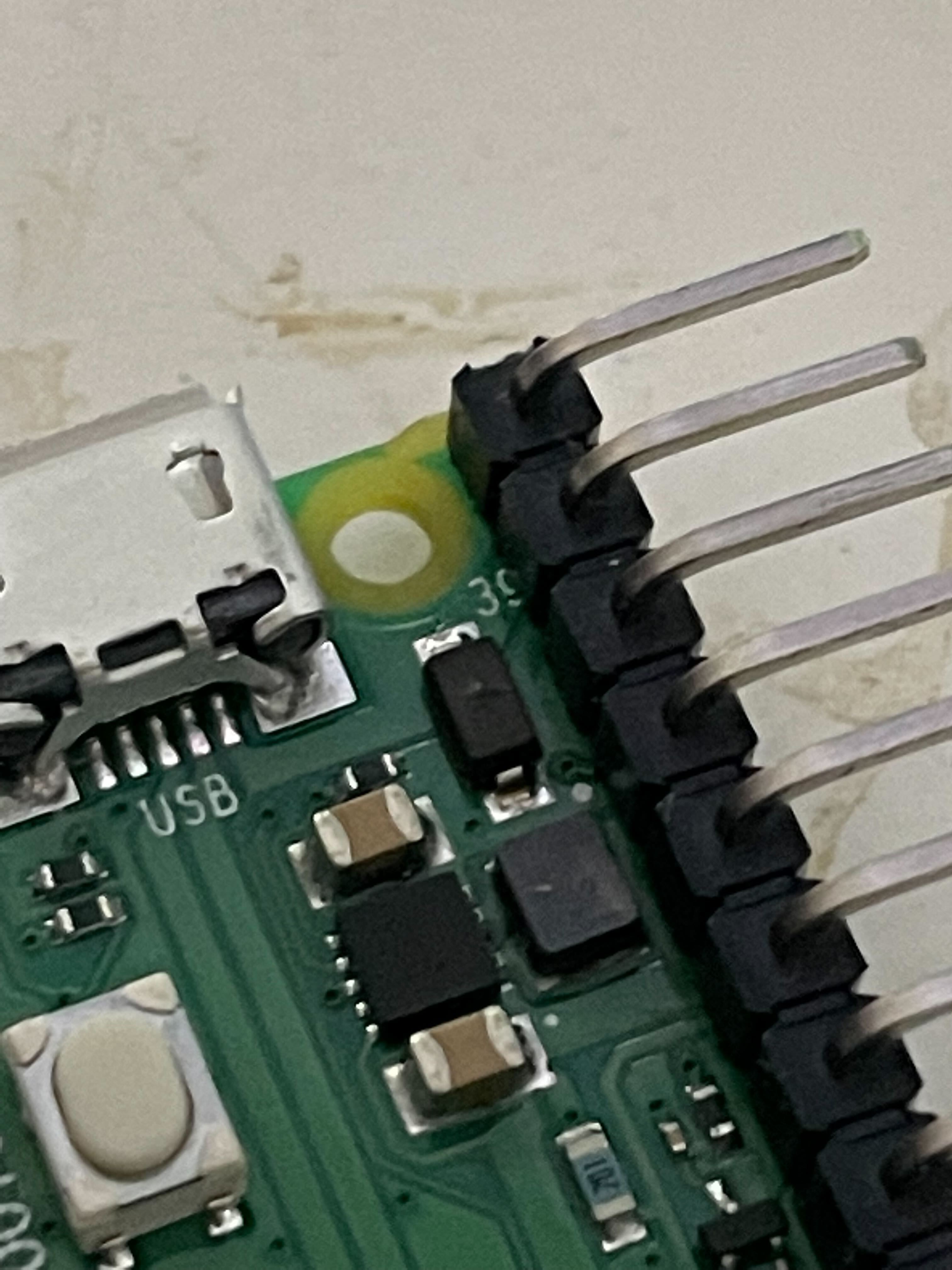
 obsidian fjord
Hey everyone, I'm running an rpi 4 with the 64bit OS installed. Under the Add / Remove software program, on the Documentation tab, there's a file called The Advanced Bash-scripting Guide (abs-guide-10-4) I successfully installed it, I see the black checkmark to the left, but I can't for the life of me find out where this was downloaded to. I check some of the more obvious locations, I tried whereis in the terminal, but that's basically the extent of my ability to figure this out.
Any help or an idea of what to Google would be appreciated
umbral sable
obsidian fjord
Hey everyone, I'm running an rpi 4 with the 64bit OS installed. Under the Add / ...
Possibly in /usr/share/doc?
night sail
fickle rose
raspi-config says no wireless interfaces found
what do lspci and iwconfig give you?
fickle rose
I’l check tomorrow
queen moth
Anyone else complete the set up for the hyperpixel 4 and it's not rotated?
Also I am trying to make a basic bash script to set up a Linux distro by checking for a command and then sudo apt-get install command if it is not found, if anyone has any tips
fickle rose
night sail
what do lspci and iwconfig give you?
Iwconfig said no wireless extensions and lspci cannot find any working access method
night sail
fickle rose
Iwconfig said no wireless extensions and lspci cannot find any working access me...
if lspci won't run I'd start there. Sounds like something bigger might be going on
fickle rose

I’ve searched google but can’t get any related results
I don’t think I’m searching the right thing
night sail
fickle rose
I'm assuming whatever is preventing "lspci" from reading from /proc is also likely preventing the network stack from seeing your wireless card.
For kicks and giggles, can you try "sudo lspci" ?
fickle rose
Tried it
night sail
here's an example output from my XPS:
 fickle rose
I ran ls on /proc/bus and the only thing in there is “input”
still stone
What does dmesg say about teh devices seen while booting?