#help-with-linux-sbcs
1 messages · Page 27 of 1
 olive pawn
 steady rose
it was written in arduino
steady rose
#import <Adafruit_NeoPixel.h>

Adafruit_NeoPixel strip(10, 8);

uint8_t pixel = 0;

void setup() {
  Serial.begin(9600);

  strip.begin();
}

void loop() {
  Serial.println("Hello world!");
  strip.clear();
  strip.setPixelColor(pixel++ % 10, 0xADAF00);
  strip.show();
  delay(500);
}
luckily still had it 🙂
olive pawn
thank you so much
that helps because i think the problem was from the code that i was sending for the signal
olive pawn
hey cater
so good news, thanks to you, i got the serial data to work with the ultrasonic sensor
and its displaying numbers

but for some reason, it shows 1 word per line
and also has this weird \r and \n after
 rotund pivot
the sender must be sending slowly? read tries to get whatever it can within the timeout (default = 1 second)
the \r and \n are line ending control characters
try readline()
olive pawn
ahhhh thanks!
olive pawn
rotund pivot
the `\r` and `\n` are line ending control characters
and do you know how to get rid of the ending control characters?
im sorry these might be dumb questions im just really getting started with python
rotund pivot
they should be there if you want to use readline()
olive pawn
 rotund pivot
most any multi-line text source will have line ending control characters embedded
you could ignore them or filter them out
 civic rune
Have you tried the forums? They are the official way to get help
rotund pivot
if so, you could try .strip() https://docs.python.org/3/library/stdtypes.html#str.strip
olive pawn
alright thank you
 slender meadow
Hi All,
Am I missing some basic fundamental here?
I have a flow meter with a hall effect sensor giving me 107 pulses per liter and a max flow rate or 150 liters per min.
I run my signal generator at 269Hz (basically 150 LPM) and I can figure out the math to interpret how to display the total liters anywhere near the built in lcd display on the flowmeter (that has the 107 K-Factor set in it).
What am I missing?
 olive haven
slender meadow
Hi All,
Am I missing some basic fundamental here?
I have a flow meter with a hal...
olive haven
slender meadow
Hi All,
Am I missing some basic fundamental here?
I have a flow meter with a hal...
How are you counting the pulses? What do you mean by signal generator? How do you have the sensor connected to the Pi? What does your code look like?
slender meadow
I am counting the pulses using interrupts.
Cheap aliexpress signal generator with 3v3 input with a VPP +2.9 on the input pin on pi.
Checked signal with DSO and its running at 269Hz neat square wave. I am measuring on the FALLING.
Sensors all connected via breadboard:
LCD of flow meter
DSO
Signal Generator Output line
Pin 16 with built in Pull Resistor on.
Code in python:
import time
import RPi.GPIO as GPIO

#Global variables
pin_counter = 0
pin_number = 16
timeout = time.time() + 60

def pin_handler(pin):
  global pin_counter

  pin_counter += 1
  print("pin", pin_number, " - state: ", GPIO.input(pin_number), " counter: ", pin_counter, " Liters: ", pin_counter * (1 / 107311))

#GPIO Configuration
GPIO.setmode(GPIO.BCM)
GPIO.setup(pin_number, GPIO.IN, pull_up_down=GPIO.PUD_UP)

GPIO.add_event_detect(pin_number, GPIO.FALLING, pin_handler)

try:
  while True:
    # time.sleep(60)
    if time.time() > timeout:
        break
except KeyboardInterrupt:
  GPIO.cleanup()
Hope that helps...
I'm assuming my issue is here:
Liters: ", pin_counter * (1 / 107311))
You had said 107 pulses/liter; is it really 107K?
slender meadow
its 107.311 to on the calibration certificate
olive haven
i.e. I would have thought pin_counter / 107 would give you the right answer. So you're missing a decimal point after the 7
slender meadow
and what is programmed into the LCD counter
slender meadow
olive haven
i.e. I would have thought pin_counter / 107 would give you the right answer. So...
I'v tried that, still different. But going to doing it again now to be 100% sure
ended:
py script:
Counter = 1105, Liters = 10.4
LCD Screen:
112.60
LCD is in Liters
ran this:
import time
import RPi.GPIO as GPIO

#Global variables
pin_counter = 0
pin_number = 16
timeout = time.time() + 60

def pin_handler(pin):
  global pin_counter

  pin_counter += 1
  print("pin", pin_number, " - state: ", GPIO.input(pin_number), " counter: ", pin_counter, " Liters: ", pin_counter / 107.311)

#GPIO Configuration
GPIO.setmode(GPIO.BCM)
GPIO.setup(pin_number, GPIO.IN, pull_up_down=GPIO.PUD_UP)

GPIO.add_event_detect(pin_number, GPIO.FALLING, pin_handler)

try:
  while True:
    # time.sleep(60)
    if time.time() > timeout:
        break
except KeyboardInterrupt:
  GPIO.cleanup()
 umbral sable
1105 counts is about 4 seconds, at 150LPM, that would indeed be about 10 liters, so that looks right given the numbers you've given.
umbral sable
Were they both started at the same time, or could the LCD have been counting pulses earlier?
slender meadow
both a possibility. my "lab" is far from getting perfect matches
olive haven
It seems to me possible that having a print statement in pin_handler is causing it to miss interrupts. Maybe you should try just incrementing the count in that routine, and periodically print out the current count in the while-loop.
 misty rock
hi. i'm trying to use a USB to TTL HW 597 in order to control a conveyor. i was able to get it talking no problem under windows, but the ch34x module for linux doesn't appear to be working as i can't connect using the same params as on the windows box
umbral sable
Are you getting any errors? Are you using just a terminal app like minicom, or some more specialized software?
 umbral sable
So what do you mean by "can't connect"? Is the terminal app giving you an error in opening /dev/ttyUSB0, or are you getting no data from the conveyor like you would normally expect?
misty rock
i am getting a blank screen as if i put in the wrong settings
but i verified that it's 115200 bps / 8N1, no handshake
i just don't understand how to debug now
umbral sable
Does the conveyor ordinarily print out data on its own, or does it only respond to commands you type?
misty rock
yeah it responds with Ok
i think the driver must be borked, sparkfun has a tutorial that talks about patched drivers
steady rose
can try shorting the TX/RX cables for a simple loop back test?
umbral sable
One thing you could do to narrow things down is just make a loopback connection between TX and RX, removing the conveyor from the circuit, and see whether the serial cable works to echo its own data.
Hahaha, <high fives @steady rose>
misty rock
ok, i didn't do that since i verified the usb to ttl works on windows
i'll give it a go
misty rock
echo kinda seemed to work
i mean it did, but it seemed slow in the process of echoing
i don't have enough experience with serial to know what it should be like
misty rock
i switched to another cable and echo test went fine, but trying to use that cable didn't yield any results
slender meadow
olive haven
It seems to me possible that having a print statement in `pin_handler` is causin...
Thanks @olive haven, That kinda makes sense. Could you suggest an easy way for me to do this? Maybe print the total every 1 sec?
 hardy plaza
 foggy onyx
for performance ??
foggy onyx
for performance ??
You mean to see how slow a Pi can go?
foggy onyx
hardy plaza
You mean to see how slow a Pi can go?
no, how fast it can go
hardy plaza
Well, I think you'd be finding out how slow it can go really.
foggy onyx
i wanted to make it fast
olive haven
slender meadow
Thanks <@!465677950411603969>, That kinda makes sense. Could you suggest an easy...
Basically use the same technique you did with timeout: change the while-loop to something like:
print_interval = 1
print_time = time.time() + print_interval
while True:
    t = time.time()
    if t >= print_time:
        print(...) # include print_time in string
        print_time = t + print_interval
    if t > timeout:
        break
and custmizable
hardy plaza
The more complicated a window manager the slower the experience. KDE Plasma makes very significantly more demands on a computer than the default Raspberry Pi OS's window manager.
It will likely run, but it'll likely be very slow.
hardy plaza
Bad for speed, yes. Not bad as an experiment to see how fast/slow it is. But the fastest Pi is a Pi 4 and it won't be anywhere near as fast as a cheap laptop.
No, the 64 bit OS has been released (finally).
foggy onyx
when ??
hardy plaza

After a year of beta, it's time to open up 64-bit Raspberry Pi OS to a wider audience.
foggy onyx
hardy plaza
https://www.raspberrypi.com/news/raspberry-pi-os-64-bit/
can i update it now ??
should i ??
from 32 to 64 ??
hardy plaza
You won't really notice much of a difference unless you're using software that can take advantage of it. If you read the article there are some reasons to update but for most people it won't matter. I've been using the beta for about a year and updated to the new release and it works fine. There are some issues with the camera that aren't related to 32/64 bit but to changes to the new OS version that you should be aware of if you're using the standard Pi camera. Apart from that have a go. It's the future...
For the vast majority of things it isn't going to give you better performance. Again, unless you're running specific software that can use the A64 instruction set, which are mostly closed-source commercial applications. But on the other hand it doesn't hurt to run 64 bits either. I wanted the latest OS because I wanted the latest version of Python built-in, so I upgraded.
hardy plaza
You're welcome. The fastest desktop performance on a Pi will be the default I believe. KDE Plasma would be an interesting experiment but it'll certainly run slower.
...off to bed for me, ciao
foggy onyx
hardy plaza
You're welcome. The fastest desktop performance on a Pi will be the default I be...
can i install theams in defalt ??
hardy plaza
Yes, search on the web for "Raspberry Pi desktop themes"
The Raspberry Pi OS is using a modified version of the LXDE desktop environment, so I believe any of the LXDE themes would probably work.
foggy onyx
hardy plaza
The Raspberry Pi OS is using a modified version of the LXDE desktop environment,...
and will it matter performance ?
hardy plaza
No, it won't
foggy onyx
ok
hardy plaza
Have fun!
foggy onyx
now sleep 👐
foggy onyx
hi folks,
i am Padmanabh. i have install terminator on rpi successfully and now can use it but i am trying to set it as default but it is not working.
i have tried sudo update-alternatives --configx-terminal-emulator but didn't worked
olive haven
foggy onyx
hi folks,
i am Padmanabh. i have install terminator on rpi successfully and now ...
You need a space between --config and x-terminal-emulator, and generally after any -- option that takes an argument.
foggy onyx
olive haven
You need a space between `--config` and `x-terminal-emulator`, and generally aft...
Ye
Sorry, it was mistake of typing
But i ran orignal command
It didn't worked
olive haven
You could try --list with the same argument to see if it actually has any alternatives.
Looks like the option you want to use is
--set <name> <path> set <path> as alternative for <name> to register terminator as an alternative
foggy onyx
olive haven
Looks like the option you want to use is
`--set <name> <path> set <path> as...
While running command, i select Terminator (auto) but it doesn't affect anything on system
I tried it many times
But it allways tell Terminator is selected but it doesn't affect anything
olive haven
I'm not familiar with Terminator or with the update-alternatives command, so I don't know what the problem is. Did you read the man page for the command to see if you have to reboot or whatever? Is Terminator really an X terminal emulator? Good luck!
foggy onyx
Yea, terminator has many features more than default one
@olive haven i got a solution but
I don't know where change Settings Manager is located
olive haven
Something in the Preferences menu? Raspberry Pi Configuration? Dunno what setting(s) you're trying to change.
The mention in the link you posted is for Ubuntu; I presume you're running Raspberry Pi OS.
foggy onyx
olive haven
The mention in the link you posted is for Ubuntu; I presume you're running Raspb...
Yea, I am on default one
What should id do ??
 lost wolf
Hello. Please avoid cross-posting messages in more than one channel. Folks who can help will find it in any channel. I think you'll get faster assistance in #help-with-projects, but for future reference, please post in one place, and be patient. Most folks here are volunteers giving their time when they can. 🙂
 frozen shoal
lost wolf
Hello. Please avoid cross-posting messages in more than one channel. Folks who c...
frozen shoal
lost wolf
Hello. Please avoid cross-posting messages in more than one channel. Folks who c...
Oh, I was about to delete that, I just read that this was for raspberry pi linux help
lost wolf
Ah, no worries. Thanks!
frozen shoal
Wasn't sure if it was only for linux or if it was for everything that was associated with raspberry pis
lost wolf
Everything associated with Raspberry Pi. The addition of the word "Linux" was to try to stop folks from posting here about the RPi Pico.
 fervent shoal
Hello, I bought an MPU9250 and thinking of using this microsoft library on my raspberry pi with c#
https://github.com/dotnet/iot/blob/main/src/devices/Mpu9250/README.md

GitHub
This repo includes .NET Core implementations for various IoT boards, chips, displays and PCBs. - iot/README.md at main · dotnet/iot
simple question: what does a magnetometer even do lol
is it similar to a compass ?
 turbid rivet
fervent shoal
is it similar to a compass ?
turbid rivet
fervent shoal
is it similar to a compass ?
It's basically a digital compass, yes. It measures the magnitude of a magnetic field in its axes to determine north (or the direction and strength of the closest magnet...)
fervent shoal
I guess being less then 10cm away from a servo motor would affect the accuracy
turbid rivet
Yeah, best to keep those away from anything that works by creating magnetic fields haha
 stray jackal
I need to choose which version of the pi to use for a project, wondering if anyone can help. Here are my requirements:
- Can support WiFi, 2 or ideally 3 full size USBs, HDMI, audio out.
- I need a lot, like close to 300 🫣
These will be loaded with learning software for kids in schools, where they would be distributed.
What version of the pi would be appropriate, and am I even being realistic that I'd be able to get that many?
lost wolf
I'm not certain on the feature set question, but I can guarantee it's not realistic to find that number at a normal price right now. They're impossible to find at the moment. And most places will only sell you one at a time.
The only people who are selling them in multiples are charging significantly over the RPi price.
stray jackal
And this is true for older versions? If I dropped the Wi-Fi requirement, could I be looking at very old versions?
 opaque wagon
Yes (all Pis are selling expensive)
lost wolf
Some of the older ones aren't even being made anymore.
Replaced by the newer ones, in some cases.
opaque wagon
But I would recommend the Pi 400:
https://www.adafruit.com/product/4795
And in kit form: (only need display I'm pretty sure)
https://www.adafruit.com/product/4796

Raspberry Pi 400 is a complete Raspberry Pi 4-based personal computer, integrated into a keyboard. The Pi 4 is the first computer from the Pi Foundation that really feels 'desktop ...

Raspberry Pi 400 is a complete Raspberry Pi 4-based personal computer, integrated into a keyboard. The Pi 4 is the first computer from the Pi Foundation that really feels 'desktop ...
But it would be very hard to obtain 300 of them in a reasonble time period
Plus you have scalpers :/
And plus, Pi 4 is much better to work with in terms of speed then the Pi 3 or older
(which is what the Pi 400 has)
stray jackal
Dang, this was not what I expected :(
Are there alternatives I could look into for very affordable Linux computers?
stray jackal
opaque wagon
And plus, Pi 4 is much better to work with in terms of speed then the Pi 3 or ol...
There's a particular program that this is to be used with, I suspect even very old versions would handle it fine (as long as I can get python 3.7 running)
opaque wagon
Maybe something like the Pi Zero if you don't care about performance (cheap, but expensive now cause, well you know)
Unfortunately all Pi Zeros has one mini HDMI and one micro-OTG USB so you need at the very least an adapter, or a USB hub
https://www.adafruit.com/product/2885
Pi Zero W (with WiFi)
https://www.adafruit.com/product/3400
Pi Zero W in kit version:
https://www.adafruit.com/product/3410
Pi Zero 2W (which is literally the same as the Pi Zero except different processor so faster)
https://www.adafruit.com/product/5291

At first glance, the Pi Zero isn't much. It just looks like a slimmed down version of the Raspberry Pi we know and love. But when we started to think of the possibilities - ...
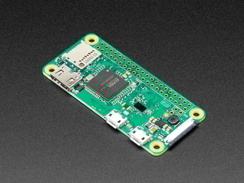
If you didn't think that the Raspberry Pi Zero could possibly get any better, then boy do we have a pleasant surprise for you! The new Raspberry Pi Zero W offers all the benefits of ...

Remember those cereal commercials that would always say, "part of a complete breakfast"? Well the Pi Zero's a lot like that bowl of cereal - while it's great on ...

Raspberry Pi Zero 2 W is the latest product in Raspberry Pi's most affordable range of single-board computers. The successor to the breakthrough Raspberry Pi Zero W, Raspberry Pi Zero 2 ...
(note that I've heard using the desktop on the original Pi Zero is extremely slow)
opaque wagon
stray jackal
Dang, this was not what I expected :(
Are there alternatives I could look into f...
There are plenty of alternatives (Orange Pi, etc.) but they have poor software support compared to the Raspberry Pis
stray jackal
I guess I have an open question about how much performance I really need, which I can solve with testing. (Python 3.7, kivi framework, and midi processing.)
But am I going to have the same issue with something like a pi zero, that buying even 100 is just not practical? If I have to put 3D printed cases with integrated adapters on the table, that wouldn't be the end of the world.
hardy plaza
lost wolf
Some of the older ones aren't even being made anymore.
Yes, but I do believe the non-WiFi Pi Zero is actually available in some places, but as you say, even the Pi Zero is usually limited to single item purchases.
Doing any kind of project right now that involves multiple Raspberry Pis that one doesn't already have at hand is pretty much impossible. How this will affect the entire community of Raspberry Pi users is a rather dark thought. It's hard to build things with Raspberry Pis when nobody can get any.
If all you need is a small Single Board Computer that can run Linux there are dozens of options, all of the alternative fruit and vegetable "Pi" models. Almost none of them will be entirely hardware and software compatible with the Raspberry Pi (despite often claiming that), and none will have the community around them that one enjoys with the Raspberry Pi. But if you simply need 300 small Linux computers, something like a Pine board or Nano Pi running Armbian would certainly work. A bit of hic sunt dracones... but possible, and at volume purchases as well (I believe).
https://www.friendlyelec.com/index.php?route=product/product&path=69&product_id=212
https://pine64.com/product/pine-a64-512mb-board/
Pine does have a reasonable community around their boards, Nano Pi not much at all for hardware but if you're using Armbian (and you likely will be) the Armbian community is real and functional and generally helpful (just never mention the words "Raspberry Pi" in their midst or they will bite your head off).
Oranges are okay, avoid the Banana.
stray jackal
Thank you for this! In my case, compatibility with anything really doesn't matter at all!
hardy plaza
stray jackal
Thank you for this! In my case, compatibility with anything really doesn't matte...
I've used Nano Pis and you could probably buy 10,000 of them, but I'd probably contact FriendlyElec in Guangzhou directly and see how many they can supply. I'm sure they'd be happy to supply lots of product to anyone. You can buy various fruits and vegetables off of AliExpress from multiple secondary vendors, but as you may know that's a bit of a minefield. FriendlyElec don't have their own store front on AliExpress but Orange Pi (Shenzhen Xunlong Software Company) do.
I've ran my Nano Pis with Armbian, but whatever model you choose you should be sure beforehand that the Armbian distro is available (and works okay) for that model. Maybe buy one as a prototype and check it out before buying 299 more...
The Nano Pi NEO Core-LTS (Long Term Support) is probably your best bet on the lower side of their lineup. Being "LTS" I guess means they will continue making and supporting the board, whereas others (like the Fire3 octo-core) are more prone to disappearing due to the rarity of some of the components.
There is even a "shield" available for it that makes it into the form factor of a Raspberry Pi 3, though of course hardware and software will not be compatible, just physical form factor (e.g., for fitting it into an RPi 3 case). The shield also provides an M.2 socket for adding an SSD, as well as Ethernet and other connections.
 ruby night
stray jackal
I need to choose which version of the pi to use for a project, wondering if anyo...
ruby night
stray jackal
I need to choose which version of the pi to use for a project, wondering if anyo...
See the invitation at the end of this note from the Raspberry Pi Foundation about “large orders“ https://www.raspberrypi.com/news/production-and-supply-chain-update/

As you will have noticed, it can be hard to buy a Raspberry Pi unit at the moment. We thought it would be helpful to provide an update.
 tepid flare
stray jackal
Thank you for this! In my case, compatibility with anything really doesn't matte...
tepid flare
stray jackal
Thank you for this! In my case, compatibility with anything really doesn't matte...
Apparently if you have a legitimate business use, you can buy raspberry pis directly, you have to email them about it. That's what they are prioritizing
stray jackal
I shot them an email, I wonder what they consider a bulk purchase :)
civic rune
tepid flare
Apparently if you have a legitimate business use, you can buy raspberry pis dire...
hmmmm
Thank you!
tepid flare
ruby night
See the invitation at the end of this note from the Raspberry Pi Foundation abou...
I expect they will ask some questions to be sure you aren't a reseller
ruby night
tepid flare
I expect they will ask some questions to be sure you aren't a reseller
I would hope so!
 fallow topaz
Hello anyone there? Is there an alternative to postman that will work on Raspbian 64 bit for raspberry pi 4?
 carmine hollow
anyone here used a Pimoroni LiPo Shim? I seem to be killing SD cards with it.
 faint sparrow
Hello, I have raspberry pi pico can anyone tell me how to connect pico to speaker??
 pallid relic
Hey everyone, Since 4 days i’m having an issue while connecting an adafruit feather sense to raspberry pi 4 through BLE using Blinka Library and the raspberry pi to adafruit io through wifi , i followed all the description of the tutorial online uploaded by adafruit but at the end the pi scan and don’t receive the data from the feather sense , tried more than 5 times but no solution, can someone help please 🙏
This what is popping

This is what it should pop


 twin briar
Hi.
I cant seem to finish running sudo apt-get update 😦
GET: https://raspbian.raspberrypi.org/raspbian bullseye/main armhf Packages
my internet is 64Mbps
the update is stuck in here then presents an error with an ip address. i forgot to record the error and Iam trying to replicate it now.
the pi I am using is raspi 3b+ with a newly installed 32bit bullseye via rpi imager
error:
failed to fetch https://raspbian.raspberrypi.org/raspbian/dists/bullseye/main/binary-armhf/Packages
Undetermined Error [IP: 93.93.12**** 80]
some index files failed to download. they have been ignored or old ones used instead.
 plain wedge
My post is probably better suited here... I've gone down a rabbit hole this morning and I was wondering if anyone has tried the cyberdeck bonnet on anything other than a pi 400. I can't see any reason why it wouldn't work on a say a pi zero 2. Thinking about building an extremely small footprint portable terminal and I think it would look a bit nicer/sit on a table better than pitft sandwhich.
steady rose
it should work on any pi. they all (expect for now very old models) have a common pinout on the 40 pin header.
 last bramble
how do i rotate my 3.5 inch lcd's display?
tried adding display_lcd=2 on the config.txt file but didnt do anything
im on a raspberry pi 4
and cant seem to find many solutions online
turbid rivet
last bramble
tried adding display_lcd=2 on the config.txt file but didnt do anything
Did you mean lcd_rotate=2?
turbid rivet
What kind of display, exactly?
last bramble
turbid rivet
What kind of display, exactly?
A 3.5 inch LCD display
Connects via GPIO pins
It's not the official one but it gets the job done
I only want it to rotate
turbid rivet
last bramble
Connects via GPIO pins
Is it DPI, SPI, etc? lcd_rotate should work for DPI, but not sure about SPI...
last bramble
turbid rivet
Is it DPI, SPI, etc? `lcd_rotate` should work for DPI, but not sure about SPI...
Soer of late response but pretty sure it's DPI
 lament swan
Hello, I want to get deterministic sampling rate on a raspberry pi for the LSM6DSOX breakout board. I am using the adafruit blinka and adafruit lsm6dsox libraries. On a microcontroller, I use timer interrupts to fill a circular(FIFO) buffer at each interrupt, while running serial print in the main loop that dumps the buffer over serial in between the interrupts. Granted, this is not real-time, since the data that's being dumped from the buffer is old data but I am only collecting the data at a fixed interval. How would I go about doing something similar on the RPi using python. Should I turn to threading? One thread uses time.time() in a loop to get the acceleration at a fixed interval, and the other (possibly main) thread prints. How do I prioritize the sampling thread over the printing thread?
umbral sable
lament swan
Hello, I want to get deterministic sampling rate on a raspberry pi for the LSM6D...
One thing you should consider is using the sensor's built-in FIFO. That way it would collect samples at an exact interval, and then the Pi could retrieve them in the original order on its own, possibly less reliable, schedule.
lament swan
Ah, that's an idea! And if I set the sensor rate, then I can assume that they are sampled at the rate the sensor says it's sampling at ?
I'm assuming the sensor doesn't have a time stamp which would be awesome, but I don't think that's how these sensors work
umbral sable
They don't have a time stamp, per se, but they do often have some sort of sync pin which gets recorded in the FIFO with the data, so if you wanted to know what the sample was at a particular time, you'd strobe that pin to mark the next piece of data.
And you can query for the FIFO depth, so you can calculate when, relative to now, the data was likely taken.
lament swan
Thank you so much! I'll dig into that and get back to you!
 pine bough
I have a question about the rp 2040. Does anyone know the current output for the digital pins?
 wraith grove
Maximum Total
IOVDD current
Sum of all current
being sourced by
GPIO and QSPI
pins
50 mA
page 639 of the datasheet
faint sparrow
Hello, i recently installed the video looper software on my raspberry pi. I was wondering if anyone managed to direct the software to scan for wideos on an URL of my choise? The only 2 options i magaged to modify are usb or directory folder.
ruby night
I have no objection to this change (removing the default user "pi") but I expect it will break a lot of scripts! https://www.raspberrypi.com/news/raspberry-pi-bullseye-update-april-2022/?fbclid=IwAR1XZtd0Ke1-4ooNUP6cFiDnJqBdXxL7tFA3ufV0Eh8eW3XB2RkB2mdHdVs
civic rune
sigh, one more thing to document!
 cinder wadi
Hello all, I’m having an issue with the Adafruit 2.2 Pitft & RPi Zero w1.1 RPi OSI’ve followed the learn.adafruit Easy Install Issue - screen will not show display desktop sudo python3 adafruit-pitft.py —display=22 —rotation=90 —install-type=fbcp * screen will display if I run the “Console Install Command” Any help would be very much appreciated
Pictured is the "Console" but i would like it to be mirrored to the HDMI

 light horizon
hey y'all, quick question: im trying to find my ESP32, which is currently plugged into an RPi USB port. i am trying to program the ESP32 from the Pi (like a little field dev station I can use on the sidewalk in LA where I teach). I saw something somewhere that said I should be able to pull up the port for the ESP32 with dmesg | grep ttyUSB, which does not return anything. Am I doing something incorrectly or is it possible that serial port naming has changed recently?
I should mention that this ESP32 can be discovered on any other computer so I am sure this is an/my specific confusion regarding a RPi issue 🙂
 steep jackal
Hi, I'm having some trouble with Raspbian trying to recognize a DS1337+ i2c RTC.
The issue is that Linux uses a single driver for several similar chips.
The ds1307 driver handles the 1337. I thought I've given it the right name. I'm setting it up with:
modprobe rtc-ds1307
echo ds1337 0x68 > /sys/class/i2c-adapter/i2c-1/new_device
The good news: I've got a working /dev/rtc0 and I can write system time to it and read time from it. hwclock works.
The bad news: It seems to recognize this only as a 1307. Or, at least, when I use ioctl to set an alarm time (a function the 1337 has, but the 1307 doesn't), nothing gets written to the i2c bus. My project needs the alarm feature of the DS1337+, and looking at the Linux source code, there are alarm write and read methods, but they're not being called.
I am assuming I'm doing something wrong in not adequately telling Linux which ds1307-compatible chip it is.
I'm running Raspbian with a 5.10.17+ kernel.
 red knoll
@light horizon Due to an unfortunate oversight, I can't actually access any of my Pis right now to check for you amd not having the Raspian bits all swapped in in my brain, I don't have a detailed answer. But, since nobody else responded, I'll give you where I would go next on this. The data from dmesg will have the info you need, but grepping for it requires preknowledge of what you're looking for. Doing a dmesg | less will let you look at it all and you can probably quickly page through to find the right thing. And if you don't see it the first time, it's easy enough to type uparrow enter to try again.
light horizon
red knoll
<@689535024462168077> Due to an unfortunate oversight, I can't actually access a...
Fantastic, appreciate this response a ton and will give this a try. Thx! 🙏🏻
 remote cove
Would you guys recommend that I use rasbian 64 bit instead of 32 bit on my RaspberryPi 3
(Pls ping me)
turbid rivet
remote cove
Would you guys recommend that I use rasbian 64 bit instead of 32 bit on my Raspb...
No, Pi 3 only has 1GB of RAM, so there's no benefit to using a 64-bit OS. 64-bit operating systems are used with systems that have 4GB RAM or more, IIRC.
olive pawn
remote cove
Would you guys recommend that I use rasbian 64 bit instead of 32 bit on my Raspb...
raspi 4>>>
remote cove
olive pawn
raspi 4>>>
What?
olive pawn
remote cove
What?
use raspberry pi 4 for 64-bit
remote cove
olive pawn
use raspberry pi 4 for 64-bit
I have a raspPi 3. I will not buy new hardware. I think I will stick to 32 bit version
olive pawn
remote cove
I have a raspPi 3. I will not buy new hardware. I think I will stick to 32 bit v...
i was just saying that it is best to use 64 bit. If you dont have it, ur limited in 64
remote cove
olive pawn
i was just saying that it is best to use 64 bit. If you dont have it, ur limited...
I'm pretty shure I'm not limited to 32 bits. The hardware supports 64 bits. It's just that I don't get a huge benefit from 64 bits, because I only have 1 GB RAM.
olive pawn
remote cove
I'm pretty shure I'm not *limited* to 32 bits. The hardware supports 64 bits. It...
well what is the reason to ask if you are pretty shure ||#nicespelling||
remote cove
I was shure that it supported 64 bits. I was not shure what the advantages/disadvantages are. I just learned some of those from Hem.
olive pawn
yeah you are correct:

yeah but i think the best thing about 64 is that it still runs rasbian with unmodified drives
which is a big plus when switching hardrives from your raspberry pi server, for example. There migth be many formats that the 32 bit doesn't recognize like the exFAT, which can be a big annoying
but your ram would bottleneck the fairly fast 4 core 64-bit ARMv8 SoC
if do not need to utilize gpu memory, then reduce that from the 1 gig ram you get on a raspi 3 b+
but if you are that keen to get more ram, you can use ZRAM
it could help, but ofc it cant physically increase the ram
Since the VC4 GPU in the SoC not being able to address more than 1GB
If you want to look into the more compressed memory side, here is a guide to zram: https://doc.ubuntu-fr.org/zram
@remote cove
olive haven
From the news release announcing 64-bit Raspberry PI OS (https://www.raspberrypi.com/news/raspberry-pi-os-64-bit/):
"But we’ve come to realise that there are reasons to choose a 64-bit operating system over a 32-bit one. Compatibility is a key concern: many closed-source applications are only available for arm64, and open-source ones aren’t fully optimised for the armhf port. Beyond that there are some performance benefits intrinsic to the A64 instruction set: today, these are most visible in benchmarks, but the assumption is that these will feed through into real-world application performance in the future."
Example: I'm interested in the Faust DSP language, but it only supports 64-bit targets, at least for Linux. If I got sufficiently interested on running Faust code on a Pi, I would switch to 64 bit.
last bramble
why does my raspberry pi boot up to a black screen?
it was working fine yesterday but when i boot it up the mini lcd attached to it shows a black screen
hardy plaza
last bramble
it was working fine yesterday but when i boot it up the mini lcd attached to it ...
It could be a hardware or a software problem. If you have a Linux computer available (even anothe Pi), take the SD card out of your Pi and mount it on a Linux computer. Or if you know how to remote ssh into the Pi, that'd work to. What you want to do is look at the log files, found in /var/log/. You may find some clues there. Absent what's in the logs anyone out here on the Internet is just guessing.
last bramble
hardy plaza
It could be a hardware or a software problem. If you have a Linux computer avail...
i own a linux computer yes,
and i cant seem to ssh into it either
hardy plaza
So it may not be running then. So mount the SD card on your Linux computer and look into the /var/log/ directory on the /rootfs partition.
last bramble
ill check that out later, thanks
hardy plaza
If you sort the log files by date you'll see the most recent ones, which are most likely to have your clue. "syslog" is probably it.
last bramble
hardy plaza
If you sort the log files by date you'll see the most recent ones, which are mos...
i found syslog but cant seem to open it
is it a text file or do i need something in order to see it
umbral sable
Should just be text.
umbral sable
/var/log/syslog What error are you getting when you try to view it?
faint sparrow
you need root
regular debian a member of group 'adm' is enough for /var/log/syslog.
hardy plaza
Yeah, but if you're mounting the SD card on a different computer that shouldn't be the case, or certainly isn't a barrier when I do it (yes, it's ownership is root:root but I can edit it without sudo).
In any case, your solution is:
sudo vi $PATH_TO_ROOT_ON_SD_CARD/var/logs/syslog
sorry for late response, but this is what i found at the end of the file.
Apr  8 13:38:24 raspberrypi systemd[1]: apt-daily-upgrade.service: Succeeded.
Apr  8 13:38:24 raspberrypi systemd[1]: Finished Daily apt upgrade and clean activities.
Apr  8 13:38:24 raspberrypi systemd[1]: apt-daily-upgrade.service: Consumed 1.291s CPU t
ime.
Apr  8 13:45:52 raspberrypi systemd[1]: Starting Cleanup of Temporary Directories...
Apr  8 13:45:52 raspberrypi systemd[1]: systemd-tmpfiles-clean.service: Succeeded.
Apr  8 13:45:52 raspberrypi systemd[1]: Finished Cleanup of Temporary Directories.
Apr  8 14:17:01 raspberrypi CRON[1285]: (root) CMD (   cd / && run-parts --report /etc/c
ron.hourly)
Apr  8 14:31:02 raspberrypi rngd[456]: stats: bits received from HRNG source: 80064
Apr  8 14:31:02 raspberrypi rngd[456]: stats: bits sent to kernel pool: 33312
Apr  8 14:31:02 raspberrypi rngd[456]: stats: entropy added to kernel pool: 33312
Apr  8 14:31:02 raspberrypi rngd[456]: stats: FIPS 140-2 successes: 4
Apr  8 14:31:02 raspberrypi rngd[456]: stats: FIPS 140-2 failures: 0
Apr  8 14:31:02 raspberrypi rngd[456]: stats: FIPS 140-2(2001-10-10) Monobit: 0
Apr  8 14:31:02 raspberrypi rngd[456]: stats: FIPS 140-2(2001-10-10) Poker: 0
Apr  8 14:31:02 raspberrypi rngd[456]: stats: FIPS 140-2(2001-10-10) Runs: 0
Apr  8 14:31:02 raspberrypi rngd[456]: stats: FIPS 140-2(2001-10-10) Long run: 0
Apr  8 14:31:02 raspberrypi rngd[456]: stats: FIPS 140-2(2001-10-10) Continuous run: 0
Apr  8 14:31:02 raspberrypi rngd[456]: stats: HRNG source speed: (min=400.995; avg=459.2
59; max=541.137)Kibits/s
Apr  8 14:31:02 raspberrypi rngd[456]: stats: FIPS tests speed: (min=20.378; avg=24.675;
 max=29.709)Mibits/s
Apr  8 14:31:02 raspberrypi rngd[456]: stats: Lowest ready-buffers level: 2
Apr  8 14:31:02 raspberrypi rngd[456]: stats: Entropy starvations: 0
Apr  8 14:31:02 raspberrypi rngd[456]: stats: Time spent starving for entropy: (min=0; a
vg=0.000; max=0)us
keep in mind the screen goes entirely black after a few seconds on the display
and the green light doesnt blink at all
i cant seem to ssh into the pi at all
faint sparrow
If you start with a regular SD card booting a regular OS you can experiment.
If that won't work it could be the hardware.
You would likely need a recommended display; HDMI displays work for me.
I've also used the Adafruit VGA adaptor (HDMI to VGA) to work with old displays.
Similarly, you can enable a getty on the hardware serial port of the raspberry pi.
and login there.
last bramble
honestly ill probably just try reinstalling rpiOS
since i never had much data on it
to begin with
faint sparrow
if you had a spare SD card that'd be non-destructive.
last bramble
i have one but im using it for something else
faint sparrow
;) story of my life
Every time I cannibalize a project to fix another one
I don't know what enables your display but it's probably configured in a text file.
For the future you can teach the Pi to signal you in some way or another to let you know it's operational.
I used to use Morse Code for that. ;)
(but not on the Pi - I don't know how to make sounds on the Pi)
last bramble
im gonna use my pi to host a small server and program my microcontrollers
tepid flare
Been too long since I did anything with linux, now attempting to get octopi going on an orangepi zero 2 and I keep running into stuff that if I remembered the basics would be simple.
following guide at https://blog.cyril.by/en/3d-printers/installing-octoprint-on-orange-pi-zero-2 and then I don't have permission to create a directory in the second section under installing octoprint
opi99@orangepizero2:~$ sudo -u pi bash
pi@orangepizero2:/home/opi99$ mkdir OctoPrint && cd OctoPrint
mkdir: cannot create directory ‘OctoPrint’: Permission denied
last bramble
last bramble
honestly ill probably just try reinstalling rpiOS
that fixed it
so it was probably my install
tepid flare
I think I got past my issue, the steps on the page don't put you into the directory for the new user, so had to change to that directory
faint sparrow
Hi, does anyone know this error or know what I'm doing wrong.?
 steady rose
@faint sparrow need to update the installed python 3 version
https://github.com/osvenskan/sysv_ipc/issues/14
similar issue:
https://github.com/adafruit/Adafruit_CircuitPython_AM2320/issues/25
faint sparrow
steady rose
<@456226577798135808> need to update the installed python 3 version
<https://git...
Okay thanks!
faint sparrow
steady rose
<@456226577798135808> need to update the installed python 3 version
<https://git...
i was trying to update Python but i says that its up to date. But i think its not...

 cunning wyvern
Hey guys I need a bit of help, I'm installing a project of mine to a raspberry pi Zero W. It uses some basic GPIO buttons and a specific library for a certain chip that powers an OLED display. Upon installing all libraries the OLED display library seems to be fine, but the PiGPIO library doesn't seem to work for me.
Upon making my project, everything works except the fact that none of the PiGPIO functions are found. The assembly works great but any linking to a PiGPIO function can't be done. This is really confusing because I JUST installed it, and any command line pigpio commands work fine. I'm also using the appropriate -lpigpio -lrt -pthread compiler flags.
I don't know why my code presumably can't find the pigpio.h header in the linking stage when the library seems to be installed fine.
As for the compiler errors, it's just filled with undefined reference to 'gpioRead' errors for all the different calls
 upbeat hull
Hello, anyone use flask with adafruit?
I have a error when I import "board" and flask

but the two work well separately
steady rose
are you mixing python 2 and 3? looks like 2 above. only 3 is supported.
upbeat hull
I use python 3
when I start the adafruit example, it work fine
but when I import the example in my flask app, I have a error
 upbeat hull
oh yes !
steady rose
try using python3 to explicitly specify 3
upbeat hull
I had not seen. I will try !
Ok, I can import now
I will try to start my adafruit scripts
I am able to import my adafruit script
but I can't use my function in my adafruit script
and with a simple script i'ts works
Is there a manipulation to do?
I test with a simple function

in my app.py :

when I make all in one script, it work fine
 tired marsh
upbeat hull
but I can't use my function in my adafruit script
tired marsh
upbeat hull
but I can't use my function in my adafruit script
what does that mean ? is there an error ?
from your code you are returning a string, not calling a function
maybe you found that since you posted
upbeat hull
I didn't found
it tells me that there is no function in my file
when I import a function from another file, it works fine
tired marsh
also be careful to not name things the same name, you have a test module and a test function
tired marsh
you can void that with from test import function_name
or import test as test_module
upbeat hull
Ok, thanks you!
 silk estuary
civic rune
silk estuary
civic rune
Has anyone ever been able to track down data regarding the resettable fuse on a pi 3 and newer? I'm having a hard time finding specs anywhere.
 heady wasp
i have a question so we have rp2040 and my question is what is the current on each of these pins. specifically GPIOA3
 civic rune
heady wasp
i have a question so we have rp2040 and my question is what is the current on ea...
civic rune
heady wasp
i have a question so we have rp2040 and my question is what is the current on ea...
Heya, I think this channel is usually for the single board computers that the Pi foundation makes. You might get more traction in #help-with-projects or #general-tech (but not both :))
 pearl rapids
How do I enable a static IP on my Raspberry Pi 4? I port-forwarded my Pi's IP so that I could connect to it via SSH, but then my IP changed.
hardy plaza
pearl rapids
How do I enable a static IP on my Raspberry Pi 4? I port-forwarded my Pi's IP so...
This varies a bit depending on whether you're using ipv6 or not, but this may be of help: https://service.robots.org.nz/wiki/Wiki.jsp?page=HowToConfigureAStaticIpAddress
pearl rapids
That worked. Thanks.
 obtuse merlin
Would it be possible to trim the rpi zero to have it fit inside the Gameboy cartridge?

And use it as a usb „dongle“ headless computer? I wouldn’t need any ports or gpio pins
 zinc jackal
pearl rapids
How do I enable a static IP on my Raspberry Pi 4? I port-forwarded my Pi's IP so...
zinc jackal
pearl rapids
How do I enable a static IP on my Raspberry Pi 4? I port-forwarded my Pi's IP so...
For IPv4, I do it the lazy way... Leave the Pi on DHCP, but have the router assign fixed IP by MAC address.
obtuse merlin
obtuse merlin
Would it be possible to trim the rpi zero to have it fit inside the Gameboy cart...
I found this online. Would this be a sensible option?
 zinc jackal
If you don't break the Pi.. and you can do the fine soldering.
Not sure I would call it "sensible" though.. high risk.
obtuse merlin
Would there be any other way of going about?
zinc jackal
I might dismantle the OTG hub, so I can build a custom case.. but that doesn't require any PCB work.
 faint sparrow
can the pi pico run ARM assembly?
umbral sable
Yes, it's a Cortex M0 processor, so it can run ARMv6 assembly.
faint sparrow
umbral sable
Yes, it's a Cortex M0 processor, so it can run ARMv6 assembly.
thanks, so how do i go about it.
as in what are the things i need to setup to run assembly
hardy plaza
faint sparrow
thanks, so how do i go about it.
as in what are the things i need to setup to ru...
Do you already know ARM assembly language? Or is this how you intend to learn it?
faint sparrow
i have no clue about assembly
just thought it would be a good idea to learn a low level language
hardy plaza
Sure. It's a lot more cumbersome than C or Python. But it's good to know how machines actually work.
The only thing about learning assembly on a Pico is that you'll always be in assembly. You may want to learn ARM assembly on a machine that you can dip in and out of, as you will have a bit more feedback on what's going on if you have an actual OS surrounding you. For that, you could do that on a Raspberry Pi, see: https://opensource.com/article/20/10/arm6-assembly-language

The Arm website touts the processor's underlying architecture as "the keystone of the world's largest compute ecosystem,"
hardy plaza
There's also a course on ARM assembly available online from Cambridge University, though I don't know how up to date it is: https://www.cl.cam.ac.uk/projects/raspberrypi/tutorials/os/index.html
 robust quail
I'm trying to use my PiZero as a USB Gadget. I followed the steps from the Adafruit website and edited both text files. I had installed the OS from the Raspberry Pi Imager and enabled SSH from the advanced configuration menu. On the settings menu USB Ethernet is stuck in this. What went wrong and how to fix it?
Edit: Fixed it. Had to change IPv4 settings to Local Link Only
 robust quail
Any tutorial that shows how to setup a network share/bridge for the RPi Zero to get internet for Ubuntu. There are tutorials for Mac and Windows but couldn't find it for Ubuntu
 mild cedar
hi how would i get the pigrrl 2.0 gamepad to work with debian running on a rpi2. ive checked out lots of sites and it seems theyre only for retro pie
mild cedar
any1?
olive haven
mild cedar
hi how would i get the pigrrl 2.0 gamepad to work with debian running on a rpi2....
RetroPie is a layer on top of a Linux OS; you have to install it on top of your OS, then install Pigrrl on top of it. https://retropie.org.uk/docs/Debian/ has instructions for installing RetroPie on top of a Debian OS. Have you seen that?
mild cedar
olive haven
RetroPie is a layer on top of a Linux OS; you have to install it on top of your ...
yes but i dont want it to run on retro pie i want to be able to work with my python games
faint sparrow
Hello everyone, I was looking for some help with my compute module 4 : CM4102032.
Anyone well versed in the area - help is very much appreciated.
I flashed the eMMC, successfully but it will not boot.
I’ve recovered the eeprom and successfully even used the embedded rpiimager to flash it.
I am trying to flash it with rpi os 64-but with desktop client.
I am using the jumpers properly to skip boot from eMMC to make computer recognize it as MSD. It also successfully mounts. But when it finished, I unplug the device remove the slave usb and the J1 jumper it won’t boot.
I have watched all the videos, googled my brains out and read the data sheet. Everything says I have been doing this the correct way.
I am by no means new to rpi I have used them extensively, this is my first cm4, though.
Device is connected to the adafruit cm4IO board.
I’ve watched al

 obtuse merlin
Sorry if ive asked this before but:
Im trying to fit a rpi zero in a GameBoy cartridge to have a small enclosure for it. The rpi zero is 1-2mm too long though - is there a way to shorten it?
Alternatively ive been looking into the rpi pico but im not quite sure what i would do with it.
civic rune
obtuse merlin
Sorry if ive asked this before but:
Im trying to fit a rpi zero in a GameBoy car...
There likely isn't a great, safe way to shorten it. I don't think the RPI folks provide board files for you to examine, so it would be hard to know where it's OK to take material off, if anywhere.
It's not something that I would, personally, consider doing.
hardy plaza
obtuse merlin
Sorry if ive asked this before but:
Im trying to fit a rpi zero in a GameBoy car...
Considering how exceedingly difficult it is to obtain a Raspberry Pi lately I don't know that I'd risk it. But if you're willing to accept that you could easily ruin your Pi, and you don't need the camera, and you're handy with a soldering iron, you might be able to unsolder the camera connector, pull it off, and possibly gain about 2mm. But if you accidentally cut through any flow-through holes on the board or cut an essential connection or cause a short circuit by mucking around, well, you'll have lost the Pi. I'm with OatsNHoney, I wouldn't do it. And I'm pretty good with a soldering iron.
turbid rivet
obtuse merlin
Sorry if ive asked this before but:
Im trying to fit a rpi zero in a GameBoy car...
At that point, I would consider extending the enclosure instead. I believe there are some non-standard cartridges to draw inspiration from, such as the RumblePak carts (e.g. Pokemon Pinball)
 spice lantern
so I have a MCP2221A connected to an analogue gas sensor which in the spec sheet says needs 5V to work properly, but it used in a tutorial with raspberry pi driven at 3.3v but I am kind of sus that it's doing the right thing (it may?). is there any easy way to not fry the MCP2221A while driving the sensor at 5V?
TGS2600 is the gas sensor

Adafruit Learning System
A simple way to get I2C, GPIO, ADC, and DAC support on any PC with USB.
what would happen if I connect the 5V output from MCP2221 instead of the 3.3V? the chip supposedly works with 3v-5v but I have no idea what it would do to the ADC scenario
steady rose
the MCP2221 can be operated at 3v-5v, but the max voltage on other pins is based on that voltage.

could power the gas sensor with 5v and then use a voltage divider on its output to scale it down to 3v levels
the MCP2221 on the Adafruit breakout is powered by 3.3V supplied by an onboard regulator (which is powered by 5V from USB)
mild cedar
hi how would i go about adding extra gpio pins
as im using a pigrrl 2.0 gamepad and a gpio display that has 26pins
turbid rivet
Another option would be through an external microcontroller via USB, since a Pi does have USB ports available. If you just need a few pins through python, https://www.adafruit.com/product/4471 is one option, though for a gamepad you could consider a Raspberry Pi Pico as well.
Wouldn't it be cool to drive a tiny OLED display, read a color sensor, or even just flash some LEDs directly from your computer? Sure you can program an Arduino or ...
mild cedar
i have a raspberry pi 2
turbid rivet
mild cedar
as im using a pigrrl 2.0 gamepad and a gpio display that has 26pins
26 pin GPIO display? Is that designed for a model A?
Ohhhh, you're only using the Pigrrl gamepad, not the display. So you need a way to pass the pins to both your gamepad and your display?
There are all sorts of adapters and cables to split out your GPIO pins, it's more a matter of finding one that fits your project best. https://www.amazon.com/DollaTek-Unassembled-Adapter-Raspberry-Transfer/dp/B07DK5CTLT or https://joy-it.net/en/products/RB-Port-Doubler pop out as two of the first search results on google.

DollaTek Unassembled Double GPIO Adapter for Raspberry Pi 3 Model B, 2 Model B, A+, B+, Zero Transfer GPIO to Front
Products
 plain solar
hello, i have a question ... is adafruit. gps liberary can work with raspberry pi or for adafruit products only !
steady rose
the adafruit gps library will work with adafruit gps modules on a raspberry pi
there's even a dedicated GPS HAT:
https://www.adafruit.com/product/2324
or can use a breakout:
https://learn.adafruit.com/adafruit-ultimate-gps/circuitpython-parsing#step-3003924
there's also an I2C based GPS breakout:
https://www.adafruit.com/product/4415
plain solar
then ublox 6m neo gps module won't work with these liberaries right?
 dusty epoch
Still can't get my Raspberry pico, wired to gateron clears, to play Midi notes. I double checked 2 different pico midi guides and pretty sure nothing is wrong with the code
just modified so it's my own custom pins and array of notes
feeling confuzed
If it shows up as drive: CircuitPy , is it already a functional device or does it need to be boot in a different way?
whao never mind it's working. i didnt realize importing libraries ethat you dont' use would cause it to just not run prooperly
thought I could get to other stuff in the programming later
opaque wagon
dusty epoch
whao never mind it's working. i didnt realize importing libraries ethat you dont...
Sounds like a memory issue, maybe you want to check out https://learn.adafruit.com/Memory-saving-tips-for-CircuitPython and go to the memory section

Adafruit Learning System
Use these memory-conserving techniques to get your CircuitPython projects snaking along.
tired marsh
dusty epoch
whao never mind it's working. i didnt realize importing libraries ethat you dont...
not usually no, but it really depends what they are and what it does, you can tell us more about the code you used and changed and we can see if we can explain what the problem was. Don't forget to look at the REPL to see if it prints out errors
dusty epoch
tyty
 wintry apex
@hushed vortex - If I have installed Blinka, will it prevent me from using the doing standard/default RPi GPIO control with RPi.GPIO?
wintry apex
opaque wagon
Shouldn't
Thanks.
Though... I can't seem to control the pin with GPIO commands. Works with Blinka/CP , but if I run another simple program with GPIO, it doesn't work. That's not evidence for Blinka being the issue, but I'm just wondering if there's something happening under the covers because I do get the following warning: RuntimeWarning: This channel is already in use, continuing anyway.
wintry apex
Tried that. Didn't change anything.
I'm fine using Blinka, this is more of an intellectual pursuit, I guess.
Curious if Blinka is locking up the IO at a low-level in some way.
mild cedar
how would i get the pigrrl 2 gamepad to work with python scripts on debian on my raspberry pi 2
mild cedar
😐
 wispy grail
Does anyone know if the ItsyBitsy RP2040 or the Pi Pico itself uses less power or has better sleep modes? Or how to find out? I'm planning a battery powered project and I have both boards and want to work with whichever I can get better battery life from... (it's a mobile GPS datalogging project, with a GoouuuTech GT-u7 and an accelerometer chip, and I plan to sleep all the devices between readings)
umbral sable
The sleep modes of the MCU itself will be the same, so it would come down to differences in the on-board peripherals, like power regulators, LEDs, etc.
tired marsh
I don't think anybody could tell you that, you have to do your own tests
wispy grail
umbral sable
The sleep modes of the MCU itself will be the same, so it would come down to dif...
Right - that's the part I need info on
turbid rivet
mild cedar
how would i get the pigrrl 2 gamepad to work with python scripts on debian on my...

Adafruit Learning System
Authentic sights, sounds and feel of 1980s arcade gaming.
 cedar dune
hello, i am having communication issues with serial from an aurdino encoded RP2040 Adafruit 9600 baud rate
is anyone familiar with debugging message issues ?
rotund pivot
@cedar dune #help-with-arduino might get more eys on the issue, would help to post code and the specific errors or unexpected results you are getting
cedar dune
rotund pivot
<@126102645768323072> <#537365760008257569> might get more eys on the issue, wou...
sure thank you, will go do that
 sleek pond
Hello everyone, is this the best place to ask question related to the Raspberry Pi Pico Board and Micropython programming on it or could someone here direct to me the best place to get help please and thank you
rotund pivot
@sleek pond MicroPython forums probably https://forum.micropython.org, but sometimes you can find a little MicroPython help in #help-with-circuitpython
civic rune
Can you have two cameras running off of one pi?
Specifically I want to display the live feeds from two cameras, side by side, on one screen, using a pi.
opaque wagon
you could use two usb cams, or one usb cam and a picamera maybe
you can use something like tkinter (barfs) or pyqt as a gui maybe
civic rune
Barfs?
hardy plaza
civic rune
Specifically I want to display the live feeds from two cameras, side by side, on...
Are you trying to create a stereoptic setup?
civic rune
No. I may get to bring my dog to work. But it's a risk because she's large and people are bad at boundaries. I am also getting an office. People WILL try to enter when I'm not there. The cameras will be showing most of the room and the inside of the crate so people can be aware of my presence and her presence and not enter if I'm not there.
Locking the door is possible but not ideal necessarily
This is also a fun project
hardy plaza
Ah. I was thinking of some kind of stereo camera, but clearly that wouldn't work. The USB cams are probably your best bet since you can connect as many as you like.
umbral sable
Well, HDMI would just show your Pi's GUI, so if you had two camera-viewing apps with windows side by side, does that count as muxing?
 midnight sage
https://www.adafruit.com/product/3551 - I was thinking getting this and hot glue it to my BMC64 3D Printed Mount and use it as a hdmi passthrough - how good are these DIY HDMIs by Adafruit?

If you love DIY cable-rigging, then these HDMI adapters are right up your alley! Making custom HDMI cables has never been easier. Just grab one of our HDMI ribbon cables, then swap and ...
 midnight stone
can i somehow force start the vnc on raspberry pi zero 2?
i installed visual studio code on it and it just stopped letting me to connect to it thru vnc
nvm turns out its ip changed
red knoll
civic rune
Can you have two cameras running off of one pi?
Actually, the standard Pi camera connector/cable does have (one) select bit, which I suspect is intended to have two Pi cameras connected, but I haven't seen anything about actually doing it.
turbid rivet
midnight sage
https://www.adafruit.com/product/3551 - I was thinking getting this and hot glue...
They're pretty decent for short lengths, and very useful for passing through narrow gaps, but they're not going to be as robust as a proper HDMI cable. They're plenty good enough for a 1080p 60Hz output, AFAIK.
civic rune
red knoll
Actually, the standard Pi camera connector/cable _does_ have (one) select bit, w...
Cool thx
opaque wagon
civic rune
Barfs?
Sorry, what I meant by barfs was that tkinter can be pretty disgusting, especially on Linux lol
But two usb cams are probably the easiest route here
civic rune
I'll need some kind of gui/frame tho, right?
opaque wagon
Probably
I'd go with tkinter as you only need to show two images in labels, and nothing else
Much more simple
Even something like this:
https://raspberrypi-guide.github.io/electronics/using-usb-webcams
And instead of writing it to a file, write it to a memory buffer, decode into a PIL image and set the label's image
The Raspberry Pi Guide
A collection of tutorials to help set up and work with your Raspberry Pi
lament swan
Hello, I am using the adafruit blinka library on the raspberry pi 4B+ to talk to the LSM6DSOX accelerometer breakout board using I2C. When I initially followed the instructions on this page (https://learn.adafruit.com/lsm6dsox-and-ism330dhc-6-dof-imu/python-circuitpython) what I took from it was that I would have to install the required libraries as root user. Now, this has come back to bite me. I am also using a camera with opencv inside a virtual environment. I can't run the code that contain adafruit libraries inside the virtual environment without "sudo", and when I use "sudo" with the code that calls opencv libraries, they are not recognized. I do not wish to install opencv in my root environment. Is there a way to call adafruit libraries or at least isolate some of them into the virtual environment?

Adafruit Learning System
Learn how to use the LSM6DSOX, ISM330DHC, and LSM6DSO32 sensors with Arduino and Python
lost wolf
lament swan
Hello, I am using the adafruit blinka library on the raspberry pi 4B+ to talk to...
I don't think you need to install them as root. I install libraries in virtual environments all the time. There are none directly on my machine.
I'm not sure why we included that in the instructions - I think perhaps it was necessary early on.
So create a venv, install the library within the venv and let it install all of the dependencies, including Blinka.
Obviously you'll need to have the venv activated to use the chip.
lament swan
awesome, thank you! I don't know why I didn't install them inside the virtual environment I'm already using. I think I got some errors early on. But I feel like facepalming right now! lol
lost wolf
lament swan
awesome, thank you! I don't know why I didn't install them inside the virtual en...
You're welcome! If you run into errors, and you don't get a response here, consider posting to #help-with-circuitpython as there's more folks in that channel who can help than pay attention to this channel. This was a good choice because you're on a Pi, but using Blinka means the help-with-cp channel also works.
I updated the install line to not use sudo. Sorry about the confusion!
lament swan
Alright, I got what happened before as well. I'm following this now to install the pre-reqs: https://learn.adafruit.com/circuitpython-on-raspberrypi-linux/installing-circuitpython-on-raspberry-pi
and I did fine when I did pip3 install --upgrade adafruit-python-shell and when using wget to download the raspi-blinka.py but now when I run python3 raspi-blinka.py (inside my virtual environment), I get the error Installer must be run as root. Try 'sudo python3 raspi-blinka.py'
lament swan
sudo pip3 install --upgrade adafruit-python-shell
wget https://raw.githubusercontent.com/adafruit/Raspberry-Pi-Installer-Scripts/master/raspi-blinka.py
sudo python3 raspi-blinka.py```
This is the code posted on the tutorial to install the base libraries before installing the sensor specific librariesOK, so you can do them directly. I genuinely had no idea that was a thing.
lament swan
But I'm not using sudo this time to make sure they get installed inside my virtual environment
ok ok ok wait
lost wolf
pip install adafruit-blinka should install Blinka and all the dependencies. Truth be told, if you install the library you want to use first, it will install Blinka along with it.
lament swan
sorry again
lost wolf
No apology needed!
Maybe that's where the sudo came from in the older guides.
The other possibility is that I'm unaware of a particular step. Because, honestly, this isn't my forte.
lament swan
Apparently blinka staying in my root user doesn't affect the code. I only need the sensor specific libraries inside my virtual environment. Because that's what I did. I did pip3 install adafruit-circuitpython-lsm6s and I also did pip3 install --upgrade adafruit-python-shell but note that I got a fail when I tried to install the blinka libraries. Despite that, when I ran my code without sudo it ran fine. Leaving the explanation here in case someone else runs across this. Will also try to install Blinka locally again with your method
lost wolf
Sounds good. If you're still having problems, I can tag in someone who is far more up on this than me.
lament swan
Thank you so much! It did help tons getting a confirmation that you all use virtual environment, too, and that's how the sensors are meant to be used. It was like knowing there is an answer at the back of the book!
lost wolf
You're entirely welcome! I'm glad I could help!
civic rune
opaque wagon
Probably
Cool thanks!
lament swan
civic rune
Cool thanks!
I use opencv on my raspberry pi to talk to cameras. You could get two floating windows, not necessarily in a pretty GUI side by side as with tkinter. It sounds simpler to me than GUI (as I don't have GUI experience, lol). Here is a tutorial (https://pyimagesearch.com/2016/01/18/multiple-cameras-with-the-raspberry-pi-and-opencv/) . You can skip the motion sensing parts, and just do the video preview if you like
civic rune
Thank you! I don't need something extremely pretty. And it wouldn't really be a User Interface, since no one could click on anything. Just two windows showing feeds from the cameras
opaque wagon
I think you can probably capture with opencv like yusraf suggested, but display with tkinter, because then you can just fullscreen the single window instead of dealing with aligning two windows
civic rune
neat thanks! This is an area I know nothing about, so I'm excited to learn more
lament swan
civic rune
neat thanks! This is an area I know nothing about, so I'm excited to learn more
A simple script that reads from 2 usb cameras (but in very tiny windows) , pulled from various sources on stackoverflow
camera1 = cv2.VideoCapture('/dev/video4')
camera2 = cv2.VideoCapture('/dev/video2')
#found using v4l2-ctl --list-devices

camera1.set(CV_CAP_PROP_FRAME_WIDTH,320)
camera1.set(cv.CV_CAP_PROP_FRAME_HEIGHT,240)
camera2.set(CV_CAP_PROP_FRAME_WIDTH,320)
camera2.set(cv.CV_CAP_PROP_FRAME_HEIGHT,240)
#this was the largest my rpi could manage

while 1:
    ret1, img1 = camera1.read()
    ret2, img2 = camera2.read()

    if ret1 and ret2:
        cv2.imshow('img1', img1)
        cv2.imshow('img2', img2)

        k = cv2.waitKey (100)
        if k == 27:
            break
camera1.release()
camera2.release()
cv2.destroyAllWindows()```

You will need to install opencv and upgrade v4l2 before running this.well that's pretty straight forward
 pure hill
Hey everyone! I'm from Belgium and fried my Raspberry Pi yesterday, they are out of stock literally everywhere... Does anyone know where I could maybe buy one? I kinda need it asap haha
civic rune
Ooof
Sorry, but....I have pretty bad news
Unless you are a business, you have to either pay scalpers a lot of money or go without
You can try rpilocator, but IDK how well it will work for you
faint sparrow
did you try looking for kits ? even if a bit more expensivce they usually come with a pi
and better than having none
https://www.digikey.be/nl/products/filter/educatieve-kits/939?s=N4IgTCBcDaIE4EMDOAHARgUznAngAhQEsQBdAXyA seems to have a few in stock
Maker/doe-het-zelf, educatief - Educatieve kits zijn op voorraad bij DigiKey. Bestel nu! Maker/doe-het-zelf, educatief worden dezelfde dag verzonden
 molten wave
Hi Everyone, Im new here and new to coding. Could anyone assist me with some code please? I have a RGB 64x32 and Adafruit hat that im using but would like to get a news ticker and have been on the internet for days with no luck. Any help would be really appreciated
civic rune
Just to make sure, you're using a pi? Also welcome!
molten wave
Yes, I am using a Pi. Thank you
midnight sage
turbid rivet
They're pretty decent for short lengths, and very useful for passing through nar...
as long I can hot glue them for my BMC64 and use them as a diy cable I'm good - a Panel Mount won't fit inside my BMC64 Raspberry pi 3d printed mounts
midnight sage
https://www.adafruit.com/product/2819 this just a converter for the Pi Zero?

What an adorable little pug! Sorry - plug! What an adorable mini HDMI to HDMI plug. We find this plug adapter really helpful. It's a great way to convert any mini HDMI ...
hardy plaza
midnight sage
https://www.adafruit.com/product/2819 this just a converter for the Pi Zero?
Yup
midnight sage
hardy plaza
Yup
can it also be a pass through if I use adafruit's mini diy female hdmi?
that is it can work as a passthrough too working on making it my "Video" port on my BMC64 project
midnight sage
What I wanna do with my Raspberry Pi zero hdmi adapter if can also act as pass through I'll use it
 hardy plaza
midnight sage
can it also be a pass through if I use adafruit's mini diy female hdmi?
hardy plaza
midnight sage
can it also be a pass through if I use adafruit's mini diy female hdmi?
Well, I don't know physically how you would make it work but all the connections on one end come out the other end, so yes, it's a "pass through"
Just make sure the plugs are seated all the way into the sockets and you should be fine
midnight sage
It's just basically gonna be hot glued to make sure the apdater fits securely and won't pop off
hardy plaza
midnight sage
It's just basically gonna be hot glued to make sure the apdater fits securely an...
If you're gluing plastic to plastic you might try superglue instead.
Just make sure none of the glue (either kind) gets into the connections themselves.
midnight sage
Tried it and didn't work but.....rooms of got glue is working for me!
I made sure it's glued well
 hardy plaza
lol. Honestly a small bit of superglue, especially the thicker version, would have done the trick very well, and you'd hardly be able to see it once hardened. But whatever works I guess 😆
midnight sage
kinda took the idea from this - https://www.breadbox64.com/blog/the-c64-retropie-mod/ also my cut isn't as good XD
I also planning to finish it off with a Serial to it too which on my 3d printed mount I've wrote S so I know where I'm gonna put a USB too, I know there's Female to USB A cables I can get
 mellow creek
hi there. I have a problem. I working with raspberry pi 4B. I try to connect. I m using raspberry pi imager for writing image file and ı use recomended version. Later I put empty ssh file and ı can connect with putty. ip adress: raspberrypi.local and ı can connect but when ı write username:pi and password:raspberry it says access denied. ı can do this way 1 month ago and it was working but today it doesnt work can you help me about this problem. ı dont have display.
opaque wagon
mellow creek
hi there. I have a problem. I working with raspberry pi 4B. I try to connect. I ...
The default user has been removed very very recently on RPi OS, see https://www.raspberrypi.com/news/raspberry-pi-bullseye-update-april-2022/
Over the years, we have gradually ramped up the security of Raspberry Pi OS. Here's Simon Long to tell you what has changed.
There are instructions on doing a headless setup in the blog post
mellow creek
opaque wagon
The default user has been removed very very recently on RPi OS, see https://www....
thank you very much
 brittle breach
Hi, how do I program WS2815 LEDS with a Raspberry Pi Pico? I've follow tutorials for the WS2812's but I can't find any help with these ones
mellow creek
opaque wagon
The default user has been removed very very recently on RPi OS, see https://www....
ı download only .zip file 1.1G and unzip file is it work? ı wil write this .img file with balaneEtcher my sd card.
 opaque wagon
brittle breach
Hi, how do I program WS2815 LEDS with a Raspberry Pi Pico? I've follow tutorials...
opaque wagon
brittle breach
Hi, how do I program WS2815 LEDS with a Raspberry Pi Pico? I've follow tutorials...
Maybe try asking in #help-with-arduino if you plan to use Arduino/C(++), or #help-with-circuitpython if you plan to use CircuitPython or MicroPython
opaque wagon
mellow creek
ı download only .zip file 1.1G and unzip file is it work? ı wil write this .img ...
Try using the Raspberry Pi imager, which handles downloading, unzipping, burning, and configuring the SD card for you
mellow creek
opaque wagon
Try using the Raspberry Pi imager, which handles downloading, unzipping, burning...
ı want to use old version
opaque wagon
mellow creek
ı want to use old version
Then it should be fine
Although an old version might have security problems if you are planning on connecting it to the internet
mellow creek
opaque wagon
Then it should be fine
Although an old version might have security problems if y...
thank for helping 🤩
 terse canyon
Hello. I am working on a project that uses a Raspberry PI 4 Model B and the Raspberry PI HD Camera with the intent to stream the feed to another machine. The video stream needs to have latency no more than 200ms to be viable for what it will be used for. So, to accomplish this I have been attempting to use ffmpeg to encode the stream. From there there appear to be two main routes I can take: (1) Set up an RTMP server so that ffmpeg can stream to the server and the stream server can rebroadcast to connecting clients or (2) Broadcast directly from ffmpeg using udp/udp multicast packets over a medium such as mpegts.
terse canyon
I have also looking into v4l2rtspserver (https://github.com/mpromonet/v4l2rtspserver), however, the best results I have gotten thus far out of that was ≈1.203ms latency. There just are not too many options to tinker with with the arguments they provide to, well as far as I have seen, to get the latency reasonably close to my goal.
hardy plaza
terse canyon
Hello. I am working on a project that uses a Raspberry PI 4 Model B and the Rasp...
Could you run a web server on your Pi and just connect to it remotely? So a pull rather than a push? That's been successful for me, e.g., https://github.com/ifurusato/ros/blob/master/flask_wrapper.py
I'm not sure anything is going to improve the latency though as you're incurring it at every step of the way, and both the image processing and coms are big lags.
terse canyon
hardy plaza
Could you run a web server on your Pi and just connect to it remotely? So a pull...
I'm not sure I am following. Flask is a python library for HTTP/WebSocket communications. Was the recommendation to use Flask as a medium to transfer the data between ffmpeg and the recipient? If that is the case I can also use netcat to pipe ffmpeg's encoded bytes.
hardy plaza
I was only suggesting that you stream your camera to a web server and then pick up the feed remotely rather than doing the conversion on the Pi, as ffmpeg puts quite a load on it.
midnight sage
what's the temp that the 3B+ starts throttling the CPU Speed?
olive haven
midnight sage
what's the temp that the 3B+ starts throttling the CPU Speed?
"With firmware from 12th September 2016 or later, when the core temperature is between 80’C and 85’C, a warning icon showing a red half-filled thermometer will be displayed, and the ARM cores will be throttled back. If the temperature exceeds 85’C, an icon showing a fully-filled thermometer will be displayed, and both the ARM cores and the GPU will be throttled back."
https://www.raspberrypi.com/documentation/computers/config_txt.html#monitoring-core-temperature This is the same for any model.
midnight sage
BMc64 makes it hot to touch which I can feel it's like 70 degrees
 glacial gale
So, the right part is pulled from my pi 3. Could i use the left as a replacement

 agile depot
Is there an adapter for using Pi Zero cameras on a full size Pi?
faint sparrow
agile depot
Is there an adapter for using Pi Zero cameras on a full size Pi?
something like this: https://shop.pimoroni.com/products/camera-cable-adapter?variant=3031293263882 ? But do research because cameras are far more likely to have drivers issue than connectors issues

This handy little adapter lets you use our tiny Raspberry Pi Zero cameras with full-sized Raspberry Pis. Just slot the cable from your camera into the connector, then connect the larger end of the ribbon cable to your Pi's CSI connector.
agile depot
ok, thanks
 lucid nebula
How do I fix having the NAME_RESOLUTION_FAILED error on a Pi 3B+? Happens after a while
glacial gale
I have a pi 3 that has a 4.7 mg inductor that broke completely. Can I use a 6.8 uH inductor I salvaged to replace it or would it not work
 acoustic flicker
Hello, everyone. I am looking to add a USB-C port for a gaming controller to an RPi 4, using a USB-C breakout board (https://smile.amazon.com/dp/B096M2HQLK/?coliid=I2XCR5D1XQZ4V6&colid=2LFY7IZN3O3SS&psc=1&ref_=lv_ov_lig_dp_it). I know there are four pads on the underside of the RPi 4 where the wires would be soldered, but I'm not sure which wires on the breakout board would go to which pad on the Pi. Can anyone help with this?
 umbral sable
acoustic flicker
Hello, everyone. I am looking to add a USB-C port for a gaming controller to an ...
umbral sable
acoustic flicker
Hello, everyone. I am looking to add a USB-C port for a gaming controller to an ...
Here's a relevant forum post, with information about the test points in the various answers: https://forums.raspberrypi.com/viewtopic.php?t=326576
acoustic flicker
Thank you, I will look at that.
acoustic flicker
umbral sable
Here's a relevant forum post, with information about the test points in the vari...
Ed, that helped A LOT with the exception of one pad, the one below and to the left of TP18. Any idea what that is?
umbral sable
acoustic flicker
Ed, that helped A LOT with the exception of one pad, the one below and to the le...
I would guess it would be the USB +5V supply. If you have a multimeter you can check that.
acoustic flicker
I have one, but I'm still learning how to use it. Some of this stuff is very confusing to my near-60-year-old brain.
I still confuse volts, watts and amps. 😞
umbral sable
You'd set the meter to DC Volts, and put the red probe on the unknown pin and the black probe on TP20 as a ground reference. If it reads +5.0V or thereabouts when the board is powered up, you're good. 👍
acoustic flicker
Excellent. Thank you. Sorry for being such a noob.
umbral sable
No problem, we were all noobs at some point, and we're all still noobs at 99% of possible human skills. 😁
acoustic flicker
You're too nice. Thanks. 😊
lucid nebula
lucid nebula
How do I fix having the `NAME_RESOLUTION_FAILED` error on a Pi 3B+? Happens afte...
Anyone know how to fix this?
pure hill
faint sparrow
something like this: https://shop.pimoroni.com/products/camera-cable-adapter?var...
+1 on this one. I like ripped it though so if possible just get another camera
 stuck yacht
Hi! I have few questions about the adafruit_character_lcd library. First one is, can i only scroll one row? And the other one is, if i can limit a message to one row, because it gets pushed to the second one even though the string doesnt have any breaklines
 brave nebula
If I have a raspberry pi 4 and an RGB Matrix Portal can I import displayio?
'''
import random
import time
import board
import displayio
import framebufferio
import rgbmatrix
python3 ./life.py
Traceback (most recent call last):
File "./life.py", line 5, in <module>
import displayio
ModuleNotFoundError: No module named 'displayio'
turbid rivet
brave nebula
If I have a raspberry pi 4 and an RGB Matrix Portal can I import displayio?
You're trying to import displayio in a Python script on your Pi, correct? Have you installed Blinka?
https://learn.adafruit.com/circuitpython-on-raspberrypi-linux/installing-circuitpython-on-raspberry-pi

Adafruit Learning System
Make hardware and interface with sensors super easy using CircuitPython libraries
Also, Matrix Portal is the standalone LED matrix controller with onboard microcontrollers, not the Matrix HAT, correct? How are they going to be connected?
 obsidian adder
hey everyone! I'm trying to use the light sensor built into my circuit playground bluefruit and send the data back to my raspberry pi but I'm not exactly sure how to go about sending data from one board to the other. Any help would be greatly appreciated!
wraith grove
glad you're around, I might have blurted out something crazy like PWM
steady rose
if you use circuitpython on the CPB, could use the data usb serial approach:
https://learn.adafruit.com/customizing-usb-devices-in-circuitpython/circuitpy-midi-serial#usb-serial-console-repl-and-data-3096590-12
so everything would happen over usb cable
no need to connect to TX/RX or mess with the pi's GPIO pins
midnight sage
I always wondered this how to make the pi run an emulator like the NES and boot it fast without the fancy boot screen to load everything up?
wraith grove
there are applications that don't require the x11/wayland display system to work, look for something that has framebuffer support or somesuch? not quite sure on the terminology
stuck yacht
stuck yacht
Hi! I have few questions about the adafruit_character_lcd library. First one is,...
Please 😦
I tried searching everywhere
turbid rivet
stuck yacht
Hi! I have few questions about the adafruit_character_lcd library. First one is,...
- No, the scroll functions appear to only move the entire display.
- Not sure about this one. Perhaps add a breakline at the end (or beginning) to see if that forces all the text before (or after) the breakline to sit on one row?
 novel sphinx
hey guys, not sure if this is the correct channel, but i'm running into an issue trying to communicate between my mac and my pi pico running micropython.
When using Thonny, everything works well. However, I cannot get serial output from other programs.
for example, i get no serial output when running on host:
python -m serial.tools.miniterm /dev/tty.usbmodem1144101 115200
Any pointers? My end goal is to feed sensor data from my pico to a python script on host via pyserial.
tired marsh
novel sphinx
hey guys, not sure if this is the correct channel, but i'm running into an issue...
just no output ? no error ? you must make sure it's not open in something else before trying to open it (so probably make sure you quit Thonny)
novel sphinx
no output at all (on the pico i currently have it printing print("hello world") on loop). If I don't quit Thonny, then miniterm says it cant connect since the device is in use
tired marsh
hmmmm
novel sphinx
so like, miniterm is definitely connecting in some way since it doesn't error out
tired marsh
outside of checking it's the right port I'm not sure what could go wrong
novel sphinx
the puzzling thing is that thonny's terminal works, but this doesnt
tired marsh
(btw I like tio as a command line serial tool on mac)
novel sphinx
i also have my script turn on the onboard LED to make sure that the script is actually running.
ok, actually it just magically started working now that i've been debugging it for like 2 hours
AINT THAT JUST THE WAY
novel sphinx
hehe a problem always solves itself as soon as you ask for help. Thank you for your time!
faint sparrow
RP2040 has issues with enumeration. Use a hub.
If you hit the tab key in a terminal and list /dev/ttyusb[tab] it should list what's currently recognized.
Feb 24th:
nis: I'm going with RP2040-E5
kilograham: ah, ok... yes you could see that, though most people don't. it is fixed in B2 silicon, and has software workaround for earlier versions
So my idea is out of date. ;) (RP2040-E5 in the datasheet wrt enumeration)
from the current revision of the RP2040 (chip itself only) datasheet, P. 649.
That page gives other solutions as well (and may not even apply here; just a guess).
obtuse merlin
got my hands on a pico! Is it possible to have data sent from the pico to the connected pc and vise versia
turbid rivet
obtuse merlin
got my hands on a pico! Is it possible to have data sent from the pico to the co...
Yes, via USB serial?
novel sphinx
@obtuse merlin that is exactly what i was trying to figure out this morning 😄
It seems like the easiest way for pico->pc is to:
- Simply
print(my_data)on the pico - On the computer, in a python script, use pyserial
Here's a relatively simple script for the pc to get you going
i haven't really investigated the inverse, but I'm sure its similar. This repo helped me:
tired marsh
I have different sample codes for pyserial <---> Circuitpython
https://github.com/Neradoc/circuitpython-sample-scripts/tree/main/serial
(the host side is independent of what's on the other side)
midnight stone
how do icheck how a python script was started?
im running a little customised version of raspbian os that had some scripts for controlling the whole thing i need, except that it throws me an error when the controlling script autostarts when i try to connect to it
but when i start it manually it runs fine
hardy plaza
midnight stone
how do icheck how a python script was started?
Have your script write to the system logs, then check the logs.
midnight stone
well the main problem for me stems from the web module
which is using aiohttp
and i get a 500 internal server error
and im not sure how am i supposed to log an error like that
hardy plaza
midnight stone
and im not sure how am i supposed to log an error like that
The server will itself likely be writing a log file (so you can check the server logs if you have access to the server), and your application can as well. If your application is the client then you simply write the server response as an error to your log file. https://docs.python.org/3/howto/logging.html
midnight stone
alright then
hardy plaza
Anything that happens inside your application can write to the log file, which will also have a timestamp on when it was written. So upon startup, write "startup", upon significant events write them, and upon exit write "close". Or something like that...
midnight stone
ah okay
oh and also how can i change how often raspberry pi tries to connect to a wifi network?
hardy plaza
My code is always full of log statements, no matter what language I'm writing in.
hardy plaza
midnight stone
oh and also how can i change how often raspberry pi tries to connect to a wifi n...
Sorry, no idea on that one.
midnight stone
a oke
hardy plaza
...though I just googled "how can i change how often raspberry pi tries to connect to a wifi network?" and got an answer that made sense to me...
midnight stone
well i find only basic stuff on how to make it actually connect to a network
not how to make it look for it/connect to it more often
hardy plaza
midnight stone
not how to make it look for it/connect to it more often
That's probably because the way that WiFi network connections work isn't really configured that way, i.e,. it's not something you probably want to muck around with. If it's not in raspi-config it's probably safer to leave alone.
midnight stone
oh
hardy plaza
I don't think you'd be gaining anything by increasing the frequency anyway. The negotiation between client and server isn't something the client can push harder at.
midnight stone
well the problem is that i need it to connect to a network to work
so if the network isnt available immediately
i want it to reconnect without waiting for too long
or restarting the whole computer
hardy plaza
Well, I'm not a network engineer, but a Raspberry Pi is simply a very normal Linux computer when it comes to networking. I'd recommend either finding a network engineer, or if that's not possible, dig around on the web about network configuration for WiFi networks. That's what I'd do. At the system level all this stuff is configurable but most people never touch this, and generally for good reasons. I've been on Unix/Linux computers since the 1980s and never once needed to. But it's a good learning experience to dig into Unix/Linux, the things you learn are always valuable.
midnight stone
well ye, usually you wouldnt really change how often it scans for network because of the higher battery drain in my case
hardy plaza
...and if you decide to become a network engineer you'd have a job for life. They're as scarce as hen's teeth. Guaranteed job, very good pay. Work anywhere in the world.
midnight stone
heh nice
midnight sage
Could I use any USB Floppy Drive like this one on the Pi 3B+? - https://www.amazon.com/External-Floppy-Portable-Windows-Required/dp/B00RXEWOAA/ref=as_li_ss_tl?dchild=1&keywords=usb+floppy+disk+drive&qid=1599515900&s=electronics&sr=1-3&linkCode=sl1&tag=perifractic-20&linkId=2be11b3ab299e67de383ae0b18a057f1&language=en_US

3.5" USB External Floppy Disk Drive Portable 1.44 MB FDD for PC Windows 2000/XP/Vista/7/8,No Extra Driver Required,Plug and Play,Black
turbid rivet
midnight sage
Could I use any USB Floppy Drive like this one on the Pi 3B+? - https://www.amaz...
Any half-decent floppy reader should work, if it's advertised as plug-and-play...
brave nebula
turbid rivet
Also, Matrix Portal is the standalone LED matrix controller with onboard microco...
I have the matrix hat, with the rtc. I’ve installed blinka. I want to be able to draw some layered tiles.
I’ve played with hzeller RPI matrix lib a LOT over a year. I use python to draw bitmaps and load them. I have c++ to draw some stuff.
I’ve written CP on feather 2040.
I’ve written a lot of CP on the matrix portal which plugs into a display but lacks “brightness” controls.
midnight sage
turbid rivet
Any half-decent floppy reader should work, if it's advertised as plug-and-play.....
Well I was thinking of this to create a cool modern "Commodore 1541" Disk Drive fo rmy BMC64 Raspberry pi emulation
turbid rivet
brave nebula
I have the matrix hat, with the rtc. I’ve installed blinka. I want to be able to...
Check out https://github.com/adafruit/Adafruit_Blinka_Displayio for instructions on installing displayio for Blinka?

GitHub
Displayio for Blinka. Contribute to adafruit/Adafruit_Blinka_Displayio development by creating an account on GitHub.
 worn oak
I have knocked the USB C off the board of my rpi4, I have no heatgun nor other smd tools. I DO have skinny tips for iron and a microscope. OR, would an oven bake be better? or should I just power it from gpio now?
the metal shell was not adhering to the solder from factory so it dropped off with a small bump. I dont think it ripped traces.
faint sparrow
The main thing about powering through GPIO is it omits a PTC (polyfuse, like a melt fuse) in the power path.
You can put one in between the GPIO and the power supply.
I once accidentally back-powered the RPi4 via its GPIO 5V pins (the pair in the corner).
I shut down the normal power connection (USB-C iirc) and it didn't power off - I was confused for a moment how that could be.
So I put in a schottky diode between the RPi4 GPIO and the board it was powering (STM32F407 Discovery).
The Discovery had back-powered the RPi4, because (very unusually) I was using its USB-B connector to reflash it. Normally I didn't use that port, so the problem never occurred prior. ;)
It was normally used in the other direction (RPi4 powering the STM32F407).
worn oak
If I understand, the PTC has nothing to do with the diode, they are solving separate issues?
anyone have advice on resoldering the smd jack?
faint sparrow
Yeah that's right. The PTC limits current during fault conditions, and is essentially a pass-through under correct operating conditions.
It's a safety feature for your RPi, to preserve its useful life, by protecting it against damage due to minor mishaps involving overcurrent conditions.
The schottky is used to prevent current flow in the 'wrong' direction. It has a low forward voltage drop so it's usually tolerated well.
lucid nebula
Anyone know how to fix having the NAME_RESOLUTION_FAILED error on a Pi 3B+? Happens after a while of the device being on
obtuse merlin
Should I just use MicroPython or go through the hassle of setting up C for the pico?
faint sparrow
Just follow the examples for pico-sdk-- it's underneath much of everything else you could use, so may as well learn how it works and choose out of choosing rather than out of .. evasion. ;)
You could always just plonk a python in there and play with it for three months. ;)
faint sparrow
 indigo cave
hello
i am using the 5V rails (dw, i understand the dangers)
I am also hosting the raspberry pi as a access point
when I supply it with a power supply, the raspberry pi creates a wired connection with a computer, but when i use the 5v rails it doesn't.
why would that be?
olive haven
lucid nebula
Anyone know how to fix having the `NAME_RESOLUTION_FAILED` error on a Pi 3B+? Ha...
A web search for "NAME_RESOLUTION_FAILED Chrome" comes up with a lot of articles about what to do. (Chrome Chromium is the browser that comes with the RaspPi OS, which I'm guessing is where you're seeing that error.)
hardy plaza
olive haven
A web search for "NAME_RESOLUTION_FAILED Chrome" comes up with a lot of articles...
Not to nitpick but the Raspberry Pi OS runs the Chromium browser, not Chrome. Similar, share code, but different. Chrome doesn't run on ARM processors.
olive haven
hardy plaza
Not to nitpick but the Raspberry Pi OS runs the Chromium browser, not Chrome. Si...
Sorry, I misremembered. But since it's a similar codebase, that kind of search might turn up some useful information.
The more general point is that searches on the text of an error name or error message can frequently turn up something useful.
 unkempt fable
Is it possible to use the RCA out through the audio jack as an RCA input for recording?
obtuse merlin
Is there any simple way to code C/C++ code for the Pico? setting it up manually has been a pain and not worked once
 hard pike
obtuse merlin
Is there any simple way to code C/C++ code for the Pico? setting it up manually ...
hard pike
obtuse merlin
Is there any simple way to code C/C++ code for the Pico? setting it up manually ...
Technically Arduino would be a way since it uses C++
But if you don’t want to use Arduino you could make a shell script to do the setup
obtuse merlin
i wouldnt mind using the Arduino IDE but isnt it some C++ based language and not plain C++?
hard pike
It’s still very much C++, but plenty of the low level stuff is abstracted away to make things easier
obtuse merlin
I shouldve clarified, i want to Use C
hard pike
But anyway, making a simple shell script could easily automate setting up your new Pico project directory
obtuse merlin
hard pike
But anyway, making a simple shell script could easily automate setting up your n...
do you have any resources on that?
hard pike
I’ve not personally made on for this specific purpose but give me a few minutes and I can probably work something up
obtuse merlin
thatd be aweseome - thanks!
hard pike
okay here's what I have (I'm on mac so you'll need to change file structure if you're on Windows)
#!/bin/bash +eux

name=$1
picosdk="/WHOLE_DIR_TO/pico-sdk/external/pico_sdk_import.cmake"

mkdir $name
cd $name
cp $picosdk .

touch CMakeLists.txt
echo "cmake_minimum_required(VERSION 3.13)

# initialize the SDK based on PICO_SDK_PATH
# note: this must happen before project()
include(pico_sdk_import.cmake)

project(my_project)

# initialize the Raspberry Pi Pico SDK
pico_sdk_init()

# rest of your project\n" >> CMakeLists.txt```thanks!
hard pike
you can modify it to use the pico-sdk submodule too
 formal zinc
Good afternoon/evening, good people! Would this be where I should ask for help with my PiGRRL2 construction? I've got no sound and I need to deliver this bad boy to my sister's kids TOMORROW! x(
I'm not super familiar with a multimeter but I'm getting a tone on all my solders, so I think they're all good...
weird, my last comment disappeared, but I was saying that the tutorial was confusing because I'm using a RasPi 3B+ so the pics didn't exactly match up. Would a switched pair of wires explain my lack of sound?
I'd rather not break any solders if my problem may end up being software, though, so any help would be greatly appreciated!
 sly sage
Hello everybody, does anybody knows where to find a good FR keyboard and layout code? That actually works with the “ code.py ” file
faint sparrow
Hello guys, i am building an IoT device with the raspberry pi but as we all know, it's not convenient to hook up the monitor and keyboard to update the wifi credentials everytime we need to change the AP or update the old AP password,
For esp32 based projects, I always use
https://github.com/tzapu/WiFiManager
This wifi manager library which is easy to configure both from user interface perspective and from the development side aswell, and also i can easily customize it's webpage front end But now since my project is based on raspberry pi, so i was wondering if there's any similar libraries/modules available to solve the same problem?
So far i've checked out https://davesteele.github.io/comitup/
i personally didn't liked it, Do you guys know other similar solutions?

GitHub
ESP8266 WiFi Connection manager with web captive portal - GitHub - tzapu/WiFiManager: ESP8266 WiFi Connection manager with web captive portal
faint sparrow
?
steady rose
you can configure wifi headless:
https://learn.adafruit.com/raspberry-pi-zero-creation/text-file-editing#configure-wifi-2827362-3
faint sparrow
No, that's not a proper user friendly solution, WIFI credentials OTA is a standard in IoT devices so yeah, Something that can create a raspberry pi Wireless Hotspot and serve a dashboard webpage for configuring credentials is the proper way to do it, And im sure there will be such a solution already available somewhere on the internet,
lucid nebula
olive haven
A web search for "NAME_RESOLUTION_FAILED Chrome" comes up with a lot of articles...
Correct. But, none of the articles I have seen don't show the start process of what to do to fix the error
Plus, when I get that error, my Pi disconnects from the internet
glacial gale
How do i rotate my touchscreen and my display to portrate mode?
turbid rivet
glacial gale
How do i rotate my touchscreen and my display to portrate mode?
See lcd_rotate in https://www.raspberrypi.com/documentation/computers/config_txt.html#lcd-displays-and-touchscreens for config.txt.

The official documentation for Raspberry Pi computers and microcontrollers
agile depot
I haven't used RetroPie in quite a while, but is there a way to use a chip like the MCP23016 as a controller without the need to write a custom driver?
tired marsh
there's a driver that should work with blinka https://github.com/adafruit/Adafruit_CircuitPython_MCP230xx
glacial gale
turbid rivet
See `lcd_rotate` in https://www.raspberrypi.com/documentation/computers/config_t...
Unfortunately that doesnt rotate the touch function as well
glacial gale
turbid rivet
See `lcd_rotate` in https://www.raspberrypi.com/documentation/computers/config_t...
Its not working at all.
@turbid rivet https://www.amazon.com/dp/B09MWDVHWL/ref=emc_b_5_ithis is what im using

ElecLab Raspberry Pi Touchscreen Monitor 7 Inch HDMI Capacitive LCD Display 1024x600 RS232/RS485 Speaker Bracket for Raspberry Pi 4B 3B+ 3B 3A+ 2B B+ …
turbid rivet
glacial gale
<@98211350907490304> https://www.amazon.com/dp/B09MWDVHWL/ref=emc_b_5_ithis is ...
I’ll try mine later if it’s still not working, but try ‘dtoverlay=rpi-ft5406,touchscreen-swapped-x-y=1,touchscreen-inverted-x=1’ and see if that rotates the touchscreen points?
faint sparrow
I'm very surprised that what seems to be otherwise a good quality products has only a 2 page manual and no datasheet
I mean I've seen resistors with a 20 page manual and microcontroller with phonebook-sized manual (600-800 pages)...
glacial gale
turbid rivet
I’ll try mine later if it’s still not working, but try ‘dtoverlay=rpi-ft5406,tou...
i did that already
 ripe pike
Hey, if I have modified the GPIO pin's state during operation, then run sudo shutdown --poweroff - what happens the the GPIO pins? Do they retain their previous state?
faint sparrow
I can't think of a reason why they'd retain their states.
I'd guess you'd need to explicitly save them using a program to do it.
Microcontrollers just about always setup GPIO pins to a known condition upon reset (especially power-on reset?)
SoC's should follow a similar model, I'd think.
ripe pike
Okay. Next step is to try it with an RPi 🙂
faint sparrow
That Blinka lib that Adafruit has can possibly store GPIO states.
gpio state as in high/low ?
or analog state ?
ripe pike
high/low is what I am referring to
turbid rivet
Raspberry Pis, at least the Linux SBCs, don't have any analog support to speak of.
faint sparrow
doesn't the rpi have non-volatile memory ?!
faint sparrow
turbid rivet
Raspberry Pis, at least the Linux SBCs, don't have any analog support to speak o...
I know but there are shields that provides ADC/analog capabilities to it
So when someone says something like this I don't know if they are that level of electronics wizards 😄
turbid rivet
ripe pike
Hey, if I have modified the GPIO pin's state during operation, then run `sudo sh...
They do not store states by default, but it may be possible to have another program save the states either and restore them on startup?
faint sparrow
Don't bother with an "electronics"/electromechanical solution, eeprom or hard disks/flash is much more simple 😄
flip-flop are volatile memory and mosfet are complicated to setup to do this
just save the states in a file and restore them
ripe pike
Oh to be clear, I want sudo shutdown to not store state
turbid rivet
faint sparrow
doesn't the rpi have non-volatile memory ?!
As far as I know, the only non-volatile memory on the Pi is whatever ROM memory that enables it to read the OS on the SD card. Any user-accessible non-volatile memory would be external to the Pi itself.
ripe pike
I want to use shutdown as an "turn everything off"
turbid rivet
ripe pike
I want to use shutdown as an "turn everything off"
Oh, then you should be all set.
turbid rivet
faint sparrow
Don't bother with an "electronics"/electromechanical solution, eeprom or hard di...
Did someone suggest an electronic solution? A program, last I checked, is a software solution, not a hardware one.
faint sparrow
isn't the SD card RW though ?
ripe pike
Cool. It's part of a safety feature for my project, as a last resort
turbid rivet
faint sparrow
isn't the SD card RW though ?
Yes, and technically it's an external component you would add yourself.
Not built into the Pi.
faint sparrow
turbid rivet
Did someone suggest an electronic solution? A program, last I checked, is a soft...
bah just nevermind
turbid rivet
ripe pike
Cool. It's part of a safety feature for my project, as a last resort
So when a Pi first boots, all the GPIO are set to be inputs by default, with GPIO 0-8 set with pullups and the rest pulldowns. If that's a safe startup state for your purpose, you're all set.
ripe pike
Follow-up: would this also be true for the hardware PWMs?
That is, does sudo shutdown remove hardware PWMs state?
turbid rivet
ripe pike
Follow-up: would this also be true for the hardware PWMs?
As far as I know, nothing that is changed in software will be saved unless explicitly stored to a file and loaded on startup.
ripe pike
turbid rivet
As far as I know, nothing that is changed in software will be saved unless expli...
okay, ty!
faint sparrow
There's no battery backed NVRAM foo that I'm aware of.
You can probably prove the point by finding an aftermarket solution that provides something similar. ;)
The RPi3 or RPi4 mounts an MS-DOS compatible (disk) volume, iirc (on an SD card).
Reads configuation from there.
Real Time Clocks are aftermarket.
 velvet frigate
Has anyone made their own pi based time machine backups?
I'm thinking of ordering this case and a 1tb SSD. I found a few ways to do it so I think I'm gonna use samba. I want to do wireless backups for my impending new laptop, I currently use a USB enclosed nvme drive and don't want to have to think about it. https://www.amazon.com/Argon-Raspberry-Support-B-Key-Compatible/dp/B08MJ3CSW7/

The Argon ONE M.2 Case ups the ante by providing (1) two full-sized HDMI ports, (2) Power Management Modes that allows for automatic booting, (3) Built-in IR support with streamlined options for configuration and (4) Integrated M.2 SATA SSD support through the USB 3 Ports of the Raspberry Pi 4. A...
faint sparrow
is an rpi 2 good enough for both a touch screen(control) and an hdmi 1080p screen(dump display) or I'll need to upgrade it?
glacial gale
turbid rivet
I’ll try mine later if it’s still not working, but try ‘dtoverlay=rpi-ft5406,tou...
So, i think i figured the issue out. Its not sticking. Like at all. When i input Option "______Matrix" "0 -1 1 1 0 0 0 0 1" its there until i reboot. Then it vanishes
glacial gale
I got the display itself to rotate but not the touch coordinates
turbid rivet
glacial gale
So, i think i figured the issue out. Its not sticking. Like at all. When i input...
Are you modifying the config.txt in the boot drive, or modifying settings in software?
lament swan
Hi, anybody experienced with multithreading or multiprocessing in Python on the raspberry pi? I'm reading forum posts on this topic and I'm still not sure what I should be doing. I read an accelerometer at a rate of 1kHz. I run openCV ArUco code detection at a rate of a measly 28fps(Hz or whatever you like). The ArUco code detection function (35ms) uses 6ms of probably blocking image acquisition, but the rest is matrix manipulations. What I'm unsure of is which portion should I separate into processes and what portion into threads. Given that it will take 6ms to acquire an image (is this an I/O bound task), I'm going to lose 6 readings from the accelerometer whether I use multiprocessing or multithreading. This is so new to me, like I've skimmed forums for a total of less than 24hrs. I would really love a perspective on what I'm considering here that's incorrect. I could post this question on the raspberry pi forums but folks seem to be a bit aggressive there so I'm trying my luck here first.
obtuse merlin
what pins would i use on the rpi pico to solder a USB A male to it?
turbid rivet
obtuse merlin
what pins would i use on the rpi pico to solder a USB A male to it?
Depends how you plan to create a USB interface. If you want to replace or replicate the existing USB port, You either need to desolder the USB micro port or tie D+/D- to TP3/TP2 on the back of the board.
If you're using https://github.com/sekigon-gonnoc/Pico-PIO-USB, the pins you need would be defined by which pins you configure your state machines to attach to.
In either case, 5V goes to VBUS and GND can tie to any GND pin.
obtuse merlin
turbid rivet
Depends how you plan to create a USB interface. If you want to replace or replic...
Thanks!
hardy plaza
lament swan
Hi, anybody experienced with multithreading or multiprocessing in Python on the ...
As you may have found out, there is no true multi-threading in Python on a Raspberry Pi. Python simply can't do it. That said, you probably know of the three approaches to solving the problem: multi-threading, multiprocessing, and asyncio. But because of Python's GIL and Linux' time-sharing nature, any solution is imperfect. You can't guarantee real time performance in that environment. Full stop.
I've spent many, many hours implementing an asyncio based robot OS, and it's a tricky business. The asyncio library is the most complex to implement but I believe provides the closest to timing control you'll get, partly because of that complexity. But you have to do the implementation to perform the feat, it's not out of the box. I can provide an example in the MessageBus class I wrote: https://github.com/ifurusato/kros-core/blob/main/core/message_bus.py

GitHub
KROS Core provides the core functionality of a K-Series Robot Operating System (KROS), a Raspberry Pi based robot written in Python 3. - kros-core/message_bus.py at main · ifurusato/kros-core
But if you want real time performance you'd need to abandon both Linux and Python. I haven't, I've tried to work around it, but it's as I mentioned an imperfect solution.
glacial gale
turbid rivet
Are you modifying the config.txt in the boot drive, or modifying settings in sof...
Config text and something called 40-libinput.conf
 pliant pebble
hardy plaza
But if you want real time performance you'd need to abandon both Linux and Pytho...
pliant pebble
hardy plaza
But if you want real time performance you'd need to abandon both Linux and Pytho...
C++
I love C++, probably because it was my first language I ever learned
Besides Inglish, of course
And I'm still not good
 turbid zealot
velvet frigate
Has anyone made their own pi based time machine backups?
I'm thinking of orderin...
turbid zealot
velvet frigate
Has anyone made their own pi based time machine backups?
I'm thinking of orderin...
Make sure your local bandwidth is up to it. Mine wasn’t.
faint sparrow
do I need to upgrade my pi II to handle oled screen/HD touch screen or it's enough ?
turbid zealot
lament swan
Hi, anybody experienced with multithreading or multiprocessing in Python on the ...
Separate processes for image reading and sensor reading. Verify your hypothesis that the camera reads are blocking. Knowing for sure will help you design it right. How important are all of your accelerometer readings? Give accelerometer process a higher priority (or the camera reader lower) to see if that works well enough.
 spiral mason
lament swan
Hi, anybody experienced with multithreading or multiprocessing in Python on the ...
spiral mason
lament swan
Hi, anybody experienced with multithreading or multiprocessing in Python on the ...
have done something like the same. It was good to have small wait cycles between the image reads like 0.1 or more as this gives some other tasks the chance to live. In my case I reduced the python code to the bare minimum for OpenCV and done the rest in Node red to have it light weight
upbeat hull
Hello everyone, I have a problem with my leds and python. Indeed, I have a led that remains lit of another color when I put some colors on my light strip. Do you have any idea where the problem could be? I use a raspberry and ws2815
upbeat hull
I found the problem. The Di and Bi channel should not have been welded together...
tired marsh
I'm curious about that btw, isn't Bi supposed to be the same as Di (at the data source) to serve as backup if an LED is dead ?
 gray terrace
Has anyone worked with raspberry pi pico and fingerprint sensor?
novel sphinx
longshot question: i'm playing a bunch of audio files via python-mpv in separate instances. Everything works great until I get to like... 9ish streams? CPU usage is very low, but I'm getting a lot of errors like:
warn ao/alsa Device underrun detected.
warn ao/alsa Device underrun detected.
error ao/alsa Playback open error: Device or resource busy
error ao Failed to initialize audio driver 'alsa'
error cplayer Could not open/initialize audio device -> no sound.
error ao/alsa Playback open error: Device or resource busy
error ao Failed to initialize audio driver 'alsa'
error cplayer Could not open/initialize audio device -> no sound.
warn ao/alsa Device underrun detected.
error ao/alsa Playback open error: Device or resource busy
error ao Failed to initialize audio driver 'alsa'
error cplayer Could not open/initialize audio device -> no sound.
error ao/alsa Playback open error: Device or resource busy
i'm not even sure of the correct thing to google
$ lsof /dev/snd/pcmC0D0p
COMMAND  PID USER   FD   TYPE DEVICE SIZE/OFF NODE NAME
python  7284   pi  mem    CHR 116,16           253 /dev/snd/pcmC0D0p
python  7284   pi    9u   CHR 116,16      0t0  253 /dev/snd/pcmC0D0p
python  7284   pi   14u   CHR 116,16      0t0  253 /dev/snd/pcmC0D0p
python  7284   pi   17u   CHR 116,16      0t0  253 /dev/snd/pcmC0D0p
python  7284   pi   18u   CHR 116,16      0t0  253 /dev/snd/pcmC0D0p
python  7284   pi   28u   CHR 116,16      0t0  253 /dev/snd/pcmC0D0p
python  7284   pi   31u   CHR 116,16      0t0  253 /dev/snd/pcmC0D0p
python  7284   pi   32u   CHR 116,16      0t0  253 /dev/snd/pcmC0D0p
python  7284   pi   41u   CHR 116,16      0t0  253 /dev/snd/pcmC0D0p
in a much simpler test case, I can only run 8 instances of speaker-test -c2 -D hw:0,0 until getting the error: Playback open error: -16,Device or resource busy
ok, im starting to get somewhere:
pyfi-radio:~$ aplay -l
**** List of PLAYBACK Hardware Devices ****
card 0: Headphones [bcm2835 Headphones], device 0: bcm2835 Headphones [bcm2835 Headphones]
  Subdevices: 8/8
  Subdevice #0: subdevice #0
  Subdevice #1: subdevice #1
  Subdevice #2: subdevice #2
  Subdevice #3: subdevice #3
  Subdevice #4: subdevice #4
  Subdevice #5: subdevice #5
  Subdevice #6: subdevice #6
  Subdevice #7: subdevice #7
so it seems like each process uses up a subdevice
ok, and from reading i believe that means that the raspberry pi supports HW mixing of up to 8 channels
so if i want more, i have to probably look into software mixing solutions.
faint sparrow
I'm fixing my rpi 2+ wish me luck 🙂
faint sparrow
seems to have been fixed on its own :rofl:
 novel sphinx
for anyone wondering, I think the solution to my issue is to install pulseaudio and let it handle the mixing in software rather than having alsa doing it in hardware
ok, so using pulse I think i still have the same 8 device limitation, but the additional streams just don't show up as subdevices...
so i can now start up >8 audio processes outside of my script that use pulseaudio and they can all play now
however, when attempting to launch my 9th mpv instance using python-mpv, I get a:
mmap() failed: Cannot allocate memory
Would like some help if anyone is available. Haven't used a pi for a couple of years, don't even know what OS is on it and apparently 8GB sd card isn't enough to update it so I'd like to know what kind of sd card I can buy (it's a 8gb sandisk ultra pre-formatted one atm)
faint sparrow
ordered 2x32GB saw on internet they require exFAT if above 32gb
 humble marsh
faint sparrow
ordered 2x32GB saw on internet they require exFAT if above 32gb
humble marsh
faint sparrow
ordered 2x32GB saw on internet they require exFAT if above 32gb
it won't be formatted as exFAT when you set it up; it will have an ext4 partition, probably, I think.
I use 16GB or 32GB cards, and I am not doing much except testing or minor development
faint sparrow
same here going to use it with touch screen for my very annoying hues and maybe a couple of interesting sensors
and to display my future sensor Boxes once I order a bunch of qt py for that
glacial gale
I still cant rotate my touch display.
lament swan
hardy plaza
I've spent many, many hours implementing an asyncio based robot OS, and it's a t...
Thank you so much for sharing this. I'll see what I can do with this. I have been reading on multi-threading and multi-processing but without much luck regarding the implementation.
lament swan
turbid zealot
Separate processes for image reading and sensor reading. Verify your hypothesis ...
I am sure it sounds straightforward to you, but I am finding it difficult to implement, which is why I'm on here asking for help. The accelerometer readings are important because I intend to use a Kalman Filter to estimate the position using acceleration measurements and previous position updates during the time that I am missing the position update from the camera. Aruco code detection runs at 30fps/Hz. I wish to have position information at 1kHz.
faint sparrow
are you going to implement the kalman filter yourself ?
Have you ever done one or it's a concept you heard ? My robotic class skipped it because it was too complicated for undergraduate so if their are practical examples this is of interest to me. All I remember is that they are a matrix of partial derivatives with the formulas of the sensors.
lament swan
faint sparrow
Have you ever done one or it's a concept you heard ? My robotic class skipped it...
Yes, but I did not write my own Kalman filter. The equations are already out there in relevant literature. I just translated them to Python for my specific use-case.
The basic idea behind a Kalman filter is that you use a mathematical model to predict what the next state (e.g. position) is going to be, and then you use measurements from your sensors to update that estimate, based on how much you trust the model or the sensors.
It is helpful for when you have slow sensors but you need information much faster.
The Kalman filter I'm implementing is not a complicated one. I'm using a discretized 3-state Newtonian system to model my process i.e.
v_new = v_old + a_old*delta_t + a_input*delta_t^2
a_new = a_old*delta_t``` where `a`represents acceleration, `v` represents velocity, `p`represents position. So just your Newton's law of motion expressed in discrete time.
This can be expressed in matrix form as `[[1, T, 0.5*T**2], [0, 1, T], [0, 0, 1]] ` where T is the time for each step in the loop. This is where you typically need partial derivatives and whatnots in case you have a non-linear process like a simple pendulum. But I don't have a fancy process; it's just straight line motion, so this works. If you have a robot that is considering roll, pitch, yaw, for example, this would be a 6x6 matrix at the very least. If it has accelerations, it would be 9x9 and so on.
In the _predict_ step of the Kalman filter, I can get p_new, v_new, a_new from the old values (see above) without any measurements.
In the _update_ step, I use measurements and a so-called Kalman Gain, to refine/tweak my estimate such as `p_new_updated = p_new + K*(p_measured - p_new)`. This Kalman Gain represents the tradeoff between how much I want to trust my prediction and how much I want to trust my sensors. A gain of 1 means, I want to discard my prediction and use the measurement only. A gain of 0 means, I want to discard this noisy measurement and use my prediction. There's more that goes into this, but I wanted to clarify that how scary a Kalman Filter is depends on how complicated your process is.It isn’t clear yet what kind of help you need. I suggest posting details, maybe a link to a GitHub gist for code. Remember to say specifically what you are having trouble with. It originally sounded like you needed big-picture help, which is why you got that response from me.
 stray robin
hello there! Could anyone use i2s microphone from adafruit with Pyaudio ?
faint sparrow
oof, accidently got an sd card stuck in my rapsberry pi 2+. Didn't realize the card lettering had to face the bottom instead of me
Card was dropped from around 4 feet when I opened the case
Should I clean it with something or they aren't that fragile ?
lost wolf
faint sparrow
Should I clean it with something or they aren't that fragile ?
They're not that fragile. If it didn't snap in half, you should be fine.
faint sparrow
lost wolf
They're not that fragile. If it didn't snap in half, you should be fine.
thanks, the pi imager image for 2.2GB rapsbian seems to boot fine, installing it in a few
Also I can't figure out which pi4b are the latest and it's a bit confusing with these 1/2/4/8GB options
hard pike
They’re all the latest, just different Ram for different needs
faint sparrow
sigh stupid rasppi 2/latest rapsbian goes into sleep mode during install and is frozen after I come back....
faint sparrow
wooha things have really improved, can turn on VNC/ssh just with a toggle in the raspberri config utility now
 jade elbow
Hi, I am trying to create an application that monitors batteries to be displayed on a touch screen and I am trying to architect what are all the necessary libraries and frameworks I need for raspberry pi. For now, I want to create a native app like a gui but it might expand to have web. I am completely new to developping an app and am wondering what is popular and what you guys use for raspberry pi.
faint sparrow
get the arm version of whatever programming language you are familiar with ? Personally I use mono
 hazy olive
RGB Matrix HAT + RTC, does anyone know which pins I can use with this board for two push button inputs and one output????
olive haven
hazy olive
RGB Matrix HAT + RTC, does anyone know which pins I can use with this board for ...
The Pinouts section of learning guide specifies which pins are free: https://learn.adafruit.com/adafruit-rgb-matrix-plus-real-time-clock-hat-for-raspberry-pi/pinouts
faint sparrow
My pi 2+ is really showing its age noticeable delay when I open the browser etc
hardy plaza
faint sparrow
My pi 2+ is really showing its age noticeable delay when I open the browser etc
Any reason not to just start afresh with a new SD card and Raspberry Pi OS? You'd have a brand new Pi.
faint sparrow
That is what I did, I bought a brand new 32GB card
hardy plaza
And your Pi is slower with a new OS?
faint sparrow
no, I'm just saying it's slower by 2022 standards
faint sparrow
yeah, slowness I could tolerate before is hard to tolerate now
I even wonder if it's even worth it to get the official touch screen now
also I think I have two wifi dongles on it or one wifi and one bluetooth so kinda confused
hardy plaza
On the 1985 Macintosh you had to load the OS and your applications by the computer ejecting the floppy disk and then asking for the one it needed. You might sit there for five or ten minutes swapping floppies until your MacWrite finally opened. We of course didn't complain because our baseline was what? The bare ugliness of MS DOS? Now we had a 512x342 graphical display with a desktop and cute icons.
I just upgraded my developer workstation at home to a 16 core/24 thread i9-12900K because at work I'd dropped the compile time on my project from around 4 minutes to 45 seconds, and my otherwise perfectly fine i5-3570K (circa 2012) at home just seemed horribly slow. I wanted that 45 seconds for myself every time I was sitting there watching it grind away. Now my build pushes all 24 threads to 100% utilitisation (cool to watch on htop) and I feel like things are happening. 😎 I did get a whole decade of service out of that i5 so no complaints, but it was certainly my expectations that had changed.
faint sparrow
hardy plaza
On the 1985 Macintosh you had to load the OS and your applications by the comput...
oof I was so angry when I found out how old the 80286 my father workplace had given to him to be given to me in 1996 when my best friend had an amiga from the same time period and Mac had around the same capability
I had to code game I wanted to play because it couldn't use dos 4gw and the other 80386 common game framework or xms, and it only had 2 colors (monochrome graphics)
meanwhile an apple II from 1981 could do better and you had icons and sounds when using POKE/PEEK in basic...
But considering the chip shortage I'll have to use my pi for a while. I just can't figure out which screen fit it
Also I'm going to put in a cheap dvd player enclosure along with a lipo and a breadboard and the pi2+ I have
faint sparrow
glacial gale
I still cant rotate my touch display.
No personal knowledge for you but saw this on the Raspberry pi forums, maybe it will help.
https://forums.raspberrypi.com/viewtopic.php?t=324035
hazy olive
Which pin would be the best to use a relay for this board? RGB Matrix HAT + RTC
glacial gale
how many volts can the pi 3 b take max? not what it needs, what it can take
hardy plaza
glacial gale
how many volts can the pi 3 b take max? not what it needs, what it can take
What do you mean by "take"? You mean its power supply, or on a logic pin? Power-wise the maximum voltage is 5.25v. Maximum voltage on logic pins is 3.3v.
https://static.raspberrypi.org/files/product-briefs/Raspberry-Pi-Model-Bplus-Product-Brief.pdf
The ideal voltage for a Raspberry Pi is 5.1 volts. Aim for 5.1 volts and it will work the best.
glacial gale
hardy plaza
What do you mean by "take"? You mean its power supply, or on a logic pin? Power-...
like max input. I thought I read somewhere that it takes up to 9 v and then regulates that down to what it. needs but I can't find that info now
hardy plaza
glacial gale
like max input. I thought I read somewhere that it takes up to 9 v and then regu...
No, not the Raspberry Pi. Maybe you're thinking of an Arduino. A Raspberry Pi can be powered by USB (5v) but ideally you should use a Raspberry Pi power supply of 5.1 volts. Many of the problems people have with the Pi is trying to power it with an insufficient power supply as a USB supply if overtaxed will drop its voltage (brown-out) and this can cause the Pi to reset. Too high a voltage (above 5.25v) and you'll likely burn out the board.
glacial gale
So, if i get an adjustable booster and dial it up to a precice 5.1, i should be fine? No more low voltage warnings?
turbid rivet
glacial gale
So, if i get an adjustable booster and dial it up to a precice 5.1, i should be ...
Assuming it can deliver enough current, yes.
hardy plaza
glacial gale
So, if i get an adjustable booster and dial it up to a precice 5.1, i should be ...
As Hem said, assuming it can deliver the current, yes. You can use a boost (step-up) or a buck (step-down) regulator to 5.1v. Estimate or measure your entire system's current requirements, add 10-20% as a safe buffer, and you'll be doing exactly what the Raspberry Pi was expecting.
glacial gale
I have yhe pi, and a 5v monitor. Noy sure what the current is. So if i understand right, if the pi needs 3A and the screen needs 2A, then i need a power source that gives 5v 5A, plus buffer
turbid rivet
I think Pi 3B+ only needs 2.5A, and that should already include its own buffer.
The screen's 2A rating is probably also with buffer included, so you're probably fine with even 4A.
glacial gale
I was just using example numbers. I cant actually find the displays current at all
turbid rivet
If you're talking about the Eleclab 7" DSI display I think you mentioned in the past before, the user guide recommends a power supply capable of 5V4A, though I've been able to use it to a certain extent with less.
glacial gale
Right brand, but i think i went with a different model. Hold on
Yeah, i went with this: https://www.amazon.com/gp/aw/d/B09MWDVHWL?psc=1&ref=ppx_pop_mob_b_asin_title
ElecLab Raspberry Pi Touchscreen Monitor 7 Inch HDMI Capacitive LCD Display 1024x600 RS232/RS485 Speaker Bracket for Raspberry Pi 4B 3B+ 3B 3A+ 2B B+ …
Hdmi unit
. Its saddening but the documentation is severely lacking to me
turbid rivet
It is a bit lacking, but this one has the same 5V 4A recommendation.
Doesn't give actual current consumption metrics, but it's probably sufficient. No need to go all the way to a 5V 5A.
glacial gale
But the concept is correct? A+B=C(+/- buffer)
turbid rivet
Yeah, pretty much.
The buffer is usually already included in power supply recommendations, but it's definitely necessary when you're calculating for extra external components.
glacial gale
So, i got my touch capabilities to rotate but now the display itself wont rotate. Conplete oposite of the issue i was having
glacial gale
Ok. Got it to wok finally. I now have a pi tablet with a crappy keyboard
zinc jackal
On-screen keyboard?
glacial gale
Yeah
Only letters, shift, enter, space and backspace. No puntuation, no numbers. Apparently there is a way to fix it, but i dont have the mental processing power to do it today
 raven pine
i keep getting this error when im trying to ssh into my headless pi:
floofypeachy@floofypeachy:~$ ssh pi@10.0.0.70
pi@10.0.0.70's password:
Permission denied, please try again.
pi@10.0.0.70's password:
i just reinstalled raspberry pi os and enabled SSH, and using the default password, it isn't seeming to accept it. how do i fix this?
oh-
Over the years, we have gradually ramped up the security of Raspberry Pi OS. Here's Simon Long to tell you what has changed.
this might have to do with it
raven pine
okay, so back with an update:

i did that, i think the install process is done, and i still can't ssh into it
kinda running out of ideas here
nvm, figured it out!
put the userconf file in the wrong partition
 amber shale
what is it like writing firmware for something like a pi4? is it just like 1:1 assembly compiling without any extra formatting like ELF
lament swan
Ok, so this seems to be pretty basic but I'm having a tough time getting what I'm doing wrong here. I'm trying to get as close to a fixed sampling rate as possible on a raspberry Pi. I know that it's not possible because it's not an RTOS but I'd like to get whatever I can get. I'm adding empty non-sleep delay in my sampling loop. My problem is that I'm getting an integrative error of sorts in the time stamp. Here is my fake code. I am using time.sleep to pretend that this is a time consuming function, just to make sure that whatever time my readings take, I'm sampling slower than that.
import numpy as np

def timeStamp(): #nano seconds to be more precise I guess? not sure if it matters
    return time.perf_counter_ns()

deltaT = 20e6 # 20[ms] per step
data = [] # list to store data
t0 = timeStamp() #start timer here

for i in range(100): #in reality this will be a continuous loop until cut off by a condition
    tStamp = timeStamp()  #time stamp for readings
    actualPos = [np.random.rand()] #reading 1
    readings =  [np.random.rand(1,6)] # some more readings

    data.append([round((tStamp-t0)/1e6,2)]+readings+actualPos) #store data and stamp
    time.sleep(10e-3) #pretend all of this takes 10 [ms]

    while (timeStamp()-tStamp) < dT: #idle around during this time
        pass

data = np.array(data) #only so I can get the first column easily
print(data[:,0]) #print only the time stamps```My output for timestamps is:
 231.44 255.33 275.33 300.15 320.15 340.16 362.98 382.98 402.98 426.81
 446.81 466.81 490.32 510.32 530.32 553.53 573.53 593.53 615.81 635.81
 655.81 678.78 698.78 718.78 742.6 762.6 782.6 806.39 826.39 846.39 870.27
 890.27 910.27 932.09 952.09 972.1 995.93 1015.94 1035.94 1059.2 1079.2
 1099.2 1120.88 1140.88 1160.88 1182.73 1202.73 1222.73 1245.9 1265.9
 1285.91 1309.75 1329.75 1354.58 1374.58 1394.58 1417.43 1437.43 1457.43
 1481.26 1501.26 1521.26 1544.75 1564.75 1584.75 1606.62 1626.62 1646.62
 1670.43 1690.43 1710.43 1733.52 1753.52 1773.52 1797.67 1817.67 1837.68
 1858.9 1878.9 1898.9 1920.67 1940.68 1960.68 1982.85 2002.85 2022.85
2046.27 2066.27 2086.27]```It looks like you'd want to increment tStamp by exactly dT for each loop instead of setting it to the current time, which will be a little bit longer than dT.
lament swan
Maybe. I think I'll stick with this kind of loop for the future. I'm getting very low jitter on this. Also, removing the time.sleep line really helped. My function could take whatever time it likes, but it won't behave like time.sleep.
import numpy as np

def timeStamp(): #milliseconds
    return 1000*time.perf_counter()

deltaT = 20 # 20[ms] per step
data = [] # list to store data
t0 = timeStamp() #start timer here
tStamp = timeStamp()
lastTime = t0
k=0

while True:
    if (timeStamp() - tStamp) > deltaT :
        tStamp = timeStamp()
        actualPos = [np.random.rand()] #reading 1
        readings =  [np.random.rand(1,6)] # some more readings

        data.append([round((tStamp-lastTime),2)]+[round((tStamp-t0),2)]+readings+actualPos)                                                                       #store data and stamp
        lastTime = tStamp
        k += 1
    if k>100:
        break

data = np.array(data) #only so I can get the first column easily
print(data[:,0]) #print only the time stamps
print(f"The std is {np.std(data[:,0])}")```For which I'm getting this output: [20.01 20.0 20.0 20.0 20.0 20.0 20.0 20.0 20.0 20.0 20.0 20.0 20.0 20.0 20.0 20.0 20.0 20.0 20.0 20.0 20.0 20.0 20.0 20.0 20.0 20.0 20.0 20.0 20.0 20.0 20.0 20.0 20.0 20.0 20.0 20.0 20.0 20.0 20.0 20.0 20.0 20.0 20.0 20.0 20.0 20.0 20.0 20.0 20.0 20.0 20.0 20.0 20.0 20.0 20.0 20.0 20.0 20.0 20.0 20.0 20.0 20.0 20.0 20.0 20.0 20.0 20.0 20.0 20.0 20.0 20.01 20.0 20.0 20.0 20.0 20.01 20.0 20.0 20.0 20.0 20.0 20.0 20.0 20.0 20.0 20.0 20.0 20.0 20.0 20.0 20.0 20.0 20.0 20.0 20.0 20.0 20.0 20.0 20.0 20.0 20.0] The std is 0.001697666158364843
lament swan
umbral sable
It looks like you'd want to increment `tStamp` by exactly `dT` for each loop ins...
Thank you for your quick response!
 steep skiff
Hi, first time poster here. I'm trying to hook up my RockBLOCK+ with UART Serial on the GPIO pins of my Raspberry Pi 4. I have Blinka set up on my Raspberry OS 64 but I can't seem to get the rockblock library to recognize my UART connection, it just hangs. Where should I ask about this?
steady rose
are you following the guide here?
https://learn.adafruit.com/using-the-rockblock-iridium-modem/raspberry-pi-example
steep skiff
yes
I followed along until the simpletest.py running step, and then my code hangs on the rb = RockBlock(uart) line
steady rose
and code was changed for pi?
steady rose
how are you making the connection between RB and pi's GPIO header?
steep skiff
I'm connecting the tinned ends of a serial cable (came pre-tinned) using female female jumper wires onto the UART pins on the pi
I have tx, rx, both grounds connected, power hooked up to 12v
steady rose
12v?
steep skiff
I'm on a boat, so I have the power wire attached to the central breaker board with a ring terminal
the breaker board is 12v
steady rose
are you using this rockblock?
https://www.adafruit.com/product/4521
steep skiff
sort of? its the fancy big enclosed version thats based on the 9602 with a built in serial cable: https://www.groundcontrol.com/us/product/rockblock-plus-waterproof-satellite-iot-device/

Robust and versatile, the enclosed and waterproof RockBLOCK Plus allows two way communication of data using Iridium satellites.
steady rose
they don't really specify the voltage level of the serial pins
they only say "RS-232"
which is unfortunately vague, there are many voltage levels
anything other than 3V level would kill the pi
steep skiff
yes, there's a point in the documentation that states the RockBLOCK+ requires 9-30v, with the implication the power is set up for car chargers. I originally had the power wire directly connected to a 5v power pin on the pi, and I switched to this setup because of the error I mentioned, but I still have it
steady rose
 steep skiff
on the bright side, I can still ssh into my pi and run this code, so its not dead
steady rose
did you get the FTDI USB cable option?
steep skiff
no, i got the raw cable option, which gives a serial cable with tinned wires at the end
steady rose
can you link to product page for that cable?
steep skiff
ah, there's no separate wire, just an option on how you want the cable of the rockblock+. the cable is built in on the rockblock+ end
 steep skiff
yes
steady rose
is there pinout information for those wires?
steep skiff
yes, one moment
RockBLOCK
The RockBLOCK 9603's header connector is a Molex PicoBlade 1.25mm pitch. The mating part is Molex part number 51021-1000. The RockBLOCK does not have a charging circuit. You'll need to charge your batteries externally. There are various FTDI USB cables, the precise model used with our products is th...
steady rose
any chance they provide specific guidance on connecting that model to a pi?
steep skiff
unfortunately no, hence my reliance on a semi-similar guide from adafruit 😅
the rockblock+ is sold mainly as a commercial enterprise device, but it has a standard pinout and AT command API so Im trying anyway
steady rose

from this page:
https://docs.rockblock.rock7.com/docs/serial-interface
i think you need to level shift
and the pi's not dead, but i'd verify the RX/TX pins are not dead somehow
steep skiff
oh no...
okay, I thought the level shifter was specifically for 9602 and 9603 since the signal levels were significantly different for the rockblock+
steady rose

that upper table, which is what i think applies to you, is confusing
the lower table makes sense though
i'd suggest contacting ground control (rb makers) and see if they can verify specifics on what voltage levels are
and maybe ask them for specifics on how to directly connect to a pi header with that model

the AT command set they link is the same reference as the 9603, which is what all the Adafruit stuff is based on (guide, library, etc.)
so seems like if you can work out the interface, it should hopefully work
but the different models also support different subsets of the complete ISU AT commands
and the Adafruit library was written for, and only tested with, the 9603
so YMMV
steep skiff
thank you! :) I have a rs232 wire to plug converter that I can use to plug into the usb port of my pi, and I had the same issue then, is it possible that I need to connect the power and ground outside the rs232 (ie to breaker board), even though there's no direct mention of it?
steady rose
sounds something like the FTDI cable?
steep skiff
yes,, I was set on getting a long enough wire so i forwent the ftdi cable when i ordered the rockblock+, but Im regretting it a little now
steady rose
the FTDI cable is (if it's what i think it is) just a USB-to-serial bridge
useful for setups that do not have a serial port
which is pretty much every modern PC
but still need to make sure what "serial" it was designed for
if it's truly rated for RS-232, then could possibly do something like this:
https://learn.adafruit.com/using-the-rockblock-iridium-modem/basic-test
can power externally, and then you'd want to connect GND/TX/RX of the FTDI cable to the rockblock
steep skiff
alright, in this case 12v power wouldn't fry anything?
steady rose
it shouldn't, if wired correctly, it shouldn't reach the pi

red/black connect to your power source
blue/yellow/black connect to FTDI cable
they'll share the GND connection
steep skiff
alright, the two ground cables come out as one black and one grey (that is listed as "-ve") so Ill put the red and grey on the external ground and power, and blue, yellow, black to ftdi cable
steady rose
sounds like there's an undocumented cable? how did you determine what grey was?
steep skiff
there's a serial cable pinout as one of the pdfs from the product page which lists the wires similar to how you put them, though I didn't connect the gery wire last time I set up the ftdi
 steep skiff
yep
steep skiff
I feel the pdf is out of date, bc there is no brown wire, only a red wire
steady rose
is there both a black and grey wire?
steady rose
if you have a multimeter, could do a continuity test (disconnected / unpowered) between black and grey
maybe they're the same ground?
steep skiff
oh, thats possible. let me see if i can check that rn
okay, almost have my stuff setup, will get back with results asap
looks like the grey and black wires don't have continuity
steady rose
worth asking rockblock for specifics then
i'm making too many assumptions based on their info
steep skiff
no worries youve been very helpful :)
steady rose
they're pretty good about responding. i emailed them a few times when writing that guide.
steep skiff
alrighty, Ill give it a shot! thanks again for walking me through this all, its given me a lot of clarity :)
steady rose
np. good luck!
steep skiff
ahahaa,,, so when going to re-wire my setup to try a ftdi usb connection to try the basic test we were talking about, I discovered that the breaker Id connected the power to had been off the whole time......
so, at least my tx rx pins are probably fine?
going forward with testing the ftdi usb connection, hoping for much better results this time 😂
thanks again!
 pearl sable
For some reason I can't get my Pi to work after a long time of inactivity
hardy plaza
pearl sable
For some reason I can't get my Pi to work after a long time of inactivity
If there's nothing on the Pi's SD card that is of any value to you, it doesn't hurt to just start over and reinstall a new version of the Raspberry Pi OS onto the SD card. If there are files on the SD card you could back them up before doing so. If the Pi represents a substantial installation and configuration investment, you can take the SD card out of the Pi, mount it on another computer, and see what's in the /rootfs/var/logs/syslog file. That would likely indicate what is not working upon startup. Could be many things...
worn oak
is there a true rpi emulator? google shows me generic arm emus
pearl sable
hardy plaza
If there's nothing on the Pi's SD card that is of any value to you, it doesn't h...
 hardy plaza
pearl sable
hardy plaza
pearl sable
Sounds to me like you may have a bad SD card.
pearl sable
I just recently bought it
 copper kelp
try use SDformatter to wipe the card.
it's made by the SD foundation.
then try using w32 Disk imager instead.
it may also be a incompatible card
@pearl sable
 novel mist
Hello there,
I am struggleing with an error.
I am runnig a python code on a raspberry pi which tries to create folder or file and everytime I got errno 13 permission denied.
Can you help me out solve this issue?
steady rose
probably a linux permissions issue
what is the location of the folder/file you're trying to create?
novel mist
sudo python3 bcs.py
I need sudo cause I am using a hardware pulse generator for led matrix wall
steady rose
can you link full source code?
steady rose
what's the line in bcs.py that is attempting to create the folder?
novel mist
steady rose
are you mixing running with and without sudo?