#help-with-linux-sbcs
1 messages · Page 24 of 1
 tired marsh
because folders are supposed to represent submodules
 civic rune
So if you're writing code that lives in a folder and is imported by main code?
you would use from . import foo?
tired marsh
yeah
civic rune
that makes sense
tired marsh
import only looks in the sys.path in python, with "" meaning the directory of the main file (or repl)
civic rune
ahh neat thanks for the info
I have to go to my system which is away from wifi but I really appreciate your assistance
tired marsh
(whereas in PHP for example it always looks in the current file's directory too)
 white ember
I'm having a problem with the 3.5 Inch touchscreen display that Adafruit has to offer. When ever I load Octoprint on my pi, the touchscreen doesn't register any input. How do I fix that?
civic rune
Having a weird issue when I import my testing script into the repl
I have a method switch_to(pin) that turns off all pins except the one you pass in which gets turned high. When I run in the REPL:
import testing
testing.switch_to(2)
Gives me the runtime error "Please set pin numbering using GPIO.setmode(GPIO.BOARD) or GPIO.setmode(GPIO.BCM)"
However I do this at the top of my testing.py script, using GPIO.BCM.
 slow otter
@ruby night The slow clocking of the I2C for the pi 3&4 was a no-go as well on the MCP9600... even down to 1khz. I tried 1khz, 5khz, 10khz, 25khz, 50khz and 100khz... none of those worked.. I'd say this is just a device that does not work on the rpi. The feather works a charm though, so I'll use a lora radio and bop the readings over to a data manager. Thanks for the input here.. good group.
 ruby night
slow otter
<@!343570430042308609> The slow clocking of the I2C for the pi 3&4 was a no-go a...
ruby night
slow otter
<@!343570430042308609> The slow clocking of the I2C for the pi 3&4 was a no-go a...
I agree. Glad you found a way forward. It’s always nice to find away to add a radio into a project .😉 Good luck with it!
 heady cedar
Yoda speaks using MP3 files, PyGame & an Adafruit Crickit, but as you can see from video in the two tweets below, sound starts out clear, but by the next day sound is distorted. It's not getting worse with each play, time the code is running seems to be the factor. A reboot seems to fix the issue. Any ideas why this is happening?
Here is Yoda after reboot - he sounds clear: https://twitter.com/gallaugher/status/1484300117213597696?s=20
And here is Yoda the next morning - you can hear his distortion: https://twitter.com/gallaugher/status/1484535176625590275?s=20


Yoda has some advice for my coding students if you touch his right hand. He’ll be in Fulton 460c so you can try out all of his phrases. #iOSDev #CircuitPython https://t.co/fAxRnoqcYG
 Twitter
·
Twitter
·

CircuitPython & @Raspberry_Pi peeps, any idea why sound gets gravelly after being on overnight? Reboot resets to distortion-free sound but unsure what’s up. Am using a Crickit & PyGame for audio on the Pi. You can hear this is distorted vs clear version posted last night. https://t.co/RHtijSpFs8
Twitter
·
 plain heron
I have a question what is the different between this 2 pies ?

 ruby night
odd -- the bottom one has a BCM2837B0 which should be on a 3 B+ .... https://www.raspberrypi.com/documentation/computers/processors.html
plain heron
so the bottom is beter
ruby night
looks like it can be run a bit faster, but I have no idea if it really makes any difference in practice. Mine are all like the top one.
but it looks like Waveshare makes them differently https://www.waveshare.com/rpi3-b.htm
plain heron
thx
 mental flicker
Using Pi 0 and 16 channel bonnet: where do I wire 2 buttons for GPIO to operate servos? I have 9 servo's. I want Button 1 to operate 4 servos and Button 2 to operate 5 servos. Do I wire the button to the bonnet, or the Pi? I did the Adafruit tutorials: wired a button to Pi0 GPIO 5 to turn an LED on and off. Put the servo bonnet on and ran the program to move servo's around. ...but now, how do I wire and program 2 buttons to operate the servos?

Current set up. Soldered wires to PiZero GPIO 5 and 6 and ground.

 turbid rivet
mental flicker
Using Pi 0 and 16 channel bonnet: where do I wire 2 buttons for GPIO to operate ...
turbid rivet
mental flicker
Using Pi 0 and 16 channel bonnet: where do I wire 2 buttons for GPIO to operate ...
The program I'm less familiar with, but those numbered holes correspond to the associated GPIO on the Pi. They are connected to each other, so you can use whichever is more convenient for you.
The software will have to detect the button change state, so you will have to wire them to an input and a GND or 3.3V, depending on pull direction.

A great starter hardware project using the Raspberry Pi is hooking up a simple tactile switch to the Raspberry GPIO and detecting button presses in Python. This guide will guide you through setting up the circuit with the Raspberry Pi and reading the state of the button in Python.
 steady rose
@mental flicker yep. use that row on the bonnet. that's what it's there for - general purpose tie in to PI GPIO.
the bonnet itself only uses SCL/SDA
mental flicker
Okay, I'll desolder GPIO 5 and 6 on the Pi Zero board, and the ground for the button can go to the ground above servo 3?

My current bonnet
 turbid rivet
mental flicker
Okay, I'll desolder GPIO 5 and 6 on the Pi Zero board, and the ground for the bu...
turbid rivet
mental flicker
Okay, I'll desolder GPIO 5 and 6 on the Pi Zero board, and the ground for the bu...
No, don't desolder those. The buttons should just work if you connect them normally.
mental flicker
Already desoldered from Pi and resoldered to the bonnet

 olive haven
How are you connecting the 2x20 row of pins at the top of the two boards?
 turbid rivet
Oh, I see, you meant the wires. I thought you were desoldering the pins haha
mental flicker
With this picture, it is all a matter of programming now? green from #5 on the bonnet to the blue button on the bread board. yellow from the #6 bonnet to the yellow button on the bread board, and ground (black wire) from the ground above servo attach point 3 to the negative (picture shows black jumper going into the + (red line on bread board, I just changed it now).
 steady rose
move this to ground rail on breadboard so it connects to buttons?

then enable internal pull ups on the button GPIO pins
mental flicker
Thank You!! I appreciate you catching that! Right after I posted, I noticed it and moved it to ground. Reading about pull ups, just not understanding. I think I'm overthinking, except... my brain is dead.
 wintry apex
Hi All - curious if anyone else here is using Oh My Zsh on their RPi. I have it installed, and it ALMOST works as expected. I get funny characters instead of the symbols I'm expecting.
I suspect it's probably a font issue of some kind, but I have tried a couple of things I found searching around, and it has not fixed the problem.
For example, here's a comparison between the prompt I get on my Mac vs. RPi. Running the same theme.
 mental flicker
steady rose
then enable internal pull ups on the button GPIO pins
mental flicker
steady rose
then enable internal pull ups on the button GPIO pins
In this discussion, it says the first 8 GPIO's have pull ups set, the rest are pull down. Does this mean I don't have to make any programming changes to ensure GPIO 5 and 6 are pull up? https://forums.raspberrypi.com/viewtopic.php?t=202568
mental flicker
Also in the picture of my board I do not have any power going to the buttons. GPIO 5 (green wire) goes to the blue button, GPIO 6 (yellow wire) goes to the yellow button, the other side of the button they both go to ground. Nor do I have any resistors.
steady rose
have you worked with buttons before, and the general concept of pull up/down resistors?
mental flicker
I wired buttons to run a sound board from Adafruit. I just assumed they complete a circuit to allow a program to run. No clue about pull up/down. Reading about it now. I see all kinds of examples showing power going to the buttons. https://raspberrypihq.com/use-a-push-button-with-raspberry-pi-gpio/

A great starter hardware project using the Raspberry Pi is hooking up a simple tactile switch to the Raspberry GPIO and detecting button presses in Python. This guide will guide you through setting up the circuit with the Raspberry Pi and reading the state of the button in Python.
steady rose
see if this write up helps:
https://learn.adafruit.com/circuit-playground-digital-input/floating-inputs
and read the pull up/down sections also
it helps to understand what the general issue is (floating input) and how it can be fixed (pull up/down resistor)
mental flicker
steady rose
then enable internal pull ups on the button GPIO pins
enabling internal pull ups is a circuit python programming step, correct? Not a physical wiring /resistor, etc... matter?
steady rose
first comes the capability of the hardware - in the BCM chip on the Raspberry Pi
not everything provides internal pull up/down resistors
some provide only one
i think pi is pull up only
then comes the software to use the hardware, which should include some way to specify enabling the internal pull up resistors
here's the general GPIO discussion specific to CircuitPython:
https://learn.adafruit.com/circuitpython-essentials/circuitpython-digital-in-out
switch.pull = Pull.UP
that's an example of code line that enable the internal pull up
mental flicker
steady rose
see if this write up helps:
<https://learn.adafruit.com/circuit-playground-digit...
Interesting. They give examples of using a 10k resistor. Since I want to pull it up (not sure why up instead of down) is it best to add power to the switch and use a 10k resistor, to physically make sure it is pulled up? If I understand correctly, if I put the 10k resistor to the ground, that will physically pull it down.
steady rose
learn guide linked explains up vs. down
you only need external resistor if internal ones are not available
for the pi, internal pull ups are available
mental flicker
Ok, cool. Sorry just finished the floating pages and starting the learned guide
steady rose
read next two sections also
Pull It Up and Pull It Down
oh, and Which Way?
although that last one doesn't really answer it fully..:)
mental flicker
steady rose
although that last one doesn't really answer it fully..:)
lol, 'which to use... it depends!'
steady rose
you only have pull ups available. so easy choice in your case.
also, perfectly fine option
mental flicker
Thank you, and I confirm it with making sure the circuit python code has: switch.pull = Pull.UP
civic rune
having a weird issue where flashdrives don't mount on a pi (I have had this issue in the past but my workaround is now not working). The SD card with the OS was previously in a 3B+ but I moved it to a 3A+ for reasons. I'm trying to get a .py file off the desktop onto a flashdrive. However, the flashdrive doesn't appear as normal, it shows up in /media/pi but I can't eject it and can't copy stuff to it.
In the past I have copied stuff to \boot and then used windows to get the files onto my PC. But now I'm getting "permission denied" errors when I try to copy/paste my py file.
Anyone have any ideas what I should try next?
turbid rivet
steady rose
i think pi is pull up only
I thought Pi is configurable, and by default they're like half of them up other half down or something?
steady rose
does it have pull downs? it's been long enough i really am not sure.
too many MCUs to keep track of 🙂
it totally might...
lemme check
mental flicker
civic rune
having a weird issue where flashdrives don't mount on a pi (I have had this issu...
I was having a problem finding .py files. I installed WinSCP and used it to log into Pi and then I could easily move things around from my computer to the SD card that is on the Pi
turbid rivet
A GPIO pin designated as an input pin can be read as high (3V3) or low (0V). This is made easier with the use of internal pull-up or pull-down resistors. Pins GPIO2 and GPIO3 have fixed pull-up resistors, but for other pins this can be configured in software.
turbid rivet
So two particular pins are missing pulldown because IIRC those would be the primary I2C pins.
mental flicker
I have over 20 windows open, trying to learn, and I've seen so many things. I did read the first 8 were default to pull up. The rest pull down.
mental flicker
Should not matter if it is pull up or pull down, because I will put in the code to pull it up, right?
steady rose
@mental flicker ok, i think i was wrong saying only ups were available. but you'd wire differently depending on which you use (see same learn guide linked)
code logic would change also
turbid rivet
In any case, for most cases, you shouldn't have to worry about using one over the other. The important part is to make sure whichever configuration you use, your software definitions matches your wiring.
steady rose
@turbid rivet thanks for checking my rusty knowledge 🙂
mental flicker
steady rose
<@!529071869136076812> ok, i think i was wrong saying only ups were available. b...
And I assume based on my wiring, and your knowledge of pi, internal pull ups would be fine.
steady rose
since you've already soldered a wire to the GND pad on the bonnet, i'd stick with using internal pull ups
mental flicker
steady rose
since you've already soldered a wire to the GND pad on the bonnet, i'd stick wit...
I tossed in the digital pull ups! Mixing various project code I'm finding to try and make the button work.

Of course this isn't working. So I think I shall move this conversation over to circuit python.
civic rune
so I can find my USB drive using dmesg, so the pi is aware of it, but it just is choosing not to mount it.
I'm following this guide https://www.sparkfun.com/news/2332 in here they say their device is mounted to /dev/ttyUSB0. I don't see anything like that in my log. Is that because it didn't mount?
silly question, I ran dmesg | less but I can't seem to exit out of the context that brought me to.
pressing random keys brought me to the man page lol
steady rose
q
civic rune
h gave me help, is that a common thing?
Enough that I should remember it?
Anyways it was suggested that I look into "udev rules" to solve why this USB drive isn't mounting but I am a little lost. Can you point me further in the right direction?
steady rose
not really. it's a broad topic.
civic rune
a board topic?
steady rose
broad
civic rune
ahh
OK
Hmm, so basically someone did something to this pi to get it into this state and now it's just borked. I wanted to do some learning about this
 agile depot
Hello, I'm trying to backup my original Xbox's EEPROM using this tool: https://github.com/MarioMasta64/PiPROM but after installing bcm2835 and building and running PiPROM successfully I get this error: bcm2835_init: gpio mmap failed: Cannot allocate memory Failed to initialize bcm!
What does this mean? I've even installed the latest bcm2835 version (1.71) and it still gives the same error.

GitHub
Read/Write an original Xbox EEPROM chip with a Raspberry Pi - GitHub - MarioMasta64/PiPROM: Read/Write an original Xbox EEPROM chip with a Raspberry Pi
 fickle shard
wintry apex
fickle shard
wintry apex
seems like a text encoding issue, but thats all i know
mental flicker
What would cause this? On the left (as per Adafruit instructions) I had this screen. Something changed last night and I ended up with the screen on the right, and then lost connection, and had to flash the entire board and start new again. Could it be conflicting code? Like if I used Adafruit circuit python and then tried some GPIzero code?

After a few hours this morning (reflashing and reinstall everything) I have the 'normal (?)' screen on the left again. And all 12 servo ports (didn't solder in the last 4) operate the servo's fine from the PiZero and the 16ch bonnet, with the screen on the left still being what comes up when I check it. So I wonder if I put some crazy conflicting code in when trying to set up a button?
fickle shard
@halcyon relic if you run sudo i2cdetect -y 1 do you see two devices?
 halcyon relic
yes, theyre alive and at two addresses
0x76 and 0x77
All I need is the bits of code to display them
The screenshot of the code is working and I get values, but just of one
halcyon relic
halcyon relic
All I need is the bits of code to display them
to display both*
fickle shard
then you should just be able to make two adafruit_bme280.Adafruit_BME280_I2C objects, but pass in different addresses. like:
bme1 = adafruit_bme280.Adafruit_BME280_I2C(i2c, address=0x76)
bme2 = adafruit_bme280.Adafruit_BME280_I2C(i2c, address=0x77)
``` and just use `bme1` or `bme2` when referring to them in codenice, it worked
 clever venture
Can anyone help me with NRF24l01 wireless module. I got the code and set up everything there is a little problem with communication. Please let me know if anyone can help me with that
this is from send.py

this is from receive.py
 hardy plaza
mental flicker
What would cause this? On the left (as per Adafruit instructions) I had this scr...
hardy plaza
mental flicker
What would cause this? On the left (as per Adafruit instructions) I had this scr...
You may see a response from i2cdetect like the image on the right (where all addresses are listed) when there is a physical wiring problem with the I2C bus itself, such as a short circuit, a bad device or one whose power supply is wired incorrectly, SDA/SQL pins swapped, that kind of thing. When something like that happens to me I disconnect all my I2C devices and gradually plug them in (unpowered, not powered) until the culprit is revealed. If you've got a lot of servos hooked up I'd say it's very possibly related to power supply issues.
So in the end, was it that you had two contending devices on the bus?
mental flicker
hardy plaza
So in the end, was it that you had two contending devices on the bus?
I have no clue. Things went worse, PUTTY crashed, and I couldn't even log in. So I just took the SD card, flashed it, and started all over. Right now it shows the normal (left) image when I run my tests. Previously I had only added two servos. This morning I added all I have, 7 right now, and it worked fine. I wondered if it was incorrect code from different places (GPIzero, Python, CircuitPython, and who knows) as I tried dozens of things to get the servo to work with a button.
hardy plaza
mental flicker
I have no clue. Things went worse, PUTTY crashed, and I couldn't even log in. So...
Next time that happens don't just immediately flash the card. Insert it into a laptop or workstation and locate the /var/log/messages or /var/log/syslog files to see what happened. Otherwise it remains a mystery and you haven't learned what went wrong, as you said, you still have no clue.
mental flicker
Oh! I didn't know you could do that!! Thank you!!
hardy plaza
Yeah, the Raspberry Pi is a typical, normal, complete Linux computer. Linux computers store pretty much all activity in their logs, including warnings and errors. If your Pi got cut off before it was able to write the log, that'd be unusual. You'd at least see in the log what it was doing as it died.
white ember
I'm having a problem with the 3.5 Inch touchscreen display that Adafruit has to offer. When ever I load Octoprint on my pi, the touchscreen doesn't register any input. How do I fix that?
 glacial gale
how do i set up my pi to send code to a microcontroller
 ripe berry
You mean something like this? https://www.pedalpc.com/blog/program-pic-raspberry-pi/
ruby night
glacial gale
how do i set up my pi to send code to a microcontroller
What are you trying to do? I’m not sure I understand the question.
glacial gale
ruby night
What are you trying to do? I’m not sure I understand the question.
i want my pi to handle most of my programming and my microcontrollers to handle most of the perifial
ruby night
Do you want the MCU to be in continuous communication with the Pi or just be able to transfer programs to it as needed?
Also what MCU and are you using Arduino or CIrcuitPython on it?
glacial gale
as needed i thnk. im making a pipboy
im thinking of having the micro switch on when the different sections ar selected to help conserve power
im using feathers, qt pys and metro m4s, so i think its all CP
ruby night
On the Pi, do you have the full Desktop or are you just using the "lite" command line only version
glacial gale
im not sure, my instructor already installed it. i think he used noobs
it looks like a desk top though
ruby night
OK - If you connect a USB cable from you Pi to the MCU -- it will mount as a disc drive name CIRCUITPY
You can write code on the Pi with any editor -- the copy the files (drag/drop) to the CIRCUITPY drive. The Mu editor is highly rrecommended. It should be on the Pi already
glacial gale
thing is, im not sure if ill have enough usb slots and id like to end up with a fully wired and soldered setup
ruby night
This guide may help https://learn.adafruit.com/welcome-to-circuitpython/creating-and-editing-code
You want the MCU permanently wired to the Pi?
ruby night
If you are short on USB ports -- add a powered USB hub,
I guess I'm still not seeing the "big picture"
glacial gale
im making a pipboy and will have the pi as the central hub controlling everything with break outs being controlled by the microcontrollers. the micros send the relevent info back to the pi so the pi can display it. to allow more to fit i may end up removing the usb all together
ruby night
Ah -- OK I did not understand that you want them all communicating all the time. Much different problem.
glacial gale
currently i am programming on a feather, but am running out of room so im looking to upgrade. im not looking for them to communicate all the time but, for example, if i have the radio selected, the breakout and the mcu turn on and start running code/talking back to the pi while the mp3 player shuts down. the only things i plan on running constantly is the geiger counter, the screen, and have an option to lock the mp3/radio on
id like to do the lock with a button that is on the selector but i havent gotten to the shell design
ruby night
I don't have a simple solution in mind...For one MCU you could use a UART connection.. For several, I'm not sure what the best approach might be. Can you just use GPIO pins to send a "signal" to control the MCUs. That is toggle a pin on the MCUs to make it do something. Do you really need to exchange information between them?
glacial gale
kinda. the radeo needs to tell what channel its on, the mp3 player needs to list song info, the map needs to display the map, ect
ruby night
I hope others can jump in to help with suggestions.
I have connected several breakouts to a single pi. That is not problem, but connecting several MCUs is a different problem...
You may be able to use one of the "bus" protocols (I2C, SPI,Can) but it won't be a simple thing to do.
You would need to set up the Pi as the BUS controller and each MCU as a Peripheral. Usually the MCUs are the Controllers and I'm not sure how (or if) you can run them as Peripherals but it is something to look into.
glacial gale
if i can set it up to where each mcu contrlls just their breakout, then communicate that info to the pi, it should work fine, kinda like what our computers are doing now
i set the selector switch to the enable pin of the mcu and to a gpio on the pi and that tells the pi what is turned on without actually truely connecting. i then set the mcu to send info over data, essuntually using each mcu and breakout as a usb device that is hardlined in. at least thats what im attempting
ruby night
You can use `pyserial' to set up communication with multiple USB devices.
glacial gale
i am wondering how big a breakout the qt py can handle, because i can fit alot of those in the pipboy, if there are enough pins on it that is
one thing ill need to do is dedicate a usb to outgoing info to another computer, but that should be easy yes?
ruby night
"easy" is a very subjective term 😉 If I am understanding, I think the answer is yes, but your project sounds very complex to me so I I don't want to make promises...It should be fairly simple to get a Pi to communicate with another computer via USB.
glacial gale
ok, that last part simplifies what i was trying to say. ill be doing a custom connector for it, nut it will function like a usb and communicate with the device its plugged into
a simple usbc to custom port adaptor should make it fairly universal too
ruby night
I am going to step back and hope other more knowledgable folks will step in to help. I know there are many others who can be far more helpful than I. Good luck!
 humble marsh
@glacial gale if I understand correctly, there is a central control program running on the RPi (running Linux), and several microcontrollers?
glacial gale
yes
humble marsh
each microcontroller can use usb_cdc.data (https://learn.adafruit.com/customizing-usb-devices-in-circuitpython/circuitpy-midi-serial#usb-serial-console-repl-and-data-3096590-12) to talk to/from the RPi. Then the central program on the Pi can mediate all that. That is probably a simpler design than having the microcontrollers talk to each other individually.
Each micrcontroller would have its own /dev/ttyACMnn port
glacial gale
humble marsh
each microcontroller can use `usb_cdc.data` (<https://learn.adafruit.com/customi...
They were not going to talk to each other, just the pi, though it may not matter, still may be complecated
ruby night
@humble marsh Thanks for stepping in. I knew I was forgetting something!
humble marsh
glacial gale
They were not going to talk to each other, just the pi, though it may not matter...
Here is an example of using usb_cdc.data to send data to a host computer. It's using json: you may not need that -- you could make up your own ad hoc serial protocol. This example only sends data up to the host: you'll want to receive data too https://learn.adafruit.com/diy-trinkey-no-solder-air-quality-monitor
 somber yacht
Hi guys! I'm new the raspberry pi world. I have a raspberry pi zero w. I am planning on using this hat https://www.adafruit.com/product/2345 to control an rgb matrix. I also want to install a powerbutton I was planning on following this tutorial https://www.youtube.com/watch?v=wVnMZ4DXDNo&ab_channel=Howchoo Im not sure how to do that when the gpio pins will be taken up by the hat. I have extensive coding knowledge but when it comes to hardware I have no idea what I am doing. If anyone can help/point me to resources that will help me understand that would be very much appreciated

You can now create a dazzling display with your Raspberry Pi Model Zero/A+/B+/Pi 2/3/ or Pi 4 with the Adafruit RGB Matrix HAT. This HAT plugs into your Pi and makes it super easy to control ...
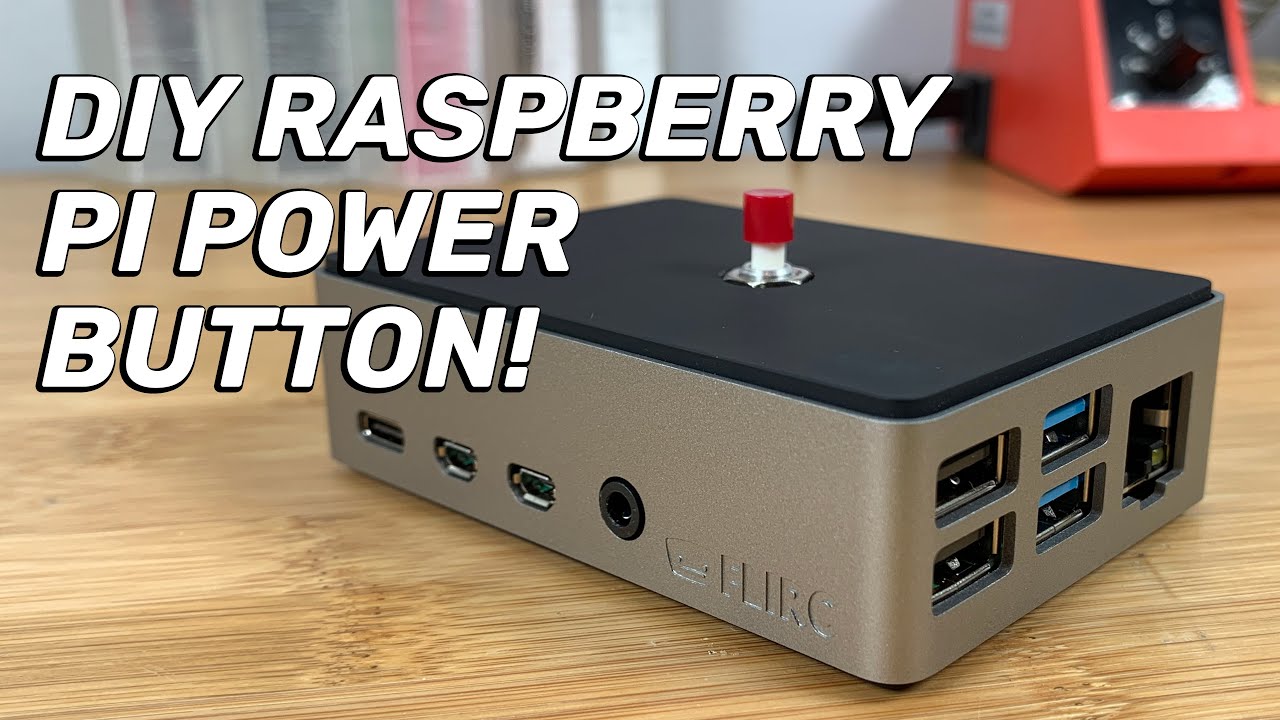
In this video, I'll teach you how to build your own Raspberry Pi power button, allowing you to shut your Pi down safely! I'll also show you how to install it in a FLIRC (or other Raspberry Pi) case. This will work with any Raspberry Pi model (Raspberry Pi 4, 3, Zero, etc.)
● View the full text/photo guide on howchoo:
https://howchoo.io/raspb...
olive haven
@somber yacht There's a row of labeled holes below the header on that board, the labels being the GPIO numbers. GPIO3 isn't one of them, but I don't think there's anything magic about that pin, as long as you change the code to match. Ground and power holes are below that -- you should just need one of the ground holes.
So you can wire the button between say GPIO5 on that top row and one of the ground pins right below it
somber yacht
@olive haven Thanks, i probably should have done a little bit more research before posting this! I thought shorting those pins was something built into the operating system/board to power on and off. Kind of like the power pins on a desktop motherboard. I looked into how the program works and your right. I can just switch to a pin thats not being used!
olive haven
I think 3's a popular choice for this kind of thing because it's right opposite a ground pin on the header.
civic rune
olive haven
I think 3's a popular choice for this kind of thing because it's right opposite ...
It also has a special wake functionality
So a Mom-On switch used there will shutdown and wake the pi
civic rune
Running into an issue with some test code I wrote that worked earlier but now is throwing errors when I swap the SD card to another pi.
Code is
def setup():
    GPIO.setmode(GPIO.BCM)
    for i in range(2,27):
        GPIO.setup(i, GPIO.OUT)
Error is:
/home/pi/testing.py:8: RunTimeWarning This channel already in use....
GPIO.setup(i, GPIO.OUT)
I didn't think that when coming from a cold start that any gpio would be in use.
Get that error when I run
import testing as t
t.setup()
 velvet frigate
you can ignore it, its a warning. if you want to disable warnings use
GPIO.setwarnings(False)
I saw that but I don't like to ignore warnings unless I have a deep understanding as to what they mean
halcyon relic
Hello, I need some help to get an output to an lcd with data coming from InfluxDB.
I have two sensors that feed a database. Grafana gets the data from there and I can watch it on my PC. I want to add a lcd so that I can also view the data without having to log into an PC.
I use a raspberry pi zero 2, two Adafruit BME280 and a Sparkfun SerLCd. Ask necessary drivers etc. are installed.
The code to read it the sensors works fine on it's own.
The sample code for the lcd works fine on it's own.
I can't code, my rough thinking was I can somehow merge these two codes, but that didn't work of course.
I'd appreciate it if anybody could guide me in the right direction on how and what code I need to embed into my sensor code to get it to display the data.
I uploaded the code here: https://gist.github.com/overcast7/bcb8bcff9e7e84f5dfaa6970c7ff7ed8

Gist
Adding code to feed an SerLCD with data from an influxDB - developer_sample_serlcd
olive haven
halcyon relic
Hello, I need some help to get an output to an lcd with data coming from InfluxD...
The basic thing is that since you don't have to do it all in a single program. You can run the sensors_to_influx.py as is, and write another program say influx_to_lcd.py that reads data from the database and displays it.
You can run the sensors_to_influx.py (or any other raspi program) in the background from the command line
python3 sensors_to_influx.py &. It'll print out something like [1] 20614 and then give you a command prompt. The [1] indicates that you can foreground the program by typing %1 at the command line.
(the 20614 is the OS process number for the program.)
halcyon relic
olive haven
The basic thing is that since you don't have to do it all in a single program. Y...
I'd be okay with that too, but my code-knowledge on how to grab the data from InfluxDB and put it on the lcd is too limited unfortunately
olive haven
Divide and conquer: do you know how to get data from InfluxDB?
I don't know that a particular DB, but I would think that the InfluxDBClient class contains methods to read data as well as to write it (as your code does with client.write_points)
What version of InfluxDB are you using?
halcyon relic
I'm not at the pi at the moment, I recall 1.6
But with your idea I found some good results online (keyword: querying) that I'll try in the evening
glacial gale
humble marsh
Here is an example of using `usb_cdc.data` to send data to a host computer. It's...
So, if i understand correctly, id set up buttons as shortcuts that would run code in a way similarly to repl
humble marsh
glacial gale
So, if i understand correctly, id set up buttons as shortcuts that would run cod...
I was just showing that example to show how to send data back to the host. The buttons were not so much the point: it's the use of usb_cdc.data.
btw, we have fixed the "b" problem in open(): https://github.com/adafruit/circuitpython/pull/5896 https://github.com/adafruit/circuitpython/issues/5895
glacial gale
humble marsh
btw, we have fixed the "b" problem in `open()`: <https://github.com/adafruit/cir...
So it will report the issue now? Or does it not register as an error at all so the script continues as normal?
humble marsh
glacial gale
So it will report the issue now? Or does it not register as an error at all so t...
it will report it as an error (which is what regular Python does).
glacial gale
kk
halcyon relic
Hey @humble marsh could you have a look at the code from two days ago for me? Im a bit proud that I now got three sensors working, but I have troubles figuring out the json_body fields
humble marsh
sure, upload it
halcyon relic
I saw that I had a SHTC3 laying around that I could use because its on address 0x70.
I then also used the adafruit drivers (in the old script it was a unoffical driver)
Bare with me, its not pretty. I just tinkered and got it working....
Line 44 is to stop it from flooding my Thonny
And well, the name fields I just added to see if I get all sensors in the output (with only the raw values it was impossible for me to check) I used this because I couldnt use (data.id) like before, since I didnt know how to address data
And because date = referred to code from the github BMW280 driver (which I no longer use)
So what I uploaded works and I get to display it in Grafana, but only one sensor of course since I got stuck
 real cipher
Hello, good morning/evening, I wanted to know if there is any way to boot the raspberry pi pico as autorun, thanks
 naive scarab
Good morning, I have found a new revision code c03115 which is causing me issues with trying to get neopixels to run. Could someone please open a PR for the relevant libraries? Thank you 😊
olive haven
real cipher
Hello, good morning/evening, I wanted to know if there is any way to boot the ra...
You can create a service which runs on boot. See https://www.raspberrypi.com/documentation/computers/using_linux.html#the-systemd-daemon. Or you can use cron to schedule a task on reboot: https://www.raspberrypi.com/documentation/computers/using_linux.html#running-a-task-on-reboot
olive haven
real cipher
Hello, good morning/evening, I wanted to know if there is any way to boot the ra...
Sorry, I see you asked about the Pico. Pico isn't a Raspberry Pi in the sense of a small computer that runs an operating system like Raspberry Pi OS. (This discussion group is about those computers and operating system.) The Pico is a microcontroller board that will run whatever software is loaded into its flash, like an Arduino sketch, or a Python interpreter like CircuitPython or MicroPython. Either of those Pythons have a way of specifying what Python code to run on boot.
 faint sparrow
I would ask in #help-with-arduino or #help-with-circuitpython wrt RP2040 boot automagic. ;)
Since it'd be hard to not autorun in Arduino sounds like a python question. I don't remember the deal on that.
@real cipher Earle Philhower's implementation for Arduino is usually a good choice for RP2040.
there's also an arduino.cc implementation, which is based partly on mbed ideas/code.
The cmake driven pico-sdk is another choice.
Plus at least two python implementations.
Like any other C/C++ program:
 soft sierra
Hi! I'm not sure what is the best place to ask this, but I'm having issues with a LSM9DS1 module, specifically with mki159v1, which isn't adafruit's, but is pretty similar. I'm not able to get it communicating via I2C to a Jetson Nano. i2cdetect detects the module on bus 1, on adress 6a and 6b. But I'm getting the error No I2C device at address: 0x1e, and looking around in the adafruit_lsm9ds1 library, I'm guessing that I'm also supposed to get a device detection at locations: 0x1c and 0x1e(for the magnetometer, perhaps?), which I'm not. Have I missed something? Currently, there are 4 pins connected to the module: Power Supply and Ground, and SDA, SCK for I2C. Am I doing something wrong?
faint sparrow
@soft sierra the i2c bus operates Open Drain.
That means you must use pullups or it won't work at all.
ruby night
I don't see any pull-up on the schematic https://www.mouser.com/datasheet/2/389/steval-mki159v1-1848591.pdf
soft sierra
faint sparrow
<@!683938395776352257> the `i2c` bus operates `Open Drain`.
I didn't see any mentions of this in the documentations I've been reading, with either the breakout, or the IMU
Can you direct me to some article related to this?
faint sparrow
I take your word on it that it's i2c. The i2c bus is as I've described it.
It's kind of a deep knowledge thing; I have no clear idea where you can validate my assertion.
ruby night
Some computer boards (Raspberry Pi) have I2C pullups installed on the board, but most Microcontrollers do not so eitehr they are on the sensor board or have to be added.
I don't know if the Jetson has them.
soft sierra
faint sparrow
I take your word on it that it's `i2c`. The `i2c` bus is as I've described it.
it definitely is i2c, with which I have next to none experience, causing this confusion
soft sierra
ruby night
<https://learn.adafruit.com/circuitpython-basics-i2c-and-spi/i2c-devices> fourt...
thanks a ton!
faint sparrow
If you add a second set of pullups (one set is hidden from your knowledge for any number of reasons) it'll probably still work okay.
soft sierra
ruby night
I don't know if the Jetson has them.
it doesn't, I'll have toadd it externally
faint sparrow
Once you add the pullups, and try it with and without them, you'll get a feel for it.
ruby night
10K is usually a good value for an I2C pull-up
soft sierra
faint sparrow
Once you add the pullups, and try it with and without them, you'll get a feel fo...
okay, thanks!
One thing that still confuses me though, is why am I getting some detection(accelerometer and gyroscope) on the right addresses(6a 6b)? If it shouldn't work, I shouldn't be getting any result, right?
faint sparrow
First guess is your firmware isn't error-detecting as certainly as it could.
Since the pullup is required, and you dont have it, the first thing to do is to have it. ;)
There's no point in asking questions about forks that you will not be traveling through. ;)
soft sierra
true, alright, I'll get that done and let you know if it works out. Thanks for the help @faint sparrow @ruby night
faint sparrow
;)
ruby night
Good luck!
faint sparrow
Getting a home-brew radio receiver working that first time is really hard; repairing it when it fails is comparatively easier. ;)
So get it working, then you are in the position to ask supplemental questions.
soft sierra
okay, there's progress! I'm now getting one of the two addresses that I wasn't getting(0x1c). Although the error is still the same. And it turns out, I wasn't reading the data sheet of the module as thoroughly as I thought I was. It did mention that I needed to pull out both the pins, which somehow went above my head.
olive haven
@soft sierra The Wikipedia article https://en.wikipedia.org/wiki/I²C is a good reference.
faint sparrow
can you read analog sensors with the proper HAT if so which ones?
and is it even a good idea with a mini-computer like the pi?
 umbral sable
I can't recommend a specific one, but an "ADC hat" is probably what you're looking for. Whether it's a good idea depends on the scope of the problem you're trying to solve. If you are reading a sensor and lighting up a LED in response, it's probably overkill. If you're reading a sensor and using it to automatically adjust the weather in a Minecraft server running on the Pi, that's much more reasonable, heh heh.
faint sparrow
I'm questionning wheter arduino and other microcontroller are obsolete now that most good sensors seems to be digital IC2
not sure why i'd even need analog anymore unless I'm using very cheap throwaway beginner sensors
when basically most chips will use analog inside and throw digital data
except for the real-time stuff I see the need for a microcontroller vs a pi less and less as time pass
and even for real-time good sensors have a readings history in them
it seems unless you are doing ham or audio you don't really need analog
umbral sable
It's all a sliding scale of features versus cost and power consumption. There's a whole spectrum of chips from 8-bit MCUs up to GHz MCUs and into embedded CPUs. Nothing's really going obsolete, just optimized for different purposes.
turbid rivet
While many sensors have, in fact, come with more digital interfaces today, there are still a slew of applications where having an ADC onboard is far more cost-efficient than designing with the digital ICs.
I can also say from personal experience that using an ADC is far more robust of a system than relying on everything I2C/SPI...
If not for the efforts of manufacturers like Adafruit or Raspberry Foundation making these digital interfaces so much more accessible, we might still be restricted to analog sensors for a lot of personal development, even today.
 stuck quarry
Is this the wrong place to get help with RP2040?
 lost wolf
stuck quarry
Is this the wrong place to get help with RP2040?
lost wolf
stuck quarry
Is this the wrong place to get help with RP2040?
Kind of. What language are you using it with?
turbid rivet
I think we've been kinda loose about it, since it technically has Raspberry Pi in the name, but this channel is usually browsed by people more familiar with the single-board computer type of Pi.
lost wolf
This is more for Raspberry Pi single board computers.
turbid rivet
You usually find better help with those in the software help channels or the project help channels, where Arduinos and other microcontroller projects are more common.
stuck quarry
Well I tried with python because setup was so easy but really wanted to use C, and I'm wondering what people's thoughts are on using the unofficial Arduino support because I can't for the life of me get it to run C based on the official documentation, particularly on a Windows machine.
stuck quarry
turbid rivet
You usually find better help with those in the software help channels or the pro...
TY Hem. I'm new here. Can you suggest a specific channel based on my above statement?
lost wolf
stuck quarry
TY Hem. I'm new here. Can you suggest a specific channel based on my above state...
Welcome! I would suggest #help-with-projects.
And we use the Philhower Pico Arduino core. It's pretty solid at this point.
I'm in the middle of adding usage to all of the RP2040 guides, as it happens.
stuck quarry
Oh cool! Can you point me to any of the docs you are working on, or a preview of they are not yet live? Pretty new to all this but I've found the Arduino tooling surprisingly awesome and intuitive.
lost wolf
@stuck quarry What RP2040 board are you using?
Depending on which board, I can point you to a guide for a different board which obviously wouldn't be specific to your board, but it's easy enough to figure out what to do based on the info. However, if I've already done it for your board, even easier.
stuck quarry
Feather RP2040 because it's a really cool board and I happened to get two of them free with Adafruit orders during the promotions.
lost wolf
OK, I haven't completed Feather yet. Let me get you a link to another guide.
stuck quarry
Ok thank you so much!
lost wolf
It will be the same process, but pick Feather RP2040 instead from the menus.
I don't have a lot of Arduino experience, so you're lucky to have caught me in the middle of something I actually have an answer for 😄
stuck quarry
I certainly do feel lucky!
lost wolf
@stuck quarry The ItsyBitsy is actually a good example, because the standard I2C pins are WIRE1 on the Feather as well, versus WIRE. The STEMMA QT connector on the Feather is WIRE. It's a bit of a gotcha compared to other Arduino boards. Anyway, good luck! Ask any further questions in #help-with-projects or #help-with-arduino.
And you only need to post in one channel. 🙂 Folks who are able to respond will see it.
faint sparrow
As far as I know, all the RP2040 sdk ports leverage the pico-sdk so in that sense they're 'wrappers' to the factory supported SDK.
That means all the cool stuff is available.
Most follks will go Earle Philhower and call it a day, unless python is wanted.
stuck quarry
lost wolf
<@!634191753003663374> The ItsyBitsy is actually a good example, because the sta...
Thank you so much!
 vale ferry
bit of an RPi newbie here, which pin is board.D5?
And where can I find a list of all of the boards
*pins
My code:
import adafruit_max31855
from digitalio import DigitalInOut
import board
spi = board.SPI()
#this declares which of the pins are used to enable the chip
cs = DigitalInOut(board.D5)
sensor = adafruit_max31855.MAX31855(spi, cs)
print(sensor.temperature)
However I think that this is working because the Chip Select on my device is low/not connected. Which pin would board.D5 end up being?
ruby night
The comprehensive add-on boards & GPIO Pinout guide for the Raspberry Pi
D5 refers to GPIO 5
there are lots of pin numbering conventions for the Pi so be careful
vale ferry
Okay so changing to D8 should use GPIO8?
ruby night
yes
vale ferry
thanks!
ruby night
You're welcome
civic rune
Running into strange behavior. When I run my GPIO setup method:
def setup():
    GPIO.setmode(GPIO.BCM)
    for i in range(2,27):
        GPIO.setup(i, GPIO.OUT)
And then run
for i in range(2,27):
     print(i, GPIO.input(i))
I get all 0s as expected except for two pins: 7 and 8, those show as 1
anyone have any clues?
Here GPIO is RPi.GPIO
steady rose
@civic rune floating input issue
civic rune
What do you mean?
steady rose
need to enable internal pull up/down resistors
depending on what is wired and how to the pins
also, you configured for output
civic rune
I intended to configure for output. The second bit of code is the only way I know to get the state of a pin
I assumed when you configured the pins as outputs they would default low
 dapper steppe
Can anyone tell me where to find the physical dimensions on the Adafruit MacroPad RP2040? Sorry if wrong forum for this question.
tired marsh
dapper steppe
tired marsh
there is that: <https://www.adafruit.com/product/5100#tab-technical-details-head...
Thanks. No idea why it didn't load the details on the product page when I went there before...
tired marsh
for height of the whole enclosure I'm not sure how to evaluate that
dapper steppe
no worries, I'm considering using it as part of a guitar build, so the guitar is going to be the enclosure and it'll act like a midi controller.
again, thanks for the links.
tired marsh
oh interesting idea
halcyon relic
Hi, I have a display that I just write code for to get it to display temperature and humidity readings. It works, but it shows way too much decimals. How can I tell it to only show one, like 40.1°C? Currently I have:
lcd.setCursor(0, 0)
lcd.print(f"T:{temperature_celsius} C RH:{humidity} %")
lcd.setCursor(0, 1)
lcd.print(f"P:{pressure_hpa} hPa ")
looks like you're using f-strings:
https://docs.python.org/3/tutorial/inputoutput.html#formatted-string-literals
add a : and then use format spec:
https://docs.python.org/3/library/string.html#formatspec
>>> import math
>>> math.pi
3.141592653589793
>>> print(math.pi)
3.141592653589793
>>> print(f"pi = {math.pi}")
pi = 3.141592653589793
>>> print(f"pi = {math.pi:5.3f}")
pi = 3.142
>>>
Thats what I googled too, but I figured it out by:
data.temperature = round(data.temperature, 1)
data.humidity = round(data.humidity, 1)
lcd.setCursor(0, 0)
lcd.print(f"T:{temperature_celsius} C RH:{humidity} %")
lcd.setCursor(0, 1)
lcd.print(f"P:{pressure_hpa} hPa ")
😃

 snow aurora
halcyon relic
Hi, I have a display that I just write code for to get it to display temperature...
snow aurora
halcyon relic
Hi, I have a display that I just write code for to get it to display temperature...
What libeary do you use for that?
halcyon relic
You mean language?
You need a "driver", something like this:
https://github.com/sparkfun/Qwiic_SerLCD_Py

GitHub
Python module for I2C control of the SparkFun Qwiic Serial LCDs - GitHub - sparkfun/Qwiic_SerLCD_Py: Python module for I2C control of the SparkFun Qwiic Serial LCDs
halcyon relic
snow aurora
What libeary do you use for that?
Then you can create a file "example.py" and open it with something like Thonny. There you can write the code and hit play
 supple coyote
Low distortion, no fisheye, lenses that can do 90 degrees. Anyone have any ideas?
umbral sable
supple coyote
Low distortion, no fisheye, lenses that can do 90 degrees. Anyone have any ideas...
In a weird coincidence, I was at an optics trade show this week, and one booth had a flyer specifically about their low-distortion lenses: https://sunex.com/2019/11/22/tailored-distortion-distortion-correction-at-speed-of-light/
supple coyote
Well that’s convenient , thanks!
faint sparrow
hello, ive been wanting to try out the pi pico with circuit python. but i never understood the pins
like do we just connect any jumper cable to any GPIO and it works the same
or is there like more detailed stuff
is there like a tutorial or a webpage that teaches the different pins
and their functions
faint sparrow
hardy plaza
https://cdn-learn.adafruit.com/downloads/pdf/getting-started-with-raspberry-pi-p...
thank you :)
hardy plaza
faint sparrow
thank you :)
You're welcome. For any microcontroller it's also good to locate a graphical version of its pinout, very handy...

The reason each pin has the different colored options is that most pins can be configured for different purposes, via software.
faint sparrow
hardy plaza
so lets say i have an led
can i plug that into any GPIO and GND pin?
sorry if im asking like really nooby questions
im just really new to the pico and a curious person by nature
hardy plaza
faint sparrow
so lets say i have an led
can i plug that into any GPIO and GND pin?
Yes, you can connect an LED (in series with a suitably-sized resistor) between a GPIO pin and ground, noting that the maximum current of all the GPIO pins must be less than 50mA, as according to the FAQ: https://datasheets.raspberrypi.com/pico/raspberry-pi-pico-faq.pdf
I'm not sure what the maximum current is per pin, but on the Raspberry Pi it's 16mA, so you need to choose LEDs that don't consume more than around that limit. GPIO pins in output mode are generally meant as signal rather than power drivers, but LEDs are (generally) pretty low current devices.
wintry apex
fickle shard
seems like a text encoding issue, but thats all i know
Thanks - looks like that to me, as well. Not sure how to fix it. I just changed themes for now. Definitely not a show stopper.
 scarlet latch
Hey guys, i have a small class I created to control a furance. I am just turning a relay on and off that controls my furnace. I wrote the status method to check if it is currently on. However I feel like I should actually check the status of LED(17). Is that possible? Incase it somehow was left on from an old program or something of the sorts. Since it is a furnace I want to be sure.
class furnace:
    def __init__(self):
        self.relayOutput = LED(17)
        self.relayOutput.off()
        self.enabled = False


    def enable(self):
        self.relayOutput.on()
        self.enabled = True

    def disable(self):
        self.relayOutput.off()
        self.enabled = False

    def status(self):
        if self.enabled == True:
            return True
        else:
return False```I mean you set the status explicitly in init, no? Seems fine
civic rune
I'm no expert. I've been writing Python for a few years but no expert. I think you're ok
 opaque wagon
btw you can rewrite you status func as so:
def status(self):
    return self.enabled
because self.enabled is already a boolean
and if you want to make sure it's exactly True, not just truthy, use if self.enabled is True
civic rune
I prefer explicit checks because of how soft typing is in Python.
But that's just me
Trying to make Python C
And rhyming by mistake
If you never assign to self.enabled anything but a boolean, you're fine, and for small projects it's probably never a concern.
opaque wagon
in later versions of python (3.9 i'm pretty sure) you can add types to your functions:
def status(self) -> bool:
    return self.enabled
and you can also add them to parameters as well
you can also do it to variables as well i'm pretty sure but then it gets ugly
like
self.enabled: bool = False
Interesting
umbral sable
Note that the type annotations are just "hints" that can be checked by separate tools, not enforced by Python at run-time.
civic rune
Yeah that's what I thought
If you want strict typing, you should use a different language
olive haven
But it's incredibly useful documentation, hints tool or no
civic rune
True
olive haven
You can do it in CP -- it seems like the parser implementation is that it allows, but ignores, the ": blah" and "-> blah" stuff
It seems the CP folks are gradually adding type hints all over the place
 west sierra
Looking for some wisdom and opinions. For a vehicle install of a power management/monitoring system, why would I use an RP2040 Pico or similar instead of a Raspberry Pi Zero 2 W? Power draw? Better sleep performance/power usage? Can someone explain?
umbral sable
The power draw would definitely be one angle. The Pico has ADC inputs, if you need those, and is generally going to be more adept with low-level digital interfaces, PWM timers, etc... anything more real-time focused.
west sierra
So, it would be better at UART serial connections for RS485/232?
Or, is that still comparable to the Zero 2 W?
umbral sable
UARTs are common enough that the Zero would also be fine at that, but the Pico has a more flexible I/O system for more unusual things like, say, Neopixels.
west sierra
All this guy would need to do is communicate with some modbus things, collect some stats from sensors, and run a display in the cab of my truck.
umbral sable
The main reason to use a Zero would be for the wireless, or for access to the more flexible software resources you get with a full Linux environment and a CPU with plenty of memory and processor power.
west sierra
And turn on/off some FETs.
umbral sable
The display would also be a reason to go with the Zero, if it's something like a complex graphical interface on a HDMI screen, etc.
west sierra
Yeah, that's what I was going for. I have this suuuuuper-wide TFT that I was going to build a cyberdeck out of my 400 with, but I am thinking, it's narrow enough to fit perfectly to be mounted on my dash.
umbral sable
That's going to be a better choice, then. The Pico is pretty RAM-limited, so the type of displays it can deal with comfortably is also limited.
umbral sable
That I'm not sure of offhand. It would certainly have some sleep modes, but precisely what can wake it from different levels is outside my expertise.
west sierra
Totally cool, I will do some research on those bits! Thank you for being here and providing assistance. I truly appreciate all of you.
hardy plaza
umbral sable
Note that the type annotations are just "hints" that can be checked by separate ...
I came to this discussion a bit late, but I'm guessing you're both aware that you can do explicit type checks:
    if isinstance(arg, MyClass):
        self._arg = arg
    else:
        raise TypeError('expected MyClass, not {}'.format(type(arg)))
Whenever I'm not entirely sure the right argument might get passed I add a type check, or when I'm permitting different classes of arguments I'll handle them according to the check.
 indigo basin
Hello, real VNC is not connecting even though i can ping the pi. i'm getting:
Timed out waiting for a response from the computer
anyone else had this problem? it's been a while since i used VNC, but i've never had a problem before.
indigo basin
yes
when connected via SSH and i enter:
vncserver :1
i get:
Error: A VNC or X Server is already running as :1 [DisplayInUse]
i'm using the recommended client on windows
one variant- my ethernet cable is plugged directly from my computer to the pi. my understanding is that there's really no problem with this- newer adapters manage crossover and IP address negotiation, and again, i can ping and SSH
ripe berry
I had that happen to two of my Pi's, and I had to delete them from the Windows VNC client and re-enter them. Worked fine after that.
indigo basin
weird... this is the first time using, and i don't realy know how i'd 'delete' them- it's just an IP address in the address bar- no address book or anything
realvnc troubleshooting page states:
"Check the remote computer is switched on. Ensure antivirus software lists VNC Server as an exception, and the firewall is configured to allow access on VNC Server’s listening port (5900 by default)."
i'm using "Raspbian GNU/Linux 11 (bullseye)" which i don't know if it automatically runs a firewall or antivirus
indigo basin
fyi got it- rebooting cleared the error, and then i got a message stating the ip address of the desktop, but specifying the port number, which was not 5900 as implied by the error note above, but i was able to simply add the port number to the IP address in the vnc viewer and it worked
 static sparrow
I am working with the AHT20 temp and humidity sensor. The example code on adafruit site uses “board” library. When I run the example code , I get an error for I2C. So I went to REPL I imported board and did the dir(board) . The I2C wasn’t in the list.
civic rune
You mean you get an error when you run
var = board.I2C()?
static sparrow
Yes
civic rune
Hm
I mean you can always do the other way of setting up I2C
Let me see if I can find it
civic rune
static sparrow
Yes
Was there a board.SCL and a board.SDA?
olive haven
What is board.board_id?
static sparrow
SPDX-FileCopyrightText: 2021 ladyada for Adafruit Industries
SPDX-License-Identifier: MIT
"""
Basic AHTx0 example test
"""
import time
import board
import adafruit_ahtx0
Create sensor object, communicating over the board's default I2C bus
i2c = board.I2C() # uses board.SCL and board.SDA
sensor = adafruit_ahtx0.AHTx0(i2c)
while True:
print("\nTemperature: %0.1f C" % sensor.temperature)
print("Humidity: %0.1f %%" % sensor.relative_humidity)
time.sleep(2)
That is what I’m using on a PI zero
I’m not at my computer to answer questions right now
static sparrow
civic rune
i2c = busio.I2C(board.SCL, board.SDA)
I will try this when I get home
olive haven
static sparrow
That is what I’m using on a PI zero
I just set up Blinka on a Pi Zero W, following the instructions at https://learn.adafruit.com/circuitpython-on-raspberrypi-linux/installing-circuitpython-on-raspberry-pi. When I import board, dir(board) shows I2C in the list.
>>> import board
>>> dir(board)
['CE0', 'CE1', 'D0', 'D1', 'D10', 'D11', 'D12', 'D13', 'D14', 'D15', 'D16', 'D17', 'D18', 'D19', 'D2', 'D20', 'D21', 'D22', 'D23', 'D24', 'D25', 'D26', 'D27', 'D3', 'D4', 'D5', 'D6', 'D7', 'D8', 'D9', 'I2C', 'MISO', 'MISO_1', 'MOSI', 'MOSI_1', 'RX', 'RXD', 'SCK', 'SCK_1', 'SCL', 'SCLK', 'SCLK_1', 'SDA', 'SPI', 'TX', 'TXD', '__blinka__', '__builtins__', '__cached__', '__doc__', '__file__', '__loader__', '__name__', '__package__', '__repo__', '__spec__', '__version__', 'ap_board', 'board_id', 'detector', 'pin', 'sys']
>>> board.board_id
'RASPBERRY_PI_ZERO_W'
Hmm, I will double check and share what I find.
static sparrow
olive haven
I just set up Blinka on a Pi Zero W, following the instructions at <https://lear...
Python 3?
olive haven
yes
static sparrow
Ok
olive haven
It's best not to use Python 2 for anything unless you absolutely have to. It's "legacy code", as the euphemism has it.
 nova oyster
Hey all. I am trying to get the https://www.adafruit.com/product/4741 working on my raspberry pi 4. I followed the tutorial at https://learn.adafruit.com/circuitpython-on-raspberrypi-linux/installing-circuitpython-on-raspberry-pi first then the tutorial on the display itself. When I run the sample code at https://learn.adafruit.com/adafruit-grayscale-1-5-128x128-oled-display/circuitpython-wiring-and-usage I get the following error message about displayio:
This OLED goes out to all the fans who want more pixels! Normally our 128x64 OLEDs are the biggest ones we've stocked that can use I2C. This one is a whopping 128x128 pixels and it even ...

Adafruit Learning System
Make hardware and interface with sensors super easy using CircuitPython

Adafruit Learning System
This cute little OLED is twice the size of out 128x64 OLED, plus it can do shades of grey.

I spent a while looking into it and from what i understand displayio is supported on the pi 4. Not sure what to do next. Thanks.
static sparrow
olive haven
I just set up Blinka on a Pi Zero W, following the instructions at <https://lear...
Python 3.7.3 (default, Jan 22 2021, 20:04:44)
[GCC 8.3.0] on linux
Type "help", "copyright", "credits" or "license" for more information.
import board
dir(board)
['BaseDimension', 'Board', 'Dimension', 'Empty', 'Image', 'InfiniteDimension', 'Infinity', '_Empty', '_InfiniteDimension', '_Infinity', 'builtins', 'cached', 'doc', 'file', 'loader', 'name', 'package', 'spec', '_centred_coord', 'cornerposts', 'functools', 'imagefile_sprite', 'io', 'itertools', 'long', 'os', 'sys', 'text_sprite']
board.board_id
Traceback (most recent call last):
File "<stdin>", line 1, in <module>
AttributeError: module 'board' has no attribute 'board_id'
olive haven
static sparrow
Python 3.7.3 (default, Jan 22 2021, 20:04:44)
[GCC 8.3.0] on linux
Type "help",...
I don't know what that's from -- before I installed the Blinka/CircuitPython stuff, 'import board' found no 'board' module -- but it's not anything that the Blinka installation would have set up.
 static sparrow
How do install what I need?
civic rune
Idk if you need to uninstall the board you installed first, I would
But one sec, let me get you the link
https://learn.adafruit.com/circuitpython-on-raspberrypi-linux/installing-circuitpython-on-raspberry-pi @static sparrow
Adafruit Learning System
Make hardware and interface with sensors super easy using CircuitPython
 unborn rapids
why do i always end up on the CIRCUITPY drive when i unplug my raspberry and plug it back in
olive haven
nova oyster
I spent a while looking into it and from what i understand displayio is supporte...
Theoretically you can install it with pip. (See https://pypi.org/project/adafruit-blinka-displayio/.) I tried that, and though the install succeeded, I got an error trying to import it in Python:
>>> import displayio
Traceback (most recent call last):
  File "<stdin>", line 1, in <module>
  File "/usr/local/lib/python3.9/dist-packages/displayio/__init__.py", line 23, in <module>
    from ._bitmap import Bitmap
  File "/usr/local/lib/python3.9/dist-packages/displayio/_bitmap.py", line 23, in <module>
    from PIL import Image
  File "/usr/local/lib/python3.9/dist-packages/PIL/Image.py", line 89, in <module>
    from . import _imaging as core
ImportError: libopenjp2.so.7: cannot open shared object file: No such file or directory
I tried sudo apt install libopenjp2-7, which succeeded, but then I got a different error. FWIW the adafruit-blinka-displayio version is 0.8.0, so maybe not ready for prime time?
scarlet latch
Has anyone run two scripts on a single raspberry PI with paho MQTT. When the second script starts. they seem to both have connection issues, but independently they can both run.
I have both scripts working independently but still having client issues
unborn rapids
If some one help me with my raspberry pi problem I pay him :0
west sierra
unborn rapids
If some one help me with my raspberry pi problem I pay him :0
What do you need help with?
 thin wagon
Hi, I'm stuck with the installation of .net 5 on my raspberry pi, it notes that it has been installed but whenever I ran 'dotnet' it said segmentation fault, anyone know what the issue could be?
snow aurora
hey guys, i used to have a small handheld fan. i have lost it's controlling board. now i have the fan itself which has 2 wires now coming out of it. can i use Pico to make it function?
civic rune
snow aurora
hey guys, i used to have a small handheld fan. i have lost it's controlling boar...
Do you have a product number for the fan?
snow aurora
civic rune
Do you have a product number for the fan?
it just has a series number
it says input voltage should be 5 volts
civic rune
Might be a PWM controlled fan, I don't think you can just use a pico
 split token
would anyone in this channel know what's going on here? link to post in #help-with-circuitpython #help-with-circuitpython message
 elfin vigil
Hey all so I recently updated one of my Raspberry Pi 4B's with the rpi-update and now it won't boot. I think it's the new firmware that was installed. I have reflashed the latest image and it still won't boot. What can I do?
 zealous seal
elfin vigil
Hey all so I recently updated one of my Raspberry Pi 4B's with the rpi-update an...
zealous seal
elfin vigil
Hey all so I recently updated one of my Raspberry Pi 4B's with the rpi-update an...
May or may not help - had a pi 4 that worked..then one day didn't... reflashed the card a bunch of times and still didn't and gave up... a year later I tried a different card and it worked.
ripe berry
You probably can just try a new card without waiting a year 😉
elfin vigil
I could try, but the card that made it not work works in my other RPi 4. Also, does anyone know if NetPi Plus works on the RPi4?
 plush wave
Hi there I'm making a rotary encoder to operate my commands on software but I need to use the keyboard hid coding.
I've been able to code it fine but when I turn the rotary encoder it sometimes goes back on the numbers.
For example 1,2,3,2,3,4,5,4,3.
Something like that. Any ideas
turbid rivet
Could be mechanical bouncing on some edges, or turning the encoder faster than the edges are scanned?
plush wave
I think it is mechanical as I'm going slow is there away to stop this in the coding
plush wave
anyone else have any ideas
umbral sable
plush wave
anyone else have any ideas
If it's switch bouncing, the usual approach is a "debouncing" algorithm in software, which is often as simple as waiting a few milliseconds for the value to stabilize before reporting it as real.
 whole sinew
What are the modules of choice for using gpio/spi/i2c in python?
plush wave
umbral sable
If it's switch bouncing, the usual approach is a "debouncing" algorithm in softw...
how do i get around it debouncing is not a part of coding im used to
 plush wave
umbral sable
https://learn.adafruit.com/debouncer-library-python-circuitpython-buttons-sensor...
plush wave
umbral sable
https://learn.adafruit.com/debouncer-library-python-circuitpython-buttons-sensor...
had a look and it doesn't have an example for HID
glacial gale
i cant get my pi to connect to the internet and my instructor cant figure it out. can someone help?
scarlet latch
Hey Guys, Im having a strange issue. I have always connected to a DB at the start, then querried as needed. However for some reason if I have my database connection outside my loop I am not reading in the latest data. If the connection is inside the main loop it works fine. However I dont feel like I should be creating a new connection every query.
import mariadb
import sys
from datetime import datetime, timedelta
Database Script
class furnaceDB:
    def __init__(self, db):
        self.conn = mariadb.connect(
            user="pi",
            password="Skylar2305!",
            host="localhost",
            port=3306,
            database=db
        )
        self.cur=self.conn.cursor()
        print("Sucessfully Connect To Database")

    def readSensor(self,sensor, datetime):
        sql = ("""SELECT * FROM garage WHERE sensor = %s AND time > %s""")
        data = (sensor,datetime)
        self.cur.execute(sql, data)
        results = self.cur.fetchall()
        return results
Control Script
while True:

    currentTime = datetime.now()
    windowTime = timedelta(minutes = 5)
    checkTime = currentTime - windowTime

    #Connect To Database
    database = furnaceDB("furnace")  #@@@ This is the spot that If I move outside the Loop I get old data
    setpoint = database.readSetpoint()
    results = database.readSensor("garage1", checkTime)

    if len(results) == 5 or len(results) == 4: # Make sure we read 4 or 5 datapoints at least
        tempBuffer = 0.0
        for result in results:
            tempBuffer = result[1] + tempBuffer

        avgTemp = tempBuffer/len(results)
        shutdownError = False
        print(f"Setpoint: {setpoint}  5 Min Temp: {avgTemp}, Read Time {currentTime}")

    else:
        shutdownError = True
        print(f"Incorrect Amount Of Datapoints Available. Setpoints Read: {len(results)}")

    if shutdownError == False:
        if avgTemp < setpoint:
            print(f"Turning On Furnace")
            client.publish("garage/furnace1/control", "True")

    sleep(60)
You may need to connect directly to your router with an ethernet cable to set it up.
glacial gale
i fixed it. thanks 🙂
ripe berry
What was the solution?
glacial gale
Turn off my pc
civic rune
Is there anything special about GPIO 7 such that it would be output-high on boot?
turbid rivet
civic rune
Is there anything special about GPIO 7 such that it would be output-high on boot...
I believe GPIO 0-8 have pullups enabled by default, so I wouldn't be surprised if those pins all had output-high on boot.
civic rune
Hmmm.
 civic rune
I'm unclear on the circuitry of this system, and I'm disinclined to sort it out since it's all being replaced, but I'm only seeing a "high" state on the circuit connected to GPIO 7
 restive jungle
Hey can I connect my Xbox controller to my pi
turbid rivet
restive jungle
Hey can I connect my Xbox controller to my pi
Yes. you can.

Howchoo
This guide covers the process of connecting different Xbox controllers to a Pi. Wired and wireless Xbox 360 and Xbox One controllers work with the Raspberry Pi.
restive jungle
Kk thx
restive jungle
So snool problem
 sharp timber
Hi There, I just bought the AIY Vision kit from Google on Adafruit and can't wait to start my project. I wonder if anyone has any ideas that could help me. I have never done any computer vision or AI before, but this goal seems achievable. I want to write a python program that will take a baseline picture of my kids' bedroom from above with a clean floor, the continuously watch it and calculate the % messy by presumably subtracting the original background image from the camera image and then calculating the % of the image that is left. I will have a button to "rebaseline" and will use a servo to create an oldschool analog dial to show % messy. Any ideas on the python vision code? similar example links?
 astral echo
Hello, I'm using PI4 with circuitpython bare metal port. I have connected an HDMI display but can't see any anything on display. Is the REPL visible on USB or HDMI?
umbral sable
sharp timber
Hi There, I just bought the AIY Vision kit from Google on Adafruit and can't wai...
The go-to for vision tasks like that would probably be the OpenCV library. It has Python bindings too.
sharp timber
umbral sable
The go-to for vision tasks like that would probably be the OpenCV library. It ha...
Thank you. That is what I am finding online too. Others have also suggested Yolov5
umbral sable
My instinct would be to stick with more basic computer-vision operations rather than a full AI model for the problem as you've described it. The latter would generally require you to collect a big dataset to teach the AI what clean and messy rooms look like. "Okay, here's a photo of the kid's room at 13% messiness. Here's one at 28% messiness..."
astral echo
anyone has experience with Pi 4 and bare metal python?
faint sparrow
afaik you connect up to TX/RX pair on the RPi4 pin headers.
Just looked. It's only for debugging after modifying C source so not normal use.
Normal use on RPi4 is the USB-C cable connection.
 solar phoenix
Hi, I have a problem with my Raspberry Pi Pico. I downloaded CircuitPython for the first time and everything worked fine until I reconnected it. I only had one file there and the others don't show up. I tried to reinstall CircuitPython, but I still only have boot-out.txt and the lib folder and others do not appear. Does anyone know how to fix this? Thanks!
 rotund pivot
@solar phoenix it may not a problem, you can load a code.py . But safest is to nuke the flash, then reload Circuitpython and your other files.
bottom of this page: https://learn.adafruit.com/adafruit-feather-rp2040-pico/circuitpython
(CircuitPython questions will get more traction in #help-with-circuitpython )
astral echo
solar phoenix
Hi, I have a problem with my Raspberry Pi Pico. I downloaded CircuitPython for t...
are you using bare metal or with linux?
solar phoenix
Without linux
astral echo
I'm too using without linux but i cant see anything on my HDMI
did you edit boot.py?
solar phoenix
I only downloaded the CircuitPython on it, put adafruit hid in the lib folder and putted payload on it. After that it was working fine and like 10 mins later this happend.
astral echo
did you download .zip file from downloads page? or you used .img file?
solar phoenix
i used the zip
astral echo
i think there was a similar issue in its repo issues
solar phoenix
Okay thanks, i manage to nuke it and its working now
Is it bad to nuke the raspberry pi pico often?
faint sparrow
You won't be able to wear out the QSPI flashROM chip.
You'll lose it in a pile in the attic, damage it by overcurrent through Vcc/GND or something else way before you'll use the last cycle of the QSPI flashROM' s lifespan. ;)
steady rose
Raspberry Pi Pico is not the same as Raspberry Pi SBC's (like Pi 4)
just fyi, seems like two different issues
sharp timber
umbral sable
My instinct would be to stick with more basic computer-vision operations rather ...
That is exactly what I want to avoid
faint sparrow
can i run the pico by connecting the usb to a power brick or a battery pack?
It wants up to 1.6 Amps during startup.
After that about 800 mA maybe.
Might spike up to about 1.3 A occasionally.
turbid rivet
faint sparrow
It wants up to 1.6 Amps during startup.
I believe this is the Pico, not a Zero.
turbid rivet
faint sparrow
can i run the pico by connecting the usb to a power brick or a battery pack?
Yes.
faint sparrow
KD3005D from Korad
(https://www.sra-solder.com/korad-kd3005d-precision-variable-adjustable-30v-5a-dc-linear-power-supply-digital-regulated-lab-grade)
Setup to current-limit an RPi4. That was my thought. ;)
The RPi4 would boot reliably somewhere north of 1250 mA iirc.
Then settle down to 800 mA.
An RP2040 board would draw far less.
rotund pivot
faint sparrow
can i run the pico by connecting the usb to a power brick or a battery pack?
Some USB battery packs will turn off if not enough current is being drawn. There's a dongle for that. Or find one that doesn't.
faint sparrow
Figure 35 mA for the average target board at quiescence (idling in a while(-1);).
solar phoenix
faint sparrow
You'll lose it in a pile in the attic, damage it by overcurrent through Vcc/GND ...
Okay, thanks:)
faint sparrow
I am trying to make a clock with my Raspberry Pi Pico and i2c display. Can anyone help me code it? (python or circuit python)
turbid rivet
faint sparrow
I am trying to make a clock with my Raspberry Pi Pico and i2c display. Can anyon...
https://learn.adafruit.com/circuitpython-display-support-using-displayio/text might be a good place to start. What exactly are you stuck on?

Adafruit Learning System
User friendly guide to CircuitPython's native display library - displayio.
faint sparrow
turbid rivet
https://learn.adafruit.com/circuitpython-display-support-using-displayio/text mi...
I really am just clueless with micropython and circuitpython. this project is due tommrow and Im freaking out
@turbid rivet
umbral sable
Step one would be to get some example code running on your hardware, just to make sure your wiring is sane and you understand the general flow to get code onto it. Then some example code specifically for your display, to make sure that part works. Then you can start to figure out what functions you need to create a clock, which could be simple ("12:00" text) or complex (animated analog clock face), etc.
 cunning gazelle
faint sparrow
I really am just clueless with micropython and circuitpython. this project is du...
cunning gazelle
faint sparrow
I really am just clueless with micropython and circuitpython. this project is du...
I'd start by trying to draw lines and circles
faint sparrow
umbral sable
Step one would be to get some example code running on your hardware, just to mak...
can I see some sample code of writing text
umbral sable
faint sparrow
can I see some sample code of writing text
You mean like the tutorial that @turbid rivet linked a couple of messages up? 😉
faint sparrow
I have a feeling Im gonna need lots of help 😭
faint sparrow
@umbral sable the pi pico does not have a onboard screen. So I purchased an i2c screen. So the example code wont work
umbral sable
Do you have some different example code targeting that screen model?
faint sparrow
umbral sable
Do you have some different example code targeting that screen model?
no I do not, heres the i2c I bought https://www.amazon.com/dp/B019K5X53O?ref=ppx_yo2_dt_b_product_details&th=1

Introduction As we all know, though LCD and some other displays greatly enrich the man-machine interaction, they share a common weakness. When they are connected to a controller, multiple IOs will be occupied of the controller which has no so many outer ports. Also it restricts other functions of...
umbral sable
Possibly a tutorial like this would be compatible with it. https://lastminuteengineers.com/i2c-lcd-arduino-tutorial/

Last Minute Engineers
Learn to control I2C LCD with Arduino along with pinout, wiring, finding I2C address, adjusting contrast, arduino code, create and display custom characters
faint sparrow
umbral sable
Possibly a tutorial like this would be compatible with it. https://lastminuteeng...
I dont get it
umbral sable
Oh, sorry, you were working in CircuitPython, not Arduino. My bad...
faint sparrow
umbral sable
Oh, sorry, you were working in CircuitPython, not Arduino. My bad...
yeah..
umbral sable
You may want to ask in #help-with-circuitpython , as I'm less familiar with the particular library you might need to use with that display. (You would probably have a friendlier situation if you bought an Adafruit display instead of a random Amazon part without an associated tutorial.)
faint sparrow
umbral sable
You may want to ask in <#537365702651150357> , as I'm less familiar with the par...
which display do u reccomend
umbral sable
There are lots, so it just depends on your requirements for size, resolution, color, whether you need text or graphics, etc. I think Adafruit has a similar 16x2 character LCD, for example.
faint sparrow
I just need it to be able to display time
 keen cipher
@everyone how would I connect an 18 pin ribbon cable display to a 15 pin raspberry pi DVI display port ?
civic rune
keen cipher
@everyone how would I connect an 18 pin ribbon cable display to a 15 pin raspber...
Don't @ everyone
west sierra
keen cipher
@everyone how would I connect an 18 pin ribbon cable display to a 15 pin raspber...
So. You just jumped into every channel possible and ran an @ everyone? Let's contemplate. What did you think would happen?
civic rune
west sierra
So. You just jumped into every channel possible and ran an @ everyone? Let's con...
Fortunately it's turned off but it's still not good practice
It's like running into a room and screaming at the top of your lungs
west sierra
I'm not even going to say anything, because I would only incriminate myself.
west sierra
Otherwise... I plead the fifth.
 rare dirge
hi
i just instaled adafruit microphone sph0645
i was wondering if i can flash an sd card with that would run the instalation automatically without me interfacing graphicaly with it
civic rune
You mean flash the SD for the pi? You could make an image of your pi's drive and save it and then flash that
 last epoch
Anyone here experienced with the pi pico and assembly for it? I'm considering getting one to experiment with the rp2040 but I'm unsure what I'll need and if it's possible to code only in assembly on it
lost wolf
last epoch
Anyone here experienced with the pi pico and assembly for it? I'm considering ge...
This channel is meant more for RPi SBCs and Linux help. Try posting to #help-with-projects instead. We discourage cross-posting, but I'm telling you to do it this time so you might get better assistance.
last epoch
Oop, alright. Sorry for the bother-
lost wolf
No bother at all! Simply wanted to make sure you posted where you might get the help you're looking for.
 hard marsh
Just a quick opinion question. I could not find a Pi HAT for 4G cellular (US) from Adafruit. Anyone have experience or reccomentations for one?
Or for a dongle type modem if you found that more effective.
glacial gale
So, i aparently dont know how to download on the pi
steady rose
download what?
steady rose
are you trying with pip?
steady rose
did you get errors?
glacial gale
Nvr mind. Didnt read the page. Doesnt work with pi. They have an alternate set of directions
steady rose
oh yah, this one, via desktop
https://codewith.mu/en/howto/1.1/install_raspberry_pi
you've got the desktop version of pi os installed?
glacial gale
i think so.
steady rose
it'll be obvious. desktop version will have the GUI.
like what is shown on that page
glacial gale
then yes
steady rose
cool. yah. try that approach. looks like it's available through the desktop software package manager.
glacial gale
though my instructor is teaching us through the terminal, he is also teaching the gui
anyone have the terminal code for an onscreen keyboard
 fleet quarry
So more of a confirmation question as google isnt telling me. I am planning on using a pi 2w zero as a octopi web interface for 3d printing and I want to hook up a USB web camera to it for remote monitoring and time lapse vids. All the info I can find for a camera on the zero is turning it into a web camera itself rather than plugging one into it. I can't see why I couldn't but before spending money on that project is there any reason that wouldn't work?
I am trying to avoid the pi camera specific attachment because of both cost and distance.
umbral sable
That should work, yeah... the USB port is on-the-go, so it ought to be able to act as a master for a webcam.
 mystic hare
I am trying to setup a voice assistant and I got the #Adafruit Voice Bonnet for Raspberry Pi and wondering what I need to do to install drivers if anything?
website says to use the installer script but doesnt tell me where to find it at all
 mint pagoda
@mystic hare Are you using this Learning Guide https://learn.adafruit.com/using-google-assistant-on-the-braincraft-hat

Adafruit Learning System
This project makes use of the BrainCraft HAT to easily get Google Assistant up and running
mystic hare
I wasnt using google but yes I did find that guide
mint pagoda
I have a Bonnet but have not used it. I used the BrainCraft Hat. The Hat (at least) was designed to use the Google Setup and then the Device specific setup.
mystic hare
I was actually able to get it all setup and working now. Well I think at least. I am using Genie with home assistant
So I know the mic and speaker work
mint pagoda
Good. I'm not familiar with Genie.
mystic hare
just figuring out how to link it and make it work properly with Home assistant now
Sadly there isnt a ton of info on it
but open source and doesnt send everything to google or amazon so hopefully i can make it work
mint pagoda
@mystic hare i hope you get it worked out. Perhaps someday you'll build your own AI server.
mystic hare
Lol probably not but maybe.
 gaunt hatch
Does anyone know if it’s possible to code an input program with circuit python but have it run specific to a program, that way I can have the raspberry pi plugged in and not have what’s needed in focus?
turbid rivet
What kind of Pi, and what is plugged into what? Could you give us your desired use case, or an example of?
gaunt hatch
The pico
Im looking to run a script for a program I have but the only downside is, with the pico plugged in, the program has the be in screen focus since otherwise it’ll just type gibberish on anything else I have open
I was wondering if it’s possible for the pico or any other possible device to know to only input the script into the said program without it being in focus so I can work on other stuff
turbid rivet
gaunt hatch
I was wondering if it’s possible for the pico or any other possible device to kn...
Oh, I see. Unfortunately, the HID portion really only sends raw interface input data, like keystrokes or mouse clicks. If you're trying to communicate with a specific script in the background, you can consider serial communication instead of HID input. Unfortunately, there isn't a way to type to a background Word document, for instance.
gaunt hatch
Do you know any possible work arounds using HID input?
turbid rivet
I think some macropads with active window detection run some sort of program to check what window is in focus. If you employ a similar application, it may be possible to pause your input while a different window is in focus?
Not too keen on details myself, unfortunately.
tired marsh
what app do you want to control in the background ? can it be scripted ?
tired marsh
hard to tell if it would work, depends on how it's made, but I believe what you want is something running on the computer that can send keys to an app, not using a microcontroller at all
gaunt hatch
I wouldn't mind upgrading any hardware im currently using
I have most of the script down already, but it's just difficult figuring out how to send the inputs into a non-focused window
and I'd prefer to not using a key injecting software as well
tired marsh
hmmm key injection might be your only choice here
or run the target app in a virtual machine ?
(where it would be "in front" inside the VM while the VM is not)
AutoHotkey seems to be able to send keys to a window if you look at point 8 in this FAQ: https://www.reddit.com/r/AutoHotkey/comments/4f4j9k/read_this_before_posting/
gaunt hatch
Yea, VM might work but it'd still require the VM to be in front right?
tired marsh
a VM should be able to "capture" a device, so the board would be "connected to the VM" and to the VM only, whether the VM is in front or not, but I never tried it like that, it will depend on the VM software I guess
 meager vault
Hey everyone, I have a pi zero W with the TFT joystick bonnet, running Raspberry Pi OS bullseye with armhf. I ran the install script on a fresh install (https://github.com/adafruit/Raspberry-Pi-Installer-Scripts/blob/main/adafruit-pitft.py) and it rendered the console for around half a second before going blank. What is causing this?
 inland mango
Hi I am attempting to use the A~ Voice Bonnet but am having trouble loading the S/W, specifically "pyaudio" when I enter "sudo pip3 install pyaudio". The test using arecord just before this step in the guide worked fine. Any suggestions ?
Am running Raspbian lite
 coral viper
I keep getting this error when trying to set up pico sdk. I got it to work once on command line and then tried it on VS code and it doesn't work on both anymore
arm-none-eabi-g++.exe: error: CMakeFiles/adc_console.dir/adc_console.c.obj: No such file or directory NMAKE : fatal error U1077: '"C:\PROGRA~2\GNU Arm Embedded Toolchain\10 2021.10\bin\arm-none-eabi-g++.exe"' : return code '0x1' Stop. NMAKE : fatal error U1077: '"C:\Program Files (x86)\Microsoft Visual Studio\2019\BuildTools\VC\Tools\MSVC\14.28.29910\bin\HostX86\x86\nmake.exe"' : return code '0x2' Stop. NMAKE : fatal error U1077: '"C:\Program Files (x86)\Microsoft Visual Studio\2019\BuildTools\VC\Tools\MSVC\14.28.29910\bin\HostX86\x86\nmake.exe"' : return code '0x2' Stop.
opaque wagon
coral viper
I keep getting this error when trying to set up pico sdk. I got it to work once ...

GitHub
AR10B2~1.EXE: error: ´╗┐CMakeFiles/blink.dir/blink.c.obj: No such file or directory NMAKE : fatal error U1077: 'C:\PROGRA~2\GNUARM~1\102021~1.07\bin\AR10B2~1.EXE' : return code &...
civic rune
I'm following this guide: https://www.kite.com/python/answers/how-to-check-internet-connection-in-python to check for an internet connection in some code I'm writing. Does it matter the URL I use or is there a best practice for this kind of thing?
umbral sable
Well, often you'd just use the URL that you actually want to connect to. But if you just want a generic "am I connected" test, most people would use a relatively lightweight highly-reliable page like Google's home page.
civic rune
ah OK I was leaning towards Google thanks.
I'm over-doing some test code
setting up a new pi, for Wifi Country I want US right?
hmmm I want to configure my pi to connect to a public wifi connection, but I can't have a blank password field in the imager setup screen.
civic rune
having a weird issue with my pi. The new dialog system in the imager that allows you to setup, among other things, a username/password and wifi, IS setting up wifi but is NOT setting up a username/password. Does this seem like a bug?
olive haven
I didn't change the default username but I did set a password, and that worked fine for me.
civic rune
Didn't work for me, submitted a bug report, doing it manually instead
olive haven
Mine was a few weeks ago; I know they've done some updates since then
civic rune
annoying that my pi just rebooted and restarted the welcome process but did connect to wifi. I'm trying to get a password setup before connecting to the freakin' internet
 olive haven
are you loggged in as 'pi'?
civic rune
It didn't ask me for a password so I must be
It died suddenly, not sure why, and this is what happened when I restarted. I'm just re-flashing the SD card for the 5th time today
olive haven
What'd the error dialog say?
civic rune
something about input/output error
wouldn't let me even run cmd line stuff so I'm just nuking it. I backed up everything of value a while back
I never can figure this out, when is it necessary to use sudo when installing stuff? Should I be using sudo pip3 install Adafruit-Blinka?
west sierra
civic rune
I never can figure this out, when is it necessary to use `sudo` when installing ...
I recommend using either --user or something like Poetry or Pipenv.
Installing system-wide is seldom a good idea.
civic rune
what does that call look like? I'm just using the command line
west sierra
One sec.
civic rune
thx
west sierra
poetry is easiest, it's a little bulky, but super intuitive
(not bulky for the code, just the tool itself)
Python dependency management and packaging made easy
civic rune
ah I'm using this pi to do one thing and one thing only, so that's OK
let me see if this pi has the oomph to open a webpage lol, have had bad luck in the past
west sierra
curl -sSL https://install.python-poetry.org | python3 -
this will help you manage dependencies as well
the bottom part is the one you'd run in the Pi shell to install Poetry
the top URL was to their homepage, if you want to verify the SHA256 sums or anything, you can check there. If you trust some random Internet stranger like me to send you command line things, just run the curl thing. It'll install it.
🙂
Introduction Poetry is a tool for dependency management and packaging in Python. It allows you to declare the libraries your project depends on and it will manage (install/update) them for you.
System requirements Poetry requires Python 3.6+. It is multi-platform and the goal is to make it work equally well on Windows, Linux and OSX.
Installatio...
civic rune
what is "poetry's bin directory"? The location of the binary file for Poetry?
west sierra
people have all kinds of opinions about what tool is best, and I have probably used all of them, but, Poetry is the least complicated, and the hardest to F up.
west sierra
civic rune
what is "poetry's bin directory"? The location of the binary file for `Poetry`?
It should have told you when you installed?
civic rune
It said where that is, but not what that is
to your recollection, should it just be hanging out saying it's installing without any kind of install bar?
civic rune
that's fine, I'm hourly
west sierra
😄
west sierra
Once installed, it's pretty sweet. It's not the most optimized and fastest and whatever, but it's dead simple, saves you all kinds of hassle when you try to run one or more Python things.
Among other things, yes.
civic rune
hmmm, it says to test with
poetry --version
It'll use whatever Python versions you have installed
civic rune
but that gives me
bash: poetry: command not found
west sierra
just try this, can you open up another shell on the Pi?
civic rune
yyup
west sierra
do that, then type in poetry --version
west sierra
OK, so then there's a line for what to put in $PATH, right?
Shell config file is ~/.bashrc
just stick that line in there
paste it in here first to make sure you got the right one
 west sierra
(I have a dotfiles script that automatically installs Poetry for me when I install an OS, so I don't even remember what the installer tells you)
so do this
civic rune
It's not clear what PATH should be
civic rune
thx
west sierra
$ nano ~/.bashrc
that should open an editor
in that editor, page down to the bottom of the file
add this:
PATH="$HOME/.local/bin:$PATH"
then start a new terminal
should allow you to run poetry
 civic rune
So this is PATH/environment vars right?
civic rune
what does $PATH mean? And I don't seen Poetry mentioned anywhere, how does it know to enable Poetry?
west sierra
poetry was installed in the ~/.local/bin directory
Do this on the console:
echo "$PATH"
you can also type in env and hit enter to print out all vars
civic rune
there we go!
west sierra
💥
civic rune
ok so now I can use Poetry to install Blinka?
west sierra
yup
civic rune
So Thonny doesn't have a grabbable top bar (can't think of the word for it). Any advice?
 west sierra
@civic rune Also, suggestion to use Poetry was not good for Thonny. You said you were on the command line. But. You weren't. So, I figured out how to do it in Thonny. Pretty neat little app.
Got a video of it. Gonna upload.
civic rune
Thonny is a neat little app? Or your solution? Thanks for all your help!
west sierra
Thonny is neat.
civic rune
Ah yeah. It's low frills
west sierra
But with this solution, it's even better.
There's a bit there where it was installing packages and took forever so I looked at my phone, so feel free to skip ahead
 ripe pike
Anyone testing the new bootloader? Question about it: can you select non-standard images (i.e. those not provided by RPi)?
turbid rivet
ripe pike
Anyone testing the new bootloader? Question about it: can you select non-standar...
Based on ArsTechnica (https://arstechnica.com/gadgets/2022/02/raspberry-pi-bootloader-enables-os-installs-with-no-separate-pc-required/), you can only select images that are available from the Raspberry Pi Imager (at this time).
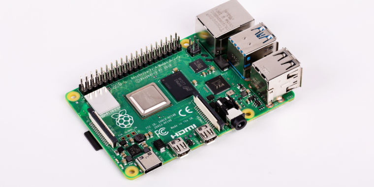
Ars Technica
Beta bootloader is available now, will roll out to all Pi 4 boards later.
ripe pike
turbid rivet
Based on ArsTechnica (https://arstechnica.com/gadgets/2022/02/raspberry-pi-bootl...
Ah perfect ty - that's the info I was looking for
glacial gale
so i just cracked the housing on this component. i hope it will be fine. it looks like its funcyional parts are all intact, just a broken housing. i think its some kind of coil
 ruby night
glacial gale
so i just cracked the housing on this component. i hope it will be fine. it look...
ruby night
glacial gale
so i just cracked the housing on this component. i hope it will be fine. it look...
seems to be a fairly common issue https://community.element14.com/products/raspberry-pi/f/forum/31207/there-is-a-broken-chip-on-my-rpi3-motherboard-labeled-4r7-i-just-bought-it-and-it-broke-while-trying-to-install-it-inside-the-case-will-the-board-still-work-with-that-chip-broken-can-i-cover-it-with-epoxy
civic rune
Having a weird issue
Sometimes my pi will lose the ability to click important buttons


This seems to happen when I plug in some I2C breakout boards that use 3.3V
I can't even open a terminal to shut down, I have to pull the power cable
 pliant pebble
What model?
civic rune
AW9523
pliant pebble
Mmm, yeah
pliant pebble
Are you sure they're 3.3v?
civic rune
yup
because the I2C bus is pulled up to VCC. If VCC were greater than 3.3V it would damage most microcontrollers
chip datasheet says that 3.3 is acceptable
pliant pebble
Did you do any soldering on the board??
pliant pebble
I'll try one on mine - I'm pretty sure I have one. I'll get back to you
civic rune
thanks!
pliant pebble
NP
civic rune
pliant pebble
I'll try one on mine - I'm pretty sure I have one. I'll get back to you
make sure you have the pi plugged in and running before you power on/connect the '9523
to replicate the issue
civic rune
running into another issue, this time with instantiating I2C using board.I2C()
I run that and I get, after a long stack trace:
ValueError: No Hardware I2C on (scl,sda) = (3,2)
Valid I2C ports: ((1,3,2),(0,1,0))
isn't that when you need to enable I2C in raspi-config ?
civic rune
I would have thought that installing blinka would do it, I swear it has in the past, but I don't recall clearly
hey that worked!
tired marsh
I believe the adafruit install script does it in theory, not pip install
civic rune
Huh
I must have used the adafruit script to do it in the past? Don't recall. Thanks for the tip
ruby night
This guide walks you through it https://learn.adafruit.com/circuitpython-on-raspberrypi-linux/installing-circuitpython-on-raspberry-pi
civic rune
thx, I have kind of a weird setup on this pi. Mr. T is trying to teach my some software and it's led us down some interesting paths
civic rune
I'm following this guide https://www.kite.com/python/answers/how-to-check-internet-connection-in-python but I get an error when I import requests
ah I guess it's just not a default lib in python
is the first library that shows up in my package manager, requests Python HTTP for Humans, the one I'm looking for?
olive haven
that's it
civic rune
cool thanks
I'm overdoing some test code because I want to learn things
hmm is there a way for my python program to tell if it was run from 1) the REPL 2)By clicking run in an IDE 3) from a command line or 4) automatically by say a process?
I want to be writing to a file, but I don't necessarily want the file to be overwritten on subsequent runs, so I was thinking a popup box that allows you to enter a new filename? I think I may be over thinking this since I'm writing test code that only I will ever run so I can just manually change the filename to be used in the code
if I want to write a text file, do I do filename = "somename.txt"?
olive haven
civic rune
I want to be writing to a file, but I don't necessarily want the file to be over...
You could make the filename a command line argument.
civic rune
I was thinking of that
olive haven
I didn't understand your next question about writing a text file. You mean as opposed to a binary file?
 obtuse ermine
Hey guys im trying to find a pinout for the raspberry pi 4 b 3.5mm av jack and I cant seem to find one anywhere. Does anyone know an easy way to tell the channel pads apart?
I want to hard solder an amp onto those pads for 2 4 ohm speakers lol
 hollow socket
put the plug in and test it with a continuity tester
 low vessel
I recently made the switch on my pi4 8gb to 64 bit rasp os and after reinstalling zsh, tmux, docker and some themes like powerlevel10k and ohmyzsh my pi idles at 1800 for the cpu frequency with dips to 600 every so often. Is that good for the pi to run at max frequency the majority of the time. At idle utilization is 3% and I’m not getting any extra heat. I have fresh installed 64 but twice now and it still does the same thing
humble marsh
obtuse ermine
Hey guys im trying to find a pinout for the raspberry pi 4 b 3.5mm av jack and I...
https://www.raspberrypi-spy.co.uk/2014/07/raspberry-pi-model-b-3-5mm-audiovideo-jack/ has the plug wiring but not the pads. https://forums.raspberrypi.com would be a good place to search, and to ask further.
doing continuity tests would be good too, as Keri says
obtuse ermine
Yeah I'll just fluke it out to make sure. I don't have an extra 3.5 plug to mess with lol
 haughty hornet
should I ask here for issues with raspberry pico and circuitpython?
lost wolf
haughty hornet
should I ask here for issues with raspberry pico and circuitpython?
Nope! Please ask in #help-with-circuitpython
You'll get better assistance!
haughty hornet
okay thanks!
 shadow prism
For those that bought fingerprint scanners for RPis, which ones are reliable in your experience?
 lost stirrup
Hey, can someone kindly explain to me how clock divider in PIO works? I want to set a clock 5Hz in 74HC595, but I couldn't 😦
civic rune
I definitely set up a username/PW on my pi, but when I turn it on, I'm not prompted for one. Is this normal behavior?
 simple flame
civic rune
I definitely set up a username/PW on my pi, but when I turn it on, I'm not promp...
simple flame
civic rune
I definitely set up a username/PW on my pi, but when I turn it on, I'm not promp...
most likely an option turned on in raspi-config
civic rune
ah thx
civic rune
what is likely to be more accurate?
- calls to pygame.mixer.music.get_pos()
- time.monotonic() - init where init is a time.monotonic() call right after the song starts
 neat flint
@civic rune If you have time.monotonic_ns() on your board I'd suggest using it instead if you need accuracy.
Unrelated, but I am sad the RPi foundation didn't take the Zero 2 W as an opportunity to use USB C.
civic rune
neat flint
<@!887510739462537236> If you have `time.monotonic_ns()` on your board I'd sugg...
I don't need super duper accuracy, a few ms off is fine, I was just curious for when I do need accuracy
hardy plaza
You won’t get guaranteed accuracy both due to Python and due to Linux on the Pi since Python is getting time-shared and is affected by system load
If you want accuracy you probably should move to an MCU
And note that RTCs are accurate over days and weeks but not at the micro or millisecond level
civic rune
Oops, thought I was in robotics
It's not over a long period of time. I expect the drift in the clock to be <1ms
hardy plaza
Then you can’t do that on a Pi
civic rune
Can't do time.monotonic()?
hmmm
I can be off by a few ms and it doesn't matter
but the code I'm profiling must be run on a pi
hardy plaza
civic rune
hmmm
Oh, you'll get a value but it won't be accurate at millisecond accuracy. I'd suggest simply trying things out and noting that the values returned by any time function on Linux on a Pi won't be accurate at high resolution. RTCs over longer periods can have seconds per month, etc. but the code that delivers your function is sharing the OS and there's no backing clock except for the system clock.
That said, it may very well be accurate enough for your (and most people's) purposes.
I ended up hooking an MCU to my Pi to use as a reference clock since my Pi gets under heavy load at times.
civic rune
Yeah I can be like 30 ms off and it won't make an appreciable difference
hardy plaza
Then you're probably fine. I am using mine for a PID controller where each call must be quite accurate otherwise it can get into bad feedback loops. Actually, four PID controllers.
hardy plaza
rotund pivot
<https://docs.python.org/3/library/time.html#time.perf_counter> can be handy
Yes, but no more immune to clock fluctuations than any Python time function. If one's requirement is milli- or microsecond accuracy in Python on Linux, you need to provide a hardware clock that isn't affected by load or time-sharing.
Basically what I'm saying is that you need a hardware clock with the required performance, not a software clock.
rotund pivot
yes, though a larger sample size can help
an alternative could be triggering something off-board that can measure more accurately
hardy plaza
rotund pivot
yes, though a larger sample size can help
Over multiple calls, yes, but if we call "resolution" the ability for a single call to be accurate at the micro- or millisecond level, it must be a hardware clock. As to an external clock, I mentioned that I'm myself using the hardware clock of an external MCU connected to my Pi as my source of a 20ms pulse. I'm getting accuracy (resolution) there of about 1-2%. And any MCU will do, clearly the higher clock speed the better. I'm using both a TinyPICO and a QT Py RP2040 for this.
If I try to get a 20ms pulse from the Pi itself (in Python) that clock can vary from 20ms to 40ms or more etc. depending on load.
rotund pivot
Makes sense. I only expect my Pi(s) to be fast, not precise.
civic rune
If you want true precision, Python is also not the best bet
rotund pivot
I've seen SAMDs drift up to a second per minute 😦 Espressif are much tighter. Haven't measured RP2040.
hardy plaza
I’m not sure how much of a market there’d be but I’d love it if Adafruit or Pimoroni or somebody would sell a high resolution microsecond accurate I2C clock board. Nobody does AFAIK 😔
It wouldn’t even need to be setable really or even provide milliseconds since the epoch like in Java, but that’d be handy
Even just a relative 1uS pulse would be welcome
umbral sable
hardy plaza
I’m not sure how much of a market there’d be but I’d love it if Adafruit or Pimo...
Would you want like a pulse-per-second output for the high resolution? I2C isn't fast enough to do microseconds itself.
hardy plaza
Any coms on Python on Linux is prone to that issue, but if I called the board I’d always get a 1uS accurate number (absolute or relative) subject to the constraints of the cons protocol. I’m not sure how else it could be connected to the Pi...
s;cons;coms
umbral sable
GPS does it with a separate PPS output signal, where the edge is exactly on a second boundary, even though the UART stream is much slower.
hardy plaza
Yeah, like an RTC GOS is very accurate over longer periods but low resolution
I hate typing in a phone 😑
s;GOS;GPS of course 😑
(I’m lying in my hammock in my front porch so I really shouldn’t complain) ☺️
 warm remnant
what is the ground symbol on the back of the rasberry pi mean exactly? cant find it anywhere

well i assume its ground
civic rune
I wouldn't necessarily assume that
warm remnant
i should mention i dont expect it to to be your typical ground if anything tho
 wraith grove
Eddy, the E that eats capacitors!
civic rune
warm remnant
i should mention i dont expect it to to be your typical ground if anything tho
I don't think there's more than 1 ground on the pi
Maybe isolate the image and do an image search?
umbral sable
Seems to be a TELEC certification symbol, which is the Japanese equivalent of the FCC. https://www.gmcompliance.com/japan-telec-certification-service/
Japan TELEC Certification Service
civic rune
I thought some regulatory body
 mossy verge
Anybody have experience in Plymouth theme creation? I've been fiddling with it for days now, and am at the point where I am just ready to pay someone to convert a MP4 into a usable Plymouth theme >< I found some OSS software to do it, but spent a day on EOL'd Python2 libraries before giving up.
 tidal lance
This may have been asked before, but could I use the Raspberry Pi 400 and use the CYBERDECK HAT and a screen as the main screen output instead of a connected HDMI?
steady rose
yes
other than the STEMMA connectors, it's really just a GPIO adapter - not much going on
so can just follow same TFT guides that show how to set that up
product page list various TFTs:
https://www.adafruit.com/product/4863
so just follow those, and then to their learn guides, and follow that
other than this one potential quirk:
https://learn.adafruit.com/cyberdeck-bonnet-and-hat/fixing-pin-conflicts
there's nothing CYBERDECK specific to deal with
tidal lance
Awesome, thank you!!!
thin wagon
Can I somehow debug a .net f program running on armv6 ( pi zero , mono )?
Im having an issue thats arm specific as it works perfectly on my windows machine.
hardy plaza
thin wagon
Can I somehow debug a .net f program running on armv6 ( pi zero , mono )?
Im hav...
QEMU may be the tool you're looking for: https://www.qemu.org/docs/master/system/target-arm.html
Though perhaps I'm a bit confused about what you're trying to accomplish, so here's another angle:
https://developer.arm.com/tools-and-software/server-and-hpc/compile/arm-instruction-emulator
Arm Developer
Arm Instruction Emulator allows you to run Scalable Vector Extension (SVE) code on Armv8-A compatible platforms
thin wagon
hardy plaza
QEMU may be the tool you're looking for: https://www.qemu.org/docs/master/system...
Yeah, no I need to be able to debug c# (.net framework) code running on pi zero w, if accomplishable by any means?
zealous seal
thin wagon
Yeah, no I need to be able to debug c# (.net framework) code running on pi zero ...

Learn how to debug .NET apps on Raspberry Pi and similar devices.
thin wagon
zealous seal
https://docs.microsoft.com/en-us/dotnet/iot/debugging?tabs=self-contained&pivots...
This is with .NET core though (speculating since console has a command dotnet publish) ?
Pi zero doesnt support it since its arm6
zealous seal
Not sure - I haven't tried it. If it is possible - something like this is probably the way.
thin wagon
Yeah with .NET core, my program is running on .netframework aka mono on linux
zealous seal
hrmmm, it does say you can choose .net or .net core. Its probably worth a try with .net. If you're using the visual studio instructions I don't think you even need to install anything on the pi
thin wagon
I'm using rider on my main pc :/
Doesnt vs code require like 30 extensions to work with c#
zealous seal
Yeah, it also runs directly on the pi (its so slow on an original zero and 3 b+ or less though). I don't think you need any extensions if you use the free full Visual Studio - but thats its own hassle.
Doesn't seem to be a lot of literature about debugging it with other things. Worst case - you could just fall back to logging
 solemn briar
Anyone have a favorite USB webcam? Decent resolution… and extremely “plug and play” friendly? Ideally NOT requiring a USB power hub.. this will be on a RP400
lost stirrup
Hello, does anyone have experiences with PIO RP2040? I have read its datasheet and it shown there about period of cycle (page 332), I am wondering why this .program squarewave has 4 cycles instead 5? Does [1] not count as a cylce? Or am I missing something? Thank you!
c .program squarewave set pindirs, 1 ; Set pin to output again: set pins, 1 [1] ; Drive pin high and then delay for one cycle set pins, 0 ; Drive pin low jmp again ; Set PC to label again
umbral sable
I'm not that familiar with the PIO, but I'd assume that the cycles would be:1: drive pin high 2: extra delay on that command 3: drive pin low 4: jump statementSo it ends up with 2 cycles high and 2 cycles low.
lost stirrup
Yes I think the same way too, this [1] wont count as 1 cycle, but I need like a theoretical reason behind it 😅 thank you for the answer!
scarlet latch
Hey guys i purchased the smartPI touch pro from adafruit. I have to say this is a wonderful addition. Excellent instructions. Very happy with this!
I did have a question. I installed an onscreen keyboard thats pinned to the task bar. Very nice. But running scripts in a cmd window I cant seem to use ctrl d to terminate them. Any suggestions? Mostly looking to end and restart a script after sending changes from my pc
faint sparrow
You can probably trap a Control+D.
Your terminal would be configured to pass it to the far end of the connection (may not want to by default).
I don't know what a 'cmd window' would be in this context.
In unix maybe stty could help.
I use it to catch one signal that gets passed through if I do not do it.
 $ stty -isig
 $ ssh -p 987 this.host.com
[-]isig
  enable interrupt, quit, and suspend special characters
I was keyboard-flubbing which disconnected me from their server, and the above helped that.
(in a live keyboard telnet-like session)
humble marsh
solemn briar
Anyone have a favorite USB webcam? Decent resolution… and extremely “plug and p...
I have a couple of Logitech C920's. There are several other models in this series. They work fine on Linux and Windows. They have a standard interface. They were scarce for a long time but are now generally available again.
civic rune
I'm looking for the "best" way to upgrade python on my Pi to the latest version. This (https://stackoverflow.com/questions/64718274/how-to-update-python-in-raspberry-pi) accepted answer has an intermediate step where you run sudo apt-get install -y build-essential tk-dev libncurses5-dev libncursesw5-dev libreadline6-dev libdb5.3-dev libgdbm-dev libsqlite3-dev libssl-dev libbz2-dev libexpat1-dev liblzma-dev zlib1g-dev libffi-dev
and claims it makes managing dependencies much easier. I don't like running random code that I don't understand. Does anyone know off the top of their head what all these installs are?
faint sparrow
I'd be all about sudo apt-get -d install <foo> and then drop the -d switch on a repeat iteration.
precede with sudo apt-get update
You can also sudo apt-get upgrade which iirc is fairly global.
There's a dist-upgrade (or similar spelling) target as well.
civic rune
I just did the sudo apt-get update and sudo apt-get upgrade and dist-upgrade on thursday
faint sparrow
Then it ought to be current I'd suggest.
When you do try to upgrade python it'll most likely tell you you already are on the lastest version.
civic rune
I have 3.9, latest is 3.10
faint sparrow
I don't remember if apt-get requires you to solve dependencies by yourself (it might!)
You can look at package files to check on that.
civic rune
I probably don't need 3.10 but all the docs for the libraries I want to use are in 3.10
ooooh
I can change the version
faint sparrow
/var/lib/apt/lists has the resources.
civic rune
thx
 grand sparrow
hello, can someone please tell me how to write a nodejs script to ping each second my bmp280 sensor that I hooked up to my raspberry pi?
I connected like this https://i.imgur.com/KtIUzb3.jpg
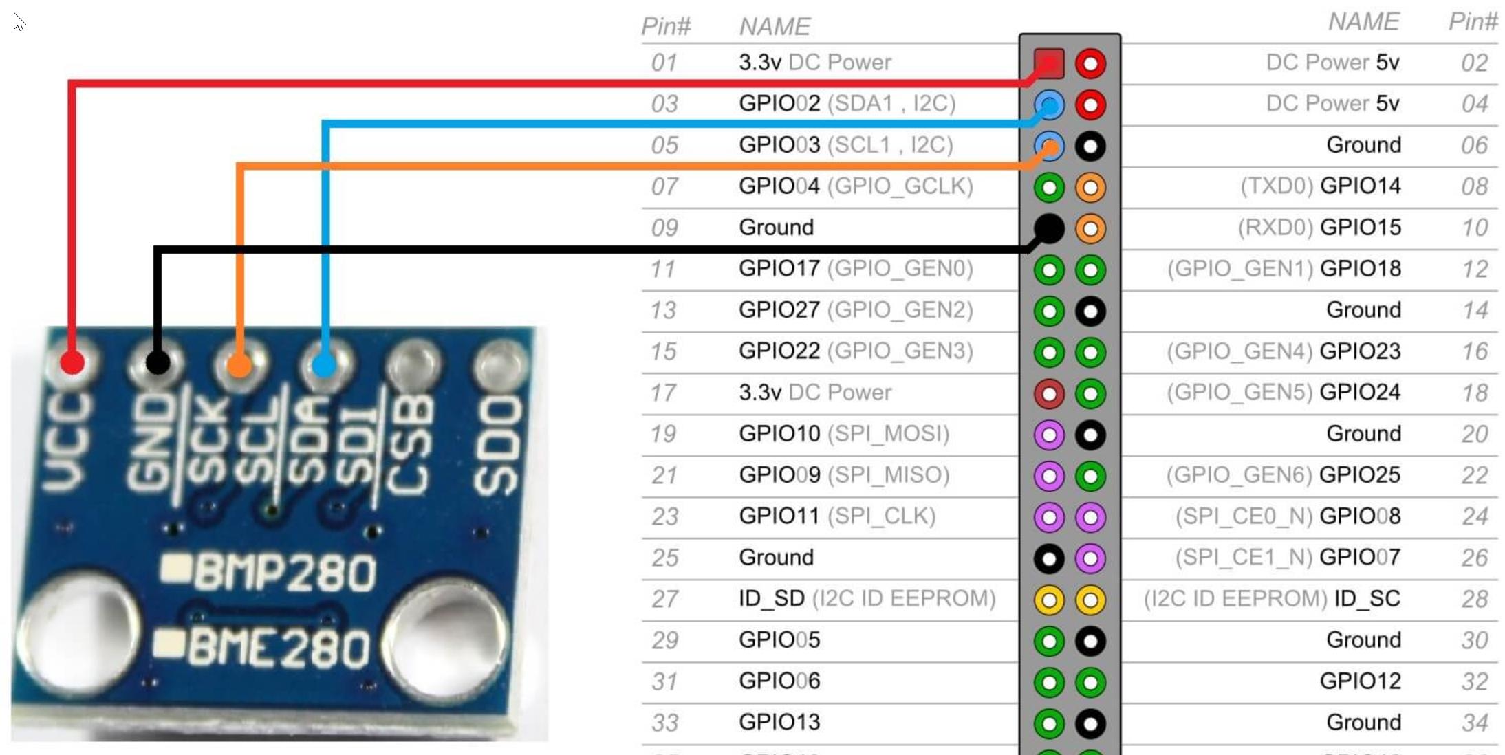
 faint sparrow
@civic rune for regular Debian I usually:
https://packages.debian.org/bullseye/python3
civic rune
what would be a good tool to create a CSV manually on a pi?
civic rune
faint sparrow
<@!887510739462537236> for regular Debian I usually:
*<https://packages.debian.o...
cool thx
faint sparrow
here's debian's 3.10 version:
if it says 'pool' in the path you're in the right place (for Debian).
I have downloaded directly from these directories and installed the .deb manually, and resolved dependencies myself.
Can be a project. ;)
civic rune
I don't actually need any features in 3.10, I just mistakenly thought I couldn't access the 3.9 docs
humble marsh
civic rune
what would be a good tool to create a CSV manually on a pi?
print statements, or a spreadsheet program like LibreOffice Calc"
civic rune
ooh ok thanks
I'll see how to install that from the command line, it's a 3 A+ so it struggles to do much of any web browsing
humble marsh
you mean Google Sheets is difficult, I guess
civic rune
I can't tell if libreoffice actually installed or not, at the very end of the process a fetch failed, and I can't find Libre Office anywhere in my pi.
The error message is too long to type out and too long to take a picture
civic rune
Every time I think "I'll just do some simple web browsing on my pi, can't hurt right?", I get burned. Every time.
grand sparrow
hello can someone please can help me regarding bmp280 sensor
when I run i2cdetect -y 1 it shows me an address i2c on 76
and then I put this code, but it doesnt work:
const bme280 = require('bme280');

bme280.open({i2cAddress: 0x76}).then(async sensor => {
  console.log(await sensor.read());
  await sensor.close();
}).catch(console.log);
this is nodejs script
inland mango
Any suggestions for setting up Rhasspy on a Pi 4 / Voice Bonnet pair ?
Running Raspi Lite (32bit).. The bonnet works..
 queen gull
I have a question about RPI and neopixels. So it's about the brightness. I mean to me there is a good variation of the brightness from 1 to 2 but to me 128 to 255 they all look the same. Is it normal I am missing something. Thanks!!!
faint sparrow
;)
You can measure the total current in the strip.
Maybe use a 'lux' meter.
candlepowerforums is the place where they ask how bright a light is
umbral sable
queen gull
I have a question about RPI and neopixels. So it's about the brightness. I mean ...
That's quite normal. The PWM value controls the linear amount of current and light, but the human eye perceives "brightness" very non-linearly, since we have to go from moonlight to sunlight across many orders of magnitude.
queen gull
Ok so I'll try to work around the issue then in code. Thanks there are no 10 bits strip for 1024 variation ? 😉
umbral sable
Not in the smart-LED world that I know of. There are some standalone LED controllers with 16-bit PWM on top some analog current control, though.
zealous seal
queen gull
Ok so I'll try to work around the issue then in code. Thanks there are no 10 bit...
You can probably apply a logarithmic curve to your adjustment parameter to make it feel linear
umbral sable
"Gamma correction" is a good term to research for that.
civic rune
Anyone have a good text editor for the pi that isn't Nano? I am looking into Sublime Text to see if it will run OK on my machine
steady rose
for what main purpose? quick and easy edits of a text file? or code editting with syntax highlighting, etc.?
civic rune
I'd like to be able to some coding with it yeah
steady rose
check out vs code also:
https://code.visualstudio.com/docs/setup/raspberry-pi
civic rune
ah well, sublime text doesn't work on my pi it turns out
thanks I'll check that out
Shoot, it runs real slow, it seems it's not officially supported. I'll see about other options. I need the absolute basics when it comes to syntax highlighting
steady rose
did you try geany? i think that's preinstalled maybe?
civic rune
Geany seems OK, I was just hoping to duplicate a workflow on my normal PC. It's not a big deal
civic rune
yup
Notepad++ is not super fancy, but doesn't seem to exist for linux at all
and if I don't have the absolute weakest pi available, it's close
 slate pulsar
Hi, i have been watching at this hat: https://shop.pimoroni.com/products/adafruit-1-3-color-tft-bonnet-for-raspberry-pi-240x240-tft-joystick-add-on. and I was wandering, could use it with retropie on a raspberry pi zero?
turbid rivet
slate pulsar
Hi, i have been watching at this hat: https://shop.pimoroni.com/products/adafrui...
Yes to Pi zero. Retropie doesn't recommend it, but I believe there are ways to make it work?
 slate pulsar
so If I install the driver it should display raspbian or retropie?
turbid rivet
Not sure. I think people have had to use some pretty hacky workarounds to get it to display any kind of desktop.
slate pulsar
do you recommend any hat to create a handheld emulator?
 tawdry sigil
Hey y'all got a beginner question here. So I am powering my raspberry pi zero w 2 via the gpio pins. I have a simple switch that allows me to turn on and off the pi. This switch is rated at 3A DC but I can't seem to be able to power the pi with it. Powering the pi works fine when it doesn't run through the switch. Any idea on what I could do here? This is my circuit:
 civic rune
do you have a DMM?
tawdry sigil
yeah it never goes over 1A though when it isn't using the switch
civic rune
I was going to suggest testing continuity between the pins you're trying to pass power through, while the in the position you intend to be the "on" position.
I'm not sure about the pi zero but note that for the other pis, suddenly cutting power to it is usually advised against
I'm following the instructions here https://www.geany.org/download/themes/ but I don't see a directory ~/.config
Geany ThemesGeany-Themes is a collection of color schemes for Geany, either written originally by the Geany community or ported from color schemes for other editors.These schemes are compatible with Geany 1.22 and greater.
ah there it is
tawdry sigil
yep I have continuity
faint sparrow
~/.config/geany/filedefs/filetypes.common
Try geany with and without that file present.
civic rune
I might be crazy, but I think that the password I set up for my pi at first boot just straight up didn't stick....
Is that possible?
Unrelated, but I'm getting connection refused when I try to ssh into my pi from my windows machine:
C:\Users\MyName> ssh pi@MyPiIPAddress
figured out I should be using wlan0 and no lo, but now I get connection timed out
civic rune
I opened a file with Nano and then somehow closed it without closing it. Now when try to open it again I get
File TheFile is being edited by root open anyways?
How can I fix this?
umbral sable
Chances are the previous instance of Nano is still running in the background somewhere. You could try to re-foreground it, or kill the process.
civic rune
what does fore-grounding it look like?
or killing it for that matter
or rather how do I find a pid?
tired marsh
look in top or ps
civic rune
hmm
shadow prism
Situation: I bought a USB dongle that allows me to power the Raspberry Pi Zero over a USB-A port. Here: https://www.amazon.com/iUniker-Expansion-Breakout-Raspberry-Inserted/dp/B07NKNBZYG/ref=sr_1_6?keywords=raspberry+pi+zero+2+w+usb+dongle&qid=1643130449&sprefix=raspberry+pi+zero+2+w+usb%2Caps%2C83&sr=8-6
I followed the instructions to set up SSH via USB, yet I cannot get access on SSH on neither Linux nor Windows.

iUniker USB Dongle Expansion Breakout Module Kit for Raspberry Pi Zero/W, Both Front & Back Side Can Be Inserted
tired marsh
I usually use ps aux | grep something
civic rune
hmmmm kill Operation not permitted
tired marsh
sudo it, it's a root process
tired marsh
might be some lock file ?
civic rune
I'll try closing the command window and re opening
that did it lol
well I learned something
tired marsh
oh well, close window(s) and open it back up fixed it again 😄
civic rune
turn it off and on again! always
civic rune
Has anyone used the RPI Imager and noticed that it doesn't actually set a password?
olive haven
Which version of Imager are you using?
civic rune
the absolute latest AFAIK
ah it sayts 1.7 but I updated to 1.9. Let me try again
nevermind, 1.7.1 is the latest, I was thinking of some other software
Yup, just re-tried it and it simply didn't work
Also the password setup procedure doesn't actually make a password stick. When I go to raspi-config and click Change Password it simply prompts me to enter a new password, and doesn't require the password I just set first
olive haven
which image did you set up?
civic rune
the default basic one at the top
olive haven
I'm trying it now; I'll let you know how it turns out.
civic rune
Cool, thanks!
olive haven
(I've had this work before, with a previous Imager)