#help-with-linux-sbcs
1 messages · Page 7 of 1
 rotund pivot
 waxen bane
header and jumper
rotund pivot
ok
can you post the current code, and describe the behavior when it runs?
exceptions, serial print output, etc
waxen bane
from time import sleep

servo = AngularServo(2, min_pulse_width=0.0006, max_pulse_width=0.0023)

while (True):
    servo.angle = 90
    sleep(2)
    servo.angle = 0
    sleep(2)
    servo.angle = -90
sleep(2)```and no movement from the servo at all
rotund pivot
now you're onto a 3rd GPIO library :p
waxen bane
smh idk what im doing
i just saw that was the one to use for hooking up right to the pi
unfortunetly i have to head to bed for work tomorrow 😦 im going to try some more trouble shooting after work
thanks for all the help @rotund pivot
rotund pivot
if you think some pins are fried, that can be tested with little code next time you're working on it
 muted ether
for anyone trying to get blinka running on raspberry pi os bookworm, they swiched how python works. https://www.raspberrypi.com/documentation/computers/os.html#python-on-raspberry-pi I had to create an environment running "python -m venv .pi --system-site-packages", then download rapi-blinka.py and comment out the shell.bail line on line 48. Next run "sudo bash" since the raspi-blinka.py has to be run as root. Then run "source .pi/bin/activate" and run "python3 raspi-blinka.py"
another thing to note, if you are running a little display as a service (for system stats or something), I had to change how that was done. Rather than running it through /usr/bin/python3, it looks like this now:
[Unit]
Description=OLED Display
After=multi-user.target
[Service]
Type=idle
ExecStart=/home/pi/.pi/bin/python3 /home/pi/piprojects/waveshare_base_b/oled_display_service/display_stats_adafruit_ssd1306.py
Restart=on-abort
[Install]
WantedBy=multi-user.target
 zenith crystal
lovely (used both sarcastically and for the workaround) 😈
 vocal lava
I guess it was an upstream Debian decision - the only way to install something via pip is to do it in a virtual environment
 tiny fable
https://peps.python.org/pep-0668/ is where it was implemented
Python Enhancement Proposals (PEPs)
The only PEP I have memorized 
 dusk flower
Does anybody know whether OPi5+'s GPIO is the same as RPi's one?
 broken shuttle
Different chip, so it won't be identical. That being said SBC vendors will usually try to line up as best they can.
dusk flower
Ye, found their datasheet.
Pwr pins are the same, so are the gpio, only their alt confs differ in some pins
broken shuttle
Yeah, so the question is whether the HAT you are going to use supports the right alt functions.
dusk flower
No plan on doing so anyway
 velvet rampart
dusk flower
Does anybody know whether OPi5+'s GPIO is the same as RPi's one?
velvet rampart
dusk flower
Does anybody know whether OPi5+'s GPIO is the same as RPi's one?
u probably have to use the classic bank, chip, and pin formula also... if it's anything like a radxa board. i couldn't get my fav pip libraries to play nice with rock5a
it would be something like gpiod you would be using, let me show you a sample of what worked
`# import gpiod
import time
import Adafruit_GPIO.SPI as SPI
import Adafruit_MCP3008
import uinput
SPI_PORT = 0
SPI_DEVICE = 0
mcp = Adafruit_MCP3008.MCP3008(spi=SPI.SpiDev(SPI_PORT, SPI_DEVICE))
left_stick_x = 0
left_stick_y = 1
chip = gpiod.chip(4)
# 32 x GPIO"X" + 8 * GPIO_"BANK" + GPIOX_BANK"LINE" = PIN
# pinCalc = 32 * GPIO_LABEL + 8 * CHIP + LINE
pin = chip.get_line(0)
config = gpiod.line_request()
config.consumer = "Line"
config.request_type = gpiod.line_request.DIRECTION_INPUT
pin.request(config)
while True:
# print(pin.get_value())
print(mcp.read_adc(left_stick_x))
time.sleep(0.02)`
depending on what u are trying to do you would need various overlays such as a the spi overlay, like if you're using armbian it would be armbian_add_overlay etc. it's quite verbose in order to utilise gpio with rock and i imagine rock is similar
but they do work ^^
 faint sparrow
how can I see what this build has installed, and how do I get the nano editor? all commands that I know and random google suggestions seems to not be installed/known by buildroot
 zenith crystal
you don't have "normal" OS options here, apparenlly -- this is a very constrained sandbox; according to the README try make menuconfig?
velvet rampart
faint sparrow
how can I see what this build has installed, and how do I get the nano editor? a...
Looks like you'd need to install apt first
faint sparrow
zenith crystal
you don't have "normal" OS options here, apparenlly -- this is a very constraine...
 faint sparrow
velvet rampart
Looks like you'd need to install apt first
faint sparrow
velvet rampart
Looks like you'd need to install apt first
indeed, the problem is how? I have no idea what this thing has or hasnt
to sum up I wanted to change the interface from a dhcp to a static ip, but within the console I cant open the file, while on stuff like mobaxtime, it saves the file, but it doesnt look like its actually applied to the machine, since the ip its the same
velvet rampart
Is this because your printer IP is changing dynamically and you want to set it to not change? I'd say why not just lock it on your router side that way your router will follow instead of messing around there
To install apt is a few steps, there are guides out there
But who knows what will work if you are on some sort of creality Linux
faint sparrow
velvet rampart
Is this because your printer IP is changing dynamically and you want to set it t...
I am using my smartphone hotspot as wifi (mobile offers here are better than domestic); anyhow it has opkg, thanks
zenith crystal
the README for buildroot indicates that it's a reduced OS for cross-compilation, so that makes me wonder what in the world you're doing with IP addresses... 😕
oh ... "crealty" from stej was the clue: second the motion on just supplying a non-changing DHCP supplied IP from the router
dusk flower
velvet rampart
u probably have to use the classic bank, chip, and pin formula also... if it's a...
They seem to have released their own implementation of WiringPi, if it helps
velvet rampart
i ended up using gpiod. it worked fine with a helper function but ultimately gave up on that board. was too messy for my beginner skills
 lucid nebula
Did XRDP get an update? I can't remote into my pi anymore
 wind heron
hi, did anyone follow the "1.3" 240x240 Kernel Module Install" tutorial lately? you cannot use python3 to install stuff anymore (the famous "This environment is externally managed") and the script fails, so I do not know how to carry on to get the module installed...
I have tried with pipx and a virtual environment (venv), but it failed anyways
 steady rose
there will be lots of things that will break due to changes in bookworm
it will take some time for the guides to get updated
wind heron
do you have any experience about how long i.e. if they get updated within a couple of weeks after a new version of the OS arises? I just bought the Adafruit Mini PiTFT and if I should expect no update until next year or so, then I could return it now before it is no longer possible
steady rose
easiest near term solution is to probably use the pi os release prior to bookworm
this is what you're currently attempting?
https://learn.adafruit.com/adafruit-mini-pitft-135x240-color-tft-add-on-for-raspberry-pi/1-3-240x240-kernel-module-install
wind heron
yes, exactly
steady rose
wind heron
it seems that someone is already working on that, good news! thanks
steady rose
can keep an eye on that issue thread for progress
muted ether
I created a note for anyone trying to get the Google Coral USB Accelerator working on Raspberry Pi OS Bookworm. https://adafruit-playground.com/u/bdsvac/pages/google-coral-usb-accelerator-on-raspberry-pi-bookworm
 bright glen
Alright i'm hoping this is ths best chat to help me with my current issue, if not, then which one of the help ones would be. I have been trying to get my i2c pi oled hat to work on a raspberry pi 4 and have been unsuccesful. I have utilized the walkthrus on the adafruit site, as well as reading within the raspberrypi documenation about pip and venv.
I removed all the configuration as best I knew how, then added another venv, installing adafruit within the venv, pip, pillow, etc. Ran the raspi-blinka.py. I attempted to # out line 48 as I saw somewhere else within discord that can an issue /shrug
When I run $ python blinktest.py
Hello blinka!
Digital IO ok!
I2C ok!
SPI ok!
done!
when I run the pyhton3 stats.py it times out. I clear it and run again with -v and it's stopping at this point
import 'microcontroller.pin' # <_frozen_importlib_external.SourceFileLoader object at 0x7fa2b3ea90>
import 'microcontroller' # <_frozen_importlib_external.SourceFileLoader object at 0x7fa2b32010>
this is all i'm getting on my display

 woeful wigeon
Hi, I want to ask, is it possible for the raspberry pi to update itself using a .img file on a USB flash drive ? So like let's say my Raspberry pi is up and Running using the Raspberry pi Buster OS (desktop version), is it possible for the raspberry pi to update itself whenever the USB flash drive is detected and there's a .img file inside the Flash drive?
ChatGPT gave me this answer but i'm not confident that this is gonna work

 rancid kindle
woeful wigeon
Hi, I want to ask, is it possible for the raspberry pi to update itself using a ...
rancid kindle
woeful wigeon
Hi, I want to ask, is it possible for the raspberry pi to update itself using a ...
Definitely do not follow those instructions. They'll overwrite the contents of the Pi's SD card with the contents of the image file and you'll lose whatever you have there.
Why do you want to update it this way rather than using a live network connection?
woeful wigeon
rancid kindle
Definitely do *not* follow those instructions. They'll overwrite the contents of...
Okay so i have developed a system on raspberry pi and i want to deploy it in the field But in the field there will be no Internet connection ever so my software can't get over the Air updates and i can't be there in the field so i need a method of updating the software on the raspberry pi using a USB flash drive that i can handle over to a person Who can just plug the USB into the pi and pi update itself,
i can just overwrite my software Files using a simple script that copies the code from the USB flash drive to the internal storage of raspberry pi but what if in future there's some OS configuration i have to do in future to run my future software versions. So ideal method of update would be then to just flash the Raspberry pi SD card with the Custom OS image.
the raspberry pi is fitted inside an enclosure so there's no easy access to the SDcard, There's only 1 USB port of Raspberry pi Sticking out of the enclosure So... i need to do it over USB
broken shuttle
I think your first problem here is going to be that whatever SD card gets put in will die eventually.
rancid kindle
woeful wigeon
Okay so i have developed a system on raspberry pi and i want to deploy it in the...
That makes sense.
You might look at apt-offline. It can download files necessary to do an offline update on one system and then perform the offline update on another.
@broken shuttle's comment about SD cards is spot on, too. SD cards are not really very durable and aren't really designed for the kind of use they see in Raspberry Pi's. A good card might last a long time but it's really a gamble. Whatever you do if you're running off SD cards you'll need to be able to handle them failing.
apt-offline is an offline package management tool that is used to install/upgrade software packages with their dependencies on Debian-based Linux distributions.
woeful wigeon
rancid kindle
That makes sense.
You might look at [apt-offline](https://www.ubuntumint.com/ap...
Thank you for the suggestions, i'll see what i can do, There must be a good way of doing it
zenith crystal
since this seems like you're not necessarily interested in keeping what's on disk, you could also just burn new SD cards for updates -- if there is any information that needs to be copied over, it could be done on a field laptop with an SD card reader and appropriate app/script (remove old card, insert into laptop, copy data, remove SD, insert new SD, copy data, remove from laptop and put into pi
you could also make a new image based on what's on the laptop since it sounds like you've got a manual component in here as well -- e.g. do the data copy thing as above, but instead of a pre-burned image, burn the new image then insert whatever data you need copied back over
bright glen
steady rose
see if it shows up in an i2c scan
Yes I checked this it shows 3C on on this like in this example
https://learn.adafruit.com/adafruit-pioled-128x32-mini-oled-for-raspberry-pi/usage

Adafruit Learning System
The most compact lil' display for a Raspberry Pi
 ivory heart
Hello, I'm currently adding leds to my 3d printers and housings using relays to turn them on/off.
I have an issue that is probably childsplay for most here.
I can run a script that turns it on and one that turns it off. But idk how to check the state so I can have one single script that either turns it on or off, depending on the state.
This works to switch the relay and turn the lights on:
`#!/usr/bin/env python3
import board
import digitalio
import time
from os import geteuid
led = digitalio.DigitalInOut(board.PA6)
led.direction = digitalio.Direction.OUTPUT
led.value = True`
Can anyone help me with a script that switches the light, if it's on turn it off, if it's off turn it on?
wind heron
the bug fix for the adafruit-pitft.sh script did not solve the issue, at least for the miniPiTFT 1.3". I posted on the issue thread, but I paste it here for the records in case no one follows a closed issue:
it still does not work for the miniPiTFT 1.3". I followed the "Easy Install" tutorial and I started the script as described:
sudo -E env PATH=$PATH python3 adafruit-pitft.py --display=st7789_240x240 --rotation=0 --install-type=console
The script runs and I see the following at the end:
PITFT fb_st7789v.ko: 3,916 B / 16.0 KiB = 0.239 <------------ "PITFT" text is red instead of green
PITFT Updating /boot/config.txt...
Already have adafruit-pitft-helper section in /boot/config.txt.
Removing old section..
PITFT Updating console to PiTFT...
Remove fbcp from /etc/rc.local, if it's there...
PITFT Failed to disable unit: Unit file fbcp.service does not exist. <------- "PITFT" is red again
Configuring boot/config.txt for default HDMI
Set up main console turn on
/boot/cmdline.txt already updated
Turning off console blanking
Setting raspi-config to boot to console w/o login...
PITFT Success!
Settings take effect on next boot.
REBOOT NOW? [Y/n]
After rebooting there is nothing on the miniPiTFT, just the backlight on like before.
zenith crystal
ivory heart
Can anyone help me with a script that switches the light, if it's on turn it off...
please don't multi-post - a single post in a channel is usually sufficient: if there's a "better" channel, you will likely be directed there
zenith crystal
wind heron
the bug fix for the adafruit-pitft.sh script did not solve the issue, at least f...
please see the #welcome channel for directions on how to post code/terminal output -- thanks!
woeful wigeon
zenith crystal
since this seems like you're not **necessarily** interested in keeping what's on...
thanks for your suggestion but it looks like you missed one part of my message which was "the raspberry pi is fitted inside an enclosure so there's no easy access to the SDcard, There's only 1 USB port of Raspberry pi Sticking out of the enclosure So... i need to do it over USB"
zenith crystal
DOH!
i have an idea to make up for my lame one -- the LibreElec project has a way of downloading new images and updating itself: perhaps a similar mechanism might fit your needs
woeful wigeon
is it possible to disable this Pop up ?

in raspberry pi OS (Desktop)
nevermind, Found the solution
was very easy
 dusk grotto
woeful wigeon
is it possible to disable this Pop up ?
dusk grotto
woeful wigeon
is it possible to disable this Pop up ?
May I ask why you would want to remove it?
woeful wigeon
dusk grotto
May I ask why you would want to remove it?
Umm, it's complicated, basically coding a script to auto update the Software on raspberry pi whenever the USB flash drive is inserted
 stoic dawn
So should I use Bullseye for Blinka until everything is sorted out?
zenith crystal
i've got Bookworm running and just re-installed all the blinka stuff via virtual env and it all worked, so not necessarily? i didn't have any of the permissions issues others have reported, so I'm not entirely sure what's different on my systems
zenith crystal
stoic dawn
zenith crystal
i've got Bookworm running and just re-installed all the `blinka` stuff via virtu...
yeah I got it working.
 wheat reef
Hi all, I'm using an ILI9341 TFT screen on a Jetson Orin Nano connected via SPI. I was hoping to create an interface on the screen using KTinker or PyGame but I'm not sure how to direct output of these libraries to the screen. On Raspberry PI I've seen people creating framebuffers for the screen and directing output there, but I'm running Ubuntu on a Jetson and haven't encountered any drivers that allow me to do this.
What I am doing currently and trying to avoid is updating the UI by redrawing an image with shapes drawn on using pillow, as this is pretty slow and unresponsive. Am I limited to uploading images via the CircuitPython library? Does anyone know the best practice for building responsive interfaces with these screens on the Jetson?
 lean kiln
Okay, stifle the laughter, but I've got a new Pi5 and no official fan/heatsink, can I just run it with passive cooling or even no heatsinks? Assuming it would throttle but that's okay (fan on order)
 hard pike
lean kiln
Okay, stifle the laughter, but I've got a new Pi5 and no official fan/heatsink, ...
hard pike
lean kiln
Okay, stifle the laughter, but I've got a new Pi5 and no official fan/heatsink, ...
You might be okay for less intensive applications like running headless
zenith crystal
lean kiln
Okay, stifle the laughter, but I've got a new Pi5 and no official fan/heatsink, ...
you can keep track of the CPU temperature with vcgencmd measure_temp
rancid kindle
lean kiln
Okay, stifle the laughter, but I've got a new Pi5 and no official fan/heatsink, ...
This just prompted me to go check my preorder and be relieved that I ordered the cases with fans. Not gonna laugh at you, I'm sure a lot of people will be caught short by the need for active cooling.
zenith crystal
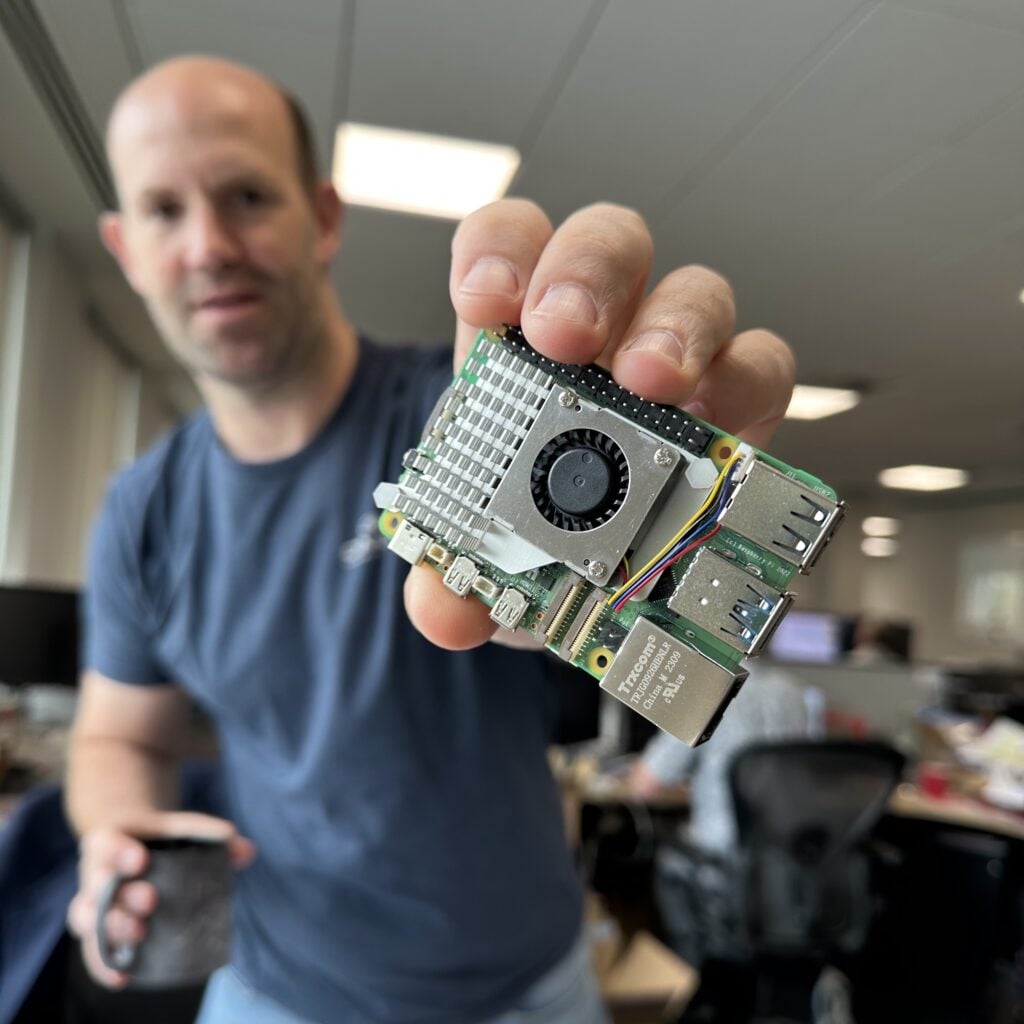
With the release of Raspberry Pi 5, we're introducing two new official hardware solutions for cooling.
 ripe pike
Here's a tricky one:
I'm using a RPi 3A+ with bookworm to set up a hotspot using the command
nmcli device wifi hotspot ssid ... password ...
I can connect another nearby RPi 4 (also bookworm) to it.
But when I try a RPi Zero W, it just won't connect. I popped out the SD card, and placed it into a RPi Zero 2 W, and it works. All the RPis are next to each other.
What's up with RPi Zero W?
broken shuttle
ripe pike
Here's a tricky one:
I'm using a RPi 3A+ with bookworm to set up a hotspot usi...
Zero W may only support the 2.4GHz band.
ripe pike
This is the line of thought that I was thinking, but I think the hotspot is 2.4ghz. From the RPi4, I do:
iwconfig wlan0
and get
wlan0     IEEE 802.11  ESSID:"..."
          Mode:Managed  Frequency:2.437 GHz  Access Point: B8:27:EB:A8:F8:7E
          Bit Rate=65 Mb/s   Tx-Power=31 dBm
          Retry short limit:7   RTS thr:off   Fragment thr:off
          Power Management:off
          Link Quality=70/70  Signal level=-18 dBm
          Rx invalid nwid:0  Rx invalid crypt:0  Rx invalid frag:0
          Tx excessive retries:0  Invalid misc:0   Missed beacon:0
Not showing up in arp -n (run on the hotspot Rpi), can't ping it, etc
steady rose
does the ssid show up on the pi zero w?
ripe pike
I'm running it headless =\
steady rose
how are you running arp?
ripe pike
on the RPi with the hotstpot running. I can ssh into it.
steady rose
how? you said you are not able to connect to the pi running the hotspot from the pi zero w?
ripe pike
Maybe some confusion. I'm running a hotspot on a Pi (a 3A+), and can't connect a RPi Zero W to that hotspot. From my pc, I can connect to the hotstpot and ssh into the 3A+.
steady rose
on the pi zero w, does the pi 3a hotspot ssid show up?
ripe pike
steady rose
on the pi zero w, does the pi 3a hotspot ssid show up?
I can't check, since I can't access the Zero W (it's headless)
steady rose
need to gain access somehow to be able to troubleshoot what is happening there
serial console cable is good option
lean kiln
rancid kindle
This just prompted me to go check my preorder and be relieved that I ordered the...
It's worse, I deserve it, I preordered at pimoroni, with two fans by mistake, then got a £10 magazine subscription (with free picoW) to get a preorder code at thepihut.com for a second Pi to "excuse" the second fan
ripe pike
steady rose
serial console cable is good option
I'm now able to SSH into the machine. Interestingly, when I run nmcli dev wifi list, I see my hotspot. When I try to connect, I get Error: Connection activation failed: Secrets were required, but not provided. hmmm
steady rose
hmmm indeed. not sure, but can hopefully figure it out now that youre accessing directly.
you started it with a password though. so does want something. password typo maybe?
ripe pike
it's not a password typo. I'll report back if I discover anything
ripe pike
So I can connect if I drop the security / password requirement in the hotspot => it's not some wifi 2.4ghz issue. Next is to add security back until it breaks
ripe pike
Hm, so if proto=rsn on the hotspot (which is WPA2), it fails, but if proto=wpa, it works. Something about firmware or drivers on the RPi Zero W?
stoic dawn
I was surprised to find that Blinka does not seem to have support for rotary encoders.
vocal lava
No, it does not. I remember the same surprise
stoic dawn
Does just reading the difference between clk and dt in a run loop work?
vocal lava
I don't remember, it's been a couple years since I've looked
stoic dawn
well I will just goof around then
 solemn finch
bitbanging on linux tends to be pretty slow
even in circuitpython, rotaryio tends to use some sort of hardware capability
broken shuttle
Bit banging with anything other than a microcontroller is going to pretty much be inherently slow.
Even with the PREEMPT-RT (real time) kernel patches there will still be a significant delay due to the need to make system calls.
 olive haven
Your best bet might be something like https://www.adafruit.com/product/4991, which lets you access the encoder through I2C.
 waxen valve
olive haven
Your best bet might be something like <https://www.adafruit.com/product/4991>, w...
waxen valve
olive haven
Your best bet might be something like <https://www.adafruit.com/product/4991>, w...
there is also a rotatry encoder driver in linux, that i think uses gpio edge triggering interrupts
but i think your still limited by the irq handling rate
dusk flower
olive haven
Your best bet might be something like <https://www.adafruit.com/product/4991>, w...
Iirc, gpiozero does support rotencs, or at least they were planning so last year
 fickle rose
so i'm trying to access a pi 3A+ over serial and the systemd logs go by fine but the login prompt is all messed up
 steady rose
via the TX/RX on GPIO header?
steady rose
did you add enable_uart=1 to config.txt?
fickle rose
i enabled it with raspi-config
steady rose
and rebooted?
fickle rose
that line's there last time i checked
steady rose
baud rate difference maybe? what serial program are you using?
fickle rose
PuTTY
steady rose
if you're seeing all the boot stuff, should be ok though.
fickle rose
that displays fine
steady rose
what OS?
fickle rose
WIndows
steady rose
on the pi
fickle rose
lite
fickle rose
No, the characters i send are garbled too (at least the echoed characters)
steady rose
you're setting 115200 in putty?
fickle rose
Yes
steady rose
does SSH work ok?
fickle rose
Yes
steady rose
really weird. don't know. it's acting like something is changing the baud rate.
maybe try a different pi and see if the behavior repeats there?
fickle rose
This is my only pi
steady rose
try an older pi OS and see if the behavior repeats
fickle rose
The last pi i had (a 4B 8GB) died about 1.5 years ago
i'm trying the legacy image
wait i know
could octoprint be interfering with it?
it was
i blacklisted /dev/tty1 and it worked :D
wait no it didn't
what port is the serial pins?
ttyS0?
steady rose
pi@raspberrypi:~ $ ls /dev/ser*
/dev/serial0
pi@raspberrypi:~ $ ls -la /dev/serial0
lrwxrwxrwx 1 root root 5 Nov  1 08:41 /dev/serial0 -> ttyS0
pi@raspberrypi:~ $
so blacklist /dev/ttyS0 and /dev/serial0
after some brownout shenanigans it worked for real this time :)
:(

disabling octoprint didn't fix it :/
muted ether
Is this guide still relevant for setting up audio on pi 5? https://learn.adafruit.com/adafruit-braincraft-hat-easy-machine-learning-for-raspberry-pi/audio-setup
The hdmi stops working after following this.
fickle rose
i discovered that the audio seems to be forced to the 3.5mm jack
removing the dtparam_audio = 1 line in /boot/config.txt seemed to fix it
a fresh image didn't work? what?
could it be the low power?
 short cloud
Any idea when Blinka is coming out for the BeaglePlay?
waxen valve
fickle rose
so i'm trying to access a pi 3A+ over serial and the systemd logs go by fine but...
there is a firmware bug that can make the ttyS0 baud rate change without linux being aware
which causes it to transmit at the wrong rate
waxen valve
fickle rose
...it was the lack of power
the bug triggers when changing cpu freq
and if the voltage is low, it will force a lower frequency
fickle rose
So thermal throttling would also cause a baud change
waxen valve
yep
the problem is that ttyS0 generates its baud, by dividing down the VPU clock
so any change in the VPU freq will mess up the baud rate
dtoverlay=disable-bt will disable the bluetooth controller, so ttyAMA0 is free to use on the gpio header
and ttyAMA0 has a stable baud rate
but low voltage will cause a number of other problems, and you shouldnt ignore it
fickle rose
Do you have any examples on what those problems are?
waxen valve
crashing and SD card corruption mostly
which can result in data loss, and you have to reinstall everything
dusk grotto
Would pico w questions work in this channel?
rotund pivot
@dusk grotto better in #help-with-circuitpython , #help-with-arduino , or #help-with-projects (hardware and system questions)
dusk grotto
Alright thanks
 sacred yoke
Hello!
I'm wondering if anyone here has experience with this module?
https://mangopi.org/mcoreh616
I'm looking for an affordable alternative to the raspberry pi with the flexibility to be modified
 torn trench
I don't think I've heard of that one before. I've heard a lot about orangePi and rockPi I think?
what is "flexibility to be modified"? Open schematics? the beagleboard family of products is good about that, but they are pretty substantially more expensive than raspberry pis
waxen valve
torn trench
what is "flexibility to be modified"? Open schematics? the beagleboard family of...
ive also been working on the open firmware for the rpi
that lets you modify the boot process pretty heavily
ive talked with another user, about booting from spi flash, with support for booting over an rf link at any stage, so it could bootstrap itself even after a severe disk failure
fickle rose
how would i connect to a bluetooth PAN from the command line
i already have the connection but can't get the PAN working
sacred yoke
torn trench
I don't think I've heard of that one before. I've heard a lot about orangePi and...
I was searching for something like the compute module 4, but less expensive hehe...
A module where I can design the carrier board to fit the needs of my project (form and size)
waxen valve
sacred yoke
I was searching for something like the compute module 4, but less expensive hehe...
there is also CM1 and CM3, with different SoC's, those might be cheaper
sacred yoke
A little bit cheaper ($30⁓), around the same price with lower specs 
 turbid rivet
sacred yoke
I was searching for something like the compute module 4, but less expensive hehe...
turbid rivet
sacred yoke
I was searching for something like the compute module 4, but less expensive hehe...
The term you are probably looking for is system-on-module, and compute module 3 is one of the best bang-for-buck options in this space when it’s in stock. The onion omega 2 looks like a good option if all you need is a headless Linux system with wireless networking.
sacred yoke
Exactly that! a SoM.
I'll look for those two modules. The one that I posted looks like is no well documented 😕
Thanks!
 dense comet
I'm using omxplayer on a Pi Zero to play misic for an alarmclock. I want to keep the music compressed, but I have several tracks exported from Audacity as opus files that I'd like to include in the playlist. Can omxplayer handle these, or should I transcode them to something else it does know how to handle. Obviously I'd rather not do that since decoding and recompressing causes a slight quality loss.
zenith crystal
omxplayer –help?
dense comet
zenith crystal
`omxplayer –help`?
Provided a couple of pages of flags to the program, but no information about which codecs it groks. I finally gave it "trial by fire" by simply passing an opus file to it, and not entirely surprisingly, it played just fine. From what I'm seeing, omxplayer is somewhat the VLC of the Raspberry Pi universe, and therefore understands just about anything you can throw at it.
I'm in the process of moving away from MP3's, they are a horrible format. Opus will often get equivalent quality (i.e. transparent to my 60 plus year old ears) at about half the bit rate, with AAC and AC3 providing similar performance.
zenith crystal
dense comet
Provided a couple of pages of flags to the program, but no information about whi...
oh, ho --- good to know as my ears are similarly aged, although probably a bit worse for wear (we had a discussion about BTO here a while back 😈 )
waxen valve
dense comet
I'm using omxplayer on a Pi Zero to play misic for an alarmclock. I want to kee...
if its just audio, i would switch over to mpv or vlc and see what that does
omxplayer is more for video, and its being deprecated
 humble marsh
@snow timber [moved from #help-with projects, looking at https://magpi.raspberrypi.com/articles/pi-zero-w-smart-usb-flash-drive]
the article is six years old, so things may have changed
waxen valve
humble marsh
<@667168527043526657> [moved from #help-with projects, looking at <https://magp...
is it using g_msd or the composite /sys thing?
 snow timber
waxen valve
is it using `g_msd` or the composite /sys thing?
snow timber
waxen valve
is it using `g_msd` or the composite /sys thing?
I've tried adding dwc2 to the config.txt and modules, tried with/withouth the otg_mode=1 uncommented/commented, without the dwc2 and with the default otg_mode=1 on the modprobe g_mass_storage command dmesg shows g_mass_storage: couldn't find an available UDC
waxen valve
snow timber
I've tried adding dwc2 to the config.txt and modules, tried with/withouth the ot...
you dont need dwc2 in modules
what is the exact line you added to config.txt?
g_mass_storage is the old way, and is probably deprecated
snow timber
waxen valve
you dont need dwc2 in modules
what is the exact line you added to config.txt?
...
the last was with no changes but it had the otg_mode=1 , so is there a different command to trigger it? other than the modprobe g_mass_storage?
waxen valve
snow timber
the last was with no changes but it had the otg_mode=1 , so is there a differe...
what is the exact line you added to config.txt?
snow timber
waxen valve
what is the exact line you added to config.txt?
dtoverlay=dwc2
as mentioned with that tried it with and without the otg_mode=1 commented out
waxen valve
one min
ah yes, otg_mode=1 is the worst thing you can set
that disables dwc
mode 0 puts the dwc in control
mode 1 puts the xhci in control, and thats host-only
snow timber
back to g_mass_storage gadget.0: userspace failed to provide iSerialNumber
waxen valve
after booting, what does dmesg | grep dwc return?
root@pi400:~# modinfo g_mass_storage
parm:           iSerialNumber:SerialNumber string (charp)
thats because you need to provide a serial number when you modprobe
modprobe g_mass_storage iSerialNumber:SerialNumber=1234
i prefer the libcomposite method of configuring things
the comment on line 37 disables mass-storage, youll want to turn that back on
the serial and rndis parts are optional
snow timber
so using sudo modprobe g_mass_storage file=/piusb.bin stall=0 removable=1 iSerialNumber=1234 not seeing an error in dmesg but also not seeing a drive show up yet (Windows)
waxen valve
does the usb cable have data capabilities?
snow timber
will try a diff one
now it's trying windows giving error not recognized (not too surprising) but then drive disappears
waxen valve
look in device manager and see what it says there
snow timber
well now it's not even doing the popup for device detection and in dev mgr with show hidden (removed some failed ones) not seeing it in their either (even after doing a scan for hardware changes)
will try it in a pi and see
[87804.228195] usb 1-1.3: new low-speed USB device number 83 using xhci_hcd
[87804.229244] usb 1-1.3: Device not responding to setup address.
[87804.448666] usb 1-1.3: Device not responding to setup address.
[87804.668102] usb 1-1.3: device not accepting address 83, error -71
[87804.668525] usb 1-1-port3: unable to enumerate USB device
pi has bullseye on it
snow timber
Thank you! last step appears to have been power related.. added separate power supply, ran the above then plugged in the usb cable into Windows and it gave the messages about checking the disk but now see the drive and the file in the bin
the pi is a 4 with 4gb ram.. but currently accessing the pi zero 2 w as a usb stick on Windows 11
waxen valve
ah
both the pi4 and pi02 can act as a usb device, but the pi4 needs a lot more current to function
snow timber
apparently the pi zero 2 w doesn't get quite enough to act as a usb device without the separate power supply.. I was able to ssh into it (connected over wireless)
on windows or with the same device connected to the pi 4
waxen valve
having the wifi active will increase its demands
snow timber
yep
waxen valve
https://github.com/librerpi/rpi-tools/blob/master/nix/msd.nix#L11-L40
thats part of why my libcomposite example has usb serial + usb drive
then i can get a shell over usb, and leave the wifi off
snow timber
in this case was hoping to be able to then cp/rsync files off to another location (device that doesn't allow for remote/nas type storage)
waxen valve
ah
a while back, somebody was asking if there is a disk size limit, for the firmware booting from usb
so i came up with a crazy idea, use a pi-zero to emulate a 20pb usb disk 😛
thats when i discovered, the version of linux at the time, can only report the disk size as a 32bit int number of sectors
> (Math.pow(2,32) * 512)/1024/1024/1024
2048
so it runs into the same 2TB limit as MBR schemes
snow timber
yeah, the mkfsdos with 32 (aka fat 32) in this case.. kinda limits it
but big enough for the use case
waxen valve
to get over that 32bit limit, you can either switch to 4k sectors
or get a newer linux kernel
i think the 6.1 in bookwork is fixed
snow timber
for this, not going to be a need for bigger
waxen valve
still useful to know for potential future projects
another thing you could mess with, is usb ethernet?
the pi can emulate a usb ethernet device, and then connect over that
snow timber
had wondered about using a usb nic and a usb hub (or hat), but when it initially wasn't working switch to getting it to work
 midnight flume
I'm new to Raspbery Pi's. I don't understand the concept of sticking a hat on top of the active cooler. Is there an adapter switcher that will allow hats and bonnets to stick out of the side in the other direction instead of on top of the active cooler? Feel free to ping me as I usually don't hang out in here much.

I haven't installed anything yet. Will be working on designing a rather large case so everything is in one piece. Intending on using an M.2 SSD to USB3 as the main drive. Will that work?
olive haven
midnight flume
I'm new to Raspbery Pi's. I don't understand the concept of sticking a hat on to...
Maybe a GPIO ribbon cable would help? https://www.adafruit.com/product/1988
midnight flume
olive haven
Maybe a GPIO ribbon cable would help? <https://www.adafruit.com/product/1988>
Oh duh 😅
midnight flume
@olive haven Thank you. Added to cart.
I also forgot to get a power supply. 🤦♂️
Pimoroni says they're "In Stock" but when you click through it says "Pre-Order"... that kinda lame.
unsure how to power it, guess I just have to wait for the PSU's to come in stock somewhere.
vocal lava
midnight flume
Pimoroni says they're "In Stock" but when you click through it says "Pre-Order"....
You can use any USB-C PD device (which is what I'm doing)
midnight flume
vocal lava
You can use any USB-C PD device (which is what I'm doing)
I don’t own any pd devices yet. If you have a recommendation I’d appreciate it.
vocal lava
midnight flume
I don’t own any pd devices yet. If you have a recommendation I’d appreciate it.
I think this would work fine: https://www.amazon.com/Charger-Anker-Adapter-Compact-Foldable/dp/B091DS2M8X/ not sure how the price compares to the official Pi one (which is 27W, this is 30W)
midnight flume
Most of them are 5v 3A. The Pi psu is 5V 5A. If I put an addon usb camera for 3d printing timelapses just want to be sure theres enough power to go around.
zenith crystal
i have 5 pi's running with multiple hats, so here's my tricks:
- use a stacking header for those hats that do have "pin-through" type and the hats are in the same "direction"
- use a "shim" to break out some stuff (like the I2C shim)
- use a "breakout" style board like https://www.adafruit.com/product/3182

A nifty little breakout from our friends at Pimoroni that lets you access all of the GPIO pins while also running a HAT or pHAT on your Raspberry Pi Model Zero, 5, 4, 3, 2, A+, or B+ ...
i also have not put any in cases, but rather (mis-)use various "cluster" stacking enclosures so everything is basically in one place, but open(-sh) and (somewhat) accessible
rancid kindle
Anker is great for power supplies.
I don't know of any 3rd party power adapters that will provide 25W to the Pi 5 yet, unfortunately. The 5V 5A thing is out of spec 😦
I picked up a 4GB Pi 5 and an 8GB Pi 5, each with the official power supply and the vendor only shipped one power supply, still trying to sort that out :/ This is definitely going to be a Pi 5 pain point.
 mossy obsidian
rancid kindle
Anker is great for power supplies.
I don't know of any 3rd party power adapters...
mossy obsidian
rancid kindle
Anker is great for power supplies.
I don't know of any 3rd party power adapters...
so I have an official Pi AC Adapter I picked up from microcenter last weekend, it has the following outputs:
5.1V @ 5.0 A
9.0V @ 3.0A
12.0V @ 2.25A
15.0V @ 1.8A
I don't know if the Pi 5 only uses 5V or if it negotiates with the other ones. I'm not sure why the official adapter would support the other PD modes
maybe it's for like the IO board and such, or something else. everything I'm reading states it only takes in 5V though
zenith crystal
iirc those look like "fast charge" values
mossy obsidian
perhaps to be handy for charging phones or batteries that you might want to try running it off of I suppose
olive haven
The product brief says "Additional built-in power profiles mean the Raspberry Pi 27W USB-C Power Supply is also an excellent option for powering third-party PD-compatible products".
mossy obsidian
well that's that then
rancid kindle
mossy obsidian
so I have an official Pi AC Adapter I picked up from microcenter last weekend, i...
Heh I've been so fixated on the non-standard mode I didn't check the supply for other modes it might support. Nice that it's useful for something else though.
zenith crystal
i've got one of those multiport power charger things (100w) and i've got everything plugged into it
midnight flume
Got one from Digikey. Currently have over 2500 in stock. https://www.digikey.com/en/products/detail/raspberry-pi/SC1153/21658276
fickle rose
Is there a way to see how many write cycles are left on a card?
rotund pivot
I think there are some 3rd-party tools, in some cases the card manufacturer. it may vary by block, but it should be possible to get a general sense of card health (nothing close to exact)
fickle rose
i just wanna know roughly how close my card is to death
broken shuttle
Since you are asking this now I think "imminent" is a reasonable assumption. However, anecdata is correct. SD cards have no health reporting mechanisms. Over time they sort of just... fail. There can be a few different failure mechanisms, but they often go read only or the OS reports a bunch of write errors.
fickle rose
I’ve never had a card fail in a pi
The reason i’m asking is i’m reusing the card from my switch that it was used in for years
why do kernel headers take like a decade to install it’s been going for at least 3 hours
broken shuttle
fickle rose
I’ve never had a card fail in a pi
They do fail occasionally if you are running the pi 24/7.
fickle rose
I don’t
 languid atlas
Hello everyone
I am designing a new Linux SBC with Sony IMX586 48MP, 7" inch touchscreen, RK3566 with NPU cores (HW Acceleration for AI models)


I am currently waiting for my 2nd prototype to be delivered to me, I've worked on the 1st prototype for the past 6 months
I would like to hear some feedback and thoughts onto what features would you like to see or have on a board like it, and what price point would be comfortable for the entire package ( Board + Camera + Touchscreen ). It will work as a Linux Tablet kind of
turbid rivet
languid atlas
I would like to hear some feedback and thoughts onto what features would you lik...
I think the most common issue with most Linux SBCs outside of raspberry has been lack of documentation and stability of OS builds. If features are well documented and examples are easily recreated, I can see myself exploring it as an option.
Truth be told, however, I’m not as likely to consider something that comes with a camera and touchscreen, unless I have options for different screen sizes and camera resolutions. If I needed something that didn’t need those to be customized, I’d be more likely to repurpose an old android phone instead for my personal projects.
It is an impressive camera sensor for sure, but from a maker’s perspective I’d have to think of an application that would justify that type of cost for that combination of image quality and small-ish display.
fickle rose
is it normal for my pi to hiss at me? it gets louder when it's doing stuff
turbid rivet
fickle rose
is it normal for my pi to hiss at me? it gets louder when it's doing stuff
Assuming it’s not coming from speakers, it could be your power supply? If you’ve had any thunderstorms recently, it could be a popped capacitor in your supply, and a quick swap to a new one should help?
fickle rose
it's coming from the pi itself
it has no audio out
i'm running the pi via the GPIO pins with the UBEC on the store
turbid rivet
Well, it could be a bad cap in your onboard PMIC circuit, but in that case there’s unfortunately very little I can recommend to finding or fixing it.
fickle rose
It’s not very loud
Just noticeable next to it in a quiet area
Just wondering if it’s something to worry about
languid atlas
turbid rivet
I think the most common issue with most Linux SBCs outside of raspberry has been...
That's a good point. But I think Pi lacks customization, you can't really make a custom board with a Pi, the only way is using their CM modules
turbid rivet
fickle rose
Just wondering if it’s something to worry about
I’d say it’s worth worrying about if you notice it’s louder than it used to be, but only in the sense of “it might stop working in the distant future” and not “it’s gonna blow!”
turbid rivet
languid atlas
That's a good point. But I think Pi lacks customization, you can't really make a...
Well, you’re not customizing the onboard ram or the other available features, but the ability to choose your own camera and screen is a plus in favor of the pi.
Nothing wrong with spinning your own board, but you’re in a pretty niche position between a single board computer and a diy tablet, so unless you’re marketing it for a particular application and have some example for it ready, it might be a tough sell.
On that note, it might be worth considering a gpio header and/or some sort of battery power connector, if you’re looking to add features.
Even if they’re unpopulated, having them might help sell that targeted application.
languid atlas
That's a fair point
 stark rivet
hey folks - after reading the docs, I was able to get the python libraries setup and it seems to be detecting the TMP36 sensor, however all I can get from the values is a True (disconnected) and False (connected); any tips on what I may be missing here?
logic:
import board
import digitalio
ap = digitalio.DigitalInOut(board.D5)
print(ap.value)``` turbid rivet
stark rivet
hey folks - after reading the docs, I was able to get the python libraries setup...
turbid rivet
stark rivet
hey folks - after reading the docs, I was able to get the python libraries setup...
Tmp36 is an analog output sensor. You’re missing an analog input. I’d suggest using an ADC (analog to digital converter) module or a microcontroller to measure the voltage coming out of the sensor output.
Alternatively, look into temperature sensors with a digital output, like https://www.adafruit.com/product/4566

The AHT20 is a nice but inexpensive temperature and humidity sensor from the same folks that brought us the DHT22. You can take sensor readings as often as you like, and it uses standard I2C ...
woeful wigeon
Pyarmor is not working on raspberry pi

Getting this error, Can someone please help?
woeful wigeon
solved it by installing pyarmor version 7
stark rivet
turbid rivet
Tmp36 is an analog output sensor. You’re missing an analog input. I’d suggest us...
turns out I bought a few analog sensors, so I should porbably get a analog-to-digital converter; any that you can recommend for general learning?
turbid rivet
stark rivet
turns out I bought a few analog sensors, so I should porbably get a analog-to-di...
https://learn.adafruit.com/reading-a-analog-in-and-controlling-audio-volume-with-the-raspberry-pi
https://learn.adafruit.com/adafruit-4-channel-adc-breakouts/python-circuitpython

Adafruit Learning System
Convert analog inputs to digital and control audio volume

Adafruit Learning System
A guide to the ADS1115 and ADS1015 analog converters
 velvet sluice
well, I kept reading about how to get access to framebufferio library from a vanilla raspbian. So far I found this,
But I'm unsure what is the library where framebufferio is located to call it later
any advice of the python package where https://docs.circuitpython.org/en/latest/shared-bindings/framebufferio/index.html#module-framebufferio this is located?
 smoky bramble
i keep getting tthis error when trying to set up the FT232H for blinka:
ValueError: The device has no langid (permission issue, no string descriptors supported or device error)
im following the guide

Adafruit Learning System
Powerful computers can now use the power of CircuitPython libraries.
this error ocurrs even if the board is unplugged
smoky bramble
I forgot to mention it. This happens when doing the pyftdi test
from pyftdi.ftdi import Ftdi
Ftdi().open_from_url('ftdi:///?')
And you’ve installed the drivers?
smoky bramble
Yes
smoky bramble
tiny fable
And you’ve installed the drivers?
Ive installed libusb-1.0, pyftdi and pyusb
Also did the udev rules thingy
velvet rampart
Are there any nice battery hats (compact size) for raspberry pi 5 yet?
broken shuttle
I actually don't know if I'd want to put a battery directly on top of a pi 5, considering how hot they can apparently get.
velvet rampart
broken shuttle
I actually don't know if I'd want to put a battery directly on top of a pi 5, co...
I haven't looked at temperatures much but would enjoy another handheld with the stability of the pi eco system. Can always double up on cooling
The alternative is opi or rock pi and don't like those choices even if they have a bit more power, they also run quite hot
I might just wait for cm5 which is anticipated for first half of 2024
broken shuttle
velvet rampart
I haven't looked at temperatures much but would enjoy another handheld with the ...
That's another thing... Pis have horrible power management (actually they have no power management).
velvet rampart
There's a dedicated power bridge on the pi5
But it pulls a lot of current isn't it like 3amps now, that means 10000mah cells will probably become the norm for handhelds and above
Pi4 a 5000mah gives some decent hours on a handheld. Maybe 4-7 hours
broken shuttle
velvet rampart
But it pulls a lot of current isn't it like 3amps now, that means 10000mah cells...
5 amps.
smoky bramble
tiny fable
And you’ve installed the drivers?
it may be related to usbutils
i uninstalled libusb-1.0 and when i tried again with the board unplugged i got the "no device connected" error. but then when i reinstalled usbutils (because somehow lsusb dissapeared) i get the error again
tiny fable
When helping out in another channel, I noticed this page has that error and what it means: https://eblot.github.io/pyftdi/troubleshooting.html#error-the-device-has-no-langid
smoky bramble
On Linux, it usually comes from the same installation issue as the Access denied error: the current user is not granted the permissions to access the FTDI device, therefore pyusb cannot read the FTDI registers. Check out the Installation section.
hmmmmm
how do i do that
olive haven
smoky bramble
`On Linux, it usually comes from the same installation issue as the Access denie...
The "Access denied" section says it may be from a missing udev configuration file. Did you click through the "Installation" link and set up a udev file per the guidance there?
smoky bramble
olive haven
The "Access denied" section says it may be from a missing `udev` configuration f...
yup
smoky bramble
so it seems that the rules are different on these guides
this is the current one that i have, from the adafruit guide

and this is the one from the pyftdi installation page
# /etc/udev/rules.d/11-ftdi.rules

# FT232AM/FT232BM/FT232R
SUBSYSTEM=="usb", ATTR{idVendor}=="0403", ATTR{idProduct}=="6001", GROUP="plugdev", MODE="0664"
# FT2232C/FT2232D/FT2232H
SUBSYSTEM=="usb", ATTR{idVendor}=="0403", ATTR{idProduct}=="6010", GROUP="plugdev", MODE="0664"
# FT4232/FT4232H
SUBSYSTEM=="usb", ATTR{idVendor}=="0403", ATTR{idProduct}=="6011", GROUP="plugdev", MODE="0664"
# FT232H
SUBSYSTEM=="usb", ATTR{idVendor}=="0403", ATTR{idProduct}=="6014", GROUP="plugdev", MODE="0664"
# FT230X/FT231X/FT234X
SUBSYSTEM=="usb", ATTR{idVendor}=="0403", ATTR{idProduct}=="6015", GROUP="plugdev", MODE="0664"
# FT4232HA
SUBSYSTEM=="usb", ATTR{idVendor}=="0403", ATTR{idProduct}=="6048", GROUP="plugdev", MODE="0664"
the mode is different
smoky bramble
olive haven
The "Access denied" section says it may be from a missing `udev` configuration f...
it werks

MODE="0664" seems to be the important bit
adafruit should definitely update or revise their guide
anyways, thank you rimwolf, this is like the third or fourth time you've helped me
and no errors it seems!
 olive haven
smoky bramble
adafruit should definitely update or revise their guide
olive haven
smoky bramble
adafruit should definitely update or revise their guide
There's a "Feedback? Corrections?" link in most of the learning guides to point out issues like this.
tiny fable
smoky bramble
and no errors it seems!
Hooray! Now you can run into new walls!
 humble marsh
smoky bramble
and this is the one from the pyftdi installation page
```
# /etc/udev/rules.d/11...
humble marsh
smoky bramble
and this is the one from the pyftdi installation page
```
# /etc/udev/rules.d/11...
This has 6048, and the Adafruit guide doesn't. 0664 a the mode should would if your user is a member of the the plugdev group. If you do groups, do you see plugdev?
fickle rose
Will having swap enabled noticeably degrade sd card life if the system is idling almost 24/7?
zenith crystal
not really because nothing's being swapped -- however, you typically won't need a swap partition though unless you've got really large memory requirements (assuming something on the order of a raspberry pi)
fickle rose
It’s a 3A+ that likes to freeze on me because low RAM
broken shuttle
fickle rose
It’s a 3A+ that likes to freeze on me because low RAM
In that case it'll pretty much be constantly swapping due to the memory constraint. So yes that thing will eat through SD cards.
fickle rose
It only freezes when i do stuff like updating
It idles most of the day except the scheduled update at the start of every week
It’s just running a pi-hole and octoprint
broken shuttle
Well, SD cards are slow enough that putting swap on one to begin with is probably still going to still result in freezes.
fickle rose
Giving it some space to breathe lets it actually work
broken shuttle
fickle rose
It’s just running a pi-hole and octoprint
I honestly don't recommend running these two on the same system. Octoprint in particular needs the system to not hang.
broken shuttle
Keep in mind that some octoprint plugins can consume a lot of memory.
fickle rose
About all i got running is octoeverywhere
broken shuttle
Maybe consider setting up swap-in-zram, if the RPi kernel has either of those modules enabled.
broken shuttle
Well, it's probably better than running out of memory.
But yeah 512MB is pretty tight.
fickle rose
broken shuttle
Maybe consider setting up swap-in-zram, if the RPi kernel has either of those mo...
it has zswap and zram
broken shuttle
fickle rose
it has zswap and zram
That could be your problem. Running both at once might conflict.
fickle rose
neither are running
what would a good zram size be?
here's a pretty extreme example of video transcoding

it works great (not the transcode the vram)
might've spoke too soon... but i wasn't going to be doing video transcoding on a 3A+ anyway
broken shuttle
Maybe try 128MB and set your video RAM to the minimum value.
 lapis vine
Hi I'm trying to setup adafruit blinka on orangepi zero 2w (Debian 11) but I've managed to install it with this guide. https://learn.adafruit.com/circuitpython-on-orangepi-linux/orange-pi-pc-setup
There were so many errors during the pip freeze command. yet I ignored them and started blinka.
It seems blinka is detecting zero2w as zero2. I think I can make this work by modifying some files. Anyone have any idea about what to do or where to look please help. Thanks in advance. I have attached the relevant boards I've mentioned too for your reference.


Adafruit Learning System
Make hardware and interface with sensors super easy using CircuitPython
 oblique cairn
Are there any learn guides for getting blinka to talk directly to
HDMI 4 Pi: 5" Display (no Touch) w/Mini Driver - 800x480 HDMI PID: 1928
the RPi 5 boots up and displays the desktop, but I thought it might be nice to try out blinka on the pi and have it control the HDMI display. Any thoughts on where I should look to start out?
olive haven
oblique cairn
Are there any learn guides for getting blinka to talk directly to
HDMI 4 Pi: 5"...
This may be the closest to what you're looking for: https://github.com/foamyguy/Blinka_Displayio_PyGameDisplay. Note it requires an older version of Blinka_DisplayIO.
 blazing prism
Does anybody know if rpi_ws281x library works with pi 5? I'm getting this error "swig/python detected a memory leak of type 'ws2811_t *', no destructor found.
"
steady rose
pi5 support currently not working. tracking issue here:
https://github.com/jgarff/rpi_ws281x/issues/528
 novel flax
Can someone help me with a BTS7960 43A High Power Motor Driver with my raspberry pi? I have wired it correctly but i cant get the code to activate the motor. I replaced the driver and hooked the motor directly to 12v and it works.
this is the code
import tkinter as tk
import RPi.GPIO as GPIO
# Set the GPIO mode
GPIO.setmode(GPIO.BCM)
# Define GPIO pins
L_EN = 24 # Left Enable
R_EN = 23 # Right Enable
LPWM = 27 # Left PWM
RPWM = 17 # Right PWM
# Setup the GPIO pins
GPIO.setup(L_EN, GPIO.OUT)
GPIO.setup(R_EN, GPIO.OUT)
GPIO.setup(LPWM, GPIO.OUT)
GPIO.setup(RPWM, GPIO.OUT)
# Initialize PWM
left_pwm = GPIO.PWM(LPWM, 100)
right_pwm = GPIO.PWM(RPWM, 100)
left_pwm.start(0)
right_pwm.start(0)
def motor_forward():
GPIO.output(L_EN, False)
GPIO.output(R_EN, True)
left_pwm.ChangeDutyCycle(0)
right_pwm.ChangeDutyCycle(100)
def motor_reverse():
GPIO.output(L_EN, True)
GPIO.output(R_EN, False)
left_pwm.ChangeDutyCycle(100)
right_pwm.ChangeDutyCycle(0)
def motor_stop():
GPIO.output(L_EN, False)
GPIO.output(R_EN, False)
left_pwm.ChangeDutyCycle(0)
right_pwm.ChangeDutyCycle(0)
# Create the main window
root = tk.Tk()
root.title("Motor Control")
# Create buttons
forward_button = tk.Button(root, text="Forward", command=motor_forward)
reverse_button = tk.Button(root, text="Reverse", command=motor_reverse)
stop_button = tk.Button(root, text="Stop", command=motor_stop)
# Arrange buttons on the window
forward_button.pack(fill=tk.BOTH, expand=True)
reverse_button.pack(fill=tk.BOTH, expand=True)
stop_button.pack(fill=tk.BOTH, expand=True)
# Run the application
root.mainloop()``` opaque wagon
novel flax
Can someone help me with a BTS7960 43A High Power Motor Driver with my raspberry...
opaque wagon
novel flax
Can someone help me with a BTS7960 43A High Power Motor Driver with my raspberry...
Hi! A couple things:
- Can you edit your message to format the code as shown in #welcome message
- Post any error messages you get from running the code
I'm sorry I can't help you with debugging right now, but these are some things I just quickly noticed and I want to make it easier for other people to help you
novel flax
opaque wagon
Hi! A couple things:
* Can you edit your message to format the code as shown in ...
Thank you for the tip, I adjusted my post
 fierce lotus
I'm trying to talk to an LTR390 using Python (adafruit_ltr390) connected to a USB I2C bus (i2c-tiny-usb) on a Pi4, what should I be using for the I2C bus? board.I2C is the one on GPIO, I tried "import smbus" but that errors "AttributeError: 'SMBus' object has no attribute 'try_lock'", similar with "import adafruit_blinka.microcontroller.generic_linux.i2c" as that doesn't have the try_lock either. Adding dummy try_lock and unlock (to adafruit_blinka.microcontroller.generic_linux.i2c) it talks OK to the LTR390 but I assume there must be a proper way without editing it?
steady rose
what is the USB I2C? is that some kind of USB to I2C bridge device connected to the Pi's USB port?
fierce lotus
steady rose
what is the USB I2C? is that some kind of USB to I2C bridge device connected to ...
Yes, it's a USB device that has a Linux kernel module (i2c-tiny-usb) so it shows up as a regular I2C bus device (/dev/i2c-23 for example) you can use with Python smbus/etc. But it looks like the "try_lock" problem would be a generic issue when using any non GPIO based I2C bus with Blinka.
steady rose
Try using this libary:
https://github.com/adafruit/Adafruit_Python_Extended_Bus
the base Blinka install only supports the "main" I2C buses (on GPIO)
for generic /dev/i2c* entries, use that extended bus library
fierce lotus
steady rose
Try using this libary:
<https://github.com/adafruit/Adafruit_Python_Extended_Bus...
That's what I was missing thanks 👍 .
fickle rose
How would you invert the terminal display (no GUI) vertically?
 simple oar
Hello, i'm quite new to raspberry and coding, but dove right in to getting a raspberry pi4 and a sgp_30 sensor to monitor indoor house air quilty. But i cant get it to work, this is the error code I have been getting.
i have made sure that i have it in a virtual env, and that adafruit_circuitpython-sgp30 is installed, and im sure i have wired it correct as well. Thanks for any help at all!!

Also dubble checked Blinka!
olive haven
That's an odd one. How did you install adafruit-circuitpython-sgp30? What do you get from these commands in the REPL?
import adafruit_sgp30
dir(adafruit_sgp30)
i installed it system wide via Sudo isntall adafruit-circuitpython-sgp30 and in my virtualenv via pip3

this is what i got, did i do it right?
If this is of any use

am i maybe missing something
 north mantle
the error in the bottom left says that, while importing the adafruit_sgp30 module, it was trying to load another module and that had an error
you may need to make sure you have the latest packages loaded that match the version of adafruit-circuitpython-sgp30 you have
simple oar
if it is not to much trubble how do i do that?
olive haven
simple oar
What's the rest of the traceback from your test1.py? Your screenshot cut off the rest of the error traceback.

 olive haven
That's very odd: the call from from you original testcode.py is showing up in the traceback from test1??
What I would do is exit thonny, uninstall adafruit_circuitpython_busdevice, reinstall it, and try again.

 olive haven
What does that tab for i2c_device.py show for line 14? Did you just open that tab after the reinstall, or was it left around from the last time you ran thonny?
simple oar
i closed it then open it, should i uninstall then reboot, then install and runt the code?
olive haven
(I'm running out of ideas -- something about your source files and installs is corrupted, but I don't see what would cause this. FYI I installed adafruit_circuitpython_sgp30 on my Mac and the equivalent of your test1.py gave the expected results.)
What does line 14 look like?
Should be "import types" or something liek that
But yeah, close that tab then reopen the source.
Try this: open a terminal window, run Python, in the REPL type import adafruit_sgp30, see if you get any different result. (Might be that Thonny is the actual problem??)
simple oar
line 14 is " sgp30 = adafruit_sgp30.Adafruit_SGP30(i2c)
olive haven
of i2c_device.py?
simple oar
yes
olive haven
Well that's wrong. The source got corrupted somehow
simple oar
Do you have any idea how to fix this?
olive haven
fwiw I've never used Thonny, but I have seen some complaints about it being flaky at times. Not sure what to suggest instead.
Did you try that suggestion of using the terminal?
simple oar
i tried it in the terminal and got the same result
should i maybe reset my pi to factory new?
olive haven
If you're willing. It's always worthwhile to get back to a known state.
the other thing that caught my eye is that you said you installed stuff both via sudo and in a venv.
olive haven
I would just do one or the other, preferablly the latter
simple oar
should i unstiall the system wide sgp30
olive haven
The immediate problem seems to be busdevice (i2c_device).
simple oar
do you know how to reset the pi, the only way i can think of is placing the sd card in a computer and wiping the card? Yes, i have dubble tripple check the wiring and blinka.
olive haven
Do you have an extra SD card? You could just start on a fresh one.
simple oar
yeah i guess i will do that, thanks a lot!! for all the help, i will hopefully report back with good news. Thanks again!
olive haven
yw. Good luck!
simple oar
🙂 thanks!
torn trench
broken shuttle
I honestly don't recommend running these two on the same system. Octoprint in pa...
do you know whether octoprint uses PREEMPT_RT?
steady rose
@simple oar where is that i2c_device.py file located?
broken shuttle
torn trench
do you know whether octoprint uses PREEMPT_RT?
It doesn't.
torn trench
That would be a fun project. My 3d printer is currently on the other side of the country but I'd be interested in trying it out when I get it back.
simple oar
steady rose
<@1182376281178914959> where is that `i2c_device.py` file located?
in my virtualenv within don't what its called, should i check
steady rose
how did you originally install it?
simple oar
I installed it via a bundle on github
steady rose
should have pip installed it with the venv active
simple oar
so in venv pip install adafruit_circuitpython_busdevice?
steady rose
yes
although that is typically installed as a dep
like with the SGP30 library
pip installing that should bring in busdevice
simple oar
i got the same results, should i reboot after installing?
simple oar
 steady rose
have you tried without thonny? just run python from command line with venv active?
thonnny is not using the venv
 simple oar
 steady rose
 steady rose
i think you need to do some configuration in thonny so that it uses that same venv
simple oar
is geany better?
simple oar
aha okey, thank you very much for the help!!
steady rose
np. fwiw, here's a guide on rpi and venv:
https://learn.adafruit.com/python-virtual-environment-usage-on-raspberry-pi/overview
nothing to do with thonny, geany, etc.
but might help provide background info
simple oar
yes thanks again!
steady rose
anything like thonnny will be doing something like that behind the scenes
but that "something" might require your interaction to configure it properly, etc.
waxen valve
the product page for https://www.adafruit.com/product/4484 is a bit lacking in details
i slapped dtoverlay=fbtft,st7789v onto my pi, and it returned back:
[   18.052689] fbtft: module is from the staging directory, the quality is unknown, you have been warned.
[   18.058051] fb_st7789v: module is from the staging directory, the quality is unknown, you have been warned.
[   18.058288] SPI driver fb_st7789v has no spi_device_id for sitronix,st7789v
[   18.058293] SPI driver fb_st7789v has no spi_device_id for fbtft,minipitft13
[   18.058338] fb_st7789v spi0.0: fbtft_property_value: buswidth = 8
[   18.058346] fb_st7789v spi0.0: fbtft_property_value: fps = 30
[   18.058681] fb_st7789v spi0.0: Missing info about 'dc' gpio. Aborting.
[   18.058688] fb_st7789v: probe of spi0.0 failed with error -22
            !par->gpio.dc) {
                dev_err(par->info->device,
                        "Missing info about 'dc' gpio. Aborting.\n");
                return -EINVAL;
        }
and i find this within the linux driver
but now the question is, which gpio is dc on? the product page doesnt say
https://learn.adafruit.com/adafruit-mini-pitft-135x240-color-tft-add-on-for-raspberry-pi/pinouts
one of the guides linked on the page does have a pinout
but it doesnt mention a DC pin
ah, its only in the schematic image, gpio 25!
aha, dtoverlay=fbtft,st7789v,dc_pin=25 and now 3 pixels have lit up!
[ 11.633731] graphics fb0: fb_st7789v frame buffer, 240x320, 150 KiB video memory, 16 KiB buffer memory, fps=31, spi0.0 at 32 MHz
resolution is off
yeah, linux doesnt support the square one
fbtest still came out beautifully!
 foggy karma
Hello. Please, help me because I struggle so long! I wanted to try Ili9341 out and I used SPI1. CLK is connected to GPIO21, MOSI to GPIO20, MISO to GPIO19. I used GPIO7 as CS PIN and GPIO18 as DC PIN. Unfortunately, nothing shows! Everything is connected properly!
I wanted to use test code and I fitted params to my pins:
import time
import busio
import digitalio
from board import SCK, MOSI, MISO, D2, D3
import board
from adafruit_rgb_display import color565
import adafruit_rgb_display.ili9341 as ili9341


# Configuration for CS and DC pins:
CS_PIN = board.D7 # na pewno!
DC_PIN = board.D18 #

# Setup SPI bus using hardware SPI:
spi = busio.SPI(clock=board.D21, MOSI=board.D20, MISO=board.D19)
# to jest ok!


# Create the ILI9341 display:
display = ili9341.ILI9341(spi, cs=digitalio.DigitalInOut(CS_PIN),
                          dc=digitalio.DigitalInOut(DC_PIN))

# Main loop:
while True:
    # Clear the display
    display.fill(0)
    # Draw a red pixel in the center.
    display.pixel(120, 160, color565(255, 0, 0))
    # Pause 2 seconds.
    time.sleep(2)
    # Clear the screen blue.
    display.fill(color565(0, 0, 255))
    # Pause 2 seconds.
    time.sleep(2)
sudo python screen.py
What SBC are you using? A Raspberry Pi?
olive haven
The code looks ok, but I wonder about the pins that you're using. You import SCK, MOSI, MISO, but don't use them in the ILI9341 initializer. Those pin numbers don't correspond to the ones that the PI uses.
See for example this pinout diagram: https://pinout.xyz
The comprehensive add-on boards & GPIO Pinout guide for the Raspberry Pi
I think you should be using SCK, MOSI, MISO in the code, and GPIO11, 10, 9 to wire up to the display.
And this page goes into some detail about how to handle the CS pin: https://learn.adafruit.com/circuitpython-on-raspberrypi-linux/spi-sensors-devices
Blinka uses e.g. board.D18 as the name for GPIO18. You should be able to check for synonyms if you open Python in a terminal, and issue commands like:
import board
board.SCK == board.D11
The second line should return True.
foggy karma
olive haven
The code looks ok, but I wonder about the pins that you're using. You import SCK...
Does it really matter? Because I use SPI1 not SPI0. Default ones corresponds with SPI0
foggy karma
olive haven
Blinka uses e.g. board.D18 as the name for GPIO18. You should be able to check f...
It's true. I checked it
foggy karma
foggy karma
Does it really matter? Because I use SPI1 not SPI0. Default ones corresponds wit...
The reason for I use SPI1 is that I don't know how to manually force spidev0.0. I have spidev1.0 only
simple oar
Hello, dose anyone have any tips on how to save and store data from a sgp30 sensor. Any programs i should use? Much appreciate any help!
rotund pivot
@simple oar how long do you want to store it? how much history? how do you want to access it later? you can use the SD card or you can send the data somewhere over the network
simple oar
Not for long, only 1 day or so and then later retrieve it. What i would like is for my code to start on startup and then print all the values.
Could it be done by just writing all the outputs to a txt file? or is there a smarter way?
steady rose
start by just writing to a text file
see how that works
needing anything "smarter" would depend on your use case
simply writing to a text file in python is super easy
simple oar
Okey, thanks for yesterday and today!!
olive haven
The only issue with writing a text file to flash is that normally you can't, so you have to enable that: https://learn.adafruit.com/circuitpython-essentials/circuitpython-storage
steady rose
^^ that's if you are running CircuitPython natively
for Blinka/RPi, can just write
with open("sgp30.dat", "w") as file:
    for _ in range(NUMBER_OF_READINGS):
        file.write("{}, {}\n".format(sgp30.eCO2, sgp30.TVOC))
        time.sleep(DELAY_BETWEEN_READINGS)
ooops, sorry, forgot the context
steady rose
no worries. it is an important detail with native CP for sure.
foggy karma
foggy karma
The reason for I use SPI1 is that I don't know how to manually force spidev0.0. ...
How to change from spidev1.0 to spidev0.0 in /boot/config.txt? I couldn't manage to do this
simple oar
Hello, back again, maybe this is to simple to come here I dont know, but why dosn't his work?
 zenith crystal
could you post your code (and the error) like #welcome message suggests?
zenith crystal
simple oar
Should i post the same think in <#330410763594498050>
no, i was asking you to format your code like that post suggests -- i can't read these small images (old eyes)
steady rose
and close the file?
simple oar
zenith crystal
no, i was asking you to _format_ your code like that post suggests -- i can't re...
Sorry!!

And yes that is what im trying to do
olive haven
You should use the with open(...) construct like @steady rose showed you earlier. This closes the file when the with-clause exits for any reason, including an exception.
With the try CODE except OOPS, the code where you think an exception might occur is bracked by the try and the except part.
simple oar
I'am not quite following sorry!
steady rose
"context manager" = the code block that uses with
it's a python thing that has some automagic features
note in my example i never call file.close()
olive haven
The main part of your code should something like:
with open("mytextfile.txt", "w") as file:
    try:
        while True:
            blah blah blah
    except KeyboardException:
        print("gbye")
^^ that
and with that example, the try/except is only needed to allow printing the message
the file writing would work without it
the context manager would handle closing the file
simple oar
Okey will try it out thank you guys for the amazing help!!
steady rose
also - just fyi, the % style string formatting is an older style from the Python 2 era
it still works
but format and "f-strings" are the newer way
simple oar
Yes i got it to work now thanks alot for all the help!!
steady rose
>>> foo = 23
>>> "%d" % foo
'23'
>>> "{:d}".format(foo)
'23'
>>> f"{foo}"
'23'
>>>
fwiw With Bullseye Lite (2023-12-05) on a Pi 3B+, I uncommented the dtparam=spi=on line in config.txt. When I booted up, spidev0.0 and spidev0.1 showed up.
foggy karma
olive haven
fwiw With Bullseye Lite (2023-12-05) on a Pi 3B+, I uncommented the `dtparam=spi...
I'll try it at today's evening, thank you @olive haven for your help. Would you like me to create a thread for this case?
 agile depot
Is it normal for a Pi Zero 2 W running Pi OS to freeze when taking a still photo with a Camera Module 3 with Picamera2? I know it has limited RAM but the second it opens a preview or tries to do anything with a camera it just locks up.
fickle rose
Uhhhh my pi 3A+ has decided WiFi/bluetooth doesn’t exist anymore
I haven’t touched anything since it stopped working days ago
Please tell me i’m dumb and changed a setting to disable them
The only network device shown is the loopback device (it should have docker and tailscale too)
I’d try a new image but my only means of talking to my pi is serial and the images don’t have the serial shell enabled by default
Wait i just remembered, I HAVE A USB WIFI DONGLE
Nvm that isn’t working either so it doesn’t appear to be a hardware issue (yes i have the driver installed)
fickle rose
a new image fixed it :D
agile depot
agile depot
Is it normal for a Pi Zero 2 W running Pi OS to freeze when taking a still photo...
Nevermind! Turns out my sketchy SanDisk SD card was at fault, tried it with an 80MBps genuine SanDisk card and it works mostly fine, also increased the swap size as to prevent freezing since it almost froze while installing updates.
north mantle
not sure where to ask this, but since it's me trying to find the best (ish?) SBC for exploring the Coral TPU...
what would be a good SBC for the M2 variant of the Coral TPU? I am curious if anyone has experience trying to get it running
 simple timber
Probably a used SFF intel x86 PC.
 placid whale
Hi, Has here anyone used MCP2515 with Blinka?
My issue: https://forums.adafruit.com/viewtopic.php?t=206724
zenith crystal
the forum post asked for a photo of the connections to verify that part first, so maybe that would be a better place to start
placid whale
I answered to the question. I just don't think picture of wiring mess is helpful.
zenith crystal
that's the process
placid whale
I'm sorry, but I don't know what does that mean? English isn't my native language.
zenith crystal
they (adafruit support) need to first visually verify that the wiring is correct and there are no bad connections, as that is the primary cause for "things not working" -- and that's why they ask for the photos
placid whale
Ok, thanks. I'll post a picture
 storm wagon
north mantle
what would be a good SBC for the M2 variant of the Coral TPU? I am curious if an...
storm wagon
north mantle
what would be a good SBC for the M2 variant of the Coral TPU? I am curious if an...
I went the thin client route with a Lenovo that had a i5 7th gen CPU. It had a M.2 E-key slot for the Wifi module, which I didn't need, so I just replaced it with the TPU. Cheaper than the USB variant as well.
north mantle
storm wagon
I went the thin client route with a Lenovo that had a i5 7th gen CPU. It had a M...
Lenovo laptop or ??
storm wagon
Works like a charm, at least for my uses with Frigate and it should work for other uses since I still had to install the drivers the usual way.
north mantle
Frigate is one of a few use cases i'm thinking about
storm wagon
The small thinkcentre ones. Lemme find the model
north mantle

storm wagon
M710q. At least, get a 7th gen because 6th gen Intels do have hardware transcoding but it's not great. I got mine for like 70USD on ebay with everything I need.
north mantle
that's a great price point - thanks!
storm wagon
Well, except the power adapter I realized later but the internals are fine.
north mantle
I have quite a few older corporate Lenovo's in my friend space, so power bricks are not a problem
storm wagon
I'm not totally sure about this point but make sure the unit has wifi because apparently some don't which might mean the slot isn't present.
north mantle
yep
north mantle
@storm wagon thanks for that very useful info and tip - just ordered a M710Q Tiny Core i5-7500T 2.5 GHz 16GB RAM 256GB SSD WiFi from eBay
storm wagon
Nice. We have almost the same specs since mine's at 12GB RAM. XD Frigate-wise, even with three cameras it just idles at around 15% utilization with the TPU does the job real well.
north mantle
coolness
this will also be a good test bed for trying to get HomeAssistant voice working, these things are prevalent enough that I could have one or two on the shelf as backup
 young mesa
I have a handful of sensors that support I2C. I was originally planning on hooking the sensors up to an Arduino Uno and sending the data to a pi zero via serial (would need to level shift, or something?). But later found out that the zero supports I2C.
Anyway, I have the sensors all hooked up to the pi, now I just need to figure out how to access the data. On the Arduino, there were a bunch of libraries to do the clever fetching of the data for me.
Example: I have the Adafruit DPS310 pressure sensor. How can I grab the data from it? Do I need to use something Circuit Python?
(Please ping me in a response)
 ruby night
young mesa
I have a handful of sensors that support I2C. I was originally planning on hooki...
ruby night
young mesa
I have a handful of sensors that support I2C. I was originally planning on hooki...
You can install "Blinka" on your Raspberry Pi https://learn.adafruit.com/circuitpython-on-raspberrypi-linux then you can use the CircuitPython Libraries for your sensors.
foggy karma
Is it possible to stream audio (wav file) in Python to Bluetooth speaker? I use only SSH
velvet rampart
I think you'd have to run a Bluetooth scan over SSH to find the Bluetooth speaker in range of your host device then you some audio pipe to send it. Not sure what packages you'll need for this though
north mantle
Is there a guide to using Blinka on macOS ?
zenith crystal
depends on what you mean by "using" -- there's no drivers for Blinka to talk to, so nothing will execute on the mac
north mantle
I'm getting a few of the usb breakouts for gpio and I2C - so those will be what I want to use
i'm also interested in testing my displayio code on my mac
zenith crystal
as i said, there's nothing for blinka to talk to, so none of the python code written for it will execute -- the usb breakouts use the HID interface (iirc)
north mantle
hmmm, I am going to probably be very confused for a few minutes :)
zenith crystal
take your time....
north mantle
my thinking was that I could use a Adafruit FT232H Breakout to get GPIO and SPI to be "visible"
and then with SPI available, I would be able to use displayio to drive a display
zenith crystal
oh, yeah, those guys -- yes, they use blinka -- i thought you might be trying to use it ala Raspberry pi
don't see why not, to be honest
north mantle
I'm curious how I would use blink ala Raspberry Pi - are you meaning to mock that board type or simulate it?
olive haven
I have that breakout and have recently tried to get it working via the guide https://learn.adafruit.com/circuitpython-on-any-computer-with-ft232h. It seems very straightforward, but so far I just get error messages about not finding the backend.
zenith crystal
oh, it runs "natively" on a Pi -- e.g you run your python code and it talks directly to the GPIO drivers
north mantle
ah - your talking about loading blinka on a RPi and just using it - then board.py will see something and just work
olive haven
I've got libusb-1.0 installed, have traced through a fair amount of the library code, and don't see why it's not finding the lib.
north mantle
yea, if I was wanting to use CP on a RPi - I would use CP on RPi, not blinka
zenith crystal
you have to use blinka on the Pi
blinka is the CircuitPython library that allows you to talk to the GPIO drivers
zenith crystal
np -- blinka is not used on microcontrollers because that is "direct" hardware access type stuff, but because the Pi is a "real computer" with an OS and drivers, the CP code needs the intermediate blinka library
olive haven
The point of Blinka on a computer (Pi or otherwise) is that you can use the CP libraries, but write your application in full Python on a real OS.
north mantle
ok, so that was a simmering assumption in my understanding
let me ask this in a different way... can I test my circuitpython displayio code on a make and have it use the mac's display?
north mantle
hrmm, I have a memory of seeing someone run some code on a desktop and it displayed in a window
zenith crystal
there may be an emulator/driver out there, but i'm not aware of one
north mantle
ok, so I would have to find or build a "board" to emulate some display and then map that to the window on my laptop
or, get the USB breakout board to drive an SPI display to work :)
totally understand that my "find or build..." statement has all the hallmarks of a very new to the process mindset :)
zenith crystal
well, i did find this old stuff https://github.com/foamyguy/Blinka_Displayio_PyGameDisplay, but it looks a little creaky
north mantle
so what is the method folks test displayio code out when working on new projects?
foamyguy was who I was watching when I saw it
zenith crystal
well, there ya go -- to be honest, most people are working on microcontroller platforms and pretty much just run it on their targets
 tidal magnet
I was probably using Blinka_DisplayIO_PyGameDisplay if you saw me use it on a PC.
north mantle
I get that - I am working on a number of small QTPy projects and i've been using the SPI hat thingy for a TFT display
north mantle
@tidal magnet it was one of your recent streams, I think it was a linux box
tidal magnet
This utilizes Blinka_DisplayIO (which by itself is really meant for SBC's like rpi etc..) But instead of running on an SBC and using a physical SPI connected display this outputs to a PyGame window.
north mantle
that is indeed what I was thinking about
the reason I want to do this is kinda simple, the displays I have are all TINY and my old eyes do not enjoy viewing them :)
ok, I have something to go look at, thanks @tidal magnet and @zenith crystal
tidal magnet
Yep, you're welcome.
zenith crystal
i got some 128x32 OLED so i know whereof you speak
 violet fox
used one of those to make an isopod tamagochi, nice
north mantle
ok, have pygame based displayio working on my mac - so that's a good amount of progress for an after dinner attempt
north mantle
is the right spot to talk about an error I'm getting trying to follow the learn guide for FT232H on macOS?
https://learn.adafruit.com/circuitpython-on-any-computer-with-ft232h
macOS, Python 3.9 in a virtualenv, adafruit-blinka pyftdi and libusb installed via homebrew
export BLINKA_FT232H=1 done and doing import board in a REPL generates an immediate error
ValueError: No backend available
current versions:
- Python 3.9
- Adafruit-Blinka [required: Any, installed: 8.28.0]
- Adafruit-PlatformDetect [required: >=3.53.0, installed: 3.57.0]
- pyftdi [required: >=0.40.0, installed: 0.55.0]
steady rose
probably good enough place. there's not really a any-pc-running-blinka channel
that looks like a pyusb issue
feel like that's been run into before. looking....
there's an FAQ for windows:
https://learn.adafruit.com/circuitpython-on-any-computer-with-ft232h/faq-troubleshooting#faq-3100304
olive haven
north mantle
is the right spot to talk about an error I'm getting trying to follow the learn ...
I've run into the same issue. I've stepped through some of the pyusb code and it's not obvious why to me why it's not finding libusb.
The only weird thing I've seen so far is that it tries /opt/homebrew/lib as one of places to check for the library file, perhaps in lieu of trying the standard places (like /usr/local/lib)
north mantle
I ran the post-install check for ftdi
>>> Ftdi().open_from_url('ftdi:///?')
Available interfaces:
ftdi://ftdi:232h:1/1 ()
Please specify the USB device```that looks as expected
the url is generic, which is why i think its saying specify USB
but can ignore that part of the output
it found the interface, which is what matters for that check
north mantle
yea, the first time I ran it I didn't have the board plugged in - so at least I know the cable is a good one ;)
steady rose
did the libusb install seem to go ok? no errors at that step?
https://learn.adafruit.com/circuitpython-on-any-computer-with-ft232h/mac-osx#install-libusb-3041745
olive haven
Seemed to for me; I'm used to using homebrew & didn't notice anythin unusual.
north mantle
brew info libusb doesn't show any issues
steady rose
lots of discussion here:
https://github.com/pyusb/pyusb/issues/355
north mantle
I know libusb is installed as I just installed pyusb and can enumerate the usb devices
steady rose
it's more than just being installed. looks like python version matters as well.
unfortunately i don't have a mac to test any of this
north mantle
that issue seems to be about the M1 make and the libusb being built for x86
oh - that issue/thread is long - let me keep reading...
olive haven
Yeah, I'm plowing through it as well. (fwiw I'm on Monterey on an Intel MacBook Pro.)
north mantle
Sonoma 14.1.2 on an Intel MacBook Pro
olive haven
(Mine's from 2016, so Monterey is the end of the line for it)
north mantle
thankfully my day job needs me to have recent hardware
olive haven
My New Year's gift to myself will be an M3 Pro
north mantle
ok, so using a pipenv installed python 3.9, installing pyusb into that and running
print(usb.core.find())
I get results, unplug the device, no results, plug it in - results
so that tells me the version of python i'm using can see the libusb library (or something I guess)
most of that thread seem to be centered around the way python is built and how it searches for dylyd files - for monterey era pyusb it seems you can set an environment var to let pyusb know where to look export DYLD_LIBRARY_PATH=/opt/homebrew/lib or something similar
olive haven
So I just set the environment variable DYLD_LIBRARY_PATH=/usr/local/lib, ran a short script to print dir(board), and voila!:
/Users/randy/PycharmProjects/ftdi/.venv/bin/python /Users/randy/PycharmProjects/ftdi/test0.py
['C0', 'C1', 'C2', 'C3', 'C4', 'C5', 'C6', 'C7', 'D4', 'D5', 'D6', 'D7', 'I2C', 'MISO', 'MOSI', 'SCK', 'SCL', 'SCLK', 'SDA', 'SPI', '__blinka__', '__builtins__', '__cached__', '__doc__', '__file__', '__loader__', '__name__', '__package__', '__repo__', '__spec__', '__version__', 'ap_board', 'board_id', 'detector', 'pin', 'sys']

Process finished with exit code 0
let me try that
yes! that also solves my problem
so it's definitely something inside one of the blinka / cp helper bits
hugs to @steady rose for pointing out that pyusb thread
olive haven
Thanks @steady rose for the link to the pyusb issue; this fix was a variation of a suggestion that a few people made in it
north mantle
so I'm wondering if it's in adaruit_platformdetect/chip.py or in pyftdi/usbtools.py
steady rose
i'll add a link to that issue thread in the learn guide FAQ
https://learn.adafruit.com/circuitpython-on-any-computer-with-ft232h/faq-troubleshooting
north mantle
yes please!
steady rose
seems like the issue is outside blinka and more a general python env setup thing
but that issue thread has the general info etc.
north mantle
I don't think it's a python thing tho
using the same version of python, and pyusb, it works
olive haven
Several people mentioned /opt/homebrew/lib, which doesn't even exist on my machine. I'm wondering if hombrew inserts that into the USB configuration somehow.
north mantle
using python, blinka and board - it doesn't
that path doesn't exist for me either
yea, confirmed - import usb.core print(usb.core.find()) returns values even with the DYLD env var not set
now there is some info in that thread that could explain the difference...
they mention that the builds of python - explained in detail here https://github.com/orgs/Homebrew/discussions/3424
hmm, but reading that thread is making me agree with cater :(
steady rose
i came across that issue thread also, but wasn't sure if it applied
it that one useful also?
@olive haven how'd you figure out DYLD_LIBRARY_PATH=/usr/local/lib vs all the mentions of /opt/homebrew/lib
north mantle
I need to go cook, I think we need to see why the two python code paths are different - via pyusb and via platformdetect. Both use libusb but how they have libusb referenced could be the issue - calling into dylb's is all about the config of the caller and not the library
olive haven
I figured that DYLD_LIBRARY_PATH was telling the code where to look for libusb, so I put in a directory where I know it is on my machine.
north mantle
right - my hunch is that the cpython routine compiled against libusb is different in platformdetect vs pyusb
and giving it a helping hand by pointing to the dylb location instead of relying on ctypes.util.find_library to discover it
olive haven
steady rose
it that one useful also?
That one explained where /opt/homebrew/lib comes from -- that's what homebrew creates for arm64 Macs. (On mine, the libusb dylibs are unpacked into /usr/local/Cellar/libusb/1.0.26 and linked into /usr/local/lib.)
So I think the general advice might be: set DYLD_LIBRARY_PATH to /usr/local/lib on an Intel Mac, or /opt/homebrew/lib on a Silicon one.
olive haven
@steady rose Thanks for adding those links to the troubleshooting page! I think that section just could use a title indicating that it's information specifically for Mac users.
steady rose
ha! that's a glitch! the title is disappearing for some reason. i've sent a question about that internally. it'll get fixed eventually.
title will just be same as one above, but with mac os instead of windows
north mantle
now that I can see the board, time to go find out how to use it :)
north mantle
this is annoying, I'm trying to document what I did to install and test, and now it's not working
gotta love it when this happens
olive haven
Did you set both env vars BLINKA_FT232H and DYLD_LIBRARY_PATH?
Here's my disappointment: I have a Stemma QT chain of an SHT40 and Seesaw Rotary Encoder. When I do an I2C scan on an ESP32-S2 QT Py, it shows addresses of both devices. When I do the same thing on the FT232H, it only sees the encoder.
north mantle
i'm confirming what env vars are set now
north mantle
ahh - the FT232H board is being detected, but the MCP2221A is not
oh my goodness, did not even think to check if the MCP2221A needed and env var
🤦♂️
north mantle
I am still chuckling over my mistake, the part of the learn guide for the MCP that had that nugget was just off the screen and I was all full of assumptions :)
olive haven
yow! yeah, that's obvious once I saw it in print
That's an interesting alternative to the FT232H -- no SPI, fewer GPIO, but UART and I2C at the same time, along with A2D/D2A.
north mantle
that's why I got both - need to cover all of those options
ruby night
For anyone looking - DigiKey has a bunch of 4GB Raspberry Pi 5s in stock. https://www.digikey.com/en/products/detail/raspberry-pi/SC1111/21658261?so=84639833&content=productdetail_US&mkt_tok=MDI4LVNYSy01MDcAAAGQKEO8nZbTIi1CpLQj3KGaQu5nKG1zlhFBMuwQLm0uwfvqEcmpIaL-M05C-VsQFBkrtkoL4VTbGLbtDDj56xb2-pgLd3BKYjADe0kB-mTn
 tulip barn
Hello and happy holidays! Can anyone please assist me in setting up my RTC (DS1307) that is connected to an i2c multiplexer (PCA9546)? I know its looking for 0x68. I'm trying to figure out how to get it to look for 0x70[0]. Any assistance or point me in the right direction would be greatly appreciated. This is on a Raspberry Pi
zenith crystal
are you using CircuitPython? the multiplexer code allows you to select which "channel" your RTC is attached to, so ```
i2c = board.I2C()
mux = adafruit_tca9548a.TCA9548A(i2c) # should be equivalent, as this is the one i have
rtc = dunno_which_lib.rtc(mux[0], 0x68)
I'm using hwlock in shell. from my understanding setting up the RTC is done via shell not python(or CircuitPython?
zenith crystal
ok, out of my league -- don't know about that, but i don't think you can easily do it from the shell via a multiplexer, as it requires specific byte "prefix" to select and deselect channels
tulip barn
steady rose
yah. doubt anything shell/kernel supports the muxer
because my project requires 4 i2c devices running at once
steady rose
are there unsolvable address conflicts with the 4 devices?
tulip barn
zenith crystal
ok, out of my league -- don't know about that, but i don't think you can _easily...
ok, i apreciate it anyway. happy holidays to you!
tulip barn
steady rose
are there unsolvable address conflicts with the 4 devices?
2 devices share the same address (0xb). i originally had a tiny2040 running them since it (rp2040) had more than once i2c bus, but it was getting too complicated to have it checking them and then writing to text or sending via serial to the raspberry pi. Plus the raspberry pi would hang when doing multiple serial commands as its also sending AT commands to the cellular modem
steady rose
how are you planning on using the other non-RTC devices? via python?
tulip barn
yes. all in python
steady rose
expcet the RTC, which you want the OS to handle? via hwclock?
tulip barn
steady rose
how are you planning on using the other non-RTC devices? via python?
i'm not opposed to having python manage the time. i actually handnt thought about that till you asked
steady rose
the main reason for hwclock is so the RTC is used for system time
tulip barn
i suppose i could have python send a system command to udpate the time using the address mux0...
yes, i'm using it to time stamp events. and it will be in and out of cellular service to maintin close enough time. also when theres lack of solar charging, i would like the correct time to be accurate when it comes back up
steady rose
gotcha. sounds like an "off grid" type application.
so can't just connect to internet and ntp for time
tulip barn
lol kinda yeah. i already orered my version 1 custom PCB and routed the traces for the RTC to be over the multiplexer lol, now i'm changing the software to make it work
steady rose
you could put the RTC on it's own separate i2c bus and then config hwclock to use that
and for everything else, use muxer, python as shown above, etc
do you have free GPIO pins?
tulip barn
yes, several
steady rose
try setting up software i2c on two of those and attach RTC to that
i think there's a way to config hwclock to say what bus the RTC is on
tulip barn
i had no idea there was software i2c available. reading now, will test it out and let you know how it went
steady rose
oh neat. looks like theres a dedicated dto:
https://github.com/raspberrypi/firmware/blob/176c6b3844ad24988623535e40370004e474fe87/boot/overlays/README#L2084
dtoverlay=i2c-rtc-gpio,ds1307,i2c_gpio_sda=23,i2c_gpio_scl=24
^^^ something like that in config.txt
and change the two pins to be whatever GPIO you are using
tulip barn
steady rose
try setting up software i2c on two of those and attach RTC to that
thank you so much. that did it. i couldnt get the hwclock to read bus 3 which i assigned in config.txt, but i was able to hook up the mux to i2c-gpio and see it that way, then hook the RTC to bus 1 and it worked out fine.
steady rose
checkout the dto linked above
its like software i2c specific to rtc
i2c-gpio is general purpose
tulip barn
oh...let me try that overlay. i'd uch rather have the mux done over defaul bus and not software
steady rose
yep
tulip barn
that worked even better. so i first tried using dtoverlay=i2c-rtc,ds1307,addr=0x70[0] in my config.txt from looking at https://github.com/raspberrypi/firmware/blob/176c6b3844ad24988623535e40370004e474fe87/boot/overlays/README#L78 without success. Then I followed the directions pointed out at the link you provided with dtoverlay=i2c-rtc-gpio,ds1307,i2c_gpio_sda=16,i2c_gpio_scl=18 and it worked fine. i still cannot see it with sudo i2cdetect -y 1 but sudo hwclock -r read it regardless. thank you very much @steady rose for your time and assistance with this. i really do greatly appreciate it
GitHub
This repository contains pre-compiled binaries of the current Raspberry Pi kernel and modules, userspace libraries, and bootloader/GPU firmware. - raspberrypi/firmware
steady rose
cool. glad that worked. i didn't know about that dto either.
could try and ls /dev/i2c* to see what buses are there
but the RTC one might not even be exposed
not sure
tulip barn
yeah it shows 1 and 2, and without me telling the gpio bus to be 3, it defaulted to 11
agile depot
I'm trying to use the Picamera2 library to record a video as an mp4 with audio with the FfmpegOutput output type, but for some reason I keep getting spammed with warnings like this that keep preventing me from recording a full video:
[mp4 @ 0x559bb64ad0] Non-monotonous DTS in output stream 0:0; previous: 144003, current: 125053; changing to 144004. This may result in incorrect timestamps in the output file.
I tried lowering the resolution and framerate to 720p 24fps but I still get the same thing, here's my code:
import time

from picamera2 import Picamera2
from picamera2.encoders import H264Encoder
from picamera2.outputs import FfmpegOutput

picam2 = Picamera2()
video_config = picam2.create_video_configuration(main={"size": (1280, 720)}, lores={"size": (640, 480)}, display="lores")
picam2.configure(video_config)

encoder = H264Encoder(10000000)
output = FfmpegOutput('/home/guiguig/Picamera2_Photos/test.mp4', audio=True)

picam2.start_recording(encoder, output)
time.sleep(10)
picam2.stop_recording()
even
picam2.start_and_record_video("/home/guiguig/test.mp4", duration=5, audio=True)
gives the same result
north mantle
google is suggesting that the error comes from ffmpeg trying to process multiple inputs with different FPS values, causing the timestamps for a frame to drift relative to the others - see this answer for more info
https://superuser.com/questions/1730350/i-want-to-concatenate-two-mp4-files-but-ffmpeg-shows-an-error-all-over/1748092#1748092
agile depot
But would that apply to the video framerate or microphone sample rate?
If it's the microphone how would I know what sample rate to record with?
north mantle
my thought is that if the audio is being processed by ffmpeg as an input then it's going to try and match up whatever is a fps in audio land - i've never worked with ffmpeg when trying to merge a video stream with an audio stream
muted ether
agile depot
I'm trying to use the Picamera2 library to record a video as an mp4 with audio w...
Have you tried either of these picamera2 examples from the github repo: https://github.com/raspberrypi/picamera2/blob/main/examples/capture_mjpeg_v4l2.py or https://github.com/raspberrypi/picamera2/blob/main/examples/capture_mjpeg.py. If either of these work then you can try adding audio back in.
agile depot
muted ether
Have you tried either of these picamera2 examples from the github repo: https://...
No but I tried the audio and video example thats alongside those ones and got the same result, also I need it to output as an mp4.
muted ether
agile depot
No but I tried the audio and video example thats alongside those ones and got th...
I've been working on a way to stream or record video for a golf hitting bay. You can try running this file. You use it by going to your pi's IP address, port 8000, then you can go to the record endpoint to start recording. So http://10.0.0.44:8000 and http://10.0.0.44:8000/record (records 15 or 10 seconds of video and stores it in the same folder the as the running program). No audio though
I think you can remvoe the references to cv2 and numpy
agile depot
I managed to record video just fine, it only throws a fit when I set audio to True
I managed to run a subprocess thread that records audio and then concats it with the video in ffmpeg but the video ends up choppy
muted ether
What kind of mic do you have attached to your sbc?
agile depot
It's this one: https://www.adafruit.com/product/3367

Hey, listen up! It's the world's smallest USB microphone! OK maybe it's not in the Guinness Record Book, but it is pretty darn small! This plug-and-play Mini USB Microphone needs ...
muted ether
You may be able to use cv2 to record video and audio. If you are using a pi camera, I've used GSreamer to pass that to cv2 by doing this: vid = cv2.VideoCapture('libcamerasrc ! videoconvert ! appsink', cv2.CAP_GSTREAMER)
muted ether
agile depot
It's this one: https://www.adafruit.com/product/3367
so I am able to record a descent video with the default values. If it's just that spamming too many warnings, you can modify /usr/lib/python3/dist-packages/picamera2/outputs/ffmpegoutput.py and chagne thte line that has -loglevel warning to -loglevel error. If this lib get's updated, then it will overwrite your changes.
agile depot
muted ether
so I am able to record a descent video with the default values. If it's just tha...
I don't think it's just the warning, it still freezes up even without printing them.
muted ether
agile depot
I don't think it's just the warning, it still freezes up even without printing t...
are you on a pi 5? how long of video do you record before it freezes?
agile depot
It's a Pi Zero 2 W and I can't record any video and audio without it stopping
muted ether
ok, i was trying it on a pi 5 and cm4/piunora. zero 2 w might just be too underpowered or not have enough ram.
agile depot
It might be an issue with the microphone i have recording at a low sample rate by default, I'll try it with a better mic next chance I get.
muted ether
sure. other things you can try are 64 bit vs 32 bit os and the os with or without a desktop
agile depot
That's a good idea, I might just reinstall the OS
agile depot
Ok so now it records just fine but it never stops
muted ether
agile depot
Ok so now it records just fine but it never stops
What did you do to get it to record? 32 or 64 bit? Desktop or no desktop?
agile depot
64 bit, no desktop
And I have to force it to stop with Ctrl+C
The video also freezes after some seconds
dusk flower
uh... are there any Pi5+SSD rack solution like the one for Pi4 from UCTronics yet?
dusk flower
dusk flower
uh... are there any Pi5+SSD rack solution like the one for Pi4 from UCTronics ye...
found myself an answer, racknex is the way to go :3
 tall stream
Hi i'm trying to set up a adafruit voice bonnet and is trying to do the “Microphone Test” part on the setup guide on the datasheet (https://learn.adafruit.com/adafruit-voice-bonnet/audio-setup ) however when i try to run the command
“sudo arecord -f cd -Dhw:3 | aplay -Dhw:3”
I get the following error message:
Recording WAVE 'stdin' : Signed 16 bit Little Endian, Rate 44100 Hz, Stereo
arecord: set_params:1416: Unable to install hw params:
ACCESS: RW_INTERLEAVED
FORMAT: S16_LE
SUBFORMAT: STD
SAMPLE_BITS: 16
FRAME_BITS: 32
CHANNELS: 2
RATE: 44100
PERIOD_TIME: (125011 125012)
PERIOD_SIZE: 5513
PERIOD_BYTES: 22052
PERIODS: 4
BUFFER_TIME: (500045 500046)
BUFFER_SIZE: 22052
BUFFER_BYTES: 88208
TICK_TIME: 0
aplay: read_header:2912: read error
Does anyone know how to fix this?
 muted ether
tall stream
Hi i'm trying to set up a adafruit voice bonnet and is trying to do the “Microph...
muted ether
tall stream
Hi i'm trying to set up a adafruit voice bonnet and is trying to do the “Microph...
Are you trying to do this on raspberry pi OS bookworm or bullseye? I've only gotten it to work on bullseye but I had to checkout the v6.1 branch to match the kernel version. installing it on bookworm completely freezes my OS.
tall stream
muted ether
Are you trying to do this on raspberry pi OS bookworm or bullseye? I've only got...
bookworm, is there a way to change it to bullseye or do i need to reset everthing to a diffrent OS?
tall stream
muted ether
Are you trying to do this on raspberry pi OS bookworm or bullseye? I've only got...
no need fixed it
tall stream
Hi im trying to use google assist on a raspberry pi with adafruit voice bonnet and is following this guide https://learn.adafruit.com/using-google-assistant-on-the-braincraft-hat?view=all#device-setup
however when i run this commands to install the SDK i run into a problem:
sudo apt install -y portaudio19-dev libffi-dev libssl-dev
pip3 install --upgrade google-assistant-library
git clone https://github.com/adafruit/assistant-sdk-python.git
cd assistant-sdk-python/google-assistant-sdk/
pip install .
cd
The problem is when i try to download the different modules, as the google-api-core 2.15.0 requires google-auth<3.0.dev0, >=2.14.1 however the google assistant-sdk-0.6.0 requires google-auth<2. Is there a way to fix this or is there a way to instal a older version of google-api-core?

GitHub
Samples and bindings for the Google Assistant API. Contribute to adafruit/assistant-sdk-python development by creating an account on GitHub.

Adafruit Learning System
This project makes use of the BrainCraft HAT to easily get Google Assistant up and running
 topaz pasture
Raspberry Pi 5 - WS2811
 forest ember
i have a rc car controlled by an rpi4 thru python and its gpio pins. I want to use an old ps1 controller to control the car - ive got as far as wiring up the controller to (i think) the right pins on the pi and the little light comes on when i press analog on the controller so its getting power fine
I have very little clue about the drive/software for it tho. I have installed blinka on the pi since most of the example code i saw online used circuit python stuff like digitalio. Im using this https://github.com/todbot/CircuitPython_PS2Controller and the example code it provides and have i think correctly setup the pins for it basd on what i can tell from comparing the pinout of rpi4 and the controller but i cant say for sure
My code (basically just the example code) is this:
import board
from ps2controller import PS2Controller
ps2 = PS2Controller(dat=board.D22, cmd=board.D8, att=board.D10, clk=board.D12)
print("Press stuff")
while True:
    events = ps2.update()
    if events:
        print("events", events)
        print("L stick:", ps2.analog_left(), "R stick:", ps2.analog_right())
and it just outputs could no connect and nothing happens when i press button
not rlly sure if this is the best place for this but its worth trying


GitHub
CircuitPython library to read Sony PS2 and PS1 ("PSX") game controllers - GitHub - todbot/CircuitPython_PS2Controller: CircuitPython library to read Sony PS2 and PS1 ("PS...
tidal magnet
forest ember
i have a rc car controlled by an rpi4 thru python and its gpio pins. I want to u...
I don't have any specific experience with PS controllers or pi4, so the help I can offer is limited. Can you share photos or a diagram or something that shows the exact wiring you're using from the pins in the controller to where they go on your pi? It looks like internally this library uses digitalio, a sort of "sanity test" you could try is removing the controlling and hooking up a few LEDs and a momentary switch to those pins and make sure that very basic digitalio code behaves as expected with the pins you're using.
forest ember
tidal magnet
I don't have any specific experience with PS controllers or pi4, so the help I c...
i dont have any leds or components like that around otherwise that would be a great idea, ill see if i can draw out a diagram of what i have wird
forest ember
tidal magnet
I don't have any specific experience with PS controllers or pi4, so the help I c...
this is my attempt at a diagram. The github README only mentioned needing the data command attention and clock pins and i assumed that power and ground are also needed as far as i know i dont need to wire the other pins anywhere
 tidal magnet
forest ember
this is my attempt at a diagram. The github README only mentioned needing the da...
tidal magnet
forest ember
this is my attempt at a diagram. The github README only mentioned needing the da...
I think the pin numbers in your code don't match this wiring.
forest ember
tidal magnet
I think the pin numbers in your code don't match this wiring.
does digitalio use the pin number or the GPIO number?
i assumed it was the pin number
tidal magnet
I don't use Blinka with pins very much so I wasn't sure on the pin numbering, but looking in this guide https://learn.adafruit.com/circuitpython-on-raspberrypi-linux/digital-i-o it seems to show that board.D4 and board.D18 match the pins on your diagram that are labled "GPIO 4" and "GPIO 18" respectively.
So that makes me think that board.D# in blinka code should equal "GPIO #" labels on your diagram.
tidal magnet
Nice!, you're welcome.
novel flax
what is the best way to get a python script to automatically start when the pi boots to the desktop?
I tried the the crontab -e command method and a few others that didn't work
@reboot sleep 20 && python3 /home/frank/Desktop/Silicone_pump-V1.py >> /home/frank/Desktop/my_sc>
north mantle
you should be able to create a .desktop file that will run, but I don't recall if it only loads when you are logged in
another place to look is the Autostart preference
zenith crystal
if you're talking about something like the Pi 3 or "better", you can use systemd to create "user services" and you can have them trigger at various times and with certain pre-requisites -- this is how the newer sound subsystems work, as well as the (more correct) sandboxed docker containers
north mantle
ah - I was trying to remember what the newer linux(s) use
ruby night
FYI -- This guide was very helpful to me. Its a bit old, but still works https://www.raspberrypi-spy.co.uk/2015/10/how-to-autorun-a-python-script-on-boot-using-systemd/
zenith crystal
via slashdot -- "In 1978, the Cray 1 supercomputer cost $7 Million, weighed 10,500 pounds and had a 115 kilowatt power supply. It was, by far, the fastest computer in the world. The Raspberry Pi costs around $70 (CPU board, case, power supply, SD card), weighs a few ounces, uses a 5 watt power supply and is more than 4.5 times faster than the Cray 1."
north mantle
nice rabbit hole I fell into just now, went looking for pictures of the "portable" mainframes we used to work with in the Marines - once semi trailer was the mainframe and the other the generator and AC
couldn't find any pictures sadly
 crisp dock
Reminds me of the GPS I used in the service. If I remember right, was like a tablet the size of my laptop. Awkward to hold. Looked like a huge calculator...
mossy obsidian
zenith crystal
via slashdot -- "In 1978, the Cray 1 supercomputer cost $7 Million, weighed 10,5...
yeah but how much does the equipment to manufacture a single pi and its components cost down the line 😉
zenith crystal
mossy obsidian
yeah but how much does the equipment to manufacture a single pi and its componen...
each cray was hand built, plus each Pi's price has the "overhead" of it's construction (e.g. said infrastructure) already built into it -- it's just spread out over the gazillions of Pi's built
so the comparison is apt (pedantic mood today, apparently 😈 )
mossy obsidian
ye I know, I was poking at that discrepancy 
 storm sentinel
Hello, I'm trying to get the demo file to work for the EYESPI Beret but I'm using the Raspberry Pi 5. I think there is an issue with CE0 and the Pi 5. I created a virtual environment, I think I got all the circuitpython dependencies, and I get this error. I'm not sure what else could be using the CE0 pin....wondering if there are some issues with the new Pi or Python updates or something that I'm missing. Any ideas would be much appreciated.
Traceback (most recent call last):
File "/home/pi/project/screen_demo.py", line 50, in <module>
cs_pin = digitalio.DigitalInOut(board.CE0)
^^^^^^^^^^^^^^^^^^^^^^^^^^^^^^^^^
File "/home/pi/project/env/lib/python3.11/site-packages/digitalio.py", line 183, in init
self.direction = Direction.INPUT
^^^^^^^^^^^^^^
File "/home/pi/project/env/lib/python3.11/site-packages/digitalio.py", line 213, in direction
self._pin.init(mode=Pin.IN)
File "/home/pi/project/env/lib/python3.11/site-packages/adafruit_blinka/microcontroller/generic_linux/libgpiod/libgpiod_pin_1_x.py", line 92, in init
self._line.request(
OSError: [Errno 16] Device or resource busy
agile depot
This could be a question with a rather obvious answer, but does anyone know if a Raspberry Pi Zero 2 W has enough horsepower to run some basic low resolution image recognition stuff? I'm asking because I have a Pi Zero 2 W powered motion activated bird feeder camera that senses motion and takes a couple photos, but it often takes a photo too late and I'm left with photos of just the feeder.
Though I don't know if there's a big enough difference between "bird" and "no bird" photos. They can be rather tiny!
 rancid kindle
agile depot
Though I don't know if there's a big enough difference between "bird" and "no bi...
rancid kindle
agile depot
Though I don't know if there's a big enough difference between "bird" and "no bi...
Cool project! I'm not clear, is it currently using image recognition to decide when to capture frames or is it using a sensor or something else?
agile depot
rancid kindle
Cool project! I'm not clear, is it currently using image recognition to decide w...
Thank you! It doesn't have any image recognition/machine learning at the moment, it just uses a PIR motion sensor mounted to the top of the device to detect movement.
rancid kindle
agile depot
Thank you! It doesn't have any image recognition/machine learning at the moment,...
Got it. If it can't respond to the PIR sensor fast enough to grab a snapshot reliably, I'd be surprised if running image recognition software on it would be any better. Maybe it would be possible to improve the latency of the PIR sensor? Not sure how it's working currently but if currently the PIR sensor triggers a frame capture, maybe just continuously capturing frames and keeping ones when the PIR sensor was active would work better? I'm making a lot of assumptions there...
agile depot
Well the problem isn't the latency, in fact I intentionally added a 1-2 second delay between sensing motion and taking a photo just so the bird has time to land and not be a blurry mess. But sometimes the motion sensor will trigger when a bird takes off and the feeder swings around for around ten seconds.
crisp dock
Can you place 2 sensors and have it take photos only when sensor b triggers after sensor a did?
agile depot
I added a 10 second cool down between photo opportunities too, but if I decrease it more it'll take more empty photos and if I increase it more it'll miss out on taking a photo of another bird.
crisp dock
(and not b then a, which would be leaving)
agile depot
crisp dock
Can you place 2 sensors and have it take photos only when sensor b triggers afte...
What do you mean exactly? Wouldn't both trigger at the same time?
Unless you mean having different sensitivities on either one.
crisp dock
one would be further out, or aimed slightly away, or sensitivity...
Without knowing what the landscape looks like, not sure what the best option is.
You could also put an accelerometer on the feeder. And take pictures after motion and then movement
And even time it for when it settles
rancid kindle
There are other sensors that might work better for you than PIR, too. The VL503L0X time of flight (no pun intended) sensor will tell you when something is within a certain distance, and shouldn't trigger just because a bird is leaving.
The VL53L0X is a Time of Flight distance sensor like no other you've used! The sensor contains a very tiny invisible laser source, and a matching sensor. The VL53L0X can detect ...
crisp dock
That could work well with the PIR, as a something is happening start looking at the feeder...
rancid kindle
Yeah, combining different sensors like that often can get you a more reliable trigger
muted ether
storm sentinel
Hello, I'm trying to get the demo file to work for the EYESPI Beret but I'm usin...
https://github.com/adafruit/Adafruit_Blinka/issues/755, basically put dtoverlay=spi0-0cs in config.txt and make sure you have a fresh install of blinka
agile depot
rancid kindle
There are other sensors that might work better for you than PIR, too. The [VL503...
The feeder mainly just swings back and forth whenever a bird lands on it or takes off, so I'm unsure that would work.
 stable merlin
I get this error when trying to run a Script that my servos move with pca9685
pi@ROS:~/Desktop $ python pl.py
Traceback (most recent call last):
  File "/home/pi/Desktop/pl.py", line 5, in <module>
    kit = ServoKit(channels=16)
          ^^^^^^^^^^^^^^^^^^^^^
  File "/home/pi/.local/lib/python3.11/site-packages/adafruit_servokit.py", line 92, in __init__
    self._pca.frequency = frequency
    ^^^^^^^^^^^^^^^^^^^
  File "/home/pi/.local/lib/python3.11/site-packages/adafruit_pca9685.py", line 176, in frequency
    old_mode = self.mode1_reg  # Mode 1
               ^^^^^^^^^^^^^^
  File "/home/pi/.local/lib/python3.11/site-packages/adafruit_register/i2c_struct.py", line 81, in __get__
    i2c.write_then_readinto(buf, buf, out_end=1, in_start=1)
  File "/home/pi/.local/lib/python3.11/site-packages/adafruit_bus_device/i2c_device.py", line 140, in write_then_readinto
    self.i2c.writeto_then_readfrom(
  File "/home/pi/.local/lib/python3.11/site-packages/busio.py", line 224, in writeto_then_readfrom
    return self._i2c.writeto_then_readfrom(
           ^^^^^^^^^^^^^^^^^^^^^^^^^^^^^^^^
  File "/home/pi/.local/lib/python3.11/site-packages/adafruit_blinka/microcontroller/generic_linux/i2c.py", line 98, in writeto_then_readfrom
    readin = self._i2c_bus.read_i2c_block_data(
             ^^^^^^^^^^^^^^^^^^^^^^^^^^^^^^^^^^
  File "/home/pi/.local/lib/python3.11/site-packages/Adafruit_PureIO/smbus.py", line 264, in read_i2c_block_data
    ioctl(self._device.fileno(), I2C_RDWR, request)
BlockingIOError: [Errno 11] Resource temporarily unavailable
I get this error
stable merlin
what can i do against that
storm sentinel
muted ether
https://github.com/adafruit/Adafruit_Blinka/issues/755, basically put dtoverlay=...
I did the dtoverlay thing, but maybe its the blinka refresh I need. Thank you.
zenith crystal
stable merlin
I get this error when trying to run a Script that my servos move with pca9685
``...
what operating system are you using? bullseye?
zenith crystal
you need to re-do your environment and use a venv
.local/site-packages do not work on bookworm with blinka
stable merlin
How do i re-do my enviroment?
 modern matrix
is there a pure JS module for controlling raspi GPIO from NodeJS in Raspberry Pi OS? that is, nothing that requires a working C compiler to install. currently considering writing a JSON/websocket adapter for the pigpiod daemon that can be installed thru apt. for controlling simple buttons/LEDs.
zenith crystal
rm -rf ~/.local/lib/python3.11 and then follow https://learn.adafruit.com/circuitpython-on-raspberrypi-linux/installing-circuitpython-on-raspberry-pi#setup-virtual-environment-3157129

Adafruit Learning System
Make hardware and interface with sensors super easy using CircuitPython libraries
stable merlin
will try,thanks
zenith crystal
wait! -- there;s a typo above
rm -rf .local/lib/python3.11 - not what i typed -- sorry
storm sentinel
muted ether
https://github.com/adafruit/Adafruit_Blinka/issues/755, basically put dtoverlay=...
argh...refreshed blinka and no dice unfortunately...
stable merlin
zenith crystal
`rm -rf ~/.local/lib/python3.11` and then follow https://learn.adafruit.com/circ...
after I followed the list on the website, whats next? Do I try to run the script in the env?
because that wouldnt work

(same error)
zenith crystal
yes, you need to run in the same virtual environment that you installed blinka (and all the packages) in
did you install the python-smbus package as root?
what i would suggest is literally starting from scratch -- and I would seriously suggest using a sub-directory instead of the home directory as that might be a contributing factor
stable merlin
zenith crystal
yes, you need to run in the same virtual environment that you installed blinka (...
Already did , didnt work,
Also yes
stable merlin
zenith crystal
what i would suggest is literally starting from scratch -- and I would _seriousl...
I already flashed a New image, same problem, also what do you mean by sub directory?
zenith crystal
a sub-directory is one that is created from the /home/pi directory -- e.g. mkdir -p /home/pi/projects/first; cd /home/pi/projects/first; python -m venv env; source env/bin/activate
note I do not have a Pi 5, but I do have bookworm installed on both Pi 4 and Pi 3 without issues
agile depot
I'm trying to use Picamera2 to take a video and running start_and_record_video() gives me this exception:
  File "/home/guiguig/CameraProgram/force_capture.py", line 14, in <module>
    take_video(cam, dbx)
  File "/home/guiguig/CameraProgram/camera.py", line 90, in take_video
    cam.start_and_record_video(file_path, duration=video_length, audio=False)
  File "/usr/lib/python3/dist-packages/picamera2/picamera2.py", line 1758, in start_and_record_video
    self.start_encoder(encoder, output, quality)
  File "/usr/lib/python3/dist-packages/picamera2/picamera2.py", line 1537, in start_encoder
    _encoder.start()
  File "/usr/lib/python3/dist-packages/picamera2/encoders/encoder.py", line 234, in start
    self._start()
  File "/usr/lib/python3/dist-packages/picamera2/encoders/h264_encoder.py", line 69, in _start
    super()._start()
  File "/usr/lib/python3/dist-packages/picamera2/encoders/v4l2_encoder.py", line 137, in _start
    fcntl.ioctl(self.vd, VIDIOC_STREAMON, typev)```

Anyone know what the cause could be? I can post further code if necessary.It appears 1440p 24fps video is too much for the camera or pi to handle, lowering it seemed to fix the issue!
stable merlin
zenith crystal
a sub-directory is one that is created from the `/home/pi` directory -- e.g. `mk...
I still have the same error ,even tho I have created a separate sub-directory
import time
from adafruit_servokit import ServoKit

time.sleep(1)
kit = ServoKit(channels=16, address=0x40)


servo_channel = 12
kit.servo[servo_channel].set_pulse_width_range(500, 2800)

def move_servo(channel, angle):
    pulse_width = int((angle / 180) * (2500 - 500) + 500)
    kit.servo[channel].angle = angle

move_servo(servo_channel, 0)

time.sleep(1)
maybe it is something with the code?
I doubt it
 zenith crystal
stable merlin
I still have the same error ,even tho I have created a separate sub-directory
zenith crystal
stable merlin
I still have the same error ,even tho I have created a separate sub-directory
yeah, i'd take this over to the adafruit forums for analysis and (possibly) replacement -- if it's not showing on I2C then you may have a bad board (which would cause the code to fail as above)
stable merlin
zenith crystal
yeah, i'd take this over to the adafruit forums for analysis and (possibly) repl...
its not the pca9685
i tried two
i tested it now on my rpi zero and it works flawlessly
zenith crystal
😕
stable merlin
ive posted a thread on the rpi forums and hope that its not a hardware problem
stable merlin
how do i install raspberry pi bullseye on my rpi 5
zenith crystal
i don't think bullseye was ever built for it
stable merlin
zenith crystal
i don't think bullseye was ever built for it
and any other os other than bookworm
fickle rose
what size is the mounting holes on a rpi 3A+?
broken shuttle
fickle rose
what size is the mounting holes on a rpi 3A+?
2.5mm

GitHub
Contribute to raspberrypi/hats development by creating an account on GitHub.
 light grotto
Anyone have luck with access to GPIO using python without sudo ? I already tried this sudo usermod -a -G gpio pi .
 final onyx
Anyone know what sort of diagnostic I should be doing? I just got my Pi 5 and it's having this issue with the LED. It boots fine but says the power supply can't supply 5A even though it's the offical 27W supply https://youtu.be/T8A95taMlWE?si=8gClKbc9lKYyVvOO


It's not throwing any errors at me but it doesn't seem like it should be doing that
final onyx
light grotto
Anyone have luck with access to GPIO using python without sudo ? I already tried...
I was just dealing with something that seems similar on my debian machine but for a tty. You could sudo chmod a+rw gpio to see if that resolves it. Even though I added my user to dial out I couldn't access my ports in Arduino IDE. I had to do the chmod and then it started to work
final onyx
Doing some more reading might be because adding to a group requires a logout so makes sense why setting the allowed all read wrote would solve that.
zenith crystal
if you've added your user to the gpio (and possibly the i2c and spi groups), yes, you do need to logout in order to re-establish your groups and permissions -- you should not set any of the gpio* devices to full "rw" for all
 craggy bolt
Hey, I'm trying to set up a video looper on a Raspberry Pi 3 A+ and I'm having trouble getting it to work.
Has anyone had success recently with this method? https://videolooper.de/
I've installed it with the Raspberry Pi Imager but once I put the SD card in my Pi it doesn't seem to boot properly. Pi Finder also isn't able to connect to it for me to ssh in, which I've been able to do on other OSs without an issue.
I'd tried the method in this guide as well: https://learn.adafruit.com/raspberry-pi-video-looper/installation but hit a wall at the end where I get a message that says 'omxplayer' has no installation candidate. I found some forums posts saying that omxplayer was phased out, and a similar guide that said it would work correctly if I flashed the Buster OS (the guide in question https://core-electronics.com.au/guides/raspberry-pi-video-looper/) but I'm still not having any luck.
I'm not married to any particular method I just want to be able to play/loop videos from a flash drive, if there's another method that someone knows I'm open to that. I'm very new to this.
humble marsh
craggy bolt
Hey, I'm trying to set up a video looper on a Raspberry Pi 3 A+ and I'm having t...
Did you see the information in the README for the software here about using an older OS? https://github.com/adafruit/pi_video_looper
this is a general problem and I don't know of an updated solution for the latest os
long discussion here about a specific display: https://forums.raspberrypi.com/viewtopic.php?t=361996 but confirms that there is no updated solution
craggy bolt
humble marsh
Did you see the information in the README for the software here about using an o...
Yeah, I still can't get it working when using a legacy version
tall stream
Hi im trying to use a NeoPixel Ring - 16 x 5050 RGB LED with Integrated Drivers
on a raspberry pi. For that reason I'm following this guide (https://learn.adafruit.com/adafruit-neopixel-uberguide/python-circuitpython) to program it in python. For parts of the code to work I need to run the program with “sudo” privileges, however when I do this I get a “ModuleNotFoundError '' message. But when I don't run it with “sudo” i dont get that message but I cant use NeoPixel.
note: i run the code in a virtual environment.
Does anyone know what the problem is and how to fix it?
humble marsh
tall stream
Hi im trying to use a NeoPixel Ring - 16 x 5050 RGB LED with Integrated Drivers
...
any library you run as sudo needs to have been installed with sudo, as for instance https://learn.adafruit.com/adafruit-neopixel-uberguide/python-circuitpython#python-installation-of-neopixel-library-3005638. If you did pip3 install ... without the sudo, it was installed for your username but not for sudo use
steady rose
 tulip haven
tall stream
Hi im trying to use a NeoPixel Ring - 16 x 5050 RGB LED with Integrated Drivers
...
tulip haven
tall stream
Hi im trying to use a NeoPixel Ring - 16 x 5050 RGB LED with Integrated Drivers
...
I suggest to print sys.path to check which directories are searched in which order. Then, you would find an older library is picked up, which does not have a required module.
tall stream
humble marsh
any library you run as `sudo` needs to have been installed with `sudo`, as for i...
Do you know to instal libraries with sudo? I trid "sudo pip3 install adafruit-circuitpython-neopixel" however i got a "externally-managed enviroment" error massage.
steady rose
tall stream
Do you know to instal libraries with sudo? I trid "sudo pip3 install adafruit-ci...
see here for more info:
https://learn.adafruit.com/python-virtual-environment-usage-on-raspberry-pi/overview
 meager girder
I can power a stemma qt py esp32-s2 from my rpi 4 right ?
3A in from dc supply supply, about 1.1A out max about 75mA idle as far as I know including my keyboard/2 mouses/rpi4/2 fans
meager girder
Is there an app on the pi that would let me monitor amps uses, or an hat that does this as standard on an rpi 4 ?
meager girder
ok 😦
 sullen coral
I have installed the bare metal image of Circuit python from the official site on my RPi Zero board, https://circuitpython.org/board/raspberrypi_zero_w/
I installed the image from the above , link, aka. v8.2.9, using the Raspberry Imager software. I do have a bunch of files created when I plugged my SDCard on ZeroW and connected the USB to the board(in the non-power USB port)
Now I have a few question
- When I plug the USB to my windows pc I do not see the device appear as a drive, though in the device manager I can see an unknown device. Is that alright?
- If I need to execute a python code on the board how do I do it? I tried putting the following code in a file code.py in the root of the sd card.
import board
import digitalio
import time

led = digitalio.DigitalInOut(board.D21)
led.direction = digitalio.Direction.OUTPUT

while True:
    led.value = True  # Turn the LED on
    time.sleep(1)     # Wait for 1 second
    led.value = False # Turn the LED off
    time.sleep(1)     # Wait for 1 second
but nothing is happening. Not sure if its the program or something wrong I am doing in executing the bare metal image on it. This is the first time I am trying circuit py on raspberry pi zero w using the bare metal image. I have had it work fine when it run it on Raspberry Pi zero W on a linux OS.
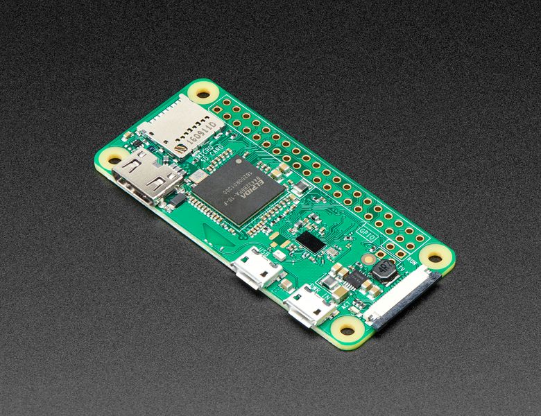
NOTE: This build is alpha quality and is for experimental use. It is missing features and has known issues.Raspberry Pi Zero W Is the first small size (Wifi enabled) Raspberry Pi’s single-board computers. This is the predecessor of Raspberry Pi Zero 2 W with the same form factor.The board incorpo...
hard pike
sullen coral
I have installed the bare metal image of Circuit python from the official site o...
Hi, please don’t cross post. Pick one channel that is closest to your issue and wait for a response. Cross posting makes it more difficult to get good help and is also strongly discouraged. This channel is a good channel for this issue.
sullen coral
hard pike
Hi, please don’t cross post. Pick one channel that is closest to your issue and ...
Sure.. thanks. New to this forum and was not sure what to post it on. Will keep in mind
rotund pivot
danh answered in #help-with-circuitpython message
midnight flume
My NVME Base arrived today. Will start putting the Pi 5 together and designing a 3D printed enclosure.
Most of the commercial cases I've seen don't account for the NVME base. I have a feeling it might become the stock configuration for a lot of people so having a 3D printed enclosure that accounts for it should be helpful. I think there are a few designs that do account for it but the plans I have for the enclosure design are unconventional.
modern matrix
the pimoroni NVME base looks nice. I've got an m.2 PCIe USB-C controller I'd like to try with it; I never got it properly working with a Pi CM4 because my carrier board's m.2 slot wasn't big enough to hold a 2260-sized card.
tulip barn
I'm really happy with mine. installed fairly quickly, then i just sudo dd the micro sdcard to the nvme, set boot order to nvme and has been working flawless
 willow lintel
@tulip barn is sudo dd also a good way to back up an nvme drive to SD card while the system is on? I have a Linux SBC with and an onboard flash drive that I’m terrified will get corrupted every time the power goes out but I don’t know how to backup a Linux system while it is on
tulip barn
willow lintel
<@452973999329116182> is sudo dd also a good way to back up an nvme drive to SD ...
I’m by no means an expert. I use dd in my crontab of my main project to backup daily while it’s running. Note that dd will copy complete information, including empty space so you’ll want to adjust the output size if you’re input drive or partition is larger than your output
zenith crystal
willow lintel
<@452973999329116182> is sudo dd also a good way to back up an nvme drive to SD ...
yes -- in fact, that is exactly one of the recommended ways to switch from the SD card to a USB drive (there's an extra setting you have to boot with before the USB drive works that I don't remember off-hand)
 red yoke
hey, I have an oldish Raspberry Pi 2B+ I'm trying to add a fan control to, using a DHT for temperature measurement and a PWM fan
I got both DHT and PWM working individually (DHT read success rate about 60-90%), but I'm unable to read the DHT if I start using PWM
DHT on pin 17 and fan is on pin 13 (fan rn substituted with a led for testing)
here the simplest example I tried doing through python console:
import board
import adafruit_dht
import pwmio

dhtDevice = adafruit_dht.DHT11(board.D17)
dhtDevice.temperature
> 21
fan = pwmio.PWMOut(board.D13, frequency=5000, duty_cycle=0)
dhtDevice.temperature
> A full buffer was not returned. Try again.
its probably something obvious but I'm new to this and didn't have much luck on google so decided to try this out
not sure if this was the best channel but thought it's probably some quirk with raspberry pi I'm not familiar with
until now I've just used it as a small home server, first time using the GPIO
red yoke
hmm nvm the problem is probably somewhere else. I rebooted and rewired everything and now it works, although the success rate for the data read is still significantly lower when the PWM is enabled, from like 70%->20%
although, trying to run the whole logging script suddenly it doesn't manage to read it even once (allowed it to try it about 50 times)
steady rose
consider upgrading away from the DHT:
https://learn.adafruit.com/modern-replacements-for-dht11-dht22-sensors
red yoke
that'd require me to order them, mostly trying to work with stuff I got long ago but I suppose
willow lintel
zenith crystal
yes -- in fact, that is exactly one of the recommended ways to switch from the S...
So if I back up my drive to a SD card, I could restore it by first getting the onboard os to a point where it boots, then switching to boot from the SD, then dd the SD card back onto the flash and switch the boot order back? Any guides that explain this well?
zenith crystal
willow lintel
So if I back up my drive to a SD card, I could restore it by first getting the o...
once you're booting from a USB drive, why would you want to use the SD? and I'm not quite following you -- it's an "either or" for booting: either SD or USB (once it's set to allow that)
willow lintel
zenith crystal
once you're booting from a USB drive, why would you want to use the SD? and I'm ...
I’m not starting from an SD card. In the case of corruption, my flash/usb/nvme drive is unbootable until I reflash it with the ground zero image I can get online. Instead of spending days reinstalling and reconfiguring everything I have setup, I want to clone my backup image from the SD card back onto the flash (but presumably I can’t do that while running from flash) so I’d have to switch the boot order to the SD backup before transferring the image, yes?
zenith crystal
willow lintel
I’m not starting from an SD card. In the case of corruption, my flash/usb/nvme d...
that's one way of doing it, but typically all of the major changes you're going to be making to the syatem aside fro a few packages are all going to be in the "user home", so completely re-cloning the drive as a backup is probably overkill
willow lintel
zenith crystal
that's one way of doing it, but typically all of the major changes you're going ...
I’m ok with a little overkill if it means not having to fuss with things if/when the flash gets corrupted
 mystic light
I'm trying a blinka install on a fresh Rasp4, Raspbian OS 64bit and running into a problem with the command:
pip3 install --upgrade adafruit-python-shell
error: externally-managed-environment
I thought I was following the guide correctly but can't seem to figure this part out
ah, nevermind, I see the Bookworm updated instructions, I'll give that a go
mystic light
no discotools for raspberry pi?
vocal lava
what happens when you try and pip install it?
lean kiln
5% off pi's at thepihut.com (UK) and 10% off kits. Ends sunday. Both sizes in stock. Looks like pishop.us has good stock (no discount though) if across the pond.
mystic light
vocal lava
what happens when you try and pip install it?
Looking in indexes: https://pypi.org/simple, https://www.piwheels.org/simple
ERROR: Could not find a version that satisfies the requirement discotools (from versions: none)
ERROR: No matching distribution found for discotools
nevermind, for some reason I was using discotools instead of discotool. installs fine
modern matrix
I know there's an official Raspberry Pi 5 USB-C power adapter with a wacky 5V/5A output, but is anyone making a USB-PD cable that sources 25W+ using a normal, common USB-PD power profile and exposes it as 5V/5A over USB-C/USB-PD for the Pi 5?
I've got a couple of those cool Adafruit USB-PD trigger boards that I could connect to buck converters, but it seems like this should be an off-the-shelf product?
broken shuttle
modern matrix
I've got a couple of those cool [Adafruit USB-PD trigger boards](<https://www.ad...
It quickly becomes problematic because, like every pi, the voltage requirements are actually out of spec for USB.
modern matrix
my understanding is that it's allowed in the spec; a source can advertise the 5V/5A profile, but a device can't require it. which is probably why the Pi 5 also works with a 3A source by reducing max output on its USB host ports. so a PD-to-PD adapter that translates a common profile (maybe 12V/3A) to a less common one (5V/5A) seems possible within spec.
 waxen citrus
Hello, did anyone manage to get the ws2812b on a raspberry pi 5 running? The neopixel libraries are due to hardwarechanges not working. Is someone working on this ?
zenith crystal
probably
broken shuttle
modern matrix
my understanding is that it's allowed in the spec; a source can advertise the 5V...
I'm referring to the voltage tolerance. 4.85V is still in-spec for the 5V rail, but a pi will almost certainly brown out at that voltage.
 silver flume
I am copying what I said in #help-with-circuitpython
I am wondering is there a full documentation how can I GitHub Action/CI my groupwork of hardware and software implementation of the IoT device? I have tried sleuthing the Adafruits' own Github repos of how they have done our tests, but I use the Blinka' with Micropython flavour of firmware? I have tried reading the Micropython Testing chapter of documentation but that makes me wonder and force me to somehow figure out how can I clone, copy it and run in everytime.
humble marsh
silver flume
I am copying what I said in <#537365702651150357>
I am wondering is there a fu...
what is your reason for using Blinka with MicroPython istead of using CircuitPython directly/
modern matrix
in a quick test, it looks like the Raspberry Pi 5's RP1-based USB controller doesn't have the bug in the Pi 4's VL805 controller where it rejects connecting more than one or two USB audio devices at a time with a "not enough bandwidth" error. nice! I was hoping for this. something reviewers don't test for.
I was able to connect 5 USB audio devices with no errors. it was a quick test; I'll need to follow up by trying to drive them all simultaneously. I've got high hopes, tho.
wonder what the 5's max underclock/undervolt is...
snow timber
Ideas on how to fix Ubuntu 23.10 on pi 5 dropping usb nic while under load (dmesg shows xhci-hcd stopped responding) reboot will get the nic back, but not very useful nic if it drops out.