#help-with-arduino
1 messages · Page 108 of 1
 waxen hawk
 cedar mountain
It's also pretty easy to crimp RJ12 cables, so you can cut open a DB9 serial cable and put a RJ12 connector with the right pin ordering on it.
waxen hawk
one last question, do modbus work over rs232? I never heard of modbus, its seems a little bit like uart.
 north stream
It does look like the adapters are still made: https://www.winford.com/products/mjd9.php
waxen hawk
cedar mountain
It's also pretty easy to crimp RJ12 cables, so you can cut open a DB9 serial cab...
can I just use a rj12 and use only the lines needed for Db9?
north stream
Yes, it's only 3 wires.
waxen hawk
DB9 has only 3 wires?
north stream
There are 9 wires, but that link only uses 3 of them (receive, transmit, and ground)
cedar mountain
waxen hawk
one last question, do modbus work over rs232? I never heard of modbus, its seems...
Modbus is a protocol that runs over a number of types of serial links... RS-232, RS-485, etc. It just describes what bytes to send in order to do particular commands, but sending the actual bytes would be handled by the UART.
waxen hawk
Ah i see. perhaps maybe I am getting confused because in this document, modbus for rj12 uses 6 specific lines....
north stream
If you look at the 6 pins, two of them are power (not needed for an RS-232 link, they're just there to power the Bluetooth module), two of them are ground, and the remaining two are receive and transmit.
cedar mountain
As an analogy, the RJ12 pins and RS-232 are like a telephone, and Modbus is like "speaking English". One establishes a communications link, and then the other is a protocol to send meaningful information on that link.
waxen hawk
Thank you! make senses. The document mentions of rs485. What is that,? is that the specific protocol for rj45?
yep one is a communication protocol and the other is a physical connector
cedar mountain
RS-485 is a similar UART-based link, like RS-232, but it allows multiple devices to share the same wires and take turns talking, instead of only having a point-to-point link.
north stream
RJ45 is another phone company standard (like RJ12). It's not really RJ45, it just uses the same connector (which is an 8P8C). RS485 specifies signalling voltages (which are similar to RS232) but not protocol. It's like RS232 but supports multiple transmitters.
Since your unit does not have an 8P8C connector, you can ignore that anyway.
cedar mountain
(CAN is also mentioned in that document. It's yet another multi-device signaling standard, often used in automobiles.)
waxen hawk
Great. Thanks! This has been extremely helpful. I think I get a gist what I need to get and build. Modbus looks straightforward because I've written uart then.
waxen hawk
cedar mountain
(CAN is also mentioned in that document. It's yet another multi-device signaling...
yeah I should learn about CAN at some point. haven't had a chance tho ...
 upper flicker
I have a LSM6D33 breakout which I've connected to an RP2040 feather with the stemma qt connector. I'm using the adafruit libraries for everything, and i'm trying to get the example working, but its saying theres not chip. I think the issue is that the stemma connector is on i2c1 and not i2c0. Anyone know how to make busio / the lsm6ds33 library use i2c1 and not i2c0?
cedar mountain
Typically you can optionally pass in a Wire object parameter to the library in its constructor, which in this case would probably be &Wire1.
upper flicker
I tried this if (!lsm6ds33.begin_I2C(0x6A, &Wire1)) but its still not working
Wait i got it to rescan until it connected and now its working!!
 elder hare
@obtuse spruce hi are you back? 🙂
elder hare
anyone help with this -> https://discord.com/channels/327254708534116352/963056091862822962
 proud mulch
SOLVED. I used female-male Dupont cables to selectively connect each pin from the MKR1010 to the Carrier. The solution appeared when, with the RED cable from the Battery JST cable (carrier to MKR1010) cut off and only the BLACK cable connected, and, connecting ONLY the GND pin, the MKR1010 lit up! There's only ONE way that connecting two GND cables creates an electric circuit: if one of them is NOT GND. The color coding in the Opla Kit -provided JST cable is inverted. Sure enough, when placing the mechanical switch on the BLACK cable, power is completely cut from both the MKR1010 and the Carrier. Either Arduino's cable supplier needs better quality control or someone at the cable crimping station though it would be funny. Of course the color inversion is only relevant when adding a mechanical ON/OFF switch, otherwise, everyone will continue believing that BLACK is GND. Ignorance is bliss.
 hasty ravine
Hey! I have the LoRa rfm9x Featherwing (https://learn.adafruit.com/radio-featherwing) and I want to connect it with the arduino nano 33 BLE (http://store.arduino.cc/products/arduino-nano-33-ble). I have a code ready that is working fine on Adafruit feather HUZZAH with esp 8266. How do I wire them? I've tried connecting the IRQ CS and RST pins to 3 of the digital pins on arduino. After changing the defines it doesn't work either. How do I wire them?
 elder hare
anyone who can help on #963056091862822962 ? 🙂
north stream
hasty ravine
Hey! I have the LoRa rfm9x Featherwing (https://learn.adafruit.com/radio-feather...
After looking around some, it seems there are some weird issues with interrupts on that board.
hasty ravine
north stream
After looking around some, it seems there are some weird issues with interrupts ...
So what does that mean. It doesn't work with this board?
I realized that I didn't connect the SPI pins of the radio module to my board
 zenith spindle
Help Please, I hope I'm in the right place if not I apologize. I am trying to create an iPad Bluetooth controller (currently having some success with Bluefruit Feather 32u4). I need a lot of pins, so I am using a matrix setup. But i need it to send a modifier key with a regular key (CTRL-Q for example) under 1 keystroke. Seems 1st is there a program that already does this so I'm not trying to reinvent the wheel (I have looked for weeks haven't found anything). 2nd I am not a programmer so I could use some help if someone can steer me in the right direction.
 native dagger
Is there a ReadTheDocs equivalent for adafruit arduino libraries?
 gilded swift
Usually a doxygen GitHub site
native dagger
ah ok
thx
Hm, this page: https://github.com/adafruit/Adafruit_DS1841 says there's docs, but how to get to them?
native dagger
ahh thanks
native dagger
Looking at this product, I can't tell if there's a way to say like "Set the resistance to this (or as close as possible to this) value" or not.
It seems like you can just set the wiper? And you have to have like a LUT to figure it out?
gilded swift
Looks like it
native dagger
haha
I think this may be out of scope, and not as helpful as it seems, so I'll just do something else!
gilded swift
native dagger
I think this may be out of scope, and not as helpful as it seems, so I'll just d...
You can always fork the repo and add what you want
Would be fairly straight forward
gilded swift
Yeah, and could be useful to other people too
native dagger
Yeah, maybe I'll order one of these and see what I can whip up.
Thanks for the encouragement
gilded swift
🙂
native dagger
now I just have to have more time to myself!
gilded swift
I feel that
My time is spent working, holding/feeding/changing my son and not much on actually doing anything technical lol
native dagger
nooooo I forgot to order a stemma connector!
Yeah I don't have any family, but I just work too much and commute too much.
gilded swift
😵
native dagger
well, USPS is getting another 4 dollars from me
gilded swift
Each certainly has its benefits
I forgot to order buttons from Adafruit so I spent $12 on Amazon along with a few other necessities I needed
Got a pack of like 268 assorted buttons
Which is fine.. I would have just preferred to go through Adafruit
native dagger
yeah I love shopping with adafruit. Makes everything easier.
Plus I hate buying anything on Amazon.
gilded swift
Same, but sometimes it’s just easier to do same day on stuff (though I didn’t do that this time)
native dagger
The experience is not great. Even if you know exactly what you want, their "equivalent merchandise" policy can get you.
gilded swift
I’ve not had issues with getting something different than I’ve ordered
But I don’t order wild items or often so..
native dagger
I don't like risking it. I do use it sometimes, for things that there aren't equivalent merchandise for, but I don't like the risk involved, at all.
e.g. if I could afford a Nintendo Switch, I'd consider using amazon.
gilded swift
I went to target for my switch
native dagger
They have them rn and it's tempting
I want to play the new pokemon games real bad.
gilded swift
I sometimes buy digital games off Amazon
native dagger
Yeah stuff where they can't get ya'
gilded swift
I preordered Pokémon legends Arceus on Amazon and got a cool digital gift
Anyway, should move this to off topic before we get too far off topic 🙂
native dagger
you're right
elder hare
Running my Cylon pattern with 4 pixels, what happens when i set Tail to either DUST or SOLID the tail starts at the front pixel of the Cylon Pattern and messes up the Palette colors as it overlaps the colors of the 4 pixels, can i offset the tail to only occur behind the Cylon bar?
void Settings::applyTailEffect(CRGB* leds, int size)
{
    switch (PatternTail)
    {
        case DUST:
            for (int j = 0; j < size; j++)
            {
                if (random(10) == 1)
                {
                    leds[j].fadeToBlackBy(PatternFadeAmount);
                }
            }
        break;
        case SOLID:
            fadeToBlackBy(leds, size, PatternFadeAmount);
        break;
        case OFF:
            fadeToBlackBy(leds, size, 255);
        break;

        default:
        break;
    }
}
 stone hamlet
Everytime I send informations to my Feather M0 express she is automatically disconected. And when i want to connect it back I've to reset it. So I can't know what's going on ont the feather.
Do someone know wat I can do to resolv this?
(you can @ me)
cedar mountain
stone hamlet
Everytime I send informations to my Feather M0 express she is automatically disc...
Is your code crashing in processing the received message, maybe?
stone hamlet
I think not
even when I send a easy one (for example juste a led that turns on and off) she is also disconected
cedar mountain
Maybe it would be useful to have a LED constantly blink while your code is running, so you can tell if it's still "okay" even if it gets disconnected.
stone hamlet
that's a good idea😃
 lost kraken
if i write this, will it assign that to D2 or A2????

 leaden walrus
pinMode(A2, INPUT);
leaden walrus
what arduino board are you using? worth double checking there's nothing unique about it.
leaden walrus
ok, above should work then
for the the digital pins, you typically don't include the leading D
so just pinMode(13, OUTPUT); for example
lost kraken
I've also seen this though which confuses me (it uses the pin with analog read in the tutorial)

 leaden walrus
are you wanting to use the pin for analog or digital input?
lost kraken
in the tutorial it uses this to refer to A1, so im wondering if the tutorial is just plain wrong?
leaden walrus
elsewhere in the code, is it calling digitalRead() or analogRead()?
lost kraken
yes it calls analogread
leaden walrus
ok, then sounds like an analog input example
for analogRead(), you can typically get away without needing to call pinMode():
https://www.arduino.cc/en/Reference/AnalogRead
lost kraken
does the IDE implicitly understand that it's an analog pin then?
leaden walrus
yes
pin: the number of the analog input pin to read from (0 to 5 on most boards, 0 to 7 on the Mini and Nano, 0 to 15 on the Mega)
pinMode(A2, INPUT); or pinMode(A2, OUTPUT);
you'd typically do something like that if you wanted to use the pin for digital i/o, and then later digitalRead(A2); etc.
north stream
While it will generally let you call analogRead() on a digital pin (like D1), it isn't particularly useful to do so.
 rough torrent
I believe analogRead calls pinMode to set it as input for you, but it's nice "documentation" on what pins you are using
 burnt rover
as far as i'm aware, there's nothing special about pin 11 on the itsybitsy m0, right? it's just a normal old gpio?
i've got the most confusing behavior with that pin right now. i have it set up just as a digital input, connected to a switch w/ an external 2k2 pull up resistor and 100pF smoothing cap. it's using the switch on an encoder. when i press the encoder, the whole program crashes. if i change the pin (software is using a macro so nothing else in code changed), it works fine, which suggests it's a problem with the pin... but if i use a button instead of the encoder, pin 11 works. so something about the specific combination of this encoder switch and pin 11 is broken
also checked with a multimeter + oscilloscope and the button and encoder switch are behaving identically
even if it turns out that the pin is fried and nothing's wrong with my code/hardware, it's still absurd
 stable forge
burnt rover
i've got the most confusing behavior with that pin right now. i have it set up j...
stable forge
burnt rover
i've got the most confusing behavior with that pin right now. i have it set up j...
when you say "crash", what do you mean exactly?
Is this one of our rotary encoders?
burnt rover
totally freezes - no output on serial monitor, LEDs which are blinking freeze in place, whole Arduino IDE becomes unresponsive until i unplug the board
burnt rover
stable forge
Is this one of our rotary encoders?
no, it's one from Digikey. i can grab the part number if that's helpful
stable forge
make sure you are not accidentally shorting 5V to ground or something like that when you press the switch. Make sure the terminals you think are the switch are actually the switch (e.g. test with ohmmeter)
since a regular button is working, I suspect something about the wiring to/for the encoder switch
burnt rover
i had checked that, but i'll try again. maybe also set up a basic LED indicator
that was my thought too, but it works with the exact same circuit but connected to other pins on the board
stable forge
maybe upload your program. Use the + to the left
burnt rover
every other switch works as expected except SW1, but i've tracked that issue down already
stable forge
did you change the encoder switch off 11? I see no 11 in the program
burnt rover
oh yeah, sorry. it's SW6, i'd changed it while trying to debug
stable forge
looking at pin assignments in arduino...
stable forge
burnt rover
oh yeah, sorry. it's SW6, i'd changed it while trying to debug
I don't see anything that might cause this -- no pin errors, etc. somewhat at a loss
burnt rover
yeah i'm really confused lol. well, i needed to order another round of pcbs anyway, so i'll just change the pin assignments and move on with the project lol
thanks for the help!
stable forge
yw!
elder hare
im at a loss here, im running my pattern Cylon here and when i set a tail fade on either (DUST or SOLID) the palette gets messed up (im running the Rainbow palette) now if i set the tail fade to OFF the pattern and palette works fine :S
Pattern including all function for tail and palette is here (to big for discord):
https://www.toptal.com/developers/hastebin/xeveyayeyu.cpp
Hastebin is a free web-based pastebin service for storing and sharing text and code snippets with anyone. Get started now.
 pine bramble
when I convert millis() to seconds how do I get seconds with decimal value
Where can I start learning about Arduino code
I have some prior history in c and python
What are some good resources to learn from
north stream
pine bramble
when I convert millis() to seconds how do I get seconds with decimal value
You can do it explicitly by converting millis() to float and dividing by a thousand, or use the casting rules of the compiler by dividing by the floating value 1000.0, so the compiler will "promote" the other value to float before doing the division.
Or you can just do both (the result will be the same): ```arduino
float seconds = (float) millis() / 1000.0;
 humble folio
Well, somewhat related to my question in #help-with-linux-sbcs, here is a different idea. Can I connect a Flash Drive to a Arduino that.. well stores data such as PDFs and Programs and a USB Port to connect to a PC? It should function as a USB drive but run a program off of the flash drive automatically when connected. Is this possible?
north stream
humble folio
Well, somewhat related to my question in <#538149593246859313>, here is a differ...
Some of the AdaFruit boards work like this, providing some flash storage as a filesystem via USB and to the microcontroller.
stable forge
humble folio
Well, somewhat related to my question in <#538149593246859313>, here is a differ...
you can add an SD card, not a USB flash drive (unless you use a USB host card). SD card is much easier and better supported
you can then have the Arduino act as a flash drive (because that is a USB peripheral). You would not use a classic Arduino, but something with native USB support. I'm not sure exactly what your use case is.
stable forge
pine bramble
Where can I start learning about Arduino code
https://learn.adafruit.com, https://arduino.cc, there are many, many Arduino tutorials on the web. https://www.amazon.com/Programming-Arduino-Getting-Started-Sketches/dp/1259641635/
https://www.amazon.com/Exploring-Arduino-Techniques-Engineering-Wizardry/dp/1119405378/
If you have Python experience already, CircuitPython shoudl be easy to pick up: https://learn.adafruit.com/welcome-to-circuitpython
 twilit pasture
Hi all, I had quite a confusing set of events happen with an Arduino Nano 33 BLE -- trying to figure out if the board is completely toast or not, or if there's a way to revive it:
- it started by mis-behaving, and not showing up as a serial port on my computer (my program on it still ran, and I could verify that, but in bootloader mode, it could not be programmed), in fact, in bootloader the board got fairly warm
- I thought the bootloader might be corrupted, so I tried to re-flash it, and then my program was gone, and the bootloader still would not show up as a serial port on my computer
- I tried again to burn the bootloader (this is with a Raspberry Pi Zero with OpenOCD btw), and now the power LED won't even turn on, but I'm still able to connect to it with OpenOCD and what not.
Is there a way to diagnose if the MCU is bad or not via OpenOCD? I have a BMP on the way so that may provide some insight.
Also, is this an okay channel to post in? Was planning on starting a thread here 🙂
north stream
The board getting fairly warm probably does mean it has hardware damage
twilit pasture
Okay, is it common to get "partial" damage? I'm just confused how I caused it and don't want to damage my new board 😂
I'd love to validate the hardware damage somehow, I know the power circuit is alright
 woeful igloo
Programming an LCD display

whenever i plug the 5V wire in, the board turns off entirely
but when i unplug it, it turns on
woeful igloo
any idea why this happens?
 livid osprey
@woeful igloo You probably have a short-circuit between 5V and GND. I would try to remove as much of the extra solder off the tips of the pins before trying again.
woeful igloo
livid osprey
<@880036918451142737> You probably have a short-circuit between 5V and GND. I wo...
i c, ill try that now
@livid osprey but how will i remove the thing?
i dont think its even there
livid osprey
I think you just have to try to remove the solder from the tips of the display pins. If you have a solder sucker or copper wick, it shouldn't be too hard.
woeful igloo
livid osprey
I think you just have to try to remove the solder from the tips of the display p...
the only thing i found is a little bit of corrosion on the black cover for the headers
but im pretty sure that affects nothing
@livid osprey there seems to be no corrossion, so im not sure whats causing the issue
livid osprey
woeful igloo
i c, ill try that now
No, these globs of solder might be causing a short circuit. What corrosion are you looking for?
 woeful igloo
livid osprey
No, these globs of solder might be causing a short circuit. What corrosion are y...
woeful igloo
livid osprey
No, these globs of solder might be causing a short circuit. What corrosion are y...
what am i supposed to do about them?
livid osprey
Remove the extra solder, you have too much.
woeful igloo
livid osprey
Remove the extra solder, you have too much.
desolderings gonna be a pain
i dont really know how to desolder but ill try
 vague horizon
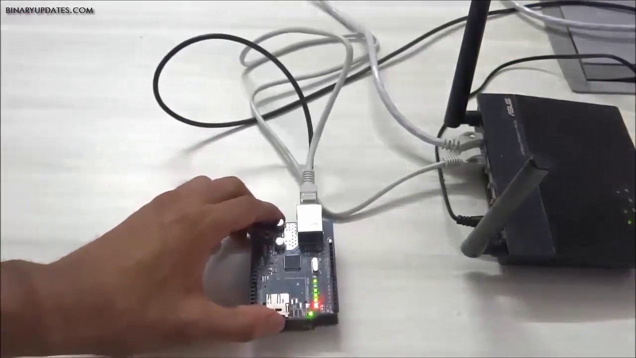
Hello! I've been trying to make a simple webserver in order to launch a model rocket from a website instead of a controller by using an ethernet shield on my MEGA2560. However, whenever I try to print the local ip address for the server, it keeps giving me 0.0.0.0. I've tried applying pressure to the ICSP pin connections, and while it makes the process quicker, I still end up with 0.0.0.0. I've tried assigning an IP address as well, but it doesn't work either. Does anyone know how to fix this? Thank you so much in advance! I used the code from this video: https://www.youtube.com/watch?v=pyKPivef3ks .

This lesson is about Arduino Ethernet Shield Webserver. We will build small webserver using Arduino Ethernet Shield. This webserver will allows us to control LED connected to Arduino. Ethernet Shield will allows us to provide internet connectivity to our Arduino Project. We will build really cool internet of things enable application using Ardui...
north stream
Many webservers listen on 0.0.0.0, which basically means "any interface". I'm unsure why pressure on the ISP pins would change anything.
 hollow wigeon
 rough torrent
Picture is unclear (for me on a phone at least) maybe you should try pressing the copy error messages button and deleting some of the non error messages and posting it here
 latent nacelle
Hello everyone. I am trying to connect this device: https://www.alibaba.com/product-detail/Fst100-2006-Fst100-2006-Firstrate-FST100_62129359792.html?spm=a2700.galleryofferlist.normal_offer.d_title.110b5de76JlZvo&s=p to an Arduino. It says the output signal is "RS485 output (Modbus protocol) 4~20mA with DTU, wireless transmission". Can anybody direct me towards resources where I can learn how to read the output signal with an Arduino? Sorry but I am very new to electronics and I don't even know where to begin. Any advice is helpful, thanks
Firstrate Fst100-2006 Rs485 Smart Modbus Garden Fdr Soil Moisture Temp Meter Sensor 0%rh-100%rh 1.2w 0.4w Direct Lead - Buy Moisture Meter Soil,Fdr Soil Moisture Sensor,Garden Soil Moisture Sensor Product on Alibaba.com
north stream
I think that's three different outputs: RS-485 (which is a voltage output), 4-20mA (which is a current loop output), and wireless. Depending on which wireless standard it is, that or RS-485 is probably the easiest to hook to an Arduino.
 desert bough
is there any documentation for the neotrellis m4 arduino library?
 signal salmon
Is this the correct place to ask for help with programs using arduino IDE but not on arduino hardware?
I am trying to get the MLX90640 thermal camera example code working on a MaixBit device, it compiles but says MLX90640 not found... I know that I2C is wired correctly, and the device is recognized when I run an I2C scanner project but the simpletest example says not found.
I also enabled the MLX90640_DEBUG and DEBUG_SERIAL
cedar mountain
It looks like the simpletest example program is running the bus at 800kHz, whereas a scanner would probably default to 100kHz. Could that be the difference?
signal salmon
The scanner does not explicitly set the speed as far as I can tell
signal salmon
cedar mountain
It looks like the simpletest example program is running the bus at 800kHz, where...
The simpletest program does not seem to set the bus speed either?
cedar mountain
I may be looking at a different code version than you're running, then.
signal salmon
Just found https://forums.adafruit.com/viewtopic.php?f=19&t=182536&sid=727a5803cb55bf0d687201477935dff4&start=15 which seemed to ended with RMA being suggested, which I want to avoid...
I am using version 1.0.2, downloaded through arduino ide
signal salmon
cedar mountain
I may be looking at a different code version than you're running, then.
This is the only line I can see which would set speed if it were not commented out: https://github.com/adafruit/Adafruit_MLX90640/blob/a853d67cf3076ed81a9664d3dd5f0329551520e3/Adafruit_MLX90640.cpp#L22
If the sensor is actually broken it would explain why it was not working with the rust drivers I found...
cedar mountain
signal salmon
This is the only line I can see which would set speed if it were not commented o...
Agreed, yeah. Different simpletest version, so never mind the bus speed angle.
signal salmon
Yeah, thanks for checking though! Am contacting Digikey support now.
 boreal trench
Hello guys, I want to use these air pumps((https://www.adafruit.com/product/4699)) to switch the inflation and deflation of a balloon. But how can I connect them to Arduino Uno? The example only shows the usage of Adafruit playground, of which pins are quite different😫
 vivid rock
boreal trench
Hello guys, I want to use these air pumps((https://www.adafruit.com/product/4699...
vivid rock
boreal trench
Hello guys, I want to use these air pumps((https://www.adafruit.com/product/4699...
you would need a motor shield - the pump opetates as a dc motor.
But why Uno?niwadays there are many cheaper and more powerful boards than Uno
livid osprey
Why not an uno? It’s plenty enough to control a single pump, and often times it’s what people have on hand.
Sure you can get better these days, but if you already have something gathering dust, wouldn’t you want to utilize that first if you could?
north stream
You don't even need a motor shield, just a power transistor.
burnt rover
burnt rover
i've got the most confusing behavior with that pin right now. i have it set up j...
i bought another ItsyBitsy m0 to see if the issue was just with that one board, and the same thing happens. i don't think it's my software, but i can't find anything wrong with my circuitry:

any movement of the encoder or pressing the button causes the board to freeze until reset
burnt rover
it's definitely in the hardware, because even this super simple blink sketch freezes when i move the encoder:
#define LED_HPIN    A1
#define LED_LPIN    27u


void setup() {
  pinMode(LED_HPIN, OUTPUT);
  pinMode(LED_LPIN, OUTPUT);

  digitalWrite(LED_HPIN, LOW);
  digitalWrite(LED_LPIN, LOW);
}

void loop() {
  static bool led = false;

  led = !led;
  digitalWrite(LED_HPIN, led);

  delay(500);
}
Your schematic looks fine (assuming the resistors are typical pullup values like 10k), so I suspect that it doesn't match how things are wired in reality.
burnt rover
they're 2k2. and it's a PCB, so it should match the schematic exactly, and i've also done continuity tests to make sure things are going where they should
the encoder is connected to 12 and 13, and the switch to 11
cedar mountain
Don't know what to tell you. Something is definitely wrong with the board, so it's just a question of finding out what. At this point, the best approach is to ask yourself, "Okay, which one of my assumptions that I am totally sure of ... have I not actually tested?"
burnt rover
hm
setting pin 13 (on board LED) to input fixed the encoder problem, which makes me think that either something is shorting on 11, or there's some sort of protection circuitry on the m0 that i'm triggering
i'll do some more tests. it's just perplexing that this one switch, on this one pin, would cause issues
thanks for taking a look
cedar mountain
Yes, if you were hooking the encoder to an output pin that was driving high, it would be hard-grounded by the switch, causing the MCU to likely freak out as power got shorted to ground.
burnt rover
unfortunately, setting pin 11 to input doesn't change anything
is it possible that something in the bootloader is taking control of 11 for some reason? i did notice that i had to do a bit of trickery to gain control over the DotStar, which I know the bootloader uses, so it could be forcibly setting 11 to an output
cedar mountain
Couldn't say offhand, I'm afraid. One way to check would be to put a weak pulldown on the pin and monitor the voltage during boot.
burnt rover
well, i’ve now gotten it so that a normal button breaks the board, not just an encoder. progress, i guess?

- doesn't freeze the program if i plug it in to any other pin
- ive simplified the circuitry & program as much as possible
- tried different resistor values
- checked pin 11 on an oscilloscope, both while running and on reset. no output
documentation doesn't say anything special about pin 11. changing boards does nothing... i'm out of ideas
would someone else with an ItsyBitsy M0 be willing to test this out and see if they can reproduce it? same breadboard layout as above, 100pF cap and 2k2 resistor
cedar mountain
burnt rover
would someone else with an ItsyBitsy M0 be willing to test this out and see if t...
Very weird. Did you check for a short between pin 11 and 13? Wondering if your breadboard might be defective or something bizarre like that.
burnt rover
just checked, no short
i'll just cut the traces for now and design the next round of PCBs to use different pins, but it's really quite absurd
pine bramble
Can anybody please have a look at this problem and guide me a bit?
i am using Arduino Nano
The first reading "31" is the LM35 temperature sensor reading in celcius connected to A0 But when i try to read any other Analog pin, (for example A5 as shown in the video) the temperature value starts fluctuating.
The sensor which is connected to A5 is ACS712 20 amps module
There's not even the current passing through it yet but still it's causing this
I tried changing the PIN but still same results
cedar mountain
I'm not sure whether this is what is happening, but if your analog inputs are very high impedance (weak current), you may be getting hurt by the ADC multiplexer switching inputs. With only one input, the ADC might be able to build up enough voltage on the sampling capacitor to get a correct reading, but when it has to switch back and forth between multiple inputs, that voltage gets reset, and a weak signal would take some time to come back to equilibrium. You might try adding a little capacitance on A0 and seeing whether that changes anything.
pine bramble
I have this capacitor with the value of 10 microfarad, Can i try adding this one?
 cedar mountain
Yep, that's probably larger than needed in a final design, but it should let you know whether this sort of thing is going on or not.
pine bramble
So.... Like this? Just making sure with the diagram first so I don't mess up the circuit😅

@cedar mountain is that correct or.....do i need connect that anywhere else?
cedar mountain
Yep, that's correct.
Although with a quick scan of the LM35 datasheet, this shouldn't be an issue if you have it hooked up directly like that, as it claims around a 0.5-ohm impedance with a built-in amplifier.
pine bramble
i am still gonna give it a try cause from the coding side, i've checked everything
My soldering iron is getting warm up meanwhile i do need to mention that when i read any other Pin (for example A3 which doesn't have anything connected to that) instead of A5 which has ACS712 current sensor connected
the Temperature value doesn't fluctuate
Hmm, Added the capacitor but still the same fluctuation
cedar mountain
Makes sense given the datasheet, but I'm not sure what else might be going on, apart from software weirdness.
woeful igloo
help, everytime i connect vcc to 5V my arduino just turns off
theres nothing wrong with my display module however
if i connect more than 3 pins in general, the same happens
nvm, its just GND and 5V/VCC
but im not sure why this is happening?
north stream
Normally it will be off until it gets 5V, not the opposite. Or is it getting 5V via some other source (USB?) and switches off when you supply 5V via another route?
woeful igloo
north stream
Normally it will be off until it gets 5V, not the opposite. Or is it getting 5V...
im powering a 128x32 display, and this is how i wired everything

when i disconnect the GND, the arduino powers on
same thing happens for the 5V/VCC pin
when i have either the GND or 5V/VCC plugged to the display, my arduino turns off
and it appears as if its not connected to my computer when i do so
im not sure whats causing the issue here, but i do know that i did melt the IOREF and RESET slot accidentally while soldering, but i dont think that should affect anything
boreal trench
north stream
You don't even need a motor shield, just a power transistor.
Yes, I succeeded in driving one pump by using a transistor and a diode. Maybe for two, just double it.
livid osprey
woeful igloo
help, everytime i connect vcc to 5V my arduino just turns off
Did you have any luck removing the excess solder from your pins?
woeful igloo
livid osprey
Did you have any luck removing the excess solder from your pins?
i used another display to see if it was the excess solder or the board itself
the display came pre-soldered so thats neat
its something with the board alright
livid osprey
Hmm, do you have another board you can test with?
woeful igloo
i have the pi pico but its not soldered so i cant use it
i feel like the USB is conflicting with the 5V and GND pins
but im not sure how to fix that
livid osprey
Perhaps. Do you have a barrel jack power supply?
woeful igloo
livid osprey
Perhaps. Do you have a barrel jack power supply?
the what?
no, i dont think i have that.
nvm, i figured it out
the GND and 5V pins were connected to the same rail, causing a short circut
 flint spruce
If I plug a USB power bank into an Arduino's power input, and then wire some NeoPixels into the 5V pin, will they be able to draw from the power supply or would I still need to wire them directly to it?
native dagger
It's a better idea to wire directly for more than a small number of pixels
Most UBS ports on PCs top out at 500 mA. Neopixels on max brightness require 60mA per pixel. I think your application would easily draw over 500 mA, even if you're not using max brightness.
flint spruce
I see, you have any recommendations on a good way to split a USB power connector between an Aruduino and 2 NeoPixel shields?
native dagger
USB from a computer?
flint spruce
Oh no I meant from a USB power bank, so it can be portable
I have an Anker one that is pretty hefty and I was wondering if it would work
native dagger
Oh it should work. It should be possible to do without too much trouble, but I'm not able to devote a ton of time to it atm
flint spruce
Okay gotcha, I just wanted to know if it was at all possible, thanks!
native dagger
It's definitely possible
livid osprey
flint spruce
I see, you have any recommendations on a good way to split a USB power connector...
If your power bank has two outputs, you could just use something like https://www.amazon.com/3-3Ft-20AWG-Pigtail-Cable-Black/dp/B09FF883CX/ directly to the shield screw terminals. For one output, you could use that and add a set of hookup wires to connect the two shields' screw terminals. Just try to avoid using two separate connectors on the Arduino/shield, as 3A is a bit much for the PCB traces.

- 100% Brand New & High Quality - Qty: 2pcs - Connector: USB 2.0 Male Plug - Cable Length: 1M/3.3FT - Open-end DIY bare wire - Color: Black - Wire gauge: 20AWG
flint spruce
Sorry, I'm literally completely new to this, what do you mean by screw terminals on the shield?
Oh I just googled it I see, I'm pretty sure they came with these yeah, I would have to solder them on though I think
So you're saying one output from the bank into the barrel connecter of the Arduino, then the other power bank output connected using that pigtail cable into a screw terminal attached to one of the shield's Ext. 5V pins, and then the other shield connected to the first shield's other 5V and Gnd pins?
livid osprey
@flint spruce Nope, just the two shield's ext 5V pins. That should power the Arduino as well, if you don't cut the trace on the back of the board.
 obtuse wedge
guys do you like encryption :3
what channel to ask about it?
I just want encrypt / decrypt some LoRa.h data to get a proof its working
cedar mountain
obtuse wedge
what channel to ask about it?
Maybe #help-with-radio since it's LoRa, or just #help-with-projects if it's more general encryption questions.
flint spruce
livid osprey
<@205204700318924800> Nope, just the two shield's ext 5V pins. That should power...
Interesting, I didn't realize the power could go both ways. Question, could I solder those screw terminals "upside down" so the front side of the shield with the LEDs can lay more flat against a surface?
livid osprey
flint spruce
Interesting, I didn't realize the power could go both ways. Question, could I so...
It might interfere with mounting to the arduino, in which case you could solder wires directly in the holes?
flint spruce
Well I was planning on having both shields wired separately from the Arduino anyway so I could put all three in different spots, would it work in that case?
livid osprey
Should, as long as you include the extra connections for the Arduino.
 formal onyx
I've just received my custom arduino uno boards, which were assembled with atmega16u2 and atmega328p, neither of which are programmed. I know I can burn the bootloader on the 328p using another arduino uno (or for now, just harvest the 328p from a commercial Uno) but im having a hard time figuring out exactly what I need to do to program the 16u2. Plugging the board into my computer, it shows up in device manager as ATmega16u2 DFU. I'm seeing things on the forum of command line avrdude commands, some people prefer to use an arduino as a programmer instead, im really not sure which approach to take or which is necessary? is someone able to point me in the right direction?
I suppose this is something I could've looked into before ordering the boards 😅
 novel bison
Not sure if this is the spot, but Anyone have advice for a successful technical interview on microcontrollers?
C++ Microcontrollers
north stream
formal onyx
I've just received my custom arduino uno boards, which were assembled with atmeg...

Upgrading the firmware of the Atmega8U2 chip on an Uno or Mega2560. This chip acts as the usb-to-serial converter and can be updated via USB.
north stream
novel bison
Not sure if this is the spot, but Anyone have advice for a successful technical ...
There are lots of factors, but the idea is to communicate that you have experience with programming microcontrollers. Having contributed to open source projects is gold, but just having your own repo you can point to is good too. Be able to describe some things you have built, and how you solved problems with them, your understanding of the boot process and build chain, the execution environment, and differences between programming microcontrollers and ordinary desktop CPUs.
elder hare
@obtuse spruce you alive? (^^,)
 marble oriole
Can someone help me with the code, it's a basketball scoreboard but it gets stuck in the first condition
https://www.tinkercad.com/things/ipetQJPG9wx-epic-densor-bombul/editel?sharecode=36iee1WmZwxiHqpUkljDBp0ZMBWQLU8f5bhOj8f4zfQ

Tinkercad
Tinkercad is a free, easy-to-use app for 3D design, electronics, and coding.
 topaz compass
marble oriole
Can someone help me with the code, it's a basketball scoreboard but it gets stuc...
topaz compass
marble oriole
Can someone help me with the code, it's a basketball scoreboard but it gets stuc...
What do you mean by "stuck" ? Seems to work fine from here...
pine bramble
How do I check if my sd card is in the sd slot?
 inland gorge
pine bramble
How do I check if my sd card is in the sd slot?
inland gorge
pine bramble
How do I check if my sd card is in the sd slot?
Assuming you're using the standard Arduino SD card library, there is a provided example called "CardInfo" that shows how to test card.init() to see if the card is inserted and card.type() to see if it's a supported type https://github.com/arduino-libraries/SD/blob/master/examples/CardInfo/CardInfo.ino

GitHub
SD Library for Arduino. Contribute to arduino-libraries/SD development by creating an account on GitHub.
pine bramble
inland gorge
Assuming you're using the standard Arduino SD card library, there is a provided ...
Thanks. But how do I exit the while(1); loop if the sd card is detected again?
 pallid sage
break? or replace 1 with a notdetected variable?
 spare karma
Hi all!
i have a question about Adafruit_GFX library
in drawRGBBitmap function is possibile to pass the uint16_t var name as a string?
or also like a acquired variable?
thx
pine bramble
pallid sage
break? or replace 1 with a notdetected variable?
I think I wanna replace it with a nondetected variable. So I have a flash onboard that has data written to it (this is a model plane btw). Once the plane has landed the flash data is copied to the sd and then erased but sometimes the landing can be a litttle bumpy and the sd comes out of the slot. So I want while(1); to run until the sd is not detected and then after that I want to break from the loop.
can I have some code to refer to?
 shadow marlin
Sounds like a homework assignment?
You are the one who should be including your attempt with your question. Link to a gist on GitHub so it’s easy to read.
It’s not clear what you want to have happen if the SD card is not in the slot when you try to copy data. Just give up? Is there a reason you don’t want to stream the data to the card in flight?
pine bramble
shadow marlin
It’s not clear what you want to have happen if the SD card is not in the slot wh...
So I want to check if the sd is in the slot. If it is not there I will keep on checking until it is there.
This plane goes very fast (120mph is the highest speed I recorded) sometimes the sd card comes out of the holder. With my last flight controller this happened and I lost a lot of data.
livid osprey
pine bramble
Thanks. But how do I exit the `while(1);` loop if the sd card is detected again?
This is only an example that demonstrates the detection of proper card initialization. You can replace the while(1); with any other lines of code you want to run instead of the pseudo-stop condition.
The main focuses of this example are the if conditions that use the init() function's returned boolean to verify whether the card or volume initialized properly.
Problem is, this is a check to see if the card was initialized properly, not whether or not the card is still present. If the card pops out mid-flight, I'm not sure if this would help...
pine bramble
Exactly, I want to check if the card is still present, how do I do it
livid osprey
Some SD card slots will provide a detect pin that returns a signal if the card is physically present, but I don't know if it's available on your particular device.
You could try a read and conclude it's not there if the read fails or times out?
pine bramble
livid osprey
You could try a read and conclude it's not there if the read fails or times out?
👍 thanks
livid osprey
On that note, it might be worth adding a mechanical latch to secure the card in the slot if you're seeing it fall out...
 stark axle
hello
I've been using Adafruit_MPL3115A2_Library for the arduino, It did worked a few days ago but suddenly when I tested it the other day, it doesn't detect it even when scanned with i2c scanner. Although my other i2c device still works well and can still be detected by the i2c scanner. any advice for this?
leaden walrus
stark axle
hello
I've been using Adafruit_MPL3115A2_Library for the arduino, It did worked...
how are all the devices wired together?
stark axle
I connected it to the 3.3v of arduino mega and the sda scl pins
leaden walrus
can you post a photo of the setup?
stark axle

 stark axle
 leaden walrus
thanks. hmm. that looks fine.
so not even showing up in an I2C scan with that setup?
stark axle
yea
I think I've read that there is 2nd set of sda-scl on mega, also tried it there and still no device found
leaden walrus
and another breakout works OK with same wires? (to rule out the wires)
stark axle
I got spare arduino mega that I've also tested with
and still same results
also changed the wires too
leaden walrus
it sounds like you have some other I2C breakouts?
stark axle
ah yes, I got two device, this and a sht20 sensor, for the i2c port
but I just tested it out now, and it is isolated from the other sensor
leaden walrus
are you able to swap out the MPL with the SHT20?
all else the same?
same mega/pins/wires/scanner sketch
stark axle
yea, still same
leaden walrus
and SHT20 shows up OK?
stark axle
but when I tested the i2c scanner on the sht20 it works
leaden walrus
ok. seems like maybe something happened to the MPL then. 😦
it was originally working. any correlation to when it stopped working? any event, etc.
stark axle
the MPL3115A2 used to work, but I kinda upgraded my laptop to windows 11
when I tried it out again after getting all files back. it is failing
leaden walrus
would not expect a win11 update to break anything
stark axle
ah I mean, I've also upgraded the libraries when I installed all of the programs back
leaden walrus
if the scanner sketch is working for the SHT20, it should work for the MPL
the scanner sketch does not use any sensor specific libraries
stark axle
but I tested each of the previous versions too, and it doesn't work
 thorny lintel
I'm trying to add one sketch into another and I am not having much luck 😢
I need the FastLED sketch added to the other sketch and I'm trying but it's not working

Code for reference^
All I've done so far is copy over the code and put it in the right places (To my knowledge the right places, new to Arduino)
And it compiles and uploads, the motor does rotate as it should but the LEDs don't do anything
rough torrent
Can you send your new merged code here?
And also send a photo of your wiring, unless you know that the wiring is correct. (Like the leds work when you upload the sketch on the right)
thorny lintel
The wiring is correct as both sketches run perfectly one at a time
Here's my ATTEMPT at merging the code, all the code from the FastLED sketch that I have added has several spaces behind it so it makes it easier for you to see what I've added
 stone stone
hello, i am having communication issues with serial from an aurdino encoded RP2040 Adafruit 9600 baud rate
is anyone familiar with debugging message issues ?
the expected behavior is that i will get debugging messages to my laptop from the RP2040, but unfortunately it only provides Baud connection debug messages randomly and sporadically, and only 1/10 times i make the attempt
its a bit messy, but i highlighted some of the relevant code https://puu.sh/IW5L0/e8023db7e4.png
 stone stone
it works. randomly. i have no idea how to control it https://puu.sh/IW62J/db3b659e47.png

 cedar mountain
 crystal frigate
Hey all, Im still unsure of how pull-up resistors work. Is my diagram correct?
crystal frigate
Hey all, Im still unsure of how pull-up resistors work. Is my diagram correct?
Yep, that's correct. When the switch is open, the resistor to VCC causes the pin to be high. And when the switch is closed, the pin is connected to ground, so it goes low. (And the resistor keeps VCC from shorting to ground.)
stark axle
stark axle
hello
I've been using Adafruit_MPL3115A2_Library for the arduino, It did worked...
hello. would like to inquire again about my problem here
north stream
stark axle
hello. would like to inquire again about my problem here
It sounds like that module has failed, unfortunately
stone stone
stone stone
hello, i am having communication issues with serial from an aurdino encoded RP20...
solution: windows COM port issues, reseting my pc resolved the BAUD communication problem
stark axle
north stream
It sounds like that module has failed, unfortunately
hello
the problem is, I got another spare of the same sensor, but it also results in the same error
 terse lava
hello all! I have a project using the M0 adalogger and precision RTC featherwing. I'm trying to write out mm/dd/yy hh/mm/ss using rtclib. I'm having trouble trying to figure out how to add padding on any single digits, so that it is always in xx/xx/xxxx and 00:00:00 format, rather than 4/22/2022 and 21:4:2. I've found some resources online about modifying print.h to include printf to include a defined character length, is that the only way?
north stream
I usually have a little padding routine that does some basic math and tacks on the digits. It's a little clunky, but uses much less memory than the big printf library
terse lava
I may have to go that route, seems the stack size is too large when trying to write the buffer to SD with sprintf
terse lava
      if (now.second()<10) {
        myFile.print("0");
        myFile.print(now.second());
      }
      else {
        myFile.print(now.second());
} ```Pattern Running (Cylon):
https://www.toptal.com/developers/hastebin/egihamivev.properties
DrawPixels Function:
https://www.toptal.com/developers/hastebin/bagodelotu.swift
Palette Mode Function:
https://www.toptal.com/developers/hastebin/xuvifuseku.php
Problem:
When running FULLPALETTE or FULLPALETTEMOVING palette mode with (Rainbow palette) the colors are all messed up it shows atmost 3 colors not the full rainbow palette :S i have spent a week to try and find out why but i have no clue :S
Hastebin is a free web-based pastebin service for storing and sharing text and code snippets with anyone. Get started now.
Hastebin is a free web-based pastebin service for storing and sharing text and code snippets with anyone. Get started now.
Hastebin is a free web-based pastebin service for storing and sharing text and code snippets with anyone. Get started now.
if i run the pattern SolidColor or TheaterChase with rainbow palette it works fine :S
elder hare
Got it fixed 🙂
shadow marlin
What was it?
 faint junco
Hello guys. Is there any way for me to send my data from Proteus to a cloud? My project requires a pure online IoT based simulation, but unfortunately, online simulation of ESP isn't available in Proteus
elder hare
shadow marlin
What was it?
that was for me right?
elder hare
anyone used the WiFiManager by tzapu befor?
elder hare
it says to use wm.setHostname( "testmachine" ); and then call wm.autoConnect
            if ( !wm.autoConnect( "testmachine", wm.getWiFiPass().c_str() ) )
            {
                debug.info("[WIFIMANAGER]", "[AUTOCONNECT]", "failed to connect");
            }
            else
            {
                debug.success("[NETWORK]", "[WIFI]", "WiFi Online!");
                debug.info("[NETWORK]", "[WIFI]", "IP : %s", WiFi.localIP().toString().c_str());
                debug.info("[NETWORK]", "[WIFI]", "Hostname : %s", WiFi.getHostname());
                digitalWrite( WIFI_LED_PIN, HIGH );
            }
Output gives me
[S][NETWORK][WIFI] WiFi Online!
[I][NETWORK][WIFI] IP : 192.168.68.122
[I][NETWORK][WIFI] Hostname : testmachine
but all i get in cmd is
ping testmachine
Ping request could not find host testmachine, Please check the name and try again.
and failed to connect when i try to connect to my esp32 via socket...
i can ping and connect to my ESP32 via IP 192.168.68.122 just fine
cedar mountain
elder hare
it says to use `wm.setHostname( "testmachine" );` and then call `wm.autoConnect`...
That's more or less expected. The ESP knows what its own hostname is, but nobody else on the network has that information unless it's in a DNS record or the local /etc/hosts file or something.
elder hare
cedar mountain
That's more or less expected. The ESP knows what its own hostname is, but nobody...
huh?
cedar mountain
elder hare
huh?
I thought my explanation was reasonably clear. Can you expand upon where you're confused?
elder hare
where i get confused is
This works right out of the box.... WiFi.setHostname( "testmachine" );
            WiFi.mode( WIFI_STA );
            WiFi.setSleep ( false );

            WiFi.setHostname( "testmachine" );

            WiFi.begin( WIFI_SSID, WIFI_PASS );

            for (uint iPass = 0; iPass < 10; iPass++)
            {
                if( WiFi.status() == WL_CONNECTED )
                {
                    debug.success("[NETWORK]", "[WIFI]", "WiFi Online!");
                    debug.info("[NETWORK]", "[WIFI]", "IP : %s", WiFi.localIP().toString().c_str());
                    debug.info("[NETWORK]", "[WIFI]", "Hostname : %s", WiFi.getHostname());
                    digitalWrite( WIFI_LED_PIN, HIGH );
                    break;
                }
                else
                {
                    delay( 500 );
                    digitalWrite( WIFI_LED_PIN, HIGH );
                    delay ( 500 );
                    digitalWrite( WIFI_LED_PIN, LOW );
                }
            }
but this does not
            wm.setHostname( "testmachine" );
            if ( !wm.autoConnect( "testmachine", wm.getWiFiPass().c_str() ) )
            {
                debug.info("[WIFIMANAGER]", "[AUTOCONNECT]", "failed to connect");
            }
            else
            {
                debug.success("[NETWORK]", "[WIFI]", "WiFi Online!");
                debug.info("[NETWORK]", "[WIFI]", "IP : %s", WiFi.localIP().toString().c_str());
                debug.info("[NETWORK]", "[WIFI]", "Hostname : %s", WiFi.getHostname());
                digitalWrite( WIFI_LED_PIN, HIGH );
            }
hmmm
printed out
                debug.info("[NETWORK]", "[WIFI]", "WiFi Hostname : %s", WiFi.getHostname());
                debug.info("[NETWORK]", "[WIFI]", "WM Hostname : %s", wm.getWiFiHostname());
                debug.info("[NETWORK]", "[WIFI]", "String Hostname : %s", HostNameString);
it gave me
[I][NETWORK][WIFI] WiFi Hostname : testmachine
[I][NETWORK][WIFI] WM Hostname : \��?
[I][NETWORK][WIFI] String Hostname : testmachine
the WM hostname is garbage
ooh
on the wm.getWiFiHostname() i needed to add .c_str()
now i get
[I][NETWORK][WIFI] WiFi Hostname : testmachine
[I][NETWORK][WIFI] WM Hostname : testmachine
[I][NETWORK][WIFI] String Hostname : testmachine
but yea as stated below.. with using WiFi.h hostname works fine :S but with WiFiManager it does not
@cedar mountain on my router i see "testmachine"

 unkempt fern
Anyone wanna help me fix this bug with adafruit st77xx library? 😋 (the border is out of bounds)
 formal onyx
So I have my custom Arduino board and I've successfully flashed the serial chip, it passes the loopback test. But when I try and upload a blink sketch to it, I get this error.
The atmega328p definitely has a bootloader on it, I can program it successfully in another Arduino I have. Interestingly that Arduino shows on COM3 while my custom one shows on COM15, not sure if that's significant. Both are recognized as "(Arduino Uno)".
Any ideas what could be causing the issue? I can't seem to find stuff online other than the guide that the error code suggests (which is to do the loopback test.)

RX light blinks a few times and then once every few seconds afterward (presumably, the attempts 1-10.)
Hold on. I appear to have hooked rx->rx and tx->tx 🤦♂️ there is some rework in my future.
formal onyx
Hm unfortunately fixing that doesn't seem to have fixed my issue. still getting the same issue except now its resp=0x88 instead of resp=0x84.
north stream
Perhaps it has a bootloader that supports a different protocol than the STK500 one?
formal onyx
north stream
Perhaps it has a bootloader that supports a different protocol than the STK500 o...
Okay I'll try flashing a stk500 bootloader thanks for the suggestion.
north stream
formal onyx
Okay I'll try flashing a stk500 bootloader thanks for the suggestion.
It's probably easier to switch the IDE to use whatever protocol your bootloader expects, but either way should work.
elder hare
i just updated all my libs and got this error now :S
.pio/libdeps/esp32dev/LittleFS_esp32/src/LittleFS.cpp: In member function 'virtual bool LITTLEFSImpl::exists(const char*)':
.pio/libdeps/esp32dev/LittleFS_esp32/src/LittleFS.cpp:44:28: error: no matching function for call to 'LITTLEFSImpl::open(const char*&, const char [2])'
     File f = open(path, "r");
                            ^
In file included from .pio/libdeps/esp32dev/LittleFS_esp32/src/LittleFS.cpp:17:
C:/Users/Krist/.platformio/packages/framework-arduinoespressif32@3.20001.0/libraries/FS/src/vfs_api.h:38:17: note: candidate: 'virtual fs::FileImplPtr VFSImpl::open(const char*, const char*, bool)'
     FileImplPtr open(const char* path, const char* mode, const bool create) override;
                 ^~~~
C:/Users/Krist/.platformio/packages/framework-arduinoespressif32@3.20001.0/libraries/FS/src/vfs_api.h:38:17: note:   candidate expects 3 arguments, 2 provided
i was able to program the atmega328p in another arduino using the same settings in the IDE though
north stream
I'm guessing either it's a different bootloader, or there's some other issue. If it's a different bootloader, yeah, I can see that it might make sense to reflash the other ones to match so you don't have to keep switching back and forth.
formal onyx
north stream
I'm guessing either it's a different bootloader, or there's some other issue. I...
I'm getting the same error while trying to burn the bootloader unfortunately
north stream
formal onyx
I'm getting the same error while trying to burn the bootloader unfortunately
That doesn't seem right to me. The STK500 protocol is how the IDE talks to the bootloader: not how it installs a bootloader (which is, necessarily, a different process)
gilded swift
Are we talking about flashing the Arduino bootrom to the atmega328p?
Oak Development Technologies
If you're just getting started with designing your own printed circuit boards, or PCBs you might be inspired by the simple to use Arduino Nano, its small form factor, and overall aesthetic to new makers and hobbyists. There's a lot to consider when design
I wrote this tutorial a while ago so it might be helpful
formal onyx
gilded swift
Are we talking about flashing the Arduino bootrom to the atmega328p?
sort of yeah, I've designed a custom arduino uno board but am having trouble uploading, even to a known good bootloaded atmega328p, and the atmega16u2 is passing the loopback test
ill take a look through your guide and double check my connections
gilded swift
Ah okay, yeah the process was always super vague to me so I wrote down the process that worked for me. Took digging through a ton of tutorials to get enough reliable information for me to burn my first 328p
 twilit girder
hi!
i am trying to hook this 40pin (two lane?) MIPI stereo cam to an rpi

can someone please help me figure out what product(s) to buy?
pine bramble
what is the camera ? If it's a mipi dsi I doubt there is any arduino that can handle the 5 gb/s connection
pine bramble
mipi dsi is proprietary and ressource intensive like HDMI
so you need a beefy controller that says it has such a plug and or a computer like a raspberry pi with such a plug
since the spec is properiteary you don't even know what all the pins do
twilit girder
i have a pinout

aliexpress.com
Smarter Shopping, Better Living! Aliexpress.com
i really should have asked more questions before buying but it seemed like the cheapest stereo cam on the market. maybe it's not stereo, just two cameras, like for a phone. in any case, hoping to try it out somehow
wish i knew where the arducam folks hung out
pine bramble
check here https://www.arducam.com/docs/camera-for-jetson-nano/mipi-camera-modules-for-jetson-nano/ should be a good overview

Jetson Nano’s MIPI interface and MIPI connectors The Jetson Nano Developer Kit consists of two parts: The Computer on a Module (CoM), and the carrier board. The CoM supports high-speed MIPI interface, which is now Read more…
but anyway, pointless to discuss this here since no arduino have such capabilities afaik especially if you want a camera and a display
pine bramble
I'd try something like projects, I can't even find if that mipi connector is a mipi dsi one or something else
north stream
nymbot did point out this was to hook to a Pi, not an Arduino.
waxen hawk
Hey guys, i forget what is the acceptable voltage and current for arduino uno and mega without burning it out?
pine bramble
ah yeah I missed they said rpi
cedar mountain
waxen hawk
Hey guys, i forget what is the acceptable voltage and current for arduino uno an...
You mean for VIN? 7-12V recommended. There's not really a current limit, as it'll only use as much as it needs when the voltage is regulated.
pine bramble
isn't there an amp limit on the gpio though?
waxen hawk
I see, yeah Im bit afraid because I have one for 12V but with 2 Amps
pine bramble
like if you pull more than 120mA they might fry ?
pine bramble
waxen hawk
I see, yeah Im bit afraid because I have one for 12V but with 2 Amps
doesn't matter even if it was 280 amps
waxen hawk
yeah I am wondering what is the upperlimit
pine bramble
it's the circuit that determine the amp, not the supply
pine bramble
even if your supply was rated for 280A if the circuit uses 1A you are fine
pine bramble
imho you should still read the datasheet just to learn to be careful
not everything can be powered by a battery/adapter/usb even if they are the same voltage
some controllers you can't just switch batteries for an adapter and so on
like the robot I use have a built-in constraint that motors won't move without batteries or you can't use lithium ones because they discharge too fast
north stream
pine bramble
like if you pull more than 120mA they might fry ?
More like 10-12mA for ordinary GPIO pins
For an Arduino. For something like a Pi, rather less
pine bramble
really? I thought each pin on a mega could pull like 120mA * 24 ~ 2A for the whole thing
north stream
Nope, it would quickly cook if you attempted that
pine bramble
make it easier to buy chips and components then 🤣
north stream
It's super easy to buy chips and components. I search up what I want on DigiKey or Mouser, and 20 minutes later I get a shipping notification.
pine bramble
I mean there is too much choices for me
and I have to look at a lot of datasheet to figure out what an arduino can handle
Wish they had chip package option so I could only select DIP
north stream
They generally do...
DIP is old school but I like it, so I buy a lot of parts in DIP packages
pine bramble
is dip the only thing you can use on arduino/breadboard with a special breakout/special soldering ?
north stream
Not really, you can use SIP, TO-92, etc. as well, and there are sockets for a few others
twilit girder
north stream
nymbot did point out this was to hook to a Pi, not an Arduino.
i think i still need a jetson nano to handle the throughput
 stable cosmos
<@&617066238840930324> I bought an ultimate gps and a sd card module. When I connect them together with arduino uno the gps won't work. Does anyone know what to do? Thank you
livid osprey
stable cosmos
<@&617066238840930324> I bought an ultimate gps and a sd card module. When I con...
How did you connect them? Do you have a microcontroller driving data?
stable cosmos
the gps with uart and the sd with spi
livid osprey
@stable cosmos Can you share your code?
Also, what errors are you seeing in the serial monitor?
pine bramble
Hello, I am using the W5500 ethernet module, Can anyone guide me how to define the MAC addresses of these things?
Right now i am using the Mac address in my code
byte mac[] = { 0xDE, 0xED, 0xBA, 0xFE, 0xFE, 0xED }; which i got from a blogpost and it's working fine on my local network but when i use the same mac address on 2 other w5500 modules connected to 2 other arduino boards, Only one works at a time, So i want to know how can i correctly modify the Mac addresses so they are unique on my network

 safe shell
@pine bramble you can edit those hex values to whatever you want, make each board unique (and different from anything else on your network - should be easy with trillions of combinations)
pine bramble
safe shell
<@456226577798135808> you can edit those hex values to whatever you want, make e...
Anything?
How about this?
0xHA, 0xWA, 0xMA, 0xFE, 0xED, 0xAB
safe shell
well, it has to be valid hex digits: 0123456789ABCDEF
pine bramble
aah, Ok Got it, Let me just make one more up so i can be absolute sure that i can just randomly make one up
Ok so how about this?
0x02, 0xED, 0XAB, 0X32, 0XFE, 0XBA
safe shell
yeah, but it's been awhile so I don't know if 0X is an OK stand-in for 0x (which indicates hex values)
pine bramble
What are the chances of this conflicting with my other devices (smartphone, Laptop) on the same network?
safe shell
1 in trillions
pine bramble
Ok got it
safe shell
1 in 2**48
pine bramble
Thank you very much for this information
safe shell
plus,, the first three values are much more constrained in real-world devices... they indicate manufacturer
gilded swift
Sometimes 2**64 depending on the standard for the MAC
safe shell
gilded swift
I think 48bit MAC are more common on older devices, newer tend to use 64bit MAC
But 2**48 is still a massive number lol
pine bramble
yeah
native dagger
Do you have full control over the neopixel on the various QT-pys in arduino?
 solemn cliff
sure, what do you mean by full control ?
native dagger
Like you can blink it at any pattern/color you want in your program and adafruit code won't override
solemn cliff
yeah sure
(are you thinking of CP ? you have full control in CP too when your code is running)
boreal trench
Hi everyone, just a simple question. I want a RGB LED to switch between 3 colors(255,255,0)(0,255,255)(255,255,255) with breathing effect. Do I need to use 6 【switch..case】statements to control or is there any better method? Thank you!
native dagger
solemn cliff
yeah sure
I'm just rusty on arduino and didn't want to omit an LED from something when I needed to have one
Thx
north stream
boreal trench
Hi everyone, just a simple question. I want a RGB LED to switch between 3 colors...
There are a few ways of doing that. You could use a lookup table to convert indices into trios of brightness, or you could use bitwise operators to unpack the numbers directly into brightnesses.
solemn cliff
native dagger
I'm just rusty on arduino and didn't want to omit an LED from something when I n...
note that you will need to switch the neopixel power pin
native dagger
In software?
boreal trench
north stream
There are a few ways of doing that. You could use a lookup table to convert ind...
Okay! Thank you
solemn cliff
native dagger
In software?
#if defined(NEOPIXEL_POWER)
  pinMode(NEOPIXEL_POWER, OUTPUT);
  digitalWrite(NEOPIXEL_POWER, HIGH);
#endif
ah nice thanks
gilded swift
Sharing this here as it is getting buried but also more relevant here: #help-with-projects message
 jagged lotus
Hi everyone! Has anyone worked with the PN532 library on Arduino? currently running a program that reads Analog values from an amplifier and sends updated values to an NFC card.
Here's the code we have now:
// NFC SCAN AND MESSAGE TRANSFER
`Serial.println("\nPlace a formatted Mifare Classic or Ultralight NFC tag on the reader.");
if (nfc.tagPresent()) {
NdefMessage message = NdefMessage();
Serial.println(weight);
message.addUriRecord(weight);
    bool success = nfc.write(message);
    if (success) {
        Serial.println("Success. Try reading this tag with your phone.");
    } else {
        Serial.println("Write failed.");
    }
}
delay(50000);`
Where 'weight' is the String value we get after pulling and calculating from the digital I/O pins. Was just wondering if anyone was familiar with using this with Arduino and other components in one file?
We're currently able to run the whole program that gets weight values from an amplifier, but whenever we reach the "success. Try reading this tag with your phone" step and try reading the tag, no message appears on the card.
north stream
jagged lotus
Hi everyone! Has anyone worked with the PN532 library on Arduino? currently runn...
If the weight happens to be an integer or floating point value, you may need to convert it to a string before adding it to the message.
jagged lotus
north stream
If the weight happens to be an integer or floating point value, you may need to ...
Yes, we declared weight as:
String weight = "";
and when the weight was calculated, made it a string with:
i = LoadCell.getData(); weight.concat(i);
@north stream does this look like it would cause an issue? thanks for the response!
north stream
jagged lotus
<@348911944486486016> does this look like it would cause an issue? thanks for th...
Hmmm. Maybe try addTextRecord() instead of addUriRecord(), since the weight is not a URI.
 quiet atlas
hey friends
i got a weird problem, is anyone familiar with Usb host shield + arduino leonardo setup ?
i set up arduino leonardo + usb host shield. I plugged leonardo into my pc, it recognized the leonardo device, but then when i plug anything into the host shield, the device disapperas from devices and nothing happens, also no power to the plugged device
livid osprey
quiet atlas
i set up arduino leonardo + usb host shield. I plugged leonardo into my pc, it r...
It's possible that the USB device you plug into the host shield is drawing too much current from your PC USB port. Try powering the Leonardo externally through the barrel jack, perhaps?
quiet atlas
livid osprey
It's possible that the USB device you plug into the host shield is drawing too m...
which one is the barrel jack


 quiet atlas
nah i dont 😦
livid osprey
Hmm, do you have a wall charger to test with? Try seeing if the host shield can give power when you use a phone charger...
quiet atlas
i tried plugging in phone usb
mouse
same problem happens
Might it be that i am missing arduino driver?
quiet atlas
Arduino: 1.8.19 (Windows Store 1.8.57.0) (Windows 10), Board: "Arduino Leonardo"
sketch_apr27a:3:10: fatal error: usbhub.h: No such file or directory

 #include <usbhub.h>

          ^~~~~~~~~~

compilation terminated.

exit status 1

usbhub.h: No such file or directory


This report would have more information with
"Show verbose output during compilation"
option enabled in File -> Preferences.
i am using leonardo, it should be detecting this library as far as i know
desert bough
how should I connect a transistor up to a arduino? i am using the transistor to switch a large solienoid. the arduino and solienoid have seperate power supplies. should I tether the grounds together?
north stream
Yes, they'll need a common reference. The usual way is to tie the negative/zero volt/ground sides of the power supplies together. The common transistor hookup is an NPN transistor*, with current limiting resistor between the GPIO pin and its base, emitter connected to the (shared) zero volt reference, and the collector to your load (which then goes on to the positive lead of its power supply). You'll also want a protection diode to safely dissipate the spike generated when the solenoid is switched off.
- You can also use a N-channel MOSFET
desert bough
im using a TIP120
north stream
That's a reasonable choice. It's a Darlington, so has plenty of current gain and is easy to drive with an Arduino.
desert bough
is there a reason the transistor should be placed "after" the load in the circuit?
and should there be a diode on both the GPIO-Base connection and in-line with one of the collector/emitter lines?
north stream
I'm not sure what you mean by "after" the load here. It acts as a switch between the load and ground, basically. You don't need a diode in the base connection (just a current limiting resistor). The usual setups for the spike protection diode are either in parallel with the solenoid itself (to absorb the spike at the source), or in parallel with the transistor (to redirect the spike around it). A series diode might work, but it would need to hold off the spike voltage.
desert bough
ah i see what you mean
desert bough
north stream
Yes, they'll need a common reference. The usual way is to tie the negative/zero...
i interpreted this message to mean that it must go positive-solienoid-transistor-ground
north stream
Right. Some useful information here: https://learn.adafruit.com/transistors-101
 desert bough
north stream
I'm not sure what you mean by "after" the load here. It acts as a switch betwee...
desert bough
north stream
I'm not sure what you mean by "after" the load here. It acts as a switch betwee...
just for clarification, why is the resistor necessary?
gilded swift
Limits the current to the solenoid otherwise it will draw tons of current
Which could break things
north stream
The transistor base will try to pull the voltage down while the GPIO will try to pull it up. This tug of war can be hard on the GPIO
12k is a bit high, 1k or so would be good
north stream
It's not really connected with the solenoid current as the transistor is not being operated in its linear region but as a saturated switch
quiet atlas
i ran host shield example code on usb host shield, specifically board_qc example, and the result is this

what does it mean ?
north stream
Ff is all 1s, and often indicates a communication error
quiet atlas
north stream
Ff is all 1s, and often indicates a communication error
so it is a hardware fault ?
i am getting 00's now instead of FF
north stream
That sort of thing is often a hardware problem, but can also be a misconfiguration of some sort
quiet atlas
north stream
That sort of thing is often a hardware problem, but can also be a misconfigurati...
Another thing that happens is, i have this host shield ontop of leonardo, i connect the setup to pc with micro usb, the pc sees the device as arduino leonardo. cool, then if i connect an usb to host shield, the blinking L led goes steady yellow, not blinking anymore and the device disappears from the device manager
north stream
As someone else explained, that sounds like a power problem
 ripe shard
I have been trying to get Metro ESP32-S2 Express to talk to an ADI AD4116 chip for a month now. I can get the code to work with an Adruino Uno R3 with out any problems. The driver I am using is almost a direct copy of https://github.com/brain-duino/AD7173-Arduino My working example is https://github.com/CTGControls/sketch_mar23a I have many sample chips and 2 prototype boards. The problem is write don't work most of the time and when they do it is the wrong data.
GitHub
Analog Devices Analog Digital Converter AD7173 Arduino library - GitHub - brain-duino/AD7173-Arduino: Analog Devices Analog Digital Converter AD7173 Arduino library

GitHub
Contribute to CTGControls/sketch_mar23a development by creating an account on GitHub.
jagged lotus
jagged lotus
Hi everyone! Has anyone worked with the PN532 library on Arduino? currently runn...
solved: We were running out of RAM for our application and it worked fine after we upgraded the Arduino. Thanks @north stream for the help too that was a needed change!
quiet atlas
north stream
As someone else explained, that sounds like a power problem
should it be re-soldered ?
quiet atlas
also not power issue, i powered it with external barrel jack and it still lights contstant L led as soon as i connect some usb to it. probably the board is dead.. waited 3 weeks for this failure 😄 eh
 blazing crane
I still can't get my C code to interact with Arduino.
C code: https://www.toptal.com/developers/hastebin/aqomocexon.c
Arduino code: https://www.toptal.com/developers/hastebin/ayadizewes.ino
The Arduino code is based on example 5 in this: https://forum.arduino.cc/t/serial-input-basics-updated/382007/3
The C code is based on this: http://arduino-er.blogspot.com/2014/01/serial-communication-between-arduino_27.html
Any help appreciated!
Here's another attempt I tried using a different method. It gave results, but they were all garbled
C code: https://www.toptal.com/developers/hastebin/koyixupule.c
Arduino code: https://www.toptal.com/developers/hastebin/necimubuna.ino
Output:

 north stream
Your problem may be this line: char *bytes; which allocates a pointer, but does not point it to anything.
Actually the following line takes the address and hands it to asprintf() which is likely not what you want.
Try replacing those two lines with: ```c
char bytes[128];
int len = asprintf(bytes, "<%d,%d,%d,%d>", 255, 0, 127, 191);
I'm a little unclear how the serial data is hooked up between these two as well: You're using the Arduino Serial object, and reading from it, expecting to get asynchronous serial data from your C program, but also writing console messages to it. This can work if it's wired that way, but you might want to check.
blazing crane
Wired over USB
north stream
So it's not really serial, it's simulated serial?
blazing crane
I guess ¯\_(ツ)_/¯
 wise flower
I've been digging all day, and am stumped. I'm trying to figure out what I need to take USB from xBox controller into Arduino. I've found numerous tutorials for routing a controller on your PC thats tethered to the arduino, but nothing with a direct xbox -> arduino (usb). I'm wanting to build something that then controls motors via pwm.
north stream
You'd probably need a host shield for that
blazing crane
Replacing the lines with yours throws a warning, but I do get output. It's all 0s tho
All 0s:

So idk at this point
north stream
Did you change your Arduino code?
blazing crane
no
Ok, update:
C code: my version of those 2 lines, but the write line has len+1 instead of len
Ard code: commented the call to parseData() and replaced all the Serial prints in showParsedData() with a simple Serial.println(receivedChars);
The output is 127,255,191,0, but only on a couple conditions...
a) I wait a few minutes after starting the Ard code b4 running the C code
b) If I try Serial.print("Power! "); Serial.println(receivedChars);, or to concat the strings and then do the Serial println, it gets garbled
Also, it isn't garbling the String... the word "Power! " and the commas are all correct. The numbers it sends back are also the numbers I sent, but in the wrong order...
So idk

Actually wait, sometimes there's only 3 numbers, and 1 time the start character made it in
ripe shard
ripe shard
I have been trying to get Metro ESP32-S2 Express to talk to an ADI AD4116 chip f...
I got it working
 glacial walrus
I've got a Feather nRF52840 Sense which isn't showing the serial port. I can upload new code to it by double-pressing the reset button as recommended here (https://forums.adafruit.com/viewtopic.php?f=8&p=857626), but then can't access the serial port. I need the serial port for my project. Has anyone else experienced this?
Is there any way of factory resetting the device? I saw this article (https://learn.adafruit.com/bluefruit-nrf52-feather-learning-guide/using-the-bootloader#factory-reset-2860628-7) but can't see the pad on the bottom of my board. I think it applies to a different board
I've tried burning the bootloader in the Arduino IDE with no luck
quiet atlas
what are other options to usb host shield
?
Or where can i get original usb host shield aand not some chinese cheap copy
north stream
I normally get mine from SparkFun, but they're out of stock. Other options are boards that support USB host functionality. I think the RP2040 based boards can do that, but I don't know much about it.
inland gorge
glacial walrus
I've got a Feather nRF52840 Sense which isn't showing the serial port. I can upl...
If you don't enable Serial on a nRF52840 board, then it will not show up as a USB Serial device to your computer. A USB Serial device is created when you put the device into bootloader mode (double-pressing the Reset button). You should not try to burn the bootloader for these boards unless you're experienced with SWD/JTAG programming of ARM devices.
If you want your nRF52840 board to show up as a USB Serial device, put your board in bootloader mode with double-press on the Reset button, go to the Tools -> Port menu and select the serial port for the board, then compile and upload this sketch:
#include <Adafruit_TinyUSB.h>
void setup() {
  Serial.begin(115200);
}
void loop() {
  Serial.println("hello world!");
  delay(1000);
}
That will set up USB Serial and print out "hello world" every second.
If you do feel you want to update the nRF52840 bootloader, the process to do that is here: https://learn.adafruit.com/introducing-the-adafruit-nrf52840-feather/update-bootloader
but this should not be necessary for most all Arduino sketches one would write.
inland gorge
quiet atlas
what are other options to usb host shield
Teensy 3.6 and above devices support USB Host pretty well. Here's some examples: https://github.com/PaulStoffregen/USBHost_t36/tree/master/examples
glacial walrus
inland gorge
If you don't enable Serial on a nRF52840 board, then it will not show up as a US...
Thank you, I'll try this later
This should be made clearer in the docs
elder hare
eeerh... the guy i rent my appartment at, his network is Le's
WiFi.begin( "Le's", "PW" );
but it cannot connect :S i know the password is 100% correct... is there something with the character ' that the lib does not like or? :S
elder hare
got it working
formal onyx
north stream
That doesn't seem right to me. The STK500 protocol is how the IDE talks to the ...
I was able to successfully burn the bootloader but am still unable to upload a program, getting the same error. you mentioned changing protocol in the IDE, does this mean changing the progammer or something else?
formal onyx
If I write blink to a commercial arduino and then transplant the atmega328p into my custom one, it's still blinking, so there doesn't seem to be anything inhibiting it from running per se, so it must be an issue between the 16u2 and the 328p?
pine bramble
gilded swift
Ah okay, yeah the process was always super vague to me so I wrote down the proce...
If I wasn't super lazy I'd have your circuit hookup and software details memorized after five minutes of study. Good job. ;) I get it now.
gilded swift
formal onyx
If I write blink to a commercial arduino and then transplant the atmega328p into...
You said you were programming it with the 16u2?
Or are you using like a USB Serial chip?
formal onyx
gilded swift
You said you were programming it with the 16u2?
Attempting to, yeah
gilded swift
Oh okay
formal onyx
I've flashed the 16u2 with avr flip, and done the loopback test so it seems to be working
pine bramble
I was under the impression a recent Uno board uses 16u2 but I may be out of date.
gilded swift
Should just be able to upload the program via the 16u2 without having to put the Arduino bootloader on the 328p
pine bramble
They've had CH340 and CP210x iirc in the past.
formal onyx
the 328p I have did not ship with the bootloader on them
but im not able to program them without burning the bootloader either
gilded swift
Shouldn’t matter because the 328p can be programmed with another Arduino via ISCP which is what happens on plenty of other Arduino boards
Tends to be cheaper than having a usb to serial chip
formal onyx
I just get three flashes on RX and then a single flash on RX every once in a while until I get the error
 livid osprey
pine bramble
They've had CH340 and CP210x iirc in the past.
livid osprey
pine bramble
They've had CH340 and CP210x iirc in the past.
I think it was FT232. CH340 was really only used in the cheaper Arduino clones IIRC.
gilded swift
Yeah, FT232R
formal onyx
gilded swift
Shouldn’t matter because the 328p can be programmed with another Arduino via ISC...
ultimately I need to be able to program over USB but ill see if I can do this
livid osprey
CP210x is a recent chip, designed to be compatible older USB-serial chips.
Definitely should be doable, seeing as current Arduino Uno boards should also use 16u2 for programming 328p.
formal onyx
yeah but im having trouble using the 16u2 to program the 328p, this is a custom board I designed so im thinking there must be an error
pine bramble
If you can manage it, use the new 16u2 from the factory, with your new program just flashed to it, to update some other 328p than the new ones you got from the factory.
gilded swift
Could be a wiring issue. It took me a few months of studying the Arduino Nano to figure out how to make the design work
gilded swift
Now I have a bunch of these little atmega328p Arduino boards laying around for LED projects

Though I went the ft232r route for programming
formal onyx
livid osprey
Are you using the right firmware on the 16u2?
I believe I grabbed the hex file from the arduino IDE installation but Ill try that one
pine bramble
It's fun using the 'other' way(s) to program a chip besides the 'retail path' to the same end. ;)
@formal onyx Some day, or some hour, from now, you're going to understand this well.
livid osprey
formal onyx
I believe I grabbed the hex file from the arduino IDE installation but Ill try t...
Oh, have you tried https://forum.arduino.cc/t/loop-back-test-instructions/73046 ?
Arduino Forum
The loop-back test is a troubleshooting procedure to determine if serial communication between the PC and Arduino board is working in a typical Arduino installation. The test proves that the host computer, hardware driver, USB cable, and USB to serial converter are all working. Loop-Back Test Instructions... Disconnect power from the board ...
Probably do that first before replacing firmware.
formal onyx
livid osprey
Oh, have you tried https://forum.arduino.cc/t/loop-back-test-instructions/73046 ...
I've done that, it did work
gilded swift
What board definition do you use to try and load the program to the 328p?
formal onyx
gilded swift
What board definition do you use to try and load the program to the 328p?
Im not sure what you mean- does this answer?
 gilded swift
Yes
Change the programmer to Arduino as ISP

this is the default programmer for the uno which uses the 16u2
formal onyx
Well now im getting this error regardless of programmer (I've been on Arduino as ISP most of the day, actually- ive been switching programmers recently trying to see if that were the issue)

and im unable to connect via FLIP. Now im really confused :/
gilded swift
hmm
formal onyx
Im going to restart my PC- might be some latent connection or something...
gilded swift
👍
formal onyx
Restarting didnt fix it- moved to a fresh board that I haven't flashed and im able to connect with Flip. Im not sure what's happened to the two other ones that I've been working with but they won't connect anymore.
gilded swift
Very strange
north stream
formal onyx
I was able to successfully burn the bootloader but am still unable to upload a p...
Yeah, there are several choices of programmer type
blazing crane
Alright, I'm back working on my C serial thing. I got an LCD hooked up to the Arduino now so I don't have to send the results back, I can just see on-Arduino what data I'm receiving
It appears from some testing with this LCD that my writes from the C file aren't even tripping Serial.available() > 0
So I feel like this is a problem on the C end
 vapid pasture
I'm using the ESP32-S2 from Adafruit and I have a sensor (sen54) that needs 5V. When I use the VHigh with the USB powered and hook up to the SDA + SCL, I can not get any output. Interestingly when I use the 3.3V I get sensor data but it is inaccurate. What am I doing wrong?
livid osprey
Looking at the block diagram in the datasheet, I believe that 5V power and 3.3V I2C signals are correct? https://www.mouser.com/datasheet/2/682/Sensirion_Datasheet_SEN5x-2932120.pdf

@vapid pasture how are you connecting the other pins?
vapid pasture
livid osprey
<@598336361489235968> how are you connecting the other pins?
I am connecting the SDA and SCL to the SDA and SCL on the board and then two of the wires to GND

I connected Pin 1 from the sensor to the VHigh
livid osprey
Vhigh? Sorry, which ESP32-S2 board?
vapid pasture
 livid osprey
Hm, those connections seem right...
That is strange. Do you have the ode you're using?
vapid pasture
It is the example code from the sen5x library
I am very confused… what throws me off is that the 3.3V seems to at least let me get readings from the sensor but the VHigh just throws NACK errors like the sensor is missing
north stream
blazing crane
Alright, I'm back working on my C serial thing. I got an LCD hooked up to the Ar...
Good way to divide and conquer.
vapid pasture
Is there a good way to troubleshoot what is wrong?
north stream
Do you have pullups installed on SCL and SDA?
vapid pasture
No I did not think I needed to because there are internal pull-ups.
cedar mountain
Generally internal pull-ups are about 10x too weak to meet I2C bus requirements. They can work but you'd have to run the bus at an unusually slow clock rate.
vapid pasture
Ok let me try to hook it up with pullups then. My hope had been to directly be able to connect the sen54 to the board as I saw in this GitHub https://github.com/Sensirion/arduino-ble-gadget/blob/master/documents/SEN54_BLE_Gadget_Tutorial.md

GitHub
Create your own Do-It-Yourself BLE enabled sensor gadget on the ESP32 platform. - arduino-ble-gadget/SEN54_BLE_Gadget_Tutorial.md at master · Sensirion/arduino-ble-gadget
But maybe that was naive or there is something different about this ESP board
vapid pasture
They seem to be using the internal pull-ups on this ESP board
pine bramble
is anyone an arduino pro with wirelessly transmitting data? I got it to work and its sending a message wirelessly but how do I make it send this barometer data?
north stream
vapid pasture
They seem to be using the internal pull-ups on this ESP board
What value are the pull-ups on the board?
vapid pasture
I will try to check and see if I can figure it out
inland gorge
vapid pasture
I will try to check and see if I can figure it out
Well that arduino-ble-gadget page shows the Espressif ESP32 DevKitC (https://docs.espressif.com/projects/esp-idf/en/latest/esp32/hw-reference/esp32/get-started-devkitc.html) which doesn't have any external pull-up resistors on its GPIO pins. And it doesn't look like that sensor has pull-ups either. Tthough confusingly it has a figure saying to connect them to VDD (+5V) which you should definitely NOT do if you're hooking it up to a 3.3V device like an ESP32 or a Metro ESP32-S2 because you'll likely kill their pins. I would try adding external pullups to 3.3V on SDA & SCL, the value being anywhere between 2.2k to 10k.
cedar mountain
The internal pullups on the GPIO pins are 45k, though I'm not 100% sure whether the Arduino I2C libraries will initialize them in that mode anyway.
inland gorge
I would also open an issue on that github repo asking for clarification about I2C pullup resistors. Either they're just getting lucky or they've got external pullups and aren't showing them. As far as I know, neither the ESP32 Arduino cores nor the ESP32 Wire library enable internal pull-up resistors.
oh no wait, I stand corrected: ESP32's Wire library does enable pull-ups on SDA & SCL https://github.com/espressif/arduino-esp32/blob/master/cores/esp32/esp32-hal-i2c.c#L80 But if the internal pull-ups resistors are only about 45k like @cedar mountain notes, then you better keep your SDA & SCL wires really short and maybe slow down the I2C bus to 100k with (I think) Wire.begin(sdaPin, sclPin, 100000);

GitHub
Arduino core for the ESP32. Contribute to espressif/arduino-esp32 development by creating an account on GitHub.
north stream
cedar mountain
The internal pullups on the GPIO pins are 45k, though I'm not 100% sure whether ...
As far as I can tell, the value is pretty variable (due to the way semiconductor processes work) as well as not entirely ohmic/linear.
vapid pasture
inland gorge
Well that `arduino-ble-gadget` page shows the Espressif ESP32 DevKitC (https://d...
I think the sen54 requires 5V which is why they have it hooked up to the 5V pin. I was trying to use the VHigh pin on the esp32-s2 and it was not working
elder hare
hmm using OTA would i need to set some sort of OTA partition? (esp32)
inland gorge
vapid pasture
I think the sen54 requires 5V which is why they have it hooked up to the 5V pin....
The Vhi pin is 5V if you’re powering from USB or the DC plug. And yes that sensor requires 5V but can be used with 3.3v devices IF the i2c pull-ups are pulling to 3.3v
vapid pasture
inland gorge
The Vhi pin is 5V if you’re powering from USB or the DC plug. And yes that senso...
Ah that explains why I was getting readings when I used the 3.3V pin. But the readings seems incorrect (off by three orders)
Maybe it is because the internal pull ups are too weak?
inland gorge
vapid pasture
Maybe it is because the internal pull ups are too weak?
Yes that could be the case if your I2C wires are long or the I2C bus frequency is too high. Try external pull-ups as mentioned above
elder hare
why does this crash my ESP32-WROOM-32UE ? :S

 nimble lichen
Hi everyone,
I'm having trouble using the ADS1115 16-bit adc with my arduino mega2560. The adc keeps failing to initialize.
VDD --> 5V
GND --> GND
SCL/SDA --> SCL/SDA
ADDR --> GND
A0 --> voltage divider circuit```

This is the second board I've received from Amazon after having the same problem with the first one, so I think the problem must be with my setup.
Any help is appreciated!

 past aspen
Hi @nimble lichen Just saw this popping up. It looks like the pins of the header aren't soldered to the breakout board? They are likely to not have a good connection if so...
nimble lichen
past aspen
Hi <@386072755646496769> Just saw this popping up. It looks like the pins of the...
Ohh I thought I would still be able to test it without soldering it, but that makes sense. I'll try soldering it and testing it again, thank you!
past aspen
nimble lichen
Ohh I thought I would still be able to test it without soldering it, but that ma...
Good luck! I'm curious to know if that did the trick!
elder hare
hmmm i installed via platformIO and it is in the lib_deps ayushsharma82/ElegantOTA but i cant
#include <ElegantOTA.h>
got it working
woeful igloo
anyone have the pin-out on how to connect an i2c oled and a joystick at the same time
trying to make a serial tracker with an oled display
but all the tutorials online seem to be for the 16x2 lcd only
elder hare
hmmm OTA seems to have problems when using Tasks with ESP32
elder hare
hmm im using this -> https://github.com/ayushsharma82/ElegantOTA/tree/master/src
in the .cpp you find
HTTPUpload& upload = _server->upload();
that inturn gives access to
if (upload.status == UPLOAD_FILE_START) {
if (upload.status == UPLOAD_FILE_WRITE) {
if (upload.status == UPLOAD_FILE_END) {
how can i get access to these status codes inside my code using this lib?

GitHub
Push OTAs to ESP8266 or ESP32 Elegantly. Contribute to ayushsharma82/ElegantOTA development by creating an account on GitHub.
north stream
woeful igloo
anyone have the pin-out on how to connect an i2c oled and a joystick at the same...
Normally I2C peripherals are connected to the I2C lines. How to connect the joystick depends on the type of joystick. If it's an analog joystick, connect it to some unused analog pins (I think I2C uses a couple of the analog pins, so you'd some different ones). If it's an I2C joystick, you hook it to the same I2C pins (that's an advantage of I2C, everything just gets connected together).
woeful igloo
north stream
Normally I2C peripherals are connected to the I2C lines. How to connect the joy...
I need two 5v pins but my Arduino has only one
How would I utilize 2 5v pins
And what do you mean by the "i2c lines"
north stream
There are two pins on an Arduino that provide the I2C signals. There's the SDA (serial data) one, which is also A4, and SCL (serial clock), which is also A5. You would connect these to the matching inputs on the I2C OLED.
woeful igloo
north stream
There are two pins on an Arduino that provide the I2C signals. There's the SDA ...
What abt the 5v pin?
Theres only one 5v pin on my Arduino
north stream
You'd need to find some way to splice wires to hook up 5V to two devices. You can do it with a wire splice, a breadboard, or a wire connector.
woeful igloo
north stream
You'd need to find some way to splice wires to hook up 5V to two devices. You c...
How exactly
Any tutorial on wire splicing will help
north stream
I'm fond of using these: https://www.adafruit.com/product/866

These are like the fancy electronics equivalent of the wire nuts electricians use to bind wires together. They are a lot easier to use as well! Each block connector has a metal block inside ...
But you can also strip the insulation off the wires, twist them together, and insulate them with a wire nut or electrical tape.
north stream
Unfortunately I don't know what you have available, but perhaps just electrically joining the wires will be sufficient.
 hazy moon
Does anyone know of a way to determine if a EPD display is attached? The Adafruit_ThinkInk library has a .begin routine but doesn't return a error code.
past aspen
hazy moon
Does anyone know of a way to determine if a EPD display is attached? The Adafrui...
If you have a board with SRAM, you can try and read from that to see if you get anything back. I don't see any code for that in the library so you'll have to write your own function.
 true spear
Question, is there a progressbar in arduino 2 like there is in 1.8?
true spear
OK, I have another (and maybe more as I progress) question. I have an esp32 serving up a webpage with an analog number and would like it to update the value without having to refresh the page. I know that it can be done on a pc but am lost on the micro. Thanks for being helpful as I know you will be. 😉
cedar mountain
true spear
OK, I have another (and maybe more as I progress) question. I have an esp32 serv...
It's time for the wonderful world of AJAX, heh heh. https://circuits4you.com/2018/11/20/web-server-on-esp32-how-to-update-and-display-sensor-values/

In many IoT Applications we monitor sensor data and we want to display it in wab page. Web page requires frequent refresh to get the update from ESP32. To solve this problem you have two options, first is refresh page with HTML Tag: ex. refresh at every 30 seconds.
 crisp folio
true spear
OK, I have another (and maybe more as I progress) question. I have an esp32 serv...
crisp folio
true spear
OK, I have another (and maybe more as I progress) question. I have an esp32 serv...
ESP32 has enough power to do it through a websocket too https://randomnerdtutorials.com/esp32-websocket-server-arduino/
Build a web server with the ESP32 using WebSocket communication protocol. We'll create a web page to control the ESP32 outputs remotely using Arduino IDE.
 feral pivot
hi I'm trying to communicate between 2 esp8266 over udp to control lights
but esp8266s cant communicate in between them.
they can send and receive from pc
gilded swift
feral pivot
hi I'm trying to communicate between 2 esp8266 over udp to control lights
but es...
Have you seen this?
feral pivot
gilded swift
https://siytek.com/communication-between-two-esp8266/
yeah I tested it with this code it was same
livid osprey
feral pivot
hi I'm trying to communicate between 2 esp8266 over udp to control lights
but es...
Could you share your code?
feral pivot
livid osprey
Could you share your code?
it is same udp example with changed IP addresses and ports for esp8266s
livid osprey
And you've verified both the server and client can talk to a PC on the same AP?
feral pivot
yes
livid osprey
Is there any indication of any other failures from the Serial port when you try to communicate between the two devices?
I can't think of any particular reason outside of mismatched IPs or ports off the top of my head atm.
feral pivot
livid osprey
Is there any indication of any other failures from the Serial port when you try ...
no only problem is the communication between esp8266s
livid osprey
feral pivot
no only problem is the communication between esp8266s
What are you observing that brings you to this conclusion?
feral pivot
livid osprey
What are you observing that brings you to this conclusion?
communication on both 2 esp8266 between pc works and I get a response on packet sender and on the serial monitor
 slim jackal
Hi All, I'm working on a project using a XIAO BLE NRF52840 board to drive some neopixels and I wanted to control it via the Bluefruit Connect app. I was able to get UART working but when selecting the device, the colorpicker/neopixel sub-menu is not visible and I'm curious if there is a service/characteristic/descriptor that I would need to implement in my sketch to get it to show? I know the board is not supported by the Bluefruit library but I've been struggling to find a decent iOS app with a bluetooth color picker so I've been essentially using the library to figure out what information I need to send via ArduinoBLE.
The menu options I see currently
 slim jackal
and I'm an idiot and did not click through the controller sub-menu's to find the color picker...... I'm still curious how bluefruit communicates it's a neopixel compatible board to the app to get the menu to appear however
pine bramble
desert bough
is there any documentation for the neotrellis m4 arduino library?
https://learn.adafruit.com/adafruit-neotrellis-m4/arduino-libraries, hope that helps.
 arctic dove
I need a way to give a serial "data stream" to an arduino, where I'm firehosing data & it can just read the latest "packet" when it's not ready
think like a UDP video stream
Problem is... when the arduino's serial buffer is full, it just stops accepting data
north stream
I'd probably just have an interrupt routine that reads the data and discards the oldest (a circular buffer is a common approach for this), then just examine that buffer when it wants to operate on a packet
stable forge
slim jackal
and I'm an idiot and did not click through the controller sub-menu's to find the...
I don't think it does, that menu is always there.
arctic dove
north stream
I'd probably just have an interrupt routine that reads the data and discards the...
would interrupts interfere with hardware SPI?
slim jackal
stable forge
I don't think it does, that menu is always there.
It's not. When I connect to the Seeed XIAO board the "neopixel" menu is gone. When I connected to an nrf52832 bluefruit feather it's there
but sketch wise I'm not seeing anything that dictates to show neopixel or not so I'm assuming it's something being transmitted in the bluefruit library
I can post screenshots in a sec of both
stable forge
don't bother; I will re-check
slim jackal
Here is the feather. The xiao board just scroll up a bit

The neopixel interface would be nice but its not the end of the world. I managed to get the color picker to work with my sketch on the non-bluefruit board
arctic dove
slim jackal
Here is the feather. The xiao board just scroll up a bit
interesting to see "AHRS" as an acronym outside aviation
slim jackal
arctic dove
interesting to see "AHRS" as an acronym outside aviation
lol no idea what it's for, i've just been playing with controller and uart
slim jackal
stable forge
don't bother; I will re-check
would it be possible it's tied to the DFU or device information service for some reason? I'm only using the UART service + characteristics currently
stable forge
which arduino lib are you running on the board?
slim jackal
/* UART Serivce: 6E400001-B5A3-F393-E0A9-E50E24DCCA9E
 * UART RXD    : 6E400002-B5A3-F393-E0A9-E50E24DCCA9E
 * UART TXD    : 6E400003-B5A3-F393-E0A9-E50E24DCCA9E
 */

BLEService uartService("6E400001-B5A3-F393-E0A9-E50E24DCCA9E");```- the rest of the BLE crap to use that of course
Connecting to both devices using the NRFConnect app, the only difference in services that I can see between the feather and seeed boards is the DFU and device info services on the feather.
stable forge
which sw are you running on the nrf board? are you using a canned example?
arctic dove
Doesn't the arduino need to be running a very-specific sketch for those app menus to work?
stable forge
I wrote the CircuitPython board libs, which don't distinguish, so that's why I'm puzzled
arctic dove
gotcha
stable forge
there is a service-based app, but it is Bluefruit Playground, not Bluefruit Connect
pine bramble
stable forge
I wrote the CircuitPython board libs, which don't distinguish, so that's why I'm...
hum wait you ran the program they are using ?
slim jackal
I just loaded the example from the adafruit bluefruit nrf52 library -> perphieral -> neopixel sketch
pine bramble
*I meant coded sorry
stable forge
not the arduino library, the CPy library
pine bramble
hehehe sorry that make me chuckle a bit. I know trili isn't arguing but that remind me of the threads on reddit where two reddit members argue over the meaning of a song then one of them had enough and says actually I'm X and I wrote this song so... 😄
slim jackal
stable forge
not the arduino library, the CPy library
I'm not using circuit python
if that's what you're referring to
stable forge
I know, just saying that the CPy side doesn't distinguish
slim jackal
you mean it doesn't distinguish whether it has neopixel or not when the app is connected yet still shows the neopixel option?
stable forge
There is no communication back to the app that says, which is what's confusing me. I wrote no such communication. It might be an assumption on the app's part, based on the name or something. I'm going to look in the app source code
slim jackal
That's what I'm thinking
Do all bluefruit boards have a neopixel?
I'm wondering if it has to do with the device information that is sent when using the library
 pine bramble
How do you write a library anyway? From the datasheet or some NDA infos is involved ?
slim jackal
i.e one of those fields
like the app goes "oh it has bluefruit in the model number turn on neopixel option"
and if it doesn't don't provide neopixel option
native dagger
pine bramble
How do you write a library anyway? From the datasheet or some NDA infos is invol...
IME the datasheet
But there are certainly going to be NDA situations
stable forge
still looking...
slim jackal
stable forge
still looking...
hah my next option was going to be setting up a vm to run mac os and get xcode running
pine bramble
Do you sometimes have to make-up for the sensor lack of quality in a library ?
slim jackal
It seemed more complicated than just playing with the android emulator
pine bramble
Like if it's I2C and they don't autosample/autocorrect the noise of the sensor ?
stable forge
slim jackal
hah my next option was going to be setting up a vm to run mac os and get xcode r...
I think it sends a tentative query to the board to see if it is running an extended Firmata protocol that supports NeoPixels. It's a lot of work to rummage through the app code. I am using github's beta code search but it's still hard to follow
this is .... kind of specialized. The app has grown organically over the years to support various things.
but I think that it does the right thing when CircuitPython is running on the board, and I'm not sure how it tells.
I knew this once, I forget
pine bramble
@stable forge have you ever had to improve a sensor in code to make up for bad quality/cheap sensor ?
stable forge
you can take multiple readings if it's noisy.
you can't improve it if it's just junk. Usually the problem is some communication problem, or it gets stuck, or you have to work around some bug
pine bramble
nah I meant junk as in inaccurate sensors, not that a particular one is bad
When I use cheap sensors I like to put 4 of them to measure the same thing and multisample them weighted back or front (or not at all) depending on the sensors
stable forge
@slim jackal so there's the Color Picker, which is always present, and the NeoPixel page. I think it probes for the NeoPixel, which has special responses over UART. CircuitPython doesn't support the NeoPixel mode, just the Color Picker. (Unless we implemented Firmata in CircuitPython). It's really two quite different things, though they both communicate over BLE UART
stable forge
pine bramble
When I use cheap sensors I like to put 4 of them to measure the same thing and m...
that is basicaly what I meant. If it's a poor quality sensor (e.g. inaccurate temp or humidity or whatever), then that's a problem. We try to avoid selling such sensors 🙂
pine bramble
yeah I dislike them a lot, tend to be common in kit and can't really do anything serious with them
DHT-11 probably the worst example
stable forge
there's an example of a sensor that
pine bramble
hard to see the point of a sensor that can be off by +/- 5oC...
pine bramble
even with sampling/averaging 4 sensors it was still 1oC to 3oC off my hue/thermostat that uses sensirion gear
stable forge
save $2 and spend hours working around things
pine bramble
That touch into the DIP issue too but that that will touch into why I can't order from adafruit and have to use digikey in canada (are they still adafruit reseller so I contribute to here anyway?)
stable forge
yes, they are a big reseller; feel free to use them
pine bramble
And DHT-11 vs SMD sensirions is a good example of why I feel DIP is obsolete and that I'm playing with 1970s electronics...
slim jackal
stable forge
<@423019006400790538> so there's the Color Picker, which is always present, and ...
Hmmm I’ll have to dig into it more and maybe set up the android sdk emulator to play with it
pine bramble
I just can't get over seeing a 3$ DHT-11 then a 3$ sensirion that is 100 times better but SMD
but I need a 15$ breakout to use it
so unfair to me
stable forge
slim jackal
Hmmm I’ll have to dig into it more and maybe set up the android sdk emulator to ...
you may want to look at the Bluefruit Playground app, which uses actual BLE services
pine bramble
And it's like that for pretty much every DIP/SMD out there
stable forge
slim jackal
Hmmm I’ll have to dig into it more and maybe set up the android sdk emulator to ...
pine bramble
I'm not saying adafruit is expensive with the breakout , I know the work involved
stable forge
@slim jackal https://github.com/adafruit/Adafruit_nRF52_Arduino/blob/master/libraries/Bluefruit52Lib/examples/Peripheral/bluefruit_playground/bluefruit_playground.ino is the demo sketch mentioned in the guide
pine bramble
just seem unfair to me because DIP is just a casing and I don't understand why they can just make a version with that casing...
stable forge
there is very little market for it. The bulk purchasers have no interest
pine bramble
adafruit/sp**fun/digikey etc don't count as bulk purchasers ?
stable forge
thousands, not tens/hundreds of thousands
and we want to make a breakout anyway: SMD is better for that
it's easier to manufacture with SMD than DIP
pine bramble
how is a breakout better than the chip with says an adapter pcb though? Does it abstract complexity for the end user or make it easier to use or add safety features?
stable forge
add I2C pullups, add filter caps, level shifters, label the board, add STEMMA connectors, etc
add voltage regulator
pine bramble
alsso why most breakouts don't come with the headers pre-soldered ? i'd though this would be trivial for a company with the soldering robots or other high end gear like that ?
stable forge
it's an extra production step, it adds cost. STEMMA/QT connectors are easier anyway for the non-soldering user, and that's why we've moved in that diretion
pine bramble
hum so both works? stemma/qt AND soldering headers ?
stable forge
yes, you can use either
pine bramble
oh didn't know that. Thanks for answering my questions about those breakout 🙂
stable forge
yw!
pine bramble
So I basically need 1 stemma/qt cable per device I want to connect ?
slim jackal
stable forge
<@423019006400790538> https://github.com/adafruit/Adafruit_nRF52_Arduino/blob/ma...
This is the one I’m using on the feather. It seemed simpler. https://github.com/adafruit/Adafruit_nRF52_Arduino/tree/master/libraries/Bluefruit52Lib/examples/Peripheral/neopixel

GitHub
Adafruit code for the Nordic nRF52 BLE SoC on Arduino - Adafruit_nRF52_Arduino/libraries/Bluefruit52Lib/examples/Peripheral/neopixel at master · adafruit/Adafruit_nRF52_Arduino
But either way I think I need to poke around the app source code to figure out whats going on. Not the end of the world since colorpicker works at least
desert bough
is it possible to i2c a 3.3v mcu and a 5v mcu?
north stream
Yes, in general. You can either use an I2C level translator, or in many cases just run a 3.3V I2C bus (many 5V MCUs have their logic threshold at Vcc/2 which would be 2.5V, so 3.3V is comfortably above that)
north stream
Um, that depends. If you want to make one of them an I2C target instead of host, you'll need different software. If you have boards with the I2C pull-ups, they'll all have to be powered with 3.3V. If you don't have boards with the pull-ups, you'll need to supply your own.
desert bough
ahhh okay i see what you're saying
yeah the master board in my case will be a 3.3v one
the slave is 5v
desert bough
north stream
Um, that depends. If you want to make one of them an I2C target instead of host...
my 5v device has in-built pullups, but im not sure how to power them with 3.3v. is there a way to control that with software?
north stream
Generally not. You may have to disconnect/disable the 5V pull-ups, somehow wire them to 3.3V instead, or supply other pull-ups somewhere.
desert bough
its an itsybitsy so it has an inbuilt 3v output
desert bough
north stream
Generally not. You may have to disconnect/disable the 5V pull-ups, somehow wire...
is using 3v output from a 5v itsybitsy okay to use as a reference pull-up for i2c?
i just had a galaxy brain revelation after troubleshooting and they need a common ground 
is it okay to tether a 5v device's ground and a 3.3v device's ground together?
cedar mountain
desert bough
is it okay to tether a 5v device's ground and a 3.3v device's ground together?
It's more than okay, it's almost always required. Voltages are all relative, so if you don't have a common ground, they have no way to tell what logic high and logic low voltages should be.
This also goes for things like serial connections. You don't just want to connect TX and RX without also connecting ground, for example.
nimble lichen
past aspen
Good luck! I'm curious to know if that did the trick!
Hi Dustin.
Just wanted to let you know that I soldered the pins to the ads1115 adc and it's working now! Thanks for the advice!
desert bough
anybody know why this might not be working? I have a neotrellis m4 wired up to an itsybitsy 32u4 with i2c. SDA-SDA and SCL-SCL with 13.7K pullups on the itsy side. the itsy's inputs are pulled to 3v. the itsy doesn't seem to be receiving any data that the trellis sends.
cedar mountain
desert bough
anybody know why this might not be working? I have a neotrellis m4 wired up to a...
Is the Trellis getting any errors in its transmissions? It would know whether the Itsy was ACKing the address byte or not, for instance. Does the Itsy show up on an I2C bus scan?
desert bough
cedar mountain
Is the Trellis getting any errors in its transmissions? It would know whether th...
no it doesnt
im beginning to wonder if its just a data loss problem
theres about 7 feet of cable connecting them
cedar mountain
That's fairly long for relatively weak pullups, so you might try lowering the bit rate and see if that makes a difference.
desert bough
how do you do that?
cedar mountain
The Arduino programming language Reference, organized into Functions, Variable and Constant, and Structure keywords.
cedar mountain
Cool. Lower-resistance pullups, like 2.2k or so, would probably help to run the bus faster.
desert bough
hmmm i switched out the resistors and now theres no response
past aspen
nimble lichen
Hi Dustin.
Just wanted to let you know that I soldered the pins to the ads1115 a...
That is good to hear! Now maybe your first board will work too and you have two 😉
 radiant flint
Hi everyone. I bought a KB2040 with the intent of using it to create a gamepad device for Windows. Previously, I have been using the atmega32u4-based Elite-C V4 board with the Arduino Joystick Library V2 to create the the gamepad device. However, due to shortages of the atmega32u4 chip (and increased cost), I decided to switch to the KB2040 because it is very well priced, is way more powerful than the 32u4, and has native USB support. Unfortunately the KB2040 is not supported by the Arduino Joystick Library. Do you guys know of a similar joystick library that supports the KB2040? Thanks in advance!
https://github.com/MHeironimus/ArduinoJoystickLibrary/tree/version-2.0
GitHub
An Arduino library that adds one or more joysticks to the list of HID devices an Arduino Leonardo or Arduino Micro can support. - GitHub - MHeironimus/ArduinoJoystickLibrary at version-2.0
 severe latch
Hello,
I have a quick question. I am trying to upload a sketch on my nRF52840 feather and I noticed a weird behavior.
-
If I reset the board and upload my sketch, the output is not what I expect it to be
-
but then if I upload the sketch a second time (without resetting), the code will work as expected ...
any thoughts on this ?
by resetting the board .. i mean clicking twice on the reset button and entering the bootloader
stable forge
severe latch
Hello,
I have a quick question. I am trying to upload a sketch on my nRF52840 fe...
This could be different values in RAM, and somehow it's relying on those uninitialized values to work properly. I don't know whether the Arduino startup zeros RAM when starting.
suppose you don't reupload, but just press the reset button. Does it work properly?
also, what is it doing? Is it talking to external devices?
severe latch
stable forge
also, what is it doing? Is it talking to external devices?
yep exactly.. .i am communicating with an external sensor via modbus
severe latch
stable forge
suppose you don't reupload, but just press the reset button. Does it work proper...
It does not i think
stable forge
I think then it might be something about the state of the external device, rather than something about uploading.
or for instance suppose you power-cycle the external sensor
severe latch
yeah this makes sense
and if I power cycle only the feather board ... the sketch will run as expected
Okay dan. I just reset the board and power cycled the external sensor and the sketch worked as expected !
so every time i need to reset the board, i need to make sure to power cycle the external sensor as well
this makes sense... thank you !!!
stable forge
severe latch
so every time i need to reset the board, i need to make sure to power cycle the ...
Is there is "reset" command you can send to the external sensor that you are not already doing? Or maybe the problem is that it's not listening?
severe latch
Yes, I am not sending any "reset" or similar command to the sensor .
This should be fixed when I add it
 gentle meteor
Could my attempt to make it so A-D are only active when I am on the 2nd line of my LCD be why A-D isn't doing what I want it to?
toptal.com/developers/hastebin/davirayade.go is my code
terse lava
Hello again! I am trying to understand serial communication with sensors. I have an HRLV-MaxSonar-EZ4, which has RS232/TTL serial output as options. When looking up Serial on the Arduino Reference, a warning is at the top stating 'Don't connect these pins directly to an RS232 serial port; they operate at +/- 12V and can damage your Arduino board.' How would one wire a sensor to read serial if you aren't supposed to use TX/RX pins?
north stream
If you can use the TTL level signals, they're compatible with an Arduino. If it only offers RS-232 signal levels, there are converter chips available, or you can build some simple circuitry to adapt it.
terse lava
It has a jumper on the back that I can solder for TTL, would that be possible with 3.3v from a Feather M0 Adalogger?
north stream
TTL is an old 5 volt logic family, you might still need a level converter to work with 3.3V, but it's a simpler one.
terse lava
Ah, okay! Thanks
cedar mountain
Often people will call 3.3V logic UARTs as "TTL level" just to distinguish them from true RS-232 voltages, so check the sensor datasheet to see if it's really 5V or 3.3V.
pine bramble
Hm-10 responds to at command but not at+help?
pine bramble
So lost
north stream
pine bramble
Hm-10 responds to `at` command but not `at+help?`
Responds how? Carriage return (like Hayes modem) or "OK" or something else? I'm not sure "help" is supported in all variants. Have you tried any other commands?
gentle meteor
gentle meteor
Could my attempt to make it so A-D are only active when I am on the 2nd line of ...
Someone?
blazing crane
https://www.toptal.com/developers/hastebin/xonesewopo.ino
Accepts USB input in the form (example numbers) <255,1,2> where the first slot runs from 0 to 255, and the second two run from 0-2... In theory, it should run the servos with number one, and spin 2 steppers with the second two, yet whenever I send a value to spin the steppers it disables the servos and causes them to reboot (and also the steppers don't spin)... Why?
Hastebin is a free web-based pastebin service for storing and sharing text and code snippets with anyone. Get started now.
cedar mountain
blazing crane
https://www.toptal.com/developers/hastebin/xonesewopo.ino
Accepts USB input in t...
Have you tried just running the steppers manually with a hard-coded value? It sounds like your power supply might not be powerful enough to run all the motors at the same time.
north stream
gentle meteor
Someone?
Alas, I don't even understand your question
gentle meteor
I got it, for some reason, the method I was using to make it so the A-D keys on my 4x4 Keypad only worked when it was on the 2nd lcd row wouldn't let it work at all.
north stream
I'm glad you got it. I read your question like five times trying to figure out the bits I know nothing about and eventually realized I was no help.
gentle meteor
I am still having a single more problem with the same project however, My Pushbuttons won't move the mouse. I might have installed the HID.cpp for Absolute mouse Mode in wrong, so that'd be nice to have a hand with
pine bramble
north stream
Responds how? Carriage return (like Hayes modem) or "OK" or something else? I'...
Sorry meant baud not help and just responds with nothing
terse lava
Having an issue with Win10 and uploading to M0 Adalogger -- plugging in via USB pops up a file explorer named CIRCUITPYTHON. If I double press the Reset button, I get FEATHERBOOT. I can detect and upload to it in arduino IDE, only after doing this double reset every time I plug it in. Is there a way to repair this loop?
 tough snow
terse lava
Having an issue with Win10 and uploading to M0 Adalogger -- plugging in via USB ...
tough snow
terse lava
Having an issue with Win10 and uploading to M0 Adalogger -- plugging in via USB ...
It comes up as CIRCUITPYTHON every time, even after uploading an arduino sketch?
terse lava
Yeah, I think it might be related to driver issues. Using the IDE release candidate 2.0 uploads fine, regular 1.8 can't reconnect when it reboots without a reset press
tough snow
My first suggestion would be to update the bootloader on the Adalogger
Trying to find the instructions on how to do that currently
tough snow
terse lava
Yeah, I think it might be related to driver issues. Using the IDE release candid...
OK, so apparently 1.8 needs a little extra setup: https://learn.adafruit.com/adafruit-feather-m0-adalogger/setup
 terse lava
Thanks! I actually did those steps for 1.8 before I installed 2.x, but I'll research updating the bootloader
tough snow
so it's a uf2 bootloader - What you should be able to do is get it into that FEATHERBOOT setting and drag a file over to there, but. I'm having a hard time finding where to get that correct file
(If memory serves, it's been a while since I've done anything with Arduino and feathers and such)
 torn sundial
Hello forum. I'm looking for some help with an Adafruit 1.2" 7 segment display with an HT16K33 backpack connected to an Arduino Uno. What is the proper method for soliciting help?
north stream
Describe what you're trying to do, what you've tried, and what is happening
torn sundial
my issue is that I can't control the upper left decimal. I am also having an issue rendering the letter A. I have tried testing it using a sketch the writes raw bytes to each number position
i can control the other decimals and center colon, but i can't get the upper left one to light up HOWEVER - it was lighting up when i was using the wrong library, i just couldn't control it independently at that time, so I do not believe the LED is faulty or mis-wired.
As far as the A is concerned, i am able to write an uppercase A by sending raw bytes, but when i write and A in the context of a hex number, it appears to be a backwards 6, possibly a lowercase A
i saw some cod for rendering both upper and lower case letters in one of the sub libraries, so its possible, but i'm pretty lost at this point, as is anyone trying to follow what i just explained! 🙂
pine bramble
Hey all,
Back again 😂
So how can I go about controlling individual LED’s (say a 5mm one) in a way where I can just like run them as if they were individually addressable ones. I only need one colour and need it to be small, atleast the light ending to be.
Thanks!
 obsidian geyser
torn sundial
i saw some cod for rendering both upper and lower case letters in one of the sub...
obsidian geyser
torn sundial
i saw some cod for rendering both upper and lower case letters in one of the sub...
I think I gotcha
@torn sundial are you using this library? https://github.com/adafruit/Adafruit_LED_Backpack

GitHub
Adafruit LED Backpack Library for our 8x8 matrix and 7-segment LED backpacks - GitHub - adafruit/Adafruit_LED_Backpack: Adafruit LED Backpack Library for our 8x8 matrix and 7-segment LED backpacks
if so, what are the arguments you are giving to that library's print / println / etc.? From your above comments it sounds like you might have been supplying the integer 0xA and hoping to see the letter A?
torn sundial
obsidian geyser
<@806730078356242503> are you using this library? https://github.com/adafruit/Ad...
Thanks for the response! Yes, I am at last using that library. When I call print("A") I get a backwards 6 (possibly a lowercase a?). When I call writeDigitRaw(x, 0x77) I get a capital A, as expected. I can work around the A problem, it's just maybe a clue as to what's going on with the upper left decimal, which I can't do my project without.
When I write writeDigitRaw(2, 0x04) it should light the decimal, but it doesn't. I know the LED works because it lit up during the displayTest with another (wrong) library.
also if i writeDigitRaw(x, 0x0A, HEX) I would expect to get a capital A, but i get the backwards 6 instead.
obsidian geyser
might be two problems lol.
@torn sundial the mysterious non-capitalness of this a seems like a bit too much of a coincidence https://github.com/adafruit/Adafruit_LED_Backpack/blob/508c0e6694d5197e598f81b5ca0337f58ddd1940/Adafruit_LEDBackpack.cpp#L702
torn sundial
looks like that explains the 'a' thing - is that a thing now, to use lowercase when rendering hex?
obsidian geyser
not that I know of, it might be as simple as a typo
seeing the weird letter on print("A") seems unrelated though...
if I have this right, the call chain for print("A") should be first
then
then
then
which should get out this constant for the bit mask:
torn sundial
actually, i'm wrong - print('A") is giving me nothing, like it can't compute
obsidian geyser
ah ok
torn sundial
i may have been wrong about that, because it's giving me a different result now
obsidian geyser
well if the print(0xA, HEX) is giving you the weird character than it might just be that typo lmao
torn sundial
but in that same document -
on line 688
the center colon is supposed to be at address 0x02, not 0x04, thats the address of the upper left colon that i can't control
i think...
obsidian geyser
(outside the software track, I was going to also suggest hardware stuff such as whether there might be noise on the I2C bus, or whether there could be a short somewhere in the circuitry that couples certain segments together in the hardware, which you could test by writing your own "test each individual segment" program)
obsidian geyser
torn sundial
the center colon is supposed to be at address 0x02, not 0x04, thats the address ...
what reference are you using for the mapping of bitmask to physical segments?
torn sundial
i am running a ' test each individual" sketch at the moment
obsidian geyser
and each individual segment does work, I take it?
obsidian geyser
are the digits upside down? I would expect a lower right dot, i.e. a decimal point
I'm probably misunderstanding your description of where the segments are located
torn sundial
no, there's a center colon and a left colon who's two dots are independent. there's also another dot along the top row. this is the 1.2" 7 seg, not the .56" which has 4 decimals along the bottom
obsidian geyser
can you link the description or datasheet
torn sundial

What's better than a single LED? Lots of LEDs! A fun way to make a numeric display is to use a 4-digit 7-segment display. LED matrices like these are 'multiplexed' - so to ...
obsidian geyser
I can't seem to find the datasheet for the 7-segment display, do you have it?
torn sundial
it's actually a HT16K33 that is running it
there's an adafruit 'jacket' or shield or overcoat or whatever their called
obsidian geyser
yes but the driver chip just unpacks the bitmask to numbered lines, right?
torn sundial
yes
obsidian geyser
so it seems possible that the adafruit 7segment library is just unaware of the bigger display, if it has a different mapping from pin number to physical segment
 turbid pike
Hey guys I'm new to all and could really use some help. Has anyone ever done the animated gif display with the matrix portal m4 configured for 64x64 matrix?
obsidian geyser
since the bitmasks are hard-coded
still, that doesn't explain the dead segment you are seeing
obsidian geyser
torn sundial
there's an adafruit 'jacket' or shield or overcoat or whatever their called
backpack lol
torn sundial
right now i'm trying to print a-f in succession, 1 second apart, but it's giving me some really odd results
you mentioned 'noise' on the i2c line, what would i do to address that?
obsidian geyser
there could be a connection issue between the driver and the display, or one of those components could itself be faulty I suppose.
by noise on the i2c line I meant other components interfering -- either another I2C device trying to talk to the same address or a non-I2C component that's accidentally connected to the wrong line
torn sundial
there's one other I2C device, a ds3231 rtc module - they had been working together pretty well with the wrong library, and even now, except for the decimal
obsidian geyser
and they have different I2C addresses, right?
torn sundial
(the odd results i just reported were a code probelm - using print instead of println makes a difference apparently)
obsidian geyser
ugh lol
I'm gonna hop off to bed, but I'll be interested to check back tomorrow and see if someone more experienced than me (or you on your own) was able to help you get to the bottom of this
good luck!
torn sundial
i think i have a handle on the A thing - thank you for figuring that out - it's just a quirk of that particular library. i can render the capital A if i need it
thanks BEN, much appreciated!
turbid pike
https://learn.adafruit.com/animated-gif-player-for-matrix-portal/compiling-and-customizing Have any of yall tried this project yet? I've used both the source code from github linked and the example animated gif from the protomatter library but neither compiles

Adafruit Learning System
An easy-to-use GIF player for RGB LED matrices
torn sundial
obsidian geyser
and they have different I2C addresses, right?
yes
pine bramble
Hey all,
Back again 😂
So how can I go about controlling individual LED’s (say a 5mm one) in a way where I can just like run them as if they were individually addressable ones. I only need one colour and need it to be small, atleast the light ending to be.
Thanks!
north stream
pine bramble
Hey all,
Back again 😂
So how can I go about controlling individual LED’s (sa...
You can use a port expander (like a MCP23017) or an LED controller (like a MAX7219), or you can add individual controller chips (like WS2811) to the LEDs, but that last approach takes a lot of chips, the other two can control several LEDs apiece.
pine bramble
Ye i was thinking of using the max 7219 but not sure how easy to expand
or find many tutorials
torn sundial
I believe the 74HC595 shift register will allow you to control 8 LEDS at a time.
pine bramble
are arduino uno PWM filtered? (don't know which rev, bought it in 2015, official starter kit)
north stream
I'm not sure what you mean by "filtered" here, but a Uno can produce hardware PWM from several of the I/O pins
pine bramble
From a datasheet: "Although a potentiometer is shown as a typical connection, V0 can be driven by your microcontroller, either by using a DAC or a filtered PWM"
north stream
Ah, the Uno does not have built-in PWM filtering, so if you wish to use filtered PWM, you'd have to build your own filter (it's not very hard, just needs a couple of components for basic filtering)
pine bramble
If the V0 pin is expecting a voltage value to set the contrast why can't I just use analog_write ? is it because there would be no resistor and possibly too much mA ?
north stream
analogWrite is not a true analog write (with a Uno: there are boards where it is), it just generates a PWM waveform. To convert a PWM waveform into an actual analog value (more or less), you can filter it to average out the pulses.
It's not a current limiting issue, so a resistor by itself wouldn't help particularly
pine bramble
saw a generic example of a rf low pass filter using a 10k resistor and a 4uF capacitor, but not sure how to calculate the correct uF value to avoid a cap blowout... I apparently need to adapt the capacitor rating to the cutoff frequency needed by the LCD
north stream
There's no danger of the capacitor blowing out, but you're right that you need an appropriate filtering frequency to average out the PWM sufficiently. 10k and 4µf would probably be sufficient, that gives a time constant of 40ms.
pine bramble
I put the schematic in #help-with-projects of what I need to do a couple of posts ago if you need context. But in short I'd like to change contrast with 2 pushbuttons on an heat-resistant enclosure, ie: + contrast, -contrast then I'd use a software counter for the value of analog_write
north stream
DigiKey offers a handy RC filter time constant calculator here if you want to try different values: https://www.digikey.com/en/resources/conversion-calculators/conversion-calculator-time-constant
Calculate resistor-capacitor (RC) time constant of a resistor-capacitor circuit by entering voltage, capacitance, and load resistance values.
For reference the Uno PWM frequency is 490Hz or so, which would make the PWM waveform period on the order of 2ms. So a filter with a 40ms time constant would give a fairly smooth approximation.
In some cases, the filter frequency is more critical, because the output voltage can be slow to react, but in your use case, the delay wouldn't become noticeable until you got to hundreds of milliseconds of time constant.
pine bramble
It's funny how a real projects involve solving problems like this, and debouncing the buttons, and finding a way to make the LCD blink without being seen blinking to avoid ghost images when being used for a long time
north stream
A surprising amount of the engineering happens there.
pine bramble
could use a motion detector I guess to only display when somebody is near but I'll probably run out of pins