#help-with-arduino
1 messages · Page 95 of 1
 clever smelt
 pine bramble
Doesn't sound good.
It's best to have two on hand to compare a good one against another one.
 elder hare
Question
// LeadPixelSize = 5;

void StripSettings::Cylon()
{
    for (int i = 0; i < _Settings.getPatternLeadPixelSize(); i++)
        _Leds.data()[(_Settings.getPatternPosition() % _NumLeds  - 1) + i] = paletteMode((_Settings.getPatternPosition() % _NumLeds - 1) + i);

    TailMode();
}
this pattern just inserts 5 pixels at the start and then sends them down! If it were just 1 pixel that would look fine but with 5 just quickly "spawning" at start!
my question is, is it possible to start the 5 pixels "out of bounds" and have them move in on the strip? 🙂
 north stream
Yes.
There are a few ways to do it, but the way you describe would work: start at an "out of bounds" index (negative or more than the length of the strip), and interate, but have the "set pixel" step check of an out of bounds condition and skip it when so.
elder hare
@north stream help me here
void StripSettings::Cylon()
{
    int Pos = _Settings.getPatternPosition() % (_NumLeds + _Settings.getPatternLeadPixelSize());

    for (int i = 0; i < _Settings.getPatternLeadPixelSize(); i++ )
        _Leds.data()[Pos + i] = paletteMode(Pos + i);

    TailMode();
}
so now they are starting from "out of bounds" and coming in nicely! but at the end it "stops" at 31 not 32 so it's missing 1 pixel at the end! what am i doing wrong?
edit: made it more readable
north stream
I don't know enough about it, but perhaps that modulo operation is truncating your range.
elder hare
oh ok, anyone else who can help me? 🙂
 civic flame
Can anyone help me with the ArduinoBLE Library?
 leaden ruin
(Cylon) sounds like you want a sliding window of the pixel data.
 odd fjord
@civic flame just ask your question. If some can help, they’ll respond.
 crisp folio
elder hare
<@!348911944486486016> help me here
```c++
void StripSettings::Cylon()
{
int...
crisp folio
elder hare
<@!348911944486486016> help me here
```c++
void StripSettings::Cylon()
{
int...
Being off by one you might want <= in your loop but that will be 33 elements 0-32 inclusive if you're math is work in 1 index you might want to loop start with i=1 and <= 32
 shrewd wyvern
Hi have anyone used a MAX6951 IC with Arduino? I have it working but I don't fully understand how the SPI is handling the data shifting
  // Send lowest 20 bits
  // D19 - D12
  // D11 - D4
  // D3 - D0
  SPI.transfer(v >> 16);
  SPI.transfer(v >> 8);
  SPI.transfer(v);

  // Latch data using LOAD
  digitalWrite(LOADPIN, 1);
  digitalWrite(LOADPIN, 0);
}```As you can see the comments do not match what is happening
And I kind of did it without thinking to much of it but now it looks strange.. how does the IC know it has to discard the first 4 bits... as it just wants 20 bits..
 cedar mountain
As I read the datasheet, it looks like it only keeps the final 16 bits in the shift register. Earlier data would be discarded. Is this code actually written for this chip?
(Where are you seeing that it wants 20 bits?)
shrewd wyvern
It has 20 transistors that you control on load
so you require a 20bits word
oop
oops
wait
MAX6921
sorry about that 😦
crisp folio
Do you not need to & 0xFF to mask those bitshifts and not send other bits it's not expecting
shrewd wyvern
I thought I did but actually no
I am a bit tired
but what it may happen
it discards the initial 4 bits
so it actually load
the first 16 bits
but when you load the last byte it will discard the first 4 bits
0000 0000 0000 0010 0100 0100 1000 1000 - 32 bits
you just want last 20 bits
0000 0010
it actually loads all the bits to the IC
next byte
0000 0010 0100 0100
so at the moment we have clocked 16 bits
0000 0010 0100 0100 1000 1000 -> now we clocked 24 bits
what the IC does is discard the first 4 bits we clocked
because it is only able to have 20 bits loaded... after you flip LOAD pin and it will update the output
makes sense?
crisp folio
This isn't SPI though did you want shiftout instead https://www.arduino.cc/reference/en/language/functions/advanced-io/shiftout/
The Arduino programming language Reference, organized into Functions, Variable and Constant, and Structure keywords.
 magic quarry
Dam it
guys i got a huge problem
all of a sudden my Grand Central M4 wont be recognized by my computer
nvm i double tapped rest
 strong cypress
So I was trying out this led strip i got with an Arduino Uno and it works great but i tried the same code with a ESP32 and it didn't work, I'm not sure what I have to change to get it to work with the ESP32. Like I know that the esp runs at a faster speed, is the timing off maybe?
https://www.adafruit.com/product/3919
(this is the led strip I have)

Plug in and glow, this Adafruit NeoPixel LED Strip with JST PH Connector has 30 total LEDs in a "60 LED per meter" spacing, and is 0.5 meters long, in classy Adafruit Black. Its ...
#include <Adafruit_NeoPixel.h>
#ifdef __AVR__
 #include <avr/power.h> // Required for 16 MHz Adafruit Trinket
#endif

// Which pin on the Arduino is connected to the NeoPixels?
// On a Trinket or Gemma we suggest changing this to 1:
#define LED_PIN    27

// How many NeoPixels are attached to the Arduino?
#define LED_COUNT 30

// Declare our NeoPixel strip object:
Adafruit_NeoPixel strip(LED_COUNT, LED_PIN, NEO_GRB + NEO_KHZ800);
// Argument 1 = Number of pixels in NeoPixel strip
// Argument 2 = Arduino pin number (most are valid)
// Argument 3 = Pixel type flags, add together as needed:
//   NEO_KHZ800  800 KHz bitstream (most NeoPixel products w/WS2812 LEDs)
//   NEO_KHZ400  400 KHz (classic 'v1' (not v2) FLORA pixels, WS2811 drivers)
//   NEO_GRB     Pixels are wired for GRB bitstream (most NeoPixel products)
//   NEO_RGB     Pixels are wired for RGB bitstream (v1 FLORA pixels, not v2)
//   NEO_RGBW    Pixels are wired for RGBW bitstream (NeoPixel RGBW products)


void setup() {
  strip.begin();           // INITIALIZE NeoPixel strip object (REQUIRED)
  strip.show();            // Turn OFF all pixels ASAP
  strip.setBrightness(50); // Set BRIGHTNESS
}

void loop() {
  strip.setPixelColor(5, strip.Color(0, 255, 0));
  delay(500);
}
I think you need strip.show(); in the loop() function.
strong cypress
Darn, I think I do need that but its still not lighting up the led strip :(
leaden ruin
It doesn't update until you call show().
Also, you're only turning on pixel 5. What about the rest of the strip?
strong cypress
I have strip.show() now in my loop, but still nothing.
well, I just wanted to see it do anything
leaden ruin
Did you read this page? https://learn.adafruit.com/adafruit-neopixel-uberguide/best-practices

Adafruit Learning System
Everything you always wanted to know about Adafruit NeoPixels but were afraid to ask
The ESP32 is a 3.3V device.
strong cypress
Ohhhhh
leaden ruin
I'm sure you can get it working. It's tricky switching from the Uno to ESP32.
leaden ruin
Get the voltages right. You didn't mention which ESP32 board you were using but it might have a 3.3V supply pin you can use.
Be sure you have the power capacitor and data line resistor mentioned on the best-practices page.
 leaden ruin
How is it connected to the ESP32 board?
strong cypress
The esp board I have has a pin thats labeled V5 which I assume means 5 volts? So I have that hooked up to the red wire of the strip. Then black wire of strip is on ground of the esp. Then the green one is on 27.
On the bottom left it has the v5
 leaden ruin
I would try connecting the red wire to the 3V3 pin instead of V5.
(Use 3V3 to power the neopixels instead of 5 volts)
strong cypress
leaden ruin
I would try connecting the red wire to the 3V3 pin instead of V5.
Hey that worked! I didn't even think to try that! Thanks!
leaden ruin
You're welcome.
magic quarry
Anyone know how to generate a clock signal with the Adafruit Grand Central M4
crisp folio
What sort of clock? DigitalWrite High and then Low eh
pine bramble
Somebody else just dropped this one today:
Compare with SAMD21 here:
https://github.com/wa1tnr/m0_timer_standalone/blob/master/m0_timer_standalone.ino#L127
There's usually one or two pins SAMD chips can output raw clock on.
I never got it past I think 8 MHz, but it was there on the scope at 8 MHz.
For Metro M4 Express:
https://github.com/wa1tnr/ainsuMtxd51-exp/blob/master/src/clock_gen_OE.c#L35
Muxer stuff:
https://termbin.com/eviq4
Metro M4 Express schematic:
https://learn.adafruit.com/adafruit-metro-m4-express-featuring-atsamd51/downloads
(Shows PB14 mapped to D5 so you know it's brought out)
So that's the (possibly!) working example (Metro M4 Express).
Grand Central M4 schematic:
https://learn.adafruit.com/adafruit-grand-central/downloads
Subset of termbin (above) ATSAMD51P20A (Grand Central M4):
    31    samd51p20a.h:#define PINMUX_PA30M_GCLK_IO0      ((PIN_PA30M_GCLK_IO0 << 16) | MUX_PA30M_GCLK_IO0)
    32    samd51p20a.h:#define PINMUX_PB14M_GCLK_IO0      ((PIN_PB14M_GCLK_IO0 << 16) | MUX_PB14M_GCLK_IO0)
    33    samd51p20a.h:#define PINMUX_PA14M_GCLK_IO0      ((PIN_PA14M_GCLK_IO0 << 16) | MUX_PA14M_GCLK_IO0)
    34    samd51p20a.h:#define PINMUX_PB22M_GCLK_IO0      ((PIN_PB22M_GCLK_IO0 << 16) | MUX_PB22M_GCLK_IO0)
PA30 PB14 PA14 PB22 candidates.
Which of those are convenient?
PA30 SWCLK on the schematic. Not as convenient (IMO).
PB22 is mapped to D10 and I already know what that is, so that'd be my first guess.
The next problem is that I solved this in a start.atmel.com project which isn't Arduino IDE compatible. ;)
MartinL on aduino.cc forum usually has good stuff on this subject, and writes (mostly) for the Arduino IDE.
So I'd be looking for code for any M4 platform (from Adafruit) that works with the clocks, and at least glance at that include file (shown partially, above) to see what it might look like.
Even though it's for Atmel Start projects, it might look similar enough to be of use in knowing you've found what you were looking for, when you found it. ;)
The upstream source of these ideas was from Jake Read (that's someone's name).
 reef estuary
What is the best way to remove 50hz noise from an emg signal. BandPass or notch filters do not provide good results

 lone ferry
Subtract a 50 Hz sine wave (need to know the phase, though).
north stream
The "best" way depends on the bandwidth you need. A simple low-pass filter will work, but might smear out the signal.
elder hare
Pattern
void StripSettings::Cylon()
{
    for (int i = 0; i < _Settings.getPatternLeadPixelSize(); i++ )
    {
        _Leds.data()[ _Settings.getPatternPosition() + i ] = paletteMode( _Settings.getPatternPosition() + i );
    }
    TailMode();
}
The function to increment PatternPosition variable
    if ( m_patDirection == FORWARD )
    {
        m_patPosition++;
        if ( m_patPosition >= m_NumLeds )
        {
            m_patPosition = 0;
        }
    }
    else if ( m_patDirection == REVERSE )
    {
        --m_patPosition;
        if ( m_patPosition <= 0 )
        {
            m_patPosition = m_NumLeds-1;
        }
    }
As it stands now the pattern runs fine and actually runs "out of bounds" at the end (as i want it to)(from 0 to 31, in total 32 Led pixels) but i also want it to begin "out of bounds" also! if i do
_Settings.getPatternPosition() - _Settings.getPatternLeadPixelSize() + i
this will shift the position to go from (-5 to 26 totaling 31 Led pixels) but now it only starts "out of bounds" in the start and not at the end... + it is actually skipping the last pixel...
i realy need some help here 🙂
north stream
There still isn't enough information to follow what's really going on to provide any detailed help, but I'll point out that >= m_NumLeds might be off by one, and printing stuff out as it iterates through the code to see what the variables are actually doing can be a good route to figuring out what needs to be changed.
elder hare
i am looping out
        EVERY_N_MILLISECONDS(60)
        {
            Serial.print("For Loop Position : ");
            Serial.print( _Settings.getPatternPosition() + i );
            Serial.println(" ");
        }
Use interim variables.
elder hare
come again? 😛 interim?
pine bramble
Don't use functions as arguments.
Use variables.
any place you used a function() is a candidate for a prequel:
 int this = function_p();
 dosomething(this);
Then you can Serial.print(this); to see exactly what you passed to dosomething(this);
Similarly, don't index into an array with a function() - use a variable.
Break it down into as many small steps as you can.
If you get it working properly, and you want to compress it, that's on you. ;)
But start with atomic behaviors so you can figure out what's going on.
Instead of creating a half dozen black boxes of code, the insides of which aren't visible to you.
There are countless lines of code in the C programming language that satisfy the compiler, but do not do anything similar to what the programmer was thinking about when they wrote that code.
_Leds.data()[ _Settings.getPatternPosition() + i ] = paletteMode( _Settings.getPatternPosition() + i );
I don't even know what that means or why it compiles.
   void my.function(void) { }
   int foo = 1;
   my.function()[foo] = bar();
The data() function would be returning a pointer type, which then gets indexed as an array.
pine bramble
Unpacking that one would be a job. ;) Thanks, @cedar mountain
leaden ruin
So, on behalf of my remaining hairs,
int here = _Settings.getPatternPosition()+i;
int mode = paletteMode(here);
int* bytes = _Leds.data();
// and the punchline...
bytes[here] = mode;
(with int as a placeholder for the appropriate types)
pine bramble
;) nice
pine bramble
elder hare
Question
```c++
// LeadPixelSize = 5;
void StripSettings::Cylon()
{
for (in...
Which library is in use?
elder hare
i use FastLED
pine bramble
thankx
@elder hare The entire project codebase, stored in a directory structure, is what's helpful here. ;)
Like a github repository, for example.
Should also list all required libraries in an obvious place.
This way people can compile the code and see what errors crop up if they make small changes to the code.
 elfin thorn
Hello again! I'm trying to display a bmp file in place of a piece of text on the Clue. I got the Arcada image sketch to work on its own and it looks like the Clue Plotter example has all the code necessary to display the bmp file. In fact, if I replace the entire code block with the following:
ImageReturnCode stat = arcada.drawBMP((char *)"/greek001.bmp", 110, 20);
It does display the image.
However, I want the image to be at the top of the screen in place of the text and no matter how I change the commas, semi-colons, what have you... I keep getting errors.
Here is the code block I'm trying to change:
float t = bmp280.readTemperature() + 273.15;
data_buffer.push(t);
Serial.printf("Temp: %f\n", t);
plotBuffer(arcada.getCanvas(), "K",
data_buffer, data_buffer2, data_buffer3);
}```
I want the "K" to be replaced with the bmp image. Any ideas? Thanks! foggy oar
I'm looking for a good method to communicate data between Python and Arduino, something akin to key/value pairs in both directions.
pine bramble
pyserial on host PC
USART on the Arduino target board
CP2104 Friend to bridge USB to USART
 solemn cliff
how good is using json or msgpack in Arduino ?
because in python it's pretty natural, and it makes for a good way to communicate key/value pairs
 stuck coral
solemn cliff
how good is using `json` or `msgpack` in Arduino ?
stuck coral
solemn cliff
how good is using `json` or `msgpack` in Arduino ?
It works well, but there are better encoding methods for data, JSON is not for computers, its for people. Memory use can be a concern with complex documents
solemn cliff
meh computers do well with json, but anyway that's why there's msgpack. I was answering the question of a method to pass key/value pairs between Arduino and Python, but I don't have many answers to that, what other methods are you thinking of ?
stuck coral
solemn cliff
meh computers do well with json, but anyway that's why there's msgpack. I was an...
Not really, JSON is really slow in comparison to other methods, and has a lot of memory overhead. When you are trying to be either low power low memory like a Arduino micro, or high performance like a server, it makes a huge difference. I just glanced over msgpack, that is a great option. I am a huge fan of Protobuffers but its the same concept
 latent folio
My mpu 9250 is giving correct values for every axis except accelerometer y and z. Both always give the max value possible (2,4,8.16g) depending on what I set the sensitivity to. Is it dead? Or am I missing something
cedar mountain
latent folio
My mpu 9250 is giving correct values for every axis except accelerometer y and z...
Are you using a standard library to read it, or custom code where you might be accessing the wrong register or something?
latent folio
I’ve tried 3 or 4 different libraries, custom code, and pypilot. All give the exact same behavior, except maybe in different units
foggy oar

GitHub
The MIN protocol specification and reference implementation - min-protocol/min
eyeing this up right now
cedar mountain
latent folio
I’ve tried 3 or 4 different libraries, custom code, and pypilot. All give the ex...
Yeah, not a good sign. It could indeed be a busted sensor.
stuck coral
foggy oar
https://github.com/min-protocol/min
Poor non-C library support, big oof
latent folio
Came from the supplier that way. Is it possible to get an accurate orientation from just gyro and magnetometer?
foggy oar
@stuck coral ??
stuck coral
foggy oar
<@!461746819345416203> ??
I mean, what your the goal of using that library? Reading the docs Im quite confused about the scope
foggy oar
simple robust interface between MCU (C layer) and a Python host on a computer
stuck coral
foggy oar
simple robust interface between MCU (C layer) and a Python host on a computer
Got it.
cedar mountain
latent folio
Came from the supplier that way. Is it possible to get an accurate orientation ...
Heh heh, it's not always possible to get an accurate orientation, period. With gyro and mag you should be able to do reasonably well at relative orientation, but absolute orientation will have an ambiguity along the axis of the Earth's magnetic field.
latent folio
Lol, I ordered 3 more from a different seller, hopefully these work. Not worth $12 to get lost at sea lol
 slender idol
Hi, i want to use a microcontroller like the 32u4 that has integrated usb but it has to be cheaper. What are the options? thanks
 compact haven
QTPY is pretty cheap. Are RP2040 based boards officially Arduino? Can’t beat the price for the official pi board. What’s the application?
 heavy star
Arduino now has an RP2040 board, so I think they added official support?
north stream
Yet another possibility for communicating betwixt Python and an Arduino is Firmata.
 delicate lava
hey guys, assuming my psu can handle it; can I draw about 40Watts (for leds) from my pc's molex cables for an arduino project?
foggy oar
north stream
Yet another possibility for communicating betwixt Python and an Arduino is Firma...
We've already been down the Firmata route, and been bitten heavily by it, now we're looking around for alternatives - Firmata doesn't support more then 15 Analog pins by it's design.
our project deadline has been kicked in the teeth and setback over a month now from it.
heavy star
delicate lava
hey guys, assuming my psu can handle it; can I draw about 40Watts (for leds) fro...
If it's the big 4 pin formerly used for HDDs, then possibly -- pin can do 8.5A, so 42.5W@5V and 102W@12V, but you'll need to check the output for each rail (should say on the sticker, you might need to look up a datasheet)
north stream
Most PC power supplies use kind of thin wires, so I'd suggest spreading that much load across a few connectors instead of trying to draw all of it from one of them. With most LED projects, you'd be providing power to a few different points anyway, so this is not hard to do.
elder hare
void StripSettings::Mitosis()
{
    fadeToBlackBy(_Leds.data(), _NumLeds, 255);
    for (int i = 0; i < _Settings.getPatternLeadPixelSize(); i++)
    {
      int pi = _Settings.getPatternPosition() + i - _Settings.getPatternLeadPixelSize();
      int ni = ( _NumLeds - 1 ) - pi;
      _Leds.data()[ pi ] = paletteMode( pi );
      _Leds.data()[ ni ] = paletteMode( ni );
    }
}
    if ( m_patDirection == FORWARD )
    {
        m_patPosition++;
        if ( m_patActivePattern == MITOSIS )
        {
            if ( m_patPosition > m_NumLeds / 2 + m_patLeadPixelSize )
            {
                m_patPosition = 0;
            }
        }
    else if ( m_patDirection == REVERSE )
    {
        if ( m_patActivePattern == MITOSIS )
        {
            if ( m_patPosition < 0 )
            {
                m_patPosition = m_NumLeds / 2;
            }
        }
    }
So my problem here is that either way it meets in the middle or starts from the middle but since it's in the middle of the strip the 5pixelhead will overshoot with 4 pixels meaning the last pixel in the 5pixelhead will hit the 16 pixel in the middle and then it will wrap around and start over! how would i do it here with "masking off" so that when the 5pixelhead hits pixel 16 to stop it from moving any further kinda "faking" the "out of bounds" in the middle of the strip?
north stream
I would probably have a separate mask for each half of the strip, that overlaps at the middle LED, and combine them.
pine bramble
If you stick with powers of two, sometimes bitmasking is quite simple to implement.
You can always put in dummy/placeholder exceptions that take up a similar time slice but don't do actions.
elder hare
@pine bramble i've never done bitmasking
pine bramble
He's indexing into an array of integers.
By adding 1 to the index, it would normally overflow to the next bit above the most significant bit of the index.
The & STKMASK strips off the overflow bit.
(to keep the index in bounds)
modulo 2^n
So it could be modulo 4 or modulo 8 or modulo 16 ..
Creates a counter that wraps around to zero at the right moment.
0 1 2 3 4 5 6 7 0 1 2 3 4 5 6 7 0 1 2 3 4 5 6 7
all the while adding 1.
Just easier than testing for overflow and subtracting the base to get back to zero.
Here, I've masked the flash erase address to reset the lowest 12 bits:
That way the flash is erased on a 4096 byte boundary.
#define FLASH_MASK 0x7FF000
That passes, unaltered, 0x7FF000 or any smaller value, except for the bottom 12 bits (The three zero's, which are 'masked').
$ gforth
Type `bye' to exit
hex 7FF000 2 BASE ! . 11111111111000000000000  ok
hex 7FFFFF 2 BASE ! . 11111111111111111111111  ok
hex    7FF 2 BASE ! . 11111111111  ok
hex FFF 2 BASE ! . 111111111111 ok
(one extra bit when going from 7FF to FFF)
elder hare
ouf... 😛 there must be another way
pine bramble
I think what most people do is to do the subtraction just as they'd do it on paper.
0 1 2 3 4 5 6 7 8 overflow
8 - 8 = 0
0 1 2 3 4 5 6 7 8 overflow
8 - 8 = 0
0 1 2 3 ...
So they add 1 to get the next number in sequence, then test for overflow (too large of a value).
If they see the overflow, they subtract the base of the counter (here, they subtracted 8 to count from 0 to 7, cyclically).
elder hare
@pine bramble
void StripSettings::Mitosis()
{
    fadeToBlackBy(_Leds.data(), _NumLeds, 255);

    for (int i = 0; i < _Settings.getPatternLeadPixelSize(); i++)
    {
      int pi = _Settings.getPatternPosition() + i - _Settings.getPatternLeadPixelSize();
      int ni = ( _NumLeds - 1 ) - pi;
      _Leds.data()[ pi ] = paletteMode( pi );
      //_Leds.data()[ ni ] = paletteMode( ni );

      Serial.print(" PI : ");
      Serial.print(pi);
      Serial.println(" ");
    }
}
    if ( m_patDirection == FORWARD )
    {
        m_patPosition++;
        if ( m_patActivePattern == MITOSIS )
        {
            if ( m_patPosition > m_NumLeds / 2 + m_patLeadPixelSize )
            {
                m_patPosition = 0;
            }
        }
    else if ( m_patDirection == REVERSE )
    {
        if ( m_patActivePattern == MITOSIS )
        {
            if ( m_patPosition < 0 )
            {
                m_patPosition = m_NumLeds / 2;
            }
        }
    }
 PI : 0
 PI : 1
 PI : 2
 PI : 3
 PI : 4
 PI : 5
 PI : 9
 PI : 6
 PI : 7
 PI : 8
 PI : 9
 PI : 10
 PI : 11
 PI : 12
 PI : 13
 PI : 14
 PI : 15
 PI : 16 // <------ this is the middle
 PI : -5 // overflow
 PI : -4 // overflow
 PI : -3 // overflow
 PI : -2 // overflow
 PI : -1 // overflow
 full flame
Really silly question, but is okay for me to share one resistor for many LEDs which are all driven by different pins?
Seems like it should be fine right?

I should note, in my current design I only expect one LED to be lit at a time, I suppose it might cause issues if more than one pin was HIGH at the same time eh?
Would it maybe cause issues with some not lighting up if I had more than one pin high at a time?
 plain rose
I would expect, just noodling in my head, that you would see the LED's dim as more came on. More current would be flowing through the common resistor, so the voltage drop would increase across it, leaving less voltage to be shared among the LED's. You could breadboard this without the processor just to check the results.....
lone ferry
You should really give each LED its own resistor for the reasons given.
full flame
Sure thing, they're cheap, pretty sure it's fine given the assumption that only one LED is lit at a time, but maybe I'll change my mind on that later.
north stream
One resistor is fine. If more than one pin is high at the same time, the current will be shared and the LEDs will be dimmer, but nothing will be damaged. They may share unequally due to differing voltage drops.
 waxen hawk
Hello, I am doing a project that invovles multiple solenoids. I was able to program and power one 6V pushpull solenoid from a 9V power source attached to an arduino uno. How'd would I go about powering multiple of the same solenoids? Is it possible to maintain 9V power source and work onthe same board or do I have to buy extra power? (perhaps 5 solenoids for example) Thanks!
 wraith current
@waxen hawkif your power supply is big enough to power more solenoids then they can all share the same power supply.
 pallid sage
for one LED at a time I'm with the lazy solution :-)
delicate lava
north stream
Most PC power supplies use kind of thin wires, so I'd suggest spreading that muc...
@heavy star thanks guys, ill update it once im done with em all 👋
elder hare
can anyone spot the error here?
void StripSettings::Cylon()
{
    for (int i = 0; i < _Settings.getPatternLeadPixelSize(); i++ )
    {
        int Pos = _Settings.getPatternPosition() + i - _Settings.getPatternLeadPixelSize();
        _Leds.data()[ Pos ] = paletteMode( Pos );
    }
    TailMode();
}

    if ( m_patWrapAround == NO )
    {
        m_patPosition += m_patDirectionFlipFlop;

        if ( m_patPosition == ( m_NumLeds - m_patLeadPixelSize ) || m_patPosition == 0)
        {
            m_patDirectionFlipFlop *= -1;
        }
    }
so when it hits pixel 32 (31 in the array) it should flip the m_patDirectionFlipFlop so that the pattern starts going the other way BUT when it hits pixel 32 (31 in array the last pixel) it starts jumping to high numbers and then the ESP32 crashes
Serial Monitor : https://pastebin.com/qbL0Wg9U
Pastebin
Pastebin.com is the number one paste tool since 2002. Pastebin is a website where you can store text online for a set period of time.
north stream
I'd try adding paranthesis to your multiple condition if statement, I'm unsure if == or || is evaluated first.
 acoustic holly
anyone have any experience with nRF24L01 here? im stuck at a point where it seems like the radio.write is returning true but the receiver is not showing radio.available as true
elder hare
@north stream like this
if ( m_patPosition == ( m_NumLeds - m_patLeadPixelSize ) || ( m_patPosition == 0 ) )
There's still ambiguity
You might mean if ( m_patPosition == ( ( m_NumLeds - m_patLeadPixelSize ) || ( m_patPosition == 0 ) ) ) (but I doubt it)
Or ```c
if ( ( m_patPosition == ( m_NumLeds - m_patLeadPixelSize ) ) || ( m_patPosition == 0 ) )
I don't use functions as arguments, if I can find any other way to do it.
Instead, I create a new variable (in that scope) and use the variable.
I'm used to Forth, where code is factored quite a bit.
Also, I use Serial.print(variable); a lot to view the interim values of each thing of interest.
I think Scott mentioned this recently (will print if possible, rather than resorting to use of a debugger on code that doesn't crash).
I tend to do a lot of pre-emptive casting in C, to avoid problems. Which also means I don't necessarily learn the root of a given problem. ;)
odd fjord
FYI == should get evaluated before || https://www.cs.uic.edu/~i109/Notes/COperatorPrecedenceTable.pdf
solemn cliff
yeah Scott loves print debugging (me too) it's always available and it's easy to set up.
odd fjord
so this m_patPosition == ( m_NumLeds - m_patLeadPixelSize ) will be evaluated first in the line if ( m_patPosition == ( m_NumLeds - m_patLeadPixelSize ) || m_patPosition == 0) Is that what is desired?
elder hare
basically i want to check if patPosition has hit the end or the start of the strip and then flip m_patDirectionFlipFlop so that the pattern would go back
the problem has been found!
pine bramble
If you commit to your github repository, you'll have a time-dependent record of it!
 pale shell
So, does Arduino not have a library for the RP2040 to act as a HID yet? Or are there no plans to release one? It can do it using C with the pico-sdk but I'm curious if Arduino can do it because I'm too lazy to port libraries
slender idol
Hi, I have been trying to compile a code but undefined reference to `setup' and Compilation error: Error: 2 UNKNOWN: exit status 1 keep showing up in the console and i dont know what to do... Here is the code:
#include <Keyboard.h>
#include <Keyboard.h>
long readUltrasonicDistance(int triggerPin, int echoPin)
{
pinMode(triggerPin, OUTPUT); // Clear the trigger
digitalWrite(triggerPin, LOW);
delayMicroseconds(2);
// Sets the trigger pin to HIGH state for 10 microseconds
digitalWrite(triggerPin, HIGH);
delayMicroseconds(10);
digitalWrite(triggerPin, LOW);
pinMode(echoPin, INPUT);
// Reads the echo pin, and returns the sound wave travel time in
return pulseIn(echoPin, HIGH);
void setup();
{
Serial.begin(9600);
Keyboard.begin();
}
void loop();
{
Serial.println(0.01723 * readUltrasonicDistance(3, 4));
Keyboard.print(0.01723 * readUltrasonicDistance(3, 4));
Keyboard.press(0x20);
Keyboard.releaseAll();
delay(500);
}
}
north stream
Remove the semicolons after the routine declarations
Also, move the last closing brace to the end of the readUltrasonicDistance() routine, so it doesn't enclose the other routines.
slender idol
Like this?
#include <Keyboard.h>
long readUltrasonicDistance(int triggerPin, int echoPin)
{
pinMode(triggerPin, OUTPUT); // Clear the trigger
digitalWrite(triggerPin, LOW);
delayMicroseconds(2);
// Sets the trigger pin to HIGH state for 10 microseconds
digitalWrite(triggerPin, HIGH);
delayMicroseconds(10);
digitalWrite(triggerPin, LOW);
pinMode(echoPin, INPUT);
// Reads the echo pin, and returns the sound wave travel time in
return pulseIn(echoPin, HIGH);
void setup()
{
Serial.begin(9600);
Keyboard.begin();
}
void loop()
{
Serial.println(0.01723 * readUltrasonicDistance(3, 4));
Keyboard.print(0.01723 * readUltrasonicDistance(3, 4));
Keyboard.press(0x20);
Keyboard.releaseAll();
delay(500);
}
}
north stream
And move that last closing brace to just above the setup() line
slender idol
Thank you very much!
elder hare
using SPIFFS is it not possible to check if a txt file is empty?
cedar mountain
elder hare
using SPIFFS is it not possible to check if a txt file is empty?
Looks like spiffs_stat() will give you the file size, so you can check if it's zero or not.
elder hare
weird! i tried writeToFile.size() but that reports back 24 on an empty txt file :S
@cedar mountain i could not find any spiffs_stat() in the SPIFFS.h im using :S
cedar mountain
Must be a different library of the same name, sorry. Not sure what's going on with the 24 result. Maybe it's including the directory entry too, or preallocating a little extra storage, but that sounds like a library bug.
 wide onyx
Working on a project that will pull a number from my personal website (which scrapes the value from another site). That number will then be stored as a variable and displayed on a quad 7-seg display. I have the display working. I made a function with error handling to pass a number in a string to it. I am using the Arduino MKR 1010 WiFi. PART I COULD USE HELP WITH: I was able to connect to the website and display the text in the serial monitor, using an example script. I am not sure how to save the text on the website as a variable.
pine bramble
/* Terminal Input Buffer for interpreter */
const byte maxtib = 16;
char tib[maxtib];

/* Convert number in tib */
int number() {
  char *endptr;
  return (int) strtol(tib, &endptr, 0);
}
(To convert ASCII text to a long integer)
(the text must 'spell out' an integer - no alphabet chars or punctuation or anything like that)
(don't remember what this does exactly - just an idea)
If it is mixed text (letters and numbers) start here:
https://github.com/CharleyShattuck/Feather-M0-interpreter/blob/master/Interpreter.ino#L343
That populates a terminal input buffer (tib) one char at a time.
These two lines zero out tib (truncating it to a null string):
https://github.com/CharleyShattuck/Feather-M0-interpreter/blob/master/Interpreter.ino#L359
that's about as close as I have on-hand, that comes to mind. Some work will need doing, to adapt it.
 obtuse wedge
Hi guys do I really need all 9 pins on lan8720 shield for it to work Ethernet on arduino?
elder hare
this works fine (it checks the version and if there is an update to the firmware it updates fine)
https://hastebin.com/ezatuxumux.cpp
and in main loop i call
  if ( VersionChecker::doUpdateCheck )
  {
    if ( VersionChecker::FirmwareVersionCheck() )
    {
      VersionChecker::firmwareUpdate();
    }
  }
but this switch state never fires :S
        switch (ret)
        {
            case HTTP_UPDATE_FAILED:
                Serial.printf("HTTP_UPDATE_FAILD Error (%d): %s\n", httpUpdate.getLastError(), httpUpdate.getLastErrorString().c_str());
            break;

            case HTTP_UPDATE_NO_UPDATES:
                Serial.println("HTTP_UPDATE_NO_UPDATES");
            break;

            case HTTP_UPDATE_OK:
                Serial.println("HTTP_UPDATE_OK");
                _SPIFFS::writeToFile(gitVersion);
                doUpdateCheck = false;
            break;
        }
none of the serial prints shows up! (this part is actually in the example for this lib on github) :S
odd fjord
@elder hare How do you know that the value of ret is one of the cases? You can add a case default: to see what value ret has.
elder hare

GitHub
Arduino core for the ESP32. Contribute to espressif/arduino-esp32 development by creating an account on GitHub.
odd fjord
OK -- but if ret is not one of the 3 values listed it will not print anything. I was just suggesting you find out what the value of ret actaully is.
odd fjord
How did you try to print it? --- post the code.
elder hare
    void firmwareUpdate(void)
    {
        WiFiClientSecure client;
        client.setCACert(rootCACertificate);
        httpUpdate.setLedPin(LED_BUILTIN, LOW);
        t_httpUpdate_return ret = httpUpdate.update(client, URL_fw_Bin);

        Serial.println(" ");
        Serial.print(" HTTP Update Return : ");
        Serial.print(ret);
        Serial.println(" ");

        switch (ret)
        {
            case HTTP_UPDATE_FAILED:
                Serial.printf("HTTP_UPDATE_FAILD Error (%d): %s\n", httpUpdate.getLastError(), httpUpdate.getLastErrorString().c_str());
            break;

            case HTTP_UPDATE_NO_UPDATES:
                Serial.println("HTTP_UPDATE_NO_UPDATES");
            break;

            case HTTP_UPDATE_OK:
                Serial.println("HTTP_UPDATE_OK");
                _SPIFFS::writeToFile(gitVersion);
                doUpdateCheck = false;
            break;
        }
    }
Where does firmwareupdate get called?
elder hare
in the main loop
  if ( VersionChecker::doUpdateCheck )
  {
    if ( VersionChecker::FirmwareVersionCheck() )
    {
      VersionChecker::firmwareUpdate();
    }
  }
Is it really getting called -- It does not appear that it is -- put a print before/after the call
elder hare
it does! i've set it so the version differs from ESP32 to github and it downloads the bin file and updates the ESP32 so everything is working
[SPIFFS][FILEREAD] Firmware Version : 0.1
1 do Update Check : 1
https://<URL TO GITHUB/bin_version.txt
[HTTPS] GET...

New firmware detected

GitHub Version : 1.1
ESP32 Version : 0.1

// AFTER RESTART

192.168.10.164
[SPIFFS][FILEREAD] Firmware Version : 1.1
I'm sorry -- I am not following what you are doing. It is hard form code snippets. If you have a simple print statement in the function that is not printing, what makes you think the function is actually running. If you put a print in the line before calling it, does it print? if ( VersionChecker::doUpdateCheck ) { if ( VersionChecker::FirmwareVersionCheck() ) { PUT A PRINT HERE VersionChecker::firmwareUpdate(); } }
elder hare
i know it is working cause i made a serial print in the new firmware.bin uploaded it to github and did the versioncheck and after update and restart the print in the mainloop started, that means i got the new update
odd fjord
I have no idea what that means or what your code is doing. I am just focusing on why you are not seeing your print statements.
elder hare
oh btw
  if ( VersionChecker::doUpdateCheck )
  {
    if ( VersionChecker::FirmwareVersionCheck() )
    {
      Serial.print("FIRMWARE UPDATING...");
      VersionChecker::firmwareUpdate();
    }
  }
[HTTPS] GET...

New firmware detected

GitHub Version : 1.1
ESP32 Version : 0.1
FIRMWARE UPDATING...
192.168.10.164
[SPIFFS][FILEREAD] Firmware Version : 1.1
Are you sure VersionChecker::firmwareupdate(); Actually runs the version of firwareupdate you are modifying? What does the Versionchecker:: do? Is i it running some other version of the firmwareupdate code.
elder hare
https://hastebin.com/ezatuxumux.cpp <--- did you see this?
odd fjord
So I expect that VersionChecker::firmwareupdate() runs that code. not the one you are modifying.
elder hare
yupp
elder hare
well i have no clue how to fix this :S
elder hare
@odd fjord hmm i enabled ESP32 debug logging -DCORE_DEBUG_LEVEL=5
and i got alot of stuff printed by the debug but in there i found
[D][HTTPUpdate.cpp:341] handleUpdate(): Update ok
and that is this
                if(runUpdate(*tcp, len, http.header("x-MD5"), command)) {
                    ret = HTTP_UPDATE_OK;
                    log_d("Update ok\n");
                    http.end();

                    if(_rebootOnUpdate && !spiffs) {
                        ESP.restart();
                    }
and right there it should fire off HTTP_UPDATE_OK in the switch statement :S
elder hare
so i commented out the ESP.restart(); so the problem is that it is setting ret = HTTP_UPDATE_OK; but the ESP is restarting befor it can return ret; to me.....
now why would they do that? :S
north stream
The list of possible reasons it could restart is somewhat daunting, there are a lot of possibilities.
 cold edge
Hi everyone! I've been looking through the channels to see if anyones had similar issues but I think it'd just be easiest for me to ask. I'm struggling to connect to the arduino IoT API using the python code written on the arduino IoT guide. I have a client ID and a client secret and the that I got from the api and the libraries installed via pip but I cant seem to get a token from oauth.fetch_token() . I dont really understand the error messages I'm getting back but I can post them here if anyone's willing to help me interpret them
 rough torrent
I won't be able to help you because I've never used the Arduino IoT API but it would be helpful (in general) if you posted the error messages.
Don't forget to put backticks around them like such:
```
my error messages
```
turns into:
my error messages
like this?
cool
Traceback (most recent call last):

  File "/Users/wesleycoleman/Desktop/Hilary Project/arduino_to_python_test.py", line 29, in <module>
    token = oauth.fetch_token(

  File "/opt/anaconda3/lib/python3.8/site-packages/requests_oauthlib/oauth2_session.py", line 360, in fetch_token
    self._client.parse_request_body_response(r.text, scope=self.scope)

  File "/opt/anaconda3/lib/python3.8/site-packages/oauthlib/oauth2/rfc6749/clients/base.py", line 421, in parse_request_body_response
    self.token = parse_token_response(body, scope=scope)

  File "/opt/anaconda3/lib/python3.8/site-packages/oauthlib/oauth2/rfc6749/parameters.py", line 431, in parse_token_response
    validate_token_parameters(params)

  File "/opt/anaconda3/lib/python3.8/site-packages/oauthlib/oauth2/rfc6749/parameters.py", line 441, in validate_token_parameters
    raise MissingTokenError(description="Missing access token parameter.")

MissingTokenError: (missing_token) Missing access token parameter.```I basically copied the code I'm using from the IoT api reference

GitHub
Python client for Arduino IoT API. Contribute to arduino/iot-client-py development by creating an account on GitHub.
I just replaced the client ID and client secret strings
 pliant totem
Guys, so im working with an arduino project
which requires me to display data onto 2 different displays
i have a code that enables me to do so
but, there's a strange thing that happened
whenever i add
SdFat SD;
or something like that, 1 display becomes dysfunctional
does anyone know what's going on?
could it be the libraries that are intervening?
btw, SdFat refers to this library :
https://github.com/greiman/SdFat

GitHub
Arduino FAT16/FAT32 exFAT Library. Contribute to greiman/SdFat development by creating an account on GitHub.
does anyone have an insight or can anyone look into this?
crisp folio
Looks like it uses SPI
SdFat Configuration
Several configuration options may be changed by editing the SdFatConfig.h file in the SdFat/src folder.Here are a few of the key options.
If the symbol ENABLE_DEDICATED_SPI is nonzero, multi-block SD I/O may be used for better performance. The SPI bus may not be shared with other devices in this mode.The symbol SPI_DRIVER_SELECT is used to select the SPI driver.
If the symbol SPI_DRIVER_SELECT is:
0 - An optimized custom SPI driver is used if it exists else the standard library driver is used.
1 - The standard library driver is always used.
2 - The software SPI driver is always used.
3 - An external SPI driver derived from SdSpiBaseClass is always used.
crisp folio
Should be alright as long as they're on different pins
 vivid rock
@pliant totem what kind of displays are you using? are they both on I2C? and what kind of arduino?
north stream
The SD library eats a lot of RAM, so do most display libraries: you may be running out.
pliant totem
vivid rock
<@!495483784666415124> what kind of displays are you using? are they both on I2C...
Im using oled displays, both are i2cs
The arduino im using are nanos
pliant totem
north stream
The SD library eats a lot of RAM, so do most display libraries: you may be runn...
How can i test this?
north stream
I think there's a way to ask "how much RAM do I have left"
north stream
 rough torrent
What Arduino are you using? On the Uno (and similar chips) the Arduino Cookbook (which I highly recommend - although it's quite a bit - $44.99) has a solution on how to get the number of free bytes of RAM on an AVR chip.
pliant totem
a nano
 feral pivot
how can I detect ac voltage with optocoupler?
leaden ruin
What is your expected voltage range? Why optocoupler?
north stream
You can either put the optocoupler in series with a rectifier, or have an antiparallel diode. I did that with my water heater monitor to keep track of when the 240V heating elements cycled.
rough torrent
pliant totem
a nano
Can you link to it? Because there are many different versions of the Arduino Nano
This is the function:
int getFreeRam()
{
  extern int __heap_start, *__brkval;
  int v;

  v = (int) &v - (__brkval == 0 ? (int) &__heap_start : (int) __brkval);

  Serial.print("Free RAM = ");
  Serial.println(v, DEC);

  return v;
}
I don't need to measure voltage. I want to make this to check a 220v switch open or not.
stuck coral
pliant totem
hmm, anyone got any codes to check arduino memory?
Stack or heap related issue? You dont have an OS running under you so you cant just run some ambiguous arduino function like checkMemory()
stuck coral
pliant totem
that didnt help
I think you need to read bodgers link again to help communicate your issue
north stream
Ah, your 220VAC case sounds equivalent to mine. I used large series resistors to limit the current and an antiparallel diode to avoid reverse breakdown. Be careful when working with that kind of voltage, of course. This includes using resistors rated for the voltage (ordinary quarter-watt resistors are only good for 150VDC or so).
crisp folio
Just use a contactor and get a dry input
 leaden walrus
PSA for anyone getting CRC errors recently in Library Manager:
https://github.com/adafruit/Adafruit-GFX-Library/issues/353
(backend hiccup which should be fixed now)
elder hare
i was trying out this https://randomnerdtutorials.com/solved-failed-to-connect-to-esp32-timed-out-waiting-for-packet-header/
on a breadboard with an ESP32! it works but after upload is done the wifi never starts and if i restart the ESP32 it only outputs garb on the serial monitor... but if i disconnect the EN pin to the cap and restart the ESP32 the wifi starts up fine and it all works :S what could be the problem here?
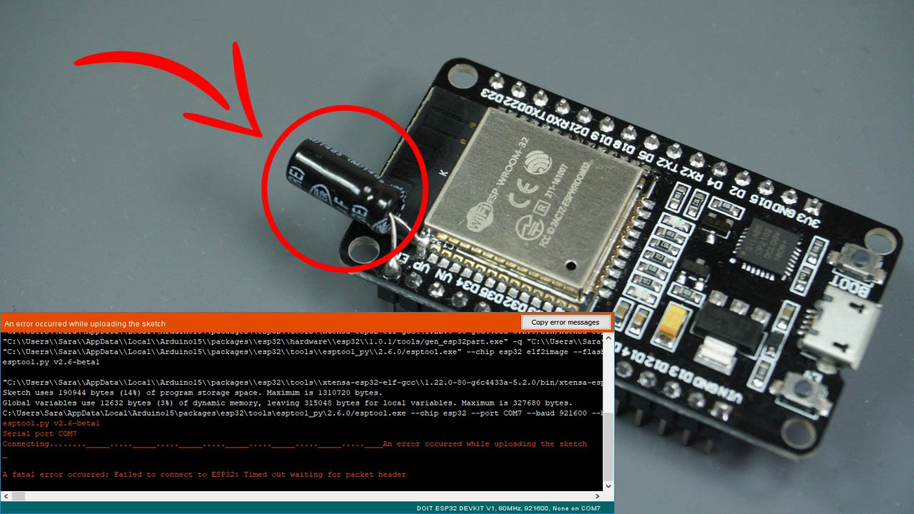
Learn how to fix the Fatal Error Occurred: "Failed to connect to ESP32: Timed out waiting for packet header" error when trying to upload code to your ESP32.
full flame
Hey folks! What would be standard practice for level-shifting amplification from my 3.3V controller into a 5V CV output?
I figure I might as well try to get 2 for 1 by using an op-amp for both level-shifting and amplification; if this is indeed the route to go; should I use a rail-to-rail op-amp with 5v and GND rails; or should I use a non rail-to-rail TL074 with +12V -12V rails? Thoughts anyone?
stuck coral
full flame
Hey folks! What would be standard practice for level-shifting amplification from...
Usually a level shifter changed from one voltage or another for a digital line, what is the purpose of the additional amplification?
full flame
Maybe my terminology is wrong; I need it for an analog line
stuck coral
Well then we just toss the level shifter out the window and just use a op amp
full flame
👍
delicate lava
would it be okay to use a 5v from molex cable and another 5v from sata cable in parallel to power up a led strip? (both cables from a pc PSU)
since the volts are same i think it would be safe to use in parallel as opposed to 2 seperate molex or 2 seperate sata cables' 5Vs in parallel
cedar mountain
I can't say for sure, but that sounds pretty safe if they're coming from the same PSU.
delicate lava
yeah same psu. all red cables have 5V, i suppose which ground I use wont matter since itll be the same psu's ground anyway.
elder hare
dunno if anyone has ever experienced this befor but
i cant give more then this but something weird is going on with my esp32 (rather i think it is my code) im testing as i write this! so what happens is that after some time (unknown at this stage) the ESP32 becomes unresponsive and starts outputting garbage on the serial monitor (and alot of it) it just prints infinite garbage untill i restart it and it is back to normal!
now 2 things im testing is
- just starting it up and leaving it there to see if the same thing happens
- starting it up and actually make a socket connection and leaving it to see if that triggers it (i have had the garbage stuff happen while i was connected via socket and was AFK from the software not sending anything)
elder hare
got it fixed 🙂
pliant totem
So update on my predicament, i was able to find out that i can write to an SD card while simultaneously running two current sensors by disabling the functionality of the display.
I've asked some folks at stack exchange and said that i could try getting a nano every for an increase in ram
however, here's what i dont get
i've made a prototype of a powerlogger in the past using 1 display, 1 sd card reader/writer, and 1 current sensor, and the powerlogger functioned well
how come can't i replicate the same effect with 2 displays, 2 current sensors, and 1 sd card reader/writer?
oh and second, how much ram does the servo library use?
man, if only i have a way to see how much ram im actually using in my nano
cedar mountain
Typically there will be a compiler option to generate a "map file", which will give you the complete memory layout so you can see how much different variables occupy.
stuck coral
Unless they are allocated at runtime
pliant totem
hmm, im currently running avr-size on my code
 stuck coral
bss + data are statically allocated variables unassigned and assigned
pliant totem
according to a site, sram usage is data + bss, which means im using 1252 bytes
stuck coral
But thats at compile time, when are you allocating for those objects, are they making allocations themselves?
If its on the stack or heap it gets a little tougher
Did you try out Ckyiu's code snippet to view heap usage?
pliant totem
hmm i dont know what that is
stuck coral
You can also just watch stack height but that is unlikely to be the issue
stuck coral
pliant totem
hmm i dont know what that is
Which part?
pliant totem
ckyiu code
stuck coral
pliant totem
alright so, im dumb and here's my actual stats from compiling the code

hmm, im in danger
stuck coral
Ooof, variables use 74% of memory
Only have 528 bytes left for variables, use them wisely 😉
stuck coral
Possibly, memory issues can be really hard to fix, and can show themselves in quite strange ways. You could have something else writing in the display buffer, or the library is doing something funky and cant without the memory but keeps going anyways
pliant totem
humm
stuck coral
I would say you are most likely having a memory problem looking at those stats
Remember you also need memory for stack, you might be stack smashing
pliant totem
well, i can sacrifice my displays for sensor readings and sd card writing
but man, what do i write in my final report
stuck coral
Well what is the report supposed to be for? And no way to use a micro with more resources?
pliant totem
stuck coral
Well what is the report supposed to be for? And no way to use a micro with more ...
well, this is for a final project of mine
it's about making a fully fledged solar tracker system
stuck coral
Most arm micros vs avr also have DMA, idk how polished your project will be but that makes writing to one or multiple displays much smoother
pliant totem
to simplify everything, i wired every single function needed to 1 single nano
that includes current reading for actuator usage and power generation (2 INA219 sensors), light sensor readings, displaying data, SD card writing capabilities, and servo control
everything is already cooked
i've already printed the pcb
i just need to code it
turns out, i've overestimated nano's capabilities
so hard
here's my current wirings

i am an inexperienced man
stuck coral
I would say be super clever and construct / destruct your library objects as you need them, but that doesnt work great for displays
Do the displays show the same or different things?
pliant totem
stuck coral
I would say be super clever and construct / destruct your library objects as you...
i dont know how to do that
pliant totem
stuck coral
Do the displays show the same or different things?
different
i was thinking of only using 1 display
but that also didnt work
it hangs
stuck coral
Well I would have tried to make that work before adding a second
pliant totem
man
stuck coral
pliant totem
i dont know how to do that
For your info, this is how we use the heap https://www.tutorialspoint.com/new-and-delete-operator-in-cplusplus
The new operatorThe new operator requests for the memory allocation in heap. If the sufficient memory is available, it initializes the memory to the pointer var ...
But its not good to just allocate and deallocate, causes heap segmentation over time
pliant totem
i guess ill have to write down : "after experimenting, the arduino nano is not able to handle all the functions from the board. So, some functionalities have to be disabled for now"
pliant totem
stuck coral
For your info, this is how we use the heap https://www.tutorialspoint.com/new-an...
how long does it take to perfect? i only got one month
stuck coral
Im not certain what sort of answer you'd like for that, how about this, can you make just a display demo work?
Then lets try putting your SD card library object on the stack
pliant totem
stuck coral
Im not certain what sort of answer you'd like for that, how about this, can you ...
yes, i can make the sensors and the display work while disabling sd card writing capabilities
pliant totem
how do you do this exactly?
im kinda scared of tinkering directly into the libraries themselves
im not experienced in these sorts of things
stuck coral
Wont need to, is it okay to read and write to the SD card only occasionally?
pliant totem
hmm, well
i guess, i can write for every like 100 milis or 1 sec
if so, then i guess adding a delay works?
stuck coral
I was thinking more is it okay to queue your data over time to write if we can find the memory to do so
You dont have a very easy problem, sometimes you can do this easily but display and sd are two of the worst options for what Im talking about
pliant totem
right, i gtg for now, ill ask yall tomorrow
stuck coral
pliant totem
right, i gtg for now, ill ask yall tomorrow
Sounds good, Ill sleep on your issue a tad
 robust iris
Hi, I'm trying to create LED dome. It has to be programable, I would use only one LED at the time. I know I can connect LED in a paralel way but i will make construction bigger and heavier what I would like to avoid. Unfortunately I cannot use already existing ws2811 diodes as they are too weeak or light spectrum isn't as I would like to have. Is there any smart way to create programmable chain of LED of my choice?
stuck coral
robust iris
Hi, I'm trying to create LED dome. It has to be programable, I would use only on...
There are i2c (and I think one wire?) led drivers you could check out, I dont have a part number to really recommend handy
How many LEDs are we talking?
robust iris
@stuck coral
The problem is that my goal is to create prototype so I'm not sure and it has to be easily expandable. First try will be 32 units but it may grow over the time. I will adapt dome (half dome) size and quantity of LED ligths depending of effect
stuck coral
Obviously as you seem to know, the addressable LEDs are the way to go normally, but otherwise Im finding many parts that can do what you need, just not as a nice development board
Could just use a pwm board, let me see
robust iris
Yes that is why I would like to use addressable LED. The problem is the choice of 3-5W is so limited I just can't go with that. I was thinking about building addressable LED units myself but my knowledge is just too little and I don't even know if it is possible
stuck coral
It is, which is the way I was originally thinking but youd need to make PCBs. How many watts do you need? The addressables get quite bright
Here is a better question, what LEDs would you like to use?
robust iris
My starting point is 3w per unit and of course if it wont be enough I would go up. And if it will be enought I will know after first "field" tests. It is photographic aplication so it is almost impossible to calculate without test.
well, I would like for sure use full spectrum cri >95 LED. As well I would like to have some IR but one specific wavelength

aliexpress.com
Achetez malin, vivez mieux! Aliexpress.com
let say something like that 3w version
stuck coral
Do you know where I can find a datasheet for your specific led?
robust iris
well not really. I have chosen this one because of power and CRI value that is acceptable but it can be any LED that will mach criteria. I know only what I have seen on aliexpress
stuck coral
robust iris
well not really. I have chosen this one because of power and CRI value that is a...
I just remembered, what we are talking about is already a product
https://www.stratusleds.com/store/120w-air-module this is specifically for use with drones

StratusLEDs
The Stratus LEDs Air Module is the most powerful LED on the planet for its size and weight.
For photographic and video applicaitons
robust iris
oh it is not a "drone" it is a dome 🙂
robust iris
stuck coral
10x the wattage, clearly 10x better 😉
well I have also power limits as it shouldn't be heavy. What more I cannot use super strong lights as subject of photographying might be sensitive to light
stuck coral
You can buy just the board, and it and other similar boards to drive the LEDs, which wouldnt require using the niche parts I am finding on digikey and making your own PCB
Little pricy though, Ill look for something else https://www.stratusleds.com/store/lumiboost-led-driver
 stuck coral
This would be much easier with a datasheet 😜
robust iris
ok, so what I will do now, I will search for a LED that maches criteria and have some data
stuck coral
That would be best, thank you. That page technically gives enough info for someone to find a driver, but its really not amazing
And having a datasheet, youll have more info about color and other things you care about
Is this running on batteries or the wall?
robust iris
wall
YUJILEDS® BC series high CRI LED SMD
Don't know this company and prices but all their LEDs are >95 RA and they have datasheets. I just don't know how choose power as flux tells me nothing
stuck coral
robust iris
Don't know this company and prices but all their LEDs are >95 RA and they have d...
Look at the intensity chart in the datasheet, should tell you if its bright enough
 copper trout
Heey all! I'm trying to create a project that I can control from a smartphone application. I would like to build a flutter application which controls my board(with wifi). Does anyone know where to start? Thanks in advance!
stuck coral
robust iris
Don't know this company and prices but all their LEDs are >95 RA and they have d...
1.35 Lumens it appears to be? Im not a led expert
stuck coral
copper trout
Heey all! I'm trying to create a project that I can control from a smartphone ap...
Do you need to be able to access it over the internet or just local network? You have many options
robust iris
stuck coral
1.35 Lumens it appears to be? Im not a led expert
1.35 seems to be not very bright. This is why I based on W as I know what to expect more or less.
"A 3-watt LED bulb may produce anywhere between 240 to 320 lumens of illumination."
copper trout
stuck coral
Do you need to be able to access it over the internet or just local network? You...
Id rather use it over internet if thats possible
stuck coral
copper trout
Id rather use it over internet if thats possible
Do you want your own service, or use an existing solution for cloud connectivity?
stuck coral
robust iris
"A 3-watt LED bulb may produce anywhere between 240 to 320 lumens of illuminatio...
How about 10W? Im willing to bet efficiency is down slightly, maybe its linear but I doubt it
Also, in that case we'll need to find another LED
robust iris
stuck coral
How about 10W? Im willing to bet efficiency is down slightly, maybe its linear b...
10 W may be to much. I don't know. From the test I have made 5x 0.3w diode was barely enough so I assumed that 3w would be perfect as starting point.
What I have also seen 10 w are usually COB
stuck coral
This site looks promising https://www.bridgelux.com/. If you want we can use a 3W
Bridging Light and Life™. At Bridgelux, we help companies, industries and people experience the power and possibility of light.
robust iris
and even if it is not a big deal I would like to say with one unit
robust iris
stuck coral
This site looks promising https://www.bridgelux.com/. If you want we can use a 3...
let me chec it
copper trout
stuck coral
Do you want your own service, or use an existing solution for cloud connectivity...
I have not really experience in this topic. I would like to have a cheap solution, but I think I can achieve this with existing solutions as well. And because that seems easier at first sight, I think that would work for me (correct me if I'm wrong of course!)
stuck coral
copper trout
I have not really experience in this topic. I would like to have a cheap solutio...
Not wrong, what sort of device are you connecting up?
copper trout
stuck coral
Not wrong, what sort of device are you connecting up?
It's an ESP32
stuck coral
I meant more the application
Helps me give a recommendation
And is this just for yourself?
copper trout
stuck coral
And is this just for yourself?
Uhm yes
copper trout
stuck coral
I meant more the application
Oh sorry, it's like an application that automates things in my house. So I just need to sent like small amounts of data. (for example, at a selected time a certain motor should start doing something)
stuck coral
copper trout
Oh sorry, it's like an application that automates things in my house. So I just ...
Ah okay, so if you issue a command, you need the ESP to get it right away correct?
I would recommend a MQTT solution of some sort, this can as simple as your phone app connects via MQTT, and so does the ESP32 and they just talk over the broker, or you can make it much more complex
There are managed MQTT services, or you can run one yourself
I think even adafruit.io can help you here
Idk about the details allowing a device to subscribe to another device
One issue would be data consistency though, normally we have services deployed alongside the broker which would resolve issues like that, adafruit.io has some storage and I think you can interact with it over HTTP
stuck coral
robust iris
https://www.bridgelux.com/sites/default/files/resource_media/DS405%20Bridgelux%2...
Well that looks really fun to solder 😆 one moment per usual
stuck coral
copper trout
Oh sorry, it's like an application that automates things in my house. So I just ...
Check this link out if things like adafruit.io wont work https://www.cloudamqp.com/plans.html

RabbitMQ can uses queuing to negate the requirement of other services and there is a free plan
stuck coral
robust iris
https://www.bridgelux.com/sites/default/files/resource_media/DS405%20Bridgelux%2...
Im finding plenty of parts which will work, though a cheap already made product for you to use is being a challenge
Omg I found one https://www.sparkfun.com/products/13716

This is the FemtoBuck, a small-size single-output constant current LED driver. Each FemtoBuck has the capability to dim a single high-power channel of LEDs
copper trout
stuck coral
RabbitMQ can uses queuing to negate the requirement of other services and there ...
Thanks, I will look into this and MQTT
robust iris
soooo I need 32 times this femtobuck and I would be able to connect it in the same way as adressable LED strip ?
Do I understand it right?
stuck coral
Nope, you then need a PWM signal to each driver, running many high power LEDs is super fun
You are right in that youd need 32
This has three channels and would work, but idk if you can control each channel by itself https://www.sparkfun.com/products/13705

The PicoBuck LED Driver is an economical and easy to use driver that will allow you to control and blend three different LEDs on three different channels.
Oh you can, awesome
Then you only need 11
robust iris
well, so creating something as simple as
https://www.adafruit.com/product/4544
Is not that ... simple
Better grab your sunglasses, your sunscreen, and a bucket hat because these NeoPixels feature a 3W RGB LED and are so bright it's like taking a vacation ON THE SUN. Alright maybe ...
stuck coral
robust iris
well, so creating something as simple as
https://www.adafruit.com/product/4544
...
Nope, those have a LED driver on the LED, with a controller to decode the data
Which is why they are so popular
robust iris
I was hoping someone is producing stuff like that where you can just place LED of your choice
stuck coral
Most buck controllers are programmable in some way, just usually its by resistors, Im not finding a solid driver that works over i2c or one wire that works but I have not ventured into aliexpress or ebay
Maybe someone here knows of a board I cant find
Would be really nice for someone to make a board that does exactly what you need, would be quite simple
robust iris
I know it does the job
https://www.adafruit.com/product/1378

Make your own smart LEDs with the same chip that is used in our NeoPixel strip and pixels. This tiny SOIC-8 is fairly easy to solder and can drive a single common-anode RGB LED or three ...
but how to make use from it in practice... well
stuck coral
robust iris
but how to make use from it in practice... well
Only 18mA output you need 240mA
robust iris
oh, so we know alredy why stronger ws2811 LED are so rare
stuck coral
robust iris
oh, so we know alredy why stronger ws2811 LED are so rare
I gotta go, we can pick this up later today if you'd like, I know there is a solution
robust iris
I would love to. It is second full day I spend on this with no effect
In the same time I have choosen and ordered 3d printer and I couldn't find a simple LED diode
robust iris
stuck coral
I gotta go, we can pick this up later today if you'd like, I know there is a sol...
thanks you very much for your effor
 spice plume
Hi, I'm using a tricolor Eink and am trying to get the reddish black color, does anyone know what it is?
stuck coral
spice plume
Hi, I'm using a tricolor Eink and am trying to get the reddish black color, does...
Most e-inks cannot do that, but some can, are you sure yours can?
stuck coral
robust iris
thanks you very much for your effor
Boy your issue is giving me a heck of a time, I think for something to buy today, buying 11 of those sparkfun boards is your best bet, then you need something like a Adafruit Grand Central M4 one issue you will need to resolve is if there are enough IO with a TCC or TC connection for a PWM signal to each
Either the driver isnt enough for that LED, or its expensive, or I cant find a ready for you to buy board with a specific part
There are enough peripherals but there might be something you run into with the pin mux
 quartz furnace
I am opening 4 files from a SD Card. How can I loop this code 4 times and have the "for i" replace all appropriate places
  if (myFile1) {
    Serial.println("test.txt:");
  while(myFile1.available()>0) {
   char SDpassword1 = myFile1.read();

      bufSD1[indexSD1] = SDpassword1;
      indexSD1++;
      }
   }
myFile1.close()```I think I know parts of how to get it done, like "myFile[i].close();"
No clue on how to do ("KEYCODE.TXT");
wraith current
@quartz furnace it's more trouble that is worth to use a for loop there.
Could write a function that returns a string through.
pliant totem
@stuck coral so, about yesterday, what did you suggest me do?
stuck coral
pliant totem
<@!461746819345416203> so, about yesterday, what did you suggest me do?
Was to put the SD constructor in your function calls to place it on the stack then use pointers to interact with other functions, but that doesnt really help the issue unless you free memory somewhere else and will cause another issue. The way we need to fix this is more memory, how about a nano 33?
pliant totem
humm, alright
i guess ill go with the nano every plan
thanks m8s
are yall sure this is a memory problem again?
like i said, i can somehow make every function work using 1 current sensor, 1 oled display, and 1 sd card reader, but it doesnt work when i use 2 sensors, 2 displays
however all of the i2c devices can work if i remove the sd card function, and i could also make the sd writing function work if i remove the functionality of the displays
are you guys sure this is a memory problem?
stuck coral
Nope, but we can say with a reasonable sense of confidence it probably is
pliant totem
hmm, okay
robust iris
Thanks. I see it will be bigger issue I supposed. I think I will go with neopixels and then make extensive tests trying at the same time to figure out how to solve the problem with custom LED. Maybe I should try to contact manufacturers to prepare custom boards for me. I just doubt in programming ease of this kind of solution. Anyway. Thank you
robust iris
robust iris
Thanks. I see it will be bigger issue I supposed. I think I will go with neopixe...
@stuck coral
stuck coral
robust iris
Thanks. I see it will be bigger issue I supposed. I think I will go with neopixe...
I doubt a manufacturer would make you a board, but you can get help here in the future if you dont find another board #help-with-hw-design
rough torrent
Hmmmmmmmmm I'm trying to use an Adafruit 2.8 resistive touch screen with an ESP32 and I've got the drawing code on it working quite nicely 🙂
The only problem is that whenever I press down on the touchscreen that the pressure becomes negative 😦
Any thoughts?
(I've checked the wiring multiple times but I have not calibrated it - I don't know how to)
crisp folio
Are you using a signed instead of an unsigned int
pliant totem
guys, question, how long does it take for arduino i2c displays to display stuff?
robust iris
stuck coral
I doubt a manufacturer would make you a board, but you can get help here in the ...
thanks, surely I will be back to this subject soon.
pine bramble
@pliant totem Some of the old literature said SPI was faster for writing to displays, iirc.
Hobby displays were meant for at all use cases not for performance cases.
(I have a display that 'kind of works nice' versus 'I have a display that doesn't work at all'.)
They're bridging the other gap ('I have a display that performs minimally' vs ('I have a blazing fast display - wow!')
pliant totem
Dang it
pine bramble
I'm seeing SPI for most of the Adafruit TFT's. Just glancing at them.
ISTR at least one supported i2c but I don't see it.
Sorry that one's 8 bit or SPI - the touch is i2c or SPI.
SPI is slower than 8-bit mode. Forget what I said about i2c - it was 8-bit I was comparing SPI to.
Now I'm thinking I've not seen an i2c display at all. ;) /long time
 errant cradle
So, I have an Arduino Uno that I want to use as a peripheral (I specifically want to make myself a keypad for osu!catch), but I can't get the computer to see it as a keyboard (or anything apart from a serial port, for that matter)
Is it just not possible to use it as a USB gadget?
 surreal pawn
errant cradle
So, I have an Arduino Uno that I want to use as a peripheral (I specifically wan...
surreal pawn
errant cradle
So, I have an Arduino Uno that I want to use as a peripheral (I specifically wan...
on the Uno you'd have to reprogram the chip used for serial conversion to act as something else. It's a lot easier to use an feather m0, teensy, leonardo or something that does native USB as a keyboard instead
errant cradle
Unfortunately, I don't have any of those
I only have an Arduino Uno and a Raspberry Pi 4
surreal pawn
do you have an AVR programmer?
errant cradle
No
surreal pawn
here's instructions I found
https://www.instructables.com/How-to-Make-a-Arduino-HID-Keyboard/

Instructables
How to Make a Arduino HID Keyboard: Controller by picklesandicecreamIn this tutorial I shall explain how you can turn your Arduino chip into a HID keyboard device. This is done by updating the Firmware on your chip with FLIP.The cool thing about this trick is that you can make your ow…
surreal pawn
if you have an aftermarket uno that doesn't have that 6 pin thing in that corner then you won't be able to make that work
errant cradle
The ICSP header?
surreal pawn
the second ICSP header near pin 13
errant cradle
yeah, it has it
spice plume
stuck coral
Most e-inks cannot do that, but some can, are you sure yours can?
I'm not sure. I saw the 2.9" could, and just assumed the 2.13" could too.
heavy star
Partial update capabilities are unrelated to an eInk display's size
stuck coral
heavy star
Partial update capabilities are unrelated to an eInk display's size
No but it is the specific panel used which is typically quite different between sizes
surreal pawn
Has someone already written something to dump all device registers to serial or serial USB? (samd21)
I'd like to see what peripherals are getting enabled and configured that I'm not un-configuring fully. Then soon I'll be working towards running on batteries
stuck coral
surreal pawn
Has someone already written something to dump all device registers to serial or ...
I remember someone doing this, if i remember right it was a library but I cant find anything with a quick duckduckgo search
stuck coral
surreal pawn
Has someone already written something to dump all device registers to serial or ...
GitHub
print out the low-level configuration registers for the Arduino Zero (and similar boards) - drewfish/arduino-ZeroRegs
Aha! found it
surreal pawn
thanks I'll look into that
 tepid flicker
Hey, I’m trying to make a circuit that with the use of a photoresistor,potentiometer, and a relay. This needs to switch between two leds.
 twilit hare
has anyone tried to get touchInterrupts working with Arudino on ESP32-S2? Works fine with a ESP32... but doesn't seem to work with an S2.
 glad birch
I remember reading about that on some reddit post, the S2 if I recall correctly and im unsure if the standard S did as well does have some features that don't run the same way.... ill look it up one minute
glad birch
twilit hare
has anyone tried to get touchInterrupts working with Arudino on ESP32-S2? Works ...

ESP32 External Interrupts Examples & Tutorial in Arduino IDE. ESP32 GPIO Interrupts Examples, ESP32 Interrupt Latency and response time
I am really tired and not finding anything unique to the 32s
but I do see a lot of documentation that indicates the need to handle interupts differently
twilit hare
@glad birch - don't worry about it... I spent about an hour trying to find something, and came up with nothing (easy) as well. I did take a peek at the Circuit Python documentation for touchio for ESP32s2... I'm sure there's something there I can use to write an arduino example... maybe that'll be a project for next weekend
glad birch
yeah, but.... I do remember hearing about this before and there was a very specific reason for it.
I think its one of the more obscure issues brought up though, but the 32 S had some compatibility issues with arduino libs for a few reasons I am sure others here are better suited to explain
if someone who knows sees this, please ping me the answer cuz I forgot and I know I just ordered a few more of these and id rather remember, I think it was due to the inclusion of additional memory types
 warm beacon
I'm using an ADXL3xx sensor right now for getting acceleration data, my problem is though that it measures in "g"s
I want that acceleration to be in m/s^2 and I tried just multiplying every value by 9.8 to try and cancel out the g but that gives weird values
How can I get my measurements in units of m/s^2?
 stable forge
warm beacon
I want that acceleration to be in m/s^2 and I tried just multiplying every value...
stable forge
warm beacon
I want that acceleration to be in m/s^2 and I tried just multiplying every value...
(EDIT) The CircuitPython library returns m/s^2 using this calculation
 @property
    def acceleration(self):
        """The x, y, z acceleration values returned in a 3-tuple in :math:`m / s ^ 2`"""
        x, y, z = unpack("<hhh", self._read_register(_REG_DATAX0, 6))
        x = x * _ADXL345_MG2G_MULTIPLIER * _STANDARD_GRAVITY
        y = y * _ADXL345_MG2G_MULTIPLIER * _STANDARD_GRAVITY
        z = z * _ADXL345_MG2G_MULTIPLIER * _STANDARD_GRAVITY
        return (x, y, z)
but you can specify the range as 2G, 4G, etc. so you can use a lower range when you need more accuracy and you know the upper limit
ah sorry, this is the arudino library? You can adapt code like the above. constants above are:
# Conversion factors
_ADXL345_MG2G_MULTIPLIER = 0.004  # 4mg per lsb
_STANDARD_GRAVITY = 9.80665  # earth standard gravity
note the multiplication by 9.8 and the 0.004 multiplier
warm beacon
stable forge
note the multiplication by 9.8 _and_ the 0.004 multiplier
Ah ok, so if I understand correctly, I need to multiply my g values by 9.8 and 0.004?
rough torrent
Well, depends on whether you are on Earth or not 😉 /j
stable forge
warm beacon
Ah ok, so if I understand correctly, I need to multiply my g values by 9.8 and 0...
apparently so, try that and see if the results look reasonable
warm beacon
`int xpin = A3;
int ypin = A2;
int zpin = A1;
int xvalue;
int yvalue;
int zvalue;
void setup()
{
Serial.begin(9600);
// initialize the serial communications:
}
void loop()
{
xvalue = analogRead(xpin);
//reads values from x-pin & measures acceleration in X direction; baseline values acquired from sensor calibration
int x = map(xvalue, 260, 392, -100, 100);
//maps the extreme ends analog values from -100 to 100;
float xg = ((float)x/(-100.00)) * 9.8 * 0.004;
//converts the mapped value into acceleration in terms of "g"
Serial.print(xg);
//prints value of acceleration in X direction
// Serial.print("g ");
//prints final calculated acceleration values, updated every 1/10 of a second (timing can be changed)
yvalue = analogRead(ypin);
int y = map(yvalue, 259, 392, -100, 100);
float yg = (float)y/(-100.00);
Serial.print("\t");
Serial.print(yg);
Serial.print("g ");
zvalue = analogRead(zpin);
int z = map(zvalue, 266, 399, -100, 100);
float zg = (float)z/(100.00);
Serial.print("\t");
Serial.print(zg);
Serial.println("g ");
delay(100);
}`
that's the code i wrote, i just took the line that was giving me my g value for x, and put brackets around it and multiplied by 9.8*0.004
@stable forge
when the sensor is at rest, my x acceleration according to the serial monitor and the above code is 0.04, and when I start moving it, it jumps to around 0.09 which idt is correct, as 0.09 m/s^2 would be too slow
stable forge
The ADXL345 outputs digital x,y,z accelerometer info, but you are doing analog reads -- I'm confused. Have you tried our Arduino library? https://github.com/adafruit/Adafruit_ADXL345
what sensor are you using?
warm beacon
stable forge
what sensor are you using?
im using the ADXL335
stable forge
OH, then I'm no help here, other than to say I would study the datasheet. The multiplication I recommended is not applicable at all, I assume
warm beacon
ok, thanks for your help tho
rough torrent
Does anyone know on how to diagnose a non-working touch screen? I'm using an Adafruit 2.8in touchscreen breakout I bought from Microcenter and I'm getting basically no readings whatsoever even with the simplest code:
// Touch screen library with X Y and Z (pressure) readings as well
// as oversampling to avoid 'bouncing'
// This demo code returns raw readings, public domain

#include "TouchScreen.h"

// These are the four touchscreen analog pins
#define YP A7  // must be an analog pin, use "An" notation!
#define XP A6  // can be any digital pin
#define YM A3  // can be any digital pin
#define XM A0  // must be an analog pin, use "An" notation!

// For better pressure precision, we need to know the resistance
// between X+ and X- Use any multimeter to read it
// For the one we're using, its 300 ohms across the X plate
TouchScreen ts = TouchScreen(XP, YP, XM, YM, 125);

void setup(void) {
  Serial.begin(9600);
  analogReadResolution(10);
}

void loop(void) {
  // a point object holds x y and z coordinates
  TSPoint p = ts.getPoint();

  // we have some minimum pressure we consider 'valid'
  // pressure of 0 means no pressing!
  if (p.z > ts.pressureThreshhold) {
     Serial.print("X = "); Serial.print(p.x);
     Serial.print("\tY = "); Serial.print(p.y);
     Serial.print("\tPressure = "); Serial.println(p.z);
  }

  delay(100);
}
No readings 😦
I'm on an ESP32, which is why I had to set the read resolution to 10 bits. Sadly, it did not fix it :/
I've also updated the library. Nothing still. Any ideas?
And whenever I do get a reading (when I'm pressing down if I'm lucky) it's some stupid X and Y coordinate:
14:34:19.442 -> X = 1023    Y = 1019    Pressure = 31
14:34:22.664 -> X = 1023    Y = 1021    Pressure = 41
14:34:23.039 -> X = 1021    Y = 1021    Pressure = 24
14:34:23.133 -> X = 1021    Y = 1019    Pressure = 24
14:34:23.272 -> X = 1020    Y = 1018    Pressure = 20
14:34:24.343 -> X = 1022    Y = 1020    Pressure = 748
14:34:24.946 -> X = 1017    Y = 1016    Pressure = 13
14:34:25.974 -> X = 1022    Y = 1019    Pressure = 24
14:34:37.973 -> X = 824    Y = 861    Pressure = 27
14:34:38.958 -> X = 921    Y = 976    Pressure = 130
14:34:39.051 -> X = 991    Y = 1021    Pressure = 1411
14:34:40.173 -> X = 984    Y = 1005    Pressure = 148
(the screen is only 320x240)

^ wiring (the pieces of paper are so the my phone camera doesn't dim everything because of how bright it is)

^ definitely not standard compliant schematic of what i think should be happening
leaden ruin
Don't know about the Arduino library, but in CPy I have to scale the touchscreen coordinates to match the screen resolution.
rough torrent
OH yea that's true thanks for reminding me 🙂
Now time to do some calibration...
Top left:
14:52:16.252 -> X = 1019    Y = 1019    Pressure = 41
14:52:16.438 -> X = 1003    Y = 1002    Pressure = 30
14:52:24.168 -> X = 1001    Y = 1001    Pressure = 226
14:52:25.653 -> X = 1013    Y = 1012    Pressure = 27
14:52:28.770 -> X = 1003    Y = 1004    Pressure = 153
14:52:30.969 -> X = 998    Y = 1002    Pressure = 30
14:52:32.042 -> X = 998    Y = 997    Pressure = 18
14:52:32.133 -> X = 999    Y = 1000    Pressure = 33
14:52:33.859 -> X = 995    Y = 996    Pressure = 26
14:52:38.939 -> X = 986    Y = 986    Pressure = 43
Top right:
14:54:08.740 -> X = 874    Y = 949    Pressure = 114
14:54:10.525 -> X = 517    Y = 626    Pressure = 17
14:54:10.665 -> X = 821    Y = 955    Pressure = 134
14:54:11.134 -> X = 1023    Y = 1021    Pressure = 93
14:54:12.256 -> X = 1023    Y = 1023    Pressure = 41
14:54:13.339 -> X = 997    Y = 994    Pressure = 24
14:54:14.040 -> X = 908    Y = 923    Pressure = 11
14:54:14.558 -> X = 744    Y = 876    Pressure = 68
14:54:15.457 -> X = 1023    Y = 1023    Pressure = 374
14:54:15.550 -> X = 620    Y = 709    Pressure = 21
14:54:15.644 -> X = 871    Y = 982    Pressure = 234
14:54:16.157 -> X = 771    Y = 867    Pressure = 57
14:54:16.250 -> X = 927    Y = 1010    Pressure = 594
Bottom left:
14:54:42.436 -> X = 1023    Y = 1023    Pressure = 62
14:54:42.622 -> X = 980    Y = 970    Pressure = 34
14:54:44.529 -> X = 1022    Y = 1022    Pressure = 41
14:54:47.425 -> X = 822    Y = 843    Pressure = 14
14:54:47.564 -> X = 970    Y = 1003    Pressure = 175
14:54:47.936 -> X = 949    Y = 945    Pressure = 24
14:54:48.728 -> X = 955    Y = 950    Pressure = 11
14:54:51.758 -> X = 957    Y = 955    Pressure = 15
Bottom right:
14:55:15.028 -> X = 1018    Y = 1016    Pressure = 173
14:55:15.264 -> X = 973    Y = 971    Pressure = 55
14:55:15.544 -> X = 681    Y = 757    Pressure = 23
14:55:16.330 -> X = 882    Y = 955    Pressure = 113
14:55:16.936 -> X = 975    Y = 987    Pressure = 42
14:55:19.356 -> X = 795    Y = 879    Pressure = 55
14:55:19.823 -> X = 728    Y = 873    Pressure = 81
14:55:20.340 -> X = 688    Y = 788    Pressure = 34
14:55:20.434 -> X = 883    Y = 981    Pressure = 215
Although I have to touch pretty hard for it to do something, and only occasionally it will print something out.
I guess I just need to filter out the 1023, 1023 and just map the rest?
leaden ruin
Use a fingernail or a stylus, the resistive touchscreens don't handle fingertips very well.
pine bramble
I like the stylus input method - Palm III used it.
 shy jetty
Hey all, I'm using these libraries for my 128x64 oled:
#include <Adafruit_GFX.h>
#include <Adafruit_SSD1306.h>
#include <Adafruit_I2CDevice.h>```
Now, I'm making a PCB on which I can test multiple modules. So I'm using a lot of libraries. The problem is that I'm using too much ram.
Since the oled itself takes up nearly half of the ram on the arduino, is there a good way to clear up some of that ram usage by disabling some parts of the screen? for example, to skip the first 7 lines, and the last 7 lines of pixels?Any other way to clear up ram would be appreciated as well :)
rough torrent
Alright progress update wired up an un-used uno to it and it works perfectly fine
So there must be something going on weird with the ESP32
 umbral basalt
Hi guys, using the Adafruit 52840 Express as a Peripheral and BLE Connect App as Central.... How would you convert the input of numbers (say 1, 2, or 3) coming from BLEUART Connect App to a variable in the code that can be used for multiplication. For reference the bluetooth section of the code is
https://learn.adafruit.com/bluefruit-nrf52-feather-learning-guide/bleuart
{
// Forward data from HW Serial to BLEUART
while (Serial.available())
{
// Delay to wait for enough input, since we have a limited transmission buffer
delay(2);
uint8_t buf[64];
int count = Serial.readBytes(buf, sizeof(buf));
bleuart.write( buf, count );
}
// Forward from BLEUART to HW Serial
while ( bleuart.available() )
{
uint8_t ch;
ch = (uint8_t) bleuart.read();
Serial.write(ch);
}
}

Adafruit Learning System
Get started now with our most powerful Bluefruit board yet!
rough torrent
well ch is a char, you can just keep reading into a buffer and once you get a non-number char, you can use atoi or atol (standard C functions - search it up)
rough torrent
rough torrent
So there must be something going on weird with the ESP32
I've posted more information in this Forum thread if anyone is wondering:
https://forums.adafruit.com/viewtopic.php?f=47&t=179912
I'm guessing the Adafruit_Touchscreen library needs a rework to support the ESP32 but that's just my guess 🙂
pliant totem
Guys, is there a way to separate 2 processes at once in arduino?
so that it can run simultaneously?
cedar mountain
There's different types of "simultaneously". The simplest approach is to have two fast-running functions called repeatedly in loop(), checking the values of millis() whenever they need to wait on something.
One step up from that is to have one or both of them running from a timer interrupt instead of the main loop.
Beyond that you start to get into RTOS territory.
But most chips cannot strictly run multiple things at the same time, so it's just a matter of switching between the processes quick enough so you don't notice.
 sharp turret
in most cases, you don't need threads for multiple "processes." as said, millis() based state machines can handle a lot of "multitasking" without the overhead of an operating system
e.g., I have lots of code that does multiple things: blinks LEDs, checks serial for commands, and updates a display without "threads" or interrupts. I just use millis() to see when it is time for each to do the next "thing"
but if your code is written like: "blink, delay, blink" and "check button, delay, process button" you have to re-think your logic
pliant totem
hmmm
well, my current code currently has a logic to display a data with an OLED and then update the position of a servo
so something like :
display data - update pos - display data - update pos
apparently, the time it takes to display data with an i2c OLED device is pretty long, so it caused massive stuttering issues on the servos
so, is there any way to circumvent this?
cedar mountain
Can you split up the OLED I2C transactions, like write one pixel line on the display between servo updates?
pliant totem
isn't that the logic that's already there?
basically my code is like this :
  ina219valuesA();
  ina219valuesB();
  getsensor();
  getpos();
  displaypower();
where get sensor and ina219values takes a value from sensors, getpos updates the servo position according to getsensor, and display power displays the power from ina219values
for display power :
void displaypower()
{
  display1.clearDisplay();
  display1.setTextColor(WHITE);
  display1.setTextSize(1);
  display1.setCursor(0, 0);
  display1.println(energyA);
  display1.display();

  display2.clearDisplay();
  display2.setTextColor(WHITE);
  display2.setTextSize(1);
  display2.setCursor(0 ,0);
  display2.println(energyB);
  display2.display();
}
for getsensor :
void getsensor()
{
  BR = analogRead(A0);
  BL = analogRead(A1);
  TR = analogRead(A2);
  TL = analogRead(A3);
  R = BR + TR;
  L = BL + TL;
  T = TR + TL;
  B = BR + BL;
  difTB = T - B;
  difRL = R - L;
}
for getpos :
void getpos()
{
  if (difTB > 800)
  {
    posP = posP + 1;
    if (posP > 140)
    {
      posP = 140;
    }
    myservoP.write(posP);
    delay(5);
  }
  else if (difTB < -800)
  {
    posP = posP - 1;
    if (posP < 60)
    {
      posP = 60;
    }
    myservoP.write(posP);
    delay(5);
  }


  if (difRL > 800)
  {
    posB = posB + 1;
    if (posB > 170)
    {
      posB = 170;
    }
    myservoB.write(posB);
    delay(10);
  }
  else if (difRL < -800)
  {
    posB = posB - 1;
    if (posB < 30)
    {
      posB = 30;
    }
    myservoB.write(posB);
    delay(10);
  }
}
does anyone know why the heavy stuttering?
the stuttering stops when i dont include displaypower();
pliant totem
oh and another question, does anyone know why sometimes servo spasms and randomly halts the entire arduino process?
pliant totem
alright guys, does anyone know why sometimes my arduino would just halt?
and then it wont work when it uses a battery as a power source?
this will always happen when im messing with my servos and i dont know what's wrong with it
pliant totem
Guys, emergency, suddenly all of my circuit board can't be powered by an external power source, meanwhile, using a micro usb works
is it because of the connector? i have been using jumper male and female connectors, but when i tried it earlier, it worked, now it doesnt, does anyone have any clue what's going on here?
all of my components are working as intended, nothing is broken
it's just that when using a buck converter, nothing wants to work, my arduino just flashed momentarily and then it doesn't work
the led on it just dimly lit
it's like it's entering a safe mode or something, does anyone know what's going on? i need help ASAP
north stream
Your servo spasm and halts point to a power problem of some sort
I'm not sure which Arduino you're using, but some of them have steering diodes from the USB power and external power pins: if your external power pin stopped working, it could be one of the steering diodes died.
It could also be a jumper wire failed (it happens), it's worth trying fresh ones (for both power and ground from your external power)
north stream
I'd grab a multimeter and start measuring
There are a bunch of things that could be happening, so some measurements are a quick way to narrow down the possibilities.
pliant totem
Right, it might be that problem
Thank you
Ive tried powering my arduino with a 5 volt power source alone and it went dim
So yeah, i think the diode went kapoot
north stream
It's an unusual failure mode (diodes usually fail shorted), but not impossible.
pliant totem
Humm, any ways i can fix this?
Or do i have to buy another one?
Other than changing the diode
And are there any things i can do to prevent these sorts of shortages in the future with servos?
I swear servos are a bane to me
north stream
It depends on the board you have and your situation. Sometimes you can feed power into the Vusb pin, but you have to make sure you don't do so when USB is connected.
Servos (and other inductive loads) cause voltage spikes and sags. I like to run them from a separate supply from my logic circuitry.
If I can't run them from a fully separate supply, I use supply isolation and filtering to limit their effects on my other circuitry.
pliant totem
humm, that's the thing, i am running my servos from a different supply

at the bottom left, there are servo base and servo pivot pins where their power is connected to a separate buck converter from the one that is used to power the electronics
then what is it that caused my diode to short?
well, i did short my power supply, could that be it as well?
man, i knew i should've put the pins further
north stream
It could be that: generally I'm unable to trace a failure to a specific cause. Sometimes it's obvious, usually it's "it could have been one of several things, or just a random nuisance failure"
north stream
I normally run servos with PWM, so the CPU doesn't really get involved except when changing the setting. So the hiccups happen when the CPU gets interrupted while updating the PWM registers, or if the timer the PWM is using gets changed by something else, if something interferes with the signal, or if something interferes with the power supply.
Arduino halts can come from a bunch of causes. The ones I see most often are running out of memory, followed by running amuck, and power supply glitches. But there are a bewildering variety of less common possibilities that still happen occasionally.
pliant totem
is running servos with pwms the same as running it with the my servo library?
pliant totem
@north stream ?
north stream
Heh, that's another one of those "it depends" kinds of questions. Most servo libraries will use PWM if the servos are configured on pins with PWM support. It can get complicated when multiple servos (or other functionality) shares the same timer.
pliant totem
i see
elder hare
im currently using WS2812B ❤️ love them! but what options do i have for addressable led (like WS2812B with RGB) but also with pure white like RGBW?
 gilded swift
Sk6812
elder hare
@gilded swift i'll look it up thanks 🙂 btw im using FastLED lib, do you know if that lib is smart in using the white LED when calling for white or is it just "ON or OFF" kinda thing?
 gloomy karma
Hello, I put a micro switch on my Adruino and at first my arduino wasn't reading my port so I had deleted my driver. But now something weird happend:
Is there something wrong with my cable?
gilded swift
elder hare
<@!728676724522352733> i'll look it up thanks 🙂 btw im using FastLED lib, do yo...
I think it should be fine with fast LED. You could get a strip with RGBW LEDs and see how they perform
crisp folio
Looks like FastLED doesn't support RGBW https://github.com/FastLED/FastLED/issues/579

GitHub
Nowadays 4 chips ( Red, Green, Blue, White) LEDs are becoming so popular in lighting applications that RGBW leds support is a must. RGB leds are unable to light up your room with warm, nice looking...
gilded swift
That’s a bummer
 sturdy bobcat
There are some escoeteric hacks you can make it work, but you might want to try NeoPixelBus instead.
gilded swift
The regular neopixel does, I’ve not used FastLED as much as the standard neopixe library
sturdy bobcat
Or the Adafruit NeoPixel library.
gilded swift
Yeah
sturdy bobcat
FastLED has a bunch of really good stuff for color management and animation.
So you can kinda use FastLED's calculation code, which is really really nice, and then you can use Adafruit NeoPixel or NeoPixelBus to do at least some of it
glad birch
oh wait
I remember finding something for a workaround when I was using a esp32 and ran into fastled not supporting it
one sec

GitHub
An Arduino NeoPixel support library supporting a large variety of individually addressable LEDs. Please refer to the Wiki for more details. Please use the gitter channel to ask questions as the G...
this supports rgbw as well
oh you guys found it XD, can confirm though this works on all my esp boards, only problem I have is color accuracy but I am sure its a me thing
pliant totem
guys, so im using a stepper motor with I2C displays and using it them for a moment just makes the oled displays go haywire (it displayed white noise/gibberish) and the arduino crash, does anyone know why?
cedar mountain
Possibly your power supply isn't strong enough for the motor, so it's browning out the voltage to the Arduino. The other option is some back-EMF from the motor coils, though that would be unusual if you're using a stepper driver board.
cedar mountain
Depends on the actual problem. What kind of power supply are you using, and what's the stall current for your stepper?
pliant totem
im using a liPo battery and i dont know the stall current, how do i measure it?
cedar mountain
It would usually be given on the datasheet, or you could infer it from the coil resistance and the driving voltage.
 hollow condor
Hey i need some help with code! I'm using a PCA9685 with an Arduino Pro Micro, I want to drive my solnoids (push pull) in a particular sequence and i'm not sure how i can code that, this is as far as i've come, I'm trying to figure out how i can output a push-pull on just pin "0" of the pca, and ill adjust the sequence using delay for other pins.
`#include <Adafruit_PWMServoDriver.h>
/****** configuration /
const int solnoidcount = 4; //
/*************/
Adafruit_PWMServoDriver pwm = Adafruit_PWMServoDriver(0x40 /default/);
long solnoids[solnoidcount] = {0};
void setup() {
Serial.begin(115200);
//initialize PWM board
pwm.begin();
pwm.setPWMFreq(1000);
//Wire.setClock(400000);
}
void loop() {
pwm.setPWM ( 0 , 4095, 0);
delay(1);
pwm.setPWM ( 0, 0, 4096);
}`
the way I've set the pwm doesn't work for me right now, would appreciate some guidance pls
surreal pawn
what if it does work and you don't notice because of your 1ms delay()?
(if you want a 1s delay you should also add one after the 3rd line of loop())
north stream
I'm not sure what you're asking: the PCA9685 can only provide a logic output (it can't drive a solenoid directly). The push-pull capability is determined by your solenoid drivers and the solenoids themselves. Some push-pull solenoids (like the ones that operate door locks in cars) have separate coils for "push" and "pull", each coil would need its own driver. However, many push-pull solenoids (including the ones sold by AdaFruit) use the electromagnet for one direction, and a return spring for the other, so you just activate it for one direction, and deactivate it for the other.
hollow condor
north stream
I'm not sure what you're asking: the PCA9685 can only provide a logic output (i...
I seee so what parameters do I use on the pwm board to output a digital signal that my driver recognises to actuate the solenoid?
north stream
Normally I wouldn't expect to use PWM to control a solenoid, solenoids are normally either "on" or "off".
However, most drivers would accept an ordinary digital signal like the PCA9685 provides
hollow condor
I'll use a video hold on!
north stream
Off to work, I'll try to check in later
hollow condor
Sure whenever you can. I'll just leave it here!
hollow condor
You can see how the output oscillates, So basically what I want to achieve with the code is that it outputs at it's 100%
elder hare
so in the adafruit uber guide for neopixels they say to use a 470 Ohm resistor closest to the first LED in the strip! as i have been a dumdum and put that resistor on the pcb and all my of strips were flickering like crazy! could this be the reason? (im asking now cause i tried just soldering the wires directly to the ESP32 legs and now it's stabel and not flickering at all!! i want to know the reason!
just FYI i run each strip with data wire alone on right side and then i run + and - on the left side of the strip so there is no interferens there!
north stream
@hollow condor This pages describes how to set an output fully on: https://learn.adafruit.com/16-channel-pwm-servo-driver/library-reference

Adafruit Learning System
Learn how to connect and program the 16-channel 12-bit PWM/Servo Driver with Arduino, Python or CircuitPython
It's under the "Using as GPIO" section, and gives pwm.setPWM(pin, 4096, 0);
@elder hare I can't tell you the reason because I don't know. There are a bunch of possibilities, and testing them all would require some time, ingenuity, and test equipment.
hollow condor
north stream
It's under the "Using as GPIO" section, and gives ```pwm.setPWM(pin, 4096, 0);``...
Will check it out, thank you
hollow condor
I did check this out prior, used the values again, I'm still seeing the same thing
I'll update as I figure this out, thanks for the help
north stream
Hmm, I wonder if there's some additional effect confusing things
 wintry wadi
Do you guys have any nice tutorials to set up an arduino with circuit python? I am positive I initialized it properly, but I would like a comprehsnive tutorial about how libraries work and what not(and how to use them, is it through ide?). I'm sorry if the question is to open ended. It's just my school gave me a bad board whose i2c malfunctions 😭 So I bought a new board and im going to try to make a quick little project with this new board
hollow condor
north stream
Hmm, I wonder if there's some additional effect confusing things
Might be! Leaving the output on for a whole second gets it all the way to 12v, when it's short impulses it ascends that way. This is when the solnoid isn't drawing from it. It's much lesser when the solnoid is connected. That being said an obvious way to try would be to use an adaptor with higher voltage to check how it behaves.
north stream
Or higher current, or possibly a different solenoid driver.
A plain (AVR based) Arduino does not have the capability to run CircuitPython, but some of the variants with upgraded CPUs can do so.
hollow condor
I'm using a 12v adaptor now, I don't have something bigger but I do have a soundcard that outputs 48v to power a microphone, I'll try to use that as my power source to test. A different solenoid driver would be hard to source now because of covid
north stream
I doubt the microphone power will be suitable and you could easily damage your 48V supply that way, I wouldn't advise trying that.
hollow condor
Also interestingly, the answer is within the code because I used another one that I found on GitHub and it drove the solnoid, I'll link it here
hollow condor
north stream
I doubt the microphone power will be suitable and you could easily damage your 4...
Noted
It works fine with this, but it uses an audio software as a control surface, I want the control surface to be Arduino ide
`#include <Adafruit_PWMServoDriver.h>
/****** configuration /
const int solnoidcount = 4; //
/*************/
Adafruit_PWMServoDriver pwm = Adafruit_PWMServoDriver(0x40 /default/);
long solnoids[solnoidcount] = {0};
void setup() {
Serial.begin(115200);
//initialize PWM board
pwm.begin();
pwm.setPWMFreq(1000);
//Wire.setClock(400000);
}
void loop() {
pwm.setPWM ( 0 , 4095, 0);
delay(1);
pwm.setPWM ( 0, 0, 4096);
}`
vivid rock
@wintry wadithere is this page: https://learn.adafruit.com/welcome-to-circuitpython
if there are some questions it doesn't answer, you can ask in #help-with-circuitpython channel
north stream
That 1 millisecond delay won't do much for you
Maybe try something like ```arduino
void loop() {
pwm.setPWM ( 0 , 4095, 0);
delay(500);
pwm.setPWM ( 0, 0, 4096);
delay(500);
}
Thank you!
hollow condor
north stream
Maybe try something like ```arduino
void loop() {
pwm.setPWM ( 0 , 4095, 0);
...
Oh I'm sry i changed it
That's still quite low
 gloomy sandal
HI, i want to rotate an model in Autodesk Inventor. For that i want to use an Arduino Leonardo and a homemade Joystick. The code is a modified version of a simple mouse-countolle with joystick code. But it doesnt work. Can someone help me? (I send the code as an zip so that the chat here keeps clean)
my Test code
to rotate an objekt i press left_shift+middel_mouse+mve mouse
my projekt is a bit like this one, but the code also doesnt work https://www.instructables.com/Space-Mouse-With-Arduino-Micro-Fully-Printable/

Instructables
Space Mouse With Arduino Micro UPDATE: Hello Makers!I love 3D cad design and one of the most common panel I use while designing is...View.I often need to spin the object around, zoom in and out, slice it and so on.There are amazing professional 3D mice you can buy, but they are not cheap…
yea i know that one but the code doesnt work
rough torrent
btw just saying it's easier to paste your code directly into discord like this:
```arduino <-- the "arduino" keyword tells discord to syntax highligh
// my code here
```
turns into:
// my code here
because it's kinda annoying to unzip a file and open it instead of just reading it on discord 🙂 plus some people may not be able to download/unzip/open files or they are one a phone
gloomy sandal
oh ok thx i will try that
glad birch
it also works with most other programming languages, just remember to hit enter after stating the language, and on all discord servers
rough torrent
(ex. "python")
gloomy sandal
my code is too long
rough torrent
also you mention that you are using a homemade joystick - does that mean you pieced together some pots and wired them up? are you sure that the joystick actually works?
glad birch
gloomy sandal
my code is too long
pastebin and github
people don't like downloading files like this normally as its a risk, but don't stress, just keep it in mind is all.
gloomy sandal
yes, i bought 5 joystick for ps4 on amazone and made a pcb. i chekt everything and there are no shortcuts oder anything else. wanne see?
rough torrent
yes pls post wiring 🙂
gloomy sandal

 rough torrent
I've uploaded to textuploader.com for you 🙂
http://txt.do/tsvxg
Also hope you don't mind that I formatted some stuff and removed all the "extra" comments and spaces which made it hard to read
textuploader.com - Untitled Post
#include
#include
int horzPin = A1; // Analog output of horizontal joystick pin...
gloomy sandal
2 potis which get connected to GND and VCC und the middle pin is where the Arduino gets his data from by using an Analoge pin. the button is connected to GND when presst, so i gets declerated as HIGH in the Code und if (Button == LOW) the function starts
 glad birch
did you prototype with a breadboard and if so did that work properly?
gloomy sandal
rough torrent
I've uploaded to textuploader.com for you 🙂
http://txt.do/tsvxg
Also hope you d...
thats great thx
gloomy sandal
glad birch
did you prototype with a breadboard and if so did that work properly?
yes everything works fine. I can controlle the mouse with my joystick thats no problem. but my code isnt wokring
north stream
Is the problem getting it recognized as an HID device, sending keystrokes, or having the keystrokes recognized at the other end?
rough torrent
are you sure you need to Keyboard.begin(); and Keyboard.end(); every time the loop runs? i'm not familiar with the mouse/keyboard apis at all. if you do, then do you need to do the same with the mouse?
gloomy sandal
sometimes it works and i can rotate the model but than it keeps pressen the keyboard an mouse tho the pit isnt toucht
glad birch
but if it worked fine on a breadboard and you didn't change the code the only change would be the system itself...if you have the device never getting a low reading that ...
this might be a pullup or down?
ill let them help they are better to do so, I just had a question ill come back later
rough torrent
just so you know, there's a good chance that vertValue will never be 0, so you may want to account for a 10+/- difference
gloomy sandal
glad birch
but if it worked fine on a breadboard and you didn't change the code the only ch...
i dint try this code i only wrote simple codes for mouse movemend and key presst and that worked finde
gloomy sandal
rough torrent
just so you know, there's a good chance that vertValue will never be 0, so you m...
i thouht of that too but in the serial monitor ant sirial plotter it shows perfekt 0,00
gloomy sandal
rough torrent
are you sure you need to `Keyboard.begin();` and `Keyboard.end();` every time th...
no diferece
glad birch
I mean if your having problems with it reading high or low and it sometimes works that might be noise on the input line...
but if anyone has knowledge on if there is a arduino project that can read from a car computer port for mph etc please ping me X/
gloomy sandal
the input works fine, i tested every potential hardware problem and found nothing
rough torrent
you may want to delay a bit because the arduino can press/release/move the mouse much faster than a human can
like insert delay(50); after keyboard and mouse presses and movements
alright i gotta head out, hopefully someone else can help you with your problem. gl!
gloomy sandal
nop didnt do anythig but thx for your help:)
rough torrent
oh and one more think, did you make sure that the autodesk window was focused before trying?
gloomy sandal
yes i always tested by using my rgular mouse and keyboard before trying the arduino
quartz furnace
It has been a minute since I have used bool in Arduino.. I have this example "helper code" void DotStar_SetPower( bool state ); what do I need to replace "bool state" with ?
It did'nt like "false"
Ahhh, I think I got it... you have to use "bool state = false;" etc
hollow condor
@north stream thanks for the help, the only solution was to switch the adaptor, we've done whatever's possible code-wise, I've decided I'm just going to use it this way intead of achieving the whole 12v
elder hare
so 6 of my 14 ordered ESP32-DEVKITC-32UE has arrived, question; in platformIO when creating a new project i can only find DOIT ESP32 DEVKIT V1 that i currently use for all my projects! how does this work? :S
pine bramble
I'm trying to connect ESP32 to Cloud IoT core via MQTT bridge using Arduino IDE. Has anyone worked with Cloud IOT core?
 paper oracle
Anyone use an INA260 before? Always reading low on current with the example sketch. 1 amp of current gets read as 750mA
cedar mountain
paper oracle
Anyone use an INA260 before? Always reading low on current with the example sket...
That's a bit weird. Can you describe your setup a bit more? How are you measuring the current to know ground truth in comparison?
 velvet dagger
Has anyone else run into Serial.begin() not working when using the Arduino IDE with a Feather nRF52840 Express? The code won't compile when I include it. Am I missing a library or something?
Edit: Whoops, nevermind. Apparently, I just needed to include Adafruit_TinyUSB.h.
paper oracle
cedar mountain
That's a bit weird. Can you describe your setup a bit more? How are you measurin...
Arduino nano hooked up to the ina260 with the power supply ->multimeter->ina260->dummy load-> power supply ground. The two grounds (arduino and power supply) are connected together, though that shouldnt interfere with current measurement. Tried two different INA260 chips and both gave me 750mA on 1A
cedar mountain
paper oracle
Arduino nano hooked up to the ina260 with the power supply ->multimeter->ina260-...
Is the voltage of the power supply and the resistance of the dummy load consistent with the expected 1A?
paper oracle
cedar mountain
Is the voltage of the power supply and the resistance of the dummy load consiste...
Yeah. The power supply and 3 multimeters I know are good all agree that it's 1A, but both ina260s agree that it's 750ma
cedar mountain
paper oracle
Yeah. The power supply and 3 multimeters I know are good all agree that it's 1A,...
I'm really baffled. The Adafruit library conversion of the current is like one line of code, so it's hard to get that wrong. Any chance you have some weird counterfeit version of the INA260?
If you have the option, you might try varying the voltage of your power supply and sweep the current to see whether the discrepancy is in an offset or a different scaling factor, etc.
paper oracle
cedar mountain
I'm really baffled. The Adafruit library conversion of the current is like one l...
They're from aliexpress, so being a counterfeit certainly isnt off the table. But they otherwise work fine with the library, they're both consistent with each other and I dont see any mentions of fake 260's anywhere, so I'm guessing not. Away now for the weekend, but Ill see if its an offset or something when I get back. I should have thought about that before haha.
 echo marsh
Getting a bunch of errors with their code. http://www.retrobuiltgames.com/the-build-page/macro-keyboard-v2-0/macro-keyboard-v0-4/
 echo marsh
Did I brick my Arduino. When I double press reset I can see it using dmesg. Then it gives me errors about device not accepting address.
north stream
I suspect that reflects a problem on the computer side, not the Arduino side
pine bramble
@echo marsh If you're seeing it in dmesg it's probably not dead.
echo marsh
On windows device Manger flashes a bit but no serial port shows up
pine bramble
also 'arduino' isn't a specific thing, just as a 'car' isn't a specific thing. /Ford Mustang/ is a specific thing. ;)
echo marsh
Tried on two different machines
It's the SparkFun Qwiic Pro Micro - USB-C (ATmega32U4)
pine bramble
There you go. 32u4 is the important part, usually.
We get traffic every single day of the year asking about unrecognized devices.
The Arduino discord has something like !avrdude for the robot to retrieve the help text.
north stream
The 32U4 can be configured to appear as a variety of USB device types. The dmesg log may give some info as to what it enumerated as.
echo marsh
Out at the moment but where should I post the log later?
pine bramble
I use termbin.com with netcat, myself. ;)
$ alias termbin_it='nc termbin.com 9999 <'
(picked that up from ####linux on irc)
echo marsh
That looks pretty cool
pine bramble
termbin posts are good for a bit more than 30 days.
 $  termbin_it constelnames
```*<https://termbin.com/8vzp>*
$ pwd
/some/path/to/BUILD/plan9port/sky
 limpid kindle
Hey! I was wondering if I could make addressable LEDs name relative? For example a clock, one led at the 3 mark and one at the 9 mark. I want the 4 to be led #2 for the the 3 mark and the 10 to be the #2 for the 9 mark? Hope you could understand me hahaha
echo marsh
north stream
The 32U4 can be configured to appear as a variety of USB device types. The dmes...
Towards that last part I double pressed the reset button.
wraith current
@limpid kindleuse #define
north stream
@echo marsh Hmm, it does look like it's failing to enumerate properly. That could be a hardware problem, or it could be a software problem. It might be worth re-flashing your device (if you have the capability to do so)
quartz furnace
Anyone know a good site with free Arduino tones .... example: Adafruit has a "coin" sound and you have to include "coin.h" with the Sketch .... anyone know of other short tones/beeps/voice/buzzer/alarm etc?
north stream
You can use the "tone" functionality to create many of those.
glad birch
So I ordered these on Amazon, and I have yet to flash them or mess with them but upon inspection I notice that they have no SD slot or free pins.... currently trying to find out how much data that means they can even retain... kind of a major disappointment tbh, found some on Ali express but the camera modules on there have failed me so much I have a failure pile so I went with Amazon and not the listing I saw with SD card slot

if anyone knows how much data this should be able to hold I would appreciate it, looking into it and not finding any solid answer
I can just stream the video feed if i need to
north stream
Hard to tell, since amazon's "equivalent merchandise" policy means they can ship different versions every time.
glad birch
😦 thank you tho, camera boards seem to be always "not it" X/.
quartz furnace
Hmmm, I'm not sure how... example lets say I want to do the "NBC chime" how would I get it to convert it to 0x7E, 0x83, 0x7C, 0x84, 0x7A, 0x88, 0x76, 0x90, 0x00, 0x64, 0xFF, 0xE9, 0xFF, 0xF1, 0xFF, 0xEB, 0xFF, 0x8C, 0x00,
My Micocontroler does not have a SD card
north stream
There ought to be a frequency lookup table or equation you can use to match up tones
Or are you looking to play something more like wave files?
quartz furnace
I've done wave files with the Adafruit Feather (SD) Wing.. this is on a PyBadge and has no SD Card / and I don't think there is a way to add a .WAV file... correct?
Wow that was typed out bad lol
north stream
Ah, when you asked about "Arduino tones", I (mis)assumed you meant for a plain Arduino. Unfortunately, I'm less familiar with a PyBadge and its capabilities.
quartz furnace
No worries, Thanks for tying to help. I think John Park had a suggested MP3 to audio.h coverter ...... I might have to ask him during one of his shows
glad birch
umm, just wondering if any of you think I could run a video feed effectively with 8mb psram, I can't find any more information on this unit atm.... or do you all happen to know a way to pull the information of the device directly?
I have a pi nginx rmtp service I run feeds too
I am planning on streaming the video feed, sound, and motion to that and running the feed through openCV and handling everything there at current
just don't want to spend time fighting uphill if there is a tool I could use, might just see about a return but would rather not...
north stream
I looked up the PyBadge, and it does have some onboard flash storage you could use instead of an SD card, and the MPU does have two analog outputs, one of which is routed to an amplifier. So basically it seems like you just need some digitized audio clips and a program to emit them at an appropriate clock rate.
quartz furnace
Ohhhh .... I thought only CircuitPython could pull and pay a file on flash storage....
I can google Arduino play mp3/wav etc off of flash storage
echo marsh
north stream
<@!178665883923644425> Hmm, it does look like it's failing to enumerate properly...
Looks like flashing using my old Arduino board did the trick. I was able to upload a blink script to the new one afterwards.
Thanks for the hint!
echo marsh
So I have to do that again. After uploading a modified sketch. The compile shows no errors.
https://learn.sparkfun.com/tutorials/sparkfun-troubleshooting-tips#bricked-atmega32u4 Looks like a common glitch?
 wary venture
What CANbus library is recommended for the M4 CAN?
I've been trying https://github.com/adafruit/arduino-CAN but it doesn't seem to be sending or receiving anything even with the added code to enable the transceiver. CircuitPython works fine.

GitHub
An Arduino library for sending and receiving data using CAN bus. - adafruit/arduino-CAN
wary venture
wary venture
I've been trying https://github.com/adafruit/arduino-CAN but it doesn't seem to ...
Looks like the enable code in the learn guide is wrong. It states that the boost enable is on pin 4, but it is actually on 41 as defined by PIN_CAN_BOOSTEN
pine bramble
This page will show how to convert your sound file(s) into PCM 16-bit Mono WAV files at 22KHz sample rate, which is usually best for the current crop of microcontrollers which take WAV files and play them on a speaker.
from:
quartz furnace
This is the example code for a Adafruit PyBadge......

GitHub
Gaming library. Contribute to adafruit/Adafruit_Arcada development by creating an account on GitHub.
So they use "arcada" to control the NeoPixels.... I am not having any luck just trying to control 1 NeoPixel
arcada.pixels.setPixelColor(1, pixels.Color(0, 150, 0)); < It does not like and says "pixels was not declared in this scope"
cedar mountain
You'd probably need to prefix the second usage like arcada.pixels.Color().
quartz furnace
Checking that out.. TY!
With that how would you tell what NeoPixel to light up. ? In the regular NeoPixel libary it is pixels.setPixelColor(i, pixels.Color(0, 150, 0));
I think I got it.. uploading....
So it ended up taking arcada.pixels.setPixelColor(0, (0, 255, 0)); arcada.pixels.show() But did not change the NeoPixel Only 1 NeoPixel on the PyBadge LC so it should be NeoPixel '0' ?
leaden walrus
@quartz furnace try this:
#include <Adafruit_Arcada.h>

Adafruit_Arcada arcada;

void setup() {
  arcada.arcadaBegin();
  arcada.pixels.fill(0xADAF00);
  arcada.pixels.show();
}

void loop() {
}
So If I have "arcada.displayBegin(); in set up Can I replace that with arcada.arcaBegin ?
It's my understanding arcada does everything from the display to NeoPixels and more. ?
quartz furnace
leaden walrus
<@!492123433220571166> try this:
```cpp
#include <Adafruit_Arcada.h>
Adafruit_A...
I think I got it working now.. The NeoPixel is a shade of yellow
Cool, Yep It's working now... I looked up the Hex for dark red and got it to change to that color using the modified fill 🙂
So it was not previously working because it was never in the "Begin" state called?
leaden walrus
correct. it's like a kitchen sink library - takes care of everything.
the example above is just for neopixel
at a minimum, you need to call arcada.arcadaBegin() in setup()
other hardware items might have their own begins, like for the display arcada.displayBegin()
and storage (see that full board example you link above)
quartz furnace
Ahhh very cool. TY. I thought if the display was working then 'everything else (kitchen and sink) would also have 'begin/begun'
Thanks again, I eed to break for lunch 🍔
 charred sonnet
hmm so I'm trying to get my esp32 feather to pass the hello world blink test, but... it's not working! my arduino code is
  // put your setup code here, to run once:
  pinMode(2, OUTPUT);

}

void loop() {
  // put your main code here, to run repeatedly:
  digitalWrite(2, HIGH);
  delay(100);
  digitalWrite(2, LOW);
  delay(500);
}
and arduino looks like it's compiling/writing everything ok... and the COM viewer is showing stuff when I hit the reset button... but no blinks
if it's helpful, here's the output when I hit reset
leaden walrus
@charred sonnet try this:
void setup() {
  pinMode(LED_BUILTIN, OUTPUT);
}

void loop() {
  digitalWrite(LED_BUILTIN, HIGH);
  delay(1000);
  digitalWrite(LED_BUILTIN, LOW);
  delay(1000);
}
what is this magic... it works!
so where are handy things like this documented...
leaden walrus
not sure where LED_BUILTIN is officially documented. it's sort of generic thing most boards define, if they have a dedicated builtin led
but it just maps to the specific pin
general pinout info for the Feather ESP32 is here:
https://learn.adafruit.com/adafruit-huzzah32-esp32-feather/pinouts
it mentions #13 being the LED
i don't think GPIO #2 is broken out on the Feather ESP32
so if you just changed 2 to 13 in your original sketch, that should also work
charred sonnet
ok, that github page looks very helpful... thanks!
rough torrent

(posted the solution in https://forums.adafruit.com/viewtopic.php?f=47&t=179912 - basically lots of ESP32 pins have a lot of restrictions on them so changing the pins around fixed it 🙂 )
"mama - look! it works! it also looks like ben eater wiring! 😂"
surreal pawn
well I can get my samd21 to enter deep sleep/STANDBY and stay there
but I can't get it to enter idle0 and stay there.
Any ideas how to figure out what's waking it back up?
north stream
I don't know in particular, but most CPUs have some registers you can read that contain status flags indicating conditions like what woke it up.
echo marsh
What is the purpose of hex and elf files?
north stream
elf is a binary format for executables. A hex file is an encoded version of a binary file, often used to store or send binary information in way safe from corruption.
echo marsh
Can you compile then upload later?
cedar mountain
echo marsh
Can you compile then upload later?
Yes. The upload process only requires the compiled code in some form... .hex, .bin, .elf, etc.
echo marsh
Anyone ever use Nicohood's HID Project? I think it might be messing up my sketch. Right after I upload the serial port connection disappears and pseudo bricks my pro micro 32u4. Serial returns after I redo the bootloader.
I am attempting to modify this script here. #help-with-arduino message
 nova comet
Do I need to use an external crystal oscillator for the ATMEGA328P-PU
 reef ravine
you can burn a bootloader that uses an internal oscillator so no you don't need to
reef ravine
yes, you can for instance burn a bootloader that runs at 8MHz down to 128KHz iirc
nova comet
great, thanks
reef ravine
@nova comet this should get you going https://forum.mysensors.org/topic/3018/tutorial-how-to-burn-1mhz-8mhz-bootloader-using-arduino-ide-1-6-5-r5
don't use it for a clock though 😉
nova comet
well i dont actually need to implement it im just wondering if i need to include a clock in my circuit
but thank u
north stream
Basically, you have 3 choices: use an external oscillator (provide a clock signal), use an external crystal/resonator, or use the internal oscillator.
pliant totem
Guys, i need tips
so basically, i need a way to run some code simultaneously
there are three main parts : sd card writing, actuator adjustment, and displaying information
displaying information somehow lags actuator adjustment codes by a lot
is there a way so that i can run these codes on different processes at the same time?
i've heard you can code with different threads on arduino. Is that how you run 2 programs simultaneously?
cedar mountain
Actual threads / processes / tasks would generally require a RTOS framework. With just simple Arduino code, the most straightforward pattern is a main loop with state machines for each thing you need to do, where the code examines millis() whenever it needs to wait for some period of time until performing an action.
In some cases you can also have code attached to things like a timer interrupt if you want it to run regularly and independently of other code.
But bear in mind that none of this is strictly "simultaneously", since there's only one CPU. It's just switching what it's doing from microsecond to microsecond.
And depending on the libraries you use, and what interrupts they rely on, there can be limitations for what can coexist without causing problems.
glad birch
so I wrote up a amazon review for those camboards I bought, and I found more info and wanted to get a opinion on if I should wait for the seller to respond or just go forward with returning these.....
so the issues are :```
- pinout info on packaging is wrong, can't find accurate info its missing pins y9 and y8 and it seems others commented on the page about the mic not working as well but I cant even get the camera pinout to work
- the chip is entirely different. its a smd knock off while it advertised the wrover chip with that meh built in "antenna" and a optional antenna socket
- I cannot test the device currently to even know if the mic or the pir sensor workout because the incorrect pinout guide
I have information on what this model should have for the pinout, but that doesn't work, and the provided info is super wrong
I bought three of them and I tried the same on all of them

https://makeradvisor.com/esp32-ttgo-t-camera-pir-sensor-oled/ should have been this
just looking for input, would you all suggest just returning it?
I am returning it, honestly kind of tired of amazon boards being like this, ali express is a big gamble as well for the same reasons just sprinkle in a month wait time.... going to see if I can find something like this on adafruits site, should have done so from the start...
ah I guess the eye is in stock, night all won't blow this up any further, but if anyone has any suggestions for a cam board I am going to wait until tomorrow to order so I can shop around, please ping me
surreal pawn
arducam?
if your amazon review is complaining about a particular seller and not the product listed on the listing it's likely to be removed by moderators
tepid flicker
Can someone help me with a schematic?!
odd fjord
@tepid flicker You can just go ahead and post your question -- I would suggest posting a question about a schematic in #help-with-projects or #general-tech unless there is some thing Arduino specific about it.
cedar mountain
#help-with-hw-design might also be appropriate for schematic reviews.
glad birch
surreal pawn
if your amazon review is complaining about a particular seller and not the produ...
no its 100% about the item. idc about that, was just wondering if people think it would be a good idea to try and work on this but I found mountains of issues with this board, and this was a knock off of this board that already had a ton of problems
even in youtube videos from solid channels

A picture says more than a thousand words. This is why the world is moving away from text to images and videos. We, as Makers, can profit from this movement because we get dirt cheap hardware to play with. And if it works with an ESP32, even better. Time for a closer look.
I am a proud Patreon of GreatScott, Electroboom, Electronoobs, and others...
that has a start at point for 7:18, he had the same board and went over that he never got the camera to work due to the incorrect pinout info
and you find stuff like this https://github.com/esphome/issues/issues/405 and https://github.com/lewisxhe/esp32-camera-series/blob/master/docs/T_CarmerV17.md this one was for the exact amazon link I used, fails to run. like in the first github link I think its a lib issue with the dual core with factored in incorrect pinout data and that this board sold is a knockoff nothing like the model it claimed to be, I actually did everything in that article tried to deploy it from arduino ide and platform.io with multiple setups no go.
I opted to just buy the esp-eye on the adafruit site and return these because this is just not worth going through all that I already have
I lose the display the pir and buttons but I still have mic and cam so win some lose some.... imagine spending the time I did trying to make your bogus board work that you figure out all the above after waiting 2 weeks for the boards and opt to just order new boards.... :/
north stream
One of the reasons I prefer to order from places like aliexpress instead of amazon is that you'll get the same board every time from aliexpress. Due to amazon's "equivalent merchandise" policy, which lets them ship an "equivalent" board from a closer warehouse, you could get a different thing every time you order.
glad birch
yeah, I have had a lot of fakes from ali express in the past though tbh, especially with ESP boards, I have a lot of them still, I think its just my luck or how i sift through sellers. I prefer ali express though by a lot to amazon for this stuff, but I am just going to go with adafruits esp eye to not gamble again due to time already lost
 ionic pewter
Anyone know how I can read the colors of a 12v RGB header and use it in an arduino project?
the header is from my motherboard
elder hare
it randomly skips pixel (0) :S
Video : https://streamable.com/vvdvq2
now the function for bouncing it back and forward is this
    if ( _ledsettings._pattern_wrap_around == NO )
    {
        _pattern_position += _ledsettings._pattern_directionFF;

        if ( _pattern_position == _NumLeds || _pattern_position == _ledsettings._pattern_lead_pixel_size )
        {
            _ledsettings._pattern_directionFF *= -1;
        }
    }
the pattern itself
void LEDPattern::Cylon()
{
    for ( int i = 0; i < _ledsettings._pattern_lead_pixel_size; i++ )
    {
        int pi = _pattern_position + i - _ledsettings._pattern_lead_pixel_size;

        _Leds.data()[ pi ] = PaletteMode( pi );
    }
    TailMode();
}
 paper oracle
Anything wrong with driving mosfet by 3.3v MCU -> mosfet on it's own 20v supply -> 36v mosfet? Or is there a better way to do it? 3.3v -> 36v exceeds vgs max (but not vds) and I'm trying to avoid to avoid buying additional parts lol
north stream
So using one MOSFET as a level shifter for another MOSFET?
 rocky pivot
Can anyone recommend a library for creating a robust menu system for a 128x64 oled with 3 buttons, paired using the ESP32 feather? Thanks!
paper oracle
north stream
So using one MOSFET as a level shifter for another MOSFET?
Pretty much. It sounds fine to me, but I'm also a rookie here and don't know if there are caveats
north stream
It depends on your circuit configuration too. For an ordinary common-source circuit, you wouldn't exceed Vgs because the gate-source voltage would only go from 0 - 3.3V (only the drain would be pulled higher).
But if you were using it as a source follower or something, it could become a factor.
paper oracle
Oh. So even though vgs max is +-20v (irz44n specifically), and the source voltage is 36v, I can drive it from 3.3v just fine aside from any vgs threshold issues? I figured the vgs max was related to the difference being 32.7v
north stream
It depends on what you mean by "source voltage" here. If the source pin is connected to 36V, there could be a problem. If you meant "supply voltage" and the source pin is grounded, you're fine.
elder hare
is it at all possible to change the number of leds (using fastled) at runtime? :S
i read online that someone mention that you could just do
const uint16_t numLeds = 2000;
const uint16_t realLed = 200;

CRGB leds[numLeds];
then use realLed in the patterns so that you only use what you actually have on the strip but this seems a bit waste of memory and what not :S
north stream
It boils down to whether you want to preallocate memory (safe, time efficient, memory wasteful) or reallocate memory (unsafe, slow, memory efficient).
elder hare
what i want to do here is plug a strip of say "84" and then go in my Qt App i've designed and connect via socket to ESP32 and then input that number so that i can easily just swap strips without me having to hardcode the number of leds everytime 🙂
north stream
I figured it was something like that.
elder hare
well i've set numleds = 300 that is a 5 meter 60leds per meter strip
should be fine there
paper oracle
north stream
It depends on what you mean by "source voltage" here. If the source pin is conn...
So Im terrible at explaining things lol. This is what Im trying to do. If q1 has a vgs max of +-20v, would it not be exceeded by the 36v-3.3v? https://i.imgur.com/Q5S7vCD.png
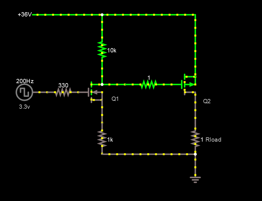 vivid rock
elder hare
is it at all possible to change the number of leds (using fastled) at runtime? :...
vivid rock
elder hare
is it at all possible to change the number of leds (using fastled) at runtime? :...
I do not think it is possible.
But you can indeed declare numLeds 2000 and then only use 200 leds in your patterns. Moreover, you can provide additional argument to show function so that it only pushes data for 200 leds
reddit
1 vote and 17 comments so far on Reddit
elder hare
@vivid rock what benefits would that give me by doing that? you can provide additional argument to show function so that it only pushes data for 200 leds
vivid rock
speed (and thus refresh rate). Pushing a frame of data for 2000 pixels takes 10 times as long as data for 200 pixels.
elder hare
gotcha!
north stream
@paper oracle If Q1 is off, its source would be at 0V so that's okay. However, when a 3.3V signal is sent to its gate, it will try to turn on, but the 1k resistor between its source and ground, forming a voltage divider. While it wouldn't violate the Vgs voltage, it would cause degeneration and keep Q1 from turning on very well. I'm unsure why that 1k resistor is present.
It does look like Q1 is being used as a level shifter to drive Q2, so you may need to pay attention to Q2's Vgs limits.
elder hare
@vivid rock hmmm it just crashes on me
rocky pivot
Can someone please help me interface the ArduinoMenu 4 for the 128x64 Oled FeatherWing (SH1107)?
north stream
It looks like it can use AdaFruit GFX, so it shouldn't be too hard to integrate
elder hare
this -> https://pastebin.com/5DhC8NcB
crashes my ESP32 why?
Guru Meditation Error: Core  1 panic'ed (StoreProhibited). Exception was unhandled.
Core 1 register dump:
PC      : 0x400d75ed  PS      : 0x00060a30  A0      : 0x800e0223  A1      : 0x3ffb1f90
A2      : 0x00000000  A3      : 0x3ffc1b84  A4      : 0x3ffc2cf0  A5      : 0x3ffc306c
A6      : 0x00000020  A7      : 0x3ffbc23c  A8      : 0x800d75e4  A9      : 0x3ffb1f70
A10     : 0x3ffc1b84  A11     : 0x00000001  A12     : 0x8bb32e72  A13     : 0x3ffc8a4c
A14     : 0x3ffb1f2c  A15     : 0x3ffb1f2c  SAR     : 0x0000000a  EXCCAUSE: 0x0000001d
EXCVADDR: 0x00000004  LBEG    : 0x400014fd  LEND    : 0x4000150d  LCOUNT  : 0xffffffff

ELF file SHA256: 0000000000000000

Backtrace: 0x400d75ed:0x3ffb1f90 0x400e0220:0x3ffb1fb0 0x40089dae:0x3ffb1fd0

Rebooting...
ets Jul 29 2019 12:21:46

rst:0xc (SW_CPU_RESET),boot:0x13 (SPI_FAST_FLASH_BOOT)
configsip: 0, SPIWP:0xee
clk_drv:0x00,q_drv:0x00,d_drv:0x00,cs0_drv:0x00,hd_drv:0x00,wp_drv:0x00
mode:DIO, clock div:2
load:0x3fff0018,len:4
load:0x3fff001c,len:1044
load:0x40078000,len:10124
load:0x40080400,len:5828
entry 0x400806a8
Pastebin
Pastebin.com is the number one paste tool since 2002. Pastebin is a website where you can store text online for a set period of time.
north stream
It looks like the code caused a StoreProhibited exception, which in turn was not handled.
cedar mountain
The access of controller[8] in the constructor looks suspicious to me, since that was only declared as an 8-element array.
 bitter mirage
Hello there! I recently got a Circuit Playground Bluefruit, and I was hoping that there was a way to either sleep/shutdown the device with a button press when it's connected to a battery. is this possible?
 wispy crater
so i have a python code which looks like this
import requests

temprature = 29
moisture = 42
humidity = 35

result = requests.post('https://smartgardenuserdashboard.herokuapp.com/send_data/', json = {'Key': {'Username': 'SG', 'Password': 'password'}, 'Temprature': temprature, 'Humidity': humidity, 'Moisture': moisture})
print(result.text)
i want to do the same thing but with ESP8266
how to do that??
pls help
bitter mirage
@wispy crater hey there! Can you explain more? I'm not as familiar with Python, but I'm happy to help
wispy crater
bitter mirage
<@!579320358063046682> hey there! Can you explain more? I'm not as familiar with...
actually i am making a post request to https://smartgardenuserdashboard.herokuapp.com/send_data/
the data i am sending is in JSON format
the data is
{'Key': {'Username': 'SG', 'Password': 'password'}, 'Temprature': temprature, 'Humidity': humidity, 'Moisture': moisture}
so i want to do this in ESP8266

