#help-with-arduino
1 messages · Page 94 of 1
 stuck coral
 small pumice
ROFL. Oh @$##
small pumice
Jumper from TX to A3. Noted you said A3 would be Serial1RX. Did you mean Serial6RX? ```#include <Arduino.h> // required before wiring_private.h
#include "wiring_private.h" // pinPeripheral() function
Uart Serial6( &sercom4, A3, A2, SERCOM_RX_PAD_1, UART_TX_PAD_0);
void SERCOM4_Handler()
{
Serial6.IrqHandler();
}
void setup() {
// initialize both serial ports:
Serial.begin(9600);
Serial1.begin(9600);
Serial6.begin(9600);
}
void loop() {
// read from serial monitor, send to port 1:
Serial1.write(45);
// read from port 1, send to port 0:
if (Serial6.available()) {
Serial.println("Serial 6 saw something");
int outByte = Serial6.read();
Serial.println(outByte);
}
delay(1000);
Serial.println("x");
}```
 wispy crater
@stuck coral the server is complete!!
stuck coral
small pumice
Jumper from TX to A3. Noted you said A3 would be Serial1RX. Did you mean Seria...
Correct, I meant Serial6
wispy crater
i hosted it on repl.it
from pymongo import MongoClient
from flask import Flask
from flask import request
from datetime import datetime
app = Flask(__name__)

cluster = MongoClient(os.environ['cluster'])
db = cluster['overspeed']
table = db['cars']

@app.route("/")

def hello():
    return "Backend Server For Overspeeding Car Detector System"

@app.route("/add_value/")
def add_value():
    try:
        lat = request.args.get("lat")
        lon = request.args.get("lon")
        car = request.args.get("car_no")
        print(f'latitude: {lat}, longitude: {lon}')
        x = datetime.now()
        date = x.strftime("%d-%m-%Y")
        time = x.strftime("%I:%M:%S %p")
        arra ={"Date": date,"Time":time, "latitude":lat,"longitude":lon,"Car Number":car}
        if car == None:
            return "Aw Snap! Error Occured! Beep Boop Boop Beep!"
        elif lon == None:
            return "Aw Snap! Error Occured! Beep Boop Boop Beep!"
        elif lat == None:
            return "Aw Snap! Error Occured! Beep Boop Boop Beep!"
        else:
            table.insert_one(arra)
            return "Thanks for adding the values"
    except:
        return "Aw Snap! Error Occured! Beep Boop Boop Beep!"

app.run(host="0.0.0.0", port=8080)```here
and it works flawlessly
stuck coral
small pumice
Jumper from TX to A3. Noted you said A3 would be Serial1RX. Did you mean Seria...
This code wont work, hold on
Or, wont work correctly rather
#include <Arduino.h>   // required before wiring_private.h
#include "wiring_private.h" // pinPeripheral() function

Uart Serial6(  &sercom4, A3, A2, SERCOM_RX_PAD_1, UART_TX_PAD_0);

unsigned long next = 0;

void SERCOM4_Handler()
{
  Serial6.IrqHandler();
}


void setup() {
  // initialize both serial ports:
  Serial.begin(9600);
  Serial1.begin(9600);
  Serial6.begin(9600);
}

void loop() {
  // read from serial monitor, send to port 1:
  if(millis()>next){
    next = millis() + 10000;
    Serial1.write(45);
  }

  // read from port 1, send to port 0:
  if (Serial6.available()) {
    Serial.println("Serial 6 saw something");
    int outByte = Serial6.read();
    Serial.println(outByte);
  }

}
Well, actually scratch that
Since you send only one character it would have worked fine
So thats interesting, can you send from the Serial6 tx to Serial1 RX?
Oh, you are missing your pinPeripheral lines as well
@small pumice does changing both pinPeripheral(x, PIO_SERCOM); to pinPeripheral(x, PIO_SERCOM_ALT); fix the issue?
The SAMD51 datasheet differs slightly from the SAMD21 so its hard to tell what arduino wants, the pins are in what would be the SERCOM ALT column
wispy crater
hey @stuck coral , can you explain me how to format the URL?
stuck coral
wispy crater
hey <@!461746819345416203> , can you explain me how to format the URL?
Oh boy there's a big old document about this, URLs or actually URIs go like this scheme://username:password@host/path?var1=value1&var2=value2&num_val=3. We dont use a username or password here so we dont need those or the : @
wispy crater
like my link is
https://overspeed-backend-server.studiousgamer.repl.co/add_value/?lat=10&lon=10&car_no=DL110022&station=1
and i have the variables mylat, mylon, car and station which have the values for respective fields
so how to take the value from these variables and put them inside the link?
i tried this
"https://Overspeed-Backend-server.studiousgamer.repl.co/add_value/?lat=%f&lon=%f&car_no=%f&station=%f", mylat, mylon, car, ps
but on the serial monitor, https://Overspeed-Backend-server.studiousgamer.repl.co/add_value/?lat=28.650000&lon=77.250000&car_n this is showing only
stuck coral
Two issues, so remember your buffer? How long is it?
wispy crater
100
stuck coral
wispy crater
but on the serial monitor, `https://Overspeed-Backend-server.studiousgamer.repl....
How many characters is this?
brb
stuck coral
I need to brb but the last 1 is a null character, to make 100
stuck coral
wispy crater
you guys are genius lol
Not yet, getting there. So if you make the buffer larger, you will probably run into another issue where car_no and station appear as floats and Im not sure thats what they are
stuck coral
You changed what the formatting values for sprintf?
wispy crater
ye
https://Overspeed-Backend-server.studiousgamer.repl.co/add_value/?lat=%f&lon=%f&car_no=%s&station=%i
also
it is not working for some reason
stuck coral
Same issue?
wispy crater
sed
wispy crater
stuck coral
Same issue?
no everything is fine but the values are not being added
i didn't changed the code even a little bit
but instead of the myql link, i pasted https://Overspeed-Backend-server.studiousgamer.repl.co/add_value/?lat=%f&lon=%f&car_no=%s&station=%i this
and some formatting
stuck coral
Im not really sure what you mean, code?
stuck coral
Well I have no idea about anything past the microcontroller
wispy crater
when i tried to send the request with python, it worked fine but not working with ESP8266
requests.get("https://Overspeed-Backend-server.studiousgamer.repl.co/add_value/?lat=28.6500&lon=77.2500&car_no=DL 5 S AB 9876&station=1")```sed 😢
wispy crater
oke so i wanna read the D2 pin of ESP8266 so for that i am using #define IRSENSOR_PIN D2 but when i try to compile it, it says that 'D2' was not declared in this scope why?
@stuck coral any idea?
stuck coral
wispy crater
<@!461746819345416203> any idea?
Not sure, still have ESP8266 selected? If so, try just replacing D2 with 4
wispy crater
oke
it worked like a charm
thanks again!
also that mongodb wasn't actually required..
i just wanted to flex my python skills in front of judges.. that's the reason i thought i will use MongoDB and it looks better than mqsql too
 slim shell
How do I receive data wirelessly on a raspberry pi from an Arduino/esp32?
stuck coral
slim shell
How do I receive data wirelessly on a raspberry pi from an Arduino/esp32?
Are you asking how to do it over a Wi-Fi connection or are you thinking something else?
slim shell
stuck coral
Are you asking how to do it over a Wi-Fi connection or are you thinking somethin...
I suppose WiFi, I should have clarified. My bad
stuck coral
slim shell
I suppose WiFi, I should have clarified. My bad
Where are you trying to put the data?
slim shell
Somewhere locally on the Pi. I'm not quite sure what I'm looking for I guess
stuck coral
What type of data are you sending?
For example time-series like sensor data? Over an IP connection you have two popular options HTTP or MQTT
Which one to pick depends on how often you send and if you want the ESP32 to get downstream data right when sent, or if you want the ESP32 to be able to sleep
slim shell
Right now I am planning to send light levels and temperature. I'm not interested in deep sleep at the moment
stuck coral
If you're looking to quickly get a nice dashboard, I recommend using telegraf
You can configure a input plugin like HTTP or MQTT, and an output plugin for a database to store it, then use grafana to view your time series data
HTTP will remove the requirement of installing a broker
slim shell
These all seem to be exactly what I am looking for, much thanks! As for the database would you suggest the InfluxDB from the telegraf guys or some other db?
stuck coral
Not really, I like timescaledb but there is no real reason for me to recommend that over influxdb, both will do the same thing here
So its this, just change the input plugin to HTTP, then send a HTTP request to the pi from the ESP32 https://nwmichl.net/2020/07/14/telegraf-influxdb-grafana-on-raspberrypi-from-scratch/

Whether you are looking for a little test bed or an always-on home dashbording system, the RaspberryPi is a great, affordable platform for the TIG-Stack. So let’s ride through all the necessa…
slim shell
okay, thanks for all the help my dude!
 vivid rock
is it correct that there is yet no official support for Adafruit's RP2040-based boards in Arduino IDE? I know that the Raspberry Pi Pico was recently added to the list of officially supported boards (https://github.com/arduino/ArduinoCore-mbed/releases/tag/2.0.0) but yet there is no support for RP2040 Feather or ItsyBitsy?
small pumice
stuck coral
<@!448616830622367764> does changing both `pinPeripheral(x, PIO_SERCOM);` to `p...
It does not appear to. I tried both SERCOM_ALT and _SERCOM ```#include <Arduino.h> // required before wiring_private.h
#include "wiring_private.h" // pinPeripheral() function
Uart Serial6( &sercom4, A3, A2, SERCOM_RX_PAD_1, UART_TX_PAD_0);
unsigned long next = 0;
unsigned long next_clock = 0;
void SERCOM4_Handler()
{
Serial6.IrqHandler();
}
void setup() {
// initialize both serial ports:
Serial.begin(9600);
Serial1.begin(9600);
Serial6.begin(9600);
// Assign pins A2 & A3 SERCOM functionality
pinPeripheral(A2, PIO_SERCOM); // SERCOM_ALT?
pinPeripheral(A3, PIO_SERCOM);
}
void loop() {
// read from serial monitor, send to port 1:
if(millis()>next_clock){
Serial1.write(45);
Serial.println("serial 1 write");
next_clock = millis() + 10000;
//Serial.println("Next clock");
}
// read from port 1, send to port 0:
if (Serial6.available()) {
Serial.println("Serial 6 saw something");
int outByte = Serial6.read();
Serial.println(outByte);
}
// Serial.println(millis());
}```
stuck coral
small pumice
It does not appear to. I tried both SERCOM_ALT and _SERCOM ```#include <Arduino...
Anything if you change both PIO_SERCOM to PIO_SERCOM_ALT? After digging around in the datasheet thats the only thing I can see which is wrong
Well, probably wrong anyways
stuck coral
On the SAMD51 datasheet, its not called SERCOM_ALT, but its the SERCOM_ALT column in the SAMD21 datasheet
And yes
wispy crater
@stuck coral i am stuck again....
this time, i have to make a HTTPS request
stuck coral
If you dont require host key verification, just swap out WiFiClient for WiFiClientSecure and change the uri
wispy crater
that's it?
stuck coral
As long as you have the server setup, yeah.
wispy crater
umm i am using #include <ESP8266WiFi.h>
not wificlient
#include <ESP8266HTTPClient.h>
#include <SoftwareSerial.h>
#include "TinyGPS++.h"```all the libraries i am using
umm @stuck coral
stuck coral
wispy crater
all the libraries i am using
Yay the esp8266 tls libs are totally different from the esp32. I am at work and will need to come back to this later
small pumice
@stuck coral Any suggestions for a simpler approach? Otherwise I am going to have to disable the GPS wing, power up my tag reader with a non-latching relay, grab the serial info from RX, and swap back to GPS config. Seems inelegant at best when I just need a second serial port. FYI, the whole setup is Feather M0 with SD card, Ultimate GPS featherwing, RFM LoRa featherwing, and the external tag reader controlled by a non-latching relay (because it SUCKS UP POWER). The GPS uses the RX TX port already.
stuck coral
small pumice
<@!461746819345416203> Any suggestions for a simpler approach? Otherwise I am g...
I thought you said you were using the Feather M4 express, the code wont be portable between the two. But you can try software serial if needed
I gotta be working rn, can talk more about it later here if others dont
 noble obsidian
does anyone know where the arduino sketch is for the firmware shipped in the FunHouse ?
small pumice
stuck coral
I thought you said you were using the Feather M4 express, the code wont be porta...
My initial setup is M4 express, but I purchased the M0 to add the card capability.
small pumice
I figured since I know know what to look for, I can make the switch with the datasheet!
small pumice
Hurray and THANKS @stuck coral ```#include <Arduino.h> // required before wiring_private.h
#include "wiring_private.h" // pinPeripheral() function
Uart Serial6( &sercom4, A2, A1, SERCOM_RX_PAD_1, UART_TX_PAD_0);
void SERCOM4_Handler()
{
Serial6.IrqHandler();
}
void setup() {
Serial.begin(9600);
Serial6.begin(9600);
// Assign pins A1 & A2 SERCOM functionality
pinPeripheral(A1, PIO_SERCOM_ALT); // SERCOM_ALT?
pinPeripheral(A2, PIO_SERCOM_ALT);
}
uint8_t i=0;
void loop() {
//Serial.print(i);
//Serial6.write(i++);
if (Serial6.available()) {
Serial.print("from 6: ");
Serial.println(Serial6.read(), HEX);
}
}```
wispy crater
@stuck coral are you back?
 pine bramble
Hi guys, So im trying to send an IR signal from esp32 and im using the <IRremote.h> library for that (latest release does say it supports esp32 transmit) but i am getting no signal generated from it
LED is hooked up to GPIO4
And this is the basic sketch im running
void setup() {
  Serial.begin(115200);
}

void loop() {
  IrSender.sendNEC(0xFE1AE5, 32, 2); //Power Code
  Serial.println("Power");
}```
Any help would be really appreciated, ThanksDid it work?
stuck coral
wispy crater
<@!461746819345416203> are you back?
Not yet, will be home in 20-30
 vale iris
If anyone with an arduino nano 33 ble and a decent oscilloscope wants to help me test some code it would be much appreciated. DM me if your interested and I'll give u the details. Thanks.
 waxen hawk
Do anybody know where is a good website to partner with other people ? I have an idea for an arduino project with solenoids and I want to get better as a beginner programming in c and other hardware devices.
pine bramble
waxen hawk
Do anybody know where is a good website to partner with other people ? I have an...
Fiverr
waxen hawk
pine bramble
Fiverr
Isn't that to pay people?
pine bramble
waxen hawk
Isn't that to pay people?
Yeah, but you can get an experienced partner to work with you on your project
waxen hawk
umm the project is more for a hobby. In a different thread, people suggest a reddit post called r/programmingpals
actually, one of my friends suggest https://codebuddies.org/ (i haven't tried it)

We're a community helping each other via Slack, self-organized study groups, and virtual screensharing hangouts. Learning with others helps us learn faster. The project is free, open-sourced, and 100% community-built.
pine bramble
whatever you think is best for you, i suggested cause i have used services from fiverr for my projects in the past
waxen hawk
ah, out of curiosity, have you learned much programming when working with them and their services?
oh is it very one sided in that they entirely do the project for you?
pine bramble
Mostly yes
waxen hawk
i see. Thanks! This could work if I come to a situation if I really needed professional help.
pine bramble
waxen hawk
oh is it very one sided in that they entirely do the project for you?
it depends, You can pay them to do the whole project (just send them a requirements document) or You can just pay them to Guide you throughout the process
waxen hawk
pine bramble
it depends, You can pay them to do the whole project (just send them a requireme...
👍
noble obsidian
noble obsidian
does anyone know where the arduino sketch is for the firmware shipped in the Fun...
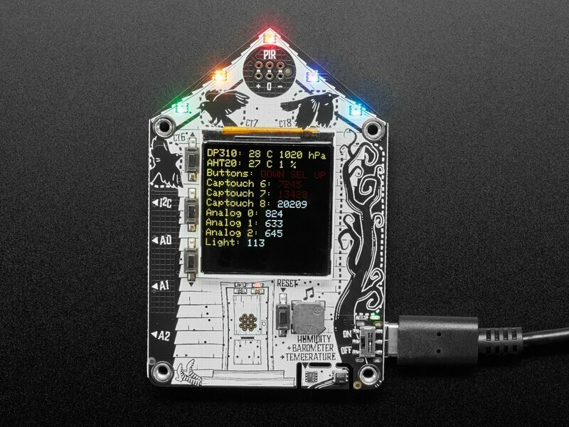
Found the FunHouse arduino sketch in the new learn guide - here: https://learn.adafruit.com/adafruit-funhouse/arduino-self-test-example
and on github: https://github.com/adafruit/Adafruit_Learning_System_Guides/tree/master/FunHouse_Arduino_Demos

GitHub
Programs and scripts to display "inline" in Adafruit Learning System guides - adafruit/Adafruit_Learning_System_Guides
wispy crater
this is showing in my serial monitor
http://Overspeed-Backend-server.studiousgamer.repl.co/add_value/?lat=28.6500&lon=77.2500&car_no=DL 5 S AB 9876&station=1
<!DOCTYPE html>
<html lang=en>
  <meta charset=utf-8>
  <meta name=viewport content="initial-scale=1, minimum-scale=1, width=device-width">
  <title>Error 400 (Bad Request)!!1</title>
  <style>
    *{margin:0;padding:0}html,code{font:15px/22px arial,sans-serif}html{background:#fff;color:#222;padding:15px}body{margin:7% auto 0;max-width:390px;min-height:180px;padding:30px 0 15px}* > body{background:url(//www.google.com/images/errors/robot.png) 100% 5px no-repeat;padding-right:205px}p{margin:11px 0 22px;overflow:hidden}ins{color:#777;text-decoration:none}a img{border:0}@media screen and (max-width:772px){body{background:none;margin-top:0;max-width:none;padding-right:0}}#logo{background:url(//www.google.com/images/branding/googlelogo/1x/googlelogo_color_150x54dp.png) no-repeat;margin-left:-5px}@media only screen and (min-resolution:192dpi){#logo{background:url(//www.google.com/images/branding/googlelogo/2x/googlelogo_color_150x54dp.png) no-repeat 0% 0%/100% 100%;-moz-border-image:url(//www.google.com/images/branding/googlelogo/2x/googlelogo_color_150x54dp.png) 0}}@media only screen and (-webkit-min-device-pixel-ratio:2){#logo{background:url(//www.google.com/images/branding/googlelogo/2x/googlelogo_color_150x54dp.png) no-repeat;-webkit-background-size:100% 100%}}#logo{display:inline-block;height:54px;width:150px}
  </style>
  <a href=//www.google.com/><span id=logo aria-label=Google></span></a>
  <p><b>400.</b> <ins>That’s an error.</ins>
  <p>Your client has issued a malformed or illegal request.  <ins>That’s all we know.</ins>```

i know that i am making a request with http even it is https but still is there a way to bypass this?? cedar mountain
This may be problematic: car_no=DL 5 S AB 9876Typically embedded spaces are a no-no, so you'd want to be sure your URL is properly escaped.
wispy crater
when i enter this url in my browser, it works but it doesn't here
cedar mountain
Browsers are typically smart enough to fix what people type in, but I expect the actual URL it sends to the server is escaped.
wispy crater
well the https is now working so i do not need that code anymore
😅
sorry to bother you
cedar mountain
No worries, glad you got it working.
wispy crater
😁
 tacit socket
Hi
I am using Itsy Bitsy nRF52840 with Arduino IDE and the latest bootloader from Adafruit
The problem I've got stuck it's that I am using Adafruit_LittleFS to store files, I need to store ~200kB in flash so after resetting that part of memory wouldn't change, but the current bootloader leaves just 28kB for User Data. Is there any trick in how I can change the partition in the easiest way?
I imagine this like a change memory address in the current bootloader just to swap some memory from Application to User Data. But don't know where to dig in.
Any help appreciated
vivid rock
@tacit socket Itsy Bitsy nRF52840 has a 2Mb external flash memory on board which you can access using Adafruit SPIFlash library - would this work for you?
tacit socket
@vivid rock Wow, I don't know. Is that memory would be retained after the reset?
vivid rock
yes
You can even make the board appear as external USB drive when connected to the computer, so you can just drag-and drop files from your computer to that flash memory
(This requires Adafruit TinyUSB library)
But I have no experience with LittleFS library; I have used SdFat to format the flash memory chip
tacit socket
I wondering that Itsy Bitsy have additional 2Mb flash onboard
After prototyping stage I plan to create custom PCB on nRF52840 and I am sure that adding external SPI flash memory chip would add costs, that's why I would still digging into changing partition. Seems from what I found I can change address of User Flash in nRF52840 but need Jlink and manuals "smoking" for building custom bootloader image. Itsy Bitsy SPI flash it's great workaround for now. Many thanks @vivid rock
vivid rock
Oh, I see.
Unfortunately changing the bootloader or partition is beyond my skills at the moment.
But as a backup plan, external QSPI flash chips are cheap - something like $0.50: https://www.digikey.com/en/products/detail/gigadevice-semiconductor-hk-limited/GD25Q16CSIGR/9484689
Order today, ships today. GD25Q16CSIGR – FLASH - NOR Memory IC 16Mb (2M x 8) SPI - Quad I/O 8-SOP from GigaDevice Semiconductor (HK) Limited. Pricing and Availability on millions of electronic components from Digi-Key Electronics.
tacit socket
Good to know btw 🙂
@vivid rock thanks
small pumice
stuck coral
Did it work?
Yup. Now working on layering the logic with the GPS serial on the TX port. Any suggestions which forum do you think I should ask in for help with GPS feather board settings? I was looking in projects, but there does not seem to be much help available there.
stuck coral
small pumice
Yup. Now working on layering the logic with the GPS serial on the TX port. Any...
#help-with-projects is the typical by default help like this, what do you mean by settings?
small pumice
I am trying to slow down the reporting rate. The settings are a bit obtuse. I want data every 30 seconds, vs. every second, and when I tried it, I got errors. This is a forward looking question, as I have not finished integrating my parts.
cedar mountain
Looking at the command reference, it seems like the update rate maxes out at 10 seconds. I think that would be done with the config command$PMTK220,10000*2F<CR><LF>
Oh, there's even a constant for that in the Adafruit library:PMTK_SET_NMEA_UPDATE_100_MILLIHERTZ
small pumice
cedar mountain
Looking at the command reference, it seems like the update rate maxes out at 10 ...
Thanks!
 rough torrent
Hey I have 3 Arduinos - 2 Unos and a Mega. One of the Unos works (like I can program it and a sound plays when I connect and disconnect it) while the other 2 still seem to run their sketch but when I plug them in they don't appear anywhere, not even in device manager. No sound is played when I plug/unplug those 2.
What I've checked:
- Faulty USB cable - well it can't be broken as I used the same cable for all 3 Arduinos and only one of them appears
- Bad USB port - same as above
- Bad drivers - same as above
- Physically broken - they don't appear to be damaged
- Bootloaders bad - tried to flash new ones and success message when flashed but nothing changes
One thing I've noticed is that on the good Uno that the little yellow chip right next to the USB B connector says 50bU while on the bad one it says 50bY - could that be related? I've also may or may not have overheated that chip on the bad Uno but the Arduino still lights up and everything.
Is there anything else I've missed? I'd appreciate any pointers ♥️
(Also ping if you respond)
 green heath
are they genuine? I remember that the chinese knockoffs have a different chip and need a driver. but thats pretty much all I know.
 green heath
whats the problem?
green heath
it helps if you tell what the problem is. you can just find working code as well
 acoustic mountain
I’ve tried a lot of codes from youtube, avrfreaks and other forums but none of them worked 🥴
Surely im doing something probably wrongly
green heath
the only thing I can say so far is that your pinout wont work. most servo's need a PWM signal of 20Mhz. with a pulselengt of 2 to 4 mHZ
green heath
there is only one timer capable of doing that and that is timer1 on an uno
acoustic mountain
Timer1 ctc oc?
green heath
timer1 has a mode where the top is ICR1. so you dont have to use CTC and save a hardware PWM pin. but CTC is also possible
acoustic mountain
Uhum understand
Tomorrow can you help me if you have some free time?
And if you want of course
No problem if you cant
green heath
I cant. I need to finish school stuff.
acoustic mountain
This is for me school stuff too 😅
green heath
coincidentally, a project where I had to power 2 servo's
acoustic mountain
And you are coding with AVR C?
acoustic mountain
And if you finished with coding servo, can you send me the code?
Probably i can use it
green heath
only if you know how to change the interrupt registers 😉
mine works on timer3 of an atmega
green heath
yes
vivid rock
green heath
the only thing I can say so far is that your pinout wont work. most servo's need...
20 Mhz????
typical servo control is PWM with period of 20 ms (thus, frequency 50 hz) and pulse width varying from 500 to 2500 microseconds
https://www.servocity.com/servo-faqs/#how-do-i-control-a-servo
Welcome to ServoCity where you can get the parts you need to bring your ideas to life! From servos to switches, from actuators to Actobotics, we work hard to bring you the best components backed by unparalleled technical support
acoustic mountain
Right 🤣
vivid rock
🙂
green heath
errr. I dont have my code with me so I cant check the actual speed of my timer
acoustic mountain
👍
green heath
top of my head calculator calculation its a 2.5ms pulse
but that seems wrong
oh yup got it. its 20ms indeed. top in ICR, and the right prescaler.
 elder hare
so when controlling a LED Strip in the main loop i control the updating of the pattern via Millis this presented a problem as i control the led Strip via an Qt App i made to send commands to my ESP32 like brightness and stuff (this via socket)!
The problem:
If the strip is set to low delay (meaning the pattern runs slow) when i then send brightness values to the ESP32 since the pattern is inside that millis the data updates slow since delay is set low
Possible solution:
if i set the delay to a fixed value like 0 or 128 (half speed) and instead of controlling the Delay i set the Incrementing Position variable from int to float and set the incoming delay value from Qt App to Position += Delay; wouldn't this fix the problem where the data updating of the pattern is slow because of the millis update?
 north stream
That's one possible fix. Another approach could be to send an update to the strip when a brightness change is received.
acoustic mountain
Why is my servo moving strangely?

#include <avr/io.h>
#include <stdio.h>
#include <stdlib.h>
#include <stdint.h>
#include <stdbool.h>
#include <assert.h>
#include <avr/interrupt.h>
#include <avr/wdt.h>
#define F_CPU 16000000
#include <util/delay.h>
void setup()
{
ADC_init();
Servo_init();
while(1)
{
OCR1A = 65 + (ADC_measure(0)/4.35);
}
}
void Servo_init()
{
DDRB |= (1 << PB1);
TCNT1 = 0;
ICR1 = 2499;
TCCR1A = (1<<WGM11)|(1<<COM1A1);
TCCR1B = (1<<WGM12)|(1<<WGM13)|(1<<CS10)|(1<<CS11);
}
void ADC_init()
{
//Referencia: külső 5V
//ADMUX – ADC Multiplexer Selection Register
//Bit 7:6 – REFS1:0: Reference Selection Bits
//0 1 AVCC with external capacitor at AREF pin
ADMUX |= (1<<REFS0); //ADC Multiplexer Select
//Orajel előosztás: 50-200kHz közötti értékre
//200kHz 16000kHz 80x - 128 előosztás
//ADCSRA – ADC Control and Status Register A
//ADPS2 ADPS1 ADPS0 1 1 1 128
ADCSRA |= (1<<ADPS2) | (1<<ADPS1) | (1<<ADPS0);
//Mód: normal, free running - alapértelmezett
//EN
ADCSRA |= (1<<ADEN);
}
uint16_t ADC_measure(uint8_t ch)
{
//Csatorna választása
//várakozás az átalakítás végére - IT flag
//ADMUX – ADC Multiplexer Selection Register
//Bits 3:0 – MUX3:0: Analog Channel Selection Bits
//MUX3 MUX2 MUX1 MUX0 - 0000-0111: ADC0-ADC7
ADMUX |= ch&0x07;
//ADC érték kiolvasása
//START - indítás
ADCSRA |= (1<<ADSC);
//Várakozás az átalakítás végére
//Bit 4 – ADIF: ADC Interrupt Flag
while(!(ADCSRA & (1<<ADIF))); //amig a FLAG egy
//ADIF mögött: #define ADIF 4
//(1<<ADIF) -> (1<<4) -> 0b00010000
//ADCSRA & (1<<ADIF) -> ADCSRA & 0b00010000
//ADCSRA & 0b00010000 -> 0b00000000, ha az ADIF bit az 0 - hamis
//ADCSRA & 0b00010000 -> 0b00010000, ha az ADIF bit az 1 - igaz
//Csatorna felszabadítása
ADMUX &= ~ch;
return ADC;
}``` reef ravine
@acoustic mountain try connecting something to A0, it follows light levels when i attach an LDR voltage divider with no jitter IRL
 grand kite
Hi guys, I come from a software background and am new to electronics.
I'm working on the following project and need some advice:
- I've got a 20x20 matrix of ws8212b RGB LEDs being driven by an isolated(Not attached to Arduino) ATmega328.
- This "matrix" is actually more of just a long strip of 400 LED's daisy chained together to represent a 20x20 matrix.
- I currently have the following circuit set up from a Youtube tutorial, where I've isolated the ATmega328 on a breadboard (https://imgur.com/a/zr5dahy).
- In the image, the resistor is 10k, the two ceramic capacitors are 22pf and the electrolytic one is 10uf.
- Both the ATmega328 and ws8212b LEDs operate at 5 volts. For this reason I would like for them to share a power supply.
The questions I have are:
-
Due to the very long chain of LEDs, I understand that I should use some power injection. Would there be any issue with power injecting on every row, or should I power inject only a few times where necessary?
-
As each of the LEDs can potentially draw 60mA (20+20+20) each when at full brightness and I have 400 LEDs, the max current draw of the strip would be 24 amps or 120 watts.
If I were to use a power supply of 5v 24a to power the circuit in the imgur image, with the LED strip connected to one of the IO pins and the 5v in and ground connected to the same power supply as the ATmega328 would there be any issues here? Would the ATmega328 be at risk? Does the 10uf capacitor need to change with a current that high? -
For this project, I don't ever intend to have every LED white at full brightness. In fact, I only want the LED's to be at 50% brightness at most and I'll only be using around 150/400 of them at any given time. With this considered, would you recommend to go for a lower amp power supply? If I did accidentally go too low (say, 2 amps), could I end up damaging my components by drawing the maximum rated current of the PSU? Or would the LED's just simply be less bright?
elder hare
trying to use msgpack packer but im confused as to how to use the packer
                if (mIndata["reqDeviceInfo"])
                {
                    packer.to_map("devicetype", Config[DeviceConfig].Device_Type,
                                  "devicename", Config[DeviceConfig].Device_Name,
                                  "ledtype", Config[DeviceConfig].LED_Type,
                                  "stripnumled", Strips[_selectedStrip]->_NumLeds,
                                  "brightness", Strips[_selectedStrip]->GeneralSettings.Brightness,
                                  "patternActive", Strips[_selectedStrip]->GeneralSettings.ActivePattern,
                                  "patternDirection", Strips[_selectedStrip]->GeneralSettings.Direction,
                                  "patternDelay", Strips[_selectedStrip]->GeneralSettings.Delay,
                                  "patternSpacing", Strips[_selectedStrip]->GeneralSettings.Spacing,
                                  "patternTail", Strips[_selectedStrip]->GeneralSettings.Tail,
                                  "colorMode", Strips[_selectedStrip]->Color.ColorMode,
                                  "colorHue", Strips[_selectedStrip]->Color.Hue,
                                  "colorSaturation", Strips[_selectedStrip]->Color.Saturation,
                                  "colorFadeHueStart", Strips[_selectedStrip]->Color.Fade.Start,
                                  "colorFadeHueEnd", Strips[_selectedStrip]->Color.Fade.End,
                                  "colorFadeDelay", Strips[_selectedStrip]->Color.Fade.Delay,
                                  "gradientScrolling", Strips[_selectedStrip]->Color.Gradient.isScrolling,
                                  "gradientDelay", Strips[_selectedStrip]->Color.Gradient.Delay);

                    webSocket.sendBIN(num, packer);
                }
GitHub
MessagePack implementation for Arduino (compatible with other C++ apps) / msgpack.org[Arduino] - hideakitai/MsgPack
i dont understand how to send this huge list with differente types
vivid rock
grand kite
Hi guys, I come from a software background and am new to electronics.
I'm workin...
some suggestions:
- power injection on each row shouldn't create any problems, but is unnecessary. every other row, or every 4th row should be enough.
- I'd recommend at least 10A power supply. If it is a good quality supply, there should be no problems powering ATmega from it as well. You can use e.g. https://www.adafruit.com/product/658 or a MeanWell supply such as https://www.amazon.com/dp/B085QKVLB6/ . Any decent power supply should have overload protection, so if you try to draw too much current, nothing will be damaged - but the voltage will drop so the LED will be less bright, and the ATmega might start resetting
- as per Adafruit Neopixel Uberguide: https://learn.adafruit.com/adafruit-neopixel-uberguide/powering-neopixels, it is also highly recommended to add a 1000uF capacitor near the power connection for ws2812b
 stiff arrow
Here's a question I should have asked before spending all day soldering, can the serial ports on the Feather M0 Basic Proto handle 2 stop bits?
grand kite
@vivid rock you're a legend mate, thankyou so much.
cedar mountain
stiff arrow
Here's a question I should have asked before spending all day soldering, can the...
Seems so. From the USART section of the datasheet: "Supports serial frames with 5, 6, 7, 8 or 9 data bits and 1 or 2 stop bits." It'd be unusual if a UART peripheral wouldn't support that.
acoustic mountain
#include <avr/io.h>
#include <stdio.h>
#include <stdlib.h>
#include <stdint.h>
#include <stdbool.h>
#include <assert.h>
#include <avr/interrupt.h>
#include <avr/wdt.h>
#define F_CPU 16000000
#include <util/delay.h>
void EEPROM_write(unsigned int uiAddress, unsigned char ucData);
unsigned char EEPROM_read(unsigned int uiAddress);

unsigned int ucAddress = 10;
unsigned char ucData = 50;
unsigned char read;

void setup()
{

      Serial.begin(9600);

      EEPROM_write(ucAddress, ucData);

     read = EEPROM_read(ucAddress);

      Serial.println(read);
}

void EEPROM_write(unsigned int uiAddress, unsigned char ucData)
{
/* Wait for completion of previous write */
  while(EECR & (1<<EEPE));
  /* Set up address and Data Registers */
  EEAR = uiAddress;
  EEDR = ucData;
  /* Write logical one to EEMPE */
  EECR |= (1<<EEMPE);
  /* Start eeprom write by setting EEPE */
  EECR |= (1<<EEPE);
}

unsigned char EEPROM_read(unsigned int uiAddress)
{
/* Wait for completion of previous write */
  while(EECR & (1<<EEPE));
  /* Set up address register */
  EEAR = uiAddress;
  /* Start eeprom read by writing EERE */
  EECR |= (1<<EERE);
  /* Return data from Data Register */
  return EEDR;
}```Why EEPROM's read value always 0?
Somebody can help me?
cedar mountain
You might try inspecting the EEPE bit after the write call to see whether it indicates a write in progress. Apparently you have to set EEMPE and EEPE within 4 clock cycles of each other for the write to trigger, so that might not be necessarily guaranteed in C.
acoustic mountain
this code is from atmega328p's datasheet
so i dont know what's wrong
page 22
tacit socket
Hi. Every one. I am connecting IPS display based on ST7789
link: https://aliexpress.ru/item/1005002022123847.html?spm=a2g0o.productlist.0.0.25db740ecZ2Ppj&algo_pvid=d486ef9b-302d-415f-b630-8f4b063c1177&algo_expid=d486ef9b-302d-415f-b630-8f4b063c1177-3&btsid=0b8b037216192672530104143e06e3&ws_ab_test=searchweb0_0,searchweb201602_,searchweb201603_&sku_id=12000018443189656
(it's haven't CS pin but I am not using any other device on SPI so I think it's fine)
That display is very similar to Adafruit product:
https://www.adafruit.com/product/3787
And based on same screen:
https://www.adafruit.com/product/4421
I am connecting to Itsy Bitsy nRF52840 and using Arduino_ST7789 library which is based on Adafruit_ST7789. It's working but only with software SPI. I can't make it working on HW SPI I've tried different init setup without any luck using both libs, just black screen. Just want to know some thoughts why it's not working with HW SPI.
Thanks

We've been looking for a display like this for a long time - it's only 1.5" diagonal but has a high density 220 ppi, 240x240 pixel display with full-angle viewing. It looks a ...

This is a screen for advanced hackers who like the look of the TFT screen we've put into the TFT Gizmo and Monster M4sk. The 1.54" display has 240x240 16-bit full color pixels and ...
north stream
@acoustic mountain There are some weird timing/reset quirks with EEPROM writing. Someone else had a possibly-related issue previously, and posted some useful links: #help-with-arduino message
elder hare
https://pastebin.com/raw/2QTYDW4h moving the slider fast from left to right crashes the ESP32 :S this did not happen when using ArduinoJson
is it memory problem or what :S i can't figure out the error msg
north stream
I have no way of knowing, but the ESP32 is juggling several things at once (some time critical) so I'm guessing it gets interrupted at the wrong moment or there's a resource conflict as it tries to keep up.
elder hare
i've disabled the FastLED part of the code so now it's only WebSocket and msgpack deserialization going on
am i using the wrong msgpack? hmmm
on the github it states
https://github.com/hideakitai/MsgPack
This library is only for serialize / deserialize. To send / receive serialized data with Stream class, please use MsgPacketizer.

GitHub
MessagePack implementation for Arduino (compatible with other C++ apps) / msgpack.org[Arduino] - hideakitai/MsgPack
acoustic mountain
acoustic mountain
Why is my servo moving strangely?
bump
north stream
Are the ADC readings correct?
stiff arrow
cedar mountain
Seems so. From the USART section of the datasheet: "Supports serial frames with ...
More testing points to something being wrong. I ran the same code on the Feather M0 Basic and an Ardunio Micro. The Feather is returns missing or corrupted data. Whereas the Micro return all data correctly.
void setup() {
  Serial1.begin(9600, SERIAL_8N2);
}

void loop() {
  if (Serial1.available() > 0){
    b = Serial1.read();
    if(b==42){
      Serial.write(b);
      Serial.write('\n');
    }else{
      Serial.write(b);
    }
  }
}```yepp
north stream
That narrows it down to a few lines of code. Ideally you want to send 1-2ms pulses every 20ms or so.
acoustic mountain
north stream
That narrows it down to a few lines of code. Ideally you want to send 1-2ms pul...
right
#include <avr/io.h>
#include <stdio.h>
#include <stdlib.h>
#include <stdint.h>
#include <stdbool.h>
#include <assert.h>
#include <avr/interrupt.h>
#include <avr/wdt.h>
#define F_CPU 16000000
#include <util/delay.h>
void setup()
{
      Servo_init();
      OCR1A = ICR1 - 10000;
}

void loop()
{

}


void Servo_init()
{
      /*rescaler N = 1 then TOP(ICR1) = 160000
    Prescaler N = 8 then TOP(ICR1) = 20000
    Prescaler N = 64 then TOP(ICR1) = 2500
    Prescaler N = 256 then TOP(ICR1) = 625
    Prescaler N = 1024 then TOP(ICR1) = 156.25*/

      //8-as előosztás
      //8 1 0 0 0 PWM, phase and frequency correct ICR1 BOTTOM BOTTOM
      DDRB |= (1 << PB1); //Servo motor kimenet
      ICR1 = 20000; //50Hz jel
    OCR1A = 1000; //set 1ms pulse  1000=1ms  2000=2ms
    TCCR1A = (1 << COM1A1);//COM1A1 Clear OCnA when match counting up,Set on down
    TCCR1B = (1 << WGM13)|(1 << CS11);// Phase and Freq correct ICR1=Top
}```Finally the servo motor is moving

Now i have to figure out how can i give a specific degree
north stream
The position should be proportional to the pulse width. Nominally 1ms = 0° and 2ms = 180° but most servos can't quite manage a full 180° sweep, and the timing varies somewhat as well. You don't want to try to position it farther than it will go, so it can make sense to try a more restricted range (like 1.3ms - 1.7ms) to start with and then figure out where those map to.
You'll probably see that there aren't a whole lot of timer values available in the useful range, so the available precision may be limited.
vivid rock
@acoustic mountain why not use an existing servo library?
acoustic mountain
vivid rock
<@399543735710646273> why not use an existing servo library?
i can't 😦
vivid rock
Oh. Rules of an assignment?
acoustic mountain
yepp
and i want to impress my professor 😅
because this one is not a copy-pasting thing
north stream
You're already using timers, I'm just suggesting you carefully experiment with values and observe the effects on the servo, to determine the useful range available. Once you have that, you can measure the servo positions and from there calculate the timer value to servo position mapping.
acoustic mountain
Wow what a useful tip! Thanks @north stream !
my other question is, can i use servo motors with PORTC? 🤔
i dont have enough pins, that is why I'm asking
north stream
I don't remember the details of the timer-pin mapping offhand, so I don't know.
acoustic mountain

i guess i have to search for some code that matches my requirements of connected ports
 wet crystal
Not sure if arduino or radio specific
Thought about doing some smarthome control with ham radio and dtmf codes
What made me curios now if I can just play audio to the mic input with an analog signal straight from the arduino
To repeat something like "OK"
 torpid reef
There's no reason you can't do that, there's plenty of PICs and AVRs out there as APRS beacons that do this
wet crystal
@torpid reef I just thought about using one of my spare cheapo hams and hook up the the headphone jack to an DTMF decoder board, which is wired to an esp, which just transmit the data to the rpi which decides what to do with the data
But also let the esp expect some kind of start and stop tone before it transmit the data
Like 0 code 9
If the rpi decides it's valid it sends the confirmation to the esp which just outputs"ok" to the ham, which what I can receive on any ham tuned to that frequency
But also just basic commands like spray air refresher
Is that even an idea you would do or not, because it's a security flaw when I'm not sending digitally encrypted which wasn't planned
 proven mauve
okay, here's one... anyone know if you can use a keyboard to send information to a 32U4's usb? All my googling ends up with making the 32U4 into a keyboard lol
cedar mountain
For that you'd need to have the 32U4 act as a USB host instead of a USB device, and I don't think it can.
proven mauve
that makes sense
Did you see that hackaday article a while ago about the RGB electronic component storage system? Was trying to think of a decent arduino solution to run the software but the interface is where I'm not quite hitting home runs
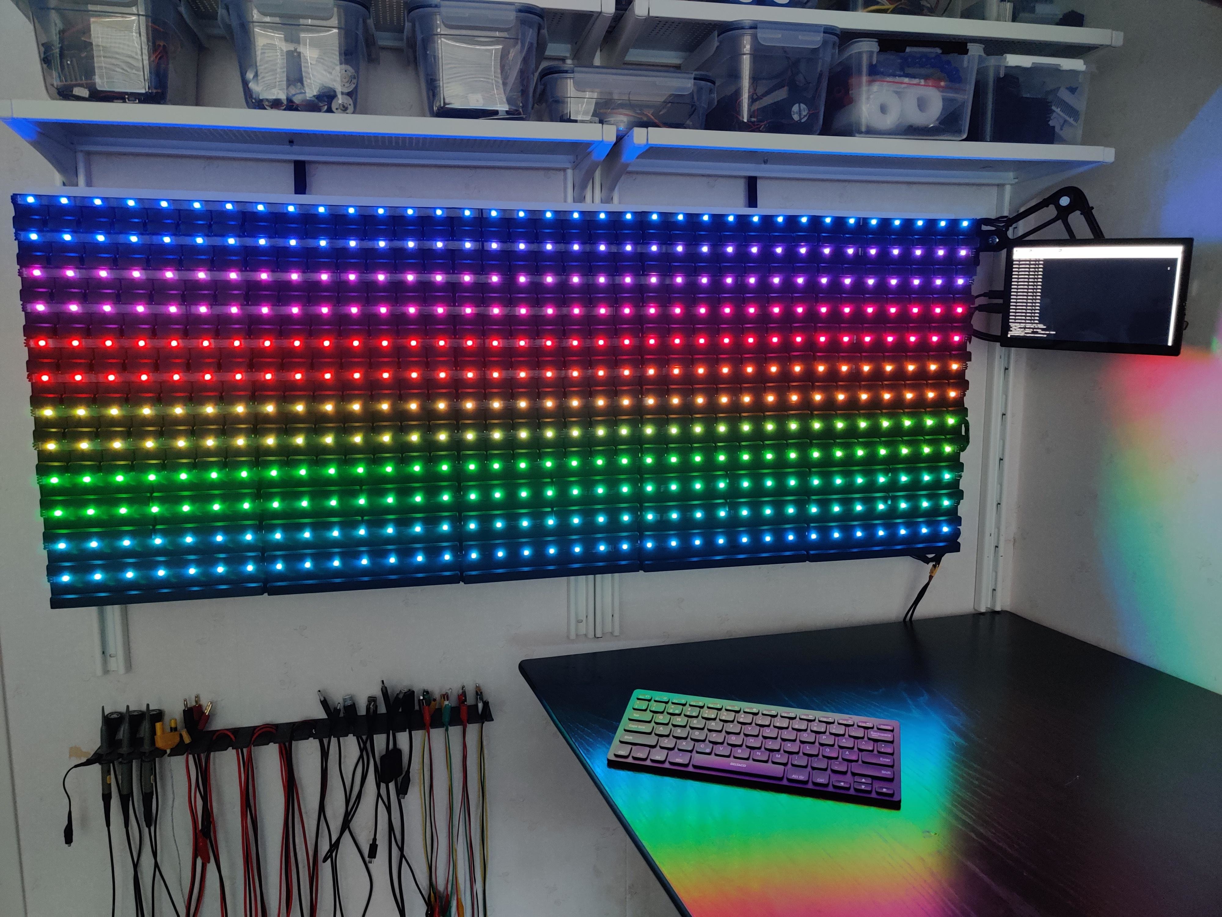
Think you’ve seen the best component storage system? This system could only be better if you could walk up and talk to it. [APTechnologies] was tired of using a hodgepodge of drawers and boxe…
I'll probably end up using a pi zero but it still seems like overkil
torpid reef
wet crystal
Is that even an idea you would do or not, because it's a security flaw when I'm ...
So there's no technical reason that wouldn't work, though I'd do morse code letters to signify status rather than have it try to talk... The thing is, you really do have to consider the security of the thing, because as you say, there's no encryption, and there's certainly no authentication that the right person is sending DTMF to control whatever it is you had hooked up. Replay attacks would just be a matter of recording the DTMF strings and playing it back while transmitting.
Honestly, DTMF-over-ham-radio is probably the last thing I'd consider for controlling a new home automation project just because of how insecure it is. I'm not trying to discourage you here, if you want to experiment, by all means, do so, but just be aware of the limitations of what you're implementing. 🙂
 molten bramble
anyone here have experience cleaning up noise / better debouncing with arcade buttons? Im getting a lot of false positives on a digital pin in
acoustic mountain
Somebody used EEPROM without library?
wet crystal
molten bramble
anyone here have experience cleaning up noise / better debouncing with arcade bu...
You could add a small capacitor or do it by software with a debounce function
 unborn frost
Hey, I need help with my esp32. It turns on and the red led flashes and there is a rapidly flashing blue led. But nothing connected is doing anything and the serial moniter
wont open giving the "Port Busy" error. any debugging suggestion
 dusky jay
Hi, I am trying to setup the trellis LED keypad to command my servos running through a motorshield v2. Both work independently (the buttons and motors) but whenever I try to run both the trellis keypad and motorshield in the same sketch the motors do not work. i2c addresses aren't overlapping and I can't find anything online. Any ideas?
As long as I don't call the trellis.begin() function, motor works fine.
https://learn.adafruit.com/adafruit-trellis-diy-open-source-led-keypad/overview
https://learn.adafruit.com/adafruit-motor-shield-v2-for-arduino

Adafruit Learning System
Trellis is an open source backlight keypad driver system. It is easy to use, works with any 3mm LEDs and eight tiles can be tiled together on a shared I2C bus.

Adafruit Learning System
Stackable, high current DC and Stepper motor shield
unborn frost
Having trouble with my Serial connection with my arduino boards and my pc. It always says that the port is "busy" I have tried with multiple boards with the same issues, I restarted my pc and everything was working fine last week. any suggestions?
 opaque matrix
@unborn frost check to make sure no other applications are using the serial port
 molten maple
How are you measuring the voltage? Are you measuring using an oscilloscope or using a multimeter? Peak voltage or average voltage?
likely it is working perfectly with a peak voltage of 5V and an average voltage of 5*125/255 volts as coded
Check out on the web what a PWM waveform looks like. It is likely to be running at 5V when on duty and 0V at off duty
A DMM can’t do much except indicate average voltage on the DC setting
You would need oscilloscope to see the waveform
I think it is working as intended
proven mauve
torpid reef
So there's no technical reason that wouldn't work, though I'd do morse code lett...
@wet crystal what about hashing everything you send with keys? That would be a start at least, prevent very low effort attacks
I guess you'd need a clock or something too to prevent replay attacks
 wind isle
Good morning! I am working on coding my project and I'm pretty happy with the Fast LED "TwinkleFox" codes provided already in the examples, but I'm wondering if anyone can help me add a new color palette or change the colors of an existing palette in the code? I don't see any specifics as to where I can alter a color. I need a more orange/yellow/Halloween theme and the fairy lights, while close, is too white.
Here is a copy of the fairylight palette for reference. Thank you so much for your help!
// A pure "fairy light" palette with some brightness variations
#define HALFFAIRY ((CRGB::FairyLight & 0xFEFEFE) / 2)
#define QUARTERFAIRY ((CRGB::FairyLight & 0xFCFCFC) / 4)
const TProgmemRGBPalette16 FairyLight_p FL_PROGMEM =
{ CRGB::FairyLight, CRGB::FairyLight, CRGB::FairyLight, CRGB::FairyLight,
HALFFAIRY, HALFFAIRY, CRGB::FairyLight, CRGB::FairyLight,
QUARTERFAIRY, QUARTERFAIRY, CRGB::FairyLight, CRGB::FairyLight,
CRGB::FairyLight, CRGB::FairyLight, CRGB::FairyLight, CRGB::FairyLight };
I did find CRGB color codes on FastLEDs website! But I'm still getting a lot of white in between the other colors that I have managed to change! So progress!
I've gotten closer still! But I'm not sure where the adjacent colors of green or red are coming from if I change all of the code to dark orange and yellow.
wind isle
Hello! Yes I just got back from lunch! Yes it is for neopixels!
I am closer but I see green and blue lights occasionally not just the colors I coded. Changing the /2 and /4 maybe helped but I’m not sure. Lol
proven mauve
I have a feeling it's from the way the brightness or colors work while twinkling. Since those colors are adjacent to the ones you're working with, I'm pretty sure they're easy to make by adjusting the values just a bit in that direction. A haven't gotten too far under the hood of how twinklefox works, but if you're working with an 0x000000 color code (which usually libraries like this are) it's easy to bump into other colors by using math functions to cycle through the numbers, if that makes sense
wind isle

I am changing the color code. I did consider that too and was thinking more red-leaning colors might work? I have no concept of changing it with math.
proven mauve
Like for example, here's 3 of the colors inside the code:
#define C9_Red 0xB80400
#define C9_Orange 0x902C02
#define C9_Green 0x046002
in case you weren't tracking the codes work like this, 256 values each of red, green, and blue to make all the colors
wind isle
Okay I do see that in another palette!
proven mauve
so they're 0xRRGGBB, and each of those digits can be zero-9 and then A-F are higher values after 9, which is how you get 256 values with two digits
so if you look at those three color codes, red has lots of red, a tiny bit of green and no blue
wind isle
Right
proven mauve
then orange has a little less red and more green, and a tiny bit of blue
then to make green, all you do is lower the value of the red, and suddenly your orange becomes green
wind isle
Ahh okay. Interesting!
proven mauve
yeah, it's really crazy the way colors work, it's the opposite of using paint on a canvas where ou mix colors and things become darker, and if you mix all the colors you get black. With LEDs the pallete is reversed becaue you're increasing the values of the colors and when you increase them all you get solid white
wind isle
So how do I exclude the green or blue from the code? I suppose I just expected if I put in the code to read "orange" they would all be orange, but they turn green as well.
hm
There's this one here that you got the code from that's "retro" and I kind of wonder what it would look like if I changed them all to specifically red/orange/yellow tones.
Imma do it.
pine bramble
@compact kiln made a color compositor box to test RGB values on the fly.
proven mauve
So, what I would do is max a min and max value each color can travel to, so that they always stay within the bounds of what you want to see
but it may end up being a little bit of work to code, using less of the premade stuff
pine bramble
wind isle
Ah. I'm not sure how to do that but I will look into it!
proven mauve
Nis to the rescue 😄
So, there are adafruit libraries that push colors out to neopixels
and you can enter 0x000000 color codes. So I would make loops that change red, green, and blue values individually over time, and then push them out to the pixels
pine bramble
afaik the eye responds to light 'logarithmically'.
proven mauve
then it's easy to define a min and max color zone, and speed, all that
proven mauve
No worries, good luck!
Nis, I'll be home in a couple weeks and I should have a jlink waiting for me. I'm really excited to start using one for debugging
wind isle
This is my first project so I'm still in the "find line, replace with other line" stage of learning.
BUT LOOK!
proven mauve
haha, yeah, I feel that. Have you messed with making for loops to cycle values before?
wind isle
 proven mauve
For the horde? 😄
wind isle
No! I was really struggling to find code that I liked the look of. Every code I found didn't work it only lit one neopixel!
(Yes I am! But this is Ashe from Overwatch!)
proven mauve
A lot of times there's a #define or something at the top to tell it how many pixels you have connected
wind isle
I wanted it to do the "breathing" look but none of the codes worked. Even when I changed the define. But maybe I didn't do it right. Anyway! When I found this cute twinklefox code I really liked the idea so now it's just getting the colors right.
proven mauve
so, a lot of neopixels have a fourth value for brightness, outside of the color values. To do breathing you would make that brightness value larger or smaller
pine bramble
'breathing' would mean a constant stream of new values to the (addressible) RGB strip.
proven mauve
Caitlin, what I would work with is the strandtest_wheel example in the neopixel examples and go from there
wind isle
I guess I understood the theory but I couldn't figure out the code. I will keep trying!
pine bramble
fade.ino for a singleton ('analog') LED shows the principle.
wind isle
Thanks! I will look at it again! ❤️
pine bramble
wind isle
Oh thanks!!!
Now I see here in some of the other examples there are fades that happen on multiple pins. But if I'm using just pin 3 (trinket m0) how can I use this code? Do I just cut out the other pins?
wind isle
Well good news is I got the colors and code how I wanted. Bad news is I’m a newb idiot that blew the chip.
I’m only having a huge meltdown about it NBD 😬
 winter hollow
has anyone had any experience with a grbl cnc shield and an Arduino uno?
wind isle
I didn’t have the lights passing through anything just directly clipped to the chip. I guess I left it on too long. The chip appears dead and is unrecognizable by the computer. It cannot be found by the Arduono software in any port
It’s just a trinket m0 so I guess I asked it to do too much?
acoustic mountain
How can i generate random numbers in AVR C?
because when I'm generating them, I'm getting the same back
 leaden walrus
is this for a MCU without a TRNG?
if so, do something like read an unused analog in pin (should be noise) to feed the seed
pine bramble
@wind isle That's a SAMD21E18A 'chip' iirc.
You can put it in a drawer and save it for when you have more experience diagnosing boot issues.
afaik, correct pressing of the reset button should wake it up.
parrot sketch
wind isle
I’ll give it a try. I’ve pushed the buttons but I’ll try again later!
vivid rock
They meant "Teensy 3.0 boards"
elder hare
so i tried this method -> https://www.youtube.com/watch?v=RF7GekbNmjU&list=PLF2KJ6Gy3cZ7ynsp8s4tnqEFmY15CKhmH&index=7&ab_channel=Dave'sGarage
in my project on the pattern (Theater Chase)! this works AWSOME on 1 strip but for each strip i add (for a total of 8) that i run on 1 ESP32 it gets slower and slower! my question is now, is this ram/memory or CPU problem?

Episode: Precision drawing using floating point values with FastLED.
Learn Arduino step by step with this FastLED LED Strip effect tutorial for beginners on up. Watch live on the LEDs as Dave works in the editor and debugger, showing you how to craft your own LED strip effects for ARGB (individually addressable RGB) LEDs.
{ Please note: ther...
north stream
I like DMA drivers for multiple strips and high performance
 fresh cradle
I want to use two separate libraries, but I dont think its possible to do together. I want to somehow combine these two.
https://github.com/adafruit/rayshobby-hid-serial-trinket
https://github.com/adafruit/Adafruit-Trinket-USB
I want to create a keyboard using TrinketKeyboard but I want to be able to send messages back to it using the functionality of the HIDSerial library (For configuration, keystroke, and LED modifications)

GitHub
HID-class serial communication for AVRs using V-USB - adafruit/rayshobby-hid-serial-trinket

GitHub
Arduino libraries allowing Trinket to act as USB devices - adafruit/Adafruit-Trinket-USB
any recommendations?
north stream
Why not just use the keyboard one?
fresh cradle
I dont believe there are any methods already implemented that allow messages/data from the host back to the trinket
I know they both use V-USB so maybe the backend is already there for it, I just didn't know where to start
 mystic gate
Hi people, someone knows if I can use the RX pin of an ESP-01s as input, and use it with a switch?, I want to use the state of the switch on/off to toggle a relay, but i don't want to use a push button, already have the code and already did this using a wemos d1, but I need something smaller for this project, so, it is possible? and how? (considering the state of the pin at boot, if i'm not wrong it has to be high, but the switch maybe be activated and pull down to ground.).
north stream

Adafruit Industries - Makers, hackers, artists, designers and engineers!
Makers of addressable LED projects have an unhealthy obsession with speed. Which code is fastest? Which hardware? If I tweak this just so, I can shave 2 milliseconds per frame! You can stop obsessi…
It doesn't work with ESP32, you'd need a coprocessor
 west gulch
Hello, everyone. Can the lib wire.h support 10-bit address? How can I address it?
elder hare
@north stream sucks that teensy doesn't have wifi :/
north stream
Right: you could use a Feather or Itsy that supports DMA along with an Airlift
 stuck hare
Hey. Using arduino ide to use SD card featherwing. Have anyone every seen this kind of behaviour? When I run any code from examples it says port 6 (my m4 is connected there) is not found, then m4 appears on port 5, I swap it to that one and upload, error that there is nothing connected, m4 appears again on port 6 and when I switch to that one again serial monitor shows actual results from the code uploaded the first time... both for writing and reading. gave up on python way of doing it and came back here and still something doesnt work quite well. Maybe its the wing?
last line of the error for both ports is "Error opening serial port 'COM5'."
the full error is darn long so dont wanna spam it here
north stream
Sometimes when the board resets, the USB re-enumerates, which can cause it to appear on a different port.
mystic gate
I end up creating my own switch push button, so it works with ESP01 and does not disturb the start up pings.
stuck hare
north stream
Sometimes when the board resets, the USB re-enumerates, which can cause it to ap...
its literally every single time, apart from doing it this way by changing ports its not possible to run the code... if I dont switch to port 5 asap then it removed that port and says that new unrecognised port has been connected
another day and now it works just fine, ran couple of time with no problem, I am confused
north stream
Some systems, it's possible to configure specific devices to specific ports so you get a repeatable configuration.
stuck hare
seems to work today, no errors so far, whatever, next time will just leave it for a bit
 cloud harbor
I am trying to import the libraries for Playing with Fusions Lightning sensor and emulator shield into the Arduino IDE.
I will admit that I have not messed with it for a fer years, so the issue is likely PEBKAC
Any ideas on what I am doing wrong?
pine bramble
Good afternoon to all! I have a question for this Motor Driver : What pins are the inputs and what pins are for enable? I plan on making a code with this motor driver for servo motors that looks like this currently https://pastebin.com/xNB5a0sj. I'm just not sure if I got the pins correct in real life which is why I'm here.
 vivid rock
@pine bramble "motor driver" normally means "driver of brushed DC motors". It is very different from servos - they do not really need a driver, just a PWM signal.
So it is not clear what you really need
pine bramble
Oh, I plan on using it for more than one servo motor
vivid rock
what driver is that? can you provide a link, not just photo?
pine bramble
I'm using it in correlation with a project, requiring 2 servo motors and a distance sensor. I plan on making a moving robot based upon my task scenario
Sure!
"TB6612FNG Motor Driver" I believe
vivid rock
TB6612FNG is a well-knonw IC for controlling brushed DC motors. It is not used to control servos
pine bramble
Oh sorry, that is what I meant for DC motors
vivid rock
so you need it for brushed DC motors, not for servos, correct?
pine bramble
Yes, for two of them.
vivid rock
Sparkfun has a tutorial here: https://learn.sparkfun.com/tutorials/tb6612fng-hookup-guide
pine bramble
So enable would be represented by the power being used? Such as PWMA?
vivid rock
sorry
I was wrong, I was thinking of a different chip
let me delete teh previous
proper code is in the Sparkfun tutorial
AIN1 and AIN2 determine direction: if AIN1 is high and AIN2 is low it rotates in one direction; if AIN1=L, AIN2=H, it rotates in opposite direction
speed is determined by PWM signal sent to PWMA
pine bramble
Yeah I see, thank you. This seems very helpful for the code
 vivid rock
they even have a library that does it all for you
pine bramble
I do have another question based on the DC motors, let me take a picture real quick.
vivid rock
sure
pine bramble


Those are the pictures of the prototype robot I'm trying to make. Does it matter the way in which I place the output pins on the DC motor itself?
vivid rock
I can't see it too well, but normally it is advised to solder the wires to motor terminals
otherwise they are very likely to disconnect whne the robot starts moving
what kind of motor is that?
pine bramble
Yeah, the pins do seem to come out easily as well,
vivid rock
also: it seems you only have 2 batteries in there now - is it just for the photo?
pine bramble
It seems to be a gear motor,
Ah yes, I didn't put all the batteries in because I haven't finished the code yet haha
vivid rock
makes sense
"gear motor" is not very precise 🙂
there are some common types of small gear motors - "TT" motors, "N20" motors, but it doesn't seem to be one of them...
pine bramble
Oh, then I'm not too sure, let me see if I can find something.
vivid rock
anyway, got to run now
If there is any way of soldering wires to motor terminals, I highly suggest you do that
north stream
@cloud harbor You haven't told us what problem you're having
pine bramble
Yeah thanks for your information thus far @vivid rock !
cloud harbor
The libraries are not showing up in the IDE. Trying to import the .zip says no library to import
north stream
Which zip file are you using?
cloud harbor
The .zip files from these github repositories:
https://github.com/PlayingWithFusion/PWFusion_Lightning_Emulator
 sweet hedge
Serial.print("UID tag :");
content= "";
byte letter;
for (byte i = 0; i < mfrc522.uid.size; i++)
{
Serial.print(mfrc522.uid.uidByte[i] < 0x10 ? " 0" : " ");
Serial.print(mfrc522.uid.uidByte[i], HEX);
content.concat(String(mfrc522.uid.uidByte[i] < 0x10 ? " 0" : " "));
content.concat(String(mfrc522.uid.uidByte[i], HEX));
}
could someone explain me what this does ?
pine bramble
In correlation to what I asked before, could anyone help me with my current "prototype robot project"? I want to make sure the coding and circuiting are correct before anything. The overall goal of the code it to follow these steps :
Move forward 5 inches.
Wait 5 seconds.
Repeat step 1 and 2 until the robot has approached an obstacle
When the robot approaches an obstacle, it will turn 90 degrees right
Move forward 5 inches.
Wait 5 Seconds.
(If the robot encounters any obstacles when undergoing these steps, it will turn 90 degrees right and repeat the process.)
Repeat steps 1-6 until the robot has encountered a “metal”.
When encountering a “metal”, the robot will stop in place.
Here is my current code (https://pastebin.com/sea7ByyG) along with a picture of the prototype :
Pastebin
Pastebin.com is the number one paste tool since 2002. Pastebin is a website where you can store text online for a set period of time.
 vivid rock
Same question as before: if these are regular DC motors, then they are not servos, and can not be controlled using Servo library
Instead, use TB6612FNG library as described here: https://learn.sparkfun.com/tutorials/tb6612fng-hookup-guide
pine bramble
Everything should be fix now, here's the new code : https://pastebin.com/5cJeNxcP
Pastebin
Pastebin.com is the number one paste tool since 2002. Pastebin is a website where you can store text online for a set period of time.
Seems to be a good start, but I'll have to caculate the distances and whatnot, unless there is something that already measures distance for the motors and motor driver
north stream
@cloud harbor Those are the example code, not the libraries. You should be able to install the library from the Library Manager
 terse smelt
Hey everyone! Ive decided to use a metro mini i got for christmas to make a small neopixel lamp for my mom as a gift for mother's day. however, uploading any script results in random flickering red lights all over the board. i tried using a 5v 2A power supply so it would get more current but that didnt do anything different, any help is appreciated!
Here’s a video of the red flickering I mean
 shadow marlin
sweet hedge
Serial.print("UID tag :");
content= "";
byte letter;
for (byte i = 0; i < ...
shadow marlin
sweet hedge
Serial.print("UID tag :");
content= "";
byte letter;
for (byte i = 0; i < ...
mfrc522.uid.uidByte[i] < 0x10 ? " 0" : " "
This is the A ? B : C operator, if A is true, the value is B, otherwise C.
In this case, if the byte is less than 16 (hexadecimal 10), print a space and a leading 0, otherwise just print the leading zero. This that will make the space plus printed number always take 3 characters.
 tidal haven
I have a Pro Trinket 5V that I want to use for a project, but it's not enumerating in Windows properly and there are no lights on it (it does show up in Windows when it's plugged in, though)
any suggestions? I can't seem to find any useful resources
 vocal olive
Hi, I have a device that I sent out to a customer but it needs a firmware update. What's the best way to go about that without sending the source code?
In the future, is there a better way to set myself up for success when it comes to updating the software for deployed products?
 gilded swift
@vocal olive what microcontroller is it using?
vocal olive
ESP8266
gilded swift
hmm, i'd like to say you could set them up in the future to poll a server for firmware version and compare against it locally
just poll a server once a day and download any patches that are available.
tidal haven
Okay, so I tried to re-flash the bootloader onto that Pro Trinket and it didn't work
am I straight outta luck then?
cloud harbor
@north stream thank you for the help earlier.
north stream
@tidal haven I'm not clear on what you're saying. You say it shows up when it's plugged in but you also say it's not enumerating? Plugged in how?
tidal haven
north stream
<@!362713984052363267> I'm not clear on what you're saying. You say it shows up...
Plugged in over USB in Windows 10, was showing up in Device Manager as a failed enumeration device.
Trying to reflash optiboot via an arduino Uno didn't work either
 arctic dove
Here's a challenge
I've got a project that necessitates writing serial data, from my PC to my arduino, as quickly as possible
This serial data can be as large as 3kb, but I'm on an arduino mega, so storing it in ram isn't a huge problem
The problem is:
The main loop can sometimes take a bit to execute. Like... a few milliseconds. If a serial transfer starts while the main loop is busy, the tiny 64byte serial buffer is instantly overwhelmed.
(I should've started this project with a higher-powered microcontroller, but at this point I wanna finish the project purely with a mega out of spite for the efficiency gods)
Anyway, does anyone have experience with these sorts of challenges? My main goal here is speed-- this is going into a laser projector, so any blocking code needs to be very slim
 pallid sage
require a response from the ardiuno every so many bytes?
 radiant oar
Maybe try using USART RX interrupt RXCIEn (bit 7 in register UCSRnB)
proven mauve
Hey... so... say I have a fixed amount of low power LEDs on my project. I'm going to drive them with a mosfet receiving pwm signals and passing 5v thru... could I... limit the current of the entire power line rather than putting a resistor on each individual led?
cedar mountain
Unfortunately, putting LEDs in parallel is often problematic, because if one of them has a threshold voltage of 2.3V and the other has a threshold of 2.31V, then the first is going to suck down almost all the current. You'll end up with uneven brightness at best, and at worst they'll be fried one by one as each LED takes the current for all of them.
If you could run at a higher voltage and put them all in series, that could work.
proven mauve
I'll have to look into my led options, maybe I'll be lucky and find appropriate ones with resistors built in. It's for a keyboard build, doing single color backlight. Oiy
I don't want to fit 68 more resistors on
so I dunno... the voltage is pretty standardized, I could see some having resistors already. I'll have to look at options tomorrow
 lone ferry
One option is to use low power LEDs with resistors built in.
proven mauve
hm, looking at my free space, it wouldn't be hard to add a resistor next to the led ground pin of all the switches
thanks guys
and/or gals
north stream
I had a similar build, with 24 LEDs, which I ended up arranging into three series chains of eight LEDs, with one resistor for each chain. The drawback is I needed to add a boost converter to provide the higher voltage to run the series LEDs.
elder hare
trying to send this over QtWebSocket
("colorPicker", 0)
but it never sends :S i can send every number in the sky but not 0, what am i missing here? 😛
north stream
Could be an encoding problem (0 being read as null), a data type problem (0.5 is floating point 0 is integer), a representation problem, or the matching issues deserializing it on the other end.
elder hare
@north stream think it could be 0 being read as null theory! as the other end never recieved ("colorPicker", 0)
but how can i fix it?
i tried ("colorPicker", "0") sending at string and then at the other end casting to (int)
pine bramble
How can I get Adafruit Trinket recognized on com port when the usual methods aren't working? It checks out my other boards perfectly.
north stream
Unfortunately I know nothing about QtWebSocket and how it works.
Is it the old v2 Trinket or the newer M0 Trinket?
pine bramble
That makes two of use haha.
Brand new Trinket Pro 5v 16Mhz
IDE says board at com 8 is unavailable. Kind of weird situation since tool com in the list as an unavailable selection. It's locked in to 8 for some reason.
north stream
As it explains on the product page, the old Trinket and Trinket Pro use a "bit-bang" sort of USB hack which kinda worked with older computers, but newer computers are pickier about timing and details, and the technique just doesn't work with them.
north stream
I do keep an older computer around for use with older gear that isn't well supported with newer ones. It works fine with the old Trinkets.
 exotic sphinx
So, I'm thinking of making a macro keyboard with an Arduino micro, and I'm wondering, is there a command to open the windows menu?
 pine bramble
Could you recommend a better board? I don't like this Tinket at all.
north stream
The Trinket M0 has native USB support which works with modern computers. https://www.adafruit.com/product/3500

The Adafruit Trinket M0 may be small, but do not be fooled by its size! It's a tiny microcontroller board, built around the Atmel ATSAMD21, a little chip with a lot of power. We ...
For more pins and even more processing power, this is my go-to board: https://www.adafruit.com/product/3800
What's smaller than a Feather but larger than a Trinket? It's an Adafruit ItsyBitsy M4 Express featuring the Microchip ATSAMD51! Small, powerful, with a ultra fast ATSAMD51 Cortex ...
pine bramble
That's helpful thank you 😊
elder hare
when i send a int 0 to my arduino via websocket it treats it as NULL.... how can i fix that? i can send any number in the sky but 0 gets sent from the other side but on the ESP32 side it never shows up and i guess it's because 0 is treated as NULL...
 sinful fractal
Hi, I'm looking for an Arduino-compatible board with 5 volt logic that can work with the Pololu Zumo robot shield. There's the Adafruit METRO 328 that runs at 16MHz and the Adafruit Metro ESP32-S at 240MHz and can run CircuitPython. So obviously the latter would be great.
I've looked over the documentation on the Adafruit Metro ESP32-S but I can't see what its logic level is. It seems to be 3.3v since it has an on-board 3.3v regulator, which would mean it's incompatible with the Zumo shield. Could anyone confirm that?
And if it's not compatible, anyone have a recommendation on something with an Arduino Uno form factor, 5 volt logic, but faster clock speed than 16MHz (and possibly CircuitPython or MicroPython as a bonus)? Thank you!
lone ferry
You can always use some kind of level shifter to connect a 5V shield to a 3.3V board.
sinful fractal
lone ferry
You can always use some kind of level shifter to connect a 5V shield to a 3.3V b...
Yeah, except there's a boatload of pins and the microcontroller board plugs directly (upside down) onto the Zumo shield.
https://www.pololu.com/product/2521

This shield makes it easy to build an Arduino-controlled Zumo robot. The shield mounts onto an assembled Zumo chassis, connecting directly to the chassis’s battery terminals and motors, and the Arduino plugs into the shield, face down. This shield includes dual motor drivers, a buzzer for playing simple sounds and music, a user pushbutton, and...
So far the only safe bet is the Adafruit METRO 328 (which AFAIK is a true Uno compatible) or one of the boards from Pololu. Theirs are a feature-wise improvement on the Arduino boards like the Leonardo, but everything is still 16MHz.
I'd love to find something that's hardware-compatible but I could run faster and with some flavour of Python.
vivid rock
It doesn't directly answer your question, but would using an alternative robot chassis instead of Zumo be an option? E.g. DFrobot Maqueen Plus, which can be used with micro:bit v2?
sinful fractal
vivid rock
It doesn't directly answer your question, but would using an alternative robot c...
I'm familiar with that chassis, thanks. I'm actually thinking the other way: using the Zumo chassis with a non-Arduino board. There's the Kiktronik Robotics Board for Raspberry Pi Pico, which has four motor controllers and 8 (!) servo controllers, run by a Pico. So I could use either C/C++ or MicroPython and run a Zumo chassis.
I'm basically thinking of starting a Zumo competition and want to do something in Python since I've got a lot of time invested in a Python-based robot OS, see: https://github.com/ifurusato/ros

GitHub
A Python-based Robot Operating System (ROS). Contribute to ifurusato/ros development by creating an account on GitHub.
...but then I'm probably on the wrong channel if I go with the Pico 🙄 But it now occurs to me that there is a robotics channel. Aha!
vivid rock
Can you share the link to kitronic board for Pico? I can only find kitronic board for microbit
sinful fractal

Make the Raspberry Pi Pico the core of your new robotics project with the Kitronik Compact Robotics Board for Raspberry Pi Pico.
...and directly from the horse's mouth: https://kitronik.co.uk/products/5329-kitronik-compact-robotics-board-for-raspberry-pi-pico?_pos=2&_sid=7d24f1483&_ss=r

Kitronik Ltd
The Kitronik Compact Robotics Board for Raspberry Pi Pico allows you to drive 4 motors (or 2 stepper motors) and 8 servos. Perfect for robotics/buggy projects.
Looks very nice.
The other alternative would be to dump using the Pololu shield entirely and use the Adafruit motor shield, but there's a lot of functionality built into that Pololu one.
rough torrent
exotic sphinx
Isn't it just the windows key?
 shadow tusk
rough torrent
Isn't it just the windows key?
shadow tusk
rough torrent
Isn't it just the windows key?
If there isn't a shortcut/command/binding for the Windows key, you can also use Ctrl+Esc
rough torrent
Haha did not know that, thanks!
vocal olive
Anyone have experience doing OTA updates on an ESP32/8266 using S3 as the host for your bin files?
proven mauve
Hey, I just want to make sure I'm not crazy... if I get some 20mA leds that are advertised on a site as 3v... if I run 5v thru them at 3mA I shouldn't have any worries right?
cedar mountain
How are you limiting the current to 3mA? Normally doing that (with a current-limiting resistor, for instance) would drop the voltage to what the LED can handle.
proven mauve
yeah, 5v with a 1500ohm resistor
cedar mountain
Gotcha. The math on that I think is a little wrong, but I agree it won't harm the LED.
proven mauve
I was thinking 5/1500 = 0.003333
that would be 3.3mAh right? Or am I getting my conversion mixed up?
cedar mountain
You don't include the 3V voltage drop in the LED itself, so it'd actually be (5V-3V)/1500.
proven mauve
Yeah, I forgot about that
So....
These leds don't have a data sheet
they just say voltage: 3v
and Max. Forward Voltage: 2v/3v
So should I assume a 3v drop?
cedar mountain
I'm not sure what the "2V/3V" is supposed to indicate. Since you're very far under the 20mA test current anyway, it shouldn't make a big difference.
cedar mountain
Bear in mind that human visual perception is pretty nonlinear, so 2x the current won't look 2x as bright. You may want to have a wider range to play with if you have a particular brightness in mind you want to achieve. (Or else plan on PWMing the control signal.)
proven mauve
It'll be PWM controlled, I'm just worried about max, and want to have some extra resistor values laying around to make rgb look right at max as well
cedar mountain
Gotcha
proven mauve
doing a keyboard, it's a lot of fun and not overwhealming
cedar mountain
Cool. 👍
 real abyss
anybody used the crikit with a feather?
I can't seem to get the feather to actually print to the serial monitor with the crikit, probably me doing something wrong
I can get the neopixel onboard to blink but i can't get anything else to go, namely the solenoid on drive 1
 crimson mirage
using an arduino mega connected to an sd card, would it be possible to make a duplicate of a large file (~5mb) using the sd library?
cedar mountain
It should be. Typically you'd only be reading a small part of the file (one sector) at a time, so you'd copy it piece by piece without needing to store the whole thing in memory or anything.
 rich reef
Buenas noches a todes!
Tengo que crear un pequeño código dada la imagen tengo que crear como una sucesión con 6 Leds.
Es encender el led que corresponde cuando se pone el 1 lógico.
Desde el 0 hasta el (2^6 = 64).
Creo que no lo se explicar pero con 6 leds haces esa sucesión.
Entonces yo veía a los valores como una matriz de números pero no se si es así como se podría llamar.
Ya tengo realizado una sucesión que prenden los 6 leds uno por uno y cuando esta prendido el ultimo se empieza desde el primero para volver a arrancar el loop.
Pero no se como poder implementar eso, cualquier orientación que puedan darme estaré mas que agradecido, no quiero que me hagan la tarea, quiero aprender yo.
 cedar mountain
Disculpe la traducción automática. Probablemente desee utilizar el operador & con posiciones de bit particulares correspondientes a cada LED. 1, 2, 4, 8, etc.
unborn frost
Hey, I am having a very weird issue with an esp32 arduino post function I made to send data to a webserver. The code was uploading before but everytime the function was called it had a "Guru Meditation Error: Core 1 panic'ed (LoadProhibited). Exception was unhandled." Which I googled with no real answers, so I started putting println in placing to see where exactly the error was happening and as soon I tried puting println in my post function it threw this error: "Multiple libraries were found for "WiFi.h". any suggestions?
String sendData(unsigned long uid) {
if (WiFi.status() == WL_CONNECTED) {
Serial.println("1"):
HTTPClient http;
// Your Domain name with URL path or IP address with path
http.begin(serverName);
Serial.println("2"):
// Specify content-type header
http.addHeader("Content-Type", "application/x-www-form-urlencoded");
// Data to send with HTTP POST
String httpRequestData = "stationID=testID&rfid="+uid;
// Send HTTP POST request
int httpResponseCode = http.POST(httpRequestData);
if (httpResponseCode > 0) {
String response = http.getString(); //Get the response to the request
Serial.println(httpResponseCode); //Print return code
Serial.println(response); //Print request answer
return response;
} else {
Serial.print("Error on sending POST: ");
Serial.println(httpResponseCode);
return "ERROR";
}
// Free resources
http.end();
}
}``` mighty root
I have a Text block on Adafruit IO. How do I get the string in the text box every time it updates? Or the last message in a feed when it updates? I'm using an esp8266 and arduino uno
 timid silo
Hello, I am using a 7,5 inch epaper display, and i might have some ghosting. Is there a way to remove it ? I’ve been refreshing the display but it’s still there
rough torrent
timid silo
Hello, I am using a 7,5 inch epaper display, and i might have some ghosting. Is ...
Have you tried using a full refresh instead? Also try setting the entire display to black, then white, and repeat several times. Also make sure the epaper screen faces up.
timid silo
rough torrent
Have you tried using a _full refresh_ instead? Also try setting the entire displ...
Looks like it’s gone now thanks
Does someone have a good link on how the epaper display work ? Because the library I have did not work so I’m using another one. But I need to make my own library and I have the same problem as the "official library"
Which is : the screen blinks forever it never stops
elder hare
so i have a class class StripSettings and then i make 8 class objects of the class so that each Strip has its own settings (brightness and so on)
but i need a variable that is shared between all 8 objects (let's call it bool isAllStripsSelected) so if i set this variable to isAllStripsSelected = true all 8 strips would read from the one and same variable isAllStripsSelected
timid silo
elder hare
so i have a class `class StripSettings` and then i make 8 class objects of the c...
I think you can do it with static variables. Check for static variables class c++
elder hare
@timid silo neat, thanks for that 🙂 after googling
We can define class members static using static keyword. When we declare a member of a class as static it means no matter how many objects of the class are created, there is only one copy of the static member.
just what i needed ^^
@timid silo how would i set that variable outside the class? :S
i thought i could just do StripSettings::isAllStripsSelected = true; but apparently not
timid silo
elder hare
i thought i could just do `StripSettings::isAllStripsSelected = true;` but appar...
I have no experience in c++ but In c# I think it was something like StripSettings.isAllStripsSelected = true;
I guess that’s what you did. So yeah I don’t think I can help you for that
This variable is set to public right ?
elder hare
yes i got it working 🙂
followup question!
take this pattern
void StripSettings::TheaterChase()
{
    fadeToBlackBy(_Leds.data(), _NumLeds, 255);

    for (int i = GeneralSettings.Position % GeneralSettings.Spacing; i < _NumLeds; i += GeneralSettings.Spacing)
    {
        _Leds.data()[i] = paletteMode(i);
    }
}
all of these are non static so that each strip has its own settings
GeneralSettings.Position
GeneralSettings.Spacing
now i have their equal static members for when all Strips are selected
sPosition
sSpacing
now i could do
if ( isAllStripSelected )
{
    for (int i = sPosition % sSpacing; i < _NumLeds; i += sSpacing)
    {
        _Leds.data()[i] = paletteMode(i);
    }
}
else
{
    for (int i = GeneralSettings.Position % GeneralSettings.Spacing; i < _NumLeds; i += GeneralSettings.Spacing)
    {
        _Leds.data()[i] = paletteMode(i);
    }
}
in ALL of my code.... that is some work, is there a better way of doing this?
wind isle
BIG THANK YOU for all of your help!!! I finally got it going and for my first project I feel like such a boss. I feel like Frankenstein and I giggle with gleeeeeee!!!!
Thank you extra special to @sinful saffron , @proven mauve and @pine bramble for helping me so much get through it.
 heavy star
ohhh, glowy
proven mauve
@wind isle I'm glad you got it going well, congrats!
Hey, quick question.... I'm eyeballing this MOSFET: https://lcsc.com/product-detail/MOSFET_Nexperia-2N7002-215_C65189.html
Nexperia Nexperia 2N7002,215 US$0.03 LCSC electronic components online Transistors MOSFET leaded datasheet+inventory and pricing
I've got LEDs to drain.... and it will be definitely less than 350mA at 5v.... shouldn't ever hit that point, will always be under. That MOSFET says 60V 300mA.... if I'm running it at 5v and under, does that give me more headroom for the amperage? Like.... is it a function of wattage that's a concern? Or if I'm going to be running close to 300mA full time should I stay away even though my voltage is well below that?
elder hare
elder hare
followup question!
take this pattern
```c++
void StripSettings::TheaterChase()
...
anyone? :/
sweet hedge
anyone has worked with digital ocean before ?
 green crypt
proven mauve
I've got LEDs to drain.... and it will be definitely less than 350mA at 5v.... s...
green crypt
proven mauve
I've got LEDs to drain.... and it will be definitely less than 350mA at 5v.... s...
The power dissipation allowed is 0.83 W

I would not use it for 350 mA
vivid rock
elder hare
followup question!
take this pattern
```c++
void StripSettings::TheaterChase()
...
you could define an (inline) function as method for class StripSettings:
int position(){
    if (isAllStripSelected) {return sPosition;}
    else {return GeneralSettings.Position;}
}
and similarly for spacing() and then use them everywhere:
for (int i = position() % spacing(); i < _NumLeds; i+=spacing()) {
....
}
It will add some overhead, but I do not think it will be much of a problem on any modern MCU
elder hare
@vivid rock overhead?
vivid rock
Every function call uses some processor time, so it slows things down slightly
shadow marlin
You can tell?! Wow.
See if you can get someone to tell you how to turn up the optimization level.
its very unlikely to be visible unless you are calling it in a loop. Assume it is constant in the loop and set a local variable once outside the loop, use the variable inside.
 twilit hare
mighty root
I have a Text block on Adafruit IO. How do I get the string in the text box ever...
twilit hare
mighty root
I have a Text block on Adafruit IO. How do I get the string in the text box ever...
hey - not sure if anyone replied to your question. You can set use MQTT on your board, subscribe to the feed and get updates when the text updates
proven mauve
green crypt
The power dissipation allowed is 0.83 W
@green crypt or anyone, when calculating the power dissipation allowed on a MOSFET that I'm using to drain a bunch of LEDs, am I calculating the total power drained? I should always be running well below 5v @ 350mA for the entire array, so does that mean if I run with those numbers I need to dissipate 1.75W?
proven mauve
if that's the case, I'm thinking something like this would be appropriate? https://lcsc.com/product-detail/MOSFET_Wuxi-NCE-Power-Semiconductor-NCE6003_C112351.html
Wuxi NCE Power Semiconductor Wuxi NCE Power Semiconductor NCE6003 US$0.06 LCSC electronic components online Transistors MOSFET leaded datasheet+inventory and pricing
cedar mountain
The MOSFET itself would generally dissipate power only from its own R_on resistance and the current passing through it.
proven mauve
So it lists the Rds as: 5Ω @ 500mA,10V
ha, I'm now I'm getting a little lost in which direction to do the math
does that mean 10v @ 500mA makes 2W of power dissipation?
cedar mountain
So at 0.35A, a 5-ohm resistance would drop 1.75V, so the power would be 0.6125W.
There's probably some voltage- and current-dependence to the resistance too, though it's likely not too extreme if the MOSFET is in its fully-on state.
 copper trout
Hey all! I'm working with a motor the nema 17hs4023 for one of my projects. I read it needs around 1.5 Amp, but I also read this is deadly for humans. I'm a little scared and doubting if this is correct, could anyone give me advice? Thanks in advance!
Sorry to mention, it's 12 Volt btw
sinful fractal
copper trout
Hey all! I'm working with a motor the nema 17hs4023 for one of my projects. I re...
Current is a function of voltage and resistance. It's called Ohm's Law.
1.5 amps directly across your heart would kill you. But your body has resistance. At 110 volts or 220 volts you'd be at risk, but at 12 volts not so much. You can safely handle 1.5 volt batteries because your skin resistance is high and the voltage is low. Ever put your tongue on a 9 volt battery? Well, 12 volts is just a bit more than that.
This is one reason why hobbyist projects are generally at low voltage. It's generally safe, even when you make a mistake. Now, shorting out a LiPo battery can cause it to explode, but you get my drift...
copper trout
Oh that's a relief! Thanks a lot 😄
elder hare
shadow marlin
You can tell?! Wow.
Was that for me?
sinful fractal
copper trout
Oh that's a relief! Thanks a lot 😄
Yeah, I'd probably recommend not licking it and you'll be all right. 😛
proven mauve
sinful fractal
Yeah, I'd probably recommend not licking it and you'll be all right. 😛
But then how can you tell if your project is working?
sinful fractal
proven mauve
But then how can you tell if your project is working?
I accidentally poured boiling water on my thumb last week filling a hot water bottle. That was a successful test, i.e., I now know that pouring boiling water on my thumb will scald it and today it's still red.
So I guess if you want that sort of education, use your tongue. 😨
proven mauve
👅 🔌
elder hare
can i do it like this?
struct settings
{
    uint16_t Foo;

    struct color
    {
        uint8_t Bar;
    } Color;

    struct lastupdate
    {
        unsigned long Foobar;
    } LastUpdate;
};

class hello
{
  public:
    settings Settings;
    static settings sSettings;
}
and if i set static befor sSettings will the entire struct and all its member be static to or am i doing it wrong?
green crypt
proven mauve
So 10v @ 500mA would dissipate 1.25W
perfect
it also depends on the temperature and Gate Source voltage
elder hare
is this true for all MCU? -> https://www.youtube.com/watch?v=kmHyRaiJLpQ&t=177s&ab_channel=Indrek

This is a tutorial that shows how to get inline functions/methods working for Arduino. With Arduino IDE's default c++ compiler optimization parameters it ignores the "inline" keyword. So you need to force it with "attribute((always_inline))".
Article about forcing inline functions with Arduino:
https://circuitjournal.com/arduino-force-i...
 woven mica
elder hare
is this true for all MCU? -> https://www.youtube.com/watch?v=kmHyRaiJLpQ&t=177s&...
woven mica
elder hare
is this true for all MCU? -> https://www.youtube.com/watch?v=kmHyRaiJLpQ&t=177s&...
As long as you compile with gcc, yes
vivid rock
and Arduino IDE uses gcc under the hood
proven mauve
green crypt
perfect
Alright, so I'm trying to make sure I got this down. I'm looking at this one: https://lcsc.com/product-detail/MOSFET_Guangdong-Hottech-SI2302_C181087.html
It's listing 72mΩ @ 3.6A,4.5V, and I think in the datasheet it's saying the max is 110mΩ.
Guangdong Hottech Guangdong Hottech SI2302 US$0.03 LCSC electronic components online Transistors MOSFET leaded datasheet+inventory and pricing
So if I go with 110mΩ @ 350mA, that gives me.... 13.465mW?
elder hare
@woven mica @vivid rock what about PlatformIO in VS?
woven mica
elder hare
<@!452069193949642763> <@!320665963886280706> what about PlatformIO in VS?
It also uses gcc, so yeah
green crypt
proven mauve
So if I go with 110mΩ @ 350mA, that gives me.... 13.465mW?
Yes. There are application specific FETs. Speed versus low power. This one is cool.
proven mauve
it looked like it was sill in the 20's of nanoseconds range in the datasheet if I remember right.... which should be fine for PWMing some LEDs I would think. But I'll have to look again.
Thank you for the help again, all.
 potent pine
Not really arduino but...
any one know how to make an oscillator than can make a 150khz sine wave at 100W?
using 100W of DC
elder hare
@vivid rock you there m8?
i made these in my class
        inline int getPosition() __attribute__((always_inline));
        inline void setPosition(int pos) __attribute__((always_inline));
        inline void IncPosition() __attribute__((always_inline));
        inline void DecPosition() __attribute__((always_inline));

        inline int getSpacing() __attribute__((always_inline));

int StripSettings::getPosition()
{
    if ( isAllStripsSelected )
    {
        return sSettings.Position; // static class member
    }
    else
    {
        return Settings.Position; // non-static class member
    }
}
void StripSettings::setPosition(int pos)
{
    if ( isAllStripsSelected )
    {
        sSettings.Position = pos; // static class member
    }
    else
    {
        Settings.Position = pos; // non-static class member
    }
}
void StripSettings::IncPosition()
{
    if ( isAllStripsSelected )
    {
        sSettings.Position++; // static class member
    }
    else
    {
        Settings.Position++; // non-static class member
    }
}
void StripSettings::DecPosition()
{
    if ( isAllStripsSelected )
    {
        --sSettings.Position; // static class member
    }
    else
    {
        --Settings.Position; // non-static class member
    }
}

int StripSettings::getSpacing()
{
    if ( isAllStripsSelected )
    {
        return sSettings.Spacing; // static class member
    }
    else
    {
        return Settings.Spacing; // non-static class member
    }
}
why does the the static version increment incorrectly?
Static Position : 0
Static Position : 9
Static Position : 24
Static Position : 8
Static Position : 23
Static Position : 0
Static Position : 16
Static Position : 0
Static Position : 9
Static Position : 24
Static Position : 8
Static Position : 23


Strip Position : 0
Strip Position : 2
Strip Position : 3
Strip Position : 5
Strip Position : 7
Strip Position : 8
Strip Position : 10
Strip Position : 12
Strip Position : 14
Strip Position : 15
Strip Position : 17
Strip Position : 19
Strip Position : 20
Strip Position : 22
Strip Position : 24
Strip Position : 26
Strip Position : 27
Strip Position : 29
Strip Position : 31
and the pattern on the strip is frozen :S it does not move... i can see the LED that is frozen is flickering meaning it wants to move but cant :S
north stream
@potent pine There are a few approaches. The usual one is the "master oscillator power amplifier" approach where you have an ordinary sine wave oscillator and then an amplifier to boost it to the desired level. The other approach is a "power oscillator" which directly produces the output. To generate a sine wave, you can use a few techniques, such as a Wein bridge oscillator, an ordinary triangle wave oscillator followed by a wave shaper, or a digital generator followed by a filter.
 prime holly
i have a Logitech USB Webcam C270 in a fake security camera enclosure and I want to add Pan Tilt functions by adding servos, BUT i want to control it over the web and I have a laptop that i use as a server (and i already have a server setup for the camera part). Also i want the webcam images on the same page.
north stream
Okay. What is your question?
potent pine
north stream
<@!462038727389216781> There are a few approaches. The usual one is the "master...
Got it. Thank you!
vivid rock
@elder hare can you post full code - together with how you call these functions?
probably using pastebin is easiest
 steady shore
Im working on a computer museum automation project. I have a pi zero for usb keyboard input, I have an arduino for ps2 keyboard input. I want to do adb keyboard input with a arduino. I searched a lot and the best that I can find is a ps2 to adb code. The arduino will be controlled by rf, the main thing it needs to do is send a shutdown sequence. once that works we may try to add more key sequences. I am unsure if I have the necessary code to start with. do you think that between ADBKeyTable.h, ADBKeyCode.h and PS2TOADB.ino that I should have enough do to what i want?
https://github.com/schenapan/PS2TOADB
GitHub
simple ps2 mouse/keyboard arduino adapter to adb for old macintosh - schenapan/PS2TOADB
north stream
It seems to me like that would work. Failing that, there are USB-ADB adapters available but I don't know what their Pi support is like (hopefully they're just serial devices, but I don't know).
steady shore
ok cool, I found a similar thing for the mac plus, so if this works then ill do that next.
https://github.com/trekawek/mac-plus-ps2

GitHub
Arduino project that allows to connect a PS2 keyboard to Macintosh Plus - trekawek/mac-plus-ps2
 inland dew
Hi everyone,
I'm having an issue with the Adafruit Arduino CAN library for Feather M4 CAN. It just won't compile (even the example sketches).
I've opened an issue at https://github.com/adafruit/arduino-CAN/issues/4 but no feedback yet.
Did anyone has the same issue where a file is not found: CANSAME5x.cpp:12:10: fatal error: same51.h: No such file or directory ?

GitHub
Arduino board: Feather M4 CAN Arduino IDE version: 1.8.13 Steps to reproduce the problem: Install Arduino SAMD boards, version 1.8.11 Install Adafruit SAMD boards, version 1.6.7 Install library CAN...
pine bramble
@copper trout Your biggest problem would be heat or toxic smoke if you get something wrong, not electrocution. ;)
Possibly eye injury? Even that would be ahead of electrocution on the risk profile.
Below 30V the risks are related to current not voltage.
So shorting out a car battery with a steel wrench makes the battery do very bad things, electrocution is not one of those things.
GFCI outlets are typically used to protect humans from electrocution by commercial power.
The risk to a child would be them trying to plug a wall wart into the outlet (120 VAC in N America) not the other end (typically 9 VDC).
elder hare
im missing something here!
so have this struct
struct settings
{
    uint16_t    Brightness;
    uint16_t    ActivePattern;
    E_Direction Direction;
    uint16_t    Position;
    uint16_t    Delay;
    uint16_t    Spacing;
    E_Tail      Tail;
    settings():Brightness(128), ActivePattern(1), Direction(FORWARD), Position(0), Delay(60), Spacing(2), Tail(DUST) {}

    struct color
    {
        E_PaletteMode PaletteMode;
        uint8_t       Picker;
        E_Palette     SelectedPalette;
        CRGBPalette256 currentPalette;
        CRGBPalette256 nextPalette;
        color():PaletteMode(ONECOLOR), Picker(random8(0, 255)), SelectedPalette(palSUNSETREAL) {}
    } Color;

    struct lastupdate
    {
        unsigned long  Pattern;
        lastupdate():Pattern(0) {}
    } LastUpdate;
};
and then in the class
class StripSettings
{
    public:

        settings Settings;  // a set of settings for each Strip
        static settings sSettings; // a set of static settings for all strips
in total i have 8 strips on 8 different pins, when i select each of them and send it commands there is no problem it changes pattern, color, brightnes and so on but when i select ALL strips (this is where the static sSettings comes in only strip1 updates and the 7 left is frozen / glitchy / :S
cedar mountain
At the risk of stating the obvious, you don't seem to have declared sSettings as static, despite the comment saying it is.
elder hare
@cedar mountain typo 😅
elder hare
@cedar mountain got some input on that? 🙂
cedar mountain
Oh, I thought you fixed it.
So the next question would be what the code that is using sSettings looks like.
terse smelt
Can someone help me with neopixels? I have four neopixel sticks with 8 neopixels each and I’m trying to connect them all to make a square of neopixels, I’ve wired it like shown in this schematic (forgive me if it’s unreadable I sketched it in like 5 minutes) and when I add some code generated from a neopixel effect creator website nothing happens, I’ve tried other code and all it’s done is flicker red every once in a while on a few neopixels. Help is very appreciated as this is a Mother’s Day gift and I’m running out of time 
 cedar mountain
terse smelt
Can someone help me with neopixels? I have four neopixel sticks with 8 neopixels...
cedar mountain
terse smelt
Can someone help me with neopixels? I have four neopixel sticks with 8 neopixels...
There doesn't seem to be anything obviously wrong with that wiring. I'd suggest dropping down to just one strip, though, and get that working with some example code, to remove extra unknowns while you're getting things going for the first time.
terse smelt
Taking out the 470 ohm resistor makes almost the whole thing flash red (i made it intentionally blink but i made it white not red)
the first two neopixels rapidly flicker red instead and the last three or so dont do anything
cedar mountain
That smells like the board is putting out data that the pixels aren't understanding, so you might double-check whether you have the pixel library configured for the correct type of neopixel chip, etc.
terse smelt
how do i configure the library correctly? Im using the Adafruit Neopixel library for this
 crisp folio
What kind of strip do you have?
terse smelt
Its a strip of 8 W2812B neopixels and i have 4 of them connected to each other like in the schematic above
crisp folio
What does you definition look like Adafruit_NeoPixel strip(LED_COUNT, LED_PIN, NEO_GRB + NEO_KHZ800);
terse smelt
do you mean this?

oh wait
Strip strip_0(32, 7, 32, NEO_GRB + NEO_KHZ800);
heres the sketch file, i cant remember what it does with the neopixels but i used an effect generator for it
crisp folio
I'd try smaller sections of the strip and probably a more basic sketch from the examples. Also check the voltage cause they act weird when under volted
terse smelt
I’m using 5v directly from the metro mini voltage input pin and it only draws about 250mA, when it should be at least 1A
crisp folio
Do you have a meter to measure the voltage though?
terse smelt
Yes I can use my multimeter
crisp folio
Be just a good check that you really have 5 volts where you think you do
waxen hawk
Hi, do anybody have particular recommendation of what solenoid I should order? I have an arduino uno and I want to build small project to play musical scale. Is there a type of solenoid that is strong enough to press a piano key? Also, some guides use motor shield and I was wondering would they be necessary for this project?
north stream
You would need some sort of booster to drive a solenoid, an Arduino can't drive one directly. It doesn't have to be a motor shield, you can use a transistor as a booster.
You would probably need a somewhat powerful solenoid to press a piano key with enough authority to play a note. You'd also need sufficient actuator throw (I vaguely remember the standard for pianos is 9.5mm). My first thought is the kind used to operate door locks in cars. This one might manage but I don't really know. https://www.adafruit.com/product/413

Solenoids are basically electromagnets: they are made of a big coil of copper wire with an armature (a slug of metal) in the middle. When the coil is energized, the slug is pulled into the ...
waxen hawk
Great Answer. Thank you. This would help me research!
waxen hawk
I just ordered my stuff from adafruit but delivery fee is already 1/3 of the cost of buying materials lol. Do anybody know any tips in reducing delivery fee? (perhaps there is a shipping loop hole to reduce cost or another physical store that offers adafruit products)
waxen hawk
lol For orders of $99 or more – a free Adafruit Perma-proto half-size breadboard
heavy star
Micro Center [mine at least] carries many Adafruit products
waxen hawk
yeah i went to microcenter, too bad most stock is mostly raspberry pi :C
have you tried ordering from newegg? is it any good.
heavy star
I haven't ordered from Newegg in a while... and when I did, it was for PC parts
And by "in a while" I mean like 15 years
waxen hawk
lol oof.
heavy star
yeah, lol
waxen hawk
I might start stealing from uni
hopefully they won't mind if take some resistors lol
yeah Im surprised that delivery fee is that high. I might maybe ask if I could share parts from another friend
Thanks
 tawny veldt
waxen hawk
yeah i went to microcenter, too bad most stock is mostly raspberry pi :C
tawny veldt
waxen hawk
yeah i went to microcenter, too bad most stock is mostly raspberry pi :C
you also may want to consider ordering from digikey, they stock a lot of adafruit products
iirc the primary physical store in the states which sells adafruit products is Microcenter
heavy star
Micro Center here has a LOT of Adafruit stuff. Lots of Feather, most NeoPixel with the exception of 100 packs…
waxen hawk
Yeah I come from New England Area. The microcenter in my area do have all versions of the arduino boards but I wasn't able to get any mosfets, resistors, jumper wires, or power adapter from them. There was a starter kit that contains some material including jumper wire, some sensors, and motors.
Actually, maybe I should ask my local store if they can order some stuff for me since they have contact with them.
heavy star
Digikey is one of the best for like, getting rolls of resistors. Particularly any high quantity parts, Digikey is a go-to
north stream
You can get free shipping for DigiKey if you mail in payment with your order.
heavy star
Mail in payment? o.o
north stream
heavy star
Wait, can you still order by mail? Or can you send digital money orders?
north stream
I'll admit, I haven't tried it, but it sure sounds like you can order by mail. I don't know of a digital option, so I regard it as something for those times when money is tight and I can wait a while for parts.
heavy star
Hmm... I had assumed they stopped doing mail-in orders by or before the time when they stopped mailing me physical catalogues
 neon trench
Adafriends. I'm still shaky on power management. I'm trying to adapt Jiri Praus's "Heart of Love" to an Adafruit Feather nrf52, primarily b/c I have one on hand & this Feather has pass-through charging & would save me some wiring / unsoldering in Jiri's mod. Jiri's build uses a 5v to power a soldered "strip" of 9 LEDs out the 5v pin on the Arduino Nano. Is it possible to power same on this feather, which only seems to have 3.3v pins? I'll eventually be adding a heart sensor, which is 3-5v. I've got my LED circuit working fine if I just wire it up to an arduino. Should I be able to adapt the same sketch to the Feather but power out of 3.3v? Thanks & apologies for newbie Q. BTW: if useful, here's the Heat of Love build: https://blog.adafruit.com/2020/04/22/beating-led-heart-wearablewednesday/

Adafruit Industries - Makers, hackers, artists, designers and engineers!
Not so much a wearable as a it is a holdable, this elegant heart pusles in sync to your heart beat. Shared by jiripraus on Instructables: I am giving her this electronic heart. It can sense the exc…
cedar mountain
"Probably". The Neopixels are rated down to 3.5V, and the forward voltage of the red specifically is lowest among the colors, so I'd expect that to work okay at 3.3V, even though it's technically out of spec. The Feather can supply 500mA on the 3.3V output, which should be fine for 9 red LEDs.
neon trench
@cedar mountain thanks so much. I just tried it out & it seems to work fine. Will finish wiring things up & adding the heart sensor. Appreciate the knowledge drop. Cheers.
 graceful wharf
waxen hawk
Hi, do anybody have particular recommendation of what solenoid I should order? I...
graceful wharf
waxen hawk
Hi, do anybody have particular recommendation of what solenoid I should order? I...
There is a tutorial for beginners with something fairly similar, with a link to schematic and code in the video's description https://youtu.be/pEBjAf4X-7A
You basically need one MOSFET and one Schottky diode per solenoid, and solenoids need a separate power supply. You can drive a 12V solenoid with 18V to obtain a more powerful stroke. It's quite straightforward actually.

Meditation automation. How to strike Nepalese standing bells with solenoid mallets from Arduino with millis(). Say goodbye to blocking delay()
0:01:03 Demonstration
0:03:49 Code
You can get the list of parts, BOM, wiring schematic and Arduino code at GitHub https://github.com/systembolaget/Physical-computing-transistor-solenoid-tutorial-11b-Au...
elder hare
how can i access the _Leds vector in this class over at my Settings Struct ?
class StripSettings
{
    public:
        Settings::general& _Settings;
        std::vector<CRGB> _Leds;           // <-------------------------- need to access this in the struct
        const unsigned int _NumLeds;

        void setSettings( Settings::general& s )
        {
            _Settings = s;
            _Settings.NumLeds = _NumLeds;
        }

        StripSettings( unsigned int num_leds, Settings::general& s ) : _Settings( s ), _NumLeds( num_leds )
        {
            _Leds.resize( num_leds );
            _Settings.NumLeds = num_leds;
        }

};

template <unsigned int PIN_OF_LED, unsigned int NUM_LEDS>
class Controller : public StripSettings
{
    public:
        Controller(Settings::general& s) : StripSettings( NUM_LEDS, s )
        {
            FastLED.addLeds<WS2812B, PIN_OF_LED, GRB>( _Leds.data(), NUM_LEDS ).setCorrection( TypicalLEDStrip );
        }
};
Settings Struct
namespace Settings
{
    struct general
    {
        uint16_t    Brightness;
        unsigned int NumLeds;
        general():Brightness(128), NumLeds(0) {}
    };
}
My LED heart is now lighting up with a simple sketch turning the "strip" of neopixels to red:

Unfortunately, when I try to upload Jiri Praus's Arduino code I get Arduino errors: https://gist.github.com/gallaugher/2e7e90dd92e20afffb4b8cb3117320c9

This is Jiri's code that doesn't seem to work on my nrf52840: https://gist.github.com/gallaugher/a5aab6a22a1f6bdc6dc2de3be3c295bd
Gist
This Code Won't Work on an nrf52840 (non-Express). GitHub Gist: instantly share code, notes, and snippets.
I'm not at all skilled in interpreting Arduino IDE errors. Any thoughts?
pine bramble
error: 'Pio' was not declared in this scope
  765 |         Pio* port;
      |         ^~~
pio is a currently trending idea in Raspberry Pi Pico RP2040 land.
If this isn't related to that, that'd be quite the coincidence.
I didn't do any other reading past that first error.
The first error in the Arduino IDE is the one to pay attention to.
elder hare
having a problem where sending a String, int in this case (selectedStrip, 0) converted to Byte Array and then sent over websocket in binary format adds a NULL termination at the end of the string so i never receive the int 0 -.- what can i do?
cedar mountain
You'll probably want to keep the null and just have the receiver expect it in unpacking the message. A string will need some kind of a length marker to know where it stops.
elder hare
this is how 0 is sent Binary Data : "\x81\xADselectedstrip\x00" and this is the payload from arduinowebsocket server : Payload : 129173115101108101991161011001151161141051120 but msgpack is empty
@cedar mountain
neon trench
@pine bramble or anyone else. Since the error is:
NeoArmMethod.h:765:9: error: 'Pio' was not declared in this scope
765 | Pio* port;
And #include <NeoPixelBus.h>
is the first include in the primary sketch, is there a simple declaration work-around? It seems weird this hasn't come up for others. My assumption it's not related to the fact that I'm running on an nrf52840 Feather, but I'm really new to this. The declaration order on the primary sketch is:
#include <NeoPixelBus.h>
#include <NeoPixelAnimator.h>
#include <Wire.h>
#include "MAX30105.h" //MAX3010x library
#include "heartRate.h" //Heart rate calculating algorithm
cedar mountain
elder hare
this is how 0 is sent `Binary Data : "\x81\xADselectedstrip\x00"` and this is t...
Gotcha, you're using a library I'm not familiar with, so I'm not sure how you'd need to fix things.
 odd fjord
@neon trench Ah -- I just updated your forum post -- As written, the NeopixelBus library does not appear to support thr nrf52840, I have no idea how hard it would be to get it to work. The code does compile OK for the Feather ESP32 or Feather M0 so that is encouraging but your build looks so nice, I hate to see you take it apart!
elder hare
@cedar mountain
is there a better way of doing this
                if ( mIndata["selectedstrip"] )
                {
                    Serial.print("selectedstrip : ");
                    Serial.print(mIndata["selectedstrip"]);
                    Serial.println(" ");

                    _selectedStrip = mIndata["selectedstrip"];
                }
someone pointed out to me that this if statement will fail if value associated with selectedstrip equals 0!
cedar mountain
elder hare
<@!382380426628562955>
is there a better way of doing this
```c++
...
That's true. What value do you expect to be present for a non-existent field?
stuck coral
odd fjord
<@!217065986384330763> Ah -- I just updated your forum post -- As written, the N...
Really? No support at all? Now I'm tempted to add if I can find the time...
elder hare
@cedar mountain i got it working 🙂
odd fjord
@stuck coral it appears to only support the Nano 33 BLE in the nrf52 family at this time.
stuck coral
odd fjord
<@461746819345416203> it appears to only support the Nano 33 BLE in the nrf52 fa...
Okay, I think I know the issue in that case I'll take a peek when I get home
 lapis holly
Hello everyone can anyone please tell me how to create text strings like if we tap on some button then something else will pop up for the tft lm9341 by visuino .
neon trench
@odd fjord - thank you for the reply. I haven't soldered the two halves of the heart together, so it didn't completely ruin the build. Re-wired with an M0 Express Bluefruit & code compiles + I get the initial neopixel strip to flash - all good signs. My sensor isn't working - I was using an older model than Jiri Praus, so I ordered a new one. Will be sure to post if I finally get this working. I'll miss the mother's day surprise, though. Oh well. Very kind of you to test the code on the other boards to confirm things. Cheers.
odd fjord
Sounds like good progress!! Good luck!
north stream
How are you powering the heart?
pine bramble
Hey everyone 🙂 my ESP32 (using the Arduino framework) keeps crashing (CORRUPT HEAP: Bad head at 0x3ffb4a58. Expected 0xabba1234 got 0x3ffb4bc8) when I call the Adafruit_Neopixel .fill() and .show() function to update the WS2812B led strips, after I updated my local "stripe_config.json" file (which my LED code uses to quickly switch between LED modes/see what LED mode is currently supposed to be active). Any idea how to fix it? Is it an issue with the arduino-esp32 framework? or my code?
Here more details: https://github.com/espressif/arduino-esp32/issues/5167

GitHub
Why is my ESP32 D1 Mini crashing, when I use the leds.fill() and leds.show() function from Adafruit_NeoPixel, after I updated my stripe_config.json with the details about the new LED animation? Fri...
shadow marlin
@pine bramble Typically one would revert to the previous "known-good" configuration, verify that it works, then incrementally add changes. If you don't have a "known good" configuration you need to go way back and take small steps that you verify one by one.
You would have to be very lucky to get somebody else to debug all of those areas you list in your "issue". Isolate them - work one by one so you know which is at fault when there's a problem.
pine bramble
@shadow marlin any good workflow you can recommend to prevent bugs like this in the future? Implementing unittests?
and well... I know that changing the led mode worked perfectly fine a while ago, but not when and not sure if the code from back then is useful for now. As far as I know the way how I change the LED modes hasn't changed, but the way how I write and read the json file, once the LED ESP receives the config json file from the webserver ESP.
Are you familiar with using ArduinoJSON?
Could this loop for example cause any memory issues? Or is this a perfectly fine way to write the code?:
'''
for(;;){
...
StaticJsonDocument<850> led_strip_info = load_strip_config();
...
'''
Or can it cause problems when one core is writing the json and the other core is reading the file? But then again... that also didn't cause issues before...
And is there any obvious issue in this function?
'''
bool update_stripe_config(StaticJsonDocument<850> new_config){
SPIFFS.remove("/stripe_config.json");
// Open file for writing
File file = SPIFFS.open("/stripe_config.json", FILE_WRITE);
if (!file) {
    Serial.println("Failed to create stripe_config.json");
    return false;
}
// Serialize JSON to file
if (serializeJson(new_config, file) == 0) {
    Serial.println(F("Failed to write to stripe_config.json"));
    return false;
}
// Close the file
file.close();

Serial.println("Updated stripe_config.json to:");
Serial.println(new_config.as<String>());

new_config.clear();
return true;
}
'''
shadow marlin
I have no idea what you're trying to do (and I don't want to).
The impression you give is "I've changed a whole bunch of stuff and now it doesn't help, crap."
- Test every ltitle piece as you go. Yes, that could mean unit tests.
Think ahead, lots!
Right now u need to roll back to something that works so you can start to move forward isolating the problem.
One infamous example in my own life: three hours spent trying to figure out why my code was not triggering a solenoid properly. In the end I discovered that the solenoid was faulty. Once you start to VERIFY FROM THE GROUND UP then you have a chance of building something complex.
So get your code to a state where you know it reliably does something, then start moving forward, adding piece by piece.
Forget about "it didn't cause troubles before" --- that is definitely not the way to find the problem. SUSPECT EVERYTHING and TEST EVERYTHING (somehow, even if it's not formal unit testing), you'll find the bugs faster.
PS That throwaway remark about one core reading while the other is writing sounds like trouble to me, although I don't know how it would lead to heap corruption. What would happen if you attempted to load an invalid JSON file? Make sure you know what kind of error will happen and that you're handling it. They claim they fuzz the library but still... classic source of corruption = improperly sanitizing illegal input data.
elder hare
in many fastLED patterns around the internet i see the use of NUMLEDS - 1 in the for loops of the pattern why the - 1 ? :S
odd fjord
The LEDs are addressed from 0 to NUMLEDS -1
If you have 2 LEDs they are LED[0] and LED[1]
 solemn cliff
that would be i < NUMLEDS or i <= NUMLEDS-1
odd fjord
you are right -- sorry ....
solemn cliff
maybe fastLED functions take closed sets of led numbers ?
odd fjord
bad example -- I was just trying to reinforce the
0-based index for the array of LEDS...
solemn cliff
elder hare
in many fastLED patterns around the internet i see the use of `NUMLEDS - 1` in t...
so the fastLED examples you find on the internet use <= or they make an off-by-one error 😛 (link one you don't understand and maybe we can help)
elder hare
the reason im asking is cause my pattern is skipping the last pixel for some reason :S
odd fjord
Can you post the code?
green heath
@elder hare it depends on how the for loop is coded.
if you have an array with a size of 10. you need to a for loop that cycles 10 times. in other words from 0-9 to acces all available data points.
your code will look something like this
for(int x = 0; x <= 9; x++)
if the array is initalized with another constant or define. you subtract 1 from that amount to loop over all data points
so if your code is skipping the last pixel. your code might not reach that part of the array
neon trench
Finally got the code working on the "guts" of the Jiri Praus beating heart sculpture. I needed a Feather M0 to be compatible with the arduino libraries he used (nrf840 didn't work). I also needed a MAX30102 sensor (I was using a 30100). I also fried my first 02 sensor because I am quite terrible, but it finally works with animation responding to the heart beat of the holder. I'll wait 'til tomorrow to finally wire this in to my sculpture. Using a Feather M0 was nice because the pass-through charging and easy on/off switch addition simplified the build. Special thx to all who've been patiently helping me, especially @odd fjord who actually tried out code on various boards & pointed me in the right direction. You're a hero!
neon trench
Oh - and any suggestions for eliminating the flashing "on" light on the Feather M0 board? I'd like to stop that extra board flash if I can since it distracts from the rest of the LEDs on the heart sensor & the sculpture. I was going to black nail polish it out, but wonder if there's a software way or very simple connection to cut (again, I'm uncoordinated).
solemn cliff
no trace to cut, I put a little blob of tac/putty/ whatever it's called on those
 compact haven
Hello denizens! There are two ADCs on the m4 ATSAMD51 and I read “Dual 1 MSPS 12 bit ADC (6 analog pins some on ADC1 and some on ADC2)”. Can anyone tell me 1) which analog pins go to what ADC on the M4 Feather and Itsybitsy, and 2) can one read audio in using one ADC and non audio voltages using the other? Bonus if there’s a learning guide I missed somehow. Thanks!
north stream
I don't know offhand, but the ATSAMD51 data sheet should give the pin mappings, and the board schematics will show which chip pin goes to which board pin.
You should be able to read unrelated signals (such as audio and non-audio) if you like.
I think the datasheet is kind of huge, but it's reasonably well organized so you can find the thing you're looking for in the mass of data.
compact haven
Thanks! Found the 1300+ page datasheet— there’s a chart starting p32 but fingers crossed that someone has done the work so I don’t have to for both boards (48 and 64 pin chips). It’s information that should be out there, since your audio will hiccup if that ADC has to go off and read a knob.
north stream
I agree, it should be out there, but my brief and cursory search didn't yield anything useful.
odd fjord
@neon trench Yay! Congratulations!
elder hare
Position = ( ( WrapAround == YES ) && ( Direction == FORWARD ) ) ? Position++ : --Position;
what am i doing wrong
src\settings.cpp:22:95: warning: operation on '((settings*)this)->settings::Position' may be undefined [-Wsequence-point]
     Position = ( ( WrapAround == YES ) && ( Direction == FORWARD ) ) ? Position++ : Position--;
                                                                                               ^
oh i see
forgot double ==
solemn cliff
did you mean to write Position + 1 : Position - 1 ?
elder hare
yea i fixed it
Position += ( Direction == FORWARD ) ? 1 : -1;
i have a HUGE set of if statements that im trying to shorten down 😛 so looking into this shorthand if else
solemn cliff
just don't do it at the cost of being able to read it back later 😉
elder hare
true true! but atm with ALL of the if statements just growing and growing i find it easier to read the shorthand if else better
also finding the use of enums to be realy handy reading the code 🙂
let me ask that one again 😛
shadow marlin
usually you solve this problem by making helper functions
elder hare
@shadow marlin ?
shadow marlin
@elder hare Dont bother people with a ping without a question.
elder hare
it was a ping to your freakin comment dude 😐
waxen hawk
Hey do anybody here know any good tips and tricks for minimizing global variable usage. (lol due to huge array) I've tried reducing array size and type and tried addressing instead of dereferencing form an array. Is there perhaps a way to store the array off board or add more ram into the arduino?
cedar mountain
waxen hawk
Hey do anybody here know any good tips and tricks for minimizing global variable...
If it's a constant array, it's often possible to store it directly into flash instead of using RAM, by declaring it const or using some other compiler macros.
waxen hawk
pardon my newbiness, what is the difference from flash and ram on arduino uno? (i.e. PROGMEM) Also, is there a capacity limit for flash.
heavy star
Flash is storage, like the HDD or SSD in your computer, and RAM is memory for what's currently being worked on by the processor. Capacity limit depends on the device
rough torrent
The flash limit on an Arduino Uno is 32Kb I believe, depends on the processor like what Doctor said. If you program is bigger than the flash size for the selected board, then the Arduino IDE will not upload it.
waxen hawk
@heavy star @rough torrent Thanks! Great answers. I found this page that was helpful: https://www.arduino.cc/en/Tutorial/Foundations/Memory. Apparently flash stores instructions up to 32k for uno
heavy star
Spec sheets are your friend :D
waxen hawk
yeh arduino website is so nice to read lol. Im not scouring through pdfs from obscure companies
heavy star
Yeah, you can look up the individual Atmel chips pretty easily, lol. But Arduino does have a lot of well marked resources
rough torrent
I would also suggest the Arduino Cookbook albeit old but many of the tricks in that book still apply - it's like 45 bucks but it's totally worth it
waxen hawk
rough torrent
I would also suggest the Arduino Cookbook albeit old but many of the tricks in t...
Will check it out! 👍
lone ferry
Please don't crosspost, @lapis holly
 topaz cove
can you use graphene batteries in arduino?
north stream
If they provide the right voltage range
compact haven
compact haven
Thanks! Found the 1300+ page datasheet— there’s a chart starting p32 but fingers...
A0,A1: ADC0 and DAC; A2, A3: ADC0 and ADC1; A4, A5: ADC0 only. So maybe: use first two for stereo audio out, second two to read pots; one of the third pair for audio in. Same for m4ItsyBitsy and Feather
north stream
Cool, thanks for sharing the fruits of your research!
neon trench
Finally finished the Jiri Praus style LED sculpture that beats to the pulse of the holder. Simplified Jiri’s build using a Feather M0 which has pass through charging and super easy on/off switch add. I also skipped Jiri’s more elegant open wiring mechanism since I have no skill. My terrible soldering makes the heart look like it’s protected by thorns. My wife (& kids) loved it. Thx again @odd fjord and others who helped.
odd fjord
@neon trench That came out really well! Congratulations!
 quartz furnace
Hello all, So I have a project on an Adafruit Adalogger M0 Feather. I have a radio device that gets info as "unit32_t" and I want to compare it to a reading off of the SD Card. The SD card reads char by char and puts it into a char array. How do you compare an array with a uint32_t The info to compare for both is something like 3204438541 <--may be 10-12 digits/chars long
Is there some kind of unit32_t to char array converter .. I'm not the best with conversion of different types
Or can you read a few digit number stored on a SD Card as a unit32_t instead of a char array
rough torrent
Would you want to convert the digits read on an SD card to a number? If so, you can search up the atoi and atol C functions - they convert a character array (ex "12") to an int or a long (ex 12)
quartz furnace
Ahhh interesting. so still read it as char to a char array an then do the atoi / atol functions.. okay.. looking that up now
''' n = atoi(readString); '''
quartz furnace
Cool. Thanks again, I got it working!
rough torrent
👍 Nice! Just ask here again if needed - people are very nice here 🙂
quartz furnace
curious..... so atoi seems to be just for int and atol is for long... wonder why there is not just one name for either or .... is it memory they take up and it is worthwhile to use the proper one?
rough torrent
Hmmmmmmm I don't know but obviously one just returns an int and one returns a long, I guess it would just make it clearer?
quartz furnace
Hmm yeah ...idk... I can just see learning one or the other... not having to use them in a while, and trying to use the first one you had to learned and it being a misfit and adding frustration
rough torrent
Well that's why they usually teach both at the same time 😂
quartz furnace
haha good point, good point
pine bramble
It's for portability, as different machines define a long very (very) differently from one another.
Not sure about this one: as machines got more bitty (4, 8, 16, 32, 64 .. bits) ..
they came up with additional names to cover the vast opening ranges newly exposed/offered.
 $ gforth
Gforth 0.7.3, Copyright (C) 1995-2008 Free Software Foundation, Inc.
Gforth comes with ABSOLUTELY NO WARRANTY; for details type `license'
Type `bye' to exit

decimal 2048 12 lshift hex 7FFFFFFFFFFFFFFF + 2 BASE ! CR CR 1000 SPACES . CR CR

        -111111111111111111111111111111111111111100000000000000000000001

 ok
decimal 4096 16 lshift hex 7FFFFFFFFFFFFFFF + 2 BASE ! CR CR 1000 SPACES . CR CR

        -111111111111111111111111111111111110000000000000000000000000001

 ok
decimal  ok
  ok
2 dup * dup * dup * . 256  ok
2 dup * dup * dup * dup * . 65536  ok
2 dup * dup * dup * dup * dup * . 4294967296  ok
2 dup * dup * dup * dup * dup * hex . 100000000  ok
2 dup * dup * dup * dup * dup * 1 - hex . FFFFFFFF  ok
2 dup * dup * dup * dup * dup * 1 - 2 BASE ! CR CR 100 SPACES . CR CR

    11111111111111111111111111111111

 ok
ok hex FFFFFFFF  1  RSHIFT   2 + binary    . -111 1111 1111 1111 1111 1111 1111 1111
ok hex FFFFFFFF  1  RSHIFT   1 + binary   . -1000 0000 0000 0000 0000 0000 0000 0000
ok hex FFFFFFFF  1  RSHIFT       binary    .  111 1111 1111 1111 1111 1111 1111 1111
So a 4-bit computer storage would count (consecutively) from 111 to -1000 to -111 and not skip any values.
north stream
Good place for an AMD 2901
pine bramble
;)
The above (last) was a from an RP2040 live session running forth; like other Cortex M0 MCU's it's 32-bit.
gforth on my desktop PC is 64 bit so that's even less clear.
quartz furnace
ahhh, neat to know!
pine bramble
The highest signed int is one more than the highest positive integer, and is negative.
(by convention; the other definition would be 'negative zero' and nobody wants that, hardly)
So that one int is special in that the sign is also part of its value.
(MSB is set, is a 1 which means this is a negative integer).
In Forth, -1 (0xFFFF) or (0xFFFFFFFF) or (0xFFFFFFFFFFFFFFFF) is the same as TRUE.
ok decimal -1 hex U. FFFFFFFF
ok decimal -1 2 BASE ! U. 11111111111111111111111111111111
(U. - you-dot - means show me it as an unsigned integer) where 'it' is a collection of binary digits (bits).
 open spindle
Hey guys, I've been having some strange issues uploading code from platformio to the feather m4 can express board. I talk about it here. Any help is appreciated. https://community.platformio.org/t/feather-m4-can-upload-issues/21396

PlatformIO Community
Hello Everyone, I have recently attempted to use the Feather M4 Can from Adafruit to replace a Teensy microcontroller on one of my projects. Before I designed a board around it I bought a breakout and began testing it at home. I started by using arduino ide to test various things, spi flash, neopixel and others. When I tried to move over to pla...
 elfin thorn
Hi y'all! I'm trying to convert PDM to dB on the Clue. I know it's a ratio but would like to see the documentation for getPDMwave to better understand it. The line I'm using now is fairly accurate at lower levels(20-50dB) but goes about 20dB higher after 50dB.
uint32_t pdm_vol = 30. * (log10 (getPDMwave(256)+1));
lone ferry
Why 30?
elfin thorn
The original line was 20 but that was off on the lower dB. Changed it to 30 and that fixed that...
lone ferry
Well, 20 is the correct formula.
Check this out: https://forums.adafruit.com/viewtopic.php?f=25&t=170264#p856283
elfin thorn
IDK... It's not giving accurate dB between 20 through 50dB, so I just use what works. I do brute force coding
lone ferry
They say decibelValue = 21.8 * log10(GetPDMValue(4000)); should work relatively well.
elfin thorn
Ok... I'll try that. I had changed the 256 to 150 but that didn't do anything. But I was afraid to go higher.
Thank you!
lone ferry
I guess getPDMwave doesn't really return a linear result or something, which is why the normal formula won't work.
elfin thorn
Gotcha. I appreciate your help!
elder hare
is it normal to have noise on all 7 bands using this -> https://www.sparkfun.com/products/13116?_ga=2.135319985.1613437292.1620902035-416005821.1619456277 ?

The Spectrum Shield enables your Arduino with the capability of splitting a stereo audio input into 7-bands per channel. You can then read the amplitude of

Each band goesfrom 100 to 300 when no music is playing
 primal steeple
Hello, I was wondering if someone can help me with some arduino code for the 64x64 RGB matrix. I am able to run the 64x32 UF2 file for "animated gifs" so it poorly plays the gifs in my 64x64 but when I compile the adafruit protomatter animated gif example I receive this error. Is my CIRCUITPY not set up properly? Thanks in advance!
 north stream
That's not a CircuitPython problem, that's a code issue. It looks like the routine is expecting a const for some reason, but the variable you're handing it isn't.
pine bramble
anyone know how to make a private and public key encryption with arduino?
trying to securely send data from the arduino to the computer by encrypting it with a public key that will be in the code so that the data can only be decrypted by a key that only the computer has
primal steeple
@north stream If I can change it from a const char to just char would that possible work?
pine bramble
pine bramble
trying to securely send data from the arduino to the computer by encrypting it w...
@north stream any library that can do this?
cedar mountain
pine bramble
<@348911944486486016> any library that can do this?
Here's one that popped up in a quick search, but I don't have any personal experience with it: https://rweather.github.io/arduinolibs/crypto.html
pine bramble
@pine bramble http://ciphersaber.gurus.org/
 floral owl
Having an issue getting flash_info in Arduino on a SAMD21E to identify the chip on sercom0 for a custom board, no problem with the chip itself as i was able to get it working on a QTPy and the chip on this board works fine with CircuitPython, any help would be great, maybe I missed something.
variant.cpp
  // 18..21 - SPI pins (ICSP:MISO,MOSI,SS,SCK)
  // ----------------------
  { PORTA, 4, PIO_SERCOM, PIN_ATTR_NONE, No_ADC_Channel, NOT_ON_PWM, NOT_ON_TIMER, EXTERNAL_INT_NONE }, // MISO: SERCOM0.0
  { PORTA, 6, PIO_SERCOM, PIN_ATTR_NONE, No_ADC_Channel, NOT_ON_PWM, NOT_ON_TIMER, EXTERNAL_INT_NONE }, // MOSI: SERCOM0.2
  { PORTA, 5, PIO_SERCOM, PIN_ATTR_NONE, No_ADC_Channel, NOT_ON_PWM, NOT_ON_TIMER, EXTERNAL_INT_NONE }, // SS: SERCOM0.1
  { PORTA, 7, PIO_SERCOM, PIN_ATTR_NONE, No_ADC_Channel, NOT_ON_PWM, NOT_ON_TIMER, EXTERNAL_INT_NONE }, // SCK: SERCOM0.3
variant.h
#define EXTERNAL_FLASH_DEVICES  S25FL128L
#define EXTERNAL_FLASH_USE_SPI  SPI
#define EXTERNAL_FLASH_USE_CS   SS

#define SPI_INTERFACES_COUNT 1

#define PIN_SPI_MISO         (18u)
#define PIN_SPI_MOSI         (19u)
#define PIN_SPI_SCK          (21u)
#define PIN_SPI_SS           (20u)
#define PERIPH_SPI           sercom0
#define PAD_SPI_TX           SPI_PAD_2_SCK_3
#define PAD_SPI_RX           SERCOM_RX_PAD_0

static const uint8_t SS      = PIN_SPI_SS ;
static const uint8_t MOSI = PIN_SPI_MOSI ;
static const uint8_t MISO = PIN_SPI_MISO ;
static const uint8_t SCK  = PIN_SPI_SCK ;
output
Adafruit Serial Flash Info example
Unknown flash device 0x0
JEDEC ID: 0xFFFFFF
Flash size: 0 KB
Figured it out, I forgot to set the pins to PIO_SERCOM_ALT
terse smelt
Im trying to use this with an Adafruit Trinket 3v but the library only seems to work with the Pro Trinket, when uploading the example code IDE gives me an error along the lines of "Error compiling for board <Trinket>"

I got the correct library, but now it says ``
avrdude: error: usbtiny_transmit: libusb0-dll:err [control_msg] sending control message failed, win error: A device attached to the system is not functioning.
``
north stream
Those old style Trinkets use a software USB emulation that doesn't work well with newer computer that have more stringent USB timing requirements.
terse smelt
So do I have to use an older computer that has slower usb capabilities or something along those lines?
I suppose I could use a bare atmega328 with some extra circuitry like a crystal and some 20pf caps but I don’t know how I would add USB functionality to it
north stream
For USB, I'll usually reach for a 32U4
terse smelt
Would this easily be used as a HID keyboard? I don’t know if it’ll work with the Arduino Uno code I found, or the Trinket guide
north stream
There ought to be a guide for one of the 32U4 or M0 boards
terse smelt
If i get/make a ttl serial to usb adapter for an arduino can i make it send keystrokes to the host?
north stream
Not really: the USB adapter will show up as a serial device, not a HID device.
The advantage of the aforementioned native USB chips is that they can emulate HID devices such as keyboards.
terse smelt
I’m gonna try an ItsyBitsy 32u4, that works as HID right?
terse smelt
north stream
For USB, I'll usually reach for a 32U4
I looked into this more and turns out Arduino already has an HID library that I didn’t know about for 32u4 boards.
solemn cliff
yup
ah, found a guide for the Circuit Playground (classic, 32u4) a little late but https://learn.adafruit.com/circuit-playground-password-vault/password-vault-coding
that should examplify doing keyboard on a 32u4 board
terse smelt
Huh, I didn’t know circuit playground was 32u4. I do have one but I’m trying to keep it in good condition because it’s a gift I got at makerfaire quite a while ago so I’d rather not use it.
Just bought an itsybitsy though so hopefully that works
solemn cliff
yup the Express is samd21 and the Bluefruit is nrf52 but the classic is 32u4
terse smelt
Ah, I have the express not the classic
solemn cliff
note, that does USB too
graceful wharf
elder hare
in many fastLED patterns around the internet i see the use of `NUMLEDS - 1` in t...
myLEDS[24] is an array for the data of 24 Neopixels, #define NUMBER_OF_LEDS 24 pertains to the 24 Neopixels, but an array starts with 0, so when writing to or reading from an array, and you want to use NUMBER_OF_LEDS, you need to diminish that number by 1.
elder hare
anyone ever worked with the MSGEQ7 ic? 🙂
north stream
I haven't used it, but I've read about it. Apparently there's some residual noise, but you can use thresholds to overlook it.
elder hare
currenty working with it and made a github repo! i noticed alot of noise on all 7 bands ranging from 100 up to 300
but by making a threshold/floor about 200-250 i feel i miss some responsiveness
north stream
What's the ADC range? What are your max readings? How is the audio coupled into the chip?
elder hare
GitHub
Working code for using MSGEQ7 ic with ESP32 and displaying it on a LED Strip using FastLED - MythicalForce/ESP32-MSGEQ7-FASTLED
 north stream
That setup looks like it might pick up some environmental noise. Have you tried shorter or shielded wire?
elder hare
well i could make it way better tho by soldering some female headers on the solder pads on the sparkfun shield and plug the ESP32 in there and solder some good thick short wires on the other side
 lone heart
Is it possible to transmit data from two Analog pins over Bluetooth wirelessly to a computer via Nano 33 BLE?
stuck coral
lone heart
Is it possible to transmit data from two Analog pins over Bluetooth wirelessly t...
Yes, check out using GATT
 shrewd wyvern
Hi guys I am trying to install platformIO on windows10 I have installed python 3.9.5 it is the path (I can run python --version) have rebooted give admin permissions to vscode and still it gets stuck stating there is no python interpreter
Anyone knows how to fix this..
shrewd wyvern
Found the issue comodo bloatware was installed by it dude.. hate IT dudes
 brave pelican
Does anybody have a working double press state sketch for a Pro Trinket 5V with momentary push switch and Neopixels? I've been sat working out state machines, and I feel like I have an understanding, but I can not get it to work. Just feel like I'm smashing my face against a wall for weeks now.
All wired correctly, using pull up resistor, I can get single presses. Github link if anyone can figure it out 😅 https://github.com/Shardstrum/Main-Project/blob/0483aab74ff4cf4eb022a2d27e277e8ae4abf114/Testing 1

GitHub
Contribute to Shardstrum/Main-Project development by creating an account on GitHub.
 golden plover
Hey. I am trying to burn bootloader on my atmega 328 and Arduino nano. I uploaded arduinoisp program on my second nano, but on every chip i am getting an error that says signature is 0x0000etc. Connection is good, i soldered wires directly to arduinos. I tried almost everything with no result. Almost always the Vref voltage that avrdude prints is 0V, but sometimes 1,8. When it's 1,8V i am getting an error saying that programmer is not responding or not on sync. I was adding cap between reset and ground with no result.
elfin thorn
Hi there! I'm trying to insert a font in an Arduino sketch. I used:
#include <Adafruit_GFX.h>
#include <Fonts\GreeklBold_gmYq10pt7b.h>```
But it keeps giving me the following error:Arduino: 1.8.13 (Windows 10), Board: "Adafruit CLUE, 0.3.2 SoftDevice s140 6.1.1, Level 0 (Release)"
Clue-Tricorder-Moire-Sensors:2:10: fatal error: Fonts\GreeklBold_gmYq10pt7b.h: No such file or directory
2 | #include <Fonts\GreeklBold_gmYq10pt7b.h>

  |          ^~~~~~~~~~~~~~~~~~~~~~~~~~~~~~~
compilation terminated.
exit status 1
Fonts\GreeklBold_gmYq10pt7b.h: No such file or directory
I've tried different directory references like, "libraries\Adafruit_GFX_Library\Fonts\GreeklBold_gmYq10pt7b.h" but still get same error
Is it that the Clue can't do GFX? If not, can I stick that font somewhere else? Thanks!
pine bramble
Try
#include "Fonts\Greek_foo.h"
@elfin thorn
If that doesn't work, use a forward slash. I have no idea what the conventions are once you get into using a backslash for the $PATH.
Basically, <angle braces> are for vendor-provided include files.
The quoted version is for your project's own include files.
cedar mountain
Possibly also escaped backslashes like \\, if the path string requires a backslash for the OS to be happy.
elfin thorn
@pine bramble It didn't like that or the forward slashes... I pasted the file that was converted on the https://rop.nl/truetype2gfx/ IDK, maybe that's not a good site? Anyway, I tried yours and it gives the same error.
I tried the double back slashes too, @cedar mountain... still same error. Hmmm. Maybe tomorrow I'll have a fresh look at things.
Thanks guys!
pine bramble
You just have to find someone else's code that uses the same mechanism that includes a file.
So if you're on an Amiga and there are coding conventions specific to that platform, you need a working example written by an Amiga owner.
Unix doesn't use backslashes in $PATH names. MS-DOS did.
Your problem is operating system specific, maybe, and is about the compiler and how it finds and includes your files.
Any good C programming language tutorial for your platform would be of use.
the behavior is undefined ;)
So, in C, always use a forward slash, even on systems that define $PATH separation using the backslash.
That's why it looked strange to me - it's not used.
I may have this incorrect, but I don't think that's the case.
Easiest way to get around some irregularities in the Arduino IDE toolchain is to leave the .ino file blank (I put in one comment, so mine's never zero length).
Then,
#include <Arduino.h>
in every .cpp file.
Nick Gammon's forum details this.
There's another link to this as well:
http://www.gammon.com.au/tips
especially:
Trap #30: Being tricked by the IDE preprocessor
(But this is the paydirt quote):
The solution is simple: Leave your main .ino file empty! Yes, that's it.
./src was (maybe still is) the only subdirectory name that the Arduino IDE will recognize, in your project.
 $ pwd
/home/eggbert/Arduino/my_first_project
 $ ls -F
my_first_project.ino
my_sketch.cpp
my_sketch.h
src/
Something along those lines.
So you can keep the base directory fairly simplified, and place any secondary code (whatever you want) under ./src just to help keep it organized.
elder hare
i have _Settings.Position that increments from 0 to 31 (32 total strip length) how can i move this palette?
void StripSettings::SolidColor()
{
    for(uint8_t i = 0; i < _NumLeds; i++)
    {
        _Leds.data()[i] = ColorFromPalette(_Settings.currentPalette, i * 255 / _NumLeds, 255, LINEARBLEND);
    }

}
 fallow valve
Is there a way to shut off the Ardiuno to save battery life if used by a 9v battery?
I could use this to do a trigger then when the adafruit sound board is done playing the needed sound it shuts off on a certain time like 4s
 zealous laurel
ahoy there, i am currently trying to build a midi controller i found from a video on youtube, and these parts are in the schematic, but werent listed on the parts list. i have been looking up and down trying to find them, but i am a complete noob at anything electronics and dont know what to look for. if anyone can point me in the right direction, i would be appreciative
 elder hare
i have `_Settings.Position` that increments from 0 to 31 (32 total strip length)...
elder hare
elder hare
i have `_Settings.Position` that increments from 0 to 31 (32 total strip length)...
anyone?
got it working!
 foggy oar
Hullo!
I've got a 'HUZZAH32' ESP32 board connected with the adafruit color TFT+Joystick board
trying to run the default Adafruit library script and, while it reports the joystick details (which go through seesaw) it has no control over the screen? (stays white)
anyone got an idea what's going on?
aaand fixed!
so, the pins for TFT-CS and TFT_DC are incorrect on the default Adafruit sketch
for ESP32 Featherwing 😐
should be
#define TFT_CS 14
#define TFT_DC 32
not
#define TFT_CS 15
#define TFT_DC 33
north stream
@zealous laurel I usually get components like that from sellers like DigiKey, Mouser, Arrow, or Newark. There are equivalent vendors in other countries if you're not in the United States.
elfin thorn
Ok... I haven't figured out exactly why my font is not showing up, so digging a little deeper, I looked into the Adafruit GFXfont readme file. It does link to a converter which works, however, I can't seem to find a way to get Greek characters into the converter.
I have the TTF file I converted on https://rop.nl/truetype2gfx/ and then I take that *.h file over to https://tchapi.github.io/Adafruit-GFX-Font-Customiser/ and it does convert, but none of the Greek characters show up... only the regular Western characters.
Maybe I'm in the wrong forum for this, but it is Arduino... 🤷
This is the font I want to use https://www.fontspace.com/galatia-sil-font-f13289
fontspace
Free download of Galatia SIL Font Family with 2 styles. Released in 2002 by SIL International and licensed for personal and commercial-use
I even found and tried this: https://arduinoforgreekpeople.blogspot.com/
with no luck.
north stream
You may need to do custom character mapping
 proper forum
foggy oar
#define TFT_CS 14
#define TFT_DC 32
proper forum
foggy oar
#define TFT_CS 14
#define TFT_DC 32
What's the function of the DC pin?
foggy oar
proper forum
What's the function of the DC pin?
Data/Command
proper forum
so the peripheral knows whether the bytes coming in are pixel colours or other commands?
elfin thorn
north stream
You may need to do custom character mapping
Well, that's new to me... Time for deep dive. 😭
😁
north stream
To expand slightly, many of these implementations don't use 32 (or 16) bit Unicode representation, but just 7 or 8 bits of character data. So the approach becomes finding a spot within those 128 (or 256) positions for your Greek characters.
foggy oar
proper forum
so the peripheral knows whether the bytes coming in are pixel colours or other c...
something like that, yeah
 vestal nebula
Would anyone know why the DHT11 temperature sensor is giving error "Failed to connect to ESP8266: Timed out waiting for packet header"?
elder hare
anyone who can recommend a good mini oled display for my ESP32? (^^,)
woven mica
SSD1306
zealous laurel
north stream
<@!132190865241276416> I usually get components like that from sellers like Digi...
thanks for the starting point. i just get confused on which parts i actually need to buy. i have never done any electronic work before and i know they are resistors and capacitors, but dont know which one to pick
 wraith current
@zealous laurelmaybe youshould get an esp32 board with a display built in ?
zealous laurel
Well I got all the parts already, except for the capacitors and resistors. Those are the only thing I need and I don't know which ones to pick
north stream
The values are given, but there are other parameters
 stoic scroll
Hello all,
I am trying to write and read bytes to and from and into ItsyBitsy nrf52840 with something similar to behaviour of EEPROM in AVR chips. I am looking at Internal_ReadWrite.ino example which is using Adafruit_LittleFS.h and InternalFileSystem.h. However, it is using file system which writes strings as a file. I would like to store/retrieve multiple variables as bytes and ints, then access them directly instead of opening and closing a file.
I can use ArduinoJson library to put all values in json format as key/pair, but it would require additional read and write ( not a good solution). I would appreciate any help.
Thanks
 royal lion
https://doggo.ninja/zEejb8.mp4
I have a PCB I designed which is basically just a QT PY with a built in SSD1306 OLED. I harvested the OLED from a cheap breakout board on Amazon and it worked when it was still on the breakout but now it is doing this (running the demo sketch in Adafruit's library). Did I fry the display module or is something else wrong?
At the time of recording the video only half of the screen seemed to be affected by dots but now the entire thing is
cedar mountain
What kind of interface are you using to the display? I2C, SPI?
cedar mountain
What kind of pullups do you have on your board?

 cedar mountain
Cool, that should be just fine then. Just wanted to double-check that as a possibility for corrupted communications with the display.
 soft zephyr
Looks like you need to init it with the correct display dimensions and offset.
 manic wren
Hello, anybody here used the ESP32-CAM? It's just that I keep on getting a green tint if I take photos with it and save to an SD card. But if I use the example CameraWebServer demo, the quality of the pic is actually pretty good. Tried to copy the settings i have there (everything looks the same or default tbh), but still same results.
brave pelican
brave pelican
Does anybody have a working double press state sketch for a Pro Trinket 5V with ...
Anybody got any ideas on this at all please??
vivid rock
@royal lion my guess would be that you damaged some contacts in the display when soldering, which produces noise in i2c line
pine bramble
brave pelican
Anybody got any ideas on this at all please??
If you want a double press state then I would do something using a timer that is initiated with one press. Then if the button is clicked again within a certain time interval, it would initiate a double click function. Otherwise, if the button is not pressed within the time interval, the timer resets and it only counts as a single press. The time interval would have to be very short for this.
vivid rock
@brave pelicanyou can write your own code as suggested by Sahil above, or use one of many available libraries that implement that, e.g. https://github.com/marcobrianza/ClickButton
(disclaimer: I haven't tested this library myself)
pine bramble
I was looking at using electromagnets for a project I'm working on and I want to be able to control them with an arduino. Now I thought it would be as simple as using it like an LED where I just turn it on and off, but on the adafruit website it talks about how these electromagnets are coils and so I need to use a motor driver.
"Since its a coil, you'll need to use a motor or solenoid driver with kick-back protection" (Adafruit).
Is it required for me to use a motor driver like an L289N or ULN2803A? Or could I just use a relay?
north stream
You can use a relay but then the relay itself would need a driver.
You don't need a whole motor driver, just a transistor, resistor, and diode is sufficient. Note that inductive loads like that also produce power supply noise so you may need separate power supplies for your solenoid and logic
north stream
stoic scroll
Hello all,
I am trying to write and read bytes to and from and into ItsyBitsy nr...
You can write arrays of bytes to a file like with an EEPROM and map to/from numeric values similarly
royal lion
vivid rock
<@350810169971572736> my guess would be that you damaged some contacts in the di...
Ok, I'll buy a new display and try again, thank you!
 robust sorrel
Hello good people of engineering! I've been trying to get my arduino nrf24l01 communication to work for days, and getting more desperate by each code rewrite. To keep short and simple, tried to edit this "Two-way transmission by swapping roles" example code from https://forum.arduino.cc/t/simple-nrf24l01-2-4ghz-transceiver-demo/405123/4
Example works fine, so not a hardware issue. But when I try to edit it to my liking, it stops working. All I wanted to do is change the variables and make it so each controller receives a number and adds +1 or +10, but that's where it just stops working, radio.available() starts returning false.
For easier oversight, here's both the example code and below my edit https://pastebin.com/9tYVyWL8. Why can't I turn the variables to int and count them?
Arduino Forum
Two-way transmission by swapping roles I have not found a need for this approach but I will illustrate it in case it is useful for someone else. In this example the two nRF24s (master and slave) spend most of their time listening and only switch to talking for the minimum time needed to send a message. As with the ackPayload example the slave ...
Made it even easier to understand what I changed. Sorry, should've started with this. https://pastebin.com/5wqmsPpH
It's not like I changed anything critical. Why would this suddenly make the transmitter unresponsive?
Also below this paste is my own simple example I've been trying to make...Which for some reason doesn't work
Pastebin
Pastebin.com is the number one paste tool since 2002. Pastebin is a website where you can store text online for a set period of time.
 jagged solstice
How easy is translating arduino c to micropython?
 lapis blaze
Hey, so I'm pretty new to everything Adafruit/Arduino, and I just had a question about detecting if a certain NeoPixel is on for the Adafruit Circuit Playground. I'm running the vu_meter example, which lights up the NeoPixels based on intensity of sound, and what I would like to do is perform a action if the sound reaches a certain level (i.e. a certain NeoPixel lights up). Is there a way I can easily see if a certain NeoPixel is on, or should I try to detect if a sound level is reached by another method? I was looking at the senseColor() method, but that seemed to mess up the whole program
stuck coral
lapis blaze
Hey, so I'm pretty new to everything Adafruit/Arduino, and I just had a question...
No you cannot read data from neopixels to view their state, however you can always assume they have the same state as the last state you set them to. In the vu_meter example add code to check the sound level before or after displaying then do whatever action you desire is
lapis blaze
stuck coral
No you cannot read data from neopixels to view their state, however you can alwa...
So I did some digging and actually found that the call CircuitPlayground.strip.getPixelColor(pixel) is able to return the color of the pixel, so what I'm doing is that if pixel 6's color > 0 do an action
Well actually I'm thinking about doing a for loop that will just start at 6 and then iterate to 9 to see if pixel 6 or above is lit up
But now I'm having an issue with the action I actually want to perform. So what I want to do is perform a mouse click if a certain NeoPixel is lit up. My ultimate goal with the whole project is just to be able to play FlappyBird by clapping. So what I would like to do is if I clap, the mouse clicks once. Problem is seemingly the mouse clicks a bunch of times once I clap, and the bird goes way up. I have the if statement such that if (pixel lit up) { Mouse.press(MOUSE_LEFT); Mouse.release(MOUSE_LEFT); } Do you or anyone perhaps know why many clicks register instead of just one?
stuck coral
lapis blaze
So I did some digging and actually found that the call CircuitPlayground.strip.g...
Got it, note that isnt reading from the neopixels, its reading from the internal biffer, you could also just look inside the buffer you just gave it
stuck coral
lapis blaze
So I did some digging and actually found that the call CircuitPlayground.strip.g...
#help-with-circuitpython may be a better place
lapis blaze
Okay thanks much for your help!
pine bramble
hey so im amking a canddy wrapping machine and im using 5 adafruit controller boards and controlling 10 stepper motors. so my question is can i use an LCD screen with all the motorsheild stacked? hope this makes sense.
brave pelican
pine bramble
If you want a double press state then I would do something using a timer that is...
Thanks for the reply. This is the same method I thought of. Different timers and when the total are under or over a set time, function1 or 2 will be performed. It's the back bone of my short code on github. But it just doesn't recognise single or double presses at the moment, and I can't figure out where I have slipped up.
brave pelican
vivid rock
<@!708354136424316998>you can write your own code as suggested by Sahil above, o...
Tried this library and many others, they just don't work for some unbeknownst reason. My Pro Trinket is essentially an Arduino Uno, but man. Can't get anywhere, haven't done for weeks
north stream
That's when I start using serial logging (if I can) or blinking an LED (if I can't) to see what the code is doing internally.
fallow valve
Okay what's the simplest way to have the Ardiuno (any model) to shut off after it done its task?
cedar mountain
fallow valve
Okay what's the simplest way to have the Ardiuno (any model) to shut off after i...
Depends on how "off" you need. If you literally need to have power cut to the board, you'd want to have some external FET / relay which the Arduino would activate when it wants to shut itself off. If you're happy with the Arduino CPU just going into "deep sleep" mode or something like that, there would be API calls for that which might be chip-dependent.
fallow valve
cedar mountain
Depends on how "off" you need. If you literally need to have power cut to the bo...
just need it to completely off so the soundboard doesn't think the Dreamcast is still on and it continues the sound
cedar mountain
I'm afraid I'm not familiar with your project, so I don't know what that implies. Possibly you could just have the Arduino disable whatever interface the soundboard is connected to?
fallow valve
I have this DreamPSU which has some connectors two 5v and two 12v - what I'm doing is adding in a what I call a failsafe Boot Sound and it will use the Mac G3 boot sound
north stream
I don't know if something like this would suit your purpose, but maybe? https://www.adafruit.com/product/3435

With some development boards, low power usage is an afterthought. Especially when price and usability is the main selling point. So what should you do when it's time to turn around and ...
 languid zodiac
I've a ESP8266 .It only has 3v3 out pins.How can I run my 5v peripherals(Servo Motor,HCSR04) with it!!
north stream
You can use a level shifter to convert a 3.3V signal into a 5V signal.
stoic scroll
north stream
You can write arrays of bytes to a file like with an EEPROM and map to/from nume...
How would I access each byte separately instead of reading all? or that requires reading all?
fallow valve
north stream
I don't know if something like this would suit your purpose, but maybe? https:/...
It's gonna be a Constant 12v (or 5v if I do usb power hack to the power connector)
north stream
stoic scroll
How would I access each byte separately instead of reading all? or that requires...
You can use the seek() function to choose which byte to read, and the read() function to read as many bytes as desired.
north stream
fallow valve
It's gonna be a Constant 12v (or 5v if I do usb power hack to the power connecto...
If you want to switch 12V instead, you may need to use something like a MOSFET or latching relay to do the switching.
 leaden ruin
golden plover
Hey. I am trying to burn bootloader on my atmega 328 and Arduino nano. I uplo...
leaden ruin
golden plover
Hey. I am trying to burn bootloader on my atmega 328 and Arduino nano. I uplo...
arduinoisp doesn't read voltages.
stoic scroll
north stream
You can use the `seek()` function to choose which byte to read, and the `read()`...
Great, thanks! that's what i was looking for.
stoic scroll
north stream
You can use the `seek()` function to choose which byte to read, and the `read()`...
Do you happen to have a link to an example? I have used seek() but for SD card, and not sure if it's the same process. Thanks
north stream
Alas, I don't have an example. I assume the internal filesystem is similar (at a library level) to an SD card, but I can't be sure.
golden plover
leaden ruin
arduinoisp doesn't read voltages.
Nevermind. I already bought one nano so i don't need to mess with bare ics
 clever smelt
(Pro Micro) Can I think it is dead if the power led does not turn on?
 feral pivot
clever smelt
(Pro Micro) Can I think it is dead if the power led does not turn on?
feral pivot
clever smelt
(Pro Micro) Can I think it is dead if the power led does not turn on?
If power led doesn't turn on you should check the power cables