#help-with-arduino
1 messages · Page 88 of 1
 somber burrow
o u mean like literally just touching it to see if anything is lose
 pine bramble
'flexing' the circuit.
somber burrow
ic ic
pine bramble
Yeah you're trying to find invisible cracks and like that. Stuff that isn't consistently conducting electricity.
I'm just guessing.
Some people used to use Freon to make the joints super cold!
somber burrow
why am i testing the circuit when the problem is with the mcu and maybe the power, the board works when its hooked up through usb
pine bramble
You can also try moving everything to the other side of the house, using a different electrical outlet, or just turn the symmetrical plugs upside down.
pine bramble
I have to take a break from this conversation now. ;)
somber burrow
no worries, ping me if u ever come back
 reef ravine
@somber burrow I'm very late to the convo so apologies if this has been covered, do you have a multimeter?
somber burrow
yes
reef ravine
does the 5v output change as you connect / disconnect the USB?
you are using something like
somber burrow
yes, when the usb is connected i get around 5v (4.9ish) when it is disconnected i get 2.5 votls
yes
but where it says 9v, i have 12v
reef ravine
maybe a bad solder joint on the barrel jack?
somber burrow
cause Vin is just the supply that is connected to it
reef ravine
2,5 is why the arduino goes weird
somber burrow
i cant see anything weird about the solder joint
Lol is this a problem?
The hole in it
reef ravine
maybe the regulator is bad, the USB is supplying 5v ok, but the 12v into the jack (which should regulate to +5) isn't
ohh just saw that - there's yer problem
somber burrow
i only have 1 arduino 😭
reef ravine
the reg isn't used with USB
somber burrow
so it blew up and i never noticed
reef ravine
likely drew too much current at one point
somber burrow
so when i get a new arduino how should i avoid this from happning again
reef ravine
never draw more than 200 or 300 mA from the board itself
reef ravine
it's ok to draw <whatever> from your supply, just not through the onboard regulator
somber burrow
but for that schematic u sent earlier i have to go through the board dont i
reef ravine
that is what the transistors (or MOSFETs) do, use a low current control signal from the arduino to control a much larger current in the load
somber burrow
would this work?
somber burrow
reef ravine
that is what the transistors (or MOSFETs) do, use a low current control signal f...
but the arduino doesnt control the 12v power
would that work, sorry for t he crappy drawing
reef ravine
the concept is correct
the 12v supply into the barrel jack provides 5v after the reg to run the arduino (basically) only
the arduino provides a low current 5v signal to the base or gate to control a much larger current (your LEDs) via the collector / emitter or drain / source
if the LEDs are connected directly to arduino pins there is far too much current flowing in the arduino
 reef ravine
on the arduino in that drawing "9v" is actually Vin, it's OK to connect 12v there
then the 12v goes to the LEDs
the ground connection is made through the transistors, not through the arduino itself
when the transistors are on it's like connecting R G or B to ground with a nice thick wire
at some point if you experimented without the transistors the large current was too much for the onboard regulator
somber burrow
i never experimented with r, g, and b without the transistors, but i never connected +12v to a transistor
reef ravine
in the circuit above you indirectly are (which is fine), +12v through the LED, through the transistor to ground
at some point something drew too much current through the onboard reg
somber burrow
so now instead of indirectly powering it i have to directly power it, because the problem was that it went through the arduino and broke the regulator, so if i cut out the arduino part then there is no regulator to break
o wait thats dumb, cause then i cant power the arduino lol
reef ravine
your circuit may be just fine, even a momentary accidental short can cause an issue
reef ravine
i assume your circuit works fine if both supplies are connected?
somber burrow
yes
reef ravine
because the USB is providing the 5v (the reg isn't used on USB)
somber burrow
right
reef ravine
if there was a more permanent wiring issue i don't think it would work at all
somber burrow
so what do i do about this broken regulator
reef ravine
well it could be replaced but honestly it's probably easier (and considering shipping) cheaper to get a new UNO
somber burrow
yeah im not good at smd soldering yet
so that really isnt an option
so if i get a new uno, will it break again?
with this circuit
or do i just have to be careful about shorting it, and touching it
reef ravine
so long as there is no short on +5v no
reef ravine
for it to bubble like tht it must have gotten hot
somber burrow
i broke it when i accidently had a connection between ground and 5v
that was a while ago
reef ravine
that'll do it 🙂
somber burrow
thanks man, this took so long to debug
reef ravine
no problem, mystery solved
somber burrow
would ya look at that
its the same problem that happened to my old board too
this is a different one that i broke a while ago, but on the same project
reef ravine
that one is cracked? (hard to see)
reef ravine
to be on the safe side you can always measure +5v to ground with the ohms setting before applying power
should be hundreds or thousands of ohms
10 ohms - the magic blue smoke escapes and it stops working 🙂
reef ravine
600 ohms on a 5v bus is only 8 mA, perfectly acceptable
reef ravine
never measure ohms on a powered circuit
reef ravine
man my eyes are old 😦
if 5v was reading that the regulator shorted and likely blew up everything on the board
somber burrow
aight well i gotta go steal an arduino from my neighbor, hopefully i dont break his or else he'll notice
somber burrow
lol, thnx for your help
reef ravine
very welcome, good luck !
 torn trench
New to electronics, trying to understand how to connect a pull-up resistor to the SQW/INT breakout here. Do I connect a resistor just between the GPIO pin I want to use and the SQW/INT breakout? Or do I need to connect a resistor between +3v, SQW/INT and the GPIO pin? https://learn.adafruit.com/ds3231-precision-rtc-featherwing/pinouts

 pulsar junco
should be just from SQW to 3v3
torn trench
How do I know what GPIO pin the interrupt will trigger?
pulsar junco
I'm not sure I'm understanding your question, the way I read it, it will trigger on the INT/SQW pin, which you can connect to a GPIO pin
torn trench
I'm probably confused. 🙂 Ah, so I connect a resistor between SQW/INT and 3v3 and then a jumper/wire between SQW/INT and whatever GPIO breakout I want to trigger, if I understand correctly?
pulsar junco
that's how I read it 🙂 I've used this chip but not the interrupt function
torn trench
Thanks, I'll give it a try. Hoping to use the interrupt function + an alarm every second to update a clock/display via a MAX7219. 🤞
pulsar junco
nice!
 karmic cape
So I tried to make an IR sensor thing
I'm not sure what I did wrong but I have a wire running from the "Digital 2" bit on the arduino to the right pin on the IR sensor, the middle pin on the sensor goes to "Power GND", and the left pin on the sensor goes to "Power 3V"
#define RECEIVER_PIN 2 // define the IR receiver pin
IRrecv receiver(RECEIVER_PIN); // create a receiver object of the IRrecv class
decode_results results; // create a results object of the decode_results class

void setup() {
  Serial.begin(9600); // begin serial communication with a baud rate of 9600
  receiver.enableIRIn(); // enable the receiver
  receiver.blink13(true); // enable blinking of the built-in LED when an IR signal is received
  Serial.println("Startup done!");
}

void loop() {
  if (receiver.decode(&results)) { // decode the received signal and store it in results
    Serial.println(results.value, HEX); // print the values in the Serial Monitor
    receiver.resume(); // reset the receiver for the next code
  }
}```And then I just have this code
I tried this code from another site and still nothing
#include <IRremote.h>

int IRPIN = 2;

IRrecv irrecv(IRPIN);

decode_results result;

void setup()
{
  Serial.begin(9600);
  Serial.println("Enabling IRin");
  irrecv.enableIRIn();
  Serial.println("Enabled IRin");
}

void loop()
{
  if (irrecv.decode(&result))
  {
    Serial.println(result.value, HEX);
    irrecv.resume();
  }
  delay(500);
}
@karmic cape you need to know the pinout of your sensor, it might be +, sense, -. or -, sense, + or...
karmic cape
How can I find that?
reef ravine
part number?
karmic cape
Darn it isn't listed on this box
one second
AX-1838HS
Is this strapped to a small circuit board

www.banggood.com
Only US$1.99, buy best ky-022 infrared ir sensor receiver module sale online store at wholesale price.
Looks like this
reef ravine
ok, ground, Vcc, sense
karmic cape
So swap the left and middle wires that connect to the pins?
reef ravine
- to ground, middle to 3.3v, "S" to pin 2
reef ravine
it looks to be marked "-"
karmic cape
Hmmm, I don't see that on mine
There's a - on the top right
And an s on the bottom left
Oh, I did get it working though
Cool
reef ravine
very good!
reef ravine
you could use Serial.println(result.value); instead of Serial.println(result.value, HEX);, the ,HEX just shows you the hexadecimal value of the result
karmic cape
Oh, ok
That prints random numbers 🤔
But some buttons in the remote give the same output
If I put it back into HEX mode, holding a button gives FFFFFFFF for all buttons
Weird
Apparently it's a "repeat" code
 gray holly
Does pulling the power on an arduino cause corruption?
 cedar mountain
You mean like shutting off a hard drive while it's writing something? No, not unless you're doing similar stuff like saving data to an SD Card at the time.
pine bramble
Using a Pro Mini clone powered by a 3S LiPo for a peak voltage of 12.4V.
Will I murder the board if I supply that to the Raw-pin?
cedar mountain
Depends a little on the details of the clone. The voltage regulator used in the real Pro Mini can accept up to 16V, but clones might use a different part.
pine bramble
cedar mountain
Depends a little on the details of the clone. The voltage regulator used in the ...
I'll give it a try. If it dies, I'll just get the real deal.
 full condor
Hello! I have the Feather M0 Bluefruit LE device and trying to get a COM serial connection working between it and Windows. I have it paired but it doesn't seem to create a COM port. I tried adding one but it doesn't let me select the device. I saw back in 2015 articles that windows didn't have great BTLE support, is this still the case?
pine bramble
It's very likely identical to the Arduino M0 Pro, and all SAMD21 boards, in terms of recognition.
The BLE stuff is not visible to the OS, unless I have something wrong.
ATSAMD21G18A is the usual MCU for a SAMD21 board; it supports USB directly.
@full condor So the problem you have devolves to getting any SAMD21 board recognized in Windows.
full condor
Dang ok, any idea if the Arduino Nano 33 will have the same issue?
also ordered an HC-05 bluetooth module that supposedly works better as well
Thanks @pine bramble
pine bramble
@full condor All I can tell you is that variants of your question are asked here every single day of the year, no exceptions.
If you scroll back through the message channels here, eventually you'll find a conversation particular to your needs.
As I only run Linux I have no knowledge of troubleshooting com port assignments in Windows.
Certainly in #help-with-arduino and very likely in #help-with-circuitpython
Also in #general-tech and #help-with-projects
 stuck coral
full condor
Hello! I have the Feather M0 Bluefruit LE device and trying to get a COM serial ...
stuck coral
full condor
Hello! I have the Feather M0 Bluefruit LE device and trying to get a COM serial ...
What are you using to go from a BLE connection to a serial device
Do you have a guide you are following?
full condor
I used the example projects which allow me to create an HID keyboard over bluetooth which works fine, and I was able to communicate over serial (UART) between my phone.
Theres just no COM port showing up on windows which seems to be an inherent issue with this chip from everything i can find, was hoping that may have changed since 2015
stuck coral
full condor
Theres just no COM port showing up on windows which seems to be an inherent issu...
I feel like there is a bit of a misunderstanding, because with the phone, you used an app to open the serial connection over ble correct?
full condor
Correct
So some software has to initiate the serial connection on the PC side?
or can arduino initiate it?
stuck coral
The OS handles the actual BT connection, and there are OS services for a few of the popular use cases such as a HID device or headphones, but from my limited knowledge of windows, I do not know of a built in bluetooth serial service, I have only seen serial over bluetooth on windows using a commend line utility
Of which I do not know the name of, but you would think there is a windows service that uses a BT serial connection and just maps it to a COM device
full condor
Hm ok, i had assumed that a successful connection over bluetooth inherently created a serial/COM connection
stuck coral
Ah, no, the serial connection is on top of bluetooth, not a part of it
full condor
interesting, so like what is beneath that? I thought serial was basically the lowest form of communication
how do the 2 communicate otherwise? is it just like straight up bluetooth stack?
stuck coral
full condor
how do the 2 communicate otherwise? is it just like straight up bluetooth stack?
Im not sure what you mean by "otherwise". And doing a little googling, turns out there is supposed to be a OS service for serial over BT to expose a COM port, but every post Im finding explains how it just doesnt work, lol. Thats windows for ya
full condor
yea i think i was going through that thread earlier haha
I mean like 1 of them has to send commands to the other to initiate this serial connection i guess, but how do they do that, to me thats what serial is haha
pine bramble
Silabs employee says can't do it - BLE unsupported.
https://www.silabs.com/community/wireless/bluetooth/forum.topic.html/bgm13p22_windowsbluetoothvirtualcomport-tz1W
stuck coral
full condor
I mean like 1 of them has to send commands to the other to initiate this serial ...
Its a L2CAP application, so a socket is opened
stuck coral
pine bramble
Silabs employee says can't do it - BLE unsupported.
*<https://www.silabs.com/com...
There you go, multi million dollar software folks
full condor
heh would love to use linux but its for input for windows only vidya games
 woven mica
full condor
heh would love to use linux but its for input for windows only vidya games
woven mica
full condor
heh would love to use linux but its for input for windows only vidya games
They could run under wine
full condor
a separate solution would be emulating an HID joystick over bluetooth
pine bramble
Forget everything else I said; I was referring to the USB physical connector on any SAMD21 board, and was entirely ignoring Bluetooth in any form. ;)
full condor
well, yea but the idea is that you get it and it works out of the box 🙂
stuck coral
woven mica
They could run under wine
Proton has made huge strides thanks to wine as well, quite impressive some games run better
stuck coral
full condor
well, yea but the idea is that you get it and it works out of the box 🙂
In 2012 this was true
pine bramble
The Silabs person said 'Bluetooth Classic' is what you want for serial port stuff in Windows.
full condor
that should be fine im not stuck on BLE, just what i happened to have on me
HC-05 should work I believe
pine bramble
I think you can get a common Adafruit bluetooth module with TX and RX pins.
So, connect those to any Arduino MCU board, and write bridge software.
stuck coral
If you are controlling video games, why serial?
pine bramble
Let the Arduino present as a COM port to Windows.
full condor
Another software im interfacing with reads from the COM port
stuck coral
So why not write that software to use GATT?
full condor
Its not my software
stuck coral
Ah
full condor
i mean its open source but the idea was to do this in a weekend 🙂
with 20 lines of arduino code and call it a day haha
stuck coral
with 20 lines of arduino code and call it a day haha
Famous last words
full condor
Im not even going to attempt to learn how this software works i just know how to spit out the proper serial packet to make it work haha

GitHub
Head tracking software for MS Windows, Linux, and Apple OSX - opentrack/opentrack
Generating random values working yesterday over USB serial
stuck coral
Cool
full condor
Seems like it should work fine with the proper hardware coming tomorrow, the all in 1 device would have been nice but rip BLE on windows
stuck coral
To RIP, it needs to exist in the first place, lol
stuck coral
full condor
Seems like it should work fine with the proper hardware coming tomorrow, the all...
The hardware you have can technically do the job, but the software support you need isnt there
That chipset on your feather should be able to make a classical BT connection
full condor
Oh? Thats what i was thinking
Something else that might help anyway, I haven't been able to run the update for it
Its on version 0.6.7 from 2015, in the mobile app for controlling it theres an update to 0.8.1
stuck coral
In fact, I am amazed Adafruit has been lazy with it, that feather should be able to support BT 4, BLE, Gazell, thread, xbee, zigbee, etc
full condor
I just get a GATT ERROR after it switches to DFU mode, seems like it doesn't turn the bt back on or something
stuck coral
full condor
I just get a GATT ERROR after it switches to DFU mode, seems like it doesn't tur...
That is common, usually you need a reset, my pinetime has the same issue
full condor
like just turn it off and back on?
I flashed a blank sketch so nothing was happening while it did it if tha thelps
stuck coral
Not really if the ble chipset is what is performing the actual DFU process, I would have thought the main processor would do that but for makers maybe that makes sense
full condor
Yea there may or maynot be a way to jump a pin to manually cause DFU but the BLE chip is the one initiating it in this case
I think this firmware is for the BLE specifically, it doesn't effect the sketch as far as im aware
stuck coral
Now we're kinda in the board specific knowledge and I am not familiar
full condor
yea who knows, il just get a new board lol this ones been in my drawer for years, maybe something newer will just work out of the box
We're doing a custom board at the end of the day im just trying to get a proof of concept working with what i have on hand
this one would be dope cause it has everything i need built in https://store.arduino.cc/usa/nano-33-ble
A low-power bluetooth 5.0 board designed for demanding power savvy projects.
if that BLE chip can also work in classic mode
oh perfect
The communications chipset on the Nano 33 BLE can be both a BLE and Bluetooth® client and host device.
stuck coral
full condor
oh perfect
> The communications chipset on the Nano 33 BLE can be both a BLE and...
Well so can your hardware
I think what you want is a nRF528xx or similar board
full condor
cool yea thats what that has
How do i know if this is an Arduino AVR board or SAMD?
Assuming it'd just be the Arduino Nano board profile
stuck coral
full condor
How do i know if this is an Arduino AVR board or SAMD?
Well, a SAMD is labelled as such, the comparison you want to make is AVR vs ARM
SAMD is a series of micros from Microchip that use a ARM processor, vs older atmel parts commonly use a AVR processor
full condor
ah so its ARM Cortex M4
full condor
cool found it in IDE
What exactly is the difference between arduino and normal embedded hardware dev? Does the IDE just handle some of the heavy lifting behind the scenes? Can I install an Arduino HEX file into any other device running a Cortex M4 chip?
stuck coral
full condor
What exactly is the difference between arduino and normal embedded hardware dev?...
Arduino is just a framework, so it provides a HAL, some basic interfaces, and gives you a minimal environment. And sort of, the code will execute but since the chip has different peripherals and clock systems it will run into an issue but the byte code will technically be executed by the CPU
Also assuming the memory map is similar
Arduino compiles firmware for a specific target, it is not an OS
So not in the way you imagine
full condor
so as long as you had a device that matched a board profile it'd work
stuck coral
full condor
so as long as you had a device that matched a board profile it'd work
So for instance, if I load a SAMD51 compiled application and tried to run it on a nrf52, the target will hang because the clock peripheral access is totally different. So no not really, technically the CPU will run, but the system as a whole is unusable
So arduino has base package for the CPU for low level processor related stuff like delay(), which is then used in a board variant package which will map out peripherals and set up clocks
Which then you can write a complete application on
pine bramble
Usually, embedded development takes place via JTAG, C2, SWD or the like .. or someone writes a serial bootloader for it.
full condor
Interesting, I had another device at one point that just used visual studio and I could get it flashing an LED but thats about it haha
stuck coral
pine bramble
Usually, embedded development takes place via JTAG, C2, SWD or the like .. or so...
Bit out of scope though, with certain arduino targets you can use any of those methods
pine bramble
Either way, program execution starts at a specific base address.
full condor
downside of having basically no documentation, or well documentation meant for industry consumption not consumers
stuck coral
pine bramble
Either way, program execution starts at a specific base address.
Yes, I mentioned entry address, but luckily ARM CPUs share a vector table at 0x0 which makes that nice and easy
Then you just need to worry about memory mapping
pine bramble
What Arduino adds, primarily, is an audience: a captive market of people who will buy and use add-on gadgets to the Arduino.
stuck coral
It depends on what you mean by Arduino, do you mean wiring, the ide, governance, company, or hardware
Arduino is a weird term
pine bramble
So hundreds of libraries for fun add-on gadgets exist, and many of the libraries (and gadgets) work on many different Arduino mainboards.
This provides an entry point for someone with basically no commitment to 'embedded development' to do simple experiments that succeed, without a lot of help or reading or study.
full condor
Yea thats been really nice, ive been meaning to get more into it but just haven't had a project til now, i have all the stuff sitting around to do it haha
pine bramble
I've forgotten what got Hansel and Gretel into the gingerbread house, but eventually they wind up in a more complicated situation than they bargained for.
full condor
Luckily I got a friend in defense/aerospace electronics that can make a custom board (though maybe not necessary except for a charging circuit with the Nano 33)
pine bramble
String message = "please enter your number: ";
String message2 = "your number is:";

void setup() {
  // put your setup code here, to run once:
  Serial.begin(9600);
}

void loop() {
  // put your main code here, to run repeatedly:
  Serial.println(message);
  while (Serial.available()== 0){

  }

  myNumber = Serial.parseInt();
  Serial.print(message2);
  Serial.println(myNumber);
}```
Anyone know why it's printing message twice, when I haven't inputed anything?Before or after it outputs your number?
pine bramble
before, like right as the program runs
full condor
Cause it will output once, wait, and then come back around on the next loop and say it again
pine bramble
 full condor
try this in your setup after Serial.begin:
while (!Serial)
delay(10);
only guess is that its bypassing your wait for entry because serial is not intialized yet
stuck coral
If on a micro with integrated USB, that will not work on boards with external USB-serial
pine bramble
Still
stuck coral
pine bramble
https://gyazo.com/eb4d31e155be5759d56c9e9ff8ec8a0d
Which board are you using?
pine bramble
Mega 2560
full condor
i changed the baud to 115200, dont think thats why tho
pine bramble
Lemme try that
stuck coral
Ah, I dont have a mega to test, do you have a genuine one or a clone?
pine bramble
Oh there we go, now it works
stuck coral
Lmao, was the baud the issue?
pine bramble
I guess so
full condor
oh weird haha
stuck coral
Thats hilarious, so the USB-serial reset probably caused that
pine bramble
lol
full condor
i just changed it so i didn't have to change my viewer lol
pine bramble
awh crap, now we got another issue

I didn't input that 0
Also @stuck coral I'm not using an offical board
stuck coral
pine bramble
I didn't input that 0
What did you input?
pine bramble
Only thing I inputed was 5
pine bramble
Nope
stuck coral
^ That will tell you, but the serial console will append a newline by default
full condor
Newline and No line ending give the same thing
stuck coral
There is a drop down to change it
stuck coral
full condor
Newline and No line ending give the same thing
What about newline and CR?
pine bramble
🤔
stuck coral
Or new line and carriage return, which is it on now?
stuck coral
Run nis's code, it will tell you what is being sent over serial so we dont need to guess
pine bramble
Where should I be putting it?
stuck coral
This should work
int myNumber;
String message = "please enter your number: ";
String message2 = "your number is:";

void setup() {
  // put your setup code here, to run once:
  Serial.begin(9600);
}

void loop() {
  // put your main code here, to run repeatedly:
  Serial.println(message);
  while (Serial.available()== 0){

  }
  char t = Serial.peek();
  Serial.println(t, HEX);
  myNumber = Serial.parseInt();
  Serial.print(message2);
  Serial.println(myNumber);
}
Now every character sent will have its hex value printed to the console
pine bramble
 pine bramble
oh ye oops, changed it again
stuck coral
Oh, to clear that IDE error, close the console and retry uploading
stuck coral
"now" being after what action?
pine bramble
After using the code you sent
stuck coral
From the screenshot you sent, it wasnt uploaded
Unless you are having mad serial issues
pine bramble
 stuck coral
The code was not uploaded, you jsut compiled it
stuck coral
Not according to your screenshot
pine bramble
Resize the window to show more of the black box.
There's usually an orange message there. You can make things more verbose in the File menu, I think it's called.

I have definitely (and recently!) assumed code was uploaded when it was not. Occupational hazard. ;)
stuck coral
pine bramble
https://gyazo.com/801f4a67872195f9548191166eb494dc
Looks like you only compiled it to me
pine bramble
I clicked upload lol
stuck coral
Nis wants to see the entire IDE window including the bottom edge
pine bramble
The black sliver at the bottom is insufficient and we already know what's in the top (white, editor) half.
I also want peace on Earth but right now I'll settle for an enlarged window there. /bargain


This is all I got
stuck coral
Hm, I am actually starting to wonder if we are actually having a serial issue, because even though your IDE says done uploading, the process is not starting
File>Preferences please click show verbose logging when uploading
pine bramble
Multiple client windows for the Arduino IDE should be closed.
stuck coral
pine bramble
Multiple client windows for the Arduino IDE should be closed.
There would be a error about not opening the port
pine bramble
In Linux I keep a dozen of them open, and drag one over to a new desktop, so that when it compiles and uploads, it knows which session is which.
pine bramble
stuck coral
File>Preferences please click show verbose logging when uploading
Now I get orange text
Let's see it. ;)
I'll be back in 10 min or so, I think. Got something to attend to.
Yeah the flash was overwritten with a firmware image (in .hex). afk
pro tip: change your first print message every 5 edits, so you KNOW it's changed on the target's flashrom.
How exactly would I fix it then?
 elder hare
@obtuse spruce can you take a look at this :S i've never encountered this befor
Qt c++ end
void MainWindow::on_S_Brightness_sliderMoved(int position)
{
    // Debugging
    qDebug() << "[Moved][Setting][Brightness] : " << position;

    socket.sendCommandStrip(QString("brightness"), position);
}

void Socket::sendCommandStrip(const QString &bName, const QJsonValue bValue)
{
    qDebug() << "[SOCKET][INFO][VALUE] : " << bValue;

    m_webSocket.sendTextMessage(QJsonDocument(QJsonObject{{bName, bValue}}).toJson(QJsonDocument::Compact));

    qDebug() << QJsonDocument(QJsonObject{{bName, bValue}}).toJson(QJsonDocument::Compact);
}
when i move the slider all the way down i get this
[Moved][Setting][Brightness] :  0
[SOCKET][INFO][VALUE] :  QJsonValue(double, 0)
"{\"brightness\":0}"
that is correct!
now on the receiving
    if (doc["brightness"])
    {
        Serial.printf("Socket Brightness : %d \n", doc["brightness"].as<int>());

        Strips[m_selectedStrip]->setBrightness(doc["brightness"]);

        Serial.printf("Get Brightness  : %d \n", Strips[m_selectedStrip]->getBrightness());
    }
this gets me
Socket Brightness : 1
Get Brightness  : 1
when on the other end i send 0 :S i dont understand why! i've been at this for almost 2 hours now!!
the slider has the value range from 0 to 255 and i can send 1 to 255 without problem but 0 gets sendt over socket but at the ESP32 end it always fetches/stops at 1 :S
cedar mountain
My eyes are drawn to if (doc["brightness"]). Possibly you need a more specific condition, since a value of 0 might fail there.
 errant hound
@elder hare at a guess... are you sure you actually want doc["brightness"] i.e. have you double checked the bName value being sent? and also I assume you're using some json library for arduino? and that it is indeed parsing correctly? I would dump the whole doc as a string and make sure its structure is as expected.
looks to me that is might be that your value sits under a brightness prop.. so when doing the as<Int> it might simply be doing a logical check for the property (which exists => true) and converting 'true' to int - which might be '1'? 🤷♂️ just a random guess heh
actually good spot @cedar mountain you're probs spot on there... should be if (doc["brightness"] >= 0) or something 🤔
i clearly need ☕ lol
 vivid rock
arrrgh... got this when testing the new board design
Guru Meditation Error: Core 1 panic'ed (IllegalInstruction). Exception was unhandled.
back to debugging
Who wrote these error messages? guru meditation error
 gilded swift
Lmao
 safe shell
I wondered the same thing a while back, and looked it up. There's a history to that error message.
 obtuse spruce
@elder hare - no idea ... but... I'd suggest printing out the string received at the ESP32 before interpreting it as JSON - to be certain about what it is receiving -- and to correlate each message with other debugging output.
Now - why does setBrightness() take a JSON value? That seems odd - shouldn't it take an integer?
I think that @cedar mountain is onto something... I don't know what that library does for JSON values converted to bool - as you've used in your if statement.
vivid rock
btw, i figured what was causing the kernel panic: I switched feathers from m4 to esp32 and forgot to change pin definitions. Turns out that declaring pin 6 as INPUT_PULLUP on esp32 leads to kernel panic...
cedar mountain
Ah, yeah, that'd probably do it. GPIO6 is the SPI CLK for the internal flash memory, so turning it off while you're executing code from those addresses would be... bad. 😅
 misty spruce
Hi! I'm unable to launch Arduino IDE (1.8.13). I have also tried different varients like windows app, hourly builds, Beta Builds. None of them worked in my system. When I try to launch the application it shows its interface having "preparing boards" after that it disappears. I'm using a windows 10 system which is updated. Please help me with the issue 😀
 north stream
Try running it from a CMD window to see if it provides any additional output.
pine bramble
@misty spruce Might be worth a reinstall. You may have missed a step.
misty spruce
I have done that several times also I tried with older versions as well none of them worked
vivid rock
@misty spruce can you check logs?
at C:\Users\<username>\AppData\Local\Arduino15\logs
Note that by default, AppData folder is hidden from view on Windows
you might need to enable hidden items checkbox in View tab of the Windows file explorer
misty spruce
vivid rock
you might need to enable `hidden items` checkbox in `View` tab of the Windows fi...
Do I need to delete that file?
vivid rock
no, you can read it and see if it contains some error messages that might tell you what the problem is
if nothing helps, you can try to delete the whole C:\Users\<username>\AppData\Local\Arduino15 folder - it may contain some corrupted cached data
and then reinstall
misty spruce
Inside logs there is a text document but when I opened it it is empty 😭
pine bramble
In Linux, I think you need some basic java stuff present for the Arduino IDE's 'processing' sub-modules.
JRE or JDK maybe.
vivid rock
which version of Arduino are you currently using? is it Windows store one?
misty spruce
I was using the Windows app and yesterday it was not opening so I tried using the software downloaded from the site version 1.8.13 ( I tried all the builds ). Then I tried with an older version 1.8.12. none worked
vivid rock
Windows store app stores all logs and preferences in a different location
pine bramble
Maybe ask on the Arduino discord.
vivid rock
let me try and find where
misty spruce
pine bramble
Maybe ask on the Arduino discord.
Okay
misty spruce
vivid rock
let me try and find where
Okay
pine bramble
They offer an .exe and a .zip and the .zip has caveats for a portable installation; the .exe is player-piano.
misty spruce
Yeah
vivid rock
I'd suggest:
- uninstalling all versions of arduino
pine bramble
dyno says no invite links so go through the web. There may be an invite link on this Adafruit server somewhere. Maybe in a pinned note, in this chan.
vivid rock
- removing folder
C:\Users\<username>\AppData\Local\Arduino15
- reinstalling arduino (not from widnows store but downloaded from Arduino website)
pine bramble
Yeah I always uninstall the old version of the Arduino IDE (just by moving two directories) before installing the upgraded one.
vivid rock
but it is also important to remove config directory - uninstall doesn't do it, iirc
of course, manually moving would also work - I was thinking of uninstall using windows app management
see this as well (where they suggest less radical solution): https://arduino.stackexchange.com/questions/55881/arduino-ide-1-8-6-not-starting
pine bramble
In Linux you own everything - I don't think there's a root privilege needed to reinstall. Maybe just for udev stuff under /etc, if that.
(But I manually install so I'm not sure)
vivid rock
sure, but Mercury is using Windows...
misty spruce
pine bramble
In Linux you own everything - I don't think there's a root privilege needed to r...
Yeah I love linux but my college don't allow linux
 tawdry flint
Hey could anyone help me with the adafruit mpl 3115A2 (its an altimeter) sensor? It is not showing up with the example code or the IC2 test. I soldered the pins today and I think I have all the wiring right. I currently have another ic2 sensor connected (the tsl2591 a light sensor) and that one is found by the ic2 test. If I try to interchange the alt sensor with the light sensor the alt sensor still does not show up 😦 I am using the esp8266. Does anyone maybe have any idea what I could do?
woven mica
misty spruce
Yeah I love linux but my college don't allow linux
How cant it allow linux?
misty spruce
Their software is built only for Windows and Mac
vivid rock
@misty spruce so did "remove everyithing including config directory and reinstall" work?
misty spruce
vivid rock
<@!791504188222996510> so did "remove everyithing including config directory and...
I'm checking on it
pine bramble
I usually bother to route power and ground using cut wires (wire strippers, solid hookup wire).
That removes some of the complexity, visually, as it's very clear where power and ground are.
tawdry flint
Yeah I only have these long wire for the time being this is my first project but I am for sure going to do that
pine bramble
Solderless breadboards sometimes split the two rails in half, horizontally, and those need a jumper to connect the rails together. Top and bottom rails are often jumpered together to form two rails in total for the entire breadboard.
In this case you used the top rails for SDA and SCL (interesting choice!)
misty spruce
vivid rock
<@!791504188222996510> so did "remove everyithing including config directory and...
Sry, that also didn't work
tawdry flint
pine bramble
Solderless breadboards sometimes split the two rails in half, horizontally, and ...
I tried to move the second sensor up but it did not work sadly the ic2 scan can still only see the light sensor
tawdry flint
pine bramble
In this case you used the top rails for `SDA` and `SCL` (interesting choice!)
Thanks
pine bramble
@tawdry flint carry SDA and SCL with jumpers across the void in the middle of the board. If not needed, doesn't harm anything at all.
Those two red lines you drew in - make them real. ;)
pine bramble
Right. Depends on the breadboard.
The large one I have with the metal plate (from Adafruit) needs the jumpers I talked about.
It's handy to have them separate, at times, but when you need one long rail, it's important to bond them yourself.
vivid rock
@misty spruce ok... did it produce a log file?
tawdry flint
OMG it worked!!
Thanks
The fourth sensor now has lights! Thank you so much @pine bramble I would not have found this anytime soon!
But yeah I really need to get propper short wires to get rid of this spagetti mess 🍝
pine bramble
LOL lucky guess on my part. ;)
Still that's pretty cool when it works out to be something simple.
misty spruce
vivid rock
<@!791504188222996510> ok... did it produce a log file?
Yeah but it's empty 😭
vivid rock
can you try and start it from the command line?
in windows search field ("type here to search" on the panel), enter "run"
it shoudl give you command prompt
and then enter
"C:\Program Files (x86)\Arduino\arduino.exe"
(with quotes)
misty spruce
Okay
misty spruce
vivid rock
and then enter
```
"C:\Program Files (x86)\Arduino\arduino.exe"
```
Still the same
vivid rock
but does it say anything? any error messages?
gilded swift
So i'm running into an issue
and here's where the issue lies:
  if (&i2c_dev) {
    delete i2c_dev;
  }
  i2c_dev = new Adafruit_I2CDevice(i2caddr);
  // Serial.println(i2c_dev->address(), HEX);
  if (!i2c_dev->begin()) {
    return false;
  }
  writeRegister8(AT42QT107_RESET,
                 (0x01)); // simply write a nonzero number to reset
  delay(1);
  writeRegister8(AT42QT107_RESET, 0x00);
  for (uint8_t i = 0; i < 0x7f; i++) {
  }

  writeRegister8(AT42QT107_CAL, (0x01)); // Calibrate the device by writing a non
                                       // zero value to calibration register
  // may not need this curr variable...
  // uint8_t curr = readRegister16(AT42QT107_KEY_0_1, AT42QT107_KEY_0_2);
  return true;
}```In this method, the proper i2c address returns on the Serial print call
but when I called the same i2c_dev->address() in another method, the i2c address comes back 0xE0
  uint16_t read16;
  Serial.print("i2c address from i2c_dev: ");
  Serial.println(i2c_dev->address(), HEX);
  Adafruit_BusIO_Register read_reg1 =
      Adafruit_BusIO_Register(i2c_dev, regMSB, 2);
  read_reg1.read(&read16);
  //Serial.print("Value of 16 bit register being read... : ");
  //Serial.println(read16, HEX);
  return (read16); // change to value returned from register
}```the serial print in this method returns the wrong i2c address which I've narrowed down as to why my library isn't operating as intended when I call other helper methods that use the readRegister16 and readRegister8
pine bramble
The empty for loop needs to be volatile.
(it's optimized out otherwise since it does nothing)
for (volatile int i = 1776; i>0; i--) { foo(); }
that didn't change the output
somewhere along the line the value of the i2c_dev address variable is being overwritten
elder hare
what am i doing wrong with this pattern, the pattern is correct the only thing is that it starts from 1 end and doesn't continue it goes from 0 to 84 (strip length) and then restarts
void StripSettings::TheaterChase()
{
    fadeToBlackBy(m_Leds.data(), m_NumLeds, 255);
    for (uint16_t i = 0; i < m_NumLeds; i = i + m_Spacing)
    {
        m_Leds.data()[(i + m_Index)] = CHSV(m_Hue, m_Saturation, m_Brightness);
    }
}

void StripSettings::Increment()
{
    if (m_Direction == 1)
    {
        m_Index++;
        if (m_Index >= m_NumLeds)
        {
            m_Index = 0;
        }

    }
    else if (m_Direction == -1)
    {
        m_Index--;
        if (m_Index <= 0)
        {
            m_Index = m_NumLeds - 1;
        }
    }
}
how do i make it go continuously ?
 raven plank
I'm working on a Bluetooth MIDI mod for the Nintendo Power Glove using an Adafruit Feather nRF52832. For the keypad, I set up a matrix and had prototype circuit boards printed. Every PWM output row is working, except for one row which is connected to GPIO Pin 5, which is also the TX pin.
I'm using BLEMidi to transmit MIDI via bluetooth if that is of relevance.
elder hare
anyone?
safe shell
@raven plank pin 6?
raven plank
Yes, sorry! 6.
 topaz compass
elder hare
anyone?
topaz compass
elder hare
anyone?
where's the code that calls these methods?
errant hound
@elder hare sometimes it takes a while for people to get to your questions... best to try and be patient.
Hard to say with just that snippet... you are assuming your issue does not lie outside of that code but at first glance, how are you changing direction? perhaps something like:
if (m_Direction == 1)
{
    m_Index++;
    if (m_Index >= m_NumLeds)
        {
            m_Index = m_NumLeds; // might be m_NumLeds-1 depending on indexing of arrays etc
            m_Direction = m_Direction * -1;
        }

}
else if (m_Direction == -1)
{
    m_Index--;
    if (m_Index <= 0)
        {
            m_Index = 0;
            m_Direction = m_Direction * -1;
        }
}
🤷♂️
LED output might look something like:
1-0-0-0-0-0-0-0-0-0
0-1-0-0-0-0-0-0-0-0
0-0-1-0-0-0-0-0-0-0
0-0-0-1-0-0-0-0-0-0
0-0-0-0-1-0-0-0-0-0
0-0-0-0-0-1-0-0-0-0
0-0-0-0-0-0-1-0-0-0
0-0-0-0-0-0-0-1-0-0
0-0-0-0-0-0-0-0-1-0
0-0-0-0-0-0-0-0-0-1
0-0-0-0-0-0-0-0-0-1
0-0-0-0-0-0-0-0-1-0
0-0-0-0-0-0-0-1-0-0
0-0-0-0-0-0-1-0-0-0
0-0-0-0-0-1-0-0-0-0
0-0-0-0-1-0-0-0-0-0
0-0-0-1-0-0-0-0-0-0
0-0-1-0-0-0-0-0-0-0
0-1-0-0-0-0-0-0-0-0
1-0-0-0-0-0-0-0-0-0
https://devzone.nordicsemi.com/f/nordic-q-a/29932/pwm-doesn-t-work-on-pin-4-and-pin-6 Seems like this person was having a similar issue and posted a support request to the Nordic DevZone site, except with a Nordic development kit nRF52832_DK instead of the Adafruit Feather nRF52832 which I'm using. Setting NRF_LOG_BACKEND_UART_ENABLED to 0 in the sdk_config.h seemed to work for them. I wasn't able to find a library named sdk_config.h in the files I had downloaded for the board through Arduino's board manager. Could this be the setting I'm looking to disable as well? If so, I'm confused on how to go about doing that.
gilded swift
I should add that not only is the i2c address not returning properly, i'm also not getting any value returned from the registers when I attempt to read from them.
If I do standalone code that doesn't utilize my driver, I can read from the registers fine.
 eager sundial
@gilded swift so the issue is that your i2c is getting changed somehow?
gilded swift
Yeah, it appears it's changing sometime after exiting the ODT_AT42QT1070::begin() method
gilded swift
the i2c address is permanently set by microchip to 0x1b
right after making the Adafruit_I2CDevice instance, the i2c_dev->address() call returns 0x1b
  if (i2c_dev) {
    delete i2c_dev;
  }
  i2c_dev = new Adafruit_I2CDevice(i2caddr);

  if (!i2c_dev->begin()) {
    return false;
  }
  writeRegister8(AT42QT107_RESET,
                 0x01); // simply write a nonzero number to reset
  delay(1);
  writeRegister8(AT42QT107_RESET, 0x00);
  for (uint8_t i = 0; i < 0x7f; i++) {
  }

  writeRegister8(AT42QT107_CAL, 0x01); // Calibrate the device by writing a non
                                       // zero value to calibration register
  // may not need this curr variable...
  // uint8_t curr = readRegister16(AT42QT107_KEY_0_1, AT42QT107_KEY_0_2);
  return true;
}```@elder hare Maybe something like this? ```arduino
void StripSettings::Increment()
{
if (m_Direction) {
if (++m_Index >= (m_NumLeds - 1)) {
m_Direction = 0;
}
} else {
if (--m_Index <= 0) {
m_Direction = 1;
}
}
}
I've tried commenting out the writeRegister methods to make sure those were not the issue. I'm not sure if maybe my BusIO library is just sucky
maybe I need to redownload it
eager sundial
So after begin() all is good, it's only getting weird when you try to read/write?
gilded swift
yeah, when calling read functions the i2c address comes out 0xE0
eager sundial
okay, can I see you sketch's code?
gilded swift
#include <Adafruit_I2CDevice.h>
#include <Adafruit_I2CRegister.h>
#include <Adafruit_BusIO_Register.h>
#include <Wire.h>
#include <ODT_AT42QT1070.h>
//Adafruit_I2CDevice i2c_dev = Adafruit_I2CDevice(0x1B);
void setup() {
// put your setup code here, to run once:
while (!Serial) { delay(10); }
Serial.begin(115200);
Serial.println("Qt Py using ODT AT42QT1070 Acorn: i2c detection test...");
ODT_AT42QT1070();
//ODT_AT42QT1070().begin();
//delay(1000);
//Serial.print("printing value of ODT_AT42QT1070.begin() : ");
//Serial.println(ODT_AT42QT1070().begin());
Serial.print("Attempting to read register 0x02: ");
Serial.println(ODT_AT42QT1070().readRegister8((0x02)));
//Serial.println(ODT_AT42QT1070().touched());
/*if (!i2c_dev.begin()) {
Serial.print("Did not find device at 0x");
Serial.println(i2c_dev.address(), HEX);
while (1);
}
Serial.print("Device found on address 0x");
Serial.println(i2c_dev.address(), HEX);*/
/*Adafruit_BusIO_Register id_reg = Adafruit_BusIO_Register(&i2c_dev, 0x00, 1);
uint8_t id;
id_reg.read(&id);
Serial.print("ID register = 0x"); Serial.println(id, HEX);
Adafruit_BusIO_Register fw_reg = Adafruit_BusIO_Register(&i2c_dev, 0x01, 1);
uint8_t fw;
fw_reg.read(&fw);
Serial.print("Firmware register = 0x"); Serial.println(fw, HEX);*/
Serial.println(ODT_AT42QT1070().touched());
delay(1000);
}
void loop() {
// put your main code here, to run repeatedly:
//Serial.print("value of register detect register: ");
//Serial.println("what's going on here...");
//Serial.println(ODT_AT42QT1070().readRegister8(0x0));
/*Adafruit_BusIO_Register detect_reg = Adafruit_BusIO_Register(&i2c_dev, 0x02, 1);
uint8_t dt;
detect_reg.read(&dt);
Serial.print("Detect register = 0x"); Serial.println(dt, HEX);*/
}``` lost nest
Do you have your library somewhere accessible?
gilded swift

GitHub
repo for driver and example code for the AT42QT1070 Acorn module - skerr92/at42qt-acorn
eager sundial
My first guess was something about the Adafruit Bus Device is getting cleaned up, but you're creating it on the heap during begin()
gilded swift
don't mind the CI status, it's mad because i haven't updated Doxygen tags 😛
lost nest
So in the sketch you currently posted, it seems like you don't explicitly do the begin (it's commented out and your constructor doesn't do it by default).
eager sundial
yeah just caught that too
gilded swift
even uncommented, it doesn't. I mostly had it commented because I was checking an individual call of BusIO to read the registers
lost nest
But without the begin, i2c_dev is never initialized
(since again, not initialized in constructor)
gilded swift
This is with begin() uncommented
the "im being called" are in a print statement for writeRegister to make sure it's being called
register 0x02 is the detect_status register
eager sundial
also, the commented out code in your loop creates a new ODT_AT42QT1070 every time on the stack, which is mostly fine, but if you call begin with that it'll leak the Adafruit Bus Device that begin allocates on the heap unless you free it in the destructor for ODT_AT42QT1070.
gilded swift
should be 0x1
eager sundial
okay, are you sure this is succeeding? https://github.com/skerr92/at42qt-acorn/blob/28d671f45328acbaded7ec3e4096b15078cb4b9e/ODT_AT42QT1070.cpp#L55-L57
gilded swift
yes, begin returns 1 on exit
eager sundial
hrm
At this point I'm not sure. There's a lot of layers of abstraction here, but there isn't anything that super stands out as memory corruption to me.
Does this code work if you inline it in your setup() instead of having it in this class?
lost nest
Err it looks like you're making a new ODT_AT42QT1070() every time you call it
Wouldn't you make one global?
and then instantiate it once?
gilded swift
wait I did something
lost nest
I don't even want to think about what happens if that gets out of sync with the underlying pointers
eager sundial
eager sundial
also, the commented out code in your loop creates a new ODT_AT42QT1070 every tim...
mentioned that, unless you caught a different instance
eager sundial
ah I see
lost nest
ODT_AT42QT1070();
ODT_AT42QT1070().begin();
eager sundial
oh gosh I totally missed that
gilded swift
I was doing a Java thing when I should have been doing a c++ thing
eager sundial
yeah you want something more like:
ODT_AT42QT1070 sensor = ODT_AT42QT1070();
sensor.begin();
...
I hate how heavily they focused on java in my undergrad. Not that it's bad, it's just not productive for writing C
lost nest
Or even more cleanly put the I2C address in the constructor and pass it through that way
eager sundial
@lost nest it's a default argument, which is fine?
lost nest
At the moment it's a default argument of begin()
gilded swift
@lost nest the i2c is defined in the header and passed explicitly in the begin header parameters
I had changed it in the cpp file just in case I was messing something up
eager sundial
I think that makes sense, since if a device can have multiple addresses the program may not know which address to use during initialization of global variables.
gilded swift
but now that I realized I am the goof (as I guess I was) I can change it back
lost nest
I would expect the programmer to know though, and make it explicit in that initialization. But that's just a different-codebases-different-approach nit, I think.
gilded swift
benefit to this chip is i2c address is fixed and can't be manipulated. not necessarily the case for all i2c devices though
eager sundial
yeah adafruit does that, @lost nest: https://github.com/adafruit/Adafruit_SCD30/blob/master/Adafruit_SCD30.cpp#L68

GitHub
Contribute to adafruit/Adafruit_SCD30 development by creating an account on GitHub.
lost nest
If it's truly fixed, why have the extra complexity of the modularity?
gilded swift
I followed a template and I will be modifying it to reflected the fixed nature
it's my first driver code so plenty to learn 🙂
eager sundial
yeah
lost nest
Yeah, benefit of this configuration being in the constructor is that you can chain initialization to have everything defined in constructors from the start.
(IMO)
gilded swift
well, first standalone driver code that is
eager sundial
@lost nest one use case I can think of for leaving the address in as a parameter is i2c multiplexers that give devices different addresses.
& yeah, also to just conform to existing style.
gilded swift
yeah, I believe the other variants of the AT42QT chip have different i2c addresses so it might help for modularity in the future
eager sundial
Did you get your stuff working, @gilded swift?
eager sundial
Harry spotted it!
gilded swift
i've been pounding away at this all day and I just needed new eyes
eager sundial
I couldn't see the forest for the trees. I paid too much attention to the driver code and not enough to the sketch. 🙂
gilded swift
🙂
eager sundial
Cool, I'm signing off for a bit. Good luck, have fun!
gilded swift
thanks again!
 green thunder
Hello! I have a couple of questions about using the DMA NeoPixel functionality, on 2 boards specifically. Firstly, for the Itsy Bitsy nRF52840 Expess, according to https://learn.adafruit.com/adafruit-itsybitsy-nrf52840-express/pinouts I should be able to use DMA on pin 5. However, the Adafruit_NeoPixel_ZeroDMA library will not compile; it complains that the nRF52840 is not a SAMD. Is there an alternate version of the library for nRF52840, or is there something else I'm missing?
Secondly, the QT PY. I know in the guide at https://learn.adafruit.com/adafruit-qt-py it doesn't specifically mention that DMA is possible (and indeed in my tests, it does not work), however it seems like it should be possible since it uses a SAMD21 M0. Is there a technical reason why this doesn't work, or has it just not been implemented on the QT PY (yet)? Any help shedding light on this would be deeply appreciated 😄

Adafruit Learning System
What's smaller than a Feather but larger than a Trinket? It's an Adafruit ItsyBitsy nRF52840 Express!
 vivid rock
@green thunder neopixel_zeroDMA library only works on m0 and m4 based boards, so it will not work on nRF52840. The statement in learn guide is plain wrong - my guess isthat it is result of copy and paste from ItsyBitsy m4 guide; these two boards are very similar, but
green thunder
@vivid rock I was worried that was the case 😦 Thank you!
vivid rock
as for QT Py, one probably can make ZeroDMA library work with it - one needs to check carefully which samd21 pins are broken out on qt py and which peripherals (sercom, DMAC) are available on these pins. Maybe someone more knowledgeable than me knows the answer.
green thunder
Okay thanks! That is also what I suspected. I'd love to hear from someone with specific knowledge on this, but in the meantime I'll look further into if/how it would be possible to enable DMA support for QT PY.
lost nest
@green thunder It does appear that some amount of DMA/PWM functionality is supported for nrf52 series chips, at least from my reading of https://github.com/adafruit/Adafruit_NeoPixel/blob/master/Adafruit_NeoPixel.cpp#L1345
GitHub
Arduino library for controlling single-wire LED pixels (NeoPixel, WS2812, etc.) - adafruit/Adafruit_NeoPixel
It's just in the mainline Adafruit_NeoPixel library instead of the specialized specifically ZeroDMA library
green thunder
@lost nest Oh that's interesting! It's unclear to me at first glance how DMA is enabled (e.g. is it just automatically enabled if we assign the neopixels to pin 5?) but I will play with this tomorrow and see what I can come up with. Thanks for the help!
lost nest
I'm not sure if it even needs to specifically be pin 5, but it needs to be a PWM pin
green thunder
hmm okay good point
lost nest
(for which pin 5 may just be the easy default one, or have some other mapping that's more complicated e.g. other pwm pins are used for other things). Otherwise it looooks like it should be just done by default assuming resources are available
but I also made the classic blunder of digging directly into the cpp files
green thunder
Ah well, pin 5 is of particular interest because for the itsy bitsy it's output only and level shifted to 5V, making it great for driving neopixels. DMA is icing on the cake lol
lost nest
Ah perfect.
I suspect then it will be a PWM pin
slash pin that works for this application
green thunder
I suspect as much too. My brain is mushy tonight but I'll play with it in the morning and confirm
elder hare
@north stream funny, i tried your code and it's the same the only difference is that yours when hitting the end it moves backup to start 😛
elder hare
this is how far i've gotten
void StripSettings::TheaterChase()
{
    fadeToBlackBy(m_Leds.data(), m_NumLeds, 255);
    for (uint16_t i = 0; i < m_NumLeds; i++)
    {
        if ((i + m_Index) % m_Spacing == 0)
        {
            m_Leds.data()[i] = CHSV(m_Hue, m_Saturation, m_Brightness);
        }
    }
}

void StripSettings::Increment()
{
    if (m_Direction == 1)
    {
        ++m_Index;
        if (m_Index >= m_NumLeds)
        {
            m_Index = 0;
        }

    }
    else if (m_Direction == -1)
    {
        --m_Index;
        if (m_Index <= 0)
        {
            m_Index = m_NumLeds - 1;
        }
    }
}
This works with the m_Spacing and m_Direction the only thing is WHEN m_Index hits 84 (total length of strip) / maybe it is when it reaches arround to 0 it gets a hickup (lag/jump) in the pattern but then continues! this goes for both direction Reverse and Forward :/
elder hare
sooo
void StripSettings::TheaterChase()
{
    fadeToBlackBy(m_Leds.data(), m_NumLeds, 255);
    for (uint16_t i = 0; i < m_NumLeds; i++)
    {
        if ((i + m_Index) % m_Spacing == 0)
        {
          m_Leds.data()[i] = CHSV(m_Hue, m_Saturation, m_Brightness);
        }
    }
}

void StripSettings::Increment()
{
    if (m_Direction == FORWARD)
    {
        m_Index = (m_Index + -1);
    }
    else if (m_Direction == REVERSE)
    {
        m_Index = (m_Index + 1);
        // if totalsteps are greater than or equal to numleds reset and start from 0
        if (m_Index >= m_NumLeds)
        {
            m_Index = 0;
        }
    }
}
focusing on the Direction = Reverse while it works when it comes to the wrap arround the pattern JUMPS each time it reaches the end (strip length) and resets to 0 :S what am i doing wrong?
errant hound
thats because you literally tell it to go back to zero m_Index = 0;- then you add one and it continues from first pattern
the only thing you need to do on each side is check if over limit (0 or numleds) and if so, reset back to either min/max and change direction
as per my earlier code snippet which worked
also im assuming you want 'knightrider' back/forth lights... if not, please describe the pattern you are actually seeking 😬
should have asked that earlier LoL but im stuffing my face with food so kinda distracted hehe
woven mica
errant hound
should have asked that earlier LoL but im stuffing my face with food so kinda di...
bon apetit 👌
elder hare
@errant hound is there anything wrong with doing this
void StripSettings::TheaterChase()
{
    fadeToBlackBy(m_Leds.data(), m_NumLeds, 255);
    for (uint16_t i = 0; i < m_NumLeds; i++)
    {
        if ((i + m_Index) % m_Spacing == 0)
        {
        ColorMode(i, m_Brightness);
        }
    }
    m_Index = (m_Index + m_Direction) % m_Spacing;
}
reason im asking is it totaly works! but on strip2 im getting green flickering LEDs :S
errant hound
well, if you log m_Index after the assignment you will see that depending on direction var it will either be -N to 0 (when m_Direction = -1) and 0 to +N when m_Direction = 1 🤔 are you sure thats what you want?
as I don't know what on earth TheaterChase is or fadeToBlackBy or m_Leds or what hardware you have its a little tricky to know exactly what should be happening - unless you can share all your hardware/code (in a bin/image host/repo) or articulate it very clearly 😬
 frozen idol
is it common for AMG8833 sensors to have uneven heat sensitivity?
the pixels on the right side of the camera seem to be reading hottest even when a hot object travels across the screen
when i move my hand across the screen the hottest pixels occour at x coordinate 2 (y coordinates vary more)
or really x coordinates 0-3 but never 4-7
i mightve swapped the x and y coordinates on accident... lemme swap them and double check again
okay that was the issue the sensor reads y columns first, not x rows
 ivory fulcrum
Hi there! I'm looking for easy to use library for a membrane switch module (keypad) which consists of "*, #, 1, 2, 3, 4, 5, 6, 7, 8, 9, A, B, C, D" Anyone got a good one?
 thick stag
How about this? https://playground.arduino.cc/Code/Keypad/
You specify the input pins and rows, and the corresponding keys you want it to output.
 meager flax
Hi I am using nRF52840 itsybitsy and keep getting this error when compiling in arduino.... Flow control is disabled, Single bank, Touch disabled
Timed out waiting for acknowledgement from device.
stuck coral
Compiling or uploading? Lol
meager flax
uploading
meager flax
Yes sorry over USB
stuck coral
Which nrf52 device are you flashing?
meager flax
Upgrading target on COM1 with DFU package C:\Users...\AppData\Local\Temp\arduino_build_806481\Combined_NRF52_Ble_Usb_Joystick.ino.zip. Flow control is disabled, Single bank, Touch disabled
Timed out waiting for acknowledgement from device.
Failed to upgrade target. Error is: No data received on serial port. Not able to proceed.
Traceback (most recent call last):
File "nordicsemi_main_.py", line 294, in serial
File "nordicsemi\dfu\dfu.py", line 235, in dfu_send_images
File "nordicsemi\dfu\dfu.py", line 200, in _dfu_send_image
File "nordicsemi\dfu\dfu_transport_serial.py", line 179, in send_start_dfu
File "nordicsemi\dfu\dfu_transport_serial.py", line 243, in send_packet
File "nordicsemi\dfu\dfu_transport_serial.py", line 282, in get_ack_nr
nordicsemi.exceptions.NordicSemiException: No data received on serial port. Not able to proceed.
Possible causes:
- Selected Bootloader version does not match the one on Bluefruit device.
Please upgrade the Bootloader or select correct version in Tools->Bootloader. - Baud rate must be 115200, Flow control must be off.
- Target is not in DFU mode. Ground DFU pin and RESET and release both to enter DFU mode.
nRF52840 itsybitsy by adafruit
stuck coral
Ah this is specific to the Adafruit board, they have their own bootloader, neat.
Have you tried following the updating the bootloader guide? https://learn.adafruit.com/bluefruit-nrf52-feather-learning-guide/updating-the-bootloader
meager flax
I looked at it but then the device status light wasn't turning on so I unplugged it for a few minutes and then it came on. I will have to try again.
So I wasn't sure if computer was even detecting it
stuck coral
Got it, Im not really sure, maybe someone more familiar with the Adafruit bootloader for the nrf52 can chime in, have you gone through all the possible causes listed?
meager flax
It seems like the computer is having trouble communicating with it now. I have to figure out how to reload the bootloader I think
 queen fjord
Could anyone help me understand some things related to the PCA9685 library and it's use?
cedar mountain
The rule of thumb is just to ask your question rather than waiting for a volunteer to step forward. In many cases people can answer things that they haven't previously worked with just because they're good at quickly scanning datasheets, source code, or schematics.
cedar mountain
It looks like it's intended as an index to multiple servos, which might be incremented to loop over them or something.
queen fjord
- Is this really necessary? I can't afford an oscilloscope.
cedar mountain
I can't comment on how necessary it is (probably not very, though it'll affect the accuracy of the servo commands), but I've gotten a surprising amount of usage from one of those $20 8-channel "24 MHz" USB logic analyzers. Highly recommended for people who can't afford an oscilloscope.
queen fjord
Alright
One more thing, how would I come about making the pwm.setPWM(channel,on,off) function work with degrees? Like, how would I map/configure it?
Because right now I'm trying to use angles coming from a gyroscope to move servos, but I don't know how I would pull it off with the on and off parameters
cedar mountain
It depends on how your servo works. Typically a servo will move to its minimum angle with an on pulse of 1000 microseconds, and its maximum angle with 2000 microseconds.
queen fjord
it's an SG90
cedar mountain
The off pulse would be calculated based on the balance of the 50 Hz update period.
queen fjord
Using the Arduino servo library, I did tests and the min and max values are 540 and 2500 for my SG90s
540 is 0 and 2500 is 180
cedar mountain
Cool. So you'd calculate microseconds likemicrosec = 540 + (2500 - 540) * degrees / 180;and then the on/off periods are in terms of a 4096-unit-long 50 Hz period, so it'd be likeon_pulse = 4096 * microsec / 20000; off_pulse = 4096 - on_pulse;
(I think, anyway. Not tested.)
queen fjord
Thank you very much, I'll test it
cedar mountain
Actually, that's wrong. The function wants time values, not durations, so it'd be like setPWM(num, 0, on_pulse), where you want the pulse to start at the beginning of the period, and then stop after on_pulse units.
It's be easier to just use the writeMicroseconds() function.
queen fjord
Oh, alright
then I would just map degrees to a min output of 540 and a max output of 2500?
cedar mountain
Yup!
queen fjord
Perfect, thank you very much
 loud horizon
Hello, I've connected two 10 segment leds to an arduino nano and it started blinking for some reason when I hooked it up. What code should I use to control the led's? I'm going to use this for racing using simhub.
queen fjord
@cedar mountain
#include <Wire.h>
#include <Adafruit_PWMServoDriver.h>
#include "I2Cdev.h"
#include "MPU6050_6Axis_MotionApps20.h"

Adafruit_PWMServoDriver pwm = Adafruit_PWMServoDriver();
MPU6050 mpu;

#define SERVO_FREQ 50 // Analog servos run at ~50 Hz updates
#define OUTPUT_READABLE_YAWPITCHROLL

void setup() {
  Serial.begin(9600);

  pwm.begin();
  pwm.setPWMFreq(SERVO_FREQ);  // Analog servos run at ~50 Hz updates

  delay(10);
}

double mapdouble(double x, double in_min, double in_max, double out_min, double out_max) //Map function
{
 return (x - in_min) * (out_max - out_min) / (in_max - in_min) + out_min;
}

void loop() {


  double testdegree;

  if(Serial.available() > 0) { //Check for serial entries
      testdegree = Serial.parseInt(); //Save entry
      }


  double degree =  mapdouble(testdegree, 0, 180, 600, 2400);

  Serial.print(degree);
  Serial.println();

  pwm.writeMicroseconds(6,degree);

   }
So, I was making the code and I ended up with this. Tho the results are not as intended
The servo I have on the first channel of the PCA9685 flickers when I upload the sketch or enter the serial monitor
Regardless of the writeMicroseconds being assigned to channel 6
I checked the mapping calculations through the serial monitor and they are correct
Any idea of what I could be doing wrong?
cedar mountain
You say you have the servo on the first channel of the PCA9685, but you're trying to control channel 6?
queen fjord
I initially had it on 1, couldn't control it, changed it to 6 to see if it would still flicker
the number I put on the code that is
the servo remained on channel 1 all the time
cedar mountain
Possibly you need channel 0?
queen fjord
could be the case, let's see
Setting it to 0 stopped the flickering, but still can't control it
nvm it didn't stop
cedar mountain
Having a glitch at power-up isn't too concerning... sort of expected if you don't take care with the state of the pins.
queen fjord
Opening the serial monitor does it too
cedar mountain
I'm not sure why the control isn't working. You say it's printing reasonable values for the microseconds you're commanding?
cedar mountain
Did you try running the PCA9685 library's example code previously?
queen fjord
Adafruit's example code didn't do anything, but I found a simpler version in the internet that did
Let me test it one more time to make sure
cedar mountain
That's a little weird. It might be worth digging into the differences to see what's causing one to fail.
queen fjord
I tried to no avail
Ok so I tried it
It made the first channel servo flicker
nothing else
I have another servo connected to the 5th channel that didn't move
I am 100% sure that both servos work perfectly
cedar mountain
There's also that setOscillatorFrequency() function. It's possibly the servo is sensitive enough to care about the exact period.
queen fjord
oh boy that's gonna be fun to set up
cedar mountain
I'd just try a few values near the nominal value... 23, 24, 25, 26, 27 MHz, etc.
Or see if that other example code had a value which worked.
queen fjord
this is the example that I found worked with all servos
#include <Wire.h>
#include <Adafruit_PWMServoDriver.h>

// called this way, it uses the default address 0x40
Adafruit_PWMServoDriver pwm = Adafruit_PWMServoDriver();

void setup() {
  Serial.begin(9600);
  Serial.println("16 channel PWM test!");
  pwm.begin();
  pwm.setPWMFreq(1600);  // This is the maximum PWM frequency

  // save I2C bitrate
  uint8_t twbrbackup = TWBR;
  // must be changed after calling Wire.begin() (inside pwm.begin())
  TWBR = 12; // upgrade to 400KHz!

}

void loop() {
  // Drive each PWM in a 'wave'
  for (uint16_t i=0; i<4096; i += 8)
  {
    for (uint8_t pwmnum=0; pwmnum < 16; pwmnum++)
    {
      pwm.setPWM(pwmnum, 0, (i + (4096/16)*pwmnum) % 4096 );
    }
  }
}
That's unexpected, since it's using 1600 Hz as a frequency versus a 50 Hz servo standard.
cedar mountain
Stupid question... are your servos expecting an analog signal instead of a 50 Hz digital servo signal?
queen fjord
I have tested them using digital pins, so I assume digital
What would the correct calculation for the pwm.setPWM parameters be? I guess I should try using that instead of microseconds
cedar mountain
It'd be the setPWM(num, 0, on_pulse) formula from above.
You can also use the map() function to calculate it, with on_pulse = map(microsec, 0, 20000, 0, 4096).
cedar mountain
The loop() function is wiping testdegree on every iteration and using the undefined value to set the PWM parameters. You should rearrange things so that it only runs the setPWM code inside the if clause.
Glad to hear it @gray holly !
queen fjord
So like this?
cedar mountain
Yes. Was it previously continually printing (garbage?) values continually even if you didn't type anything?
cedar mountain
That might explain the glitch, then, since those 0's would have been sent to the servo.
cedar mountain
Seems about right, yeah. 122/4096 is about 600/20000.
queen fjord
yeah it's not doing anything
servos not moving at all
and this is the serial monitor output after opening the serial monitor, typing in 100, then typing in 150
After printing the mapped value, it prints a 122 aka 0
cedar mountain
I'm running out of ideas, I'm afraid. I don't understand why the 1600 Hz servo test code works at all, versus the 600-2400us pulses you measured elsewhere which worked.
I think you might be seeing a one-second default timeout on serial.available(), so it's returning 0 in that case. You might need to set a different timeout for the serial library.
cedar mountain
Possibly. Or maybe retry the setup with the 600-2400usec pulses that worked previously. Was that just with the Arduino Servo library?
queen fjord
Yes
Used the default arduino servo library to test both servos
both of them worked
cedar mountain
Weird. Yeah, I'm running out of ideas, sorry...
queen fjord
No need to worry about it
you don't owe me any help
I should probably talk to someone who's used this thing before
cedar mountain
The only other thing to double check is whether you have the correct channel numbers on the PCA9685 pins. The other example code tries all 16 channels, whereas you've been picking particular individual ones. So if things were just on the wrong pin...
queen fjord
I tried putting the servo on the first channel
then tried using 0, 1, and 2 in the code
neither worked
cedar mountain
It might be worth just having the code set every channel, just in case.
Could be something incredibly silly like the channels actually being counted right to left instead of left to right on the board or whatever.
cedar mountain
Heh heh
queen fjord
wait
the servo that wasn't moving moved a bit
I may not live another day
it's twitching every so often if the serial monitor is often
man today is not my day
hold on
hold on why are calculations off
cedar mountain
How are they off?
queen fjord
0 is 600
180 is somehow 500 something
ok it's working normally now
Alright I give up for today
it's 4AM
I've been trying to figure this out for hours now
cedar mountain
Ouch, yeah, get some sleep...
cedar mountain
Only mildly. The bot will censor most swear words. 😅
queen fjord
let's try it
Oh come on
fine
It works!
And I will have to go hang myself too now
The channels were indeed counted from the opposite side
and on top of that I forgot to set the frequency back to 50
Alright one more thing before I go hang myself to sleep, how do I know when a servo has reached it's maximum and minimum pulse length?
cedar mountain
Whew! And the universe realigns to make sense again...
queen fjord
Because if I read correctly it was possible to make them go past 180 degrees but it could damage them
And yes, the universe realigned itself
thank you very much for your help
cedar mountain
It shouldn't damage them per se, I think, but sometimes you can get a scenario where the servo controller tries to drive the motor past a hard stop, so it'll just burn power or vibrate instead of staying calmly in place at a particular angle.
cedar mountain
Yep. Many servos have an internal range limit in their feedback anyway, so they'll just go to their max and stop there even if the input signal is commanding 200 degrees or whatever.
queen fjord
Alrighty
Thank you so much for all
You saved me from being tormented in my sleep lol
cedar mountain
Heh heh, sure thing. Nice debugging!
queen fjord
Yup, have a great day/night
 proven mauve
Okay, so I'm trying to wrap my head about something. Arduinos output 0-5v and can be used as sound output with the right software, like Auduino or Mozzi. So, to hook it to other audio equipment you want to change the voltage levels of the output to a range around -1.7v to +1.7v. So, I've learned you can use a voltage divider to lower the 0-5v output to 0-3.4v output, and then put an electrolytic capacitor in series with the +v audio output, connecting the audio gnd to 0v. Then your audio will swing +1.7v to -1.7v. I've tested this, and it works well, and feeding it 0-5v it will output -2.5 to +2.5v. What I don't understand is why this happens, and googling I can't even find anyone talking about it. I just see people using opamps to do things like controlling the swing like this. Does anyone know the name of this principle or somewhere to do reading on it?
lost nest
I've been trying to find a good entry-level tutorial on this and haven't had much luck. http://www.ee.ic.ac.uk/pcheung/teaching/de1_ee/Lectures/Lecture 7 - Capacitors and Inductors (x1).pdf could be of use.
The short answer: You can think of your "0-5V" signal as "2.5V DC +/- 2.5V AC"
And when you feed it through a DC-block cap, it takes away the 2.5V DC, and you're left with just the +/- 2.5V AC.
 lusty mountain
Anyone know how I can isolate two circuits running off the same battery?
I have an arduino and a relay running off the same battery, and when the arduino trips the relay, it causes the arduino to reset
lost nest
I'd recommend just adding a hefty capacitor to the battery.
lusty mountain
When I power the relay with a separate power source, everything works fine
That makes sense. I have a couple of beefy caps that might reduce the voltage spike
lost nest
Yeah, I strongly suspect you're just browning out the input supply to the Arduino with the current spike into the relay.
lusty mountain
Any suggestions on what rating cap I should use?
lost nest
At least your battery voltage, ideally at least 2x your battery voltage
lusty mountain
I have a couple 2700uF caps, but those seem overkill lmao
lost nest
Beefy electrolytics are great for this
lusty mountain
I haven't dealt with EMI before so i'm a bit out of the loop
lost nest
2.7mF is definitely a bit overkill, but also you can always walk it back later
lusty mountain
But it wouldn't hurt, right?
lost nest
It's unlikely to
especially if they're electrolytics (which they almost certainly are, you'd know if you had a supercap/giant ceramic array)
lusty mountain
Yeah they're electrolytics
lost nest
They'll inrush your battery a bit when first plugged in and charging
lusty mountain
That's mainly what i'm worried about
lost nest
so if you have a mechanical switch for turning the battery on and off, that's the most likely place to have a problem.
lusty mountain
When I charge them, they definitely spark a bit
I'll see what caps I have and tinker with it tomorrow
lusty mountain
I didn't know that
lost nest
It's not generally advised, especially for polar caps
Honestly, you're not going to do tremendously more damage with just one cap than you've already done if you've connected them and seen sparks. So you may as well just try the current setup and see if it solves your problem. If it does you can look to drop. I don't know how big your relay is but I'm guessing ~220uF-470uF of cap is probably a sweet spot
lusty mountain
Alright, thanks
proven mauve
lost nest
I've been trying to find a good entry-level tutorial on this and haven't had muc...
Thank you much, it looks like it's called DC Blocking. Gonna have to look more into it.
gray holly
So, my neopixel strips work on my arduino nano just fine, but they don't work if I put my rtc module on it
I have a ds3231 module
my schematics are like this
I don't get anything on the setserial code for the ds3231 library
gilded swift
does that RTC have pullups on it for the SDA/SCL lines?
gray holly
what are pullups
gilded swift
pullups are resistors that ensure voltage levels for SDA/SCL lines
gray holly
Can you point it out on a pic of it?
Like this one
Could I use these holes instead?
gilded swift
it appears that it has pullup resistors on it. I just wnated to make sure
gray holly
Other sketches that concern only with leds work
but any sketch with rtc and leds won't work if the rtc is connected
gilded swift
does the rtc work when the LEDs are not present?
gilded swift
so the RTC doesn't work at all?
gray holly
no
gilded swift
can you share the code you are using?
gray holly
brb
 fallen jetty
hello everyone.
I've got the following board -> pinouts:
https://learn.adafruit.com/adafruit-huzzah32-esp32-feather/pinouts
question. If I have a Lithium Battery connected to the proper connector, can I use the USB Pinout (solder usb breakout board to it) to load this battery?

so I would solder a usb breakout board to usb and gnd to have an separate usb for loading, if possible
gray holly
Back
gilded swift
you should be able to use usb and battery at the same time
fallen jetty
yeah that's possible with the normal usb slot and battery, but if I add a second usb connector to the usb pin, will this charge the battery as well?
gilded swift
why would you need a second USB adapter?
fallen jetty
I 3d printed a casing, but this casing is to small to use the normal usb. So I will add one on a different spot and connect it to the board
gilded swift
@gray holly so far I can see that you never call the DS3231_set(setupTime; in your code
so it never actually sets the RTC
and it appears you only ever call the setup on a button press, it would make sense that you would configure you RTC in
void setup() {
 //your RTC method here
}```Hey guys, I've been having some issues with coding a turret that use an MPU6050 and a PCA9685
The idea is that my code takes the Yaw Pitch Roll input from the MPU6050, maps it into pulse length, and sends it to the respective servos using:
pwm.writeMicroseconds(0,yaw);
pwm.writeMicroseconds(1,pitch);
pwm.writeMicroseconds(2,roll);
When I don't include the piece of code above, the MPU6050 readings are correct
But when I do, the readings from the MPU6050 go crazy
Seems like when I send data to the PCA9685, it interferes with the MPU6050 readings
This is how the whole calculation process goes:
  // MPU6050 READINGS

  Serial.print("ypr\t");
  Serial.print(ypr[0] * 180/M_PI);
  Serial.print("\t");
  Serial.print(ypr[1] * (180/M_PI) * 2);
  Serial.print("\t");
  Serial.println(ypr[2] * (180/M_PI) * 2);

  // CALCULATIONS

  int rawyaw = ypr[0] * (180/M_PI);
  int rawpitch = ypr[1] * (180/M_PI) * 2;
  int rawroll = ypr[2] * (180/M_PI) * 2;
  int yaw =  map(rawyaw, -90, 90, 600, 2400);
  int pitch =  map(rawpitch, -90, 90, 600, 2400);
  int roll =  map(rawroll, -90, 90, 600, 2400);

  pwm.writeMicroseconds(0,yaw);
  pwm.writeMicroseconds(1,pitch);
  pwm.writeMicroseconds(2,roll);
   }

}
Again, if I delete the piece of code that I showed, the readings work just fine. Anyone has any idea of how I could fix the issue?
north stream
Could be a pin conflict, electrical interference, or power supply interference.
queen fjord
Hmmmm
The MPU6050 and PCA9685 are connected to the Arduino's 3V3 and GND
And also connected to it through SDA and SCL which both have 4.7k resistors going to the 3V3
the servos are powered externally
north stream
Powering the servos externally is a good idea, and will probably avoid power supply interference
Can you try putting longer wires on the MPU6050 and seeing if it operates better if it's farther away? That's one way to narrow it down.
queen fjord
Sure, I'll try right now
Nope, no changes
Ok so someone on another discord told me to try with a single servo in the code
it worked
But what do I do with the other 2 lol
north stream
Hmm, that's useful information. So it's probably not electrical interference. Do the other two work, one at a time?
queen fjord
Yes
All of them work one at a time
Another piece of useful information
It will go crazy even if the servos aren't connected
As long as I try to control 2 or more servos in the code, it will go crazy
loud horizon
Hello, I've connected two 10 segment leds to an arduino nano and it started blinking for some reason when I hooked it up. What code should I use to control the led's? I'm going to use this for racing using simhub.
I've hooked it up to a purple/pink hc595 driver
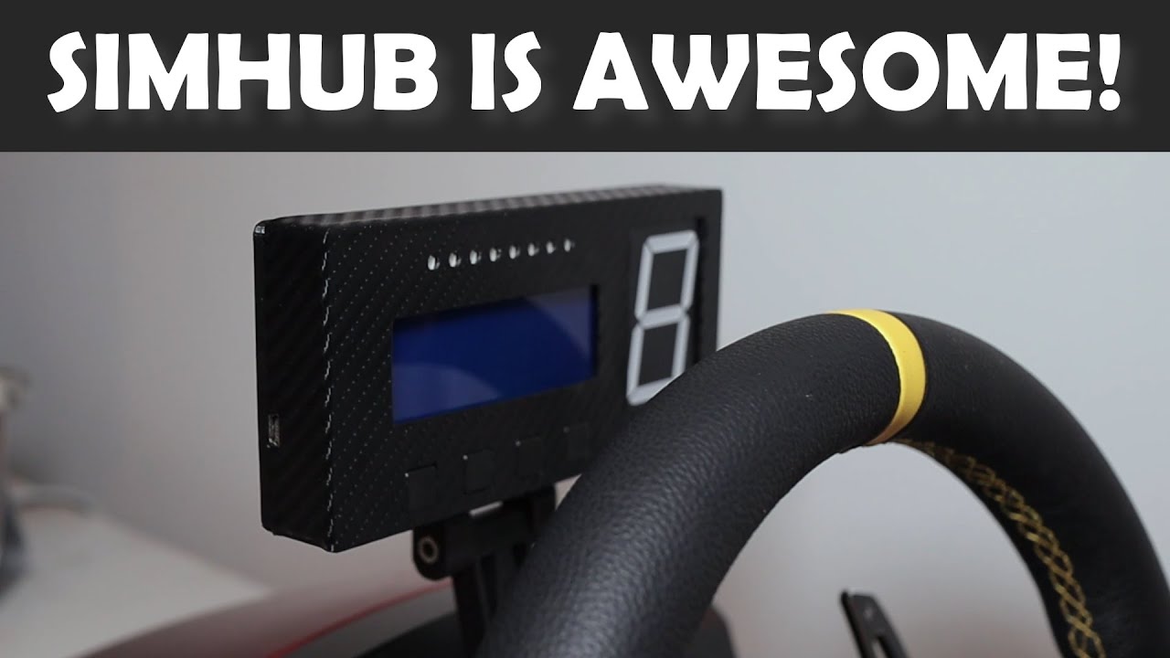
My first attempt on making a SimHub dash with some of the finding I learned while designing it.
Huge thanks to Bryan Young for inspiration and help on this project: https://www.youtube.com/channel/UCdhNcwXBpjyNi5EShDhR7IA
If you like my designs consider a small tip: https://paypal.me/PeterMakesThings?locale.x=en_GB
Join me on Facebook: https:...
elder hare
too many initializer values
class StripSettings
{
    private:
        uint8_t m_Pattern_Color_Gradient_Palette_Buffer[256];
    public:
        StripSettings()
        {
            m_Pattern_Color_Gradient_Palette_Buffer[256] = { 0, 255, 0, 0, 255, 0, 255, 0 };
        }
};
Why?
north stream
Drop the [256] from the initialization line
green thunder
green thunder
Hello! I have a couple of questions about using the DMA NeoPixel functionality, ...
So it does in fact seem that DMA is possible on the QT PY. Though my understanding is still quite limited, I noticed that many other boards allow the use of the MOSI pin for NeoPixel DMA, with the caveat that you couldn't use SPI anymore. After digging around in the ZeroDMA and the NeoPixel_ZeroDMA code for a bit, as well as the 'variant.h' file for QT PY in the core, I figured out that I could modify the 'pins.h' file in the NeoPixel_ZeroDMA library to add a definition for the QT PY. So, I added:
#if defined(ADAFRUIT_QTPY_M0) &sercom2, SERCOM2, SERCOM2_DMAC_ID_TX, 10, SPI_PAD_2_SCK_3, PIO_SERCOM_ALT, #endif
and it worked!
There may be other pin/sercom combinations possible that would not require giving up SPI, but at the moment I still haven't quite pieced together how to figure that out. I'm not entirely confident that I've done the correct thing here, but it does seem very promising.
gilded swift
@green thunder as far as I am aware, SPI can be assigned on a few different pins for the samd21e18a
Which is what is on the qt py
So technically you could change the pins assigned for SPI as needed for DMA
I believe the UART pins also should support DMA as well
green thunder
@gilded swift I know that other pins could probably be used, but due to my limited knowledge of samd21 processors and after reading the comments at the top of https://github.com/adafruit/Adafruit_NeoPixel_ZeroDMA/blob/master/pins.h, I'm not entirely sure how to figure out which pins should be used lol. It seems like there is probably some "ideal" combination of pins/sercoms per board, but at the moment I have no idea what the best way to figure out what that would be.
gilded swift
Well, if ya ever need help making a custom variant, I can probably help 🙂
green thunder
That would be most appreciated! 🙂
I'm still digging around trying to understand how all of this fits together, but ultimately I'd like to add (or help add) official support for DMA NeoPixels on QT PY. I'm going to continue just kinda poking around for a bit, but if you have any advice on where I could find more information specifically about why the choices were made in 'pins.h' that would be really helpful. Also, would doing this require modifying the variant.h/cpp files in the core for QT PY?
green thunder
Upon further exploration, it seems there are a couple of other pins that can be used by NeoPixel_ZeroDMA on the QT PY, for a total of 3: A6(TX), SDA(D4), and A10(MOSI). Of course, because the NeoPixels will be taking up a critical output pin, that means in each case you'd have to sacrifice UART, I2C, or SPI capable pins, respectively. I think this would be an acceptable tradeoff to make personally for the ability to have zero-cpu NeoPixel driving.
loud horizon
No, I uploaded the original code
two 10 segment led's, with ground pin on each side to a nano
one ledkeeps flashing
pine bramble
@green thunder Yeah but you're pushing the qt py paradigm way out of its niche.
You can squeeze a few more pins out of the SeeSaw and save a buck or two.
(ATSAM09D iirc)
green thunder
It's not so much that I'm trying to drive a lot of NeoPixels, or do anything like what NeoPXL8 is trying to do. Mainly I just want to e.g. be able to use NeoPixels and use an IR Receiver, or a servo
Neither one of those things seem outside of it's niche to me
pine bramble
What she gave you eleven pins on that qt py? (I had no idea; I overlooked it).
green thunder
yeah 11 pins
pine bramble
Thats' pretty good especially in pins vs dollars to buy one. ;)
pine bramble
Generally Limor is pretty good at figuring out how to optimize for a given design pinout.
variant.cpp is what encapsulates that decision tree, iirc.
green thunder
I think she was here too! I can understand that perhaps she decided maybe it would simply just not be a good idea to allow DMA NeoPixels given the tradeoffs involved
pine bramble
well they gotta pay the rent, so it's germane to sell a lot of $6 boards in volume, which means pleasing the needs of the widest variety of likely buyers.
green thunder
ha that's a good point
stuck coral
Sorry Im trying to understand the issue, ZeroDMA should be using a SERCOM from the SAMD21
You should be able to use any sercom
pine bramble
So modify the lib not the variant.cpp for the core. ;)
stuck coral
Oh okay, I just had to read a little more, duh
green thunder
well, for my part, I might make the case that a) since I rarely need SPI on the QT PY, and b) since the tradeoff to use the MOSI pin on other boards already exists, that it might be nice to at least have the option for one DMA NeoPixel pin on the QT PY 😄
stuck coral
Yep, should be fairly simple to add in
green thunder
yeah @pine bramble that's what I did, it works great!
Added this to 'pins.h':
#if defined(ADAFRUIT_QTPY_M0) &sercom0, SERCOM0, SERCOM0_DMAC_ID_TX, A6, SPI_PAD_2_SCK_3, PIO_SERCOM_ALT, &sercom1, SERCOM1, SERCOM1_DMAC_ID_TX, SDA, SPI_PAD_0_SCK_1, PIO_SERCOM, &sercom2, SERCOM2, SERCOM2_DMAC_ID_TX, MOSI, SPI_PAD_2_SCK_3, PIO_SERCOM_ALT, #endif
pine bramble
I was able to easily upload a functional program to the original CPX crickit, treating it as an ItsyBitsyM0.
(ignoring its design use as an adjunct board; I made it the primary board).
green thunder
Ha that's awesome
pine bramble
It wasn't too bad, and I learned a lot about how the core code was written/designed, in doing it.
stuck coral
green thunder
yeah <@456226577798135808> that's what I did, it works great!
Could you make a pull request to the core fix it for the next guy?
pine bramble
I was pretty close to writing my own board support package for the crickit but I didn't follow through - was proof of concept.
loud horizon
Could anyone help me with this error message?
green thunder
@stuck coral I was actually in the process of looking into doing just that 😄
green thunder
right lol
I forked it, I'm gonna make the change in my fork and make a PR with a comment explaining the rationale
at least for pin A10
pine bramble
@loud horizon What do you got there, moose.
stuck coral
green thunder
I forked it, I'm gonna make the change in my fork and make a PR with a comment e...
Yep, no other way on github 😜
loud horizon
@loud horizon What do you got there, moose.
@pine bramble
One blinking light and lost hope
pine bramble
That is awesome dense colorful wiring!
I love it.
What's the target board? It looks pretty small.
 rough torrent
loud horizon
Could anyone help me with this error message?
rough torrent
loud horizon
Could anyone help me with this error message?
It's really hard reading the text, (next time, please copy the error messages and paste it directly in Discord. Also inclose it in backticks) but I think it's an upload error. Make sure that the Arduino is connected, appears as a COM port, and you can read the Serial.println stuff coming out of it.
stuck coral
AVRDude cannot connect to target
loud horizon
Arduino: 1.8.13 (Windows 10), Board: "Arduino Nano, ATmega328P"
Sketch uses 3024 bytes (9%) of program storage space. Maximum is 30720 bytes.
Global variables use 210 bytes (10%) of dynamic memory, leaving 1838 bytes for local variables. Maximum is 2048 bytes.
avrdude: stk500_recv(): programmer is not responding
avrdude: stk500_getsync() attempt 1 of 10: not in sync: resp=0x61
avrdude: stk500_recv(): programmer is not responding
avrdude: stk500_getsync() attempt 2 of 10: not in sync: resp=0x61
avrdude: stk500_recv(): programmer is not responding
avrdude: stk500_getsync() attempt 3 of 10: not in sync: resp=0x61
avrdude: stk500_recv(): programmer is not responding
avrdude: stk500_getsync() attempt 4 of 10: not in sync: resp=0x61
avrdude: stk500_recv(): programmer is not responding
avrdude: stk500_getsync() attempt 5 of 10: not in sync: resp=0x61
avrdude: stk500_recv(): programmer is not responding
avrdude: stk500_getsync() attempt 6 of 10: not in sync: resp=0x61
avrdude: stk500_recv(): programmer is not responding
avrdude: stk500_getsync() attempt 7 of 10: not in sync: resp=0x61
avrdude: stk500_recv(): programmer is not responding
avrdude: stk500_getsync() attempt 8 of 10: not in sync: resp=0x61
avrdude: stk500_recv(): programmer is not responding
avrdude: stk500_getsync() attempt 9 of 10: not in sync: resp=0x61
avrdude: stk500_recv(): programmer is not responding
avrdude: stk500_getsync() attempt 10 of 10: not in sync: resp=0x61
Problem uploading to board. See http://www.arduino.cc/en/Guide/Troubleshooting#upload for suggestions.
This report would have more information with
"Show verbose output during compilation"
option enabled in File -> Preferences.
pine bramble
alright so that's a 328p which does not have built-in USB.
It's talking to a bridge chip like CP2104.
Bodger said there's been at least three solutions to the bridge problem over the years.
loud horizon
what would that be?
stuck coral
Looks like windows 10 to me
loud horizon
windows 10
pine bramble
What's the exact target board called? Nano?
pine bramble
"I have an Arduino Nano (ATMega 328p-based) and am in Windows 10. Can't upload to the target; the IDE is using AVRdude but I get an error."
Something like that is your question, I think.
pine bramble
Yeah I am not familiar with Windows at all.
reef ravine
did you try "Nano | Old bootloader"?
loud horizon
ill try it
same message
Arduino: 1.8.13 (Windows 10), Board: "Arduino Nano, ATmega328P (Old Bootloader)"
Sketch uses 3024 bytes (9%) of program storage space. Maximum is 30720 bytes.
Global variables use 210 bytes (10%) of dynamic memory, leaving 1838 bytes for local variables. Maximum is 2048 bytes.
avrdude: stk500_recv(): programmer is not responding
avrdude: stk500_getsync() attempt 1 of 10: not in sync: resp=0x0b
avrdude: stk500_recv(): programmer is not responding
avrdude: stk500_getsync() attempt 2 of 10: not in sync: resp=0x0b
avrdude: stk500_recv(): programmer is not responding
avrdude: stk500_getsync() attempt 3 of 10: not in sync: resp=0x0b
avrdude: stk500_recv(): programmer is not responding
avrdude: stk500_getsync() attempt 4 of 10: not in sync: resp=0x0b
avrdude: stk500_recv(): programmer is not responding
avrdude: stk500_getsync() attempt 5 of 10: not in sync: resp=0x0b
avrdude: stk500_recv(): programmer is not responding
avrdude: stk500_getsync() attempt 6 of 10: not in sync: resp=0x0b
avrdude: stk500_recv(): programmer is not responding
avrdude: stk500_getsync() attempt 7 of 10: not in sync: resp=0x0b
avrdude: stk500_recv(): programmer is not responding
avrdude: stk500_getsync() attempt 8 of 10: not in sync: resp=0x0b
avrdude: stk500_recv(): programmer is not responding
avrdude: stk500_getsync() attempt 9 of 10: not in sync: resp=0x0b
avrdude: stk500_recv(): programmer is not responding
avrdude: stk500_getsync() attempt 10 of 10: not in sync: resp=0x0b
Problem uploading to board. See http://www.arduino.cc/en/Guide/Troubleshooting#upload for suggestions.
This report would have more information with
"Show verbose output during compilation"
option enabled in File -> Preferences.
reef ravine
did it upload before you wired it?
rough torrent
Well, not exactly the same message. The response is different.
reef ravine
if it's easy hook up the bare board to make sure you don't have a PC side issue
you may or may not need to flip off ATMEGA Old Bootloader
loud horizon
I'll try another nano and upload on the regular atmega
reef ravine
some need it - some don't
pine bramble
Yeah a known good board is a great differential diagnosis
loud horizon
Arduino: 1.8.13 (Windows 10), Board: "Arduino Nano, ATmega328P"
Sketch uses 3024 bytes (9%) of program storage space. Maximum is 30720 bytes.
Global variables use 210 bytes (10%) of dynamic memory, leaving 1838 bytes for local variables. Maximum is 2048 bytes.
An error occurred while uploading the sketch
This report would have more information with
"Show verbose output during compilation"
option enabled in File -> Preferences.
^from using a different nano
reef ravine
flip the boot loader
loud horizon
old one now?
reef ravine
yes
loud horizon
Arduino: 1.8.13 (Windows 10), Board: "Arduino Nano, ATmega328P (Old Bootloader)"
Sketch uses 3024 bytes (9%) of program storage space. Maximum is 30720 bytes.
Global variables use 210 bytes (10%) of dynamic memory, leaving 1838 bytes for local variables. Maximum is 2048 bytes.
An error occurred while uploading the sketch
This report would have more information with
"Show verbose output during compilation"
option enabled in File -> Preferences.
reef ravine
is it a power only USB cable?
loud horizon
im using my ti84 color edition cord
reef ravine
ok so long as it passes data from the TI to the PC ok
does it "bing" when you plug the new one in?
pine bramble
nice verb
pine bramble
So then this has been going on for hours, as that's the same result the OP had many hours ago.
Sounds like the target has not once received new, locally-authored firmware. Ever.
pine bramble
Unless I'm conflating two people, seems it's been a while.
reef ravine
common issue 🙂
pine bramble
I really am going to buy an AVR within 30 days from now. You read about it here, first.
sniper's got me convinced to go with 32u4 rather than 328p
pine bramble
I'm also gonna get one of those fancy new Adafruit SPI debugging doo-dads with the TFT display.
loud horizon
I got a ws2812 led to work on my simhub display for rev lights on the same type of nano
pine bramble
I think I decided on ItsyBitsy, 5V logic, 16 MHz 32u4 to be compatible (the other Itsy option is 3.3v at 8 MHz).
loud horizon
it makes the usb cable noise when I plug it in
pine bramble
SPIDriver by Excamera Labs
http://adafru.it/4268
loud horizon
there's com5 and com8 to choose from
reef ravine
which shows up as an ATMEGA?
pine bramble
I want to be maximally compatible with the people I'm trying to help (people I have not met as of 31 Dec 2020, in the Arduino Discord).
loud horizon
pine bramble
I'm tired of saying "I don't know a thing about AVR sorry" lol