#help-with-arduino
1 messages · Page 49 of 1
 north stream
 safe shell
Well, that's interesting. All of my Arduino-developed ESP8266 devices (which are usually very stable running code from 2017, some have been running continuously for almost a year) stopped working at the same time early this morning. Ruled out Wi-Fi and local network issues. ESP32s running almost identical code are checking in with the server just fine, as are CircuitPython boards. I think it's HTTPS/TLS-related... either something expired, or maybe the server stopped supporting the encryption algorithm.
north stream
That is intriguing, and I agree with your analysis.
safe shell
So now I either need to (for about a dozen and a half devices): re-create the old dev environment (same code with updated boards and libs won't compile - deprecated HTTPS lib among other things); re-code 8266 with new secure client; migrate to ESP32, or; migrate to CircuitPython+Airlift.
And of course this happens right before I'm traveling.
north stream
Because of course it does, that's die Tücke des Objekts (the general cussedness of things)
safe shell
LOL, interesting reference 🙂
 bleak mirage
Does anyone have any experience with Firmata?
I want to be able to write to a DAC using Python but can't figure out how to do i2c communication with Firmata. Can only find stuff for reading and writing digital/analog pins.
north stream
I've played with Firmata, but I haven't tried I2C either
 vast cosmos
which firmata library are you using?
and if we are ante'ing up here, i'll raise one: does anyone here have any experience with SPI using DMA?
..particularly on STM32 HAL ...(quickly glances at the channel name, hopes nobody else notices too)
since we now have an STM32 board in the adafruit library, what objections would there be to hosting an #help-with-stm32cube channel here on this discord?
(and if i recall, more stm32-based adafruit boards coming down the pike soon too)
not to mention, even the newest beefy Portenta H7 is a dual-STM32-core being developed by.... wait for it... ....arduino
who do i contact for channel creation requests?
 cedar mountain
I've done STM32 SPI DMA drivers before, but it was a while ago and I don't have access to the code any more...
vast cosmos
well i have more of an STM32 SPI protocol implementation question: do you know if it is safe to change the SPI baud rate prescalar dynamically at runtime tp property communicate with multiple slaves with each their own max clock frequency
 burnt island
I believe so. It looks like that's what the SPIDevice class in CircuitPython.
cedar mountain
I believe so too, though you may need to temporarily disable the SPI peripheral to do it reliably.
burnt island
the other devices should be ignoring MOSI when it isn't selected so they shouldn't even notice that the baud rate changes
bleak mirage
Yeah I'm also finding STM32cube to be a pain
 burnt sluice
Hey. I have an Itsy Bitsy M4 I'm trying to program, but when I connect it to a USB port on my Mac (running Catalina), I get a steady purple light on the M4, and nothing drive shows up on my Mac. Also, I can't upload sketches. It can't find anything on the port.
An error occurred while uploading the sketch
No device found on cu.usbmodem14201
Pressing reset on the device lights up a red led briefly, but nothing else happens. Pressing reset twice moves into bootloader mode, but nothing else.
Okay. Tried pressing reset twice again and it did something different. (must have done it faster?)
Purple changed to green, drive (ITSYM4BOOT) appeared, and I can access the bootloader now.
Pressing reset again takes me back to purple. In neither state can I upload sketches.
burnt sluice
I made sure my bootloader was updated to 3.7.0. Still can't upload sketches.
 pine bramble
Did you try using another USB port on your computer?
Something in the operating system may be claiming the USB port. Could try booting from a cold start (power off, not 'sleeping').
@vast cosmos @bleak mirage dfu-util works for me.
burnt sluice
I just figured it out a few minutes ago.
pine bramble
I am deathly afraid to upgrade stm32duino as it was annoying to get dfu-util and Arduino IDE to work well together.
burnt sluice
I have to put the M4 into bootloader mode, and from there I can upload scripts.
pine bramble
@burnt sluice If the board is dead the red LED will no longer 'breath' in bootloader mode.
burnt sluice
I didn't think it was working because I was trying to use some external components, and they weren't functioning because I didn't have an external power source powering them. (This is mounted on a custom PCB, and while the individual components were receiving a bit of power from the board, one component was not, and it was the lynchpin.)
Once I added the external power source, the LED strips started working. (clock and data paths were going through some level shifters that were not getting power)
I figured it out when I changed the LED setup to just use the onboard LED, and it worked.
pine bramble
I miss more of those gotchas than I used to, but the solution is also more obvious when I do notice it. ;)
 mortal ferry
Does anyone on here use Sublime Text 3 with Arduino? bonus points if you use a Teensy
I'm debating using the Stino package but I'm worried about how much work it'll take for it to cooperate with the Teensy loader.
vast cosmos
yep, i use all 3 religiously @mortal ferry
but the only integration among them i use is alt+tab 🙃
mortal ferry
Lol
vast cosmos
if you havent tried using the official arduino-cli yet, i do recommend it. it will certainly make communicating sublime->arduino 1000x easier
mortal ferry
My only issue with that is that Arduino does not appear to ever update from file, if it is changed in another IDE. I imagine the CLI is used to get around that?
vast cosmos
you need to select the "external IDE" option in arduino preferences
mortal ferry
I was concerned I'd revert changes to my files, if tried to use the Arduino IDE. And I don't want to go opening it and closing it every time I flash
I see. What do I use the CLI for then?
vast cosmos
so that you dont have to use the arduino GUI. you can simply invoke the build and the flash from command line (and thus from a custom sublime "build system" i.e. bash script)
mortal ferry
That's what I figured. So the external IDE option is just for those who want to keep using the GUI
Thanks for the advice! I will investigate.
vast cosmos
well the external IDE fixes that issue you noticed about it not reloading from file
it will refresh from file everytime it gains focus
mortal ferry
Right, I getcha. A CLI is definitely more convenient for me though.
vast cosmos
same for me. if youre comfortable with modern CLIs it should be immediately intuitive. inline help with every sub-command too
vast cosmos
boy i hope all of this work im doing to optimize performance with my SPI TFT display wont all be for naught once I get to a stopping point and start retrofitting DMA into the mix
is DMA something you should really have architected into the software up-front? or can it be relatively straight-forward to implement (either by replacing existing code, or by adding as a feature option) after all graphics primitives over SPI have been defined?
cedar mountain
Just my opinion, but I've found it to be about 80% okay as an after-the-fact performance enhancement, and 20% headaches with questions of who owns memory and for how long.
A twist particularly with STM32 processors is that you sometimes run into DMA channel contention, where you need to only use SPI2 instead of SPI3 to avoid conflicting with UART1, etc. Similar to pin-assignment conflicts, these restrictions can be important to know about early in the design.
vast cosmos
im using STM32G4, which has a little different different SPI implementation
 potent ferry
Hi guys, i am having issues with arduino due and the i2c
Ooops, no BNO055 1 detected ... Check your wiring or I2C ADDR!
I am not having issues with the same sensor and its use with the mega though
is there any solution for the due for this?
tx
 fluid wagon
Is there anything else on the i2c bus?
 surreal pawn
which pins are you using for i2c? did you get them swapped?
looks like 20 is SDA and 21 is SCL on Due and mega 2560 which doesn't match the uno pinout
 red steeple
Hi, i have installed Arduino IDE 1.8.10 on an Raspberry Pi 4 under Buster with the latest Updates! I have installed the latest Arduino SAMD From Board Manager! When i install the latest Adafruit SAMD from Board Manager, then i always get Compile Errors with the Blink-Sketch! If i use a older Version of Adafruit SAMD it works. It look like a Problem with the path, because it is looking for a arduino15 folder, which does not exist on the pi. The Problem with the older Version of Adafruit SAMD is that i get compiling errors with the tensorflow examples. The arcadia examples are working! Many thanks for help!
potent ferry
20 sda and 21 scl. It deems they match on the due and mega
i am sure i did not swap them
 fair reef
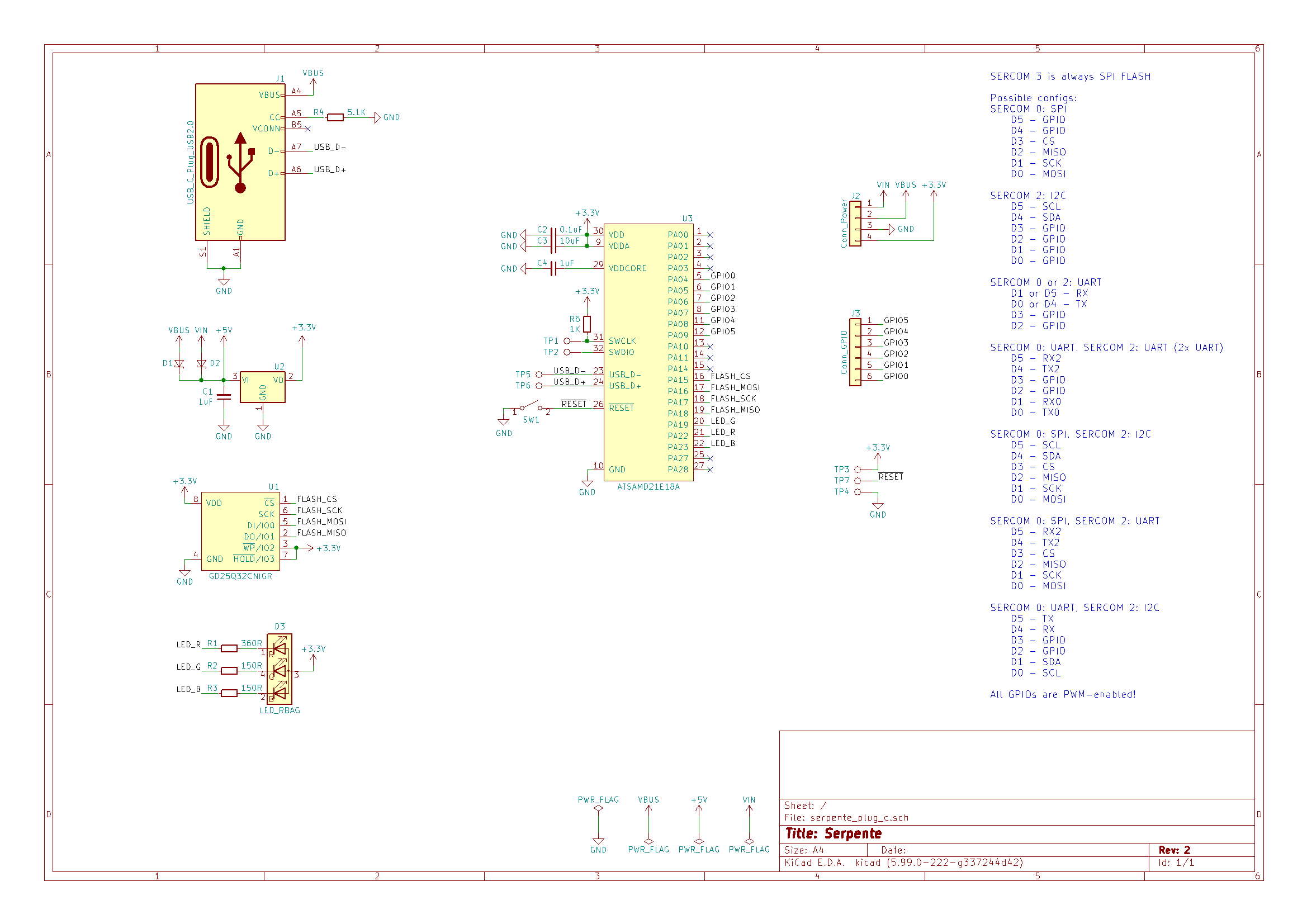
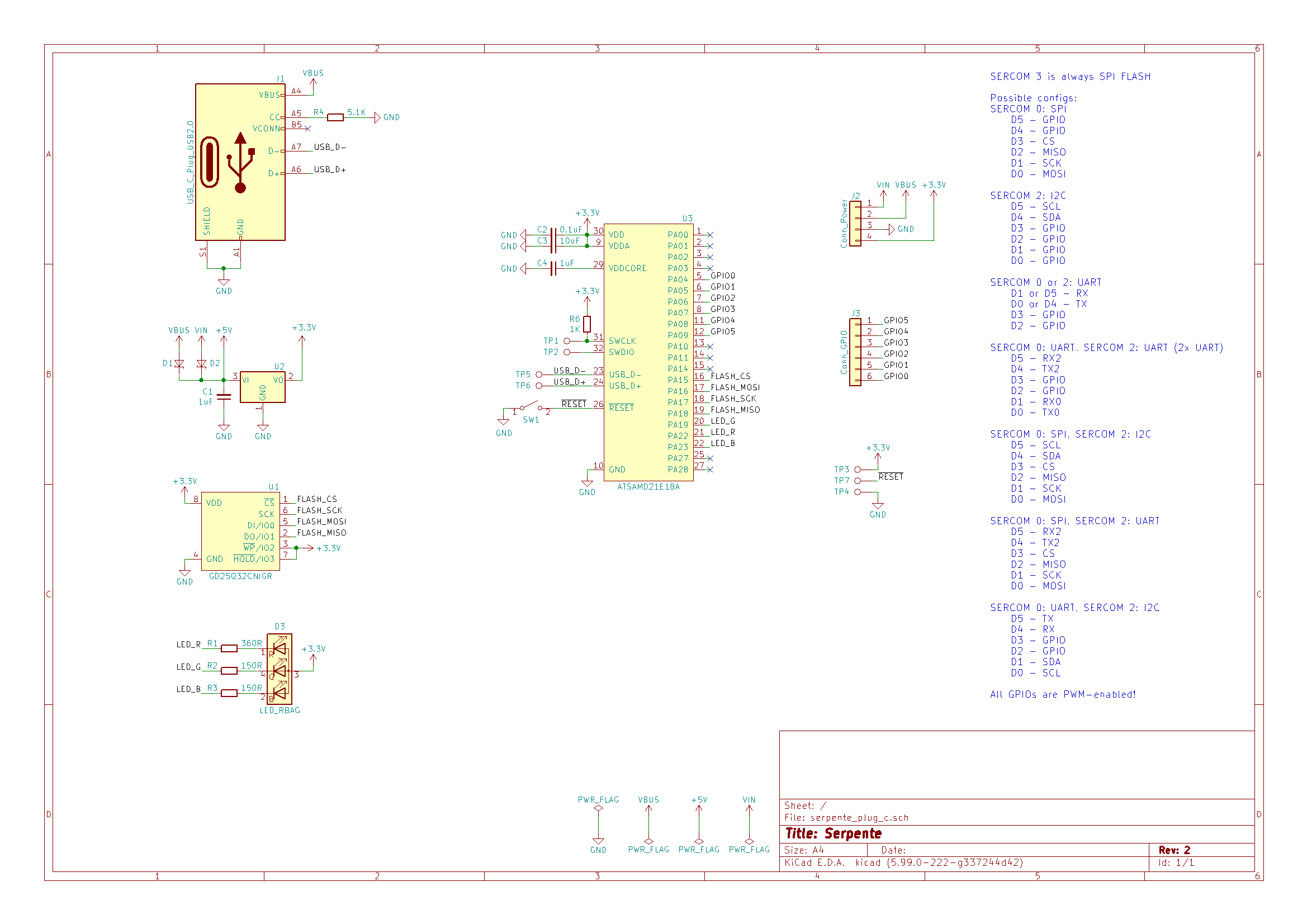
I can't figure out how to construct the Adafruit_FlashTransport_SPI or Adafruit_FlashTransport_QSPI classes for the Serpente R2 (and don't know which I need)
Its pinout shows 4 SPI pins, but I can't find how to construct the class with that.
https://serpente.solder.party/r2/schematics_plug_c.png
https://github.com/adafruit/Adafruit_SPIFlash/blob/master/examples/SdFat_ReadWrite/SdFat_ReadWrite.ino
https://learn.adafruit.com/adafruit-feather-m0-express-designed-for-circuit-python-circuitpython/using-spi-flash
I used this to get the libraries set up
I tried using pin 16 as SlaveSelect but I think it stopped USB serial working, idk. It was absolutely refusing to do USB Serial, on two different machines, when I did that.

GitHub
Contribute to adafruit/Adafruit_SPIFlash development by creating an account on GitHub.

Adafruit Learning System
Get running faster than ever with the first Adafruit Express board
 coral bolt
Howdy
Total noob here. Not totally sure I'm in the right place but here's my problem.
I have a Trinket M0 5V I'm trying to set up for use. I can not get the CIRCUITPY drive to appear. Running Windows 10 (its had all its shots).
I do hear the USB device sound when I connect and reset the trinket. I can also see it under Devices and Printers so I'm pretty sure Windows knows its connected
surreal pawn
there isnt a trinket m0 that's 5v
https://www.adafruit.com/product/1501 is an attiny85 and can't run circuitpython

Deprecation Warning: The Trinket bit-bang USB technique it uses doesn't work as well as it did in 2014, many modern computers won't work well. So while we still carry the Trinket so ...
coral bolt
Is that one Arduino IDE only?
surreal pawn
I'd expect so but haven't read the adafruit learning system page yet
coral bolt
got it. I think I was reading about the 3V one I had for another project
I'll give that startup tutorial a shot
Thanks!
surreal pawn
the trinket 3v is also attiny85 and can't run circuit python
coral bolt
thanks! appreciate the help
 upbeat kernel
Hi everyone! i'm working on this project : https://www.hackster.io/rundhall/infinity-mirror-wall-clock-in-ikea-picture-frame-700125 . the program was made with a esp8266 in mind but the arduino IDE give me that message : "WARNING: library Timezone claims to run on avr architecture(s) and may be incompatible with your current board which runs on esp8266 architecture(s)" . Is there a way to fix this?

Hackster.io
I built an RGB LED wall clock with internet synchronization (ESP8266) and combined it with an infinity mirror. By Rundhall.
 fierce aurora
I'm trying to connect an Arduino to my MacBook running Catalina. It's not showing up as one of the /dev/tty or /dev/cu ports. Before I go into all the details of what I've tried let me ask a simple question: is this a known issue? Are other's having problems with Arduino and Catalina?
 odd fjord
@fallen linden I'm not having any problems with Arduino and Catalina 10.15.2 (once I got past the initial security startup issues when I moved to Catalina)
 acoustic nebula
I also am running on Catalina. No USB issues, but I had to give permission for the IDE to run and access files
fierce aurora
Thanks for the replies. Are you folks using the SiLabs driver? Is that still required? I've tried with and without it. (FYI one of these MacBooks I've used for extensive arduino work in the past, pre Catalina, using that driver. But now I'm not 100% sure it's even installing. I expected that I'd have to bless it via the "Security/Privacy" control panel, but it takes no notice of this driver install.) I'm kinda stumped.
FYI the IDE seems to be running just fine. It completes compiles without complaint. But none of the boards I've tried will appear in the ports list.
odd fjord
@fierce aurora it's been so long since I installed any drivers, I don't recall if it is still there -- How can I check?
I do have SiLabsUSBDriver.kext in /Library/Extensions -- it's been there a long time...
When I connect an ESP8266 to my Mac it shows up as tty.SLAB_USBtoUART
but an Arduino UNO shows up as tty.usbmodem1424201
What board(s) are you trying to access?
fierce aurora
@odd fjord Thanks. What you're seeing is consistent with what I've seen when successfully connecting Arduinos in the past.
I just looked and I do see the SiLabsUSBDriver.kext on the older macbook. I do not see it on the newer macbook pro, but that's not surprising as I've been installing and uninstalling to try and isolate this.
I'm trying some more things now. I'll report what I find.
odd fjord
Good luck!
fair reef
Where can I best ask about how to configure Adafruit SPIFlash for the Serpente R2?
It's similar to the M0 Express, I think
odd fjord
@fair reef using Arduino or CircuitPython?
fair reef
Arduino
odd fjord
this is the place -- hopefully someone here to help -- not me, though 😉
fair reef
I did ask yesterday. How do I respectfully keep it visible? 😅
odd fjord
just ask again -- if it's been a day with no response, it's ok to ask again, weekends and holidays can be slow ...
fair reef
Alright. I'll wait until it's been 24h at leeeeast 😆
Thank you
 dull bison
Anyone can tell me why my LED keeps giving green color. I started code with pixel.clear(); and pixel.show(); and commented out the color defining ones. If i reupload this code it keeps my leds burn color of commented line
mortal ferry
I'm working on a graphics problem today and was wondering if anyone might be interested in helping me wrap my head around something:
 daring marsh
@fair reef you might be better off asking in #keyboards cause arturo182 hangs out there
mortal ferry
I'm trying to rotate this cube on a Teensy3.2. My approach so far has been a rotational transform approach, where I calculate whether each pixel is inside the bounds of the box by transforming it in reverse. But this takes 4 floating point multiplications, adding up to 4.2us per pixel, which ends up being pretty slow.
I found this approach, which avoids the multiplication: http://mathforum.org/library/drmath/view/54386.html but I'm really not getting the algorithm they list
surreal pawn
@dull bison on what hardware?
daring marsh
@mortal ferry 1) are you using float or double? double is incredibly slow
- can you use fixed point
 rocky igloo
@mortal ferry I think I'm following the post you linked to. How far along with it did you get? 😁
daring marsh
and are you using sinf/cosf
mortal ferry
I'm using float
@daring marsh and I have a sinf/cosf lookup table to avoid those
//transforms for rotated rectangle
int xshi = screenX - box_cen;
int yshi = screenY - box_cen;
int x2 = cos_lookup[boxThe]*(xshi) + sin_lookup[boxThe] * (yshi) + box_cen;
int y2 = -sin_lookup[boxThe]*(xshi) + cos_lookup[boxThe] * (yshi) + box_cen;

if (x2<box_max && x2>box_min && y2<box_max && y2>box_min) {
  p = BLUE;
} else {
  p = BLACK;
}
have you timed where the delay occurs
mortal ferry
yes, but not floating point mults and divs
@north stream
@elfin gate yeah it's literally the two lines calculating x2 and y2.
everything else is basically 0
On a 128x128 oled, they take a cumulative 69ms per frame, or 4.2us per calculation
420 cycles on a 96M Teensy. That seems like a lot for a processor with an FPU
rocky igloo
@mortal ferry What's the problem? Is it converting corner points to equations that define lines?
mortal ferry
It converts corners to lines, and then uses the property that a point must be on the "correct" side of each line in the polygon to be inside it
rocky igloo
Yes I understand how it works. What part are you having trouble with?
mortal ferry
I'm not totally understanding how the "correct" side of each line is determined
And if I use the included code for visual basic, I don't understand this line "ppx and ppy are in an array of points where (j) is 1 minus (i)"
rocky igloo
If you go around the square and define the endpoints of lines in order, the "correct" side will always have the same sign. Ie, if you're defining the line as connecting (x1,y1) with (x2,y2), define those points in the order you visit them going around the square.
Clockwise, all the points inside will have one sign (positive I think but it's trivial to test) and counterclockwise it'll be the opposite.
mortal ferry
How does one determine the correct sign at the start? Whether they should all be positive or negative?
Ah, I get you
Hmm, the trick is that I'll need to calculate the vertices of the rectangle, which I can do just one per loop, but I'll need to ensure they have that counterclockwise listing
rocky igloo
I think that's the gist of it. To define a line, you get to pick which is (x1,y1) and which is (x2,y2). If you're consistent about that, the sign for the test will be the same.
Rotation won't change the ordering of the vertices. Assuming you have the points in an array, that order should be ok.
mortal ferry
I have to make them using the center of the rectangle and the dimensions
but the order should stay consistent with that calculation. I'm having to brush up on all this trig haven't used it in a long time
rocky igloo
I've done graphics for a living and I've been a college math teacher. 😁 Ask away if you get stuck on anything.
mortal ferry
I see why it's so slow. I forgot that the FPU is optional on the Cortex M4, it actually doesn't have one :/
hence uber slow
north stream
Will an integer approximation suffice?
mortal ferry
Yeah I'm not going for precision at all here
rough rotated rectangle is fine
what would be the best way to achieve that? just a big multiplier on the sin output?
north stream
Yes, I think that was what LadyAda was getting at when she mentioned fixed point.
rocky igloo
For sure .The main thing is doing one integer multiply and an add and a compare per point.
The corners are insignificant. The pixel test is what matters.
mortal ferry
So in my lookup table should I just do cos_lookup[i] = cos(i_fl/57.2958)*65535, then divide down post multiplication?
stored as 16b
rocky igloo
Looks like that would work.
Sometimes you can notice a difference between rounding and truncating,
fluid wagon
Good afternoon all
is there a way to have Adafruit's WiFiNINA coexist with the Arduino WiFiNINA? or, is the Adafruit Version compatible with Arduino.cc boards?
mortal ferry
hmm something has gone very wrong
rocky igloo
Sounds like a good first step.
mortal ferry
Nope was just a cast issue! Working great now, super fast!!
man what a relief
thanks so much for your help @rocky igloo @north stream @daring marsh
daring marsh
@mortal ferry i have 'use' of a 3d cube renderer - if i can set the colors for each side...
is that possible with yr code
mortal ferry
3D cube renderer? Woof maybe at some point.
I'd definitely need a more generalized polygon function. I'm just using this for my fork of Uncannyeyes right now.
I assume you'd want that in full perspective and everything.
vast cosmos
its amazing the speedup ILI9341_t3 gains without even using DMA. im really struggling here trying to understand how
 hasty dawn
Using an Adafruit Feather M4 Express compatible with Arduino IDE (https://cdn-learn.adafruit.com/downloads/pdf/adafruit-feather-m4-express-atsamd51.pdf) Needing to write flash storage to store a string of data and then access that storage at a later time. With no EEPROM on the feather, what protocols are possible to use for this? Is flash read/write cycling going to be an immediate issue?
north stream
Should be good for 100k cycles, but be careful of partial page writes, which can do full page writes if you just change one byte.
 lost jetty
Does anyone have any code chunk examples that would add time setting functionality to an RTC clock sketch? Or a clock setting setup?
north stream
I found some clock setting software that embedded the time it was compiled and set the clock to that. I thought that was inelegant, so I used Firmata to let a host program send the time to a sketch. https://gitlab.com/bodger/plotclock

GitLab
My own version of software to set and operate the plotclock originally designed by Johannes Heberlein, AKA Joo.
lost jetty
I'm looking for the example sketch I used for the project... revisiting it because the clock time is off from actual time...
fierce aurora
following up on my questions/troubles of this morning... is it possible that i have a feather huzzah that is, for lack of a better word, "corrupting" the USB/serial port on my macbook?
mortal ferry
got a little demo going
@fierce aurora I've certainly had the drivers on my mac fail before. It's usually the only time I ever see my mac "crash" - happened two times this week, actually.
does restarting fix your problem?
 flat latch
owo!
 last breach
Hi! Does anyone have experience working with the Bluefruit 32u4 and Bluefruit control app?
fierce aurora
@mortal ferry Yes, in fact restarting is this ONLY thing I've found that gets the serial connection working again. But as of now I'm starting to suspect one particular huzzah board may be the problem. I have multiple boards here, and it seems that I can unplug/replug all of them with no problem, except for this one board. More testing to come.
acoustic nebula
check if it's a CH340 vs CP2112/4 issue
different USB->Serial chips with different drivers
odd fjord
the Huzzah uses a CP2104 USB-serial bridge. @fallen linden did you end up install thing the SILAB driver?
are you using the ESP8266 or ESP32 Huzzah?
@fallen linden ah - sorry -- I just read back further -- sounds like you have it working - in general. Just one board behaving badly. I have had issues with the CP2104 chip failing on ESP8266 feather Huzzahs in the past -- a few years ago now -- but in those cases, the chip went up in smoke 😦 .
some history, but as noted in the last post of this thread, a design change was made to hopefully have resolved this. https://forums.adafruit.com/viewtopic.php?f=57&t=116221&hilit=+cp2104
 fallen linden
@odd fjord and others... I have two seemingly identical huzzahs here. one works as expected. the other connects with the serial/usb port name of "/dev/tty.usbserial-017C83A0" which is not the expected name, and confuses the IDE (won't upload). Also, when this trouble huzzah is unplugged no other similar device can be connected until a reboot.
@acoustic nebula The two huzzahs appear identical. Is it possible that similar board models might have different serial chips?
odd fjord
That is a strange port name for an ESP8266 -- I have tried a few (esp8266 and ep32) and all come up with tty.SLAB_USBtoUART
on my esp8266 - the chip is near the reset button -- you can read SIL2104 on it
acoustic nebula
I thought you might be working with other brands of dev boards. From Adafruit, they should all be the same.
north stream
Mostly the same, the link jerryn posted states that the power supply wiring was changed in 2018 (although the schematic on the tutorial page is still the original one). They do, however, still use the same chips.
fallen linden
@acoustic nebula @north stream Thanks.
 upper rune
so lets say i have an array: int myArray[] = {} how would i append something to the array??
mortal ferry
@upper rune that is not a safe operation in C or C++, arrays in those languages are of a fixed size and cannot be expanded on the fly.
you could use something like a C++ vector, but in general, you tend not to have data structures that expand and contract like that in embedded programming. It's usually better to try and think of a different approach to the problem.
upper rune
ok
 mild elk
I wanted to build a small radio with oled screen. I wrote a code that initializes the radio chip, and then writes "Hello world" on the display. When I upload it though, I only get clicking in the headphones and no picture on screen. I worked out that display.print("Hello world"); is the line that causes problems. Any ideas what's wrong?
north stream
I'd first look at pin/bus contention
Then I'd look at memory issues (screen drivers often eat up a lot of memory)
pine bramble
Dude's, dudettes. I'm stuck with something and I have been busy with it for God knows how long. How do I read a string that an Arduino prints???
My program code:
void loop() {
  Serial.println("hello");
delay(5000);
}
I'm using Java.
north stream
You can use the serial monitor, or just open the serial port and read from that.
pine bramble
I have to send it to a Java app.
north stream
Can you have the Java app open the serial port and read it itself, or do you need middleware?
mild elk
@north stream the screen is connected properly, because when I comment out the radio code it works fine
Also I doubt there is memory issue, the IDE reports 50% RAM and FLASH free
north stream
I get that the screen is connected correctly, but perhaps it and the radio are competing for some particular resource.
pine bramble
I can do that. I tried it too, but the methods are so confusing. I get wrong output. I tried using the JSSC library
north stream
I'm not familiar with the JSSC library, but I'm guessing it's overkill. Just open the port as a file, then attach a stream to it and read from the stream.
import java.io.BufferedReader;
import java.io.FileReader;

BufferedReader in = new BufferedReader(new FileReader("/dev/usbserial1412"));
I tried that but I think I did it wrong
north stream
The only tricky part is setting the port speed, but there are ways around that.
Well, that, and dealing with handing the port off between your app and the Arduino IDE which also uses it to download code.
I'll admit I'm rusty on this (haven't played with it in a while), so I could well be omitting something important
A little poking around reveals that there's a javax.comm.SerialPort package that supports setting things like the port speed.
I haven't used it, however.
pine bramble
Tried all the libraries
north stream
That's one of the reasons I'm fond of low level approaches (like FileReader).
pine bramble
I could also save the values in a file, then read it with Java but I would like to have a direct connection
north stream
A direct connection seems like something worth doing.
 subtle tree
I'm struggling a little bit with some code and was hoping someone could take a look at it and see what I'm doing wrong. I'm trying to take a reading off of a salinity sensor, taking 15 readings, and averaging them and then printing the results to the serial monitor. At the moment I just have it hooked up to a photoresistor in place of the salinity sensor to make things easier to diagnose. Unfortunately I'm unable to get any readings from my serial monitor aside from "0.00", but can't figure out why. It's probably something easy but having stared at the code for over an hour I just need someone else to look at it and diagnose my stupidity.
int salinity_power_pin = 4; // Digital I/O pin, Global variable void setup() { Serial.begin(9600); pinMode (salinity_power_pin, OUTPUT); } void loop() { int salinity_input_pin = A3; // Analog input pin int n = 15; // number of readings to average float salinity; // Average reading is a float salinity = sensor_reading_ave(salinity_power_pin, salinity_input_pin, n); Serial.println (salinity); } // ------------------------------------------------- float sensor_reading_ave(int power_pin, int input_pin, int nave) { float ave, sum; digitalWrite(power_pin, HIGH); // Turn sensor on delay (100); // Wait to settle sum = 0.0; for (int i; i<=nave; i++) { sum += analogRead(input_pin); // Accumulate the sum delay(10); // Pause, briefly } digitalWrite(power_pin, LOW); // Turn sensor off ave = sum/float(nave); // Compute average return ave; }
cedar mountain
For what it's worth, the code looks sane to me. Do you have a multimeter or something to verify that your analog input is not actually 0?
subtle tree
I can run a completely different program that I used in the past to get analog reading from the photoresistor and that's pumping out sane values, so it's not my connection
The second I change the value for sum = 0.0; I start getting different values so I'm thinking it has something to do with that?
granted it's again just a repeated value and not fluctuating like one would expect with a photoresistor
surreal pawn
what's your circuit?
subtle tree
digital pin 4 treated as my input voltage, in series with resistor and photoresistor and analog pin 3 for a voltage divider with ground being the Arduino
I can take a picture if that doesn't make sense
surreal pawn
pin A3, or pin 3?
subtle tree
I think my issue is that it's not actually taking an analog reading and it's just adding 15 sum= values and then averaging that?
Pin A3
surreal pawn
your code looks ok but I don't have an arduino handy to try it on
subtle tree
No worries, even just taking a look at it and saying that it makes sense helps me a bit. Makes me feel less insane since from what I can tell it should function fine. The fact someone else thinks so too takes some stress off
Thank you c:
surreal pawn
@subtle tree this seems like what you described but doesn't make sense to me
More sensible analog voltage circuit
subtle tree
I had to change for (int i; i<=nave; i++) to for (int i=0; i<=nave; i++) and it worked
surreal pawn
I wish arduino had more warnings enabled by default. it'd catch stuff like that
huh, platformio doesn't catch that
well, the default build options don't but the "inspect" option does find it
cedar mountain
@subtle tree Oh, man... kicking myself for missing that. Good catch!
pine bramble
🌲
float sensor_reading_ave(int power_pin, int input_pin, int nave) {
// float ave, sum;
float ave = 0.0;
float sum = 0.0;
@subtle tree
Always initialize when you (define and) declare. Especially Arduino IDE coding environment. ;)
Yeah I totally missed the for (int i; .. business, as well.
I write that correctly, almost every time, but I've seen that happen before (recently) and should be keeping a sharper lookout for it. ;)
(again: always initialize when you declare ;)
pine bramble
🌤️
@red steeple it may be the path to the compiler. The full error log will be helpful - turn on all warnings and compile a blank sketch.
(see #hug-reports for origin of this thread ;)
basically you can download the github repository for the arduino core (for SAMD).
Check both open and closed Issues in that repository for hints on what's going on.
I use gitk here to review recent commits, when I get stuck for troubleshooting ideas.
The new compiler rejects a lot of code (and/or I've turned on additional warnings, lately ;)
So more orange messages seen. Could be the way I'm using the IDE (haven't in a few weeks, now, except briefly with well-trodden code I just wanted to tweak).
🛩️
@fair reef
I used this approach ('this' meaning, as follows!) to get the SPI flashROM working on the new STM32 board (early adopter):
https://github.com/wa1tnr/Cortex-Forth-STM32F4x/blob/master/Cortex-Forth-STM/src/flash_ops.cpp#L52
Basically the technique is to examine the source and create new #defines that weren't already provided.
pine bramble
variant.cpp always enumerates all pins in D0, D1, D2 .. order.
Cross-reference it with the CircuitPython version, if there's any confusion.
In my #define (in the termbin at nnzb there) I'm using the D0, D1, D2 type pin names (they're just integers; the D part is implied but isn't in the code, only in the comments).
This worked for a new board from Adafruit on a new chip architecture I'd never looked at, prior.
So to port from someone's outside SAMD21 board should be a cakewalk. ;)
fair reef
@pine bramble, hi, the approach you used no longer compiles, as far as I can tell:
no matching function for call to 'SPIClass::SPIClass(int, int, int, int)'
And I'm trying to use SPIFlash.pins() instead but I can't interpret the class definitions very well.
Thank you for all the material; I think I'll have the correct pin definitions for Serpente now. It's just configuring the code.
fallen linden
Finally seem to have this serial/usb port thing sorted out. Now that I can play around with this little variety of boards I have here I have this first observation: the feather LORA (M0?) seems MUCH faster than the feather Huzzah (ESP8266). !!!
burnt sluice
The Itsy Bitsy M4 has a 3V power output pin. Does that pin need to be enabled if not using USB power? (reference: https://learn.adafruit.com/introducing-adafruit-itsybitsy-m4/pinouts)
north stream
The enable pin has a pull-up resistor so it's enabled by default.
The 3V output pin is connected to the same regulator that powers the rest of the circuitry
burnt sluice
Thanks, @north stream.
pine bramble
@fair reef This compiles fairly cleanly (well enough to compile and upload to the target):
https://preview.tinyurl.com/tnr-dviba-42
which is the diff of:
https://github.com/wa1tnr/conversations/blob/master/arduino/hardware/serpente-core/samd/variants/serpente/variant.h#L124
I don't own serpente hardware so I was not able to test any of my ideas on the hardware itself.
[upstream] Source listed here:
https://github.com/wa1tnr/conversations/blob/master/arduino/0-Distribution.d/technoblogy/uri.txt
 hexed agate
Has anyone used the arduino SoftwareSerial Invert param successfully with RX data?
rx gives me gibberish, tx works fine, digital invert works, scope decodes also ,wondering if its a bug before I setup a test
 wraith current
@hexed agate I've used it to receive data from an ultimeter weather station at 2400 baud using a metro mini board
fair reef
@pine bramble,
thank you for all your time in this. I've tried this, and while it does compile, its fails to open the root dir:
https://gist.github.com/phunanon/01da2c5b2bb43ffcf8a1c00243e9275e
I just transplanted the #define's into there
 lusty bear
I'm facing this problem while trying 'sdfat_circuitpython' example code from 'Adafruit_SPIFlash' library. Can anybody help me fix this? I'm using Adafruit Feather M0 Basic by the way.
And for information. I already load the circuitpython .uf2 before running the sketch.
 north kelp
@lusty bear I'd also ask that in #help-with-circuitpython (but I know the example code is in Arduino). It may be that the M0 Basic doesn't have enough flash.
lusty bear
@north kelp Thanks for replying. That is a possible reason. Is it possible to turn M0 basic to M0 express by adding external flash? If it is is there any tutorial that I can follow? I'm asking this because the board are essentially the same, and I saw somewhere that someone hack the Trinket M0 and change it to Trinket M0 express by adding an external flash.
I want to try doing this "upgrade" but I dont know how
north kelp
That would likely be difficult. I'd suggest just getting an M0 Express.
lusty bear
unfortunately I cant because I dont have the money to get M0 Express, and I kind of have a dateline in the project that I'm trying to develop. Anyway thanks for replying. If you have any idea or suggestion please do tell. Thank you👍
north kelp
@lusty bear A less expensive option might be the ItsyBitsy M0 Express:
https://www.adafruit.com/product/3727
What's smaller than a Feather but larger than a Trinket? It's an Adafruit ItsyBitsy M0 Express! Small, powerful, with a rockin' ATSAMD21 Cortex M0 processor running at 48 MHz - ...
What's your goal with the flash?
How much storage do you need?
Does it need to be accessible as a drive on a PC?
Are you just using it for logging?
lusty bear
My goal is to store a few small audio file and play it through the DAC pin of the M0. I have not consider how much I needed yet probably 2MB++. It doesnt have to be but it will be easier if it is accessible. Im using it to store audio file and open it to play the speech recorded.
yeah I have already consider the itsybitsy, but unfortunately the shipping will be too late for me
flat latch
.oO( Wonder if there are any .mod players for arduino. 😉 )
pine bramble
Hey everybody I am looking for tutorials on how to setup things like a UART or SPI or digitalWrite etc etc.
By that I mean low level stuff. Register stuff. I understand things like arduino make it easier to use.
I did look for some libraries from the arduino code. Also I have barebone Atmel328p chip with some hardware components to flash it.
I used Atmel Studio to flash it.
But I need some cool tutorials or a course that explains stuff about datasheets and on how to program stuff like this.
And by stuff like this I mean. Starting from sratch to learn on how to develop and code "drivers", drivers like writing to EEPROM or setting up SPI
Would be awesome if someone knew a good course or tutorial.
Most of the stuff on the internet makes it easier to program. But I want to learn more about under the hood.
I am a 4th year electrical engineer so yeah I know a bit of stuff.
wraith current
@pine bramble https://www.avrfreaks.net/forums/tutorials
AVR Freaks
pine bramble
@fair reef The opposite approach will bring things closer: remove anything you possibly can from the .ino file .. and locate it in some other file.
What I did was system level (to add a second SPI interface, for the flashROM) and it belongs there, at system level (in variant.h only; that's why I put it there).
With the work on the STM I made one or two quick changes and got away with using a #define .. I had the hardware on hand to test and prove the approach, but it's still not complete, as it was a dodge (I just didn't want to do it correctly as that would have been more time consuming).
All that said I'm using my skill of 'testing well' (when I take a test in school, I do very well as I 'test well').
I don't understand the problem very well, but I understand how language elements are used to address the problem, and I know many of the locations where different sorts of problems get coded to.
Also the 'little endian' warnings tell me something isn't quite installed correctly (anymore).
I tested against unmodified application code (that makes use of the flashROM) meant for an Adafruit target board, but using the serpente board definition.
The commented stuff is correct already.
The highlighted line is the one meant to be used, and it is used. You can guarantee it'll be used by reorganizing the rest of the code.
 past portal
Before I spend a lot time digging into this, is there some obvious reason the Metro M4 wouldn't be usable as an Arduino ISP? I want to use the same shield I have been using with the Uno (target is programming ATTiny85's).
pine bramble
@wraith current thanks bro.
north stream
@past portal You may have voltage level issues if you're running the ATtiny at 5V: the M4 is only 3.3V. Other than that, the M4 should be able to execute the programming algorithm, but if you're using the AVR version of the code, the timing/port manipulation may require some tweaking.
past portal
thx I'll look into it. The sketch looks portable enough, but I have to think the digital outputs being only 5V is gonna mess up the programming sequence. I'll try to level-shift the Metro M4's ISP-relevant outputs up to the USB-supplied 5V.
 tight axle
Has anybody used the nrf52 arduino bluetooth library as a central scanner for other devices?
I'm attempting to use the example here:
To detect if my iPhone or iPad are within sensing distance of a Circuit Playground Bluefruit. I get MAC addresses back in the scan, but none of them appear to be any of the Apple devices I've tested around. I'm beginning to wonder if there is something manufacturer specific or some kind of behavior I'm not picking up on?
GitHub
Adafruit code for the Nordic nRF52 BLE SoC on Arduino - adafruit/Adafruit_nRF52_Arduino
surreal pawn

Information Security Stack Exchange
Companies, governments, etc. can track Bluetooth and WiFi network scans passively by looking at a same MAC address over space and time (Bluetooth/WiFi Identity tracking in public spaces - How to di...
@tight axle ^
tight axle
Well, that's good, but I'm going to have to rethink my approach now. Was wanting to change some LED colors when I got close to the device, but I couldn't see the name in the scan so was going for MAC.....hmm
north kelp
@tight axle It's a bit complex, but possible, if you compile and load a custom iOS app onto your iPhones/iPads/iPods. Here are some resources:
https://learn.adafruit.com/crack-the-code
https://learn.adafruit.com/adafruit-circuit-playground-bluefruit/advertising-beacon

Adafruit Learning System
Learn how to make a Bluetooth Low Energy App for iOS using Swift.

Adafruit Learning System
Circuit Playground Bluefruit: Everything amazing about Circuit Playground, now with the power of Bluetooth!
An iOS app implementing Apple's iBeacon functionality can be woken up by a nearby BLE device advertising with the iBeacon standard. It's probably possible to then have that iOS app send a message to the CPB; I'd try using BLEUart to start.
https://learn.adafruit.com/adafruit-circuit-playground-bluefruit/ble-uart-controller
Adafruit Learning System
Circuit Playground Bluefruit: Everything amazing about Circuit Playground, now with the power of Bluetooth!
surreal pawn
eh
 calm crown
 noble fjord
i am trying to be able to see which led is blinking on and off can some one help with it i got the blink code just right but i need tell when it blinking off and on threw searile montor just not sure how to write in code i need to tell what two leds are doing if posable
 noble fjord
were
odd fjord
@fluid wagon The only project I have played with that uses arcada is https://github.com/adafruit/Adafruit_Learning_System_Guides/tree/master/M4_Eyes I have not dug into it, but there may be useful examples in it.
fluid wagon
Well, I tried out the pybadge test that uses it
However, it is unable to see my feather (it apparently detects wireless)
my airlift featherwing
Now, I tested the featherwing using wifinina and it works just fine on the pybadge
so I am confused 😉
My guess, is that arcada is looking for an ESP32 set up like on a metro m4 airlift, but, I have no leads. The docs for arcada simply say arcada.HasWiFi is checking for it, and it is failing in this case.
Wanted to make sure I wasn't missing anything before I asked in a bug report on arcada
Note: I even went and upgraded the ESP32 firmware on the featherwing to the latest
odd fjord
hmm -- I see that for the Pyportal Titano it pulls in WIFININA, but not for the PyBadge. https://github.com/adafruit/Adafruit_Arcada/blob/master/Boards/Adafruit_Arcada_PyPortalTitano.h#L3
and it sets it up here https://github.com/adafruit/Adafruit_Arcada/blob/master/Adafruit_Arcada.cpp#L155
perhaps you just have to #include <WiFiNINA.h>
it's not clear to me, but you've worked with this -- are you telling it where to find your airlift -- somehow it has to get to here https://github.com/adafruit/WiFiNINA/blob/master/src/WiFi.h#L265
excuse me if I'm telling you things you already know...
fluid wagon
Not at all I appreciate the help
Let me try adding the WiFiNINA library
Honestly I figured since Arcada was looking for wifi it pulled it in under the hood
Since this seems to be a library similar to that pyportal one that abstracts all the things away
Nope, still failed
And dang, adding a speaker to the pybadge makes it loud 😉
odd fjord
at first glance it looks like it does that for the PyPortal but not for the PyBadge -- somehow needs to be made aware its there...
somehow you need to tell it what pins the airlift is using.
fluid wagon
yeah, that just occurred to me
let me copy in the pin defs for the featherwing
Ok, so I copied in the wifinina pin defintions
and that did not work
Unfortunately, arcada abstracts away the Wifi config it appears
odd fjord
😦
fluid wagon
if (!arcada.hasWiFi()) { Serial.println("AirLift WiFi module not found"); arcada.display->setTextColor(ARCADA_YELLOW); arcada.display->println("WiFi FAILED"); } else { Serial.println("AirLift WiFi module found!"); arcada.display->setTextColor(ARCADA_GREEN); arcada.display->println("WiFi OK!"); }
that is the relevant code
and all I see regarding it
it is checking if it is present, but the check fails
odd fjord
I think that ties back to here https://github.com/adafruit/Adafruit_Arcada/blob/master/Adafruit_Arcada.cpp#L155
what code are you trying to run on the pybadge-- do you have a link to it?
fluid wagon
It is the demo from the arcada library
in the examples
the pybadge board test
So, I defined SPIWIFI
I added
#define SPIWIFI SPI // The SPI port #define SPIWIFI_SS 13 // Chip select pin #define ESP32_RESETN 12 // Reset pin #define SPIWIFI_ACK 11 // a.k.a BUSY or READY pin #define ESP32_GPIO0 -1
And my defines are before where the arcada object is created.
fluid wagon
Yes
However, I verified on the pybadge that the airlift works
by using the wifinina scan networks sketch
(with the correct pin defs)
So, I know the device functions
I mean, technically, for this sketch it doesn't REALLY matter. but, if I want to work with Arcada in the future, I need to know it works with all the hardware 😉
odd fjord
I'm wondering if you set up WIFININA independently --the it will pass the WIFI.Status() test ... trying....
ah -- just ralozed I have the Arduino WifiNina lib installed not Adafruit fork -- re installing
fluid wagon
Yeah, I've done that more than once
So, I declared wifi.setpins in the setup, and, included the pin defs for the airlift featherwing, still no joy
 unborn gyro
hi, i'm here to ask a question about a wemos D1 mini and a dht11 on blynk if someone can help me
north stream
Some people know about the D1, some people know about the DHT11, and some people know about Blynk. Depending on where your problem is, some folks might be more able to help than others. However, without knowing what the problem is, someone seeing that description might overlook it if they don't know about all three of those.
unborn gyro
i'm trying to put a sensor dht11 on blynk with a di mini but i don't found a real tuto or explanation to code the D1, i'm a begginner so ... i'ts hard to found were is the problem and how to solve it
odd fjord
@fluid wagon I am baffled as to why the arcada test for .hasWifFi is failing but looking at the code, Its not clear why it even bothers to check since it never uses WiFi. I can connect to t my AP fine by independently configuring Wifi and then let arcada do it's thing. I would like to understand why the test fails, but at least all the pieces work... Is there something that is making WiFI.status() within the arcada code not the same scope as WiFi.status() from the main program? It passes in the main program. but fails in the arcada check....
north stream
It seems like you have three different issues, and it's probably better to solve them one at a time than attempt to address all of them at once. One issue is "how to code the D1", one is "how to talk to the DHT11 from the D1", and one is "how to integrate Blynk with the D1".
unborn gyro
@north stream i'm using this code https://github.com/beegee-tokyo/DHTesp/blob/master/examples/DHT_ESP8266/DHT_ESP8266.ino to use the DHTesp.h, now, i have to make it connected on my wifi and send the data on blynk

GitHub
Optimized DHT library for ESP32/ESP8266 using Arduino framework - beegee-tokyo/DHTesp
north stream
It looks like that code should work for the D1, talk to the DHT11, and report its readings. Does that part work?
unborn gyro
the code is working when i verify
north stream
So you've effectivelly worked past the first two problems, and now want to send the data you're getting via Blynk?
unborn gyro
but i don't remember how to see the result on a sreen
north stream
It should show up on the serial monitor (magnifying glass icon in the Arduino IDE)
tight axle
@north kelp thanks, I'll check those out, I was hoping to just have the playground passively scan and react as I leave and return, but I can checkout the app route too.
fluid wagon
@odd fjord I have no idea myself. And I know the test does nothing with the wifi except detection in the board test
however, while I havent looked at the arcada docs in depth, I imagine it has functionality to use the wifi it is supposed to be reporting.
Sure, we can build around the broken bits...
but, I was curious why it was failing
odd fjord
I've been looking, but not finding anything -- but it may be burried in something I don't understand...
fluid wagon
nods I appreciate your help all the same. At least it confirms that it is not a problem between the keyboard and the chair.
odd fjord
I did find that is works with tinyUSB or Arduino USB ....
fluid wagon
Well, like I said, it isn't exactly pressing, just...very very annoying that we cannot figure out the why of it
odd fjord
agreed
fluid wagon
The important bits, my board works fine, I know the featherwing works fine from additional testing
So the hardware is ok
unborn gyro
Well, i have a problem on ALL of the tuto, when i use de DHT.h library like all the guy on the tuto, i have an issue panic: runtime error: invalid memory address or nil pointer dereference
[signal 0xc0000005 code=0x0 addr=0x0 pc=0x7855fb] ... on the D1mini
north stream
Sounds like either something is uninitialized, or a bug in the library
fluid wagon
There are also a number of DHT libraries
are you sure you are using one that works on the esp8266?
unborn gyro
yes, i have deleted all the library and try to install only one
... it's working now.... ok ...
but i can't send the code on the D1 mini
north stream
So, it compiles but you can't upload? Or what?
unborn gyro
still have "not packet response
warning: espcomm_sync failed
error: espcomm_open failed
error: espcomm_upload_mem failed
error: espcomm_upload_mem failed on v2.4
north stream
Do you have the serial port set correctly (your screen shot earlier appeared to be COM1 which doesn't seem likely to be correct)?
unborn gyro
set on COM1
when i plug the board, it's wrintten on the botton of the IDE
https://media.discordapp.net/attachments/537365760008257569/670310764455919626/unknown.png?width=822&height=676 it had this issue on the lastest version

holly s.... i found the problem -_-'
odd fjord
@fluid wagon I got it to pass -- had to add a few defines into the arcada library
odd fjord
well, not yet -- not sure I really understand it -- but in the arcada library in Adafruit_Arcada.cpp I added ```
#include <Adafruit_Arcada.h>
#include <SPI.h>
#include <WiFiNINA.h>
#define SPIWIFI SPI // The SPI port
I thought defines were global though
odd fjord
I did as well, but apparently not.
unborn gyro
@north stream thanks for your help, i have found the problem and this is the issue: deleted all the other files using the DHT.h shortcut and moving the board on the usb of my tower instead of using the usb on my keyboad, i don't know why it doesn't work but COM 5 was added aftert this change, i have also changed my wire at the same time so... keyboard or wire??? i'll see this issue later 😄
thanks for your time
@fluid wagon too ^^ thanks a lot
odd fjord
@fluid wagon so now if I configure Wifi before starting Arcada it reports WiF OK -- If I do not, it reports WiFi Failed -- so it does seem to work.
fluid wagon
That doesn't make sense to me. I mean, if it works, it works...but I'd like to know why.
feels a bit bad for setting @odd fjord off on a mission.
odd fjord
no worries -- I have learned a lot -- and still more to figure out... all good stuff
I'm going to think about it and try a few more things - then I'll file an issue
fluid wagon
Thank you again for your help
Did you get the ATECCs installed?
(note: the resistors are hell to solder in my experience)
odd fjord
No -- too many other projects in states of partial completion....
odd fjord
fluid wagon
Excellent!
After wrestling with wifinina adafruit vs arduino, I've been trying to avoid customizing libraries so I dont clobber my changes by accident
odd fjord
Agreed -- only do it for testing -- off to a different project
fluid wagon
Thanks again!
odd fjord
Glad to help -- I had fun!
odd fjord
@fluid wagon aha -- feeling better -- now the only change to the libaray code needed is to add the includes/defines to Boards/Adafruit_pyBadge.h ```
#ifndef ARCADA_PYBADGE_M4
#define ARCADA_PYBADGE_M4
#if defined(ADAFRUIT_PYBADGE_M4_EXPRESS)
#include <Adafruit_LIS3DH.h>
#include <Adafruit_ST7735.h>
#include <SPI.h>
#include <WiFiNINA.h>
#define SPIWIFI SPI // The SPI port
added the last 3 lines -- now I just do the setup of WiFiNINA in the main program but it passes the test if WiFi is configured and fails if it is not. These includes/defines are all included into arcada.h and thenerefor into the main sketch and everyone is happy....I'm still not convinced it is of any use since I cant find anything that arcada actually uses wifi for!
mortal ferry
I'm looking to do some simple embedded infrared image work on Arduino. Is this still the best camera to get for that kind of thing? https://www.adafruit.com/product/1386

This tiny little camera module can be a pretty neat project addition, it is just like our other JPEG cameras (same chipset/software), but much smaller and slimmer. It was designed to be used ...
 cunning jacinthBOT

 fluid wagon
@odd fjord Sorry, sleep had called
cedar mountain
Can you point us to the tutorial you're following and where you're hitting the point of confusion?
So it looks like you just want to connect the button between pin 7 and ground, so that when pressed it will pull the input low and trigger the recording.
Do you get any messages on the serial console?
Ah, your code has REC_BUTTON as 10 for some reason instead of 7 as in the version you linked above.
Gotcha. So the button is actually hooked to 10?
It probably doesn't make a difference, but which ground connection are you using for the button?
Yeah, I'm running out of obvious things to check. You might add a print statement to loop() just so you can see that it's actually running and not crashed somehow. If you have a multimeter you can check that pin 10 reads high, and whether your button actually pulls it to ground.
fluid wagon
What MCU are you using?
the code is using the internal pullup for the button, are you sure pin 10 on your MCU has one?
Microcontroller unit
what processor
Ok, then it should have one
may need to debounce the button
cedar mountain
The pin should always be pulled high, it just goes low and records while the button is pressed, then stops when you release it.
Or it should, anyway. If it's not printing the filename, it may have crashed in accessing the SD card.
Well, you said it doesn't print a filename.
pine bramble
Question does the wire library have a 32 byte max read restriction? I am using a esp32 with a at24C256 chip thats a i2c eeprom chip
It jas 64 byte per page read
fair reef
Hello,
I'm still unable to get SPI Flash working on the Serpente R2 board. I can't understand why it won't work - as far as I can tell, all the correct pins are being used. SERCOM3 is used for SPI Flash on this board.
https://gist.github.com/phunanon/01da2c5b2bb43ffcf8a1c00243e9275e
This is my sketch which isn't working. It always prints: "open root failed"
 elder hare
I have some UV strips on a 12v adapter, i want to control the ON/OFF state with an arduino! What would i need for that?
fallen linden
I'm trying to drive a 1.2inch 7 segment LED backpack from a Feather Huzzah. It's not working. My first question is, is this even doable? Should I be able to drive this display with this board?
cedar mountain
I think the backpack uses an I2C interface, right? That should be able to be driven with almost anything.
fallen linden
@cedar mountain Yes, that's my thought. Also, there's 5V available to drive the thing. But I just wanted to start with the simplest possible explanation of the failure. Thanks.
cedar mountain
I don't see pullups on the Huzzah schematic, though, so you may need to add those to the I2C pins.
fallen linden
I've worked with these I2C LED backpacks before. But always with regular Arduino boards.
What form would that take? A resistor from the I2C pins to 3.3V?
cedar mountain
Yes, one on each pin. Typically 2K-10K.
fallen linden
I'll give that a try. Thanks
cedar mountain
Hang on. It looks like the LED backpack already has pullups on its side, so that shouldn't be necessary. But it is a 5V board, so you might have some trouble with 3.3V levels on the Huzzah. Unfortunately you might need a level-shifter or other intermediate hackery.
fallen linden
I've given it 5V from the USP pin on the huzzah (and confirmed with my meter that it's getting 5). This page https://learn.adafruit.com/adafruit-led-backpack/1-2-inch-7-segment-backpack-arduino-wiring-and-setup talks about running the I2C with 3.3. I believe I've wired mine as described on this page.
 cedar mountain
Gotcha. The schematic doesn't seem to show a separate IO line (sigh), but I see it on the layout, so that should be okay.
elder hare
on a power adapter is the white striped side of the cable negative or posetive? :S im confused...
 swift widget
I need to start measuring power consumption. I bought an Arduino Power Shield (to charge and use battery wit Metro M4). Turns out that I also have a few sensors and an Ethernet shield, and now it look like the charger can't charge the battery unless the MetroM4 is also plugged in for power. I think I am right at the level where the power balance between charging and battery powering the board is negative.
Anyone have similar power challenges with the shield? (this one: https://www.adafruit.com/product/2078)
cedar mountain
Offhand that sounds surprising, since it'd be hard to have your boards pulling more than 500mA without a long string of LEDs or something. Are any of your sensors particularly high-power?
fallen linden
On a Huzzah is there some code/configuration I have to do to make pins 4 & 5 behave as I2C lines? or does the library take care of it for me?
odd fjord
@fallen linden what device are you trying to talk to via I2C -- I think you need to #include <Wire.h> in general but the the library should do the rest
wraith current
@elder hare usually positive but not always.
elder hare
can someone help me here, im not pro at this struct thing and im totaly lost right now right now im getting this error
Animator::record_type Animator::StripSettings [8]' is private```

and if i write public: on it i get this

```invalid use of non-static data member 'Animator::StripSettings```
class Animator {
typedef struct {
pattern ActivePattern; // which pattern is running
direction Direction; // direction to run the pattern
int TotalSteps; // total number of steps in the pattern
uint16_t Index; // current step within the pattern
unsigned long lastUpdate; // last update of position
byte Red, Green, Blue; // RGB Colors
byte Red2, Green2, Blue2; // RGB 2 Colors
int Delay; // User Delay
uint8_t gHue = 0; // Rotating "base color" used by many of the patterns
int Pattpos; // Current Pattern Position
int Spacing; // Spacing between LEDs (in some patterns)
} record_type;
record_type StripSettings[STRIPS_DEFAULT]; // Make Array of the struct
};
@elder hare wish I could help but I never use structs
north stream
Typedefs don't work particularly well in C++, might work better to skip the typedef and use ```c
struct record_type StripSettings[STRIPS_DEFAULT];
hmm :S i got this
field 'StripSettings' has incomplete type
north stream
Change the definition to ```c
struct record_type {
still same error :S
north stream
Are the definitions for all the member types (pattern, uint8_t, etc.) in place?
fallen linden
@odd fjord I'm trying to fun the sevenseg sample sketch on a Feather Huzzah, connected to a 1.2in 7 segment display. #include wire.h IS there.
@odd fjord Also, using the wiring described in "Arduino Due and Other 3.3v Processors" on this page: https://learn.adafruit.com/adafruit-led-backpack/1-2-inch-7-segment-backpack-arduino-wiring-and-setup
north stream
I'm thinking it's an incomplete type because ... the ... type ... is ... incomplete?
elder hare
im not following xD haaa
north stream
I think it's saying it doesn't have the information it needs. In other words, one of the definitions it depends on is not already defined at that point.
north stream
Formatted with a different file system?
swift widget
@cedar mountain Yes, surprising to me as well. I have digital temp and magnet sensors, and analog light sensor - none are high powered. Ethernet board supposed to pull 135mA, Metro 50mA. The battery charger can still power board if under 250mA, so not sure what's up. Hence need for a proper power meter. Next purchase, I suppose.
rocky igloo
@elder hare Is this still an open problem? I just made a sketch with the code you posted and it compiles fine. If it helps, we could compare notes and see what else you're doing.
pine bramble
The newer compiler updated stuff complained about previously working code; I filled in the empty square braces with a zero and it stopped complaining.
@elder hare @rocky igloo
pine bramble
I think the newer compiler updated stuff does new error checking the old one did not.
elder hare
@rocky igloo you still here?
fallen linden
UPDATE on my troubles trying to drive a 7-segment display with a Feather Huzzah. I changed out the Feather with a plain vanilla Arduino Uno. Same sketch, same wiring. Works totally as expected. Display lights up and does its thing. So there's something I'm not understanding about the Huzzah. @cedar mountain @odd fjord
odd fjord
hmm -- as was mentioned earlier, there is a difference in that the UNO is 5V and the esp8266 3V -- are you powering the display with 5V? -- if so, you may need to level shift the I2C signals up to 5V -- but it looks like the IO pin should do that for you.
but if you power it from 5V, the 3V I2C signals may not be able to control it
I see it needs 5V but is the IO pin connected to 3V?
@fallen linden sorry for this confusion -- I am confused about which LED module you have -- is it the 8x8 ors the 7 segment -- It looks like the 8x8 can (and should) be run at 3.3V on the Huzzah. the 7 segments have the extra IO pin....and need 5V pu the IO pin should be a 3.3V
now I see you said 7-segment, but is it the 1.2inch or .56inch -- the 1.2 has the IO pin, I think and the .56 does not. I think the .56 can be run from 3.3V
fallen linden
It's the 1.2. I was powering the "+" pin on the display from the "USB" pin on the Feather. The docs, and my meter, said that was providing 5V. I was connecting the IO pin to 3.3V as that was my interpretation of the docs. I was basing my choices on the "and Other 3.3v Processors" wiring spec on the Adafruit learning page for the display.
odd fjord
that sounds correct to me.
fallen linden
the "wiring and setup" section for the 1.2 learning page seems to say you can drive it with 3.3 I2C. Go figure.
I can live, and make progress on my project using the Uno. So I'm good for now. But I'm gonna continue to try and figure this out. Thanks for your help.
odd fjord
It is confusing -- I only have the .56 versions and have not had any problems with them.
pine bramble
Hi everybody quick question. Is it possible to have a encrypted or secret partition on my microsd card? And read that with esp32. I already tested the normal file operations and that works. But I wanted to read that encrypted partition from the microsd card
Using spi
The main question is. Is it possible to read and write to a encrypted partition.
Ofcourse decrypt it read and write them encrypt it
burnt island
hmm, I don't think the libraries know how to deal with more than 1 partition, encrypted or not. I suspect that you'd have to find the partition and read/write raw sectors yourself.
pine bramble
Hmmm oke oke. Well esp32 has aes builtin mayby I can use that. Or use password protected folders. Dont know if the libs support that?
burnt island
password protected folder don't exist on FAT filesystems, so you'd be in your own doing something custom again
north stream
It's certainly possible, but as folks have pointed out, it would take a fair amount of coding. Another approach that may or may not suit your use case is just to encrypt data before storing it in files.
 weary wharf
I am new to coding on a an arduino. I am working on an animatronics project and was wondering how to code a pneumatic?
pine bramble
@north stream aright cool. Can I encrypt html pages and css files?
I want when a request is made to the webserver to handle incoming data and public key. Then use that to public key and the secret key stored inside eeprom. To decrypt html pages and cssnfiles and send it back to the user aka admin that requested the page
The first part I handle easy. But the part to decrypt big files I dont get. Because I think the buffer wouldn be enough or am I wrong
Or would it be better to use ssl cert?
Or ssl and this method
elder hare
This pattern works when i set it one by one on each strip but if i select "All Strips" (7 in total) my nodeMCU just goes FU and restarts / freezes
   static void juggle(int CSI) {

    for (int i = 0; i < NLPS; i++) {
    fadeToBlackBy(Strip[CSI], NLPS, 20);
    }

    byte dothue = 0;
    for(uint8_t i = 0; i < 8; i++) {
        Strip[CSI][beatsin16( i + 7, 0, NLPS-1 )] |= CHSV(dothue, 200, 255);
        dothue += 32;
    }
    Function::ShowAnimation();
    }
i controll the nodeMCU via Blynk App where i select from a dropdown meny 1 to 7 strip and 8 is (All Strips) and is then handled by this in the main loop();
   static void Run() {

     unsigned long curtime = millis(); // Current Millis Time

     for (ICS = 0; ICS < NS; ++ICS) {

       if(APPSS == NS) { CS = NS; } else { CS = ICS; }

         if (curtime > SSET[ICS].lastUpdate) {
           SSET[ICS].lastUpdate = curtime + SSET[CS].Delay;

             switch (SSET[CS].ActivePattern){
               case SOLIDCOLOR: SolidColorUpdate(CS); break;
               case RAINBOW: RainbowUpdate(CS); break;
               case THEATERCHASE: TheaterChaseUpdate(CS); break;
               case THEATERCHASERAINBOW: TheaterChaseRainbowUpdate(CS); break;
               case JUGGLE: juggle(CS); break;
               default: break;
             }

             Function::Increment(CS);
         }
       }
   }
all of my patterns works perfectly but not this one
elder hare
i use fastLED
pine bramble
Hmm is it possible to have a array of strips?
elder hare
yea it is and i have
elder hare
no compile error, as stated i can set the pattern one by one on each strip
but on the "All Strips" option my nodeMCU just freezes / restarts
pine bramble
Then print some stuff in that for loop
I think it can be done but not that way
Haha
Is nlps evertime the same?
On each strip
elder hare
yea each strip has 28 LEDs (NLPS = Num Leds Per Strip)
odd fjord
@elder hare how are you powering the neopixels -- is the juggle function using more power (more white for example) could be a power issue.
elder hare
oh i have plenty off power ❤️ using a 5V 12A PSU 🙂 i can put everystrip on white ffull brightness without problems 🙂
odd fjord
ah -- just a guess ...
elder hare
sure sure 🙂
pine bramble
I think its memory issue because if csi is higher or than nlps then it doesnt matchnright
Or is that code ok
The nodemcu only goes to restart freeze mode because of 2 or more pheriphals are talking to each other
That creates conflict
Thus restaty
elder hare
ah
i just tested by setting the pattern on each strip one by one so that ALL where running the same pattern (juggle) and it does run without crashing but when trying to set "all strips" to that pattern it crashes so hmmm
pine bramble
Try to recode that all code section litte bit different
Orrr
You can use the second core if you have a esp32
odd fjord
@elder hare just a thought -- I am used to seeing for loops as for (i=0;i<n;i++) but you have ++i I'm trying to think if that will cause any issues....
the index will pre increment -- may be "off by one"
could be going out of range...
elder hare
let me try and switch it
hmm still nothing :/
or rather it still freezes / restarts
odd fjord
oh well -- just looks odd to me -- I've never seen ++i in a for loop.
cedar mountain
The preincrement versus postincrement won't matter, since that just changes the return value of the expression, not what happens to i itself in the loop.
elder hare
im still confused as to why this doesn't work
so i did some serial print in the juggle pattern to see what was going on right befor the freeze
   static void juggle(int CSI) {

    for (int i = 0; i < NLPS; ++i) {
    fadeToBlackBy(Strip[CSI], NLPS, 20);
    Serial.print("LED is faded to black :");
    Serial.println(i);
    }

    byte dothue = 0;
    for(uint8_t i = 0; i < 8; ++i) {
        Strip[CSI][beatsin16( i + 7, 0, NLPS-1 )] |= CHSV(dothue, 200, 255);
        Serial.print("Juggle Ball : ");
        Serial.println(i);
        dothue += 32;
    }
    Function::ShowAnimation();
    Serial.println("Function : Show Animation");
    }
i selected "all strips" and selected the juggle pattern and watched the serial monitor and got this
LED is faded to black :0
LED is faded to black :1
LED is faded to black :2
LED is faded to black :3
LED is faded to black :4
LED is faded to black :5
LED is faded to black :6
LED is faded to black :7
LED is faded to black :8
LED is faded to black :9
LED is faded to black :10
LED is faded to black :11
LED is faded to black :12
LED is faded to black :13
LED is faded to black :14
LED is faded to black :15
LED is faded to black :16
LED is faded to black :17
LED is faded to black :18
LED is faded to black :19
LED is faded to black :20
LED is faded to black :21
LED is faded to black :22
LED is faded to black :23
LED is faded to black :24
LED is faded to black :25
LED is faded to black :26
LED is faded to black :27
Juggle Ball : 0
Juggle Ball : 1
Juggle Ball : 2
Juggle Ball : 3
Juggle Ball : 4
Juggle Ball : 5
Juggle Ball : 6
Juggle Ball : 7
Function : Show Animation
i got this 7 times and that is correct as i have 7 strips in total and at the end off the last "Function : Show Animation" the nodeMCU just stops responding but i dont see ANYTHING on the LED strips at all...
odd fjord
can you post the code that is calling this? Does it return from the last call?
ah -- is it the code above?
odd fjord
but you may want to check to see it it actually returns from each call to juggle -- especially the last - just trying to pin down where it really crashes.
put some prints in Run()
elder hare
doing it right now 🙂
elder hare
sooooo
i tested run on each strip like this
Strip Test : 6
1 Pass : OK
2 Pass : OK
3 Pass : OK
the nodeMCU stops working on Strip 7
should look like this
LED is faded to black : 0
LED is faded to black : 1
LED is faded to black : 2
LED is faded to black : 3
LED is faded to black : 4
LED is faded to black : 5
LED is faded to black : 6
LED is faded to black : 7
LED is faded to black : 8
LED is faded to black : 9
LED is faded to black : 10
LED is faded to black : 11
LED is faded to black : 12
LED is faded to black : 13
LED is faded to black : 14
LED is faded to black : 15
LED is faded to black : 16
LED is faded to black : 17
LED is faded to black : 18
LED is faded to black : 19
LED is faded to black : 20
LED is faded to black : 21
LED is faded to black : 22
LED is faded to black : 23
LED is faded to black : 24
LED is faded to black : 25
LED is faded to black : 26
LED is faded to black : 27
Juggle Ball : 0
Juggle Ball : 1
Juggle Ball : 2
Juggle Ball : 3
Juggle Ball : 4
Juggle Ball : 5
Juggle Ball : 6
Juggle Ball : 7
Function : Show Animation
Strip Test : 6
1 Pass : OK
2 Pass : OK
3 Pass : OK
but Strip 7 get's to here
LED is faded to black : 0
LED is faded to black : 1
LED is faded to black : 2
LED is faded to black : 3
LED is faded to black : 4
LED is faded to black : 5
LED is faded to black : 6
LED is faded to black : 7
LED is faded to black : 8
LED is faded to black : 9
LED is faded to black : 10
LED is faded to black : 11
LED is faded to black : 12
LED is faded to black : 13
LED is faded to black : 14
LED is faded to black : 15
LED is faded to black : 16
LED is faded to black : 17
LED is faded to black : 18
LED is faded to black : 19
LED is faded to black : 20
LED is faded to black : 21
LED is faded to black : 22
LED is faded to black : 23
LED is faded to black : 24
LED is faded to black : 25
LED is faded to black : 26
LED is faded to black : 27
Juggle Ball : 0
Juggle Ball : 1
Juggle Ball : 2
Juggle Ball : 3
Juggle Ball : 4
Juggle Ball : 5
Juggle Ball : 6
Juggle Ball : 7
Function : Show Animation
and then stops.... so it doesn't run the Run(); on strip 7 befor it crashes
rocky igloo
@elder hare Sorry I wasn't online this morning. I'd suspect an array bounds problem, maybe the return address from the function call getting overwritten. Could beatsin16() return a value that's out of range maybe?
elder hare
Strip Test : 0
All 28 LED is faded to black.
All 8 Juggle Balls are out
Function : Show Animation
1 Pass : Loop through each LED Strip
2 NS Pass : 7
3 Pattern Pass : 5

Strip Test : 1
All 28 LED is faded to black.
All 8 Juggle Balls are out
Function : Show Animation
1 Pass : Loop through each LED Strip
2 NS Pass : 7
3 Pattern Pass : 5

Strip Test : 2
All 28 LED is faded to black.
All 8 Juggle Balls are out
Function : Show Animation
1 Pass : Loop through each LED Strip
2 NS Pass : 7
3 Pattern Pass : 5

Strip Test : 3
All 28 LED is faded to black.
All 8 Juggle Balls are out
Function : Show Animation
1 Pass : Loop through each LED Strip
2 NS Pass : 7
3 Pattern Pass : 5

Strip Test : 4
All 28 LED is faded to black.
All 8 Juggle Balls are out
Function : Show Animation
1 Pass : Loop through each LED Strip
2 NS Pass : 7
3 Pattern Pass : 5

Strip Test : 5
All 28 LED is faded to black.
All 8 Juggle Balls are out
Function : Show Animation
1 Pass : Loop through each LED Strip
2 NS Pass : 7
3 Pattern Pass : 5

Strip Test : 6
All 28 LED is faded to black.
All 8 Juggle Balls are out
Function : Show Animation
1 Pass : Loop through each LED Strip
2 NS Pass : 7
3 Pattern Pass : 5
so everything gets set for every strip but it just can't run it :S after the last "Strip Test : 6" the nodeMCU goes offline
as mentioned i feel it has something todo with this line
Strip[CSI][beatsin16( i + 7, 0, NLPS )] |= CHSV(dothue, 200, 255);
as you said to @rocky igloo
but to me it looks totaly fine :S i can't see why it would fail as it can run on single strips
also i can set all 7 to that pattern and it will run :S
so im confused
rocky igloo
@elder hare I'm not following the flow of the program (just not feeling super sharp today) but you could try substituting something else into that line, even if it breaks how the animation works, just to see if it stops the hanging.
elder hare
Proof that it works fine when i do them 1 by 1 :P
rocky igloo
So what's different in how the program runs when you do them one by one vs selecting them all? I'm trying to scroll back and look at the different snips you've posted but I'm not seeing where you do that.
north stream
@pine bramble Yes, you can encrypt anything you want – you just need to decrypt it again before using it.
 warm token
Arduino noob here, just to make sure I understand correctly, for a USB host (like a PC) to send/receive runtime (not programming) commands to an Arduino, must this always be done via UART, even over the USB interface?
north stream
Yes, the USB interface is actually a USB-to-serial chip, that then communicates with the Arduino CPU serially using a UART on the CPU.
warm token
Ah interesting, so it's basically got a built-in version of those USB-to-UART-header-dongle things.
Is the interface to an Arduino always via UART even for programming?
north stream
Yes, there's a program on the CPU known as a "bootloader" that accepts serial instructions to program a sketch onto the chip's onboard flash memory. This is one of the key pieces that makes the Arduino easier than some of the things that came before it: the built-in USB-serial converter and the bootloader that lets it program itself.
warm token
That's awesome, thanks!
 cyan jasper
Hey anyone happen to know why i might be having issues with flashing esp8266 with arduino? If i dont manually cut power off and back on i always get invalid head of packet (0x72) (with auto reset on) and if i reset manually i get same error but different hex code.
Here is console dump if that helps in any way.
Serial port COM6
Connecting........_____....._____....._____....._____....._____....._____....._____
Traceback (most recent call last):
  File "~somewhere in my pc~\Local\Arduino15\packages\esp8266\hardware\esp8266\2.6.3/tools/upload.py", line 65, in <module>
    esptool.main(cmdline)
  File "~somewhere in my pc~/AppData/Local/Arduino15/packages/esp8266/hardware/esp8266/2.6.3/tools/esptool\esptool.py", line 2890, in main
    esp.connect(args.before)
  File "~somewhere in my pc~/AppData/Local/Arduino15/packages/esp8266/hardware/esp8266/2.6.3/tools/esptool\esptool.py", line 483, in connect
    raise FatalError('Failed to connect to %s: %s' % (self.CHIP_NAME, last_error))
esptool.FatalError: Failed to connect to ESP8266: Invalid head of packet (0x72)
esptool.FatalError: Failed to connect to ESP8266: Invalid head of packet (0x72)
feel free to ping me
OH BTW I somehow managed to put a random code and blink code on this once. Now I'm stuck with blink code
pine bramble
Hello! I have created a small pseudo vending machine and I have managed to get it to work so when a correct item code is inputted it will display that an item is dispensing on an LCD screen while also lighting up a green LED to confirm that the system has accepted the ID. I have a few item ID's that work however im trying to get the code to display on the LCD which item has been inputted and I am struggling a bit. Any pointers on how i can implement this feature?
attached is my script for the system, any help appreciated!
north stream
Maybe have something like ```c
lcd.setCursor(18 + position, 0);
lcd.print(whichKey);
Thanks bud, will give it a try and let you know how it goes after I've made some food :)
 buoyant dagger
Hi there, I'm working on a science project that involves a serial communication with an arduino and my computer over a USB interface. One issue with this, however, is simply the presence of a rigid wire. I've been thinking about how I could overcome this issue, and I was considering using a wifi shield to transfer data to the computer. However, my project requires nearly instantaneous transmission speed of small integers (the USB speed is acceptable). My question is, would the wifi idea provide enough speed to transfer extremely small packets of data (just some integers, strings) as fast as the USB or at least at an unnoticeable difference? Thanks!!
north stream
I suspect WiFi would be plenty fast. You could also look at Bluetooth, which is often used for exactly that (for example, Bluetooth keyboards) with imperceptible lag.
buoyant dagger
Oo
Thanks!
Now that the rigid usb is out of the way i guess i just have to manage with the small power jumpers
wraith current
@cyan jasper those dots and dashes indicate the upload utility trying to initiate the upload but if the board too busy sometimes it can't do it. Try to time the upload with a reset over and over again until it connects and uploads.
cyan jasper
Really that's the solution? God espressif products suck
wraith current
@cyan jasper its usually the fault of the user actually. eg. if you upload a program that crashes repeatedly it does that too.
cyan jasper
Blink example(only delays changed) doesn't work either @wraith current
Id like to think there is no crashed
cyan jasper
@wraith current forgot to mention I'm using sparkfun esp8266 thing its supposed to have auto reset from dtr. Also before giving error it communicates
elder hare
people who use fastLED do you set RGB colors or HSV colors? 🙂
pine bramble
is there any particular reason for the serial port to output strange things such as "1h⸮⸮"
nothing like this is in my code
can drop the code if anyone wants to have a look
surreal pawn
you're probably connected to the serial port at the wrong baud rate, or you have some electrical reason you're getting noise there
pine bramble
All my hardware is working correctly so it must be the first one
swift widget
I have a Adafruit 16x32 RGB LED Matrix display. Quite fun. I was wondering if there is a way to invert pixles on/off when overlapping graphics primitives. Say, there's a solid box, when you pass a solid line through it, the line is inverted (pixels off) as it crosses the box.
Please @ me as I'll likely miss the reply otherwise.
pine bramble
@pine bramble That's what a raw serial port looks like, initially.
When it happens during the middle of a conversation, it's usually due to line degredation.
Dial-up modems were based on a precarious situation, and line noise strikes were a regular occurance during a session with a dial-up bulletin board system, over the plain-old telephone system network.
In general, you can expect to have to send a test message to align the speeds of the two communicating devices so that they agree.
Those can be hidden from the view of the human operating the equipment, but will still be present.
A weak physical connection (press-fit, didn't solder properly) sometimes exposes itself with similar symptoms. Often specific characters will be written (or read) properly, but not others.
When none of them match up (it looks like gibberish, but consistent gibberish) it's usually a speed issue (different baud rates assumed on each end of the conversation; neither making the adjustment to compensate).
That's especially true when hardware hacking and the clock frequency wasn't setup correctly.
So, if it sometimes works correctly, and sometimes does not, then the baud rates are (usually) correct, as found.
If there's initial garbage, but no garbage following, it's usually handshaking that's responsible (initial negotiation).
 south canyon
can someone help me with my arduino
north stream
Perhaps, but without a particular question, it's hard to tell who has the right knowledge to help.
pine bramble
@pine bramble Very informative, thank you very much!
This is just a general question, are most arduino programs written in C or C++? Any explanation as to why?
still pretty new to this stuff lol
 woven mica
Arduino is based on C/C++ libraries, so every arduino program is C/C++. As to why, it is because C is a low level language (close to the hardware).
pine bramble
Arduino is both a device and a programming environment. The device (an Arduino Uno, for example) can be programmed in any manner whatsoever that the hardware physically allows for.@pine bramble @woven mica
Most (not all) implementations will be found are based in the C programming language, or C++.
The vendor who makes the chips decides what platforms they are going to support, and pretty much almost everyone follows.
Historically that's usually a C Library - that's the form of the vendor's support (and perhaps along with a compiler to work with that library).
Aftermarket development environment vendors (Keil, others) tend to support the C programming language (and C++ ) and assembler.
Super-end user developers like Adafruit can create entire ecosystems that piggyback on this stuff.
So we have CircuitPython as well, which is (essentially) a community-supported after-aftermarket development effort (and environment).
CMSIS and ASF impact a lot of end-user type developers.
Arduino IDE was created in part to make use of CMSIS a bit easier for the novice.
The real reason Arduino IDE based programming (in C or C++) has market share comes from, I think, the very large number of already-authored hardware support libraries for all those gadgets people want to hang on their projects: accelerometers, temperature sensors, barometers, gyros, TFT color displays, and the rest of it.
◽
pine bramble
@pine bramble again very informative! Cheers bud
elder hare
anyone here used the Blynk App?
north stream
I seem to recall you have.
elder hare
hehe yea but i have a question about it :p
north stream
You're probably better off asking the actual question instead of if anyone has used it: lots of people have used Blynk, but perhaps not all of them have encountered whichever situation you want to know about.
 twin ginkgo
i need help i cant get the light to blink
#include <Adafruit_MCP23017.h>
Adafruit_MCP23017 mcp;
void setup() {
mcp.begin();
for(int i = 0; i <= 15; i++){
mcp.pinMode(i, OUTPUT);
}
}
void loop() {
for(int i = 0; i <= 15; i++){
mcp.digitalWrite(i, HIGH);
delay(500);
mcp,digitalWrite(i, LOW);
delay(1000);
}
}
woven mica
mcp,digitalWrite(i, LOW); should be mcp.digitalWrite(i, LOW);
elder hare
it is possible to run two millis right?
twin ginkgo
i have a question pin 1 is the one with the . in the corner correct?
because the one that says pin 1 i script and says its pin 8 for the pin 1
is that correct
8-15 is going down
not up
pine bramble
@twin ginkgo The pin numbers inside the rectangle are accurate - with the half moon shape at the top, pin 1 is to the upper left. They enumerate down that side, and up the other side, just like your drawing shows.
The 0-7 with the up-arrow seems to be describing GPA0 thru GPA7 accurately.
cedar mountain
The logical pin mapping in the Adafruit driver is given here: https://github.com/adafruit/Adafruit-MCP23017-Arduino-Library It looks like 8-15 should be GPB0-7, so would be opposite the arrow above.
GitHub
Contribute to adafruit/Adafruit-MCP23017-Arduino-Library development by creating an account on GitHub.
There's physical pin number, the logical pin ID, and the pin assigned name, and none of them match up directly, heh heh.
pine bramble
C8051F330D - a package I worked with daily, for a few years. Same exact scheme/convention.
From > 10 years ago. ;)
twin ginkgo
ok thanks just making sure i have it correct
pine bramble
Note that your i2c expander enumerates counter-clockwise whereas mine enumerates clockwise, in terms of what's inside the package (port pin enumerations).
north stream
@elder hare There's only one master millis() counter, but you can have as many things as you want that depend on it. I have one project that runs 24 channels of dimming from a single millis() value.
elder hare
@north stream that's my problem :/ im running 2 millis and i see that they are not independent :/
twin ginkgo
sorry for asking alot of questions still learning but i have an rtc how can i make a light light up at lets say minute (1, 21, 31, 41)
north stream
@pine bramble, the numbering convention goes even farther back than that: vacuum tubes are numbered the same way, it just appears different because vacuum tube diagrams are normally from the pin (bottom) side.
@twin ginkgo There are a few ways, but you'll want to decide when you want to turn your light off as well. If you just want the light to be on for one minute, it's pretty easy.
twin ginkgo
well when the pacific min hour hour hits i want it to turn on but then when its not that time it turns off
pine bramble
I would construct a modulo-64 counter and detect when it went > 59 and wrap that back to zero.
32 .. 16 .. 8 .. 4 .. 2 .. 1 << six bits
twin ginkgo
well what i have in mind is every random time something will happen so not at a pacific time in the day and if i want to change the min from lets say 21 to 25 i just have to change the number
ill have more then 1 led to light up thats the thing
pine bramble
n-bit modulo arithmetic:
https://github.com/wa1tnr/Metro-M4-Express-interpreter/blob/master/interpret_m4/interpret_m4.ino#L65
north stream
I'd probably do something like ```c
bool lastvalue;
int nextminute;
void loop() {
DateTime now = rtc.now();
if (rtc.minute == nextminute) {
if (lastvalue == false) {
digitalWrite(LIGHT_PIN, HIGH);
lastvalue = true;
}
} else {
if (lastvalue == true) {
digitalWrite(LIGHT_PIN, LOW);
lastvalue = false;
}
}
}
yeah just about
north stream
Or if you don't mind having the CPU just rewriting the pin unnecessarily, you can simplify it considerably: ```c
void loop() {
DateTime now = rtc.now();
digitalWrite(LIGHT_PIN, rtc.minute == nextminute);
}
let me put it easier to put it im making a led clock that has led's for 1,2,3,4 then another row for 5 mins and another row for the hours
north stream
Ah, if you're sequencing a bunch of LEDs like that, it often makes sense to rearrange the code.
twin ginkgo
and every so if the time is 1:52 then the 1 led the 50 min led and 2 led would be light up
north stream
That's where @pine bramble 's modulo code comes in handy.
north stream
Something like ```c
DateTime now = rtc.now();
int finemin = now.minute % 5;
int coarsemin = now.minute / 5;
// now "finemin" will be a number from zero to 4
// "coarsemin" will be a number from 0 to 12
There's a useful writeup here https://www.arduino.cc/reference/en/language/structure/arithmetic-operators/modulo/
pine bramble
The counter simply masks the high bit,
so when it overflows from
0 1 1 1 1 1 1 to
1 0 0 0 0 0 0 instead you get:
0 0 0 0 0 0 0
north stream
So for your example of 1:52, "minute" would be 52. 52 / 5 = 10 which is which "coarse" minute LED to light. 52 % 5 = 2 which is which "fine" minute LED to light.
pine bramble
🔺
1 000 000 AND 111 111 = 000 000
in decimal:
64 AND 63 = 0
In simpler terms, it preserves the bottom 6 bits and discards the 7th bit (most significant bit; leftmost).
twin ginkgo
Im sorry im getting confused :(
pine bramble
In practice that means this counter counts from 0 to 63, then goes back to 0.
It's like a car's mileage counter (odometer). It goes back to zero after 999999 right?
twin ginkgo
Yah
pine bramble
So this counter goes back to zero after it hits 63.
(it counts modulo-64)
The face of an analog clock does the same thing, modulo-12.
Never gets to 12. Counts from 'zero' to 11.
Just take a regular clock face and erase the 12 at the top and write in a 0 instead.
modulo-64 is very close to modulo-60.
Which was why it came to mind for this application.
twin ginkgo
Ok thanks il try to work it when i get back home
pine bramble
Try it modulo-64 first and get confident with that; the 'cheat' to make it work modulo-60 may occur to you while working the example.
(Just pretend an hour has 64 minutes in it ;)
twin ginkgo
Well i want to have the 1-4 separate from every 5 min 5 10 15 20 25 30 ect and its separate from the hours 1-12
north stream
The code I posted will do that for you.
twin ginkgo
Ok
 reef gull
Anybody have any resources for animating argb in Arduino? My instinct is to store unique algorithms in functions and then try to store which one to call per loop() cycle. I'd like to avoid an evergrowing if or switch if possible, but maybe that's more optimal in this case.
I don't know what the rules of Arduino are yet. This is only my second project using one.
north stream
LEDs or a display?
reef gull
Led strips. This is for my staircase project


3d render of concept
Using the adafruit neopixel DMA library to control them. Just looking for ideas/references on how to store/call animations.
reef gull
Just found this. Looks like a good place to start.
https://www.tweaking4all.com/hardware/arduino/adruino-led-strip-effects/

In this article I'll show you a several LED strip effects for NeoPixel and FastLED. The code works for both libraries and any strip they support (theoretically).
 wooden bobcat
hi everybody.. i want to do gpio register reads similar to the arduino port commands with the adafruit metro express m4 or grand central m4 boards. what is the command to read a gpio register on those boards, specifically IN specifying the proper port? thanks! i’m working in C or C++ in the arduino IDE. a pointer to where i can find this info is good, too.
north stream
It works the same way, you can read from PORTA and so forth.
If you look at the pins_arduino.h, variant.h and WVariant.h files, you can see where the I/O pins and PORTs are defined.
pine bramble
Never seen that in Arduino, before. ;)
I was kinda wondering why it was missing.
(never occured to me that it wasn't missing, or to ask after it)
wooden bobcat
@north stream thanks! too easy. used it a lot on arduino...
north stream
Note: I think the ports on those CPUs are 32 bits wide.
pine bramble
PORT is 0x4100 8000 in the memory map (Fig 8.1 in the MCU datasheet, on p. 52/2129)
pine bramble
quote
32.6.2.2 Operation
Each I/O pin Pxy can be controlled by the registers in PORT.
Each PORT group x has its own set of PORT registers, with a base address at byte address (PORT + 0x80 * group index)
(A corresponds to group index 0, B to 1, etc...).
Within that set of registers, the pin index is y, from 0 to 31.*
PORTC 4100 8100 (80*2)
wooden bobcat
right.. the arduino PINx command to read register x won't compile, so i'll need to look at the libraries @north stream suggested. already had the pin mapping.
pine bramble
This might be right for the base addresses:
PORTA 4100 8000
PORTB 4100 8080
PORTC 4100 8100
PORTD 4100 8180
north stream
I'm not familiar with PINx, but the code from the header file shows how it's done: ```c
#define digitalPinToPort(P) (&(PORT->Group[g_APinDescription[P].ulPort]))
#define digitalPinToBitMask(P) (1 << g_APinDescription[P].ulPin)
Atmel Start has this stuff ^^
There's about fourteen registers per PORT (A,B,C,D on PORT).
alright that's enough learning for me for today ;)
pine bramble
@wooden bobcat If this caught my eye earlier in the day I might obsess on it long enough to suss something about it.
I just went through this (successfully) on STM32F405. ;)
fades
wooden bobcat
@pine bramble 🙂
pine bramble
wooden bobcat
@pine bramble this is yours? .../wa1tnr/...
 finite reef
Hello there, I am new here and I recently picked up an arduino and I was playing with ultrasonic sensors for my proximity project. I was trying to understand how this sensor works. I tried to serial print the duration but I am getting this number 59211, is that how long it takes for the sensor the receive the number?
cedar mountain
Need a little more specific info... what sensor, what library, what duration API call?
finite reef
The sensor is called HC-SR05 Ultrasonic Distance Sensor by Velleman. I found a sample code to kind of getting an idea what was going on.
const unsigned int TRIG_PIN=13;
const unsigned int ECHO_PIN=12;
const unsigned int BAUD_RATE=9600;

void setup() {
  pinMode(TRIG_PIN, OUTPUT);
  pinMode(ECHO_PIN, INPUT);
  Serial.begin(BAUD_RATE);
}

void loop() {
  digitalWrite(TRIG_PIN, LOW);
  delayMicroseconds(2);
  digitalWrite(TRIG_PIN, HIGH);
  delayMicroseconds(10);
  digitalWrite(TRIG_PIN, LOW);


 const unsigned long duration= pulseIn(ECHO_PIN, HIGH);
 int distance= duration/29/2;
 if(duration==0){
   Serial.println("Warning: no pulse from sensor");
   }
  else{
      Serial.print("distance to nearest object:");
      Serial.println(distance);
      Serial.println(" cm");
  }
 delay(100);
 }
here is the full link: https://create.arduino.cc/projecthub/Nicholas_N/distance-measurement-with-an-ultrasonic-sensor-hy-srf05-64554e

Arduino Project Hub
Measure the world around you. By Nicholas_N.
cedar mountain
Gotcha. The pulseIn() returns duration in microseconds, so the code is dividing by 2 for the round trip, and 29 to convert to distance in centimeters.
finite reef
ooooh
cedar mountain
So 59211 would be 0.059211 seconds.
finite reef
okay now that makes sense
wow thanks so much
so how would I make it to inches or mm for example? I am just learning these so my math is not that good
cedar mountain
The speed of sound is about 343 meters/second, so if you wanted inches, the speed of sound would be 343 m/s * 39.4 inches/meter = 13514 inches/second, or 0.013514 inches/microsecond. Invert that to get 74 microseconds per inch. So you'd replace 29 with 74 to get inches, which is also the same thing you'd get by just multiplying 29 by 2.54 cm per inch.
finite reef
Oh wow
I see I see, I gotta do some practice with this then haha. Good info man thanks again!
cedar mountain
No problem, have fun!
twin ginkgo
i know people was on here helping me but i just could not figure out how to use what they gave me to script what i need but i have an example each number is an led and the marble would be the led thats turned on how can i script one led to turn on when lets say time is :01 and :11 :21 so forth the number 1 led would be light up i have the rtc to track the time
pine bramble
@wooden bobcat Yes that's mine.
I'm still not here and will prove that in a moment. ;)
Meanwhile, found this (and implemented it (only once; there are several in that thread)):
https://github.com/wa1tnr/PORT-Manipulation-a/blob/master/port_sketch.cpp#L10
north stream
@twin ginkgo It's similar to your "display by fives" notion, only now it's "display by tens", and works the same way: ```c
int ones = minutes % 10;
int tens = minutes / 10;
Then the "display by fives" code I posted previously should work for you.
twin ginkgo
so it would be
int ones = minutes % 5;
but how would i script the go
if (now.minute() == ones)
then led on?
i been racking my brain and looking at alot of scripts to try to figure it out
north stream
It depends on how your LEDs are set up. You could do them one at a time like that, but your code would be bulky and difficult to read and maintain.
twin ginkgo
well each led would be seprate when 01 its the 01 led turns on then 02 then that one goes on till 04 then when 05 hits the leds go out
and starts back at 1
at 06
so the 01 led will turn on for 01 06 11 16 21 26 31 36 41 46 51 56
north stream
Assuming you had one LED on each of several I/O pins, you could use an array to light them: ```c
#define NUM_ONES_LEDS 4
int onesledpins[] = { 2, 3, 4, 5 }; // LED pin numbers
int ones = minutes % 5;
int led;
if (ones == 0) {
// zero, turn off all LEDs
for (led = 0; led < NUM_ONES_LEDS; ++led) {
digitalWrite(onesledpins[led], LOW);
}
} else {
// not zero, turn on appropriate LED
digitalWrite(onesledpins[ones - 1], HIGH);
}
yeah all leds will be on there own pins
north stream
Then that code should work for you, just put the LED pin numbers in the onesledpins array where I have 2, 3, 4, 5
twin ginkgo
would that pull the time off the rtc?
north stream
No, you'll need other code to do all that, that's just an excerpt that shows one possible way to light the LEDs the way you described. You'd have to get the time from the RTC and then use the minutes where I have minutes in the code
twin ginkgo
because i would think it would be easier to do like get.minute then use your code to say if (get.minute == ones)
north stream
You'd just have to change one line ```c
int ones = get.minute % 5;
Let us know how it goes
twin ginkgo
i will do it now
north stream
It's late here and I'm going to bed, but I'll check in the morning to see if you have any updates or questions
twin ginkgo
ok thank
twin ginkgo
ok so i need to put mcp.pinMode into int but its not reconizing the int if i do int onesledpins[] = mcp.pinMode(0, 1, 2, 3);
i want to reference the mcp pins in the intigers
fluid wagon
That statement you have there makes no sense.
pinMode sets the pin to either input, or output
nothing else
(well, pullup settings, but yeah)
It doesnt return anything usable for being stored in an array
twin ginkgo
so i can still do int onesledpins[] = (0, 1, 2, 3)
twin ginkgo
ok
fluid wagon
personally though, I usually use separate variable names for pins
twin ginkgo
well im trying the scrip madbodger gave me to try
how do i post a script in chat
``#include "RTClib.h"
#include <Adafruit_MCP23017.h>
#define NUM_ONES_LEDS 4
RTC_DS3231 rtc;
Adafruit_MCP23017 mcp;
DateTime now = rtc.now();
int onesledpins[4] = {0, 1, 2, 3}; // LED pin numbers
int ones = (now.minute() % 5);
int led;
char daysOfTheWeek[7][12] = {"Sunday", "Monday", "Tuesday", "Wednesday", "Thursday", "Friday", "Saturday"};
void setup () {
//mcp
mcp.begin();
mcp.pinMode(0, OUTPUT);
//rtc
#ifndef ESP8266
while (!Serial); // for Leonardo/Micro/Zero
#endif
Serial.begin(9600);
delay(500); // wait for console opening
if (! rtc.begin()) {
Serial.println("Couldn't find RTC");
while (1);
}
if (rtc.lostPower()) {
Serial.println("RTC lost power, lets set the time!");
//rtc.adjust(DateTime(F(DATE), F(TIME)));
}
}
void loop () {
//rtc
DateTime now = rtc.now();
Serial.print(now.year(), DEC);
Serial.print('/');
Serial.print(now.month(), DEC);
Serial.print('/');
Serial.print(now.day(), DEC);
Serial.print(" (");
Serial.print(daysOfTheWeek[now.dayOfTheWeek()]);
Serial.print(") ");
Serial.print(now.hour(), DEC);
Serial.print(':');
Serial.print(now.minute(), DEC);
Serial.print(':');
Serial.print(now.second(), DEC);
Serial.println();

Serial.print("Temperature: ");
Serial.print(rtc.getTemperature());
Serial.println(" C");

Serial.println();
delay(1000);

//lights
if (ones == 0) {
// zero, turn off all LEDs
for (led = 0; led < NUM_ONES_LEDS; ++led) {
digitalWrite(onesledpins[led], LOW);
}
} else {
// not zero, turn on appropriate LED
digitalWrite(onesledpins[ones - 1], HIGH);
}
}``
well thats what i have but does not work
lusty bear
Hi all, Im trying to communicate through serial between feather nrf52840 express and feather m0 basic. This is the screenshot of the code in nrf52840 which I use to send int type variable named 'b'.
And this is the code in feather m0 basic of which I used to received the int data. it works great while the feather m0 basic or nrf52840 is connected to the computer. but fail if I power them up using battery or powerbank.
Can anyone point me what I am doing wrong for the serial communication?
cedar mountain
I mean, if the code works on computer power but fails on battery, it's probably a wiring issue rather than a software problem. Maybe the grounds aren't the same?
lusty bear
@cedar mountain feather m0 basic have 2 gnd pin and I already soldered one of the pin with the nrf52840 express
lusty bear
and it still fail btw
lusty bear
If anyone is interested in looking at the full coding here is the link:

GitHub
GitHub is where people build software. More than 40 million people use GitHub to discover, fork, and contribute to over 100 million projects.
elder hare
anyone have any good tutorials on how to send commands/http post TO the nodeMCU like "localip/?setled=on"?
pine bramble
iirc, fill-in forms in HTML tend to use that stuff (old school methods).
So google for forms in html I'd think for simple examples.
Then I think you can cheat by looking at what your browser does with a form, in terms of forming a URI to send requests to the server.
Also DigitalOcean will let you setup an Apache web server; doing so is very instructive and immerses you in the concepts.
wooden bobcat
@pine bramble appreciate the additional info. will take a closer look a bit later. 73
pine bramble
@wooden bobcat heh. Yeah I got my novice in Feb 1974; sat in front of an FCC examiner on the West Service Road in Hartford, CT for the General.
Code exam for the Novice was at .. drumroll .. W1AW (which was 10 miles from our house, growing up).
I was CW only for about 18 months.
north stream
@twin ginkgo You'll need a loop in setup() to set the pin modes for the LED pins: ```c
for (led = 0; led < NUM_ONES_LEDS; ++led) {
pinMode(onesledpins[led], OUTPUT);
}
@pine bramble NS7V... cw mainly for dx. wow.. W1AW!
pine bramble
W1AW used a 5-position baudot type punched tape reader to send CW.
It would kerchunk after each and every character sent. ;) @wooden bobcat
They had sloped consoles made of formica.
north stream
Those things are satisfying to watch
pine bramble
@north stream Yeah I need to own one; never have.
wooden bobcat
i have a teletype 33 with tape reperforator.. fun to watch. i've seen photos of those punched tape cw machines...
pine bramble
We had a black box (stippled finish, baked deep) for a CW practice machine in high school. Read a narrow paper tape, which had holes in it to admit or block an incandescent bulb (looked just a bit like a motion picture projector, and was a reel-to-reel machine).
I think the FCC examiner also used one of these.
Amazing how 5 WPM seemed challenging sitting in that exam room.
wooden bobcat
5wpm was challenging when i got started. now it's almost too slow to copy!
pine bramble
Yeah W1AW send characters faster and added more silence between them, at slow code speeds.
wooden bobcat
cw's good for error messages. used it in a boot rom once... probably should use it now.
pine bramble
I wrote bidirectional CW for microcontrollers when I started out, in lieu of a keypad. ;)
wooden bobcat
it's a handy skill to have for many things. so you were entering commands with a key? why not? seems like a debugging no-brainer.
twin ginkgo
@north stream so i added it to the script but for some reason even without that small script i open the serial nothing is showing up there
but without the script it has the serial information
but without the script it has the serial
pine bramble
@wooden bobcat Didn't understand 'why not'.
I probably had an iambic keyer paddle handy -- lost track of it!
twin ginkgo
yeah it does not like that led script
north stream
Looks like you're trying to use a MCP23017: I thought you were hooking the LEDs directly to the Arduino, did you decide to hook them to the MCP23017 instead?
Also, you probably don't want to use GPIO 0 and 1 as LED pins, they're used for the serial communication.
twin ginkgo
i had it there but that was my fault yeah i am going to have about 2-3 of them later after i get the 1-4 leds to work
just because of the fact that ill have about 27 leds to light up
or more later if i want to add some other stuff
north stream
Understood. Perhaps just try not using GPIO 0 or 1 for LEDs, because that will interfere with serial communication
north stream
Add some debugging printouts to see how far you get. Failing that, use blink codes on the built-in LED.
wooden bobcat
@pine bramble cw as alternative i/o method.. why not use it if one has the skill? we're in agreement. 🙂 i send rtty with a key on one of my rigs. also, looking over the link you posted re port manipulation. helpful! thanks again!
pine bramble
@wooden bobcat Got it.
Yeah I am currently interested in register names on SAMD51; already using them for STM32F4x and want parity for the Forth stuff I do, between the two platforms.
pine bramble
I don't remember what we're talking about so I'm assuming SAMD21 .. SAMD51 would be similar but not directly supported.
The above should provide the vocab and search terms (addresses in hex beginning with 0x40 and the official names for things).
wooden bobcat
@pine bramble SAMD51...
wooden bobcat
i need to look this all over. coming back to this after a number of years, so my C is rusty. grabbing the zip now.
pine bramble
Before uploading make certain you're on Adafruit's current booloader on your target!
(can overwrite on the rare occasion the bootloader wasn't locked down)
pine bramble
This roughly corresponds, for STM32F405 iirc:
https://github.com/wa1tnr/eforth-stm32f4x-a/blob/master/forth.d/working_Blinky-j.fs#L19
Let me see about wrapping some of this up into a single .TXT file ;)
EDIT: removed some excess remarks from the channel, and placed them in a neat .TXT file (see below).
twin ginkgo
Ok thanks
pine bramble
Same as:
https://termbin.com/ds1v
My remarks, left as a text file.
that should trim the 'nis show .. also starring nis .. guest star: nis!' business ;) haha
wooden bobcat
@pine bramble thanks for the major help, and for the remarks file! 73!
pine bramble
haha you're welcome. Nice to meet you! @wooden bobcat
north stream
@twin ginkgo I haven't heard anything, hopefully you got your LED code sorted.
twin ginkgo
No i havent the DateTime now = trc.now(); at the top of the script is causing it to break
north stream
Hmm, that's interesting. Did it work without the LED code?
 devout sun
anyone know of a good tutorial for hc05? I am trying to pair 2 hc05 so that i can have a wireless bluetooth keyboard matrix macro. I have the code ready for the macro keyboard matrix but i am having difficulty understanding serial communication. I have paired 2 hc05, 1 as slave and 1 as master, but i am having difficulty finding good tutorials online. I was hoping someone could link me info (i do well with good video instructors but i can manage with written instruction). I am an extreme beginner who has a limited understanding. thanks for your time.
i was going to go from keyboard matrix- pro micro-hc05-hc05-promicro-computer
is there a better/simplier way of doing it?
twin ginkgo
@north stream it worked with out that line
north stream
@south canyon What are you trying to do with millis()? What is happening/not happening?
@twin ginkgo It worked without the rtc.now() line? Perhaps the RTC is misconfigured or miswired?
twin ginkgo
I dont think so its the rtc.now above the int
north stream
I don't follow.
twin ginkgo
@north stream ``#include "RTClib.h"
#include <Adafruit_MCP23017.h>
#define NUM_ONES_LEDS 4
RTC_DS3231 rtc;
Adafruit_MCP23017 mcp;
DateTime now = rtc.now();
int onesledpins[4] = {0, 1, 2, 3}; // LED pin numbers
int ones = (now.minute() % 5);
int led;
`` that part
rtc.now stops it if i take that out it works
without that i can make the led blink
north stream
Which RTC library are you using?
twin ginkgo
ds3231
north stream
The AdaFruit one, the Ayars one, the Rodan one, or the Northern Widget one?
twin ginkgo
adafruit
north stream
Hmm, the now() method just does an I2C write, followed by several reads. Maybe an I2C issue? https://github.com/adafruit/RTClib/blob/master/RTClib.cpp#L996
GitHub
A fork of Jeelab's fantastic RTC library. Contribute to adafruit/RTClib development by creating an account on GitHub.
pine bramble
Some RTC chips have a small amount of RAM you can use as a general purpose buffer (the Philips i2c ones, PCF85xx series iirc).
 wind pond
Any good arduno progects that you could do in a day or so
rocky igloo
@wind pond Using an Arduino as a programmer to write a bootloader onto a blank ATmega chip is quick. I did that the first day I had one, and got a big kick out of it. On a classic Arduino with a socket for the MCU device, you can swap the chips and the new one works too. Or use it to program a small chip like an ATtiny to be a blinkie.
reef gull
I've got an change interrupt watching a PIR motion sensor. All the ISR does is set a volatile bool to true, and the bool is checked every iteration of the loop method. If true, a function to light up some LEDs is called. If it's not true, then the LEDs are switched back off.
However, the LEDs only seem to update 80% of the time. Any ideas? I'm guessing you'd need a code sample to know anything for sure.
Pin mode is set to input as opposed to input_pullup. Output from the pir is 3.3v
wind pond
Thx
 frank current
Basic newb question: I have an arduino nano and i'm wondering where do i start looking/reading for advice/info (or what can you give) about controlling a water pump (3.7v-6v)?
imma have a moisture sensor and when it reaches a certain level it should turn the pump on. the code i won't have much issue with i'm just new to the wiring and connection bits.
i figured i'd open some pin to high to turn it on. I'm just not sure what and if i'll need something inbetween.. Thanks in advance
 neon owl

Today we will learn how to use Transistors and MOSFETs to enable our Arduino to switch high-current DC loads, including a 12-volt RGB LED Strip Light.
Article at https://dbot.ws/bjtmosfet
More tutorials and projects at https://dronebotworkshop.com
Chat on the Forum at https:...
@frank current
frank current
Thanks
neon owl
@frank current i will recommend looking at some other things by this guy as he does a very indepth look into these subjects there is also greatscoots electronic basics
frank current
awesome, danke
neon owl
this may also be applicable to your project mostly optocouplers @frank current https://www.youtube.com/watch?v=2BdevOmN-Zk
Support me for more videos: https://www.patreon.com/GreatScott
Previous video: https://youtu.be/aKhPj7uFD0Y
Facebook: https://www.facebook.com/greatscottlab
Twitter: https://twitter.com/GreatScottLab
In this episode of Electronic Basics I will show you how a Relay and Optoc...
north kelp
@frank current Here is a Plant Monitor project in the Adafruit Learning System that uses a moisture sensor and pump. The wiring would be similar with your Nano:

Adafruit Learning System
Monitor your plant's vitals by combining CircuitPython with Google Cloud Core IoT
frank current
oh hey! thanks!
pine bramble
@reef gull https://gammon.com.au/interrupts
That's for the AVR (8-bit Atmel chips).
elder hare
is it 10k resistor on +5 and data or GND and data on the neopixel to clean up the signal? (running the rainbow pattern and it is all messed up and flickering)
pine bramble
Anyone got any experience with pairing two HC05 bluetooth modules as a master and slave?
Currently cleared paired devices on both the master and slave, both are the same version, both on a baud rate of 38400
but when i bind them from the master to the slave i just receive an ERROR: (7) message
fluid wagon
Good morning
pine bramble
my slave is in pairing mode while by master is in AT command mode
fluid wagon
@pine bramble Might want to check in at #help-with-radio
It covers Bluetooth as well as other radio types
pine bramble
Awesome, thanks man @fluid wagon
fluid wagon
So, I installed the latest Adafruit board definition for SAMD (1.5.10), and I now get this error spammed
Well, different VM, but, basically it is complaining about missing headers in hardware/samd/1.5.10/libraries/CI_Tests
Invalid library found in C:\Users\jfleischer\AppData\Local\Arduino15\packages\adafruit\hardware\samd\1.5.10\libraries\CI_Tests: no headers files (.h) found in C:\Users\jfleischer\AppData\Local\Arduino15\packages\adafruit\hardware\samd\1.5.10\libraries\CI_Tests
is the full error
I have recreated the issue with the new board definitions on 2 different systems, and it only occurs in 1.5.10
 twilit harbor
I am trying to use the fat file system (SPI Flash) on the m4 express, is storing stuff there supposed to be non volatile?
cedar mountain
Yes, flash is non-volatile.
twilit harbor
@cedar mountain Here's a little snippet. When the file exists it reads it out then deletes it. When it doesnt exist it writes it. So every other time I run it is prints "Hello World". But if I have it write the file. Cut power to the m4, then run it again, the file doesn't exist.
cedar mountain
Hmmm. There can be problems with cutting power if the file system hasn't flushed the data to flash yet, but normally I'd expect that to happen at the close() call, so it shouldn't be the issue.
I wonder if you're somehow getting a situation where it's actually booting and deleting the file but the serial console wasn't connected so you didn't see the message about it.
pine bramble
general question
can Serial.read change the data type of a variable
for example i have a variable of type int but it reads a char but the code still works fine?
that if(state == 'F') statement works just fine
cedar mountain
Generally C will do some automatic type conversions. A char is really a signed 8-bit integer, so it knows what to do there.
 wary ridge
That's C promoting integer types in the expression. It's fine
pine bramble
awh sick, thanks guys
 steady shore
If I want to invert 1 and 0 on a button reading is there a better way than (val-1)*-1
woven mica
If it is int or char ~val
steady shore
Thank you!
twilit harbor
@cedar mountain Ed youre a genius! what you said about the board probably running the removal without it coming on the serial was correct. So my little test didn't work but once I implemented it into my project it worked fine. Nice thinking 🙂
pine bramble
@elder hare Did you read the Überguide?
https://learn.adafruit.com/adafruit-neopixel-uberguide/best-practices
pine bramble
im having an odd issue, whenever i have an error in my code, the arduino IDE crashes and then I have to reinstall it. This has never happened before, but has happened at least 6 times today
any simple error like forgetting a semi colon
pine bramble
actually its not when an error occurs anymore. It just crashes the entire ide whenever i try to compile code
pine bramble
i installed the App from the installer rather than the one from the microsoft store
it works now
elder hare
why does Arduino IDE say that DATA_PIN = 8 is not valid when i have #define FASTLED_ESP8266_RAW_PIN_ORDER at the top of my sketch? :S
warm token
I haven't bought either of these yet, but hypothetically, if I had the Arduino Metro, with the requirement that I send commands at runtime over USB to it, which other smaller Adafruit board would be appropriate to run the same Arduino program? I see some of them only support programming over USB.
 little oyster
hey guys, im having trouble getting the avr-libc 2.0.0 library so i can use math.h
ive already visited this site and tried downloading it but it says "Specified folder/zip file does not contain a valid library"
surreal pawn
@little oyster I don't understand what you're trying to do. Are you trying to load avr-libc as an arduino library? you shouldn't need to do that
#include <math.h>

void setup() {
  // put your setup code here, to run once:
  float f = sinf(3.0);
}

void loop() {
  // put your main code here, to run repeatedly:
}```@warm token like adafruit trinket m0? how small of a board are you trying to find
little oyster
but aren't the imported libraries in orange font? when i import math.h on the first line the "math" isn't in orange font
warm token
Just something that fits nicely on a breadboard or PCB rather than being externally attached. That looks like it might do nicely, thanks!