#keyboards
1 messages · Page 3 of 1
 royal gulch
 twilit lion
Does kmk communication using PIO use up a peripheral slot on the kp2040?
Does it use uart to make that communication or is it just standard digital io stuff?
Looks like it does use uart
Let me know what you find out
 nova pike
What kind of LEDs do people usually use for per-key RGB? Is there a particular size that's generally preferred?
 finite rose
the sk6812-e mini iirc

These reverse mount NeoPixel LEDs are an easy way to add a lot of small (but bright!) colorful LEDs to your project when you want the top of the PCB to be flat, or to keep manufacturing ...
nova pike
finite rose
the sk6812-e mini iirc
Sweet, thanks! I forgot to take into consideration power budget so I might pass on these for my first rev, but I'll definitely keep these in mind!
royal gulch
most switches have a hole for the led, so you don't need the reversed ones
nova pike
Is there a standard clearance size for mx compatibles, or do they vary by switch?
 hexed crescent
I'm trying to setup a split keeb using 2 KB2040s and @royal gulch's ukeeb project. I feel like I understand mostly what I need to do as far as creating the matrix and modifying which pins are used for columns and rows. What I'm a bit confused about is which files need to be on each board. I want to use the right half as the "controller" side with the left being the "peripheral". Here are the questions I currently have:
Which files do I load on the right and which ones go on the left?
Does each side need its own matrix file or does it just use one matrix for the whole board?
Might have a few more questions once I start but those are the ones I have right now. Thanks for your help in advance.
hexed crescent
Hopefully I can rephrase my questions a little bit for clarification:
For a split keeb using the right side as the controller and the left as the peripheral do I need to load the matrix.py, ukeeb.py, main.py, and boot.py files on both boards or only on one side? If it's only on one side does it go on the controller or peripheral side?
Does half.py go on the controller or peripheral side and does it need to be renamed?
royal gulch
Sorry for the delay, I'm a bit sick right now.
So the split keyboard support is a bit of a hack right now, and requires a modification to the stock ukeeb.py
you also need to add to the init the creation of self.uart and self.buf
as you can see, it's far from perfect
hexed crescent
I think I understand. Thanks for the clarification.
I wasn't trying to come off as impatient. I reread the first set of questions I posted and thought they might not make sense 100%.
royal gulch
I didn't take it as impatient
 echo sand
Figured out getting the lights to work at least (KB2040 + single neokey + 5x6 neokey)

I'm a noob so had to figure it out on the single neokey first, and then after that was working, I connected that to the 5x6.
royal gulch
so pretty
hexed crescent
@royal gulch ukeeb isn't gonna work for my Let's Split without some serious bodging. The pins that go to the TRRS connector are I2C pins on the KB2040. Looks like that'll have to wait until QMK supports the RP2040.
royal gulch
hexed crescent
<@351136009922019331> ukeeb isn't gonna work for my Let's Split without some ser...
you can use bitbangio UART?
 umbral nova
or PIOASM to make new Uart pins on the rp2040
nova pike
hexed crescent
<@351136009922019331> ukeeb isn't gonna work for my Let's Split without some ser...
Most pins on an RP2040 board are multifunction, check and see if there's an RX/TX (UART, not SPI) set on the pins you're using. https://learn.adafruit.com/assets/106984
royal gulch
nova pike
Most pins on an RP2040 board are multifunction, check and see if there's an RX/T...
even if they have hardware uart, there won't be rx and tx on the same pin, and it's connected that way for i2c
nova pike
Oh, I see, the original uses I2C on the pro micros, huh. I thought it was specifically an issue with the KB2040...
umbral nova
Are you saying single pin or that it is the same pin in both sides. And not tx to rx. With pioasm you can change the pins with a small amount of asm code so that you can swap them on one side controller without actually rewiring them. It is what I am doing with my sofle with KB2040s. KMK also has this pio uart code though I am not using KMK.
nova pike
So yes, if you use PIOASM you can switch the two pins.
royal gulch
but it requires some effort
nova pike
You could even mix and match, though there's not really much benefit in doing so haha
hexed crescent
The boards are designed to be symmetrical and you flip the controller on one side so they're using the same pin. It was designed for a pro micro so I thought the KB2040 would work. According to the keeb designer's documentation it should've worked with both I2C and UART but I'm not 100% sure how UART is supposed to work if the pins are the same. I'll definitely be looking for a split keeb to use ukeeb but since the RP2040 QMK support seems like it'll be available very soon I'm just gonna use it for this keeb. I have two more KB2040s to play with already.
royal gulch
qmk and zmk both use software uart by default, so they can do it on any pin
you can do the same with bitbangio.UART
hexed crescent
royal gulch
you can do the same with `bitbangio.UART`
Is that an optional module? I'm only finding documentation on bitbangio.I2C and bitbangio.SPI
royal gulch
oh, maybe there is no software uart implemented
no worries, though, if that's an rp2040, you can use the PIO to do uart
what @nova pike mentioned
hexed crescent
Thanks. I'll look into it.
nova pike
royal gulch
what <@!98211350907490304> mentioned
Don't give me credit for it, @umbral nova thought of it first haha
umbral nova
hexed crescent
Thanks. I'll look into it.
Have a look at the tx_uart and rx_uart examples here: https://github.com/adafruit/Adafruit_CircuitPython_PIOASM/tree/main/examples - and also a combined version in kmk - https://github.com/KMKfw/kmk_firmware/blob/master/kmk/transports/pio_uart.py - I made a slightly different version of the combined one for my use, but it kinda ends up behaving pretty similar to the busio.UART interface so usefule, and you just swap the pins when you create your instance on one of the sides.

GitHub
Simple assembler to convert pioasm to bytes. Contribute to adafruit/Adafruit_CircuitPython_PIOASM development by creating an account on GitHub.

GitHub
Clackety Keyboards Powered by Python. Contribute to KMKfw/kmk_firmware development by creating an account on GitHub.
 strong rose
i have a problem with adafruit_hid i want to change keyboard layout do german but it dosnt work
 crude ether
Is adafruit going to help with QMK support for rp2040?
nova pike
crude ether
Is adafruit going to help with QMK support for rp2040?
As far as I know, adafruit is not involved with QMK, and there is someone else already working on rp2040 support.
Adafruit does support circuitpython and circuitpython-based KMK, though.
crude ether
nova pike
As far as I know, adafruit is not involved with QMK, and there is someone else a...
I know, but that made a keyboard mcu without helping support the largest keyboard firmware lol
Just would’ve been nice
nova pike
I agree it would've been nice, I look forward to the day it does support RP2040 boards myself. Just because it's the most popular doesn't mean everyone should be expected to jump onboard, though. Adafruit already invests a lot of their resources supporting CircuitPython, so it makes sense they're busy with building their own platform that adds value to a large majority of their products, instead of trying to contribute to a different one, just because they have one product that could have added value...
crude ether
👍
 regal saddle
Can anybody tell me what the test pad on the back of the KB2040 near D8 and D9 is?
 abstract laurel
regal saddle
Can anybody tell me what the test pad on the back of the KB2040 near D8 and D9 i...
abstract laurel
regal saddle
Can anybody tell me what the test pad on the back of the KB2040 near D8 and D9 i...
It looks like it's a connection to the BOOT switch, I presume so the boards can be flashed in a fixture without needing to have someone physically press the button.
regal saddle
Excellent! That also means I won't have to pull it out of my new keyboard to flash it.
 atomic crane
regal saddle
Excellent! That also means I won't have to pull it out of my new keyboard to fla...
atomic crane
regal saddle
Excellent! That also means I won't have to pull it out of my new keyboard to fla...
Reset double-tap? Works great on my embedded Feather RP2040s.
regal saddle
Thanks. That works for me too. Is there anything the boot button can do that reset double-tap can't?
atomic crane
regal saddle
Thanks. That works for me too. Is there anything the boot button can do that res...
AFAIK, no.
 fathom bear
has anyone used a nice!nano with circuit python and bluetooth? I am trying to set up a micropad with the nice!nano and the NeoKey Ortho Snap-apart. I try to install adafruit_ble through pip3 but can't install it on the board because there is not enough space on the board? any ideas on how to minimize the library to allow it to copy?
royal gulch
use circup
 gusty ocean
Here’s my QMK Port for the Macropad in casa anyone wants to play with it :p
GitHub
Various QMK forks for various keyboards . Contribute to Jpe230/qmk_firmware development by creating an account on GitHub.
Everything for the Macropad seems to work except the Speaker, Raw Hid and no EEPROM emulation
fathom bear
I have a NeoKey Ortho Snap-apart and one of the LEDs does not color correctly? is there a reason? it seems the color green led is bad? When I try to color it green it is dark, when I color it yellow it shows red, when I color it purple it is fine. Is there a way to fix it or do I need to replace it?
royal gulch
fathom bear
I have a NeoKey Ortho Snap-apart and one of the LEDs does not color correctly? i...
contact the support on the forums to have it replaced
fathom bear
royal gulch
contact the support on the forums to have it replaced
thanks
 haughty thorn

Finally here… one of them at least 🤔
Now, to figure out if I’m gonna wanna desolder my Lily58, or just get a new board…
 idle solstice
haughty thorn
Now, to figure out if I’m gonna wanna desolder my Lily58, or just get a new boar...
idle solstice
haughty thorn
Now, to figure out if I’m gonna wanna desolder my Lily58, or just get a new boar...
More keyboards more better, right?
haughty thorn
idle solstice
More keyboards more better, right?
My wife would disagree with you
idle solstice
Does anyone know if there’s an ESP32 with circuit Python support on a pro micro compatible board?
royal gulch
there is no support for circuitpython on esp32 on any board
there is support for esp32-s2, and early support for esp32-s3 and esp32-c3
The TinyS3 has similar size to the pro micro, but it's not compatible pin-wise
nova pike
Biggest issue with the Pro Micro form factor is that it's too small to fit any off the pre-certified modules. To sell a board with the bare SoC means you need full certification in order to distribute, and I don't think the demand for an s2-based pro micro equivalent is quite there enough to justify the cost...
Might be possible to design and assemble your own, but selling them is another story.
royal gulch
the esp32 family is also not really great for wireless keyboards, because of the power use
there was just recently an issue reported where just enabling bluetooth makes it draw 140mA
idle solstice
Yeah I was hoping to the Bluetooth or Wifi capabilities for other things. Thanks for the info about the certification process it makes sense why that’s the case then.
royal gulch
I'm working on a keyboard that uses esp32-s3, to see how much of a problem that power would be, but I'm waiting for services to be implemented for it in CP
you probably are best off with a nice!nano right now if you want to use circuitpython and want a pro micro footprint and bluetooth
idle solstice
Yeah I’m interested in also having Wifi. What I would really love is for more (read: any) keyboards to be made with feather sockets instead of pro micro sockets. Maybe a few mounting holes for Stemma boards to be slapped on.
royal gulch
the pro micro footprint has the advantage of being 2U in size
gusty ocean
One half ready to go, using the KB2040 as intended 🙂
 haughty thorn
gusty ocean
One half ready to go, using the KB2040 as intended 🙂
haughty thorn
gusty ocean
One half ready to go, using the KB2040 as intended 🙂
Did you get QMK working on there?
gusty ocean
haughty thorn
Did you get QMK working on there?
Serial is bugging me, it isn’t quite working for me even with other rp2040s outside the boards, but it did run QMK
haughty thorn
Hm!
Good to know
Still gotta figure out which board I’m gonna get for mine
Maybe Kyria…


Maybe Claw44
gusty ocean
Thumb cluster lover? :p
haughty thorn
Building a chording program 😉
Hence the rp2040 — otherwise, I can fit like 20 chords into QMK
haha
And larger thumb cluster helps with chord disambiguation (e.g. list vs still vs tills vs slit vs slits etc)
royal gulch
are you inventing your own steno system?
haughty thorn
royal gulch
are you inventing your own steno system?
Kinda. It’s somewhere between QMK combos and steno.

I have a few thousand chords for the most popular words, following a specific theory.
 valid gate
gusty ocean
One half ready to go, using the KB2040 as intended 🙂
valid gate
gusty ocean
One half ready to go, using the KB2040 as intended 🙂
Hi @gusty ocean did you do this with CircuitPython?
gusty ocean
QMK, I personally dislike Python 😅
valid gate
Hi all!
Does anybody have experience with KMK and the KB2040?
I am working on a split keyboard, and both sides work well independently, but I do not manage to make them work once they are connected.
I do see an error related to the Split module:
Failed to load module object of type 'NoneType' has no len() <Split object at 0x20008f50>
When I check the Right side with the MU Editor, I see that the keystrokes are being registered. For example:
MatrixChange(ic=4 pressed=True)
KeyResolution(key=Key(code=23, has_modifiers=None))
KMKKeyboard(debug_enabled=True diode_orientation=None matrix=<KeysScanner object at 0x20008bf0> unicode_mode=0 _hid_helper=USBHID(REPORT_BYTES=9) keys_pressed={Key(code=23, has_modifiers=None)} coordkeys_pressed={4: Key(code=23, has_modifiers=None)} hid_pending=False active_layers=[0] timeouts={} )
MatrixChange(ic=4 pressed=False)
PressedKeyResolution(key=Key(code=23, has_modifiers=None))
KMKKeyboard(debug_enabled=True diode_orientation=None matrix=<KeysScanner object at 0x20008bf0> unicode_mode=0 _hid_helper=USBHID(REPORT_BYTES=9) keys_pressed=set() coordkeys_pressed={} hid_pending=False active_layers=[0] timeouts={} )
But when I connect both halves, having the LEFT side as the Tarjet (connected via USB), only the left side works, and the characters are printed on the screen. The RIGHT side does nothing.
This is my main.py code:
import board

from kb import KMKKeyboard
from kmk.keys import KC
from kmk.modules.split import Split, SplitSide

keyboard = KMKKeyboard()
keyboard.debug_enabled = True

split = Split(
    split_flip=True,
    split_side=SplitSide.RIGHT,
    split_target_left=True,
    data_pin=board.RX)

keyboard.modules.append(split)

# fmt: off
keyboard.keymap = [
    [
        KC.Q, KC.W, KC.E, KC.R, KC.T,    KC.Y, KC.U, KC.I, KC.O, KC.P,
        KC.A, KC.S, KC.D, KC.F, KC.G,    KC.H, KC.J, KC.K, KC.L, KC.L,
        KC.Z, KC.X, KC.C, KC.V, KC.B,    KC.N, KC.M, KC.M, KC.M, KC.M,
                          KC.Q, KC.Q,    KC.Q, KC.Q,
    ]
]
# fmt: on

if __name__ == '__main__':
    keyboard.go()
And this is my kb.py code:
import board
from kmk.kmk_keyboard import KMKKeyboard as _KMKKeyboard
from kmk.scanners.keypad import KeysScanner


# GPIO to key mapping - each line is a new row.
_KEY_CFG = [
    board.D7, board.A0, board.A1, board.A2, board.A3,
    board.SCK, board.MISO, board.MOSI, board.D10, board.TX,
    board.D2, board.D3, board.D4, board.D5, board.D6,
    board.D8, board.D9,
]

# Keyboard implementation class
class KMKKeyboard(_KMKKeyboard):

    coord_mapping = [
     0,  1,  2,  3,  4,  17, 18, 19, 20, 21,
     5,  6,  7,  8,  9,  22, 23, 24, 25, 26,
    10, 11, 12, 13, 14,  27, 28, 29, 30, 31,
                15, 16,  32, 33,
    ]

    def __init__(self):
        self.matrix = KeysScanner(_KEY_CFG)
Could anybody please recommend something?
valid gate
I removed the error by installing the latest version of the KMK firmware, but still cannot make the 2 keyboards communicate. The right side does not work:
Failed to load module object of type 'NoneType' has no len() <Split object at 0x20008f50>
valid gate
just did it guys!! just had to set the use_pio param even when using the rx pin! 😄
typing with the new keyboard!
umbral nova
valid gate
just did it guys!! just had to set the use_pio param even when using the rx pin!...
What keyboard are you using it with? Custom one or one do the existing splits designs.
valid gate
umbral nova
What keyboard are you using it with? Custom one or one do the existing splits de...
Hey! It is based on the Ferris design. I modified a bit the shape and ordered the PCB from jlcpcb. I used two kb2040 boards, with CircuirtPython and the kmk firmware. I will post picture later!
valid gate
So, this is the keyboard.

 echo adder
Good morning yall 😄
long story short, I'm trying to use a KB2040 + KMK to control a keyboard with 8 columns and 20 rows
but I don't know how to make that work haha
I also posted in #help-with-circuitpython (sorry if that's spammy)
could I get some help with that?


 valid gate
How does that work???
 ripe bronze
valid gate
How does that work???
ripe bronze
valid gate
How does that work???
It's driven by a pico running circuitpython. The two wheels in the middle are high resolution quadrature encoders that control x and y cursor movement. Keys are novelkey plums, but they're in hotswap sockets.
Buttons are mapped to left, right and middle click. Ascend goes into scroll mode. Black is volume control mode. Blue is rapid mode. And top right and browser back and forward. When in a mode, the wheels control whatever the mode does. Like scroll or volume.

Side view

Gutz
 marsh stratus
Hey all, I encountered an odd blocker when I was trying to replace my pro-micro controllers on a Corne keyboard. I was wondering if anyone else ran into the issue where the buttons on the KB2040 blocks it from it being seated onto MillMax sockets? Here are some images of the blockage I mean:


 honest bane
marsh stratus
Hey all, I encountered an odd blocker when I was trying to replace my pro-micro ...
honest bane
marsh stratus
Hey all, I encountered an odd blocker when I was trying to replace my pro-micro ...
if you solder the male headers on (upside-down from usual), does the spacer on the headers give sufficient vertical clearance?
you could remove the spacer on the pins next to the buttons if necessary
marsh stratus
honest bane
if you solder the male headers on (upside-down from usual), does the spacer on t...
If I were to rotate the board 180 degrees the usb-c port would be facing towards the keyboard instead of away unfortunately.
marsh stratus
honest bane
you could remove the spacer on the pins next to the buttons if necessary
By spacer, do you mean the black plastic "holders" that are holding the gold ports together? Sorry, I am failing on the technical language for these parts.
honest bane
yes, I don't know the names for those either
Ordinarily, they would be on the underside, but it looks like you are saying this keyboard mounts the Pro Micro upside down", and it plugs in upside down. I guess that slims the vertical profile a bit
the pushbuttons are bumping into the sockets, but if the whole thing were higher (the height of the spacers), then you might have sufficient clearance. And if you can't mount the header upside down without the black plastic spacers hitting the buttons, you could just remove the spacers on the end pins, or sand them down to clear, or something
marsh stratus
honest bane
the pushbuttons are bumping into the sockets, but if the whole thing were higher...
That's a good point, I think that those black holders could come off and I wouldn't need to remove that many of them to make this work. I will give it a try. Thanks for the suggestion!
honest bane
marsh stratus
That's a good point, I think that those black holders could come off and I would...
you can solder it up with them on, and then cut in between with wire or diagonal cutters, and slide off the single plastic thing
marsh stratus
honest bane
you can solder it up with them on, and then cut in between with wire or diagonal...
update is that trying to break apart the holders resulted in the pin breaking as well. For now I've resoldered the max-mill pin that was on my previous micro-controller into the slot for now - I think it might be more trouble than it's worth trying to make it fit unfortunately.
honest bane
marsh stratus
update is that trying to break apart the holders resulted in the pin breaking as...
oy, sorry. an alternative is to pre-break them, solder them in a breadboard, and then just slide off the already broken piece
marsh stratus
honest bane
oy, sorry. an alternative is to pre-break them, solder them in a breadboard, and...
that's true, let my tale be one of caution when attempting to break apart Max Mill slots that are this small; haha
honest bane
the Max Mill ones may not slide off so easy.
valid gate
This is how I soldered mine. I just left a bit of space. Not a great solution, since I cannot access the boot button easily. But the keyboard works great!

but you could probably just add those headers to your board and the connect the headers to the sockets..
atomic crane
valid gate
Double tap reset? Should be right accessible there on the back of the kb2040 board.
https://github.com/adafruit/Adafruit-KB2040-PCB/blob/main/Adafruit KB2040 Pinout.pdf
GitHub
EagleCAD PCB files for Adafruit KB2040. Contribute to adafruit/Adafruit-KB2040-PCB development by creating an account on GitHub.
valid gate
atomic crane
Double tap reset? Should be right accessible there on the back of the kb2040 boa...
nice! didn't know that a double tap shorting the reset would boot. Thanks!!
echo adder
apologies if this is spammy of me (feel free to delete)
So I finally understand how key matrices work when 1 pin on the KB2040 represents 1 column or 1 row.
What I don't understand is how to incorporate shift registers because I have more colums/rows than I have pins. A friend of mine did all the heavy coding in QMK for the keyboard i'm using ||https://github.com/HughMungis/ake160886/blob/master/ake160886/matrix.c||, but I don't know how to translate that into circuitpython.
I did find some documentation in KMK: ||https://github.com/KMKfw/kmk_firmware/blob/master/docs/scanners.md#keypad-shiftregisterkeys||
as well as documentation in circuitpython: ||https://docs.circuitpython.org/en/7.3.x/shared-bindings/keypad/index.html||
but it's asking for a "latch" pin, which i have never heard of before and don't know what that matches up to on the PCB
The most helpful resource so far has been the adafruit website: ||https://learn.adafruit.com/key-pad-matrix-scanning-in-circuitpython/shiftregisterkeys||
and I recognize that my keyboard is closer to the pybadge than it is the SNES controller, but again, no idea how I'm supposed to identify the "latch" pin
I know the shift registers that are on my PCB are this guy: ||https://pdf1.alldatasheet.com/datasheet-pdf/view/53792/FAIRCHILD/MM74HCT164N.html||
and that's as far down the rabbit hole I've gone. the data sheet may as well be written in hieroglyphs
please feel free to DM me or ping me here if you like 😄
royal gulch
I don't think the shift register you linked has a latch
keypad doesn't support a matrix with shift registers, only buttons connected directly to the shift register pins
and the shift register you linked is for output (serial to parallel) not for input (parallel to serial) as keypad expects
echo adder
cool. so no latch pin required then?
it's a lot of words for me to say that I don't know how to turn a QMK matrix.c file into circuit python code 😅
nova pike
Latch should be there for parallel to serial shift registers, though it could use a different name. As @royal gulch mentioned, you have the wrong type of shift register, so you're not going to get it to work with keypad.ShiftRegisterKeys(). That one only supports parallel in serial out, while your datasheet links a serial in parallel out.
royal gulch
is the board in question already designed? do you have a schematic?
echo adder
royal gulch
is the board in question already designed? do you have a schematic?
yup
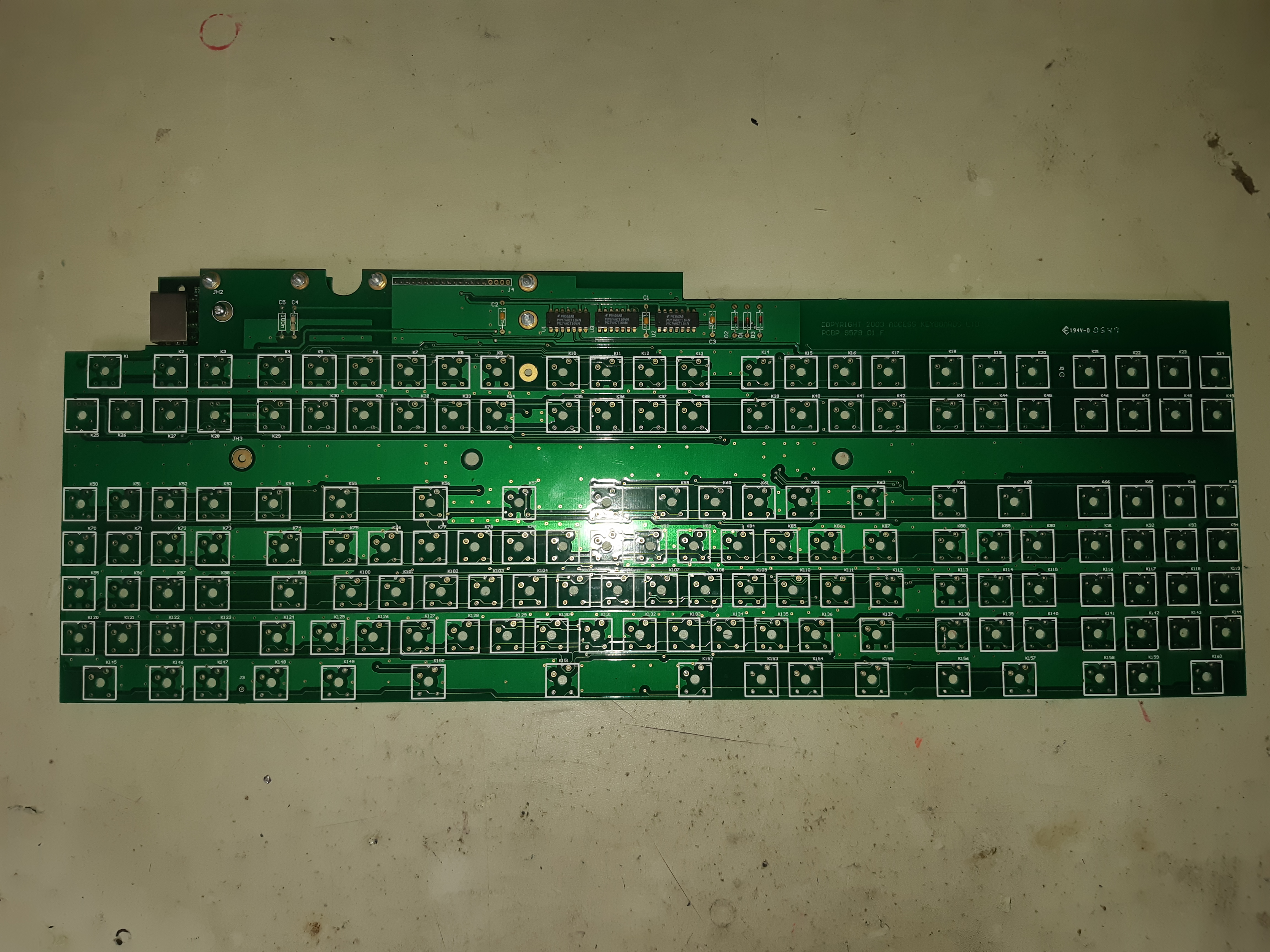

it's been out of production for almost 20 years. i called the manufacturer and they have no record of it even though their company name is on the silkscreen
nova pike
Not all of the QMK matrix functions are available in circuitpython, unfortunately. I know QMK supports shift register matrices, but CircuitPython doesn't, and I'm not quite sure if they have a roadmap for supporting that in the near future.
royal gulch
you will have to write the matrix-scanning code yourself, as keypad doesn't have support for a key matrix with shift registers
nova pike
Although I think QMK for RP2040 IS on their roadmap, I don't know how far out it is, as it relies on some other feature in another framework to support the RP2040.
royal gulch
there are branches for qmk that already work on rp2040
nova pike
Oh, so it does. Well, at least that's an option. KMK isn't there yet, unfortunately.
echo adder
royal gulch
there are branches for qmk that already work on rp2040
oh awesome!
didn't know that
royal gulch
afaik it's not yet merged to the main branch
echo adder
do you have a link to the branch you found?
nova pike
royal gulch
afaik it's not yet merged to the main branch
Nope, still a few outstanding items, it seems. https://github.com/qmk/qmk_firmware/pull/14877
royal gulch
nova pike
Nope, still a few outstanding items, it seems. https://github.com/qmk/qmk_firmwa...
I know people who use it
possibly third-party forks, though
nova pike
https://github.com/KarlK90/qmk_firmware/tree/feature/raspberry-pi-rp2040-support is probably incomplete, but it might work if you want to try it out.
honest bane
echo adder
apologies if this is spammy of me (feel free to delete)
So I finally understand...
(If you put URLs inside angle brackets: < >, then embeds are suppressed. You don't need to use the "hiding" syntax)
also you can always delete an embed. Hover over it and click the "x" that appears at its upper right
echo adder
honest bane
(If you put URLs inside angle brackets: `< >`, then embeds are suppressed. You d...
TIL. thank you!
 nimble burrow
Hello guys!
I want to make my usb mechanical keyboard wireless using two rp2040s and nRF24L01 modules to make a sender (which will be inside my keyboard) and a receiver (connected to my computers usb port). But the issue i have at the moment is that i haven't been able to find any easily understandable documentation on getting a keyboard input from a usb connector. I have found some projects that either use a usb OTG adapter to get the signal or a PIO. which can be found here : https://github.com/sekigon-gonnoc/Pico-PIO-USB
https://github.com/raspberrypi/pico-examples/tree/master/usb/host/host_cdc_msc_hid
But what i would want to do is somehow get this working with circuitpython (since i'm a beginner and that would make coding the nRF24L01 modules easier)
So my question is if theres any projects that are similar to this that could help me understand things better. Or is there some type of circuitpython library that already adds usbhost keyboard support?

GitHub
USB host/device implementation using PIO of raspberry pi pico (RP2040). - GitHub - sekigon-gonnoc/Pico-PIO-USB: USB host/device implementation using PIO of raspberry pi pico (RP2040).
GitHub
Contribute to raspberrypi/pico-examples development by creating an account on GitHub.
royal gulch
circuitpython doesn't support usb host yet, there is some early work on it, but it's not yet usable
nimble burrow
royal gulch
circuitpython doesn't support usb host yet, there is some early work on it, but ...
and is there any possible way i could make a program running in c that gets the key presses and then it send it to circuitpython?
royal gulch
nimble burrow
and is there any possible way i could make a program running in c that gets the ...
sure, that repository you linked has code like that
finite rose
@nimble burrow I'd recommend using nRF52840 instead because they have built in BLE
nimble burrow
finite rose
<@434323855973023744> I'd recommend using nRF52840 instead because they have bui...
i want to avoid general bluetooth connectivity since that seems to have way more lattency for some reason
finite rose
BLE goes down to 7 or 11ms intervals IIRC
which is probably fine
the fewer chips you have, the simpler the coding will be
full speed USB only checks every 1ms at its fastest
nimble burrow
i'll consider that. Thanks for the info!
 red nova
Hello! Is this the right place to ask a question about adafruit_hid?
 tired juniper
It's not a bad place, but you might get more support quickly in #help-with-projects, #help-with-circuitpython, or #help-with-arduino
red nova
Thank you! I’m just trying to figure out how to hold down a key until release.
(I want to make another shift key on the macropad)
 neat fossil
I pondered that for a minecraft crouch-lock function earlier, I think it is possible, despite my desires my macropad is chilling in storage :-)
gusty ocean
Sorry for pinging, but, is there someone at @earnest dew that can give me approval or endorsement to use the Adafruit Macropad VID/PID (0x239A/0x8108) for the QMK port for it? Support for rp2040 is soon to arrive to QMK and I already have a stable port it
 earnest dew
@gusty ocean hi hi, all depends! please email pt@adafruit.com with an overview of what you're requesting/doing with it, etc. etc.
we'll take a look and get back to ya!
appreciate ya checking and contacting us
gusty ocean
Amazing! tysm, i will redact the email asap
gusty ocean
Just a heads up!
QMK just added support for RP2040 in the develop branch.
Here my pr to add support for the Macropad:
https://github.com/qmk/qmk_firmware/pull/17512
GitHub
Description
Add support for the Adafruit Macropad RP2040.
This PR includes a driver for the SPI OLED that uses a modified version of the core driver with the difference of the transport protocol, u...
 wooden lake
this is awesome news, got it up and running pretty swiftly and works as expected
can't seem to get via to find it yet, but otherwise works fine
gusty ocean
wooden lake
can't seem to get via to find it yet, but otherwise works fine
Oops sorry hadn’t read the channel
You’ll need to compile a keymap with VIA enabled and sideload the board definition
Sideload this and VIA will recognize the macropad 😄
wooden lake
thanks for the response! that works perfectly - currently testing with a handful of layers and macros. excellent work!
gusty ocean
Another update, the Macropad is now merged into develop 😄
 warm lodge
Does anyone know if there is a pcb profile for kicad, for the large kailh switches? (product 5307)
nova pike
It should be the standard footprint x4?
warm lodge
I think they are a bit different, for example the legs are flat to fit on a quick connect cable, like the N&P project.