#help-with-arduino
1 messages · Page 16 of 1
 fair jasper
i don't recall. uploading is no longer working:
Traceback (most recent call last):
File "C:\Users\tract\AppData\Local\Arduino15\packages\megaTinyCore\hardware\megaavr\2.6.10/tools/prog.py", line 286, in <module>
 leaden walrus
go back to blink example and try to get that working again
fair jasper
i pulled out the stemma wire and hard-connected USB power to the Vin & G pins. clock @ 20.
going back to the blink...
Something about fuses on the blink upload. Error is:
pymcuprog.serialupdi.application - WARNING - Cannot read SIB, hard reset...
pymcuprog.serialupdi.physical - INFO - Sending double break
pymcuprog.serialupdi.physical - INFO - Double-break sent. Retrying.
pymcuprog.serialupdi.physical - INFO - Opening port 'COM14' at '57600' baud
pymcuprog.serialupdi.application - ERROR - Hard reset failed.
Traceback (most recent call last):
  File "C:\Users\tract\AppData\Local\Arduino15\packages\megaTinyCore\hardware\megaavr\2.6.10/tools/prog.py", line 286, in <module>
    main()
  File "C:\Users\tract\AppData\Local\Arduino15\packages\megaTinyCore\hardware\megaavr\2.6.10/tools/prog.py", line 128, in main
return_code = pymcuprog_basic(args, fuses_dict)```what are you using for a UPDI programmer?
fair jasper
adafruit FTDI Friend
leaden walrus
attached with a resistor like this?
https://learn.adafruit.com/adafruit-attiny817-seesaw/advanced-reprogramming-with-updi#step-3138713
fair jasper
yes, the top picture
leaden walrus
not sure then. maybe check all the connections, etc.
seems like something basic is not working in terms of UPDI progamming
it might also be driver related, for the FTDI, but would expect that to have been an issue much earlier
fair jasper
ok, I'll wiggle the wires (which usually works, unfortunately) and look for the short. let's try again tomorrow, perhaps... it's dinner time here on the east coast.
thank you SO MUCH for your time. It's really helpful.
leaden walrus
ok. good luck. keep just trying the blink example upload.
change blink rate, upload again, etc.
to work out all the possible kinks with UPDI programming
fair jasper
will do
 heady escarp
Hi, I have a question about some weird movement of some servos I have connected in my metro Express M0, this happen every time I power cycle the board. Not sure if it's the right forum?
 pale wadi
Hi! I hope this is the correct forum.
I have an ENS160 sensor connected to a raspberry pi (double checked the wiring) and this script
import smbus
import time

ENS160_I2C_ADDRESS = 0x53  # Adjust if needed

bus = smbus.SMBus(1)
def read_ens160_co2(bus):

    CO2_DATA_REG = 0x24  # from data sheet
    co2_bytes = bus.read_i2c_block_data(ENS160_I2C_ADDRESS, CO2_DATA_REG, 2)
    co2 = (co2_bytes[0] << 8) | co2_bytes[1]
    return co2
To read the sensor data, but read_ens160_co2 always returns 0. Am I missing something obvious ? (i2c detect also shows the device and on the same chip i can also read the temperature AHT21, but the co2 value is just always empty) Would be very thankful for any advise here 🙏
fair jasper
leaden walrus
change blink rate, upload again, etc.
I figured out my UDPI issues and deduced that one ATtiny is fried (or there's a short on the soldered parts). It does not I2C scan when the other ATtiny does.
So how do I change the default firmware to work for a servo?
 eternal cloud
pale wadi
Hi! I hope this is the correct forum.
I have an ENS160 sensor connected to a r...
eternal cloud
pale wadi
Hi! I hope this is the correct forum.
I have an ENS160 sensor connected to a r...
This is the Arduino channel, and you're using CPython on a Raspberry Pi... so not the correct forum 😉
Try https://discord.com/channels/327254708534116352/538149593246859313
Adafruit does have a CircuitPython library for a ENS160 board, that you can use directly (if you install the blinka compatibility layer on your rasp pi), or take inspiration from:
https://learn.adafruit.com/adafruit-ens160-mox-gas-sensor/circuitpython-python
https://docs.circuitpython.org/projects/ens160/en/latest/
eternal cloud
heady escarp
Hi, I have a question about some weird movement of some servos I have connected ...
Are you using Arduino code on your Metro Express? Then right forum.
If not, https://discord.com/channels/327254708534116352/537365702651150357 or https://discord.com/channels/327254708534116352/330406777009209346 would be more appropriate.
In any case, posting your code (and maybe pics of your wiring) would be helpful.
leaden walrus
fair jasper
I figured out my UDPI issues and deduced that one ATtiny is fried (or there's a ...
if you've been able to replace the attiny and have UPDI uploading working again, start with the default firmware (PID 5690 example sketch) and make sure you can talk to the attiny via the seesaw library and generate some PWM output. the default firmware will produce PWM output, just not exactly what is needed for servos
 crisp hinge
Hello, according to this discussion, could one of you please confirm that the schema is correct ?

For Vcc +, I connect the +12V from the power supply. For 0V, I connect the -12V from the power supply. What do I connect to the two Vin points on the left side of the diagram?
Thanks a lot for your help !
 stable forge
crisp hinge
Hello, according to this discussion, could one of you please confirm that the sc...
stable forge
crisp hinge
Hello, according to this discussion, could one of you please confirm that the sc...
madbodger only linked to that schematic to show you how to place the diode. It sounds like you already have something wired. Did you attach the relay coil directly to the microcontroller pin?
don't connect -12v as ground
we'd have to see the whole circuit
did we already point you to https://www.adafruit.com/product/5648 ?
Sparky the Blue Smoke Monster shows up whenever the magic smoke is let out of an electronic component. And his very favorite is whenever folks first start with electronics and robotics: ...
crisp hinge
stable forge
madbodger only linked to that schematic to show you how to place the diode. It s...
Ok mb my question was under the schema, madbodger linked me to linked me schema right
crisp hinge
stable forge
we'd have to see the whole circuit
Only have this

On 0v , what do I have to connect ?
The ground of the power supply ?
crisp hinge
stable forge
don't connect -12v as ground
^
stable forge
a 5v regulator does not put out +5v and -5v: it puts out 5v and ground. +5v and -5v would be a 10v difference between the terminals, and I don't think that's what you have here
if you measured it with a multimeter you would see 5v. Similarly the 12v you have coming in is probably not +12 and -12, it's probably 12v as measured across the terminals.
there are power supplies that supply both negative and positive voltages with respect to a ground reference, but I don't think that's what you have here
crisp hinge
Yes it’s 5v and ground mb
Same for 12v
So according to this schema do you have any suggestions of what could be done to avoid the lcd screen problem ? Or any idea on where to place the zener diode ?
stable forge
in the schematic you have the relay connected directly to a pin on the TTGO. Could you link to a shopping link or whatever for the relay? And what pin is the relay connected to on the TTGO?
The TTGO may not be able to drive the relay directly, depending on its current requirements
crisp hinge
This one ?
stable forge
it looks like there are two, one above the the other?
crisp hinge
(No the other one)
stable forge
yes, please specify what that part is
that's why I suggested the https://www.adafruit.com/product/5648. It would substitute for the relay altogether, and it includes the diode as well
crisp hinge
stable forge
The TTGO may not be able to drive the relay directly, depending on its current r...
I’ll send you a link to the relais that I use, but the whole « schema » is working if we change the electric strike by a simple colored led
I already bought the diode so I just need to know where to place it
 crisp hinge

5PCS Module de Relais 5V, 1 Canal Relais Module Bouclier ave D'optocoupleur, Haut Niveau Carte D'extension Relais, Bas Niveau Module Relais Déclenchement, Module Commutation Relais Pour Arduino (5V)
Here is the relay
Basic one
crisp hinge
stable forge
what kind of diode is that again?
The diode is 1N4734
stable forge
ok, that is a 5.6v, so that is not going to work as a snubber on the striker (the lock, I think you mena)
because you are using 12v there. It could be used on the other side to snub the relay coil, but I don't think you need it there
crisp hinge
So I have to change the relay ?
crisp hinge
stable forge
ok, that is a 5.6v, so that is not going to work as a snubber on the striker (th...
It won't work even with the Zener diode?
stable forge
the 12v will fry the zener, because the zener will go into breakdown at 5.6V and you are applying 12v for extended periods of time.
no, you need a higher voltage diode
crisp hinge
stable forge
no, you need a higher voltage diode
Do you have any link ? Or reference ?
stable forge
or just use a regular power diode, like a 1N4001
1n4148 might work too. What are the current requirements of the door solenoid?
crisp hinge
What is « solenoid » please ?
stable forge
it's hard to tell from the relay board (I found it listed other places) about whether it already has circuitry to protect against
Bobine allongée constituée par un fil conducteur enroulé qui crée sur son axe un champ magnétique quand il est parcouru par un courant.
there is a solenoid in the electric lock
do you have a supply of electronic parts or are you ordering everyting one at a time?
crisp hinge
I have a supply of electronic parts but not for the diode
stable forge
but do you have any diodes at all?
crisp hinge
stable forge
there is a solenoid in the electric lock
The door is locked when it’s powered
stable forge
is there a spring on the lock, so that it has to stay energized to stay in one position or the other?
crisp hinge
stable forge
but do you have any diodes at all?
I’ll ask to my colleagues
stable forge
any old power diode like !N4001 or a signal diode like 1N4148 (which has several hundred mA forward current capability) should work
these are very common
crisp hinge
stable forge
any old power diode like !N4001 or a signal diode like 1N4148 (which has several...
Ok lets go try this, I’ll let you know
Thanks for you time and your explanation that’s really interesting !
 tame pollen
Anyone know of a good I2C library that is compatible with Arduino Nano ESP32?
eternal cloud
tame pollen
Anyone know of a good I2C library that is compatible with Arduino Nano ESP32?
A library for what?
If you mean I2C implementation for the board, that's part of the Arduino core, you just need to install the correct board package: https://docs.arduino.cc/tutorials/nano-esp32/getting-started-nano-esp32/
tame pollen
eternal cloud
A library for what?
If you mean I2C implementation for the board, that's part ...
Ooh okay thank you!
 lofty nimbus
I’m trying to add an i2c display to the mintysynth project, but there doesn’t seem to be enough memory, any ideas?
I tried to use gyveroled, but still not enough memory
 inland gorge
lofty nimbus
I tried to use gyveroled, but still not enough memory
inland gorge
lofty nimbus
I tried to use gyveroled, but still not enough memory
There's not much RAM left on the ATmega328 running MintySynth. You could try one of I2C character displays like this https://amzn.to/3VG4kYW but it may be just enabling the Wire library (I2C) with its buffers will be too much
lofty nimbus
Is it weird to use a second nano to run the display and related code?
 lethal yarrow
No, but you still have to communicate with it, so it provably won't help in this situation.
lofty nimbus
Outside of tapping into the existing pots, I would need to figure out getting the second nano to get the correct bpm. I feel like it wouldn’t be too hard, but I’m a noob, so I could be extremely wrong.
lethal yarrow
The difficult part there would likely be synchronization. Human hearing is surprisingly sensitive to phase shifts.
lofty nimbus
The BPMs wouldn’t be changing often, it’s more to be able to stay consistent. So if there is a delay or poor synchronization I think it would be still useful.
lofty nimbus
What if I determine the bpm from the pot value and not have any connection between the two arduinos. 🤔
 delicate cairn
https://learn.adafruit.com/adafruit-ano-rotary-navigation-encoder-to-i2c-stemma-qt-adapter
Has anyone used this before? Im detecting random button pushing in my program and im not sure how to eliminate it, ive had to comment out all the button controls i had in there to get it to work but i would really like to have the functionality figured out so i can used all the buttons

Adafruit Learning System
Navigate your next project over I2C
eternal cloud
delicate cairn
https://learn.adafruit.com/adafruit-ano-rotary-navigation-encoder-to-i2c-stemma-...
What do you mean by random, are you pressing the button or not?
Are you using the Arduino test code from the guide? If not, posting your code would be helpful
delicate cairn
eternal cloud
What do you mean by random, are you pressing the button or not?
Are you using t...
i am not pushing the buttons but i have an OLED thts telling me that the button has been pushed
delicate cairn
eternal cloud
it might have something to do with how you changed the example code
oh crap whatdidido
eternal cloud
you took if (!ss.digitalRead(SS_SWITCH_RIGHT)) {
and made it if (!ss.digitalRead(SS_SWITCH_RIGHT) == LOW) {
delicate cairn
im very new at this and chat gdp has been "helping"
delicate cairn
eternal cloud
you took ` if (!ss.digitalRead(SS_SWITCH_RIGHT)) {`
and made it` if (!ss.d...
i saw that erlier, i removed the ==LOW but it didnt seem to help
eternal cloud
delicate cairn
i saw that erlier, i removed the ==LOW but it didnt seem to help
it didn't? 🤔changed for all the buttons?
delicate cairn
eternal cloud
it didn't? 🤔changed for all the buttons?
yeash it was doing the same thing, do i need to add a condition to check?
eternal cloud
the buttons are pulled high, so they are active on low ... so basically checking for !( not ) digital read detects a press
how you wrote it is double negate, so it would detect button presses when nothing is pressed
delicate cairn
ok so i got rid of the ==LOW on all of them, do i need to add anything else to check if they have been pressed and like refresh? when it starts up the "buttons" is blank but if i push one it stays on the screen, not sure if thats bc it thinks its still being pressed or if its just stuck on the display, and it doesnt seem to respond to follow up
oh jk its just randomly displayed bottom and i never touched it
eternal cloud
delicate cairn
oh jk its just randomly displayed bottom and i never touched it
if i push one it stays on the screen
I think that's correct behavior, I don't see updates to the screen to delete
So, you changed the code, removed all ==LOW and it still displays ghost presses ?
delicate cairn
eternal cloud
> if i push one it stays on the screen
I think that's correct behavior, I don't...
seems that way, but its random, i may have an issue with my hardware or setup i guess, ive got it all jammed in a breadboard rn
delicate cairn
eternal cloud
> if i push one it stays on the screen
I think that's correct behavior, I don't...
ok not entirely random, happens when i move the scroll wheel
 pine bramble
anybody got an idea why when i try to upload the factory demo to my esp 32-s2 reverse tft feather i get errors with thing not being declared?
 dusk orchid
pine bramble
anybody got an idea why when i try to upload the factory demo to my esp 32-s2 re...
dusk orchid
pine bramble
anybody got an idea why when i try to upload the factory demo to my esp 32-s2 re...
Make sure you've selected the correct board in the arduino IDE, and followed the arduino setup steps (install the esp32 board manager url and board support package)
dusk orchid
which error did you fix, and now whats the new error message (as it wont compile there should be one)
You may benefit from closing and reopening the arduino ide as it caches somethings until restarted
eternal cloud
delicate cairn
hmm, that does look strange, but a bit difficult to figure out the issue... could you try running the simple sketch from the rotary guide? https://learn.adafruit.com/adafruit-ano-rotary-navigation-encoder-to-i2c-stemma-qt-adapter
it will give a clearer picture of what's going on, seeing all the button presses in the serial console
pine bramble
dusk orchid
which error did you fix, and now whats the new error message (as it wont compile...
i fixed all errors and uploaded the code but theres nothing showing up the backlite is working but closes for a split second after every 2 seconds
what do i do?
is the screen broken?
let me try to fix the code
either the screen is not working properly
or theres something wrong with the usb connection
i mean everything works on the board
except the screen
dusk orchid
pine bramble
i fixed all errors and uploaded the code but theres nothing showing up the backl...
It sounds like it might be rebooting, what do you see on the serial monitor when it runs?
pine bramble
nothing
 silent spruce
I am in a bit of a pickle here and would greatly appreciate any help or insights: I have 15 ESP32C3's that are continuously reading data from a BNO055 and storing that in an array. I want to send the newest sensor readout of all 15 ESPs to a central microcontroller before I pass it on through serial to my PC, I wanted to do that with an SPI bus first, but I have read that the maximum amount of devices is 9 for another ESP32 serving as a main controller. What alternatives are there? Or how would you approach this? Thanks in advance guys. If anyone needs keyboard or switches recommendation in return, let me know!
delicate cairn
eternal cloud
hmm, that does look strange, but a bit difficult to figure out the issue... coul...
tried that, it all works normally, i also checked the serial monitor with my code and its acting as if they are all held down
stable forge
silent spruce
I am in a bit of a pickle here and would greatly appreciate any help or insights...
Instead of using connections, you could just send data via advertising. You might lose some readings but that may not matter in your application.
example of such a project: https://learn.adafruit.com/bluetooth-le-broadcastnet-sensor-node-raspberry-pi-wifi-bridge
(just pointing it out for concept, I don't think you need the details)
 true nimbus
for 3v3 feather boards (i have a RP2040 specifically), do the analog inputs have 0—3.3V range, or 0—5V ?
is it possible to measure 0—5V (without adding a resistor) is what i'm asking
 deep lark
delicate cairn
deep lark
delicate cairn
is that flux on the board?
not judging, but if it's flux i'd recommend cleaning it up
dusk orchid
pine bramble
nothing
Make sure you turn on the serial USB option in Arduino upload settings (USB cdc enable), and rebuild and upload the example again, then you should see something on the serial monitor.
silent spruce
stable forge
example of such a project: <https://learn.adafruit.com/bluetooth-le-broadcastnet...
Cheers, I'll check it out. Though I was aiming for 30 Hz as I want to animate something in Blender through the sensors
 fair tusk
I want to connect a Adafruit ST7789 320x240 TFT Breakout to a Adafruit Feather RP2040 which SPI pins do i use?
 quartz furnace
I have an ESP NOW project I am working on that has “esp_now_register_recv(OnDataRecv); handler that executes any time there is something available
Question is there a way to temporarily halt new runs until other parts of the code are finished?
I have a U-blox Cellular module from SparkFUN I’m sending out SMS messagess from a ESP NOW event
Problem is the u blox device needs a bit more time if A few events come all at once
Need to prevent it from crashing
appears you can register and unregister callbacks … tinkering around modifying code
 pulsar sand
Hi there, I'm new to the server, I was wondering if anyone can help me, I've been playing with makecode with a cpx for a project, however a classmate of mine made something cool with arduino. My issue is I've installed the library for adafruit circuit playground, but now that I want to do something with makecode, the CPLAYBOOT won't appear as a drive on my finder window (yes I have a mac), because it's directly connected to arduino, does anyone know how i can include the cplayboot back?
 rough torrent
pulsar sand
Hi there, I'm new to the server, I was wondering if anyone can help me, I've bee...
rough torrent
pulsar sand
Hi there, I'm new to the server, I was wondering if anyone can help me, I've bee...
Double click reset?
Also for MakeCode related queries, you can use #help-with-makecode or the MakeCode Forums 😃
eternal cloud
pulsar sand
Hi there, I'm new to the server, I was wondering if anyone can help me, I've bee...
get CPLAYBOOT to appear on your board. If you're running MakeCode, click the reset button once. If you're running CircuitPython or an Arduino program, double-click the reset button. All the NeoPixels should turn green.
Just in case you don't know about this guide https://learn.adafruit.com/adafruit-circuit-playground-express , it should give you most of the info about how to use CPX
 balmy jay
Howdy, I have a project where I need high frame rate (60fps ideally), black and white video processing on an esp32 (critical that it is esp because the system relies on espnow). The esp cam isn’t cutting it because I am stuck at a max of about 15fps because of jpeg decompression. Ideally each board is under $25 because it’s gonna be a multi camera system. Are there any boards that exist that have these capabilities? I don’t need a ton of resolution (320x240 is plenty) and my processing is just doing some threshold info and basic blob detection. If you have any way to get the performance up (I know the max of esp cam is 50fps which would be fine), please let me know.
I looked at the m5stack from adafruit but it seems identical to a normal espcam
There is some proof here that we can get higher frame rates so I will try the eloquent library tomorrow and see if I can get some better results (currently using the default espcam lib) https://github.com/bharathsudharsan/TinyML-CAM

GitHub
Code for MobiCom paper 'TinyML-CAM: 80 FPS Image Recognition in 1 Kb RAM' - bharathsudharsan/TinyML-CAM
I have an ai thinker clone from microcenter as my espcam, I’m not sure if it’s just cheap hardware holding me back or what
balmy jay
balmy jay
There is some proof here that we can get higher frame rates so I will try the el...
Looks like I read this wrong, it’s 80fps for only the extraction and classification, you are still limited by camera throughput
balmy jay
Ok so I found this module, HM01B0, which seems to be meant for raspberry pi pico but I think it could work with a esp32 so I might pick one up and see
If anyone knows about framerate let me know
balmy jay
Main thing is I can’t have any JPEG processing because it is too costly and it needs to be a direct buffer I can threshold and then blob detect
crisp hinge
Hello, to secure my LoRa connection, I reboot everyday all of my system at the same hour.
Actually I'm using theses types of clock (picture)
It seems like it's not precise enough; it can vary sometimes. Do you have any suggestions or whatever? Does Adafruit sell something that can be useful? Thanks.

 tardy iron
 dapper acorn
how do i solve the EEPROM.h issue
dapper acorn
how do i solve the EEPROM.h issue
pico is RP2040, which is recall lacks EEPROM. you can maybe find a library that emulates EEPROM in flash
dapper acorn
tardy iron
pico is RP2040, which is recall lacks EEPROM. you can maybe find a library that ...
something like this??

iam a complete noob..
stable forge
crisp hinge
Hello, to secure my LoRa connection, I reboot everyday all of my system at the s...
RTC chips often have a timer interrupt capability. They typically bring a pin low when the alarm goes off. The low can be pulsed (down and then back up) so it can be used as a RESET toggle. See the datasheets for the chips on our RTC breakouts. https://www.adafruit.com/search?q=rtc
tardy iron
dapper acorn
something like this??
that’s for a different chip. it looks like the Philhower core has EEPROM emulation. what are the exact error messages you’re getting? (turn on verbose compile in settings)
dapper acorn
tardy iron
that’s for a different chip. it looks like the Philhower core has EEPROM emulati...
wait where are the settings😅
tardy iron
dapper acorn
wait where are the settings😅
i don’t know. you seem to be using a newer version of the Arduino IDE that i’m not familiar with, and i don’t know what OS you’re on
dapper acorn
tardy iron
i don’t know. you seem to be using a newer version of the Arduino IDE that i’m n...
iam on windows
the error i see is
 tardy iron
dapper acorn
the error i see is
tardy iron
dapper acorn
the error i see is
what board do you have selected?
dapper acorn
 tardy iron
dapper acorn
tardy iron
dapper acorn
maybe it’s a different one? can you open the board manager and look at your installed board packages for Raspberry Pi Pico or RP2040?
dapper acorn

i think the pi pico is the best option..
even if i choose the nano it still says that the EEPROM libary or something like that is not installed
tardy iron
dapper acorn
even if i choose the nano it still says that the EEPROM libary or something like...
yeah it’s looking like it’s not finding the EEPROM library correctly. try with the Arduino 1.8.x IDE? the new IDE has supposedly had some weird problems
dapper acorn
tardy iron
yeah it’s looking like it’s not finding the EEPROM library correctly. try with t...
i can try to install that
dapper acorn
tardy iron
yeah it’s looking like it’s not finding the EEPROM library correctly. try with t...
 tardy iron
dapper acorn
tardy iron
dapper acorn
that's… not related to the EEPROM library
dapper acorn
ow..
tardy iron
dapper acorn
is there some guide somewhere that you're following? what are the complete error messages related to that screenshot?
dapper acorn
tardy iron
is there some guide somewhere that you're following? what are the complete error...
yeah a sand clock from electar ors
the complete error message is super long and includes my full name etc 100 times
i van try to edit those things out and send it
C:\Users\AppData\Local\Temp\arduino_modified_sketch_28648\sketch_apr03a.ino: In function 'void setup()':
sketch_apr03a:683:26: error: 'INPUT_PULLDOWN' was not declared in this scope
pinMode(PIN_PIR_SENSOR,INPUT_PULLDOWN);
^~~~~~~~~~~~~~
C:\Users\AppData\Local\Temp\arduino_modified_sketch_28648\sketch_apr03a.ino:683:26: note: suggested alternative: 'INPUT_PULLUP'
pinMode(PIN_PIR_SENSOR,INPUT_PULLDOWN);
^~~~~~~~~~~~~~
INPUT_PULLUP
C:\Users\AppData\Local\Temp\arduino_modified_sketch_28648\sketch_apr03a.ino: In function 'boolean process_rcv()':
sketch_apr03a:2871:24: error: 'class HardwareSerial' has no member named 'printf'; did you mean 'print'?
Serial.printf("%u Bytes in struct settings exceed 56 bytes in RTC\n\r",sizeof(settings));
^~~~~~
print
dapper acorn
tardy iron
is there some guide somewhere that you're following? what are the complete error...
not as long as i thought but ^^
tardy iron
dapper acorn
not as long as i thought but ^^
you shouldn't be getting that INPUT_PULLDOWN missing error if you have the correct board selected
dapper acorn
tardy iron
you shouldn't be getting that `INPUT_PULLDOWN` missing error if you have the cor...
how do i choose the board in this version?
tardy iron
dapper acorn
how do i choose the board in this version?
there should be a "tools" menu that has a "board" item
tardy iron
dapper acorn
how do i choose the board in this version?
https://learn.adafruit.com/rp2040-arduino-with-the-earlephilhower-core/installing-the-earlephilhower-core if it's not already installed

Adafruit Learning System
Use Earle Philhower's core to put Arduino on all your favorite RP2040 devices
dapper acorn
its a different language for me lemme find something
dapper acorn
tardy iron
https://learn.adafruit.com/rp2040-arduino-with-the-earlephilhower-core/installin...
how do i know which serial port my rpi is in?
it does not say a serial port how do i connect it to arduino IDE?
 tardy iron
dapper acorn
it does not say a serial port how do i connect it to arduino IDE?
tardy iron
dapper acorn
it does not say a serial port how do i connect it to arduino IDE?
i think it’s in bootloader mode. do you see a USB disk drive called something like PICOBOOT?
i think Arduino can load code that way without a serial port
dapper acorn
no
but i just selected every single possible thing that was in serial monitor bc i knkow all my other things have some sort of protection
sooooooo
basicly it was com6
but device manager did not say it was com6
deep lark
if this is your first time using arduino on rp2040, you need to manually trigger bootsel as it does not reboot to download mode automatically
tardy iron
dapper acorn
but i just selected every single possible thing that was in serial monitor bc i ...
the port menu in Arduino should have been able to tell you which one was the Pico, i think
dapper acorn
tardy iron
the port menu in Arduino should have been able to tell you which one was the Pic...
prob yess
but did i know it
nope/:
dapper acorn
deep lark
if this is your first time using arduino on rp2040, you need to manually trigger...
iam only gonna program it 1 time
deep lark
doesn't matter, if the original firmware is not arduino then uploading the code through arduino ide does not work
try holding down bootsel and replug the pico, you should see a new storage device on your computer
now you can try upload the code and see if it works
 nocturne burrow
Hello,
Following recommendations I saw online, I plan to power my Adafruit 32u4 feather and my Adafruit TB6612 motor driver from the from 4 AA NiMH rechargeable batteries in series for a total of 4.8V using two buck converters. The buck converter I chose was the Adafruit MiniBoost TPS61023. Before I hook up my circuit on the breadboard, I wanted to confirm that my circuit will not damage any of the components and work how I intended. Please take a look at my Fritzing diagram and let me know if everything looks good. I am using two TT Motors I believe. I got them in a robotics kit from Adafruit. According to the robot kit listing, the motors drive with 3-6VDC, use 200-400 mA to run, and have a 1.5A hard stall.


 timber void
Hi everyone, i have a question. I recently found an AT89C2051 microcontroller and i decided to try and use my arduino to program it. The actual programming and stuff I have no trouble with, however, it needs 12v applied to the RST pin whenever you want to enable the programming mode. Then it needs to go back down to H, which is 5v, to verify the byte you just wrote. repeat x1000. So I need to find a way to apply 12v, H (and L) freely, presumably with high frequency of switching. I have looked into several ways to do it and I have talked to my much more knowledgeable friends, but i decided to ask here just in case. How would you do it?
i will also say that i don't have a lot of experience in electronics specifically, especially making stuff physically and especially especially soldering, and I am fully aware of that and i'm trying to learn
 north stream
I'd probably have a pull-up transistor with a level shifter for each voltage level, and some logic to avoid turning them both on at once.
timber void
ty
 versed trail
possible to do transparent ps/2 emulation for laptop touchpad? as in, OS uses correct drivers despite device being USB -- notably for multitouch
 hollow olive
are there any somewhat big (5-6") displays with capacitive touch that are reasonably easy to use with arduino? i can only find up to 3.5"
stable forge
hollow olive
are there any somewhat big (5-6") displays with capacitive touch that are reason...
That is not so easy to find, because larger displays are expensive enough that they usually are for higher-end processors and don't have the display controllers that make using with weaker microcontrollers easy. You can usually find a cap touch overlay to fit over whatever display you are looking for. What is your use case?
hollow olive
i need to display a dashboard with information that should be displayed reasonably big so it's easy to see and i'd need it to be cap touch so it can be operated with gloves / the back of a pen / something else
stable forge
hollow olive
i need to display a dashboard with information that should be displayed reasonab...
and what kind of arduino? Is this a battery-powered ting?
hollow olive
it doesn't have to be mobile, so power consumption isn't a problem, i can keep it plugged in
as to what arduino: i haven't decided yet, mostly the arduino environment is something i'm familiar with so i was hoping for a display that can be used with a popular library or something
stable forge
you might consider a Raspberry Pi (not Pico) of some kind instead, there are plenty of displays for that
hollow olive
actually i just found a 4" display that might work. i'll draw some mockups to scale and see if it could be big enough
if not i will consider some raspberry pi
thanks for the help :)
 edgy ibex
Looking for some PlatformIO expertise here. I've switched wholesale from using the Arduino IDE to using PlatformIO. How much, if anything, of the old Arduino installations do I need to keep? Or can I uninstall / delete everything, and PlatformIO will take care of downloading its own copies of libraries that I might be using
pine bramble
greetings. Im building a MIDI controller with a Feather RP2040 and Arduino with Control_Surface library. I was having issues with the full-build so I downsized to a single pot and a single button. the pixel and pot work as expected, the button not at all. I have tested the continuity across the path and everything is connected and the button goes from 0 to 3v when pressed. here is the code, just pieced together from Control_Surface lib examples. not sure what Im doing wrong. any input or pointers are much appreciated.
 inland gorge
pine bramble
greetings. Im building a MIDI controller with a Feather RP2040 and Arduino with ...
inland gorge
pine bramble
greetings. Im building a MIDI controller with a Feather RP2040 and Arduino with ...
And your MIDI receiver is listening to MIDI channel 2?
pine bramble
inland gorge
And your MIDI receiver is listening to MIDI channel 2?
yes, my MIDI receiver is omni, (Pure Data) listening on all channels and shows which channels are receiving what messages, have also tried it in another omni software. I also tried changing the channel # to see if there was a different result and have tried listening on the specific channel# as well, as opposed to "listening" in omni.
inland gorge
pine bramble
yes, my MIDI receiver is omni, (Pure Data) listening on all channels and shows w...
I reread your description. It sounds like you have your button wired up as active-HIGH (goes HIGH when pressed). It’s more common to have the button wired up as active-LOW, and the Button docs assume this, even enabling the internal pull-up resistor for you so you don’t need an external one : https://tttapa.github.io/Control-Surface-doc/Doxygen/d2/daa/classCCButton.html#details
fair tusk
I accidentently fed 12V into an Arduino Mega pin for 2 seconds before unplugging and smelt burning. I have a Adafruit Sound FX board connected to the mega via Serial1 that stopped working. The FX board still boots and the Mega board still boots, but it wont play files. Did i burn the FX board too?
I also have a Adafruit PAM8302A amp on the output of the Right Audio pin that goes to a speaker
pine bramble
inland gorge
I reread your description. It sounds like you have your button wired up as activ...
excellent! thanks for that... yes, I do have it setup so the button "goes high" so I will definitely try "goes low"
 tender sinew

Turning physarum polycephalum (slime mold) into an oscillator with Arduino, Ableton Live and Max4Live. Has been used in my opera "LOG" written for "CoOPERAtion Art&Science" project.
I am trying to achieve this
wonder how it's connected
It is getting signal from that slime mold and use that number for osc
As long as I can get a certain number from arduino, I can take care of synthesizing part. But I wonder how exactly it's connected in that video.
inland gorge
tender sinew
As long as I can get a certain number from arduino, I can take care of synthesiz...
It may be doing something as simple as a just a bare wire on an analog pin. The ambient EMF from a finger touching the metal foil can cause the analog values to change outside of some baseline. So the code may be as simple as:
void setup() {
  Serial.begin(9600);           //  setup serial
}
void loop() {
  int val = analogRead(A0);  // read the input pin
  Serial.println(val);          // debug value
}
yo! thanks for your answer. But I see two wires and one alligator clips connected to that dish
green wire seems like it's connected to one of the Analog inputs
and black wire is to ground? then what is that white alligator clip?
inland gorge
tender sinew
and black wire is to ground? then what is that white alligator clip?
yep black is most likely to ground. The white jumper doesn't seem to connect to the arduino so it may be just being used to add more metal (more sensitivity) to the system
tender sinew
inland gorge
yep black is most likely to ground. The white jumper doesn't seem to connect to...
so maybe try hooking up one wire to one of the Analog pins, and another wire to the ground and see how it goes?
inland gorge
tender sinew
so maybe try hooking up one wire to one of the Analog pins, and another wire to ...
yep, that's what I would try
tender sinew
Thank you man! I will let you know how it went tmrw!
inland gorge
tender sinew
Thank you man! I will let you know how it went tmrw!
No prob. 🙂 If that doesn't work well enough for you, you should look into "capacitive sensors". There's a lot of code for doing this on Arduino. Here's one tutorial https://www.digikey.com/en/maker/tutorials/2021/how-to-add-capacitive-sensing-to-any-arduino-project

DigiKey
Capacitive proximity and touch sensors represent great for adding engaging and intuitive input options to DIY projects.
tender sinew
inland gorge
No prob. 🙂 If that doesn't work well enough for you, you should look into "capa...
thank you so much!!
 magic idol
Hey there
So im usng multiwii with a nano ang mpu6050 but the model on multiwii doesnt seem to update
Ive tested the 6050 and its working
 ionic shale
Hey, I was wondering if MPU6050 would do just fine for getting the orientation of itself, since it has accelerometer/gyroscope, without a magnetomete
 orchid fossil
Has anyone tried to utilize bit-banging on the ESP32 SDIO interface for SPI communication? I couldn't find any project online addressing this specific approach.
 pallid sage
Found a microcontroller simulation website, Wokwi. Doesn't look evil offhand.
dusk orchid
pallid sage
Found a microcontroller simulation website, Wokwi. Doesn't look evil offhand.
Not evil, been using for a long time, love it
 crude heart
anyone have experience with arduino and Midi CC control?
inland gorge
crude heart
anyone have experience with arduino and Midi CC control?
Yes
 twilit nexus
How do I add functionality to/override functions from libraries in arduino? For example, I am trying to make a snake game on an 8x8 LED matrix and I want to use the arduino Linked List library to represent the snake. I simply want to modify the .add(newNode(x, y)) function to call the drawLED(node.x,node.y) function from another library for controlling led matrices
stable forge
twilit nexus
How do I add functionality to/override functions from libraries in arduino? For ...
you can copy the library and modify it.
twilit nexus
stable forge
you can copy the library and modify it.
And then include my modified library at the top of the program?
rough torrent
Yes
stable forge
twilit nexus
And then include my modified library at the top of the program?
you could also write a wrapper routine that does the add and drawLED. That would not require changing the library. def add_and_draw(...
twilit nexus
alright thank you that was very helpful. Follow up question: If I modify, for example, the LinkedList library to call functions from another library, must I put an include statement at the top of the edited linkedList library for the other library?
 green lake
hi everyone, i have a problem with uploading sketches to my Arduino nano esp32
i use the newest version 2.3.2
these are the error messages:

i use the windows version, the data cable works fine, and there are no problems with other boards (the elego uno r3 works fine, but it doesn‘t fit for my project. Too little analog pins)
eternal cloud
green lake
i use the windows version, the data cable works fine, and there are no problems ...
Did you install the ESP32 board package and select the correct board?
Also:
Note: You may see two versions for the Nano ESP32 available to pick in the board selector, one USB(COM21 in picture) and DFU(3-2 in picture). If you do, select the one with USB.
https://docs.arduino.cc/tutorials/nano-esp32/getting-started-nano-esp32/
green lake
eternal cloud
Did you install the ESP32 board package and select the correct board?
Also:
> ...
yes, i selected the USB(COM21) and i had downloaded the ESP32 board package version 2.0.13
i have already tried troubleshooting on their official website, but i didn‘t find anything there
 hidden jasper
I currently have a project I'm working on where I am using the Seeed Studio Xiao ESP32-C3 https://wiki.seeedstudio.com/XIAO_ESP32C3_Getting_Started/
https://www.seeedstudio.com/Seeed-XIAO-ESP32C3-p-5431.html
I am using the Arduino IDE to program it. My project is basically a 'switchbot' (https://www.switch-bot.com/products/switchbot-bot)
i.e ESP32-C3 using BLE, Servo Motor, and a Capacitive touch sensor. Till now, all the components are working and have been assembled together. Right now, it is housed in a 3D printed enclosure and is powered by the USB C port on the Microcontroller attached to a 5V Phone charger. Im using the RemoteXY (https://remotexy.com/en/editor/) app for controlling the 'switchbot'.
I plan to make this device battery operated. The present setup draws a bit of current. Only enough for it to run about 28 hours on a 2000mA battery.
I looked around a bit and found out that the ESP32-C3 has a couple of sleep modes which unfortunately disables the WiFi and BLE. I also found out that in the Modem Sleep Mode, I can configure the wireless connections to be active. I thought of setting a WiFi or BLE wakeup trigger and keep the ESP in modem sleep mode the rest of the time.
I cant seem to find any way or method to do this in the Arduino IDE. If anyone can help me do this that would be great.
If not possible can you suggest some other low power micro controller whether using WiFi or BLE(Preferrable) to get this project done.
Thankyou in advance😊😊
Help
inland gorge
hidden jasper
I currently have a project I'm working on where I am using the Seeed Studio Xiao...
Presumably you're using the arduino-esp32 Arduino core from Espressif. On their documenation site for the core, there's a section on their APIs for Deep Sleep: https://docs.espressif.com/projects/arduino-esp32/en/latest/api/deepsleep.html
There are also several tutorials on the net, good keywords are "esp32 arduino sleep". Here's a couple:
- https://randomnerdtutorials.com/esp32-deep-sleep-arduino-ide-wake-up-sources/
- https://www.instructables.com/ESP32-Deep-Sleep-Tutorial/
While these are all for the original ESP32, I believe they should work for ESP32-C3, as Espressif's docs for arduino-esp32 don't see to call it out.
hidden jasper
I need BLE function to be on at all times
All the sleep modes on the ESP-32 turn off RF capabilities by default
These are from the ESP32-C3 documentation on expressif


This says that I can opt to keep WiFi or BLE on during Modem Sleep mode
I dont know how to do this
Googled the h*ll out of it on how to keep BLE on during Modem Sleep, couldnt find anything useful
Im not that advanced on the ESP32s'
So it would be helpful if I got some directed towards some Arduino code to do this
inland gorge
hidden jasper
So it would be helpful if I got some directed towards some Arduino code to do th...
This article seems to cover it a bit: https://mischianti.org/esp32-power-saving-modem-and-light-sleep-2/ but I don't see any real Arduino APIs for doing this, so you may need to drop down into ESP-IDF to do it. I think this is the page that gives some examples on that: https://docs.espressif.com/projects/esp-idf/en/stable/esp32/api-reference/system/sleep_modes.html#application-example
 ornate storm
what's the right syntax to send values to a characteristic using the Bluefruit library? e.g. send "1234567" to some characteristic?
I can't seem to get it to work. I've tried .write with a hex byte representation of the data, I've tried sending single digits at a time, I've tried reversing the order just in case, etc
 ripe coral
Hello, i'm using an Arduino MKR Wifi 1010 with an Adafruit PMSA003I Air Quality Breakout.
I'm uploading a sketch with that uses the Wifi card. The problem is:
- When uploaded from computer, sketch works
- When disconnected from power and restarted, CHRG light is on and flickering fast, WiFi.begin() stops working.
- When the PMSA003I sensor is disconnected from the Arduino, and Arduino is restarted, CHRG light does not appear anymore.
Does anyone know what the problem is?
Edit:
The problem is fixed, I did:
- Disconnect sensor when starting up
- After WiFi has been connected, reconnect sensor
eternal cloud
ripe coral
Hello, i'm using an Arduino MKR Wifi 1010 with an Adafruit PMSA003I Air Quality ...
ideally you wouldn't want to live connect sensors, like you're describing
how are you powering the project when it's not connected to computer ?
ripe coral
Oh I use the same USB cable but it's connected to a 5V power adapter connected to the mains
eternal cloud
ripe coral
Oh I use the same USB cable but it's connected to a 5V power adapter connected t...
I see ... I'd say that what you're describing sounds like a powering problem, but I'm not sure what 🤔
ripe coral
I think so too. I suspect that there's not enough power to run the sensor and to boot the WiFi chip on the arduino itself lol
 native dagger
If a library doesn't have any Avr specific stuff in it, and just relies on the base arduino library, can I probably run it on any arduino capable board (assuming pins are compatible with what the arduino does)?
E.g. Accel Stepper on an esp 32 s2?
north stream
Probably usually sometimes but with some exceptions
quartz furnace
question about modifying a sketch that uses Software Serial to use serial2
this will be on a ESP32 , so instead of software serial it just needs to be used with Serial2

i know i’ll have to remove the #include SoftwareSerial line …..
just how do i name the Serial2 as the SIM7670….
or should I just declare Serial2 and replace the SIM7670 commands in all of the code ?
leaden walrus
if you're talking about the predefined (in board support package) hardware serial interface, it'd be Serial2 in code. the RX/TX pins used for Serial2 are preset and specific to whatever board being used, so would want to look at board's pinout for those.
not all boards will have a Serial2
north stream
If you don't want to change the rest of your code, you could make the preprocessor do the substitution for you: ```arduino
#define SIM7670Serial Serial2
Any tips on exceptions ?
north stream
Depends on the bit width of the timers, whether the library accounts for that properly, word width issues in general, that kind of thing
crisp hinge
stable forge
Hello,
We did this on our "test" installation and it works !
But when we tried on the two doors which were doing this, nothing changed ... do you have any idea ? Maybe we could add a diode on the powersupply of the lcd screen ?
I remember @.Madbodger you were the first to suggest a zener diode, if you have any suggestions I really like to hear about it ! Thanks
native dagger
north stream
Depends on the bit width of the timers, whether the library accounts for that pr...
Would the bit width need to be more? Word width? How would I check those?
north stream
Heh heh heh, your best bet is to try it and see.
No point doing debugging if it works.
 mighty elbow

The serial ports on 2 of my arduino unos and a brand new mega are\ greyed out
I used 3 different cabled, went into device manager, checked the drivers, nothing is working
does anyone have any other ideas how to ungrey the serial ports
eternal cloud
mighty elbow
I used 3 different cabled, went into device manager, checked the drivers, nothin...
Isn't your board on COM4 in device manager? The pic looks like COM4 is selected, working fine.
mighty elbow
The words “serial ports” are greyed out
Wait is that supposed to be greyed out?
If it is I feel incredibly stupid lol
 supple turret
Looks like a menu header.
eternal cloud
mighty elbow
Wait is that supposed to be greyed out?
mine looks the same, it's just a list of available com ports under the grey out words

not the smartest UI design choice, but what can you do 🤷♀️ 😆
 fast jacinth
Hi all, I am trying to use a reverse tft esp32-s3 feather with a music maker featherwing, but i am having some trouble getting it to work. I think the problem is that I don't have the correct pins mapped, as it works on my huzzah v2 just fine. Can anyone confirm if these are the correct pins for the tft, or point me towards the correct numbers?
// Feather ESP32
#elif defined(ESP32) && !defined(ARDUINO_ADAFRUIT_FEATHER_ESP32S2)
#define VS1053_CS 32 // VS1053 chip select pin (output)
#define VS1053_DCS 33 // VS1053 Data/command select pin (output)
#define CARDCS 14 // Card chip select pin
#define VS1053_DREQ 15 // VS1053 Data request, ideally an Interrupt pin
 vague shale
GitHub
PCB files for the ESP32-S3 Reverse TFT Feather. Contribute to adafruit/Adafruit-ESP32-S3-Reverse-TFT-Feather-PCB development by creating an account on GitHub.
 livid osprey
fast jacinth
Hi all, I am trying to use a reverse tft esp32-s3 feather with a music maker fea...
livid osprey
fast jacinth
Hi all, I am trying to use a reverse tft esp32-s3 feather with a music maker fea...
See above and compare to the HUZZAH32 pinout (https://github.com/adafruit/Adafruit-HUZZAH32-ESP32-Feather-PCB/blob/master/Adafruit HUZZAH32 ESP32 Feather Pinout.pdf) the original code was written for. The S3 might not have existed when that code was written...
fast jacinth
hmm, I found this earlier but I am having trouble telling which pins are suitable for this. I cross compared that diagram with the Huzzah V2 one, but I am not sure how to tell which pins I can assign for chip select, etc
 fast jacinth
hmm, I found this earlier but I am having trouble telling which pins are suitabl...
fast jacinth
fast jacinth
hmm, I found this earlier but I am having trouble telling which pins are suitabl...
For example, would I be able to do pins 12, 11, 10, 9 respectively? Or do they not have the correct characteristics
dusk orchid
fast jacinth
For example, would I be able to do pins 12, 11, 10, 9 respectively? Or do they n...
those all look non special, and chip select (CS) can usually be any gpio pin. I think with the s3 reverse tft as long as the pins are not already in use and not input-only pins you should be fine picking any replacements pins.
(the huzzah32 v1 also known as feather esp32 is not quite the same as the huzzah32 v2 also known as esp32 feather v2 just so you're aware there can be differences, but the pins used in that pasted code aren't any special function pins on either version of the esp32 feather v2/v1 so you'll be fine picking any new pins on the esp32s3 reverse tft feather)
 lean wigeon
Hello! I have a quick question regarding the Gemma M0 Arduino. Can it support coding for various functions such as light sensor integration or random blinking, or is it limited to just standard blinking and fade in/out (I'm using Sequin LED)? I have conducted some research on the Gemma M0 and am considering purchasing one, but I would greatly appreciate any insights or comments from those with experience😊!
north stream
It's a fairly powerful CPU and should be able to support lots of fancy coding
lean wigeon
north stream
It's a fairly powerful CPU and should be able to support lots of fancy coding
Thank you! Would you recommend using MakeCode or Arduino IDE for programming the Gemma M0?
fast jacinth
dusk orchid
those all look non special, and chip select (CS) can usually be any gpio pin. I ...
I tried assigning the pins to free GPIO pins on the reverse tft s3, but it still isnt working for some reason. I am just trying to run the feather_player example of the music maker shield. Does anyone know why this might not be working?
#define VS1053_CS 32 // VS1053 chip select pin (output)
#define VS1053_DCS 27 // VS1053 Data/command select pin (output)
#define CARDCS 33 // Card chip select pin
#define VS1053_DREQ 15 // VS1053 Data request, ideally an Interrupt pin
eternal cloud
fast jacinth
I tried assigning the pins to free GPIO pins on the reverse tft s3, but it still...
If you stacked your boards, you can't just assign random pin numbers, they need to be mapped to the pins the featherwing uses.
This is the pinout for the reverse feather https://learn.adafruit.com/esp32-s3-reverse-tft-feather/pinouts (btw, it shows that gpio 33 is assigned to the on board neopixel, and gpio 32 doesn't even exist, so... )
and this is for the music maker https://learn.adafruit.com/adafruit-music-maker-featherwing/pinouts
These are the pin locations you need to use

Mapped to your feather:

(If you do **NOT **stack your boards, or use a doubler, you can use other feather pins, but they will need to be wired separately to the 4 music maker control pins)
north stream
lean wigeon
Thank you! Would you recommend using MakeCode or Arduino IDE for programming the...
Arduino is text based programming and is pretty versatile but can take a little while to learn. I've never used makecode, but I think it's a graphical sort of programming (like Scratch) and may be more limited in what it can do.
fast jacinth
eternal cloud
These are the pin locations you need to use
Thank you! The second link is what I was looking for. It looks like I accidentally tabbed into my ESP32-V2 pinout schematic by mistake, which explains my wonky pinouts.
It looks like the control pins might not be the problem after all. For some reason it looks like the board keeps restarting constantly when i run the program. It gets through the very first part of startup, then I hear the USB disconnection noise and the board has to reconnect. I have also tried commenting out the while (!Serial) { delay(1); } bit, but it looks like that wasn't it either.
The board works fine for other sketches, so I don't think its a hardware problem. Any ideas?
 edgy ibex
I'm trying to get a clear grasp of how the ADS1015 works. If I set the gain to GAIN_ONE but then only supply VDD with 3.3V from a Feather microcontroller, the maximum voltage I can apply to the analog input pins is 3.3V (actually 3.6, but I'm a firm believer in being safe).
Am I correct in thinking that this means I won't be able to measure with the full range of [0 .. 4095] values, since the very top end voltages between 3.3V and 4.096V will mot be available to me?
leaden walrus
0 to 3.3V is the full range and should generate raw ADC values 0 to 4095
 charred salmon
Speaking of ADC, I just realized a much better way of getting my averages. I'm doing a joystick project, and the computer will expect a range of 32000 in each direction, but the M0 only has a 12bit ADC. I could oversample by taking 4 readings, and averaging. But division and floating point math is slow. Plus I have to multiply the final number by 16. So, why divide? Just take the sum of my samples and multiply that by a smaller number.
Yay math!
 atomic citrus
High everyone. I’m trying to determine if I blew up my adafruit m4 metro airlift lite board. When plugged into usb to computer the bootloader mode seems to work but once in normal mode the RX and TX lights just stay solid and it won’t accepted code. I have tried flashing the bootloader and that seems to work. We started experiencing issues after we might have tapped 6 v into the SDA and SCL pin I’m not sure if it actually hit or not.
If I can flash the boot loader is the board likely fine?
eternal cloud
atomic citrus
High everyone. I’m trying to determine if I blew up my adafruit m4 metro airlift...
"tapped"... 6V... ?
You could try installing CircuitPython on the board, instead of Arduino code, see if that works.
atomic citrus
Pretty sure after some further testing that the board is fully cooked but thanks!
 sonic monolith
Hello all does anyone use a mac for programming? I’m currently using Ada PCB boards and everything is working well. The only issue I’m having is I cannot find the device on my Mac. Normally when I add a flash drive it pops right up. My driver is up to date and able to send code I just cannot find the name of the PCB on my finder
For example I do not see what’s circled in yellow to the left. I do not see The feather listed
 inland gorge
sonic monolith
For example I do not see what’s circled in yellow to the left. I do not see The ...
inland gorge
sonic monolith
For example I do not see what’s circled in yellow to the left. I do not see The ...
I'm not sure I understand. It''s listed on the left as FEATHRBOOT, the UF2 bootloader for your board. The part on the right is the contents of the FEATHRBOOT "disk". These aren't real files but a way to see what version of the UF2 bootloader the board is running
livid osprey
sonic monolith
For example I do not see what’s circled in yellow to the left. I do not see The ...
Which feather? Not all feathers will pop up as a flash drive.
If you take a nice close-up of the board, we can help identify it that way, too.
Also, the INFO_UF2.TXT file should contain more information regarding your board.
sonic monolith
inland gorge
I'm not sure I understand. It''s listed on the left as FEATHRBOOT, the UF2 bootl...
The picture was an example of someone else screen. I figured it out from Adafruit learn section. When you connect a board via usb you have to manually trigger Bootloader mode for the drive to be recognized as USB. Thank you so much for responding I’m new to this
sonic monolith
livid osprey
Which feather? Not all feathers will pop up as a flash drive.
Thank you so much apparently as you mentioned not all feathers pop up. I was not aware that you had to manually trigger boot loader mode to show as a flash lol
tardy iron
sonic monolith
Thank you so much apparently as you mentioned not all feathers pop up. I was not...
the demo/test firmware shipped on a lot of Adafruit boards usually isn’t something like CircuitPython, so it won’t appear as a drive unless you select bootloader mode
sonic monolith
tardy iron
the demo/test firmware shipped on a lot of Adafruit boards usually isn’t somethi...
Yes now I’m able to see the drive. For some reason my Itsybitsy and Trinket will not go into bootloader Mode I’m not sure if that is due to the wire I’m using. it’s a ps4 usb when I try to send code to either the Itsybitsy or the trinket i get an error code “cannot execute upload tool” / “Bad CPU type in excutable “ I only get that message when using that usb
tardy iron
sonic monolith
Yes now I’m able to see the drive. For some reason my Itsybitsy and Trinket will...
the bootloader entry signal varies for different boards. sometimes it’s a boot button you hold down during reset; sometimes it’s a double click of reset
 peak shell
hello i'm using the qtpy rp2040 via stemma qt with an aht20, a ssd1306 display and the scd30 co2 sensor with arduino programming. The problem is that the library for the scd30 not "if (!scd30.begin(&Wire1))" accepted. So it is possible to use the scd30 with a qtpy rp 2040 via stemma qt? With the aht it is working by using "(!aht.begin(&Wire1))"
Thanks a lot
eternal cloud
peak shell
hello i'm using the qtpy rp2040 via stemma qt with an aht20, a ssd1306 display a...
 pine bramble
Hey guys, I was wondering if I can code the arduino Uno with no components in and then connect them after finishing the coding ?
inland gorge
pine bramble
Hey guys, I was wondering if I can code the arduino Uno with no components in an...
Yes. You can both Verify and Upload code without wiring up any of your sensors or outputs to the Arduino. But it may not run, if the libraries you're using for your sensors expect a response (like I2C sensors)
 craggy tusk
hi , i just bought the adafruits music maker mp3 shield, solder the headers but getting fail error not sure why as i made the right connections

 pine bramble
inland gorge
Yes. You can both Verify and Upload code without wiring up any of your sensors o...
pine bramble
inland gorge
Yes. You can both Verify and Upload code without wiring up any of your sensors o...
Oh so if I have an I2C communication between arduino uno and raspberry phi zero 2 W. Should I keep them wired and code?
livid osprey
craggy tusk
hi , i just bought the adafruits music maker mp3 shield, solder the headers but ...
Could you share the underside of the music maker board? Cold solder joints are pretty common among new enthusiasts.
peak shell
eternal cloud
https://learn.adafruit.com/adafruit-qt-py-2040/i2c-scan-test
Oddly enough, both the SCD30 and the AHT work with a Stemma QT connection using
if (!scd30.begin(97,&Wire1,0))
...
if (! aht.begin(&Wire1))
...
Sure

I will resolder, has been 5 years since last time I solder and just now getting right back innit
eternal cloud
craggy tusk
The soldering definitely needs to be redone completely.
How do you connect your Arduino board though? The shield is supposed to plug into the board, I don't see how you can do that
eternal cloud
peak shell
Oddly enough, both the SCD30 and the AHT work with a Stemma QT connection using ...
hmm... that is weird 🤔
did you manage to get everything working then?
craggy tusk
eternal cloud
The soldering definitely needs to be redone completely.
How do you connect you...
redone and same problem
craggy tusk
eternal cloud
The soldering definitely needs to be redone completely.
How do you connect you...
its connected to my giga board which passes through a 5v usb from pc
eternal cloud
craggy tusk
its connected to my giga board which passes through a 5v usb from pc
You don't show the connections to your microcontroller board, so we cannot check if they are correct or not.
craggy tusk


Additional connection made on shield
Jumper wire - Rx to D2
5v and gnd connected to Arduino board
 obsidian knoll
@north stream Hey follow up question for you about this - i am trying to understand the function of the *s in the struct.
What is the purpose of
char* ssid;
See #welcome message for how to format code. Your * and _ are disappearing.
stable forge
it's markdown
 stable forge
are you using backticks??
obsidian knoll
yes
i use this literally all day in discord troubleshooting other software haha
it works here
but as soon as i put char ssid inside it, it breaks.
char* ssid;
ok i guess that message is just bugged. very strange
lethal yarrow
obsidian knoll
but as soon as i put char ssid inside it, it breaks.
```
char* ssid;
```
Looks ok to me.
lethal yarrow
obsidian knoll
ok i guess that message is just bugged. very strange
On your system, discord is probably interpreting the * as markdown. Try putting a \ in front of it.
obsidian knoll
there we go.
struct wifiCredStruct {
  char* ssid;
  char* password;
};
vs
struct wifiCredStruct {
  char ssid;
  char password;
};
why am I using the * in the first example? what is the purpose? I know that * usually means "this is a pointer" but how am I making a pointer to the concept of char?
obsidian knoll
lethal yarrow
On your system, discord is probably interpreting the * as markdown. Try putting ...
its just that one message that is broken. theres a nbsp or something hidden in it that i cant delete
Apparently it's just my desktop? Works fine on my phone? Odd.
stable forge
obsidian knoll
there we go.
```c++
struct wifiCredStruct {
char* ssid;
char* password;
};...
a char* is almost always a pointer to a string. so char *ssid is the pointer to the first (0-th) char in the string. these strings are almost certainly null-terminated, because no length is given.
obsidian knoll
For context I'm using this to store pairs of wifi ssid + password
Just trying to understand, what exactly it's doing lol
lethal yarrow
Yep, it's a string pointer. Well "string" since C really only has char arrays.
But yes, it is a pointer to the first character of a (null-terminated) string.
obsidian knoll
It works, but I don't know why or what the best practices are. I think what you're saying is that, because I don't actually know how long the entry might be, the pointer allows me to just point to the first character instead of having to define the size?
The other half that I don't understand is that I'm referencing the struct without dereferencing or anything - just wificreds.ssid or whatever. How is this working? If the data itself is a pointer to the first char?
lethal yarrow
obsidian knoll
The other half that I don't understand is that I'm referencing the struct withou...
The struct itself also exists in memory. If it's stack-allocated, the compiler handles its address, and individual elements are accessed based on their offsets.
stable forge
the string itself is NOT in the struct. A pointer to the string is in the struct
obsidian knoll
Here's the full context of how I'm using it:
struct wifiCredStruct {
  char* ssid;
  char* password;
};

const wifiCredStruct wifiCreds[] = {
  { "ssid1", "password1" },
  { "ssid2", "password2" },
  { "ssid3", "password3" }
};
  for (int i = 0; i < sizeof(wifiCreds) / sizeof(wifiCreds[0]); i++) {
    Serial.println(wifiCreds[i].ssid);
    Serial.println(wifiCreds[i].password);
  }
a pointer is just a memory address.
obsidian knoll
stable forge
the string itself is NOT in the struct. A pointer to the string is in the struct
I see.
stable forge
so what happens is that the compiler makes a null-terminated string, whose address is in the struct. You don't even see this address explicitly, it's just somewhere in program memory.
if i were to draw a diagram I would draw an arrow from char *ssid to the first of a bunch of consecutive bytes, in increasing memory locations. Each byte contains a character in an ssid string. At the end of the string there is a zero-byte ("zero terminated")
obsidian knoll
Got it.
In my application, in execution, is there any difference at all between using the pointer and not?
98% of examples don't use it
lethal yarrow
98% of the examples are wrong then.
obsidian knoll
Interesting
stable forge
in C, strings are usually passed around with pointers. An API that take C strings takes char * arguments
obsidian knoll
stable forge
there are no strings in that example
obsidian knoll
stable forge
in C, strings are usually passed around with pointers. An API that take C string...
Oh - so it's specifically a "string" thing
Ahhhhhh. Okay. I understand
stable forge
because a string is an array of data, not a single element
obsidian knoll
"strings" don't actually exist, right? It's an abstraction in Arduino for the sake of ease of use
stable forge
they exist, but they are not scalar values
single-element values
The C compiler knows about zero-terminated strings: thats what the "abc" notation is all about
Arduino is C and C++
with a bit of extra fluff (it does forward declarations for you)
obsidian knoll
Sorry - exist as in, they're not a data type like int etc.
Got it. Makes perfect sense
stable forge
they are not a scalar data type. And there is no string reserved word
obsidian knoll
This is really helpful
obsidian knoll
Got it.
Follow up question - is there a better or more efficient way of doing what I'm doing?
obsidian knoll
stable forge
A good intro to C would probably be helpful
Yeah I'm trying to unlearn the Arduino jankiness.
stable forge
Understanding address spaces, addresses, and pointers, is an aha moment
if you learned a little bit about machine language and the like, it might become clearer
unfortunately this is not often taught
obsidian knoll
After starting to understand some of the important parts of cpp, going back to other languages is so frustrating. Everything is so wishy-washy, I end up debugging useless junk that cpp would have streamed at me for
JavaScript functions returning numbers as strings, etc etc etc
stable forge
https://www.amazon.com/Designing-Embedded-Hardware-Computers-Devices/dp/0596007558 is an older book but covers this kind of thing
lethal yarrow
obsidian knoll
JavaScript functions returning numbers as strings, etc etc etc
That's just JavaScript being a mess.
Not really comparable to C++ though, since JS is dynamically typed (like python).
obsidian knoll
For sure
 cold lagoon
Hey i just wanted to test some analog sensors but my ESP8266 keeps boot-looping. The issue is the map() function and setting fixed ADCmax and ADCmin values fixes the boot-loop, im just wondering why the esp crashes when the values aren't fixed.
#include <Arduino.h>
#define adc A0

int ADCmax = 0;
int ADCmin = 1000;

void setup() {
  Serial.begin(115200);
  pinMode(adc, INPUT);
}

void loop() {
  int adcVal = analogRead(adc);
  if (adcVal >= ADCmax){
    ADCmax = adcVal;
  }
  if(adcVal <= ADCmin){
    ADCmin = adcVal;
  }
  if(ADCmax == 0 || ADCmin == 0){
    ADCmax = 650;
    ADCmin = 450;
  }

  int mappedADC = map(adcVal, ADCmin, ADCmax, 0, 1000);
  Serial.println(mappedADC);
  delay(25);
}```what do you mean "aren't fixed"? How is the code you gave different?
Note that analogRead returns 0-1023
what range are you trying to convert 0-1023 to?
cold lagoon
stable forge
what do you mean "aren't fixed"? How is the code you gave different?
by "fixed" i mean declaring min and max as an int before setup or just as a number in the map() function like this int mappedADC = map(adcVal, 450, 650, 0, 1000);
cold lagoon
stable forge
what range are you trying to convert 0-1023 to?
im trying to convert the range from alltime min and max to 0-100 (0-1000 in my code i just wanted to try 1000 and forgot to change it)
so the all time min would be 0 and the all time max would be 100
stable forge
but so then the range would change as the values changed, and your calibration would change
cold lagoon
yes it would adapt to the new min and max values each loop cycle
stable forge
but then the value returned isn't calibrated. One cycle 100 might be 1.5V another cycle it might be 3V
are you trying to do like an AGC?
cold lagoon
stable forge
but then the value returned isn't calibrated. One cycle 100 might be 1.5V anothe...
and in the next cycle 1.5V wouldn't be 100 but 50. That's exactly what i want. I dont know what an AGC is
obsidian knoll
probably trying to auto range a pot or something
cold lagoon
stable forge
are you trying to do like an AGC?
tbh i just wanted to test some Halleffect sensors and threw together some code to do so. I was just wondering why id doesnt work 🙂
stable forge
so supposed analogRead() returns, say, 2, all the time? Then the first time you want it to return 2, and the next time it returns 100?
I agree I don't understand why your program would crash. I don't see anything that would cause it to crash
obsidian knoll
cold lagoon
tbh i just wanted to test some Halleffect sensors and threw together some code t...
honestly, it seems like esp jank to me. i have had a number of these issues.
only thing i can think is that this is breaking something.
 stable forge
nope that should be fine
leaden walrus
@cold lagoon by "fixed" you mean these lines?
int ADCmax = 0;
int ADCmin = 1000;
you're wondering why it crash loops without those?
cold lagoon
stable forge
so supposed `analogRead()` returns, say, 2, all the time? Then the first time yo...
something like that yes. as 2 is the all time max it should be 100
obsidian knoll
which esp is it, specifically?
fought a bootloop on a c3 yesterday only to find that it had to be power cycled after flashing to work properly.
cold lagoon
leaden walrus
<@667400637599973408> by "fixed" you mean these lines?
```cpp
int ADCmax = 0;
in...
this is the "fixed" code that works without crashing
#include <Arduino.h>
#define adc A0

int ADCmax = 0;
int ADCmin = 1000;

void setup() {
  Serial.begin(115200);
  pinMode(adc, INPUT);
}

void loop() {
  int adcVal = analogRead(adc);
  if (adcVal >= ADCmax){
    ADCmax = adcVal;
  }
  if(adcVal <= ADCmin){
    ADCmin = adcVal;
  }
  if(ADCmax == 0 || ADCmin == 0){
    ADCmax = 650;
    ADCmin = 450;
  }

  int mappedADC = map(adcVal, 450, 650, 0, 1000);
  Serial.println(mappedADC);
  delay(25);
}```what is the code that crashes?
cold lagoon
cold lagoon
Hey i just wanted to test some analog sensors but my ESP8266 keeps boot-looping....
this one
cold lagoon
obsidian knoll
fought a bootloop on a c3 yesterday only to find that it had to be power cycled ...
lol i had a crashing esp c3 too yesterday. this one is an ESP8266 12E tho
Out of curiosity i tried it with Arduino IDE (instead of VS-Code) and i get the same result there
obsidian knoll
there is absolutely no reason why this should not work. you may want to try nuking the esp and setting the core debug to highest
 cold lagoon
tried some other esp8266 boards its the same everywhere. Here is the Serial monitor output if anyone has the time, but don't make it a big deal i don't really need it i was just curious:
epc1=0x4000dce5 epc2=0x00000000 epc3=0x00000000 excvaddr=0x00000000 depc=0x00000000

>>>stack>>>

ctx: cont
sp: 3ffffdf0 end: 3fffffc0 offset: 0190
3fffff80:  402023a3 0000001c 00000000 feefeffe
3fffff90:  3fffdad0 00000000 3ffee5b0 40201093
3fffffa0:  feefeffe feefeffe feefeffe 40201da0
3fffffb0:  feefeffe feefeffe 3ffe85dc 40100fad
<<<stack<<<

--------------- CUT HERE FOR EXCEPTION DECODER ---------------

 ets Jan  8 2013,rst cause:2, boot mode:(3,6)

load 0x4010f000, len 3460, room 16
tail 4
chksum 0xcc
load 0x3fff20b8, len 40, room 4
tail 4
chksum 0xc9
csum 0xc9
v00042780
~ld

SDK:2.2.2-dev(38a443e)/Core:3.0.2=30002000/lwIP:STABLE-2_1_2_RELEASE/glue:1.2-48-g7421258/BearSSL:6105635
Fatal exception 0(IllegalInstructionCause):
epc1=0x4000dce5, epc2=0x00000000, epc3=0x00000000, excvaddr=0x00000000, depc=0x00000000

--------------- CUT HERE FOR EXCEPTION DECODER ---------------```try this:
  Serial.print(adcVal); Serial.print(" | ");
  Serial.print(ADCmin); Serial.print(" | ");
  Serial.println(ADCmax);
  delay(5000);
  int mappedADC = map(adcVal, ADCmin, ADCmax, 0, 1000);
  Serial.println(mappedADC);
see if you can see that serial output before the 5 sec delay
cold lagoon
yes:
Exception (6):
epc1=0x40201578 epc2=0x00000000 epc3=0x00000000 excvaddr=0x00000000 depc=0x00000000

>>>stack>>>

ctx: cont
sp: 3ffffe30 end: 3fffffd0 offset: 0150
3fffff80:  3ffe85c8 0000024e 3ffee50c 402010ec
3fffff90:  3ffe87cc 0000001c 00000000 feefeffe
3fffffa0:  3fffdad0 00000000 3ffee560 3ffee58c
3fffffb0:  3fffdad0 00000000 3ffee560 40201b00
3fffffc0:  feefeffe feefeffe 3fffdab0 40100d55
<<<stack<<<

--------------- CUT HERE FOR EXCEPTION DECODER ---------------

 ets Jan  8 2013,rst cause:2, boot mode:(3,7)

load 0x4010f000, len 3424, room 16
tail 0
chksum 0x2e
load 0x3fff20b8, len 40, room 8
tail 0
chksum 0x2b
csum 0x2b
v00041fd0
~ld
��␃�␛�n�{��o|�␄l␄�␌d`␂␜c�␓␃␌�<␃s�␂d�g�␌�'�␀␌d`␃��s�l�$␓�␌␌␄�590 | 590 | 590```no serial prints prior to the crash dump?
cold lagoon
there was serial code before, i just cut it out cleanly and wrong 😄
leaden walrus
did you see this output?
  Serial.print(adcVal); Serial.print(" | ");
  Serial.print(ADCmin); Serial.print(" | ");
  Serial.println(ADCmax);
yes the last line in here
leaden walrus
oh. very last stuff. after the gibberish.
cold lagoon
and i think i founmd the problem it doesnt like having the same numbers in min and max. and on the first run trough the loop they are the same
leaden walrus
what happens next? after this line?
��␃�␛�n�{��o|�␄l␄�␌d`␂␜c�␓␃␌�<␃s�␂d�g�␌�'�␀␌d`␃��s�l�$␓�␌␌␄�590 | 590 | 590
it reboots and starts at this line --------------- CUT HERE FOR EXCEPTION DECODER ---------------
leaden walrus
ok, next try this (just commnets out two lines):
  Serial.print(adcVal); Serial.print(" | ");
  Serial.print(ADCmin); Serial.print(" | ");
  Serial.println(ADCmax);
  delay(5000);
  //int mappedADC = map(adcVal, ADCmin, ADCmax, 0, 1000);
  //Serial.println(mappedADC);
no other changes
cold lagoon
leaden walrus
ok, next try this (just commnets out two lines):
```cpp
Serial.print(adcVal); ...
that would work (already tryed before posting here)
but i got it working with this code c++ void loop() { int adcVal = analogRead(adc); if (adcVal >= ADCmax){ ADCmax = adcVal; } if(adcVal <= ADCmin){ ADCmin = adcVal; } if(ADCmax == ADCmin){ ADCmax = ADCmax + 1; } int mappedADC = map(adcVal, ADCmax, 100, 0, 100); Serial.println(mappedADC); delay(25); }
leaden walrus
guessing a divide by zero in map when values are same
int mappedADC = map(adcVal, 500, 500, 0, 1000);
does that also crash loop?
cold lagoon
nah wait fatal error on my side i messed up the map function xD
cold lagoon
leaden walrus
```cpp
int mappedADC = map(adcVal, 500, 500, 0, 1000);
```
that crashes it too yes thats how i got it out
 cold lagoon
THIS works now and will be my last code spam in this channel:
void loop() {
  int adcVal = analogRead(adc);
  if (adcVal >= ADCmax){
    ADCmax = adcVal;
  }
  if(adcVal <= ADCmin){
    ADCmin = adcVal;
  }
  if(ADCmax == ADCmin){
    ADCmax = ADCmax + 1;
  }
  int mappedADC = map(adcVal, ADCmin, ADCmax, 0, 100);
  Serial.println(mappedADC);
  delay(25);
}```so just ensure fromLow and fromHigh aren't the same...
leaden walrus
yep. ideally, that'd be handled in the implementation of map(), but guess it isn't
Fatal exception 0(IllegalInstructionCause):
divide by zero = illegal instruction
seems fixed?
https://github.com/esp8266/Arduino/issues/2219
are you using the ESP8266 arduino core?
cold lagoon
leaden walrus
are you using the ESP8266 arduino core?
yes, also tried ArduinoIDE
 leaden walrus
and looks like it throws a different exception
native dagger
I'm trying to get wifi working via platform io on the qt py esp 32 s2. 2 questions:
-
on the pinout diagram, how do I know what the arduino pin numbers are?
-
platform io recognizes wifi.h and WiFiAP.h but not NetworkClient.h
Following the wifi access point example on adafruit/arduino-Esp32 on GitHub.
 merry drum
Real quick question, does the protomatter library support chaining of matrixes yet?
stable forge
merry drum
Real quick question, does the protomatter library support chaining of matrixes y...
It supports multiple matrices. Note that the number of address lines needed will increase. We have several multi matrix projects in the Learn Guides
obsidian knoll
Is there any reason why multiplying a value by a negative float returned by a function should result in NaN?
i am trying to figure out if this is more esp32 jank or if i am doing something wrong and i cannot tell
float timeToAdd = ((realElapsedTime / 1000.0 / 60.0 / 60.0) * realityMultiplier);
realElapsedTime is an unsigned long. realityMultiplier is a float, equal to 280.
if I add * getScaleFactor() after realityMultiplier, this returns NaN. getScaleFactor returns a float between -3 and 3.
lethal yarrow
Well, -0 is technically a thing, though IEEE-754 states that dividing by it should produce -Inf. 0/-0 could result in NaN though.
obsidian knoll
sigh float(realElapsedTime) made it work
lethal yarrow
Well, what type was realElapsedTime initially?
lethal yarrow
You probably just got screwed over by C(++) implicit type conversion rules.
obsidian knoll
also
for whatever magical reason
works:
float timeToAdd = blahblahmathfromabove

otherFloatVariable += timeToAdd
doesnt:
otherFloatVariable += blahblahmathfromabove
Integers can be implicitly converted to floats, but not the other way around.
obsidian knoll
the output of the math is 100% a float. i just dont understand why it does this.
lethal yarrow
As a general rule though, I recommend avoiding automatic type conversions as much as possible. It is always better to be explicit.
north stream
You could also use cast
obsidian knoll
idk exactly how float(); impacts performance but if im casting literally every single thing to it, it seems wrong
(int)thing is casting, right?
is there a difference between (int) thing and int(thing)?
lethal yarrow
In C++, there might be. In C, I don't know if the latter will even compile.
obsidian knoll
hmm
simulatedTime += (float)(((float)realElapsedTime / 1000.0 / 60.0 / 60.0) * (float)realityMultiplier * (float)getScaleFactor());
this still returns nan lmfao
lethal yarrow
Keep in mind though that a type cast such as (int)thing tells the compiler "treat this value, whatever it is, as if it were an int". No conversion takes place.
obsidian knoll
hmmmmm
this is blowing my mind. the function outputs a valid float

but if I use +=, i get a nan.
  unsigned long currentMillis = millis();

  unsigned long realElapsedTime = currentMillis - lastClockUpdateTime;

  float timeToAdd = ((float(realElapsedTime) / 1000.0 / 60.0 / 60.0) * realityMultiplier * getScaleFactor());

  simulatedTime += timeToAdd;

  Serial.println(timeToAdd, 10);
  Serial.println(simulatedTime, 10);

i dont understand how its possible
lethal yarrow
simulatedTime is a float?
obsidian knoll
i even tried
simulatedTime = simulatedTime + timeToAdd;
float(realElapsedTime) is not a cast. Do ((float) realElapsedTime)
obsidian knoll
lethal yarrow
simulatedTime is a float?
yes
stable forge
I'm not sure what float() is going to do`
obsidian knoll
The Arduino programming language Reference, organized into Functions, Variable and Constant, and Structure keywords.
got it from here
ill try cast

float simulatedTime = 0.0;
unsigned long lastClockUpdateTime = 0;

void updateClock() {

  delay(100);

  unsigned long currentMillis = millis();

  unsigned long realElapsedTime = currentMillis - lastClockUpdateTime;

  float timeToAdd = (((float)realElapsedTime / 1000.0 / 60.0 / 60.0) * realityMultiplier * getScaleFactor());

  simulatedTime = simulatedTime + timeToAdd;

  Serial.println(timeToAdd, 10);
  Serial.println(simulatedTime, 10);

  lastClockUpdateTime = currentMillis;a
}
Looks like it may just be a preprocessor macro.
obsidian knoll
first .ino file, outside of loop
loop calls updateClock
added more context
i truly do not understand what is happening here. a float can hold negative numbers, and numbers (either sign) can be added to floats, right?
stable forge
could you upload your whole sketch, using the + on the left? There is some copy-pasta in there (stray a, for instance).
obsidian knoll
unfortunately there is a ton of pii in it
lemme write up a simpler version
one moment :) thanks for the help
lethal yarrow
Why are you using floats here?
obsidian knoll
simulatedTime is decimal hours
6.5 = 6:30
i am calculating decimal hours to increment the clock with.
lethal yarrow
That's... not a good way to represent time. The "traditional" means of representing times in C is to either use a ctime_s struct or UNIX timestamps.
https://en.cppreference.com/w/c/chrono/ctime
obsidian knoll
lethal yarrow
That's... not a good way to represent time. The "traditional" means of represent...
trust me, i know.
it is difficult to get people who do not understand what a unix timestamp is to understand why it is better lol
this is just acting as a master clock for a couple of sculptures to sync off of. there is no need for actual timekeeping.
lethal yarrow
In your case, I would probably just create a struct to hold the hours and seconds separately. It will be much more efficient than dealing with floating point decimal hours.
obsidian knoll
i know
a bunch of other people need to be able to do simple maps based on this
one single float is much easier
this is not how i would do it if it was just me :)
sigh putting the code in another sketch to send here has made it work in that other sketch only
lethal yarrow
The map function is not guaranteed to function correctly for floats. Here is the definition:
long map(long x, long in_min, long in_max, long out_min, long out_max) {
  return (x - in_min) * (out_max - out_min) / (in_max - in_min) + out_min;
}
ah yes
float mapFloatConstrained(float x, float in_min, float in_max, float out_min, float out_max) {
  return constrain(((x - in_min) * (out_max - out_min) / (in_max - in_min) + out_min), out_min, out_max);
}
my func
so, it appears that the issue is somewhere in this.
float getScaleFactor() {

  float potVoltage = leverPot.readVoltage();

  if (potVoltage < potMin) {
    potMin = potVoltage;
  }

  if (potVoltage > potMax) {
    potMax = potVoltage;
  }

  float scaleFactor = mapFloatConstrained(potVoltage, potMin, potMax, scaleFactorMin, scaleFactorMax);

  scaleFactor = -2.0;

  return scaleFactor;
}
setting scaleFactor to -2.0 manually works. so something is wrong with my map. ugh.
lethal yarrow
Because of the way the constrain() function is implemented, avoid using other functions inside the brackets, it may lead to incorrect results.
Wait—what? Ugh the ardunio api is such a mess.
obsidian knoll
lethal yarrow
> Because of the way the constrain() function is implemented, avoid using other ...
sorry. what.
lethal yarrow
The Arduino programming language Reference, organized into Functions, Variable and Constant, and Structure keywords.
obsidian knoll
..... wack, i will remove the constrain
nope still nan.
i dont understand, man.
float mapFloatConstrained(float x, float in_min, float in_max, float out_min, float out_max) {
  return ((x - in_min) * (out_max - out_min) / (in_max - in_min) + out_min);
}
I honestly don't know what they were thinking when they implemented that.
obsidian knoll
this works great. i get output, works fine
but why does it error when i add the output of that to another float?
lethal yarrow
Could be due to the float implementation for ESP32. I don't really have time to try digging that up though.
obsidian knoll
esp32 is such a nightmare.
it is again working in this other sketch but not in the main sketch. what
is there another datatype i can try?
i have been trying to add two floats together for over 24hrs now 😭 lmfao
lethal yarrow
I don't believe any variant of the ESP32 has a hardware FPU, and I wouldn't count on the software implementation being well-tested.
lethal yarrow
obsidian knoll
is there another datatype i can try?
How precisely do you need to measure the time? And how long of a duration do you need to keep track of?
obsidian knoll
lethal yarrow
How precisely do you need to measure the time? And how long of a duration do you...
not precisely at all.
lethal yarrow
Like, minutes?
obsidian knoll
  float timeToAdd = (((float)realElapsedTime / 1000.0 / 60.0 / 60.0) * realityMultiplier * getScaleFactor());

  float testVariable = simulatedTime + timeToAdd;

  simulatedTime = testVariable;

  Serial.println(timeToAdd, 10);
  Serial.println(testVariable, 10);
  Serial.println(simulatedTime, 10);
this still returns nan!!!

so there is no way to add two floats together in esp32!!!
unbelievable.
lethal yarrow
If I were to guess, I'd say that the results of some of the float operations are not being normalized.
obsidian knoll
i can try rounding?
is there a function to round to a certain number of decimal places?
lethal yarrow
My recommendation though would be to just use an int to hold a number of minutes.
obsidian knoll
lethal yarrow
My recommendation though would be to just use an int to hold a number of minutes...
yeah, that is sane
lethal yarrow
obsidian knoll
is there a function to round to a certain number of decimal places?
Sort of. The actual number of actual decimal places represented depends on the float type, and keep in mind that this is binary floating point. The decimal representations are approximate.
craggy tusk
tips on soldering normally i just put solder on soldering gun then apply paste on the holes on the board which i soldered
obsidian knoll
i am going to try some horrific jank
lethal yarrow
obsidian knoll
yeah, that is sane
To get hours, divide by 60.
obsidian knoll
i have a terrible, terrible idea
lethal yarrow
craggy tusk
tips on soldering normally i just put solder on soldering gun then apply paste o...
Use the correct channel please. #help-with-projects would be more appropriate.
lethal yarrow
lethal yarrow
To get hours, divide by 60.
For minutes, mod by 60.
hours = time / 60;
mins = time % 60;
^ this will be the easiest (and likely most efficient) approach in your use case, assuming you only need 1 minute resolution.
If you represent time in seconds, you would do something like
hours = time / 3600;
mins = (time / 60) % 60;
secs = time % 60;
@obsidian knoll hopefully that helps.
obsidian knoll
yeah i know how to implement it like that
this use case is just weird
i just am trying to understand how you cant add two floats together on an esp32. mind boggling.
i am trying to convert the floats to ints and then back to floats to try to unf*ck them somehow idk
lethal yarrow
That will result in a loss of precision.
leaden walrus
void setup() {
  Serial.begin(9600);

  float a = 23.42;
  float b = 42.23;

  float c = a + b;

  Serial.print("a="); Serial.println(a);
  Serial.print("b="); Serial.println(b);
  Serial.print("c="); Serial.println(c);
}

void loop() {
}
Converting a float to an int will cut off any fractional components.
leaden walrus
a=23.42
b=42.23
c=65.65
yes, i am multiplying the float by 100, casting to int, then dividing by 100 to get back to a float
i cant afford to rewrite all of this in minutes
it would take me two days lol
lethal yarrow
obsidian knoll
yes, i am multiplying the float by 100, casting to int, then dividing by 100 to ...
That will still result in data loss.
obsidian knoll
lethal yarrow
That will still result in data loss.
yes it doesnt really matter
i am just trying to add two floats together lol, if this is how i have to do it, so be it
stable forge
if you could come up with a small example that generates NaN (apparently incorrectly) that woudl be great, that could then be tested.
obsidian knoll
stable forge
if you could come up with a small example that generates NaN (apparently incorre...
yeah i am trying to pull out the parts that are causing the error so i can send them. there is a ton of pii in the sketch.
i am probably going to give up and rewrite it using integer seconds or something. just mind blowing
i fail to understand how it is ok to release a microcontroller that cannot handle adding floats together. its truly stunning. i have never had these issues on stm32 or any 8bit mcu
lethal yarrow
leaden walrus
```cpp
void setup() {
Serial.begin(9600);
float a = 23.42;
float b = 42.2...
Unfortunately this doesn't really help for a few reasons:
- Since the values of both operands are known at compile time, the value of c will likely be computed during compilation.
- The issue appears to be related to the implementation of some floating point operations on the ESP32 specifically.
lethal yarrow
obsidian knoll
i fail to understand how it is ok to release a microcontroller that cannot handl...
Uhh... it's cheap. And Espressif isn't really known for having good quality control. That's part of the reason there are so many variants of it.
leaden walrus
lethal yarrow
Unfortunately this doesn't really help for a few reasons:
1. Since the values of...
yah, sry, seems like a lot of context here i'm behind on. i was just answering the question about "adding two floats" and it "not working" on ESP32. other than precision and trunc issues, etc. (nothing ESP32 specific), it should just work.
obsidian knoll
that is the maddening thing
stable forge
that is why I am interested in a small example; we can file a bug report with Espressif
obsidian knoll
the only way i can trigger the error is via my original sketch somehow
generating a float like this int randomNumber = random(1,500); float randomFloat = randomNumber / 100.0; does not cause the error
lethal yarrow
Fully debugging this issue will likely involve disassembling the sketch and tracking down exactly what operations are being performed to get each intermediate result with inputs that are known to be problematic.
obsidian knoll
is there some way to "clean" a number? idk any other way to say it, take my floats which seems to be problematic and pass them through some function to get new clean memory locations or something
i tried making new variables and setting them equal to the problematic variables, doesnt work, i assume compiler optimizes it
lethal yarrow
obsidian knoll
is there some way to "clean" a number? idk any other way to say it, take my floa...
For floats, this is called normalization. This is generally done automatically in hardware implementations.
lethal yarrow
obsidian knoll
i tried making new variables and setting them equal to the problematic variables...
That's likely.
Not sure if there's a way to pass -O0 (disable optimization) to the compiler in arduino.
obsidian knoll
tried setting the vars to volatile, did nothing
stable forge
i would still like to see the (redacted) sketch, because this may be a problem with the sketch. What version of ESP32 Arduino are you using?
obsidian knoll
will try using double
obsidian knoll
stable forge
i would still like to see the (redacted) sketch, because this may be a problem w...
latest core as far as i can tell
stable forge
v2 or v3
obsidian knoll
the sketch with my pii removed works fine.
which is maddening because nothing interacts
stable forge
what pii are we talking about? your SSID and password?
lethal yarrow
obsidian knoll
will try using double
Depending on the implementation, those may actually be the same type.
obsidian knoll
stable forge
what pii are we talking about? your SSID and password?
loads. i almost have a redacted copy
it also requires a mqtt connection
i am disabling all that
stable forge
for instance, if something is going on in the background, the stack or the static variables may be getting smashed
that would have nothing to do with float problems
lethal yarrow
stable forge
that would have nothing to do with float problems
Possible, though if that were the case I would expect to see a lot more corruption.
obsidian knoll
there really just isnt a way to share this in a way that is identical
you wont have a mqtt server to talk to so that part will just be disabled
ill see if that affects anything
tbh i think its just going to be easier to rewrite in seconds and then convert that to decimal hours for sharing
baffling
if you want to screw with it, here it is
you need:
ArduinoMqttClient
Glue by hex705
ESP32AnalogRead
esp32, pot, with pot wiper on A2
wifi and mqtt is disabled, but the error still occurs.
stable forge
SunCycle.ino is the only sketch that matters, is that right? and need secrets.h
obsidian knoll
Excuse the amount of jank in there, I've been trying to fix this for over 24hrs
stable forge
clock.ino and mqtt.ino and wifi.ino not relevant?
obsidian knoll
The problem is in clock.ino. I think. Who knows at this point
There are functions across it that will break if you remove any file
I disabled everything that won't work for you. You can flash it as-is and it should error the same as I see it. You don't need a wifi connection or anything. It outputs to serial.
I'm using Arduino IDE, latest.
Standard esp32. I'm using an adafruit feather, the base one.
stable forge
plain esp32, not esp32-s2? ESP32 V2 or Huzzah32?
obsidian knoll
Sorry - huzzah32. The adafruit one w/ battery connector. Let me find the exact markings
Huzzah32. Has esp32-wroom32-32e.

 stable forge
what version of esp32 BSP is installed, e.g. on mine:

 stable forge
obsidian knoll
stable forge
obsidian knoll
i don't see Glue.h
obsidian knoll
Yes it's a library
stable forge
ok, will look for it
obsidian knoll
obsidian knoll
you need:
ArduinoMqttClient
Glue by hex705
ESP32AnalogRead
There are 3 that you need
They're all in the package manager thingy
obsidian knoll
Interesting - so it isn't my hardware
stable forge
i'm using same feather
obsidian knoll
Thanks for looking into it and again sorry for the jank in there 😅
stable forge
obsidian knoll
Thanks for looking into it and again sorry for the jank in there 😅
ok, the first-level problem is that getScaleFactor() returns NaN the first time it is called.
that makes timeToAdd be NaN and contaminates simulatedTime as NaN
obsidian knoll
Brutal
And so once it's nan, adding anything to nan is nan.
So I guess, sorry for slandering you esp32, i am the problem actually 😆
stable forge
looks like mapFloatConstrained is doing something wrong. On the first call only:
potVoltage: 0.43
potMin: 0.43
potMax: 0.43
scaleFactorMin: -3.00
scaleFactorMax: 3.00
returning scaleFactor: nan
nan
i think there is a divide by 0 somewhere
stable forge
yes, probably
obsidian knoll
argh
stable forge
float mapFloatConstrained(float x, float in_min, float in_max, float out_min, float out_max) {
  return ((x - in_min) * (out_max - out_min) / (in_max - in_min) + out_min);
}
hmm
stable forge
in_max == in_min so it will divide by zero
(out_max - out_min) / (in_max - in_min)
ok, i think it's in back in your court 🙂
obsidian knoll
wack. lol
@stable forge i assumed that constraining the output of that would result in a number of some kind, but i guess that was wrong
stable forge
the problem is that the first time around in_min and in_max are the same, because it's the first value
obsidian knoll
ie constrain(nan, -3, 3); would give... a number.. but clearly that isnt right because which number would it output? there is no way for it to magically pick one
stable forge
and if the pot stays the same, the min and max will still be the same
didn't we already have a discussion yesterday about trying to dynamically track this, or was that someone else/
obsidian knoll
stable forge
didn't we already have a discussion yesterday about trying to dynamically track ...
someone else, i think?
stable forge
maybe so
obsidian knoll
stable forge
and if the pot stays the same, the min and max will still be the same
i changed from two if statements to an if, else if
should stop them from being set to the same
lethal yarrow
obsidian knoll
ie constrain(nan, -3, 3); would give... a number.. but clearly that isnt right b...
NaN "carries". For any operation involving a NaN, the result will be another NaN.
obsidian knoll
lethal yarrow
NaN "carries". For any operation involving a NaN, the result will be another NaN...
yeah that makes sense logically
stable forge
yes, it was someone else, who was also doing map stuff: #help-with-arduino message
NaN is contagious
leaden walrus
stable forge
yes, it was someone else, who was also doing map stuff: https://discord.com/chan...
someone else:
<#help-with-arduino message>
lethal yarrow
Oh, and by the way, there are actually two distinct NaN values ("quiet" qNaN and "signalling" sNaN). In practice though not many floating point units treat them differently.
For those wondering: sNaN is meant to raise a hardware exception when used in an operation; qNaN is supposed to be "passed through" operations, with the result being another qNaN
peak shell
eternal cloud
hmm... that is weird 🤔
did you manage to get everything working then?
everything works well...if you want, I can send you the whole code
merry drum
stable forge
It supports multiple matrices. Note that the number of address lines needed will...
Thank you!
pine bramble
Hey. I have two Adafruit ESP32 Feather v2 but I can't get a sensor (MAX30102) working via stemma qt (on both of them). At the same time the sensor works just fine at the regular SCL and SDA Pins (GPIO 20/22). I measured the voltage from the stemma qt port and it seems just fine 3.3V. I also scanned for the Sensor and it was found by its correct address on the stemma qt port. This is really strange and it seems like its related to this post: https://forums.adafruit.com/viewtopic.php?t=203061 . Unfortunately I couldn't find the follow up post. Do you have an idea what I could do? Thanks in advance
eternal cloud
pine bramble
Hey. I have two Adafruit ESP32 Feather v2 but I can't get a sensor (MAX30102) wo...

did you do this part?
NEOPIXEL_I2C_POWER is connected on gpio pin 2, you can try to set it to high hardcoding the value, just in case something is not defined right
pine bramble
thank you for replying. yes I did:
#include <Wire.h>
#include "MAX30105.h"

MAX30105 particleSensor;

#define debug Serial //Uncomment this line if you're using an Uno or ESP

#define NEOPIXEL_I2C_POWER 2

void setup()
{
  pinMode(NEOPIXEL_I2C_POWER, OUTPUT);
  digitalWrite(NEOPIXEL_I2C_POWER, HIGH);

  debug.begin(9600);
  debug.println("MAX30105 Basic Readings Example");

  // Initialize sensor
  if (!particleSensor.begin(Wire, I2C_SPEED_STANDARD))
  {
    debug.println("MAX30105 was not found. Please check wiring/power. ");
    while (1);
  }

  particleSensor.setup(); //Configure sensor. Use 6.4mA for LED drive
}

void loop()
{
  debug.print(" IR[");
  debug.print(particleSensor.getRed());
  debug.print("] R[");
  debug.print(particleSensor.getIR());
  debug.print("]");

  debug.println();
}
i see...
eternal cloud
you could try using it with WipperSnaper, see if with different code it acts the same
pine bramble
never used that... I just know how to handle arduino IDE
eternal cloud
if the problem persists, it could be hw issue, and you should make your own forum post ... yay! 😅 lol
eternal cloud
pine bramble
never used that... I just know how to handle arduino IDE
it's here in the guide
should be pretty straightforward, it's a no code solution offered by Adafruit on some boards
pine bramble
cool
pine bramble
hey guys, i made this circuit for the for the UART and I2C communications between arduino uno and raspberry pi zero 2 w and a level shifter (3.3v-5v). now i bought the components and i'm struggling in the wiring as you can see for example there's a wire between sda pins and then another wire from the same pin to the motor shield with a 10k resistance. so my question is how can i enter 2 wires in one?
 pine bramble
I cut one of the sides of the wire and then enter it in the pin and add another wire in the same pin, is that possible?
 north stream
Same pin? You're running SDA to the motor shield? Are those 10kΩ resistors supposed to be pull-up resistors?
You can join wires with a small breadboard or something like this: https://www.adafruit.com/product/5616

Snap action blocks are perfect when you have to quickly wire up a bunch of free-hanging components, and you don't want to solder. They're much easier to use than wire nuts, and of ...
fair jasper
north stream
Same pin? You're running SDA to the motor shield? Are those 10kΩ resistors sup...
These look awesome! That's why I love this discord... even though I've been through the adafruit store a million times, there's always something you point out that I missed.
pine bramble
north stream
You can join wires with a small breadboard or something like this: https://www.a...
Due to budget issues and availability in my country, can you tell me how to use a breadboard? I’m running SDA and SDL to the arduino with Pull up resistors of 10k attached to the 5v pins of the motor shield cause I asked and they told me that the pins of 5v in the motor shield are the same as the 5v pin of the Arduino if they’re attached
eternal cloud
pine bramble
Due to budget issues and availability in my country, can you tell me how to use ...
I'm not sure I understand what you are trying to do here.
SDA and SCL are the data communication pins for an I2C connection, you do **not **want them connected to 5V, they need to go to the SDA and SCL pins on the shield.
Also, the shield is designed to plug in on top of the Arduino, so that would simplify your wiring , and match the correct pins to each other
Your circuit diagram is not labeled, and it's very difficult to read ... what is that small board in between the arduino and the pi ?
pine bramble
eternal cloud
Your circuit diagram is not labeled, and it's very difficult to read ... what is...
The small board is a level shifter from 3.3v to 5v.
I of course connected the SDA/SDL from the arduino to the raspberry. I’m designing the circuit with the “Cirkit” application and it has an AI inside to help wiring so it said that I have to add two 10k resistance from the arduino to the 5v power of the arduino and they should be connected with the SDA/SDL to make it more secure and help with the noise sound
eternal cloud
pine bramble
The small board is a level shifter from 3.3v to 5v.
I of course connected the SD...
The Arduino I2C data SCL and SDA pins should definitely **not **be wired to a 5V pin.
Also, your motor shield does not get any proper power, and its data lines are not connected, so it doesn't do anything.
The logic level shifter seems to also do nothing, since you connect the data lines both through the shifter, and directly between pins.
And if you want to communicate between raspberry pi and arduino, you're better off using UART serial, easier than to implement the I2C host - peripheral protocol
 undone mortar
I have setup an Arduino redboard as an I2C slave for RPI4B running UBUNTU and ROS 1. However the raspberry pi is not reading any i2c connection.
pine bramble
eternal cloud
The logic level shifter seems to also do nothing, since you connect the data lin...
I have other components that use I2C communication in raspberry like OLED Display
And why does the level shifter don’t do anything?
Isn’t it supposed to shift levels between the two components since one of them use 3.3v and other 5v?
cold lagoon
Hi. Im using an RP2040 with the earlephilhower core and arduino framework (programming with PlatformIO) for a DIY Keyboard. It uses the built in Keyboard.h library, which sadly is for US Keyboards. Is there a way to switch to a German layout?
eternal cloud
cold lagoon
Hi. Im using an RP2040 with the earlephilhower core and arduino framework (progr...
yes, just use the included german layout 😛 https://www.arduino.cc/reference/en/language/functions/usb/keyboard/keyboardbegin/
cold lagoon
Well that was simple lol. Here it said you have to include it somehow 🤷♂️ https://www.arduino.cc/reference/en/language/functions/usb/keyboard/keyboardmodifiers/ (bottom of the page). But just declaring it works Thanks
The Arduino programming language Reference, organized into Functions, Variable and Constant, and Structure keywords.
eternal cloud
cold lagoon
Well that was simple lol. Here it said you have to include it somehow 🤷♂️ http...
I think this link might be from an older / different version of the library, where you had to include the extra layouts by hand 🤷♀️
Anyway, seems way easier now, glad it works! 🙂
 frozen crescent
https://github.com/search?q=randomSeed(micros())&type=code
I wonder why are so many using micros() on ESP8266 and ESP32 when RANDOM_REG32 and similar exist? Scary.
 faint summit
i'm trying to use an esp32 to dump the contents of a spi flash chip, but i can't seem to find any tutorials on how to raw read an spi flash, any help?
eternal cloud
faint summit
i'm trying to use an esp32 to dump the contents of a spi flash chip, but i can't...
Depending on what flash chip you have, you could use this library https://github.com/adafruit/Adafruit_SPIFlash/
Check out the examples folder for usage, I'm not aware of a tutorial that explains this specifically.
 silk geyser
I am using a esp32 s3 devkit C with a capacitive touch screen. I'm running to issue where the esp32 restarts everything I try to connect to Wifi; Wifi.begin(SSID, PWD)
It seems to me to be a power issue because it doesn't seem to be a crash. The screen turns off, supposedly to lack of power. I am currently powering it using my macbook air's usb-c port (it should be able to give 3 amps). I've also tried powering it with a usb wall adapter. Still, nothing works.
I measured that the display uses about 0.5 amps. I'm not sure what to do here, does anyone know of a way to power it so it could handle Wifi+LCD?
Thanks in advance!
Btw, both the LCD and the wifi work indivisually
stable forge
silk geyser
I am using a esp32 s3 devkit C with a capacitive touch screen. I'm running to is...
that is a lot for a display. The port may not be capable of 3A at 5V. Can you power the display with the separate wall adapter? Just tie the grounds together. Don't cross-connect the +5V lines
silk geyser
hmm, i just tried this, but it seems that all communication (including serial) just stops until i disconnect the gnd from the esp32
stable forge
silk geyser
hmm, i just tried this, but it seems that all communication (including serial) j...
could you say which display you are using and show a picture or diagram of the wiring?
 wise forum
Hello guys and gals. Where is the proper place to announce Arduino library?
I've implemented writing to LED stripe WS2812B (C with gnu asm huh) but don't see good place to announce it and get feedback.
silk geyser
stable forge
could you say which display you are using and show a picture or diagram of the w...
sure
The display is https://www.amazon.com/Hosyond-320x480-Capacitive-ST7796U-Mega2560/dp/B0CMD7Y55M, which I'm driving using the Adafruit_GFX library
Wiring:
Display | Device | External Power
VCC _ 3v3
GND GND GND
LCD_CS 10
LCD_RST RST
LCD_RS 8
LCD_MOSI BUILTIN_MOSI
LCD_SCK BUILTIN_SCK
LCD_MISO BUILTIN_MISO
CTP_SCL 39
CTP_RST 38
CTP_SDA 37
CTP_INT 36
stable forge
silk geyser
sure
The display is https://www.amazon.com/Hosyond-320x480-Capacitive-ST7796U-Me...
Try driving this with 5v, not 3.3V. I think you are overloading the 3.3V regulator on the devkit board.
stable forge
wise forum
Hello guys and gals. Where is the proper place to announce Arduino library?
I'v...
There already are such libraries: https://github.com/adafruit/Adafruit_NeoPixel for one
silk geyser
stable forge
Try driving this with 5v, not 3.3V. I think you are overloading the 3.3V regulat...
tried it, but the display didn't get turned on
just measured and it seems that the 5v pin is outputting less than 2v, whereas the 3v3 is outputting a solid 3.3v


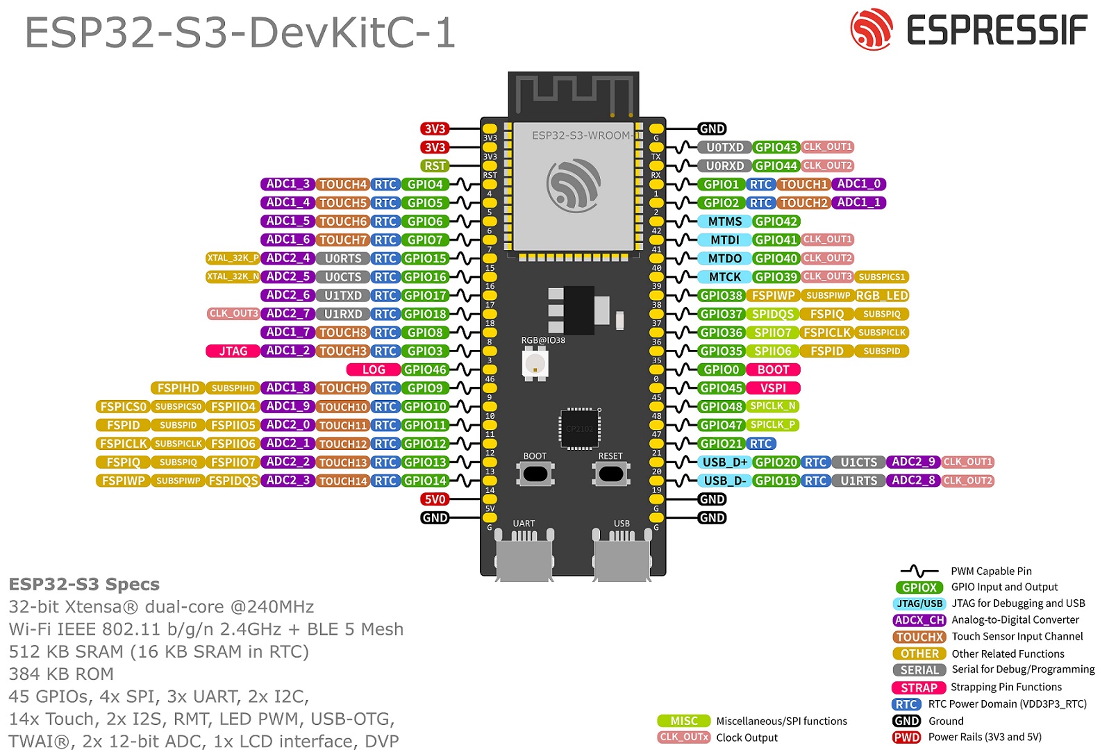 silk geyser
yup, thats the one
i think the 3v3 regulator is signitifcantly lowering the current to get the voltage up to 3 volts
so that is why its not getting enough current
and given that the 5v pin is outputing 2v, i think thats how much the board is being supplied
i've got no idea why
i was using a usb hub, but now im using a direct usb-c to usb-c cable
stable forge
that doesn't make sense. the 3.3v regulator is not a buck boost
silk geyser
🤷♂️
stable forge
I will be back in 45 minutes or so
silk geyser
alr
stable forge
silk geyser
alr
Looking at the schematic, the 5v pin from either USB connector goes through a diode to the 5V pin. Could you measure that again? On mine, I had to press a little harder to get a good reading on the 5v pin. I see 4.7V because of the Schottky diodes that select the higher of the two USB voltages.
stable forge
wise forum
Hello guys and gals. Where is the proper place to announce Arduino library?
I'v...
you might want to announce it in the Arduino forums if you think it's an improvement over the existing libraries.
wise forum
stable forge
you might want to announce it in the Arduino forums if you think it's an improve...
Hello danh,
- Arduino forums are overloaded with themes. If they split it in categories like "help me!1", "library announces" and "help with specific library" it would be a lot easier for everyone. There are no better places than Arduino's forums? (Ideally, a maillist for other developers.)
- I wrote it for myself and don't try to force everyone to use it. But I want it be reachable for everyone who wishes.
- Yeah. Adafruit's Neopixel. Just 3.5k lines of code. Still a lot better reading than FastLED. My code is here for reference: https://github.com/martin-eden/arduino_sketchbook/blob/master/libraries/me_Ws2812b/src/me_Ws2812b.cpp

GitHub
My experiments with Arduino platform. Code is ugly, unfinished, hackish and my C style is not formed yet. - martin-eden/arduino_sketchbook
leaden walrus
@wise forum info on registering a library is here:
https://github.com/arduino/library-registry
eternal cloud
wise forum
Hello danh,
1. Arduino forums are overloaded with themes. If they split it in ...
Coming to Adafruit discord to insult their code, and in the same breath demand of their employees that they promote your code instead, because it's ... shorter? lmao
pine bramble
Hey 🙂 Is there an alternative way to make the HUZZAH32 a MIDI device which can send via USB? I can't get the Adafruit_TinyUSB.h to work. I've also tried MIDI Library by Francois Best.
eternal cloud
pine bramble
Hey 🙂 Is there an alternative way to make the HUZZAH32 a MIDI device which can ...
The esp32 chip does not have native USB support, so I'm not sure you can have MIDI over USB, only UART or BLE.
This wing might be helpful: https://learn.adafruit.com/adafruit-midi-featherwing
pine bramble
eternal cloud
The esp32 chip does not have native USB support, so I'm not sure you can have M...
Thank you so much👍
wise forum
leaden walrus
<@376692202291593217> info on registering a library is here:
<https://github.com...
Thank you.
 narrow iron
I have two USB peripherals and I want them to talk to each other using the RP2040 USB Host. I'd like to use the USB A and USB C ports and not hard wire to the GPIOs.
Both of the devices do not supply 5VDC - so I'll be using a 3.7V batt on the RP2040 JST
I want the USB C port to be the host.
There is an example sketch in Arduino IDE called "serial_host_bridge" I think this is a good starting point, but I can't seem to get it to work.
Thoughts? Is what I'm describing above possible?
wise forum
eternal cloud
Coming to Adafruit discord to insult their code, and in the same breath demand o...
I came here to ask advice for good place to announce library. For example there is maillist for Lua. I thought there should be something similar for Arduino or Esplora. No offence to Adafruit, I appreciate their work on unifying sensors. Just a bit allergic to arguments "it's already done" (assuming it's taboo now).
wise forum
narrow iron
I have two USB peripherals and I want them to talk to each other using the RP204...
If there is related example then most likely it's possible.
eternal cloud
narrow iron
I have two USB peripherals and I want them to talk to each other using the RP204...
Are you using the Adafruit USB host feather ? https://www.adafruit.com/product/5723
Only the USB A can be host on this board
wise forum
It's demagogy. You are making false assertions what opponent said and then critique them. 3k lines source file is design smell for me. But it's out of scope. Regarding my question of place to announce new implementation I've got recommendation of Arduino's forum and link about adding lib to official repo. Let's close this discussion.
narrow iron
eternal cloud
Are you using the Adafruit USB host feather ? https://www.adafruit.com/product/...
Yes, using the USB host feather... got it, only USB A can be host.... TY!
 timid tapir
Hi all, I'm having some trouble getting an ssd1331 display up and running on my esp32 dev board (cp2102)
- Im using the adruino IDE
- I'm using the Adafruit_SSD1331 library (and I have adafruit_gfx lib installed as well)
- The code I'm trying to upload is just the the built-in example LCDGFX demo code
Pinout below:
SD1331 Pin ESP32
1 GND -> esp32 GND
2 VCC -> esp32 3.3v
3 SCL -> GPIO14
4 SDA -> GPIO13
5 RES -> GPIO15
6 DC -> GPIO05
7 CS -> GPIO04
Code uploads completely fine, but my display does not come on. I just don't have a fundamental understanding of where each pin should be given my esp32 is different than the esp8266 documented in the code. I presumed they should be the same but I'm not sure
eternal cloud
timid tapir
Hi all, I'm having some trouble getting an ssd1331 display up and running on my ...
What ESP32 board are you using ? The pins are most likely not the same, you need to check the board documentation.
timid tapir
I think its just a generic esp32 dev. Its made by AITRIP ESP-WROOM-32. I bought that one because I liked the convenience of the usbc. I've ran all my other sketches with it fine

I see that it says 4x SPI pins but I see VSPI and HSPI totalling to 8?
timid tapir
eternal cloud
What ESP32 board are you using ? The pins are most likely not the same, you nee...
See above
eternal cloud
timid tapir
I see that it says 4x SPI pins but I see VSPI and HSPI totalling to 8?
Yes, it has multiple SPI ports, you need to choose one and use its pins
like V mosi would be gpio23 and v sck gpio 18
#define mosi 13
#define cs   5
#define rst  9
#define dc   6```
do you have this in the example code you're trying to run ?But what does that correspond to on the display unit?
timid tapir
eternal cloud
```#define sclk 14
#define mosi 13
#define cs 5
#define rst 9
#define dc 6`...
yep its this one
eternal cloud
you need to connect the oled over an SPI connection , so sclk would be gpio18 for you, and mosi gpio23
chip select cs , reset rst and data dc are defined by you, how you connected the oled
they can be any digital pins
timid tapir
eternal cloud
you need to connect the oled over an SPI connection , so sclk would be gpio18 f...
So SCL from the oled goes to GPIO18? (VSPI_SCK)
eternal cloud
oh, wait, oled is on I2C ?
post a pic, please ?
timid tapir
 eternal cloud
ok, i see ...
so SCL on oled should go to vspi_sck gpio18 yes
SDA to gpio23 vspi_mosi
eternal cloud
only the definitions
timid tapir
yeah thats what i meant ok
eternal cloud
timid tapir
yeah thats what i meant ok
You might have to change the display init too, since it's using the default "&SPI" and I don't think this board has a default value
Adafruit_SSD1331 display = Adafruit_SSD1331(cs, dc, mosi, sclk, rst);
should work
timid tapir
Okay so display works but is showing some mess so Ill try that new init
Okay seems to work!
eternal cloud
Yay! 🙂
timid tapir
there's something funky going on with the refresh though
eternal cloud
timid tapir
there's something funky going on with the refresh though
If you're on a breadboard, make sure your connections are stable ... other than that, I'm not sure 😅
timid tapir
Could be the code cause at some point it becomes butter smooth and then back to some weirdness
Okay well now for the explanation part. How did you know that SCL is for the VSPI_SCK and SDA for VSPI_MOSI?
eternal cloud
timid tapir
Okay well now for the explanation part. How did you know that SCL is for the VSP...
I was looking in the library examples https://github.com/adafruit/Adafruit-SSD1331-OLED-Driver-Library-for-Arduino/tree/master/examples and they always label SDA-MOSI and SCL-SCK in code
I'm still not sure why these oleds come labeled with I2C names when they actually use SPI interface, but ... 🤷♀️
timid tapir
eternal cloud
I was looking in the library examples https://github.com/adafruit/Adafruit-SSD1...
Got it okay. I was just confused because code for me says SCLK and I had no itea SCLK and SCK is the same. Furthermore there is an HSPI_MOSI and HSPI_SCK so how did you know it wasnt those spi but vspi?
eternal cloud
oh, you can use HSPI if you want, like i said, you just need to pick one ... like you can't use mosi from H and clock from V
ESP32 chips have multiple SPI interfaces, and on your board, the pins are exposed for 2 of them ... so you choose which one to use
timid tapir
Theres no difference between H/V?
eternal cloud
nope
timid tapir
Okay I will try it see if there's any visual diff
Yup no difference as expected
Thank you for the assistance
timid tapir
eternal cloud
You might have to change the display init too, since it's using the default "&SP...
Does this affect performance though? Maybe I can define the &SPI so that it can run faster?
The display init we using rn is just the init for any pins
Or does it not matter because we are hooked up to the hardware spi pins
eternal cloud
timid tapir
Does this affect performance though? Maybe I can define the &SPI so that it can ...
it might ... you can declare an SPI object if you want and use that one in the init
timid tapir
eternal cloud
it might ... you can declare an SPI object if you want and use that one in the i...
Is there a way i can simply modify the existing SPI class?
eternal cloud
timid tapir
Is there a way i can simply modify the existing SPI class?
you just need to add your SPI pins as parameters in a SPI.begin( ); call
i just don't remember in what order 🤔
timid tapir
Cool ill try both thank you once again. If I may ask where you found that?
It seems like I must populate all 4 fields

But it doesnt work. Am I calling it in the right place?
eternal cloud
well, miso is not used for oled communication , but just take the pin name from the pinout (it doesn't matter if it's not connected) , and ss is your cs
and you should call it before the display init , just remember to swap back to &SPI
possibly need to do a pinMode (cs, OUTPUT); before SPI.begin()
timid tapir
I just want to double check, CS in my case is set with #define to 19. We pass that in
Adafruit_SSD1331 display = Adafruit_SSD1331(&SPI, cs, dc, rst);
and then in the setup
pinMode(19, OUTPUT);
SPI.begin(18, -1, 23, 19);
yeah unfortunately doesnt work
timid tapir
eternal cloud
possibly need to do a `pinMode (cs, OUTPUT);` before `SPI.begin()`
Seems like the SPI.begin() function already sets all the pinmodes and such as per documentation

Or that may be the wrong one since it takes no parameters 😂
eternal cloud
timid tapir
I just want to double check, CS in my case is set with #define to 19. We pass th...
you chose cs = 19 which is exactly the miso pin for vspi 😅
timid tapir
Okay yes. I was aware of that but figured it was okay since i set it to -1 (unused) in the code?
Shall i try a diff pin for cs/ss
eternal cloud
i think you need to specify the correct one to init the spi
timid tapir
Yeah I dont think SPI class works with esp32
I even tried using GPIO5 which is the natvie VSPI_SS pin
wise forum
timid tapir
Yeah I dont think SPI class works with esp32
Keep in mind that ESP boards has different pin numbering.
For example pin labeled "3" on Uno has code value 3. For esplora it's different integer and you may use "D3" to get it's value for your code.
eternal cloud
timid tapir
I even tried using GPIO5 which is the natvie VSPI\_SS pin
VSPI seems to be the default SPI on esp32 in arduino, so the example code should work with &SPI
https://github.com/espressif/arduino-esp32/blob/master/libraries/SPI/examples/SPI_Multiple_Buses/SPI_Multiple_Buses.ino
timid tapir
wise forum
Keep in mind that ESP boards has different pin numbering.
For example pin label...
Yep I was aware of that I just would have never known that I need to connect the SCL and SDA pins of the display to the MOSI and SCK of the esp32
timid tapir
eternal cloud
VSPI seems to be the default SPI on esp32 in arduino, so the example code shoul...
So that would be gpio18 & gpio 23 in my case yes?
 eternal cloud
timid tapir
So that would be gpio18 & gpio 23 in my case yes?
eternal cloud
timid tapir
So that would be gpio18 & gpio 23 in my case yes?
yep , 18 and 23
crisp hinge
Hi, what could cause such things? My code? It's rare and random.
 lethal yarrow
More likely either a brownout or data corruption on the control bus.
tardy iron
crisp hinge
Hi, what could cause such things? My code? It's rare and random.
can you provide more details about the circuit and wiring? are you using parallel communication, or going through an I2C "backpack" etc?
crisp hinge
tardy iron
can you provide more details about the circuit and wiring? are you using paralle...
using I2C
crisp hinge
lethal yarrow
More likely either a brownout or data corruption on the control bus.
"data corruption on the control bus" can be due to my code?
lethal yarrow
crisp hinge
"data corruption on the control bus" can be due to my code?
No. It would be due to your wiring, or the environment you are running it in.
tardy iron
crisp hinge
using I2C
the default character ROMs for a lot of those have some kana in the upper half of the space, so something that flips the high bits could produce that
also, there's a maximum speed that they'll accept input. ideally, the I2C module slows down its output to accommodate that, but going too fast is another possible source of corruption
tardy iron
crisp hinge
using I2C
i guess you could try adding delays between characters to see if that helps?
crisp hinge
what do you mean by "delays between characters" ? I don't understand
timid tapir
eternal cloud
yep , 18 and 23
Don't know why but it doesnt work
tame pollen
Would this be enough for powering a car that would use an Arduino Nano ESP32 as guidance computer with 2x DC motors and an ultrasonic sensor?
 north stream
tame pollen
Would this be enough for powering a car that would use an Arduino Nano ESP32 as ...
north stream
tame pollen
Would this be enough for powering a car that would use an Arduino Nano ESP32 as ...
Perhaps. It depends on how much power the motors draw, what type of AA cells you use, and how much runtime you need. Note that it will provide from about 7 to about 9 volts, so you may need some circuitry to regulate that down to whatever power supply voltage your Nano wants.
frozen crescent
tame pollen
Would this be enough for powering a car that would use an Arduino Nano ESP32 as ...
No, voltage drop when you start your motors will cause your ESP to brown out.
You need a buck-boost converter in the middle and even then AA-s don't store that much energy. If you can use a battery bank, that'd work better.
tame pollen
Got it ty
 vivid rock
frozen crescent
No, voltage drop when you start your motors will cause your ESP to brown out.
vivid rock
frozen crescent
No, voltage drop when you start your motors will cause your ESP to brown out.
depends on the motors.
I have done quite a few robots that use 4AA batteries as power source, no problems
vivid rock
tame pollen
Would this be enough for powering a car that would use an Arduino Nano ESP32 as ...
what motors do you plan to use?
tame pollen
vivid rock
what motors do you plan to use?
These two
 vivid rock
this is not very helpful, as there is no info about voltage and stall current.
but if they are of same type as the motors here:
https://www.adafruit.com/product/711
then the stall current is 500 mA per motor. Good quality rechargable NiMh AA battery should be able to handle.
Still, using a 2-cell Lipo is probably a better choice.

These are standard '130 size' DC hobby motors. They come with a wider operating range than most toy motors: from 4.5 to 9VDC instead of 1.5-4.5V. This range makes them perfect for ...
frozen crescent
vivid rock
depends on the motors.
I have done quite a few robots that use 4AA batteries as ...
I've tried something very very similar and it just wasn't reliable. The very least a buck-boost converter would be required.
vivid rock
well, it worked fine for me.
certainly a buck converter is needed to bring 9v down to something more reasonable to feed to the LDO on the board, but I didn't need a boost
plus, of course, a bulk capacitor (I used two 330uF)
but indeed, LiPo is much better choice
tame pollen
vivid rock
this is not very helpful, as there is no info about voltage and stall current.
b...
Okay thank you
timid tapir
On that topic of powering your project with LiPos how can I implement that sort of battery/bms which will charge over the usb on my esp32? Or would it be way easier to just buy another board like this one which has this battery connector and charging capabilities built in?
https://learn.adafruit.com/adafruit-huzzah32-esp32-feather/power-management

 wanton sedge
timid tapir
On that topic of powering your project with LiPos how can I implement that sort ...
wanton sedge
timid tapir
On that topic of powering your project with LiPos how can I implement that sort ...
You could look at the PowerBoost 500/1000 (500mA vs 1A charge rates) - this has all the protection needed for a single cell LiPo. But yeah personal preference, could also get a board that has similar built in.
PowerBoost 1000 Charger - https://www.adafruit.com/product/2465
PowerBoost 500 Charger - https://www.adafruit.com/product/1944

PowerBoost 1000C is the perfect power supply for your portable project! With a built-in load-sharing battery charger circuit, you'll be able to keep your power-hungry project ...

PowerBoost 500C is the perfect power supply for your portable project! With a built-in battery charger circuit, you'll be able to keep your project running even while recharging the ...
crisp hinge
crisp hinge
Hi, what could cause such things? My code? It's rare and random.
Would a voltage of 5.5V instead of 5V cause any issues?
As I said, it's random and rare
eternal cloud
crisp hinge
As I said, it's random and rare
Again... without details about your components, pictures of your circuit wiring, and possibly posting your code, nobody can say.
crisp hinge
eternal cloud
Again... without details about your components, pictures of your circuit wiring...
I sent a picture of the old wiring, now there is a flyback diode added, that's way better but not enough

it's due to the environment we are running it
eternal cloud
crisp hinge
That is not your wiring, that is a (hand drawn) schematic.
It's not even clear what microcontroller you're using, never mind other components, and you never changed the -12V, like dan said.
crisp hinge
I'm not the one who draw it, that's why it did't changed. We are using a TTGO LoRa32
eternal cloud
crisp hinge
I'm not the one who draw it, that's why it did't changed. We are using a TTGO Lo...
Ok. But that schematic is still almost irrelevant (**AND **incorrect).
Without pictures and details of your actual circuit, nobody can check and tell you what could be wrong with your actual circuit.
crisp hinge
eternal cloud
Ok. But that schematic is still almost irrelevant (**AND **incorrect).
Without ...
Ok, but is it necessary to answer to this question ?
Would a voltage of 5.5V instead of 5V cause any issues?
eternal cloud
crisp hinge
Ok, but is it necessary to answer to this question ?
> Would a voltage of 5.5V ...
**Yes **
north stream
timid tapir
On that topic of powering your project with LiPos how can I implement that sort ...
All the Feathers (including that one) have charging capabilities built in.
north stream
crisp hinge
it's due to the environment we are running it
You may need to add some power filtering/decoupling and/or shielding, depending on whether the problem is conducted or radiated.
timid tapir
wanton sedge
You could look at the PowerBoost 500/1000 (500mA vs 1A charge rates) - this has ...
Thanks! Do you know if I would I be able to charge the battery via the esp32 usb port with those powerboosters? (I want a single port to both charge and edit the bin if needed)
timid tapir
north stream
All the Feathers (including that one) have charging capabilities built in.
Yup I got that which is why I wish I knew about it earlier cause it’s nice to have all that built-in
eternal cloud
timid tapir
Thanks! Do you know if I would I be able to charge the battery via the esp32 usb...
No, both of those charge the battery from their input usb connection, and boost the lipo voltage to provide 5 V output
eternal cloud
timid tapir
Thanks! Do you know if I would I be able to charge the battery via the esp32 usb...
There is also this charger (NOT a booster) https://learn.adafruit.com/adafruit-microlipo-and-minilipo-battery-chargers/pinouts
that you could use with a custom made usb plug to extend the usb data lines from the charger to your board, but this is kinda hacky and wouldn't recommend it unless you know what you're doing 😅
 haughty plover
can please anyone tell me how i can do this https://youtu.be/WBE8IZFu55Q?si=GcFO2DWD9xIrT_B9 ?

messing with a micro-controller manufactured by adafruit! this one is called a circuitboard playground express. i use arduino, max MSP, and VCV rack to design the controller to get it to look/sound like this.
 gilded swift
haughty plover
can please anyone tell me how i can do this https://youtu.be/WBE8IZFu55Q?si=GcFO...
gilded swift
haughty plover
can please anyone tell me how i can do this https://youtu.be/WBE8IZFu55Q?si=GcFO...
Please don’t post in multiple channels, pick one place and let someone respond.
haughty plover
ok sorry
gilded swift
It’ll take time as basically everyone here is a community member and helping when they have time. Rest assured though, with that being an Adafruit project there is probably a learning curve guide to help you
haughty plover
ok
gilded swift
Oh wait, perhaps it isn’t Adafruit but uses Adafruit stuff
gilded swift
haughty plover
ok
This learn guide will help you get started with MIDI and should hopefully give you the basics to get started: https://learn.adafruit.com/cpx-midi-controller

Adafruit Learning System
Using CircuitPython to turn the Circuit Playground Express into a USB MIDI controller or a simple MIDI-enabled synthesizer.
haughty plover
ok ty
gilded swift
Circuitpython will probably be easier to get the basics under your feet first. They appear to use Arduino which might make it more challenging
 limpid drift
how to get mpython programed with thorney to esp32
stable forge
limpid drift
how to get mpython programed with thorney to esp32
we don't have much experience installing micropython with thonny. See https://randomnerdtutorials.com/getting-started-thonny-micropython-python-ide-esp32-esp8266/ for instance
 magic vine
i'm using the adafruit st7735 library and i was wondering if it would be possible to manually refresh the display? like draw multiple things and only display when done. currently it draws to the screen after every draw call. im using an esp32-wrover-b that had a micropython firmware pre-installed which let me enable and disable the sync, so i could only refresh manually. does the adafruit library have a function like this?
frozen crescent
magic vine
i'm using the adafruit st7735 library and i was wondering if it would be possibl...
in general what you want is called vsync, if that's not available you just have to structure your code in a way that does all the draws at the same time
magic vine
i am drawing everything at the same time
tft.fillScreen(ST77XX_BLACK);
tft.fillRect(playerX, 0, PADDLE_WIDTH, 4, ST77XX_WHITE);
tft.fillRect(botX, tft.height() - 4, PADDLE_WIDTH, 4, ST77XX_WHITE);
tft.fillRect(ballX - BALL_RADIUS, ballY - BALL_RADIUS, BALL_RADIUS * 2, BALL_RADIUS * 2, ST77XX_WHITE);
if i run fillScreen, that gets drawn to the screen instead of a buffer and waits until its done, then moves to the next function
magic vine
https://github.com/vjmuzik/Adafruit_GFX_Buffer i found this library which works perfectly and is what i needed
GitHub
This library combines an Adafruit_GFX based display object and a GFXcanvas16 object into one. - vjmuzik/Adafruit_GFX_Buffer
 mossy fox
Hi guys,
I'm currently working on a POV display project using DotStar LEDs and the Adafruit_Dotstar class (https://github.com/adafruit/Adafruit_DotStar/blob/master/Adafruit_DotStar.cpp)
I need the fastest possible way to update my Dotstars. I'm using SPI at the maximum freq. of 32 MHz. The thing that takes the most time is the show() function in the Adafruit_DotStar.cpp.
I already changed it to get a bit more speed from it. Changes include:
- instead of making an SPI transfer() call for each pixel, I calculate every pixel using a buffer and then only do one call of transfer().
- pre calculating the brightness of the pixels and store everything inside a scaledColors array instead of doing the math inside the show() function.
Using the maximum SPI frequency of 32 MHz gives me a total time of roughly 1ms to call show() on my 128 LED strip.
I was wondering if there is any possible way to get even more speed out of this. I can post the code of my show() method if anyone is interested.
Thanks! 🙂

GitHub
Contribute to adafruit/Adafruit_DotStar development by creating an account on GitHub.
 fierce phoenix
(I guess I also ask here about stuff like Bluetooth microcontrollers)
Can you program the adafruit feather m0 for instance to skip ahead in a track by a couple seconds?
And also shuffle the music queue
north stream
fierce phoenix
(I guess I also ask here about stuff like Bluetooth microcontrollers)
Can you pr...
Uh, probably? It depends on what the source of the music is.
eternal cloud
fierce phoenix
(I guess I also ask here about stuff like Bluetooth microcontrollers)
Can you pr...
I think you missed the channel, you were over in https://discord.com/channels/327254708534116352/330406777009209346 😛 This is the Arduino channel.
And for most music players, the left and right arrows work as seek through the track, so you can just send HID codes for arrows. For shuffle, you probably need to create a key combination on your computer, and send that from the feather.
fierce phoenix
i switched here since i felt like arduino was more appropriate for a microcontroller specific question
and i hope the seek through the track indeed works because it'd wanna stream my music from the fiio r7's own built in music player
just easier to use then windows imo
eternal cloud
This channel is for official Arduino boards and / or programming in arduino language
fierce phoenix
pardon me if i'm wrong, but wouldn't an arduino microcontroller board be the best option for programming a device to add media controls to said device
eternal cloud
fierce phoenix
pardon me if i'm wrong, but wouldn't an arduino microcontroller board be the bes...
Arduino is a company.
They make microcontroller boards (like the Uno, Leonardo, etc, I'm not up to date with all their products)
and also developed a programming language - and were very "helpful" with naming it Arduino as well 🤣
Not all microcontroller boards are Arduino (see above the Adafruit feather m0)
And I was under the impression that you wanted to code in CircuitPython (i might be wrong 🤷🏻♀️)
fierce phoenix
oohh makes sense
fierce phoenix
eternal cloud
And I was under the impression that you wanted to code in CircuitPython (i might...
and i hosently don't know, i'll probably just buy the cheapest and see from there on
stable forge
fierce phoenix
and i hosently don't know, i'll probably just buy the cheapest and see from ther...
Buying the cheapest thing often means you spend more time getting it to work. Consider that. If you want to try CircuitPython buy a CircuitPython-compatible board.
Before buying, ask for feedback on your choice.
 turbid iris
Does the adafruit boards package support the new V2 Arduino IDE? If not i'll switch to the older IDE.
stable forge
turbid iris
Does the adafruit boards package support the new V2 Arduino IDE? If not i'll sw...
Yes, it's fine, I use the 2.x.x IDE all the time.
 opal turret
Hi. Is there an alternative way to supply power to this relay that does not involve batteries, but rather a plug-in solution?
 eternal cloud
opal turret
Hi. Is there an alternative way to supply power to this relay that does not inv...
eternal cloud
opal turret
Hi. Is there an alternative way to supply power to this relay that does not inv...
That doesn't look like supplying power to the relay, it's connected to the relay outputs.
You can use something like this for a 2.1 plug power supply https://www.adafruit.com/product/368
opal turret
eternal cloud
That doesn't look like supplying power to the relay, it's connected to the relay...
Good catch. Thank you very much.
 tame raptor
#include <DHT.h>
#include <DHT_U.h>
#include <LiquidCrystal_I2C.h>
#include <DHT.h>
#include <DHT_U.h>
#include <dht.h>
#include <Wire.h>
#include <LiquidCrystal_I2C.h>
LiquidCrystal_I2C lcd(0x27, 16,2);
dht DHT;
#define DHT11_PIN 4
void setup(){
lcd.begin();
}
void loop()
{
int d = DHT.read11(DHT11_PIN);
lcd.setCursor(0,0);
lcd.print("Temp: ");
lcd.print(DHT.temperature);
lcd.print((char)223);
lcd.print("C");
lcd.setCursor(0,1);
lcd.print("Humidity: ");
lcd.print(DHT.humidity);
lcd.print("%");
delay(1000);
}
anyone know whats wrong with this code?
it's for a weather station btw
livid osprey
tame raptor
#include <DHT.h>
#include <DHT_U.h>
#include <LiquidCrystal_I2C.h>
#include <D...
Hard to diagnose without the errors you’re getting, but you have three separate dht header files included there, which is almost definitely unnecessary at best, and interfering with each other at worst.
What errors are you getting, and where are you sourcing the three libraries?
Also, you have some included files twice.
tame raptor
error: 'dht' does not name a type
dht DHT;
error: no matching function for call to 'LiquidCrystal_I2C::begin()'
error: expected primary-expression before '.'
tame raptor
livid osprey
What errors are you getting, and where are you sourcing the three libraries?
I found this code online, he didn't give the libaries with it
so im kinda stuck rn
😅
stable forge
unrelated to your code, but note that there are much better sensors available: https://learn.adafruit.com/modern-replacements-for-dht11-dht22-sensors
stable forge
here's our guide. Maybe try our example instead: https://learn.adafruit.com/dht/using-a-dhtxx-sensor-with-arduino
is this on a classic Arduino?