#help-with-audio
1 messages · Page 11 of 1
 pale plume
pale plume
pale plume
I managed to get sample-perfect alignment between adjacent sounds, but not by polling playing.
Instead, since my sounds are mono, I used the right channel to carry a square wave and connected its pin to another pin configured with a counter.
Polling for a change on the counter is somehow more precise than polling playing.
There seems to be a 2-sample delay (regardless of sampling rate!) between the falling edge of the square wave and the actual start of the new sound, but it's easy to advance the square wave by 2 samples to compensate.
pale plume
I'm observing that the quiescent_value argument of audioio.AudioOut only seems to be used at startup; otherwise the DAC seems to hold whatever value it was given last. Is that expected?
 muted wind
does anyone have a wiring guide for mini audio fx board to the max98357a amp?
https://www.adafruit.com/product/2342
to
https://www.adafruit.com/product/3006

Would you like to add audio/sound effects to your next project, without an Arduino+Shield? Or maybe you don't even know how to use microcontrollers, you just want to make a sound play ...

Listen to this good news - we now have an all in one digital audio amp breakout board that works incredibly well with the Raspberry Pi! If you're looking for an easy and low cost ...
 odd oasis
muted wind
does anyone have a wiring guide for mini audio fx board to the max98357a amp?
ht...
odd oasis
muted wind
does anyone have a wiring guide for mini audio fx board to the max98357a amp?
ht...
Not sure what your goal is here, since one of these modules is a soundboard with an amplified output, and the other is an I2S-to-analog amplified output. You probably only want to use one or the other...?
 random bone
muted wind
does anyone have a wiring guide for mini audio fx board to the max98357a amp?
ht...
random bone
muted wind
does anyone have a wiring guide for mini audio fx board to the max98357a amp?
ht...
https://learn.adafruit.com/adafruit-audio-fx-sound-board/pinouts#audio-outputs-1386548-12 @odd oasis is right, you don't want to use an I2S-input amplifier, you want an analog-input amp (of which we have several)
muted wind
random bone
<https://learn.adafruit.com/adafruit-audio-fx-sound-board/pinouts#audio-outputs-...
ok, thanks
muted wind
odd oasis
Not sure what your goal is here, since one of these modules is a soundboard with...
it seems that way, yes
muted wind
random bone
<https://learn.adafruit.com/adafruit-audio-fx-sound-board/pinouts#audio-outputs-...
would this work as an amp with the wav/ogg board i mentioned?
https://www.adafruit.com/product/2130

This super small mono amplifier is surprisingly powerful - able to deliver up to 2.5 Watts into 4-8 ohm impedance speakers. Inside the miniature chip is a class D controller, able to run ...
random bone
it is only mono, and the wav/ogg board will do stereo. Do you want stereo?
muted wind
not necessary, its just a sound effect for a toy basically
random bone
do you already have the 2342 board, or you're trying to decide what to buy?
muted wind
yes i have the 2342 board already
random bone
products 987, 1552, 1712 are stereo. 2210 and 2217 are like the 2342 board but with a built-in amp
muted wind
thanks
random bone
Adafruit Industries, Unique & fun DIY electronics and kits : Amplifiers/Sound - Tools Gift Certificates Arduino Cables Sensors LEDs Books Breakout Boards Power EL Wire/Tape/Panel Components & Parts LCDs & Displays Wearables Prototyping Raspberry Pi Wireless Young Engineers 3D printing NeoPixels Kits & Projects Robotics & CNC Accessories Cosplay/...
muted wind
2342 supports 44100 hz max wav file sample rate?
random bone
muted wind
2342 supports 44100 hz max wav file sample rate?
from the product description: High Quality Sound - You want 44.1KHz 16 bit stereo? Not a problem! The decoding hardware can handle any bit/sample rate and mono or stereo https://www.adafruit.com/product/2342
 lethal slate
Maybe the description should say "any commonly used bit or sample rate."
muted wind
random bone
from the product description: _High Quality Sound - You want 44.1KHz 16 bit ster...
thanks. wasn't sure if lower sample rates would improve loop speed
 twilit grotto
Total amateur but I feel like I'm close to getting the audio shield working with a teensy 4.1. Headphones pop when powering on, so I think the shield is receiving power from the teensy but none of the examples produce sound. Any sketches to test properly soldered pins??
 glacial spruce
Presumably some of the example sketches that come with the Teensy Audio Library
 languid pollen
Hi, im new here, i wonder if anyone has a good example to control volume (audio pc) from an analog potentiometer, is it possible? i couldn't found much.
glacial spruce
It's possible. I can think of two approaches offhand: one is the direct approach of just using the potentiometer as a voltage divider between the computer and external speakers. If you actually want to control the volume in software, you could hook the potentiometer to a USB capable microcontroller and program it to send USB commands to change the system volume.
odd oasis
Software control is much easier with a rotary encoder, due to the ease of access to the vol+/- keys. The analog pot, on the other hand, probably wants direct access to setting a value for the volume level, which is a little more involved. I can imagine that's probably the reason why you can't find any good software-controlled examples...
For the external option, I did see a cute instructable here: https://www.instructables.com/DIY-External-Volume-Control/
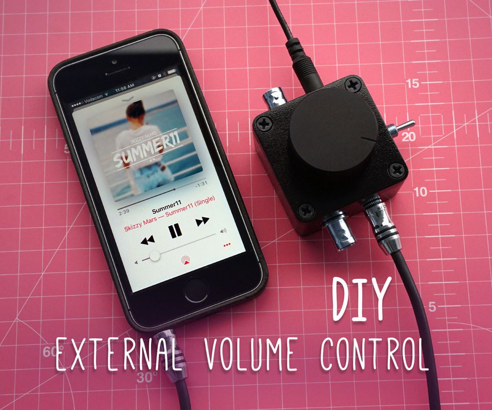
Instructables
DIY External Volume Control: Phwoar, volume knobs. Arguably, the best kind of knob. And certainly the most enjoyable part of any decent audio gear - you can tell a lot about an amplifier or DAC by the texture and rotation quality of it’s primary enloudener.But there&rsquo…
 lethal fox
I'm not sure where to "poke". I'm using the Stereo 20W Class D Audio Amplifier - MAX9744 (https://www.adafruit.com/product/1752) with the Adafruit I2S Stereo Decoder - UDA1334A Breakout (https://www.adafruit.com/product/1752) and I'm getting a "popping" sound from low frequencies. Possibly < 100Hz. Any ideas on how I can figure out what is causing this?

Pump up the volume with this 20W stereo amplifier! This slim little board has a class D amplifier onboard that can drive 2 channels of 4-8 ohm impedance speakers at 20W each. Power it with ...
glacial spruce
Could it be clipping?
 lime yew
Seems likely
 lethal fox
I was playing Spotify and realized I had the base on it's EQ "excessively" enhanced. So, backing off "fixed" it.
muted wind
Does anyone know what the default volume level is for the fx sound boards like https://www.adafruit.com/products/2210 ? There are volume level pins, but I'd like to avoid having to connect them

Would you like to add audio/sound effects to your next project, without an Arduino+Shield? Or maybe you don't even know how to use microcontrollers, you just want to make a sound play ...
lethal fox
So the UDA1334 breakout has pins to set the input format. I would like to try 24bps but I don't know what the format of LSB is versus what is coming across in I2S? Can someone explain? Thank you!
https://www.adafruit.com/product/3678

This fully-featured UDA1334A I2S Stereo DAC breakout is a perfect match for any I2S-output audio interface. It's affordable but sounds great! The NXP UDA1334A is a ...
odd oasis
LSB is short for Least Significant Bit, which usually indicates the smallest "digit" of your numeric data is being transmitted first.
 vague epoch
i'm new to audio stuff, and i was wondering how exactly to approach this. let's say i have a microphone which is analog output (3.5mm, in this case i would cut the wires and strip it) and hook up the wires to the ADC of an rp2040 or something. how would i take that and turn it into useful audio? is my understanding of hooking up the microphone via the ADC correct? thanks
vague epoch
just found out that my required sample rate would be WAYYY higher than the onboard ADCs, maybe i should go with something more like this: https://www.adafruit.com/product/4384 ?

This audio adaptor lets you easily add high quality 16 bit, 44.1 kHz sample rate (CD quality) audio to your projects with Teensy 4.0 (Rev D). It supports stereo headphone and stereo ...
 spring briar
What is the max sample rate of the rp2040's ADC then?
vague epoch
hm wait maybe it would be enough, i mentally mixed up the ADC of the rp2040's ADC and the other ADCs available on adafruit
i guess i would have to check if the code i'm running would give the ADC enough cpu time to be fast enough
glacial spruce
The code might be fast enough, but the microphone produces a low level signal, which wouldn't give good data from an ADC without some amplification.
 hybrid trail
It might be worth considering what the existing audio ecosystem is like for either board. I believe there's a substantial audio community around the teensy, so it may be easier to find premade expansion boards and applicable software
you might also consider a microphone with a digital output such as this one: https://www.adafruit.com/product/3421
vague epoch
i ended up deciding on the teensy
vague epoch
hybrid trail
you might also consider a microphone with a digital output such as this one: htt...
for this project i had to use a specific mic (contact mic for guitar) but i appreciate the suggestion
i would like to add that neopixel support on teensy is awesome! been having a great time with my feather and teensy :)
hybrid trail
The teensy is a really cool board, I don't think you'll be disappointed 🙂
the pico is pretty cool too, but the teensy has an insane amount of horsepower
lethal slate
import random
import time
import board
import digitalio
import remidi
from audiocore import WaveFile
from voice import VoiceI2S
from audiomixer import Mixer

bpm = 90
ts = 60/bpm * 1/4
last_tick = 0

def load_sounds(files):
    wavs = []
    for f in files:
        wavs.append(WaveFile(open(f, "rb")))
    return wavs

kick,snare = load_sounds(["/sounds/00.wav","/sounds/01.wav"])

led = digitalio.DigitalInOut(board.LED)
led.direction = digitalio.Direction.OUTPUT

# Metro M4
voice = VoiceI2S(board.D3, board.D9, board.D8)
mixer = Mixer(voice_count=2, channel_count=2, sample_rate=44100)
mixer.voice[0].level = 0.1
mixer.voice[1].level = 0.1
voice.dac.play(mixer)
step = 0

if __name__ == "__main__":
    while True:
        now = time.monotonic()

        if ts <= now - last_tick:
            last_tick = now
            step = (step + 1) % 8
            if step == 0:
                led.value=True
                mixer.voice[0].play(kick)
            if step == 1:
                led.value=False
                mixer.voice[0].play(snare)
            if step == 2:
                mixer.voice[0].play(kick)
            if step == 3:
                mixer.voice[0].play(snare)
            if step == 4:
                mixer.voice[0].play(kick)
            if step == 5:
                mixer.voice[0].level=0.06
                mixer.voice[0].play(kick)
            if step == 6:
                mixer.voice[0].level=0.1
                mixer.voice[0].play(snare)
            if step == 7:
                mixer.voice[0].play(snare)

        time.sleep(0.01)
 hearty cypress
Has anyone added a slider on/off switch to a speaker from a 'prop maker feather wing'? Anything pitfalls I should be aware of?
 dull basalt
Why would you do that?
hearty cypress
The idea behind it would be if I wanted to use my prop with just lights - and not audio - I could cut off the sound with a slider switch. Like having a slider switch between the battery and feather.
 lofty star
is it an amp type speaker or just a buzzer?
hearty cypress
the 'mini oval' 8ohm/1watt
https://www.adafruit.com/product/3923

Hear the good news! This wee speaker is a great addition to any audio project where you need 8 ohm impedance and 1W or less of power. We particularly like ...
lofty star
if it only has power and ground i wouldn't imagine you would find any particular trouble..... but i am no expert xD
hearty cypress
Cool.. I figured as much not, but wasn't quite sure if the prop-maker feather would flip out if the power was cut and it tried to play audio (lazy coding option here).
dull basalt
Well I'd guess that the newer circuits are tolerant of switching off a speaker load. You are not supposed to do it to vintage gear, as many of their amps require a load.
So we used an L Pad there.
Rat Shack used to sell them.
Big wire-wound rheostat like thing. Wall mounted on a switchplate form-factor.
hearty cypress
Ha! Yeah, hopefully nothing that massive. Just sounds when the prop moves based on the feather info.
dull basalt
radio shack L-pad 40-978
Produced many images in google search.
I bought one because, you know, I had money in my pocket and I was tired of walking past it every time I went to Rat Shack.
hearty cypress
heh.. I don't believe I have had seen one in the wild.
dull basalt
Most of these circuits work in a similar way: you present a constant load (pretty much) to the last amplifier stage.
Then tap the output.
lofty star
...cause our amps go to eleven
dull basalt
heh
There's a T-pad shape I've used in cables.
and the H-pad is balanced I think.
 carmine fern
I'm trying to play audio on the RP2040 in CircuitPython. I'm using a WAV file with the appropriate compression for CircuitPython. I'm using audiopwmio, as audioio isn't on the RP2040. When I run the code, the audio plays for a few seconds (the amount of time is not consistent, seems to be anywhere from less than a second to about 10 seconds) and then stops. It doesn't even run any of the code after the call to play the audio, it just says Code done running even though there is more code.
What can I do to avoid this?
 echo hedge
@carmine fern use the absolute latest builds. dan has been bug hunting audio playback on rp2040
random bone
carmine fern
I'm trying to play audio on the RP2040 in CircuitPython. I'm using a WAV file wi...
yes, the audio is messed up. It appears that it conflicts with display and other DMA. Still debugging this. If you don't need a display, you could try turning it off. Sorry, this has been hard to debug. Just playing tones with PWMOut will work, but not arbitrary wav files
carmine fern
random bone
yes, the audio is messed up. It appears that it conflicts with display and other...
I’m not using a display
random bone
are you using neopixels?
I did fix some things which are in "Absolute Newest", but they are not all the problems.
carmine fern
I'm still having the issue on the "Absolute Newest"
I am using neopixels, but they are kind of an important part of the project...
lethal fox
I have an ESP32 -> UDA1334A breakout -> MAX9744 20W amp configured and working with the default I2S (16bps 44.1kHz) configuration but I would like to configure it for the LSB 24bps configuration but I'm not sure of a couple things:
-
What conversion do I need to do to the I2S 16bps (PCM?) data before handing it to i2s_write to make it LSB compatible for the UDA1334A?
-
I've attached SF0 and SF1 to pins on the ESP32 (33, 32) and I've set them to both to LOW (low/low == I2S standard) and now I just hear noise on the output? I hear noise no matter what I do, even if there is no data coming from the I2S lines. Why is this? What should I connect those pins (SF0/SF1) to?
lethal fox
I must have asked the impossible question...
 solemn flint
lethal fox
I must have asked the impossible question...
solemn flint
lethal fox
I must have asked the impossible question...
Heh heh, probably not impossible, but just over the line of, "Meh, that sounds like it's going to take too long to figure out from the datasheet..."
lethal fox
The back of the UDA1334A tells how to switch the mode to 24bps LSB... I just don't know what the format of that data is. If it's simply a byte swap of the I2S (standard) data then it should be easy to do. The issue with SF0/SF1 are probably just the wrong voltage or something or other.
 opaque lion
Hi, I just got the auto gain electret microphone (https://www.adafruit.com/product/1713), and I have tried to connect it to an arduino copy nano (3v3 to vcc, gnd to gnd , A0 to out) and I can't seem to get a noise to change the reading on the analogue pin, apart from background electrical noise. I have linked an image of my serial output graph, no matter how much sound I make, this stays consistent, can anyone help? Do I need to put in a cap?
(This will be used as an input for an argb strip, where higher mic level = more leds on)
 odd oasis
opaque lion
Hi, I just got the auto gain electret microphone (https://www.adafruit.com/produ...
odd oasis
opaque lion
Hi, I just got the auto gain electret microphone (https://www.adafruit.com/produ...
Maybe try pulling the gain pin to ground? If that doesn't work, try connecting vcc to a battery pack instead?
opaque lion
Thanks for the hints, I have it fixed now (for some reason it didn't work on 3v3 and only 5v) Thanks for the help anyway!
 elder gyro
would a MAX98357A blow up if the vin and ground were swapped with 3.3v?
glacial spruce
Probably?
elder gyro
Well I think I killed mine lol time to purchase another
elder gyro
If I wanted to use two speakers with I2S, would the UDA1334A in conjunction with the TPA2012 be a good match?
 hardy vault
has anyone tried to get .wav output on the macropad speaker? i'm not finding a lot in the docs about it yet.
(from circuit python)
i did find autiobusio.I2Sout, but the sample uses pins that the macropad doesn't have. and the macropad doesn't have audioio where i could just use the .SPEAKER pin.
lethal slate
        # Play a specified file.
        self.stop_tone()
        self._speaker_enable.value = True
        with audiopwmio.PWMAudioOut(
            board.SPEAKER
        ) as audio:  # pylint: disable=not-callable
            wavefile = audiocore.WaveFile(open(file_name, "rb"))
            audio.play(wavefile)
            while audio.playing:
                pass
        self._speaker_enable.value = False
from https://github.com/adafruit/Adafruit_CircuitPython_MacroPad/blob/main/adafruit_macropad.py
Or use the macropad library and call play_file(filename).
hardy vault
OK, thanks. Didn't find the most obvious one. 🙂
 jade cargo
I have a midiplus usb midi host. It works fine with a few off the shelf midi controllers that use usb midi and it effectively routes those messages to din 5 midi. My issue is it doesn't output midi messages from either the neotrellis m4 or the macropad when using usbmidi. If I plug in either of those devices using usb to an ipad or to a pc they are recognized just fine and send midi over usb just fine. My issue is I need to use the host because I want din5 midi. Is there any reason why a circuitpython device running usbmidi code wouldn't work with a usbmidi host. Might this have something to do with 3.3v logic. Has anybody had any success using circuitpython devices with a usbmidi host and if so what brand. Is it possible to send midi over uart using the stemma port on the macropad or is that stricly for i2c. I am open to suggestion for din 5 midi out.
hardy vault
OK, got something from the macropad... But not recognizable audio. I know support is pretty limited with such a small "speaker"... any suggestions for audio format to get the best results? Currently 16bit signed .wav
Just a bunch of crackling
hardy vault
After further testing - sometimes just a crackle, sometimes a short crackle then recognizable sound, sometimes a longer crackle that is about the same length as the .wav. occasionally play_file never returns.
glacial spruce
I don't know offhand, but I'd suggest making up a few test files in likely formats.
lethal slate
Which CircuitPython build are you running (check boot_out.txt).
You'll want the latest build from S3.
Dan and Kattni have been working on 'crunchy' audio issues with the RP2040 (see #circuitpython-dev ).
hardy vault
i'm still on alpha 5. will try latest tomorrow and see what happens. thanx!
 round dew
Is my understanding correct that the 3v port on the arduino nano is just for output? i.e. I can't power the board on 3.3v?
 lethal slate
Try #help-with-arduino .
round dew
lmao my bad I misread "audio" for "arduino"
 urban widget
How important is a correct sinus wave for an old audio op amp
glacial spruce
That's normally only needed if you're doing something for distortion measurements.
urban widget
Okay, wanted to make a mobile party, so I don't need an expensive pure sine wave inverter
glacial spruce
Ah, you want to use the audio amplifier as a substitute for an AC power supply?
 ivory junco
Hello where do i go for adafruit fx sound card help
lethal slate
What can we help you with?
 late reef
Heeheehee 😁 while I know finding the parts and assembling it will be quite an uphill climb, the possible end result of my own functioning synth was just too good to pass up 😁 thank goodness I already have a scope 😅

 glacial spruce
I've eyed that thing too, thinking I might have to re-create some of the parts somehow. However, I'm still working on a thyratron synthesizer which has similar parts availability challenges.
late reef
glacial spruce
I've eyed that thing too, thinking I might have to re-create some of the parts s...
When doing a trash pickup recently I scooped up a Sanyo tape deck that has some sweet Japanese germanium transistors in it, would sure be cool if they fit in this design 😅 I Think they’re a decade apart tho
late reef
glacial spruce
I've eyed that thing too, thinking I might have to re-create some of the parts s...
I’m wondering if I can use an arduino to replicate some of the ICs if I truly can’t find em 🤔 seems like the headphone amp and op amp are the tough ones
glacial spruce
There are reasonable swaps for the op-amp, I'd just breadboard a headphone amp.
I have an assortment of germanium transistors, for repairing old Heathkit radios, Lectron sets, and the like.
late reef
Since germanium conducts at 1/3 vs the 1/2 of silicon, I’ve heard that it’s really good for overdrive and fuzz because it can saturate the signal more before hitting unity
glacial spruce
I also have some really old OCP-71 germanium transistors, which I bought because they're intended as phototransistors and have clear housings so you can see the innards.

Magnified, you can see how primitive they are
 late reef
Whoa!!! Super cool!! Definitely easy to see the link to vacuum tubes when it’s see thru and made that simply
glacial spruce
I intend to try hooking one up to see how it sounds
I also have some even older technology 2N110 point contact transistors. Weirdly, they were manufactured up to around 1970 (presumably as spares) even though they had been hopelessly obsolete for decades at that point.
Naturally I want to see what they sound like (I'm guessing noisy and crackly)
late reef
glacial spruce
I also have some even older technology 2N110 point contact transistors. Weirdly...
Hey, that could be desirable for people trying to recreate “old time radio” style interference for podcasts or vintage style productions 🙂 ground hum doesn’t quite cut it when you’re trying to recreate the “Lucky Strike Radio Hour” 😂😝
late reef
Green pic is one I took of the unit, but the unit had silver ones as well, both have same part number but some are sanyo and some are Toshiba - looks like we have a jellybean 🙂 guess now I’ll just have to compare the specs and see if it’s anywhere close to what the xoxbox design requires 😅 guess I could always make a “fuzz circuit” as an FX send 🙂


 nimble meadow
Hi. I’m trying to find the right gear to build toys for my son. I’d like to program simple blinking led patterns and play basic mono audio. Think the level quality level of a $10 toy fire truck with lights/sirens. The MP3/wav trigger and music maker sorts of options seem overkill for me, but maybe that’s just how much more it is for consumer quantities in dev board form? Are there ways to get a small speaker to play basic sound files with just a microcontroller? possibly with some cheap discrete ICs? I’d like to build a ton of these for him so trying not to over spec…
odd oasis
Sounds like a single channel true analog output will do the trick then. https://www.adafruit.com/product/4600?gclid=EAIaIQobChMI9MSt2aWX8gIVhozICh1ItAWrEAQYAyABEgI_7vD_BwE
What a cutie pie! Or is it... a QT Py? This diminutive dev board comes with our favorite lil chip, the SAMD21 (as made famous in our GEMMA M0 and Trinket M0 boards).This time it comes with ...
https://www.adafruit.com/product/3500 any of the m0 boards should have the true analog you need at a price you’re probably interested in

The Adafruit Trinket M0 may be small, but do not be fooled by its size! It's a tiny microcontroller board, built around the Atmel ATSAMD21, a little chip with a lot of power. We ...
glacial spruce
A simple microcontroller can make sounds like a siren or basic tone melodies, which isn't the same as playing sound files, but might be sufficient.
spring briar
You can play basic 8-bit wav files with an Arduino but you'll need an amplifier too.
nimble meadow
Appreciate the tips!
glacial spruce
@late reef In case you're curious, this is the partially completed thyratron synth board.
 late reef
glacial spruce
<@!790806321699487795> In case you're curious, this is the partially completed t...
late reef
glacial spruce
<@!790806321699487795> In case you're curious, this is the partially completed t...
Holy voltage, Batman!! 😱 that’s gonna have some over-the-top crunch!
Is the little patch bay looking thing on the right for adding resistors for fine tuning each note?
glacial spruce
I think so: the thyratron tube oscillator is notoriously non-linear, so a lot of tweaking is required for a well tempered scale.
Huh, apparently only 13 were made: https://encyclotronic.com/synthesizers/metasonix/pt-2-tubestation-r1513/

Encyclotronic
Monophonic rackmount vacuum tube synthesizer. Used single VCO with 2D21 thyratron, EF86 twin-t filter, EF86 VCA. Minimized version of PT-1, without the MIDI interface (accepts Hz/V CV from a Kenton or other MIDI/CV interface instead). 2U EIA rack cabinet. Original retail price $950. Only 13 pieces made. Some were in a "partial kit" form.
A nice writeup by the originator: http://www.synthpanel.com/tube/vco.html
Descriptions of the various modules in a home built music synthesizer.
 median hemlock
nimble meadow
Hi. I’m trying to find the right gear to build toys for my son. I’d like to prog...
median hemlock
nimble meadow
Hi. I’m trying to find the right gear to build toys for my son. I’d like to prog...
I know it SEEMS like overkill, but offloading audio playback to a DFplayer mini is going to get you audio playback and an amp for under $5
 undone vector
posting here as there is not a video specific channel, and HDMI carries audio 😃
I am looking to programmatically control an HDMI switcher. I recall from my service desk days years ago that some switchers had inputs for wired remotes, but we never used them back then. Googling it now, I see that many consumer level units have IR remotes, which should be easy enough to interface with.
Does anybody have other ideas/suggestions? I am not sure what would end up talking to the switcher, probably a trinket or rp2040 based device.
glacial spruce
The IR remote approach is probably fairly easy. It would be handy if there were an IR chip and a switcher chip and you could get at the signals between them to get control, but I'm guessing it's all one chip. I can crack one open and look at some point.
I had a look: it turns out it has a pushbutton as well, which is probably a way to control it. And it does have two chips, so it may be possible to grab those signals to take more specific control. Oddly, it has an IR connector as well, that might accept IR signals.
 undone vector
Thanks for digging in! Wiring up to the switch (and LEDs to know what is switched) would be pretty straightforward, especially if the voltages are already logic level of whatever board I pick.
undone vector
What is the jack in the top left of the board there? I see 5v and the push button elsewhere, I’m curious what that other one is.
(my guess is 3.5mm audio out 🙂 )
glacial spruce
That is an input for a remote IR sensor: it might be fairly easy to send the board commands that way.
undone vector
ohhh I see what you mean by IR input now! I have a couple of those little remote IR dongles from old USB media center remote receivers
glacial spruce
You might be able to send a TTL signal to that jack (presumably the dongle does the demodulation, so you would only have to send the envelope, not even the carrier)
That said, the three traces between the two chips are likely the select signal: a little work with a sharp blade and soldering iron might give you direct access to the switching chip so you can control it directly.
elder gyro
Hello, I just hooked up a pico to the uda1334 decoder and ran the "StreetChicken" example, but all i am getting is static
import audiocore
import board
import audiobusio

wave_file = open("StreetChicken.wav", "rb")
wave = audiocore.WaveFile(wave_file)

audio = audiobusio.I2SOut(bit_clock=board.GP10, word_select=board.GP11, data=board.GP9)

while True:
    audio.play(wave)

while audio.playing:
    pass
I have the pins hooked up correctly, it is making audio but it is crunchy nonsense
could it have something to do with the example this was taken from using a mono amp?
lethal slate
Audio on RP2040 boards such as the Raspberry Pi Pico is still under development. See https://github.com/adafruit/circuitpython/pull/5079 for example.
Tips:
- Try using a lower sample rate (8000 samples/second)
- Lower the sound levels in your .wav file
- Start with simple tones. Adafruit_CircuitPython_Waveform can help.
Also, reset the pico. Filesystem updates can trip up the audio playback.
elder gyro
Thanks for the pointers! I will experiment with this tonight. I've been spinning my wheels on this for a while (I think I blew up my first amp by wiring the 3v backwards) and finally getting /something/ out was a step forward. I have a project I am working on that needs audio output, if the RP2040 isn't the ideal device for it, is there another line of microcontrollers using circuitpython that has a more mature audio implementation?
lethal slate
I've had best results with the FeatherS2 board.
 cunning socket
Hi @elder gyro 👋
Although there are some reported issues with the RP2040 and audio, I can tell you that I also have an UDA1334 connected to a Pico... and it does play sounds!
However, I have also experienced the static as you have described even when wired correctly. In addition to the advice above I would add:
- Keep the wires short - long flying leads are unlikely to work and can result in static.
- You can get sound out of a breadboard circuit but it might not be perfect. Consider, something more permanent if you intend to do a lot of audio work.
Best of luck
elder gyro
Thanks Nathan, I still need to bake the MP3 to a lower bitrate but I will try soldering more permanent wires now that I have a working prototype
elder gyro
Hey, I got it to work by running the file through the lowest setting here: https://www.mp3smaller.com/
MP3Smaller
Reduce MP3 file size, make mp3 file smaller, reduce size of mp3 files, reduce mp3 bitrate, compress MP3 files online from your web browser.
elder gyro
Does anyone know why the audio never stops "playing" in this example?
import board
import audiobusio
import audiomp3

data = open("sample.mp3", "rb")
mp3 = audiomp3.MP3Decoder(data)
a = audiobusio.I2SOut(bit_clock=board.GP10, word_select=board.GP11, data=board.GP9)
a.play(mp3)
print("playing")
while a.playing:
    pass
print ("stopped")
The program never returns the "stopped" print command.
the a.playing loop never exits. it's like once you do a audiobusio.play it never leaves (in this renamed to a.play)
elder gyro
It was a bug that was fixed - https://github.com/adafruit/circuitpython/pull/5165
 lucid anchor
elder gyro
It was a bug that was fixed - https://github.com/adafruit/circuitpython/pull/516...
lucid anchor
elder gyro
It was a bug that was fixed - https://github.com/adafruit/circuitpython/pull/516...
Ah yes, today!
Do you know how to get the very latest CircuitPython with the fix?
lucid anchor
Yes!
elder gyro
awesome, are you the dev that corrected this bug?
lucid anchor
It should have been added by now anyway. The CI has to build it to add it to S3, but that was earlier today, it should be updated by now.
No, I found it 😄
elder gyro
oh cool
it looks like I can't just throw another file into data, there's probably a reset process i need to understand
(goal being playing one file, playing another)
oops, I was just dumb. I can't rebind the gpio pins in the playing function
this works -
import board
import audiobusio
import audiomp3
import time
# setting up i2s pins
a = audiobusio.I2SOut(bit_clock=board.GP10, word_select=board.GP11, data=board.GP9)

#my mp3 file names shorthanded
samplemp3 = open("sample.mp3", "rb")
fatmp3 = open("fat.mp3", "rb")

def playsound():
    data = soundfile
#    data = open("sample.mp3", "rb")
    mp3 = audiomp3.MP3Decoder(data)
    a.play(mp3)
    print("playing")
    while a.playing:
        pass
    print ("stopped")

soundfile = samplemp3
playsound()
soundfile = fatmp3
playsound()
as long as the mp3's are cooked to a minimum bit rate, this works! I wonder how much audio can be stored without a sd card expansion
lucid anchor
So... usually we suggest using with to open the files. I am fuzzy on why, I think it's a memory issue.
The Pico is more limited than some others on space.
But tiny MP3s aren't very big
Actually looking at the basic example, it doesn't use with. So ignore that I suppose.
This does a list of files and accesses those, if you want to see another way to playback multiple tracks: https://learn.adafruit.com/circuitpython-essentials/circuitpython-mp3-audio
elder gyro
ah, just calling the name in a list, that's smart
when I integrate all the audio files into my project i'll probably end up using multi-dimensional lists to keep track of everything
I'm attempting to recreate a 90's kids board game / toy called "Dream Phone". It was like Clue except for young girls and your goal was to find out who your crush is by deductive reasoning, lol.
I have the basic game logic, i've used some GPIO pins to make a keyboard input matrix from a hacked up house phone, now I need to figure out the audio and bake it all together
I was originally developing in micropython, but I saw that circuitpython had a lot more develoiped by the way of audio playback and keyboard matrix input
I almost built out a pwm setup, but man typing import audiomp3 was a lot easier 🙂
lucid anchor
That's quite true. Sounds fun! Keep us posted. You can post about the process or the final project in the #show-and-tell channel. Also, if you're up for it, and you're on Twitter, tag it on Twitter with #circuitpython or, alternatively, email a link to it to cpnews(at)adafruit.com, we can feature it in the Python for Microcontrollers newsletter. Basically we need an image to include, and ideally something to link to (Twitter/GitHub/etc.). Good luck!
elder gyro
Thank you 🙂
 slate anchor
Hello everyone! I have an old pair of Klipsch ProMedia 2.0 speakers, but recently they have started acting up. When I turn the volume knob, the sound crackles and the sound mainly sounds muffled. Sometimes I can turn the knob to a point where it sounds ok, but it doesn't last.
I have no experience with speakers, but I would like to repair these. Any help would be much appreciated! 😃
 harsh elm
That sounds like oxidised potentiometers! Usually what I've seen is to put some contact cleaner into the pots, making sure not to get it on the circuit board (for easier cleanup) and just twist the knobs back and forth over and over to both extremes for a while, then clean up the contact cleaner remaining
slate anchor
Yes, that's what I see a lot of people recommend. Either using some sort of contact cleaner or just replacing the pot-meter. Is this what you're referring to?
 harsh elm
Yeah! I... would definitely recommend using the contact cleaner before just replacing the pot, though!
slate anchor
Alright, thanks! But in that eventuality; the potentiometer also has a switch. I have some regular potentiometers lying around, so do you think it would be possible to use just a regular one and then just set the switch to always-on or something?
 harsh elm
Uhhhhh, I'd definitely recommend getting as close to an identical potentiometer as you can
 rotund blaze
Bit of a long-shot - does anyone know of any alternatives to the UDA1334A DAC found on many I2S hats/breakout boards? I believe the UDA1334A is no longer in production & manufacturers don't currently have any recommended replacements..
 quartz bear
Hi ya'll! I'm using CircuitPython's audiomixer library, and I keep on running into this error: ValueError: The sample's sample rate does not match the mixer's
I adjusted the sample rate so it's the same as what's listed in the wav file, but I still have the same error
Have any ideas on what else to check/fix?
I'm using the sample code from the library, and just added a few tweaks for volume. Just in case it helps, I'll post my code too!
quartz bear
quartz bear
Hi ya'll! I'm using CircuitPython's audiomixer library, and I keep on running in...
Code that is very similar to the audiomixer library found here: https://circuitpython.readthedocs.io/en/latest/shared-bindings/audiomixer/index.html
quartz bear
quartz bear
Code that is very similar to the audiomixer library found here: https://circuitp...
Figured it out! It was all a matter of using VLC as the one great app to show the correct sample rate! Hope it helps anyone else!
 cedar lantern
How can I save an audio file to sd card using M0 or M4?
solemn flint
cedar lantern
How can I save an audio file to sd card using M0 or M4?
That'll mostly depend on your software libraries and framework rather than the processor per se.
cedar lantern
Is it possible with circuitpython? @solemn flint
I haven't been able to find anything
solemn flint
I'm not sure. You probably should be asking in #help-with-circuitpython, then.
cedar lantern
I did 😛
I just want a way to do it.
circuitpython, micropython, or arduino doesn't matter
solemn flint
Maybe this example could help: https://learn.adafruit.com/adafruit-vs1053-mp3-aac-ogg-midi-wav-play-and-record-codec-tutorial/ogg-recorder?view=all#recording-with-the-vs1053-364731-3

Adafruit Learning System
Records and plays a variety of audio formats
 weary gyro
Oh yeah if in Arduino there’s tons of ways to do it
 torn tulip

From regular BT speaker board I want to pipe out audio and write it into a file
From the pin highlighted in the image I connected two wire from aux
Is this better way or is there any recommended way
I see noise getting added while in recorded file
glacial spruce
You'll get better fidelity by grabbing the digital bitstream instead of going digital -> analog -> digital
torn tulip
Sorry for follow up question. How do we do that? Bit of reference or example would help. I’m a beginner in this area
@glacial spruce
torn tulip
glacial spruce
You'll get better fidelity by grabbing the digital bitstream instead of going di...
Thanks for the suggestion. I will look into it
elder gyro
I'm going to try to do a write up on mp3 playback from the pico using the adafruit dac and amp this weekend, I'm a rookie but hopefully writing it out and showing some of the pitfalls I took in the process will help others
 clear cliff
I just installed my speaker bonnet, and after much searching, I found the speaker test only outputs audio if I use sudo. No default apps will output sound without sudo, anyone know how to fix this? https://forums.adafruit.com/viewtopic.php?f=19&t=115639&start=15#p609525
clear cliff
If anyone runs into this in the future, the solution was here: https://raspberrypi.stackexchange.com/questions/19705/usb-card-as-my-default-audio-device. The tutorial needs to be updated.

Raspberry Pi Stack Exchange
I purchased a small USB sound card. My Pi recognizes the device:
$ lsusb
Bus 001 Device 004: ID 0d8c:013c C-Media Electronics, Inc. CM108 Audio Controller
If I run alsamixer and set the audio to ...
 sacred ivy
Hi. According to https://recantha.co.uk/blog/?p=20950 I used a pimoroni pico LiPo, an Adafruit MAX98357A amplifier, a speaker, CIRCUITPYTHON, and the script from https://gist.github.com/dglaude/7ce0a284e25015320712dbf5baf2ffc5 It all works, the WAV file is playing! Now my problem: I tried to move the whole thing into a library, so that I can use the free lines in the main file (code.py) for other stuff. Whatever I try, the code in the library just SEEMS/PRETENDS to run (proven by some print commands I added for debuggin purpose). No error message. But the speaker remains silent, no sound. What's wrong? Can't the WAV-file-playing / the i2s / audio functionality been moved into a custom library??

As you probably know by now, I’m not a microcontroller expert. However, with the advent of microcontrollers that use MicroPython and CircuitPython, I am a lot more comfortable using them now than I used to be! However, because the Raspberry…Read more →

Gist
I2S RP2040 playing 10 times in loop. GitHub Gist: instantly share code, notes, and snippets.
 dusty rivet
@sacred ivy please don’t cross post in the future. Post it in one channel and let someone have some time to reply. We are all happy to help where and when we can. 🙂
 wanton grotto
Hey all! I'm wondering if anybody's tried playing sounds on the Magtag. I noticed on the product description page it lists a Speaker/Buzzer with mini class D amplifier on DAC output A0 can play tones or lo-fi audio clips. And I'm wondering if/how someone has played audio clips rather than just tones! For reference: https://www.adafruit.com/product/4800

The Adafruit MagTag combines the new ESP32-S2 wireless module and a 2.9" grayscale E-Ink display to make a low-power IoT display that can show data on its screen even when power is ...
wanton grotto
wanton grotto
Hey all! I'm wondering if anybody's tried playing sounds on the Magtag. I notice...
https://github.com/adafruit/Adafruit_CircuitPython_MagTag/issues/52 I see this has been asked, and no answer yet. Looks like it's a nontrivial thing to add!

GitHub
Howdy! I am using this library to try to play a WAV file on the MagTag board using CircuitPython 6.1.0. I am trying to figure out what would need to be done to make this work. The history of commit...
sacred ivy
dusty rivet
<@881923374220202035> please don’t cross post in the future. Post it in one chan...
Accepted. Sorry about the cross post. I'm new to discord and wasn't sure which thread/channel to choose.
lethal slate
# SPDX-FileCopyrightText: Copyright (c) 2021 Dexter Starboard
# SPDX-License-Identifier: MIT
"""wailing python"""
import time
import board
import digitalio
from pwmio import PWMOut

button = digitalio.DigitalInOut(board.BUTTON)
button.direction = digitalio.Direction.INPUT

speaker = PWMOut(board.D7, duty_cycle=0, frequency=440, variable_frequency=True)
freqs = [220-x*4 for x in range(12)]

def wail():
    speaker.duty_cycle=0x4000
    for f in freqs:
        speaker.frequency = f
        time.sleep(0.15)
    speaker.duty_cycle = 0

while True:
    while button.value:
        time.sleep(0.1)
    wail()
 sturdy yoke
I was wondering if the Stemma Speaker will work with the Gemma M0? If so is there any example code that could get me started? Thank you
weary gyro
sturdy yoke
I was wondering if the Stemma Speaker will work with the Gemma M0? If so is ther...
yes the Stemma Speaker will work with Gemma M0. In CircuitPython you can use the pwmio module as described above by @lethal slate to make various beeps
sturdy yoke
weary gyro
yes the Stemma Speaker will work with Gemma M0. In CircuitPython you can use the...
I am very new at this. Is there an example code specific to the Gemma MO?
weary gyro
sturdy yoke
I am very new at this. Is there an example code specific to the Gemma MO?
not that I know of, but the code above will work with very small changes. For instance, I think this will work on Gemma M0 with CircuitPython:
# SPDX-FileCopyrightText: Copyright (c) 2021 Dexter Starboard / todbot
# SPDX-License-Identifier: MIT
"""wailing python for Gemma M0, not tested yet"""
import time
import board
import digitalio
from pwmio import PWMOut

speaker = PWMOut(board.D0, duty_cycle=0, frequency=440, variable_frequency=True)
freqs = [220-x*4 for x in range(12)]

def wail():
    speaker.duty_cycle=0x4000
    for f in freqs:
        speaker.frequency = f
        time.sleep(0.15)
    speaker.duty_cycle = 0

while True:
    wail()
and hook up the speaker to the "D0" pin of the Gemma M0 (and speaker power & ground to "3V" and "GND" pins off the Gemma M0)
sturdy yoke
That did work. Thank you. Is the Gemma able to handle audio files in any way?
weary gyro
sturdy yoke
That did work. Thank you. Is the Gemma able to handle audio files in any way?
In CircuitPython, no. But you can with Arduino. But doing audio in Arduino can be pretty complicated
 hasty rivet
Anybody here know how to use Jack?
Trying to find out how to sink an output device to an input or virtual loopback.
I'm using ALSA.
 odd verge
hello there. I was trying to find help on a project i'm working on. it is my first steps into building electronics and I was led to believe that this was an easy project, but I cannot seem to get it to work. i finally broke down trying to figure it out and am looking for some tips. I can give more info if anyone is will to try. Thanks!
glacial spruce
Your best bet is to go ahead and give some more info, so the people familiar with the sort of issue you're having can comment on it.
odd verge
sure thing. I'm trying to build an audio amp. a condenser mic into a small speaker, using an lm386.
I have images of the build. the power is working fine, and the speaker makes white noise when the board or components are touched, but I cannot get sound through the mic into the speaker
i have pictures of the build as well. I figure that would help more than me trying to describe it
glacial spruce
Hmm, a condenser mic needs a bias voltage to work, also depending on your power supply, you may need some offset voltage to get into the linear range of the op amp.
odd verge
i'm using a 9v battery. the board was prebuilt when I bought it
one sec and i'll post the images, waiting for them to load
 glacial spruce
Ah, a single supply setup like that might need a voltage reference for the op-amp
However, a prebuilt board would presumably include that: do you have a schematic for the board?
odd verge
i've been looking for a manual or something for it, but i think its a mass produced amazon product. the company doesnt seem to have a website.
its called the HiLetgo LM386

when i look it up i find some drawn schematics, but i think they are generic and not specific to the board
glacial spruce
Like most stuff on amazon, it looks pretty sketchy and there's no real documentation. The reviews are generally strongly negative too.
odd verge
i had watched some youtube videos before the purchase and it had seemed easy enough to work. like earlier, this is my very first build, so everything is new to me.
the goal was to get a simple audio input and output
i'm just confused as to what I might have done wrong that it is not working. i'm stumped, lol
glacial spruce
It's possible you've done nothing wrong and the board is misbiased, oscillating, or there's no mic bias or somesuch.
odd verge
ok. so i should try another board then?
glacial spruce
I'm not sure what to recommend. There are mic boards like https://www.adafruit.com/product/1063 available but you'd need to add an amplifier and wire everything together

Add an ear to your project with this well-designed electret microphone amplifier. This fully assembled and tested board comes with a 20-20KHz electret microphone soldered on. For the ...
odd verge
i had to wire this board myself as well, solder the mic, speaker and battery. crimp it all. nothing i ordered was pre-wired, so i had also thought that might be an issue
clear cliff
@glacial spruce The LM386 is pretty foolproof, but typically needs some beefy capacitors, which are definitely not present on that board. Look up LM386 schematic, but note that the component numbers won't match your board, you will have to trace the connections to see which parts are wrong.
glacial spruce
I see one electrolytic capacitor on that board, and had assumed it was the LM386 output coupling capacitor, but that's just a guess.
This is a nice little speaker amplifier board https://www.adafruit.com/product/2130
This super small mono amplifier is surprisingly powerful - able to deliver up to 2.5 Watts into 4-8 ohm impedance speakers. Inside the miniature chip is a class D controller, able to run ...
From the description, the LM386 is operating, as it generated sounds in the speaker, so the issue is likely with the mic and/or op-amp
clear cliff
Oh, I didn't notice that the mic was separate.
glacial spruce
Annoyingly, the boards I linked to won't work directly from a 9V battery, which requires either a different power supply or a third board to supply power.
There may not even be an op-amp present, as the listed board refers vaguely to a gain of 200, which the LM386 can provide on its own if configured to do so.
It might be worth trying to bias the microphone with a resistor network.
However it could also be that even with bias, the microphone provides too small a signal
 glacial spruce
Hmm, it says it's an electret, which wouldn't need a bias voltage, but it also gives an operating voltage range, which implies it might have an on-board booster circuit that needs power to work.
Usually you'd use an electret with a booster like this

The resistor (marked "RL") provides power to the on-board amplifier, and the coupling capacitor keeps that power supply voltage way from the output
odd verge
not to sound ignorant, but i don't understand any of that. honestly its all lines and dots to me
i think i'll need to do more research. i had thought that it might be an easy fix, but i'm seeing i need a more grounded understanding of whats going on before i move forward.
I appreciate the help.
glacial spruce
It may be an easy fix, but you might need to learn a bit more: we all start out as beginners
odd verge
yea, i'm not worried, just need to learn more. Thanks again
clear cliff
@odd verge A short explanation: Vs provides a voltage to the microphone through the current limiting resistor "RL". The 1uF capacitor here is blocking the DC voltage entering the LM386 amp circuit. When sound hits the microphone some current passes to ground through the mic. This in turn lowers the voltage on the capacitor, this drop is then seen by the LM386 as a sound signal.
odd verge
so the resistor cuts the passage to the amp from the mic?
clear cliff
No, it provides power to actually operate the microphone and pre-charge the capacitor. The microphone effectively sucks (sinks) power away from the capacitor when sound hits it. The voltage on the cap to drop a tiny amount, resulting is a signal that can be amplified on the output side.
This image is effectively the same, but easier to understand:
 clear cliff
The "capsule" is the electret microphone. Inside is a microphone and preamp of sorts. At startup Voltage passes from V+ through the resistor and into the capacitor which charges up and stays there. Then if a sound hits the microphone, the capacitor voltage drops because of the current that flows through the mic to ground.
The resistor is typically quite large so that it doesn't overpower the microphone and keep the capacitor charged regardless of the mic signal. The microphone doesn't draw much current at all (up to 500uA in your case), which is why an amplifier is needed as the voltage drop on the capacitor is tiny.
 meager delta
hi all, im relatively new to electronics, and i am trying to install a speaker into one of my props, the thing is, i dont know the first thing about audio stuff, so im not sure the speaker im trying to install will work, or if the one im trying to install will be too much, and not work due to under amperage n the like
spring briar
Please ask specific questions @meager delta
meager delta
here is the installation of parts

ill be using a 4400 mah Lith Poly battery
the specific electronics intended are:

Adafruit Feather RP2040 as the primary board

heres my entire BOM for this project
this is my first electronics project to be clear
spring briar
Seems simple enough, connect the amplifier to the DAC output of the RP2040 and to the speaker.
Oh I guess it doesn't have a DAC.
meager delta
ah, theres the rub.
so this is a ray gun right? i just want it to make a powering up noise, an electric noise, and a fizzle out noise. nothing crazy
i just want it to be loud enough to be heard on a convention floor, and not negatively interact with the rest of my electronics
spring briar
You can use PWM for that (1-bit audio). But "loud enough on a convention floor" might be tricky since those places are noisy.
meager delta
PWM?
spring briar
pulse width modulation. Basically making sound with square waves.
meager delta
fair enough. id hate to add a sound gimick (its tough to do for me! im already space cramped) only for it to be practically unheard and therefore a waste of amperage and space
moment

Adafruit Learning System
Have you heard the good news? It's a STEMMA Speaker!
one of these?
my apologies for the questions, im very new at this stuff
spring briar
I actually have a raygun toy and it came with a small circuit + speaker that makes a loud noise. So you could perhaps look for an all-in-one circuit that does this.
meager delta
! would that be an adafruit system or likely something id be digging for?
spring briar
I doubt they have that on adafruit.
meager delta
hrm
im working with a 60x90 cylinder of space, im already cramping quite a bit to fit everything . i could forgo the speaker since its such a large object that i have little experience with.
the one speaker i was checking took up most of the plate as you can see from this example https://puu.sh/Ia7r8/83093b18e9.png
 spring briar
If you buy a round speaker, you might be able to fit it more easily.
meager delta
the cage is an insert that i can pull in and out of the ray gun to commit repairs and refill the smoke machine
that is true, i have the perfect spot for it.
spring briar
Just need to make sure the diameter fits. Let me see if I can find the part from my ray gun toy.
meager delta

Hear the good news! This speaker is a great addition to any audio project where you need a 4 Ohm impedance and 3W or less of power.At 40mm diameter it has a more square-ish shape, ...
i could shove this near the end of the cylinder, but im concerned it may interfere with the Smoke machine, which is going on the bottom of this print
spring briar

That's a 0.25W speaker 8 ohm, and it's reasonably loud.
But more watts is better.
meager delta

heres how that 40dia speaker would fit into this print
it def would require shape adjustment
which i can do!
spring briar
You could also get a piezo if you're not looking for hi-fi sound.
Anyway, key to getting loud sounds is mostly the amplifier.
meager delta
im running a lithpoly 4400 mAh battery, will that give necessary boom boom?
spring briar
A battery is not an amplifier 😉
meager delta
amps provision is dependent on power though ?
im mostly concerned that im really going to be beating the hecc out of the juice

also! i have about 4 32x3mm Neo magnets linking these parts together, will that negatively impact the 40mm speaker? i know speakers tend to use magnets inside of them
spring briar
I don't know the answers to these questions. Build it and find out 😄
meager delta
ok, thanks a bunch for your help
to reduce the magnetic interference, ive just tried pushing the 40mm speaker further into the design
spring briar
Note that it helps to have the speaker near some holes so the sound can actually get out.
meager delta
theres vents up there that im trying to "aim for"
https://puu.sh/Ia7Oc/77cb44ceb2.png
 glacial spruce
There aren't any worries for "under amperage". The shape of the enclosure will influence the frequency response some, if you need extended bass, you'll have to do some figuring, but if you just want some sound, yeah, aim the speaker at the vents and it should work
 proper granite
Hey guys I picked up an atuc256l4u a few year back and finally reached a point where I understand enough to get it running. I'm about to start messing around with the built in dac and looking at the data sheet there's 5 signals. The L and R channels along with inverted signals for each and a clock. I'd assume the inverted signals are used to reduce noise but I'm not quite sure what I need the clk for
solemn flint
"Since the DAC and DACN outputs from the ABDAC are digital square wave signals, they have to be passed through a low pass filter to recreate the analog signal. This also means that noise on the IO voltage will couple through to the analog signal. To remove some of the IO noise the ABDAC can output a clock signal, CLK, which can be used to resample the DAC and DACN signals on external Flip-Flops powered by a clean supply."
proper granite
Thanks for pointing that out. Makes a lot more sense now
hybrid trail
This is really a question for the manufacturer of the device in question, but since they didn't respond to my email before the weekend:
I have these two embedded modules with hand mics attached, kinda like cb radios. The voice traffic between them is encoded (I can configure it for opus, g711, or g722) and sent via udp multicast (as far as I can tell, /not/rtp).
Either radio can talk to the other fine as expected. I can see the traffic on wireshark. I can capture the packets, use tcprewrite to fix the source mac/ip, and replay the packets from a different computer. I hear the words I spoke during the capture coming out of both radios, as expected.
But, when I use ffmpeg to transcode and stream a WAV, I don't hear anything from either radio. The packets from ffmpeg look very similar to the captured ones. They are, however, all 12 bytes shorter. I'm not sure if there's some kind of encoding setting or container format settings I need to change, or if this is a proprietary message attached to the audio stream packets?
glacial spruce
I'd look at those 12 bytes.
 unkempt linden
Anyone know if there's a conflict between LVGL and the Audio library (the one forked from PaulStoffregen)?? If there is, is there a fix? I'm working with a PyPortal trying to play through A0. Audio examples work fine. LVGL works fine. hard crash when with both (crashes when Adafruit_LvGL_Glue.begin() is called.
hybrid trail
glacial spruce
I'd look at those 12 bytes.
Turns out it was an RTP stream. Worked as expected when I added -f rtp to ffmpeg. I guess I usually see wireshark recognize RTP, but maybe that's only if it catches the SDP
glacial spruce
Cool, good job figuring it out!
hybrid trail
Thanks! Now I'm having a weird one where streaming with ffmpeg, I can both hear the audio on the radios and capture the stream locally with ffmpeg. But I can't capture the stream coming from the radios with ffmpeg (using the sdp generated when I stream).
So far, my theories have been related to the ffmpeg rx binding to the wrong network interface? but I haven't found much to support that theory, and when I try using socat to redirect the multicast to unicast on localhost (to make binding idiotproof for ffmpeg) I have no different results
hybrid trail
Looks like the walkie talkies were using a different RTP payload type. They recognized RTP with a different payload type, but ffmpeg didn't get theirs automatically. I'm having some success now that I've figure that out, but the captures from ffmpeg are dropping large portions of the audio. I don't think it likes the fact that the stream stops and starts?
 azure panther
This is technically audio: I need to go thru a song and record the time, down to ms if possible, that the lyrics are sung, I have tried using Audacity but I can't seem to get the resolution I need, are there other free programs that would work for this?
azure panther
dull basalt
I have OpenShot for video editing here.
I'll try it!
dull basalt
It's kind of nice. OpenShot. Should be 'trivial' to do sound-only edits using it.
azure panther
dull basalt
It's kind of nice. OpenShot. Should be 'trivial' to do sound-only edits using i...
It seems simple to load in audio, do you know of a "fine scroll" functionality? Google is failing me
dull basalt
It'll zoom quite a bit.
Then a scroll bar. If I'm remembering.
Took me a while to get efficient with its user interface.
dull basalt
For some kinds of tasks it may be worth the trouble to use the moving cursor as it 'plays'.
It's a visual zoom paradigm to slow things down. ;)
I like to think of OpenShot's ability to break a single thing into two things as like cutting magnetic tape and resplicing it, as that's how we did it physically back in the day.
 frozen parrot
Hey, I need a setup where I can have a microphone on side of the wall and speaker on the other, could I get some generic amp circuit, plug in mic into input and speakers into output or would that not work?
odd oasis
It would work, but you have to be careful of the mic’s and speaker’s effective range and direction to avoid feedback loops from destroying your eardrums haha
hybrid trail
Anybody doing pipewire on a raspberry pi?
meager delta
Do I have to use an intermediary such as an audio amplifier to play .wav or .mp3 from a RP 2040 using circuit python?
Does it support that stuff? I'm trying to reduce necessary circuits from my ray gun project and sound is a big one
random bone
meager delta
Do I have to use an intermediary such as an audio amplifier to play .wav or .mp3...
To drive a speaker you will need some kind of amp. Even on the boards with teeny-tiny speakers (Circuit Playgrounds, MacroPads), there is an on-board audio amp
The PropMaker FeatherWing has an audio amp on board
meager delta
I an integrating that into my future projects actually.
For now I'm looking at a DF player
random bone
that is certainly cheap and small enough
the Amazon reviews say the quality is not consistent
meager delta
i noted that as well. my friend bought ten and said 4 worked properly
probably not a good thing for my first project
i also have an Adafruit class D amp already here with me, i purchased more parts then i absolutely needed to to provide myself with quick turn around options
i live in NYC which means getting adafruit parts here isnt too difficult, but shipping is a pain so i tend to get spares and parts i dont actually need to save some time and money down the road
glacial spruce
Given amazon's practice of mixing products from different vendors (their "equivalent merchandise" policy), inconsistent quality is no surprise to me.
 celest cedar
@glacial spruce can you provide a link or any other information about the amazon equivalent merchandise policy. I've never run into it and I'm just curious about it. I'm not looking to start a discussion about it, just curious about it.
I probably should have asked this in #general-chat -- feel free to reply there and as I said, I'm not trying to start a discussion.
 pastel kernel
has anyone managed to get the mozzi library up and running with the Pi Pico at all?
 bronze locust
Is it a thing for a certain kind of speaker to have a ~1 sec delay upon first receiving input? I've got a wind synthesizer hooked up to the 3.5mm input to a UE Megaboom 2, and often (not always) there is such a delay after I start blowing. (It might be on the instrument side I suppose, but I doubt it.) It does look like the Megaboom 2 is intended primarily for Bluetooth, and wired input was an afterthought/holdover (and was removed in the Megaboom 3).
In fact, upon first buying, the audio coming out of the speaker was out of sync with what I was playing. A firmware update fixed this, but I wonder if that update also introduced the delay I'm now hearing
I guess I'm hoping to figure out whether the next speaker I buy might have the same problem, or if it is just a quirk of the Megaboom 2.
Also... any recs for a portable speaker in the $100 or less range that I could use as a tiny amp for my wind synth?
glacial spruce
There are a bunch of nice small portable amps available. Pignose makes some, and then there are generic ones with assorted brands on them like this https://www.sweetwater.com/store/detail/amPlugCabG2--vox-amplug-2-cabinet-2-watt-mini-cabinet-for-amplug

Sweetwater
2W Powered Speaker Cabinet with 3" Speaker, 1/4" Unbalanced Input, and 1/8" Aux Input
bronze locust
Oh awesome!
bronze locust
hm, looks like guitar amps are not that suitable for non-guitar instruments, in terms of tone color.
internet seems to recommend either a keyboard amp or just a powered speaker
 hardy spoke
For sub $100, not sure if tone color is something that you have much control over, but a keyboard amp would definitely be the way to go. You can sometimes get lucky at garage sales

Mackie
CR Series Creative Reference Multimedia Monitors offer studio-quality sound with cosmetics that compliment any desk whether you’re making music, creating content, or just relaxing to your favorite tunes.
Or some powered desktop monitors if you are just playing for yourself
bronze locust
Cool, sounds like the thing I got originally (a used Boom 2, which was mislabeled and was actually a Megaboom 2, for $77) was in the right ballpark, but not ideal due to the delay issue
I'll keep my eye out for sales on keyboard amps and desktop monitors, thanks
 dusky viper
Hello! I'm trying to connect a PAM8302A amp to a pico, but not sure about the pinouts. For this project, i don't need to play a file; tones would work fine, but I'm not sure how to do that, either.
meager delta
Hi all, I have a
Feather RP2040
Class D audio amplifier from adafruit
Small speaker
Running arduino system
I'd like to play "pew pew' blaster sounds and the like when my raygun prop trigger is pulled. The raygun already has a looping light behavior that needs to not be interrupted while playing sounds
Am I able to proceed and If so, which tutorial is advised and what ardunio libraries should I be using?
odd oasis
meager delta
Hi all, I have a
Feather RP2040
Class D audio amplifier from adafruit
Small spe...
Which amplifier?
meager delta
This super small mono amplifier is surprisingly powerful - able to deliver up to 2.5 Watts into 4-8 ohm impedance speakers. Inside the miniature chip is a class D controller, able to run ...
Pam 8302
odd oasis
https://learn.adafruit.com/mp3-playback-rp2040
This should be a good reference. @dusky viper @meager delta
 meager delta
!
odd oasis
meager delta
Hi all, I have a
Feather RP2040
Class D audio amplifier from adafruit
Small spe...
For this, though, I'll look for an Arduino equivalent
meager delta
Much appreciated
I don't currently have space in my prop for another full sized wing or feather
 fierce rivet
I only have a limited amount of experience with audio on microcontrollers, but so far for me it has been waaaay easier to get audio playing across various Adafruit microcontrollers in CircuitPython than it has in Arduino 😅
meager delta
But if I have to I can probably squeeze in an additional amplifier sized object
I haven't been beaten down by arduino enough yet to swap to python. It's going to take alteast three more show stopping brick walls before I surrender to python coding :)
fierce rivet
Ha well, for me personally, audio has been one of those brick walls 😂 Mostly it's just not been easy to find libraries on Arduino that can handle playing complex audio (like WAV/OGG/MP3 files) in the background...and then, factoring in various microcontroller processor architectures...
It's been awhile since I've tried though, so maybe it's better now? Though with the RP2040 still being relatively new, it's hard to say.
There's actually a good chance for me for the foreseeable future that I will just default to CP when using RP2040 microcontrollers. Typically I like Arduino for the other microcontrollers, but since Adafruit's RP2040 boards have that huge 8MB flash chip, and tons of RAM, it definitely makes CP more attractive.
meager delta
I grabbed the 2040 because it looked very versatile (wings), cheap and had a lot of output pins and power
I may have to choose a different standard architecture for my projects
Reusablility is a big part of my project planning
fierce rivet
Well, Arduino support for RP2040 is going to lag behind CP support, probably for awhile. I've run into a few libraries that just don't support the RP2040 yet on Arduino, but the fact that RP2040 based devices are like half the price of other comparable architectures (like the M4) really makes me consider when I can use them lol
I have tended to use the M4-based feathers for arduino stuff, but they are not cheap!
(M0 is pretty good too for Arduino, but not quite the powerhouse the M4 is)
odd oasis
If you only need a couple of short FX, you might be able to fit the wav files instead. wav playback should be much easier, as you can skip the decoding process and just output raw values from the file, but yeah RP2040 Arduino libraries are a bit lagging
meager delta
Hrmm. Perhaps in time
odd oasis
If you only need a couple of FX samples, you could consider something like this. It's simpler than an mp3 decoder, but finding an RP2040-compatible decoder library that doesn't only support PWM output is surprisingly difficult...
http://highlowtech.org/?p=1963

This tutorial explains how to do simple playback of short (~4 second), low-bitrate (8 KHz) audio samples from Arduino using only a speaker.
If you have a lot more audio to work with, you might have to consider a hardware change or circuitpython...
meager delta
yes yes. Circuit python. like the zombies crawling at the door. join us they moan....
im halfway there arleady friend. T.T
meager delta
hi @odd oasis good news, i can use the DF player instead with the arduino so we should be good
ive got everything i need to add pew pew now
meager delta
in the future i might try out python, but im really not up for it right now 😒
meager delta
guess what?
serial connections dont work on the RP2040 either
similar to how i couldnt get FastLED to work on an RP2040
uuuugh
fierce rivet
Hmm I feel like I recently did something with serial connections 🤔
Oh actually yeah now I remember, I had to use CP lol
starts looking into this again
fierce rivet
Okay so I still need to do some more testing, but I was at least able to receive data over Serial1 on Arduino with the Feather RP2040
odd oasis
meager delta
guess what?
serial connections dont work on the RP2040 either
They should work, you just have to define it differently iirc
fierce rivet
I didn't have to do anything different. I already had a previous tx/rx MacroPad demo running in CP, so I connected that to the feather, where I was reading the bytes over Serial1 in Arduino.
odd oasis
Oh yeah, it’s just serial1 instead of serial
fierce rivet
I have to stop playing with this for now, but later or tomorrow I'll try sending data over Serial1 in Arduino as well (unless someone beats me to it)
odd oasis
Hardware serial on pins gp0 and gp1
meager delta
odd oasis
They should work, you just have to define it differently iirc
Had to take a frustration nap. Based on what my friend told me, we should use a hardware serial instead?
My rp2040 doesn't have a definition for software serial apearently
OK so I got to do it a bit different and possibly swap some pins once we figure out #include<softwareserial.h> ?
odd oasis
meager delta
OK so I got to do it a bit different and possibly swap some pins once we figure ...
If you’re using the arduino mbed core, you can use software serial, so long as you define the UART pins before you begin. https://forum.arduino.cc/t/pi-pico-uart-use-in-arduino-ide/881957/9
Arduino Forum
What I've been describing IS in the Arduino IDE. Once you install either the Arduino "MBed OS rp2040" or the Philhower core. how do I set up the UARTS and serial port in the Arduino IDE as I do with standard Arduino devices The same way, possibly with the addition of that UART statement, if you're using the Arduino Mbed core type. Here; th...
meager delta
ok thank you, ill try that
odd oasis
The library is different from a traditional arduino board, but it’s available. If anything, software serial on rp2040 should be more powerful than most traditional avr processors
meager delta
i lack the frame of reference to appreciate that information.
odd oasis
If you need any other help, we should move to #help-with-arduino though
meager delta
understood. i will do so
from the looks of it, DF player is easy to use once... connected properly
meager delta
i dont know diddly about sound systems, but i have successfully begun operations
meager delta

This is my test wire diagram. We succeeded in getting sound. Is there any way for me to get more sound out of my board?
odd oasis
meager delta
This is my test wire diagram. We succeeded in getting sound. Is there any way fo...
From the sound of the video in the other channel, not unless you switch to a bigger speaker?
odd oasis
Bass seems to already be clipping, and I don't think you have equalizer capabilities on your DFPlayer
If you stick to higher-pitch sound FX, you might be able to push it a bit harder?
meager delta
Hmm. Oh goody, now I have to learn about sound systems on top of electrical theory and code lol
Most pew pew noises are high thankfully
odd oasis
Idk if your DFPlayer volume is maxed out, but I suspect your speaker can handle more volume if it stays in the higher frequency ranges.
meager delta
I have it playing at 15 for the first 10 seconds, then 30 (max) for the next 10
odd oasis
Best to try with something not Crab Rave unless you enjoy distortions from clipped bass
meager delta
I do actually
Sounds distortion has a strong meme flavor to it and I love that lol
I might put one of the raygun settings to play the futurama opener
glacial spruce
A little gain stage might help.
meager delta
glacial spruce
A little gain stage might help.
Gain I assume increases volume a smidge?
glacial spruce
Yes, within the limits of your amplifier (then it drives it into clipping)
meager delta
And at max sound of 30 it sounds like there is a touch of clipping already, implying I may not need it at all
meager delta
Btw, I'd like to reiterate, this is incredibly easy to do in circuit python and doesn't require a minibooster or an SD card reader, just the amplifier.
I suffer for my Arduino based code lol
However, I'll gladly contribute my code and a tutorial for arduino rp2040 sound if it's desired by anyone. Just donno where to post it
glacial spruce
I have some intricate Arduino based code too, it did involve some effort.
odd oasis
The audio playback itself isn’t especially complicated, if you were to use uncompressed wav files instead of mp3. Circuitpython specifically makes mp3 decoding easy, but it is theoretically possible in native Arduino…
Lack of filesystem in arduino also adds a layer of complexity, but since it’s uncompressed data you can save all of your wav files in giant arrays in program memory, assuming you have enough.
glacial spruce
My first version, there weren't libraries to emit samples at a particular rate, so I had to do it all at the register level, and synchronize the production of sample values with their consumption. These days, there are libraries to do most of that, and the CP version lets you do it with just a few lines of code.
meager delta
glacial spruce
My first version, there weren't libraries to emit samples at a particular rate, ...
that is so far beyond my comprehension of how do to it boggles my mind
glacial spruce
Source code is here, if you're curious. The later versions just use the Adafruit ZeroTimer library. https://gitlab.com/bodger/m4-clocked-dac/-/blob/master/circbuffer.ino



 meager delta
its outside of my scope atm, ive started to find i cant follow every rabbit hole if i wnat to make pgress in my props and electronics knowledge lol


ive updated my wire diagram to account for all changes to my board
ive also had a full nights rest and can revisit conversations about improving my sound system and the like
there was mention of possibly not needing the PAM amplifier since the DF player should be providing enough juice to the speakers?
it would help with reducing costs and simplifing the wiring
meager delta
oh found a good sound to build off of

Pond5
Royalty free stock sound clip for personal, commercial, production use An original royalty free production element FX. 0:17 / 3.0 MB / $4. Download now on Pond5 >>>
i need a lot of basic noises like charging and pew pew noises, but pretty much all of them are behind a paywall. im already overbudget on my project, does anyone have suggestions for collecting sound effect noises like a capacitor charger and the like?
glacial spruce
Maybe grab a microphone and start recording. Star Wars made their original "pew" sound by smacking a support wire with a wrench. An old camera strobe will give you the capacitor charging whine.
meager delta
glacial spruce
Maybe grab a microphone and start recording. Star Wars made their original "pew...
THATS THE TERM I NEEDED. thank you. camera strobe noise.
thats teh exact noise i wanted too!
 tight wolf
Hi folks! I've built a musical instrument, and I'd like advice or ideas on how to rebuild it with the same features without using a raspberry pi.
The instrument is a self-contained box with 14 capacitive touch pads that trigger musical notes. I've built the current version using a raspberry pi 4 with the I2S speaker bonnet, and a Trinkey QT2040 connected to two MPR121 boards (for capacitive touch inputs) and a rotary encoder knob (to set the volume). On the Trinkey, a circuitpython program takes input from the MPR121s and the knob, and sends USB MIDI to the pi. On the pi, a puredata program takes the MIDI input and synthesizes instrument sounds with 16 voice polyphony (8 voices for each of two sounds), and plays them as stereo sound via I2S. In pure data I use a wav file of a string pluck and a bell sound, each with a second or so of decay, and play it back at different rates to get different pitches.
It all works and sounds great! So what's the problem? I can't seem to fix several issues, all related to the raspberry pi: it stops working after a few seconds when I use a rechargeable battery that should work (https://www.adafruit.com/product/4288) (it's fine with a wall wart or a much larger battery); very long boot-up times (~90s - I know there are ways to reduce it, but this would take a lot of experimentation I'd like to avoid); no simple way to switch it on, nor a safe way to switch it off.
So my question is: can I use an RP2040-based board or similar to do everything including synthesize the sound, so I could remove the raspberry pi. I've seen some circuitpython examples that play mp3 or wav files, but I'm not clear on whether those would let me do pitch shifting and polyphony as I'd like. I'd also of course want to use the other peripherals as before (I2S audio, MPR121s, some kind of volume knob), and have a simple on/off switch, and rechargeable battery. I realize I might need to explore other options for sound synthesis. Thanks for any tips!
glacial spruce
There might be some useful material here https://learn.adafruit.com/synthesizer-design-tool (short version: PJRC offers a nice audio library for their Teensy boards, and it has been ported to the AdaFruit M4 boards as well, you might be able to use one of those. I don't know offhand if it has been ported to the RP2040)

Adafruit Learning System
Design a synth for NeoTrellis M4 using the Audio System Design Tool and you'll be playing ripping synth leads, fat bass lines, and lush pads of your own design!
tight wolf
thanks @glacial spruce - I'll have a look!
 true void
Hey all, I'm making an electronic woodwind. Currently, I've built and tested the holes / buttons and sound generation through the adafruit MIDI wing - it works great. I'm not at a point where I want the notes to be articulated by blowing air - I've got an electret microphone, but I have no idea what would be a good starting circuit to take the output to a binary air blowing / not blowing signal. Any pointers out there?
odd oasis
Hm, perhaps you could try putting the output through a full-bridge rectifier? It's typically a circuit used to convert AC power to DC, so your smoothing capacitor value might need some experimentation, but it should, in theory, be able to convert a variable AC signal to a DC logic signal. It may need some trial and error with thresholds and debounce, but that would be my first attempt to convert the analog output to a digital one in hardware. https://www.electronics-tutorials.ws/diode/diode_6.html
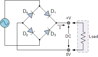
Electronics Tutorial about the Full Wave Rectifier also known as a Bridge Rectifier and Full Wave Bridge Rectifier Theory
Another option, if you want it to be toggled by airflow instead of a microphone, would be to use an airflow sensor instead. The signal out of this should be a lot cleaner and easier to implement dynamic control, since it'll output an analog voltage as you blow air through it. https://wiki.dfrobot.com/F1031V_Mass_Air_Flow_Sensor_SKU_SEN0360
Wiki: F1031V Mass Air Flow Sensor adopts thermodynamic principle to detect flow rate of gas medium in the flow channel, with high precision and good repeatability.
median hemlock
true void
Hey all, I'm making an electronic woodwind. Currently, I've built and tested the...
A differential pressure sensor measuring both sides of a source of resistance in the airflow path (screen or other perforated obstruction) will give you a voltage related to flow. It’s analogous to V=IR in electronics. If all you wanted was a binary “flow” you could pipe the pressure out to an op amp wired as a comparator + set a threshold above which the output will hit the upper supply rail. Pretty close to binary in an analog system.
glacial spruce
If you use #define, it's inserted every place it's referenced, by the C preprocessor. If it's a bulky item, each instance can eat up more flash (and even precious RAM). If you define it as a variable, the different references all point to the same place and share the same memory, and many compilers will put const data in flash (saving even more RAM) and arrange the code to access it from there correctly.
true void
@odd oasis @median hemlock Thanks for the suggestions - I think a pressure sensor may work. I'll give it a try!
 twin bloom
Can a HD audio codec (mainly for PCs that would be running Windows or Linux) be used with Android 11? specifcially with this audio codec: https://temposemi.com/products/pclaptop-hd/stac9200/

STAC9200 (Download Data Sheet) Two Channel HD Audio CODEC The STAC9200 is a basic 2-channel High Definition (HD) Audio CODEC for WinXP (and prior), Embedded and Linux applications. Features Full Duplex Stereo 24-bit ADCs and 24-bit DACs Integrated Headphone Amplifiers Stereo Analog Microphone Support SPDIF Input and
dull basalt
would a cortex m4 be powerful enough to decode flac
median hemlock
A Teensy 3.2 can decode mp3, and FLAC is less complicated of a scheme, so yes. I wish you fruitful google/GitHub searches! Also if you want to add a VS1053 to decode you can use a much less capable processor or sweat the multitasking less.
dull basalt
i think i'm just gonna go with a vs1053 because i also need to run an oled and various other things
frozen parrot
is it feasable to record extremely quiet sounds without exremely expensive microphone setup?
at a reasonable distance
basically, I am interested in recording some pretty quiet stuff from far away, and not sure what is the best way to go about it
there's also the environment's volume concerns
solemn flint
frozen parrot
basically, I am interested in recording some pretty quiet stuff from far away, a...
Is it possible you can use like a reflector dish to "zoom in" on the area and boost the sound level?
frozen parrot
no, not really
azure panther
trying to find a proper audio cable, but I know nothing about audio. The speakers I have seem to have 3 conductors (2 rubber rings). Do these parts mate with that?https://www.digikey.com/en/products/filter/barrel-audio-cables/463?s=N4IgjCBcpgnAHLKoDGUBmBDANgZwKYA0IA9lANogAMIAusQA4AuUIAykwE4CWAdgOYgAvsQC0AJmQg0kLgFcipCiACsdISJCTIlTHIAm3EgAIAVphQBrdUA
Cable Assemblies - Barrel - Audio Cables are in stock at Digikey. Order Now! Cable Assemblies ship same day
I ask because they are mostly "phone jacks" and I don't know if that is significant
please ping me if you have thoughts, I don't check this channel super often
solemn flint
azure panther
trying to find a proper audio cable, but I know nothing about audio. The speaker...
Yes, those would be appropriate for most headphone-style audio cables... 1/8" is fairly standard these days, with 1/4" more vintage-style.
azure panther
1/4" is what I plugged into my bass in HS right?
what I'm hoping to find is a panel mount connector that would allow me to pass audio from my pi, through the walls of my enclosure
solemn flint
I think this would be the right section for panel-mount connectors: https://www.digikey.com/en/products/filter/barrel-audio-connectors/434?s=N4IgjCBcoGwJxVAYygMwIYBsDOBTANCAPZQDaIAzABwUwCsATCIdRQOwwXOU1twzdWfNiAC6hAA4AXKCADKUgE4BLAHYBzEAF9CdNnUQgUkDDgLEyIACwAGGnAPiQ02QpUbthMA6uHjpvEISSHIwfUZHSRlIeSU1TR0QAFomaCMoJQBXc2DyRy0CoA
azure panther
I could probably solder to it if I needed to
just do continuity testing on the cable and the jack to see what's what
glacial spruce
solemn flint
Is it possible you can use like a reflector dish to "zoom in" on the area and bo...
Yes, parabolic microphones are a thing. https://www.bhphotovideo.com/explora/pro-audio/buying-guide/the-ps-and-qs-of-parabolic-microphones

B&H Explora
Read about parabolic microphones, their applications, and how to decide which is best for you.
azure panther
How hard is it to make a theremin? They are all analog right?
glacial spruce
Not too hard: the original ones used vacuum tubes, but transistorized designs are out there too. Paia offers one as a kit.
glacial spruce
The basic concept is two high frequency oscillators, one fixed, one variable, then the signals go to a mixer, and the difference frequency is used as the audio signal. This way, small differences in capacitance have a useful amount of effect, as a small percentage change of the high frequency can make for a large difference of the difference frequency.
glacial spruce
I breadboarded this one a while back, but that project is for a silly "visual theremin" notion I had that draws Lissajous figures on a CRT screen that you can control by waving your hands around.
 glacial spruce
It probably will be, if I can ever get it to work
glacial spruce
Here's a nice page Paia makes available describing how their kit (which they named the "Theremax") works: https://paia.com/theresch/

The Theremax manual goes into much greater detail than the following brief design analysis. Hand and body motions in proximity to the sensing antennas produce frequency changes in a Hartley oscillator operating at approximately 750kHz. The signal from this variable oscillator is mixed with a constant reference frequency in a ring modulator and ...
azure panther
I was just perusing their site
It doesn't seem they sell a kit with everything in it, odd. Maybe I'm not seeing it
glacial spruce
I think they do. The electronics is 9505K. The electronics + front panel and antennæ is 9505KFPA, and the entire thing including the case is 9505KC.
azure panther
Ahhh just a layout I'm not used to. I've been trained to expect a different UI/UX
Or not suited to mobile scrolling perhaps
glacial spruce
It's a pretty old site, but they're good folks
azure panther
They seem nice.
If I qualify for the golden state stimulus check I'll consider it heh
 sharp swan
I'm having a problem with distorted audio, like my Circuit Playground Express with Cricket is overdriving the speaker. I'm using the 4ohm 3 watt speaker that was recommended by adafruit but it's doing the same crackly distorted sound on the built-in speaker too. It was working fine, if only a bit crackly before, but I don't know what has gone wrong. Here is a snippet of my code.
Am I spamming? I thought we could come here to ask questions?
A bot removed my code snippet and i don't know why.
glacial spruce
The bot isn't perfect, and sometimes mistakes code constructions for disallowed things.
sharp swan
Ah ok
glacial spruce
You can use things like gitlab or pastebin to share code
sharp swan
Well, my code was pretty much just from the Adafruit page for audioio, for playing a wav file.
glacial spruce
In my experience, crackly sound often comes from data problems (like interpreting unsigned numbers as signed or 8 bit data as 16 bit)
Ah, you might want to try another wav file: it's kind of a catch-all bucket for a bunch of vaguely related formats, and some wav files depend on features that simple code may not support.
sharp swan
Do you know what would cause the audio to start sounding distorted, when it was ok before?
glacial spruce
Before what? What changed?
sharp swan
I'm not sure. Maybe it's because I have the audio playing the same time a servo motor is moving?
glacial spruce
That is likely to be relevant. Servos create a lot of electrical noise. It might be worth trying powering the servos separately and/or adding filter capacitors to the power wiring.
sharp swan
Yep. I changed it back so that the servo waits until the WAV file is done, and it's not nearly as distorted. That's a shame though, I'd hoped to syncronise the movement and the sound.
Not sure where I could add a cap to the setup 😕 This project is something for tonight, but I may experiment with the caps later
Thanks for the information.
On another note, do you know how I could lower the volume of the speaker ... or are all WAV files just going to play at their recorded level?
The page for audioio on Adafruit has something for adjusting the level of a pure tone, but nothing for WAV files
glacial spruce
Adding a volume control would be tricky, but it's worth trying adding a small series resistor to the speaker to lower the volume. Maybe 10Ω or 100Ω or so, depending on the speaker and the volume you want.
lime yew
sharp swan
Yep. I changed it back so that the servo waits until the WAV file is done, and i...
Have you considered a seperate arduino for each task that can send signals to each other. Or a dedicated media playing hardware
sharp swan
lime yew
Have you considered a seperate arduino for each task that can send signals to ea...
Naw, this is a simple project with a circuit playground and a cricket board. I'm not interested in getting in much deeper at this point.
 stuck hearth
I've been playing around with a MEMs microphone recently, and I'd like to create a band-pass filter to select a desired range of frequency awhile adding some gain to the signal. Would it be better to do the filtration pre- or post- amplification? Filtering before would probably help remove noise before the amplification, right?
glacial spruce
Yes, but you may lose signal to noise ratio.
 last prawn
stuck hearth
I've been playing around with a MEMs microphone recently, and I'd like to create...
last prawn
stuck hearth
I've been playing around with a MEMs microphone recently, and I'd like to create...
This depends on the filters you're using. Linear processes don't matter what order the processing is applied in - but if you're using a filter that changes behavior depending on volume then that can effect what you want to do. If its a transparent filter then it probably doesn't matter. (For the example where it does matter - the answer of which order isn't straight forward - for example - if you like how the filter behaves at a certain volume level, you might want to apply the gain before to hit that level before applying the filter)
filters with saturation/resonance are the type that are more likely to be non-linear
stuck hearth
So if the gain from the op amp clips, it would be at those times when the filter begins to act differently, correct? I think I understand where your coming from with the order of operations won't affect things.
last prawn
Not even clipping necessarily - non-linear audio processors can process differently at different input levels. For example - if a filter has some kind of saturation (not related to clipping) - you might get more or louder harmonics added by the filter the louder the input signal is
stuck hearth
It's almost like a LPF, a HPF, and a gain are all "multiplying" with the input signal, which can happen in any order in linear math.
last prawn
Yeah, and in general - most filters you'll work with are going to be linear enough that it shouldn't matter - you'd probably know if you picked one that isn't. Just look out for weird filter parameters like "saturation" and avoid them for this case
(most filters aren't linear-phase so they'll all have a small effect - most noticeable on transients - but its usually not substantial enough to matter for most uses)
stuck hearth
Ok, thanks for the input! I think a filter involving a BJT of sorts might be non-linear in nature. A BJT has that sort of log-like roll off when saturated, which would probably be introduced in the filter.
Yeah, I'm really just playing with simple RC filters, so they are pretty linear.
last prawn
Here are 2 images - 1 impulse, and then it processed through an IIR high pass filter - you can see the highpass smears the frequencies in time. an FIR filter generally avoids this but has other constraints.


Sorry, those are out of order! the one with the smear in the low end is the processed one
 shrewd sequoia
Hi, does anyone know if right and left volume levels can be controlled individually in bluetooth?
 mystic elm
does anyone know which of the adafruit speakers are compatible with the circuit playground bluefruit? I'm a bit confused by the wattage requirements listed online - I'm trying to get better sound quality than the built in speaker has
random bone
mystic elm
does anyone know which of the adafruit speakers are compatible with the circuit ...
The on-board amplifier is available only to drive the tiny on-board speaker. However, the audio signal is available at the Audio pin. You will need an external amplifier that takes line-level input, and can drive the speaker of your choice.
so for instance https://www.adafruit.com/product/2130 could drive one of smaller speakers or even the 3W speakers. Because the output is PWM, ideally you would add some filtering components to reduce some of the noise caused by using PWM audio
This super small mono amplifier is surprisingly powerful - able to deliver up to 2.5 Watts into 4-8 ohm impedance speakers. Inside the miniature chip is a class D controller, able to run ...
azure panther
Does a cable like this have three conductors?

I need to cut one end and connect the proper lines via soldering to this panel mount connector

My plan was to, pre cutting, plug the line in and use a multimeter to figure out which solder cup is connected to which part of the plug end of the cable, then once I have determined which is which, cut the cable solder the wires and plug the intact end into a pi
solemn flint
azure panther
Does a cable like this have three conductors?
Yes, it would generally have 3.
azure panther
Ok thanks. Thoughts on my plan?
solemn flint
azure panther
Ok thanks. Thoughts on my plan?
Seems reasonable, yep. You can cross-check against the connector datasheet, too.
azure panther
Ok thanks
What's the proper name for each section of the plug? Like the tip, middle part, and bottom?
dusty rivet

How much do you truly know about your headphone jack and its impact on the quality of your audio connection? This is the guide to explain it all.
azure panther
Ahh thanks
Dang I might need to order some real skinny shrink tubing
Any recommendations on tube diameter to isolate these prongs? I don't know anything about the size of the conductors in the cable
 dusty rivet
3/8” might work
dusty rivet
That might work
It’s the bigger one that I’d be worried being too big for 3/16 shrink tube
azure panther
I have 1/4 inch too
azure panther
dang, the datasheet (https://media.digikey.com/pdf/Data Sheets/Switchcraft PDFs/3_5mm_Series.pdf) only shows me what I already knew, that the T pin is the tip. I guess I'll go probing
seems like it would be nice of them to include this dimension. I can measure it but still
 azure panther
let me check, one sec, had to clock in from lunch
azure panther
dusty rivet
How close am I? Lol
not too far off, the unthreaded portion is .33"
threaded portion seems to be about .37
dusty rivet
Not bad
azure panther
I think I'll use a .39" hole
although my ability to be that precise is limited
what does "3 conductor open circuit" mean?
 azure panther
is it a bad idea to bend the Tip and Ring (small and medium sized ones) outward so that I have more room for soldering?
ah I guess if I do that, I can't get the nut and washer off
dang. Should have guess this would be a problem: the cables inside are too thin for my strippers
dull basalt
just curious but what make studio headphones or speakers produce a much better quality sound than even high-end gaming ones ?
like stuff by schenhauser, audio-teknica etc
tangent to that would be can I upgrade something like the crystal to get something better easily ?
glacial spruce
dull basalt
just curious but what make studio headphones or speakers produce a much better q...
Fancy materials and structure, tuned resonance, sometimes stuff like impedance matching networks, etc. I'm not sure what crystal you're referring to here, like a crystal phono cartridge?
dull basalt
well I though speakers used pizeo crystals just like microphones/phones etc
glacial spruce
There are some piezoelectric transducers, but things like gaming headphones don't use those.
There was a kit available at one point to upgrade Radio Shack speakers, it included some paint to make the cone heavier and change its flexibility and some batting to install to change the characteristics of the resonant cavity. You could theoretically use a similar approach with headphones, but you'd have to do a fair amount of engineering to determine what direction to go, how far, and ways to accomplish that for a particular pair of headphones.
 true tiger
what would i have to do if i want to add another rotary encoder to this code? https://pastebin.com/1qj4xWiC
Pastebin
Pastebin.com is the number one paste tool since 2002. Pastebin is a website where you can store text online for a set period of time.
random bone
true tiger
what would i have to do if i want to add another rotary encoder to this code? ht...
define both:
ClickEncoder *encoder1;
ClickEncoder *encoder2;
 safe holly
Are there any good discords for audio coding/deving? I'm planning on working on some projects with the pi pico but I'm having a hard time finding a pi or coding server not full of weird kids
azure panther
Yeah the only pi related one I could find was pretty rough
I don't know about audio
 haughty zenith
PWM output and a capacitor?
if a PIO unit can boss PWM around, once you have the sound it should be easy going? (guessing alot here)
 unreal lantern

Hi all, looking to build a dice tray triggered by vibrations induced by rolls, how should I wire this piezo vibration sensor to the adafuit FX board ? Push button works fine...
glacial spruce
It looks like that board has a little signal conditioning, so connect - to your zero volt rail, + to a power pin, and the S (signal) lead to a GPIO pin.
unreal lantern
Did that, does not work 😔
odd oasis
Do you have the part number or product page for that sensor module?
If not, maybe measure the voltage on S and see if your trigger gets the voltage high enough to be interpreted as logic high
unreal lantern
odd oasis
So the S signal is an analog signal, as I thought. You can get it to potentially trigger directly, but you may need a pretty hard impact to actually get the sensor output high enough to trigger reliably.
unreal lantern
Hmmm I think it might be easier using a "simple" vibration coil switch...
odd oasis
Probably. These modules are intended to go to an arduino or similar mcu for basic signal processing. This method offers a wider range of available thresholds, but may not be ideal for your application.
true tiger
random bone
define both:
```c
ClickEncoder *encoder1;
ClickEncoder *encoder2;
```
wont that mess up such lines? if both encoders have the same values and last values?:
value += encoderA->getValue();
value += encodeB->getValue();
do i have to also define 2 different values and 2 different last values?
random bone
true tiger
do i have to also define 2 different values and 2 different last values?
Yes, you’ll have to make separate everything, since it’s two completely separate instances
valueA etc
true tiger
random bone
Yes, you’ll have to make separate everything, since it’s two completely separate...
ok i tried doing this before but it didn't work. maybe i forgot some things
 distant urchin
Do any of you know how I can run a .exe file on my mac? I have winebottler but I can't find EncodeAudio.exe on it and need it for a project. I'm trying to basically do this on my mac: https://www.youtube.com/watch?v=5i9OShmX2NI&t=122s

Please Like , Share and Subscribe👍👍✌
Code and Circuit Diagram :
http://thescrewdriver.c1.biz/Arduino-Talking.html
———————————————————————
Components Required :-
Arduino Uno :
https://amzn.to/36DdqK7
Speaker :
https://amzn.to/37M5Du5
TIP 122 Transistor :
https://amzn.to/3dgDlZN
Breadboard :
https://amzn.to/2XCh2rZ
Jumper Cables :
http...
glacial spruce
I'm /guessing you mean you can't find the file on the Wine volume. I think you can either set up a transfer path (Sep or somesuch) or a shared folder
muted wind
anyone have a recommendation where i can find just the board of a usb speaker that will work with a pi? basically the smallest possible board that works like this:
https://www.adafruit.com/product/3369

Add some crisp and compact audio to your project with this Mini External USB 2.0 Speaker. It's USB-only and does not require or use a 3.5mm audio jack. You'll get great audio, ...
glacial spruce
It may be easier to just use the Pi audio output
muted wind
that's not an option for pi zero
 hard elbow
I wonder if anyone can assist. I have the Adafruit Audio FX mini and the sound was really not loud, so reading more, I bought the mono amp PAM8032A and another speaker 4Ohm/3W I connected them all on the breadboard and using a powerbank to power them but I cant get sound out of the speaker with the mono amp installed. There is a ticking from the speaker. Without the mono amp everything works, just on very low volume. Any ideas what else I can try?
 random bone
hard elbow
I wonder if anyone can assist. I have the Adafruit Audio FX mini and the sound w...
random bone
hard elbow
I wonder if anyone can assist. I have the Adafruit Audio FX mini and the sound w...
It's a little hard to tell: the SD pin is not connected, is that right? It is an active-low signal. Did you try adjusting the tiny potentiometer on the board?
A powerpack can be flaky because it requires a minimum current to turn on. What happens if you power this from an AC adapter or USB port?
A+ and A- are going to R and gnd, correct?
and Vin is going to "BUS"?
hard elbow
the tutorials I looked didnt have that connected either. So I left that, I will have to read up on the potentiometer. I hear a clicking noise from the speakers.
Yes A+ to R and A- to GND
and yes GND to GND and VIN to BUS
random bone
you could try feeding A+ A- from something like a headphone jack on something that produces sound, to check whether the amp is working. Use some batteries or a 5V supply
in other words, divide and conquer to isolate the fault
hard elbow
Just put it on with a AC adaptor and same result. Yeah I have been going through without amp, it works, without the button, no difference, different speaker, same result.
Been trying to check what it is before I pull the trigger and get the Audio FX sound board with 2+2W amp on board
hard elbow
OK, reading up on the pot and digging out my volt meter
random bone
I used this amp myself from an analog out pin on a board recently and didn't have trouble
hard elbow
Yeah, so far everything I followed worked, that is why I am surprised. It is my first try at this stuff, but I worked on gameboy/nintendo DS stuff before.. it is all a learning curve, fun tho
hard elbow
random bone
you could try feeding A+ A- from something like a headphone jack on something th...
Can you explain how I would do that. Sorry English is not my native language and I am not sure how I would connect a headphone jack
random bone
do you have alligator clip leads?
do you have a 3.5mm cable with two plugs? Plug one end into a phone or something else that has a headphone jack, and then you will connect some terminals on the other end to the A+ and A-
But did you try turning the control on the amplifier already? You need a small screwdriver, like a jeweler's screwdriver.
hard elbow
random bone
But did you try turning the control on the amplifier already? You need a small s...
I found something that says vol on the AMP. I have tiny screwdrivers.
No alligator clips, or anything like that.
random bone
the vol is the easiest to try for now
hard elbow
Yeah turned the little dial, but no difference either way.
The speaker makes an odd clicking sound when connected, I may get the audio FX with the 2+2W amp included and another mono amp (as they are cheap) and see if it is the amp
random bone
hard elbow
Yeah turned the little dial, but no difference either way.
if you are making an order consider getting some mini alligator leads and maybe also alligator to breadboard pins, e.g. various of these: https://www.adafruit.com/?q=alligator&sort=BestMatch
they are all handy
hard elbow
I've added some. Was trying to find the 3.5mm jack with crocodile clips but neither store that sells this stuff had them
distant urchin
Hey does anyone know if arduino can run audio files of a voice with just a cheap speaker and regular breadboard stuff? Thanks!
lucid anchor
distant urchin
Hey does anyone know if arduino can run audio files of a voice with just a cheap...
I don't see why not, as long as the filetype is compatible with what Arduino can handle, and your board is beefy enough to handle the Arduino audio stuff. But I'm not super great with Arduino, so I'm kind of guessing here. Cheap speaker will sound not great, but no reason you couldn't wire it up on a breadboard with an amp and the microcontroller.
random bone
distant urchin
Hey does anyone know if arduino can run audio files of a voice with just a cheap...
There is not enough flash on the Arduino to play audio of any length. You'll need an SD card shield or similar
 heady musk
@distant urchin you can try some mp3 modules such as DFPlayer
I would so some research if I was you, searching "mp3 module" in google
is a good place to start
there are many options
lucid anchor
random bone
There is not enough flash on the Arduino to play audio of any length. You'll nee...
Good call, thanks Dan. I think that's what I was getting at with "beefy enough" but I didn't realise how strict that limitation was. Now I know.
 golden flower
I attend church where they catter to the hard of hearing and deaf community. Is there a way to connect a Pi or something to the sound board so the service can be broadcast to those who want on their phones? im guessing less then 100 connections
solemn flint
Yes, I think there are audio HATs for the Pi which would have audio inputs.
Or you could use a USB audio device.
odd oasis
There are many ways to go about this, but a Raspberry Pi should be plenty capable of handling a webserver for a live broadcast service of some sort. Audio input to the Pi shouldn't be too difficult, the bulk of the labor would likely be designing the web/mobile app for said purpose.
golden flower
@odd oasis I agree, trying to figure out hardware needs
odd oasis
Well, for audio input, the usual solutions involve a USB or I2S sound card. I2S usually comes in a HAT form that mounts on your 2x20 GPIO connector, or you can pick up a USB input device and follow https://learn.adafruit.com/usb-audio-cards-with-a-raspberry-pi.
What kind of interfaces does your sound board have?
golden flower
just xlr or headphone its an antique
odd oasis
Hrm, audio input on Pi HATs isn't common, especially ones supporting line in. I think https://thepihut.com/collections/raspberry-pi-audio-hats/products/hifiberry-dac-adc and its pro version are the only off-the-shelf solutions as far as stacking HAT boards are concerned, so it might be worth looking at some USB options for comparison.
heady musk
Dr. Taylor fm transmitter maybe ?
just plug your phone's headset and tune to the frequency
there are also multi-stream BT transmitter
golden flower
@heady musk I have not been able to find multi-stream BT
heady musk
ah let me see i have seen such device a while back
golden flower
that would be great, wish adafruit had one
heady musk
i think was this
tr2403
there is this chip
SC14WAMDECT
for tour guide systems
but this means additional hardware
on the receiving end
golden flower
thanks the tr2403 is radio, not bt
odd oasis
Bluetooth Audio broadcasting isn’t available yet, to my knowledge. It’s being developed as part of BLE audio, whenever that becomes a thing.
Multi pairing isn’t exactly a feasible solution here, either, considering the scale this application scopes.
Radio, on the other hand, is very doable and not hard to implement. Most phones actually are able to access fm radio, though its setup isn’t always trivial.
As far as modern conveniences go, a web server or an audio streaming service might be the easiest way for people to access from their phones.
distant urchin
heady musk
<@!418443628361547796> you can try some mp3 modules such as DFPlayer
alright i'll try that thank you!
distant urchin
random bone
There is not enough flash on the Arduino to play audio of any length. You'll nee...
okay ill take that into account, thank you!
distant urchin
lucid anchor
I don't see why not, as long as the filetype is compatible with what Arduino can...
thank you!
 tough path
does this seem like a remotely reasonable way to do a mixer?
 glacial spruce
That's more like a balance fader than a mixer (mixers generally direct signals to a virtual ground summing node). Note that you only have a 5V unipolar supply, which limits the range and polarity of the signals it can handle. I'm not sure the LED circuit (level meter?) will do what you want.
tough path
I'm not sure about the LED circuit either lol
how would I power something like this from a normal DC power supply?
I guess the issue is that as audio signals they can go < 0V right?
azure panther
Where would folks go if they wanted a 1/4 inch audio cable intended to be cut at one end and the signals tied to dupont jumpers? I need to test audio playback from a samd51
glacial spruce
Right. There are a few approaches. There are "rail splitter" chips that simply derive an intermediate voltage, which you can then use as a ground reference (but only if your USB ground and your audio ground aren't the same ground). The usual approach is to AC couple the signals and then bias them midway between 0V and 5V.
azure panther
I've cut exactly one cable in my life and one of the signals was unshielded which is not desirable
azure panther
Hmmm thanks I'll check that out
glacial spruce
Or just buy a 1/4 plug and attach your own wires to it.
azure panther
That was my other plan, small alligator clips if I can find them
tough path
would I need to remove the dc bias on the output or does that not matter?
is this a good way to add a dc bias?
 glacial spruce
That's one way, you can also use an op amp if you want lower impedance bias.
As for the output, it depends on what you're driving.
tough path
I already have op amps on the inputs as buffers, is there some way to drive the bias that way?
glacial spruce
Yes, adding an op-amp as a buffer after your resistive divider is a popular approach for a low impedance bias supply.
azure panther
Would audio played over a DAC with CP necessarily be mono? I know nothing about audio and only internalized my fathers insistence that stereo is always what you want.
But he wasn't an audio engineer
On an MCU like the SAMD51
glacial spruce
I think you can play stereo samples
azure panther
Samples? I'm hoping to play something from an SD card over a 3.5mm jack
lethal slate
You would set up audioio.AudioOut with two DAC pins, left and right. https://circuitpython.readthedocs.io/en/latest/shared-bindings/audioio/index.html
azure panther
Ahhhhh
Cool
That's very neat.
I'll talk to our audio engineer and see what he prefers
Thanks
lethal slate
No problem.
azure panther
trying to sell my boss on a SAMD51 build. Just want to make sure that anyone here doesn't think I'll have too much trouble reading an MP3 from an SD card and (relevant to this channel) playing either mono or stereo audio over an audio jack?
plz ping me with thoughts, I'm running around today
odd oasis
azure panther
trying to sell my boss on a SAMD51 build. Just want to make sure that anyone her...
Not at all, https://learn.adafruit.com/circuitpython-essentials/circuitpython-mp3-audio makes it look easy enough.
 azure panther
nice that's what I thought, just wanted to sound out the idea and see if it was far fetched. Appreciate the reply.
I'm frankly tired of dealing with the pi for the simple task I'm doing.
 neon harbor
Hi
I am using circuitplayground bluefruit and crickit with a mini oval speaker from adafruit and my sound is very noisy. I am wondering if this just is the quality I get out of something is wrong in my setup. I converted the file in Audacity and normalized it, could the volume be too high?
lethal slate
Are you playing .wav or .mp3? How does the file sound on your computer?
neon harbor
I am playing a wav and it sounds good on my computer
lethal slate
You can use the audiomixer module to change the playback level.
azure panther
Re: audio quality, Just doing more research before I commit to using a SAMD51, anyone who has used it for MP3 playback: how does playback quality compare to something like using a pi with pygame?
random bone
azure panther
Re: audio quality, Just doing more research before I commit to using a SAMD51, a...
there is a limit to the bit rate you can use: I don't remember what it is. Are you using a Pi with the crude PWM audio out? The SAMD51 has a DAC and can do analog audio, or you can do I2S audio out and use an I2S-capable amplifier
azure panther
interesting OK. I haven't gotten a SAMD51 set up yet to test. On the pi I'm using just the 3.5mm audio jack which I assume has some kind of IC in between the CPU and the jack but I don't know.
I'm planning on using CP but I can use arduino if I have to. Would an I2S method have "better" quality than just using two DAC channels and ground to make stereo audio?
quality is the most important thing to me, so I can keep using a pi if I must, but would prefer a simpler system. I've noticed the occasional skipping in the pi, which I presume is because the OS was busy with some other task
This for example seems perfect for my needs.

Adafruit Learning System
A nice and fully-featured I2S stereo DAC for you!
Assuming (I think it's safe to assume) that I can also use I2C at the same time.
solemn flint
Yes, there should generally be no conflict between I2S and I2C.
The I2S connections generally double up with the SPI peripheral.
azure panther
Ahh ok. Does doubles up mean I lose SPI?
solemn flint
Depends on the chip. Usually they will have more than one SPI peripheral available.
azure panther
Let me check out the SAMD51 then
looks like SAMD51 only has one spi bus?
But fortunately the only other IC I think I need is I2C. Let me move to #help-with-hw-design
glacial spruce
azure panther
looks like SAMD51 only has one spi bus?
I think there's only one QSPI bus, but some variants can have up to 8 hardware SPI ports
glacial spruce
azure panther
Where would folks go if they wanted a 1/4 inch audio cable intended to be cut at...
Not what you're looking for, but I thought of your question when I saw this https://www.sweetwater.com/store/detail/LINE2USB--behringer-line2usb-audio-interface

Sweetwater
2-channel USB Audio Interface for Line-level Devices with 1/4" Outputs
 subtle gulch
Would you recommend an electret mic or MEMS PDM mic for building an audio reactive light?
azure panther
glacial spruce
Not what you're looking for, but I thought of your question when I saw this http...
That's neat!
subtle gulch
Also - is there a board that takes in a line-level audio input to the feather?
random bone
subtle gulch
Also - is there a board that takes in a line-level audio input to the feather?
do you mean feeding the audio to a Feather pin connected to the DAC?
random bone
subtle gulch
Would you recommend an electret mic or MEMS PDM mic for building an audio reacti...
we have audiobusio.PDMIn for taking short audio samples. We don't have any equivalent for analog signals (sampling multiple times and dumping in a buffer)
The CPX and CPB uses PDM mic and have several audio-reactive projects/examples avaialable
subtle gulch
random bone
The CPX and CPB uses PDM mic and have several audio-reactive projects/examples ...
I want to send audio via a TRS / 3.5mm cable rather than depending on a microphone. I found this breakout board that seems like it will do the trick: https://www.dfrobot.com/product-514.html
This Audio Analyzer module can be used to create sound visualizers, detect patterns in music or add sound activation to your microcontroller.
glacial spruce
That may be overkill for what you want to do. You can make an attenuator to adapt a line level signal to safely drive an audio pin.
random bone
subtle gulch
I want to send audio via a TRS / 3.5mm cable rather than depending on a micropho...
As long as the line-level does not exceed 3.3v, you can send it directly to a pin and use AnalogIn. But that takes discrete samples, and is not good for taking many samples at high speed. If the level exceeds 3.3V, you can attenuate it as madbodger suggests, with, say, a voltage divider (two resistors)
 grand lance
https://www.adafruit.com/product/1743 https://www.adafruit.com/product/987 https://www.adafruit.com/product/5299 https://www.adafruit.com/product/4886 these are the 4 main components i have on hand. im trying to make an mp3 player with a touch screen. having a little trouble with it but for now, do i need any other boards? not parts, boards
random bone
grand lance
https://www.adafruit.com/product/1743 https://www.adafruit.com/product/987 https...
The RP2040 does not have a DAC, so you can't do normal analog audio out. You can do PWM audio out, but that will limit the quality. You can do I2S digital audio out, and use an I2S amplifier, like https://www.adafruit.com/product/3006 (note it's mono). Or you can use a SAMD51 board. SAMD51 does have a DAC. Something like a PyPortal has a touch screen on it.
https://learn.adafruit.com/pygamer-mp3-player-with-circuitpython is a working project (not touch screen)
grand lance
random bone
The RP2040 does not have a DAC, so you can't do normal analog audio out. You can...
im using a MAX98306 (adafruit part 987)
its sterio
random bone
that is an analog-in amp, not I2S
There are also these VS1053 solutions, which offload the MP3 playing to another chip (and the MP3 storage to another chip as well): https://www.adafruit.com/?q=vs1053&sort=BestMatch
grand lance
so if i add say this: https://www.adafruit.com/product/1381, i should have everything i need ? use the audio amp bpard to connect cpeakers
random bone
It depends on your use case. If you are willing to use update the SD card yourself, that would work. I'd suggest looking at VS1053 topics in the forums to look for any possible issues: https://forums.adafruit.com/search.php?keywords=vs1053. There is some discussion of SD cards that work or not, for instance.
(depends on SD card size)
grand lance
do i need the feather for it at all?, or does it work as a bridge between the codec board and the touch screen?
random bone
yes, the latter, the feather would serve as a controller
let me look a little more closely, hold on
random bone
grand lance
do i need the feather for it at all?, or does it work as a bridge between the co...
We don't have a CircuitPython library that controls MP3 playing on the VS1053. Were you wanting to use CPy or Arduino?
grand lance
there is a library for it. i looked for it.
random bone
there is a library, but it does other things
I picked the mono amplifier, but here is an I2S decoder that will hook to your current amplifier: https://www.adafruit.com/product/3678
https://learn.adafruit.com/mp3-playback-rp2040 Have you seen this guide?
so the 3678 can send line-level output to your current amp
grand lance
i did not see that
random bone
I would forget hte VS1053 for now; sorry I brought it up
grand lance
so hook up to the feather like i would the rasberry and modify for a sterio?
random bone
send I2S audio from the Feather to the 3678. So you would use audiobusio, as described in the guide
when you say "raspberry", which do you mean?
grand lance
random bone
Any board with an RP2040, like the Feather RP2040 you ahve
grand lance
ok, so get the 3678 wire my amp to it, then wire the 3678 to my feather?
random bone
exactly
3678 does digital to analog conversion, but isn't strong enough to drive speakers
random bone
you could use two 3006's, but also can do this
random bone
grand lance
just in sterio
yes
grand lance
then wire in the screen and program code. will i need the gpio expander
random bone
I don't think so, unless you want a lot of buttons. You can use the display in 8-bit mode or in SPI mode
You'
you'll need to do a pin inventory to make sure you have enough pins.
grand lance
not according to the tutorial. it seems they only have a guide for spi
random bone
You might want to start by getting just MP3 playing working, without the touch screen. Verify that works. You can use PWMAudioOut for now and switch to I2S later, when you get the 3678. Try some simple touch-screen stuff now with the current display on a breadboard, to make sure you can get it to work. Then put the two things together. It will be less frustrating if you can debug one major aspect at a time
grand lance
still trying to get the touch screen to work other than just backlight
subtle gulch
random bone
As long as the line-level does not exceed 3.3v, you can send it directly to a pi...
Got it. Trying to keep things simpler by using off the shelf components rather than dealing with building / debugging custom stuff. I'm more of a software guy, so leveraging Feather / STEMMA to avoid more than basic header and wire soldering 🙂
I'll try this approach if the audio analyzer module doesn't work well
 versed torrent
I'd like to play some audio out the DAC on a SAMD21 (on a Circuit Playground Express) - Anyone have any pointers to good sample code. Key is I want to do it in Audrio C++, not Python.
I'd like to do the audio out via DMA as well
random bone
versed torrent
I'd like to play some audio out the DAC on a SAMD21 (on a Circuit Playground Exp...
The Arduino Zero is a SAMD21 board, so use that as a websearch term, e.g.: https://www.arduino.cc/en/Tutorial/SimpleAudioPlayerZero
versed torrent
excellent - the source to that AudioZero library should show me how to do it!
random bone
I think there are number of other examples
azure panther
I would like to play an MP3 from an SD card using a SAMD51 and this product https://www.adafruit.com/product/3678. I see this video https://www.youtube.com/watch?v=4xh_mPaYG3s using an NRF chip and that a SAMD51 is mentioned as being next up for testing. Does anyone know
- Which PR it was so I can check it out
- If the SAMD51 is capable of high quality MP3 playback with the DAC breakout above?
- If not 2, is there a chip I should look for to make this possible?
I would prefer to use circuitpython but I don't mind arduino if needed
lethal slate
I've tried playing mp3 files with circuitpython on several boards. I find it more suited to playing sound effects than music.
azure panther
ah ok
I was trying to move away from using Pis because what I'm doing besides playing music is very simple and I'm tired of the added complexity. Looks like I'll need to keep using the pi though
thx
lethal slate
I don't know but arduino might work for you.
azure panther
That's what I'm going to try next, on my own time
random bone
azure panther
I would like to play an MP3 from an SD card using a SAMD51 and this product <htt...
You could try this https://learn.adafruit.com/mp3-playback-rp2040 and adapt it to SAMD51.
weary gyro
Yes, if you're doing the decoding in software (as opposed to using a hardware decoder like a VS1053 board), and you want to use CircuitPython, the audiomp3 library that's available on SAMD51 boards uses the Adafruit_MP3 C library (https://github.com/adafruit/Adafruit_MP3) and that looks like it supports stereo 44.1 kHz CBR MP3s. That's high quality but I can't tell if it also supports VBR (variable bit rate) encoding, which I think is more common. That means you may need to run all your MP3s through Audacity to re-encode them. If you're okay with Arduino and an outboard MP3 decoder, I've used a few VS1053-based MP3 decoder boards and they work well. The Arduino sketch then is mostly just doing the shuttling of data from SD card to MP3 decoder chip. The nice thing about the hardware MP3 decoders is they support many formats: MP3 (VBR CBR) / WAV / FLAC / Ogg
GitHub
mp3 decoding on arduino. Contribute to adafruit/Adafruit_MP3 development by creating an account on GitHub.
grand lance
for volume control, a tutorial says to use a 50k pot. do i really need it, or can i get away with a 10k or a 100k?
random bone
grand lance
for volume control, a tutorial says to use a 50k pot. do i really need it, or ca...
100k would certainly do it. 10k might possibly not get quiet enough. It depends on how it's wired
 deep valley
I have a headset with a mic with a combo jack. The jack has broke and I wanted to take this opportunity to make this headset a USB or Bluetooth one. are there any pcbs meant to retrofit this headset to be bluetooth or usb compatible?
odd oasis
deep valley
I have a headset with a mic with a combo jack. The jack has broke and I wanted t...
Bluetooth is a bit difficult, since you have to add a battery for wireless functionality. I don't know of any PCBs for headphone modding, but you could use something like https://www.amazon.com/DuKabel-ProSeries-Mic-Supported-Headphone-External/dp/B07RS11M1T to accomplish the same effect. Just splice the wires properly and it SHOULD work.

USB external sound card can easily add a 3.5mm aux integrated TRRS port to your computer, which enables you to connect your existing headsets or microphones with 3.5mm 4 pole TRRS plug to your PC through a USB interface. Note: It does not work with headset with separated headphone and microphone ...
haughty zenith
I'd like to code one of my circuit playgrounds to detect the sound of my forced air heater for logging purposes, but I've not seen too much on using the mic.
random bone
haughty zenith
I'd like to code one of my circuit playgrounds to detect the sound of my forced ...
haughty zenith
the way people have talked, I'm surprised to see the ability to read PCM from the mic
random bone
you can read short bursts of audio, but there isn't enough RAM to record a long amount.
haughty zenith
presumably this is plenty to discriminate between refridgerator hum and forced air hum though
also just the volume detection should be able to emulate that auto IR volume control gadget I saw someone else build, awesome!
 river ermine
random bone
This might help: <https://learn.adafruit.com/adafruit-circuit-playground-express...
river ermine
random bone
This might help: <https://learn.adafruit.com/adafruit-circuit-playground-express...
When I try running this code on my circuit playground express it causes the whole mu editor to freeze and disconnects my device and I have to flash erase the board and reinstall circuitpython before it is functional again
I added some print lines to see where the code stops working, and it breaks right at the mic.record(samples, len(samples)) line, not sure what the issue is and if it's occurring only on my board.

Does it require any specific circuitpython libraries to be moved into the lib folder on the playground express? I am running version adafruit-circuitpython-circuitplayground_express-en_US-7.0.0
haughty zenith
I expect a relevant error to be printed in that case
river ermine
The whole editor stops responding after printing the “test4” line so unfortunately I cannot see the error that is actually occurring in the console
random bone
river ermine
When I try running this code on my circuit playground express it causes the whol...
Could you please upload the code as a file, so I can see the whole thing? Use the "+" on the left. Try the latest 7.1.0-rc.0 as well, from circuitpython.org.
river ermine
random bone
Could you please upload the code as a file, so I can see the whole thing? Use th...
Thank you! trying the latest adafruit-circuitpython-circuitplayground_express-en_US-7.1.0-rc.0 worked
random bone
I don't remember what we fixed, but glad it works!
 hearty patio
Hello, I need some help with the Music Maker FeatherWing (https://www.adafruit.com/product/3436). I've installed the Arduino lib Adafruit_VS1053 and when I run File -> Examples -> Adafruit VS1053 Library -> feather_player on the ESP32 (https://www.adafruit.com/product/3405) it won't play an mp3, but when I run this code on the nrf52840 sense, it will play. Can anyone test this code and let me know if works for them on an ESP32? Is there anything I need to change? I would like to run this on the ESP32 as I would like to create a webserver rest api to interact with the audio player.

Aww yeah, it's the Feather you have been waiting for! The HUZZAH32 is our ESP32-based Feather, made with the official WROOM32 module. We packed everything you love about Feathers: built ...
I should also mention that when the call to printDirectory happens on the esp32, it does not print out track001.mp3 and track002.mp3, but it will print these out using the nrf52840.
celest cedar
hearty patio
Hello, I need some help with the Music Maker FeatherWing (https://www.adafruit.c...
Just a guess...Did you see this note? have you tried using a Pull-up on the TX pin? https://learn.adafruit.com/adafruit-music-maker-featherwing/troubleshooting. Not likely the issue, but worth a try.
hearty patio
celest cedar
Just a guess...Did you see this note? have you tried using a Pull-up on the TX...
I added pinMode(17, INPUT_PULLUP); and it had no effect.
celest cedar
sorry...
hearty patio
I appreciate the help though
celest cedar
I'll see if I can find the parts to try it...hunting.
celest cedar
hearty patio
Hello, I need some help with the Music Maker FeatherWing (https://www.adafruit.c...
I just tried it with a Feather Huzzah32 and a Music maker featherwing and it runs but does not play the .mp3 files on my SDCard. It does list them -- I just get a beep.
I'll try another MCU
hearty patio
Thanks for confirming. I am able to get the beep, can't list the files, and can't play the mp3s.
celest cedar
I get the same results with a feather m0 express. I'm not sure my SDCard is properly configured.
hearty patio
Thanks. I was able to get it to work with the nrf52840 so I might just add an airlift featherwing to it
I'll see if I can somehow get all that to work together
celest cedar
I'll try an nrf52840 -- back to hunting
celest cedar
I get teh same results on a feater nrf52840 bluefruit sensse so it may well be my SDCard.
celest cedar
hearty patio
just wish the esp32 would work on it's own
Ah -- I did not reame the files to TRACK001.mp3 and TRACK002.mp3 -- the esp32 works fine!
hearty patio
SD card needs to be formatted to fat32.
celest cedar
yes and file name TRACK001.mp3 etc
hearty patio
Oh, you did all uppercase? I did all lowercase and renamed in the code to all lowercase. I'll try all uppercase
celest cedar
I don't think case matters...
lower case works ok for me as well
but I did not modify the code from the example
I have to go offline -- I'm not sure what to suggest other than try the unmodified example -- maybe a different card.... good luck!
hearty patio
Ok, thanks for the help. I'll try in a bit
hearty patio
celest cedar
I have to go offline -- I'm not sure what to suggest other than try the unmodifi...
what size is your card?
celest cedar
256Mbyte
celest cedar
hearty patio
what size is your card?
also just tried with a 16GByte Sandisk card - worked OK
hearty patio
yeah, switched to an 8 gb card and the esp is listing out the contents of the card now, but not playing the mp3
I wonder if there is a certain bit rate for the mp3 file
celest cedar
not sure -- mine came from various souces.
hearty patio
ok, so now I got it so it can list the contents of the sd card. it starts playing the file with a bunch of weird pauses, but then quits out and stops playing the track.
celest cedar
Progress!
celest cedar
I have no idea why it is not working for you. Do you have any other than the music maker connected.
hearty patio
celest cedar
I have no idea why it is not working for you. Do you have any other than the mus...
I don't. I've looked at the solder and all the pin's look good
celest cedar
hearty patio
I don't. I've looked at the solder and all the pin's look good
strange -- today I am having problems accessing the SDCard via the ESP32 -- usually not fount at all, but sometime it does but then cannot play the files properly. It works fine with a feather m0 express. Also: except for the SDCard issues, the ESP32 is working fine with the music maker and WiFI -- I can stream music (mp3) from a URL just fine... the SDCard is very puzzling...
celest cedar
@hearty patio FYI -- I've been doing more testing and I hooked up an external SD Card to the ESP32 -- what I am finding that it work OK when the musicmaker is not connected, but not with it connected. Something is conflicting...not sure what yet.
hearty patio
wow! thanks for looking into that. I'm taking a different path. got a sense, hooked up to an airlift with a music maker featherwing on top. trying to get that to work
so one thing, I formatted the sd card as fat32 with a block size of 4096
thats when the sd card started working/reading
celest cedar
This has been a good exercise. I now have my esp32 streaming my favorite celtic music channel...I'll try to understand the SDCard issues more, but will move back to some other projects for awhile. Good luck with your projects!
celest cedar
hearty patio
thats when the sd card started working/reading
good to know- thanks.
celest cedar
let me see if I can find the original link
hearty patio
was it esp32 radio or 205 internet radio?
celest cedar
here is the sketch
it uses an on/off switch and a pot for volume control -- they can be removed.
celest cedar
You're welcome. Have fun!
I don't recall where it originally came from to give proper credit. It was not original..
ah - here is the source for the original guide.https://learn.adafruit.com/adabox004/internet-radio
hearty patio
cool
grand lance
so, how much space should be sufficient for 6-13 4-5 minute songs? im making my own storge devices
celest cedar
there are many options and i know very little about them but I think you'll need to provide more information to get good advice. What format are you using?-- for example, I have 2 songs in MP3 format about 4 minutes each -- one is 5Mbytes - the other is 9.MBytes...
grand lance
i dont know. im just needing a general number that should be sufficient enough in most cases
celest cedar
Hopefully someone more knowledgeable can comment.
solemn flint
A high-quality MP3 has a bit rate of 320kbps, so 13 5-minute songs would be about 1.2Gbit, or about 150MB on the upper end. If you compromise on the quantity or quality, you can shrink that, but generally you'd probably want to be aiming for somewhere in the 32-256MB storage range... small for SD Cards, mid-range for serial flash chips.
grand lance
ok, so a minimum 200mb should be sufficent for the most part
dusty rivet
Probably
grand lance
so i need 7 32 mbserial flash chips
next step, learning how to string them together and making a board
solemn flint
You should be able to find single chips in larger capacities. Digi-Key has up to 4Gbit in stock.
grand lance
i generally dont like digikey. mostly because i like descriptions that explain what im looking at and it doesnt have that on the main results page. like their filtering system though
solemn flint
Substitute any distributor, then. "Bigger chips do exist", basically. 😉
grand lance
since i dont know all the terminology that also makes it difficult. like flash-nand, flash-nor
no idea what that means
what are some typical suppliers? all im getting from digikey is surface mount and im hoping for through hole
solemn flint
That's going to be rather hard to find, I expect... through-hole chips are the exception these days.
grand lance
i see. so clock frequency determins?
solemn flint
I don't follow. It's just that all mass-produced electronics use surface-mount, so that's what the chip-makers go for with anything modern. Through-hole parts are generally legacy holdovers.
grand lance
i moved on. i dont know what clock frequency is
solemn flint
For a serial flash chip? It's how fast the SPI bus runs, so it'll determine the read data rate.
grand lance
kk
solemn flint
(Maximum. Often you'll run it slower since the MCU won't be able to go at the full speed anyway.)
grand lance
and here is another issue: minimum quantity. they want me to buy 53 minimum
dull basalt
SD cards for the win, I would guess.
grand lance
for now probably, at least till i have an extra 300 just lying around
the only ones in my range with really low minimums are out of stock
dull basalt
tom's hardware or maybe I don't know ars technica may have a survey article describing all the tradeoffs for mass storage devices in a microcontroller environment (Arduino &c.)
grand lance
i can probably test with the sd to make sure the over all mp3 player workd then build my custom memory later
lethal slate
https://www.adafruit.com/product/4899 512MB XTSD
grand lance
lethal slate
<https://www.adafruit.com/product/4899> 512MB XTSD
Thats perfect. A little large on the storage, but id rather have too much than too little
I could probably desolder the main chip and replace with a larger one if i need to couldnt i
grand lance
lethal slate
<https://www.adafruit.com/product/4899> 512MB XTSD
so i just wire this up onto my custom connector and snap it into an enclosure and bam! its done? use it like a custom sd card?
random bone
it is basically just a non-removable SD card.
lethal slate
Yeah.
grand lance
lethal slate
Yeah.
well thank you. ill have to make a custom connector board, but at lease the storage is solved
last prawn
Has anyone tried to get Munt or parts of Munt compiled to run on an M4? (The full mt-32 emulation is probably too much but a few voices mono-timbral should be ok)
versed torrent
@last prawn that sounds like a fun project. For a software based synth, usually being multi-timbral isn't much of a CPU drain - since changing parameter blocks between voices isn't usually more than passing a different pointer.... though I haven't looked at Munt code
one thing to keep in mind: You'll want to avoid double - as the M4 fpu only does float in hardware. I don't see any in the code except some constants... but I haven't done a full check.
Another thing is: There is a lot of code there, wondering if there are things you could leave out wholesale -
last prawn
The entire think looks like it supports integer arithmetic. The full emulation (which is something like 32 or 64 voice multi-timbral/polyphonic) needs something around a pentium 800mhz which feels out of reach of an M4. I've already gotten a few blocks compiling and running.
Based on experience - the expensive things are probably the resampling and maybe the post-DAC analog emulation which will be easy enough to turn off
versed torrent
ram usage might also be an issue… i bet you can leave out the reverb
you could also fashion 8 voices monotimbral per M4, interconnect a few… and put all the MIDI code on a controller M4…
last prawn
Looks like a lot of the internals are also running sample by sample so theres a bit of room to optimize things for the M4. I'm mostly interested in the virtual analog stuff since I really like Rolands pre-VA synth part generation
My system is software-modular so I really just want a few of the parts but thought I would check to see if anyone already ported or fixed up the code
versed torrent
fun project… keep us updated on your progress!
last prawn
Definitely! I added the i2s DAC adafruit sells to a neotrellis 8x8 (and 3 i2c encoders + a 128x32 OLED). Right now I have parameters/sound/display working with some proof of concept code. Gotta add the neotrellis in and see what the overhead of a simple sequencer is
versed torrent
my current project is simpler: M0 based… touch pads that trigger samples… using accelerometers to have pitch and yaw control filer cutoff and sample position
whole thing fits in a small wooden box… a handheld electronic percussion instrument
last prawn
that sounds sweet! so its meant to be held in 1 hand and played with the other? Sort of like a digital version of those drums?
versed torrent
you hold it in both, like cupping a bowl, and you index fingers tap the copper strips on either side
last prawn
nice. can't wait to see it!
versed torrent
currently struggling with the touch code… the FreeTouch library works…. but it stalls DMA to the DAC about 8 samples every reading
last prawn
oof
Yeah - 3rd party libraries + audio can be tricky.
I have a backup plan of trying to move to an rp2040 just to get 2 threads if there isn't enough time to process the Sequenceer and Parameter changes and get the audio buffer filled in time
versed torrent
The touch issue is that the SAM D21/51 touch controller hardware is the only module not documented. They expect you to use their QTouch library - not open source, huge, and only designed to work in their own IDE... oy! Adafruit and some other person reverse engineered enough to get it work (in FreeTouch) -- but I discovered there is a read from a Read Synchronized register... without the code doing the read sync dance... and this causes the peripheral bridge to stall (which is why even DMA is stalled) - Problem is no one has reverse engineered where the read request register is yet!
I do see float in the MUNT code -- like Partial.h has produceOutput with floats... but perhaps you don't need that version... ---
last prawn
I got it working with the int version - most of the code uses ints and has conversion to floats but the original hardware was all ints so the int versions are more accurate (I'm guessing the SRC and maybe the Analog emulation are the reason they need float support)
I don't have the mt-32 rom (and its illegal to download it). I do have an MT-32 and I've ripped the rom from my D-50 - I just don't know if I'll end up using them
versed torrent
I see...
the MUNT code looks very clearly written - so I imagine nice to work with... even if you are probably just pulling gobs of it out! 😆
last prawn
Yeah - looks like it was written by someone who works in audio software.
I do have a Wroom32 (HUZZA32) but I've been saving it for something special.
(and an espressif dev board with a lot of the optional stuff turned on)
echo hedge
@versed torrent really nice find!
versed torrent
@echo hedge - the Bridge stall / DMA issue? Sadly, I've poked about and can't find any register in the PTC that acts like a READREQ register to let those reads be sync'd
echo hedge
ya, the closed nature of the PTC is frustrating
versed torrent
FreeTouch's stall is very very large as it makes such a request in a spin loop... I've got some minor code fixes that get it to much less, just two 185µs stalls per measurement.... but that's still too long for audio (~ 8 samples)
I've given up and gone to the method CircuitPython uses: a 1MΩ resistor to ground on the pin - then set pin to output, set HIGH, set pin to input no pull up/down, and time how long it takes to get to LOW.
@echo hedge - did you see my write up in the issue on github?
versed torrent
If I had QTouch set up and the ability to bus trace it... we could see if we could find the read sync mechanism.... BUT I don't seem to be able to find or download the GCC version of QTouch anywhere, and I don't bus tracing set up at all, learning to use QTouch would be a bear, and They might not even do it correctly in QTouch: Since if QTouch did, I'd have expected who ever at Adafruit did the original reverse engineering would have seen those accesses.