#help-with-audio
1 messages · Page 10 of 1
 cunning frigate
 celest cedar
@supple vortex You could consider something like this with a CircuitPlayground Express and any IR remote control https://learn.adafruit.com/infrared-ir-receive-transmit-circuit-playground-express-circuit-python/ir-test-with-remote the CircuitPLayground express can then trigger the sounds via a UART connection (you con't need all 11 pins that way ) https://learn.adafruit.com/adafruit-audio-fx-sound-board/serial-audio-control Just a suggestion. I have not done this myself.
 supple vortex
celest cedar
<@!581608552821424128> You could consider something like this with a CircuitPlay...
supple vortex
celest cedar
<@!581608552821424128> You could consider something like this with a CircuitPlay...
Thanks I’ll check that out!
 dull basalt
Hey
I new here
I just got the voice bonnet for the raspberry pi and tried the google assistant example
but i am having some issues with it
i am not getting a response back from the speakers
i have tried connecting a speaker and a headphone
but not getting any response back
i can see the the LEDs are changing colours but i am not getting no voice response. This is the terminal on the raspberry pi

Could someone help me out with this ?
dull basalt
@native island Hi Melissa, I saw that you published the tutorial on the Adafruit website for the Google assistant on the voice bonnet
Would you be able to help me figure out the issue that I am having with the voice bonnet ?
 native island
Sure, the tutorial was written for using Raspberry Pi Lite and other folks have had issues running it on the desktop version. I was able to get it working by running all the install commands as sudo and then the final script as sudo.
dull basalt
That is what I did
I followed the steps in the tutorial
But I used the desktop version
native island
The picture you posted above shows you running the desktop version and not using the sudo command.
native island
I don't think it is possible to run it on the desktop version without installing everything as sudo. and running the script as sudo.
yes
native island
The problem is the audio driver, not the dotstar LEDs.
dull basalt
OK
native island
Yeah, and usually it either freezes up at that point or it errors out.
dull basalt
I tried it a few times but didn’t get any error
I just didn’t get any output from the speaker or headphone
native island
I spent all day on Friday looking into it and reinstalling everything with sudo was the only way I could get it running on Desktop.
dull basalt
OK
I am going to have another try with it
What OS do you recommend I use ?
Lite or Desktop?
native island
I would recommend Raspberry Pi OS Lite
native island
You're welcome and let me know if you run into any issues with that.
dull basalt
It doesn’t mention in the tutorial which OS is used
native island
Yeah, I'm adding it now. 🙂
dull basalt
OK
dull basalt
In the device setup page of the tutorial
@native island Do I need to download the driver of the voice bonnet using the external link or is it done within this tutorial?
dull basalt
OK
native island
or git clone, can't remember for certain.
native island
No worries
dull basalt
Thanks
@native island when should the voice bonnet hat be placed on the raspberry pi ?
Does it matter ?
native island
You can start with it on
dull basalt
So from the very beginning
native island
It doesn't really matter when though
dull basalt
Ok
dull basalt
@native island how do I transfer the client-secret.json file from my computer to the pi
I tried using the scp command but I am getting a “no such file or directory” message
native island
I usually use SFTP, but scp should work too.
 native island
Did you mean to run scp on your pi or on your computer?
dull basalt
I am connected via ssh to the pi
native island
I really don't use scp very much, but I was under the impression you run it on your local computer to transfer it to the remote computer.
I usually just use filezilla because it's easy.
dull basalt
How does that work ?
native island
which one?
native island
Oh, similar to scp, but it's a gui
Whichever you're more comfortable with. If neither, probably filezilla.
dull basalt
@native island I am getting this error

I didn’t get this error message before
What do you think it could be from ?
dull basalt
native island
Whichever you're more comfortable with. If neither, probably filezilla.
I used winSCP to transfer
native island
👍
dull basalt
@native island what about that error ?
dull basalt
dull basalt
This one
I am still getting that error when inputting the command that contains the project ID and Model ID
native island
What happened when you ran the tests to see if your audio was working from https://learn.adafruit.com/adafruit-voice-bonnet/audio-setup?
 dull basalt
I didn’t do that
I just went straight into the Google assistant example with the voice bonnet
native island
Oh, please do that. It sounds like your drivers aren't quite set up.
dull basalt
Shall I go through the voice bonnet tutorial?
But that didn’t happen the first time I tried
With the desktop OS
native island
Yes, on https://learn.adafruit.com/using-google-assistant-on-the-braincraft-hat/device-setup it says "If you are using the Voice Bonnet, you'll want to follow the setup steps in our Adafruit Voice Bonnet guide."

Adafruit Learning System
This project makes use of the BrainCraft HAT to easily get Google Assistant up and running
dull basalt
Yes I asked you that in the beginning
native island
You're on lite now?
dull basalt
Yes
native island
Part of the directions for the google assistant tutorial involves running through the voice bonnet setup.
dull basalt
So do I need to do that first ?
native island
Yes
dull basalt
Ok
dull basalt
@native island I went through the voice bonnet tutorial
I can hear now from the speakers
native island
Excellent. Try running the google assistant now
dull basalt
Do I need to start again ?
Or can I run the command again ?

This is what I am getting when running the command
native island
I think you can run it now
Oh, try this. Run sudo apt install pulseaudio
I think I need to add that into the guide
native island
Hmm, ok. I'm not quite sure then. 😕
dull basalt
What could that be ?
native island
Maybe you can play around with various things. The whole thing is a bit fragile and very reliant on things not changing, which they tend to.
dull basalt
OK
native island
I think I got the same error before, but installing pulseaudio fixed it for me.
dull basalt
Did you install it in the env ?
native island
I think so, but I can't remember for sure.
native island
Awesome! You're totally welcome.
supple vortex
celest cedar
<@!581608552821424128> You could consider something like this with a CircuitPlay...
Could a RF remote be used instead of IR? https://www.adafruit.com/product/1095
This 4-button keyfob remote goes with our three basic 315MHz RF receiver modules. It will work with all of them, sending out one of four commands that match up with the four outputs. Its ...
celest cedar
@supple vortex I don't think this would be what you want. The KeyFob and receiver only controls 4 buttons and you can't use more than one because they are all the same. Also if I recall correctly, the receiver creates a high signal, so you would need some additional circuitry to invert the signal to trigger the FX board. If you only need 4 pins, this could work. You would also need one of the receivers. There are three types depending on the type of switch you want. (Momentary, Toggle, Latching) I think you wold want a Momentary switch. https://www.adafruit.com/product/1096
 proven bridge
Hello! I am trying to make a voice recorder and was wondering if there are any ready-made modules out there that I could start with that maybe just need a microphone and an SD card module added on.
 glacial spruce
This is one possibility: https://www.adafruit.com/product/1381

This breakout board is the ultimate companion for the VLSI VS1053B DSP codec chip. The VS1053 can decode a wide variety of audio formats such as MP3, AAC, Ogg Vorbis, WMA, MIDI, FLAC, WAV ...
proven bridge
Okay, thank you!
 pseudo gulch
If anyone knows how to help I really appreciate it.
I have an LM386 amplifier circuit (pic below). Line in hooked up to the DAC pin on my arduino, power supply hooked up to the VUSB (5V) and grounded both the line out and the power to the ground on the arduino. I am not currently using the gain boost. I have isolated some of the noise with a 1N4001 diode on the power in but i still have noise during playback. does anyone have any suggestions?


The arduino library is AudioZero and the file type is 8 bit unsigned WAV
 spring briar
Not an expert on analog audio but breadboards are a possible source of noise.
Also, what are Arduino are you using that has a DAC?
pseudo gulch
Nano 33 iot
I shortened the wires the best I could and it didn't seem to make a difference
I thought about the bread board so I tried putting the wire directly from the arduino to the amp and still no difference during playback
I was wondering if it's possibly the AudioZero library or the 8 bit file. I've tried adding bass boost to the LM386 and tried a high pass filter
Documentation on the AudioZero library kinda sucks so I'm at a loss
Is there a better amp circuit I could use that's still cheap? I do want to build a few kits of my prototype in the future
spring briar
So what sort of noise is it? White noise or a low-frequency buzz?
8-bit audio tends to have audible white noise in it, and amplifying it will obviously make it louder. You can try adding a low-pass filter after the amplifier.
pseudo gulch
It's high pitch, I think. My ears aren't what they used to be. I'll record it tonight and see if you can hear it on the recording.
 lethal slate
Just discovered PWMOut on the QT Py. <giggles>
 wary crown
Hey, I have a little question.
So I installed this this thing

And the audio goes from the controller to the megaphone using a telephone cable
RJ10 / RJ9 cable I believe
But I want to put an aux cable on the thing so I can play other sounds
Now is my question. What’s the best way to do it
The output we have is this

And the controller has a female connector
How can I tackle this the best

I found this
dull basalt
@wary crown RJ9 is aftermarket as it doesn't connect to the public telephone network (USA-centric view).
Sounds a lot like a handset cord.
The manufacturer could've used RJ11 which is easier to source.
wary crown
dull basalt
<@!392987601147002880> `RJ9` is aftermarket as it doesn't connect to the public ...
It’s kinda the same
I’m from Europe
But I’m not sure how to know if it’s rj10 or 9 or 11
dull basalt
Yeah I don't know if there's a standard for those.
Obviously they're meant to communicate that they are modular plugs and jacks.
Beyond that sounds like a digikey search to me.
I have a DB-9 to RJ-45-ish adaptor (accepts an RJ-45 terminated cable).
Came with a kit so I have no idea where they sourced them from.
My Icom transceiver also uses an RJ series connector - I think any ethernet cable will substitute for its microphone cable. ;)
glacial spruce
It's technically a modular 4P4C connector, also known as a handset connector. Telephone wall connectors are generally 6P4C but there are some variants.
 pseudo gulch
disregard my post above, I have finally, after some arduous library modifications found a great quality and working combination of code and hardware to get reliable WAV playback on the Nano 33 IoT.
once i'm done with fine tuning the library I'll update here
so excited!
glacial spruce
Those markings on the connector are probably just part/mold numbers.
 topaz flare
Anyone have experience with these little boards:
I successfully wired them to this Adafruit board:
https://www.adafruit.com/product/987
but am having trouble getting them to work with a different powered amp

This incredibly small stereo amplifier is surprisingly powerful - able to deliver 2 x 3.7W channels into 3 ohm impedance speakers. Inside the miniature chip is a class D controller, able to ...
The M-18 module requires 5V, but my amp takes 9V. I think it may be a grounding issue, but I am scratching my head.
topaz flare
The amp in question is a Pignose guitar amp I found discarded. I was hoping to convert the amp into a bluetooth speaker, but I think since the M-18's audio ground is shared with it's power ground this may be the issue. Here's the schematic for the Pignose that I found online:
https://www.google.com/url?sa=i&url=https%3A%2F%2Fslowbean.net%2Fthread%2Fpignose-7-100-from-70s-with-germanium-transistors%2F&psig=AOvVaw1yQQRfIlvlCvOdNNaA35bd&ust=1616176240402000&source=images&cd=vfe&ved=0CAIQjRxqGAoTCLi04Oezuu8CFQAAAAAdAAAAABDzAQ
 dull basalt
Pignose was a nice little amp.
glacial spruce
So instead of the class D amplifier, you want to use the Pignose amplifier, but you have a ground reference issue plus a voltage mismatch?
pseudo gulch
I know it will be hard to find for 9v but maybe a level shifter is what you're after
cunning frigate
Does anyone know how sensitive preamp gain dials are to EMI/ wire length? I'm thinking of building one of these into a desk and wiring up a gain slider instead of having a dial, but I'll have something like 6" of wire instead of it being PCB traces https://images-na.ssl-images-amazon.com/images/I/61mrZgQEZOL._AC_.jpg

 keen gale
Hi folks! I'm brand new to electronics, just getting started, but hoping to (someday) build a modular synth!
I'd like to get a beginner electronics kit just to have some things to play around with and learn on (I assume I'll probably fry a few things before I know what I'm doing). I'm a programmer by trade, so programming a microcontroller is accessible, but I think I'd prefer to do as much as possible "by hand" to get started with 🙂
Any recommendations for a good starter kit?
I know it doesn't have a lot for audio, but I was thinking of this just to get my feed under me: https://www.sparkfun.com/products/15631
P.s. if there's a better channel for something so beginner please let me know 👍

The 4th edition of our popular SIK for Arduino Uno, reworked to v4.1 for a better learning experience! Perfect for international shipping!
Canadian electronics shops preferred, but US would be okay too
dull basalt
@keen gale The elegoo kits on amazon seem promising for the money spent.
 wintry radish
If you don't mind going in a Raspberry Pi direction, there's the CamJam EduKits. From the UK, so it depends on where you are. https://camjam.me/edukit
 burnt sorrel
keen gale
Canadian electronics shops preferred, but US would be okay too
burnt sorrel
keen gale
Canadian electronics shops preferred, but US would be okay too
What you can try to find potential shops in Canada is check Adafruit's distributors in Canada, since they're quite likely to carry a variety of hobbyist kits, parts and components along with Adafruit's.
https://adafruit.com/distributors
wintry radish
Oops! Sorry, Chris Penner, just realised I missed your last line about wanting Canadian/US.
cunning frigate
@keen gale, you might like building out some diy effects pedals from amazon too. Delays are fun to have around, and I just bought a compressor to have a readable reference circuit on-hand
keen gale
burnt sorrel
What you can try to find potential shops in Canada is check Adafruit's distribut...
Great Idea!
keen gale
cunning frigate
<@!187729760955138048>, you might like building out some diy effects pedals from...
This is a fantastic idea! Probably best to start with pedals and move up to synths after that 🙂
As a matter of principle I boycott Amazon, but I'll take a gander through local stores and see if I can find anything 😄
burnt sorrel
You can also try hobby shops, such as those where they might sell higher-end RC cars, planes, etc.
 sinful rune
hello fellow makers, i want to build a tiny music box, e.g. into a model of Millennium Falcon, use a Arduino-compatible board with absolutely minimal size, to control LED and playback some meme-music, just a few bars (like 10-30 sec) is enough. MP3 is good, but i wouldn't mind MIDI or even just non-formated music, like freq, time, freq, time... would be fine, if that means I can fit everything into a few tiny off-the-shelf boards.
cunning frigate

Would you like to add audio/sound effects to your next project, without an Arduino+Shield? Or maybe you don't even know how to use microcontrollers, you just want to make a sound play ...
cunning frigate
might wanna check out trinket M0 and this writeup? https://learn.adafruit.com/make-it-sound/music-and-sound-in-makecode-2 I haven't worked with circuit python yet.. it's not the one that requires a connection to a computer to work, right?

Adafruit Learning System
Add sound quickly to your Circuit Playground Express and Crickit Projects
 cloud depot
Hey, does anybody have any tips about building DIY Synthesizers?
glacial spruce
Several people here have done so, and there are a bunch of open source projects (hardware, software, and both) to get ideas from. My main tip is to use a modular approach, so you don't have to solve all the problems at once.
cloud depot
Ok
spring briar
or do it in software 😄
dull basalt
@cloud depot Pay attention when oldcrow posts - pretty sure they are into synths.
PAiA synths used to have free documentation online iirc.
points to this one:
https://web.archive.org/web/20041208024626/http://www.paia.com/9720.htm
which in turn points to the schematic for that module.
John Simonton lived until 2005 - PAiA was his.
After that I think their web site changed a lot.
The theremax manual linked on the main page for that month is complete (a .zip file).
Something about 'manual of the month' so if you scrolled to different months you might uncover more of them.
The PDF schematic is scaled so it's quite nice at high zoom.
(later) nope, looks like right after they started 'manual of the month' they never did update it. ;)
 zealous plume
Okay.... so I'm having a noise problem on an arduino synthesizer I made. I don't think it's a ground loop, I used a DC/DC isolator between the USB power in and the 328Ps that are being used for voices. So.... I have USB into a 32U4 chip that receives MIDI data and decides what notes to send to which voice chips. Then that 32U4 talks through an optoisolator to a stack of 328P's that are all individual synthesizer voices running mozzi. The DC/DC power isolator is between the 32U4 and the 328Ps. Other than that the 328P's do not share an electrical connection with the USB or 32U4. All the 328Ps share power and all of them output to a single audio line out, which is run through a couple resistors and capacitors to make it line level. Audio out is taken from ground with the 328P's and the stacked audio output of all of them. The audio ground travels through a ferrite bead.
When the synth is powered, I hear noise, and the power source changes the specific sound of the noise. If I have it plugged into my pc, I can hear the noise of moving the mouse around. I can always hear when the 32U4 is doing things, like transmitting MIDI data to the optoisolator.
I think that having 7 microcontrollers is causing a ton of noise by making all of the power really dirty, but I'm not sure. I am very confident that the grounds are isolated from each other, but I am wondering if dirty power would not be affected by the DC/DC isolation. There are a couple 1uf caps on the power rails, but I don't have any others.
Has anyone else run into an audio issue like this and successfully filtered out the noise?
glacial spruce
I wouldn't suggest adding any impedance (like ferrite beads) to the ground connections. It may be worth separating audio and digital power, and using local decoupling, filtering, and even regulation for power.
zealous plume
I don't understand impedance very much. The bead is 0 ohms, not sure if that would make a difference.
I'm not sure how I would go about separating the audio and digital power, since it comes from a digital chip. Would that be using a transistor or gate to trigger audio and use a different power rail that isn't connected to the digital chips?
glacial spruce
I didn't know what the source of audio was, so I was speaking in generalities. The 328P does have separate analog and digital power pins.
zealous plume
I see
dull basalt
Use decoupling caps
 timber dirge
i bought one of these with the intention of using it to make a machine gun prop using the sfx from one of my favourite games but have hit a wall when it comes to progress as i want to make it so when you hold down the switch, it will play the shooting sound again and again (like a machine gun) then when i let go it will carry on playing the rest of the last shot and not just cut out. however i have no idea how to achieve this infinite loop and thought someone here could help me.
this is the sound if your wondering
zealous plume
dull basalt
Use decoupling caps
you think that would be enough to fix it? A couple electrolytics and ceramics at the power source, or is each chip going to need a few?
dull basalt
@zealous plume I think the design was misconceived.
I think you build, then test, iteratively, if you want a quiet circuit at AF.
Take a look at the build quality of an ARP Odyssey for example.
A lot of synth circuits used op-amps.
Since there's no photography documenting the work that's been done, I don't know what else to say.
The radio shop at a hospital I delivered to had a Faraday cage large enough for a technician to work, within. ;)
If you take a battery operated AM broadcast receiver and sweep your living space you'll get some idea of just how many sources of electrical noise (all of it artificial) are in the modern home (or office) environment.
All solder joints are to be bonded, properly. Improper joints can detect signals (acting as diodes).
One thing's for sure: unwanted 'extra' audio noise won't go away by wanting it to - specific actions have to be taken.
It's a problem many just live with, having no idea how to address it.
zealous plume
I gotcha. Yeah, I don't think the breadboard had as much noise, and I made the solder version with the DC isolation in order to eliminate the little bit there was, but we can see how that turned out lol
zealous plume
@dull basalt I don't have a schematic drawn up yet, just some notes I was using between the bread board and solder mockup. But I took some pictures. I know they'll only be of limited use trying to diagnose, but maybe you'll spot something obvious besides the lack of decoupling I can try.
I only had two days to get the solder mockup done before I started getting slammed with classes again, so any help I can get on what to try will greatly be appreciated. I'm hoping to have a list of things to run through when I get a chance to actually put them into practice, since I will probably only have a day or two to get back on the project at my next opportunity before I'll have to stop again for classes.
Unfortunately, this entire circuit needed built at once to test everything, since I have between two to seven chips talking to each other at once. Adding more chips uses the same circuit so just using two and using seven doesn't change the circuit required. I had breadboarded it with 3 voices and was fairly happy, then moved to the protoboard soldering.
I apologise to everyone for the wall of text/pictures associated with this in advance....
This is the outside of the housing with the input/output jacks and controls:

This is the inside with the main processing 32U4 unit that interprets MIDI information, and the cap for the voice chip stack:

USB comes into the fuse and power rails, and into two resistors for the data lines into the 32U4. The green "stack topper" has a DC isolator that uses the power rails from the 32U4 to run, and then puts out a separate power line to the voice chips so the grounds aren't connected. Because the grounds aren't connected, the 32U4 talks to the voice chips thru the white optoisolator to send them data on what notes to play, as well as other control inputs. The topper is wired directly to 6 of the potentiometers using the isolated voltage and ground for the voice chips so that they can receive the pot information with 1024 fidelity. The last part of the topper collects the sound outputs of all the voices and runs them through a filter cap as well as a electrolytic to remove the biasing, letting the audio swing to approx -1.2v to 1.2v. It outputs this to the audio jack again using the isolated ground from the voices. Other than that there is no other outside electrical connections into the topper and voice chips. The 32U4 is wired to the remaining controls on the surface of the device.
Here is what the voice chips look like (top, bottom, side):

and when stacked:

They do not have decoupling built in. The only decoupling currently is using some SMT 1uf caps I had that were easy to add in. This picture shows the backside of the 32U4 and topper where they're added in. Obvoiusly this isn't very effective but I was trying to see if I could hear any difference:

This is the entire unit together and tucked in:

This is what it sounds like:
You can hear the background hum and the first set of buzzing is from moving the mouse. The second set of noise (the clicking) is changing the controls on the frontpanel. The only time this makes noise is when a change causes the 32U4 to send a message through the optoisolator to the voice stack, you're hearing the MIDI messages being sent to the voice chips. Then I play some music notes and you can hear the clicking from the 32U4 receiving MIDI as well as pushing messages out immediately which makes a lot of noise compared to the other noises.
zealous plume
So, my first step will be adding decoupling and a couple larger electrolytics to where the power comes in from usb, right after the fuse. I think all the voices need some decoupling as well, and the green voice cap may need a couple larger electrolytics to smooth out the sudden power drains a bit. I'm not sure how I'm going to decouple the voices yet, though, I think I would like to do it with some SMT's. Other than those steps, I'm not sure what to do next.
dull basalt
That's a lot of work put into this project!
With that many wires and point-to-point connections I'd expect significant cross-talk, but that's an 'armchair' opinion for sure.
The old manuals said things like 'dress the cables as close to the chassis as possible'.
Twisted pairs of wires can help, I'd expect.
I really admire the ambition it took to make this project.
Crosstalk just seems endemic to the construction methods used, to me - but I'm guessing (only).
Decoupling capacitors are generally used across all silicon device's Vcc and GND connections (DIP packages in specific).
They're so important that their omission is considered a likely source of mis-operation, when/if it occurs.
I once did a 7-segment x 4 digit LED display and wow was it noisy - picked it up in the AM broadcast radio, iirc. (That's my favorite tool for some of this ;)
Some LED based traffic signals are so noisy that they block 2-way radio reception in vehicles that have come to a stop at the light. ;)
zealous plume
I can probably add in decoupling caps to the voices really easy if I get some SMT caps, the VCC and GND lines are close to each other and I should have enough room to fit them as long as there's only one or two values. The 32U4 has plenty of room to add decoupling caps wherever. I'll have to look into values.
I end up ommiting the decoupling in a lot of my projects because I have bad habits and hadn't noticed issues until I started messing with sound output.
But yeah, I just need to get through this noise issue on the project and then finishing up the coding will be a snap. The idea is to draw up the schematic when I'm done and get PCB's printed out. Going to try to kickstart this as an open source/open hardware 8 bit multivoice synthesizer, and hopefully it will appeal to synth heads that want a cool synth for not too much $, as well as people that want to program and get into the guts of an open source project like this. Going to try making 100 units, launching the kickstarter with a maximum of 300 units, if it's successful, ship out the 100 immediately and order the rest of the parts, and use all the earnings to pay for engineering school lol
Man, and now you're scaring me lol, I was thinking about adding in led's to show the voices playing and to set "gui" options, but I wanted to get the minimum configuration %100 first. Now I'm scared of now much noise they'll add to the system lol.
zealous plume
As far as the crosstalk goes, I'm expecting that going from this to the PCB print should lower the noise floor a bit, hopefully enough to not be noticeable. I just need to get the processor and MIDI signal noises out of the power lines and I think I'll be good to move on to the first PCB prototype. Although, I have to admit, hearing the computer mouse through the sound output is really worrying me that the ground to the voice chips isn't as isolated as I think it is but I really feel like my bench testing proved it to me that it's isolated. Had all of the components outside the case, laying separate and the only connection to the voice chips' topper was through the DC isolator and I was hearing the same noises coming through the system. My multimeter isn't showing a connection between the grounds so I'll just have to hope I'm not overlooking something
glacial spruce
You can try replacing the wires for some of the audio signals with shielded wires: this will make the crosstalk quieter and show if that's a major issue (if it is, a PCB can help if the PCB is properly designed to isolate and protect signals). Decoupling capacitors (and other components) can help if the clicks are power supply spikes. The third gotcha is a fiend known as "ground bounce", where the voltage drop of the return lead changes with the electrical load: it's a subtle one and can be hard to identify and repair, but the basic idea is to carefully choose the point where the output's ground is connected, so the difference between it and the desired signal is not affected very much by power draw from elsewhere.
zealous plume
Thank you both for the ideas
pseudo gulch
I just wanted to drop this here and say thanks to those that helped me here (@spring briar). Let me know what you think 🙂
https://github.com/D34G/SamdAudioSD

GitHub
Audio library for Atmel SAMD series Arduino Family of microcontrollers. Tested on the Nano 33 IoT. - D34G/SamdAudioSD
zealous plume
@dull basalt @glacial spruce I added two 470uf caps to where the power first comes into the system, and another after the DC isolator on the voice topper, and it got rid of 90% of the noise. Looks like a lot of it was just that the power draws needed smoothing
gonna add some small decoupling ceramics next
zealous plume
@dull basalt @glacial spruce Here it is in action:
and here's what it does when I turn up the volume on the mixer, lol. I guess the draw to the mixer causes it?....
glacial spruce
It sounds to me like two things are happening there. One is some sort of distortion (perhaps an op-amp is being pushed out of its linear region) as well as oscillator detuning (could be power supply sag)
zealous plume
I wonder if I'm tripping the fuse
zealous plume
well, it's not the fuse
I'm at a loss for now. I even went to a separate power source and was using the audio from the synth to gate the separate power source into new audio. So, the grounds were all connected, but the audio was provided with a separate and dedicated voltage line. Still had the exact same type of dropout happening when I turned the mixer volume up
 glacial spruce
Time to grab a voltmeter
zealous plume
putting a 200k ohm resistor in series on the audi +v voltage line let me change the volume all the way up and down the slider without dropout, but made the synth too quiet to be useful
I thought maybe it was just an issue of minimum resistance needing to be on the line since, unlike headphones, the mixer probably didn't have any resistance when the volume slider was all the way up, so i tried to put different values of resistors between the audio voltage and gnd line but it didn't really help
one thing I notice that's particularly odd is that I'm only putting sound out of the right channel. When the dropout wobble thing happens it pans between l and r
glacial spruce
Different mixers have different input impedances. Some have a virtual ground node, which gives good isolation but a low input impedance. For one like that, you'd need a decoupling resistor. However, it could also be a mixer/amp signal level/draw issue, and a decoupling resistor would help with that too. You'd need to do more research to determine which is the issue.
The panning issue could be a clue as to what is happening: is it sudden or jumpy, or a smooth pan or something else?
 umbral spoke
Can anyone tell me if I can use this can be used as a headphone jack that passes to a speaker when headphones aren't plugged in?
https://www.adafruit.com/product/1699

Pipe audio in or out of your project with this very handy breadboard-friendly audio jack. It's a stereo jack with disconnect-switches on Left and Right channels as well as a center ...
glacial spruce
It appears to be the 5 pin version that can, yes.
zealous plume
glacial spruce
The panning issue could be a clue as to what is happening: is it sudden or jump...
Mostly a smooth back and forth, with some gain and drop in the volume all in waves like the video
glacial spruce
That is distinctly odd. There aren't a whole lot of things that would cause that behavior. My first two guesses are some sort of heterodyning phenomenon, or something pulling a supply rail out of spec.
zealous plume
So I only have two issues to solve before I start moving to making PCB's ... my optoisolator between the brain and voice chips is causing a lot of noise, and the issue with figuring out how to correct the volume dropout/weirdness. I think I'm just going to have to rebuild the optoisolator circuit cleaner.
zealous plume
glacial spruce
That is distinctly odd. There aren't a whole lot of things that would cause tha...
The voltage from the supply stays steady while it happens looking with my meter, which was surprising
glacial spruce
Ah, useful info
zealous plume
The only thing that helps so far is lowering the volume pot on the device itself when the mixer volume is up, or adding a 220k resistor to the +v audio out to the mixer. There's like a volume level that can't be violated or it starts happening lol
but adding a resistor between the audio +v and 0v didn't seem to ever help, no matter what values I tried
Anything lower than a 220k resistor, including a 100k resistor, on the +v audio out line didn't really help
And the volume pot is a 5k with gnd, audio in, and the wiper goes out to the headphone jack
glacial spruce
A parallel resistor will just load the source. A series resistor will form a voltage divider with the load, which is presumably a high impedance. I'd suggest building a voltage divider out of two resistors for more control.
Or better yet, a potentiometer for an adjustable voltage divider.
Ah, you already have a volume pot? Is it in the same part of the circuit? I'm guessing not as 220k and 5k are pretty distant from each other
zealous plume
Yeah, at this point I've given into the fact that I'm going to need to rebuild the whole audio out circuit and get the values for everything well-balanced. I did kind of a hacky job putting together ideas from multiple concepts and didn't thoroughly test and now I'm suffering for it
one sec, I'll draw it
With the two things that help, the issue is the volume is then too low for the synth to be useful
glacial spruce
You mentioned that before.
zealous plume

I don't think I'm actually making a voltage divider yet, I think that's all the parts on there, without having it in front of me
glacial spruce
You do have the volume control wired as a voltage divider. It also makes the voltage reference for your signal 0V, which may or may not be what your mixer wants.
zealous plume
I see what you're saying, yeah.
It still definitely has the issue with the pot removed and it wired directly to the jack
also if I wire the jack immediately before the 33nF cap, it still does the same thing
I'm really happy with the way things have been going, though. After wiring in a couple large power smoothing caps and decoupling the brain chip my noise floor is really really low, other than these couple issues left to stamp out I couldn't be happier
When I get them solved and then decouple all the voice chips it should be fairly respectable
zealous plume
@glacial spruce whelp, it's a worse issue than I was picturing. Using all the audio outs together is causing the remainder of my sound issues, it looks like. They chips have some sort of passive frequency they output, when sending audio data out or not, and stack a few chips on top of each other and the waves start mingling and doing funny things, like the wobbly sound. Using a solo chip completely eliminates it. Just spent the last couple hours trying to filter it, watching it on the scope. I can make it not as bad.... sortof... but man, it's persistent
glacial spruce
Sounds like PWM heterodyning, those can be tricky
zealous plume
I call it soul crushing juice lol
glacial spruce
You're not wrong
zealous plume
but yeah, I can watch it happening on the scope along with sound output deviations. I just can't get rid of it so far. Tracking it down and then not being able to filter it is almost worse than not tracking it down lol
and what's funny, plugging in a cheapo pair of earbuds into the audio out jack works better than my filtration setup lol. But if I plug into the mixer, the filtration helps
glacial spruce
Which chips are you using that produce this oddly modulated output?
 cursive estuary
I have some ICS41350 MEMS PDM mics and would interface to RPi 3B. I know the Broadcom chip has built-in PDM support -- does that include built-in decimation and LPF? Or do I need to implement that in software?
(Or should I be asking this on the raspberry-pi channel?)
zealous plume
glacial spruce
Which chips are you using that produce this oddly modulated output?
328P's running Mozzi
making headway
All of them have to be individually filtered before mixing. Playing with values now for best compromise
finding give and takes between volume, clicking from interpreting messages, and sound quality (timber sorta)
zealous plume
So each one is needing lowpass and highpass filtered individually, but they mix well now. Ideally it will be clean enough I can use a transistor for a poor man's pwm op amp and get the best of everything, we'll see
 stark carbon
Hi all, I am newcomer in this forum. I have adafruit music maker connected to Arduino Mega 2560. I would like to read the SD card from the adafruit's Music Maker board. Do you have a good example for that?
glacial spruce
The product page has some software https://learn.adafruit.com/adafruit-music-maker-shield-vs1053-mp3-wav-wave-ogg-vorbis-player/play-music

I think the SD card support for the Wave Shield is either the same or just needs a couple of pins redefined https://learn.adafruit.com/adafruit-wave-shield-audio-shield-for-arduino
 stark carbon
Thank you.
My intention is - I would like to read and write data to the SD card as a logger rather than using the Music Maker for playing music.
glacial spruce
Yes, that should work fine too. Presumably the AdaLogger example code would work, again possibly with pins redefined.
You can also look at this code I wrote a while back to monitor the operation of my water heater, it just logs CSV data into an SD card. https://gitlab.com/bodger/waterheatermonitor

 gentle yarrow
Trying to build a simple VU-Meter using Pro Micro clone, 4466 mic and 30-led neopix strip. Trouble is it seems theres too much noise from the mic or circuit to detect any audio going on, the LED strip is maxed out all the time. ny advice or workaround pls?
glacial spruce
I'm not familiar with that mic, but what sort of conversion are you doing from raw readings to sound intensity?
 olive lintel
i want to mod a mixer circuit from this site. https://sound-au.com/project30a.htm i would like to replace the gain knob in figure 4 with a i2c potentiometer. I think i found one that'll work with the +/-15 v circuit the mixer rungs with but wanted to sanity check with someone https://ww1.microchip.com/downloads/en/DeviceDoc/20005304A.pdf
gentle yarrow
glacial spruce
I'm not familiar with that mic, but what sort of conversion are you doing from r...
just trying out some of the examples on youtube, mic level into analog pin to drive neopix strip. The little 4466 electret mic seems to be very widely used for these type of projects
glacial spruce
Just an analog mic? You would have some sort of sampled data system, so you may get random points on a varying waveform. There are a few ways to deal with that issue. One is a simple analog peak detector that gives the current average. Another approach is to take a bunch samples and mathematically derive the current energy.
dull basalt
zealous plume
<@456226577798135808> <@!348911944486486016> Here it is in action:
Nice. (I've been away!)
dull basalt
dull basalt
Nice. (I've been away!)
Surprised I remembered this one:
The archive.org version:
https://web.archive.org/web/20190418101816/http://sound.whsites.net/articles/audio-mixing.htm
This may be is his current link (ESP):
Lead sentence for the above article:
The mixing of a number of audio signals is such a common thing to do that one would expect the Net to be riddled with articles on how and why signals are mixed. There are plenty of circuits that show how it can be done, but very little that explains the benefits or drawbacks of any particular scheme.
The EML 101 synth schematics are available online. Someone bothered to redraw some of them!
This link has (I think) the originals, scanned (didn't look today in any detail):
zealous plume
dull basalt
Surprised I remembered this one:
*<https://canary.discord.com/channels/32725470...
Thanks man, I'll take a look at those. Been having pretty good luck getting things going. I ended up giving each separate 328P it's own low pass filter and after playing with a bunch of values ended up somewhere I didn't expect at all, but it's working now. Then that is fed into the base of a transistor that is being used as a 5v switch for a little bit of a volume boost. Got rid of the game breaking issues, but there's give and take with this solution. I'd like better quality audio filtration(my noise floor isn't as low as I want and midi messages cause clicking that could be high pass filtered out, if I were able to high pass filter which I can't with my current solution), but I think what I'm going to end up needing to do is filtering everything, and then feeding it into an op-amp for some gain and hopefully a very clean sound.
zealous plume
lol
dull basalt
When I was about age 17 or so, my boss sent me out on a service call. We worked on organs (like in a church). People had them in their living rooms. Basically synthesizers.
So this one unit had what amounts to a 'Leslie' cabinet emulator circuit.
Which wasn't working. 'vibrato' maybe.
zealous plume
"back in my day synths used to take up a WHOLE ROOM" XD
dull basalt
So I bodged something together, by probing with a cheap battery audio amp.
My boss was like 'you did WHAT?'
(it sounded pretty good, but different enough the customer complained)
zealous plume
oof
dull basalt
I just didn't know better. Got lost in my own ingenuity.
(the solution was to replace the damaged LSI chip)
zealous plume
Yeah, I used to do that fixing arcades in my youth, but luckily things like controls are a lot more cut and dry, and no one noticed the difference between original and my hacks like that lolol
dull basalt
He never should have sent me out on that job - we didn't discuss why he did or why he shouldn't have. I didn't have any repair parts (at all).
zealous plume
Yeah, that's a bit weird
dull basalt
We were friends but he was like 'okay I've made a big mistake here'.
Given what the real solution was, I had no means to do anything but put on a show for the customer.
He wasn't a crook, so I don't know what this was really about (to this day).
zealous plume
Maybe he just didn't think it through
dull basalt
Well he had another tech working for him who was trained and reliable.
All three of us were former students of my tech school instructor. ;)
(who recommended me to him)
I would say in general that learning how to couple stages together in a circuit is fairly critical to success.
Tube based circuits were easier, in some regards.
zealous plume
I've done a lot of my learning so far on digital, and I talk to a close friend's dad a bit who builds tube guitar amps from scratch and vintage parts when he can get them, and looking at his designs and listening to how it works is so completely foreign to what I do and design, it's crazy. Like, no crossover. I'll mention transistors and he'll have not used them and he'll mention tubes and how they work in his circuits and it's very difficult to get my head around.
dull basalt
A triode is kind of like a transistor. a BJT.
The grid is similar in function to the Base of a BJT.
zealous plume
yeah, those are the ones that use grids and such, ya?
ya, those
that's about the only part I can get a feel for how they work lol
dull basalt
Yeah. A triode just has a Cathode (source of electrons) and an Anode (the 'plate') and acts as a diode in that configuration. The third element is called the Grid (or maybe Screen Grid).
Edison invented it accidentally (the vacuum tube diode).
The main idea is that you heat the Cathode (make it glow red hot) and it emits electrons, which are attracted to the Plate (anode) which is positively charged.
The Grid is used to moderate this (change how much flow there is).
zealous plume
So, from what I've learned about transistors is that they can't be manufactured very well for variable gain and that you should have them either off or saturated. Does the grid allow more felexibility for things like adjustable gain?
dull basalt
That I don't know. ;)
All I know is some circuits are considered current amplifiers and others voltage amplifiers and I think there's a hybrid circuit that uses both ideas.
Tubes have mu which I've forgotten what that is. ;)
We were trained for repair, not design.
zealous plume
haha yeah, i gotcha
I'm knocking out prereqs now to get into an interesting engineering program and I'm really excited for it. Computer Engineering and Systems, basically, making embedded boards and programming them.
I'm at the point where formal schooling will really (hopefully) help me progress farther, and I really love this stuff. Going between both hardware and software keeps it really interesting all the time
dull basalt
My (other) boss who was an untrained engineer spoke of non-linear (circuits? operating ranges?) with reverence - as if that was where the action is ;)
afaict to be a qualified EE you need extensive mathematics background.
My guess is that when you become truly skilled at interrupt service routines you're well on your way towards a non-hobby type of employment using microcontrollers.
Self-employment is probably a different market.
zealous plume
Yeah, we'll see where I end up. Hopefully I thrive in school, if so I'll probably minor in EE
 red ibex
hey, i was wondering if someone could help me with converting a bytearray or byte stream to wav? i'm working with a bluefruit sense pdm microphone. i'm working on this #help-with-projects message
red ibex
i've been playing around here https://cryptii.com/ i'm guessing i could get it to work there and then learn how to do it in python?

Cryptii
Web app offering modular conversion, encoding and encryption online. Translations are done in the browser without any server interaction. This is an Open Source project, code licensed MIT.
glacial spruce
Wave files are fairly simple, if I remember right, you can basically just graft the right header onto your bytestream
red ibex
Any suggestions on converting the bytearray to hex or something else in python before putting the wav header on? bytearray(b'\xfa\xfe\x02\xfb\x01\xff\x02\xf8')
 solemn flint
You shouldn't have to. A bytearray is what you want for raw binary data like that.
The WAV header would also want to be a bytearray to be able to write it to a file.
 rose glen
Not sure if this is the correct channel, I have a Adafruit Voice Bonnet and the microphones are extremely good apart from the constant electronic whine noise, how do I stop that?
glacial spruce
Could be conducted interference on the power supply (filtering would help if that's the case) or radiated interference from other electronics nearby (shielding would help if that's the case).
 leaden pecan
rose glen
Not sure if this is the correct channel, I have a Adafruit Voice Bonnet and the ...
leaden pecan
rose glen
Not sure if this is the correct channel, I have a Adafruit Voice Bonnet and the ...
There's part of a video of a synth maker talking through his own whine-filtering saga: https://vimeo.com/411580746/114ea67a84#t=5m15s
He got rid of them with filtering capacitors: these basically buffer waves above a certain frequency
I think it was also only whining when powered by battery...
 muted wind
are there any guides for getting a usb audio device to appear on audio section of raspi-config? i have a speaker that's working with alsamixer but the device doesn't show in raspi-config
dull basalt
hello
does anyone know anything about amplifiers and car audio stuff that can help me
with a simple issue
please @ me
I have 2 200 watt amplifiers and I had a 50 amp inline fuse at the battery and it keeps popping
there is no shorting
I think the fuse might not be big enough
 haughty zenith
"inrush current"
glacial spruce
Also, amplifiers are not 100% efficient, so to produce 200 watts out, they may well draw much more than 200 watts of electricity.
 coral silo
I'm planning to get a sound board and hook it up with the DreamPSU's 5v for power up the sound board but the power switch stays on which may keep playing the sound if its on, how I can make it so it plays once if the switch clicks on?
glacial spruce
Which sound board?
coral silo
adafruit's 2mb one
 errant jolt
Hello
Has anyone had an issue where their soundboard doesn't like your audio files? My soundboard functions properly and will play all of the demo sounds but when I try to trigger my own nothing plays. I'm naming my file correctly and I've tried both wav and ogg files with no success. File sizes are also maybe 100kb different in size so I figured that wouldn't be the issue. Thanks in advance
coral silo
https://www.adafruit.com/product/2133 - says what you need to rename the files to

Would you like to add audio/sound effects to your next project, without an Arduino+Shield? Or maybe you don't even know how to use microcontrollers, you just want to make a sound play ...
 vague thistle
Alright might be a bit off topic but i need some help valuing speakers
What makes a speaker good by looking at it if you have no way of hearing how it sounds
There are 1000$ speakers and 10$ speakers with very similar built components
How to judge them and go: hmm ye this 1000$ speaker is definitely worth
Please ping me if you can help me
 void umbra
Well, that’s a tough one @vague thistle. You really only have a reputation to go on. Maybe you could find a review From a reputable source such as Steroephile?
Or you could mention the brand/model here, and perhaps some people already own them and could give you some idea.
glacial spruce
@vague thistle You can measure things like frequency response, impedance change, and resonance.
 fair forge
@vague thistle speakers are very subjective but some clues include frequency range. If you are looking for a single driver solution, the frequency range should be around 50-70 Hz to about 20kHz.
If you are separating the drivers; tweeters, midrange, woofer, make sure you have some overlap
Also, not only are there cone drivers but also ribbon and quasi ribbon speakers like Magnepan.
Ideally, you really should audition your speakers.
vague thistle
Wut
My msg got deleted
Well my iq to judge audio is pretty lame
I will get a headache first and then realize audio was bad
Or high volume
Are u familiar with how impedance works
So i can ask you something technical
fair forge
Yes.. lower impedance allows for more power to move through. So if a 50 watt receiver can handle it, an 8ohm speaker would give 50 watts and a 4ohm speaker, 100watts.
fair forge
Cool
vague thistle

so the reason i found them for cheap is because they are missing both original tweeters
glacial spruce
That's "nominal" impedance, it will generally vary widely (in both a resistive and reactive fashion) over the frequency range. The effect this has on your amplifier depends on your amplifier's damping factor and mode of operation.
vague thistle
yes im aware of that and now i need to replace the tweeters
but i have no clue of what ohm and wattage value
to get the tweeter
glacial spruce
In general, tweeters are also 8Ω and fairly low wattage (most of the energy is in the midrange and bass ranges)
fair forge
Get 8ohm tweeters at about 100watts and you should be good
You can probably get away with 25 watts if you have more than 2 tweeters total
vague thistle
also the casing is a bit worn so i was thinking to create a custom tower box, maintaining the same volume as original box to not affect freq response and will use the original bass reflex tube, but i wanted to add 2 additional woofers
@fair forge 2 tweeters total since they are a pair, each circuit has only 1 tweeter
glacial spruce
I had these speakers with tweeters but not woofers or midrange so I tried installing a meower
 vague thistle
lol
fair forge
Do you still have the tweeters?
vague thistle
no
fair forge
Nice cat! 😂
fair forge
Then I would just get two 25 to 50 watt tweeters... More important that you don't under power the speakers...
vague thistle
so if i have a higher wattage tweeter it draws more power leaving others behind
fair forge
What amp/receiver are you using?
vague thistle
amp is pretty old but it says 300watt amp
fair forge
Not if the crossover is still good.
vague thistle
it has 2x2 channels
fair forge
Per channel?
glacial spruce
A higher wattage tweeter won't automatically draw more power.
vague thistle
ye 2 channels and 2 sets of them
fair forge
The wattage rating is for peak wattage, not average or what you're diving them. So no worries
vague thistle
i've seen people using a resistance in series with the tweeter to limit it's power
fair forge
Eh...
vague thistle
like tossing a 4ohm on the tweeter terminal but it's a primitve solution
glacial spruce
That will reduce the power but also alter the frequency response
vague thistle
oh yeah\
fair forge
@glacial spruce true
vague thistle
rip
so what about adding additional woofers
like all range woofers
if i make a parallel connection it will reduce impedance right?
fair forge
Just make sure you have a proper crossover and the idea is the same as the tweeters. Or you can just get a couple subs
glacial spruce
Yes. You could do a 2x2 series-parallel combination, which will preserve the impedance but increase the power handling capability. Not terribly useful unless the crossover and other drivers can handle it and you need the additional bass power handling.
vague thistle
well crossover values are a bit low for double
glacial spruce
Subs with their own crossovers (or amplifiers) can be useful if you want to extend the bass range
vague thistle
so i was just thinking to add them in parallel
fair forge
I've got an Onkyo 125 watt per channel receiver with Magnepan MMGs (at 4ohm) giving me 250watts per channel. And I have 2 subs connected directly into the Maggies
vague thistle
this is so complicated lol
glacial spruce
Yes. It is.
fair forge
It can be but not horribly
vague thistle
so i have 2 ideas
lets say i get the 25-50watt tweeters and the box is like new
so i have the twitter issue out of the way
fair forge
Cool
vague thistle
now since the box is pretty worn i will custom make a new tower box
something like this
 fair forge
Got it
vague thistle
i will maintain the volume of the box to not affect the air volume stuff inside
so the freq response and other stuff dont change
and will isolate the mid woofer inside so the sub will not affect it aswell
it is done on the original box of jbl
fair forge
Now you are getting into sound engineering and that can get quite complicated.
vague thistle
so i already have the casing of the mid woofer
well i saw a small youtuber
let me find him

In this video I'm going to explain how does the bass reflex enclosure works.
Learn more about loudspeaker and crossover design : https://audiojudgement.com/courses.html
Another awesome video 1 : https://youtu.be/xs98JUILook
Another awesome video 2 : https://youtu.be/9xe_hiSv5rk
Subwoofer image source : https://www.monoprice.com/product?p_id=8248
this clip and some other videos explain how to calculate the volume of the box
i personally dont have to really do that since i have the original volume and maintaining it on the new one will be just fine
if i want to add 1 more mid driver i will have to close it aswell from behind so the sub will not affect it
my issue is how should i connect the this extra woofer
since it will affect wattage and impedance
fair forge
My question would be, what do you plan to achieve with the addition midrange?
fair forge
If you just add one or two sub woofers, they are self contained and give you lovely depthm
vague thistle
self contained?
define that
well i want to add subs but i can't find em for cheap
well my amp is old and says 8 is min
so thats why i need to watchout the impedance
fair forge
Subs have their own amplifier and can connect either digitally or directly to your speaker connectors on your amp... But either way, they have their own power amp
fair forge
Impedance, yes... Should follow manufacturer suggestions
Doesn't matter how old the amp is
vague thistle
alright i can show u what the amp looks like?
fair forge
Sure
vague thistle
since googling sanyo v38 doesnt exist on internt
fair forge
Just show me the back
I had an old Pioneer quadrophonic receiver for many decades and ran my Maggie's with a sub with no issues. So, it shouldn't be a problem

 fair forge
So, you can run the subs in the same terminal as your current speakers...
vague thistle
yeah they came with the amp
u sure xd?
explain me pls
i need to know how all this works
- the seller told me they fused the A and B together
fair forge
If you get a modernish subwoofer, just make sure it's 8ohm... And plug them in. The internal sub amp does all the heavy lifting
If the seller fused the A and B together, that shouldn't be a biggy, but I would wonder why he/she did that and what else they did... 🤔
vague thistle
what else?
lemme c
so this amp is supposed to have 3 more boxes on top of it
1 equilizer idk how to spell it
1 casette player
and 1 cd player
and im missing them all
so if u check on the back there are some wire stringrs
2 of them are supposed to receive the AUX signal from euqilizer but the seller didnt have the euq so he did this
fair forge
You don't need the equalizer (just a noise machine) and the others are just optional components.
vague thistle

and the red green wires hanging are for the cd / casette player i didnt bother getting
its a pretty sad amp
like they abused it bad
i want to take apart the whole pin area of the channels and replace it with something new
cause idk how they fused A and B together
fair forge
You can definitely do that but the A and B "channels" aren't really channels, they are more like zones for separate speaker systems... Totally unnecessary
vague thistle
so this amp can do 600watts?
its pretty bulky
anyway doesnt matter ill only use 2
like 1 set
A or B
fair forge
Probably not... Just assume 300w
vague thistle

so do i put the sub
on the red
or blue
like after the crossover
or at the terminals
fair forge
At the terminals...
fair forge
The subs will only play the frequencies its designed for... Usually 50Hz to about 150Hz. Better if you can get something that starts at 20Hz.
Plus subs will have their own wattage rating. I have a 450w sub and a 300w sub and they sound fine
vague thistle
isnt the crossover purpose to split frequencies to different drivers respectively
wait
cause we might be considering different things
fair forge
Yes, but only for the raw drivers.
vague thistle
well my subwoofer will be raw aswell
thats why im asking
it will be just a raw driver added to the new case
 fair forge
The crossovers just handle what frequencies each driver will output but a subwoofer is its own beast... Well, unless you just put the driver in the box then, yes you need a crossover. But with a subwoofer, you should power that separately.
fair forge
I got you now...
vague thistle
so i bought these

im missing the tweeters
ill replace them
now since the box is a bit trash i need a new casing
and i will do a box with a similar shape like this:

but they will be only 3 drivers
and the box will look empy
so i will have to add 1 more driver
fair forge
That's all fine, but I would not put the sub drivers in the same box.... For a few reasons.
vague thistle
either a woofer or a sub
yes thats why i didnt want subwoofer aswell
just a midrange driver
and i will isolate it from the container
like the original driver is isolated on the original box to not be affected by the low freq driver
so it would look something like this

some photoshop
xd
since the drivers will be raw they will need to be added after the crossover terminals correpsonding to midrange line
fair forge
That would be fine... Just need to either get a new crossover to accommodate the additional midrange driver or modify what you have.
vague thistle
yee but i saw it's really complicated
to do that

In this video we are going to design a crossover the easy way and the correct way. See how they stack to one another.
Want to learn how design passive crossovers?
Check out these courses : http://audiojudgement.com/courses.html
fair forge
Hmmm... Well, no better way to learn! 😁
That's how I learned
vague thistle
bruh rip this is hard af
fair forge
It is... But the final results can be shweet!
vague thistle
what happens if
i find 2 drivers
that combined have the same impendance as the original
so i replace the original with 2 different drivers
its the same for the crossover right?
fair forge
Well, that's part of the job of a crossover. It manages the impedance and the frequency overlaps.
The last time I built a crossover was about 35ish years ago.
If all your drivers are 8ohm, you should not have any issues though
It's only if you start mixing 16 or 4ohm with the 8s
Then it's just a matter of how many (or size) resistors you add to each driver to match the others.
vague thistle
i give up
fair forge
No worries.
vague thistle
if this fails i got no $$ to retry
and it seems my odds of getting what i want are pretty low
fair forge
Yes... Money is a great defeater...
Best quote I've heard, "why buy one when you can have 2 for twice the price?"
vague thistle
well 1200$ is 2 much for me
im 19
and i live in albania, sad country when it comes to speakers
ordering online will cost double
fair forge
It was for me too and I started about your age. Be patient and get one thing at a time. Don't skimp on quality
fair forge
They are good speakers... Worth getting refurbished.
vague thistle
yeah that's what i want
and was really hype to order a wood worker
make new tower casing
fair forge
Look around for some audio shops that may either do it for you or help you out
fair forge
The case is easy. Just use particle board... That's the best for sound quality. And it's cheap. Then little by little build your system. You can do it!
 fair forge
Took my dad 50 years to build his speakers and it was well worth it. I just bought mine.
My pleasure!
vague thistle
these are 6 ohm total 75watts
and this is what i want to replace that 1 mid driver
glacial spruce
The book "Building Speaker Enclosures" by David Weems is fairly informative and easy to read. It's common in the United States, don't know how easy it is to find in the rest of the world. I don't know of a PDF version.
fair forge
The ohms are just various resistors and resistors are cheap!
@madbodger... Yes, great book!
vague thistle
ill check if i find it, but the circuitry stuff and amp is what's stopping me
fair forge
Good luck!
vague thistle
there was this one example of a weird phenomenon that i didnt understand
he put 2 resistors in parallel and they both had 100watts of power
and when he put them in series
they had 25watts
i get that
the resistance halves
when parallel
and doubles in series
so in total there is a 4x difference and explains the wattage
eh idk this is confusing af
glacial spruce
It falls out of Ohm's law. Power is voltage times current, but current is voltage divided by resistance.
So a resistor connected to a voltage will dissipate P = IV = V/R*V = V²/R
However two (identical) resistors connected in series to a voltage will each only see half the voltage, so they dissipate (V/2)²/R
Squaring that term means that half the voltage produces half the current, so it's a quarter the power
 rotund blaze
Hey all - does anyone know if there is any diff between the Adafruit stereo decoder and the audio bonnet? Both seemingly look the same under the hood with the DAC but not sure if I’m missing the obvious
Is it the convenience of a bonnet layout?
glacial spruce
They do seem electrically the same, I think you're right, the bonnet just has the size, shape, connector, and pinout arranged to fit a Pi.
 harsh elm
Is there an easy way to get audio in to the Pi?
harsh elm
4B
burnt sorrel
Isn't the 3.5mm jack an input/output?
wintry radish
No the jack is just output. You could look at a USB mic plug though
spring briar
Or add your own ADC
harsh elm
Never worked with audio stuff like this before, and considering my areas of interest, I might actually consider making a HAT or something custom for my needs
 verbal fossil
audioinjector.net has a decent pi hat that I've used for audio input that is meant for the zero, but works fine on a 3, probably works fine on a 4.
haughty zenith
I often just stick a cheap usb sound device on, your mileage may vary.
harsh elm
I have complex switching cases, so I might just make the circuit myself
harsh elm
although, in saying that, I... have never done anything like that before, dealing with getting analog audio into a digital machine... it might be easier to do the switching before it goes into the sound card, instead of trying to make my own
glacial spruce
Good thinking: sometimes rolling your own is a good approach, sometimes re-scoping the parameters is a better way forward.
verbal fossil
harsh elm
although, in saying that, I... have never done anything like that before, dealin...
Honestly, keeping it unix philosophy (do one thing and do it well per widget) is probably a better way to go. Using the audioinjector zero board as an example, you could do a PCB layout to put an audio switcher mated to the top of it using headers on the I/O pins, which that audio board is set up for, then using something like a couple of CD74HC4067 and an I2C expander or just straight up GPIO for control to do up to 16 channels of audio switching.
I'm curious to know what you come up with, I've considered doing something similar to build digitially controlled audio inputs to route audio to a Pi from the radios in my hamshack.
 quiet prism
Anyone know of a BT audio chip with an API for handling connections? I'd like to build a touchscreen interface for scanning and pairing devices but haven't been able to find a BT ~daughterboard~ that allows that level of control.
^Maybe better suited for help with radio room? Just let me know
quiet prism
https://youtu.be/zNHDbXAmY_0 This might be a solution. for what I was trying to do. The main reason I wanted a GUI for connecting was to handle left/right split over two different BT connections.

Got an old pair of headphones? Time to turn them into speakers! Also, new Audible members get a 30-day free trial. Visit http://audible.com/diyperks or text "diyperks" to 500 500 to try Audible today!
Links:
Broken Galaxy Buds (ebay): https://ebay.us/ehwwHX
Speaker drivers:
2" subwoofer and radiator: https://www.soundimports.eu/en/tang-ban...
 regal socket
I really like the thumbwheel volume control on the adafruit Wave Shield - anyone know where to source it?
harsh elm
I've found that literally just searching thumbwheel on DigiKey has worked for what I've needed
regal socket
I have an audio project, and just add an Adafruit PowerBoost 500 Charger so it can run on a rechargeable battery. Problem is that it introduces a 2 KHz buzz into the audio system. If I power it from the battery alone, it is super quiet, so must be the switching circuit for the powerboost - any advice how to get rid of it?
glacial spruce
The first thing to figure out is if the noise is "conducted" noise (carried through the wires with the power) or "radiated" noise (noise broadcast through space like radio). You can try putting a metal shield (ideally grounded to your audio circuitry ground) between your charger and your audio circuitry to block radiated noise, and adding some filter capacitors to the power lines to absorb conducted noise.
At least one of those should help.
regal socket
must be radiated because if i move my hand near it i can hear am radio, so will try using shielded 2-conductor and ground one side of the foil wrap...
..and how do calculate the capacitor value to use on the power supply leads if the dominant frequency is 1KHz?
glacial spruce
It somewhat depends on the impedance, but I'll often start with 1µF bulk capacitance paralleled with a 0.1µF ceramic capacitor.
regal socket
thanks @glacial spruce I've often wondered about the parallel capacitor thing, and see it it many designs. Putting a 1uF and 0.1uF do they do something magical that a single "1.1uF" wouldn't do?
glacial spruce
Generally large capacitors are aluminum electrolytics that have a fair amount of inductance and don't respond very quickly, but have plenty of reserve for slower events, so people like to add a faster capacitor to absorb higher frequency noise.
However, these days, you can get low ESR electrolytics, or monolithic ceramic capacitors with high values, so in many cases you can do without doubling up like that.
regal socket
best answer ever!🆒
dull basalt
Capacitors block DC and pass AC (in the simplest view).
So they're high-pass filters.
sort-of.
(Can't get lower in frequency than DC).
With noise, they're 'shunting' AC to ground.
An inductor (again in the simplest view) passes DC and blocks AC, so they are low-pass filters (again, over-simplified).
A 'tuned circuit' uses both, for bandpass filtering.
 median prawn
Are there any analog reverbs that don't require external components (ie a spring tank or some plates)
median prawn
I found this after a crap load of searching http://www2.ece.rochester.edu/~zduan/teaching/ece472/reading/Schroeder_1962.pdf

Medium
Note: This is in continuation to the previous article on coding a basic reverb that can be found here.
Up until I found these all the reverb stuff I found was plate or spring
glacial spruce
The only analog reverbs I know of that aren't plate or spring are the bucket brigade ones.
median prawn
I'll look those up
glacial spruce
Oh wait, there's also the "Echoplex" style tape loop ones.
median prawn
I think I've seen those but I thought those were delays
Actually maybe I'm thinking of something different... I'll look into it
glacial spruce
Yeah, it's tricky to get reverb-scale tape delay
median prawn
I'm sure
It looks like I should look into delay before trying to figure out reverb if I want to avoid springs and plates
Any information on those?
glacial spruce
On which?
median prawn
glacial spruce
On which?
Delays
Analog delays (that don't use something like a tape)
Actually do you think I should start building time-related circuits or the stuff for a simple synth?
(oscillators, ADSR, filters, VCAs, mixer)
Since time-type analog effects seem to be really complex in analog if you don't use something like a tape, plate or spring respectively I think I'll start with the simple synth stuff
glacial spruce
It's a lot of fun and satisfying
lethal slate
If you plug MAX98357 into a breadboard, don't leave GAIN floating.

 foggy steeple
what are the resistors and capacitors doing in the top right of https://cdn-learn.adafruit.com/assets/assets/000/076/005/original/adafruit_products_PyGamer_Sch_p1.png?1558716704 between the mcu pins and the headphone jack
 spring briar
Not an analog audio expert but that looks like a high-pass filter.
glacial spruce
DC blocking and bias, I think
lethal slate
waveforms for midi notes https://gist.github.com/rsbohn/5f27e801e11e342cdaab80b73d99518c
wintry radish
Hi all. I've been asked by someone for some help with an audio project they're working on. They've got this mono amp board from Adafruit - https://www.adafruit.com/product/3006 (which is a MAX98357A). To the output of that, they've connected up a terminal-to-3.5mm-jack - https://thepihut.com/products/3-5mm-1-8-stereo-audio-jack-terminal-block - and then plugged the output of that into a powered set of external speakers.

Listen to this good news - we now have an all in one digital audio amp breakout board that works incredibly well with the Raspberry Pi! If you're looking for an easy and low cost ...

The Pi Hut
One truth about working with audio is you always need the cable or adapter you don't have in your toolbox. That's why we love these terminal-block audio connectors so much. No soldering required! Use stranded or solid core wire and a small screw driver to create custom wiring jigs. This is the 3.5mm (1/8") Stereo Audio
However, they're just getting white noise when they turn the speakers up to full, like nothing's getting through.
Does anyone have a view on whether or not this is likely to work, or whether the idea/concept is just flawed?
lethal slate
Unlikely. The coil in the speaker forms an essential part of the circuit.
Should use the UDA1443A for powered speakers, has a different kind of drive circuit.

This fully-featured UDA1334A I2S Stereo DAC breakout is a perfect match for any I2S-output audio interface. It's affordable but sounds great! The NXP UDA1334A is a ...
wintry radish
Thank you!
dull basalt
Nice catch. I'm presuming you're right. ;)
median prawn
where's the output for this? http://cnyack.homestead.com/files/afilt/afilt-pass-ell-adjust.htm
Is the output the same wire as vin? it looks like either the ground wire or the one right above RL
lethal slate
Output is orange (upper right). 'RL' is whatever device is next in the chain.

 coarse ridge
can someone help me figure out how to wire my own amplifier to the adafruit audio fx mini sound board? I wanted to buy an actual amplifier board, but it wont fit within the budget that I was given. Am I able to wire the output of the sound board to a series of resistors and an op-amp to amplify the sound?

Would you like to add audio/sound effects to your next project, without an Arduino+Shield? Or maybe you don't even know how to use microcontrollers, you just want to make a sound play ...
I have no idea how much gain the amplifier would need, nor how to even wire it properly
actually I dont even have an extra op-amp at the moment. is there anything I can do????
the sound board doesn't have any built-in volume control, so I have no idea what i can do
i thought I could just wire the speaker to GND and the right audio output, but even when i power the sound board with 5 volts its extremely quiet
i do have a couple of transistors however
Buy Mini Metal Speaker w/ Wires - 8 ohm 0.5W: Electronics - Amazon.com ✓ FREE DELIVERY possible on eligible purchases
this is the speaker im using by the way
sorry for the spam... I'm just super nervous because my project is due tomorrow night and I can't get anything delivered in that amount of time
solemn flint
Yep, you should be able to hack together a simple amplifier with just a transistor and some random discretes. For example: https://www.instructables.com/Simple-Audio-Amplifier-Using-Single-Transistor/

Instructables
Simple Audio Amplifier Using Single Transistor: Audio Amplifier is a device which strengthen the weak signal. Usually in audio systems we use amplifiers to drive the speakers of high power rating .Now , in this Instructables you are going to see how to make an audio amplifier using single transis…
coarse ridge
You’re a lifesaver Ed!!! Thank you for your help! I might message again if I have any other questions!
coarse ridge
so i found an op amp and decided to create a non-inverting amplifier instead, but for some reason the speaker isnt playing any audio
it plays faintly when i plug it into the sound board directly but not for the amplifier
i used a 1k and 10k ohm resistor to create a gain of 1.1
or so i thought
coarse ridge
now i do get audio, but its so distorted it just sounds like static...
im not very experienced in audio as you can tell
lethal slate
Can you show us the amplifier circuit?
glacial spruce
There's some good info here https://learn.adafruit.com/transistors-101
 coarse ridge
Excuse the jungle of jumper wires, but the amplifier is at the very bottom where the op-amp is. The sound board is being powered by 5 volts.

maybe ill try the transistor way
i think im introducing too much noise into the amplification and its warping the output signal of the amplifier
the op-amp is a lmc64
solemn flint
What's the output load specified for the op-amp? It might be too weak to drive a speaker directly.
median prawn
lethal slate
Output is orange (upper right). 'RL' is whatever device is next in the chain.
Thanks
lethal slate
In CircuitPython can I loop a fixed-size slice from an audiocore.WaveFile?
 olive valve
Hello everyone, I have an ultrasonic sensor on my Raspberry Pi Pico board connected to pin 4, 5 then to GND and VBUS. I would also like to connect the MAX98357A 3W mono amp as well. As the sensor already takes 5V would it be OK to connect DIN, BCLK and LRC to the Pico via pins 12, 14 and 15 respectively, but then connect the VIN and GND to a USB cable powered by a 5V 1A adapter?
lethal slate
You need to connect the GND of both power systems.
You may be able to run the whole thing on the 1A supply.
olive valve
I've played around with fritzing this morning in hope an illustration can help show what I'm trying to build, the parts are all accurate apart from the LED's but they draw the same power.
 lethal slate
You need to connect the GND on both boards to avoid a ground loop.
Also you should do something with the MAX98357A GAIN pin. Don't leave it floating.
olive valve
@lethal slate the Pico will have its own source of power (sorry not shown here) do I still need to add a ground between the boards? Thank you for your help.
olive valve
By connecting a pullup or pull down resistor, or wiring directly, the Gain pin can be set up to give 3dB, 6dB, 9dB, 12dB or 15dB. After searching for an example online I'm none the wiser as to what to do with it... sometimes I swear I should just give up.
lethal slate
Yes, connect the ground on both boards.
Should be OK with 5V on VIN and 3.3V logic (as per the Raspberry PI wiring guide).
Connect GAIN to GND, if you don't you will hear it changing volume at random.
olive lintel
i'm building a voice assistant and i'd like it to have a physical mic switch. i'd like to use https://www.adafruit.com/product/3421 do you think i can you put a switch on the power and call it a day, or will that confuse the raspi if the device disappears and reappears

Listen to this good news - we now have a breakout board for a super tiny I2S MEMS microphone. Just like 'classic' electret microphones, MEMS mics can detect sound and convert it to ...
olive valve
@lethal slate fantastic thank you so much, I appreciate all your help. I'll be sure to add them to the illustration before I forget down the line.
lethal slate
you're welcome
 lime yew
I2S should give you some status of not replying. might be preferable to cut the SS line rather then power it off
lethal slate
Because a plain sine wave is too quiet:
def sine(n):
    wavelen = bsize(n)
    wave = array.array('h', [0]*wavelen)
    for i in range(wavelen):
        v = math.sin(math.pi * 2 * i/wavelen)
        v8 = math.sin(math.pi * 2 * i/wavelen * 8)
        wave[i] = int(level * vmax * v * v8)
    return wave
def tsquare(n):
    "Taylor Series Square Wave"
    wavelen = bsize(n)
    wave = array.array('h', [0]*wavelen)
    for i in range(wavelen):
        w = math.pi * 2 * i/wavelen
        wave[i] = int(level * vmax *
            (math.sin(w) + math.sin(3*w)/3 + math.sin(5*w)/5 + math.sin(7*w)/7))
    return wave
;) nice lookin' code block
lethal slate
Thanks. I don't know how to do pwm on this waveform, but I have a digital square wave for that.
median prawn
lethal slate
```python
def tsquare(n):
"Taylor Series Square Wave"
wavelen = bsize(n)...
might I ask what a taylor series square wave is?
spring briar
The idea here is that you can create any periodic signal by adding up sine waves of different amplitudes and frequencies. The above formula is used to approximate a square wave. To get a perfect square wave you'd have to add up infinitely many sines waves though 😉
median prawn
spring briar
The idea here is that you can create any periodic signal by adding up sine waves...
ok, got it
why not just use a switching pulse like a normal square wave?
dull basalt
because the other way is cool! << my guess on a game show
function generator is the name of a piece of equipment for the test (and design) bench.
lethal slate
They look (and sound) different.

I've heard that you could approximate a square wave by adding harmonics. Now I've actually done it.
I guess you can also get a sine wave from a square wave by filtering out the harmonics.
dull basalt
My understanding is that there's math there to say what the harmonic ratios should be for each waveform. I would guess there's got to be an amplitude associated with each harmonic component as well.

 crimson lintel
lethal slate
```python
def tsquare(n):
"Taylor Series Square Wave"
wavelen = bsize(n)...
crimson lintel
lethal slate
```python
def tsquare(n):
"Taylor Series Square Wave"
wavelen = bsize(n)...
Wouldn’t that be a fourier series, not a Taylor series? As a Taylor series uses a polynomial.
lethal slate
Gosh, you're right. Gotta use the right series.
dull basalt
;)
Way to math that one!
(yikes!)
Don't 'they' 'always' talk about 'fast fourier transforms'?
(I just skip past that stuff but I've heard it mentioned quite often)
crimson lintel
The Fourier transform converts from time domain to frequency domain
dull basalt
I almost know what that means until you pit one against the other. ;)
lethal slate
So if you want to see the component frequencies of the waveform you use FFT.
crimson lintel
The fast Fourier transform does that in n logn time instead of n^2 time
lethal slate
def fsquare(n):
    "Square Wave from a Fourier Series"
    wavelen = bsize(n)
    wave = array.array('h', [0]*wavelen)
    for i in range(wavelen):
        w = math.pi * 2 * i/wavelen
        wave[i] = int(level * vmax *
            (math.sin(w) + math.sin(3*w)/3 + math.sin(5*w)/5 + math.sin(7*w)/7))
    return wave
So it undoes what you want done in the first place.
crimson lintel
Instead of seeing the raw signal you can see what frequencies make up the signal
dull basalt
Sure exactly - that's probably what I'd want so probably why the term stuck with me.
Thanks.
lethal slate
Depends on what you start with. All I have is a pile of raw bytes.
crimson lintel
There is also the inverse Fourier transform that turns your frequencies back into the original signal.
dull basalt
But you still aren't generating them, right. They are posited to pre-exist to use that one, sounds like.
lethal slate
Bytes can't be created or destroyed, they can only change in value.
lethal slate
My function above doesn't include the frequency, you get the waveform, then play it back at a pre-determined bitrate to get the desired frequency.
crimson lintel
dull basalt
So the bitrate in and the bitrate out match exactly.
With the standard discrete Fourier transform your output has the same number of points as your input. This is because you get your input as a matrix and multiply by a square DFT matrix making your output matrix the same size.
dull basalt
@lethal slate So you specify the shape in a unit time - which isn't specified (no particular time base).
lethal slate
Yeah, that's a good way to put it.
I used a spreadsheet to figure out the buffer size and bitrate. It's hard to make a 261.63 Hz signal using integer based PWM.
I should say 'sample rate' rather than 'bitrate'.
dull basalt
;)
 obsidian cove
@lethal slate what is the purpose of the +w*3 + w*5 + w*7 ?
obsidian cove
please ping me if you answer.
spring briar
median prawn
why not just use a switching pulse like a normal square wave?
Depends what you want to use it for. For audio you usually want to have a band-limited signal, meaning that it doesn't contain any frequencies higher than half the sample rate. The "normal" square wave is not band-limited.
lethal slate
@obsidian cove sin(w) is a pure sine wave. +w*3 etc adds in the harmonics. The more odd harmonics you add the closer you get to an ideal square wave.
dull basalt
I could tell those were the harmonics by the intervals chosen. ;)
Might be something like: for basic instruction they refer to the waveforms generated using only the odd-numbered harmonics.
(introductory course material)
obsidian cove
@lethal slate OK. thanks. makes sense now.
obsidian cove
lethal slate
I used a spreadsheet to figure out the buffer size and bitrate. It's hard to mak...
could you do a PLL type of thing, that oscilates towards that value
spring briar
You can kind of ignore that 0.63 for frequencies that are high enough.
Or you can approximate it by doing one 261 Hz period followed by two 262 Hz periods.
dull basalt
Hams used to harvest crystals out of cast-off TV set chassis' and design around the crystal's frequency. I think the 'color burst' osc was one of the harvested xtals.
median prawn
spring briar
Depends what you want to use it for. For audio you usually want to have a band-l...
Good point
obsidian cove
spring briar
You can kind of ignore that 0.63 for frequencies that are high enough.
I think thats what i was getting at.. but you dont pre calc how many of each.
 nocturne talon
Hey all-- New here, but need advice on choosing a microcontroller for audio output. Looking for the cheapest possible MC to output short WAV (voice) files. Must have at least 9 digital inputs and be able to work with Python (Circuit- or Micro- are fine). Any thoughts??
nocturne talon
nocturne talon
Hey all-- New here, but need advice on choosing a microcontroller for audio outp...
^^I wanted to use the Pico but I've had a heck of a time trying to get audio out of mine :/ I've read a series of blogs but if anyone has a great rec, let me know.
nocturne talon
lethal slate
Are you looking for a chip or a dev board?
Dev board for POC.
lethal slate
M0 ItsyBitsy would probably work. https://www.adafruit.com/product/3727
What's smaller than a Feather but larger than a Trinket? It's an Adafruit ItsyBitsy M0 Express! Small, powerful, with a rockin' ATSAMD21 Cortex M0 processor running at 48 MHz - ...
nocturne talon
lethal slate
M0 ItsyBitsy would probably work. https://www.adafruit.com/product/3727
Ooh don't know why I hadn't thought of an ItsyBitsy. I'll try that. Thanks @lethal slate!
dull basalt
@nocturne talon I seem to recall special i2s support in some of Adafruit's M4 boards (SAMD51) but not all of them!
I do have one i2s project (just a quick demo) but haven't looked at it in a while. I suspect it's a Feather M0 Express but I don't remember.
nocturne talon
dull basalt
I do have one `i2s` project (just a quick demo) but haven't looked at it in a wh...
That’s helpful. I’ll look at the M4 boards too. Thank you!
dull basalt
;)
UDA1334 i2s DAC http://adafru.it/3678
paired with Feather M0 Express (confirmed; have it in my hand)
_Supported boards are Feather M0 Express, Feather M4 Express, Metro M0 Express, Metro M4 Express, and ItsyBitsy M0 Express.
Note that Trinket M0, Gemma M0 and ItsyBitsy M4 do not support I2S (the last one is not a typo!)_
The M0 boards have multiple I2S pin combinations available.
Pretty sure there was a discussion on the M4 not having 'multiple i2s pin combinations available' which was seen as a 'huh' moment as it's a 'better' (and newer?) chip.
(SAMD21 vs SAMD51)
This looks like exactly how I wired mine:
https://learn.adafruit.com/adafruit-i2s-stereo-decoder-uda1334a/circuitpython-wiring-test
olive lintel
lime yew
I2S should give you some status of not replying. might be preferable to cut the ...
this works beautifully. thank you ❤️
I got this awesome switch to mute the mics.

 lime yew
Which state did you decide for lit?
olive lintel
Lit is muted
 queen cradle
Furby gets angry when muted, thus angry red light
 pallid latch
Furby surgery!
queen cradle
Furby grows stronger
dull basalt
The furby escaped the lab
queen cradle
The Furbypocalypse begins
queen cradle
It is a very nice switch
lethal slate
Tamageddon
 quasi vigil
has anyone had any experience hooking a PCM5102A (HW-823) to a esp32-s2 (TTGO T8 V1.1 with lcd)
not having much luck getting these to talk
 lethal nest
anyone have experience getting track data from a bluetooth audio module
 dry iris
Hi Guys I've got a Raspberry pi4 and a Adafruit speaker Bonnet Stereo. I would like to get some sound from it but when i follow this tutorial https://learn.adafruit.com/adafruit-speaker-bonnet-for-raspberry-pi/raspberry-pi-usage I get nothing at the end (no sound from the speakers) do you guys have any idea of where the problem could come from ?
 glacial spruce
That is a pretty complicated build, with many possibilities for problems.
dry iris
yep i know i've tried a lot of things but after all no sound that's why i'm coming here
glacial spruce
We're happy to try to help, just need to narrow down what's going on some.
dry iris
okay so i followed the tutorial installed the package everything going good and when the "Test part" is going on no sound from the speakers
glacial spruce
Do you still get audio from the Pi's built-in audio output?
dry iris
the test part is writing like left speaker / right speaker with a frequencyy and the time it stay on
i didn't try it i have no jack device
glacial spruce
I don't understand what you mean when you say "the time it stay on"
dry iris
it in the script
when i do this speaker-test -c2

It's in french but it is write "time for a period"
glacial spruce
What does grep bcm2708 /etc/modprobe.d/raspi-blacklist.conf show?

 glacial spruce
How is it connected to the Pi? The connector looks unsoldered?
dry iris
the hardware solder are all ok cause i've tested with a scope i've got the LRC signal and the clock signal i just have no data
For me this is a software problem cause i've tested it on 3 raspberry none of them produced a sound
for me the DAC in the Raspbi are not well activated
glacial spruce
Ah, you have a scope. You can use that to check the built-in audio output
dry iris
but i have no idea on how to force them
glacial spruce
Note that with this board, you do not want to use the DAC on the Pi
dry iris
yes with those Class D amp you want a digital signal
glacial spruce
The software setup normally disables the on-board DACs and routes the digital data to the HAT. This does not seem to be happening, which is why I'm suggesting breaking the problem into smaller pieces.
 tidal summit
Hi! I had a doubt with configuring sound of my musical instrument on my laptop. Can I ask it here?
 odd oasis
tidal summit
Hi! I had a doubt with configuring sound of my musical instrument on my laptop. ...
odd oasis
tidal summit
Hi! I had a doubt with configuring sound of my musical instrument on my laptop. ...
Not sure where else you'd ask haha. What's up?
lethal slate
Now my M4 Express is playing kick and snare samples. Boom-cha-cha-cha!
tidal summit
odd oasis
Not sure where else you'd ask haha. What's up?
Hehehe I thought people are only asking RasPi-specific audio interfacing doubts here but anyway...
So I've been trying to record my Casio CTK-2200 on my Windows machine via Audacity. It works fine on a desktop PC (not mine), where there are separate mic and headphone jacks.
But on my personal laptop (where I have to do all the recording and mixing) I can't get it worked out. The laptop has a single 3.5 mm jack.
All the hardware that I have (and I really can't buy additional stuff for now) are an aux cable, my keyboard and laptop.
odd oasis
tidal summit
Hehehe I thought people are only asking RasPi-specific audio interfacing doubts ...
What version of windows?
tidal summit
odd oasis
What version of windows?
Win 10
My setup is that I use the headphone output of my keyboard to the mic in of the PC via the aux cable.
odd oasis
is your audio port configured for line in?
spring briar
I can't get it worked out.
What exactly doesn't work?
glacial spruce
The laptop might have a TRRS jack: there are splitters available (or you could make one) that plug into those and provide separate mic and headphone jacks. But you said you can't buy additional stuff. 😦
tidal summit
spring briar
> I can't get it worked out.
What exactly doesn't work?
When I plug it in, the B&O audio utility (pre-built on my HP Pavilion) shows that a device is connected/disconnected; but it doesn't show up in my Windows settings idk why
As if it knows that there's a device connected but it doesn't know what it is.
tidal summit
glacial spruce
The laptop might have a TRRS jack: there are splitters available (or you could ...
Okay, I just bought myself a splitter (the lockdown restrictions were partially lifted but the hardware shop was open!) and it works. However, the sound starts crackling when the volume increases (e.g. pressing two notes at once).
Moreover, there's a delay on the monitor which makes it impossible to listen and play at once. Can something be done here? 😅
spring briar
Crackling sound likely means the volume is too high. A delay means the audio buffers that are being used by the software are too large. I haven't used Windows in ages, but way back when the solution was to install ASIO drivers for your sound card, or ASIO4All if you can't find those drivers.
If you really care about the sound quality, you really sound buy a proper audio interface such as a Focusrite.
 junior prairie
random question, is pygamer fast enough to decode mp3 or would I need a hardware codec?
solemn flint
It should be sufficient. Some quick poking around online suggests an optimized MP3 decoder library should take something like 20% of the CPU on a Cortex M4 of that clock rate. I'm not sure what sort of libraries are easily available for that board, though.
junior prairie
that's ok, I'm thinking about doing it in rust so even if you found something it would be difficult to use it
solemn flint
Sounds fun!
junior prairie
yeah I want to make a music visualizer
lethal slate
Getting Started with VCV Rack:
beep beep patch

Use the ADSR envelope.

MIDI from the qwerty keyboard. Press q etc for notes.
 spring briar
Digital computers emulating analog synthesizers 😄
lethal slate
Give FM synthesis a try: (sounds awful)
 spring briar
You need to set the ratio of the two oscillator pitches to integer values for FM to sound good.
lethal slate
Some of us were trying to replicate @tardy jetty's lab on the rack.
spring briar
Although here you're using an LFO, so the FM is actually more like vibrato I guess.
lethal slate
It's a square wave, somewhat jarring. I should switch both oscillators to sine waves.
I want to use an envelope to control the amount of FM modulation, but that isn't supported on the starter VCO. Maybe I need to run the LFO through a VCA.
spring briar
Try using another VCO instead of an LFO.

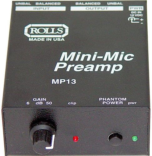


 potent nacelle
hey folks — i have a kind of conundrum.
I’m using a Circuit Playground Express’s analog out as a CV into a eurorack synth oscillator. Naturally, you can fiddle with the module so the pitch isn’t necessarily tuned to, say, a concert A.
So what I’d like is a way to auto adjust the voltage so that if i don’t have to do so by ear.
I think this means that i need to capture the audio in via some kind of ADC, but … well, here’s where my not being an electrical engineer intersects with all this.
What I’m wondering is if there’s a pre-fab board that can ADC a line-in, I think? That I could then process in the CPX (or an M4..)?
lethal slate
CPE has eight lines that can do ADC. Not sure that would be the best for tuning though.
potent nacelle
sort of, though. line in is +/-2V and as i understand the ADC is +ve only?
lethal slate
Yeah. But if you're just counting pulses to determine the frequency it may not matter.
You're looking to find the voltage out that will produce a desired frequency from your VCO?
potent nacelle
yes, that
 long birch
I have an idea for a project but would like to run it up the flag pole to see if its possible.
Using the MP3 Feather - Gordan Cole Learn Guide https://learn.adafruit.com/mp3-feather-gordon-cole. I got the Adafruit Music Maker FeatherWing Product 3357 working with a FeatherWing M0, however I would like to run it with a QT-PY, since it has I2C. I want to use the 1x4 NeoKey QT I2C in place of the manual buttons in the guide. I've tried but I can't get it to see the VS1053 so not sure if I am getting the right GPIO pins in the right order or have enough. Any Thought?
glacial spruce
Have you tried an I2C scan to see what answers?
 coral nymph
Hello guys so I was working on an open ear headphones design and was searching for speakers for this, they must be really small like max. 1 cm^2 area and have less power consumption and such, any idea where I can get this or atleast how to research about it?
PS. I am based in India so it would be great if you could recommend international websites
glacial spruce
There are some little beepers designed to be mounted on a printed circuit board about that size (note that there are different kinds, and you'd want the electromagnetic variety that work like speakers). You can also look at dynamic microphone elements, which are like tiny speakers. A third possibility is vendors of components for model railroad enthusiasts, they make some small speakers as well.
@coral nymph By way of illustration, here's a dynamic microphone element next to a US quarter to show its size: that particular one is larger than you described, but there should be smaller ones available.
 coral nymph
@glacial spruce thank you very much for your help, would definitely look into it
 violet path
I have a Stemma Speaker connected to the JST port on a Matrix Portal and I'm trying to play short .wav files but I'm not getting any sound except the occasional very short click or a noise when the CircuitPython script starts. I imagine that I'm doing the setup wrong, but there could be other problems. I haven't been able to find example code for this particular combination. Here is part of my code:
wavs = []
for f in sound_files:
    with open(f, mode = 'rb') as data:
        wavs.append(audiocore.WaveFile(data))
aud_out.play(wavs[i]) ```

 I also tried [#help-with-audio message](/guild/327254708534116352/channel/422210663507558401/) with the same result.

I have omitted some things, obviously.

(previously posted in [#help-with-circuitpython](/guild/327254708534116352/channel/537365702651150357/) )It looks like the formatting got lost, making that hard to read. My general suggestion would be to try it a piece at a time, with an individual audio file, then work up to the more complex case, so you can narrow down where things start to go awry.
violet path
Oops, sorry about the formatting. I've fixed it.
glacial spruce
Maybe just try one file to start with: ```python
with open(sound_files[0], 'rb') as infile:
aud_out.play(infile)
If that doesn't work, you may need to hand the file contents instead of a stream object to play(), like: ```python
with open(sound_files[0], 'rb') as infile:
data = infile.read()
aud_out.play(data)
Note that I'm also unsure if play() accepts a list, I'm not that familiar with that module.
violet path
wavs[i] is a list element rather than a list. The element is a stream (or buffer) object. I'll give the .read() suggestion a try.
glacial spruce
Oh, I missed that as it wasn't in a loop, which brings up the question as to what i is set to
violet path
That's one of the "omissions" I referred to. That line appears in a section of code that sets i to one of the indices of the list in the range 0 to 3.
lethal slate
I think you have to leave the .wav files open. This worked:
def load_sounds(files):
    wavs = []
    for f in files:
        wavs.append(WaveFile(open(f, "rb")))
    return wavs

kick,snare = load_sounds(["/sounds/00.wav","/sounds/01.wav"])
but using the with ...: construct didn't (no sound).
btw I'm using Adafruit CircuitPython 7.0.0-alpha.3-433-g5a4a80336 on 2021-06-25; Adafruit Feather M4 Express with samd51j19.
violet path
lethal slate
I think you have to leave the .wav files open. This worked:
```python
def load_s...
Yes, thanks, the with was closing the buffers. Leaving the files open as you show in your code worked. I'm also going to experiment with copying the data into the list and using io.BytesIO to feed it to AudioOut.play(). Thanks!
 pale plume
I have a sound looping using audioio.AudioOut and play; I'd like to switch to a new sound loop, but not in the middle of a loop of the existing sound.
Is there a way to poll the progress of playback? Or poll the number of loops? Or trigger something when the loop repeats?
I tried doing the timing by polling monotonic_ns and knowing how long the loop is, but evidently the sound's clock and the monotonic_ns clock are in different, rapidly drifting universes.
lethal slate
You could use audiomixer to fade out one sound as the next one starts.
pale plume
That is promising, thank you.
Is there a way to guarantee one ends as the new one begins?
lethal slate
Nothing I am aware of.
pale plume
And is there any insight into why (for example) loops of a 0.1-second sample do not seem to stay in phase with times when monotonic_ns() % 1e8 == 0?
glacial spruce
I doubt monotonic_ns() has an accuracy to match its precision
violet path
pale plume
I have a sound looping using `audioio.AudioOut` and `play`; I'd like to switch t...
You're aware of this idiom?
while a.playing:
   pass
You could put that inside a for loop that controls the number of loops:
for sound in list_of_sounds:
    for n in range(5):
        a.play(sound)
        while a.playing:
            pass
This would play each sound in the list 5 times.
 stiff jackal
I'm using the Adafruit Stereo 20W Class D Audio Amplifier, but only have space for one speaker, and only want to use mono audio, anyway. Can one output be unloaded, or does a dummy load need to be connected to the unused channel?
glacial spruce
I think it would be fine running unloaded.
stiff jackal
Ta. Run it for a few hours, and it seems okay.