#help-with-wearables
1 messages · Page 1 of 1 (latest)
 static fable
 supple dove
static fable
Hi, I want to mod a Casio-F91W. Which development board would be recommended for...
supple dove
static fable
Hi, I want to mod a Casio-F91W. Which development board would be recommended for...
I don't know if there is a dev board that works, but also check out https://www.crowdsupply.com/oddly-specific-objects/sensor-watch
static fable
supple dove
I don't know if there is a dev board that works, but also check out https://www....
I came across this but I'm trying to search for an alternative which is more easily available like the adafruit wearables
 grand hinge
static fable
I came across this but I'm trying to search for an alternative which is more eas...
grand hinge
static fable
I came across this but I'm trying to search for an alternative which is more eas...
That one is probably the most easily available one
 granite nexus
Does anyone have suggestion for diy waterproof mictrocontroller enclosures that I could make without a 3d printer?
I want to make a GPS dog collar but am in the middle of the woods with no makerspace/3d printer nearby for the next few weeks
All of the pre-made waterproof enclosures are way too bulky for my dog to wear around her neck
 stark storm
In the days of plastic 35mm film containers, I would use those. These days, maybe pill bottles, PVC pipe, ziplock bags, coin containers, contact lens containers, even a small bottle with a cork might work.
 untold sentinel
granite nexus
Does anyone have suggestion for diy waterproof mictrocontroller enclosures that ...
untold sentinel
granite nexus
Does anyone have suggestion for diy waterproof mictrocontroller enclosures that ...
You could do a Saint Bernard keg kind of thing with an appropriate sized plastic bottle. Cosplay for dogs! 😎
stark storm
There are lots of small containers that might suit if you have them lying around: makeup cases, lip balm cases, small petroleum jelly containers, etc. For extra water resistance, you can add silicone grease.
 cloud mantle
I reccomend any small container w/ screw cap as well 👍 pill bottles definitely the most common type
granite nexus
These are great ideas! I have some empty pill bottles here I can use so I’ll try those first!
Thank you!
granite nexus
untold sentinel
You could do a Saint Bernard keg kind of thing with an appropriate sized plastic...
My only concern there is that if it’s big enough she will find a way to chew it up
 unreal pulsar
not sure if carrying an MCU in my keyring and powering it with a battery pack in my pocket count as a wearable for here ?
untold sentinel
https://tenor.com/view/batter-explosion-fire-flame-gif-7680155
In your pocket! 😓
 unreal pulsar
untold sentinel
https://tenor.com/view/batter-explosion-fire-flame-gif-7680155
In your pocket! ...
unreal pulsar
untold sentinel
https://tenor.com/view/batter-explosion-fire-flame-gif-7680155
In your pocket! ...
no, 3x NiMH AA
not lithium obviously
how do you get power to a wearable otherwise?
bio-impedance ? ZPE ?
?
stark storm
RF harvesting?
unreal pulsar
nah I mean like surely peoples use batteries in some form to power a wearables since bio-impedance can't afaik and ZPE doesn't work afaik
and there is even more danger than pockets when a battery pack is embedded in clothes and sewn
cloud mantle
i put the batteries in mint tins
anything puncture proof should be fine
and... at normal temperatures of course
unreal pulsar
but alkalines? worst that can happen is the powder comes out
 alpine lake
is there a 5v 2A power solution for wearables that isn't just plugging into an external powerbank?
A 2A version of aidafruit’s power boost boards would be ideal
 sullen crypt
Is there a way to charge a Li-ion poly using this charger, while having the battery also connected to my wearable, like through a battery fuel guage? https://www.adafruit.com/product/4712 or would i have to disconnect the battery cable and connect it to the charger externally every time


Low cost Lithium Polymer batteries have revolutionized electronics - they're thin, they're light, they can be regulated down to 3.3V and they're easy to charge. On your phone, ...
 south lark
For 4712 you would have to recharge it separately each time yes.
259 is a little bigger but does have pass through charging. You can use it while charging.
I have a couple of 259’s they’re great.
sullen crypt
ohh i see, so if i hook up my battery to the 259 and then pass that through my fuel guage i can charge while its hooked in no problemo
south lark
Yes

This is a Lithium Ion and Lithium Polymer battery charger based on the MCP73833. It uses a USB mini-B for connection to any computer or 'USB wall adapter'. Charging is performed in ...
sullen crypt
thanks so much thats great!
too bad i didnt see this one while i was ordering my parts haha
south lark
Just make sure the battery you use has the correct polarity. Best to get batteries from Adafruit as the wiring ensures it’s compatible. Lot of batteries on Amazon have plus and negative reversed which could fry the board.
sullen crypt
yes i have a 1578 500mh!
south lark
There are warnings about that all over adafruits learn guides, unfortunately it happens often.
Ok nice then you’re all set.
You’ll need a mini b usb cable for it. It’s an older charger but excellent one. No usb c.
sullen crypt
ive got one lying around so thats good
south lark
Maybe they’ll update the design for that one someday. The 259 is still years later my go to charger.
sullen crypt
also quick question, i have an on-off toggle switch to, but its only got 2 prongs, im not sure where that goes to stop the power flow?
south lark
Because it has pass through charging. You can use it while charging. Not all charger boards can do that.
As in push button toggle switch?
 south lark
Just means ground and power.
What do you want to stop power to/from? The battery? Or your load?
sullen crypt
well i just want to be able to turn it on or off i guess? the battery
this is my first time making something like this so im not really sure where the best place to use that is
south lark
Hmm your going to have to cut the power wire in half that goes between the battery and fuel gauge.
Solder each end of the cut half to the power switch prongs.
sullen crypt
ok thats not so bad
south lark
That’s called a power side switch.
You could also do it to the ground wire instead which is known as a ground side switch.
Up to you, either way will work.
sullen crypt
hmm whats the difference in usage between the ground and power switch?
its there some advantage to one or the other?
 rancid plank
it's usually better to switch power than to switch ground, especially when some parts might be powered at the same time that others are not
south lark
At these low voltages there’s not much difference. You’ll see it become more important at higher voltages and current to help prevent electrocution.
If your switch can handle the voltage then go with power side no problem.
sullen crypt
ok sounds good, thanks for the advice!
south lark
It’s only 3.3V for most Adafruit stuff which is even lower than most 5v Arduino stuff. Pretty much any little electronic switch will handle 3V without flinching.
Even the tiny tiny buttons will do 3V safely.
sullen crypt
it says 50V lol but i feel like thats a typo and it should say 5
south lark
Lol, well then definitely no worries there.
stark storm
alpine lake
is there a 5v 2A power solution for wearables that isn't just plugging into an e...
This might do: https://www.pololu.com/product/4012
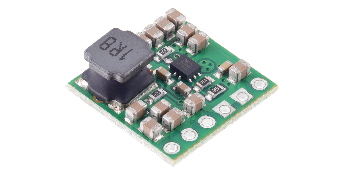
This compact (0.6″×0.6″) switching step-up (or boost) voltage regulator efficiently generates 5 V from input voltages as low as 1.3 V and handles continuous input currents up to around 4 A. (Note: minimum start-up voltage is 2.7 V, but it operates down to 1.3 V after that.) The pins have a 0.1″ spacing, making this board compatible with standard...
rancid plank
electromechanical switching stuff usually doesn't bother to go below 50V or so in contact ratings; it's not difficult to get at least that high a voltage rating, and it's kind of pointless to separately rate it for lower voltages
stark storm
There are two major classes: high voltage/high current ones with silver contacts, and low voltage/low current ones with gold contacts. It's necessary to keep the contacts clean, and the way this is done is different for different power levels.
south lark
The metro mini will do 5v but it’ll burn up at 2A. Think it only does 500ma.
stark storm
If you run low power through silver contacts, they'll get dirty and gain resistance. If you run high power through gold contacts, you'll vaporize the coating.
There are some manufacturers that offer gold-over-silver contacts, so if you use them in low power, the gold does the work, if you use them in high power, the gold burns away and then the silver does the work. They cost more, but if you don't want to keep track of multiple types, it can make sense.
stark storm
south lark
The metro mini will do 5v but it’ll burn up at 2A. Think it only does 500ma.
That's not how current works. It's the amount available, but the load determines the amount that is actually drawn. Just like the outlets in your house, which can deliver 13-15A in most cases, but if you plug in a 7 watt night light or a 5 watt phone charger, they'll only draw the current they need
south lark
They specifically asked for 5V 2A?
stark storm
I thought they asked for something like a powerboost that could handle 2A.
south lark
Oh I didn’t see the 4A rating on the boost converter you recommended.
Yeah that’ll work
Wasn’t saying your solution wouldn’t work, was just trying to think of a wearable board that might get close. There really isn’t one to my knowledge.
Might do 800ma max but not close enough for 2A for a big led strip for example.
With that much power you’re going to need a big battery or it’s going to run out of juice quick.
cloud mantle
https://www.adafruit.com/product/1385
I have one of these and Ive used it with a 9v nimh RC battery

Your power supply problems just got SOLVED! This little circuit board may look tiny but inside is a high efficiency DC/DC step-down converter which can output up to 3 Amp at 5V without the ...
or not. if boost is specifically required
 magic bridge
Any resources on building VR hardware?
I was taking apart my ps vr the other day. It was quite bulky but built decently. The electronics were quite small relative to its size. I was thinking maybe if you could somehow offload that somewhere else and just beam the data to headset. Then you could maybe reduce its bulk as well as apply some techniques to increase the FOV
facebook's new holographic lens
 stark storm
You're right about the electronics being a small part of it: because of this, offloading the processing isn't likely to buy you much improvement. However, there are various ways to make the optics more compact (Facebook hardly originated aspheric or holographic optics, they've been available for many years)
magic bridge
yea I havent seen it be used for a fully immersive experience though, but AR seems to work well enough
I cant seem to find the types of lcd screens they use. Its quite insane, something like a 1600p resolution display in a 2-3 inch form factor
the best i could find was a 240x240 https://www.aliexpress.com/item/1005002311123532.html display

aliexpress.com
Smarter Shopping, Better Living! Aliexpress.com
stark storm
They are kind of specialty parts. I had been looking at the Sony ECX335B previously for a similar application
magic bridge
hm that seems like a pretty nice one. https://www.aliexpress.com/item/1005001703718786.html this too, maybe with a custom board. Guess I wasnt searching hard enough
 modern forge
I'd like to make a relatively simple, preferably low-power wearable (pendant or pin about 2"/50mm dia by 025"/6mm thick). All it needs to do is twinkle 3 or 4 NeoPixels in various color combinations. Points for it being rechargeable enough to run several hours. What are my best options for hardware (controller, battery, etc)?
 fluid cypress
modern forge
I'd like to make a relatively simple, preferably low-power wearable (pendant or ...
fluid cypress
modern forge
I'd like to make a relatively simple, preferably low-power wearable (pendant or ...
I'd look into the ATTiny line. I think you could cobble together parts of a neopixel lib and get something working
rancid plank
what languages are you comfortable with working in? do you need a battery charger built-in?
modern forge
rancid plank
what languages are you comfortable with working in? do you need a battery charge...
I'm thinking, yeah, built-in battery charge (was looking at Feathers for that reason). Most comfortable with C, C++, Java. I've written Arduino code before, so not an issue. Never tried Python but could probably pick it up.
The goal is to post a 3D-printable model, plus assembly instructions and source code. I'd prefer to make it as easy as possible to assemble and use so that others can remix as needed.
rancid plank
if you want tiny, i've heard that Gemma M0 and Flora are good starting points. downside is that they lack built-in chargers. beware of older versions of Gemma (and Trinket): they use bit-banged USB, and the timing is too coarse to work with a lot of modern computers
modern forge
rancid plank
if you want tiny, i've heard that Gemma M0 and Flora are good starting points. d...
Yeah, something like a Gemma with built-in charging and mounted NeoPixels would be ideal, but I doubt that's going to happen anytime soon. 🙂
I was also looking at the QT Py with the BFF add-on, but wasn't sure what the total thickness of those stacked together would be. Those, plus a small LiPo and maybe a NeoPixel Jewel would probably be enough to get it going. Minimal wiring required, and a handy charging port and power switch built in.
rancid plank
modern forge
Yeah, something like a Gemma with built-in charging and mounted NeoPixels would ...
yeah, that could work if you're going for as small as possible. there is a tradeoff with size vs simplicity for a mostly single-board solution with battery charging like a Feather, though. you could prototype with a Feather and then work on making a smaller multi-board assembly with a QT Py or Trinket M0 plus BFF
 knotty hollow
standard "thermal runaway" warning when mixing LiPos with wearables applies here
rancid plank
that is a good point. is this for an educational setting? if so what ages of students? (Circuit Playground Express, etc boards lack battery charging partly for LiPo safety reasons)
modern forge
rancid plank
yeah, that could work if you're going for as small as possible. there is a trade...
Yeah, I agree that the Feather is a simpler solution, and the power switch is just a nice-to-have. A simple touch pad to turn the lightshow on/off is probably sufficient. So, Feather + LiPo + Jewel it is, then. Thanks!
modern forge
rancid plank
that is a good point. is this for an educational setting? if so what ages of stu...
Mostly wearable for adults, so age probably not a factor.
modern forge
I think I've come up with a layout that won't be too awful. Yellow=LiPo, Red=Jewel, Green=Feather. Minimum dimensions are 64mm dia × 12mm h. Intent is to print in translucent filament with an opaque cover with a cutout design. Hoping the filament diffuses the light enough to light up the design.

 sharp forge
Anyone been able to source any flexible batteries? These look super cool but there doesn't seem to be a way to buy them.

J.Flex is a flexible thin film lithium ion battery that can be customized to wearables, medical devices, monitors, and more. Powerful and thin, the J.Flex can provide high energy flexible battery and liberate product design, allowing for more creativity, adaptability, and user-friendly experiences
 jovial nymph
Have you tried contacting them? Let me know if you do, I'm interested too.
sharp forge
I haven't yet
 short fjord
Not from that supplier but I got some from a different one
I forgot the name though
ah no found it
ProLogium is a solid-state battery manufacturer that is leading in the commercialization of safer EV batteries with higher energy density and superior performance. Following its first shipment of lithium-ceramic battery(LCB) in 2014, ProLogium's R&D and production capabilities for SSBs have been verified by various markets.
I don't know if they still make them - was many years ago
And you can ask these if they have some. I got some curved batteries from them previously https://www.grepow.com/
 zealous dagger
It there a way to make a small camera that I can wear over my eye?
I am making a portal cosplay and I want to make the zoom effect real by making a monocle to wear on my right eye (as it is my non-dominant eye)
I do want to design it to fit the aperture science aesthetic but have it small and light enough to not be cumbersome
stark storm
You could do it optically, but it's also possible to use a tiny camera (like a cell phone camera) and miniature monitor+optics (like VR goggles) and just transform the image on the fly as needed.
zealous dagger
stark storm
You could do it optically, but it's also possible to use a tiny camera (like a c...
I was thinking about something like that. Using a run cam, an Adafruit tft board and a double convex lens but all that stuff is over my head
stark storm
It's one of those cool ideas that's not simple from an actual implementation standpoint.
But the lens situation isn't very complicated (think about those "VR adaptors" you strap onto a phone, I think the lenses in those aren't complicated).
Or just grab a viewfinder from an old camcorder.
 fluid chasm
Im trying to build sunglasses that take a signal from my phone and project it onto the lense so i can read lyrics secretly to sing along. My budget is very low so I was thinking I can use the lcd panel on a laptop or old phone and connect it to micro usb, micro hdmi, or usb c connecter and connect it to my phone. Can I cut the lcd panel carefully to make it an adequate size and what other connectors do I need to connect the panel to my iphone?
fluid cypress
Hey there, fun projects, we usually don't multi post though. Hope you get help!
fluid chasm
fluid cypress
Hey there, fun projects, we usually don't multi post though. Hope you get help!
sorry im new to discord and got it for this project
fluid cypress
I wouldn't stress, just know it's an etiquette thing around here. May even be a rule
 light wigeon
i'm working on modifying the adafruit cospaly wings: https://learn.adafruit.com/animatronic-cosplay-wings to fit with a fursuit i'm making

i'm thinking about doing a split design, where the backplate is split vertically down the middle and has clips to hold them together
and running cables to around the front to connect each half. this is required to get it to work with the rest of the fursuit
is there anything i should be concerned about with the longer cable runs for the servo motors?
additionally, if i use usb battery pack. can i just wire the USB 5v pin into power input servo controller?
stark storm
The servo control signal is pretty simple and robust, it should be fine, unless you run into problems with noise/interference. Powering the controller with 5V from the power bank should be fine. However, if you're also powering the servos with that 5V, you may have to watch out for noise/sags from the servos interfering with the logic supply – you may need a decoupling network of some sort.
light wigeon
stark storm
The servo control signal is pretty simple and robust, it should be fine, unless ...
thanks for the reply
 lofty lily
What type of jig fits in these potentiometers?
https://www.mouser.com/datasheet/2/15/alne_s_a0010160466_1-2258480.pdf
It is very small, too small to FDM print from what I have tried
Are there some sort of shafts that are able to be bought for it? Or how do I get a shaft for it.
stark storm
lofty lily
What type of jig fits in these potentiometers?
https://www.mouser.com/datasheet/...
Those are more encoders/sensors than potentiometers (although they basically work similarly). They accept a 3.5mm or 4mm D-shaped shaft, should be FDM printable.

 quiet dune
I'm working on a wearable that makes use of the light sensor on the Circuit Playground Bluefruit. I calibrated the sensor by having it print out values to the serial terminal while plugged in to my computer and it works fine. Since it's a wearable though, it needs to run on battery, and the calibration is messed up when running on battery. I suspect this is because my computer is supplying more power than the battery does (I'm using 3 brand-new AAA batteries). Is there any way to fix this so that it works regardless of the power source?
Please ping if replying
stark storm
quiet dune
I'm working on a wearable that makes use of the light sensor on the Circuit Play...
The basic idea is to provide a regulated voltage to the analog converter's reference input.
 mellow bobcat
Helloo
I'm making a working chainsaw man helmet but don't know what kind of motors to use

I wanted to make it a bit realistic so I bought some bike chains so the motor should be powerful enough for that
Would a 12v or 24v dc motor work?
I think 24v motors are a bit expensive so not sure about that unless its the only option
stark storm
Yeah, ordinary 12V or 24V DC motors should work fine
 pure echo
I’m wondering if spinning a bike chain on your head is safe…
Ideally you find a smaller motor with its speed geared down…?
 cyan gate
likely not
fluid cypress
Yeah a bike chain is still a chain
Sounds risky. I'd look into how movie props do it
Likely to be much safer
mellow bobcat
pure echo
I’m wondering if spinning a bike chain on your head is safe…
Well I won't be spinning it in a really high speed
Just fast enough to look cool
mellow bobcat
stark storm
Yeah, ordinary 12V or 24V DC motors should work fine
Would 12v work good enough? Or should I use a 24v?
mellow bobcat
fluid cypress
Sounds risky. I'd look into how movie props do it
If the movie has a budget they would 3d print it or make it out of plastic probably
mellow bobcat
pure echo
3D printed chain?
3d printed would work great but I don't have a printer and the shops that print stuff for u are a bit expensive. And cable chain is not really realistic looking idk
I' make it as safe as possible dw
stark storm
mellow bobcat
Would 12v work good enough? Or should I use a 24v?
It depends on the motor, drag, effect you're looking for, etc., but I'm guessing a 12V motor would work fine
stark storm
mellow bobcat
3d printed would work great but I don't have a printer and the shops that print ...
Some people have used ball chain, which looks reasonable and is lightweight, inexpensive, and not sharp. However, bike chain is probably reasonable, IMHO
mellow bobcat
Ball chain? I'm making a fake chainsaw mate not a kids toy lol
mellow bobcat
stark storm
It depends on the motor, drag, effect you're looking for, etc., but I'm guessing...
Okayy thank u
I hope it works 🤞
 turbid moth
mellow bobcat
If the movie has a budget they would 3d print it or make it out of plastic proba...
turbid moth
mellow bobcat
If the movie has a budget they would 3d print it or make it out of plastic proba...
Most movies don’t actually use moving chains in their chainsaws. Chainsaws are absurdly loud even when electric, and ruin any sound recording. So the chainsaws often aren’t running, and often don’t even have chains on them, it’s edited in later. Because editing the video to add a chain effect is much much easier than cleaning up the audio ruined by the sound of a running chainsaw. Most chainsaw sounds in movies are also added later, it’s the job of the foley artist. In haunted houses almost always the chain has been removed or disabled from the saw.
 heady iron
So I have a head lamp that fits a neopixel ring in it perfectly. I want to set it up so that I can turn a potentiometer and change the colors of the neopixel ring. What I need to know is what is the smallest board I can use that will run circuit python?
supple dove
heady iron
So I have a head lamp that fits a neopixel ring in it perfectly. I want to set ...
Take a look at the QTPY boards, like https://www.adafruit.com/product/4900
mellow bobcat
turbid moth
Most movies don’t actually use moving chains in their chainsaws. Chainsaws are a...
Yeah I was gonna say the same but the convo would get out of topic and didn't want to ramble. Most movies just use cgi. If it was an old movie they would probably use either a real one or modified one that isn't loud or dangerous. They wouldn't use 3d printer at all btw (unless its an indie or low budget movie or something) idk why I said that lol. But they might make it out of plastic or something
heady iron
supple dove
Take a look at the QTPY boards, like https://www.adafruit.com/product/4900
Thank you!
 hazy smelt
mellow bobcat
Yeah I was gonna say the same but the convo would get out of topic and didn't wa...
hazy smelt
mellow bobcat
Yeah I was gonna say the same but the convo would get out of topic and didn't wa...
Well and the thing to remember about movies that you simply can't do in cosplay. Movies can control where the audience is looking from. So it's nothing to just have a chain for a few shots to give the idea, and then no chain for all the shots where you wouldn't be able to see it anyways.
 daring helm
Hello, new here and I have a couple of questions. So far I've had a really good time with the Adafruit Soundboards, they're perfectly simple and with the MAX98306 can output some really nice sound at decent volume. However, I need this latest project to have at least 1 pretty loud sound effect. I take my work to conventions and I'd like people to hear one or two of these sound effects while not having to stand right in front of it, which is what I'm currently getting with most of these projects even with the amp. I recently purchased the 20W speaker Adafruit has in stock, along with the MAX9744 amplifier, but I'm unsure how to hook it up to the sound board. Should I power it separately or can I use the VDD and GND pins like you do with the MAX98306 to power both the board and the amplifier+speaker? I'm only using one speaker for this, if that's relevant, I know it says it can power 2, wondering if that means can power 2 or should/must power two.
I'm assuming I can do what I'm thinking and attach it just like I did with the MAX98306 and power it all with the standard 3xAA, is that accurate? Should I do something differently? Sorry for the wall of text 😅 Just want to make sure I don't break anything, I'm still new to this kind of stuff and learning a lot
stark storm
I think you can power them together (but I'm not certain). You don't have to use both speakers, that's fine.
daring helm
Any ideas why my brand new soundboard is outputting sound so low i have to have my ear next to the speaker just to hear it? I've tried it on 3 different speakers with the same result. Powering as usual with 3xAA, as far as I know I haven't done anything different than I've done in the past. Haven't even hooked up the amp yet or anything, its just the soundboard connected to the battery pack and two speakers. My last one actually did this too but that was after overpowering it so I figured it was just broken. But to have a new one suddenly do this is very strange.
fluid cypress
Which board?
daring helm
the 16mb mini soundboard
fluid cypress
This one? https://www.adafruit.com/product/2220 ?

Would you like to add audio/sound effects to your next project, without an Arduino+Shield? Or maybe you don't even know how to use microcontrollers, you just want to make a sound play ...
daring helm
Yes but the version without the audio jack. I have separate speakers to wire up to it directly
I have another one I got just in case because I'm in a time crunch right now and didn't want anything to go wrong so I grabbed two and I'll test that one in a little bit. But I wasn't actually expecting anything to happen lol oof
Hopefully its just me being dumb, I'd totally take that over something actually wrong lol
I'm looking over the Learn page again just in case I missed something
AH I found it
It was a my bad thing
The speakers I'm using to test are 4 Ohm, the line outs are for 30 Ohms, so I just need to connect my amplifier to it
Glad it was just a silly thing. Thank you for the quick reply anyway :)
fluid cypress
I don't think I did much but you're welcome! Glad it worked out.
 bold hazel
adafruit your "Adafruit Daily" email today is for a discontinued product. It looked pretty cool though.

 fair chasm
What's discontinued? I see the Gemma kit is out of stock, but I don't see anything marked discontinued on the featured products list
 ancient magnet
The soft potentiometer (https://www.adafruit.com/product/2273) is. But there is a replacement listed that is available.
The replacement is https://www.adafruit.com/product/178

Manufactured by Spectra Symbol, these are nice little ribbon controllers (also known as 'soft potentiometers') with an adhesive backing.There is a nominal 10K resistance across the ...
fair chasm
Ahh... that's unfortunate
light wigeon
Hi, can someone please help me with the best electronics to use for my wearable project? I want to create a wearable body suit with choosing the right electronics for it? I want to create a bodysuit for a dancer, that will play sound based on the movement of the dancer. I would like make the sound change based on the movement of the wrists. I would like to also incorporate 8 touch sensors spread around the dancers body, that would also generate a sound if touched. Each area with the touchpad should also lit up when touched. Could you help me witht the electronics I could use for this project? 🙂 Thank you
 amber widget
light wigeon
Hi, can someone please help me with the best electronics to use for my wearable ...
amber widget
light wigeon
Hi, can someone please help me with the best electronics to use for my wearable ...
Hello and welcome to our community! I wanted to let you know that most of the folks who help out here are community members volunteering their time around their life obligations, so they help out when they can. Please don't be discouraged if you don't receive a response quickly. This channel is not as widely watched by folks who may be able to help. We definitely discourage cross-posting to multiple channels, but in this case I'm suggesting it as an option. You might receive a quicker response in #help-with-projects. No guarantees though. It's completely up to you whether you would prefer to wait for assistance here, or post your question to the projects channel. Good luck with your project, and again, welcome! 🙂
light wigeon
amber widget
Hello and welcome to our community! I wanted to let you know that most of the fo...
Thank you, I will try 🙂
stark storm
light wigeon
Hi, can someone please help me with the best electronics to use for my wearable ...
There are a variety of sensors that could work (force sensors, flex sensors, stretch sensors, etc.). For the touch sensors, you can use either conductive ones or capacitive ones (or perhaps light sensors that detect when they're covered, or proximity sensors). From an electronics standpoint, it's not a very demanding application, so a variety of processors would be suitable.
 terse moon
stark storm
There are a variety of sensors that could work (force sensors, flex sensors, str...
terse moon
stark storm
There are a variety of sensors that could work (force sensors, flex sensors, str...
I found out the hard way that force sensors do not in fact detect midichlorians
🫣
 rapid radish
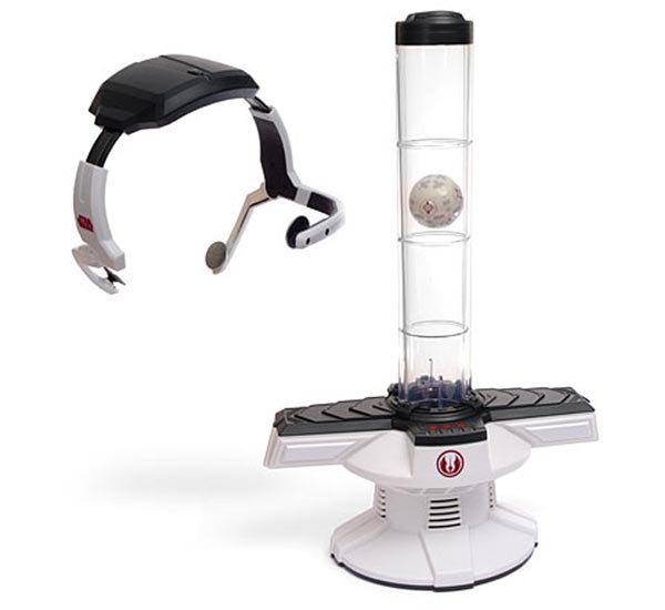
The Star Wars Force Trainer allows you to control a Jedi Training Remote with your mind, by tapping into cutting-edge brainwave technology.
 hexed root
rapid radish
https://ologicinc.com/portfolio/star-wars-science-force-trainer/
hexed root
rapid radish
https://ologicinc.com/portfolio/star-wars-science-force-trainer/
That’s actually really cool. If you can get your hands on that or a mindflex toy, you can attach an hc-05 to the serial lines, connect that hc-05 to a microcontroller, and use the whole thing as a crude-ish eeg headset. I’ve done it. The force trainer also looks like it has a better system than the mindflex’s band to provide skin connection.
 livid solstice
Hi, I am planning a project where a need to power a few led (probably a 15 cm long strip of Dotstar LEDs, which are about 25 LEDs) and only have a pretty small space for control/power. So my question is what microcontroller I should use and what kind of battery. I've been thinking of using a Feather V2 because it's pretty small and has Bluetooth (which I need in my project). And for power I was thinking of using a lipo (I need as much runtime as I get), but I don't know what lipo I should use in terms of voltage (I guess a 5v, so I can power the LED from it and step the voltage down for the microcontroller or use a separate one).
I was thinking of using a lipo from Adafruit but will this work because the output of them is 4,5V -3,7V is this enough for the 5V LEDs?
So what do you guys recommend to use?
stark storm
livid solstice
Hi, I am planning a project where a need to power a few led *(probably a 15 cm l...
LiPo cells are all the same voltage, basically. They just vary in capacity. While the LEDs are specified for 5V, most of them will run fine from lower voltage available from LiPo cells. This is really handy for compact projects like yours, and as a bonus avoids needing to do level shifting of the signals controlling them.
livid solstice
stark storm
LiPo cells are all the same voltage, basically. They just vary in capacity. Wh...
ok thanks 🙂
 pine notch
hello
i need help and guidance on building a cyberpunk mask
i can buy the parts and might need guidance on what to solder and where
please
i want to have a feather board that controls LEDS with phone app (already found one)
also need to implement extra code so i can use blutooth with wired bone headphones onto the feather board
also a microphone on the inside of the mask that goes to speakers so people can hear me
stark storm
I'm unsure if any Feathers support audio over Bluetooth
pine notch
could use this

Ameba RTL8722DM Mini Board (AMB 23) is a devkit for a different family of WiFi/BLE-integrated chipsets from RealTek. As more chip companies come out with their "All in One IoT" ...
and do on board tracks
:/
or this

MakerHawk 2pcs Bluetooth Audio Receiver Board BT 5.0 Stereo Audio Amplifier 3.7-5V Car Speaker Amplifier for DIY
i dont want to have to connect 2 boards every time
:/
one for led, one for music
i will if i have too
terse moon
Just a heads up on the Realtek board, that chip I'd recommend for advanced users.
it's a good chip, but lots of documentation is hidden behind NDA
the SDK is public on Github though so there's that
pine notch
pine notch
i dont want to have to connect 2 boards every time
i can live with that
🙂
i think i have all the parts picked out
just need a schematic
stark storm
Most boards will communicate with each other via SPI or I2C, just a few wires
pine notch
ahhhh
sweet
now if i knew how to do that lol
😛
i can learn online
also i need a 2 amp to power 2 1 amp speakers
only can find a 3 amp
wait

Dimensions: 21.5 x 14.5 x 7.9mm, Weight: 9.6g Impedance: 8 ohm, Re: 5.8 ohms Power handling: 1 watt RMS/2 watt max, Le: 1.26 mH Frequency response: 300-19,000 Hz (but will vary with what you use as the transducer surface) SPL: 90.1 dB 1W/1m (but will vary with what you use as the transducer surface)
these require amps too
ughhh
2 of thos and one loud speaker
but can one amp power head phones and a loud speaker independently
stark storm
By and large, I don't recommend amazon parts for beginners, they tend to be sketchy. However, you don't need Bluetooth to send audio to a local transducer (I had incorrectly assumed you already had a Bluetooth transducer speaker)
You can often drive headphones directly from things like a music shield, but you will want an amplifier to drive a speaker or transducer
pine notch
ok just incase theres confusion , i want a microphone to a loud speaker and blue tooth to phone so i can use the bone headphones
can i use the same amp
like a 3W amp for 1amp speaker and 2 bone headphones at 1 amp each
but it would have to have 2 channels
stark storm
What do you mean by "1 amp speaker" Do you mean 1 amplifier, 1 ampere, or something else?
pine notch

Hear the good news! This wee speaker is a great addition to any audio project where you need 8 ohm impedance and 1W or less of power. We particularly like ...
sorry
1 watt speaker
skipped breakfast
😛
stark storm
You may be able to parallel things to drive two of them from a single amplifier, as long as you want to send the same signal to both of them and the amplifier supports the lower-impedance load.
pine notch
sweet
let me draw up a quick blue print

Lol don't laugh
Thos are fans top right
I'll make a better one latter
pine notch
stark storm
You may be able to parallel things to drive two of them from a single amplifier,...

Listen to this good news - we now have an all in one digital audio amp breakout board that works incredibly well with the Raspberry Pi! If you're looking for an easy and low cost ...
i prob cant use this for the mic to speakers and to listen to music
dont think its a dual channel
stark storm
That's an I2S amplifier, which would only work with a system that can generate an I2S signal.
 dapper turtle
Hi all, I’ve been working on a wearable device that will record an input at set intervals (10-30mins), which I need to log, then send to another device (preferably a phone) at the end of the day/week. I have been using a QT Py SAMD21, but have hit ram issues and was reliant on a cable to retrieve data which is OK. However, now that I’m in the market for an upgrade, can anyone confirm that one of the newer QT boards will do all this?
Like to have features:
- On-board battery charging a big plus
- RTC (accurate to +/- 2mins/week)
- Wireless data transfer options
- Low power modes
Happy to use Circuit Py or Arduino to code.
pine notch
stark storm
That's an I2S amplifier, which would only work with a system that can generate a...

Adafruit Industries - Makers, hackers, artists, designers and engineers!
I discovered something fascinating while browsing around the other day: headphones that transmit sound directly to your skull. This method of sound transfer has been dubbed bone conduction. All you…
He used the Stereo 3.7W Class D Audio Amplifier – MAX98306
That's the one I need for the headphones
Now i need one for 1 w speaker or 2w for two speakers
Can't find a 1w Amp so prob will just use 2 speakers
Or the 2.5w Amp on adifruit would work for one 8ohm speaker
Uses 1.5 W at 8ohm

This super small mono amplifier is surprisingly powerful - able to deliver up to 2.5 Watts into 4-8 ohm impedance speakers. Inside the miniature chip is a class D controller, able to run ...
stark storm
pine notch
https://www.adafruit.com/product/2130
That 2.5W amplifier is a good choice, it's a single channel, but supports 4Ω loads, so could drive two 8Ω speakers or transducers in parallel
ancient magnet
dapper turtle
Hi all, I’ve been working on a wearable device that will record an input at set ...
I would suggest https://www.adafruit.com/product/5000 and for RTC https://www.adafruit.com/product/2922 or https://www.adafruit.com/product/5189.

What's Feather-shaped and has an ESP32-S2 WiFi module? What has a STEMMA QT connector for I2C devices? What has your favorite Espressif WiFi microcontroller and lots of Flash and RAM ...

A Feather board without ambition is a Feather board without FeatherWings! This is the Adalogger FeatherWing: it adds both a battery-backed Real Time Clock and micro SD card storage to any ...
The ESP32-S2 provides LIPO battery charging and wifi transfer. You might also look at using Adafruit IO https://learn.adafruit.com/welcome-to-adafruit-io to log your data.

Adafruit Learning System
Want to connect your project to the Internet? Start Here!
dapper turtle
ancient magnet
I would suggest https://www.adafruit.com/product/5000 and for RTC https://www.ad...
Thanks! I was hoping to stick with the QT form factor. Does the ESP32 have anything built in that will keep time to a few minutes a week (assuming constant power)?
Adafruit IO looks good, I just haven’t seen an example where the data is uploaded in bulk (data for the day/week with time-stamps, for example) - Is this possible?
ancient magnet
dapper turtle
Thanks! I was hoping to stick with the QT form factor. Does the ESP32 have anyth...
None of the QT PY form factor will have battery charging which was the 1st thing you mentioned. If you aren't concerned about a few minutes, you, you might be OK using millis() or time.monotonic. I don't believe that Adafruit IO provides bulk upload.
untold sentinel
dapper turtle
Thanks! I was hoping to stick with the QT form factor. Does the ESP32 have anyth...
Check out the seeed nrf52840. Battery management, ble and circuitpython. 👍🏼
 steel estuary
dapper turtle
Thanks! I was hoping to stick with the QT form factor. Does the ESP32 have anyth...
steel estuary
dapper turtle
Thanks! I was hoping to stick with the QT form factor. Does the ESP32 have anyth...
I have one of these...? https://www.adafruit.com/product/5397 and a QT PY rp2040
Is your QT Py all alone, lacking a friend to travel the wide world with? When you were a kid you may have learned about the "buddy" system, well this product is kinda like that! A ...
It stacks on top of it (or can) but I might be... ah, no it charges a lipoly battery too. I just never tried. I have a separate lil stick for that.
dapper turtle
steel estuary
It stacks on top of it (or can) but I might be... ah, no it charges a lipoly bat...
I did see that one - unfortunately I just don’t have the space for it. Thanks anyway though!
dapper turtle
untold sentinel
Check out the seeed nrf52840. Battery management, ble and circuitpython. 👍🏼
Ah, I knew I’d seen something in the XIAO / QY form factor with battery management! Thanks, I take a look at that one.
 boreal olive
bold hazel
https://learn.adafruit.com/textile-potentiometer-hoodie
boreal olive
bold hazel
https://learn.adafruit.com/textile-potentiometer-hoodie
I love this.
 uncut cave
Hello, I'm having trouble figuring out what is wrong with my Flora project. When I upload the sketch and test it out while plugged in everything works, but when I unplug it and power it again the sketch suddenly stops working. Does anyone know what went wrong?
to be specific my wearable is supposed to vibrate in response to button presses from the Adafruit bluetooth LE app, I'm using the Flora bluefruit LE module to have the device and app communicate
stark storm
uncut cave
Hello, I'm having trouble figuring out what is wrong with my Flora project. When...
To clarify, is it working with USB but not on battery? If so, that can happen for a few different reasons, but one I've seen a lot is it's trying to initialize a serial connection for debugging, and the battery doesn't provide a serial connection.
uncut cave
stark storm
To clarify, is it working with USB but not on battery? If so, that can happen f...
It works with USB but not on battery yes, but I think the problem is a unrelated to the battery. I've tried just plugging it in through USB without uploading the sketch again to see if its an issue with voltage and it seems that I have to keep uploading the sketch to get it to work.
stark storm
Hmm, maybe more of a reset issue then
uncut cave
stark storm
Hmm, maybe more of a reset issue then
Thanks for the reply, it helped me figure out what I did wrong. It works as intended now with USB, but it seems now I do indeed have an issue with the battery.
It looks like the Flora board is not able to read input coming from the bluetooth module if its powered via battery. Though it can connect to the app indicated by the blue light.
 woven valve
Anyone know how to port files onto a Badger 2040?
stark storm
If you have it configured with CircuitPython, it presumably appears as a mass storage device when connected to a computer via USB, and you can just copy files into it like any other external storage.
woven valve
Another Badger2040 problem, import badger2040 seems to not be working once I load CircuitPython onto it
stark storm
You may need to install some libraries
rancid plank
what code are you using that depends on badger2040?
 onyx ibex
I have everything set up (I think) using the gemma.mo, but when I try to get it to run I just keep getting the double blink red and nothing on the rings
stark storm
Arduino, CircuitPython, or something else?
 unkempt marten
Hey Everyone,
Questions about Voltage, Inductive Coils, and Wireless LEDs:
Looking at this guy, 5V input, inductive coil:
https://www.adafruit.com/product/5140
If I have a 5x AA battery pack, with 1.2V nickel rechargeable batteries, will the 6V fry the 5V circuit? Is there any overvoltage protection?
https://www.adafruit.com/product/5140#technical-details
What do you think?
Is it safe to get a 5x AA battery pack, filled with 1.2V batteries, to power the 5V inductive coil?:
https://www.adafruit.com/product/3456
(bonus Q, what would be a compact battery solution with good mah capacity to power the 5V coil? 5V button cells in parallel maybe? -- the project is a wearable project)
1.5
What is the mah draw on the 5v coil?
https://www.adafruit.com/product/5140#technical-details
https://www.adafruit.com/product/1407
Inductive Charging Set
This is a 9V input, 5V output
Could I use these coils, instead of charging, could I use each coil to power wireless LEDs instead?
I suppose one coil transmits power, the other receives power - so no?
If no, is there a way to get both coils to 'output' power?
What voltage can these wireless LEDs handle?; I can't find their limit via the technical description link; I suppose the large wireless LEDs work with the 24V inductive coil, so they can probably handle any inductive coil Adafruit sells? But what about the small guys?:
Small LEDs:
https://www.adafruit.com/product/5353
https://www.adafruit.com/product/5353#technical-details
Large LEDs:
https://www.adafruit.com/product/5574
https://www.adafruit.com/product/5574#technical-details
I've searched online a bit and even called my mentor. Hoping y'all can help fill in some gaps
 analog tundra
make a feather wing
like a pair of wings with neopixels and servos to move the wings powered by feathers and featherwings
stark storm
unkempt marten
Hey Everyone,
Questions about Voltage, Inductive Coils, and Wireless LEDs:
1.
...
As for the wireless LEDs, they're powered by a magnetic field, so I'm not sure what you mean by voltage here. Maybe you'd be better off describing what it is you're actually trying to accomplish.
pure echo
unkempt marten
Hey Everyone,
Questions about Voltage, Inductive Coils, and Wireless LEDs:
1.
...
-
There are, unfortunately, no data sheets or specs for this guy, so when in doubt err on the safer side. I would be surprised if this didn’t power with 4x (4.8V) but there’s no way to tell besides physical testing. I would personally look for a DC-DC converter to get a 5V output if you’re especially concerned with voltage levels. Check out https://adafruit.com/product/4654 for one such product.
-
Only the transmitter would be capable of powering inductive LEDs. The receiver does not have circuitry to take a DC input or output an AC output to the coil.
-
Since there is only a single coil and what I assume is a rectifier, there isn’t a maximum voltage, or any input voltage even. A more powerful coil will drive more current, but I’m not aware of a spec for how much magnetic field will drive enough current to damage them. A wearable coil certainly won’t…

This adorable little board will come in very handy whenever you need a good amount of 5V power. It's the size of a linear regulator, but it's actually a mini-booster! Input 2-5VDC on ...
unkempt marten
stark storm
As for the wireless LEDs, they're powered by a magnetic field, so I'm not sure w...
The voltage input circuitry which sends power to the coil.
Don't want to overvolt & fry the circuitry on accident
unkempt marten
pure echo
1. There are, unfortunately, no data sheets or specs for this guy, so when in do...
A booster is a neat idea.
Will see how long some batteries last powering the coil when it arrives, to see if using a booster is an option!
 ocean skiff
I'm wondering if anyone's found a good LRA to use with the DRV2605 haptic boards Adafruit has? It works alright with my lil ERM motors, but I'd really like to find good LRAs I could use instead. Project is adding haptics to VR, and better physical feedback would be fun!
hexed root
G1040003D
Sparkfun uses this one

The Qwiic Haptic Motor Driver includes an itty-bitty, Linear Resonant Actuator (LRA) vibration motor and DialogSemi's DA7280 IC.
ancient magnet
@ocean skiff I would check for them on Digikey - https://www.digikey.com/en/products/filter/motors-ac-dc/178?s=N4IgTCBcDaIDYCcCGIC6BfIA
ocean skiff
Thank you! Curious as well if folks've used any with that controller and found it a reasonable upgrade for haptic feedback or not really. They are definitely significantly more expensive per unit
ancient magnet
Sorry. No.
 tall scarab
I'm trying to do some LED power math for a version of the glowy scarf: https://learn.adafruit.com/animated-neopixel-gemma-glow-fur-scarf/materials

I'm running a color-shifted variant of FastLed's Pacifica animation on 90 LEDs (60 just made the scarf too short). The code specifies "#define MAX_POWER_MILLIAMPS 500". I'm using the 2500mAh 1 cell lipo suggested.
I've been staring at the help page (https://learn.adafruit.com/adafruit-neopixel-uberguide/powering-neopixels) and trying to figure out how that max power code might impact things. And how long the battery might last!

Adafruit Learning System
Everything you always wanted to know about Adafruit NeoPixels but were afraid to ask
rapid radish
I haven't looked at the code at all, but it might be using the milliamps and the number of LEDs to calculate the max brightness.
2500mAh would supply 500mA for 5 hours.
tall scarab
FastLED.setMaxPowerInVoltsAndMilliamps( 5, MAX_POWER_MILLIAMPS);
Should I set that 5 to 3.3, if running off a one cell lipo?
south lark
FastLED's milliamps is for limiting current draw. It automatically dims the LED's based on type/protocol, LED's in the strip, and max current per LED. When I was using Arduino I loved FastLED for that. I had 600 LED's running from a tiny Nano (with external power supply). FastLED is honestly amazing.
 stable wedge
Hey does anyone have sample code for https://www.adafruit.com/product/1077 and circuitpython, idk why things arent working, im just trying to use this device to get the bpm this is what i have so far but its not catching the beats from the device, the code is what i have so far:
import microcontroller
import time
import board
from digitalio import DigitalInOut

heartrate_sample= DigitalInOut(board.D12)
heartrate_old_sample= heartrate_sample
HEARTRATE_INTERVAl=10 # take the heartrate every 10s
LAST_HEARTRATE=-1 # time the last heartrate was taken, initialize at -1
HEART_BEAT_COUNT=0

while True:
    now = time.monotonic()
    if (heartrate_sample and (heartrate_old_sample != heartrate_sample)):
        HEART_BEAT_COUNT+=1
        print(HEART_BEAT_COUNT)
        heartrate_old_sample=heartrate_sample

    if now >= LAST_HEARTRATE + HEARTRATE_INTERVAl:
        LAST_HEARTRATE=now
        current_bpm=(HEART_BEAT_COUNT/HEARTRATE_INTERVAl)*6 # multiply by 6 because, HEARTRATE_INTERVAl is 10s and there are 60s in a minute and we want beats per minute
        print("current heart rate, bpm: "+str(current_bpm))
        HEART_BEAT_COUNT=0 # reset counter per interval

Read wireless heart-rate data into your electronics projects in under 10 minutes with this educational experimentation kit for Polar wireless heart rate bands. This pack is designed for ...
hexed root
Maybe hook up the sensor output to an led and see if it blinks or does something.
It should flash once every heartbeat
 tender onyx
Hello,
I am working with 2 lcds, they have the designations 1602A however they differ in version number.
One of them is version 1.3, which i have working
the other is version 3.0, which isn't working from my V1.3 code.
Is there anywhere I can find the differences between the two versions that making my code fail in the 3.0 version? Any help is appreciated!
ancient magnet
stable wedge
Hey does anyone have sample code for https://www.adafruit.com/product/1077 and c...
I provided an update on your duplicate question in #help-with-circuitpython .
stark storm
tender onyx
Hello,
I am working with 2 lcds, they have the designations 1602A however they d...
1602 usually refers to 2 lines of 16 characters. Most LCDs use the same interface, originally an HD44780, but there are lots of chips in use these days that support the same protocol. When you say one "isn't working", what happens? Stays blank? Wrong character? Error message? Something else?
tender onyx
stark storm
1602 usually refers to 2 lines of 16 characters. Most LCDs use the same interfa...
Oh I should've specified,
The lcd turns on
I can adjust the potentiometer
but there is no text that appears even though when i swap to the older model, the text would appear
stark storm
Normally those displays use 3 control leads (enable, reset, and R/W), although some implementations just implement some of these. Some chips will not work without all 3.
It is also possible there is a timing problem, or noise on the unused data lines (if you're using the common 4-bit version)
onyx ibex
Quick question on noods, whats the power draw on these? If I use a 2 cell holder (CR2032) to power two of these in series, how long can I expect to get from a pair of batteries?
knotty hollow
those batteries should provide about 220mAh at 6 volts? I'm not sure about the other side of the equation
unreal pulsar
onyx ibex
Quick question on noods, whats the power draw on these? If I use a 2 cell holder...
can't use two batteries they are 3V @ 50mA
I dont know the tolerance though so once the battery arent fully charged anymore it might go out when it falls to 2.8V
onyx ibex
I got help on a different help with, but thank you
unreal pulsar
200 mAH means it can deliver 110mA for an hour
the consumption might be a bit over because of electrical efficiency, but that means theorically it would last a bit over 2 hours
To save power afaik you can PWM pulse them so they actually light every 11ms which mean you wont see it flash but it should theorically lasts much longer assuming it's a normal light
stark storm
Note that the 200mAh rating is based on a low discharge rate. At 110mA, you won't get anywhere near 200mAh out of it. On the other hand, as the current drops, the LEDs will get dimmer, so you'll get a few minutes at full brightness, a bunch of minutes at intermediate brightness, and even more minutes of dimness. Depending on how you decide the cutoff, you can get a runtime from several minutes to (possibly) a few hours.
unreal pulsar
stark storm
Note that the 200mAh rating is based on a low discharge rate. At 110mA, you won...
With the 110mA in a hour I was just saying what the definition of 110maH is. They originally said 220mAH at 6 volts but the device is 3 volts. So they would be forced to uses 1 of the battery which is 110mAH @ 3V. The device itself is 50mA so in theory they'd get a little over 2 hours out of it. That is I think "continuous use". If they constantly turns it on and turns it off every 11ms. If they flash it over 60 times per second possibly they might also save power without affecting the visual effect (but not sure on it or that it's linear vs continuous use). What do you think ? What is theory vs reality on this ?
They seems wrong on the 110mAH too. A single CR2032 is usually 220mAH. The self-discharge rate seems to be about 0.20mA for about a 975 hours full discharge time
 grim bone
Having used a low-cost "AR" headset for a full monitor replacement for a few months now, I'd really like to figure out how to further reduce my workstation footprint and be more comfortably mobile.
Does anyone have any ideas/thoughts to share on designing "enclosures" for higher power wearables? By "higher power" I mean things ranging from an unmodified x86_64 or ARM laptop or Steam Deck to a repurposed laptop board (either scavenged or something like a Framework MB). Not something like an MCU board or SBC (those are much smaller and easier to solve for).
I'm especially thinking about thermal management and comfort/mobility (able to sit and stand without discomfort or damage).
pure echo
Ideas or thoughts? I did have an idea once upon a time of basically an armored backpack for a standalone AR/VR application, but never really explored the ventilation or shock absorption possibilities.
If I ever get a wearable display, maybe I’ll revisit the potential of wearing a laptop on my back…
grim bone
pure echo
Ideas or thoughts? I did have an idea once upon a time of basically an armored b...
Yeah - ventilation is the biggest head-scratcher for me at the moment. I could make a mesh "pouch" but would need to ensure that it stands away from the body and I would suspect active cooling may still be needed to make up for both the obstruction and increased thermal mass.
grim bone
pure echo
If I ever get a wearable display, maybe I’ll revisit the potential of wearing a ...
I ended up getting an Nreal Air, which has some active efforts to reverse engineer the API/protocol (the company isn't yet willing to make it fully open). It's the first HMD that I've found that can actually be used as a display replacement, at a reasonable price. Only uses spatial sensors, rather than cameras and has no battery, so, not really an MR headset and FOV is limited but, for my use, all of that extra stuff is just unnecessary and unwanted and the pixels per degree makes text actually readable.
(I do most of my work on a shell)
So, can likely recommend that, if it's in your price/features range.
I might have to see if my old netbook is still operational and use it as a testbed for some of this.
 azure wing
hello! Haven't tinkered in a while - curious if there's a good board to power LEDs with now that may have a USB to 5v out at the like 3A range for PD?
 rich tinsel
In practice you would probably want to request 12V and then regulate it.
azure wing
That's a good point
but are any boards capable of higher amperage output?
I know trinket m0 I think there was certainly a current limit (can't remember what I found it to be to be honest)
so usually ended up just bypassing the board to power led, so i guess I was just trying to figure out if that's still the common way to go
rich tinsel
You're not going to get a microcontroller board that can deliver 3A. Usually with that many LEDs you'd use a separate supply dedicated to the task.
unreal pulsar
that's exactly my issue with wearables 😦
Id want let but these require higher voltages and amps, also where do I carry the battery my pockets are already full
supple dove
Adafruit will be releasing a new prop maker board soon
It's been featured in one of the last few Ask an Engineers if you go to YouTube
azure wing
oo when's it release
unreal pulsar
you can finally be raiden from mortal kombat 🤣
guess lightning coursing over you from a battery
stark storm
azure wing
now i'm curious what 'high current' means
Basically the capability of the power supply (within limits: I wouldn't try to draw more than an ampere)
 analog garden
supple dove
<https://www.adafruit.com/product/5768>
analog garden
supple dove
<https://www.adafruit.com/product/5768>
Huh, just in time for the earlephilhower/arduino-pico core for the RP2040 to have all (or at least most) I2S bugs fixed 🥳 😄
 stable wedge
I want to build a hairpin with an embedded neopixel ring (16px), but I'm completely new to working with microcontrollers and a bit overwhelmed with the options. The Gemma M0 looks nice and small, but it looks like I'd have to disassemble the hairpin every time I want to charge it, and I wasn't able to find any documentation on soldering modifications I could do to change that. the Pro Trinket has a LiPoly backpack add-on for charging, but it is a little bigger and has a depreciation warning on the website. and the QT Py RP2040 looks very tiny, but I don't know how to tell if it will be enough.
does anyone have suggestions or other recommendations? I'm not even quite sure what info would be needed for this.
(or if this is the right channel to ask in!)
analog garden
Just looking at the specs, the RP2040 has way more ram, flash, speed, IO Pins than the Gemma M0. So if the M0 hardware is good enough, so will be the RP2040.
Imo its pretty important (and saves a lot of work) to check if there are libraries for what you want to do with that microcontroller. And check if other people have used those libraries successfully.
(Because the RP2040 and the Gemma M0 both have a Neopixel on the board, I would bet that the neopixel library supports both of them 😄 )
If you want to use the RP2040 I recommend you use either Micropython/Circuitpython (haven't used those) or the earlephilhower/arduino-pico core. The "official" arduino core for RP2040 is in my opinion pretty bad. The biggest issue with the earlephilhower core is that it doesn't have that many useres so you might run into bugs. But in my experience earlephilhower is extremely helpful at fixing the bugs as long as you can reproduce them.
stark storm
There is a trinket M0 available, but I think you're right that the QT Py is even smaller. I don't know offhand if the backpack matches the QT Py pinout, but you could presumably assemble it with individual wires instead of a stacked configuration if the pinouts aren't compatible.
analog garden
https://www.adafruit.com/product/5397 QT py also has a lipo charger backpack
Is your QT Py all alone, lacking a friend to travel the wide world with? When you were a kid you may have learned about the "buddy" system, well this product is kinda like that! A ...
stark storm
Good catch!
analog garden
analog garden
If you want to use the RP2040 I recommend you use either Micropython/Circuitpyth...
Adafruit even links the earlephilhower arduino core directly on the QT py shop page 😄
stable wedge
thank you very much! I'm not sure which libraries I would need other than the neopixel one, so hopefully that's enough. I'll read more about libraries. :)
if I solder a lipo charger backpack onto a microcontroller, can I still use the I/O pads or would I need to stick to the STEMMA connector?
and would I need a neopixel driver for just a 16px ring, or is that more for lots of neopixels? like this: https://www.adafruit.com/product/5645
lastly, if I do need a driver, is it possible/reasonable to put two backpacks on one QT board? or would that be terrible?
Our QT Py boards are a great way to make very small microcontroller projects that pack a ton of power - and now we have a way for you to quickly add a strand of NeoPixels with a 5V level ...
analog garden
stable wedge
thank you very much! I'm not sure which libraries I would need other than the n...
You probably only need the neopixel library if that's the only "complicated" device you want to control. 😄 Usually I go from "I want do do X" to "is there a library that does X?"
These BFFs have solder pads for all pins on them. But they don't actually use all of them.
The lipo charger Backpack I linked uses only one microcontroller IO pin (A2). So you can use all other pins however you like. And if you really need to use A2, you can cut the solder bridge on the Lipo packpack.
Because the LiPo BFF uses only A2 and the NeoPixel BFF uses only A3, I would just stack both BFFs.
The NeoPixel BFF is mostly just a level shifter. It's needed because the RP2040 and the NeoPixels have different logic levels. Without it, it might maybe work. Or maybe it doesn't work at all or the first LED flickers.
In case you don't know what a logic level is:
You probably know that 1s and 0s are represented at different voltages. Usually 0 = off. 1 = on. But what voltage is "on"?
When the RP2040 outputs a "1", it outputs 2,6V-3,3V.
The input of the Neopixel considers everything above 3,4V a "1".
<3,4V means Neopixel thinks it's a 0.
So, even if the RP2040 outputs a "1", the neopixel reads it as a 0. Because the voltages are so close together, it might sometimes still work or flicker.
The level shifter translates the RP2040s "1 which is 2,6V-3,3V" to a "1 that is around 5V"
stable wedge
analog garden
You probably only need the neopixel library if that's the only "complicated" dev...
@analog garden this is all super helpful, thank you! I didn't know what logic levels were, so also thank you for the excellent explanation. ^^
I'll check the triple stack and see what the dimensions will be since space and "ability to make neopixels light up" are my most important constraints, but I feel a lot better about how this might come together. :D
analog garden
you can of course also run wires. Like you could stack the LiPo BFF and the RP2040 and then run 3 wires from Qt Py RP2040 to Neopixel Bff. Maybe it fits better if one board is vertical.
and I think you could remove the plug from the Neopixel BFF to make it thinner. Then you need to solder the Neopixel's data to the "sig" hole on the BFF
stark storm
stable wedge
<@205703198831411200> this is all super helpful, thank you! I didn't know what...
Note: the NeoPixel input threshold depends on its supply voltage. For most of them it's 0.7 times the supply voltage, so if you're powering your NeoPixels from 5V, the threshold works out to 3.5 volts. However, many wearables don't power the NeoPixels from 5V, just the cell voltage, which is less than 5V, so the logic threshold is lower and you can do without a level shifter.
 last lantern
Is there a way to use camera batteries to power a raspberry pi zero 2 W? I`m trying to build a pip-boy and the fast swapping of batteries would be nice.
I found somthing that could work, but i`m not 100% sure
it was a converter from 7-24V into 5V to power the pi
analog garden
stark storm
Note: the NeoPixel input threshold depends on its supply voltage. For most of ...
thanks for the correction 👍
stark storm
I guess you could use a CR123 and a boost converter, but I'm unsure how much current a CR123 can supply.
stable wedge
@analog garden I'll try that! I'm trying to get things to fit in about a 15mm vertical space that's no bigger than the neopixel 16x ring, so maybe them next to one another instead of stacked or removing connectors will be the way.
stable wedge
stark storm
Note: the NeoPixel input threshold depends on its supply voltage. For most of ...
thank you! :D
light wigeon
hello, so i want to use apprioxmitly 100 WS2812b LED's, and a uno r3 for control. i am looking for a battery to power both for atleast 4-5 hours, can any of you guys reccomend me a battery to use? I will be splitting 100 LED's into 2x 50 Led strips, board & LED are all 5v
rapid radish
light wigeon
hello, so i want to use apprioxmitly 100 WS2812b LED's, and a uno r3 for control...
Do you have a feel for how bright you'd be running the LEDs and what fraction of them would be on in the average case? 100 LEDs would add up to quite a lot if you calculated with the maximum possible current draw, but many use cases won't need that.
light wigeon
rapid radish
Do you have a feel for how bright you'd be running the LEDs and what fraction of...
im adding some very nice RGB to my backpack. 99% sure im going to be using 100 LED's, most likely will not be running at full bright all the time, but will def be running full bright sometimes, but also i will use 50 LED's as a turn signal
how bright do they have to be for them to be visible in broad daylight? @rapid radish
rapid radish
That I don't know offhand, I'm afraid. Though on the plus side since it's a backpack, you aren't as weight-limited with the battery as you would be with something integrated into clothing.
light wigeon
yep
so can you reccomend me any battery?
lets just assume 90% i run at 50% brightness
occasionally run 50 led's at 100%
and then occasionally run 100led at 100%
rapid radish
I'd probably start off with a couple of 3A-rated USB power packs, splitting the LEDs half and half on each one, and experiment around with that to see how it works. Picking each one around 8000mAh would probably cover things with those numbers.
light wigeon
rapid radish
I'd probably start off with a couple of 3A-rated USB power packs, splitting the ...
like portable chargers?
rapid radish
Yep. Those will provide 5V out and are already packaged up in rugged cases, so they're convenient for these kind of portable uses.
light wigeon
so how would i make it give 3 5v outs
rapid radish
Often they'll have multiple USB ports on them, so you can wire it separately that way, or just split the wires yourself too.
Note that you will want to have the whole system on a common ground so the Uno can control everything properly.
light wigeon
rapid radish
Often they'll have multiple USB ports on them, so you can wire it separately tha...
should i get a USB -> red black wires
for the board, i can use the included connetor
 light wigeon
rapid radish
Often they'll have multiple USB ports on them, so you can wire it separately tha...
light wigeon
rapid radish
Often they'll have multiple USB ports on them, so you can wire it separately tha...
also i have a 50,000mah portable charger
rapid radish
light wigeon
common ground?
That means that the ground on both LED strips and on the Uno should all connect together with the grounds on both batteries.
rapid radish
light wigeon
also i have a 50,000mah portable charger
Cool, that would have enough power to run everything for the length of time you want, but it might not be able to supply enough current to run all 100 LEDs at 100% brightness at once. But you can totally start with that and see whether 50% brightness is good enough.
light wigeon
rapid radish
Cool, that would have enough power to run everything for the length of time you ...
even if its just for like 5-10 minutes to show my friends or smthin?
rapid radish
light wigeon
should i get a USB -> red black wires
Yes, or you can just take a wire cutter to a USB cable if you have one.
rapid radish
light wigeon
even if its just for like 5-10 minutes to show my friends or smthin?
Yeah, unfortunately it's not a matter of how many minutes, but just whether it can handle that amount of current at all. Even if you can run a marathon at 10 mph, it doesn't mean you can sprint at 40 mph for even a short distance.
light wigeon
rapid radish
Yeah, unfortunately it's not a matter of how many minutes, but just whether it c...
icic
im sure in the future i can use an actual battery pack or smthin
so something like this?

@rapid radish
rapid radish
Yep, that'd work fine.
light wigeon
@rapid radish either i would have to do soldering or just wrap it with electrical tape right
also, is a capacitor reccomended
rapid radish
light wigeon
<@382380426628562955> either i would have to do soldering or just wrap it with e...
Soldering would be preferable, and you might also consider some strain relief (like a big blob of hot glue) if it's going to be bouncing around in a backpack. But you can prototype on a desk with just hook clips or jumper cables, etc.
rapid radish
light wigeon
also, is a capacitor reccomended
It can often help, yeah. The LEDs create their colors by switching on and off very fast, so a capacitor can smooth that effect out instead of forcing the battery to deal with the varying load directly.
light wigeon
rapid radish
It can often help, yeah. The LEDs create their colors by switching on and off ve...
what capacity capcitor do u reccomend
light wigeon
rapid radish
Soldering would be preferable, and you might also consider some strain relief (l...
is it worth it to buy solder gear just for this
i mean i think ill use it in the future
but still
rapid radish
light wigeon
what capacity capcitor do u reccomend
The NeoPixel guide suggests about 1000uF: https://learn.adafruit.com/adafruit-neopixel-uberguide/best-practices
rapid radish
light wigeon
is it worth it to buy solder gear just for this
Up to you, but as you say, if you're going to be doing this sort of stuff, you'll need it sooner or later.
light wigeon
@rapid radish what do u tihnk of this
 light wigeon
rapid radish
Up to you, but as you say, if you're going to be doing this sort of stuff, you'l...
light wigeon
rapid radish
Up to you, but as you say, if you're going to be doing this sort of stuff, you'l...
also perhaps can you reccomend me or give me a push in the right direction for what type of soldering pen i should get
rapid radish
light wigeon
<@382380426628562955> what do u tihnk of this
The "non-waterproof" part might be something to consider for a backpack, depending on where you intend to wear it around.
light wigeon
rapid radish
The "non-waterproof" part might be something to consider for a backpack, dependi...
probably not in water XD
@rapid radish wait where does the capcitor go, like what connection
rapid radish
light wigeon
also perhaps can you reccomend me or give me a push in the right direction for w...
The main thing to look for in a minimal entry-level iron is some sort of actual temperature control rather than just a "plug it in and it heats up" variety. That'll usually steer you clear of things like plumber's equipment and into the electronics domain.
rapid radish
light wigeon
<@382380426628562955> wait where does the capcitor go, like what connection
You'd generally put them across the + and - where the power connects to the strip.
light wigeon
rapid radish
You'd generally put them across the + and - where the power connects to the stri...
do you have a wiring diagram by chance
rapid radish
light wigeon
do you have a wiring diagram by chance
The Neopixel Uberguide is your friend: https://learn.adafruit.com/adafruit-neopixel-uberguide/basic-connections
 light wigeon
rapid radish
The Neopixel Uberguide is your friend: <https://learn.adafruit.com/adafruit-neop...
light wigeon
rapid radish
The Neopixel Uberguide is your friend: <https://learn.adafruit.com/adafruit-neop...
what do i do if the power supply for the board is the same as the light strip
is the wiring any different
or not related
rapid radish
You'd just branch the power supply + and - to the board's power too.
rapid radish
Could you rephrase the question? I don't quite understand what you're asking.
rapid radish
light wigeon
<@382380426628562955> where can i buy capacitors & resistors
An electronics distributor like Digi-Key or Mouser would be the most reliable, but for relatively normal components like that, it wouldn't surprise me if you can find some Amazon listings too. In some cases you can find "kits" with a mix of different values for a relatively cheap price, which you can use to stock up your lab for future projects too.
light wigeon
@rapid radish do you know if like electronic stores usually sell them
"electric parts supplier"
 rapid radish
light wigeon
<@382380426628562955> do you know if like electronic stores usually sell them
rapid radish
light wigeon
<@382380426628562955> do you know if like electronic stores usually sell them
Yep, that would be totally up their alley if they have a storefront, though I haven't been to Anchor myself. In the Bay area, I know that Jameco is a mail-order distributor that apparently also has a "will-call" desk where you can pick up an order in person if you want.
light wigeon
@rapid radish i found a rip off of uno r3 xd, do u think this will still work
 rapid radish
light wigeon
<@382380426628562955> i found a rip off of uno r3 xd, do u think this will still...
rapid radish
light wigeon
<@382380426628562955> i found a rip off of uno r3 xd, do u think this will still...
Yes, it's likely to. The Arduino designs are well-known and pretty simple, so a clone will probably work too. I'm amused by the "1.2GHz processor" description, heh heh.
light wigeon
@rapid radish alr ive purchased all the over parst besides the resistor and copacitor which i am going to goto a store to purchase
thanks you so much for the help!
do you mind if i add you? just in case i need more help in the future
what do you think of the pinecel? my friend used it before
 rapid radish
light wigeon
do you mind if i add you? just in case i need more help in the future
rapid radish
light wigeon
do you mind if i add you? just in case i need more help in the future
Sure, that's fine, although there are plenty of other helpful folks here, so we like to encourage people to use the main channels so that everyone can learn from the same explanations.
rapid radish
light wigeon
what do you think of the pinecel? my friend used it before
I haven't used one myself, but I've heard good things about it from some folks here, and no "nah, it sucks" opinions of note, so it's probably a good choice.
light wigeon
@rapid radish nice, i bought a 18$ solder that has everything,
like holder and stuff
i prob wont use it much so 18$ one is prob good enough
 tough bone
for the longest time I've had the dream of making a little spinny led hat wearable similar to this old russian scifi film I watched. I don't really know that much about the hardware side of what's going on here. I can't tell if this is some off the shelf part they found (like maybe they found a beacon in which the light itself rotates) or if they built it themselves with a motor in the chunky bottom bit and a hollow shaft slipring delivering power to the lights.
https://youtu.be/EYHv8eJrW2Y?t=7164

Подпишитесь на наш канал и страницы в социальных сетях!
Онлайн-кинотеатр: https://cinema.mosfilm.ru/
ВКонтакте: https://vk.com/mosfilm_official
Одноклассники: https://ok.ru/mosfilmofficial
Реставрация фильма выполнена командой профессионалов Группы компьютерной графики "Мосфильма". Узнать подробности: https://cg.mosfilm.ru
Комедия Георгия Дан...
anyways I don't know if there's an adafruit product that would let me make little physically spinning leds I could put on a hat
analog garden
Adafruit has a lot of motors. And to transfer power to the LEDs, I would consider a "slip ring" https://www.adafruit.com/product/775

With a slip ring assembly, your electronics can now twist and turn safely. Add wheel encoders, 360 degree sensors, rotating LEDs, rotors and more! We've seen a lot of people DIY slip ...
tough bone
analog garden
Adafruit has a lot of motors. And to transfer power to the LEDs, I would conside...
nice, so how would the motor drive the slip ring is the part I'm confused about
analog garden
good question 😆
tough bone
hahahaha
if I drive it from below then that's no good because the slip ring...will slip 😄
so the motor needs to drive the top part somehow I guess
analog garden
I can't really tell from the pictures if the rotating part goes through the whole assembly or not 🤔
doesn't look like it
tough bone
analog garden
I can't really tell from the pictures if the rotating part goes through the whol...
Yeah it really looks like it just sits on top
analog garden
i guess you could put the motor on the top of the slip ring. Just rotate the motor together with the LED. The rings have enough wires, I think
tough bone
analog garden
i guess you could put the motor on the top of the slip ring. Just rotate the mot...
ohhhhh okay but then what does the motor rotate? it can't push against the top of the slipring because it's on that right
analog garden
https://www.adafruit.com/product/736 here you can see it better. I think the outside part with the big sombrero hat brim could be mounted solidly to the hat. And the inside part spins

With a slip ring assembly, your electronics can now twist and turn safely. Add wheel encoders, 360 degree sensors, rotating LEDs, rotors and more! We've seen a lot of people DIY slip ...
tough bone
analog garden
https://www.adafruit.com/product/736 here you can see it better. I think the out...
okay cool and then the motor would be kind of off to the side with a gear or some other way to transfer its rotation to the inner bit?
analog garden
honestly idk 😆 Kinda hard to wrap my head around it 🤔
i think that could work if your motor is small enough 🤔
this looks like it could be:
motor mounted to the hat. And then diy slip ring at the top, around the motor shaft
 tough bone
analog garden
this looks like it *could* be:
motor mounted to the hat. And then diy slip ring ...
tough bone
analog garden
this looks like it *could* be:
motor mounted to the hat. And then diy slip ring ...
interesting. a diy slip ring in this case meaning a rotating disk on the motor shaft with just some bare contacts with spring pressure delivering power or something?
analog garden
yes
tough bone
analog garden
yes
that would track with it being 1982 haha. thanks for your help!
analog garden
pleas tell me how you solve it 😄
There are slip rings with a hole in the middle on aliexpress. You could put one like that around the motor shaft
tough bone
analog garden
There are slip rings with a hole in the middle on aliexpress. You could put one ...
wish I could be like this guy and solve it, as far as I can see, with solely the power of editing...unless that other motor is also secretly a battery
https://www.youtube.com/watch?v=3aaySofnkcQ

Spinning led light dc motor project
This channel makes electronics projects, homemade gadgets, audio systems, robotics, circuits & creative stuff. Many cool innovation ideas and knowledge videos are made on this channel. So support and subscribe to this channel.
Follow Me On :
Facebook Page ► https://www.facebook.com/Intelligent-Ideas-1090...
or that other thing isn't a motor at all? because it wouldn't need to spin. Maybe it is just a really weird looking battery...
tough bone
analog garden
There are slip rings with a hole in the middle on aliexpress. You could put one ...
I just realized how that would work and I like it. Seems like maybe the most sensible solution.
analog garden
Not sure how real that video is. I'm not an electronics expert but maybe:
You know how DC motors become a generator if you spin them instead of applying a voltage? Maybe the battery-mounted motor spins the shaft. But air resistance brakes the LED-Board causing the top motor to spin on the shaft. Therefore the top motor becomes a generator and powers the LEDs. Or editing. 😆
analog garden
tough bone
I just realized how that would work and I like it. Seems like maybe the most sen...
I agree. And it could look very close to the original
There are so many fake DIY tutorials. I hate them so much 😭
rancid plank
analog garden
Not sure how real that video is. I'm not an electronics expert but maybe:
You kn...
yeah, i think it's a combination of air resistance and back torque from the electrical loading of the LEDs
 hollow cradle
Hello I was hoping somone could help me with a project. I want to light up this (https://www.adafruit.com/product/5138) with 3 rechargeable AA. I want to be able to charge the batteries with a usb port and have the led light on while the batteries are charging, even if they are at full charge. Is this possible? If so what components do I need?

Here's the easiest way to add a cool white LED element for costuming or lighting effects or... something else? Of course, you could also just use this Cool White LED Ring Light as a ...
stark storm
I'm guessing the rechargeable AA cells are NiMH or somesuch. I don't think AdaFruit sells chargers for those, but they're commonly available. If they are NiMH, 3 of them in series would yield 3.6V, which may not be enough to operate that unit, but you could add a MintyBoost or similar to boost the battery voltage up to 5V. Note that it draws 5 watts, so ordinary 2000mAh NiMH AA cells would only run it for 40 minutes or so on a charge. That light ring also generates a fair amount of heat when in operation, so it would probably need a heatsink as well.
hollow cradle
stark storm
I'm guessing the rechargeable AA cells are NiMH or somesuch. I don't think AdaF...
Thank you for the reply! I have a heatsink, if I use Adafruit's battery and charger would that be better then 3 AA?
stark storm
It may well be simpler and more compact (depending on the cell you choose)
hollow cradle
stark storm
It may well be simpler and more compact (depending on the cell you choose)
Could you help me with the items I need to purchase?
stark storm
hollow cradle
Could you help me with the items I need to purchase?
I don't really know enough about your use case
 long mango
hollow cradle
Hello I was hoping somone could help me with a project. I want to light up this ...
long mango
hollow cradle
Hello I was hoping somone could help me with a project. I want to light up this ...
Can you use 4 AA NIMh batteries? That will get closer to the right voltage. You could also power it from a USB power pack. They are very convenient to use. You will need to make up a cable for either case.
long mango
hollow cradle
Could you help me with the items I need to purchase?
This is the same as 5138 but with a USB cable attached: https://www.adafruit.com/product/5137
Here's the easiest way to add a cool white LED element for costuming or lighting effects or... something else? Of course, you could also just use this Cool White LED Ring Light + USB ...
long mango
Note the caveats in the product description about the ring getting quite hot when in use.
rich tinsel
But it says cool white
stark storm
Cool white is a higher Kelvin temperature than warm white, amusingly enough
hollow cradle
@stark storm @long mango I'm retro fitting a light into a battery powered Christmas tree for my mom that lights up holes drilled into it. I can make the base out of aluminum for heat dissipation. The original base has 3 AA, which drained within a 4 hours. I thought it would be nice to have it so you can have direct power or battery. Let me know if you would like photos. I also have a PS4 controller question but unsure where to ask.
stark storm
Probably #help-with-projects would be appropriate
long mango
hollow cradle
<@348911944486486016> <@329766224093249548> I'm retro fitting a light into a ba...
So what did you think of https://www.adafruit.com/product/5137, either purchased, or if you already have a 5138, adding a USB power cord, and powering from a USB power pack, or even from a USB power supply of sufficent capacity.
You could also use a Neopixel ring or strip, and make it change colors. Maybe a photo would give us ideas.
stark storm
light wigeon
https://twitter.com/Dinosn/status/1675217531370340358?t=hRgTWJ2obuR1UG8G3ZjYXA&s...
"Something went wrong. Try reloading."
rich tinsel
Yep Twitter borken
terse moon
rich tinsel
Yep Twitter borken
It’s reported that it’s because the owner doesn’t like paying the bills or something
rich tinsel
indeed
stark storm
I'm curious what the link was supposed to be, since it was posted with no comment or explanation.
analog garden
This discord message: #help-with-wearables message
Is a link to this tweet: https://twitter.com/Dinosn/status/1675217531370340358?t=hRgTWJ2obuR1UG8G3ZjYXA&s=33
which is a link to this reddit post: https://www.reddit.com/r/netsec/comments/14nvp2w/how_i_hacked_casio_f91w_digital_watch_bringing/
which is a link to this medium post: https://medium.com/@matteo.pisani.91/how-i-hacked-casio-f-91w-digital-watch-892bd519bd15
which is a link to this github repo: https://github.com/xonoxitron/casio-f91-w-contactless-nfc
(Actually the interesting thing is the medium post. I just added the rest for comedic effect 😝 )
How I Hacked CASIO F-91W digital watch
Bringing NFC contactless payment capability to a true classic.
stark storm
Wow, that was some sleuthing! Thanks for running that down!
light wigeon

reddit
149 votes and 14 comments so far on Reddit
azure wing
Anyone have any good wearable button recommendations that maybe doesn't have much debounce issue
stark storm
While you might be able to something with a Hall effect or capacitive button, debouncing in software is fairly straightforward (there are libraries for it for many popular languages)
azure wing
any thoughts of ways/or if it's possible to get wireless dmx on https://www.adafruit.com/product/5768
stark storm
azure wing
any thoughts of ways/or if it's possible to get wireless dmx on https://www.adaf...
I assume you'd need a receiver of the appropriate frequency and modulation, some sort of protocol decoder, then translate that into commands for the LEDs.
azure wing
So for rgb the max current per led is 60ma for neopixels, what about rgbw? What does just w channel pull?
 neon coral
howdy! first time writing in this discord. I have a bunch of questions regarding a wearable project I'm working on (and I am a n00b with electronics so please bear with me)
So I'm making a jacket with a light-up lining, composed of flexible LED COB strips (10mm wide, 24VDC, 4000k warm white colour). This is going to be worn during a live performance and the lights don't need to stay on longer than 50 seconds total. I drew a quick diagram of how I'm intending to place the strips (there should be around 20 side, so right now planning on 40 LED strips) (questions to follow the image)

I have several questions in regards to the hardware I have left to purchase and how to connect these multiple strips, here are the ones I can think of right now:
- I don't know what's the best way to connect the strips: Parallel? Series? I want the light to be as bright as safely possible so I don't know what's the best way to distribute the power amongst them.
- What kind of battery should I get for this? And what kind of on/off switch? I would like the lights to turn on with a single button press, as opposed to having to hold it pressed. Also would prefer the battery to be rechargeable but being able to store it in a pocket of the jacket is the priority
- How do I connect all of these LE strip ends to a single switch?
- I've been warned that the back of the LED strips gets pretty warm. Even if they're going to stay on a maximum of 1 minute at a time, do you think I should look into gluing them onto some heat-resistant fabric? if so, what do you recommend?
- same about the battery: should I put a heat resistant barrier between the battery and the inside of the jacket? (or even between the battery and the back of the shirt)
- what cables should I buy to connect all of this stuff together?
Please let me know if it's better to write this on the forums instead of the Discord server, and apologies for the wall of questions!
stark storm
neon coral
I have several questions in regards to the hardware I have left to purchase and ...
I'd connect the strips in parallel, with either separate wires to each strip to minimize voltage drop, or thicc wires to the jacket with short ones from there to the strips. How thicc the wire is and what kind of battery you use depends on the current draw, which depends in turn on the LED density and how the strips are constructed. Assuming the strips draw 350mA apiece, that would be about 7 amps per side or 14 amps total. 14 amps at 24 volts is 336 watts. I might go with a LiFePO4 battery, perhaps something like an Inventus S-24V20-U1. Note that's a 5.7kg battery. I'd probably use 10 gauge automotive (or welding cable if you want plenty of flexibility) to lash it together (remember a fuse!), and ordinary 16 gauge hookup wire from that to the strips but that's probably overkill. I don't think you need heat shields for that short period of operation. For power switching, I'd probably use MOSFETs and a small switch to control them. There are switches that can manage it directly, but they tend to be chonky, loud, and take some effort to operate, and I'm guessing this is a surprise effect.
neon coral
Yeah, this is supposed to be concealed in the jacket as well as I can. 5.7kg battery sounds wildly heavy, considering I have to dance around... so I might use less LED strips
analog garden
I wonder if you could use the kind of batteries that are used on FPV drones, RC planes or cars. 🤔 They're available in various capacities and cell counts (usually in series, so different voltages). Just keep in mind that when such a FPV drone Lipo says "150C", that's not for continuous draw. But they allow surprisingly high power draws.
Also, they don't have any protection against anything. No over-discharge, no over-current, no over-temperature, no short-circuit protection. Just cells together in a pack
I can also find some LiIon cells with protection that supposedly can support 15A continous
azure wing
how many led total?
also - if i update this cad file for the propmaker where can i post the new file in case others want to use - https://learn.adafruit.com/case-for-feather-rp2040-usb-host/cad-files
azure wing
 azure wing
hmm can the rp2040 feather prop-maker run more than one neopixel strip?
analog garden
azure wing
hmm can the rp2040 feather prop-maker run more than one neopixel strip?
I haven't personally tested it but I would expect yes.
I looked at the Neopixel library and if I remember correctly it used one PIO per output and no DMA. So I expect it should support up to 8 neopixel outputs. (there are 8 PIO state machines on the RP2040.)
There is also this neopixel library version https://github.com/adafruit/Adafruit_NeoPXL8 (made for this product: https://www.adafruit.com/product/5650). 8 outputs are definitely possible. If I understood it correctly, it might even be possible to run 16 or all GPIO neopixel outputs
You might need additional level shifters
 random hill
I'm trying to make simple LED earrings. Basically, just the Cat LEDs, a resistor, and a battery. Cat LEDs: https://www.adafruit.com/product/5482
It looks like 2 CR2032s (https://www.adafruit.com/product/4988) would power it, but am I wrong that a Switched JST-PH breakout board would also work with a LiPo? Put the LED's ground on the GND pin, and the positive + resistor on the Sw pin?
Sure, we've got all sorts of diffused bare LEDs in all sorts of colors and sizes. But have you ever laid your paws on this set of kitty-shaped LEDs? These look too ...

This adorable little coin cell battery holder is great for small, portable, or wearable projects. It holds two 20mm coin cell batteries (also known as CR2032) in series to generate 6V ...
stark storm
You might be able to use a single cell instead of two. I think the switched board would work just fine.
random hill
Thanks! I think I have a switched 1 cell battery holder I could test that out on.
 placid geyser
Hey guys, I'm trying to power a Neopixel RGBW with 90 LEDs with a 3.7v 6600mAh LiPo, ItsyBitsy 5v, and the adafruit LiPo Backpack
I'm following this diagram from a guide on adafruit, but is the 5v pin on the itsybitsy sufficient for a 90 LED strip? Or would it be better to run the 5v from the Lipo backpack in parallel to both the microcontroller & the strip?
 stark storm
Neither the backpack nor the Itsy produce 5V. The usual lashup is to power the LEDs directly from the LiPo, although it's technically undervolting them, it generally works. That many LEDs at full intensity could draw over 7 amperes, which is a bit much for that battery pack.
placid geyser
I'm seeing on the neopixel strip page, approximate max draw is ~5.4A, but I won't be lighting all colors so I think regarding the draw, I should be okay
I'm a little stuck with powering the strip itself though
I'll think on it a bit more
 strange pivot
placid geyser
I'm seeing on the neopixel strip page, approximate max draw is ~5.4A, but I won'...
strange pivot
placid geyser
I'm seeing on the neopixel strip page, approximate max draw is ~5.4A, but I won'...
If the strip won't work with the voltage out from the LiPo you could wire in a boost converter, but that would waste some power boosting the voltage to 5V. Adafruit sells several of them. This one says it can do 2A from a LiPo battery: https://www.adafruit.com/product/2030

PowerBoost is the perfect power supply for your power-hungry portable project! This little DC/DC boost converter module can run from 1.8V batteries or higher, and convert that voltage to ...
placid geyser
strange pivot
If the strip won't work with the voltage out from the LiPo you could wire in a b...
This is really cool! This may be more what I was looking for. I thought the LiPo backpack would serve this exact purpose, but this seems more certain
I'll try out with the backpack first & if it proves insufficient, then I'll try this out
strange pivot
placid geyser
This is really cool! This may be more what I was looking for. I thought the LiPo...
Good luck!
placid geyser
Do the itsybitsy boards need a special data transferrable USB cable? My PC isn't recognizing the board with the drivers installed
I see, my cable is probably a charge-only cable. Dang, wish these came with a cable like the Arduino boards do
light wigeon
Hey guys I need your help ! I need to use a "QT Py RP2040" with an "AW9523 GPIO Expander" because I need to power about ten nOOds.
Can I power the circuit with a 5V battery like this ?

I don't really understand the specifications here : https://learn.adafruit.com/adafruit-qt-py-2040/pinouts
 stark storm
light wigeon
Hey guys I need your help ! I need to use a "QT Py RP2040" with an "AW9523 GPIO ...
stark storm
light wigeon
Hey guys I need your help ! I need to use a "QT Py RP2040" with an "AW9523 GPIO ...
I suspect that battery pack might be up to it. They tend to vary, and can often deliver between 1 and 2.4 amps. NOOds also vary with length, but some draw about 300mA, so ten of them would be about 3A, which might be a bit much for many USB battery packs. Another problem is the AW9523 GPIO expander, which is designed to drive individual LEDs at 10-20mA, so may not deliver enough current for nOOds (unless you want them dim).
As for the pinout, the default SDA and SCL pins used for I2C are marked on the silkscreen (on the lower right in this picture)

Or you can just use the STEMMA QT connector
light wigeon
stark storm
I suspect that battery pack might be up to it. They tend to vary, and can often...
Thank you for your response 🙂 In the description of nOOds they say "we recommend current limiting with a resistor to let max 50mA through" So I need 500mA I think ? And here : https://learn.adafruit.com/noods-uberguide/electrical-properties The AW9523 GPIO expander is recommended 🤔
 stark storm
Ah, those are lower current ones, should be fine then.
light wigeon
okay ! thanks for your help 🙂
south lark
I've driven 6 noods from a QT Py no problem. The problem is having enough GPIO & common grounds with the QT Py itself. The GPIO expander should work for that.
light wigeon
south lark
I've driven 6 noods from a QT Py no problem. The problem is having enough GPIO ...
Ok thanks !
azure wing
some newer packs do 3a
at 5v
So I like the rp2040 prop-maker a lot but i'm thinking about doing a led wand(like the feather circuitpython painter) but would love to be able to do it over phone, would esp32 be the closest thing to prop-maker that could support some sort of app functionality?
south lark
esp32 with wled like erin st blaine uses absolutely. another alternative is the NRF52840 with the adafruit connect app. both have their pro/cons as a beginner WLED likely wins hands down for the amount of animations available.
however the esp32 doesn't have accelerometer, high current, chip, voltage tracking, and other features you get with the propmaker.
for a wand with light & sound gesture sensing i would stick with the prop maker, it was originally specifically designed for light saber and cosplay props but changing colors dynamically on the fly isn't one of it's strong suits, once it's programmed it's programmed like arduino. i would love to see the adafruit connect app have more capabilities like wled.
 glass canopy
azure wing
through a feather wing or something?
glass canopy
azure wing
through a feather wing or something?
There's a PropMaker FeatherWing, so pairing that with an ESP32 Feather might give you what you want.
 hidden grove
how do i install circuit python on lilygo twatch

LILYGO T-Watch 2020 V3 is based on the hardware function of T-WATCH-2020 and adds the PDM microphone function, which makes the product functions richer and more interesting. The MAX98357 I2S speaker is connected to the cloud and can be used to make intelligent voice control.T-WATCH-2020 is based ...
the only reason i bought it was for circuit python and im scared i wasted my money
amber widget
hidden grove
https://circuitpython.org/board/lilygo_twatch_2020_v3/
Hello! You'll get better assistance in #help-with-circuitpython. We discourage crossposting in general, but right now I'm suggesting you post to the other channel. Good luck!
hidden grove
sorry
hidden grove
okay
amber widget
Please be patient with folks, most folks are community members volunteering their time. 🙂
hidden grove
okay thank you
azure wing
Was looking for a BLE module that may work with rp2040 - i found this one, would it work with rp2040/circuitpython? https://www.amazon.com/DSD-TECH-Bluetooth-iBeacon-Arduino/dp/B06WGZB2N4/ref=asc_df_B06WGZB2N4/?tag=hyprod-20&linkCode=df0&hvadid=309777534894&hvpos=&hvnetw=g&hvrand=12025037763018874705&hvpone=&hvptwo=&hvqmt=&hvdev=c&hvdvcmdl=&hvlocint=&hvlocphy=9010604&hvtargid=pla-350315945458&psc=1&tag=&ref=&adgrpid=58425267301&hvpone=&hvptwo=&hvadid=309777534894&hvpos=&hvnetw=g&hvrand=12025037763018874705&hvqmt=&hvdev=c&hvdvcmdl=&hvlocint=&hvlocphy=9010604&hvtargid=pla-350315945458
(or any through adafruit?)
azure wing
for anyone that ever maybe searches for similar, the hm-10 did work
 ember osprey
Hey mmy friend has some LED fans and the battery pack is overheating to the point it melted. How to replace/fix that??
She's going to bring them in to the club tomorrow night so I can check em out. All I know is resistance = heat
pure echo
ember osprey
She's going to bring them in to the club tomorrow night so I can check em out. A...
Resistance does not equate to heat. Current creates heat, and a high current is technically the result of low resistance.
ember osprey
ah
pure echo
Chances are the fans are drawing a lot of current and that current draw heated up the battery to the point of melting the pack. First and foremost, check for any short circuits with a visual inspection and multimeter probing.
If there are no unintended shorts, check the current draw on those fans. Too many fans in parallel could cause some issue…
Do you know what kind of battery she’s using, and what fans it’s powering?
ember osprey
Ok! It's a lithium battery is all she said, I'm not sure if it's even rechargeable. Tomorrow I'll have the unit to see what's going on there. My guesses is the PSU/Controller will have to be replaced, if not the entire LED strings
I work in a club where we have feature dancers every week and all of them are interested in wearables so I might go on a little journey here since my family also makes custom clothing
pure echo
Okay, lithium ion and lithium polymer are both rechargeable, and both have a very high energy storage and discharge capability. If the battery itself is damaged, do not try to reuse it. Those things are known to catch 🔥
ember osprey
Ok 🧯
pure echo
Make sure you test for shorts and evaluate the power draw before replacing it. Otherwise, you may just end up with another walking fire hazard haha
ember osprey
haha ok
 fair ridge
Hi, should the dotstar 16 x 16 be used as a helmet display, or best just use the 8 x 8s as over eye displays?
fair ridge
*Flexible Displays

 ember osprey
pure echo
Make sure you test for shorts and evaluate the power draw before replacing it. O...
ember osprey
pure echo
Make sure you test for shorts and evaluate the power draw before replacing it. O...
Here's the pics. It's just a battery in plastic that melts when they're turned on
 pure echo
Sounds like it's drawing enough current to heat up too much.
ember osprey
Yeah thats what I would say too
I was thinking maybe make a different housing but it will still get hot enough to burn her
What if we added like 2 more batteries to distribute the load on each
Or just a bigger battery and better housing
Its a 3.7v battery
pure echo
Is that one battery powering all of those LEDs
Splitting the current across multiple batteries in parallel should reduce the heat coming out of them.
ember osprey
Yeah one battery
Im looking for replacements but they are designed for two lower powered batteries

These ones are 18650 battery holders. I wonder if they would melt...

She has these tiny little 3.7v batteries
ember osprey
I guess if I use just one of these, it will melt, but two parallel should do the trick
Either that or the lights will pull so much current that they explode?
That little button doesnt have a dimmer, its just an on off switch
stark storm
fair ridge
Hi, should the dotstar 16 x 16 be used as a helmet display, or best just use the...
Dotstars might be too bright
stark storm
ember osprey
These ones are 18650 battery holders. I wonder if they would melt...
Those would probably melt
ember osprey
So, put two of em in parallel?
Her fans are really flimsy, they're not much thicker than a popsicle stick
Also, how would I go about lowering the current, maybe with a potentiometer?
ember osprey
I bought a nice soldering station kit, microsoldering pen and a nice multimeter today because Ive been watching too much northridgefix
fair ridge
stark storm
Dotstars might be too bright
Even if I sent lower RGB values?
rich tinsel
I think they have a global brightness option that limits the current. That'd be the best option probably.
fair ridge
But what's the limit on the flex? I know you're not supposed to flex repeatedly, but I want to be sure it doesn't die on me first thing I get it.
rich tinsel
As long as you don't have it in something that bends continuously (such as a robot arm) it'll probably be fine.
neon coral
howdy! I have some questions regarding the LED filaments (nOOds) that Adafruit sells. I'm trying to create a light-up element with 3 filaments for an outfit but I'm not exactly sure if I should connect them in series or parallel, or if/what kind of resistors I would need.
I'm working on a sketch to illustrate the project better, but for now can I ask if someone knows how I can calculate how many ohms one resistor needs for 1 single nOOd?
rich tinsel
First, what voltage will you be running?
neon coral
if I run the 3 filaments in series I suppose it will be 9v, right? (each nood needs 3V)
I don't know if it's the same if they're in parallel
this is how I imagine they should be connected in series to form the design. I tried reading the guides on Adafruit but all I could find was too complex, so I hope I understood how the filaments need to be soldered together etc

(the light blue would be soldering)
rich tinsel
They are LEDs, so the voltage isn't really fixed. What you want to do is target a specific current. That's why it helps to know what you are planning to use for a power source.
neon coral
hm, I'm still very new to this so I'm sorry if I'm missing details
I'm trying to keep this as light as possible so it can go on a costume for a performer. I thought a 9V battery in a battery holder would be enough for 3 filaments (I can find the type real quick hold on)
rich tinsel
Nope. 9V batteries are pretty abysmal when it comes to sourcing significant amounts of current.
neon coral
 rich tinsel
Quad AAs (possibly NiMH so they are rechargeable) would be better.
neon coral
hm, noted
rich tinsel
I would recommend wiring three LM317s as current sinks (one for each strip). You can program the currents individually with a resistor in order to change the brightness of each strand (useful if you are running multiple colors since our pesky eyeballs are more sensitive to some wavelengths than others).
neon coral
gotcha. In this case the 3 filaments are pink
rich tinsel
See Fig. 26 p.9 of this datasheet
https://www.onsemi.com/download/data-sheet/pdf/lm317-d.pdf
neon coral
three of these https://www.adafruit.com/product/5510
Our favorite food when hacking on code or electronics is a hot bowl of noodles - and around NYC these are often called 'noods'! What we've got here are flexible LED noodles, in ...
ok checking the pdf now
god ok, this is getting more complicated than I expected.
there's no way of using 3 coin cells to power the whole thing, right?
since one coin is enough to power one filament at a decent brightness
rich tinsel
Not if you want it to last more than a few minutes.
neon coral
honestly it needs to shine for probably less than a minute (I should have probably said that at the beginning, sorry)
rich tinsel
Ah, well if that's the case then yeah you can probably get away with individual coin cells.
Although I'm curious to know why you don't need it to last longer.
neon coral
well, this is for a drag performer who needs to go on stage, lipsync to a song and I believe only needs to turn on this LED heart for the last bit of the song
so we don't need for it to remain on after that, and we chose the filaments because they're lightweight and it seemed like they needed very little in terms of voltage to since a decent amount
the idea came from seeing an Adafruit guide where someone used the filaments on a fancy eyemask for a ball, but I can't seem to find that guide again.
rich tinsel
By the way I just calculated and if you do decide to go the LM317 route a 68 ohm resistor on each regulator should work.
It'll be somewhat tricky to get them to all power on at once with coin cells since each would need a separate switch (or a single 3PDT switch but those aren't really common).
neon coral
I think I was able to find one at a local electronics store that could potentially work, I was just wondering if that was overcomplicating things even further
but it might be the best option if I want to keep things light and easy to conceal in the performer's bodysuit
this is the 3PDT that I found at my local store, at least I have that https://leeselectronic.com/en/product/3223-3223TOGGLESWITCH3PDTONON5ASOLDER.html

Lee's Electronic Components
even though figuring out a way to incorporate it in the suit would be dificult
rich tinsel
Yeah, I don't know what to tell you there. I haven't personally done much with wearables, but I know electronics pretty well and can work within the constraints.
I would suggest something like a belt clip but I kinda doubt that'd work here.
neon coral
the advice is appreciated nonetheless!
 errant flame
Hello, I need some help please, I'm working with Seeed Studio nRF52840 SENSE, and I want to enable serial bluetooth (classic bluetooth not BLE) with it, is anyone can help me with an Adafruit libary to do so with Arduino?
and thanks in advance ❤️ .
analog garden
Does the harware of that chip even support that at all?
errant flame
Yes it supports both Classic bluetooth and BLE
And I was able to do so with circuitpython but I want to work with it with Arduino
strange pivot
errant flame
Yes it supports both Classic bluetooth and BLE
And I was able to do so with cir...
According to Nordic it doesn’t support Bluetooth classic. I’m only aware of BLE support in CircuitPython - can you share what library you used to get classic Bluetooth support on that CPU?
As I found inconsistent information about it, I would like to clarify this:
Is the nRF52840 compatible to both Bluetooth Classic as well as Bluetooth Low Energy
 knotty sparrow
I'm wanting to create a few different wearable Neopixel accessaries due to the small size I hope to use a QT Py of some sort - thinking esp32 family My question at this point is what pins are able to drive neopixels?
strange pivot
knotty sparrow
I'm wanting to create a few different wearable Neopixel accessaries due to the s...
It depends on the processor and the board. ESP32, ESP32-S2 and ESP32-S3 all have different sets us pins that are usable. On the vanilla ESP32 almost any GPIO pin can drive a neopixel. There are some pins that should be avoided as they're "strapping" pins that determine how the CPU boots, but those are usually okay to use for output. And the GPIO pins numbered above 34 and up are input only. But the specific answer depends on the specific CPU and then on the breakout board which will usually make only a subset of the pins available.
errant flame
strange pivot
[According to Nordic](https://devzone.nordicsemi.com/f/nordic-q-a/90071/is-nrf52...
This is the library I used with circuitpython "adafruit_ble"
and this is the microcontroller which I'm using https://wiki.seeedstudio.com/XIAO_BLE/
take a look please and if you can help me, that is great

Getting Started with Seeed Studio XIAO nRF52840 (Sense)
strange pivot
errant flame
This is the library I used with circuitpython "adafruit_ble"
and this is the mi...
The adafruit_ble library does BLE, not classic Bluetooth, sorry. I don't think you were able to use classic Bluetooth through it in CircuitPython. And according to its manufacturer, the CPU doesn't support classic Bluetooth.
 blazing pier
Hello! Hoping to get a little answer. I’m running a QT PY esp32 pico with 88 LEDs for a hat. I have it all working and running WLED fine. Now I’m trying to add an analog button to switch modes with out using my phone. I see it has a STEMMA QT connector that has 3.3v and GND and SDA1 and SCL1 pinning. Can I use the SDA1 or SCL1 pins for my analog input? Would be prefect to just plug in instead of rewiring my pins.


 stark storm
blazing pier
Hello! Hoping to get a little answer. I’m running a QT PY esp32 pico with 88 ...
stark storm
blazing pier
Hello! Hoping to get a little answer. I’m running a QT PY esp32 pico with 88 ...
As long as you're not using the I2C bus, yes, you can just use them as generic GPIO pins to read your button. I'm not sure what an "analog button" is in this case, but it's probably not important.
rich tinsel
Analog button as in a spring loaded linear potentiometer maybe?
stark storm
That's kind of what I was imagining 🙂
blazing pier
Just a simple 3.3v Momentary Push Button. Use it to switch presets in WLED.
2 pin with a resistor.
 stark storm
That seems more digital than analog to me, but yes, you can read it with one of those GPIOs if it isn't in use otherwise. Note that some boards include a pull-up resistor for I2C signals like that, so you may not even need the 10k pullup (although it wouldn't hurt)
blazing pier
Thank you. Sorry about the wording. I’ll try without to keep it simple, if it doesn’t work I’ll add the resistor. I was using ESP32 nodmcu dev boards before and they had 4 pins that allowed inputs like this. Didn’t see anything on the QT PY data sheet directly saying inputs, just that there were 10. So thought I’d ask.
rich tinsel
It won't work without the resistor unless the ESP32 has an internal pullup that you can enable.
Or yeah, if the board has an external pullup installed on that pin you can use that.
blazing pier
rich tinsel
Or yeah, if the board has an external pullup installed on that pin you can use t...
Will be easy enough to find out. Thank you.
 potent mist


Hi, I've been working on a wearables project using EL wire. Worked fine for 2-3 days but unfortunately broke after 4 days already.
Not planning to continue this project since I'm working on a new revision but I'd to understand what happened so I won't make the same mistake twice.
Issue: EL wire does not light up up to a certain lenght also looks 'spotty' on parts that light up. Smilar case: https://forums.adafruit.com/viewtopic.php?t=23327
Usage: For motorcycles. Also drove though rain. Back lightning never had any issues. Left and right arm already failed working after 4 rides
Also any suggestions of other material I could use? I noticed that nOOds Flexible LED filament exist. Perhaps that I would be a better solution
stark storm
Those are a lot brighter. A third option is light pipe with LEDs at one or both ends https://www.adafruit.com/product/4165

This is a pretty neat way to glow up. Light in the fiber optic cable zooms through the core by constantly bouncing off of the edge of the molded plastic, a principle called "total ...
blazing pier
rich tinsel
Or yeah, if the board has an external pullup installed on that pin you can use t...
So for info. SDA1 on gpio 22 on a QT PY pico esp32 has its own internal pull-up resistor. Wiring a momentary button to ground on one side and power and SDA1 together on the other side gave me full control. I can now 1 push a button and cycle through multiple preset cycles. Thank you for the help.
No resister needed.
blazing pier
Ok…. I was wrong. Only had 2 similar effects set.. after a 10k resistor I could use a button to switch between 50+ effects. Side effect double press on button 1 does pallet swaps and hold does brightness ramping. Perfect for my hat!
 restive sentinel
Can I run the (High Density NeoPixel UV LED Strip with 60 LED/m - White PCB - 1M PRODUCT ID: 5722) with the (Adafruit KB2040 - RP2040 Kee Boar Driver Product ID: 5302) powered by (USB Battery Pack for Raspberry Pi - 10000mAh - 2 x 5V outputs Product ID: 1566)?
I want to wear 1/2 the strip on each arm at my Maker Faire Orlando 2023 presentation.
And have the lights chase down each arm at the same time
I already have everything. What do I do?
Thank you

stark storm
That will probably work, but the logic signals are 3.3V, which isn't quite in spec to control NeoPixels powered by 5V (the ItsyBitsy boards include a level shifter to deal with this), so there's a chance you might have issues controlling the NeoPixels.
terse moon
stark storm
That will probably work, but the logic signals are 3.3V, which isn't quite in sp...
If they are sk6812, 3.3V logic is okay, but for ws2812 variants.. yeah 5V
pure echo
Yeah, if you get a ws2812 instead or sk6812, you should consider a board with 5v output like the itsybitsy or rp2040 prop-maker.
short fjord
This might be a bit of a long shot but maybe someone has an idea:
I am looking for a VERY small rechargable battery. (Ideally LiPo type)
The smallest I could find is 8x4 mm. I need something smaller/thinner. Any ideas where I could find it?
rich tinsel
8x4mm is really tiny. You'd probably have to look at hearing aid batteries.
short fjord
yep already checking there. That's where I found the 8x4 mm
rapid radish
Smaller than that might be into the range of a solder-down supercapacitor. Seiko also has some very small batteries: https://www.sii.co.jp/en/me/battery/

Seiko Instruments Inc. Micro Energy Division
Seiko Instruments Inc. (SII) official site.
short fjord
perfect - thanks!
untold sentinel

Verdict
Semiconductor manufacturer Qualcomm announced on Tuesday it is collaborating with Google to produce wearable technology using RISC-V chips.
glass canopy
"Wearable" in this context seems like it means "for cellphones".
fluid cypress
glass canopy
"Wearable" in this context seems like it means "for cellphones".
Are you knocking my belt holster?
 grand halo
Has anybody been able to get GPS feather to work with a LO-RA radio module 32u4 in particular
stark storm
I haven't tried that particular combination, but I think GPS is an asynchronous serial device and the LoRa transceiver is an SPI device, so presumably they could both work (however it's probably worth looking at which pins each one uses and whether there are any conflicts)
 limber steppe
Hello!! I've done led projects in past but may have underestimated this one.
Has anyone gotten the LEDs in an Edison bulb to work with DC? I figured the circuit in the bulb would drop the voltage to a lower, DC value like w/ all of the ali-express filaments.
(I won't link a store, but they are all 3, 6, 9, or 12v DC.)

Just tore this & one other Edison bulb open and can't get the LED filaments to light or respond to anything.

Do these filaments actually need high DC voltage? (+ Isn't that dangerous?)
( wanted to wear battery powered Edison bulb so needs DC + low voltage for safety)
knotty hollow
I tried a chandelier LED bulb at 30VDC to no effect recently
didn't try the filaments directly
limber steppe
I got filaments (3v) to work in past and still have some

just would much prefer a real looking bulb (strange tales of Oscar zahn costume)
knotty hollow
LED chemistry is closer to 3v, dunno if they did anything weird in the 120v bulbs
maybe you could bodge one to light every other segment? (or light every alternate segment, then the other alternate segments in rapid alternation?) if the actual voltage is sane
limber steppe
Def willing to consider weird options. May end up tearing out the metal parts from the tube and repurpose with 3v filaments in parallel. I got a pack of 4 bulbs so have 3 chances to cut the glass cleanly. & restuff.
limber steppe
Ty @knotty hollow btw
grand halo
limber steppe
That's epic I love it
stark storm
limber steppe
( wanted to wear battery powered Edison bulb so needs DC + low voltage for safet...
It depends on the bulb. Most of them have a bunch of LEDs in series, so need high voltage to light. However, some have power supplies that will boost low DC voltages (something I didn't expect but discovered when playing with one).
 limber steppe
stark storm
It depends on the bulb. Most of them have a bunch of LEDs in series, so need hi...
limber steppe
stark storm
It depends on the bulb. Most of them have a bunch of LEDs in series, so need hi...
@ahmad.m.elsayed so for some of them, the AC-DC converter circuit also boosts DC-DC?
stark storm
Yes, that was a pleasant surprise for me
grand halo
I'm kind of starting to think that you're not even allowed to use the GPS board with the radio module I can never get the module to send anything with the tests sent it doesn't seem like it will ever read the GPS and send the code even without parsing it won't even send any information from the GPS parsing or not as soon as it thinks about the GPS the radio won't work if it thinks about the radio the GPS does nothing
stark storm
What does the console log say?
knotty sparrow
Hi Im wanting to create a basic light up display using the https://www.adafruit.com/product/5210 I can't find the Driver board and since I'm not using BLE or any sensors on that board I thought that any circuit python board with QT plug would work I tried using the KB2040 board but for some reason that didn't want to work. I'm using the code from the example https://learn.adafruit.com/adafruit-eyelights-led-glasses-and-driver/displayio-message-scroller. at the moment the power is from my PC as I intend to power this project from a portable usb power suply hiden under my clothes. I've updated the KB2040 uf2 file and are using the V8 of all libaries. I'm guessing I thought wrong. I did try other boards like QT PY esp32 pico (not circuit python plug and play) and the QT PY M0 without the extra ram (not enough space for the included Libs). Any Ideas to help me out would be helpful.
Have you always wanted to upgrade your ensemble with a creepy-cool creature PCB silkscreen and an eye-blistering arrangement of LEDs? We love to put NeoPixels on our face, as evidenced by ...
stark storm
I'm not sure what you mean by "driver board", the driver chip is included, you should be able to talk to it from most MCUs via I2C.
knotty sparrow
https://www.adafruit.com/product/5217 this is what I meant by the driver board can anyone point me to any info explaining why the KB2040 board is incompatible

This board is designed to be a thin, bluetooth-enabled driver board for our Adafruit LED Glasses RGB LED matrix. That said, it's a perfectly good stand-alone development board for the ...
analog garden
what exactly didn't work?
Just from a very quick look I don't see why an RP2040 board would not be compatible. It's just I2C
pure echo
knotty sparrow
https://www.adafruit.com/product/5217 this is what I meant by the driver board ...
What kind of errors are you getting on the kb2040/qtpy esp32? Did you modify the I2C bus definition to match that of the board you’re using?
 fluid merlin
Hi, I'm looking at the Adafruit FONA boards. From what I understand they only work on 2G and 3G networks, but the first one doesn't really exist in the USA anymore, and 3G has slowly been sunsetting too. Are there any recommendations for future projects if I'll still be able to use 3G networks, or can we expect newer iterations of FONA?
Context: making wearables for birds
rich tinsel
Don't some of the Nordic chips have cellular?
fluid merlin
Didn't even know that, thanks. Seems a bit expensive, and would like to keep the weight to as low as absolutely possible without making my own PCBs
rich tinsel
Yeah that's a pretty tough set of constraints. Unless it's integrated into a phone, cellular chipsets are generally placed on a prebuilt module for legal reasons.
analog garden
fluid merlin
Didn't even know that, thanks. Seems a bit expensive, and would like to keep the...
maybe interesting for you:
https://www.adafruit.com/product/4753
https://ilabs.se/product/challenger-rp2040-lte/
fluid merlin
Thank you so much, that's super helpful
 delicate hatch
so I know the Neopixel strip was not intended to be wearable but is there a common way to attach it to something like a hoodie? I was thinking of running the Neopixels along the arms. I was thinking I could maybe glue the casing to a strap that goes around my arm or something. general pointers to consider for wearables might be good too, this is my first one
 split steeple
delicate hatch
so I know the Neopixel strip was not intended to be wearable but is there a comm...
split steeple
delicate hatch
so I know the Neopixel strip was not intended to be wearable but is there a comm...
A strip isn't going to be flexible enough to be sustained on something like a wearable especially with joints (elbow in this case), you'd either want to cut it up and rewire it while hotgluing to make weatherproof (this takes a long time) or get the neopixel DOTS which are flexible and weatherproof. From there you could sew them on or perhaps use some kind of pin clasps to hold the wiring on, but with sewing you might not be able to wash the hoody again until you undo the sewing. Something to keep in mind there. Another idea is you could take a cheap archery armgurd that has straps and a 'solid' base that you could run them along, which would make it more modular and not require sewing to the hoody.
delicate hatch
yeah I was thinking of making some straps just for the strip so the clothing it’s over could be washed separately
split steeple
before I knew anything about microcontrollers, my entire wearable pc project spawned from wanting to having red and blue light strips on my arms for a beat saber costume, and I tried sewing them on a hoody. I learned.. many things from that failure 😆
delicate hatch
I mean if they were solid color there are flexible solid color tubes (at least now)
but I do want addressable LEDs for my project
split steeple
yeah, I wanted to make a mod for beat saber to signal what the current color of the sabers are (as they can differ between songs or custom settings) so that's what got me into addressables, but then at the time I couldn't get an rpi for under $150, and found out about miniPCs which cost the same but are full win11 computers, and... well, lots has happened since 😆
I also didn't know about smaller/cheaper MCUs than rpi at the time either
delicate hatch
did you also use a Neopixel strips for your project? did they break from repetitive bending?
split steeple
generic chinese WS2812B strips I got off amazon which are effectively what neopixels are, and yes they did break from repetitive bending
but recent usage I cut them up and made my own flexible wiring solution for 18 separate data lines in my RGB Dreads hair module, which was very survivable. lasted through a rave night with them bouncing up and up from all the hopping and dancing I did
I honestly expected at least a couple of them to break


it was a journey getting there, but it worked first time I turned it on (and this NEVER happens!)
can't seem to find the pics of my first attempts of sewing onto the hoody though from last year
this is the archery armguard I mentioned that might work for what you're wanting, unless you have a better DIY solution on your own in mind https://www.amazon.com/gp/product/B081HVRCL2/

KESHES Archery Armguard Protector Arm Guard - Adjustable Forearm Wrist Protector for Bow Hunting Accessories for Youth & Adults
breathable and extremely lightweight with 3 adjustable straps built in
delicate hatch
yeah I'm not set on a particular option yet
I do want a strap on each forearm and bicep and maybe something on my collar to hold the two strands together so I could control them from one side
that would mean one arm would have to hold the controller and the battery pack but that seems less complicated than figuring out how to get the control signal to go to one end of the pixels
I guess I could just run a long wire along one of the strips
split steeple
my original concept was to have the MCU and battery on the back of my neck, but if you aim to have it controlled from one of your hands for changing stuff that could be a separate button or pad, joystick, etc run separately along one of the strips as you said
delicate hatch
yeah I do want to be able to change the patterns on the fly. right now I'm using an R. Pi with the OLED + buttons bonnet
I could put the battery pack in the middle still though
well then I'd have to run a wire to power the Pi
or siphon power from the Neopixel strip 
split steeple
how many individual lights do you plan on lighting up? you should be able to power them from just the pi if it's not too many / too bright
each light's R, G, and B can use up to 20mA - 60mA per addressable RGB light if at full (255,255,255) 'white' color
I think the only main problem you might run into aside from too much current is voltage drop over too long of a wire. It's why I kept my RGB dreads less than 2 feet (~0.6m) length each
delicate hatch
at least 120, and preferably they're to be as bright as possible. I've already powered them at 3.3 V with their own power source so I wouldn't have to step up the control voltage and they worked fine
I'm definitely gonna run its own power haha
stark storm
I wonder if ordinary hook and loop fastener would work for your use case
delicate hatch
yeah I ended up getting a roll of hook and loop. I'll see how it goes, I'm gonna keep the bends really loose so it doesn't strain the electronics too much
worst case scenario if the strips break I can re-solder them and mount them to something rigid and strap that to my arms
delicate hatch

so this is what I have for the controller part of my wearable
any ideas on how to make the solder connections stronger?
I need the OLED button bonnet because it really simplifies my I/O needs
but that means the soldering surface area for my wiring is really small and delicate
I'm pretty new to soldering and DIY electronics so I'm not sure how to approach this problem
but I want to be able to hold the controller in my hand or strap it to my arm and move around and have the wires be secure
I was thinking maybe use longer wires and wrap them around something and then tape them down
delicate hatch
ok I think my solution for now is gonna be using adhesive foam to place the Wago connectors on the Pi case
that way the wires soldered to the Pi should be fairly static
stark storm
Yeah, I was going to suggest anchoring the wires somehow, to avoid putting strain on the connections themselves. Wago connectors are generally pretty sturdy, they don't normally break even when roughly used.
delicate hatch
I was lifting up a lever on the anchor and I guess I pushed it too far sideways because it crumbled. I handled the rest very gingerly and haven't had another one break yet
unfortunately though because it was only the second time I used the connector
current solution:
 analog garden
I would really avoid such long uninsulated wires at the solder joints
split steeple
yeah I'd cut off like 80% of that exposed wiring
though I often soldered exposed wiring like that right when I started first soldering, I learned after a bit to keep that extremely short as it was easier to solder on as well
 clear smelt
other option, unclip from the external clips and slide some heatshring down
 high mortar
I'm trying to build a wearable, I just need to find a screen compatible with my raspberrypi 0 wh, I couldn't get the last screen I tried to work, but I couldn't get the gui for raspberrypi os to appear on the screen. I was attempting a headless setup, but something about the display drivers wasnt working. TLDR: I need a display for raspberrypi 0 wh that I can easily connect.
split steeple
what screen are you trying to use?
 static agate
Hello dear collective
I have a headphones I work on continually for 2 years
they are bluetooth electrical stimulation for working out
I need the hardware simplified and this is what i have
I have 15V output with measurement that I need to adjust to 0-3mA with high voltage output, any ideas?
I tried digital potentiometer
I tried operational amplifie
I tried DAC/ADC but I cannot get it out of there
 tiny merlin
Hello all, I'm recently having an issue with gemma touch pads. I verified my code is running correctly, but I'm still having issues with one touch pad. How would I start to troubleshoot what's wrong with it?
 somber grove
anybody having trouble with GEMMA M0
Can put circuitpyton on it - but nothing seems to run, especially and floating point (var = 0.3 ...) - resets itself
 vague quest
I have a couple 150 mAh lipos that I'm having trouble charging with the 3.7V/4.2V LiPoly/LiIon USB charger. Every time I plug in the battery and then into a USB socket, both the Charging and Done lights turn on. I'm sure the batteries are not full
unreal pulsar
your charger probably dont support such low capacity not every charging chip support non-standard capacities
vague quest
unreal pulsar
your charger probably dont support such low capacity not every charging chip sup...
Thanks for the reply! It's the Adafruit USB charger with a native 100 mAh charging default.
unreal pulsar
ah btw don't cross-post please it's either here or the projects channel. I'd stick to the projects channel for this question
Id also provide an example of some of the batteries
vague quest
unreal pulsar
ah btw don't cross-post please it's either here or the projects channel. I'd sti...
will do. thanks!
 lone dome
How do I remove that hr sensor from the back of this device


<@&617066238840930324> sorry for the @
stark storm
lone dome
How do I remove that hr sensor from the back of this device
Which one is the HR sensor? How is it held in?
 warm spindle
Has anyone found a way to draw 2Amps of power from a rechargeable Lipo battery?
I really want the powerboost 1000C but it only goes to 1 amp.
stark storm
Drawing 2 amps is simple enough, however, if you want 2 amps boosted to 5V, you'll need a bigger booster. This booster https://www.pololu.com/product/4941 can draw 2 amps from a LiPo and boost it to 5V at 1.3 amps. If you need the 2 amps at the boosted side, you'd need a more powerful one like the U3V40F5, which would draw 3.3 amps from the LiPo to provide that 2 amps at 5V.
 left dome
Ideas on how to protect GPIO from static shocks? I'm pretty sure i fried one GPIO on my playground bluefruit, as the capacitive touch on that pin no longer works. conductive fabric on the paw pads connected via conductive thread to GPIO. Maybe TVS diode?

 tepid prairie
left dome
Ideas on how to protect GPIO from static shocks? I'm pretty sure i fried one GPI...
tepid prairie
left dome
Ideas on how to protect GPIO from static shocks? I'm pretty sure i fried one GPI...
You could try putting a capacitor between the board and the thread, but I cant help you with sizing. Trial and error? Could be expensive. I don't know what 50KV capacitors cost or what value (farads) they would need to be to be invisible to the board. You could make some out of microscope slides and foil (or something similar) but they would be kind of bulky.
tepid prairie
left dome
Ideas on how to protect GPIO from static shocks? I'm pretty sure i fried one GPI...
I think Limor said TVS diodes might work.
tepid prairie
left dome
Ideas on how to protect GPIO from static shocks? I'm pretty sure i fried one GPI...
I have a couple questions: These are gloves, right? How do you keep the fingers INSIDE the gloves from triggering the board? Can you still use the 'fried' pin as digital input and/or output? Capacitive touch sensing alternates between output and input and I'm curious whether you fried the output circuit, the input circuit, or both.
left dome
tepid prairie
I have a couple questions: These are gloves, right? How do you keep the fingers ...
sometimes i think my hand triggers a pin, but its inconsistent. i usually wear some slim gloves, working on sewing in an insulating layer. i'll check whether the input or output is dead.
tepid prairie
left dome
sometimes i think my hand triggers a pin, but its inconsistent. i usually wear s...
Distance is more important than insulation, unless your hands are sweating. Then you would definitely want some insulation. As the gloves become more humid the calibration of the chips would be thrown off. One of the most important things would be to keep the distance between your fingers and the pads consistent and power it up with your hands already in the glove so the auto calibration is working in the realistic environment.
left dome
tepid prairie
Distance is more important than insulation, unless your hands are sweating. Then...
if its distance, i could stuff the paws with pillows or polyfil, paws usually are stuffed anyways 🙂
tepid prairie
left dome
if its distance, i could stuff the paws with pillows or polyfil, paws usually ar...
More distance, less consistency required. Might want to throw in a layer of two of Gortex to wick away the humidity as well. Hope you're wearing these in the winter.
left dome
tepid prairie
I have a couple questions: These are gloves, right? How do you keep the fingers ...
an input is not acting correctly: Pull up is true when 3.3v is connected to pin, very odd. can still be used as a pull down input. Output False is 100 ohms to ground. other pins are 40 ohms to ground when output False. Output High is 3v, as expected
tepid prairie
left dome
an input is not acting correctly: Pull up is true when 3.3v is connected to pin,...
Curious.
 slender garnet
Hello all! I'm new to arduino/adafruit and was wondering if someone might be able to help me with a question
stark storm
Just ask your question and someone will hopefully have an answer at some point. A lot of us are in the north American east coast timezone, so it may be several hours
 hardy zenith
Hi all! I had a question in regards to my project, what would be the best way to power it? I'm using an ESP32S3 Metro, and I'd like to use a battery to power it. I'd like to drive my two 64x32 displays and my microcontroller off of a battery. The board's built in battery charging and battery monitor features are important to my project. However, my project would require 5 volts and the max the board can take is 4.2 through the JST port. Is there a good way to still utilize the onboard features? Or are there any other good ways to power my project?
stark storm
hardy zenith
Hi all! I had a question in regards to my project, what would be the best way to...
You can add a boost circuit to create 5 volts from a lower voltage. However, you may not need to, many circuits designed for 5V will stop operate at a lower voltage.
hardy zenith
@stark storm Would I create the boost circuit by having a dc-to-dc converter to step up from the 3.7 to 5v? If I do that, would I still be able to power the board through the battery connector?
stark storm
Yes, a boost converter like a Miniboost would do the job. As long as the battery has the capacity to support the combined current draw from both loads, it should work (although you should probably disconnect the converter while charging the battery)
hardy zenith
Is the metro esp32s3 capable of taking in 5v through the lipo port?
stark storm
I think that, like the Feathers with built-in charging, it would destroy the charge chip
hardy zenith
Since I want to monitor the the battery life, could i run a boost converter from the battery, and then into a MAX17048 or lc709203f, then out to the board and displays? Or would it be easier to just use a USB battery pack?
rich tinsel
hardy zenith
Since I want to monitor the the battery life, could i run a boost converter from...
You would need to connect the MAX17048 directly to the battery terminals.
hardy zenith
rich tinsel
You would need to connect the MAX17048 directly to the battery terminals.
And then run it out to the powerboost and to my circuit?
stark storm
You'd connect the battery output to both the boost converter and the monitor chip
hardy zenith
Thank you both!
analog garden
Hi,
For a random idea I had, I need to glue some very thin (40 AWG) wires to my hand. (So they don't get in the way too much.) My first idea was waterproof eyelash glue. Does anyone have a better suggestion?
(Please ping when replying)
modern forge
analog garden
Hi,
For a random idea I had, I need to glue some very thin (40 AWG) wires to my ...
Spirit gum is commonly used for stage prosthetics.
analog garden
modern forge
Spirit gum is commonly used for stage prosthetics.
Thank you so much! I didn't even know that it exists. And it sounds stronger 😄 👍
 proven moss
Does anyone know if you can attach a copper wire circuit with electronic components and a battery to a leather bracelet without a risk of starting a fire? I make key chains and bracelets and other items out of leather and want to see about integrating flashing LEDs into the projects. But I am wondering about how safe that is. I've never made a wearable electronics project before. Thanks!
 vapid gorge
proven moss
Does anyone know if you can attach a copper wire circuit with electronic compone...
vapid gorge
proven moss
Does anyone know if you can attach a copper wire circuit with electronic compone...
Are you planning to make the copper wires part of the jewelry decoration? Cos otherwise there is no need to run bare wires for wearables. And for small blinky circuits, the fire risk is minimal, unless you use a lipo battery and manage to short it... 😅
You don't want uninsulated wires and contacts in wearables, not as much because of the danger, but because the electronics will get damaged very quickly (exposure to humidity, and salty sweat is bad)
Adafruit has a ton of guides on the learn portal that will help you get started https://learn.adafruit.com/category/wearables
(also, please don't cross post in multiple channels)
stark storm
proven moss
Does anyone know if you can attach a copper wire circuit with electronic compone...
You do need to be careful with even low voltage and bare wires when skin is involved https://www.sparkfun.com/news/1513
The necessary dangers of electricity, and whether they're worth it.
 boreal halo
Hey guys, I'm considering using a 3.7V 40mAh LiPo battery for my Gemma M0 with 5 sequin LEDs connected. Would this battery capacity suffice, or should I opt for a higher mAh rating?
vapid gorge
boreal halo
Hey guys, I'm considering using a 3.7V 40mAh LiPo battery for my Gemma M0 with 5...
It depends on your project, and how long you keep the LEDs on ... 40 mAh is less than a 5th of the capacity of a typical CR2032 coin battery, so you definitely won't get a lot of functioning time out of it with the LEDs full on.
You need to test it out...
 rapid spindle
Hi ! I am trying to add light to a costume so I looked at Kamui cosplay last LEDs video tutorial and when it comes to plugging the feather M4 express on my computer, the little light that is supposed to tell me that it is charging does not light up, on my computer I don't see it either but it heats up. Does someone have an idea of why ? (I am very new with all of this so I don't really understand a lot of things maybe I did something very dumb or idk )
vapid gorge
rapid spindle
Hi ! I am trying to add light to a costume so I looked at Kamui cosplay last LED...
Can you please provide the link to the video tutorial you followed, and post pictures of your circuit, with wiring clearly visible?
rapid spindle
https://www.youtube.com/watch?v=O5RCWPbXorM&t=943s the problem is at 15:30

Get my book on this topic: https://www.kamuicosplay.com/product/lightandsoundeffects/
Support our YouTube channel: https://www.patreon.com/kamuicosplay
Want to get started with animated LEDs, triggers and sound effects? This video is for you!
Let me know if you have any questions! 😁
Svetlana
- Set up the Feather M4 Chip and download Circuit...


it just doesn't power up
vapid gorge
your battery is wired the other way around
do not plug it in the computer anymore!!! extreme risk of 🔥🔥🔥
remove the battery from the circuit, and after that you can plug your board in the computer to check if you didn't damage the circuit
The video guide is using Adafruit components, and the batteries sold by them come with a known polarity that is used in all their designs.
But since she provided links to her Amazon percentage sale page, as opposed to the actual Adafruit shop, the origins of the battery are not certain.
And some can come wired the other way around.
You are way better off following the tutorials and guides on the Adafruit learn portal, that also teach you the basics.
Like https://learn.adafruit.com/adafruit-prop-maker-featherwing
https://learn.adafruit.com/adafruit-neopixel-uberguide/python-circuitpython
https://learn.adafruit.com/battery-powering-wearable-electronics
rapid spindle
vapid gorge
remove the battery from the circuit, and **after** that you can plug your board ...
oh I think I have to buy a new one, I tried without the battery but it didn't work sadly. At least I will know for the next time
Do you think it also dammaged the prop maker wing or I can still use it ?
vapid gorge
rapid spindle
Do you think it also dammaged the prop maker wing or I can still use it ?
No way to know, except by testing it ... 🤷🏻♀️
But most likely, yes 😔
Since you have to get new hardware, I can recommend getting this one https://learn.adafruit.com/adafruit-rp2040-prop-maker-feather
2 in 1, different chip, but all the same functionality on 1 board instead of 2

Adafruit Learning System
This Feather is your one stop shop for making custom props!
rapid spindle
Cool thank you !!
And it works like the other one then ?
OH and it is way cheaper !!!! SOOO cool
vapid gorge
rapid spindle
And it works like the other one then ?
Yep, it's a redesign of the old featherwing, with a new chip, and everything can fit on one board 🥳
rapid spindle
vapid gorge
Yep, it's a redesign of the old featherwing, with a new chip, and everything can...
yes I looked at what it was it looks sooo cool and easy
vapid gorge
I also recommend reading through the guides , to understand some of the basics.
Especially the battery stuff can be dangerous.
rapid spindle
vapid gorge
I also recommend reading through the guides , to understand some of the basics. ...
Exactly what I am doing right now!
vapid gorge
Like, the feather comes with an included charger, so the batteries need to be 3.7V exactly lipo, never plug in non rechargeables, and the polarity is "black wire next to usb" (that's how i check 😅)
long mango
rapid spindle
Exactly what I am doing right now!
Yes, see https://learn.adafruit.com/adafruit-rp2040-prop-maker-feather/power-management#battery-plus-usb-power-3112243 specifically, including the red box warning
rapid spindle
Yeah I saw that too when searching what could have gone wrong
 cobalt verge
rapid spindle
Yeah I saw that too when searching what could have gone wrong
cobalt verge
rapid spindle
Yeah I saw that too when searching what could have gone wrong
Just to note that one of the feathers I plugged in a battery of wrong polarity appeared broken, and still worked afterwards but only with a battery attached (and polarity the right way [red to + and black to -] ), otherwise didn't show up as USB device.
Also both the battery fuel gauge + battery charging chips were damaged (but I can live with that as it's permenantly usb powered + battery).
May be worth testing the broken feather once you have a correct polarity battery.
short fjord
Another question:
I have a device that uses bluetooth for communication.
I want the enclosure to have a sort of 'high end' look.
Ideally with a metal appearance. I know that metal can't be near the BT antenna - but is there maybe a workaround?
Could I use plastic and then anodize it to look gold? I assume that creates a thin metal layer on top which will be a problem again?
Any other suggestions/ideas?
vapid gorge
short fjord
Another question:
I have a device that uses bluetooth for communication.
I wan...
I think you mean electroplating the plastic, and yes, it creates a metal layer on the surface of the plastic object. You can (spray)paint the enclosure, but a lot of "metallic look" paints have actual metal particles in them too - usually aluminum.
I'm not sure how much the outer coating would affect the antenna, but if you want to be safe, use mica based "metallic" paints.
short fjord
Yes electoplating is what I meant
I had a look at mica properties and it seems to also have some metal in it?
Or is that too small amount to have an affect
Like 4%
vapid gorge
It's small amount, and it's bound in stable crystals with other elements.
stark storm
Yeah, mica doesn't absorb microwaves (it's used in microwave electronics).
 errant hound
hello ppl! im pondering to make a moisture sensing underwear (for kids in need of potty training). can i build a sensor with the conductive yarn
https://www.adafruit.com/product/603
?
is it insulated?
make a voltage divider with one half made with the yarn? or just analogRead of an open circuit with this yarn?

This 316L stainless steel thread falls somewhere between a thick thread and a thin yarn. Most sewing machines wouldn't be happy with this thread since its thick, and it has the ...
stark storm
No, the yarn isn't insulated. However, it might be uncomfortable against bare skin. Also note that even low voltage can cause skin burns over time.
long mango
errant hound
hello ppl! im pondering to make a moisture sensing underwear (for kids in need o...
you might want to try capacitive sensing, with the wire being in the diaper but not touching the skin
we are doing some work on soil sensors that tell you when to water a plant. I think this has been discussed in Limor's Sunday evening videos.
 dry heath
Hey there, I'm looking to make a wearable that incorporates the Qualia ESP32-S3 Board and a 720x720 round rgb-666 screen. What id like to accomplish is just have it play a video on loop. Where can i look at to see what I need to do to accomplish this? I thought to modify an example project like the video playing ornament, but haven't figured out what I need to do for that either. If there is a way to do this that I'm overlooking or just ignorant to, I would like to know, thanks.
stark storm
Might be able to use a GIF player library
vapid gorge
dry heath
Hey there, I'm looking to make a wearable that incorporates the Qualia ESP32-S3 ...
You can follow the guide, this is a similar project to what you want https://learn.adafruit.com/qualia-s3-fireplace, and the ornament has a guide too https://learn.adafruit.com/2-1-round-ornament-tft
dry heath
vapid gorge
You can follow the guide, this is a similar project to what you want https://le...
I have yet to attach the SD card slot, but I will try the round ornament one when I do. I assume I just need to change the dimensions of the screen in the example code?
dry heath
Do you know if images or video can be implemented without the SD card? If so, do you know a reliable way to make them appear?
long mango
dry heath
Do you know if images or video can be implemented without the SD card? If so, do...
try it, as long as your file fits in CIRCUITPY
 stark lodge
errant hound
hello ppl! im pondering to make a moisture sensing underwear (for kids in need o...
stark lodge
errant hound
hello ppl! im pondering to make a moisture sensing underwear (for kids in need o...
Good luck with potty training! It is definitely worth it. We're most of the way through it now. I mainly want a moisture detector for my kid's bed. That way we'd go change it immediately
 hushed marlin
I was actually following the same tutorial that Zarkhiel was. My battery worked, sort of. I loaded some test code onto the feather, just to see if I could make it light up. Well, Its not lighting up. I think its a battery problem so I'm going through the adafruit store looking for a suatable replacement, but it could be that my on off switch is messed up somehow. It could also be the code, but I'm just wondering if anyone else has had problems with the feather not lighting up after loading code onto it?
vapid gorge
hushed marlin
I was actually following the same tutorial that Zarkhiel was. My battery worked,...
My battery worked, sort of.
What exactly does that mean? Is your battery wired correctly for the feather, or did you fall in the same trap as Zarkhiel?
The feather should work on usb power, as long as you loaded CircuitPython properly, and a correct code.
If you need help, please post the code, details of your setup, and pictures of your wiring.
hushed marlin
The battery had connection issues. It would turn on the unit, but would randomly shut off. Not sure if it was the board, faulty wiring, or some other problem. It seemed to lose connection when it was jostled. And I’d have to mess with its position to get it to reconnect.


 vapid gorge
hushed marlin
The battery had connection issues. It would turn on the unit, but would randomly...
vapid gorge
hushed marlin
The battery had connection issues. It would turn on the unit, but would randomly...
Okay, it's not a battery problem this time (phew!)
It's the on/off switch. The wires are not properly connected to the board, and they are shorted together.
You want the switch looking like this ... no solder blobs, wires completely separate from each other, and preferably wrapped in heat shrink tubing / electrical tape to make sure they don't touch ever.

And check out these guides on how to properly solder the wires to the board:
https://learn.adafruit.com/adafruit-guide-excellent-soldering
hushed marlin
Also figured out the power problem…. Wasn’t completely plugged in..
hushed marlin
I think I fixed the problems you outlined

 hushed marlin
Question, if someone mixed up the power and data wires. Put power to data and data to power, would that destroy the LEDs, or could you just flip flop them and things should be fine. Asking for a friend.
cobalt verge
hushed marlin
Question, if someone mixed up the power and data wires. Put power to data and da...
Very curious on other peoples answer to this one, maybe okay as the data line is also 5volts, assuming you didn't mix up power and ground (reverse polarity is usually fatal unless devices have protection).
stark storm
hushed marlin
Question, if someone mixed up the power and data wires. Put power to data and da...
I'm going to assume this refers to NeoPixel type LEDs. It depends somewhat on the polarity of the power, but normally it would damage the first LED in the chain. However if this were to happen to me (and I'm not saying it did, but  ), I'd remove the first LED and connect the power and data to the second one.
hushed marlin
yea they are NeoPixel. I fixed my switch ( im pretty sure) and I fixed the wiring. So all I had left was the program that could be messing up. I thought I used the wrong bundle, so I loaded the 8 on there to see if it worked. (didnt) reloaded 9 on it ( still didnt work) adjusted the code so that Mu said it was perfect. (didnt work) thought i messed up the lib folder somhow, loaded the whole bundle on it to make sure i got the right one. (still didnt work) Im not sure what else I can do, unless i fried my parts with all the tinkering.
vapid gorge
hushed marlin
yea they are NeoPixel. I fixed my switch ( im pretty sure) and I fixed the wiri...
From the pic above, your neopixel strip is wired correctly, white wire is to Data in
but all the rest of the pins on the feather and the feather wing are NOT soldered
they don't make proper contact
vapid gorge
hushed marlin
so the 2 boards arent talking to eachother
yea...
see the soldering guide again, you want the pin connections to look as close to this as possible
 hushed marlin
 and I thought i got that part right. ty for all the help
vapid gorge
hushed marlin
<:peepoSad:931269215288164403> and I thought i got that part right. ty for all ...
Well, the switch looks great now, so you did get it right!
You just need to get it right another ... 30 times or so 😅
hushed marlin
Lol ty will update/ come crying for help when I have done it 🙂
 errant pivot
Any quick/cheap/easy ways to add strain relief to a neopixel strip that's attached to clothes?
specifically I've got a 30 LED strip attached to the neopixel BFF attached to QT Py, and the wire that goes into the BFF seems prone to pulling loose
vapid gorge
errant pivot
specifically I've got a 30 LED strip attached to the neopixel BFF attached to QT...
Where does the wire come loose from?
If you're using the JST-PH connector, that one should be pretty snug, and the other wire end should be soldered to the LED strip.
short fjord
How would I wire this kind of RGB LED button to work with my RP2040?
https://www.ctscorp.com/Files/DataSheets/Switches/Tactile-Switches/CTS-Switches-Tactile-228C-Series-Datasheet.pdf
3x analog pin to GND?
and do I need a resistor for each?
short fjord
nevermind I got it
hushed marlin
I mean I’d like to know… for future projects and stuff?
errant pivot
vapid gorge
Where does the wire come loose from?
If you're using the JST-PH connector, that...
Well, everything turned out fine, kindergarten wearable was a success. I wasn't sure which side of the wire might come loose, I just know that 5-6 year olds are hard on stuff.
stark storm
hushed marlin
I mean I’d like to know… for future projects and stuff?
You normally use digital pins for that, and you'd want a current limiting resistor for each one.
hushed marlin
hushed marlin
Lol ty will update/ come crying for help when I have done it 🙂
Also update, the solder job was the problem. The program works. Now I just need to learn how to code for myself lol
vapid gorge
hushed marlin
Also update, the solder job was the problem. The program works. Now I just need ...
Awesome! 🎉
 ripe solar
hey! i made the pip-boy 2040 and i was wondering if anyone’s coded actual software for it?
bc the example stuff is only a slideshow unfortunately
it all works and stuff, i’m just confused as to what to do now lol
ripe solar
if anyone has anything that might help, even if it isn’t pipboy themed, ping me pls!
knotty hollow
My kneejerk reaction is maybe stick a piezo on there and make it into a death ray. Which is probably a recipe for disaster because piezo voltages...
I guess practical ideas, an etch-a-sketch mode? (POKE 788,82 ;)
It is a portable computer of some measure, can make it roll dice for games. If any of the GPIO is exposed, could make a monitor mode for that.
If you're feeling low effort you should be able to change the images in the slideshow.
 errant pivot
display status from other devices/stuff? if it's got internet access, it should be able to display stuff like weather, calendar, clock, etc
 forest trench
Background radiation levels 😦
 amber aspen
Trying to figure out a good way to make this a little box for the chip and battery but the. Have a port for the wires running to the lights to go to. Any ideas? This is going for lights on this cosplay.

 vapid gorge
amber aspen
Trying to figure out a good way to make this a little box for the chip and batte...
vapid gorge
amber aspen
Trying to figure out a good way to make this a little box for the chip and batte...
Your board looks like a feather form factor?
Something like this could work if your battery is small: https://learn.adafruit.com/feather-tft-stemma-case or one from here https://learn.adafruit.com/3d-printed-case-for-adafruit-feather
You can check out other projects by Ruiz Brothers, they do most of the 3D printed cases for Adafruit https://learn.adafruit.com/u/pixil3d
amber aspen
Those look rather good if all the parts can be housed in that case. Not quite this project though.
I can cad out a case myself. Just not sure what would be a decent port to have on it for these light cables.
errant pivot
amber aspen
Trying to figure out a good way to make this a little box for the chip and batte...
IMO it looks like you might already have it. The receptacle that you're plugging the LED strip into could probably be glued into a wall of the case.
 tacit drum
bought a Gemma M0 from microcenter that seems to be DOA, light never comes on and it doesn't connect but i have power. on the 3v3. before i drive over an hour to return, is there any way to repair the bootloader without a jlink programmer? perhaps an arduino sketch for the pico that will let me flash? i also have an USB ISP
cobalt verge
tacit drum
bought a Gemma M0 from microcenter that seems to be DOA, light never comes on an...
Not familiar with the Gemma situation myself sorry, but this is the learn guide for the product, and specifically the page related to bootloaders: https://learn.adafruit.com/adafruit-gemma-m0/uf2-bootloader-details

The Gemma M0 will super-charge your wearables! Small, light, and it's easy to use, so you can do more.
tacit drum
cobalt verge
Not familiar with the Gemma situation myself sorry, but this is the learn guide ...
yea, ive already went through the guide, this is not my first rodeo. i was just hoping for a bootloader flashing without a jlink. thank you though.
stark lodge
tacit drum
yea, ive already went through the guide, this is not my first rodeo. i was just ...
Is it your first gemma? Did you flip the on/off switch?
long mango
tacit drum
yea, ive already went through the guide, this is not my first rodeo. i was just ...
There were some Gemma M0's that went out without bootloaders. We'd be happy to replace it, or you can try this: https://learn.adafruit.com/programming-microcontrollers-using-openocd-on-raspberry-pi, which I haven't looked at in a while
tacit drum
long mango
There were some Gemma M0's that went out without bootloaders. We'd be happy to r...
this is what i was hoping for. Trying this now, thank you
tacit drum
long mango
There were some Gemma M0's that went out without bootloaders. We'd be happy to r...
you are a lifesaver, that did the trick! wired up some dupont wires to the pads, connect to rpi0 and uf2-sadmx1 bootloader. I now have the GEMMABOOT drive!
long mango
tacit drum
you are a lifesaver, that did the trick! wired up some dupont wires to the pads,...
excellent! I'm glad that older guide still works
errant pivot
Has anyone built one of the light up hat projects? Curious if you really need 4m of LEDs to wrap a top hat
vapid gorge
errant pivot
Has anyone built one of the light up hat projects? Curious if you really need 4m...
It's more like 7.5m of 60 pixels / meter strip, and the spacing needs to be consistent to create a matrix.
You can check out the step by step build guide here https://learn.adafruit.com/sound-reactive-led-top-hat/build-the-hat
errant pivot
vapid gorge
It's more like 7.5m of 60 pixels / meter strip, and the spacing needs to be co...
That's a lot of LEDs! That was the guide I was looking at, and the shopping list says 4m/1 reel
vapid gorge
errant pivot
That's a lot of LEDs! That was the guide I was looking at, and the shopping list...
4m is the max size of the reel, Erin mentions in the guide that she needed to use an extra reel of LEDs
 azure wing
Guessing there’s no way to power pyportal titano with 3.7 without a buck
stark storm
azure wing
Guessing there’s no way to power pyportal titano with 3.7 without a buck
Lots of ways, actually. No buck required.
azure wing
oh?
stark storm
It has the 3.3V regulator on board, so it just needs a voltage the regulators can accept. 3.7V should be fine.
 sly jay
I'm not super familiar with Arduino, would anyone be able to walk me through this code? https://learn.adafruit.com/plush-game-controller/the-code
I'm mainly confused about the fact the each 'button' seem to only be using one pin. My understanding, if one where to use a regular FSR, would be to send some voltage to the sensor/fabric and then use an ADC to detect the voltage drop. But in this circuit, the conductive fabric is only going into an analog_in, so what is the ADC reading here?

Capacitive touch sensing with conductive fabric & Flora
vapid gorge
sly jay
I'm not super familiar with Arduino, would anyone be able to walk me through thi...
This project is using capacitive touch sensing, not FSR. The pins are used to detect the change in capacitance that comes from touch / proximity / humidity.
sly jay
I know it's not an FSR, what I was wondering was how it could measure capacitance with only 1 pin. But I think I figured it out. The code mentions that the input pin as an internal pullup resistor so I guess the circuit actually looks like a regular button circuit:
 pure echo
sly jay
I know it's not an FSR, what I was wondering was how it could measure capacitanc...
pure echo
sly jay
I know it's not an FSR, what I was wondering was how it could measure capacitanc...
No, a capacitive touch sensor is not the same as a button circuit. It does not rely on the opening and closing of a circuit to sense touch. Generally, the surface is charged (or discharged) by the single pin connecting to the controller, and the controller uses one of several ways to measure how quickly it charges or discharges to calculate the capacitance. Touching the surface will change this capacitance significantly enough to identify if a touch is detected based on the thresholds set by “#define THRESH 500”
The exact means of capacitance measurement is fairly technical and varies from device to device, but it has nothing to do with the button circuit above.
sly jay
Ohhh. Ok that make sense. that explain the loop in the readPin code https://github.com/moderndevice/CapSense/blob/7e79a3e3b8dabe312f31946b5976b79581c9fe4f/CapPin.cpp#L129

GitHub
Simple Capacitive Sensing for Arduino and AVR microcontrollers - moderndevice/CapSense
 severe latch
Hi im new here! Ive recently been trying to do a bunch of research on wearable neopixels, im into cosplay & I have a certain project im trying to work on & would like to add the neopixel rings 24 x 5050
But i'm not quite sure everything I would need to get to go with them. I'm wanting to make a headpiece that is sort of like a pair of headphones, so i would need one ring on each side. could anyone give me advice on what I would need exactly to power them?
(im also a beginner) and i have watched some tutorials but it can get a little confusing at times. and i just want to make sure i get the right materials 🙂
long mango
severe latch
Hi im new here! Ive recently been trying to do a bunch of research on wearable n...
two battery-powered ways: 1. USB power pack 2. LiPo rechargeable battery. Do you want any sound effects or button control?
and what do you want to code this in?
severe latch
im not quite sure which I should go with they have to go inside the headpiece so probably not something rechargeable, button control would be awesome! and I was looking at circuit python I saw a bunch of people reccomending it!
long mango
severe latch
im not quite sure which I should go with they have to go inside the headpiece so...
we don't have headphones but we have multiple goggles projects: https://learn.adafruit.com/search?q=goggles%2520circuitpython. Some of these have pretty fancy animation.
severe latch
I actually think i might go with the rechargeable lithium batteries i didnt realize how small they were! thank you so much 🙂
long mango
severe latch
I actually think i might go with the rechargeable lithium batteries i didnt real...
look at https://www.adafruit.com/product/5768 and https://www.adafruit.com/product/5650. These drive neopixels. You can have both rings be a single "strand" (the output of one goes to the input of the other), so the prop-maker will still work even though it only drives one strand. The Feathers have a battery connection and a built-in battery charger. You can add buttons easily to the remaining pins. The prop-maker also can do sound
The Adafruit Feather series gives you lots of options for a small, portable, rechargeable microcontroller board. By picking a feather and stacking on a FeatherWing you can create advanced ...
many projects that use that board: https://learn.adafruit.com/search?q=rp2040%2520prop-maker%2520feather
severe latch
oh awesome 🙂 thank you so much!!!
vapid gorge
severe latch
I actually think i might go with the rechargeable lithium batteries i didnt real...
Just as something to look out for: if you buy the batteries from other places than Adafruit, they may be wired the opposite way to what the feather board expects, and you will damage things if you plug them in. Always check the polarity.
 wise light
Hi! Does anyone have any idea of the heat tolerance of conductive thread? Are usually they all stainless steel unless otherwise specified or do some have polyester strands mixed in? Was interested in trying to bake it into polymer clay to make a capacitative switch. Thank you for any and all advice!
stark storm
My first thought is "try it and see", my second thought is join the conductive thread to something else that's heat tolerant (bare wire or silicone insulated wire, depending on the circumstances). My third thought is polymer clay is rigid, so I'm perhaps missing something. My fourth thought is PMC instead of polymer clay.
My fifth thought is Sugru
wise light
I've never heard of PMC so that is def an avenue to explore!
My idea was to thread a series of positive and negative threads through the sculpey then trim off the excess. After baking, it'd look speckled with silver dots. Sort of like you shaved Pinhead (for lack of a better description). Touching the final product would complete the circuit.
stark storm
That's a cool idea. Seems like it might be more like a contact switch than capacitive
wise light
Sugru could work - as could an air drying clay. Heat tolerance wouldn't be an issue for either. I could also try it as you said.
Yes that's correct! I'm def using the wrong word here
 stark storm
Oh, that's cool!