#help-with-wearables
1 messages · Page 7 of 1
 light wigeon
 fluid cypress
There are fab houses that will do a flexible PCB (see: the neopixels we're discussing) but may be cost prohibitive
light wigeon
i will look in it, even it's too expensive, it's worth exploring
 rapid radish
light wigeon
like cut the wire, and build bridge with wires on the corners?
rapid radish
light wigeon
like cut the wire, and build bridge with wires on the corners?
That would also work, but I meant just extend the LED strip beyond the boundary of the star so it has room to loop around and come back without needing a sharp bend.
Or you might be able to incorporate the circle into that shape too. Do one line of the star, which bends into one arc of the circle, then back to do another line of the star, etc. The pixels would be in a little bit of a strange order, but that's just a matter of software to deal with.
light wigeon
the hard part of the start is when they lines cross over each other
but i'm thinking i might 3D print the places where things cross over and bend
just to hold them in place properly
 rich sapphire
Anyone here have experience with capacitive touch on Circuit Playground Express?
 stark storm
A little bit, but you're probably better off asking your actual question.
 summer gale
Hi, I'm new to the wearable technology field.. where do I start to read up on technology used for wearable tech jewelry such as rings(w/bluetooth)? Thank you in advance.
rapid radish
summer gale
Hi, I'm new to the wearable technology field.. where do I start to read up on te...
Typically those would be based around a Bluetooth LE microcontroller/transceiver "SoC" (system on chip). For example, the company Nordic Semiconductor makes a popular series used in a number of Adafruit boards.
Rings generally would use the same sort of technology as larger BLE devices, but just with a lot more attention paid to component sizes, custom circuit-boards, and packaging design.
rich sapphire
@stark storm - okay here goes
I'm using a Circuit Playground Express - and want to use capacitive touch to trigger some drum sounds
I'm using the standard Adafruit_CPlay_FreeTouch interface for reading touch on A1
When the CPE is powered by a USB battery.... it works pretty much as I'd expect....
When the CPE is powered by USB from my computer.... it is bizarre
It oscillates - both when not touched - and when touched. When touched it oscillates between the reading for being touched and near 0 at a slow rate.
I've observed it oscillating at 2.5Hz, 5Hz, and 0.25Hz - at different times of the day
If I touch my other finger to a ground pin.... it is "normal" - all on or off reading, no oscillations
Someone on the forums had this same issue back in Feb 2021:
https://forums.adafruit.com/download/file.php?id=81098

No one in that thread had a solution.
rapid radish
rich sapphire
I've observed it oscillating at 2.5Hz, 5Hz, and 0.25Hz - at different times of t...
Is it affected by changing your sampling rate? I'm wondering if you're actually seeing a beat-frequency effect from noise very close to your sampling frequency or something like that.
rich sapphire
this seems possible - though I'd have thought that the point of OVERSAMPLE_4 would be to take care of such things... but? er not?
I'd like to sample at like 20Hz - is that too much for Cap Touch?
rapid radish
It shouldn't be. But you might try different rates just to see if it has any effect, or try different oversampling settings just to gather some data about what you're dealing with.
rich sapphire
Oh - yes - just changed the sampling rate - and boom got a different oscillation rate
let me gather some numbers - perhaps we can figure out what it is beating against?
rapid radish
Great! Yeah, you should be able to work it out from a few data points. The faster the sampling rate the better chance you'll see the true signal.
rich sapphire
right - just, er, hate the idea that the true signal is oscillating at all!
hrmmm.... If I sample at 1000Hz -- I get a 267Hz oscillation (I wrote code to do find and compute it) ---
at 250Hz - I get 67Hz
att 100Hz - I get 27Hz
rapid radish
Weird. It might be pretty high-frequency, then, like noise from a switching DC-DC converter.
rich sapphire
yeah - that makes sense - as I only see this when powered from my computer - powered by a USB brick, it is fine
Hmmmm... I think I have a USB isolator... lemee see if that solves this
rich sapphire
isolator doesn't help
turns out you can't sample at more than about 200Hz --- and if you use oversampling.. then x times less.... -- and oversampling isn't really going to help here if the actual signal is above the oversampled rate (sampling theorem and all!)
stark storm
Ah, I remember seeing the same thing: much greater sensitivity when connected to USB. I would tweak the threshold to get the response I wanted.
rich sapphire
Yeah - not only do the threshold amounts change... but this whole oscillate to zero is a pain - tried various OVERSAMPLE_ modes (don't help, and wouldn't really expect them to if the noise in the touch system is above 200Hz or so) - and various FREQ_MODE_ modes (those maybe only help if you're doing XY sensing?)
at 100Hz sampling (calling Adafruit_CPlay_FreeTouch::measure at 100Hz) - gives me consistently 40Hz oscillations... or one cycle per 2.5 samples
okay - USB itself is not the issue - but connecting GND on the CPE to a ground on my audio interface (connected to my computer) - causes it.... SO there must be enough high frequence ick on the GND from the computer to cause the touch subsystem on the SAMD21 to act this way....
Looks like I'll just have use the "max" value over the last 10 samples (say) - as my signal. --- This will get presses quickly and lag a bit on release, but that's okay for this particular use case...
summer gale
rapid radish
Rings generally would use the same sort of technology as larger BLE devices, but...
Thanks for the info. I know that Lady Ada did a review of the Ringly components. I wonder if you or anyone else have come across a complete list of those components, Im trying to build something similar for my daughter.
They went out of business and I cant even find one to open up and look closely at the components.
 long mango
summer gale
Thanks for the info. I know that Lady Ada did a review of the Ringly components....
long mango
summer gale
Thanks for the info. I know that Lady Ada did a review of the Ringly components....
you saw the list at the bottom of this, right? https://learn.adafruit.com/ringly-teardown
long mango
summer gale
Thanks for the info. I know that Lady Ada did a review of the Ringly components....
https://www.adafruit.com/product/5217 has similar but more modern components, and a microphone. The motor driver is probably something like this: https://www.adafruit.com/product/2305
summer gale
long mango
you saw the list at the bottom of this, right? <https://learn.adafruit.com/ringl...
No I havent, I just saw the vid on youtube when I researched.. Thank you 🙂
summer gale
long mango
<https://www.adafruit.com/product/5217> has similar but more modern components, ...
The 5217 is too lengthy to fit in a ring size shell..
summer gale
Thanks I appreciate the help 🙂
 sly ridge
Hello, my first time using Discord..so please bare with me. I wasn't sure if my question should be in wearable or project. Here is what I'm trying to accomplish. I am trying to make my own wearable for cattle. There are companies that have this, but its thousands of dollars and I'm on the smaller side of things. I was able to have our county ag agent contact an Ag engineer to start me out. I do use 3d printing to create my own cattle tags. There are 2 things I would like to accomplish. Track cows temperature and movement via GPS. The engineer pointed me in the direction of Glass encapsulated NTC thermistor for that piece. The gps part im guessing would need a raspberry pi. Which leads me to...I'm not sure how to put it all together. Gps would just plug in the rpi but ive read about the ntc thermistor and I don't have a clear understanding of, you have perl code to read resistance I think, but is this done on raspberry pi also?
fluid cypress
sly ridge
Hello, my first time using Discord..so please bare with me. I wasn't sure if my ...
I think there are solutions for GPS that aren't as power hungry as the pi. Let me look into it real quick
Like a microcontroller rather than a full computer like the pi
e.g. https://www.adafruit.com/product/746 could go with https://www.adafruit.com/product/960 and an M4 microcontroller. Would save a bit of money and lots of battery life

We carry a few different GPS modules here in the Adafruit shop, but none that satisfied our every desire - that's why we designed this little GPS breakout board. We believe this is the ...

Give your Ultimate GPS V3 a boost with this external active antenna. This GPS antenna draws about 10mA and will give you an additional 28 dB of gain. It's got a 5 meter long cable so it ...
the pi is pretty darn cheap but it requires a good bit of power if you're going to be using batteries
sly ridge
That was going to be my big concern was, how to power it. I was hoping to have a way for the battery(s) would last 3 or 4 months but wasn't sure if that was even doable.
fluid cypress
I'm not sure about 3 or 4 months as I haven't dug into the calcs but the SAMD51/M4 line has deep sleep capabilities in circuitpython (don't know about arduino)
that can dramatically increase battery life
I also imagine a cow can carry a pretty big battery
obviously you don't want to stress them with tons of weight but it's not like you're fitting a GPS marker on a bird or something
sly ridge
What is the difference or ..what is a breakout board. Yea they can carry some.
rapid radish
One question is how you intend to get the data off the tag. I presume you'd want some sort of wireless capability, as opposed to just logging the GPS position for 3 months until someone comes to collect the tag.
fluid cypress
a breakout board is any board that exposes functionality/pins of a device
I guess technically boards like adafruit's Feather line are breakout boards by that definition. Hmm maybe I should rethink
 pure echo
3 or 4 months is possible if you’re able to reduce the polling rate. The difference in power consumption between 10 reads per second and 10 reads per hour can extend battery life a thousand-fold.
fluid cypress
Hopefully the cows don't move too fast lol. I know nothing about farming/ranching but in my head they are just hanging around monching grass
sly ridge
As for getting the data, depending on where our cattle are, yea some kind of wireless setup. Cows can run fast, but luckily for us, we have very calm cattle.
rapid radish
The main options there would be cellular radios or something more local like LoRa.
sly ridge
I wasn't 100% sure I could pull this off, was hoping but I have to be realistic about things also
rapid radish
The thing that worries me a little bit is the temperature angle... does that need to be, erm, inserted somewhere to get a proper body temperature?
sly ridge
My dad is 71 now and farming is only a hobby I'm just looking for me going forward to help me out. No, it does NOT need to be inserted. Ive seen 2 different ways, either added as part of ear tag or worn like a dog collar.
rapid radish
Great, that simplifies things a bit then.
sly ridge
Let me pull up that email that I got from the ag engineer real quick.
Not sure if the place he is pointing to is a competitor or not, but this was the email.
Seems doable. It sounds like the farmer is wanting to create his own “Cow Manager.” I would suggest Digi-Key as a place to start looking. I’m not sure how the farmer is going to set it up but…
NTC Thermistors would be a good place to start. I’m not sure about the response time (latency) or measurement frequency that is desired by the producer. Glass encapsulated NTC thermistor should provide the needed durability. The farmer could get a Cow Manager tag and a hammer to do some industry benchmarking but that is something that I would strongly discourage.
https://www.digikey.com/en/products/detail/ei-sensor-technologies/EPLB32F103/13665319
https://www.digikey.com/en/products/detail/murata-electronics/NCP18WM474J03RB/588454
https://www.murata.com/en-us/products/thermistor/ntc/overview/lineup/ncp

Murata Manufacturing Co., Ltd.
Murata's Products. - NCP
Cow Manager is a company that does all this via ear tag, but I'm leaving all options on table. I'm working on a huge 3d printing project at home and my first saying was that...failure is always an option in my case
rapid radish
For example, you might consider https://www.adafruit.com/product/3178 for a microcontroller base and radio, and add https://www.adafruit.com/product/3133 for the GPS. Hook up a NTC thermistor and a lipo battery cell, and you'd have a workable prototype.

This is the Adafruit Feather M0 RFM95 LoRa Radio (900MHz). We call these RadioFruits, our take on an microcontroller with a "Long Range (LoRa)" packet radio transceiver with built ...

Give your Feather a sense of place, with an Ultimate GPS FeatherWing. In 2013 we designed the Ultimate GPS module to satisfy all your GPS desires - and now we have brought its power and ...
sly ridge
The reason for the temperature reading is for health and this would also tell us when a cow is in heat.
fluid cypress
Could the M0 be an issue in CP with all the libraries this project would require?
could always use arduino of course
stark storm
I'd use a very power efficient CPU like an MSP430FR series.
sly ridge
Is a microcontroller just a scaled down cpu?
rapid radish
It's more like a scaled down motherboard... besides the CPU, it includes its own memory, storage, and other communication ports, etc.
sly ridge
Ok thanks..kinda learning on the fly here. Just like I did with 3d printing
So I'd use python on the msp430fr, to read the resistance thermistor?
I'm going to have to jump off and get sleep for work tomorrow. Let me know if you think this is actually doable or not and ideas. Thanks again for your help.
rapid radish
sly ridge
So I'd use python on the msp430fr, to read the resistance thermistor?
The MSP430 isn't powerful enough to run Python, unfortunately, so it would typically be programmed in C. If you want to use Python, you'd generally want a mid-end ARM Cortex M chip.
sly ridge
Starting to wonder if this is doable for me now, or at least not as simple as I was hoping it would be. A little programming I could figure out but sounds like there might be more than I expected.
rapid radish
sly ridge
Starting to wonder if this is doable for me now, or at least not as simple as I ...
It's not crazy for the sorts of projects people tackle around here, but it is probably a bit challenging for the first thing you attempt in electronics. Especially if your goal is to be as robust and functional as existing commercial products, versus something held together with the proverbial chewing gum.
If you need this problem solved one way or another, though, Adafruit does have a jobs board where you could potentially find a more experienced freelancer to deal with it and/or help you out.
sly ridge
Ok thanks for the assistance, I'll have to put this on the back burner for the time.
stark storm
rapid radish
The MSP430 isn't powerful enough to run Python, unfortunately, so it would typic...
True: "programmable in Python" and "max battery life" tend to pull in different directions.
light wigeon
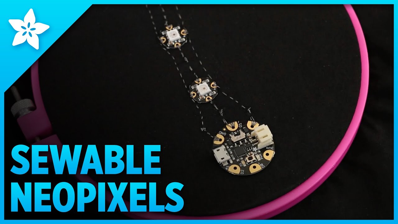
Becky Stern shows you how to sew a chain of NeoPixels using FLORA or GEMMA microcontroller to make your own wearable electronics projects. Full guide: https://learn.adafruit.com/flora-rgb-smart-pixels/
Visit the Adafruit shop online - http://www.adafruit.com
Subscribe to Adafruit on YouTube: http://adaf...
In this tutorial it talks about upgrading to silicone coated wire
Are there any tutorials on how to use the silicone coated wire with neopixels?
stark storm
You use it like any other wire, it's just more flexible
fluid cypress
Note that it is lots more flexible. You can't bend it into shape and expect it to stay there like with PVC wire
light wigeon
stark storm
You use it like any other wire, it's just more flexible
yes. what was a looking for was something to build off what was already there for conductive thread.
so something matching up wire gauge with number of neopixels and recommendations on needle types and needle sizes
the math itself isn't hard, but it would be good to build on the tutorial for the novice user who doesn't know what is the right question to ask.
wire gauge, current rating, and power draw of a neo pixel.
 unkempt marten
How about conductive nylon, is there a 'gauge' or similar consideration when using conductive nylon?
Also this stuff is pretty flexible, yeah?; could be bent 100,000 times without issue, probably? Intending to use this with a Q1 project.
"First of all it doesn't crack when bent or twisted! So you can make all sorts of odd shapes and paths without worrying about broken traces. It's also more flexible so you can put it on a flexible material."
"It's high conductivity, only a few ohms per foot. ..."
^^ I suppose these are the important points?
Any anecdotal experience or gotchas?

With our fun assortment of conductive materials, cosplay and wearables have never been easier to craft! This Conductive Nylon tape goes great with our ...
unkempt marten
Can anyone recommend a 'Squishy Switch'?
I want to hide a switch between fabrics, and then squish once to power on, and squish once again to power off.
Closest I found is this:
https://www.adafruit.com/product/4891
But, I'd like the surface-area-squish of a quarter/the size of a CR2032
Any recommendations?
 left urchin
What kind of fabric are you using?
left urchin
unkempt marten
Can anyone recommend a 'Squishy Switch'?
I want to hide a switch between fabric...
Thinking slightly outside the box, what if you used an NFC bracelet like https://www.adafruit.com/product/4043 and then had an NFC breakout or similar in the garment? You could trigger it that way.

This is a blank 13.56MHz RFID/NFC Bracelet with an NTAG203 chip - often used for train/bus passes, information sharing, contactless payment, but also found in other ...
you could then tap the area with the bracelet and fire off events that way
you might be able to use this too: https://www.adafruit.com/product/4762
With our fun assortment of conductive materials, cosplay and wearables have never been easier to craft! These Conductive Nylon Squares go great with our other ...
there's also the velostat stuff:
https://www.adafruit.com/product/1361

This conductive material (also known as "Velostat" or "Linqstat") is a nice addition for your wearable/sensor hacking toolkit. It's pressure-sensitive: squeezing it ...
hopefully some of that helped
unkempt marten
Awesome, thanks Torgny.
I've got a bunch of RFID stuff in my wishlist too, to maybe help out my HOA neighborhood --- security company wants $75 to replace lost RFID tags to the clubhouse/pool/gym..... and for ~$100 shipped, we can have the hardware ourselves to flash new/lost RFIDs as much as we want: and as long as we get the Current RFID code, before the tag is lost, then we can make replicas for super cheap, and in a much 'less' loseable format, like the RFID bracelet above =3
With an RFID shirt-button, https://www.adafruit.com/product/4429
if I put major (for me) effort into it, possibly, I could get the NFC/RFID in my phone to turn a jacket or garment on. Hide all the power and wires and all that away or in plain sight.
I love the idea of zipper switches too; at ~56 seconds:
https://www.adafruit.com/product/640
I might roll with a zipper switch, so when fully zipped-up, it closes the circuit & powers the device, and if I don't want the wearable powered, I can just unzip a tiny bit.
Totally forgot I wanted to do that
left urchin
that's neat, yeah, I saw the bracelet and was like... wow, that could be neat
I mean, you could even have one bracelet on either arm and trigger different things depending on which arm you're using... probably a super cosplay edge case, but still 😄
pure echo
unkempt marten
Can anyone recommend a 'Squishy Switch'?
I want to hide a switch between fabric...
Adafruit 3101 is the first thing that came to mind, but not exactly the most suited to a wearable. You might be better off DIYing a switch with foil contacts, like https://www.instructables.com/Use-a-DIY-Pressure-Plate-Switch-to-Automate-Your-H/ but scaled down to size…

Instructables
Use a DIY Pressure Plate Switch to Automate Your Haunted House: When running a large haunted house, you want most of the special effects to be automated. But for this to be effective, you need to get the timing right. The best way to do this is to use sensors to detect where your guests are. In this pr…
Bonus if you have a 3d printer compatible with TPU.
stark storm
light wigeon
wire gauge, current rating, and power draw of a neo pixel.
A NeoPixel draws about 60mA at full power.
summer gale
Good Morning and Happy Saturday! Question: If I wanted to fit a BLE + one RGB LED + a Vibrating Motor + Rechargeable battery in a ring (Just like Ringly did but not as many fancy options: I just want to adjust the RGB color and brightness via a BLE) which parts should I buy from the adafruit shop?
rapid radish
summer gale
Good Morning and Happy Saturday! Question: If I wanted to fit a BLE + one RGB LE...
For a form factor that small, generally you would be looking at making a custom PCB, etc. The off-the-shelf parts from Adafruit will generally be too large since they're intended for friendly breadboarding use.
summer gale
rapid radish
For a form factor that small, generally you would be looking at making a custom ...
I see, thank you.
 main lion
I've been trying to create some neopixel earrings I have been trying to use ItsyBitsy M0 but the size & shape are a bit large. So I'm wondering if the QT PY M0 without the extra Memory chip will work as well and if the itsy Bitsy M0 also will the ItsyBitsy Power BackPack (for charging & using a lipo batery) can be wired up to the QT PY M0
 amber widget
main lion
I've been trying to create some neopixel earrings I have been trying to use Itsy...
amber widget
main lion
I've been trying to create some neopixel earrings I have been trying to use Itsy...
You're going to have more constraints using the QT Py M0. What programming language are you using? I'm uncertain about the backpack.
fluid cypress
rp2040 QT py would alleviate some of those constraints.
stark storm
main lion
I've been trying to create some neopixel earrings I have been trying to use Itsy...
The Trinket M0 is another possibility, it's even smaller than an Itsy.
main lion
amber widget
You're going to have more constraints using the QT Py M0. What programming langu...
I'm using Circuit Python what other constraints the only issues being memory and power issues @stark storm I chose against the Trinket because the lipo charger product page said that it was only one one of the trinket boards from memory that is the Pro trinket - not CP compatible
stark storm
I've run CP on a Trinket, but it may well have been an old version of CP. Alas, there's no room on a Trinket for an additional memory chip
The product page does mention CP. Note that the older AVR Trinkets can't run CP, the M0 can, but it has limits on what will fit.

The Adafruit Trinket M0 may be small, but do not be fooled by its size! It's a tiny microcontroller board, built around the Atmel ATSAMD21, a little chip with a lot of power. We ...
long mango
stark storm
I've run CP on a Trinket, but it may well have been an old version of CP. Alas,...

This is a Trinket M0 that has been had a SPI flashchip bodged on by Dave Astels. It is not available for purchase.It was documented as a DIY project here.
I would not recommend this; easier to buy a new board that has more flash
amber widget
main lion
I'm using Circuit Python what other constraints the only issues being memory and...
There are beefier QT Pys, but I don't know about battery powering them. There is the QT Py RP2040 and the QT Py ESP32-S2 (which is new enough that it's out of stock at the moment, I am fairly certain.) I really feel like you will run into frustration trying to use CP on the QT Py M0 for much more than basic things.
 terse moon
amber widget
There are beefier QT Pys, but I don't know about battery powering them. There is...
terse moon
amber widget
There are beefier QT Pys, but I don't know about battery powering them. There is...
There is a battery BFF coming so at least that will be a great option 🙂
amber widget
terse moon
There is a battery BFF coming so at least that will be a great option 🙂
Good to know!
 upbeat wing
I am working on a tutorial for my latest wearable (pi zero 2) project. I have the hardware part done, now I am doing a fresh install so i can make the step by step tutorial and provide a disk image.
http://mrdcreations.org/
PiGlass v2
this is my ui
https://www.youtube.com/watch?v=ewayV9def0Y

it may end up being in march issue of magpi
upbeat wing
It will be a project showcase in March issue. I am very excited as this project is one of the coolest things I've ever made and at the same time it's easy to build, except for getting a pi zero 2. I timed myself making the 2nd one. counting soldering the pi header, the hardware took me 20 minutes to assemble, with just a soldering iron, heat gun and small flathead. My goal is to end up with a few people that want to make one. I'm thinking of offering a pi zero 2 to the first person who can show me that they have the other parts or ordered them, then I would send them pi zero 2 and a copy of my SD card.
light wigeon
i'm working on my own version for the firewalker shoes. but i'm using a 3 axis accelerometer instead of a pressure sensor. located in the middle of the shoe to get the orientation.
this works great for the most part. but i want it to do effects step down. I'm thinking about using the Z accel for that... negative Gs = lifting the foot up, positive Gs putting the foot down.
would that work?
rapid radish
light wigeon
would that work?
Yes, it should, though remember that the Z acceleration will also read gravity, so you might have something like 9.8 standing still, 11.0 lifting, and 8.6 falling, etc.
light wigeon
so both shoes have essentially an idle animation for when i'm just standing still
i want these shoes to wireless sync with each other to coordinate the animation.
as bending down to press a button on both shoes at the same time will be awkward.
and prone to drifting out of sync
any ideas on how to accomplish this?
rapid radish
light wigeon
any ideas on how to accomplish this?
Do they have any communications now, or are you asking how to add something wireless at all?
light wigeon
i would have to add something as i'm currently using stemma qt py
so i'm asking for recommendations on what to add... and how to implement it correctly.
rapid radish
One thing that comes to mind, since you have an accelerometer, is to do some sort of "click your heels together three times" pattern to establish a time sync.
light wigeon
yeah. i just wouldn't want it confuse normal movement with attempting to resync
the other thing i was thinking was having a floor mat with magnets and magnetometers... but i think that would break on an escalator
i'm not sure something i'd have to try
rapid radish
Jumping in the air might be another good signal to recognize, as the zero-g is easy to spot, and landing would generally be a solid sync time.
light wigeon
thats an good idea
if i did a bluetooth module
could i just have them connect to each other?
rapid radish
Yep. You'd generally just pick one to arbitrarily be the master node, I think.
rapid radish
There's also stuff like the nRF24L01 modules. Those have some pretty simple example code for basic sending and receiving of data.
light wigeon
what about: https://www.adafruit.com/product/3178
This is the Adafruit Feather M0 RFM95 LoRa Radio (900MHz). We call these RadioFruits, our take on an microcontroller with a "Long Range (LoRa)" packet radio transceiver with built ...
it would be a bit of waste of the long range ness
 cloud mantle
@light wigeon those shoes look awesome already! I got some firewalkers im starting soon (once my leds arrive) they are so fun
could you have the shoes talk to each other with ir sensors? radios seems like overkill to me
light wigeon
yeah i might stick with radio and get the rest of the fursuit i'm build to work in sync.
 magic bridge
what do you guys think of a pair of "vr goggles" but in the size and form of something like swimming goggles? It would be easy to put on and off and has built in tension/flex. It also fits around the eyes well and could be used in tighter spaces where you would normally bump into objects. I dont know if putting the electronics and lens in there would be practical though
 fluid cypress
magic bridge
what do you guys think of a pair of "vr goggles" but in the size and form of som...
fluid cypress
magic bridge
what do you guys think of a pair of "vr goggles" but in the size and form of som...
You've hit on the big issue: the electronics. If the big VR houses could make decent goggles with that low of a profile, they would.
I like the idea but the execution is probably 10+ years off.
rapid radish
The space for the optics is also an issue. Lenses like to have a little bit of distance for their local length. The Vive Flow is about the best commercial product in terms of compact VR headset, and that's significantly larger than swim goggles.
upbeat wing
to give you an idea of what can currently be done with the swimming googles form factor and even still its bulkier than plain googles. it's only capable of displaying text and basic graphics.
https://www.formswim.com/

FORM
Instructions and real-time metrics motivate you through your workout with zero distractions. All you have to do is show up and swim. Transparent in-goggle smart display. Real-time performance metrics like distance, time, and pace. Swim workouts with in-goggle instructions.
cloud mantle
light wigeon
yeah i might stick with radio and get the rest of the fursuit i'm build to work ...
that makes sense! mine are going to be part of a costume too but Im just going to network all of the micros with 12C probably
i do want to make a remote control (for handler to use) with lora radio though
I love big costume projects 💜
@magic bridge have you seen this? is a video about glasses displays

You can make a HUD with a transparent OLED - if you want it to suck.
The first 1,000 people to use this link will get a 1 month free trial of Skillshare: https://skl.sh/zackfreedman06211
I get asked a LOT to use a TOLED, a crystal-clear display, to make a cheap wearable heads-up display project based on the Tenex volumetric display. So I did! T...
that's why the displays use prisms
pure echo
fluid cypress
You've hit on the big issue: the electronics. If the big VR houses could make de...
@magic bridge There are many ways around electronics, and it's not quite as large as they once were. Think wearable side-packs, Pi Zero on headband, etc. Optics, on the other hand, is definitely a space issue. They definitely have made strides in shrinking them, but the small waveguide systems are also prohibitively expensive still. Until plastic waveguides are ready for mass-production, we're a long way from super-portable, prism-less, personal VR/AR.
 lofty lily
What are the most compact (and not absurdly expensive) batteries to put on a wearable?
Currently using an Artemis Nano w/ a charging rate of 500mah so I have to work within that constraints while using the smallest battery possible
Unless its a good idea to de solder the charging pieces and solder on my own since that should work
left urchin
lofty lily
What are the most compact (and not absurdly expensive) batteries to put on a wea...
have you measured how many amps your device consumes per hour?
lofty lily
left urchin
have you measured how many amps your device consumes per hour?
~10-15mah depending on load
left urchin
that is constant, no sleep?
left urchin
OK. Gloves. Hmm. So Something flat that you can put on top of your hand, maybe?
lofty lily
left urchin
OK. Gloves. Hmm. So Something flat that you can put on top of your hand, maybe?
Yeah, tiny pcb (like 40x20mm)
 left urchin

Lithium-ion polymer (also known as 'lipo' or 'lipoly') batteries are thin, light, and powerful. The output ranges from 4.2V when completely charged to 3.7V. This battery has ...
they're cheap, work great...
lofty lily
Wow that is actually really nice, been struggling to find the proper lipos
Since whenever I look them up I just find ones with weird dimensions
left urchin
so the 400s are all chunky and dumb (unless you're pairing them with a feather and you don't have a height restriction, basically)
lofty lily
Yeah I don't have a height restriction; it's just that I need to make it as flat as possible
left urchin
Only reason I know is because I ordered like pretty much every battery type
lofty lily
Like I was originally considered ultra thin lipos but those are annoying to obtain
left urchin
that 500 mAh battery is nice
lofty lily
And also I gotta de solder stuff
Yeah having 500mah is really nice
Could run this thing for a few days without issue
left urchin
you got any feathers?
lofty lily
Nope, just development kits and then nano sized stuff
lofty lily
Like an Arduino Nano size
left urchin
they're 45 mm x 18 mm... ok... so a feather is 51 mm x 23 mm, so pretty much the same
left urchin
lofty lily
Like an Arduino Nano size


There you go. Hopefully that helps illustrate the size.
lofty lily
Yeah
lofty lily
left urchin
Yeah, just opened the sparkfun brd in eagle (I have little idea how to use eagle so I am just using measure tool for this) but its 43x20mm or so
And it's wireless, so the battery can't go above 40mm in length since the antenna would get screwed with, and the battery you linked would work but its like 10mm wider than the board so it would be a bit weird
But unless you have a battery that fits more into the dimensions I guess this will do
left urchin
the 400 mAh is like half as wide, but, it's a chonker at basically double the thickness
lofty lily
Yeah
Would a 400mah even work with the artemis, it has a charging rate of 500mah and is highly recommended to use 500mah minimum according to the website
Oh yeah, a lot of these batteries have built in protection in them, would this protection protect the battery from having issues if someone were to put it onto the 500mah artemis lipo charger?
left urchin
I would think so. But, let's wait for someone with actual technical expertise to chime in.
oh wait, that's a Sparkfun board? You are going to have to check the polarity of the Adafruit battery because they might be reversed
stark storm
lofty lily
Oh yeah, a lot of these batteries have built in protection in them, would this p...
It's a 500mA charger, not a 500mAh charger. And that might be a bit much for a 400mAh battery (most of these flat LiPo cells don't want to be charged at more than a 1C rate). However, if you're okay with soldering, you can change the charge rate by swapping the programming resistor on the charge chip.
 vapid gorge
lofty lily
Oh yeah, a lot of these batteries have built in protection in them, would this p...
vapid gorge
lofty lily
Oh yeah, a lot of these batteries have built in protection in them, would this p...
If you can remember to always remove the battery before plugging the usb cable in the artemis, you could charge the smaller battery with a separate charger (the Adafruit ones have a default charge rate of 100mA)
rapid radish
lofty lily
Like I was originally considered ultra thin lipos but those are annoying to obta...
I've used this shop before as a source for different shapes of lithium batteries: https://www.powerstream.com/li-pol.htm
World's largest selection of stocked Lithium Polymer Batteries for engineering, experimenting, and repair, LiPo battery sizes, specifications and data sheets
long mango
be very careful with the polarity on LiPo's. We have seen third-party batteries that use the same connector as what Adafruit uses, but the polarity is reversed.
lofty lily
long mango
be very careful with the polarity on LiPo's. We have seen third-party batteries ...
Yeah, I've heard of that happening, where a lot of people complain about the polarity being reversed, in my case I am going to be removing the jst and putting the battery in properly no matter what (saves space)
lofty lily
stark storm
It's a 500mA charger, not a 500mAh charger. And that might be a bit much for a ...
So I assume CHG is the programming resistor, what would I need to swap it to to charge a smaller battery?

I mean what resistance would be used for smaller batteries
vapid gorge
lofty lily
I mean what resistance would be used for smaller batteries
SparkFun have a table of resistor values for different charge rates in their guide: https://learn.sparkfun.com/tutorials/lipo-charger-plus-hookup-guide#hardware-overview
lofty lily
Oh cool
lofty lily
vapid gorge
SparkFun have a table of resistor values for different charge rates in their gui...
Is there supposed to be a calculator in here or something it says invalid equation

Also, lets say I am using a 110mah or 40mah lipo, what would I do then
rapid radish
lofty lily
Is there supposed to be a calculator in here or something it says invalid equati...
It looks like the mathematical equation has an invalid syntax or something. It's just RPROG(kOhm) = 1000V / IREG(mA). So if you want 110mA of current, it would be 1000 / 110 = 9.09kOhm.
long mango
Feathers tend to use a 100mA charge setting
lofty lily
ok, cool
rapid radish
Note that the mAh capacity of a battery is not perfectly related to what charging current it wants... some may prefer to charge faster or slower than the base "1C" rate. The battery datasheet will generally specify that.
rapid radish
Yep, maximum 1C, though "standard" charging is only 0.2C.
lofty lily
Is there a downside to using the max charging
rapid radish
Maybe some degradation over the course of its lifetime, like fewer charge cycles before it finally dies. I expect they picked the standard charging to be a bit conservative to extend the lifetime as much as they could. If you don't care about fast charging, you might split the difference at 0.5C or something, but I also don't expect 1C will cause any real issues.
rapid radish
It puffs up and won't hold much charge any more, yeah.
lofty lily
How many charge cycles is expected
rapid radish
Usually about 500.
pure echo
It’s also dependent on a whole slew of variables regarding the use and environment of the battery.
amber widget
That seems low. Not as in I-know-better-than-you, but as in, a tiny lipo runs out relatively quickly on some projects and 500 seems like something that would be reached quickly.
Good to know.
rapid radish
Looks like this particular cell is rated for 300 cycles until it drops to 80% capacity.
lofty lily
How many cycles is it until the battery is a paperweight
Actually, how do companies that make products make it so their batteries last the longest?
rapid radish
As Hem says, it's highly variable, and can matter whether you do a full discharge of the battery, or are constantly recharging it from a slightly-discharged state, etc. The general order of magnitude of lithium chemistry is around that 500-1000 sort of range, but all sorts of details about the electrode structure can influence it.
stark storm
lofty lily
So I assume CHG is the programming resistor, what would I need to swap it to to ...
I think the component marked "CHG" is an LED, I'm not sure which resistor is the charge current programming one. Note that most chargers charge to 4.2V which is the way to get the maximum charge into a cell, but reduces cell life. There are chargers available that only charge to 3.9V or so, which lead to less capacity but much longer life.
lofty lily
stark storm
I think the component marked "CHG" is an LED, I'm not sure which resistor is the...
Yeah that turned out to be a LED
The 500mah lipo just came in the mail
A bit too big, gonna go for the 150mah by adafruit since that would fit the width and length
So now I just need to figure out what resistor I need to replace

I guess it's the two near the charging chip
But don't know which one
Anyone happen to know?
rapid radish
lofty lily
Anyone happen to know?
The tan components are typically capacitors. You want one of the black passives with numbers on them instead. From the schematic, the charge-current resistor is a 2k, and it should be the only one on the board, so you'd likely be looking for a "202" marking. The photos are too low-res for me to identify it here, but hopefully you can spot it on the real board.
stark storm
Otherwise, you may need to download the build files to identify it.
lofty lily
rapid radish
The tan components are typically capacitors. You want one of the black passives ...
Yeah I was able to identify the 2k resistor and will replace it with a 12k one
I looked onto the eagle thing and looked on the components list
its the resistor right above the module

I now have a 0603 12K resistor and am gonna de solder the old one and replace it with a new one
Never de soldered and soldered 0603 resistors before
Any guidelines?
All I know is to head up the resistor ends, quickly pull it up with tweezers and then heat it up again and place the new one in and apply some solder w/ flux in it to it
Do I need to do anything else aside from that
 pastel basalt
If I wanted to 3D print necklaces, install neopixels into the prints, run them with code using an Adafruit library & an Adafruit PCB board like a gemma, then sell them to people, what is the legality of reselling my 'product'? What if I just put Adafruit example code onto a single ATtiny85 or something? If I were to sell that, would I need permission from the library creator? I'd appreciate any answers anyone may have!
stark storm
lofty lily
Any guidelines?
If you can heat both ends at once, it'll come right off. However, if you can't, the easiest (and safest) way forward is often to just cut the resistor in two and remove each end separately.
 misty roost
Hi I'm trying to add some lights to my watch using some neopixels but all I can fit in the space I have is a gemma and a cr2032 which is a non rechargable 3v coin cell battery. Can I run 15 Neopixels off of 3v if so how long will they last at 75% brightness.
rapid radish
misty roost
Hi I'm trying to add some lights to my watch using some neopixels but all I can ...
That's likely going to be problematic both because of the voltage (Neopixels prefer 5V though can run a little lower) and because of the current (60mA each at maximum brightness, so 15 of them at 75% would be like 0.7A, way more than a coin cell can handle).
misty roost
Ok thank you for your help so much
lofty lily
I am trying to get a fuel gauge for my Sparkfun Artemis Nano since I am making a custom breakout board for it
But none of them seem to be in stock
Anyone know any fuel gauge chips that aren't oos everywhere?
Like so far I have looked at the MAX17043 but those are all OOS
The chip doesn't have to be too accurate as long as it can generally measure the power thats left in my 150ma lipo battery
rapid radish
lofty lily
I am trying to get a fuel gauge for my Sparkfun Artemis Nano since I am making a...
Check Mouser... they seem to have a number of the MAX17xxx series in stock, so you might be able to find a similar part to that one. Also TI seems to have some stock on their own site. Most of their parts are DSBGA, unfortunately, but the BQ27410-G1 is more of a regular package and is available.
lofty lily
rapid radish
Check Mouser... they seem to have a number of the MAX17xxx series in stock, so y...
Yeah, that's what meant by them not having anything useful, the majority of them are DSBGA or super expensive and do a lot of stuff I don't really need
Like a lot of the MAX170 modules are like 1.5-2$
lofty lily
rapid radish
Check Mouser... they seem to have a number of the MAX17xxx series in stock, so y...
My main issue is the BQ27410-G1 is like 10$ compared to being like 2$ for a MAX170, and price is a big factor in my project
rapid radish
lofty lily
My main issue is the BQ27410-G1 is like 10$ compared to being like 2$ for a MAX1...
You might consider omitting a dedicated fuel gauge chip and just using a simple resistor divider voltage measurement. That won't be very precise, but it would be enough to sound a low-battery warning.
lofty lily
rapid radish
You might consider omitting a dedicated fuel gauge chip and just using a simple ...
Would it be good enough to tell like if its about 100% power, about 75% power, 50%, 25%, ect
rapid radish
Yes, I expect so, especially if your power draw is relatively constant.
lofty lily
Yeah
rapid radish
You could also keep track of total run time to help the estimate.
lofty lily
Yeah that was what I was originally thinking was having the user charge the battery to max and then have the arduino save the estimated battery level
I don't think the Artemis Nano can tell if it's charging though aside from the one LED on it that says it is charging
Also, would a current monitor such as the INA219 work better than the resistor divider? Since from what I am seeing it is able to measure voltage which is close enough to being able to measure the remaining power
rapid radish
If you wanted to, you could use a current monitor to implement your own fuel-gauge algorithm.
It probably wouldn't do much of a better job in just measuring voltage, though.
lofty lily
So its simpler to just do the voltage divider then
rapid radish
Yup, assuming that the Nano has an ADC on it.
lofty lily
Yeah
It's got like six of them on it since it's a board for their Artemis module
Which is just a suped up NRF module it seems with preloaded arduino support
And I am going to be putting in an analog multiplexer for the extension board I am making for it
lofty lily
rapid radish
Yup, assuming that the Nano has an ADC on it.
Pretty much gonna have a tiny extension board that's generally in this C shape with all the features I wanna implement that the board does not have by default and I will de solder stuff like the QWIIC for more space if needed

And the multiplexer is gonna be as far away from the wireless module as possible
(About 35-40mm away from the antenna)
And this will give space for the leds so I can put this into a 3D printed enclosure and have led holes
Actually that raises a question how does this board deal with analog interference?
There's six analog pins and four of them are pretty close to the module
Wouldn't that cause issues
rapid radish
Generally the radio frequencies will be well out of range of the ADC's sensitivity.
lofty lily
With a multiplexer then would I need to worry about interference then still or nah
rapid radish
The main effect would just be having metal of any sort near the antenna, independent of its circuit function. So no worries if your daughterboard is on the other side from the radio module.
lofty lily
Ok cool
Also one sec I have something that I was wondering but didn't know how to ask it in a way that google would give me a useful answer

On the bottom right there is a lipo connector
Am I able to de solder it and solder the lipo directly without issues
The hole doesn't have the lining if the connector is removed from what it looks like

Also, is it possible for a daughterboard to control whether or not an arduino is powered on/off assuming I can't remove the lipo connector and add a wire going to the daughterboard in which the lipo would connect to? Or would the best that I could do is have the daughterboard have a switch that tells the arduino to go into sleep
rapid radish
It looks like the battery connector is a surface-mount part on only the top side of the board, so those +/- holes on the bottom are extra connections you can use for soldering battery wires to directly, I believe.
lofty lily
Wait so if I de-solder the connector it won't remove those holes? Awesome!
So at that point I could de-solder it, have the lipo connect via the daughterboard and then go downwards to the main pcb
And have a on/off switch to cut off the lipo when needed?
Epic
rapid radish
Also, the PSWC pins seem to be hooked to the power regulator's enable signal, so if you pull that to ground, it will disable the processor while still allowing battery charging.
They put the holes there so you can solder on a power switch if you want.
lofty lily
rapid radish
Also, the PSWC pins seem to be hooked to the power regulator's enable signal, so...
Oh so it has built in a pin meant for me to add a on/off switch, cool!
Oh yeah, how do I work out what temperature is acceptable for de soldering QWIIC and the lipo connector (SMD Components)? Using a soldering iron
rapid radish
Not sure there. Desoldering is often tougher than soldering.
lofty lily
Yeah, that's why I asked since I don't wanna cook my board
Tryna de solder a resistor, and two smd headers
And this board is really thin too
 azure garnet
newbie trying to make a usb rechargable amulet. im hoping to use a trinket m0 as the main board, will the trinket backpack work with that or is there an issue with the 5v situation. if not what can i get to allow the battery to connect to the board AND be chargable?
long mango
azure garnet
newbie trying to make a usb rechargable amulet. im hoping to use a trinket m0 as...
you might be able to use a Feather M0 basic and chop off the prototyping end of the board. I don't know if vital traces go through that area or not. Then you have one board with a charger. I am assuming the basic Feather shape is a little too long.
azure garnet
Feathers too big in genral, after reading the documentation on the trinket pro hat I don't see why it wouldn't work for what I'm trying to do and it is working as a lipo source so I think it's good
 graceful shore
HI
What would the experts here recommend - a student is currently using a Gemma M0 to control some Neopixels in a wearable project design, but wants to be able to control them via Bluetooth.
Also They are using MakeCode so i am not sure waht would be the best micro-controller to recommend to them as a replacement as it needs to be as similar in size as possible to the Gemma M0
Any suggestions gratefully received
Stay safe
long mango
graceful shore
HI
What would the experts here recommend - a student is currently using a Gemm...
https://learn.adafruit.com/adafruit-itsybitsy-nrf52840-express is tiny and has BLE, but I don't think MakeCode supports BLE on other than the micro:bit. It's quite possible in CircuitPython: we have many such projects: https://learn.adafruit.com/circuit-playground-bluefruit-neopixel-animation-and-color-remote-control, https://learn.adafruit.com/search?q=bluetooth%2520neopixel
graceful shore
long mango
<https://learn.adafruit.com/adafruit-itsybitsy-nrf52840-express> is tiny and has...
ThankYou Mr Halbert
Very kind of You to take the time to help me out!!
I will let the student know & hope to get a more full idea from them of exactly what they want to achieve - once i know that then hopefully will be able to come up with a solution for them.
Thanks Again!!
 median oracle
is it possible to wire a lipo recharger like the backpack through a QT PY? I want a single USB port on the device for programming as well as charging
vapid gorge
median oracle
is it possible to wire a lipo recharger like the backpack through a QT PY? I wan...
I'm interested in trying exactly this too, I'm just waiting for my Micro-Lipo Charger with USB C to arrive. According to this guide, it should be possible: https://learn.adafruit.com/adafruit-microlipo-and-minilipo-battery-chargers/pinouts
"The USB-C Micro-Lipo charger is special. We've exposed the data lines so you can use it both as a USB-C breakout and a Micro-Lipo charger."
amber widget
median oracle
is it possible to wire a lipo recharger like the backpack through a QT PY? I wan...
There's also an add-on of that nature specifically for the QT Py in the works, but there's no ETA on that, so don't wait on it. But I figured it was worth mentioning for future reference.
median oracle
vapid gorge
I'm interested in trying exactly this too, I'm just waiting for my Micro-Lipo Ch...
I just successfully wired a lipo trinket backpack to a Trinket M0, just curious if there's any reason it wouldn't work with a QT PY 2040. The wiring was done to GND, Batt and USB
 graceful dew
the qtpy doesnt have the extra diode so its not really recommended ... you'd have to connect a diode from batt to USB on the backpack
light wigeon
Hi, im new to adafruit and have a project to do for school. My idea is to make a glove that lights up one you hold things.

I was wondering can you force a force resistor as a input device to activate an LED
and how you would connect it to an adafruit playground express
Im using the Arduino IDE but it would be fine to go through with it in MakeCode
rapid radish
Generally you wouldn't directly hook the force resistor to the LEDs, but you'd have the Playground read the sensor via an analog input, and activate the LED based on that.
You may run out of pins on the Playground, though, if you need a sensor and a LED for each finger.
light wigeon
would one large one on the palm of the hand work?
rapid radish
Yep, you've got 8 pins to play with on the Express, so you can allocate them however you like between LEDs and sensors.
rapid radish
Couldn't comment there, I'm afraid... don't have any experience with MakeCode myself.
light wigeon
Np thank you so much
light wigeon
light wigeon
Hi, im new to adafruit and have a project to do for school. My idea is to make a...
Jacques Monestier
https://en.wikipedia.org/wiki/Le_Défenseur_du_Temps
YT videos
This one's less mysterious:
light wigeon
Thanks @light wigeon
ok i got the parts for my project
does anyone have an example of using a force sensor as an input device?
stark storm
Which force sensor? Some of them are pretty simple resistive ones, so you just build a voltage divider with it and a fixed resistor and connect the junction to an analog input.
light wigeon
.oO( awroo wearables of London .. awroo)
i took a pic of all my materials


I have 2 of the smaller ones and one big one
bought them from creatron inc in Toronto
I can only use conductive thread for this project
@stark storm would these ones work?
I am using them to activate NeoPixels
4 individual ones and a NeoPixel ring of 12
stark storm
Those are ordinary force sensitive resistors, there's a helpful page on how to use them here: https://learn.adafruit.com/force-sensitive-resistor-fsr
 light wigeon
Thank you @stark storm
light wigeon

Hi I wired the thread up with the force resistors

Any advice on the threading
It is stuck within the glove as my prof said no components can be exposed
And no regular wires can be used
lofty lily
What are alternatives to trimmer potentiometers? I was originally intending to use them to sense rotation but from what I keep seeing in datasheets they have incredibly low lifespans of ~200 turns

I want to be able to sense horizontal movement (very frequently) on a wearable
fluid cypress
encoders?
lofty lily
fluid cypress
encoders?
Wow these seem perfect, what's the lifespan and how short do the shafts get?
Cause I do see really low profile ones which would be perfect but none of the ones im seeing from google have lifespans
fluid cypress
I couldn't give you specifics for sure. It depends a lot on what you want to spend
every part has a lifespan
lofty lily
Well essentially I want to track the splay of a finger and toe
For a motion capture device
A potentiometer would be perfect for sensing rotations such as that but they are way too large to fit on a finger or part of a foot
Particularly Height-Wise
fluid cypress
that's a tough order
lofty lily
Velostat is something else I was considering using
But if the finger or toe moves downwards that from my understanding will screw with the sensor
fluid cypress
Yeah encoders generally track ONE degree of freedom
so to properly measure a toe's motion you'd need at least 3 measuring devices
per joint
lofty lily
Well I can sense up and down motion properly
But not with left and right movement (splay)
fluid cypress
Here's one source of small encoders (may not be small enough) https://www.dynapar.com/products_and_solutions/rotary-encoders/miniature/

Dynapar offers incremental and absolute miniature rotary encoders with diameters 2 inches and less for feedback applications in tight spaces.

 fluid cypress
here's a simple video https://www.youtube.com/watch?time_continue=2&v=v4BbSzJ-hz4&feature=emb_logo

https://howtomechatronics.com/tutorials/arduino/rotary-encoder-works-use-arduino/ ► Find more details, circuit schematics and source codes on my official website .
In this tutorial we will learn how rotary encoder works and how to use it with Arduino. A rotary encoder is a type of position sensor which is used for determining the angular positi...
lofty lily
fluid cypress
here's a simple video https://www.youtube.com/watch?time_continue=2&v=v4BbSzJ-hz...
Yeah, that's what I thought they'd do. They can sense rotation and direction horizontally, which would be perfect for my usecase
lofty lily
lofty lily
As long as I can find one with the shortest shaft possible or whatever version of rotary encoder this is it would be perfect
Cause I am gonna be using a 3D printed gear-type piece and going onto it like that would be amazing
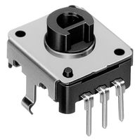
Octopart
Find the best pricing for ALPS EC12E2440301 by comparing bulk discounts from 9 distributors. Octopart is the world's source for EC12E2440301 availability, pricing, and technical specs and other electronic parts.
Was able to find the part for it finally
And it's not too expensive either, only 2$ a piece

How do I tell if a model has detents?
rapid radish
lofty lily
How do I tell if a model has detents?
The table on the first page of the datasheet says which part numbers don't have detents, but it looks like most of them do.
lofty lily
Yeah
That's what I just saw too is thats what the first page meant
Yeah all of the small ones have detent
Does less detent = more cycles?
Since some have 12 detent and some have 24
(The one with 12 detent is also very much in stock)
Ok yeah the lifespan will be ok nice
The lifespan is comparable if not better than the average cheap potentiometer
lofty lily
These rotary encoders only have three pins, what's the circuit I should be using for them?
https://media.discordapp.net/attachments/451155251580633089/946321419636195358/ALPS-EC12E2440301.png

Haven't seen a rotary encoder with 3 pins before
All the ones I see on google have like 5 pin output
Is it just the same wiring as a potentiometer?
Oh yeah, what are things I should do with empty space on a pcb?

I have 30 pins on the right
20 of them are going to a mux most likely
Depending on what the circuit is for the rotary encoders
Also, since presumably the ldo will get warm, what would be the best place to place it on the pcb?
Since I assume I shouldn't be placing it near the important stuff
Also, anywhere below this line can have components on the bottom layer

This is due to the battery not being able to overlap to that area
I decided to expand the pcb size since it was unnecessarily small and also by doing this it gives me more space to put different battery sizes in case of a battery shortage or needing a heftier battery than what I originally thought
pure echo
lofty lily
Haven't seen a rotary encoder with 3 pins before
Rotary encoders usually only need 3 pins. The 5 pin ones usually use two buttons for the push button momentary switch.
pure echo
lofty lily
Is it just the same wiring as a potentiometer?
It is not the same wiring as a potentiometer, as pots use a varying resistance to detect position. Rotary encoders, on the other hand, use two digital inputs instead of one analog input, and they detect position changes by those digital inputs. https://learn.adafruit.com/pro-trinket-rotary-encoder/example-rotary-encoder-volume-control is a nice, simple example of an encoder application, as it's just three wires: one ground, and two input_pullups.

Adafruit Learning System
Use Pro Trinket as a combination keyboard and mouse device
pure echo
lofty lily
Oh yeah, what are things I should do with empty space on a pcb?
Empty space can be utilized for ground pours and silkscreen, you don't have to fill every last nook and cranny if you don't need to. PCB questions should go to #help-with-hw-design as those guys are more specialized to answer those questions.
 dusk wharf
lofty lily
What are alternatives to trimmer potentiometers? I was originally intending to u...
dusk wharf
lofty lily
What are alternatives to trimmer potentiometers? I was originally intending to u...
You can also find potentiometer based rotary sensors, these have a higher resolution than a rotary encoder. This part from Bournes which I am using in a few projects has a rating of 1 million cycles, and is very thin: Bournes 3382H-1-103: https://www.digikey.com/en/products/detail/bourns-inc/3382H-1-103/2080233?s=N4IgTCBcDaIMxwBxgBIFoCMmAMcQF0BfIA. You can also research magnetic rotary encoders which can be tiny.
light wigeon
hi
i was wondering how to program a neopixel to be activated by an FSR


These were my attempts
pure echo
light wigeon
i was wondering how to program a neopixel to be activated by an FSR
Program has extra pixel sets, but otherwise has the right basic idea. How are you wiring up the FSR?
light wigeon
Using alligator wires at the moment
I will use conductive thread and fabric after i know the code works
The extra pixel is an extra neopixel
have 2 more + a ring
these 2 versions of my program dont really work very well
pure echo
Is your FSR wired via voltage divider?


 pure echo
Yup, just be careful to not short the two clip ends on the FSR.
light wigeon
ok so than the problem is in the code
pure echo
What's the resistance of the resistor? I can't quite make out the bands.
light wigeon

I think I have higher resistance resistors that I used last year
220 oms
for these
pure echo
Oh, that might make it hard to use the FSR. I definitely recommend a higher value.
light wigeon
ok i have 20k resistors
pure echo
I think most FSRs go down to around 200 Ohms if you press REALLY hard on it. Try the 20k.
light wigeon
ok
pure echo
The higher the value, the more sensitive your FSR will be. Since the range for your typical FSR is 200-100000 ohms, the general recommendation is 10k, but realistically anything between 1k and 20k should work fairly well.
light wigeon
works but in reverse but the leds are changing color
pure echo
Great! If you want to reverse it, you can either switch the 3v3 and GND connections, or invert the logic in your code.
light wigeon
thanks so much
is there anyway to take a way the gitterness of the leds
Would setting a brightness work?
pure echo
Which code are you running?
If it's the first one, just take out the set leds to black at the start of the forever loop.
light wigeon
ok that is the one I was running
pure echo
You should also be able to move the pixel and fsr definitions above the loop, so it doesn't redefine it every iteration.
Setting a brightness is optional, and I'm not familiar enough with makecode to know how to do it, but it wouldn't affect the blinking.
light wigeon
Would 2 strips of conductive thread be able to connect a force resistor?
misty roost
I'm having a problem running neopixels off of 2*cr2025 they have this weird flashing however when running of a power supply they never have this problem power draw is about .01 amp
pure echo
A button battery typically doesn't deliver enough current to drive a Neopixel, even if the voltage is sufficient. They're typically used for microamp applications like RTC, though people have had some success with blinking single-color LEDs. If you try to draw more than a milliamp or something continuously (sorry, I don't know the exact limits) your voltage will start to drop very quickly.
@misty roost If at all possible, I'd advise a small lipo instead of coin cells for a NeoPixel.
misty roost
I see
However even when dropping the voltage on the power supply it dims before blue goes then green and then a few dim red before going deqd
there is never any flashing
 ancient dune
A wearable I’m using uses a CR2032 for a few small LEDs
pure echo
misty roost
there is never any flashing
Button cells might be able to provide higher current in pulses, which could explain your blinking behavior. Regardless, continuous 10mA is a lot for a coin cell, and definitely not something coin cells are typically used for.
ancient dune
Little lithium button cell
stark storm
misty roost
I'm having a problem running neopixels off of 2*cr2025 they have this weird flas...
That supply is a little marginal, but you could try adding a capacitor to smooth out the current pulses
misty roost
stark storm
That supply is a little marginal, but you could try adding a capacitor to smooth...
What capacity?
stark storm
misty roost
What capacity?
It's not critical. 470µF or 1000µF are popular values, but whatever you have on hand is worth a try.
misty roost
Ok Thx so much
 nimble pine
Hi, does anyone know if there is any adafruit feather for the nrf5340 or any equivalent small form factor boards which could be used for AoA direction finding?
long mango
nimble pine
Hi, does anyone know if there is any adafruit feather for the nrf5340 or any equ...
We don't support the nRF5340 yet. It uses zephyr instead of a SoftDevice, so porting to it is going to be a lot of work.
we don't have short term plans to port to it
 idle crown
I have a adafruit liPoly usb charger. Both the red and green lights now come on when plugged in.. Does this mean it is toast and I let the blue smoke out??
just ordered a new one plus usbc charger but want to know if i can scrap this one I have
stark storm
I think the green light is power and the red light is charging? If no cell is attached, I think the red light comes on too
idle crown
Both are on when I plug it in and when a battery is attached. I think it is broken. Don't know what happened. Got two new ones on the way from adafruit.
Açcording to docs red charging green charged
idle crown
But both not on at the same time
vapid gorge
idle crown
But both not on at the same time
"Charge Indictator LEDs
There are two LEDs on each MicroLipo charger.
Red - this means the chip has detected a cell and is charging it
Green - this means the chip has completed the charge cycle and the battery is ready to go
Both - this means the battery is damaged or isn't plugged in."
https://learn.adafruit.com/adafruit-microlipo-and-minilipo-battery-chargers/plugging-in
You probably need a new battery, not a new charger 🙂 Check the battery wires and voltage?
idle crown
Have multiple batteries that are good have a charge.. but when I plug them in. Still two LEDs..
Not that charger it is the microlipo the one that does not need a cable
It is this one V1

Oh so adorable, this is the tiniest little lipo charger, so handy you can keep it any project box! Its also easy to use. Simply plug in the gold plated contacts into any USB port and a ...
The charger is really old (at least 5 years ago) .. Will test everything when I get the new chargers.,..
hmmm checked the voltage on the battery side with it plugged intot he charger it is 4.14 V which looks right for charging but both leds are on? Not sure if this is broken or not???
From the description:
There are two LEDs - one red and one green. While charging, the red LED is lit. When the battery is fully charged and ready for use, the green LED turns on. Seriously, it could not get more easy.
Got my new chargers and it is the old charger is toast. The new chargers shows one battery as charging (red led) and the other as full (green led). I am draining one battery to make sure it can charge.
misty roost
Long story short I broke the on & off switch on a gemma m0 from an old project and need to reassemble it withen a day or two so ordering is out of the question and the pieces are gone as well so which pins should I solder together to permanently turn it on
stark storm
misty roost
Long story short I broke the on & off switch on a gemma m0 from an old project a...
The two pads on either side of the "On" silkscreen.
misty roost
top and bottom of it
stark storm
misty roost
top and bottom of it
Huh?
light wigeon
Could anyone help me with ST25DV16K NFC tag? in the beginning it all works fine as I tried to write information like url and text with an NFC app on my iphone, but then at some point the NFC stops working and the app says the tag is not supported, So I guess i made it corrupted somehow, is there anyway to fix it?
lofty lily
For a compact pcb for a wearable, how do I secure it in a 3D printed enclosure?
It's 15x30mm so its really small
Most screw holes don't fit it, with common ones from my understanding being m2.5 and m3
rapid radish
Yeah, that's tiny. Maybe just glue or hot glue to the enclosure wall?
lofty lily
Ok, thought so
Just making sure
Would it be a good idea to put in a hole instead for a 3D printed plastic insert?
Like for a 3D guide printed rail to go into
Cause I have a lot of free real estate on my pcb now that the pad holes for it are properly sized
stark storm
lofty lily
For a compact pcb for a wearable, how do I secure it in a 3D printed enclosure?
Sometimes I'll make a groove in the enclosure and slide the board into that
 naive wagon
Is this the right channel for lilygo twatch?
I'm looking to program a watch with a moon phase calandar
Not moon phase . But it will tell me if moon is in Leo . Or moon is in Libra. I think this is one of the best uses but can't find anything like it
stark storm
naive wagon
Not moon phase . But it will tell me if moon is in Leo . Or moon is in Libra. I ...
Shouldn't be too hard to code up.
 pine heart
Hi, I have a flora JST 3 pin connector, and is there any trick to unplugging the connection? I'm putting in a significant amount of force but I don't want it to break.
 proud lynx
Does anyone know if a 3.7V LiPo battery can supply enough power for a 5V RGB LED strip? I know it's under voltage I'm just working with limited resources now
stark storm
proud lynx
Does anyone know if a 3.7V LiPo battery can supply enough power for a 5V RGB LED...
It depends somewhat if you mean an analog RGB strip or an addressable one, but the short answer is both will basically work.
proud lynx
An addressable one, but sweet!
stark storm
A bonus to running the addressable ones from lower voltage is you don't need a level shifter to drive the data input from 3.3V logic.
pine heart
What part is the latch/clip?

I ended up removing it for now by using my tweezers like a lever but I suspect this might not be the right way

 hollow oxide
if anyone has any experience with the monster m4sk, is there way to duplicate all arcada.display functions to both arcada.display and arcada.display2? i basically want both eyes to do the same thing with the project im working on.
hollow oxide
found the mask_arcadatest example. looks like you have to duplicate everythign to the second display yourself. okay then!
 compact pebble
I’d like to have a flexible bright programmable LED panel that is approx 21” x “14” rectangle. Ideally I’d like it with an app or an easy way to program any pattern that I want
Any tips on where I can find this?
pure echo
compact pebble
I’d like to have a flexible bright programmable LED panel that is approx 21” x “...
21"x14" is a fairly large dimension for an LED matrix. You may have to put 3-6 matrices together with their own controllers...
You might have some luck finding the matrices for cheap on AliExpress, but finding them with an app or a programmable controller might be a bit tougher?
stark storm
compact pebble
I’d like to have a flexible bright programmable LED panel that is approx 21” x “...
That's what this was for: https://www.adafruit.com/product/1453 There are some modern FPGA boards that can drive such things.

Ever looked at a wall in your apartment and thought "hey this could really use some art, or maybe an eye-blistering LED wall"? We do every single day! Then we finally did something ...
There's an article on Hackaday on the FPGA boards: https://hackaday.com/2020/01/24/new-part-day-led-driver-is-fpga-dev-board-in-disguise/
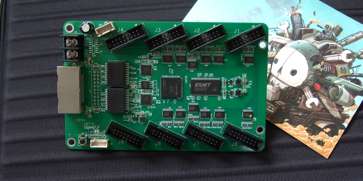
Our new part of the day is the ColorLight 5A-75B, a board that’s meant to drive eight of those ubiquitous high-density color LED panels over gigabit Ethernet. If you were building a commercia…
fluid cypress
stark storm
There's an article on Hackaday on the FPGA boards: https://hackaday.com/2020/01...
How much harder is programming this in C++ than a microcontroller
?
 high thorn
Hi, I really need help.
I got the Adafruit Hallowing M0 but for my design I can’t have the “Adafruit Industries Startup screen” I need the eye to start the eye directly. Can someone help me? I been trying to read on the website or find a how to youtube video with no luck. Can someone help me I can pay you for the help btw. Thank you
Info@dvjkingarthur.com

 terse moon
high thorn
Hi, I really need help.
I got the Adafruit Hallowing M0 but for my design I can...
terse moon
high thorn
Hi, I really need help.
I got the Adafruit Hallowing M0 but for my design I can...
Are you using the UF2 from the hallowing learn guide?
If so, my recommendation is to get TFT eSPI library on Arduino and load the example animated eyes example with the display driver for the hallowing
The Arduino programming language Reference, organized into Functions, Variable and Constant, and Structure keywords.
The display driver would be the ST7735
compact pebble
stark storm
That's what this was for: https://www.adafruit.com/product/1453 There are some...
Says product is discontinued
stark storm
fluid cypress
How much harder is programming this in C++ than a microcontroller
FPGAs aren't programmed in C++, they're programmed in Verilog or VHDL. However, it may be possible to have a fixed program on the FPGA that drives the LED panels, and just send it commands from a microcontroller.
stark storm
compact pebble
Says product is discontinued
Yes, that was an example, but alas that particular one is no longer available to buy. There should be similar products out there, however.
compact pebble
stark storm
Yes, that was an example, but alas that particular one is no longer available to...
So I should be searching for “LED Video Wall Controllers” then? How are they programmed? What kind of power do they take? Could I run it and the led matrix off a single portable battery pack?
stark storm
compact pebble
So I should be searching for “LED Video Wall Controllers” then? How are they pro...
There's this thing: https://hackaday.com/2020/01/24/new-part-day-led-driver-is-fpga-dev-board-in-disguise/
Our new part of the day is the ColorLight 5A-75B, a board that’s meant to drive eight of those ubiquitous high-density color LED panels over gigabit Ethernet. If you were building a commercia…
This prototype: http://cathodecorner.com/videocoat/index.html
And likely others. As for battery, luckily LED panels are multiplexed so they don't draw power for all their LEDs at once, so it's likely practical to run one and the controller from batteries somehow.
 modest skiff
Has anyone hacked a fitness tracker, and got its display to show something custom yet ?
 uncut nimbus
Hello! I am really new to adafruit and was wondering if anyone could tell me the difference between the adafruit pro trinket and an ardunio nano (I saw someone mention HID Mode online)? if I went with a nano could I still attach the ada powerboost 1000 for a lipo?
stark storm
The Pro Trinket is a pretty old product, it does without a USB-serial chip by emulating USB with software, which doesn't work terribly well with newer computers. There are several Arduino Nano variants available, each with different capabilities. For HID capabilities, you'll want a board with a chip that has built-in USB support (instead of software USB or a separate USB-serial chip).
From the AdaFruit end, you might want to look at the "ItsyBitsy" boards, which are compact but have more I/O than the really small plain Trinket boards, and at least some of them have nice HID support.
uncut nimbus
would the itsy bitsy work with the power booster 1000?
stark storm
I expect it would. I think the Nano would too.
uncut nimbus
brilliant thank you so much!
 autumn wren
What's the smallest push button with rotary encoder?
stark storm
autumn wren
What's the smallest push button with rotary encoder?
Alpha 318-ENC130175F-12PS?
It's about the same size horizontally as the PEC11 that AdaFruit sells, but it's shorter. Not sure which dimension(s) are most important to you.
The C&K RW series is pretty tiny, but doesn't include a push button
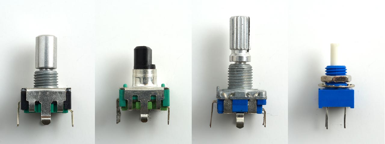

Left to right: AdaFruit, SparkFun, EC11 from AliExpress, Bournes 3315Y-001-016L (doesn't include push button)
autumn wren
stark storm
Alpha 318-ENC130175F-12PS?
thanks. darn they're all about the same size
autumn wren
stark storm
Alpha 318-ENC130175F-12PS?
what's the model name of the 2nd one?
stark storm
autumn wren
what's the model name of the 2nd one?
That's the Alpha one I mentioned
stark storm
autumn wren
What's the smallest push button with rotary encoder?
Apparently AdaFruit was listening, they just added this 11mm one: https://www.adafruit.com/product/5454

For projects that need a rotary encoder but need to keep it single-sided or need to avoid interrupting traces or devices on the other side, here's an all-SMT rotary encoder! It's a ...
 manic idol
modest skiff
Has anyone hacked a fitness tracker, and got its display to show something custo...
manic idol
modest skiff
Has anyone hacked a fitness tracker, and got its display to show something custo...
You might consider PineTime from Pine64
 drifting crystal
modest skiff
Has anyone hacked a fitness tracker, and got its display to show something custo...
drifting crystal
modest skiff
Has anyone hacked a fitness tracker, and got its display to show something custo...
Ooh! That would be nice!
I am actually looking for a hacker to hack an Oura ring! 😅💍💍
light wigeon
Well usually commercial devices disable their programming pins. And to open a fitness tracker since they are sealed/glued you basically have to destroy it
That is usually the issue with most commercial devices, the program it run is locked in and joined in a secure way to the display
and you can usually find something when you type some device +teardown ie: https://www.ifixit.com/Teardown/Oura+Ring+2+Teardown/135207
 light wigeon
ie: the MCU docs says this: "PSoC 6 MCU devices include extensive support for programming, testing, debugging, and tracing both hardware and firmware. All device interfaces can be permanently disabled for
applications concerned about a reprogrammed device or starting and interrupting flash programming sequences. All programming, debug, and test interfaces can be disabled."
And the MCU has a lcd driver on it
light wigeon
manic idol
You might consider PineTime from Pine64
And I mean, the oura ring patents have formulas/etc, for personal use you could technically implement their "stress" algorithm etc from the patents (if you do any commercial with it thought knowing their was a patent add x10 to the fine 😄 )
drifting crystal
Hello hackers and makers!
I'm working on building the best smart wearbles there will ever be -- a smart ring that does everything for you! e.g. Payment card, business cards, ID, COVID passport, keys for apartment/ office/gym, and more!
Since there is a chip shortage right now, is it possible to build, from scratch , NFC chips?
For context:


Anyone here wants to get in on this venture with me? Or is someone already working on something similar? 😁
💍💍
rapid radish
drifting crystal
Hello hackers and makers!
I'm working on building the best smart wearbles the...
The short answer is, no, it's not possible to build anything resembling a modern IC from scratch without significant resources.
stark storm
drifting crystal
Hello hackers and makers!
I'm working on building the best smart wearbles the...
It is probably possible to build a NFC transponder from scratch, but it would be a handful of chips, transistors, coils, capacitors, etc.
drifting crystal
Hmmmm... interesting.
One cannot make its own micro NFC chips without a lab...?
 rapid radish
Less of a "lab" and more of a "fab". The factories that make silicon wafers are... complex.
fluid cypress
Yeah it's a whole thing. Like if you have the cheapest process you're looking at likely 10s of millions
stark storm
A few people have made homemade transistors, and a few have made homemade simple integrated circuits. However, an NFC chip is a "mixed signal" chip, which is harder than pure digital or pure analog, and fairly complex. I wouldn't go so far as to say it's "impossible", but I also wouldn't recommend anything like that for someone's first effort.
drifting crystal
stark storm
A few people have made homemade transistors, and a few have made homemade simple...
Ahhhh. Got it!
"Not impossible".... noted! 😁💡💡
I am not much of a hacker, but eventually what I'd LOVE to create is a smart ring in which acts as an access card/keys of all sort, has one's ID/Driver's License, payment cards, and more.... everything from your wallet -> into one single ring 💍
Hefty goal, but 1,000% possible! 😁
rapid radish
drifting crystal
I am not much of a hacker, but eventually what I'd LOVE to create is a smart rin...
I'm not sure if you've seen it, but Adafruit does carry a product along these lines: https://www.adafruit.com/product/3041

What did Lord Sauron, when forging the One Ring in the fires of Mount Doom forget to include in his all powerful ring? What did he forget to leave out of the ring impervious even ...
stark storm
I was thinking RF430 chips would be a good choice for that, but of course they're out of stock lately.
drifting crystal
rapid radish
I'm not sure if you've seen it, but Adafruit does carry a product along these li...
Ah.. but only one functionally per ring...
rapid radish
drifting crystal
Ah.. but only **one** functionally per ring...
I know. Just a possible starting point for your project to test out the individual use cases in a realistic form factor while you figure out a chipset that can do everything you want.
manic idol
I would also recommend getting a Proxmark of some sort if you don't have one. Much easier in my opinion to get working software if you're building the hardware from scratch anyway.
Figure out all the functions you want at a basic level with the Proxmark. Then move to hardware design for the ring, including antennae and tuning circuitry, and then the software for the ring.
It might be easier to make the ring a to form of RF repeater or so Bluetooth-controlled gadget than telling to house all the brains and code and RF in something that small.
drifting crystal
manic idol
I would also recommend getting a Proxmark of some sort if you don't have one. Mu...
Hmmm ..makes sense...
Currently I'm inserting many chips (3, sometimes 4) chips into a ring. And user simply rotates the ring to the desired chip (output)
I'm not much of an engineer -- or hacker-- but I am learning little by little 😅😀
Would be awesome to hire someone too, on a startup-based compensation.
manic idol
drifting crystal
Hmmm ..makes sense...
Currently I'm inserting many chips (3, sometimes 4) chips...
Are you saying you have a functioning prototype that does this already?
rapid radish
drifting crystal
I'm not much of an engineer -- or hacker-- but I am learning little by little �...
Adafruit does have a jobs board if you want to pursue the hiring-someone option.
drifting crystal
manic idol
Are you saying you have a functioning prototype that does this already?
Yes.. 😀 💍💍
Our premature website: https://sites.google.com/view/brightsmartrings/home

1] No more carrying several payment cards!
drifting crystal
rapid radish
Adafruit does have a jobs board if you want to pursue the hiring-someone option.
That's awesome! I will definitely look into it!
I've seen Adafruit's Show&Tell YouTube videos, and there's definitely awesome (and extremely talented) people that I'd love to pick their brains..haa
manic idol
drifting crystal
Yes.. 😀 💍💍
Our premature website: https://sites.google.com/view/brightsmar...
Oh gotcha. If you have a prototype that works you're farther ahead than I gathered initially, might not be practical to do the Proxmark stuff, I thought you were still in the brainstorm/idea/draft design phase.
drifting crystal
manic idol
Oh gotcha. If you have a prototype that works you're farther ahead than I gather...
Ah. Yess.
I have pretty much tackled the "hardware" side of things, but not much on the software...
manic idol
What does your hardware run for software right now? And what's the underlying hardware controller/processor?
drifting crystal
manic idol
What does your hardware run for software right now? And what's the underlying ha...
I may have used the wrong terminology... haa. Hardware is a bit of an overstatement.
I simply figured out a primitive way to insert the NFC/RFID chips in a ring mold. 😝💍💍
 drifting crystal
I almost have all of my 4 primary cards from my wallet into one ring.
(Credit card, school acces card, business card, and ID).
The school acess card is surprisingly the hardest one.....😅🤔🤔
I bought this RFID copier to copy my school card into one of the RFID chips inside my ring, but no luck
....
 pure echo
Not all RFID tags are made equal. It might be worth investigating what kind of RFID tags your other cards are using?
 grand hinge
Yeah, proxmarks are very good for that sort of thing. I got one when I got my xSIID put in my hand and have found loads of uses for it doing other RFID stuff
drifting crystal
grand hinge
Yeah, proxmarks are very good for that sort of thing. I got one when I got my xS...
Whoa!! Eva! I never heard of xSIID, or Dangerous Things, until now! 🙌🤔🤔
💡💡
I'm following them now on Twitter! #BioHack + #TechForGood + #Productivity
drifting crystal
pure echo
Not all RFID tags are made equal. It might be worth investigating what kind of R...
Snap!... hmmmm that's tricky.
I guess it's best to use what @grand hinge said, a Proxmark?
manic idol
Depends how much you want to spend in terms of time and money. I own 2* Proxmark 3 Easy units, but gave up trying anything 13.35MHz because it's too hard. I can do 125kHz stuff all day.
grand hinge
Yeah, the xSIID is awesome. Still have an xEM that I've been meaning to put into my other hand, probably with my transit card on it
grand hinge
manic idol
Depends how much you want to spend in terms of time and money. I own 2* Proxmark...
Proxmarks are great but definitely on the pricey side. Also a decent bit of a learning curve involved to using it
manic idol
grand hinge
Proxmarks are great but definitely on the pricey side. Also a decent bit of a le...
That's why I like the "3 Easy" variant. Can do everything I need for like $60 instead of $300
manic idol
Yeah it's NOT compatible with the external antennas they recommend for implants though
grand hinge
Ya, having the larger antenna is definitely nicer for implants
Mine's between my thumb and forefinger so I can pretty easily move it around to the surface for scanning on smaller antennas
manic idol
Mine are also "generic" Amazon items, I compiled/flashed the semiofficial Iceman firmware myself
actually gave a talk at the local Linux User Group about it
grand hinge
Oh that's very cool
 south lark
It starts out cool. Then 300 years later an entire new high tech society is born that starts forcing assimilation on people to add their distinctivenesses to the collective.
drifting crystal
Anyone here interested in startups/entrepreneurship? 🤔😀
a.k.a: Building something that the entire world can benefit from? *not just some people... but the entire world! 🌏
If so, let's work together! 🤝
pure echo
drifting crystal
Anyone here interested in startups/entrepreneurship? 🤔😀
a.k.a: Building somet...
If you're looking to hire someone to fill a paid position, please post your job listing through https://jobs.adafruit.com/.
Find maker jobs in 3D and CAD, Art, Design, Education, Embedded Development, Engineering, Fabrication, Marketing and Communications, and Web Development
drifting crystal
pure echo
If you're looking to hire someone to fill a paid position, please post your job ...
Perfect! Will do!
One inquiry: I can post the job/opportunity as a combination of an early company salary and equity compensation (% ownership of the company? Or must it be only salary?
Thank you!
pure echo
drifting crystal
Perfect! Will do!
One inquiry: I can post the job/opportunity as a combination...
To my understanding, there aren't really any rules against it. If the compensation field doesn't physically accept it, you could leave it blank and share that information in the description instead?
main lion
I'm wanting to make some neopixel based earings. I'm using the plastic milk bottle lids the 12 NeoPixel ring sits just inside perfectly the earring will be 2 or three of these bottlelids thick the back will have a qt py (will test with a few boards to see what will work best bang for $$$) inside the back lid will be the lipo BFF and a 100 mah battery larger batries wont fit the space. I'm concerned that the BFF charger is set to work for a larger battery and might cause problems (over heating or exploding might be dangerous especially if I'm on a crowded dance floor when it goes boom is this a rean concern or is there a way to limit the charge current via code or some other treak of the hardware
long mango
main lion
I'm wanting to make some neopixel based earings. I'm using the plastic milk bot...
The first three chargers here have an out-of-the-box 100mA charge current, which is fine for the tiny 100maH battery: https://www.adafruit.com/?q=micro+lipo&sort=BestMatch
main lion
using a lipo charger that is intergrated into my project is kind of necessary don't want to have to pull it all apart to charge it back up or is that not possible with the bff and the 100mah battery.
stark storm
main lion
I'm wanting to make some neopixel based earings. I'm using the plastic milk bot...
The BFF supports a 200mA charge rate, which is a little much for a 100mAh cell. However, if you're capable of it, changing the charge programming resistor on it to 10kΩ would make it act as a 100mA charger, which would be fine. The chargers danh mentions are also 100mA chargers.
main lion
stark storm
The BFF supports a 200mA charge rate, which is a little much for a 100mAh cell. ...
However, if you're capable of it, changing the charge programming resistor on it to 10kΩ would make it act as a 100mA charger, which would be fine. I think I'm able but a Picture would help I'm not super confidant in what needs to be done.
rapid radish
main lion
However, if you're capable of it, changing the charge programming resistor on it...
It'd be the "512" resistor next to the main charger chip in the middle of the board, right above the "LiPo" silkscreen label.
main lion
to me that resister seems to be 1/2 under the switch am I needing to remove the switch to remove the resister and then place the 10KΩ resister in its place or do I have the wrong resister
rapid radish
I don't have a board myself, so I'm just going by the photos on the site. This is the resistor I mean.
 main lion
rapid radish
It'd be the "512" resistor next to the main charger chip in the middle of the bo...
main lion
rapid radish
It'd be the "512" resistor next to the main charger chip in the middle of the bo...
Thanks @rapid radish the word lipo seems to have tiny resistors above and below the leter o (of lipo) with the switch covering the right end of the resistors then there is a tiny IC chip then....... thanks so much for the photo that I think is do able thank you so much
rapid radish
Gotcha. Those aren't resistors, just the feet of the switch itself.
drifting crystal
This is a general question.... but these NFC tags/stickers act different with iPhone.
The big NFC sticker works on every tap with iPhone, but the micro NFC does not. I have to keep on tapping and playing around with it.
Size matters with respect to latency? Hmmmm🤔🤔

 stark storm
I wonder if one is a low frequency tag and one is high frequency
drifting crystal
I looked at both specifications and both seems to have the same specs. (NFC tag 215)
.
 night bolt
Question: I bought the adafruit ultra skinny led strip https://www.adafruit.com/product/4368, and am wondering what's the smallest micro controller that I can use to drive it? (I want to attach to big safety glasses) I thought about the trinket m0, but that uses 3V logic, so I'm not sure if that would drive 5V LED strips
Bonus points if the board uses circuit python and/or has integrated charging/usb power
Please ping me if you have an answer, or a suggestion of a better channel to post this in.
stark storm
night bolt
Question: I bought the adafruit ultra skinny led strip https://www.adafruit.com/...
You can use any controller plus a level shifter. The ItsyBitsy boards are pretty small, and include a built-in level shifter. The third possibility is to reduce the power supply voltage to the strip, so that the 3.3V logic is closer to the supply voltage. Many designs do this by powering the strip from the same LiPo cell powering the controller, thereby powering the strip from 3.7V. While this is technically below the specified voltage, it works pretty well. Others with a 5V supply add an ordinary silicon diode between the supply rail to subtract the 0.6V drop of the diode, yielding a 4.4V supply to the strip, which also gets the 3.3V signal in range.
 rancid plank
stark storm
You can use any controller plus a level shifter. The ItsyBitsy boards are prett...
rancid plank
stark storm
You can use any controller plus a level shifter. The ItsyBitsy boards are prett...
i feel like the diode hack needs to be documented in more places, given how common 3.3V MCU boards are these days. also maybe document better that 3.3V can be a usable supply voltage for NeoPixels
 knotty hollow
the diode hack is probably not the most energy efficient, ?dumping 13% of the energy used as heat through the diode?
though the next best option is probably vastly more expensive/bulky
rancid plank
energy efficiency optimization is a whole topic of its own, i think. running off the 3.3V regulator on a dev board is also going to waste a decent amount of energy. high-current LDOs aren't cheap, switching regulators can be finicky, etc.
knotty hollow
basic regulators also dump the voltage difference as heat IIRC
stark storm
The LEDs are current regulated, so when running them from 5V they just dissipate the energy (and heat) in the control chips instead of in the diode. The only way around it is switching current regulators, and I don't know of any addressable LEDs that use that approach (it would be complicated, expensive, and bulky)
knotty hollow
I think the pico has some sort of awesome thing for its regulator? but it probably isn't ampy enough for many lights.
stark storm
Yeah, it uses a nice buck-boost chip capable of 800mA
rancid plank
800mA? wow. the usual Feather LDO is only 500mA, i think
stark storm
But you're right, a switching regulator instead of a diode could be more efficient.
Yeah, LDOs are linear, switchers are more efficient and in this case, also capable of delivering more current
rancid plank
i've read some stuff about low-power design, and a lot of it apparently involves eliminating regulators to the extent that the parts will tolerate it (harder to do with off-the-shelf Adafruit boards, maybe)
knotty hollow
I suppose at 800mA you could support 10 neopixels, I may try this....
rancid plank
you can support way more than that as long as you don't run them at full brightness white
stark storm
My usual thinking about low-power design is to use efficient (switching) regulators, and sometimes I'll have multiple regulators, one for each subsystem, and shut down the ones I'm not currently* using. * pun intended
 silver token
smarter sybsystem
knotty hollow
yeah, I figured I'd frontload the foolproof number, theoretically you could have 500 generally off neopixels on that supply
rancid plank
with that many, the idle current of the driver chips might not be negligible
knotty hollow
I assume its little more than 1mA per
but again, I now have more ideations, I could probably run a 64 pixel board with 8 lights at full
or use a current limit preprocessor on my output so I can turn more of my brain off while doing the pixelarts
rancid plank
if you're using CircuitPython, it has a global brightness setting. it will cut into your color depth, but sometimes that's OK
knotty hollow
I like the idea of getting full range until I go off the rails with a parachute
though uses more CPU my way (and doesn't fix any color depth concerns either)
rancid plank
i guess if you're writing a library to deal with it, you could have a "debug" mode for blackout on exceeding calculated current limit, and a mode for scaling back brightness instead for "production"
knotty hollow
and I guess that could run for a couple hours on a 18650 cell
rancid plank
also, i find that NeoPixels are painfully bright even at half-on. probably especially so for something you're wearing next to your eyes
knotty hollow
yeah, I was just gabbing here, but smells like viable project now...
rancid plank
have you lit them up yet?
knotty hollow
I have rings and grids, etc, haven't lit a one with years of time to do so (ignoring my CPX/MacroPad)
night bolt
stark storm
You can use any controller plus a level shifter. The ItsyBitsy boards are prett...
Thank you so much for the succinct reply. I'll look into this further
 prisma anchor
very basic question. If I want my garment to show a light-up pattern, kind of like a neon sign, is it reasonable / common to just attach a flexible LED strip to the garment? Like https://www.adafruit.com/product/4848
Here at Adafruit we love discovering new and exotic glowing things. Like moths to the flame, we were intrigued by these 'chip on board' ultra-flexible LED Strips with 352 SMT LEDs ...
amber widget
@prisma anchor Sure! Be aware that those neon-like strips are pretty chonky though. But you have the right idea!
prisma anchor
Awesome, thanks Kattni! Lookin' into it now
does one typically glue fabric feet to the ends of the strip and then sew the feet into the garment, or what?
amber widget
You can do that, you can sew a channel into the garment and slide the LEDs into the channel, you can also straight up sew around the strip, but that's a lot of thread that would kind of show through to the outside of the garment.
Sewing a channel is pretty common though. So take a strip of fabric, and sew up each side of it to create a channel down the center of it.
prisma anchor
oh wow, good idea
amber widget
If you cut the strip properly, you can make it into a shape and the strip could follow the shape.
prisma anchor
apparently the thing I linked can be cut down to size. does that expose some wires that you then attach a new terminal to and heat shrink, or what?
amber widget
Exposes the strip. Thing is, you'd have to remove the strip from the garment to wash it anyway, so it's of less concern in that case. However, to protect from say, sweat and rain, you could seal off the cut end with something like hot glue or some other silicone sealant. Something non-conductive obviously.
If you want to use the cut piece you'll have to solder wires to the new chunk of strip. Which you can also seal.
prisma anchor
what is "the strip" that's exposed? I can't really tell from the product photos
amber widget
So, if it can be cut to size, you're cutting the silicone sheath and the LED strip both.
That means the sheath is no longer one piece, and therefore no longer sealed.
prisma anchor
yeah. is the inside the same kind of thing as those thin strips dotted with LEDs that you see in restaurant windows?
yep
amber widget
The inside is a strip of super-high-density LEDs.
prisma anchor
oh so they're still discrete units, there's just a ton of them?
amber widget
So, probably too high density to even differentiate unless you're were looking really closely with them off.
Yeah.
prisma anchor
wow I did not know that
amber widget
Said 480/m didn't it?
prisma anchor
352 yeah
amber widget
(There's a couple of options for these in the store, I might be conflating two.)
OK yeah
prisma anchor
that's a lot of freakin LEDs. Sounds fun.
what I'm trying to discern is, when I cut the strip, what connections will I expose (power and some kind of control signal?), and how will I attach to them (solderable?)
amber widget
In theory, if you cut it in two pieces, you should be able to add wires to the second piece to use it. But be aware that working with that level of high-density can be frustrating at the very least. Tiny tiny tiny places to solder to. Always plan to sacrifice a few individual LEDs to do so.
That I'm not sure about, and that's exactly what I'm talking about above. 😄
I've never cut one apart
prisma anchor
what do I get if I sacrifice a bunch of LEDs? The ability to solder to where they were?
amber widget
Yeah exactly.
prisma anchor
and I get them off by desoldering?
amber widget
Like, you'll lose one or two when you cut it.
amber widget
prisma anchor
and I get them off by desoldering?
Only if necessary.
There might be tiny pads somewhere on the strip.
Or solder points
Etc.
Low density strips almost always have those, and they're easy to get to and find, because there's so much space between. the LEDs.
High density, less space, less options.
prisma anchor
is a lower-density strip like this essentially the same thing just with more room for error? https://www.adafruit.com/product/3811
Adding glowy color to your projects has never been easier: no more soldering or stripping wires, clip 'em on and glow! This Adafruit NeoPixel LED Strip with Alligator Clips has 30 total ...
amber widget
You won't need to remove more than 2 I'd say to get what you need, if that is necessary.
amber widget
prisma anchor
is a lower-density strip like this essentially the same thing just with more roo...
So, kind of. That requires a microcontroller, not only power.
And also doesn't have the same neon diffusion.
prisma anchor
right - I think I want to steer clear of NeoPixels because I don't want to be locked into Adafruit's control rig. I'd rather use what the rest of the world uses.
amber widget
That's entirely fair.
It's the neon diffusive sheath that makes it look like neon. The strip itself probably wouldn't.
pure echo

Here at Adafruit we love discovering new and exotic glowing things. Like moths to the flame, we were intrigued by these fresh Flexible Silicone Neon-Like LED Strips! They look a lot ...
amber widget
Yeah we were talking about another version in the shop, but that's the other option.
pure echo
Yeah, was suggesting it as a NeoPixel alternative if you want to go controller-less
prisma anchor
pure echo
https://www.adafruit.com/product/3867 exists?
nice - no control signals at all it seems?
amber widget
@prisma anchor It occurs to me that Noe and Pedro made signs with these that involved cutting the strips, if I remember correctly.
pure echo
Nope, just voltage and it lights up.
amber widget
Check Adafruit Learning System for a guide. That might answer your questions about wiring them together.
Once cut.
I'm uncertain of that, but it might.
prisma anchor
nice. I'll have a microcontroller anyway, but switching a control-less LED strip with a relay attached to the mcu is nice and simple.
amber widget
Ah fair enough.
Hm looks like they used the NeoPixel ones.
I swear we have a guide on using the "dumb" ones.
prisma anchor
am I remembering correctly that it's hard to make big strips of individually addressable LEDs and that's why neopixels exist and why they have complicated control logic?
amber widget
Found it! https://learn.adafruit.com/led-neon-signs/build-the-neon-sign#splicing-neon-led-strips-2997760

Adafruit Learning System
Make your own neon-style signs with LED "neon" strips. Animate the sign with a Metro M0
prisma anchor
amber widget
Found it! https://learn.adafruit.com/led-neon-signs/build-the-neon-sign#splicing...
aw yeah 👍
amber widget
prisma anchor
aw yeah 👍
Not sure which version those are, but that's what you might find in either.
rancid plank
prisma anchor
am I remembering correctly that it's hard to make big strips of individually add...
DotStar (APA102) LEDs are less complicated because they basically talk SPI (at the cost of an additional wire in the chain)
prisma anchor
rancid plank
DotStar (APA102) LEDs are less complicated because they basically talk SPI (at t...
right ok, so it's a cost of 1 additional wire, not something that scales linearly with the number of LEDs in the strip
or do both kinds of strips have a control chip per each handful of LEDs or something
rancid plank
they both have control chip per LED; otherwise you need to hook them up with some sort of multiplexing that ends up with order of sqrt(N) controllable wires total (where N is the number of subpixels)
prisma anchor
yeah, makes sense. A priori there is clearly a theoretical scaling limit, I just wasn't sure if chips these days are so good that no hobbyist LED strip would in practice exceed their limits
though also if you don't have a chip per handful of LEDs then the strip isn't cuttable
amber widget
You'll need to inject power in multiple places long before you'll reach a length that reaches a control limit.
prisma anchor
ah nice
rancid plank
each internal control chip can act like a repeater, so the practical limits are mostly voltage drop (like kattni said, injecting power at multiple points helps) and how long you're willing to wait for the whole string to update
(on an 8-bit MCU, you're likely to run out of RAM, but that's less of a problem with modern 32-bit MCUs)
prisma anchor
thanks so much for the help @amber widget @rancid plank @pure echo!
amber widget
You're entirely welcome!
 high wolf
hi all. i want to do a wearables project that changes the color of sewable neopixels with different GPS coordinates. I've got a stemma QT GPS I've used with a RP2040 (circuitpython), but i'm wondering if i should go back to the flora (arduino) to provide for more mobility, etc. with conducive thread and all. any suggestions?
(Was thinking perhaps a shirt or scarf version of the GPS jacket, if that rings a bell)
rancid plank
high wolf
hi all. i want to do a wearables project that changes the color of sewable neopi...
looks like Gemma M0 supports CircuitPython, and you might have enough pins for a NeoPixel string plus I2C (though the flash and RAM might be a bit on the small side for that?)
high wolf
rancid plank
looks like Gemma M0 supports CircuitPython, and you might have enough pins for a...
Oh cool; I do own a Gemma M0 and i just found doc of it working with the GPS - https://www.mouser.com/pdfdocs/adafruit-gemma-m0.pdf