#general-chat
1 messages · Page 90 of 1
 quartz marsh
You mean, coolest-looking 🤣 There is two linear regulators there that have about 40% efficiency, and I didn't realise why this would be an issue until I noticed the bottom of my robot acting as a free hand-warmer
 jagged citrus
quartz marsh
You mean, coolest-looking 🤣 There is two linear regulators there that have abou...
jagged citrus
quartz marsh
You mean, coolest-looking 🤣 There is two linear regulators there that have abou...
Yes
Genuinely great design
quartz marsh
Thanks so much 🙂 can't go wrong with purple soldermask and HASL (lead-free, of course) finish
I will admit though, the layout on that one was pretty awesome
jagged citrus
True, purple boards are always the coolest ones
quartz marsh
Either that, or black and ENIG
 stoic mesa
nice.
haven't used this one yet.
do you program the whole thing in Python or Arduino IDE?
jagged citrus
quartz marsh
Either that, or black and ENIG
Matte black premium finish
quartz marsh
jagged citrus
Matte black premium finish
Ooh yeah that would be cool, haven't tried it out yet though
quartz marsh
stoic mesa
nice.
haven't used this one yet.
do you program the whole thing in Python or A...
Arduino IDE. I've heard that Python limits something like an ESP32-S3 down to laughable speeds, but I'm not exactly sure. I kind of 'grew up' with Arduino though, so it made sense for me to either use that, or go straight to ESP-IDF (something I also haven't tried out yet)
stoic mesa
my robot has a master MCU that is programmed in Python and a secondary MCU that takes care of low-level operations such as PID control of motors and is programmed in Arduino.
this way, I have best of both worlds
jagged citrus
Circuitpython seems a bit iffy on the S3, i had many issues with wifi
quartz marsh
stoic mesa
my robot has a master MCU that is programmed in Python and a secondary MCU that ...
Which MCUs?
stoic mesa
master is esp32-s3 (I use Adafruit feather), slave is samd21
quartz marsh
jagged citrus
Circuitpython seems a bit iffy on the S3, i had many issues with wifi
Interesting...
quartz marsh
stoic mesa
master is esp32-s3 (I use Adafruit feather), slave is samd21
Oh, that's cool
Have you noticed any benefits of circuitpython vs Arduino?
Is uploading quicker or anything like that?
stoic mesa
if you are interested, here is my bot:
https://yozh.readthedocs.io
main reason I chose python (micropython , not circuit python) is educational: my bot is to be used for teaching kids
quartz marsh
Wow, very nice!
jagged citrus
quartz marsh
Have you noticed any benefits of circuitpython vs Arduino?
I prefer circuitpython for simpler things or projects that use SD card storage since i like how circuitpython handles it, for projects with displays or wifi i use arduino and PlattformIO
quartz marsh
jagged citrus
I prefer circuitpython for simpler things or projects that use SD card storage s...
Cool
You know, I've been kind of drifting away from ESP32 recently, and more inclined to start messing around with Linux SBCs...
jagged citrus
quartz marsh
You know, I've been kind of drifting away from ESP32 recently, and more inclined...
Have you looked into new boards like the Milk-v and luckfox pico?
quartz marsh
Or STM32, but the performance benefits on STM32 are not incredibly much
quartz marsh
jagged citrus
Have you looked into new boards like the Milk-v and luckfox pico?
Yes, I've bought the luckfox pico and did some minor testing on it
The main thing is, I want to start using BGAs in my designs
Just to see, since that's the next step
stoic mesa
quartz marsh
You know, I've been kind of drifting away from ESP32 recently, and more inclined...
but then you certainly need a secondary MCU. You can't do anything that requires tight timing, like reading motor encoders, on a SBC
quartz marsh
stoic mesa
but then you certainly need a secondary MCU. You can't do anything that requires...
Thanks for letting me know, I wasn't aware of these sorts of things
I thought since the processor would be much faster, it would be able to handle such things
But, I guess it makes sense
Speaking of which, @stoic mesa , have you ever made a balanced multi-cell LiPo charger, as in, for things like in your robot?
Or, is it like if you put 2 cells in the Yozh they just get paralleled?
stoic mesa
I use parallel.
quartz marsh
Fair enough

Just finished making a footprint for a half-bridge motor driver because it's so new the KiCad footprint isn't even there
stoic mesa
which one?
quartz marsh
DRV8145-Q1
stoic mesa
do you really need currents over 10A? what motors do you use?
quartz marsh
stoic mesa
do you really need currents over 10A? what motors do you use?
Lol I'm going to make a BLDC ESC from scratch
(Try to)
With FOC
(Maybe)
(If it works)
stoic mesa
🙂
quartz marsh
I have no idea though honestly
Seems like I can just throw 3 of those together and some sort of back EMF system
Anyways
Been nice chatting with you guys
Goodnight (I'm in Australia lol)
jagged citrus
quartz marsh
Goodnight (I'm in Australia lol)
See ya
 patent hemlock
wow
 round minnow
stoic mesa
if you are interested, here is my bot:
https://yozh.readthedocs.io
round minnow
stoic mesa
if you are interested, here is my bot:
https://yozh.readthedocs.io
Is the source for the firmware available? I'm interested in options like that for a robot I am tinkering with. Protocols and implementation to use for the lower level 'nervous system'.
stoic mesa
round minnow
Is the source for the firmware available? I'm interested in options like that fo...
yes, see https://github.com/shurik179/yozh
It can use soem work, obviously, but it works.

GitHub
Small robot based on Pololu's Zumo chassis but programmable in CircuitPython - shurik179/yozh
 hard halo
dude, dictator Maduro invited Elon Musk to a personal fight and he accepted 😂
I am laughing since yesterday
According to Maduro, Elon ( with Bolsonaro and Milei ) will send missiles to Venezuela
https://x.com/elonmusk/status/1818845968890019936 (see the memes!!!)
I’m coming for you Maduro! 🚀💣
I will carry you to Gitmo on a donkey 🫏
 Twitter
·
round minnow
stoic mesa
yes, see https://github.com/shurik179/yozh
It can use soem work, obviously, but ...
Twitter
·
round minnow
stoic mesa
yes, see https://github.com/shurik179/yozh
It can use soem work, obviously, but ...
If my browsing of the code is accurate, firmware controls servo postion, motor speed and acceleration based on settings from the brain via I2C. Firmware reads (enabled) sensors and populates a buffer (registers) that the brain can read via I2C.
In the described scenario, the firmware is not being touched. Only accessed from the brain using I2C in circuitpython or micropython. That firmware could benefit with some refactoring, to move blocks of code into functions. That would simplify the setup and loop logic. It does not look like that firmware is very large. It should not be pushing the limits of the target device. More advanced students could add additional logic to the firmware.
stoic mesa
round minnow
If my browsing of the code is accurate, firmware controls servo postion, motor s...
yes, that is correct. I'd also add that the firmware also reads IMU and does data fusion, providing easy to use roll/pitch/yaw angles to master MCU.
And certainly, some refactoring coudl be useful.
If you are willing to help, let's talk!
round minnow
(initial) refactoring of the code would be easy, but I do not have the hardware needed to test it.
I grouped the IMU with sensor reading. I had not noticed the sensor fusion logic. Did not look at the imu.cpp code.
 rancid bloom
just noticed the captcha at the bottom Adafruit blog pages... clever and educational! Love it.

 glad ruin
hard halo
https://x.com/elonmusk/status/1818845968890019936 (see the memes!!!)
glad ruin
hard halo
https://x.com/elonmusk/status/1818845968890019936 (see the memes!!!)
Oh Maduro is insane. I can't find it because youtube search only gives me stuff from the last two days, but there are some hilarious clips of him trying to english.
hard halo
glad ruin
Oh Maduro is insane. I can't find it because youtube search only gives me stuff ...
I miss Harry Truman, Dwight Eisenhower, Lyndon Johnson, Richard Nixon, J. F. Kennedy, Ronald Reagan, Gerald Ford they would not allow communism ditactors like him in all America south to north.
glad ruin
They all had their fair share of issues, but let's not get into that.
I think it is fair to say that there is no such thing as a "friendly" dictator, communist or otherwise.
 solar kindle
All the STL models and instructions in case anyone wants to try it out. And, y'know, do any coding improvements.
https://www.printables.com/model/960905-bluetooth-membrane-keyboard-65-style

Printables.com
A membrane keyboard in the style of a "65% keyboard", with Bluetooth capability | Download free 3D printable STL models
 fleet rampart
just made and ordered this tonight 
 jagged citrus
glad ruin
I think it is fair to say that there is no such thing as a "friendly" dictator, ...
jagged citrus
glad ruin
I think it is fair to say that there is no such thing as a "friendly" dictator, ...
There is no such thing as a good dictator, all of them are terrible, maduro is just like how pinochet was during the 1973 dictatorship here in chile.
Same thing, different coat of paint
Thats probably the most political thing ill say in this server, aside from me thinking that burger king is better than mcdonalds but that would get way too heated very quickly
patent hemlock
yeah, you'd definitely be in for a grilling
 twilit pawn
Hey all!
I've been referred here since I asked a similar question in a different tech-related discord.
I kind of want to start out on breadboards and prototyping, but I can't really find a decent store to get supplies. I live in the Netherlands, and might be quite limited in which shops are available.
I did find mouser, but it seems like it's way over the top for what I need and want.
I kind of want to start out with a few things Ben Eater on youtube was showing, and even though I do want to support the guy, it's just not feasable to do that through his webshop given it'll take additional transport costs, and import costs and such.
So my question here is for advice for EU-based (preferably even NL based) shops I can visit (web or physical) to start looking around for materials, tools, and other supplies to start out.
If I need to move this question to one of the #help channels, I'd be happy to 😁
Thanks in advance
jagged citrus
patent hemlock
yeah, you'd definitely be in for a grilling
Good one
solar kindle
jagged citrus
Thats probably the most political thing ill say in this server, aside from me th...
So, you ally yourself with the royal elite rather than good, hard-working farmers? 😜
jagged citrus
solar kindle
So, you ally yourself with the royal elite rather than good, hard-working farmer...
BK tastes better
Big mac more like mid mac
stoic mesa
twilit pawn
Hey all!
I've been referred here since I asked a similar question in a differen...
Mouser has European division: https://eu.mouser.com/
But mouser is huge - tens of millions of components - so you need to know what you are looking for.
For parts for hobby makers, check Pimoroni (UK)
and for cheap generic things, Amazon and AliExpress are also an option (when used carefully)
twilit pawn
Thanks! That helps!
it seems like a decent retailer for a lot of supplies, though not all. But that's fine, it's a decent start!
stoic mesa
there is also https://lectronz.com/
where small independent makers sell their own creations (like Tindie in the US).
That's more of a niche thing, but occasionally you find something cool there.

Lectronz.com is a marketplace for electronic enthusiasts with a focus on the open-hardware and DIY electronics community.
twilit pawn
Yea I saw a retailer in the US that sold a kit I wanted, but since buying from there was an incredibly high shipping cost, and import costs, it would be cheaper and faster to get it locally(ish)
patent hemlock
if you're just starting, i would highly recommend looking at those "getting started in electronics" kits as they supply all the also the parts and instructions for what i would consider a mostly reasonable introduction to general electronics usage
 dusty citrus
twilit pawn
Hey all!
I've been referred here since I asked a similar question in a differen...
dusty citrus
twilit pawn
Hey all!
I've been referred here since I asked a similar question in a differen...
Don't go through distributors they're expensive af for hobbists. In the eu the cheaper option is AliExpress, you get whole boards cheaper than the main ic from distributors
twilit pawn
dusty citrus
Don't go through distributors they're expensive af for hobbists. In the eu the ...
Sadly the Ali Express things are bad quality in a lot of ways 😅 especially the breadboards.
Plus I never use ali express for the very simple reason that it is not a safe website to leave any personal information on. Same as wish and temu.
rancid bloom
solar kindle
All the STL models and instructions in case anyone wants to try it out. And, y'k...
I didnt know why I purchased a roll of conductive tape years ago. Thank you for showing me the light. :awesome:
dusty citrus
twilit pawn
Sadly the Ali Express things are bad quality in a lot of ways 😅 especially the...
I'm not going to convince you, but well you're wrong, I never had any problem with it, it's just like the Chinese ebay that ships outsea.
If you really want to go through distributors, lcsc is cheaper
Wish and temu are more recent, mostly overexpensive dropshipped garbage sold through heavy marketing
You just need to be carefull with active components like stm, there are lots of clones, which not all of them are bad either.
AliExpress is mostly gray market, but there's paypal, and alipay
twilit pawn
I mean you might be right, but the times I had to fix data leaks that happened through Ali Express, as well as the dropshipped garbage just made me never share any information there.
Granted I might be a bit overparanoid for Ali Express, Ebay, Wish, Temu, and all those other "We sell everything dropshipped"
There might be 1 or 2 I sort of trust, but only for things that don't really matter 😅
Regardless, I did check out the breadboards on ali express, and they are all garbage quality, so I'm not even going to check for a 65C02, or a 555-timer on there 😅
stoic mesa
for components, LCSC is somehwat cheaper than Mouser, and it is mostly reliable (certainly more so than AliExpress). Their parametric search sucks, though, and shipping takes some time unless you are willing to pay extra for fast shipping.
twilit pawn
is it EU-based tho?
dusty citrus
twilit pawn
is it EU-based tho?
CN
There's no point to buy locally unless you have like a gold mine or have a business
Otherwise there's stuff like octoparts for distributors pricing
Digikey ships for free for orders over 50€, at least in italy, nl idk
twilit pawn
thanks! I'll have a look into DigiKey I guess 😅
I bet sourcing locally is going to be a huge pain. Thanks for the advices allround tho
 somber spindle
twilit pawn
thanks! I'll have a look into DigiKey I guess 😅
I bet sourcing locally is goin...
somber spindle
twilit pawn
thanks! I'll have a look into DigiKey I guess 😅
I bet sourcing locally is goin...
Check out TME or Farnell (UK)
 cloud pilot
Why does my DPDT switch not turn on the board unless I switch it on, then off, then on again???

 late fulcrum
Looks like you're trying to switch both power and enable?
 trail bridge
anyone know what specific port of gnu boy and nofrendo were used in the QT Py emulation yt vids (https://www.youtube.com/watch?v=uo2TKCRYRoo, https://www.youtube.com/watch?v=uF6tlsejnhw)
For the nofrendo one, I found https://github.com/adafruit/nofrendo_arcada, but that is specific for the arcada hardware. I wanted to be able to customize it for custom hardware (I can provide my own tft support (ideally with an adafruit gfx object) and my own input logic etc)
cloud pilot
late fulcrum
Looks like you're trying to switch both power and enable?
I thought enable was to turn off the feather? I could be wrong though
solar kindle
rancid bloom
I didnt know why I purchased a roll of conductive tape years ago. Thank you for ...
I first tried conductive ink but the foil tape turned out to be much more reliable. I even used it to re-do a little 3×2 keypad I have attached to my laptop for special characters that I use a lot.
 rancid bloom
solar kindle
I first tried conductive ink but the foil tape turned out to be much more reliab...
rancid bloom
solar kindle
I first tried conductive ink but the foil tape turned out to be much more reliab...
Thats amazing! I gotta figure out where I stored that roll… 😏
 thick wind
cloud pilot
I thought enable was to turn off the feather? I could be wrong though
thick wind
cloud pilot
I thought enable was to turn off the feather? I could be wrong though
Connecting enable to ground disables the 3.3v regulator.
 rancid bloom
solar kindle
I first tried conductive ink but the foil tape turned out to be much more reliab...
rancid bloom
solar kindle
I first tried conductive ink but the foil tape turned out to be much more reliab...
How much pressure does it take? And how much math do you do that you need a pi key. 😅
solar kindle
rancid bloom
How much pressure does it take? And how much math do you do that you need a pi k...
It's a pretty light touch. Depends a lot on the type of filament you use and on the type of sticker paper.
 weary fiber
solar kindle
I first tried conductive ink but the foil tape turned out to be much more reliab...
weary fiber
solar kindle
I first tried conductive ink but the foil tape turned out to be much more reliab...
having distinct buttons for em/en dashes is so cool
late fulcrum
cloud pilot
I thought enable was to turn off the feather? I could be wrong though
My thinking is that you need either)or but not both but I could be missing something
cloud pilot
whys my feather m0 express saying i have 0 bytes free?

its fresh outta the box. wheneever i drop a uf2 into it, the feather does not change to circuitpy
 ebon dew
cloud pilot
whys my feather m0 express saying i have 0 bytes free?
ebon dew
cloud pilot
whys my feather m0 express saying i have 0 bytes free?
To load circuit python the drive has to be in bootloader mode. The drive should show up as BOOTPY. You cannot drag a UF2 to the drive while in normal mode.
well you can but then the UF2 will just sit there doing nothing and will take up all the space as you're seeing.
cloud pilot
i did do that it still is acting up:(
ebon dew
while in bootloader mode when you drag the UF2 to it, it will load and the UF2 file will disappear. then you reset your device and the USB drive should show up as CIRCUITPY.
cloud pilot
i drag the UF2 when its in this mode, correct?
 ebon dew
yes
cloud pilot
i did that but its not popping up as circuit py
ebon dew
after a hard reset?
cloud pilot
its really weird cause ive done this over 10 times and use the exact same files every time
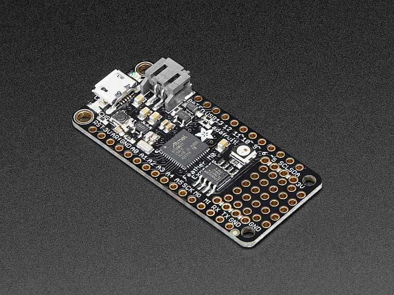
The Adafruit Feather M0 Express was one of the first development boards designed for CircuitPython by Adafruit. Unlike the original Feather M0 Basic, it added a NeoPixel status LED and external 2 MB SPI Flash for storing CircuitPython code.It is a great entry into the Feather ecosystem with Circu...
i tried using this uf2 as well but still doesnt work
how do i do a hard reset?
ebon dew
just hit the reset button once
that's a hard reset
a hard reset is always required after a UF2 update
i might have an m0 express i can test it on if you can't get it to work.
cloud pilot
gotcha, yea i tried that too :/ i did a hard reset, dragged my uf2 thats alwyas worked, dragged in the latest uf2, and it still doesnt bring up circuitpy
ebon dew
hmm i only have an m0 wifi not express
and the m0 wifi can't run circuit python anyway. :/
 ebon dew
apparently i don't own an m0 express feather. :/
cloud pilot
this is what it looks like when i hit reset twice
 ebon dew
ok what is the contents of info_uf2.txt while in featherboot?
cloud pilot
UF2 Bootloader v3.16.0 SFHWRO
Model: Feather M0 Express
Board-ID: SAMD21G18A-Feather-M0-Express-v0
ebon dew
ok the latest bootloader version is 3.7, can try updating the bootloader
at the bottom of this page you should see a link to download the bootloader https://learn.adafruit.com/adafruit-feather-m0-express-designed-for-circuit-python-circuitpython/uf2-bootloader-details

bootloader UF2 is different than a circuit python UF2
after you update the bootloader then try to update the circuit python uf2
cloud pilot
so ill drag update-bootloader-feather_m0_express-v3.7.0 into FEATHERBOOT and then this one?:
 ebon dew
correct
ensure it updates by allowing windows to redetect the drive, it might take a few minutes.
you'll see some windows notifications about the drive being detected, usb, etc...
cloud pilot
okay so i did that, got the notification and now the drive disapeared, the neo pixel is blinking green every 5 seconds or so, should i just wait for it to pop up or hit reset ?
ebon dew
your info_uf2.txt should update to show it's on bootloader 3.7
hit reset once
it should then bring up the usb drive again. then go back into bootloader mode. confirm info_uf2.txt says bootloader 3.7. then drag over the circuit python uf2.
cloud pilot
T^T

the FEATHERBOOT now reads:
UF2 Bootloader v3.7.0 SFHWRO
Model: Feather M0 Express
Board-ID: SAMD21G18A-Feather-M0-Express-v0
but circuitpy is still not apearing
ive never had this happen before
ebon dew
and the usb drive still full?
cloud pilot
the USB driveH says 0 bytes

this is what featherboot says, but circuitpy isnt popping up for me to drop all my prop files and main code
ebon dew
in usb drive mode see if you can create the file code.py
if it auto executes then there might be a way to erase the file system though i don't know the exact syntax i'll have to look it up. danh is better at these kinds of instructions.
 ebon dew
does it execute though, can you open it with Mu? or however you normally use it?
try adding ```py
print("Hello World")
does it show up in device manager as a com port?
what are the contents of boot_out.txt? minus your UUID, don't need that just the circuit python version info.
 ebon dew
hit ctrl+s again, you're looking in repl for the words Hello World
if the code is executing that's a good sign
cloud pilot
ive never had an issue like this before im so bamboozled. i have 2 folders in my PC where i just drag and drop and the props good to go
ebon dew
but i'm not seeing hello world in there
 ebon dew
ok replace hello world with ```py
erase_filesystem()
i just plugged in another feather and it works as it should. is it possible that the wiring is messing something up???
I reeeeeeeaally don't want to resolder all this (╥﹏╥)
 ebon dew
oh dear lord. there's no way for me to say either way. do you have anything wired to the UART pins?
 ebon dew
TX/RX
cloud pilot
Nope nothing connected to those
ebon dew
I encounted an issue on the M4 express when using some combination of pins it deleted everything. it's a failsafe that sometimes happens but reloading the UF2 should work.
cloud pilot
I have literally made like 10 of these things idk why this one's acting up
ebon dew
ok you'll need to get help on this issue in the #help-with-circuitpython channel. there's something going on there that I'm not understanding.
cloud pilot
I e done it so many times
I'll try, thanks so much for the rapid responses and effort
ebon dew
cloud pilot
I'll try, thanks so much for the rapid responses and effort
Also you're running a beta version of Mu. You can upgrade to 1.2.0 and all the weird snake text at the top of the repl will be cleaned up. That's something they've since fixed.
cloud pilot
nice! good to know thanks
i think imma have to unfortunately unsolder everything... but i quadruple checked everything. everything is good but its still being weird
ebon dew
😦 Looks like you're trying to stuff it into a small enclosure otherwise I would recommend prototyping with headers and jumpers to make your life easier.
Unsoldering an entire project is never fun. Just the way it is sometimes. Do what you gotta do.
ebon dew
cloud pilot
i think imma have to unfortunately unsolder everything... but i quadruple checke...
Something like a feather doubler will allow you to prototype easier while keeping it in a smallish form factor. https://www.adafruit.com/product/2890

This is the FeatherWing Doubler - a prototyping add-on and more for all Feather boards. This is similar to our FeatherWing Proto except there are two! The magic of the Doubler comes when ...
Though you've said you've built 10 of whatever you're working on... there has to be something going on that's different that you just haven't caught yet... or there's a weird problem with the board that needs to be nuked and reset but I don't think a nuke UF2 exists for the SAMD21.
cloud pilot
ebon dew
😦 Looks like you're trying to stuff it into a small enclosure otherwise I woul...
i just desoldered ALL the wires and its still the same
before i flashed it and everything, it did have the stock function of changing the neopixel colors when turned on
round minnow
Did you try the file system erase?
 teal pier
Is linux better than windows when programming on ESP32 and ardunio uno r3? (Not loading linux on to the boards)
cloud pilot
round minnow
Did you try the file system erase?
i dont know if i did it properly
cloud pilot
ebon dew
Something like a feather doubler will allow you to prototype easier while keepin...
do you think its bricked??? i just saw this at the bottom of that page
 ebon dew
cloud pilot
do you think its bricked??? i just saw this at the bottom of that page
ebon dew
cloud pilot
do you think its bricked??? i just saw this at the bottom of that page
No a bricked board is extremely rare and very hard to accomplish by normal means. You wouldn't see it via USB, wouldn't get a bootloader, etc.. it would be completely unresponsive.
I've seen DanH and others walk people through the issue you're having. There are people that know that whole side of circuit python far better than me. Someone in #help-with-circuitpython should be able to figure out your issue. I just have little experience with it.
cloud pilot
yeah i sent something in there, just waiting for a response, thanks again for everything, ill letchu know if i find a solution later incase someone has this issue in the future
ebon dew
The main developers that might be there to walk you through it mostly aren't available on the weekends. If you don't get an answer wait until Monday morning or afternoon. Monday around noon to 1pm and 3pm-4pm is the absolute best time to ask a circuit python question as that's just before and after the weekly circuit python meeting. People usually hang out there before and after the meeting to answer questions. 😉
The meeting is from 2pm to 3pm every Monday. Just before or after is the best time to re-ask a question that might not have provided you with a sufficient answer like today. It's ok to wait about 24 hours and ask a question again if it wasn't resolved.
cloud pilot
wow thats really good to know thanks! i love how the devs are so responsive and active
 orchid abyss
ebon dew
No a bricked board is extremely rare and very hard to accomplish by normal means...
orchid abyss
ebon dew
No a bricked board is extremely rare and very hard to accomplish by normal means...
even if it's bricked, you can unbrick it by connect a working board (or any swd programmer like the rp2040 debugprobe) with the bricked board and reflash
ebon dew
swd isn't in everyone's wheelhouse though. you do need special equipment to do it.
it can be done with an rp2040?
orchid abyss
wouldn't a rp2040 debugprobe do it? these things are swd programmers
available for cheap
ebon dew
didn't know that. neat. sounds doable.
orchid abyss
disclaimer: haven't tried with that board, but i've tried it with a stm32 and i was able to flash a program with it
i was also able to unlock the bootloader with that
ebon dew
i've flashed the airlift co-processor with rp2040 passthru. would it be similar to that?
orchid abyss
ebon dew
i've flashed the airlift co-processor with rp2040 passthru. would it be similar...
that one flashes through uart
 split light
So, I built the circuit featured here: https://www.ti.com/lit/an/sboa290/sboa290.pdf
It works, but out of curiosity, how is it generating negative voltages on the output? The mic is being biased around a positive voltage, and the op amp is powered by the 0V and 5V rails, so nothing negative can come out from it... I'm guessing it has something to do with either C4 or C3? But honestly idk, it's just gonna be annoying since when I go to filter it, I'll now need to either bias it around 2.5V and create a Vref or supply a negative voltage to the filtering op amps.
Ideally, I'd like to keep it around 0V and then power the filtering op amps off the 0V and 5V rails, using whatever black magic is going on here.
stoic mesa
teal pier
Is linux better than windows when programming on ESP32 and ardunio uno r3? (Not ...
if you are using Arduino IDE, it doesn't really matter what your OS is.
if you want to use Espressif tools, it is slightly easier to install them under Linux, but really, they can be used under any OS as well
glad ruin
Oh brilliant! I see nothing that could possibly go wrong here. And I'm sure there are some politicians who are dazzled by their "brilliance" right now.
https://www.theregister.com/2024/08/03/darpa_c_to_rust/

Who wants to make a TRACTOR pull request?
 stiff brook
ok do any on the adafruit raspi pico boards come with eeprom ?
and is there anyone here good wit helping to make circuitpy lib . I need once for the si570
glad ruin
Those boards usually come with flash
stiff brook
they have nvm yes but much more limit life compaired to eeprom
as it is now I have code using the nvm but its not erroring out but I get a white display
8 MB SPI FLASH chip for storing files and CircuitPython/MicroPython code storage. No EEPROM
so I have to figure then how to store on the chip settings
 idle iron
I want a fishing float/weight that only goes down to specific depth, Anyone have suggestions? i looked into "cartesian diver" but i could not come up with a "passive solution" i think i would need some kind of active manipulation
@late fulcrum what would you do?
late fulcrum
Yeah, tricky to have a passive solution, as compressing something like an air bladder would have the opposite effect to what you want.
idle iron
so i need some kind of active manipulation of the air bladder and a sensor for depth to actively adjust?
would altitude and weather play a rule in this? i assume if air pressure above the water is less then the depth might be different? maybe not, air and water density is so different might be negligible
solar kindle
There's something called a profiling buoy that can be adjusted to sink to a specific depth. No idea how they work or whether they're active or passive, though.
 fair summit
@cloud pilot @ebon dew The latest bootloader is not 3.7.0, it is 3.16.0. That page is way out of date.
I will make a note to fix those links
cloud pilot
fair summit
<@260689551591342081> <@126221640559362048> The latest bootloader is not 3.7.0, ...
So something really weird happened last night with the uf2s I have...
cloud pilot
fair summit
<@260689551591342081> <@126221640559362048> The latest bootloader is not 3.7.0, ...
yesterday i downloaded the latest UF2 from this link here and my code did not work, im assuming this is the latest UF2?

however, i have THIS UF2 in my projects coding folder where i just drag and drop everything into the feather m0 express and it always works:

when i dragged the latest UF2 from that link, my prop did not even boot up... however when i dragged the older UF2 into the feather, it worked just as it should, any ideas as to why that might be?
also i had to use a completely different feather, the other one i had is still not showing the Circuitpy Drive
ebon dew
cloud pilot
also i had to use a completely different feather, the other one i had is still n...
try using repl command from mu terminal to erase the file system https://learn.adafruit.com/adafruit-feather-m0-express-designed-for-circuit-python-circuitpython/troubleshooting-2#to-erase-circuitpy-storage-dot-erase-filesystem-2987288
while in repl, you can do ctrl+c and you should be presented with 3 greater than characters is when you enter a repl command. ```py
import storage
storage.erase_filesystem()
you should see at the bottom of repl >>>
then type import storage and hit enter, then type out the next line and hit enter. that should erase your filesystem to new.
I have a different board but this is the repl prompt you're looking for.
 cloud pilot
THAT WORKED
THANK YOU
i wonder why it was doing that? this feather was fresh outta the box, it even had the stock code working but when i dragged the uf2 into it the board just would not show the circuitpy drive
ebon dew
i've encountered that sometimes but not to that degree. i don't know why it happens. possible that windows just doesn't recognize it correctly because you have so many identical boards?
glad it worked for you because that was that was my last attempt. if that didn't work i came this close 🤏 to telling you to file a bug report. 🙂
ebon dew
cloud pilot
i wonder why it was doing that? this feather was fresh outta the box, it even ha...
According to DanH I might have actually downgraded you from you from the 3.16 bootloader to 3.7. You can get the latest bootloader from the circuit python download page at the bottom https://circuitpython.org/board/feather_m0_express/
you'll have to redo the bootloader uf2 and circuit python uf2 process but that should bring you up to speed with the latest bootloader. i read the versioning numbers incorrectly, sorry about that.
fair summit
cloud pilot
yesterday i downloaded the latest UF2 from this link here and my code did not wo...
that UF2 is not CircuitPython - it is for updating the UF2 bootloader. It was actually old, 3.7.0 instead of 3.16.0. I have changed those links in the guide
CircuitPython is not the bootloader
ebon dew
fair summit
that UF2 is not CircuitPython - it is for updating the UF2 bootloader. It was ac...
thank you.
yeah i walked them through both the bootloader uf2 and circuit python uf2 process yesterday. once they reflash with the latest bootloader and then circuit python again should be good to go.
cloud pilot
fair summit
that UF2 is not CircuitPython - it is for updating the UF2 bootloader. It was ac...
goooootcha i see where i was turned around now
cloud pilot
ebon dew
yeah i walked them through both the bootloader uf2 and circuit python uf2 proces...
thanks again for helping!
 unreal bane
I'm having some trouble with the Connect app on both Mac & Android. I have a single Circuit Playground Bluefruit. When I start the Mac app it doesn't find it. I've restarted it (and my Mac) several times same result. The Android app does see it and allows me to connect but it only shows modules Info & CircuitPython. Any ideas?
stiff brook
need help with getting to drivers for CP
Circuitpyton
xpt2046 touchscreen driver and help getting a si570 chip driver going
ebon dew
stiff brook
xpt2046 touchscreen driver and help getting a si570 chip driver going
I answered your question in the #circuitpython-dev If you need help getting it running on circuit python the best place to ask for help is in #help-with-circuitpython
stiff brook
ok
 cinder cloud
stiff brook
need help with getting to drivers for CP
cinder cloud
stiff brook
need help with getting to drivers for CP
never ever abbreviate circuit python again
ebon dew
nothing wrong with abbreviating circuit python as CP. plenty of people do it. the problem is there are many things abbreviated as CP like Circuit Playground.
ebon dew
I have been made aware privately that there is another unfortunate abbreviation that I was completely unaware of.
glad ruin
For future reference, CPy or similar abbreviations will be considered preferable.
patent hemlock
and probably less confusing overall considering how many abbreviations there are (yes, you made me look)
 celest latch
I wanna start learning SOLIDWORKS , can anyone send to me a very useful playlist to start please (for beginners) ?
cinder cloud
glad ruin
For future reference, CPy or similar abbreviations will be considered preferable...
wont that be cpython?
stoic mesa
unfortunately not.
CPython means something esle: https://en.wikipedia.org/wiki/CPython
CPython is the reference implementation of the Python programming language. Written in C and Python, CPython is the default and most widely used implementation of the Python language.
CPython can be defined as both an interpreter and a compiler as it compiles Python code into bytecode before interpreting it. It has a foreign function interface w...
jagged citrus
 jagged citrus
ebon dew
nothing wrong with abbreviating circuit python as CP. plenty of people do it. th...
jagged citrus
ebon dew
nothing wrong with abbreviating circuit python as CP. plenty of people do it. th...
There are far worse things with that abbreviation
Also it can get pretty confusing at times
Cpy could be circuitpython or cpython
fair summit
usually you can tell from context. "circpy" is not ambiguous. "CiPy" is shorter but doesn't look like it's pronounced the same. I use "CPy" mostly. I have avoided "CP", mostly because it was easily confused with "CIrcuit Playground", and for a long time that was one of the primary platforms for CircuitPython. I spent a long time thinking about this years ago when we first came up with the name, and didn't have any terrific solutions.
patent hemlock
i like cirpy
jagged citrus
CirPy is good
 brittle condor
i remember seeing an esp32/esp8266 module board like this but i can't seem to find it no more, anyone knows about anything similar?

(i'm looking for this specific form factor to replace a module that was in a smart plug but that died, there isn't really room to put a full fat esp32 in the housing so finding a similar module that fits is kinda the only way)
fair summit
brittle condor
i remember seeing an esp32/esp8266 module board like this but i can't seem to fi...
look at the "pico" ESP32 module
and boards with that
brittle condor
hhmmmmm, it looks similar ig...
but i would probably still need to bodge the wiring...
somehow i managed to find it again on aliexpress lol https://it.aliexpress.com/item/1005006322884953.html?spm=a2g0o.productlist.main.35.7bebIfncIfncKv&algo_pvid=ed8ad781-7e75-4a28-b105-3a158ea6b38b&algo_exp_id=ed8ad781-7e75-4a28-b105-3a158ea6b38b-17&pdp_npi=4%40dis!EUR!6.18!0.93!!!47.28!7.17!%40210385bb17229583859904129e37b1!12000036759928390!sea!IT!0!ABX&curPageLogUid=EkMP3Hj7Izj7&utparam-url=scene%3Asearch|query_from%3A
turns out it's called the ESP-02S
good to know ig
 limpid spindle
is there a place I can contribute models for Adafruit products that don't currently have a 3D model? I needed a model for https://www.adafruit.com/product/4090 so I put one together, but since there isn't a model already, I figured it might be handy to others, as well. I've found having 3D models really helpful for stuff like building cases and using the models as references for mounting.

Throw out all those Mini and Micro B USB cables you have in a plastic bin - the next generation of USB connectors is here with USB C! You will start to see these connectors pop up on all ...
Share 2D and 3D design files and project files with anyone.
 hard estuary
limpid spindle
is there a place I can contribute models for Adafruit products that don't curren...
hard estuary
limpid spindle
is there a place I can contribute models for Adafruit products that don't curren...
There is the Adafruit CAD Parts repo - maybe they'll accept a PR? https://github.com/adafruit/Adafruit_CAD_Parts
ebon dew
limpid spindle
is there a place I can contribute models for Adafruit products that don't curren...
Yes! You can contribute to the Adafruit CAD Parts repo. I've contributed a few 3D models myself. As long as the models are of sufficient quality and can pass a review by Adafruit's 3D model team they will gladly accept public contributions. https://github.com/adafruit/Adafruit_CAD_Parts
ah beat me by a second
hard estuary
great minds think alike. 🙂
ebon dew
Looks like product id 4090 already exists so your contribution is unlikely to be accepted. https://github.com/adafruit/Adafruit_CAD_Parts/tree/main/4090 USB C Breakout
Your assumption that a model didn't previously exist was unfortunately incorrect. 😦
patent hemlock
i have seen a cybertruck in the wild -- it is as 💩 as all reports indicate and WHO THE [BLEEP] PUTS QR CODES ON A SOAPBOX RACER! (my poor phone was having a browser crisis just taking a photo of the thing)
limpid spindle
ebon dew
Your assumption that a model didn't previously exist was unfortunately incorrect...
oh, I totally missed that! I was used to finding CAD for the stemma QT sensors in their own repos so I didn't think to look elsewhere
thanks for the headsup
ebon dew
patent hemlock
i have seen a cybertruck in the wild -- it is as 💩 as all reports indicate and ...
Someone put a giant QR code on a cybertruck? That's one way to avoid quick pictures.
patent hemlock
ebon dew
Someone put a giant QR code on a cybertruck? That's one way to avoid quick pict...
yeah, it's where the license plate would "normally" be and a huge one on the ... door? it looks like a really bad attempt at a post-apocalyptic fan-boy's wet-dream of an impractical "combat vehicle" cobbled together in a garage with minimal skill and tools
jagged citrus
patent hemlock
yeah, it's where the license plate would "normally" be and a huge one on the ......
it looks like something i (mr. it werks) would cheaply build
im sure i remade it in tinkercad once, took me like 20 minutes
 manic stirrup
Does anyone know why the bluefruit firmware 2.0 has issues with being brought up after successful hciattch?
I have baud set to 115200 and on flow - when I go to bring up the interface with hciconfig I get an error about connection timed out
 burnt tendon
I live in the bay area, I've seen plenty of cybertrucks.
I feel like my stint at the 3D printed car company actually makes cybertrucks feel uglier.
 timid anvil
I need help with an app on my phone.
late fulcrum
What sort of app? Java? Electron?
timid anvil
Naw Zap Surveys
I've used it for a couple years but now it only works when I connect to certain wifi connections why would that be?
It doesn't work on my home wifi anymore and that's pretty much the only way it seems to work ever since I've had this app is to a wifi connection.
late fulcrum
Could be an SSL or DNS issue
 night crescent
We are back! The longest running & biggest worldwide online Show and Tell TONIGHT! Wednesday August 7, 2024 at 7:30pm ET come on by and show & share your projects, retro hardware, and more! https://youtu.be/MNbCL8tCwLg

WE ARE BACK! SHOW and TELL 8/7/2024
 hasty quarry
My dad has a CNC wood cutting home business, and he was charging at a constant price per square inch of material processed rate. He kind of thought this idea made prices grow way too fast as dimensions scaled, because area does increase quite fast. I’m way better at math than him, and he asked me what would probably make some more sense. I really have no financial formal education but I thought…what about a rate of $ / log(in^2) instead? I asked him for a reference point from his intuition and made him a C*ln(A + 1) curve of prices, and he was happy with the results
But I kinda wonder what else I could’ve done. It felt like a strange solution
But I had no other immediate ideas
late fulcrum
My first thought is sqrt(x*y)
late fulcrum
There could be a correction for number/length of cuts, and so forth
 vestal pier
how about just proportional to total linear movement of the CNC tool?
- a fixed setup fee
late fulcrum
That might work too. Although I'd get a real bargain on a recent CNC project I shopped out that was a considerable number of holes.

That shelf with all the screwdrivers in it is the one I had CNC machined
night crescent
WE ARE LIVE - BROOKLYN! ASK AN ENGINEER! https://youtu.be/9bKJyZ0j5lE

WE ARE BACK! ASK AN ENGINEER 8/7/2024 LIVE!
Visit the Adafruit shop online - http://www.adafruit.com
LIVE CHAT IS HERE! http://adafru.it/discord
Subscribe to Adafruit on YouTube: http://adafru.it/subscribe
New tutorials on the Adafruit Learning System: http://learn.adafruit.com/
-----------------------...
dusty citrus
Somehow I managed to oxidize the tip after some day of use...
Any way to remove the bad layer cheaply? On the net some suggest sandpapers and other don't... Yet other sources do suggest using acid, which I mean does cost more than new tips
At least I guess as the solder does not stick anymore
night crescent
Tune in for some special product announcements at 11am ET! https://youtu.be/n5j3Y2Naao0
 dusty citrus
somber spindle
a soldering iron?
dusty citrus
somber spindle
a soldering iron?
Yeah a soldering iron
patent hemlock
oh for cryin' out loud - https://thehackernews.com/2024/08/0000-day-18-year-old-browser.html

The Hacker News
Critical 0.0.0.0 Day browser vulnerability discovered, impacting Chrome, Firefox, Safari. Exploits local networks on MacOS and Linux
somber spindle
dusty citrus
Yeah a soldering iron
As long as the oxidization is just surface level, you should just be able to heat it then re-tin it
late fulcrum
dusty citrus
Somehow I managed to oxidize the tip after some day of use...
Any way to remove ...
There are commercial tip cleaners that work well. Here's one example: https://www.weller-tools.com/us/en/industrial-soldering/products/soldering-accessories/tip-activator

 strong flame
New RPI SDK release just came out and shows something very interesting..
||RP2350!!!!||
||RISC-V coproccccc||
late fulcrum
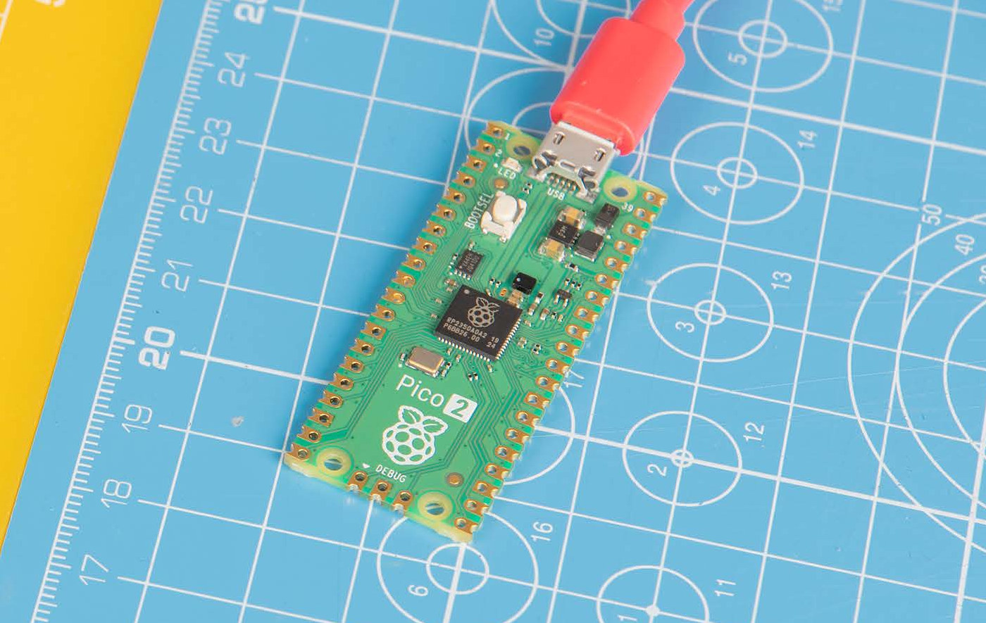
The Raspberry Pi Pico 2 is an MCU development board based on the new Raspberry Pi RP2350 dual-core RISC-V or dual-core Cortex-M33 microcontroller with 520
 honest jolt
520 kb of RAM and 4 MB flash is rivaling ESP32 processors!
still no reset button though lol
strong flame
Still no Type-C..
hard estuary
I'll wait for the feather so I can have type-c. 🙂
honest jolt
there's also an A and B version, hopefully someone breaks out the B version for all those extra pins
strong flame
12 PIO!
hard estuary
LadyAda just had a livestream, said she wants to make a new Metro with the B version for those extra pins
late fulcrum
Still no built-in DAC...
I get it, though: it's tough to build a mixed-process chip that cheaply
hasty quarry
vestal pier
how about just proportional to total linear movement of the CNC tool?
That’s an interesting idea
thick wind
Woah, that’s not bad at all for the price. There’s even some security features now.
If they do come up with a cheap 24xx I hope they’ll add a DAC and a better ADC peripheral, but that’s probably a ways out.
vestal pier
I don't get the dual Cortex OR dual Risc-V cores. Are they different SKUs, or do you have both sets in each chip and somehow choose what you're using?
thick wind
vestal pier
I don't get the dual Cortex OR dual Risc-V cores. Are they different SKUs, or do...
The latter.

Wonder what bonus functions we can milk the third PIO for…
On that note, does anyone know what an HSTX port is? The feather rp2350 mentions it but I’ve never heard of it before?
 viscid folio
High Speed Transmission - for DVI and other high speed outputs
(itll be in the datasheet)
late fulcrum
vestal pier
I don't get the dual Cortex OR dual Risc-V cores. Are they different SKUs, or do...
Chips have both, and there are various boot flags to enable/disable architectures, as well as ways to enable both and have the code switch (with a default to start with)
vestal pier
nifty, thanks guys!
thick wind
Oh, there is an FPU.
vestal pier
yeah, noticed that
thick wind
And they claim to have fixed the nonlinearity issue in the 2040 adcs
dusty citrus
somber spindle
As long as the oxidization is just surface level, you should just be able to hea...
Retin, by itself or with a other compound?
@late fulcrum they cost more or less like a new tip...
glad ruin
strong flame
||RISC-V coproccccc||
It is not a coprocessor. They don't run simultaneously.
At this point I've fully lost faith in RPF and RPi LLC. I avoided the Pi 4 because of its terrible power design. I wasn't happy with the direction they took the Pi 5 with its 5A @ 5V requirement. Then they proved that they were trend-chasing by introducing an "AI accelerator". They have a long history of questionable design decisions. I'm not surprised by what they've done with the RP2350. Just disappointed.
strong flame
glad ruin
It is *not* a coprocessor. They don't run simultaneously.
yea I said that before I read the datasheet, it's like the riscv duo kinda
late fulcrum
dusty citrus
Retin, by itself or with a other compound?
<@348911944486486016> they cost more ...
The tinning compound does cost some, but can be used over and over (I've been on the same tin of it for 15 or so years)
 urban arrow
So glad for TheLady and Phil in new digs and back in business!
Placed an order this morning, and got the shipped email 1 hour and 9 minutes later.
😀 😀
 median viper
@late fulcrum hey guy I am up in NY for the week, in Rochester, I am learning about RISC-V, do you know any RISC-V SoC systems that are affordable?
late fulcrum
I imagine there are, but it's not something I've looked in to.
median viper
late fulcrum
I imagine there are, but it's not something I've looked in to.
I heard a a speech from the Linux foundation they are going to support it because there is no licensing fees so it's a general computing standard, it's just that the computer seems rather pricey right now
I will look around
dusty citrus
median viper
I heard a a speech from the Linux foundation they are going to support it becaus...
From press there was some milk V board around there
I can't say how better are they thought, maybe it makes sense if you're designing your ic, for consumer they all come in a similar price-format featurewise
Heh looking around there are tons of fiber cabinets that are open up, maybe it makes more sense to use some kind of splitter to borrow some free internet /s
median viper
dusty citrus
From press there was some milk V board around there
I can't say how better are ...
Well unlike ARM doesn't charge royalty
 dreamy furnace
Can someone please help me 😭
So I just got a new mac for coding and literally no code is working.
This is my code:
import board
import neopixel
import digitalio
pixels = neopixel.NeoPixel(board.NEOPIXEL, 10, brightness = 1)
colorlight = (85, 166, 237)
while True:
pixels.fill((colorlight))
simple right?
but then i get errors like this
Traceback (most recent call last):
File "code.py", line 48, in <module>
File "neopixel.py", line 141, in __init
ValueError: NEOPIXEL in use
I've tried everything
 glacial wigeon
glad ruin
It is *not* a coprocessor. They don't run simultaneously.
glacial wigeon
glad ruin
It is *not* a coprocessor. They don't run simultaneously.
from what i can see, they can run simultaneously
the chip has 2 arm, and 2 risc-v cores
and you must pick exactly 2 of them to be active
that does allow arm+risc-v, but then you cant share code between them, which complicates your firmware
glad ruin
Yeah, it's kinda odd.
glacial wigeon
currently going over the entire datasheet, the address translation, tmds, and anti-rollback all look useful to solve various limits ive seen before
 tardy badger
Nothing like a new chip dropping to get you back in the PCB Design saddle. (progress so far)
 patent hemlock
talk about not waiting until the paint's dry... 😏
tardy badger
Not super sure what I want to do with this yet. The goal is to break out to two rows of 0.1" headers, add a 22 pin FPC connector, some sensors.. PSRAM, not sure whatelse yet.
Oh I did see some new Bosch sensors that came out that I might try too.
 errant willow
I’m looking for some answers regarding a project that I’ve recently taken up. It appears to be outdated and runs on a Pi2/3. I was curious if anyone knows whether the project has been updated recently. If anyone has any advice or directions, that would be greatly appreciated.
late fulcrum
It's Python code, should be pretty portable. It seems to depend on pygame, which may well be installable on other Pi boards.
tardy badger
ah yeah, it's starting to look pretty neat now.
 late fulcrum
tardy badger
ah yeah, it's starting to look pretty neat now.
late fulcrum
tardy badger
ah yeah, it's starting to look pretty neat now.
I'm guessing you're going for the integrated flash version? I couldn't find prices on the individual chips.
I'm guessing the orientation of the chip relative to the USB connector is largely determined by the USB data pins. It looks like you might be able to rotate it 45° widdershins and then shove the inductor a little farther away from the USB signals.
quartz marsh
tardy badger
ah yeah, it's starting to look pretty neat now.
Surely you add USBLC6-2P6 ESD protection on the USB-C port
quartz marsh
tardy badger
ah yeah, it's starting to look pretty neat now.
Or did you already use individual TVS diodes
quartz marsh
tardy badger
ah yeah, it's starting to look pretty neat now.
Very cool btw, is this like a compute module which you're going to stack add-ons on top of?
late fulcrum
I tend to see two schools of thought on capacitors. Some designers like to put them parallel to the edges (for shortest traces) and run signals around and under them, others like to put them perpendicular to displace other traces the least. You seem to be the latter type. From the vias, I'm guessing this is a 4-layer board.
quartz marsh
tardy badger
ah yeah, it's starting to look pretty neat now.
this would be a good way to do it for this design
 quartz marsh
late fulcrum
I tend to see two schools of thought on capacitors. Some designers like to put ...
quartz marsh
late fulcrum
I tend to see two schools of thought on capacitors. Some designers like to put ...
It would have to be 4-layer for high speed signals like USB and the crystal I would assume
late fulcrum
Nice guard ring around the crystal
tardy badger
late fulcrum
I'm guessing the orientation of the chip relative to the USB connector is largel...
If you look in the reference design, they actually put their inductor pretty close. But they also use a much smaller custom packaged inductor so that helps too. My choice is a "best guess for right now" until their custom one is available.
tardy badger
quartz marsh
Surely you add USBLC6-2P6 ESD protection on the USB-C port
I might, I haven't gotten that far yet. I'm just getting the basics laid out before adding anything else. Being a USB 1.1 PHY, ESD protection isn't super critical.
tardy badger
quartz marsh
Very cool btw, is this like a compute module which you're going to stack add-ons...
That's the the plan yes.
thick wind
I don’t think 4-layer is a hard requirement for anything under 100MHz?
tardy badger
Here's from the hardware design doc
 tardy badger
thick wind
I don’t think 4-layer is a hard requirement for anything under 100MHz?
tardy badger
thick wind
I don’t think 4-layer is a hard requirement for anything under 100MHz?
it's not. though 4 layers is pretty cheap these days so might as well spring for it
thick wind
It’s a good price for dev-board-sized devices for sure.
thick wind
I’ll probably try to use 2-layers for my larger stuff still.
tardy badger
I'd only consider 4 layers if I was planning to really push the HSTX bus
which.. I might..
thick wind
I’m thinking to myself why upgrade unless I use it
But then I can’t find a use for it myself so ehhhh
tardy badger
The mezzanine connectors are sort of a first thought of "I wonder how this would fair with an FPGA partner" and the HSTX bus would provide a really fun interconnect to an FPGA
sure, just TX but you can probably push the 3 PIO for RX backwards
thick wind
This thing would be fun to pair with an fpga, wouldn’t it…
Like a miniature cpu/gpu combination
tardy badger
Yeah, I thought maybe it would be fun to put something like a CrossLink-NX or Certus-NX on the other end of the HSTX bus, drive a display with images from a camera connected to the RP235x
thick wind
There's enough pins and an FPU, time to build a 3D printer based on one of these.
tardy badger
hehe yeah
I'm excited about the SecureBoot ROM
and the fact that it's open source too
glacial wigeon
tardy badger
I'd only consider 4 layers if I was planning to really push the HSTX bus
i'm wondering, can HSTX do CSI and DSI?
tardy badger
no, but you can do DVI
though technically speaking.. you should just be able to send about anything
it is a DDR interface though so up to 300mbps sounds promising
jagged citrus
I saw raspberry pis being used at a supermarket
 tardy badger
late fulcrum
I'm guessing you're going for the integrated flash version? I couldn't find pri...
tardy badger
late fulcrum
I'm guessing you're going for the integrated flash version? I couldn't find pri...
I was thinking about it. I really like the idea of having integrated flash and just using the main qspi port for PSRAM or additional flash.
vestal pier
are there any chips that use qspi for high speed internet?
tardy badger
maybe?
tardy badger
vestal pier
are there any chips that use qspi for high speed internet?
has QSPI support
tardy badger
Just need some buttons for boot/reset. maybe some LEDs. SWD debugging port. pretty close to being done.

 fringe swan
Looking for a thread for help with the hallowing m4. I dont think there is one. Which help thread is appropriate?
hard estuary
fringe swan
Looking for a thread for help with the hallowing m4. I dont think there is one. ...
It might depend how you're programming it, there's #help-with-circuitpython or #help-with-arduino or #help-with-projects is more of a catch-all
tardy badger
One more set of headers to go, and a little silk screen
 tardy badger
and it's done.
 ebon dew
tardy badger
and it's done.
ebon dew
tardy badger
and it's done.
Looking really good! What are the primary and secondary chips? What kind of GPIO connectors are those?
They remind me of the tiny ones inside a smart phone.
tardy badger
ebon dew
Looking really good! What are the primary and secondary chips? What kind of GP...
Primary QSPI Flash and a secondary QSPI Flash that can be used as well 🙂
the connectors are a kind of HIROSE mezzanine connector
tardy badger
It was requested that a stemma QT/QWIIC connector was added lol

hand the wrong JST connector for stemma lol...

 stuck moth
tardy badger
Primary QSPI Flash and a secondary QSPI Flash that can be used as well 🙂
stuck moth
tardy badger
Primary QSPI Flash and a secondary QSPI Flash that can be used as well 🙂
You may want the secondary to be PSRAM instead of flash
tardy badger
yeah, that too
vestal pier
what's SW1 for?
tardy badger
turning on and off the 3.3V regulator
weary fiber
Recently discovered uPNPwizard and I'm in love
no more plex port forwarding issues while I'm stuck without access to router settings
thick wind
tardy badger
It was requested that a stemma QT/QWIIC connector was added lol
Does that crystal interfere with the StemmaQT connector? Would a vertical connector fit better there?
tardy badger
It shouldn't
thick wind
Oh it was changed in the second pic nvm
tardy badger
no worries 🙂
what a fun board to design though
Imagine being cool enough to get to be a design partner like Solder Party, or get early access to the Pico 2
Too bad it's going to be a bit before I can build it. I don't think i'd be able to get samples like I did with the RP2040
I kind of want to redo my RP2040 watch with the RP2354-A. better low power mode and TrustZone are pretty nice features to have in a mobile chip.
glacial wigeon
tardy badger
no, but you can do DVI
i got a schematic from somebody else, that uses a tangled web of resistors and 3 gpio, to emit CSI from dumb digital pins on an fpga
it uses 2 pins with one set of dividers, to create the differential high speed signal at low voltages (HSTX can take this role)
and then 1 pin with a different divider, to create the single-ended low-speed signals
tardy badger
You could probably figure out a way to fake it out. It won't be very fast though. MIPI for CSI is usually pretty quick.
glacial wigeon
you would be limited to 150mhz ddr if you dont overclock, but 2 lanes is enough to meet my bandwidth needs
tardy badger
When you get your hands an an RP2350, definitely let me know how that goes for you. I'd be curious to see what happens
tardy badger
My RP235X-B Evaluation board if anyone is interested
https://github.com/Oak-Development-Technologies/RP235X-B-Evaluator

GitHub
Open source repository for storing the files for the RP235X-B Evaluator, an RP235X-B Evaluation board. - Oak-Development-Technologies/RP235X-B-Evaluator
glacial wigeon
tardy badger
When you get your hands an an RP2350, definitely let me know how that goes for y...
this can turn 4 1.8v gpio from an fpga, into a differential signal that can move 600mbit into an rpi

so in theory, you can just rig up a pico (1 or 2), with 1.8v io
the LP pins would be PIO for the low-speed stuff
the HS pins would benefit from HSTX (half the clock needed), but PIO might work?
 full spade
Hey everyone
tardy badger
glacial wigeon
so in theory, you can just rig up a pico (1 or 2), with 1.8v io
the LP pins woul...
PIO should, you could in theory drive stuff pretty quickly from it since it's independent of the CPU.
glacial wigeon
also, using the new random access stuff in rp2350 pio, you can store the length controls into the "rx fifo"
rather then having to put the length as the first word on the tx fifo
so you can program a length into 2 SM's, the LP SM can emit the startup, the HS SM can then emit the sync and packet, and then the LP SM can finish the packet off
and use some inter-SM IRQ to sync them all together
and tri-state the pins as you pass roles
in theory, this can also drive a DSI display, just load different packets into the FIFO
so you dont have to keep tip-toeing around "its not hdmi", lol
tardy badger
lol yeah, that seems like it'd be a good option to try out
 proud otter
weird vga male wire that can be plugged into a phone *shocking*

and its a charger
*shockest*
round minnow
VGA is really DB-15. (generic) DB-15 can be used for other things as well. That image does not look quite like DB-15, even it it fits in a VGA connector.
 whole jacinth
although DE-15 resembles that image, the pin count is different. the image shows an 11-pin connector. (VGA is DE-15, not DB-15)
 gloomy blaze
Is the pygamer anywhere in stock?
jagged citrus
THERES A PI PICO 2?!?!?!?
ebon dew

It's twice as fast with more ram and more goodies. Same footprint so you can drop it in projects that were using a Pi Pico 1.
jagged citrus
Niice
late fulcrum
jagged citrus
THERES A PI PICO 2?!?!?!?
Soon...
hard halo
I don't like reading books like this -> https://www.feynmanlectures.caltech.edu/
I think it's terrible reading online or in the PC
I like the paper book, otherwise I will not read :/ I would really like to change this, cause I've read maybe about 50 books my entire life, and no PC books
and I have like 15 billion dollars worth books online for free in the internet
It's like I'm like rich and not using my money 😦 😦 😦
proud otter
round minnow
VGA is really DB-15. (generic) DB-15 can be used for other things as well. That ...
so then a wannabe vga male port
dusty citrus
Anyone knows anything like
https://www.impulse-embedded.co.uk/products/d/amd-ryzen-embedded-sbcs.htm
But with actually pricing that's not down to pointless inquiries?
Ultra-reliable AMD Ryzen Embedded SBCs (SBC) from Impulse with long-lifetime supply and revision control. Available in 2.5", Pico-ITX, 3.5", PC/104 and EPIC form factors, suitable for a wide range of embedded OEM applications.
glad ruin

fun electrical engineering facts:
electricity flows fastest on red pcbs
blue pcbs have the best thermals
green pcbs are the most energy efficient
purple pcbs taste the best
patent hemlock
i just want to know who is licking these boards.... "taste"? really?
dusty citrus
...nintendo maybe
 patent folio
Nice, somebody's been enjoying the projects on T-Deck...https://www.lilygo.cc/products/t-deck-plus

LILYGO®
Upgraded based on T-Deck, mainly added GPS module, and 2000 mAh battery Specifications MCU ESP32-S3FN16R8 Dual-core LX7 microprocessor Wireless Connectivity 2.4 GHz Wi-Fi & Bluetooth 5 (LE) Development Arduino, PlatformlO-IDE, Micropython Flash 16MB PSRAM 8MB Battery ADC PIN IO04 Onboard functions GPS,TF Card,Micr
hard halo
https://www.youtube.com/watch?v=-kFOXP026eE&list=PLS3_1JNX8dEh5YcO-Y05stU0u_T9nqIlF Richard Feynman jokes were the best 16:11 😅
 hard halo
physics teaching at university changed a lot from his time to today
patent hemlock
physics has changed a bit, too 😀
hard halo
They pay so much attention in equations that forget how important are explainning them profoundly so you can understand why each term is in there, things like this were lost :/
hard halo
patent hemlock
_physics_ has changed a bit, too 😀
Modern Physics is a separate class at university, this is Physics 1 basically, Physics 1 teaching changed a lot
patent hemlock
i will have to take your word for it (i was closer to his day than today's courses 😈 )
dusty citrus
some kind of mechanical sensor that can detect a fall, without any electronic component, that when "activated" makes a linear motion? I did quick sketch of a possible solution, I dunno if it would work, but surely if the fall goes aganist the red wall it would not work on that direction, unless I add a second pair.. anyone has any other idea?
 dusty citrus
or a crank....
late fulcrum
Some sort of spring loaded pendulum that's centered and extended while exposed to gravity but retracts when in free fall?
stiff brook
so I am looking to use a feather board with stemmicq but I need a board with eeprom on it so we can store default settings and settings changes
is there one ?
 fossil dawn
stiff brook
is there one ?
fossil dawn
stiff brook
is there one ?
On RP2040 you have emulated eeprom. It uses a small portion of the program memory flash. Disadvantage: amount of times you can write to it depends on what flash adafruit uses but it's still more than enough for something like settings.
Similar libraries (that are even more advanced I think) exist for esp32. (I think it's called "preferences" library for esp32)
stiff brook
yes but as this is a radio projet and has to have a long lifespan O would like to use eeprom
nvm wears out faster
fossil dawn
Check the datasheet and calculate
The preferences (?) library on esp32 even does some wear leveling
stiff brook
you have to save settings on any change like freq channel mem storage and such so it would wear out faster
hmm so a esp32 feather might be better ?
ok or I could put a i2c eeprom on our cntrol board also
hmm . have to keep cost down
fossil dawn
The flash on the rp2040 feather still has "min. 100k erase cycles per sector"
stiff brook
ok
fossil dawn
I think there's an atmega328 feather with eeprom but then you have an atmega328 xD
stiff brook
and I think its 64k right
the issue I find with nvm is you have to rewrite all the settings every time with eeprom you can write just what changes
as I recall
fossil dawn
stiff brook
the issue I find with nvm is you have to rewrite all the settings every time wit...
Preferences library on esp32 takes care of that for you
Not sure how the emulated eeprom library on rp2040 arduino-pico works
stiff brook
so which of the esp32 feathers s best
night crescent
LIVE FROM BROOKLYN! Desk of Ladyada https://youtu.be/1Q7oOinZHQI

Exciting news from Ladyada's desk! After a big move, we're settling into our spacious Brooklyn lab. On deck: Rev B of the Vindie board & testing new RP2350 designs! The Feather RP2350 & Metro RP2350 promise extra GPIO & innovative features.
stiff brook
wow hour late
hard halo
dusty citrus
some kind of mechanical sensor that can detect a fall, without any electronic co...
I am 4h thinking about this and I could not think of anything
but why not use an eletronic component? Is it more profitable?
ebon dew
@stray harbor Adafruit is the only supplier of the Memento enclosure kit to my knowledge. If it's out of stock it's out of stock. 😦
3D files are usually in a products accompanying learn guide https://learn.adafruit.com/adafruit-memento-camera-board/downloads If they are available they will be in the downloads section of a product learn guide.
 stray harbor
ebon dew
<@473584917054357525> Adafruit is the only supplier of the Memento enclosure kit...
stray harbor
ebon dew
<@473584917054357525> Adafruit is the only supplier of the Memento enclosure kit...
Thanks
dusty citrus
hard halo
but why not use an eletronic component? Is it more profitable?
I should order and wait for parts, while if I can just 3d print it why not
night crescent
🐍🎉 THIS Friday - August 16, 2024 - CIRCUITPYTHON DAY! 🐍🎉
https://adafruit.com/circuitpythonday2024
https://circuitpython.org
Join the community of creators, hackers, educators, and more - celebrating python on hardware! The easiest way to program microcontrollers!
11am 3D Hangouts with Noe & Pedro
1pm Maker Chat: Guy Dupont
2pm CircuitPython Project Highlights with Paul Cutler & Tod Kurt
4pm JP’s Workshop
5pm Deep Dive with Scott
6pm CircuitPython Game Jam with Tim
Ladyada is doing a special event during the day (stay tuned for the time), AND there will be discounts at Adafruit, ALL DAY!

Adafruit Industries - Makers, hackers, artists, designers and engineers!
It’s that time of year! Adafruit has determined that August 16, 2024 is the snakiest day of the year and designated it CircuitPython Day! Adafruit will have special shows and more (all times …

The easiest way to program microcontrollers
night crescent
night crescent
🐍🎉 THIS Friday - August 16, 2024 - CIRCUITPYTHON DAY! 🐍🎉
https://adafruit.c...
 orchid saffron
jagged citrus
orchid saffron
jagged citrus
woah nice! luckfox boards and milkv now have blinka support

and mine just arrived today
 solemn sierra
i was curious on the average time before orders start shipping?
ebon dew
solemn sierra
i was curious on the average time before orders start shipping?
I just ordered something last week and it shipped within a day or two and arrived within 5 days. In total from time of order to time of arrival is typically about 5-7 days depending on where you live in the US and the shipping option you choose. The closer you live to NY the faster you'll receive your package.
If anything... Adafruit's shipping department is now a little faster at the new location. I ordered regular USPS ground shipping and it got to Florida in 3 days when it would typically take about 7-8 days. Because I order a lot of stuff I can tell the shipping at the new location is a little more efficient. I have no idea what their shipping dept looks like or what changes were made at the new location. I'm just a regular customer and noticed it was actually a little faster than usual.
brittle condor
please someone help me understand this right, cause i'm really struggling here...
I'm trying to write firmware for a smart plug which has a BL0937 chip to measure power, voltage and current
datasheet: https://www.belling.com.cn/media/file_object/bel_product/BL0937/datasheet/BL0937_V1.02_en.pdf
according to the datasheet the frequency is calculated as F=V/V_ref*15397 which would give a frequency of 2.9Mhz, wouldn't that be a bit excessive to be able to measure it with a typical micro controller?
the math for the power frequency comes out to 266MHz.... that is quite high...
like, i've tried implementing it with triggers, but it just crashes my esp8266 and reboots it constantly...
thick wind
brittle condor
please someone help me understand this right, cause i'm really struggling here.....
The circuit in the typical application uses a rather large voltage divider to sample the voltage. 1980:1 ratio should bring a 240Vac wave down to around 120mVac, or a 1.45kHz pulse output.
If you did hook your line voltage directly to the voltage input terminal of the chip, I’d consider the possibility of the chip being fried and get a new one.
If you’re hacking an existing plug, you should measure the resistances in that voltage divider.
brittle condor
it's an already existing product, I'm just replacing the microcontroller with my own
the existing plug has 3 480k resistors in place of the 6 330k from the reference circuit, and the 1k resistor is unchanged
thick wind
For best results, measure the resistance with a meter. This helps avoid any discrepancies in resistor tolerances and saves you some trouble in doing the math twice.
But assuming 480k X 3 = 1.44M, a 240Vac input will step down to around 166mVac, a much more reasonable frequency to measure.
With a fixed 38us pulse width, your frequency limit is around 26kHz anyways. However, this allows you to push this signal through a low-pass filter and measure an analog voltage instead of a frequency measurement.
brittle condor
I've measured a couple of loads and periods, this is what I've got
12w --> 144000uS
50w --> 52300uS
how should i convert the period into wattage?
thick wind
Have you tried the power formula? @brittle condor
 brittle condor
well, inverting that formula would give me the "equivalent power consumption" since it's scaled down by the resistor divider, right?
thick wind
To my understanding, that would be correct.
brittle condor
how would i go back to the real power consumption then?
thick wind
Multiply by the voltage divider ratio.
Current should also have some conversion, you’ll have to measure those resistances and figure that out as well.
For the shunt resistor, hopefully there is a marking because most multimeters won’t be able to read that reaistance accurately.
thick wind
Then you should be close enough with just the voltage divider ratio.
To the best of my knowledge anyways.
brittle condor
alright, i guess I'll try it now
brittle condor
ok, fun development, i just did the full math, and the value of the constant that i calculated by deducing from the measured values was actualy very close to the valye i got from the math lol
my value was 1800000, the calculated value is 1814230 lol
issue is... the calculate values are wrong...
like, it's the right order of magnitude, but it's the wrong actual value
i fear that might just be my bad code...
ok so, just to make sure, i used my other two smart plugs to check the power usage and indeed my power meeter is correct, my lightbulb does comsume 12w
so now i wonder why my code is measuring 9...
 barren perch

Attaché : 1 image
@adafruit@mastodon.cloud "ALERT! ALERT! THE DOCTOR HAS BEEN DETECTED!"

 tranquil swallow
Indeed, there goes my page
thick wind
brittle condor
so now i wonder why my code is measuring 9...
I believe the power measurement is just a product of the voltage and current readings. I'd check the accuracy of the voltage reading first, then test your plugs with a different load to see if the error is proportional or offset.
night crescent
SHOW and TELL 8/14/2024 https://youtu.be/77yRMD3ZO-M
 glad ruin
jagged citrus
glad ruin
jagged citrus
 jagged citrus
glad ruin
https://cdn.discordapp.com/attachments/923433336163151913/1273422488747114619/Un...
jagged citrus
glad ruin
https://cdn.discordapp.com/attachments/923433336163151913/1273422488747114619/Un...
what is this creature
glad ruin
I'm pretty sure it's Whinnie the Pooh.
jagged citrus
pink unicorn
 night crescent
ASK AN ENGINEER 8/14/2024 LIVE! https://youtu.be/6yzP2oDYrvc

ASK AN ENGINEER 8/14/2024 LIVE!
Visit the Adafruit shop online - http://www.adafruit.com
LIVE CHAT IS HERE! http://adafru.it/discord
Subscribe to Adafruit on YouTube: http://adafru.it/subscribe
New tutorials on the Adafruit Learning System: http://learn.adafruit.com/
-----------------------------------...
 brave copper
Can the SoundFX be power by two AAA batteries? - what's the operating Voltage I need?
brittle condor
thick wind
I believe the power measurement is just a product of the voltage and current rea...
i realized that i flipped the pins for the power and the current/voltage measurement, so what i was actually measuring was the current (both active and reactive) and since my two test loads had different power factors it would give different results depending on the load. Flipped the pins and now i've resoluted to just trying different values for the constant i have to divide by, I've got 3 other power meters that agree on both power and voltage measurement so i'm trying to get as close as possible to those values....
question, is it a bad idea to attach and detach interrupts constantly on an esp8266?
i've noticed that since implementing interrupts to measure power in my project, my esp8266 gets quite a lot warmer, so i'm worried i'm kinda overloading it, and perhaps disabling measuring current and voltage constantly and doing it only once in a while would be better. opinions?
late fulcrum
brave copper
Can the SoundFX be power by two AAA batteries? - what's the operating Voltage I ...
It's a little complicated because the chip has on-board regulators. The input voltage needs to be at least 0.3V above AVDD, but AVDD is programmable between 2.6 and 3.6V. So if your AA cells provide (say) 3.0V, and you set AVDD to 2.6V, it would give you 100mV of headroom. Note that the breakout board also contains isolation diodes which introduce their own voltage drop.
 ancient rivet
brave copper
Can the SoundFX be power by two AAA batteries? - what's the operating Voltage I ...
ancient rivet
brave copper
Can the SoundFX be power by two AAA batteries? - what's the operating Voltage I ...
3xAAA is the recommendation. more info here:
https://learn.adafruit.com/adafruit-audio-fx-sound-board/powering-it
brave copper
the ecto goggles inly uses 2 AAA which is 3 volts and I'll be using two buttons on it red is the flash charge sound and the bottom can be the cmaera shutter sound
late fulcrum
On the one hand, you might get away with it if you programmed the voltage regulators to 2.6V and bypassed the series diode and your battery stays near its nominal voltage. On the other hand, you could just try it and see. On the gripping hand, you could use a voltage booster.
brave copper
3v should be good enough for two basic sounds
 ruby pasture
Has anyone worked with custom fonts on an ST7789 SPI Display? I'm using an ESP32 with an ST7789 SPI display. My goal is to input a word through the serial monitor, have it translated to another language (Sinhala) using the Google Translate API, and then display it on the TFT screen. However, my custom font isn't displaying correctly because the response is in UTF-8 format. I need to convert this format to Unicode to work with my custom font. Ultimately, I need to convert the Google Translate API response to Unicode. How can I achieve this? Has anyone done this before?
late fulcrum
UTF-8 is Unicode.
ruby pasture
late fulcrum
UTF-8 is Unicode.
🧐
ruby pasture
late fulcrum
UTF-8 is Unicode.
I need to convert UTF-8 format to Unicode to get a response from Unicode.
late fulcrum
Again, UTF-8 is Unicode. Do you need to convert it to UTF-32 to index into font tables, perhaps?
Or more specifically what encoding does your custom font use?
ruby pasture
late fulcrum
Again, UTF-8 is Unicode. Do you need to convert it to UTF-32 to index into font...
I have a custom font. When I insert a normal meaningful unicode (English word to Sinhala word and I got the Unicode of Sinhala word) it correctly shows on display using that custom font. So I think the Google Translate API response is not in unicode format. So I should convert that response to Unicode. Then put that final unicode response to print on display.
late fulcrum
It sounds like you're saying Roman characters (such as "U") appear in your font at the same address as their Unicode representation. For such characters, this is fairly trivial, as a Roman "U" is 0x55 in UTF-8, and it is 0x0055 in UTF-16. It's a little more complicated with a Sinhala character such as "යා" (yayanna). In UTF-16, it's 0x0dba. But in UTF-8, it's represented as 3 bytes: 0xe0 0xb6 0xba.
So if it's present in your font at offset 0x0dba, you'd just need to convert UTF-8 to UTF-16. There are two ways to do this.
There's the simple way, which just looks at the bits and assembles them accordingly. Then there's the fully fleshed out complete way, accounting for surrogate characters, continuation bits, and all the other complexity that Unicode supports. I'm guessing the simple way is sufficient for your purposes (although there are some ligature issues that might crop up)
late fulcrum
I dashed off a quick example in C of the simple conversion from UTF-8 to UTF-16: ```c
for (uint8_t * bptr = text; *bptr != '\0'; ++bptr) {
if ((*bptr & 0x80) == 0x00) {
// 1 byte sequence
process(*bptr);
} else if ((*bptr & 0xc0) == 0xc0) {
// 2 or 3 byte sequence
code = 0;
        if ((*bptr & 0xf0) == 0xe0) {
            // 3 byte sequence
            code |= (*bptr & 0x0f) << 12;
            ++bptr;
        }

        code |= (*bptr & 0x3f) << 6;
        ++bptr;
        process(code | (*bptr & 0x3f));
    }
}
For the complete approach: https://github.com/Davipb/utf8-utf16-converter/blob/master/converter/src/converter.c
 fierce torrent
Is there an appropriate space or channel for questions on the adafruit_midi library and messages ? Thanks
hard estuary
fierce torrent
Is there an appropriate space or channel for questions on the adafruit_midi lib...
I would ask in #help-with-circuitpython as it's a CircuitPython library
fierce torrent
thanks Paul
 chrome oasis
Hi, does anyone know what the best website to get an acrylic piece cut and engraved to any shape? Specifically one where you don’t have to make a quote - one specifically designed for making one or two items. It should also preferably be in the UK - I need this quickly, before the end of next week. Sorry if it’s too specific!
late fulcrum
I usually use Pololu, SendCutSend, or Ponoko, but I'm in the US.
It looks like Ponoko has a UK presence: https://www.ponoko.com/blog/ponoko/now-you-can-make-in-the-uk/

Local shipping saves you money London-based RazorLAB is the latest fabber to launch an independent making hub using Ponoko. It means, from today, you have access to local making and shipping rates in the UK through your Ponoko personal factory. Your making project in good hands “We love laser. We laser love!” says RazorLAB CEO Soner Ozenc. “We a...
dusty citrus
I'm doing some pretty 💩 work here, but I can't get out the solder of the two first shorted pins, it seems like it's stuck on the soldermask, I can't hear it up correctly, the pump doesn't reach there, nor copper fibers seem to work
Nvm solved with a ton of paste
 chrome oasis
I saw that on the Learn guide for the Qt Py SAMD21, and it says this about the 5V pin: "This is 5v out from the USB port. You can also use this as a voltage input but you must have some sort of diode (schottky, signal, power, really anything) between your external power source and this pin with anode to battery, cathode to 5V pin." Why is this? Do you absolutely need a diode or will it break otherwise? Is it just to protect the USB port or something? (because i'm making a battery powered project which won't ever be plugged into usb at the same time as the batteries being live, so if it's just to prevent too much voltage being fed into the usb port of the computer, it should be fine.)
The reason why I don't just buy some is that I found this out after I ordered my parts -_-
late fulcrum
You have the right idea: the idea is to protect the computer and circuitry if the USB and another source are connected at the same time. It's all to easy to forget just once and destroy your computer (ask me how I know)
chrome oasis
Luckily the project is super simple and shouldn't take long to do
So I'll add the battery afterward
chrome oasis
would 3 AA batteries even be enough to destroy my computer?
thick wind
dusty citrus
I'm doing some pretty 💩 work here, but I can't get out the solder of the two fi...
For future issues like this, the key is to add flux, which will help the solder flow when it melts. I’d also recommend learning to use an iron and solid solder for through hole soldering, as excess paste often ends up leaving a lot more of the small solder balls all over your board. If they get loose, they could do bad things for your circuit.
late fulcrum
chrome oasis
would 3 AA batteries even be enough to destroy my computer?
3 AA cells is around 4.5V (or less if they're NiMH). Without the diode, they'll try to drag down the 5V USB supply voltage to their voltage, drawing significant current in the process. What happens next depends on your computer. Many computers have a polyfuse or current sensing in their USB ports and will shut off the port due to excessive current draw. However, some computers lack these protections and could suffer damage.
fair summit
chrome oasis
So I'll add the battery afterward
if the battery doesn't have to be internal, you could also just use a USB power bank. Note that some shut off if the current draw is too low. Some can override this: Voltaic Systems will, and at least some Anker power bnaks let you push a button to get it into a low-current mode.
chrome oasis
late fulcrum
3 AA cells is around 4.5V (or less if they're NiMH). Without the diode, they'll...
i'm using a modern laptop made in the last 5 years, its not cheap so i can imagine they would put good usbs in
but still, i'll probably add a physical thing on top of the usb that reminds you to NOT CONNECT THE BATTERIES AT THE SAME TIME
itll be an internal usb, the end user wont be able to access it
fair summit
chrome oasis
itll be an internal usb, the end user wont be able to access it
If you make another project like this, you can consider the Feather boards, which have a built-in battery charger. Or you could add this to the current project: https://www.adafruit.com/product/5397
Is your QT Py all alone, lacking a friend to travel the wide world with? When you were a kid you may have learned about the "buddy" system, well this product is kinda like that! A ...
night crescent
BIG SALE TODAY!
https://adafruit.com
16% OFF SALE! CODE: CPD16
TODAY ONLY 8/16 12:00 AM EDT through 8/16 11:59 PM EDT
*SOME EXCLUSIONS MAY APPLY
*WHILE SUPPLIES LAST!

Adafruit Industries, Unique & fun DIY electronics and kits : - Tools Gift Certificates Arduino Cables Sensors LEDs Books Breakout Boards Power EL Wire/Tape/Panel Components & Parts LCDs & Displays Wearables Prototyping Raspberry Pi Wireless Young Engineers 3D printing NeoPixels Kits & Projects Robotics & CNC Accessories Cosplay/Costuming Hallow...
dusty citrus
thick wind
For future issues like this, the key is to add flux, which will help the solder ...
Maybe is that it's a while that I don't solder pins, but I never had this sort of problem, the blue board is the absolute garbage that I got... At desidering I was always bad, I guess I call it a day.. if it works

 thick wind
In that case, either the solder mask layer has been damaged somehow, or the solder mask is just of terrible quality…
 shadow siren
use some liquid flux and the soldering pencil is too cool, turn up the temp. from the pics it looks like cold solder joints
are you using 60/40 lead solder or lead free, if lead free then you need a different pencil temp to make the solder flow.
dusty citrus
shadow siren
use some liquid flux and the soldering pencil is too cool, turn up the temp. fro...
The temp of the iron was setted at 450C although from the display it reaches only 400C...
As for solder/flux random stuff from ali, I dunno if I used it elsewhe, going to try with random pegboards and pins and see how it goes

On the blue board I can't heat up the pins, when I put solder in it doesn't stick, and if it does I can't get it out easily
late fulcrum
That solder might be terrible
shadow siren
This is 55/45 lead from Ali express

This Lead free same supplier

solder paste has a different melting point and the way it works on boards, not for through hole soldering
dusty citrus
On the "pegboard" it looks fineish
 dusty citrus
shadow siren
solder paste has a different melting point and the way it works on boards, not f...
dusty citrus
shadow siren
solder paste has a different melting point and the way it works on boards, not f...
Any recommendations that does not cost a kidney and could be sourced on Ali?
Weller stuff is pretty expensive
late fulcrum
This is my everyday solder. It's nice and doesn't cost a kidney. Not sure you can get it on Ali.

This is my favourite solder. An absolute joy to use, makes gorgeous shiny joints, it's like a secret weapon. And yes, it costs a kidney.
 dusty citrus
So on the blue board either damaged/bad soldermask/pins?
On the pegboard it doesn't seem too bad... Not that shiny but it's not a blob, and I can heat up the pins and let the solder stick to the th pad
Or maybe I suck, it's also an option
thick wind
I for some reason doubt it’s an issue with the iron or the solder. If the thermal mass of a plane or trace is too high, you may find more success with some preheating of the board.
Protoboards have no traces, so thermal mass of each spot is negligible.
late fulcrum
I'm not sure I agree. I think it is the solder and perhaps the iron (both temperature and tip tinning). It looks like the solder isn't properly liquifying, which is why it's sticking to everything.
shadow siren
This is my flux system and the flux I use. The bottle on the left, marked Weller, is a little squeeze bottle with a needle-like tip for squirting out flux. The flux I use does not need to be cleaned up; it is not a corrosive flux.
 dusty citrus
thick wind
I for some reason doubt it’s an issue with the iron or the solder. If the therma...
dusty citrus
thick wind
I for some reason doubt it’s an issue with the iron or the solder. If the therma...
So if P understood it right, I preheat the board (at what temp?) and then try to solder the pins?
It comes to my mind, that I tried also using hot air, as with the iron I wasn't getting results, but didn't much either
thick wind
Can’t say I have a recommendation on preheat temps, especially for rework. Applying heat across the whole board makes soldering that much easier, but attention to the rest of the components is important.
dusty citrus
late fulcrum
This is my everyday solder. It's nice and doesn't cost a kidney. Not sure you ...
It's 20/30 bucks for 250g 🥹
shadow siren
For the through-hole soldering, you should not need to preheat; from my experience, this is a pencil temp and flux issue, usually when the PCB manufacturer pre-tins the pads. I have had PCBs that could have been pre-tinned better, and I had to pre-flux the joint before applying the solder.
I would just search Aliexpress for a 500g spool of lead .8mm solder like this.
https://vi.aliexpress.com/item/1005005984652524.html?gatewayAdapt=glo2vnm
A spool like this will last a long time
night crescent
Adafruit just passed 777 certified open-source hardware projects! https://certification.oshwa.org/list.html?q=adafruit currently 27.38% of all certified projects!


Easily search a complete list of OSHWA certified open source hardware.
shadow siren
looks like a slot machine
dusty citrus
shadow siren
For the through-hole soldering, you should not need to preheat; from my experien...
So to fix this mess at this point what could I do?
Btw the solder on the blue board struggles to liquify, while on the green it's fine. Preheating at 100C (max temp I can reach on the printer) didn't make a difference
vestal pier
Does the blue board have a ground plane, or other feature that is sucking up all your heat?
night crescent
WE ARE LIVE! CircuitPython Day 2024 chat with Ladyada
https://youtu.be/2aiPvFoRHhE

Join founder and engineer, Limor "Ladyada" Fried for a special CircuitPython Day chat!
CircuitPython Day 2024
https://adafruit.com/circuitpythonday2024
Visit the Adafruit shop online - http://www.adafruit.com
LIVE CHAT IS HERE! http://adafru.it/discord
Subscribe to Adafruit on YouTube: http://adafru.i...
https://adafruit.com
16% OFF SALE! CODE: CPD16
TODAY ONLY 8/16 12:00 AM EDT through 8/16 11:59 PM EDT
*SOME EXCLUSIONS MAY APPLY
*WHILE SUPPLIES LAST!
Adafruit Industries, Unique & fun DIY electronics and kits : - Tools Gift Certificates Arduino Cables Sensors LEDs Books Breakout Boards Power EL Wire/Tape/Panel Components & Parts LCDs & Displays Wearables Prototyping Raspberry Pi Wireless Young Engineers 3D printing NeoPixels Kits & Projects Robotics & CNC Accessories Cosplay/Costuming Hallow...
dusty citrus
vestal pier
Does the blue board have a ground plane, or other feature that is sucking up all...
I don't think? It's an orange pi 2w
stiff brook
have you guys seen the wokwi emulator
I just found out they pico with circuitpython on it
I am emulating my setup as best I can
ebon dew
Yes we have many helpers that use it sometimes to mock up projects to answer questions instead of breaking out a physical board. Wokwi is great. Hope they add support for the new RP2350 too.
late fulcrum
Been playing with Wokwi with a Jumperless breadboard
ebon dew
Even though I completely missed almost all the streams today had a chance to watch them on youtube. @balmy lotus and @hard estuary loved the idea of the year in review. Been a great year for added graphics and audio support. Hope to see you both again next year for another year in review.
hard estuary
ebon dew
Even though I completely missed almost all the streams today had a chance to wat...
Thanks! Glad you enjoyed it
urban arrow
By the way Paul, it was cool to see you in person. You have been so helpful (and patient) with me over the last year or so... Thank you!
hard estuary
urban arrow
By the way Paul, it was cool to see you in person. You have been so helpful (and...
Aw, thanks - appreciate you saying that.
 lament trout
silly Q : just received an order from adafruit, some quantities on packed invoice are in blue, some are in red - anyone know what that means?
 cyan fable
flux ai really good at reverse engineering?
like if i import random schematics or pcb, it will tell what is happening inside?
 ornate kernel
lament trout
silly Q : just received an order from adafruit, some quantities on packed invoic...
ornate kernel
lament trout
silly Q : just received an order from adafruit, some quantities on packed invoic...
I believe quantities in red are flagged so shipper/packer notices.
glad ruin
cyan fable
flux ai really good at reverse engineering?
like if i import random schematics o...
No. Ultimately schematics exist to express design intent. And no amount of glorified autocorrect will be able to help with that.
ornate kernel
I love that my entire order history still exists on adafruit.com. I've shared this a few times but just revised.
First order October 1, 2011
Most recent August 16, 2024
 ornate kernel
After watching Charlyn's projects I was really hoping to get more black led acrylic but the 12" x 12" seems shipping prohibative. (No USPS to CAN)
I had a local sign shop laser cut a 24 neopixel ring size and the "waste" was a perfect fit for the 16 pixel ring.
Perhaps Adafruit could benefit from similar smaller sizes for shipping led acrylic? Worth it?

 rapid geode
just to note, as far as i know, the neopixel rings are nested when made. so the 12? fits in the 16, which fits in the 24,
urban arrow
ornate kernel
I love that my entire order history still exists on adafruit.com. I've shared th...
Cool! My first order was Jan 12, 2012 - a Boarduino kit w/ the chip! 😀
late fulcrum
Mine was April 1, 2008, also a Boarduino, and some bare Boarduino boards, along with a proto shield, motor shield, and TV-B-Gone
I just happen to have a pic of those Boarduinos getting assembled

 keen iris
Anybody can help with what lights these are, needing to replace.


 fast ferry
keen iris
Anybody can help with what lights these are, needing to replace.
fast ferry
keen iris
Anybody can help with what lights these are, needing to replace.
searching the markings, it appears to be a light source for a Eurolite TMH-13 intelligent light, and the marketing materials say it's a CREE 10W white LED. if you need to replace it, looks like you replace the whole board. the board seems to be available from a variety of European retailers.
keen iris
fast ferry
searching the markings, it appears to be a light source for a Eurolite TMH-13 in...
Ok thanks thought so. As the lights just popped off I ordered Neopixel and Dotstar 5050 as a replacement. Guess we will see what happens. Thanks again
fast ferry
pretty sure neither of those will work. the LED isn't an addressable LED, it only has power and ground running to it. addressable LEDs need data signals, they don't do anything with power alone AFAIK.
plus they won't be nearly bright enough to power a lighting instrument.
unless you're using that carrier board standalone for some other project and you want to add a microcontroller.
keen iris
I got what your saying
glad ruin
 wheat peak
is it possible to have FM composite video output with 10 KHz of bandwidth
wheat peak
is it possible to have FM composite video output with 10 KHz of bandwidth
Video? No. Static images, yes.
wheat peak
glad ruin
Video? No. Static images, yes.
can you elaborate on that
glad ruin
640x480 color video running at 60Hz requires around 25MHz.
At 30Hz, it still requires ~12MHz.
wheat peak
what about 320x240 black-and-white video
late fulcrum
NTSC can cram 640x480 video into 4.5MHz or so. It's possible to run low rez B&W video through 1MHz or so
whole jacinth
look up SSTV (slow-scan television)
glad ruin
whole jacinth
look up SSTV (slow-scan television)
And that! I forgot the name.
Though like I said before I wouldn't necessarily consider that to be "video". More just a sequence of static images.
late fulcrum
It worked for the Moon landing
whole jacinth
for the Apollo missions NASA apparently used a 10fps SSTV mode that isn't one that's typically used in amateur radio (possibly too high-bandwidth to be legal)
late fulcrum
True. I think they had about 700kHz to play with
night crescent
330pm ET TODAY! Desk of Ladyada - PLEO Dinosaaaaaaauuur! https://youtu.be/7SAL4818ekc
Reviving a 2006 PLEO dinosaur toy found during a move. It's a labor of love with a known issue: short battery life. The original battery pack no longer charges, requiring a rebuild using tabbed AA batteries for soldering, as there's no spot welder available.
 hard halo
I did not find public stocks to buy from Adafruit at NASDAQ
is it a fully private company?
 plain tusk
indeed
hard halo
hard halo
I did not find public stocks to buy from Adafruit at NASDAQ
@late fulcrum
late fulcrum
That's not a thing I know. I don't work for or at AdaFruit. The About page on the site doesn't mention stock, nor does Bloomberg.
fair summit
hard halo
is it a fully private company?
yes, it is privately held
night crescent
WE ARE LIVE! Desk of Ladyada - PLEO Dinosaaaaaaauuur! https://youtu.be/7SAL4818ekc

Reviving a 2006 PLEO dinosaur toy found during a move. It's a labor of love with a known issue: short battery life. The original battery pack no longer charges, requiring a rebuild using tabbed AA batteries for soldering, as there's no spot welder available.
 sonic mulch
Wrong chat on my behalf lol
 tidal flare
Haven't been contributing much lately due to working on a different project, but I'm happy to share that pull request has been merged!
 late fulcrum
It could be that the device reset and either reappeared with a different name or hadn't showed up again yet when you tried to save the file
 stiff brook
any updates on getting a st7796s driver soon ?
I want to use my s2pi dev board
or how to flip the bit for output
as it is now the text is inverted/ backwords
GitHub
CircuitPython displayio driver for ST7796 TFT LCD displays - DJDevon3/CircuitPython_ST7796S
but how to test
dusty citrus
i have a lovely 64x32 LED matrix panel from adafruit that is driven by an arduino mega, i was just wondering if I could change to my giga r1 wifi for more speed
late fulcrum
You might need level shifters
dusty citrus
late fulcrum
You might need level shifters
oh right
dusty citrus
so, how do I display the ˚ symbol on my 64x32 matrix?
stiff brook
well the circuitpython driver did not work
crud
was hoping it would atlest make display work
it works
I had a pin nuber wrong
stiff brook
i can say my code is running slower then before
I think the display driver is not optimized
fair summit
stray harbor
I can't edit boot.py? Keep getting this error:
```Failed to save 'boot.py': Unab...
The CIRCUITPY filesystem may be corrupted. Can you write any other files?
stiff brook
I wipred and nuked and reloaded
still slow
I am thinking as I changed displays and its not a asafruit_st7796S driver its not optimized
its a driver I found
but ti got the board I was hoping to use working
GitHub
CircuitPython displayio driver for ST7796 TFT LCD displays - DJDevon3/CircuitPython_ST7796S
only working driver for the display I have found
but its not setup in the drive for 5 wire its only setup for 4
dusty citrus
Hello friends
stiff brook
I need to look at the py for the adafruit 7789
as its works other then the text being wrong way
stray harbor
fair summit
The CIRCUITPY filesystem may be corrupted. Can you write any other files?
Yes I can write to the code.py file
fair summit
stray harbor
Yes I can write to the code.py file
hmm. Well, CIRCUITPY may still be corrupted. You can erase and reformat it by doing this in the REPL:
import storage
storage.erase_filesystem()
Copy anything you don't have a backup of before doing this. Then see if writing to boot.py works again.
stray harbor
fair summit
hmm. Well, CIRCUITPY may still be corrupted. You can erase and reformat it by do...
Still the same error :/
Failed to save 'boot.py': Unable to write file '/Volumes/CIRCUITPY/boot.py' (Unknown (FileSystemError): Error: EIO: i/o error, open '/Volumes/CIRCUITPY/boot.py')
hello
rapid geode

Secure the new LTT Precision Multi-bit Screwdriver by signing up to be one of the first to know when it drops: https://lmg.gg/precision-signup
Linus is known for having tiny, child-like hands, which can make gaming tough. Luckily, we got in the FunKey S for him to try out, which puts the power of a PlayStation 1 into the palm of your hand. With...
cute
fair summit
stray harbor
Still the same error :/
```
Failed to save 'boot.py': Unable to write file '/Vo...
What version of macOS are you using, and what editor are you using?
stiff brook
hey DanH how goes
fair summit
stiff brook
hey DanH how goes
hi - I cannot help you with the display issue -- I'm not very familiar with that. are you still having trouble with the SI3531?
stiff brook
the display is working the driver is fine I had to add adafruit_framebuf
but yes the is code I followed a new math adafruit pushed at me for it but I think it broke the code
 storm cloud
Anyone know if Adafruit will ever add reviews to their products? This stemma capacitive soil sensor is not very good and I wish I could have seen some user reviews. Doesn't need to be rank/star based... just comments maybe with some suggestions. Searching the old school forum is a pain.
stiff brook
brb doorbell
fair summit
storm cloud
Anyone know if Adafruit will ever add reviews to their products? This stemma cap...
we are investigating a better soil sensor: there are have been some Desk of LadyAda videos.
stiff brook
we moved the code as it has a new name on the project
so the si5351 was changed as it was pointed I was doing it wrong and I tried to fix it. but its not pulling the si5351 singnal change on the scope
but the code for si is set for 144 mhz
stiff brook
You are in safe mode because:
CircuitPython core code crashed hard. Whoops!
Hard fault: memory access or instruction error.
Please file an issue with your program at github.com/adafruit/circuitpython/issues.
Press reset to exit safe mode.
wth
I found the crash issue the four wire for display
fair summit
stiff brook
https://github.com/N4CNR/trailwave-ssb-144/tree/dev-1.8-text-only
this repo is private and not visible to me
fair summit
Have you tried a simple test program that just does what's in set_frequency(), and then see if the output on a scope or frequency meter shows up?
I notice you have put the .mpy's in your repo. Is the .mpy the latest for the si5351 library/
stiff brook
yes
fair summit
yes q1 or q2 or both?
stiff brook
I will double check they are current 1 min'
making shure the libs are fully updated 1 min
fair summit
which Si5351A breakout are you using? Are you using one of ours: larger old style without STEMMA/QT connectors or new smaller one with with connectors?
fair summit
and I forget which microcontroller board you are using. I can try to replicate
stiff brook
ok
if you use the main code and not the dev code it uses a st7735r
dev code is using a st7796S
as my st7735r died lastnight
fair summit
I don't want to use the whole program. I want to write a test program just to control the Si 5351A
stiff brook
ok
fair summit
so any bugs in the radio control logic don't affect the Si5351A
are you using an RP2040 board?
stiff brook
yes
fair summit
I don't have any of those SMA solder-on connectors.I'll use the smaller board for convenience.
stiff brook
ok
I am looking at moving to more of a stemma style setup
just not had money yet
ok well no rush . the diff in arduino vs circuitpythoon for the si chip makes things harder to lern
fair summit
stiff brook
ok
I wired it up and tried your program. set_frequency() ignores its argument. I see 149.995 MHz on clock 0 and 13.552 on clock 1 on my scope. (it's a 100 Mhz Rigol but it's doing OK >100 MHz here).
This line
is using a float for the divisor. But the library is truncating that to an int, because 900/6 is 150 MHz, which is basically what 149.995 is.
so you need to use the configure_fractional to use a fractional divisor and a multiplier
stiff brook
ok
fair summit
there's probably some code in other radio projects (Arduino mostly, I assume) to help you calcualte the divisors and multipliers nicely
stiff brook
nope all the code I find is bacily cover the hf bands
but I will dig
thats what makes this hard
dusty citrus
so i was wondering, on your ds1307 how do i get the SQW pin to work?
late fulcrum
The underlying math should work anyway, just need to adjust the parameters to match the bands you want
fair summit
stiff brook
thats what makes this hard
https://rfzero.net/tutorials/si5351a/
https://www.reddit.com/r/amateurradio/comments/lpdfpx/tutorial_how_to_find_the_exact_divider_ratios_fo/ and see some discussion of fast GCD algorithms in there
stiff brook
ok dan thinking this might be it
def set_frequency(frequency):
pll_frequency = frequency + IF_FREQUENCY
si5351.pll_a.configure_integer(36)
divider = int(900000000 / pll_frequency)
divider = max(6, min(divider, 1800))
si5351.clock_0.configure_integer(si5351.pll_a, divider)
si5351.outputs_enabled = True
but the ifFreq might be wring
IF_FREQUENCY = 26994100
bbiab
IF_FREQUENCY = 28700000 # Adjusted IF frequency to 28.7 MHz
this puts the freq closer to goal
fair summit
stiff brook
IF_FREQUENCY = 28700000 # Adjusted IF frequency to 28.7 MHz
but you want to be ale to step through frequencies? Does using configure_integer give you good enough granularity?
Is this a transverter? I though your IF was constrained by some xtal filter or something.
stiff brook
no its a physical radio board
stiff brook
filter should match
fair summit
I think https://rfzero.net/tutorials/si5351a/ will show you how to compute the fractional divisors
stiff brook
that math is a bit over my head but was reading it. this is my first got at the si chip
the section of the band is small
so its hard to grep it fully 144.000 to 144.500
fair summit
i think you could go through the math with sample values. Write some functions in Python and just try them in regular Python in the REPL. I have not done that myself. Also here is a tool to play with: https://rfzero.net/documentation/tools/si5351a-frequency-tool/
night crescent
particle + Adafruit – Here comes Adafruit: CRICKIT Robotics HAT, plus free Adafruit IO for all Tachyon backers - https://www.kickstarter.com/projects/particle-iot/tachyon-powerful-5g-single-board-computer-w-ai-accelerator/posts/4178338
stiff brook
danh I finally got some info and it looks like my new settings should tune
if_freqancy of 28.7 and the math should be fine for 144000 - 144500
the thin thats throwing things off is in normal si5351 you have your freqancy like 7000LLU and the code for the circutpython seems not to allow the LLU ot UUL setting
fair summit
stiff brook
the thin thats throwing things off is in normal si5351 you have your freqancy li...
i don't know about LLU and UUL. Is that in the datasheet, or could you point me to something?
stiff brook
1 min
si5351.set_freq((freq + (interfreq * 1000ULL)) * 100ULL, SI5351_CLK0);
but in circuitpython it says the ULL syntax is wrong
fair summit
ULL just means unsigned long long, which is unsigned 64-bit probablly. You can drop those from Python and it should work fine.
stiff brook
ok
 stiff bough
Hi All, is there a micro that has four USB ports? Two will be hosts, and two will be HID clients
night crescent
WE ARE LIVE in BROOKLYN! SHOW AND TELL! https://youtu.be/mmqrncofoEU
 night crescent
ASK AN ENGINEER 8/21/2024 LIVE! https://youtu.be/XORaTp2laJk

ASK AN ENGINEER 8/21/2024 LIVE!
Visit the Adafruit shop online - http://www.adafruit.com
LIVE CHAT IS HERE! http://adafru.it/discord
Subscribe to Adafruit on YouTube: http://adafru.it/subscribe
New tutorials on the Adafruit Learning System: http://learn.adafruit.com/
-----------------------------------...
10% discount code, code is: fivealive ends at midnight NYC time - SHOP NOW! https://www.adafruit.com
Adafruit Industries, Unique & fun DIY electronics and kits : - Tools Gift Certificates Arduino Cables Sensors LEDs Books Breakout Boards Power EL Wire/Tape/Panel Components & Parts LCDs & Displays Wearables Prototyping Raspberry Pi Wireless Young Engineers 3D printing NeoPixels Kits & Projects Robotics & CNC Accessories Cosplay/Costuming Hallow...
timid anvil
Who wants to play NHL 20 on Xbox so I can get the online achievements before the servers shut down in Sept?
stiff brook
can circuitpython be setup to read simple screen text
basicly we are trying to fix the radio code so if voice enabled read screens
for bline users
blind
ebon dew
stiff brook
can circuitpython be setup to read simple screen text
If you mean text to speech, I'm unaware of anyone doing that outside of perhaps on a raspberry pi with blinka. on a microcontroller for circuit python no.
stiff brook
ok
Piexx Company VS-1PX Voice Synthesizer - The PIEXX VS-1PX voice synthesizer is a physical and functional equivalent of the original Kenwood VS1 voice synthesizer. This voice synthesizer is used in TS-940, TS-711A, TS-811A, TS-440 and other Kenwood transceivers. The VS-1PX speaks only in english with a pleasant male 'American' accent. The kit inc...
but I will have to figure out a work around
vestal pier
? that has no image recognition capabilities
ebon dew
I'm not saying it can't be done I'm just unaware of anyone doing it in circuit python on a microcontroller. Would be an interesting project to tackle for synthio.
First you would have to get the speech synthesis to work.
vestal pier
if you've already got the text, then SPI interface to something like this:
https://www.mouser.com/new/epson-electronics-america/epson-s1v30120-ic/
SPI interface for a speech synthesis chip
ebon dew
Any text that might see on a displayio screen could be fed directly into the speech synthesizer... you wouldn't need character recognition... unless you're talking about converting something someone has drawn on the screen with capacitive/resisitive touch drawing?
I think there are a couple projects that use a camera for character recognition.
 tribal brook
anyone know of a translation app that overlays the translation on the screen, similar to Google mobile translation app? Specifically for gaming?
ebon dew
Actually yes Liz did one that involves taking a picture and having chatgpt describe what is in the picture. I suppose you could do that using a picture showing a display screen with text on it.
You can use the bitmap_saver library to take screenshots.
vestal pier
look like adafruit used to have this:
https://www.adafruit.com/product/924

Give your project a voice! Designed by Parallax in conjunction with Grand Idea Studio, the Emic 2 Text-to-Speech Module is a multi-language voice synthesizer that converts a stream of ...
ebon dew
Didn't know that was a thing. Very cool.
stiff brook
ok using a dac board is there a way to pipe audio ina nd out over usb with the pico ?
has anyone done it
ok looks like a can wiht a little work
dac and adc board needed
 restive moon
ada forums are down?
fair summit
restive moon
ada forums are down?
the forums are occasionally being intermittent. The issue is being worked on.
fair summit
restive moon
ada forums are down?

Adafruit Industries - Makers, hackers, artists, designers and engineers!
Our forums are under attack, it’s more than the usual pen tester’ and burp’ing – getting 502s and 504s – it’s a bit of wack-a-mole – new IPs keep popping u…
jagged citrus
fair summit
See https://blog.adafruit.com/2024/08/23/under-attack-please-stand-by-forums/
WERE UNDER ATTACK
WAR
ok being serious why would anyone do this
patent hemlock
because people are [insert favorite derogatory term]
somber spindle
adafruit insulted the sensibilities of someone? someone wanted to test their new bot farm and thought adafruit would make a good target? someone is mad at cloudflare and adafruit is just caught in the crossfire? who knows
unless there's defacement or a manifesto posted somewhere, we're unlikely to find out
patent hemlock
are these [insert another favorite derogatory term] still called "script kiddies"? 😈
somber spindle
only if you're trying to be derogatory
late fulcrum
I remember when some cranks started spamming via a local ISP a friend of mine ran. He just pulled the wire out of the router (his ToS allowed him to do exactly this). The spammer became irate and tried attacking. They picked the wrong people to attack. My friend called in his buddies from Cisco, Juniper, Sun, etc. and they devastated the attackers.
restive moon
how does one run a local isp? did he put a router and was distributing wifi to his building or something?
ebon dew
My guess is when the Raspberry Pi's went on sale during AAE they tried to bot farm purchasing them, which didn't work, so retribution? The timing makes sense.
I think this happened the last time Adafruit caught someone trying to game the system to buy up more Pi 4's when those were being scalped. They got banned and weren't to happy about being caught.
patent hemlock
i only have one word for the perpetrators: feh
somber spindle
restive moon
how does one run a local isp? did he put a router and was distributing wifi to h...
Based on the reference to Sun, this was at least 15 years ago, probably more. Might have been a local dial up ISP, which was a thing once upon a time.
ebon dew
After looking at the Adafruit Status and rummaging around for a couple minutes already came up with a JSON API example. 🤓
 restive moon
well, i noticed that at one point adafruit and pimoroni had a feather enviro board, this means they had previously a good relationship. however this board seems discontinued, and i am curious if they both have still very good relationships since there doesn't seem like more products developed "togheter"
I also have several stuff from pimoroni, they make really cool stuff, they have very interesting pico "packs" (their version of "feather wings")
sadly it happears they don't go full circuit python and seem to rather enjoy mycropython
fair summit
restive moon
well, i noticed that at one point adafruit and pimoroni had a feather enviro boa...
we sell some and their stuff and they sell some of ours, and they help/want to get CircuitPython on their boards.
restive moon
fair summit
we sell some and their stuff and they sell some of ours, and they help/want to g...
yes, that's awesome, since i am in EU i bought a lot if ada products from them, it's easier (customs) and shipping is really fast since its basically nextdoor.
But what about more products developed together? i mean, i found about that enviro board, it seems made by both, curious about if there are more jointly made products like when both teams come toguether and make real awesome stuff! ❤️
fair summit
I don't think we would say if we were until the thing came out 🙂
restive moon
fair summit
I don't think we would say if we were until the thing came out 🙂
noticed you are a CircuitPython developer, mind if i ask something?
i was trying some stuff today, with some qt pi s3 is there like a design reason why there is no board.STEMMA_SDA to reference directly thoose pins?
i was trying to use those pins without i2c and i had to research on the gpios theese are connected to
fair summit
restive moon
noticed you are a CircuitPython developer, mind if i ask something?
i was trying...
They are SCL1 and SDA1. You're right that a name like STEMMA_SDA would be better. I encourage you to open an issue to offer that suggestion.
restive moon
sure, i actually tought of that but i was assuming it was a design choice
fair summit
I don't think there was a good reason. There were some other boards like the Grand Central that had SCL1 and SDA1 and I think we just went with that.
glad ruin
Is it not named after the I2C interface in the chip?
fair summit
you can use any pins for any of the i2C peripherals, so I don't think that was the reason.
 hushed cave
Got a galaxy z fold 6 and I cant put it down
Thought a folding phone was a silly gimmick until i realized how handy a foldable tablet is
burnt tendon
I'm still bent out of shape about the idea.
patent hemlock
🎵 "Know when to fold 'em..."
dusty citrus
I thought that the oppo 2021 X was pretty cool, but I never seen it in the market ☹️
stiff brook
any idea on when a adafruit driver for ssd1309 will come out
fair summit
stiff brook
any idea on when a adafruit driver for ssd1309 will come out
you can use the ssd1305 driver
stiff brook
ok
urban arrow
My goodness - wanted to get some more done with CP today, BUT Hang 'Em High AND football are on. What a conumdrum, 😀
 hallow locust
ebon dew
After looking at the Adafruit Status and rummaging around for a couple minutes a...
hallow locust
ebon dew
After looking at the Adafruit Status and rummaging around for a couple minutes a...
can you please send the code?
ebon dew
hallow locust
can you please send the code?
It’s currently up as a PR in the adafruit_requests circuit python library.
hallow locust
thanks!
fair summit
stiff brook
ok
let us know if SSD1305 does NOT work
stiff brook
ok the display will be here monday will let you know
ornate kernel
I've had no luck just now using either adafruit_ssd1305 or adafruit_displayio_ssd1305 with a SSD1309 display
The first lib gets OSError then RuntimeError: Then I get - No pull up found on SDA or SCL; check your wiring
Traceback (most recent call last):
File "code.py", line 18, in <module>
File "adafruit_ssd1305.py", line 236, in init
File "adafruit_ssd1305.py", line 108, in init
File "adafruit_ssd1305.py", line 152, in init_display
File "adafruit_ssd1305.py", line 200, in show
File "adafruit_ssd1305.py", line 254, in write_framebuf
OSError: [Errno 116] ETIMEDOUT
With displayio I get ValueError: SDA1 in use
Regardless if I use i2c = board.STEMMA_I2C() or i2c = busio.I2C(board.SCL1, board.SDA1)
I've scanned and can see the I2C device board.STEMMA_I2C() addresses found: ['0x3d']
EDIT: Apparently I can't format code either 🙂
fair summit
ornate kernel
I've had no luck just now using either adafruit_ssd1305 or adafruit_displayio_ss...
this sounds like a pin issue rather than a driver issue. Are you testing for N4CNR, or is this for your own project?
ornate kernel
This is my own project and I originally tried unsuccessfully with the 1306 library. When I heard you mention the 1305 might work I tried.
I tried replugging everything and using displayio.release_displays()
ornate kernel
Got a little further but still nothing displaying.
Circle of resetting, seeing I2C device, then it disappears.
board.STEMMA_I2C() addresses found: ['0x3d']
ValueError: Unable to find I2C Display at 3d
And even "No valid I2C bus found."
Got it to run without complaining eventually but nothing on the display
 neon phoenix
I cant find my ftdi cable... I do have a keyspan usa-19hs usb to serial converter. Can i use it instead or is it a completely different animal?
hallow locust
is Adafruit going to be making a rp2350 trinkey
neon phoenix
neon phoenix
I cant find my ftdi cable... I do have a keyspan usa-19hs usb to serial converte...
Answer is no.
@hallow locust 🤷🏼♂️ probably. But id imagine engineering something that small is a descent challenge
hallow locust
they did it with the rp2040
It's half USB Key, half Adafruit QT Py, and a lotta RP2040...it's Trinkey QT2040, the circuit board with an RP2040 heart and Stemma QT legs. Folks are loving the QT Py 2040 ...
neon phoenix
Are the 2350 and 2040 pin compatible? If not it has to be redesigned.
They are different packages, the rp2040 is a QFN56 the 2350 is a QFN60 so the pcb will have to be redesigned. Now, the cool features of the 2350 make it a very interesting chip and id expect theyre working on it or something very similar.
dusty citrus
I saw the definition, but I don't get how gnd, agnd, and pgnd may be different
I mean what does actually change?
dusty citrus
anyway, on more important stuff, can I request jlc to smt assembly parts that are not present in their libs, and so they need to be sourced elsewhere?
 stable kelp
Is there uk plug for the 5V 4A barrel jack power supply?
 sharp nexus
supsup
I want to ask: I try to connect port of ESP32 (for a led light underneath computer at night to blink) but it cant select the port
I tried connecting in XIAO seeed nrf52, Nrf52 DevKit and Feather M0+ (although that is for circuitpython)
in other words my computer cannot select the port and/or discover the device after connecting it
I tried everything, disconnecting, dislocating, repairing the system,...the LEDs keep shining but the port won't be discovered
fossil dawn
sharp nexus
in other words my computer cannot select the port and/or discover the device aft...
Maybe your USB cable can't transfer data
sharp nexus
no, it can, I use it in carplay
YOU ARE RIGHT!!!!
MY LOVE, MY LOVE!
12 hours trying to discover the thing my tunney money honey rawr
the whole code, everything!
fossil dawn
 dusty citrus
anyway, on more important stuff, can I request jlc to smt assembly parts that ar...
dusty citrus
dusty citrus
anyway, on more important stuff, can I request jlc to smt assembly parts that ar...
nermind, weird rules
 uneven basin
There should have to be by law or some marking on a power only usb cable.
I mean mine do, but thats only damage from them being thrown across the room in anger.. so now I can reconize them, but it would be nice if they had like, built in markings
plain tusk
Once upon a time I thought about testing all of my cables and putting a small red rubber band or zip tie around the power only ones, but instead I've mostly just cannibalized them for building devices that need 5V power (only)
chrome oasis
Currently the Adafruit Ultimate GPS (https://thepihut.com/products/adafruit-ultimate-gps-breakout-with-glonass-gps-pa1616d-99-channel-w-10-hz-updates) is out of stock, and seemingly has been for months. However, I was searching and I found this GPS from DFRobot: https://thepihut.com/products/gravity-gnss-gps-beidou-receiver-module-i2c-uart - Looking at the datasheet, it seems to be the same specs. -165dBm sensitivity, 99 channels (33 tracking), 210 PRN channels, except the DFRobot GPS seems to support more satellite tracking types, along with I2C connections. For being £12 cheaper, and better in some regards, it almost seems too good to be true. Are there any issues? The only one I can think of is not having a Circuitpython library for it, but that isn't exactly a dealbreaker and I can always make one myself.
I can't decide which GPS to get, so could someone help compare?

The Pi Hut
This version of the Ultimate GPS is even MORE Ultimate, with support for more GPS-like networks such as GLONASS, for even more coverage worldwide. It uses a slightly taller module than our classic Ultimate GPS, and uses a little more power. Otherwise it's almost identical in functionality: -165 dBm sensitivity, 10 Hz u

The Pi Hut
Global Navigation Satellite Systems (GNSS) provide critical timing and positioning functions for device operations. This Gravity: GNSS positioning module from DFRobot supports BeiDou, GPS, GLONASS and other multi-satellite systems. It offers quick delivery of position data like longitude, latitude, altitude and time. C
On top of that, I just found the https://github.com/adafruit/Adafruit_CircuitPython_GPS library, so it should make my life far easier to actually use the GPS
GitHub
GPS parsing module for CircuitPython. Meant to parse NMEA data from serial GPS modules. - adafruit/Adafruit_CircuitPython_GPS
night crescent
LIVE FROM BROOKLYN! Desk of Ladyada - RaaAWWwwwr PLEO battery repair 🦖🤖🔋 https://youtu.be/x7x36VKhoKE

Part 2 of Desk of Ladyada! Last week, we tackled a battery issue with our old PLEO dinosaur robot by sourcing high-capacity NiMH packs from DigiKey. And, we'll look at the need for a specific 12V US AC/DC adapter with an 800mA output and a 3.5mm OD plug to replace the UK plug, ensuring the robot could be charged again!
fast ferry
the first dupont crimp of the day is always sacrificial
burnt tendon
It's kinda of a doo-punt.
 terse lava
Just wanted to vent. I was on the ESP32 sub at reddit and to make the story as short as possible, I basically encountered a person who hates Adafruit because of nothing more than being a racist. Made me sad that even just goofing about with little microcontrollers and maker stuff, even there hate wants to creep in and ruin things. I of course reported the account to both reddit and the moderators of that forum. But I just felt compelled to tell someone, anyone. So here I am. OK thanks. Carry on.
late fulcrum
Ouch. That just underscores how lucky we are to have at least some havens that are free of such hate.
neon phoenix
terse lava
Just wanted to vent. I was on the ESP32 sub at reddit and to make the story as s...
OOh I've been messing around with esp32-wroom-32 dev board that i've had for years. I decided that I want to learn to code it strictly with the ESP-IDF and I'm kindof hating/loving that decision 😆
weary fiber
ornate kernel
I've had no luck just now using either adafruit_ssd1305 or adafruit_displayio_ss...
the ssd1305 libs from adafruit behave SUPER weird
using SPI, i found them wasting enormous amounts of time writing out the entire display buffer whenever a single pixel is changed
Also for some reason it ONLY uses HWSetPixel instead of SWSetPixel
Modifying HWSetPixel to write to a displaybuffer, keeping a copy of the previous “frame”s buffer, and only writing out changes sped it up tremendously
It seems like there’s code to do this in the library, but for some reason changing 1 pixel makes it think EVERY pixel’s changed
OH AND the underlying chip (if a monochrome display) lets you update 8 pixels at a time ‘cause setting a byte… the libs seem to ignore this? Adding that to my local copy was another huge speedup (I knowwwwww this should be in a github fork but I’m lazyyyy)
stiff brook
ok how to get ideas over to ada fruit we need a good oled like a 1.5 i2c oled with stemma connector
or a stemma board to plug onto i2c displays
I want to try and redo my project with all i2c so I can use a smaller 2040/2050 board
or a feather
ouch the stemma 128x128 is twice the cost of a normal i2c 1,5
chrome oasis
I can't tell if this GPS is the 99 channel version or the 66 channel version, the images show 2 different GPSs, and the description says both. has this gps been updated to have the better specs? https://thepihut.com/products/adafruit-flora-wearable-ultimate-gps-module the adafruit learn guide hasnt been updated to the new specs so i'm not sure. the one in the image is the PA1616D, which is the new one. the adafruit store page has 2 different specs and conflicting images as well.

The Pi Hut
This module is the best way to add a GPS to your wearable project. It's part of the Adafruit Flora series of wearable electronics, designed specifically for use with the Flora motherboard. Installed on the PCB is the latest of our Ultimate GPS modules, a small, super-thin, low-power GPS module with built-in data-loggin
 coarse walrus
Hey everyone. I'm new here. I'm trying to write a guide for the Adafruit QT Py CH32V203 Dev Board with STEMMA QT . I find documents from Adafruit giving tips on how to write a good guide ... but I simply cannot find the button on the Adafruit website to get started writing the guide 😅
The closes thing I can find is the Create New Note button in the Playground:

But I cannot find a Create New Guide button anywhere ...
 charred lintel
coarse walrus
Hey everyone. I'm new here. I'm trying to write a guide for the `Adafruit QT Py ...
charred lintel
coarse walrus
Hey everyone. I'm new here. I'm trying to write a guide for the `Adafruit QT Py ...
Why are you trying to write a guide for an Adafruit product ?
coarse walrus
Adafruit has so many beautiful guides. And I wrote already a guide for a product that is 99% similar to this one. So with a few tweaks, I can turn that into an Adafruit guide.
charred lintel
Guides are written, approved, and published by Adafruit employees, the learn system is not open to the public.
coarse walrus
Okay, I didn't know that.
charred lintel
You can publish notes in the Playground
coarse walrus
Okay
charred lintel
If you have a really good guide, you could email it to Adafruit, and see if they would like to publish it in the learn system ... but that is not very likely since the introduction of the Playground
And especially not the main guides for their own products.
urban arrow
Curious how some of ya'll may be "mounting" the Qualia S3 and attached large TFT displays with the 40-pin connector. There's not really a way to attach the TFT to anything (no holes), and gotta be careful with that sensitive connector. I just have the items sitting flat on a piece of cardboard... This setup is brand new to me, just got it. Thanks.
hard estuary
urban arrow
Curious how some of ya'll may be "mounting" the Qualia S3 and attached large TFT...
I bought the 3.4" screen and mounted it in one of the cases the Ruiz brothers designed: https://learn.adafruit.com/qualia-3d-printed-cases
 scarlet herald
pre-view my pygame
charred lintel
urban arrow
Curious how some of ya'll may be "mounting" the Qualia S3 and attached large TFT...
You can get some ideas from the Adafruit project guides https://learn.adafruit.com/products/5800/guides
somber spindle
uneven basin
There should have to be by law or some marking on a power only usb cable.
I bought a cable tester, tested everything I could find, marked them, then promptly covered up that box with some other stuff and started finding unlabeled cables again.
round minnow
urban arrow
Curious how some of ya'll may be "mounting" the Qualia S3 and attached large TFT...
One step up from the cardboard, I printed a deliberately minimal holder for board and display. By itself that holder is flimsy, but with board and display inserted, it provides enough support for 'breadboarding' type work.

 leaden pelican
 urban arrow
Qualia S3 - Swirly grid to the Rescue! (for now...) The display is propped at bottom by 2 posts, and several shorty posts underneath to hold it up from the plate. The plate sits up at 45 deg angle with a post behind it. Works for me.
rotation=90
 hard halo
I am making a distortion pedal for my guitar 🙂
I plan to make the next one potenciometers in the place of all the resistors to see how the sound change
(Distortion pedals gives rock n' roll sound to the guitar, without it the guitar sounds like acoustic guitars)
brave copper
to make a pot fixed....do I short the wipe pin to one of the terminals and it's at fixed resistance?
late fulcrum
You may need to examine the circuit to make sure that you don't hook up a potentiometer in a place where it could cause damage if you dial it all the way down to zero (often you can use a series resistor to limit the current in such situations)
late fulcrum
brave copper
to make a pot fixed....do I short the wipe pin to one of the terminals and it's ...
Sorry, that reply was to Gbriel's question
your question is a little more subtle. The end-to-end resistance is already fixed, but the resistance from the ends to the wiper varies with the setting. Short circuiting the pot from one end to the wiper converts it from a potentionmeter to a variable resistor, but it's not a fixed resistor.
brave copper
well it needs to act like a on-off switch it's for spirit's ghostbusters walkie talkie mod I wish to do with a toy walkie talkie board, I'm turning two from prop toy that plays the hotel scene to working walkie talkie radios