#general-chat
1 messages · Page 89 of 1
 tardy badger
Toshiba documents their motor drivers pretty well
 stoic mesa
Pololu doesn't open-source their designs.
But they do provide decent user guides
tardy badger
But they kind of expect you to design the board 😅
 valid spoke
no offense to my friend but he is the kind of guy that goes through his degree without retaining information
stoic mesa
As for motor driver ICs, not just TI - Infineon, Maxim, Toshiba also provide good docs
valid spoke
asking him to design a PCB is a big task
i just want to make sure he doesnt blow up motor drivers because hes following a guide from people who dont know any better
and i have still a lot to learn so i want to make sure im not gonna lead him astray
valid spoke
stoic mesa
As for motor driver ICs, not just TI - Infineon, Maxim, Toshiba also provide goo...
normally i just make my own H bridges since impatient and i have a lot of TIP120s laying around
but my use case is very different
than his
and so is my knowledge base
i mainly work with test equipment
or old audio equipment
or automotive electronics
not robots
stoic mesa
can you say again what motors it will be used with? voltage, rated current, stall current?
 stoic mesa
then I'd look at RoboClaw: https://www.servocity.com/roboclaw-2x15a-motor-controller/

ServoCity®
valid spoke


perfect

this thing has a much much nicer documentation
@stoic mesa
user guide is 16 pages
datasheet is 101
thank you
stoic mesa
you are welcome
 flat jackal
hello
im trying to get circuitpython working on my pi zero 2 w board. I am running ubuntu and I used the pi imager tool to burn the circuitpython image to an sd card and then I put the sd card into the pi zero w and then plugged in the micro usb cable and I am not seeing the circuitpy device mounting at all. can someone help me please ?
pi zero doesnt have a reset switch so i cant really follow the uf2 bootloader section of the getting started..... was hoping this channel wouldn't be dead
 proud robin
bro my friend ripped the solder out of his laptops dc port 😭😭
 patent hemlock
flat jackal
im trying to get circuitpython working on my pi zero 2 w board. I am running ubu...
patent hemlock
flat jackal
im trying to get circuitpython working on my pi zero 2 w board. I am running ubu...
the circuit python image is really alpha - on the Zero it's better to run the 32-bit OS "server" image and then install CircuitPython via the blinka method never mind -- crosspost
 hasty quarry
Looking at circuits in the S domain feels like I’m in some strange dimension I don’t belong in
 livid goblet
Hi guys, where would be the best place to get help with some gpio usb relay programming/interfacing 🙂
 thick wind
livid goblet
Hi guys, where would be the best place to get help with some gpio usb relay prog...
thick wind
livid goblet
Hi guys, where would be the best place to get help with some gpio usb relay prog...
When in doubt, #help-with-projects is a good catch-all.
 hasty wedge

I can't believe this thing is now my daily driver for listening to my local music FM station
Meanwhile my RTL-SDR v4 is working as my main SDR due to better HF reception
HackRF One -> Linux computer -> that black speaker in the picture
It's like bringing a minigun to a cowboy shoot out

 hallow locust
A while ago I asked this, and they finally came back in stock, I ordered one 2 days ago!!! If anyone wants they r in stock, and there r 46 left right now.
Strap yourself in, we're launching in T-minus 10 seconds...Destination? A new Class M planet called MACROPAD! M here stands for Microcontroller because this 3x4 keyboard controller ...
 night crescent
Desk of Ladyada - It's a RISC-V kinda weekend
https://youtu.be/aC3vGKHRCBA
MMade progress on two RISC-V projects to finalize PCBs. We optimized the CH32v203g6 chip-based QT Py board by reducing it from a 4-layer to a 2-layer to cut costs, and integrated TinyUSB support for better Arduino IDE compatibility. We also advanced the Feather ESP32-C6 project, enhancing its deep sleep power efficiency and finalizing the USB Key 'Trinkey' for standalone gateways or sensors. Plus, we picked out a clear USB enclosure from Digi-Key for it.

Made progress on two RISC-V projects to finalize PCBs. We optimized the CH32v203g6 chip-based QT Py board by reducing it from a 4-layer to a 2-layer to cut costs, and integrated TinyUSB support for better Arduino IDE compatibility. We also advanced the Feather ESP32-C6 project, enhancing its deep sleep power efficiency and finalizing the USB Key...
 glad ruin
"2 hours if you leave the room" 🤣
https://www.youtube.com/watch?v=kKAue9DiHc0

 flat jackal
hello
i have a bom for a project and im trying to use a bom tool to automagically order everything on the spreadsheet....
how do i do that ?
 late fulcrum
DigiKey will let you upload a CSV as an order, is that the sort of thing you have in mind?
 dreamy furnace
Hey can anyone recommend some buttons that work with aligator clips?
tardy badger
dreamy furnace
Hey can anyone recommend some buttons that work with aligator clips?
I think there are some arcade style buttons that come with alligator clips
dreamy furnace
thx
 brave copper
https://mou.sr/3W7160h what resistor value I'll need to use for Adafruit's yellow 10 led bargraph?
late fulcrum
Depends on the supply voltage and how hard you want to run them. Forward voltage is around 2.1 volts.
Or you could do what I do and just use 1kΩ.
brave copper
it will be arudino powered as it will input 5v on all pins
brave copper
https://mou.sr/3Le1xPS this one is 160k ohms need it so so it's bright but not too mucch
if these are good enough I'll buy some and make my own ghost trap electronics
late fulcrum
Let's see, supply voltage of 5V, and a forward voltage of 2.1V leaves 2.9V across the resistor. 2.9V will push about 18 microamps through 160k. That's going to be very dim.
brave copper
which one is bright but too bright then?
arudino pins do ouput 5v no matter the voltage is supplied to them
late fulcrum
Maybe 470Ω, that would be about 1/3 max brightness.
brave copper
I'm thinking of one that makes it 1.7 to 1.8 almost to the 2v rating
late fulcrum
You can't really control the voltage drop of LEDs, they're intrinsic to the devices themselves. So you use resistors to control the current (which in turn affects the brightness). Ordinary LEDs have a maximum of about 20mA, which is 0.02 amperes. I rarely run them at maximum.
brave copper
what would 480 can do for the leds?
late fulcrum
You still have your (basically fixed) voltage drop of 2.9V, so you divide 2.9V by 470Ω and get 0.006 amperes, which is 6mA. That should give moderate brightness.
I normally run LEDs at low current (and therefore low brightness), hence my usual value of 1000Ω. But for a cosplay prop like this, more brightness is reasonable.
One thing you could do is buy some 1000Ω resistors and parallel them. Basically, each resistor would add 2.9mA. Different numbers will yield different brightnesses, until you find the brightness you want.
brave copper
the spirit has this frosted plastic piece that goes over their three leds and just need them to shine through them like they're working through
late fulcrum
You could use 220Ω, which would yield about 13mA. That's a safe value for the LEDs, and would be fairly bright.
brave copper
https://mou.sr/455waOZ these ones can be good when I make it on the arudino and program my own ghost trap sequence
stoic mesa
another sale on Pololu:
https://www.pololu.com/independenceday2024
 brave copper
what is needed to send a switch that's being pressed AKA high signal to low aka not pressed? in the ghost trap there is this lever switch and I need to set that look when I flip the switch and it does this once and waits until I use it
glad ruin
brave copper
I'm thinking of one that makes it 1.7 to 1.8 almost to the 2v rating
I'd like to add to what madbodger said: the forward voltage is determined by the physical structure material properties of the junction. It will vary with current, temperature, and between individual LEDs. They are, afterall, light-emitting diodes, and semiconductor diodes follow an exponential I-V curve (current increases exponentially with voltage).
brave copper
220ohm's is good enough for what I'll be doing
glad ruin
The "best" way to drive an LED with uniform brightness is to use a constant current source (or sink). But yes, for your purposes adding one 220 or 330Ohm per LED will suffice.
thick wind
brave copper
what is needed to send a switch that's being pressed AKA high signal to low aka ...
I think some clarification is needed here, as a switch either makes or breaks a connection. What kind of switch are you using, and what do you mean by signal?
brave copper
it's just a lever switch that stops the soundboard from playing and does a different lights sequence it's spirit's ghost trap... when it's on and pressed on the "bargraph" just does that sequence and the red LED is on when it's not press it plays sounds
what I'm doing is making sure the arudino sees the pressed lever switch as low and just do my own sound from the soundFX only once when powered on
I'm doing a lot of mods to this so it's close to the actual prop
late fulcrum
brave copper
what is needed to send a switch that's being pressed AKA high signal to low aka ...
Just a pull-up resistor. You can have the MCU use an internal pull-up, or just add one of your own. I like to use 10kΩ.
brave copper
how I can find them on mouser?
Arudino's atmega chips has them built-in just need to use INPUT_PULLUP for the pin being used
 late fulcrum
brave copper
how I can find them on mouser?
late fulcrum
brave copper
how I can find them on mouser?
Same as finding the 220Ω ones. I think these are basically the 10kΩ version: https://www.mouser.com/ProductDetail/YAGEO/CFR-25JT-52C10K
brave copper
I can use the chip's internal to save PCB space if I make this as a standalone pcb
late fulcrum
Yeah, that generally works if the wires aren't too long or the environment isn't too electrically noisy.
tardy badger
dreamy furnace
thx
I couldn’t find the buttons with alligator clips attached, but you should be able to use alligator clip cables with arcade buttons.
 keen berry
Total nube here and I'm not sure where to ask. I need to use a trinkey to behave as a key on my keyboard. It's for a machine I have and I don't want to have to use my usb keyboard. Any help greatly appreciated.
 solar kindle
keen berry
Total nube here and I'm not sure where to ask. I need to use a trinkey to behave...
solar kindle
keen berry
Total nube here and I'm not sure where to ask. I need to use a trinkey to behave...
Try #help-with-arduino or #help-with-circuitpython , depending on which language you want to use. If it helps any, I did something similar (6-key keypad using a Trinket, written in Arduino code) to generate Alt sequences for special characters when a key's pressed. The source is here if you want to have a look: https://www.printables.com/model/569035-6-key-usb-keypad/files

Printables.com
A 2×3 USB keypad for typing characters not typically found on keyboards | Download free 3D printable STL models
hasty quarry
Something’s confusing me about inductors. Why do we drop the negative sign in the inductor voltage formula? I feel like that should be really important
Coming from my understanding of Faraday’s law anyway, that negative sign is super important
And the inductor voltage formula…looks pretty much exactly like Faraday’s law, with the inductance constant simplifying some things about the flux through the inductor. Right?
late fulcrum
It's normally for conventional current flow, which is the opposite of electron motion (since electrons have a negative charge).
hasty quarry
I had a feeling it was conventional current flipping it around now that I thought about it
Thanks, that makes sense
Oh, I did something I found really cool yesterday. Been self-studying differential equations a bit, and yesterday I figured out how to take the Laplace transform of a square wave with a given duty cycle and managed to plot circuit responses to the square signal as functions on Desmos. I thought that was so cool
late fulcrum
That's great, I love it when I can get to the point of enjoying the understanding!
hasty quarry
I love when it gets to the “wait, but what if-“ and then actually being able to discover things on your own. That’s what that was for me
I’d never seen that before, but it made sense that it should be possible so I did it, and it actually works. So awesome
Speaking of differential equations, did you know that in sound design, if they want to hear how a pure sample will sound in a certain location while digitally working, they record how that location responds to a very hard, very quick signal, like striking a bell extremely hard, something like that. That’s enough information to characterize everything about how the system responds, and then they convolve that response with any signal to hear how it would sound in that place
That is INCREDIBLE, and it makes complete sense
 left oriole
#productidea? Have some devices that aren't happy to work with usb C pd chargers. Can always use a USB C to USB A with an older charger and get them to charge but in an effort to minimalize my EDC, would love a small usb C M-F board that would allow it to work with a pd charger either in taking in the charge from PD and dumming it down for the device or somehow removing the need for PD from the charger end? Apologies if this is an odd and esoteric solution, but would be a handy gadget to have
similar to this form factor....
 tardy badger
left oriole
similar to this form factor....
tardy badger
left oriole
similar to this form factor....
So pass through RX/TX and do PD on the in between board?
left oriole
just did a little more searching and this seems to be the use case better explained:

GitHub
Dummifier: A USB-3 to USB-2 with USB Type-C Port adapter where the devices fail to follow standards - Ardakilic/dummifier
keen berry
solar kindle
Try <#537365760008257569> or <#537365702651150357> , depending on which language...
Thank you very much. I will check circuitpython. I know nothing about coding. I just need 1 Fkey.
hasty quarry
I was looking at my microcontroller’s datasheet just to iron out some specific details. Why does this relationship happen with output pins? It’s kind of interesting and not really what I expected

 whole jacinth
hasty quarry
I was looking at my microcontroller’s datasheet just to iron out some specific d...
whole jacinth
hasty quarry
I was looking at my microcontroller’s datasheet just to iron out some specific d...
it's an approximately resistive characteristic (MOSFET in "linear" mode) that has a temperature dependence
hasty quarry
Oh wait that makes a lot of sense actually
It’s as if there’s an internal resistance in the pin that eats a little voltage before actually spitting the rest out
But then I wonder why there’s another one for when sinking, which seems to have a smaller resistance (I calculated the slopes)
whole jacinth
it means the gate is fully "on" (or nearly so), so the MOSFET acts more like a resistor than like a current source
hasty quarry
So sinking is more efficient for some reason
whole jacinth
hasty quarry
But then I wonder why there’s another one for when sinking, which seems to have ...
p-MOSFETs tend to be less "efficient" than n-MOSFETs
electrons have higher mobility than holes, so you need more silicon area for a p-MOSFET to have a similar characteristic as a given n-MOSFET
often, MCU designers will try to have symmetric drive capabilities on GPIO pins, but there are tradeoffs
hasty quarry
As in go out of their way to achieve similar impedances each direction?
For context, I’m thinking of making maximum use of a single PWM pin by switching between sets like this. But I wondered what if when one set turns on, the current flows through to the other set and not really fully into/out of the GPIO. (Note: I forgot to include series resistors in the drawing but I will have them)

But turns out the GPIO pin will have way less voltage across it than the forward voltages, so the current will all go through the GPIO. Pretty cool
late fulcrum
That drawing looks familiar
hasty quarry
I was going to tag you because we spoke of this like yesterday I think but didn’t want to bother you
The drawing is mine, you made a very similar one
night crescent
SHOW and TELL 7/3/2024 https://youtu.be/AxFRZouhwtA
 whole jacinth
hasty quarry
For context, I’m thinking of making maximum use of a single PWM pin by switching...
whole jacinth
hasty quarry
For context, I’m thinking of making maximum use of a single PWM pin by switching...
one drawback is that both sets of LEDs will turn on if the GPIO powers up as floating (which is often the case)
night crescent
WE ARE LIVE! ASK AN ENGINEER! https://youtu.be/W0u6MRz4Yxk

ASK AN ENGINEER 7/3/2024 LIVE!
Visit the Adafruit shop online - http://www.adafruit.com
LIVE CHAT IS HERE! http://adafru.it/discord
Subscribe to Adafruit on YouTube: http://adafru.it/subscribe
New tutorials on the Adafruit Learning System: http://learn.adafruit.com/
------------------------------------...
glad ruin
This is glorious, although they should have suggested that altium now return the favor and publish documentation for the file formats in their latest two versions.
https://cdn.discordapp.com/attachments/443091338213326869/1258228614076301352/image.png

 dusty citrus
👋 ...
Uh...is anyone here right now?
I have a question. How hard would it be to create an original game console with working cartridges that isn't attached to any known console OS? I'd be fine with just using a Linux OS for the system, nothing fancy or proprietary, but I'd like the end result to run like an old-school cartridge console, like NES, SNES, Sega Genesis, etc.
late fulcrum
Most of those older consoles didn't have any kind of OS. Just a program in a cartridge. Sometimes there would be a console ROM that provided a bunch of basic functions the cartridge program can use.
That said, modern computers are so fast they can emulate old style consoles fairly well. And at that point, you can pretty much do whatever you like.
dusty citrus
late fulcrum
That said, modern computers are so fast they can emulate old style consoles fair...
Understood, so let's say I wanted to make the Lizard Home Entertainment System that stored games on 1GB cartridges...just as an example, I don't know the specs. What would be my first steps?
late fulcrum
Figure out your inputs (joystick, keyboard, steering wheel, whatever), and your outputs (screen resolution, sound, etc.).
dusty citrus
I hate to seem like I'm not catching on, but are there any video tutorials for this? The closest I've found are retro console builds, and that's not what I'm going for.
late fulcrum
That's a good question. I started writing games in the days before video tutorials, so I don't really know what's out there these days. I had the good fortune to have a computer (Atari 800) that made it easy to write games, so I wrote a bunch of them. Most of them were pretty terrible, but my friends found some of them playable.
glad ruin
late fulcrum
That's a good question. I started writing games in the days before video tutori...
Were these like text-based adventure games or did you go into graphics as well?
late fulcrum
I had the awesome power of graphics and sound accelerators, so most of my games were graphic.
glad ruin
Because I'll be honest, if I was there at the time I probably would have been like "oh nice look at all the things this can do!" and then go on to produce only text output for everything.
dusty citrus
glad ruin
Were these like text-based adventure games or did you go into graphics as well?
I really need to learn modding, robotics, and artificial intelligence. I feel like there's so much to catch up on if I want to learn how to make console games.
late fulcrum
You can poke around at some historical things like Sony's "Yaroze" system they used to encourage new developers to build things for the playstation. I suspect Nintendo has something similar for the indie developers. While you're presumably not targeting either of these platforms, the general ideas are broadly applicable. http://netyaroze.com/Media/THE-BLACK-PLAYSTATION-Making-games-at-home

Net Yaroze Archive
Net Yaroze article from the Official Australian PlayStation Magazine issue #9, April 1998.....
It is amazingly gratifying to move a joystick around and have it control an action you programmed
glad ruin
dusty citrus
I really need to learn modding, robotics, and artificial intelligence. I feel li...
Well, one of those things is a buzzword that you can't just "learn". For the other two, I recommend picking a project you want to do, figuring out what you need in order to implement it (you can always ask here).
dusty citrus
late fulcrum
It is amazingly gratifying to move a joystick around and have it control an acti...
There's just a big disconnect here, but I guess that's because I don't really know a programming language yet, either. I was told to learn c, because it and assembly interact directly with the hardware--higher-level (and more human readable) languages don't.
glad ruin
late fulcrum
You can poke around at some historical things like Sony's "Yaroze" system they u...
How their tone has shifted.
late fulcrum
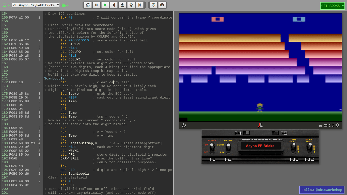
One useful resource is https://8bitworkshop.com/ where you can build your own games and run them in an emulator.
8bitworkshop
Learn how classic game hardware worked. Write code and see it run instantly.
dusty citrus
late fulcrum
One useful resource is https://8bitworkshop.com/ where you can build your own ga...
That might be more my skill level, after I learn some c. I guess the rest will have to wait.
patent hemlock
dusty citrus
There's just a big disconnect here, but I guess that's because I don't really kn...
that should not be an actual concern -- CircuitPython isn't "C" or assembly yet works amazingly well with hardware 😏
late fulcrum
Good point: anything that reduces the friction to getting started is useful
As Adam Savage points out, avoid anything that drains precious motivation
dusty citrus
late fulcrum
As Adam Savage points out, avoid anything that drains precious motivation
I just feel like I'm staring at a brick wall sometimes. I had no idea how much my motivation was attached to being in a class, taking tests, getting some sort of grade... 😦 I've found myself spinning my wheels and going nowhere for hours at a time each day after graduating college.
late fulcrum
I'm completely the opposite. I found academics stultifying and would build all sorts of stuff when I had time to myself.
patent hemlock
self-goal setting is one of the hardest things to learn if you've been totally geared on Producing The Appropriate Grade
dusty citrus
patent hemlock
self-goal setting is one of the hardest things to learn if you've been totally g...
I also should have majored in something STEM, but I nearly failed Math Education--they wanted me to take upper calculus, statistics, linear algebra, and other forms of advanced mathematics, just to teach kids how to add, subtract, multiply, divide, etc. 😲--I wasn't a strong enough math student, so I had to change tracks. I played it safe and got a degree in English. I was going to minor in some other language and apply for a cert in bilingual education, but...that was harder than it first seemed too, and I eventually abandoned it.
I don't have any of it to do over again, though, so if I want to learn something new, I need to teach myself. I often just...don't feel like I know how to do that, though. There are people who can open up a browser, watch a video, not get distracted, and pick up new skills in a couple of weeks, and I'm not one of those people. How can I become one of those people?
 slim shard
I'm not sure there are that many good youtube videos out there honestly. I just follow my interests and wander wherever my learning sense happens to tingle. But I'm probably not neurotypical.
dusty citrus
Whether NT or ND, I think I'd still need to have been introduced to the basics to understand and develop any kind of interest I could do anything with.
slim shard
I still grapple with Ohm's law derived problems...
If you ask something about the basics you might get a healthy dogpile of answers here.
dusty citrus
slim shard
I still grapple with Ohm's law derived problems...
If you ask something about th...
I think that was just my way of saying I think I've passed my learning window. Maybe I needed to be exposed to this stuff as a kid.
 rapid geode
slim shard
I still grapple with Ohm's law derived problems...
If you ask something about th...
rapid geode
slim shard
I still grapple with Ohm's law derived problems...
If you ask something about th...
i like to think of it as ohm's suggestion
slim shard
Feel free to give it a shot when you feel like it anyways. I've definitely failed to learn Japanese from watching anime. But I'm still picking up bits of code syntax and electronics knowledge.
slim shard
rapid geode
i like to think of it as ohm's suggestion
Yeah, semiconductors, just seem to sit there laughing at it...
Climbing up on the ropes and shouting "FORWARD VOLTAGE DROP!" as it leaps onto Kirchoff.
 somber spindle
dusty citrus
I also should have majored in something STEM, but I nearly failed Math Education...
somber spindle
dusty citrus
I also should have majored in something STEM, but I nearly failed Math Education...
I struggle with this too. I try to do one or more of the following:
- set a deadline
- make sure the thing I'm working on will solve a problem that I actually face
- make someone else happy
- help me learn something new, especially something that might help with my day job
Another thing I try to remind myself is that a lot of lessons can't be taught, you have to learn them the hard way. Sometimes just trying the thing can be more valuable than learning for days/weeks/months to prepare to do the thing
 honest moth
aight, I think I should give making music a rest for now. I keep going back to it, but not making much progress.
 fast ferry
making games and making a console are separate but related projects. you can make games in any programming language, or even some coding-light environments like Twine (wiki-like text adventures) and Bitsy (lo-fi graphic adventures). there are a few software "fantasy consoles" like PICO-8 (games written in lua) that have tight constraints on size and fidelity but people make every kind of game for them.
a thing that really helps is to find a community, either IRL nearby, or online organized around the tools you use to make games. game jams are short online events (like hackathons) with a theme and a deadline for completing a game, which can be really motivating. Ludum Dare has a great community for feedback after you submit a game, and Global Game Jam attracts local gatherings worldwide in January. or there are zillions of jams organized on itch. sometimes those constraints help you learn and finish very small projects.
 solar halo
tardy badger
slim shard
Yeah, semiconductors, just seem to sit there laughing at it...
Climbing up on th...
solar halo
tardy badger
slim shard
Yeah, semiconductors, just seem to sit there laughing at it...
Climbing up on th...
Semiconductors follow first and second order paths for voltage and current
Due to internal resistance, stray/leakage capacitance, and inductance that occurs at such small levels of scale.
Plus considering the energy to overcome the charge gradient of the semiconductor junction.
 patent hemlock
dusty citrus
I think that was just my way of saying I think I've passed my learning window. M...
patent hemlock
dusty citrus
I think that was just my way of saying I think I've passed my learning window. M...
nope, nope, nope, nope 🙅
get one of those "learn electronics kits" (i got one for the pi for about $35) -- go through the printed tutorials and you'll get your feet wet
dusty citrus
tardy badger
Enjoy this nice picture of mountains
so nice and flat.... except that having no near shops/infrastracture somewhat disturbs me heheh
tardy badger
dusty citrus
so nice and flat.... except that having no near shops/infrastracture somewhat di...
There is tons of shopping around me
Very suburban
valid spoke
If you slam your head enough times against something, you will learn it
late fulcrum
I have heard opinions about being "too old" to learn stuff, but I think it's rubbish. I'm old and I'm still learning new things every day. There are advantages to being a helper here, for one thing, explaining things to people helps me understand them better. For another, I get to see what all the newest things are that people are working on, so I can dive into the ones that interest me. Started learning KiCAD a few weeks ago, that's going well, about to try my first PCBA order with it.
patent hemlock
obviously too much starter fluid in the bbq
rapid geode
 ebon dew
Happy Independence Day USA! 🇺🇸
ebon dew
Happy Independence Day USA! 🇺🇸
relish it, cause its probably the last one
😛
so, should i make this next in my stream of machien demos?

 hexed talon
Hoi, do you guys know of some tiny soft easily pressed down switches? Tiny as in 6mm, or around that range? As i'm currently designing for a tiny game controller, and need the switches to not be stiff/hard/super clicky, but more membrane and soft. Same with rotary encoder. needs to be quite flat and small as well, but not hard to rotate by hand,
somber spindle
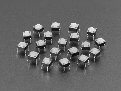
This product is really annoying to have to write a description for because it's really something you have to touch to understand! Instead of a hard plastic actuator-button, these have a ...
ebon dew
Got someone to grind some massive oak stumps that were right on the property line. Maybe by next year can put up a fence and get a doggo. 🐶

Looks like that thing. I was trying to burn them down little by little, and wasn't making much of a dent. Stump grinders are amazing.
late fulcrum
And quicker than using stump remover
hexed talon
somber spindle
https://www.adafruit.com/product/4183
Sounds quieter, but still has that "tick tick" sound even if quieter, and 250gf i guess implies 250 gram force? Which is too heavy for what i need them to do sadly. As this will be a game controller button, so buttons needs to be at least half of those switch's gram force
https://www.adafruit.com/product/3101 Checked all their switches, and seems like this is the lightest tiny one they have. 120gf

Put your project in stealth mode with these silent Soft Tactile Switch Buttons. Tactile switches are standard input "buttons" on electronic projects. These work best in a PCB ...
 opaque mauve
hello, i am trying to use both dht11 and scd40 using one arduino one r3 board. The default serial port baud rate is 9600. The sample code for dht11 uses 9600 baud and 1000 delay while the sample code for scd40 uses 115200 baud and 100 delay. Can I just use just 115200 baud and 100 delay for both? The sampling rate of dht11 is 1hz though. In terms of display and saving data the delay can be virtually done. Is this good to do?
[6:36 AM]
would it be better if i just use circuitpython for both and use different baud and delay?
[6:36 AM]
i dont know if that is even possible. I am still testing out circuitpython
hexed talon
Hoi, do you laddies know of a discord that delves into all talk about individual components/parts one uses for chips like adafruit's, pi's and whatnot?
As i am looking for certain buttons and rotaries, but don't know if this discord is best for that :P And don't know if there's a specific channel here just for component talk
patent hemlock
hexed talon
Hoi, do you laddies know of a discord that delves into all talk about individual...
just a quick hint: not everyone here is a "lad"....
hexed talon
patent hemlock
just a quick hint: not everyone here is a "lad"....
Aye, meant in a sense of "you guys" as in more a irish "you folks/people"
I'll change it to "laddies" As that's jacksepticeye's catch phrase :P
stoic mesa
hexed talon
As i am looking for certain buttons and rotaries, but don't know if this discord...
I've seen (and asked) questions of this sort here, in #help-with-hw-design
hexed talon
Thank ye! :D
dreamy furnace
Does anyone know how to use these:
https://www.adafruit.com/product/1445#tutorials

OK, this item is pretty simple - it's a panel mount pushbutton. It's not that exciting, no LEDs, no bells & whistles. But we really like it anyways – look at that lovely ...
I only bought one as a start so just mention me if you text me about it.
patent hemlock
please don't cross-/multi-post -- if your question can be answered in a more suitable channel, you'll probably get redirected
late fulcrum
dreamy furnace
Does anyone know how to use these:
https://www.adafruit.com/product/1445#tutoria...
It's easy enough to use, electrically, it's no more (nor less) than a switch.
 neon anchor
I think I took this from school lab and forgot to take it back before I graduate


but my question is, what the heck is this?
Also, this is my latest project where the opto-interruptor senses ant's movement and trigger LED sequence.
But as you can see, sometimes it works and sometimes it doesn't. I think the range of laser is really narrow, almost like a small dot, that makes it difficult to detect ants' movements.
I wonder if there is a way that I can make this opto-interrupter's laser range way wider.

like this?

this is the one that I use
late fulcrum
neon anchor
I think I took this from school lab and forgot to take it back before I graduate
Looks like a phonograph preamplifier or similar, vacuum tube of course. A picture of the bottom of the board might be helpful.
I doubt it's an issue with beam diameter as much as what you do on the receive end that counts as a detection. If something just blocks part of the beam, it may not detect it, but you could presumably adjust the circuitry or software to do so (unless the detector has its own logic internally and just provides a preprocessed digital output).
solar kindle
This was a very satisfying build. It's just a little backet with 2 magnets embedded. When it's placed in this position (left), it fools the fridge into thinking the door's closed. That way, we can put away the groceries without the door chime going off after 60 seconds. The rest of the time, it can be stuck to the side of the fridge. The fridge doesn't have a setting to turn off the door chime or even to make it a bit quieter. But it's no match for a nerd with a 3D printer and a couple magnets. 😄

 marble glade
Hi, does anyone know which help-with channel might be able to help with neopixel issues when using them with a raspberry pi? I am getting strange flickering issues when using my neopixels.
 hard estuary
marble glade
Hi, does anyone know which help-with channel might be able to help with neopixel...
hard estuary
marble glade
Hi, does anyone know which help-with channel might be able to help with neopixel...
For Pi questions #help-with-linux-sbcs is best
marble glade
hard estuary
For Pi questions <#538149593246859313> is best
Thanks!
 fair summit
The DUE is quite old and largely considered to be obsolete, though you can still apparently buy them. It uses an outdated chip.
stoic mesa
if you already have due, you can still use it.
if you are looking for a new board to buy, most popular ones nowadays are based either on RP2040 or ESP32 (such as esp32-s3) chips
 jagged citrus
See this is why i made my DX32 weather station

Thats the temperature of my classroom rn

Like shurik said get a board based either on the RP2040 (like the pi pico /w) or the ESP32
fair summit
It depends on what you want to do with it, but if you are waiting for libraries, they are probably not going to get ported.
tardy badger
I tell ya, I circle back often to the thought that the introduction of honey bees to North America was not super great. While we enjoy the spoils of their success as an invasive species, they wreck havoc on other pollinators
Especially native bees
late fulcrum
And the more prolific pollinators (flies and moths)
dusty citrus
Some kind of digikey (so with filters and stuff) but for motors and drivers?
the closest thing that I could find is pololu, but selection is limited, you get also stuff like hobbyking but then filters are huh, aliexpress is what it is ;
And finally some kind of cheat sheet for motor noise? I know that modulating to an unhadible frequency is possible to run motors quiter, or by using drivers like trinamics (which should do the same) for steppers noise can be reduced (yet in the datasheets there's no chart), or by using stuff like odrive (bldc/foc) but they're expensive
Just for browsing around and find more suitable (cheap) hardware
somber spindle
seems like you're looking for something with parametric search
I don't vouch for this site, but it seems like what you're looking for: https://www.trustedparts.com/en/part-category/electromechanical/motors-drives
stoic mesa
dusty citrus
Some kind of digikey (so with filters and stuff) but for motors and drivers?
th...
I'd also add servocity.
Or ask here and one of us may be able to advise.
 sudden violet
@stuck moth yo can I hop in?
 stuck moth
ya, we're talking about matter
 fiery stag
Hi folks. Just got my FT232H and hooked it up to a 128x64 oled display. I'm observing that a screen refresh takes nearly a full minute. This can't be right?
Which help chat should I take this to?
hard estuary
fiery stag
Which help chat should I take this to?
It depends - how are you coding it? There is #help-with-circuitpython or #help-with-arduino or #help-with-projects is a catch-all if it doesn't fit
fiery stag
Thanks! I'm using CPython on a desktop PC with the Blinka shim library. I'll take it to #help-with-projects
 weary stream
Hi folks! I am looking to buy an open source smart ring for research. Can you recommend a product that I can buy from adafruit?
fair summit
weary stream
Hi folks! I am looking to buy an open source smart ring for research. Can you re...
Is this what you mean? https://www.adafruit.com/search?q=smart+ring
weary stream
fair summit
Is this what you mean? <https://www.adafruit.com/search?q=smart+ring>
Yes exactly but I am looking for an open source smart ring like an OmniRing with code available because I want to do research on it for my PhD thesis.
fair summit
weary stream
Yes exactly but I am looking for an open source smart ring like an OmniRing with...
I don't know of such a thing, but haven't looked. You could simulate such a ring with an NFC development board.
weary stream
fair summit
I don't know of such a thing, but haven't looked. You could simulate such a ring...
I will look into it. Thank you
fair summit
weary stream
I will look into it. Thank you
https://www.adafruit.com/search?q=pn532. These are older. Several Nordic nRF dev boards (PCA10056, etc.) have NFC-A Tag capability
 chrome oasis
I just got burnt by my pi pico :(
Was testing stepper motors with arduino at high (ish) speeds, and the stepper motor was rattling and stepping irregularly
I’m guessing the voltage got sent back into the pi and damaged the power supply
Heated up to several hundred degrees
I don’t know what really caused it
thick wind
Oh no! Were you using a stepper driver?
chrome oasis
thick wind
Oh no! Were you using a stepper driver?
Yeah, the DRV8833
I’m scared to try again with another pico
I’m worried that the motor drivers were fried, and using them will destroy the next pico as well
thick wind
Was it the drivers or the pi pico heating up to oblivion?
chrome oasis
It was the pico, specifically the block of components next to the USB port which act as the power regulator
thick wind
How was the stepper driver powered?
chrome oasis
Using the pi pico VSYS. I assumed that since the steppers were being driven off 5V it would be fine
It was fine with everything else
But either it was a ticking time bomb (would have broken at that time anyway) or the irregular stepping was the problem.
thick wind
My guess would be you drew too much current through the Schottky diode between VBUS and VSYS. It’s rated for 1A, but i know the DRV8833 can draw at least 2A if the limits aren’t set.
If you can help it, I’d always recommend using a separate power supply for motor drivers. Those draw pretty large currents, and they’re not currents you want to draw through a development board if you can help it.
chrome oasis
Yeah, especially considering I was only using one - and was about to add 3 more.
chrome oasis
thick wind
If you can help it, I’d always recommend using a separate power supply for motor...
One thing though, if I got a 5V power supply and wired it to the motors and the drivers (shared ground) would that work or would the current be going through the pico?
thick wind
That would work.
chrome oasis
Ok thank you
 solemn apex
does anyone know circuit pythn here
im using a maker pi rp2040
im using an ir receiver and tt motor wheel
it was working good on my pc and when i disconected it and conected a powerbank to it didnt work
i ssaved the coding in the maker pi but still cant do it
fair summit
^^ above addressed in #help-with-circuitpython
 onyx jetty
just a quick general question, is circuit python or arduino more supported for Matrix Portals?
hard estuary
onyx jetty
just a quick general question, is circuit python or arduino more supported for M...
What do you mean by supported? For example, there are more CircuitPython projects than Arduino for MatrixPortals on https://learn.adafruit.com, but they'll run either just fine.
onyx jetty
hard estuary
What do you mean by supported? For example, there are more CircuitPython projec...
I can see that they are both supported. I just switched to Arduino since it seems to work better. The docs are more clear about Arduino in my opinion.
 leaden moth
Hello. This sort of forum/discord is very new to me. I'm a truck driver, and am wanting to make something that will allow me to mimic an SD Card off my Dash Cam. I'm willing to learn and do the work, but I'm confused where to start. Adafruit may or may not be the right decision for me. What do you think? Am I in the right place, or does anyone know of someplace better?
dusty citrus
leaden moth
Hello. This sort of forum/discord is very new to me. I'm a truck driver, and am ...
sounds like a xy problem, what's the end target? why do you want to mimic a sd card? to export the video wirelessly or what?
leaden moth
xy problem. not sure what that is.
dusty citrus
leaden moth
All the drivers I know have dash cams. Some of us would like to be able to copy what are called loop files off the SD Card as the files are written.
dusty citrus
leaden moth
All the drivers I know have dash cams. Some of us would like to be able to copy ...
something like a toshiba flash air ?
leaden moth
The flashair will only allow you to copy files through their app, and does not work when the sd card is being written to.
That xyproblem was very helpful. So here's what I'm trying to do:
I want to livestream my truck. You can do this with a phone, but the quality of both the video and the connection stability is not very good in some places. Most dash cams have a microSD card port to store footage. They also have what's called a "loop mode", where video is saved in 1, 3, 5, or 10 minute chunks as files.
What I want to do is when a file is closed (video loop file is done and a new one is created) I want to copy the lastest closed file and upload it to my computer at home. My home internet connect is rock stable, and I have greater flexibility to broadcast from it than I do from the cab of my truck. It also gives me the added benefit of having a broadcast delay, so if I'm in the mountains and internet coverage is spotty the dash cam continues to record and my device/solution I want to make will keep trying to upload the older files until it comes back online again.
I thought this would have been a solved problem, but I'm guessing the way SD Cards are written to make it hard to read and write at the same time.
I have seen tools like SDWire and clones, but they do not allow you to read files when it is being written to.
ebon dew
IndustryCity.com (where Adafruit is moving) looks cool as heck. Bonus points for the initials IC, that's just perfect. 
patent hemlock
even better - i got an order in and shipped before they have to pack up! 😈
 edgy juniper
leaden moth
The flashair will only allow you to copy files through their app, and does not w...
edgy juniper
leaden moth
The flashair will only allow you to copy files through their app, and does not w...
Do you have to use a dash cam?
leaden moth
I'd prefer to. Other cameras do not dampen the vibrations in an 18-wheeler, as well as inconsistent lighting.
ebon dew
How big are the files? Could setup an FTP server, check for new files, upload them to a home server that shuffles them to a NAS. There are a lot of ways to skin that cat.
 midnight willow
Hey there, I need help with iot esp32 related issue, where could I post request for the same
brave copper
how wide is the 10 bar graph? this is what I need
| | - this area here of the bargraph
late fulcrum
brave copper
how wide is the 10 bar graph? this is what I need
---------------------
| ...
I think the LEDs are on 0.1" centers
fast ferry
leaden moth
The flashair will only allow you to copy files through their app, and does not w...
disappointing that the flashair won't work while writing. I think the Eye-Fi Mobi was the leader in wifi SD cards. the company died in 2016, but the app may still work from a third-party? it had native support for auto-transferring photos and videos and sending them to cloud services, including FTP AFAIK.
the Mobi cards seem to sell for $$$$ used; maybe they're still best in class, heh. the older models are cheaper, not sure what the diffs are. I have an older one and never took the time to set it up.
fast ferry
it's too bad the existing dashcam doesn't have auto-upload built in. I think some do?
dusty citrus
I'm getting like free insults/threats for scraping on smaller shops. Pretty interesting how rather than fixing their stuff, even by providing free fixes/suggestions, they rather keep being agressive and try to scam you, and then they wonder why people would rather buy on amazon/aliexpress
late fulcrum
It would take me a lot more to make me buy on amazon. What does their robots.txt say?
 wanton stump
Guys I'm new here... so I wanted to buy the ssd1327 oled and wanted to see which interface is faster I have seen that spi is faster than i2c, but is there anyway to increase the speed to look like it's same fast as spi interface? And would it conflict with another modules which uses the same i2c bus if I follow this schematic as per the adafruit one?

My waveshare ssd1327 conflicts with other modules and creates like a TV static on the display. So I want to make sure if this one makes the same problem. I have the same one on the picture and is it necessary to include those diodes for spi?
 late fulcrum
wanton stump
Guys I'm new here... so I wanted to buy the ssd1327 oled and wanted to see which...
late fulcrum
wanton stump
Guys I'm new here... so I wanted to buy the ssd1327 oled and wanted to see which...
You can increase the speed some, maybe 400kHz or even 1MHz with some setups, but SPI will cheerfully operate at 10MHz, which I2C cannot do, due to its passive pull-up design.
patent hemlock
wanton stump
My waveshare ssd1327 conflicts with other modules and creates like a TV static o...
what do you mean "conflicts with other modules"? does the display work fine without whatever "other modules" are?
wanton stump
patent hemlock
what do you mean "conflicts with other modules"? does the display work fine with...
no, when I connect the display with mpu6050, hmc5883l and other modules, the display produced grabbed images
Now I don't have the display right now to test as I removed the waveshare board to make custom one
valid spoke
wish desoldering equipment was cheaper
hakko has the FR301 which is 300 bucks but its very bulky
and they have the FM204 which would be ideal
but its over2x the cost!
late fulcrum
For desoldering, my usual approach is an ordinary inexpensive solder sucker. Sometimes I reach for solder braid, which can work well if you have a powerful enough iron and add some flux. There's also integrated irons with vacuum bulbs that aren't too expensive (<US$50), I use one of those occasionally as well.
valid spoke
late fulcrum
For desoldering, my usual approach is an ordinary inexpensive solder sucker. So...
i normally use a FR301 that i have access to at work
but
i desolder a LOT OF CAPS
and want something at my home lab
late fulcrum
I've been tempted multiple times to buy one as I repair circuit boards on a regular basis
valid spoke
yeah i repair a lot of audio equipment
cuts down the time by a lot
if i had one of those irons that also fed solder at the same time
late fulcrum
I also replace a lot of caps...
 valid spoke
id get it done so fast
dusty citrus
there are some heated up suckers that either use a spring loaded thing as the standard ones, or a pump, but I have no experience with those
dusty citrus
like
 valid spoke
late fulcrum
I also replace a lot of caps...
valid spoke
late fulcrum
I also replace a lot of caps...
where the green boys from
valid spoke
dusty citrus
like
never tried those
valid spoke
late fulcrum
I also replace a lot of caps...
how long does something like this take you by hand
because i dont have as much practice but when i use fluxed braid it still takes me a bit longer
dusty citrus
on ali they're usually at 30 bucks, I dunno how they're like, conceptually its just like the spring one by automated, so it's still a one shot, not a costant sucking
valid spoke
yeah im looking for something more rugged
late fulcrum
I'm no speed demon, probably 1-2 caps per minute?
valid spoke
since this is a sidebusiness i got right now to help pay for my degree and tools
late fulcrum
If it's a side business, you can factor in your hourly rate to figure out if it's worthwhile (I'm guessing it is, you can also deduct it as a business expense if you're in the US, tax laws vary)
valid spoke
late fulcrum
I'm no speed demon, probably 1-2 caps per minute?
even with only the FR301, you can do 10x that
especially with some nice tweezers
late fulcrum
Exactly
I do have some nice Vomm tweezers as well as hemostats, etc., which come in handy
valid spoke
i have these medical tweezers i got at a surplus store

they lock in very nicely around leads
for a cap
late fulcrum
I probably spend as much time buying capacitors as installing them, but if I were doing it as a side business, I'd order in bulk for many of the common values and save a lot of that time. I generally replace electrolytics with 105° or 125° long life, polymer, or sometimes film caps for smaller values.
dusty citrus
or knock offs https://shorturl.at/lJnrT
valid spoke
valid spoke
late fulcrum
I probably spend as much time buying capacitors as installing them, but if I wer...
i bulk buy most of the values now
anything 1uf or smaller gets a kemet RSB film
and the rest is long life high temp caps
recently i figured out this hold on
late fulcrum
My last two were disappointing, I repaired an amplifier only to find out the speaker was damaged, and a digital piano only to find out the CPU board was flaky
valid spoke

for motor control circuits
ive been using 2 parallel caps one polypropylene and one polyester
and it cranks down on temeperature speed deviations a lot
late fulcrum
That's a handy chart. I see they don't show polystyrene, but that makes sense as polystyrene caps don't tolerate high temperatures well
I don't see a lot of polycarbonate caps these days, they seemed to be more popular a while ago
valid spoke
i dont know much about other cap types exccept electrolytic polymer the hybrid ones polyester and PP caps
valid spoke
late fulcrum
My last two were disappointing, I repaired an amplifier only to find out the spe...
just finished fixing a deck that has 4 different MCUs
changed 120 caps
late fulcrum
Yeah, I don't buy a lot of exotic caps.
valid spoke
redid the power supply
to find out one of the MCUs is fried
and if i want it to work i have to drop in a teensy or a nano to replace it
and code it up
somehow
late fulcrum
I find a lot of gear buys in the power supply, and it's often built to a lower spec than the rest of the electronics
valid spoke
late fulcrum
I find a lot of gear buys in the power supply, and it's often built to a lower s...
what do you mean
late fulcrum
Often there will be two (or more) boards inside, one board a nice G4 one with the implementation circuitry on it, and the other a cheap one-sided phenolic board with the power supply.
late fulcrum
A recent example
 valid spoke
so crappy that traces will lift with minimal heat
damm yamaha what you doin


this is the most recent machine i worked on
the one with the dead MCU
late fulcrum
I work on some fancy equipment, but set aside extra time to explain things to customers, who often have some quaint ideas about how things work. If they want me to install all PTFE and C0G caps and use silver solder, I'll do it. If they love PIO, I'll install those. But first I'll explain what does and doesn't matter, and offer to let them listen to the difference.
valid spoke
cause a previous tech confused a 10v zener and a 6.1v one
valid spoke
late fulcrum
I work on some fancy equipment, but set aside extra time to explain things to cu...
im the same way
if they want to pay for it go ahead but ill let them know
the only effect youll get is placebo
late fulcrum
I don't often have to work on things someone else has worked on - except when repairing test gear. People who own test gear value it and tend to be the sorts that fix things, so a lot of test gear has been worked on before.
What I don't tell them is I use silver solder most of the time anyway (unless they insist on lead free).
valid spoke
sadly i see a lot of previous techs work and most of the time they are hacky
or think they know better than the people who made the machine
late fulcrum
Or technically, silver bearing electronic solder, not the sort of high temperature silver solder used on jewelry
valid spoke
i have never used silver solder
is it just stronger or does it have some other benefit
late fulcrum
I got used to it working on old Tektronix vacuum tube oscilloscopes, where it was required due to the way the ceramic terminal strips were constructed. I found it's really nice solder to use.
It melts nicely, fluxes well, and gives absolutely gorgeous joints.
valid spoke
i always use just
kester sn60pb40
would it be worth for it to give it a try?
and does it come fluxd
late fulcrum
I use Kester sn62pb36ag2 with 44 RMA flux
Yeah, ordinary Kester flux core solder.
It is Not Cheap, but a one pound roll lasts me quite a while
valid spoke
im looking for a new flux because the one i have used until now is liquidy
and it moves around too much
makes cleaning a mess
MG chemicals one forgot the number
late fulcrum
The flux question is complicated. Clean or no-clean is just the beginning of it.
late fulcrum
I work on a lot of older equipment so I see a lot of rosin flux, so I normally also use rosin flux. But not always.
And the difference between RA and RMA is important. I bought a spool of RA once and didn't realize it had to be cleaned, and the joints all grew white fuzz. Oops.
valid spoke
yeah its very picky with clean
i gotta try different things for solder and flux
been using the same combo for a decade now
late fulcrum
A lot of stuff I work on is point to point vacuum tube gear, which favors different material than PCBs
 late fulcrum
A know a handful of audiophiles and (especially) guitarists who strongly prefer vacuum tube gear.
valid spoke
i dont understand it
the only reason id get some is to run those cool magic eye tubes
i know they have a more pleasing distortion
late fulcrum
Vacuum tubes work similarly to FETs, but there's only one flavor (comparable to N-channel)
And, of course, with higher voltages
valid spoke
yeah the
you get zapped and its not longer your problem voltages
i just dont understand why they like them
well didnt
now i do
because i thought they were all about signal fidelity
audiophiles that is
but they like the "warmth" that comes with the distortion they have
late fulcrum
They think they are, but what they're really after is a sound they like. And there are some psychoacoustic reasons that tube sound appeals to some people.
late fulcrum
It's more subtle than that. Many tube circuits have moderate gain and little negative feedback. Early (and current cheaper) semiconductor circuits use huge gain and massive negative feedback which has phase and overload distortion that many people dislike.
valid spoke
is it because the distortion on a semiconductor is a straight clipping of the signal
late fulcrum
There's also a headroom issue, with hundreds of volts to play with, a brief transient doesn't get clipped as much as with lower voltage circuitry, and that's audible.
valid spoke
and tubes have a more smooth clipping
valid spoke
late fulcrum
There's also a headroom issue, with hundreds of volts to play with, a brief tran...
ahh
neat
late fulcrum
And that smooth clipping is similar to the way human ears clip: that (this is my guess here) is why tubes sound "louder" for the same wattage
valid spoke
i have been doing a lot more coursework and research on BJT FETs MOSFETs amplifier types etc
more semiconductor stuff in general
only thing i really learned is i really dont know jack
but i think ill be going into the semiconductor field after i graduate
valid spoke
late fulcrum
And that smooth clipping is similar to the way human ears clip: that (this is m...
see that makes sense
late fulcrum
I am quite familiar with that feeling. I'm currently studying magnetics (transformers, inductors, etc.) and have the same reaction
valid spoke
im taking a class on power systems which is just
magnetism meets ohm law
it makes more sense than semiconductors
semiconductors are chemistry and witchcraft
to me at least
i understand how they work and how to use them but the why they work
is wild
late fulcrum
That's part of the appeal of vacuum tubes, especially when I was earlier in my learning journey. You could see the individual parts and understand how the electrons flowed and were attracted or repelled by elements with various voltages on them. They even made special tubes with phosphor on the plates so you could actually see the pattern of electrons impinging on them
valid spoke
the green funny ones?
valid spoke
late fulcrum
That's part of the appeal of vacuum tubes, especially when I was earlier in my l...
well i do like them for that reason they make understanding semi stuff easier
but for example recently i learned that
late fulcrum
The magic eye tubes are a variant, but there were classroom demonstrator tubes which were just giant triodes the size of soda cans with big structures which were great for explaining what was going on
valid spoke
to make wafers they put this blood looking substances on a centrifuge
and they spin it
and it looks very metal
cause everything gets covered in semiconductor blood
and then they expose it to oxygen to oxidise it and its a wafer

 late fulcrum
It does looks like a scene out of a strange fantasy or sci-fi film with a dark ritual going on
valid spoke
late fulcrum
The magic eye tubes are a variant, but there were classroom demonstrator tubes w...
do you have any part numbers or anything i can look at
would be cool
valid spoke
late fulcrum
It does looks like a scene out of a strange fantasy or sci-fi film with a dark r...
exactly
i was gonna go into the power generation field
but it lacks the cool factor
now semiconductors has some weird arcane science thing going on
its innovative and in demand
late fulcrum
They haven't made them in decades, so they're expensive collector's items these days, but here's a nice writeup on one: http://lampes-et-tubes.info/dt/dt010.php?l=e
valid spoke
yeah i just want to get any videos or anyhting i can use to help the people i tutor understand them better
BJTs are scary and then they understand them
and then we go to JFETs
late fulcrum
I did ask the folks who make the Korg "Nu-Tube", which is a vacuum fluorescent display used as a triode, if they'd make a demonstrator variant, which wouldn't be a big change, but they didn't consider it worth the trouble.
valid spoke
and then it gets weirder
valid spoke
late fulcrum
I did ask the folks who make the Korg "Nu-Tube", which is a vacuum fluorescent d...
that sucks
i do like demonstrator circuits for showing how components work
late fulcrum
BJTs mystified me for a while. Electrons I can understand, but holes?
valid spoke
well for the function of it i like people to think of it as a faucet
late fulcrum
I buy a lot of classroom stuff on eBay from people who don't know what it is, like this beam tube with a magnetic field so you can bend the electron beam
 valid spoke
and then we o into the different regions
and Q point
and common emitter and collector
and it gets freaky
but they get it
and then we get to JFETs and the negative voltage at the base
and the new names
and people get spooked
late fulcrum
I kind of liked the "transistor man" model they use in Art of Electronics, but I still don't really understand how a small current into the base enables a larger current into the collector.
valid spoke
oh they got a version that works with shop air, and i got a 21 gallon air tank so i dont needto hear my compressor run all the time
 valid spoke
late fulcrum
I kind of liked the "transistor man" model they use in Art of Electronics, but I...
valid spoke
late fulcrum
I kind of liked the "transistor man" model they use in Art of Electronics, but I...
i love that book
im trying to buy that X version they got for more info on components
late fulcrum
I'm amused that the names still hearken back to the vacuum tube days. The "emitter" is like the cathode in a tube, which emits electron. The source is, again, like the source of electrons.
I finally bought the entire trilogy, the original, the X chapters, and the Learning the Art of Electronics lab book. I found them all useful.
valid spoke
i have to get the last two
but books are expensive
and i already spend a bunch of money on them
late fulcrum
Yeah, the set was over US$100 if I recall
valid spoke
damm
i think i paid 70 for the original alone

next time i get a buncha LEDs ill get it
i will go finish doing all the different annoying things i gotta go do now
take care @late fulcrum thanks for the chat
patent hemlock
valid spoke
cause everything gets covered in semiconductor blood
not quite (i built 4116's back in the day() -- the "blood" is a photo-resistant coating that masks each layer of the wafer/semiconductor
late fulcrum
I've used a fair number of 4116s
valid spoke
patent hemlock
not quite (i built 4116's back in the day() -- the "blood" is a photo-resistant ...
It's still very cool nontheless
And dark arts sci Fi stuff
patent hemlock
what amazes me is that the "basics" haven't changed in over 50 years!
tardy badger
This is the biggest black widow I’ve ever seen

It’s well over a centimeter in diameter in the abdomen
 quick helm
Napalm. It's the only safe bet.
tardy badger
Eh, it’s in a basement window well outside. It’s not hurting anyone right now
It’s eating bugs that would usually come inside
quick helm
tardy badger
Eh, it’s in a basement window well outside. It’s not hurting anyone right now
That sounds like something a Black Widow would say.
tardy badger
🤷♂️
quick helm
I'm having a tricky time finding the correct results for something I want to try: how to make an audio visualizer that reads audio files on my Raspberry Pi 4 B and displays it on an LED matrix I have.
I say having a tricky time because I'm getting different results on what people want to call it: audio visualizer, audio spectrum, audio waveform, and so on.
late fulcrum
It does depend on what you mean by "visualizer". Some people think of the abstract patterns the Atari Jaguar CD makes. Some people thing of bar graphs of frequency spectra. Some people think of geometric renderings like the Playstation Trance game.
Or maybe you're looking for Lissajous figures
quick helm
Ah, right right, I gotcha, I left that part out. Something like this:
https://www.instructables.com/Raspberry-Pi-Audio-Spectrum-Display/

Instructables
Raspberry Pi Audio Spectrum Display: Use the DFRobot 64x64 RGB matrix panel with a Raspberry Pi 3 B+ to bring a dance party with you wherever you go!
DFRobot reached out to me to do a sponsored project for their 64x64 RGB LED matrix. At first I had tried to use it with the ESP32 Fireb…
However, I'm using a DotStar matrix, 8x32.
late fulcrum
Seems like you're most of the way there, you have the visualizer, just need to modify the output to drive a different display
quick helm
And, I think this example video is actually using a mic to pick up on the sounds and display it (with a delay). I'm sure there's something out there that can read MP3 files and display a visual spectrum with the correct timing.
late fulcrum
Oh yeah, there's the input side too.
quick helm
Well, now that I think about it, having a mic pick up on it might be better. Unless there's a way to get Python to read my Spotify playlist and know how to visualize the beat, then I think that'd be the most viable option.
This is the closest project I found on the Adafruit site, although it does use individual strips instead of a matrix.
https://learn.adafruit.com/raspberry-pi-spectrum-analyzer-display-on-rgb-led-strip/page-1

Turn your Pi into a music display that bounces along to mp3 playlists
late fulcrum
There will be some integration work to get all the pieces to coöperate
quick helm
I honestly thought I saw a project out there that did use a matrix and Python to accomplish what I'm looking for. But, it's very possible that I'm misremembering.
EDIT: Oh geez, I'm blind. They're not using multiple strips, they're using a single strip. Well, I suppose it wouldn't be too hard to reformat the code to reflect my matrix, which is designed like a single strip in an S-pattern.
 sharp jasper
does anyone make satellite transceiver ics, sorta like iridium? i like iridiums offerings but theyre impossible to get my hands on
globalstar appears to make something in line with what i want
tardy badger
reworking my RP Watchy Design. it's all coming together 🙂

spot the different between the last one and this one. it's subtle. and then tell me what I realized that caused the change xD
 tardy badger
I’ll probably add a few more things to this since I have so much space left
ebon dew
tardy badger
spot the different between the last one and this one. it's subtle. and then tell...
You got the traces to the ribbon cable backwards on the first one. 😉
tardy badger
Yup lol
The wiring was fine for the previous version but I’m changing the way the display connects 🫡😬
ebon dew
Happens. I was working on the RA8875 driver chip and did something similar. Caught it early though.
tardy badger
Thankfully I’m a lot better at double checking stuff before ordering now 🤣
ebon dew
That one uses a 40 pin cable and very similar layout.
Yup, can't count how many times I've sent it to fab just to double check again after and spotted an issue. Now I resist the urge to check again after ordering. Any issues I'll find when it gets here.
That was fun, thanks for that where's waldo puzzle. 🙂
I never did finish the RA8875 featherwing. It was too complicated with hundreds of pins, the chip itself has over 100 pins. Gave up.
tardy badger
You should definitely revisit it one of these days
ebon dew
Only the S3 is powerful enough to drive it but there's no displayio support so even if I did finish it I'd have to write a ton of code for the graphics library to make it more capable. Might take Scotts idea and just try to drive it without the RA8875 as a dot clock. At like 840x460 it'll be slooow though. Couldn't justify the amount of work involved with either hardware avenue.
tardy badger
Eh, something’s are worth doing just because even if it doesn’t make 100% sense
ebon dew
I might scrap the entire idea and just make a feather adapter board that the Adafruit RA8875 board gets soldered to. That's the far easier method.
tardy badger
Perhaps
I’m going to make myself a IMX RT1176 feather
It’s going to be so overpowered for a feather but I just think about how cool it would be
ebon dew
ohhh is that the big one in the RT series?
tardy badger
It’s one of the big one, not quite as new as the 1180 but really nice features
ebon dew
only thing I don't like about the RT (from an online API perspective) is the lack of ram.
most of my projects are display and api oriented so my projects eat ram for breakfast.
tardy badger
1176 is similar to the RP2040 in that it requires external flash
But it has 2MB of ram
ebon dew
that's storage though not the sram or psram. i think the rt has like max 512kb of ram?
tardy badger
And support for off chip PSRAM and SDRAM
ebon dew
yes that's the ticket, now i'm interested.
ebon dew
i would be interested in that. i'd buy one. sign me up.
tardy badger
Fun part is it’s a 289 BGA chip
But pretty decent pitch so it’s fairly easy to route
rapid geode
tardy badger
Fun part is it’s a 289 BGA chip
i think i have an application for youyr fpga feather
still quite far from being ready to try it though
tardy badger
Oh yeah?
rapid geode
to read an accelerometer then do some math to dynamically change the speed of a motor to reduce resonance

 tardy badger
Oh that would be cool
rapid geode
(cnc spindle)
the rp2040 portion would talk to the pc giving the end command after calculation
should be fun
ha
tardy badger
Is 48MHz fast enough to do all that? It does have DSP blocks for 18x18 matrix multiplication
ebon dew
some 3d printers use resonance sensors for input shaping so they can print faster with more accuracy. sounds like a good application.
rapid geode
same basic concept, except we are detecting resonance in the spinning tool. "chatter"
if you modulate the speed and the feed, that resonance cant build up
ebon dew
so it doesn't chunk through to fast and explode?
rapid geode
not too fast. sometiems its too slow.
sometimes you just hit a perfect frequency that can build in the work or machine.
ebon dew
oh yeah that sounds complicated. why don't cnc come with stuff like that built in? or is this a completely custom spindle? images kind of look custom.
rapid geode
this will detect any build up (amplitude) and then vary speed and feed a few percent.
it can also detect a hard crash too and shut the machine down. in conjunction with force feedback on the servos (yay ethercat)
anyhow. its for phase 2. first i need to get the first few machines sold.
they will have the sensors, and then the hardware/software can be added later
machined some hard steel yesterday. to hold my vise. that was fun
 fast ferry
ebon dew
some 3d printers use resonance sensors for input shaping so they can print faste...
fast ferry
ebon dew
some 3d printers use resonance sensors for input shaping so they can print faste...
input shaping isn't a live feedback system, though, it's measured up front with an accelerometer mounted to the effector while running thru fine, fast movements in a frequency sweep. or at least the systems I've seen. I've done it on my printer with an adafruit ADXL345 breakout.
live would be cool. fairly sure I have different resonances at different Z heights.
rapid geode
ahh. so its like an auto tuning to get good acceleration and jerk params
as opposed to a real time reaction to whats actually happening during operation
fast ferry
yeah, coefficients for a function that smooths hard motions to avoid triggering resonance.
fast ferry
there are a few different functions, and you sort of divine which one to use by looking at your accelerometer graph after the test.
rapid geode
someone is working on jerk control for linuxcnc
fast ferry
sure, belts, or my fishing lines lol
fast ferry
very cool tho
rapid geode

Low jerk motion is highly critical for many applications including robotic systems, here at SOLO we have developed an Embedded on board Motion Profile Engine that offers the highest level of Smoothness with extremely low traffic on your data line, only 1 point per trajectory!
Visit our website: https://solomotorcontrollers.com/
To purchase a co...
hehehe
fast ferry
I always figured CNC feed rates were limited anyhow. they hit corner accelerations that high?
maybe for laser cutter control
rapid geode

*** Would you like one of these machines? ***
We are now creating 2 lists. One for people interested in the production machine. No money is required, just send your contact info and we will get back to you in order when machines become available to purchase. You then can decide if you want to put a deposit, or pass to the next person on
The ...
they have to make really sharp transitions at speed
this is linuxcnc with no jerk control. the machine vibrates a LOT
and leaves some marks on the part as a result
ha. you can hear some of the chatter resonance is the second helix motion. thats when youd want to modulate the spindle speed up and down 100rpm
fast ferry
very nice. showing my inexperience, heh. 😶
rapid geode
hehe
it becomes very apparent when you have a fast machine. mines limited to 0.3G there. and only about 1/3 full speed. when i get the ethercat motros it will do 1G
fast ferry
better bolt that one down with extra bolts
fast ferry
amazing
I printed this box on the diagonal as oriented in the photo, and input shaping completely countered ringing at low Z, but you can see it crept in around the hole in the middle and at the corners at the top. it's a wobbly delta with thin towers, and I need to stiffen it with crossbracing. one day.

or upgrade to an flsun T1 and bury this one out back 😂
rapid geode
flsun. ugh. ha. apparently they have been bot spamming reviews
fast ferry
that's unfortunate. their hardware looks great.
ebon dew
no system is perfect.
 hard halo
what are the best electrical/electronics engineering magazines you know?
rapid geode
ebon dew
no system is perfect.
how you respond to criticism is what makes or breaks a new tech product.
ebon dew
hard halo
what are the best electrical/electronics engineering magazines you know?
The Adafruit Python on Hardware Newsletter.
 patent hemlock
ok, i just had a really dumb thought but it's so stupid i had to share: while getting up from the floor (petting cat), i noted i was in the Hero 3-Point Landing position and it occurred to me that if i had the power of flight, i'm pretty sure i'd have enough control to land gently and not leave divots in the ground, not to mention not crushing my kneecaps every time...
late fulcrum
I too have thoughts like that. The other day, I was reaching for the light switch in the dark and it wasn't where I thought it was. I could have just figured I wasn't standing quite where I thought I was, but my first thought was actually "maybe I've become magic and can reach through walls".
tardy badger
patent hemlock
ok, i just had a really dumb thought but it's so stupid i had to share: while ge...
Honestly, I’ve thought the same but have also thought “it’s probably for dramatic effect.”
Super powers, you probably have super knees
 elfin viper
Hi y'all, I have an esp32 and CircuitPython on it. My project does well, but I want to shorten debug time with installing a debugger in my code. I've chosen debugpy, but I don't know how to install it on my controller. A sole import of debugpy breaks the code and I don't know how to use it appropriately. Do I need to create my custom CircuitPython with this library available? How can I handle this issue in a convenient way? Or do I have better chances with another approach? Any suggestions are welcome.
 full spade
<@&617066238840930324> i need some help related to arduino. can anyone join vc?
fair summit
full spade
<@&617066238840930324> i need some help related to arduino. can anyone join vc?
Please don't ping. And just type your question in #help-with-arduino
full spade
I need some information about how to use arduino with python
fair summit
full spade
I need some information about how to use arduino with python
please ask a more specific question in #help-with-arduino
full spade
ok
 charred lintel
elfin viper
Hi y'all, I have an esp32 and CircuitPython on it. My project does well, but I w...
charred lintel
elfin viper
Hi y'all, I have an esp32 and CircuitPython on it. My project does well, but I w...
Debugging on microcontrollers is non trivial, and you can't use debuggers written for CPyhton.
This is a guide from espressif that should help get you started https://github.com/espressif/vscode-esp-idf-extension/blob/master/docs/tutorial/debugging.md
Also found this library for circuitpython, no idea if it works https://github.com/urfdvw/CircuitPython-Debugger
dreamy furnace
I have a question: How did everyone learn Circuit Python? Just tag me with an answer.
fair summit
dreamy furnace
I have a question: How did everyone learn Circuit Python? Just tag me with an an...
do you need to learn Python too, or are you asking about the CircuitPython-specific part?
dreamy furnace
fair summit
do you need to learn Python too, or are you asking about the CircuitPython-speci...
I know python and I'm learning Circuit Python on youtube but I would like to know how to become a lot more advanced.
fair summit
dreamy furnace
I know python and I'm learning Circuit Python on youtube but I would like to kno...
Have you looked at our https://learn.adafruit.com?
are you look at Prof Gallaugher's videos online?
dreamy furnace
fair summit
are you look at Prof Gallaugher's videos online?
Yes
Funny how you knew
dreamy furnace
fair summit
and you've also been reading our Learn Guides?
I haven't but know I'll give them a go 👍
fair summit
Also you can read the documentation: https://docs.circuitpython.org/en/latest/README.html. Most people learn well from examples, and that's what the Learn Guides do for you.
https://learn.adafruit.com/welcome-to-circuitpython
https://learn.adafruit.com/circuitpython-essentials
dreamy furnace
Thank you!
 fading turtle
Hi all, I'm trying to find out the yearly event Limor holds for Women in STEM. I have a person I would like to nominate, but I can't find a link or recall exactly how it was worded in headlines.
I think I missed it. International Women in Engineering Day. I'm sorry, I've been very distracted the past few months.
hard halo
I have 125 pcb assembled and I need a company to make the case of it, what is the name of the company I should look for?
I want to send them a 3d model and I need them to make the plastic
and maybe some iron too
but I do not need people to assemble it, so it's not 3PL (for what I understood about 3PL)
elfin viper
charred lintel
Debugging on microcontrollers is non trivial, and you can't use debuggers writte...
Many thanks @charred lintel , I'll take a look on this this week
late fulcrum
hard halo
I want to send them a 3d model and I need them to make the plastic
I've worked with Studio KMD before on such things: https://www.studiokmd.com/

Studio KMD
tardy badger
Corn is looking delicious this year (home grown)
 valid spoke
Very nice corn
A friend of mine used to bring me corn from his place
From Iowa
Love making soup with corn
I'm choosing a new MCU for this project I'll be working on for a long time and everytime I have to start a new project and choose a new one I remember that I know very little at the end of the day
Might try a teensy or one of the cortex based metros
late fulcrum
Those both seem like solid choices to me
rapid geode
tardy badger
Corn is looking delicious this year (home grown)
corny. i got one single lonely corn ear. my pumpkins are doing well though. 7"+ now for 2 of them
 valid spoke
late fulcrum
Those both seem like solid choices to me
valid spoke
late fulcrum
Those both seem like solid choices to me
I'm doing DSP with it
So I'm looking at data sheets for the ADC and doing math
And I'm trying to figure out how much memory I'll be needing
But I've never done anything with a UI that wasn't like a gauge before
I might just have to order 2 different ones and try em out
Cause I noticed the teensy stuff and Metro cortex based ones have really good clock rates
More than I need
And are geared towards DSP
But the esp32 s3 has so much memory for me to waste
I wish I had less options
hard halo
late fulcrum
I've worked with Studio KMD before on such things: https://www.studiokmd.com/
Injection moulding right?
late fulcrum
Right. They'll usually prototype with 3D printing, but can move forward to injection molding.
We had one customer that changed the thickness requirement from 1/2" to 3/8" at the last minute, so they ended up asking me for a 3D model of the populated circuit board, and made cutouts for all the taller components.

 edgy orbit
Does adafruit generally have a booth or anything set up @ defcon?
fair summit
edgy orbit
Does adafruit generally have a booth or anything set up @ defcon?
Nope, we don't have that kind of presence at conferences.
 foggy wraith
this is a student project me and my friend have been working on this summer. we hope to share more about it in the show and tell tomorrow: http://kck.st/3LwDNGR
Its a drop in dev board for wii style remotes thats arduino compatible (esp32) and equipped with a bunch of cools features (IMU, IR LEDs, battery charging, speaker, haptic feedback, USB type-c, and a bunch of buttons) bringing some fun retro nostalgia to your projects.

Kickstarter
Transform Your Nostalgic Controller into a Versatile Tool for Home Automation, Gaming, and DIY Projects.
 vague nexus
Hi guys! I was wondering if I can capture my toy rc drone transmitter's rf signals with a nrf24l01 module using uno r3. Is that possible?
maybe nrf module isn't for this purpose just wanna explore!
actually trying to make something like to capture the signals and replay that to control the drone from my uno or esp32 s3
late fulcrum
vague nexus
Hi guys! I was wondering if I can capture my toy rc drone transmitter's rf signa...
Probably not. There are four different general standards in common use.
 round minnow
I think more than 4, and nrf24L01 does not work with any of them. What frequency band does the rc drone work on, then what protocol?
 cold pebble
I just got a raspberri pi pico w set up on a breadboard and I am so happy
I've had it for like a year but life happened and I never even found time to solder the headers. I just did that this week and it seems to be working! (I had to borrow someone's soldering iron lol)
 azure stone
Hi people, I would like to know if there is support for the board lilygo T-Display s3 pro (with screen)
stoic mesa
what do you mean by support?
as in, can you program it in Arduino? yes
Can you get help with using it in this discord? possibly, if one of us knows the answer. But no guarantees - almost all of us are volunteers, not paid tech support
azure stone
The question is has anyone tried to run it on the board
fair summit
azure stone
The question is has anyone tried to run it on the board
I don't know what you mean by "it"
azure stone
I mean has anyone used this board before with CircuitPython?
 celest latch
Hello everyone
Can anyone help with a CNC plotter 2D machine pleasee ?
late fulcrum
You're better off asking your question
celest latch
late fulcrum
You're better off asking your question
I have a problem on the pen (who is connected to SERVO MOTOR) who is drawing my .gcode so idk whats the solution ?
late fulcrum
Is it a mechanical problem, or a control issue, or what?
 fossil dawn
Adafruit product suggestion:
Sell a 23.4MOhm 0.25% 5ppm resistor 😆
 late fulcrum
I remember one of DigiKey's vendors had auto-generated renderings of resistors, but it confused milli-ohms with mega-ohms, so this 0.1Ω (100mΩ) resistor got a purple band as if it were a 100MΩ value.

 spice moss
Fractal have downloadable pi case North Pi https://www.fractal-design.com/north-pi-3d-files/
 glad ruin
PoV: Microsoft has fallen.
https://fixupx.com/alifarhat79/status/1814242557469024329?s=19

IT teams waking up this morning
patent hemlock
"Hi, I'm your anti-virus and I'M HERE TO CRASH YOUR COMPUTER 😈
glad ruin
Ah yes, "fully protected" because you can't gain remote access to a system that is offline.
https://cdn.discordapp.com/attachments/1134256368916906096/1263887679850811402/IMG_7683.jpg
 jagged citrus
Hey microsoft hows it going-
https://x.com/AlertaMundoNews/status/1814224932953358564?t=OL_994S7cbPWNhCWwm8uoA&s=33
🚨 | APAGÓN INFORMÁTICO MUNDIAL:
Las "pantallas azules de la muerte" del sistema operativo Windows se están apoderando de instituciones y empresas en todo el mundo.

 Twitter
·
Twitter
·
This aint good
Thousands of computers all dead due to a bad update
This is what id call a catastrophe
tardy badger
This is the result of one company being allowed to have such a large global market share of computer operating systems.
glad ruin
jagged citrus
Thousands of computers all dead due to a bad update
Millions. I've seen some claims that reach nearly 1 billion.
jagged citrus
glad ruin
Millions. I've seen some claims that reach nearly 1 billion.
WHAAAAT
Forget catastrophe, this is a cataclysm
glad ruin
This is the biggest outage ever recorded. It is on the scale that people thought Y2K was going to be.
 old beacon
Well after taking a long break from circuitry.py im going back. changed my major to cybersec
should i get a orange or a raspb for learning networking..
patent hemlock
as my wife points out, how many refrigerators are bricked
glad ruin
patent hemlock
as my wife points out, how many **refrigerators** are bricked
Doubt many of those are running windows, but that's not much consolation considering the fact that the life expectancy for a refrigerator used to be 20+ years.
patent hemlock
glad ruin
Doubt many of those are running windows, but that's not much consolation conside...
my sister still has the one my parents moved to the garage when they got a newer one in the 70's -- freakin' tank
fair summit
The problem affects Windows machines running the third-party CrowdStrike security software, but not Windows in general
old beacon
fair summit
The problem affects Windows machines running the third-party CrowdStrike securit...
hi danh. thank you for helping me with the IoT before, making a mouse and porting over the codes. I decided to come back to circuit.py currently learning python 3
patent hemlock
oh, i know it's 3rd party -- but how many embedded systems are attached to things that are running it? 😈
old beacon
but im kinda slow and i kinda forgot the whole thing about circuitry so im re-learning..i guess " if u dont use it, you loose it " thing
fair summit
Yeah, not claiming it's not terrible, but a lot of the initial headlines were misleading.
old beacon
wait whats going on? i heard eveyrone talking about crowdstrike?
fair summit
A Crowdstrike auto update installed a bad driver, causing the Windows machines it was installed on to blue-screen on boot. FIxing it requires booting to safe mode and removing a file. See pcmag.com, etc. for details.
valid spoke
patent hemlock
as my wife points out, how many **refrigerators** are bricked
the home depot self checkous are down
would be funny if a fridge got bricked somewhere somehow
glad ruin
fair summit
The problem affects Windows machines running the third-party CrowdStrike securit...
Yes, although there was a 365 outage yesterday afternoon/evening.
glad ruin
Unrelated, but a hilarious coincidence.
hard halo
I have a working code in arduino, and I want a external windows program to change variables of it, for example, the internet login and internet password, how do I acomplish it?
late fulcrum
The usual way is to set up a protocol to send commands to the Arduino via asynchronous serial.
glad ruin
You just code the app to have different buttons/widgets send the commands you need.
The tricky part is keeping the values in sync between the PC and MCU so that the interface reflects the actual settings.
stoic mesa
patent hemlock
as my wife points out, how many **refrigerators** are bricked
found this on Reddit
 glad ruin
It's an edit, sadly.
stoic mesa
quite likely, yes
hard halo
glad ruin
You just code the app to have different buttons/widgets send the commands you ne...
so I code the app in Visual Studio? To make the Windows application communicate to Arduino? is that it?
I found the library serialArduino in VisualStudio windows application creator
glad ruin
I'm not familiar with windows application creator, so no comment. I've done custom GUI tools that communicate with a microcontroller though.
old beacon
stoic mesa
found this on Reddit
for some reason that reminds me of Gilfoyle trying to bf jinyangs smart fridge XD
 urban arrow
Howdy. Just a quickie comment. I have a project with a rotary encoder, but I realized that I actually don't need the VALUE (not in this project), I'm using it for a trigger to do stuff when the value changes, and also the encoder's push button to advance menus. I started out using the value to display various lists items, but when the displayed list changes to another list, I'm left with an "incorrect" value on the next encoder knob twist, so why not just use it as a trigger? Works for me.
late fulcrum
That's clever, it works fine as a pulse generator, often one pulse every two clicks, but that's fine
fair summit
urban arrow
Howdy. Just a quickie comment. I have a project with a rotary encoder, but I rea...
you can set the value as well as read it, if you want to reset it to a known value.
celest latch
Does anyone have the stepper motor component on ALTIUM DESIGNER ?

 plain tusk
Not sure what you mean by the stepper motor component. There are a lot of different types of stepper motors. What are you looking for specifically?
celest latch
28BYJ-48
patent hemlock
don't know about designer, but there's a bunch of 3d print models for that type of stepper motor
thick wind
celest latch
Does anyone have the stepper motor component on ALTIUM DESIGNER ?
For schematics tied to pcb designs, the stepper motor is represented by the connector, so there isn’t usually a motor component.
celest latch
thick wind
For schematics tied to pcb designs, the stepper motor is represented by the conn...
do you have any headers for 4 pins and 3 pins (anltium designer)
i didn't fund 3D model for them
plain tusk
What are you looking for specifically? Do you need mechanical cad for mounting etc. or do you just a generic header with 3 or 4 pins?
ebon dew
I re-watched Live Free or Die Hard... as if I didn't have enough anxiety already.
 fathom dome
does anybody know of (and if it possible) spotify - ESP32 code/lib that allows the ESP32 to connect to a "Spotify Session Jam" so that the ESP32 can listen to what is currently being played?
if possible what i wanted was for the ESP32 to be able to connect to my Spotify Jam Session so it could listen to what is being played on my spotify, then decode that and display it on a WS2812B strip (if possible at all)
i see alot of people using just a plain mic connected to the ESP32 but that would be messy, noisy and pickup everyone at the party talking, clapping and other noises
late fulcrum
Listening to and recognizing music is a Non Trivial problem (the Shazam people make a lot of money doing it)
patent hemlock
fathom dome
does anybody know of (and if it possible) spotify - ESP32 code/lib that allows t...
Spotify doesn't allow for "simultaneous streams" (which is what you 'd need), at least not for free -- i'm not familiar with the session jam, but you could see if it turns up in their API (which you can use on premium plans)
ebon dew
I have specifically stayed away from working on a spotify API for adafruit_requests when I learned spotify tokens only last an hour. Trying to use an hour token would be infuriating and trying to develop code with a 1 hour token is absolute madness I want no part of.
late fulcrum
I had to do something like that for a customer once, it was expensive (for them)
patent hemlock
heh -- i did the backend systems (sign-in/permissions) that handled it: it takes some serious horsepower to do that
 winter verge
been trying to get a quad rotary encoder board to work and it appears I have a version with outdated firmware so I cannot set the encoder position in code. I'm working on trying to update the board but I cannot seem to add the board in the Arduino IDE:

was able to download the file and point to said local file in the IDE
 ruby pasture
Hi there, I'd like to seek advice from experts. I want to create a small keyboard for my project, and I've decided to use capacitive touch pads as buttons. Each touchpad will be 1cm x 1cm in size, and I want to make sure they're organized with the right amount of gap between them. I'm concerned about potential noise interference between the inputs due to a small gap. I'll be using the TT223 ICs for these touchpads. Can anyone suggest an appropriate gap between the touchpads to ensure they function well?
Keypad Layout

 winged matrix
ruby pasture
Hi there, I'd like to seek advice from experts. I want to create a small keyboar...
winged matrix
ruby pasture
Hi there, I'd like to seek advice from experts. I want to create a small keyboar...
I kind of wouldn't recommend capacitive keys -- do you notice how extremely sensitive modern smartphone touchscreens are? I understand the idea of a keypad/board with no moving parts, rendering it completely silent..
HOWEVER -- typing the above introduced an idea. in-set your conductive "key" in a chunk of plastic or resin, or some other non-conductive insulator. Heck, even laptop touchpads are capacitive, and do fine with a thin layer of material between you and the touchpad board. the point is -- make the sensor for the button smaller than the size of the key itself. maybe 2 ~ 3mm smaller. Would help mis-types, along with your percieved issue of interference from other buttons

for example-- and if you could make the entire area that isn't a sensor, the gnd plane, it would help immensely
ehh, you could say that

laptop touchpad...

notice how the sensor wires are only on 2 sides
ruby pasture
winged matrix
Yeah yea
winged matrix
ruby pasture
Yeah yea


sensor wires are simply woven, with gnd traces running in between-- so it'll give an X,Y coordinate as output
ruby pasture
winged matrix
I'll apply a small layer on my sensors and I'll too small these touch sensors.
winged matrix
well, if you have something like, what was it, the PS3? phat ps3 pwr button is capacitive -- nice target to reverse engineer
ruby pasture
winged matrix
well, if you have something like, what was it, the PS3? phat ps3 pwr button is c...
Thanks a lot. Your tips on the non-conductive material and smaller sensors make a lot of sense. I'll check out the PS3 power button as you said. The woven sensor wire idea sounds cool too. Making the rest a ground plane is a great tip. Appreciate your help!
winged matrix
ruby pasture
Thanks a lot. Your tips on the non-conductive material and smaller sensors make ...
np -- admittedly, the touchpad I showed you is from a rather old laptop.
winged matrix
ruby pasture
Thanks a lot. Your tips on the non-conductive material and smaller sensors make ...
this is from a Dell XPS 9500

much more chaos
ruby pasture
winged matrix
np -- admittedly, the touchpad I showed you is from a rather old laptop.
Ohh
Mmm. Ok thank youu ❤️
 drowsy zephyr
Guys, I have a question about work
How do i know if i have improved at my work or not?
and how can i prove or defend that at annual performance meetings?
Last month I got "reminded" or "warned" about my internet browsing habits and drowsiness due to boredom
now I feel like I've done better although i still am drowsy and I still browse reddit, just not as much
That's what I fell but im afraid that it's just not enough, ya know
thick wind
Rather than focus on how often you get sleepy or browse Reddit, showing the direct steps to address and correct the root cause of the behavior is more impactful. If you find yourself bored at work, offer assistance to colleagues or take up a side project like a process improvement proposal or a proof of concept. That way, you have more tangible progress to present.
drowsy zephyr
Well i did take some steps to become better
patent hemlock
have you ever asked for more to do? being proactive, as Hem suggested, is one of the best ways to not only reduce boredom, but gets attention for your willingness to accept work
drowsy zephyr
well, not really ask, but i do seek and voluntarily do some tasks
patent hemlock
e.g. DON'T BROWSE REDDIT AT ALL
they can "see" your traffic and/or browswer history, so if you're goofing off, they know it
drowsy zephyr
patent hemlock
they can "see" your traffic and/or browswer history, so if you're goofing off, t...
i hope they don't because im using my personal laptop
patent hemlock
if you're on their network, your traffic is not private
drowsy zephyr
eh true i suppose
patent hemlock
no suppose -- fact
drowsy zephyr
anyways
i did become more proactive
helped around more, seek my friends more to help them out with their tasks
tackled a few projects here and there
i have like 3 workplace improvement projects and 1 job desk as of now
i don't really want to "ask" for jobs tbh
they'll set me up to do 110% 😒
patent hemlock
if you're bored, you're not at 100% now
drowsy zephyr
well, maybe not MY 100%
what if i do my tasks fast?
or what if most of my job requires waiting?
who the heck wants to spend 100% in their jobs anyways? isn't nowadays more about doing the mediocre best, like complete your job but don't overdo it to the point where they'll ask more of you each time?
drowsy zephyr
patent hemlock
if you're bored, you're not at 100% **now**
to be honest, this boredom doesn't just come from idleness. It also comes from doing that job
it just attacks me
I can be editing some power point when suddenly bam, drowsiness
To the point where I struggle to be awake
and the only thing that can snap me out is a sudden rush of adrenaline
believe me, i've tried, even smacking my head and neck
And ill be honest, the main kicker is that i worry no matter how much i've done, they'll always point out those weaknesses
"sure you might help us with our production line quality control problems, helped us design and build some jigs and emplacements to ease our procedures and make it neater, code us something to automate our battery sorting process, but you're still drowsy and browse reddit, not cool man"
I purposely volunteered to code, got the code working, and still got talked behind my back
patent hemlock
concur - you need to look at all the motivations behind everything -- if you feel compelled to bring your laptop in to fill idle time, then the job is not a good fit (you shouldn't be bringing it in, in any case -- that's a workplace security nightmare, no matter how careful you are); if you're falling asleep during the day, maybe you should talk to your doctor not a bunch of yahoos on the internet; if after all of that plus your willingness to pick up extra work, you're still getting dinged, find a new job
drowsy zephyr
to be honest, i don't know where that place could be because my place is one of the biggest hardware manufacturer in my country
and listening to stories from the outside, i don't know whether ill get the same work environment or better as i am today
because despite what you're hearing today, my workplace is way more chill compared to others, at least from what i hear
1 hour break, free lunch, coworkers that don't blame each other
no mandatory overtime unless really necessary (which i still don't really like but at least it's better than mandatory overtime)
the compensation is not that great tho sadly, at least for me
so im 50/50 on this one
hard halo
@late fulcrum I did what you told me, I found a way to send Serial communication to arduino using Windows Forms
but I have a problem, how do I make he indentify the password and the login in Arduino ? since it's only two strings
 late fulcrum
hard halo
late fulcrum
hard halo
You could send as a string with name-value pairs like U=username;P=password then split up the string into tokens (at the separator, ; in this case), then split the tokens into name-value pairs (at the = in this case).
plain tusk
You might want to use different delimiters, like null and new line, in case there are semicolons or equal signs in the names or values
round minnow
There are libraries around for CSV that should do the job. quoted strings that also support escape characters, so that the delimiter can also be included in the content.
The name-value pairs can also be encoded/decoded using the standard url encoding.
plain tusk
Definitely all doable. It's just simplest (and requires the least compute and code space) to use a char that's definitely not going to occur in the values
late fulcrum
There are ASCII characters designed for such things, like RS ("record separator"), GS ("group separator"), etc.
urban arrow
 slim shard
Open a python REPL and find stuff to type into it.
glad ruin
Well, at least it'll probably work in fortn—oh, nevermind then... I guess this is what humanity deserves for designing something so mind-numbingly stupid that it can tear through the fabric of reality.
https://x.com/FortniteGame/status/1815386568263110908
https://fxtwitter.com/cocoricoow/status/1816145642390962513
Pulls ♾️
Catch a ride in the @tesla Cybertruck in Fortnite tomorrow!
 Twitter
·
Twitter
·

I can't believe those are getting recalled, even virtually 😂
hard halo
glad ruin
Well, at least it'll probably work in fortn—oh, nevermind then... I guess this i...
If it was not that hard to unlock the car inside fortnite I would unlock it 😂 , I love this car.
late fulcrum
I'm amused at the Cybertruck easter egg, where if you bring up the picture of the car and tap on the window enough times, the graphic switches to a broken window (presumably a reference to that "unbreakable window" demo where the window broke)
hasty quarry
I just derived for myself how to “take e to the power of a matrix”. This is incredibly interesting every time I come back to think about it
I’ve been wondering about situations that can be represented with x` = Ax
stoic mesa
hasty quarry
I’ve been wondering about situations that can be represented with x` = Ax
any system of linear differential equations with constant coefficients 🙂
which translates into remarkably large number of real-life situations - in particular, any electric circuit consisting of ideal capacitors, inductances, and resistors
 cerulean plank
glad ruin
Well, at least it'll probably work in fortn—oh, nevermind then... I guess this i...
cerulean plank
glad ruin
Well, at least it'll probably work in fortn—oh, nevermind then... I guess this i...
that is cool
spice moss
pimoroni have picade max on beta
 uneven basin
Holy shiz! I learned how to write a linux driver today... and it works... and it really wasnt that hard.... I thought this was some kind of lost art that you had to sell your bloodline to the devil at a cross roads to learn how to do....
This was pretty straight forward with great documentation!
hasty quarry
Hey y’all, if I have a microcontroller pin sourcing/sinking about 40 mA on a 50% duty cycle, can I roughly guesstimate that that’s safe given that a normal continuous rating is 20 mA per pin?
For context, it’s an LED with Vf ≈ 2.8 with a 150 Ω series at 9 volts, coming out to about 43 mA, but it’s around a 50% duty cycle. Is that so bad?
 sinful patio
Hello
late fulcrum
hasty quarry
Hey y’all, if I have a microcontroller pin sourcing/sinking about 40 mA on a 50%...
That seems fairly bad to me, but some microcontrollers are more robust than others.
hasty quarry
late fulcrum
That seems fairly bad to me, but some microcontrollers are more robust than othe...
Can you explain why?
Why a 50% duty cycle probably wouldn't have the effect of halving the effects of current, that is
late fulcrum
While the the thermal effects aren't the whole thing, 40mA is about the highest absolute maximum I've seen (many are much lower). The transistors are TINY, so they can overheat very fast. Additionally, at that current electromigration effects can slowly change the characteristics of the transistors until they become unreliable or destroy themselves.
hasty quarry
Ah
It was an extreme scenario anyway. My typical is 6 volts from a battery pack, making the on-time current 22 mA maximum
And really...they look like almost exactly the same brightness. Are LEDs logarithmic?
glad ruin
hasty quarry
For context, it’s an LED with Vf ≈ 2.8 with a 150 Ω series at 9 volts, coming ou...
Yes. That will almost certainly damage the GPIO pin. Also, keep in mind that those ratings usually apply to entire ports (banks of pins), i.e. one pin may be able to handle 20mA continuously (assuming the die can be kept cool), but you can't do that for any other pins on the same port.
Also, the voltage drop across the resistor and LED is almost certainty not enough to prevent the ESD protection diode on that pin from being forward biased and backpowering the VDDIO rail. Those diodes are designed to withstand very short low-energy-high-voltage pulses, not 40mA at a 50% duty cycle.
Long story short: that chip will degrade over time.
sinful patio
@glad ruin u busy ?
glad ruin
Not particularly.
sinful patio
glad ruin
Not particularly.
Srry for the random ping but idk if u can help me with my arduino
That I’m having issues with ?
glad ruin
Well, I can't unless you actually ask a question. I would suggest #help-with-arduino.
 nocturne plume
Hey @uneven basin ! What did you write?
I'm a big Linux fan as well. I've done driver rewrites, but I have not written one from scratch
uneven basin
I didnt really write it from scratch, It was my first time so I specifically looked for how to write linux drivers followed code tutorials and then modified it for my work. I really learned a ton about how drivers work on linux and why some devices do or work the way they do.
But I wrote an intterupt kernal module for my device. Basically its just a keyboard driver, but with more specific intent.
sinful patio
hello
so i have made a sort of kvm switch where i have a arduino leonardo connected to a usb host shield so i can move my mouse then to a ethernet module with jumper wires
so i can move my mouse remotely and from the pc itself
but the issue is that im having some issues with my sketch like i keep getting random ips that are not same as my local networks ip
i can show you guys the sketch too
 lapis anchor
sinful patio
so i have made a sort of kvm switch where i have a arduino leonardo connected to...
lapis anchor
sinful patio
so i have made a sort of kvm switch where i have a arduino leonardo connected to...
are they public IP addresses or local? (ie do they start with 10.x.x.x, 172.x.x.x, 192.x.x etc) if they're not local sounds like you're plugged into the wrong ports on your network. make sure you're not plugging in directly to a modem, instead you should be plugged into a router or a switch that's in line with the router.
sinful patio
lapis anchor
are they public IP addresses or local? (ie do they start with 10.x.x.x, 172.x.x....
they are random ips
sinful patio
lapis anchor
are they public IP addresses or local? (ie do they start with 10.x.x.x, 172.x.x....
wanna see my sketch ?
lapis anchor
sinful patio
they are random ips
probably makes sense to move to #help-with-arduino as Herr pointed out earlier.
dusty citrus
What kind of generic (no brands) adhesive is used on smartphones? I'll tried a couple of what I could find locally, nothing holds, then I tried going with epoxy it holds for a while and then snaps out
late fulcrum
I'd try hot glue, RTV (electronics grade only, the common acid cure variety will destroy a phone), or ordinary rubber cement
dusty citrus
Hot glue doesn't stick at all, tx
I end up destroying the back case, I ordered another one with adesives in place x_x
uneven basin
B-7000 Adhesive was the one specific designed for cerllphones, its a type of rubber cement that is designed to break loose at 180F
also T-7000
T-7000 is for screens
Like Mad said here, ordinary rubber cement "should work" as the glues designed for phones are basically that, just deisgned to release with heat... if you rubber cement it you might not be able to get it apart again lol
 median viper
hey hows it going guys?
urban arrow
Well, personally I'm having withdrawals from LadyAda Desk and Ask Engineer ... 😀
patent hemlock
it's okay, we're here for you... 😆
dusty citrus
It's 40C here. I wanted to have a trip in siberia, and there I saw it's 20C.......
Also regretting to have not got that programming job, at least there was AC in the office!
Here it's ~34C in the office T_T
sinful patio
hello
late fulcrum
Heh, I'm travelling to Las Vegas tomorrow, where it's 43°C or so
stoic mesa
late fulcrum
Heh, I'm travelling to Las Vegas tomorrow, where it's 43°C or so
will you see a show in the Sphere?
my son just was there, says it is quite impressive
late fulcrum
I don't know if we'll make it to the Sphere this time out
jagged citrus
Ill see if i can get one of them luckfox pico minis
crazy how small SBC'S have gotten
 frozen glacier
Hello
chrome oasis
hi, can anyone point me to a way to send wifi settings to micropython? this could be in any way - usb connection, wifi (ap mode) connection, etc. it needs to be simple though - i'm making this for someone who doesn't have as much coding experience. for example, usb mass storage so that you can just plug it in and edit a file. sorry if micropython isn't allowed here!
to clarify, it can't be over wifi because i need to send wifi settings (ssid, password) to the thing so that it can connect to the wifi network
thick wind
chrome oasis
hi, can anyone point me to a way to send wifi settings to micropython? this coul...
If security isn't an issue and your micropython device already presents itself as a USB mass storage device, you should be able to have a separate python file in which a user enters their SSID and password assigned to variables. You can then import those strings into your main program with the network.WLAN class.
stoic mesa
AFAIK, MicroPython doesn't provide USB mass storage functionality.
Common approach would be to have the device start as WiFi ap, so user can connect to it and enter necessary info on a web page
chrome oasis
thick wind
If security isn't an issue and your micropython device already presents itself a...
it doesn't present itself, you have to use external software like Thonny, Mu, or command line utils from micropython
stoic mesa
another option is installing something like Thonny
chrome oasis
stoic mesa
another option is installing something like Thonny
i sort of don't want this - it needs to be super easy for a user to set up
could you do it over serial with a program?
for example, a small program that sends data over serial to the device
stoic mesa
I know that people use rshell or mpremote: https://docs.micropython.org/en/latest/reference/mpremote.html
but I have never used it myself
there are some discussions of the same question e. g. here:
https://github.com/orgs/micropython/discussions/13144

GitHub
It's a typical chicken egg story; how to connect to the router, without being able to enter ssid/password? It kinda baffles me that after all these years, there doesn't seem to be a standar...
somber spindle
chrome oasis
hi, can anyone point me to a way to send wifi settings to micropython? this coul...
This looks like it might be an approach: https://forum.micropython.org/viewtopic.php?t=8510
chrome oasis
somber spindle
This looks like it might be an approach: https://forum.micropython.org/viewtopic...
these things are exactly what i wanted - thank you
while the actual thing is what i wanted, all the ones i can find are made for the ESP32 and other ESP boards. does anybody know of one for the RP2040, on the Pi Pico W
another option is to install btree for my micropython, which i can't do without recompiling - id rather find one made for the rp2040
i can only find ones written for arduino, or c++
 late crater
Anyone have recommendations on a digital microscope?
stoic mesa
I bought this one and am quite happy with it:
https://www.amazon.com/TOMLOV-DM201-Pro-Microscope-Compatible/dp/B09SF414XK
In general, all these "2000x magnification" is nonsense and shoudl be ignored. What does matter is how many pixels the camera has - and, of course, how good the optics is, but that you can't get from specs.

TOMLOV DM201 Pro HDMI Digital Microscope 1200X,10 Inch Stand Included, 7" LCD Digital Microscope,16MP Coin Micro Soldering Microscope with Screen, Windows/Mac OS/TV Compatible,32GB Card Included
but, of course, for professional work you need something better
solar kindle
OK, let's do this thing. I'm going to try to build a 3D-printed, 68-key membrane keyboard with keys a minimum of 15×15mm (0.6"), for a total size of 238.5×81mm (~9×3"), including a 3mm border. Just barely fits on my print bed. I'll be using all 20 GPIO pins on a Bluefruit Feather to scan the keys (some possibility of ghosting on key combos) . The row traces (copper foil tape) go straight across. The column ones are unfortunately a bit more labyrinthine. 😵💫
I've currently got the plastic parts printed, the foil applied (conductivity verified), and the laser-printed overlay applied to sticker paper. Now comes the fun parts: soldering and programming.
 late crater
stoic mesa
I bought this one and am quite happy with it:
https://www.amazon.com/TOMLOV-DM20...
late crater
stoic mesa
I bought this one and am quite happy with it:
https://www.amazon.com/TOMLOV-DM20...
yea I was looking at this I have 250 dollar gift card to amazon to burn.
late fulcrum
I hear you can sell them online for more than their face value
 coral grove
does anyone know alternative to discontinued veml6070 sensor? I want to use it for uv index

 vestal pier
don't worry, we'll train even more AI on the AI-generated slop. I'm sure everything will get better 😛
jagged citrus
coral grove
does anyone know alternative to discontinued veml6070 sensor? I want to use it f...
Something like this?
https://www.adafruit.com/product/4831
The LTR390 is one of the few low-cost UV sensors available, and it's a pretty nice one! With both ambient light and UVA sensing with a peak spectral response between 300 and 350nm. You ...
jagged citrus
vestal pier
don't worry, we'll train even more AI on the AI-generated slop. I'm sure everyth...
This is already happening
The ai is inbreeding
The slop thickens....
 coral grove
jagged citrus
Something like this?
https://www.adafruit.com/product/4831
coral grove
jagged citrus
Something like this?
https://www.adafruit.com/product/4831
i will check it out thanks!
 distant mauve
Any idea how many programmers use CircuitPython?
late fulcrum
stoic mesa
will you see a show in the Sphere?
I did get an unflattering pic of the outside

 umbral phoenix
distant mauve
Any idea how many programmers use CircuitPython?
umbral phoenix
distant mauve
Any idea how many programmers use CircuitPython?
I doubt there's a direct method, but maybe some estimate based on UF2 downloads (not sure if this is public). There are 517 CircuitPython-compatible board definitions, probably a long tail though for downloads. Or "176092 PyPI downloads over 331 libraries" (Blinka?)
...and subtract out bots
Wikipedia says "r/CircuitPython... has about 4,300 members"
round minnow
github shows 773 public repositories with topic circuitpython.
An interesting number would the number of uf2 downloads by board. For that last several versions. Other indicators would be the board sales, though that will mix with arduino.
somber spindle
you could also check stackoverflow posts for a circuitpython tag
umbral phoenix
probably getting close to 40,000 Discord users, CircuitPython is heavily trafficked, probably need proprietary company info to get an authoritative estimate, but it's got to be in the tens of thousands
somber spindle
I don't see anything tagged circuitpython, but micropython has over a thousand questions: https://stackoverflow.com/questions/tagged/micropython, tagging is an imprecise estimate at best

Stack Overflow
Stack Overflow | The World’s Largest Online Community for Developers
patent hemlock
even the uf2 downloads would be off by a large margin, just due to repeats
jagged citrus
distant mauve
Any idea how many programmers use CircuitPython?
at least 5
ok being serious my bet is that there are around 70k to 150k circuitpython users


 jagged citrus
glad ruin
https://cdn.discordapp.com/attachments/1018900818029727774/1268321478424662037/i...
jagged citrus
glad ruin
https://cdn.discordapp.com/attachments/1018900818029727774/1268321478424662037/i...
incredible
ai bros have finally made a groundbreaking discovery
glad ruin
HP: receives 5 gallon bucket of yellow paint, uses 80% of it to "clean" brushes then dumps the rest down your drain, demands more yellow paint.
https://cdn.discordapp.com/attachments/1018900818029727774/1268352214263664660/doBwF3E.png

 lapis anchor
glad ruin
HP: *receives 5 gallon bucket of yellow paint, uses 80% of it to "clean" brushes...
lapis anchor
glad ruin
HP: *receives 5 gallon bucket of yellow paint, uses 80% of it to "clean" brushes...
lmao my day job is networking/printer support... always love the dozens of "cleaning sheets" that are printed off on wide format printers to keep the print heads clean. (Epson's aren't nearly as bad as the HPs, though :D)
glad ruin
lapis anchor
lmao my day job is networking/printer support... always love the dozens of "clea...
Oh, HP doesn't even try to hide it anymore.
https://www.theregister.com/2024/01/19/hps_ceo_spells_it_out/

Malware threat from third-party cartridges nothing compared to threat to HP's bottom line
though to be fair that was said in court
lapis anchor
glad ruin
Oh, HP doesn't even *try* to hide it anymore.
https://www.theregister.com/2024/0...
On the flipside, we do get a LOT of service calls from people buying third party toner/ink that destroyed other components and/or (literally) explodes inside their equipment... and they're expecting it to be covered under warranty. We have to send them back to who they purchased the supplies from and ask them to cover the repairs. Of course that often ends up not going anywhere and the customers end up paying for repairs... or if the equipment is cheap enough, just buying a new printer.
Lmao and the "malware" from cartridges... give me a break. XD That's just poor design. But to be fair...... HP was also the same company that had firmware injected into their equipment over the FAX LINE that would cause the fuser to heat excessively and the equipment would catch fire, so maybe getting malware due to poor design isn't that far off. 🙃
glad ruin
All of these companies seem to think they are important enough to run all their software with elevated privileges on your system even though they don't actually need it.
lapis anchor
Blame Microsoft! "I know I'm not a local admin... I just want to install this silly .INF file and get this end users printer installed, why oh why must I call IT?" - lol ugh. #firstworldproblems
 cloud pilot
where can i find a 200mm long JST connector cable? i cannot find extention cables with male to female ends ANYWHERE i checked amazon, adafruit, aliexpress, and anytime i try searching digikey i dont know what im looking at the interface is so janky
somber spindle
jst comes in different flavors, see: https://en.wikipedia.org/wiki/JST_connector

JST connectors are electrical connectors manufactured to the design standards originally developed by J.S.T. Mfg. Co. (Japan Solderless Terminal). JST manufactures numerous series (families) and pitches (pin-to-pin distance) of connectors.
JST connectors are used in many types of products, and commonly used by electronics hobbyists and consumer...
stoic mesa
cloud pilot
where can i find a 200mm long JST connector cable? i cannot find extention cable...
there are about a dozen commonly used different jst connector types, and several dozen less common ones, so you need to be more specific
 quartz marsh
Hey guys, sorry if this is the wrong channel to post this in, but I'm currently a 13-year-old Australian maker who designs custom ESP32-S3 (and C3 boards sometimes) from the bare chip and from modules (occasionally), and I was wondering if any of you would like to see my newest creation, an ESP32-S3 sumo robot with a custom circuit board. https://youtu.be/eZAGXXN5gIk It has a little WROOM module, 1880uF of capacitance, reverse polarity protection with a controller and NFET, and dual 32 amp motor outputs, which worked really well against the store-bought robot. I used a single 1515 neopixel for indicating when all the libraries were loaded. While the first two images are related to the sumo robot, I have also made other ESP32 boards shown in other images, and please feel free to reply to this message if you want to know more 🙂 Sorry for the long message lol, thank you guys 😁


In this video, we built a custom ESP32-S3 (WROOM-1 module) based 1kg mini sumo robot, and won against our other robot which won the RoboRave World Championships just a few weeks ago.
Thanks to PCBWay for sponsoring this video! Get $5 of New User Free Credit by following this link - https://pcbway.com/g/x5f10h. PCBWay is one of the most experien...
solar kindle
Y'know, this came out OK. It's about 240×80mm (9×3"). Almost entirely 3D-printed (plus the microcontroller, a battery, some copper foil tape, and a laser-printed overlay) I had to write my own matrix scanner because the "keypad" library seemed to give me some sort of buffer overflow issue on a 15×5 matrix (it was fine with a 10×6 matrix ¯_(ツ)_/¯ ). I'm using all 20 GPIO pins on a Bluefruit M0 to scan the keys. Preliminary tests indicate that I can at least do some 3-key combos without ghosting. Ctrl-Alt-Del worked fine, for example. And I've got a little LiPo battery stuck in there to make it completely wireless.
 jagged citrus
glad ruin
HP: *receives 5 gallon bucket of yellow paint, uses 80% of it to "clean" brushes...
jagged citrus
glad ruin
HP: *receives 5 gallon bucket of yellow paint, uses 80% of it to "clean" brushes...
THATS WHAT IVE BEEN SAYIN
Printers are the most evil machines in the world
jagged citrus
quartz marsh
Hey guys, sorry if this is the wrong channel to post this in, but I'm currently ...
YOURE THIS GUY?!?!?!?

Pleasure to meet you
I watched your videos to make some of my own boards
Im a big fan
stoic mesa
quartz marsh
Hey guys, sorry if this is the wrong channel to post this in, but I'm currently ...
wow, this is impressive.
I have designed some similar size robots myself (not for sumo) and can appreciate the work. And if you are 13, I am really umpressef.
do you open source your design? I'd love to take a look.
What do you use as motor drivers? and what sensors does it have?
Maybe we should move the discussion to #help-with-robotics
quartz marsh
jagged citrus
YOURE THIS GUY?!?!?!?
Yes I am!
quartz marsh
jagged citrus
Im a big fan
Thank you so much!
quartz marsh
stoic mesa
wow, this is impressive.
I have designed some similar size robots myself (not f...
Thanks! I have not made my design open source yet, but this is because I will be doing an entire ~20 minute overview of how the board works within the next few weeks (on my YouTube channel), and release the schematic then. It has QRE1113GR line sensors, and some of the newest Texas Instruments motor drivers
quartz marsh
stoic mesa
wow, this is impressive.
I have designed some similar size robots myself (not f...
It also has a VL53L5CX I2C ToF sensor (Time-of-Flight) for sensing the opponent; it can sense an 8x8 array of distances (like, multi-pixel basically), but Adafruit hasn't made a breakout for it yet (they totally should, it's an awesome sensor)
quartz marsh
jagged citrus
I watched your videos to make some of my own boards
Did they work? What were they for, would love to know 🙂
jagged citrus
quartz marsh
Did they work? What were they for, would love to know 🙂
I made 3 recently, the first one is the DX32 which is a breadboard compatible ESP32S3 development board, i made it bc most S3 boards were too big to fit on breadboards, the second one is a usb dongle version of that board, the DX32D and features a stemmaqt/qwiic compatible i2c port, and the third is a simple weather station built around the first DX32
quartz marsh
Wow! That's awesome
I keep forgetting to put Stemma QT ports on my boards 😦
Have you made videos on them?
jagged citrus
quartz marsh
Have you made videos on them?
Nope, maybe at some point
Ive started making transformers video reviews
And im currently recording one
quartz marsh
Alright, would love to see it! Unfortunately, I haven't been able to get any of the RF stuff tuned yet since I just got a VNA
quartz marsh
jagged citrus
Ive started making transformers video reviews
Cool 🙂
quartz marsh
quartz marsh
Alright, would love to see it! Unfortunately, I haven't been able to get any of ...
Without tuning, the antenna won't work properly when you're going from the bare chip
jagged citrus
Also, this is one of the coolest boards ive ever seen
