#show-and-tell
1 messages · Page 4 of 1
 spring pulsar
 cunning lava
robot frens

 sudden prawn
3D printed stand for my Macropad

Designed by yours truly. https://reddit.com/r/3Dprinting/s/3KDyC99VVP
Reddit
Explore this post and more from the 3Dprinting community
 short summit
sudden prawn
Designed by yours truly. https://reddit.com/r/3Dprinting/s/3KDyC99VVP
short summit
sudden prawn
Designed by yours truly. https://reddit.com/r/3Dprinting/s/3KDyC99VVP
very cool, well done
 north mural
Beautiful enclosure design incorporating multiple devices to make it appear as 1 device. Do you have the 3D files on printables?
Definitely Adafruit blog worthy but they prefer you have a github project page or thingiverse/printables with the file available for open source to publish
 azure hull

Compilation of posts from the r/AITA Sub-Reddit
#reddit #aita
All posts belong to their respective owners, and their usernames have been hidden for privacy. The only thing I own is the software that I made to generate this video
Officially incorporated tensorflow voice generation in my videos!
A little apathetic sounding, but I can work on that part
 drifting crater
(update, finally ran out of battery after 3 weeks - I'm happy with this runtime)
spring pulsar
drifting crater
(update, finally ran out of battery after 3 weeks - I'm happy with this runtime)
That's awesome. How often does it update?
drifting crater
spring pulsar
That's awesome. How often does it update?
Every 20 minutes. Rest of the time ESP32 is deep sleeping
It takes maybe 10 seconds from wakeup from deep sleep to back to deep sleep
spring pulsar
Cool. I've been wanting to make something like this to show tasks that need to get done
 clever stone
I’ve been playing around with (and doing some remixing) of Isaac Chasteau’s 3-Axis Camera Slider.
One of the interesting pieces of the build is a 100% plastic large ring bearing. (its over 125mm diameter)
The ring bearing has 4 3D printed parts - an inner ring, a bearing holder, and an outer ring. It uses 6mm BBs (a few dollars per 1000). When it’s installed in the rest of the camera slider, there is a 3D printed retainer ring.
It needs a bit of sanding and cleanup after printing but the results are impressive.
 north mural
clever stone
I’ve been playing around with (and doing some remixing) of Isaac Chasteau’s 3-Ax...
north mural
clever stone
I’ve been playing around with (and doing some remixing) of Isaac Chasteau’s 3-Ax...
printables link?
clever stone
I’d start here and the drill into the links for GitHub.

Here are the upgrades to my 3D printed camera motion control slider.
If you enjoyed the video please leave a like and consider subscribing for more.
Project Overview:
This is a continuation of the pan/tilt mount and camera slider project I designed for my DSLR Canon EOS 250D (EOS Rebel SL3). If you haven’t seen those videos, you should go and...
north mural
Ah didn’t realize it was for a camera rig. Very nice design.
 grand turtle

I made a 12 key, complete keyboard based on the “artsey” keyboard project for my buddy who can only use his left hand
Powered by a KB2040
 cedar dew
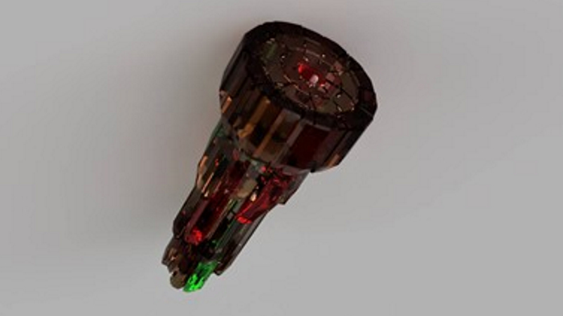
For anyone interested, I've loaded the stls for my Stargate ZPM build here - https://www.printables.com/model/590765-stargate-zpm-build
You can get further info on assembly and parts here:
https://core-electronics.com.au/projects/stargate-zero-point-module/

Printables.com
Stargate Zero Point Module 3D print build | Download free 3D printable STL models
Core Electronics
This one is for the Stargate fans out there. A realistic, 3D printed, light-up Zero Point Module!
I found a model on Thingiverse for a ZPM - It had good detail but - I took issue with the visible seam, and to change the colors of any crystals they had to be painted since it was a single model. I wanted to remix it so it could be printed as a sta...
 signal kraken
My version of an ESP32-S3 Rev TFT Feather Development stand.
More at https://www.kineticprecision.com/dry-filament-campaign
And much discussion on this live session from 24 SEP... https://www.youtube.com/watch?v=NWjTebiChJs


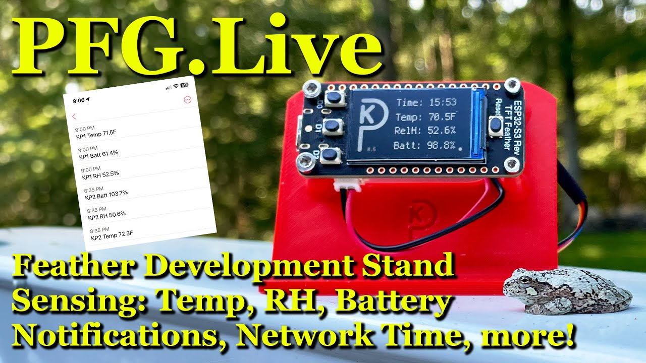
Feather Development Stand - The STL files are in the links page. Super useful for desktop development.
Sensing: Temp, RH, Battery - getting the most out of the SHT4x, and the onboard battery conditioning chip.
Notifications, Network Time, more! - We learn about ntfy.sh and use it for notifications from Feather to Phone. We use the NTP proto...
 exotic sierra
With Christmas practically tomorrow when you’re a person who likes to make gifts, I’ve finished some tiny gameboy type boards to make presents for my two oldest kids


 frosty topaz
exotic sierra
With Christmas practically tomorrow when you’re a person who likes to make gifts...
frosty topaz
exotic sierra
With Christmas practically tomorrow when you’re a person who likes to make gifts...
Will it run doom?
exotic sierra
frosty topaz
Will it run doom?
I think doom can run on an ESP32-S3 lol
frosty topaz
I know, I’m just memeing
It probably would be fun to play doom on those though
Maybe.
exotic sierra
it measures 36 x 60 mm
so 1.4" by 2.35" roughly
there will be a 3D printed case too
so it'll probably be over 1.5" x 2.5"
exotic sierra
frosty topaz
It probably would be fun to play doom on those though
I'm hoping to have the hardware ready early because putting games on it will probably be a bit hard
I'm doing them with no sound because.. well my kids are young and last thing I need is loud beeps and boops lol
frosty topaz
I’d probably design a pad for a 3.5mm myself, just in case…
 wide brook
exotic sierra
wide brook
exotic sierra
You made me use the Santa emoji in September, you old madman :P
exotic sierra
frosty topaz
I’d probably design a pad for a 3.5mm myself, just in case…
not a bad idea
wide brook
Jokes aside, it's a nice and very unique gift idea
Think they'd be interested in programming them?
exotic sierra
my son might be there within the next year or so
teaching him coding might be a good way to get him to learn how to focus on things
wide brook
Is focusing on things something you learn? I (obviously) don't remember anymore (and I've obviously never raised a child)
exotic sierra
wide brook
Is focusing on things something you learn? I (obviously) don't remember anymore ...
in a way yes? It's complicated tbf
some of it is not really controllable (interest, motivation, etc..)
but you can learn how to be disciplined in a task. Though I don't want to teach electronics and coding in a way that feels like a chore.. that's a great way to kill the spark that he has currently
I mostly want him to enjoy it, to find something he can put energy in and get better at as he gets older. something that will either be a fun hobby or potentially something he can use to provide for himself as he gets older.
Added a speaker

plus a PAM8302 for audio
This will probably be the version I make for my brothers.
 last bronze
🤤

 crystal pier
 heady holly
my air guitar. live demo failed on the show and tell live stream 😅
 pallid saffron
Two NeoKey 1x4, some small OLED screens, crazy amounts of NeoPixels, and a nifty minifig (HomeAssistant via HTTP and MQTT for other stuff)

 marble mantle
building new robot...


 night peak
@west zinc @sharp comet Hoping you don't mind, I lifted some of your stream for my intro....
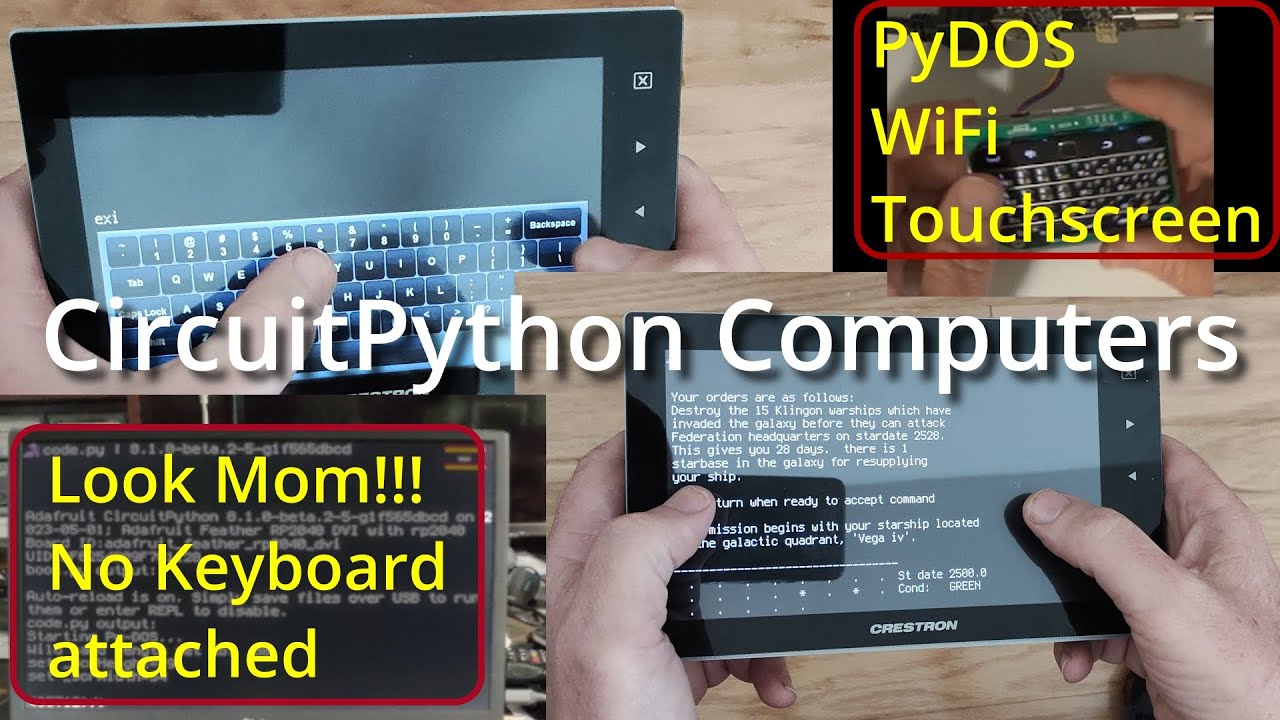
Demonstrating PyDOS, a DOS like shell for microcontrollers running Micropython or Circuit Python, running on the HackTablet. The HackTablet uses an ESP32S3 and gives you a handheld tablet with much of the capability of an original IBM PC.
The Python and Basic code demonstrated can be found on GitHub at
https://github.com/RetiredWizard/PyDOS/
ht...
 sharp comet
night peak
<@366059101203202052> <@382939733107408897> Hoping you don't mind, I lifted some...
sharp comet
night peak
<@366059101203202052> <@382939733107408897> Hoping you don't mind, I lifted some...
don't mind at all. Great to see! Thank you for sharing 🎉
 west zinc
night peak
<@366059101203202052> <@382939733107408897> Hoping you don't mind, I lifted some...
west zinc
night peak
<@366059101203202052> <@382939733107408897> Hoping you don't mind, I lifted some...
Keep it up, like seeing what you’ll do next.
clever stone
clever stone
I’ve been playing around with (and doing some remixing) of Isaac Chasteau’s 3-Ax...
The remixing of the 3-axis camera slider continues. I had it all assembled and then realized, I don't use a traditional camera. I always use my smartphone(s). So I had to extend the "cradle" to handle a smartphone and to deal with the lest being at the very end.
I'm Al's reworking the slider mount to receive the drag chain.

 versed lava
clever stone
The remixing of the 3-axis camera slider continues. I had it all assembled and t...
versed lava
clever stone
The remixing of the 3-axis camera slider continues. I had it all assembled and t...
Good job getting that working - I tried it but didn't have a lot of luck with building the bearing (it worked but was very loud) and ended up buying a pan/tilt off amazon to hack instead.
clever stone
@versed lava - a few things probably helped me get a smooth 3D printed ring bearing.
- My printer is tuned very well now
- A lot of very light sanding to make the inner, outer, and retainer loops smooth _(especially anywhere the BBs contact
- A tiny amount of green bicycle grease (the grease also held the BBs during assembly which was super convenient)
The noise I hear are the servos, not the 3D printed ring bearing.
versed lava
clever stone
<@771166355939786823> - a few things probably helped me get a smooth 3D printed ...
Interesting - I have a much nicer 3d printer now and I definitely tried it when my ender 5 wasn't running so hot anymore. How tight are the gears - any rattle when its stopped/started?
clever stone
@versed lava the herringbone gears are snug. I did not print the TPU version - just the originals using the same filament as everything else.
All the 3D printed parts are in PETG.
 stark latch
A 3D-printed lamp made using 16 LEDs controlled by a Trinket, all running off 6V. Base and light bar can swivel, and each elbow can be tightened to lock it in place. Probably should've used brighter LEDS, but it's a decent proof of concept and pretty good reading lamp.
 exotic sierra
stark latch
A 3D-printed lamp made using 16 LEDs controlled by a Trinket, all running off 6V...
exotic sierra
stark latch
A 3D-printed lamp made using 16 LEDs controlled by a Trinket, all running off 6V...
Looks good!
stark latch
Thanks! It's not quite as pretty on the inside. Some serious cramming of circuitry in the control unit. 😀
 north mural
Very nice and compact design. I would recommend fillet corners. Avoid sharp pointed edges for something you’ll be grabbing to turn on/off the lamp a lot. Box edges can be sharp enough to cut you sometimes. The interlocking joints look great.
stark latch
north mural
Very nice and compact design. I would recommend fillet corners. Avoid sharp poin...
Yeah, it could definitely benefit from some design finesse. I designed it on-the-fly, concentrating on function and printability, and not really paying much attention to form or ease of assembly. If I had to do it over again (which I might), I'd fillet the edges, blend the control box into the arm, and make the wire channels accessible. Shoving a pair of 22AWG stranded wires down those tubes was a serious headache. (see https://www.printables.com/model/606181-articulated-dimmable-led-bar-lamp for how convoluted the assembly is) 😄

Printables.com
A configurable LED lamp with dimmer, a multi-jointed support and a table clamp | Download free 3D printable STL models
north mural
Great modular design too for easier printing. Well thought out. 👍
exotic sierra
I was doing an anxious clean (as you sometimes do when you’re an anxious person) and had an epiphany on how to make the display work on an old project

And it worked
Also thanks @warped siren for the example code you posted to GitHub for the GC9A01 displays
 warped siren
exotic sierra
Also thanks <@352910176736772096> for the example code you posted to GitHub for ...
warped siren
exotic sierra
Also thanks <@352910176736772096> for the example code you posted to GitHub for ...
that's a pretty cool looking little board! what's it for?
exotic sierra
warped siren
that's a pretty cool looking little board! what's it for?
The hopes is a hacker kind of watch. I am planning to write some firmware for the Bluetooth chip to talk to the rp2040.
 rose barn
exotic sierra
The hopes is a hacker kind of watch. I am planning to write some firmware for th...
rose barn
exotic sierra
The hopes is a hacker kind of watch. I am planning to write some firmware for th...
What features do you hope to add to it?
exotic sierra
rose barn
What features do you hope to add to it?
🤷♂️
I mostly want it to sync time over Bluetooth to start
rose barn
I’ve seen hacker watches that do IR Blasts for turning TVs off, BLE scans, and came with suspicious warnings to not deauth Wi-Fi, despite not having a deauther by default
Cool stuff
exotic sierra
I got my first proof of concept board back for my KeyBoy gameboy emulator. It all works except the up button (might be a connection issue 🤷♂️) but overall it’s fun! Currently programmed with a dot chaser game. Might add pong to it as well


What’s interesting is that once the power switch is off, there’s roughly 15 seconds of power left in the capacitors on the power line. Pretty cool
 burnt wyvern
exotic sierra
I got my first proof of concept board back for my KeyBoy gameboy emulator. It al...
burnt wyvern
exotic sierra
I got my first proof of concept board back for my KeyBoy gameboy emulator. It al...
This is so cool! I have a Gameboy keychain that I originally wanted to fit an ESP32 inside of flashed with a Gameboy emulator, but I'm not very good at circuit design.
How complicated was the assembly? Did you solder everything by hand?
 solemn vector
Nice! I am also working on a board that will hopefully fit in a Gameboy shell, and host a Raspberry Pi. The project has been on hold, but I will resume soon.
 burnt wyvern
Wow, that's impressive! That reminds me, I haven't worked on my 3D printable Game Boy shell in quite a long time. This is where I'm at right now, it's mostly 1:1 with the original shell's measurements and uses the original fonts, and is fully compatible with the original DMG-01 game boy parts. The back part is still a work in progress and isn't fully compatible so it's not shown here.
 exotic sierra
burnt wyvern
How complicated was the assembly? Did you solder everything by hand?
exotic sierra
burnt wyvern
How complicated was the assembly? Did you solder everything by hand?
I had assembled with tweezers, placed into solder pasted pads that I pasted with a stencil. I also cooked it in a toaster oven
burnt wyvern
Ah, that would probably be much easier than hand soldering. I didn't realize there was the USB C port before I had sent that as well. (Also that the pads on the ESP32-S3 were underneath the module)
solemn vector
burnt wyvern
Wow, that's impressive! That reminds me, I haven't worked on my 3D printable Gam...
Pretty cool!
exotic sierra
Worked on a case for this prototype

Much easier to play now
I just need to add a hole for the USB cable and make some adjustments to the overall body of it
north mural
I think foamyguy wrote some gamepad code for displayio buttons that might be useful. Being able to recreate gameboys with a 3D printer and some electronics is very appealing!
 cobalt gulch
Christopher Netherton
I purchased 4 of the Hallowing #4300 boards yesterday and was wondering if here was a code sample to synchronize left/right eye movements. Any starting point would be appreciated.
 zealous eagle
cobalt gulch
Christopher Netherton
I purchased 4 of the Hallowing #4300 boards yesterday and...
zealous eagle
cobalt gulch
Christopher Netherton
I purchased 4 of the Hallowing #4300 boards yesterday and...
 exotic sierra
KeyBoy stuff is up on GitHub, still a WIP but a good start: https://github.com/skerr92/KeyBoy

GitHub
Home of all things KeyBoy - Games, board files, parts lists, and more! - GitHub - skerr92/KeyBoy: Home of all things KeyBoy - Games, board files, parts lists, and more!
exotic sierra
Nearly final case, getting fit and feeling right. Final pass will add hole for the usb C plug and make the “A/B” button hole a little bit better shapes


 exotic sierra
Final round 1 prototype


Decided to make a hole for usb with my soldering iron as the display showed signs of separation when taking apart.
 rain charm
Tpu on buttons is cool if you can handle the aesthetics being different
rain charm
exotic sierra
Nearly final case, getting fit and feeling right. Final pass will add hole for t...
rectangle with rounded edges work nice
and rotate 45 degrees
no need for latches then
i doubt tpu will do letter etching at that fidelity tho
exotic sierra
It’s pretty small
rain charm
oh a rocker

i had plans to do a pcb but not sure i can be bothered now - prolly just going to save my money to move house
think i'll just plug my pi to a screen and use a gamepad 🤣
 stray dune
Made this thing that is neatly keeping my workspace tidy while my probes are super-easy to grab whenever I need them:


This probe holder should have its place in any electronics workshop. Keep your multimeter and oscilloscope probes within reach without cluttering your workspace.
This probe holder fastens with two zipties to your magnifying lamp and can hold up to four probes. The holders are designed to allow your muscle memory to retrieve and set aside your pr...
 cerulean granite
Decided i needed a home automation scene controller...
Powered via USB-C... brains are a Shelly i4 DC running on 5V


 prime zodiac
marble mantle
prime zodiac
marble mantle
Did you cut off the text on purpose to be ironic 🤣 Love it!
marble mantle
The idea is not mine. But I did think it appropriate on a ruler
cunning lava
 exotic sierra
cunning lava
exotic sierra
cunning lava
That’s pretty cool!
marble mantle


powered by Adafruit's ESP32-s3 feather with TFT display
which allows me to do nice things such as battery charge indicator in the corner of the screen:
 exotic sierra
I should read the battery voltage on my little KeyBoy so I can display it on screen.

 junior barn
cunning lava
junior barn
cunning lava
Cool! Can you PID it up on two legs?
cunning lava
junior barn
Cool! Can you PID it up on two legs?
no, they are not nearly strong enough to react fast enough
pallid saffron
without access to 3D printing (and getting a little tired of trying to wedge everything into LEGO), what is a frustrated button-box-builder to do?
go "industrial"
swirly-board base, neokey 1x4, 3 OLED (multiplexer), integrates with HomeAssistant and my own stuff over MQTT, uses ToF sensor to change menu options (bottom row only) -- waiting for my next allowance to add a rotor with switch (and neopixel of course) -- powered by a Pi4 with nothing better to do at the moment
 exotic sierra
pallid saffron
without access to 3D printing (and getting a little tired of trying to wedge eve...
exotic sierra
pallid saffron
without access to 3D printing (and getting a little tired of trying to wedge eve...
pretty cool to see one of these in the wild. It looks really good with all the boards you have attached
pallid saffron
exotic sierra
pretty cool to see one of these in the wild. It looks really good with all the b...
i think i've got enough real-estate left on the bottom right for the forthcoming rotor 😈
exotic sierra
hehe
cobalt gulch
@zealous eagle. Thank you. Perfect example for me!
 gilded canopy
Unboxing 22 Sensor Modules Kit for Arduino!
https://youtu.be/TWH011FFa8c

Join this channel to get access to perks:
https://www.youtube.com/channel/UCWtecUwtg_5NmH5UvT3U5Zw/join
Twitter: https://twitter.com/r_tificialintel
DeviantArt: https://www.deviantart.com/imajtitan
ArtStation: https://www.artstation.com/imajtitan/store
Discord: https://discord.gg/M6eTcc7hMU
DHT11 Temperature and Humidity Sensor
HC-SR501 Inf...
versed lava
gilded canopy
Unboxing 22 Sensor Modules Kit for Arduino!
https://youtu.be/TWH011FFa8c
Nice - I found one of these at Microcenter for $5 because it was missing any brand, labels, etc and not all the parts had part numbers on them and I couldn't identify them
gilded canopy
versed lava
Nice - I found one of these at Microcenter for $5 because it was missing any bra...
no local ones here. i'm starting in robotics, building a tracked car
 crimson egret
I had to watch the solar anular eclipse in Costa Rica from a bus. But I was glad that I got some nice data on the weather station that I have working with circuitpython.

As graphed by Adafruit.io.
 slim finch
crimson egret
I had to watch the solar anular eclipse in Costa Rica from a bus. But I was glad...
slim finch
crimson egret
I had to watch the solar anular eclipse in Costa Rica from a bus. But I was glad...
What are you using for the different wavelengths, and have you found the data to be helpful?
crimson egret
That would be Adafruit's product id 4698, the AS7341 color sensor.
And yes, the data has been helpful. It's already being used to mic the sun patterns for growing corals and orchids.
slim finch
That's an awesome application! Thank you! (And ohh I love orchids and plants in general, so that's extra awesome)
north mural
I wonder if a mimosa closes its leaves during a solar eclipse. That would be a cool experiment.
 junior agate
crimson egret
As graphed by Adafruit.io.
junior agate
crimson egret
As graphed by Adafruit.io.
haha sweet
versed lava
gilded canopy
no local ones here. i'm starting in robotics, building a tracked car
They aren't normally cheap - just sometimes you get things for basically nothing when the box is missing stuff or they've been there a long time. Your video helped me identify some of the sensors I couldn't though!
gilded canopy
versed lava
They aren't normally cheap - just sometimes you get things for basically nothing...
Cool I am just figuring things out but having AI now (instead of 2 years ago) makes things so much cleaner! https://youtu.be/sgxPprXqOfA

Join this channel to get access to perks:
https://www.youtube.com/channel/UCWtecUwtg_5NmH5UvT3U5Zw/join
Twitter: https://twitter.com/r_tificialintel
DeviantArt: https://www.deviantart.com/imajtitan
ArtStation: https://www.artstation.com/imajtitan/store
Discord: https://discord.gg/M6eTcc7hMU
Dive into this Intro to Robotics, the fascinating ...
I had a lot of fun building this. great learning platform https://youtu.be/qA648Fs6PXE

Join this channel to get access to perks:
https://www.youtube.com/channel/UCWtecUwtg_5NmH5UvT3U5Zw/join
Twitter: https://twitter.com/r_tificialintel
DeviantArt: https://www.deviantart.com/imajtitan
ArtStation: https://www.artstation.com/imajtitan/store
Discord: https://discord.gg/M6eTcc7hMU
Join me as I unbox and assemble the XiaoR Geek Sma...
 ebon garnet
Hi Lady Ada. I was so excited to see the release of these new round displays and you said you were found to make a moon phase display. So I decided to upgrade my digital clock with one of the RGB-666 Display. Still putting it all together but you get the idea. Here are some picks. Love your company. You've made a retired man happy


 lost leaf
Wanted to share this - Since my stream last week I've been building a graphics library for my BlizzardS3 board, and now that all of the 2D stuff is in, I decided to take it a bit further... all MCU side is coded in CircuitPython of course!
https://www.dropbox.com/scl/fi/kh5n7232f0x92g3t939bl/blizzards3_3d_circuitpython.mov?rlkey=cvzklvhlyehvdtt98v03ylwby&dl=0
 exotic sierra
lost leaf
Wanted to share this - Since my stream last week I've been building a graphics l...
exotic sierra
lost leaf
Wanted to share this - Since my stream last week I've been building a graphics l...
Only thing left to do now is port Chex Quest to it

 gusty shard
I used to play that.
 tepid socket
muKey: A customizable 8-key keyboard.
This software allows you to communicate with any microcontroller to use its digital inputs as keys using transducers (buttons, digital sensors, etc.) (pull-up). In other words, you can transform light, sound, vibrations, etc. into keystrokes. If you know how to use an Arduino development board and the basics of electronics, it's worth checking out.
 gilded canopy

Join this channel to get access to perks:
https://www.youtube.com/channel/UCWtecUwtg_5NmH5UvT3U5Zw/join
Twitter: https://twitter.com/r_tificialintel
DeviantArt: https://www.deviantart.com/imajtitan
ArtStation: https://www.artstation.com/imajtitan/store
Discord: https://discord.gg/M6eTcc7hMU
Thank you to sponsor!
Zagros Robotics: https://ww...
cunning lava
cunning lava
I made a chassis for it.

 north mural
That's cute, love it!
 sonic fractal
My first custom dev board
Its... not perfect
But it was my first attempt, and i learned quite a lot
rose barn
Do you have a write up of your journey?
sonic fractal
rose barn
Do you have a write up of your journey?
Not really
I have some sketches and notes
sonic fractal
It werks
exotic sierra
Working on a cool puck shaped light to use a controller I made a while ago.

Would be cooler if the power cable was black but it’s all I got so it works
This version won’t utilize the ambient light sensor on it but my kids also want one so I gotta order more boards and stuff
exotic sierra
With the diffuser


 rustic dove
Powered by 3x QT PY ESP32-S3s and 2x 128x128 OLED screens. Separate rgb dreadlock hair has 18 different lines going to a Pico W. This is the HELM for my wearable PC project and will continue to evolve over time.

 carmine flare
https://hackaday.com/2023/10/04/2023-halloween-hackfest-flickering-pumpkin-pin-is-solidly-built/
My little Halloween project, and my first writeup on the hackaday blog 🙂
Are giveaways allowed here? I’d love to mail out a few more pins (or kits!) if anyone wants them. First three people to dm me?

Now first of all, [Steph] grants that you can already take your pick of several LED pumpkin badges out there on IO. That’s not the point. The point is that this flickering pumpkin pin is nice…
 lean elbow
Awhile back I saw on Phil B's twitter that you could snip the controller off of some of these LED curtains and use your own custom controller. So I did that. This is running a version of Phil's oozemaster code on a Feather RP2040. I call it "The Blood Wall" (my brother calls it a "screen saver on my closet" 🙄)
 strong storm
I'm synchronizing Neopixel animations to my original music: https://cdn.discordapp.com/attachments/438179968988741636/1165504761026588702/IMG_0254.mov?ex=654717e5&is=6534a2e5&hm=93907d0eee7db513865dd8537fcc3b3113ea8b9d44bbb7cc92d1d106fb2d6ca6&
rustic dove
rustic dove
Powered by 3x QT PY ESP32-S3s and 2x 128x128 OLED screens. Separate rgb dreadloc...
Wore it last night to costume party, though I really need to work on passthrough camera to see out of it better lol. Also the eyes kept crashing for some reason, will get it figured out.

The hair has 18 separate dreadlock strands with 18 separate data lines that I wired myself. This vid is before I got it mounted to the helmet plate part.
north mural
I got the same helmet and had the same idea. I think adding some Noods to places will look cool too.
rustic dove
Ha cool. I haven't tried noods yet but wanted to maximize flexibility on the wiring while minimizing the power cost (also I'm running at ~16% brightness)
and I already had a bunch of WS2812B 144/m strips that I cut up and soldered
the wiring was tough toward the end, and before this year I had never soldered. been quite the learning experience


the hair is 18 strands, 3 sets (left/right/center) of 6 strands with 5 lights each (total 90 lights), and among each set of 6 I have them in 3x pairs in the velcro and ziptie structure I built together. each pair I joined together for their ground and voltage lines, which then soldered onto a 'copper ring' I made out of copper wire so that all of the strands could have flexible wiring to central ground and power rails, which I covered up with electric tape
sonic fractal
Tip for everyone designing a ESP8266 board (this is only for ESP12 as far as i know, other boards may not be like this): in some datasheets and tutorials GPIO2 is shown to be high in some states, this pin unlike EN for example, is not a pull-up and should not be connected to anything. The reason why its high is because its the status led. Which most guides and documents i read didnt even mention
This was me when i removed resistor R3 (GPIO2 pull-up) and the led started working
 lean elbow
In my bedroom there is no light, and the light switch appears to not be connected to anything. I wanted to be able to control WLED and other devices easily, so I built this box to replace the switch cover plate. Didn't want to mess with mains power so it fits right over the original switch. I used a QT Py ESP32-S2 and a Neopixel driver board, and some arcade buttons modded to use Neopixels. Along with an RPI that I'm using as a local MQTT broker, I can now control the lights in my room easily 😄


 pallid saffron
I think I may have a thing about blinkenlights (https://en.wikipedia.org/wiki/Blinkenlights) -- actually, i do have a thing 😎
 lean elbow
Love this! I've long wanted to build a giant panel like the ones in the backgrounds of sci-fi shows that's just hundreds of blinkenlights and various knobs and switches that all maybe do something or maybe are just fun to look at and mess around with.
pallid saffron
my main problem is i don't have enough buttons for all the things, so each row has a rotatable menu plus there's a ToF sensor on the top of the swirly board to literally switch menus on the front row (rotates between 3 completely different functions) -- the top row controls HomeAssistant stuff
sonic fractal
sonic fractal
Tip for everyone designing a ESP8266 board (this is only for ESP12 as far as i k...
hmmm, something desnt add up
 drowsy void
Song: Miami Sky by Karl Casey @ White Bat Audio
I made an Adafruit powdered LED grid and a proprietary game/graphics engine for the LED grid
I have some more impressive games for it these days as this video is nearly a year old
 sullen island
New project, fairly simple but with a lot of learnings:
https://github.com/suarezluis/pico-selfie-light#readme
CircuitPython http server to control a selfie light. (includes API)
 kind burrow
I did a fun project, with thanks/apologies to the Great Liz Clark. Using this guide:
https://learn.adafruit.com/led-matrix-sports-scoreboard/code-the-scoreboard
and broke it down significantly to just do NFL scores for a week - the week # is passed in settings.toml. If you set this to the current week coming up this weekend (it's now 8), it will show the teams that will be playing (with zero scores).
This is one 64X32 board only.
It builds 2 lists with the scores, using json_stream (which is a little slow), then pops up the teams/scores one at a time, with delay between. The pic just shows one.
I did a clone project of this to scroll the results, but it just don't work well and hard to read...
I really learned (after lotsa trial and error) how to use json_stream. The ESPN data received is huge...
I assume that if I run this on Sunday while games are ongoing, ESPN will real-time update the scores. We'll see. Maybe Liz mentioned this, not sure...


 proven coral
For the Qualia ESP32-S3 controller for RGB-666 TFT displays, here utilizing the 3.2 inch 320x820 with touch.
 proven coral
The black ABS looks good, but the display would be more prominent if I used another colour. Should be possible to add a speaker (to be an alarm), and environmental sensors. Light sensor would allow the display to be dimmed, for use as an alarm in a bedroom.
north mural
The Qualia board and larger displays are gorgeous. Slower at full resolution due to all the pixels but will work great for projects that don't need display updates more than 5fps. Anything with slower changing labels will be nice and big with gorgeous image clarity even with 8-bit indexed bmp's. 👍
 meager summit
2 Pumpkins I did for a work pumpkin contest. Using the Monster M4SK for the LED version and using pingpong ball eyes connected to servos for the mechanical version. Used metrominis for servo control and for the neopixel ring fire effects. Also used powerboost 1000's for lipo power management/charging. I named them "Pixel" and "Servo", the Calabaza brothers! Won "most detailed" and won "best overall"!
Video Demo: https://youtu.be/RjcaNtWrw80?si=fSNKVr46Jax3DRcq



2 Pumpkins I did for a work pumpkin contest. Using the Adafruit Monster M4SK for the LED version and using pingpong ball eyes connected to servos for the mechanical version. Used metromini's for servo control and for the neopixel ring fire effects. Also used powerboost 1000's for lipo power management/charging. I named them "Pixel" and "Serv...
night peak
Hacktablet and Makerfabs 7" displays working together 😄 Thanks @north mural !
 north mural
Ohh that’s cool and unexpected. Should be thanking Melissa and Todbot. I only adapted their code. You might be the first to get something like that working on the hacktablet though. 👍
rustic dove
neat, I did something similar recently
night peak
Ready for the little ghouls 😄
 proven coral

 sand grotto
proven coral
sand grotto
proven coral
Got a link to the design?
proven coral
It is on fusion 360, so I could make it publicly available I guess. I generated some renders of the case halves with the Qualia ESP32-S3 board and the 3.2" display with capacitive touch. The front and back faces are 15 degrees off of perpendicular.


 proven coral
I also have a git hub page... I could put the f3d file and STL files of the parts there. What's the GRA (Generally Regarded As) best practice?
There are a number of planes that interface at acute angles that really shouldn't. I think I'd like to fix that with some fillets, chamfers or other steps before I make the design files public. I am perfectly fine with anyone that can reverse engineer the parts from the currently posted information.
north mural
Make a printables account for your STL model projects. Especially if they're to be 3D printed that's the best way to share them.
That is how Adafruit shares their 3D printing project files too. All of their models for learn guide projects are hosted on their printables account.
proven coral
sand grotto
Got a link to the design?
https://www.printables.com/model/634407-clock If you use this, I would greatly appreciate feedback and a look at pictures.

Printables.com
Case designed for Adafruit Qualia ESP32-S3 and 3.2" 320x820 display with touch screen | Download free 3D printable STL models
proven coral
Hardware
25mm long M2.5x0.45mm pan head screws * 2
5mm long M2.5x0.45mm pan head screws * 2
3mm long M2.5x0.45mm pan head screws * 4
 umbral mesa
Hello folks! This is my first time diving into the Adafruit community and my first real maker project. The boo's are run by pico w's and have 3 main modes 1) Angry, 2) Happy, 3) cylon/robot. The controller is also a pico w. I used MQTT protocol and routed network communications through a raspi4 in my packet. I'm considering investing some time in documenting the build and publishing code but not sure how best to approach that or if its worth the time. Hope you like it! Cheers.
short summit
umbral mesa
Hello folks! This is my first time diving into the Adafruit community and my fir...
Very cool! If you do decide to document it, you could use the Adafruit Learn system's Playground: https://adafruit-playground.com/
sand grotto
proven coral
I also have a git hub page... I could put the f3d file and STL files of the part...
Definitely appreciate a github place, it allows the raw process to be recreated. Maybe you'd also like to use the https://www.adafruit-playground.com for a Note / guide.
It's basically the adafruit learn system for everybody, no ads or data sharing and free forever! (My little section, all unfinished: https://adafruit-playground.com/u/tyeth ). You could point to the github there too. Also once your happy with it then you could email it over to the newsletter, and/or the 3d printing brothers (maybe featured on Wednesdays show). See how you feel
north mural
Playground is gaining traction as a good place to document projects and builds. +1 can recommend.
 near ferry
 north mural
Glad to see you got the display mounted right side up this time. 🙂 Does it work well? I think I have that same oven or something similar to it.
ebon garnet
After many hours of reading and testing I finally got the hack tablet I received monts ago to work with CP 9 a-2 OS. the example was set up for RSB666 display using the io Expander which didn't work with a esp22-3 n8r8 board.
north mural
Heck yeah!
 tired crag
Made a nixie clock with a PCB designed by me

Now I just need to make a case for it so I don't get zapped by it (again)
 reef flax
ebon garnet
After many hours of reading and testing I finally got the hack tablet I received...
reef flax
ebon garnet
After many hours of reading and testing I finally got the hack tablet I received...
Did not even know the 'hack tablet' was a thing. That is awesome. Will make for an excellent HMI.
 karmic river
I hope my dog likes it. 🤪

 gusty shard
"A simple clock."

# EQUIPMENT
## Feather TFT ESP32-S3
## Adafruit ADXL343 + ADT7410 Sensor FeatherWing
## FeatherWing Doubler https://www.adafruit.com/product/2890
import board
import displayio
import terminalio
import time
from adafruit_bitmap_font.bitmap_font import load_font
from adafruit_display_text.label import Label
from adafruit_display_shapes.circle import Circle
import adafruit_adxl34x
import adafruit_adt7410
import wifi
from socketpool import SocketPool
from adafruit_ntp import NTP
import rtc

i2c = board.I2C()
display = board.DISPLAY
ax = adafruit_adxl34x.ADXL343(i2c)

pool = SocketPool(wifi.radio)
ntp = NTP(pool, tz_offset=-7.0) # US/Denver
rtc.RTC().datetime = ntp.datetime

def get_time():
    now = time.localtime()
    a = f"{now.tm_year}-{now.tm_mon:02d}-{now.tm_mday:02d} "
    b= f"{now.tm_hour:02d}:{now.tm_min:02d}:{now.tm_sec:02d}"
    return a,b

WHITE=0xCCCCCC
radius = 24
splash = displayio.Group()
cc = Circle(display.width//2, display.height//2, radius, outline=WHITE)
splash.append(cc)
lora14 = load_font("/fonts/Lora-14.pcf")
lora32 = load_font("/fonts/Lora-32.pcf")
label_date = Label(lora14, text="----", color=WHITE, x=8, y=display.height*2//8)
splash.append(label_date)
label_time = Label(lora32, text="----", color=WHITE, x=8, y=display.height*6//8)
splash.append(label_time)
display.root_group=splash

SCALE=10
while True:
    x,y,z = ax.acceleration
    d,t =get_time()
    label_date.text = d
    label_time.text = t
    cc.x = display.width // 2 + int(x*SCALE) - radius
    cc.y = display.height // 2 - int(y*SCALE/2) - radius
    if abs(x+y) < 0.2:
        cc.fill=0x444444
    else:
        cc.fill=0
    time.sleep(0.1)
Wow, glad to see these HACKtablets still making an impact.
clever stone
Several months ago I developed a 50mm touch-wheel using just 3 sensors. It was implemented in “C” and made into an I2C device.
Today I implemented an 85mm touch-wheel using 4 touch sensors and written in CircuitPython.
Even without any smoothing, the range-data is very usable.
exotic sierra
Nearing completion of the final iteration of KeyBoy
 gusty shard
Can I connect an I2S amplifier to the "Adafruit Qualia ESP32-S3 for RGB-666 Displays"? It isn't mentioned in the learn guide.
pallid saffron
i started my new-found hobby 1 year ago -- so here is my current kinetic and LED nightmare (6 servos, 1 stepper, a lot of WS28xx, 2 neokeys, 4 OLED screens, a 14-segment display, a fair amount of technic-like parts)
say hi to the nice folks!!!
https://photos.app.goo.gl/sH5D3EB1d5aDzvJz6

Google Photos
short summit
That’s pretty cool!
strong storm
strong storm
I'm synchronizing Neopixel animations to my original music: https://cdn.discorda...
update, here it is in action (video is too long for an embed): https://youtu.be/lKaeGmBOBTc?si=kb8n0HlqhlK7gLqc
there's a Raspberry Pi with python-vlc to play the music and Adafruit_Blinka/CircuitPython to control the Neopixels. I had some issues because python-vlc needs to be run unprivileged and Adafruit_Blinka needs to be run privileged so there are actually two programs, one web server and one which makes requests

👉 if you want to support what I do, this is the best way: https://ko-fi.com/interlucid 🚀
I built a custom light show using Adafruit Neopixels, a Raspberry Pi, and Python. this is not the final form of the light show but I wanted to share the work in progress at my "Laid Off" show
I got laid off from my full time tech job at Qualtrics on Octobe...
clever stone
clever stone
Several months ago I developed a 50mm touch-wheel using just 3 sensors. It was i...
Finished up the #CircuitPython TouchWheel library, example, and documentation. I have also included the KiCAD footprints for a 50mm and 80mm touch wheel with button.


 gusty shard
Starting firmware upgrade on AirLift shield.

 lucid bloom
I still have a ways to go but this is generally my new pi 5 desk setup, I still have some hardware to add plus lots of software stuff to do. The monitor and terminal are on a ZigBee switch tied to a aqara fp1 so the monitors/terminal turn on if I spend more than 30 seconds in my room and off with 5 minutes of absence.
 night peak
Lilygo T-Deck
rose barn
how did you flash linux on it?
near ferry
rose barn
how did you flash linux on it?
That's not Linux
rose barn
Ah, finally paid attention to the beginning part. still interesting
night peak
Not linux, just PyDOS 😄
near ferry
It appears you made PyDOS, amazing work
 dark cairn
Motorized analog potentiometer for a very weird project.
It's running at 20% speed.
At 100% speed it's just slamming the edges instantly.
I have nicknamed this the "Railgun Potentiometer".
Here is also a clip of it, running full speed:
rose barn
night peak
Not linux, just PyDOS 😄
That's really sweet! I was actually seriously looking at getting one of those until I realized it would just be a microcontroller. having some sort of REPL with commands would be very interesting though 🤔
pallid saffron
dark cairn
Motorized analog potentiometer for a very weird project.
It's running at 20% spe...
this in a very real way reminded me of stage/concert lighthing consoles that would "playback" the sliders when it was automated -- now i want 50 of these things, but have zero clue what i'd do with them all 😏
dark cairn
well, I needed it since digital pots didn't work on that circuit
They are basically very power hungry digital potentiometers.
dark cairn
pallid saffron
this in a very real way reminded me of stage/concert lighthing consoles that wou...
You could make a diy home automation controller or something, and set the pot remotely or manually
It's excellent for this kind of thing
near ferry
Drawing to the LCD with Rust. This is my time doing anything with embedded Rust so it is not much. I am using the example code from the atsamd-rs repository.
pallid saffron
dark cairn
It's excellent for this kind of thing
on the right-hand side here -- not quite as cool, but lotsa blinky lights #show-and-tell message
north mural
Spent about 10 hours printing U-channels for side-lit LED strip. Turned a dark creepy hallway into something a little nicer. Has a PIR sensor so motion activated only.


Printables.com
For wall mounting side-lit LED strips. | Download free 3D printable STL models
lucid bloom
I made a screensaver for my pi 5 desk setup, it runs when I'm not in the room for 5 minutes and then 5 minutes after that it shuts off the terminal and monitors. My plan is to have multiple screen savers. For now I'm just testing with a button.
proven coral
gusty shard
Can I connect an I2S amplifier to the "Adafruit Qualia ESP32-S3 for RGB-666 Disp...
Looks like an I2S amplifier can be added, the link in the final paragraph of the description is to a youtube video where lady ada is showing off the qualia esp32-s3 board with a star trek intro video and playing sound from the video.
gusty shard
More "it can be done" than "how to do it". Guess I'll figure it out.
proven coral
yeah, I'd love to know how they did it as well.
Looks like the i2s pins can be assigned to any of the IO pins, and there are four pins for SDIO, as well as one or two analog pins, you should be able to use the espressif libraries for initializing it and pass those interface pins as needed.
gusty shard
Used the standard black headers this time.
 dark cairn
Have you ever seen a microcontroller board, and thought it's a powerhouse?
Well, if you didn't, this will change that.

s3 n16r8
board pr eta soon
 fathom summit
Wrote a logging function in C which displays messages on my keyboard's screen 🤓
I can "send" messages with logging(ORIGIN, MSG_LEVEL, message, ...);, which will be filtered out (no-op) if ORIGIN's logging level is set < MSG_LEVEL (ie i can log different pieces of code with different levels)
The message is then formatted with a custom set of specifiers i've come up with (message's text is itself a regular format string, that gets passed thru printf)
- Above the line, using:
"[%LL] %M\n"(%LL = level long, %M = message) - Below, it is using
"%LS (%Ts) %M\n"(%LS = level short, %T uptime in seconds) with an empty message for testing
PS: Changing format at runtime feels rather useless so far, i may remove that option
Playing around with strings (specially like this, to tokenize and format) is always tricky and a bit painful, but the outcome is amazing and playing with screens is fun 🙂
 north mural
I prefer to hide all my errors and just pass or continue right over them. They're just speedbumps sometimes. 😛
fathom summit
All "origins" are now set to ERROR as i now the existing code works (nothing should show up unless a critical problem happens)
For future code additions it will be handy tool 🙂
gusty shard
I made my first adafruit-playground page, using I2S with the Qualia ESP32-S3 RGB666 board.
gusty shard
 clever stone
Yesterday, I posted my ePaper progress - a custom RP2040 design with integrated ePaper raw display.
Truth is the PCB was ordered 5 months ago 😳 I feared it would not work and kept putting off assembling it - “fear of failure” stopped me from even trying.
It can be tough to overcome self doubt. Ultimately, I just had to find little ways to trick myself into working on it.
I first assembled the PCB and focused on the RP2040 functionality because it was familiar. Then I tested the custom touch wheel controller. Finally, I tried the ePaper … for the record, it didn’t work first try 😉 (the FPC that came with the display had top contacts and the installation needed bottom contacts)
stark latch
I made a holder for my soldering iron because it's so lightweight, it kept sliding off the bench from the weight of the cord.
 exotic sierra
clever stone
Yesterday, I posted my ePaper progress - a custom RP2040 design with integrated ...
exotic sierra
clever stone
Yesterday, I posted my ePaper progress - a custom RP2040 design with integrated ...
I had similar fear of failure for my first epaper design. My mistake was that I wired the FPC connector backwards lol 😂
 weary night
Ok, I will delete it here and post again in events
exotic sierra
Thanks 😊
clever stone
@exotic sierra - my mistake wasn’t far off!
exotic sierra
clever stone
<@728676724522352733> - my mistake wasn’t far off!
Just for a good laugh, this is how it’s supposed to be

How it ended up
 clever stone
@exotic sierra - I see the three doors that are part of the driver circuit but I don’t see the mosfet. Whose driver did you emulate?
exotic sierra
Mosfet is under the green wire

I copied the one out of the GooDisplays data sheet
clever stone
@exotic sierra - OK. Mine doesn’t look too bad in comparison 😜

The driver circuit is the block in the upper left.
I switched diodes, thinking that has my issue, and the replacements were larger than the originals.
exotic sierra
Oh you used a partially shielding inductor. I used a chip inductor that was pretty chunky but smaller footprint overall
I do like your placement though, nice and clean
clever stone
The bank of caps are so flat they are the same height as the bottom lip of the FPC so the ribbon from the display goes right over them.
exotic sierra
That’s really cool how that worked out. Is this for the next challenge coin you’re doing?
clever stone
The driver circuit is from the datasheet.
exotic sierra
EPD is such a nice low power way to display things
clever stone
The ePaper will likely end up on a different project.
exotic sierra
Gotcha, still pretty awesome to get it working
clever stone
Routing that design is becoming a nightmare.
I will note, I am surprised what CircuitPython synthio can do with a PWM pin 🤔
exotic sierra
Yeah, it’s pretty impressive
I want to do a synth project one of these days, like the little touch electric xylophone
I just need to find the time to design it
clever stone
Looking at your prototype @exotic sierra, I find it rather funny how the various routing rules for the RP2040 ends up making every board look the same.
exotic sierra
Oh yeah, most every RP2040 design I do, looks identical for the core layout
clever stone
Everyone’s RP2040 design looks the same 👍🏼
 hardy veldt
This little environment sensor hub's been running for almost a year now (and uploading externally to adafruit.io and pulling info from Openweathermap), but since then I've gotten into home server stuff so I finally got around to integrating it with MQTT on a central local server and cutting it off from external connections.
Home Assistant pretty much sits in the middle, pulling data from openweathermap (so it's only one API call for all devices instead of per device), publishing pressure data via MQTT for the sensor hub, which publishes its own set of data via MQTT, which can be displayed in Home Assistant or Graphana/via Prometheus.
It's more of an experiment/sidegrade, but this way it doesn't need internet anymore to be useful and I can always VPN into the graphs if I need to see them outside the local network. Also scalable for whatever else sensor projects I might want to do.
 cunning lava
I made a chassis for it.
cunning lava
cunning lava
I made a chassis for it.
Finally had the time to record it walking

 dark spoke
 crystal pier
cunning lava
Finally had the time to record it walking
crystal pier
cunning lava
Finally had the time to record it walking

 topaz cipher
A project I just finished - an underwater sound beacon to aid visually impaired swimmers: https://www.youtube.com/watch?v=7JQlHfV8p6E

This project utilizes the Adafruit RP 2040 board, Adafruit I2S 3W Class D Amplifier Breakout - MAX98357A, and Adafruit Bone Conductor Transducer.
Build tutorial here: https://www.hackster.io/rhammell/underwater-sound-beacons-for-visually-impaired-swimmers-b1aa85

Hackster.io
This audio device enables swimmers with limited vision to safely navigate through the pool using their sense of hearing. By Bob Hammell.
 lapis jasper
topaz cipher
A project I just finished - an underwater sound beacon to aid visually impaired ...
lapis jasper
topaz cipher
A project I just finished - an underwater sound beacon to aid visually impaired ...
Super cool! Can you make a show and tell stream to show it off?
topaz cipher
lapis jasper
Super cool! Can you make a show and tell stream to show it off?
Yes I would be availble for one in the future, how is this organized?
lapis jasper
topaz cipher
Yes I would be availble for one in the future, how is this organized?
They happen Wednesday's at 4:30pm pacific. You can join via a streamyard link that is posted in #live-broadcast-chat right before it starts
gusty shard
Qualia rocks!
 lucid bloom
My desk now has conversational ai, later on a capacitive touch thingy will control the recording instead of the space bar so I can talk to my ai fren with ease. I plan on adding another touch thingy for voice commands. The way it's coded it will work as long as the terminal isn't doing anything so it will work well with a capacitive touch thing
pallid saffron
IT LIES!
crystal pier
It has never thought, so...
lucid bloom
The voice commands will be similar, hold a pad to record audio, let go to run the program which will then launch things on the terminal and or the other 3 screens.
 native ingot
Over a thousand solder joints down, out of about 1700 total...
 rustic dove
and I thought the 600 or so for my rgb hair was a lot...
 inland trout
rustic dove
and I thought the 600 or so for my rgb hair was a lot...
inland trout
rustic dove
and I thought the 600 or so for my rgb hair was a lot...
RGB hair? I'm curious! That sounds great
rustic dove
ha I never got a better video quality of it in use at the LAN party but
posted in here some weeks ago about it #show-and-tell message
inland trout
Very cool!
lean elbow
I just posted a guide to build a WiFi matrix keypad remote on Adafruit Playground! https://adafruit-playground.com/u/squid_jpg/pages/guide-build-a-wifi-matrix-keypad-remote
 gusty shard
Seems like this is the unofficial channel for https://adafruit-playground.com.
"ProtoEngineer's Guide to the Guide" -- I wrote the outline, GPT wrote the meta-guide.
https://adafruit-playground.com/u/dexter_starboard/pages/protoengineer-s-guide-to-the-guide
gusty shard
CircuitPython and GPT Code Interpreter https://adafruit-playground.com/u/dexter_starboard/pages/circuitpython-and-chatgpt-code-interpreter
marble mantle
 vivid yarrow
how large is it?
vivid yarrow
about 80cm in heigh and 6.70cm in diameter. But In my opinion it looks bigger on the video
cedar dew
This is my take on the Westar-35. I added electronics and a sound board with a mini speaker based on one of Noel and Pedro’s projects. Used Circuitpython instead though to trigger the effects
sand grotto
hardy veldt
This little environment sensor hub's been running for almost a year now (and upl...
Love this, similar to what I want, but the convenience of global graphs made me think of publishing agregate data to adafruit IO (dual mqtt publish)
 upbeat lotus
I published an Enclosure for Adafruit 4ch QT Mux 5664 PCA9546 https://www.printables.com/model/658753-enclosure-for-adafruit-4ch-qt-mux-5664-pca9546

Printables.com
Enclosure with lid for Adafruit 4ch QT Mux 5664 PCA9546 | Download free 3D printable STL models
lucid bloom
I got my capacitive touch hat and made voice canmands. Now I get to plan out exactly what I'm going to do with the rest of the inputs and find something better than a can.
pallid saffron
i've used some copper tape as a "pad" for touch -- you can stick it to just about anything
topaz cipher
A project I recently finished: https://www.hackster.io/rhammell/interactive-display-for-finding-wheelchair-accessible-places-6020f1
This interactive display is built using a PyPortal, and shows the locations of wheel-chair accessible places on a map.
The PyPortal makes requests to Geoapify to download a map image, and the Google Places API for data about places, which get plotted on the map.
Users can then touch the map to pull up details for any place.

Hackster.io
This touch-enabled display searches for and maps the location of wheelchair-accessible places around a user-defined location. By Bob Hammell.
Here is the included demo video as well: https://www.youtube.com/watch?v=4iSLRZ3ODrE

 shrewd zealot
Tinkering with the Flipper Zero Wi-Fi module. It can run CircuitPython.
hardy veldt
Made a semi-permanent MQTT-based notification thingy using parts I already have (too many unused boards, too many parts). The original idea involved a feather proto add-on, but LEDs and resistors just take too much space so I opted for the half-size proto instead. XD

 clever stone
Tomorrow I will be demoing a TouchWheel control which uses 4 touch sensors to provide a continuous value from any range. (there is also an example using a wheel made with 3 sensors)
The demo code is written in CircuitPython and the touchwheel PCB footprints are available for KiCAD.
https://gitlab.com/bradanlane_cp/touchwheel
 lean elbow
Made an air quality monitor with a couple of cheap analog displays and some NeoPixels

 near storm
Trained my dog to “speak” using oversized 3D printed buttons. They’re wired to an ancient Raspberry Pi which is running a Python script using the Blinka library. When a button is pressed, it plays the corresponding .wav recording. The output is split and routed to an amplifier (one upstairs and one downstairs) so she can be heard from anywhere in the house. The cat sometimes starts guarding the buttons when the puppy is being “too talkative” 😂
You can buy re-recordable novelty buttons on Amazon, but they cost $10 a piece, have terrible audio quality, have no volume control, and each one requires a battery. I opted to build my own and should be able to support up to 30 words with a single Pi! (Maybe as many as 81 if I extend the number of GPIOs with a shift register.).
Start a thread with your question(s) if you want to know more. Also, I’m considering showing this off on a live show-and-tell, so let me know if you’d find that interesting


 near storm
Flipper Zero Wi-Fi module
gusty shard
I found the glowing mushroom!

 devout verge
I set up an online control panel for the Neopixels on my Christmas tree, and I’m letting my friends and family control it and leave messages displayed on a MagTag ornament.

 glad ruin
Custom Dehumidifier is well underway! This will eventually be incorporated into a filament enclosure.

 north valve
Lots of fun generating AI images for the round TFT display using Qualia.

 nimble sapphire
Hey all! MY writeup about the patch bay from show and tell this week is now up! https://adafruit-playground.com/u/delchi/pages/patch-me-through-to-the-e-4
@topaz cipher do you atten the DEF CON convention ?
attend
north mural


Touchscreen GUI menu for feather weather progressing nicely. Have multiple menu option pages. The left/right arrow buttons go to 3 other pages for content. In total have 8 different pages. It's pretty nice to see what version of circuit python you're running without having to connect it to USB and open the boot_out.txt too. system info is handy.
The touchscreen version of this project is a work in progress. Code available https://github.com/DJDevon3/My_Circuit_Python_Projects/tree/main/Boards/espressif/Adafruit Feather ESP32-S3/3.5 TFT Featherwing/Feather Weather MQTT Touch
north valve
north mural
The touchscreen version of this project is a work in progress. Code available ht...
Great stuff, thanks for sharing. I've been creating some UI with DisplayIO and am curious about patterns for paging display/buttons etc.
I feel like there should be some easier methods for group/tile/paging etc.
In a web browser request for instance, you're not required to unload the previously loaded content.
Thaks again
north mural
Actually a web browser does unload the previous content, that's how you can see the next webpage. It's just built up in a way to make it easier on web designers. There isn't any of that really built into displayio. They do provide a way to add/remove layers (groups, labels, etc..) fairly easily and that's all you really need. I'm all for making the process easier but layouts are more like html templates that expect you do things in a certain way. I'm not using displayio_layouts so I get to customize the GUI exactly how I want. It's definitely a slower and arduous process but in the end you can make everything appear exactly how you want.
One of the downsides is you must wait for any page to fully load before using the menu because the menu must be the top most foreground layer. Otherwise remove/append would throw errors if things half loaded. The more stuff you have on a page the longer the page load time... similar to a web page I suppose. The best method is to use layer[index#] notation so you can insert/load layers exactly where they should be... I'll be working on improving that.
lean elbow
Been working on this escape room puzzle-type-thing for a few weeks using a briefcase I got at the thrift store for 10 bucks, and yesterday got the hardware close to something I would consider final. Now I just have to program this sucker lol. It uses 2 microcontrollers, a FeatherS2 running CircuitPython as the main controller, and a RPi Pico with a DVI PiCowbell running Arduino to drive the 5" DVI display. Other hardware: 2 analog displays, a seven segment display, a 1x4 NeoKeys breakout, an arcade button, a CNC rotary encoder, 8 on/off switches, an electret mic, a PIR sensor, a speaker, two potentiometers, a 3x4 matrix keypad, 10 TRS jacks, and 31 NeoPixels. It also has a 32KB FRAM breakout and an RTC breakout. Powered by a Powerboost 1000c and a big honkin' 10050 mAh LiPo battery.


 scarlet lagoon
Big ups to the Adafruit docs and ChatGPT for letting me cosplay as someone who knows python 😄
(christmas tree light WIP using a RP2040 and circuitpython)


 north mural
Nicely done with asyncio.
scarlet lagoon
Thanks, it could definitely use a bit of cleanup, but it seems functional enough (for this year at least)
I also ended up changing up the button code logic up a bit so that instead of triggering on event.pressed, it now instead triggers on event.released, as I decided to add a check for a long press (I found setting a variable on press, and then on release checking to see if the time since was greater than > 0.6s, worked pretty well, but I'm sure there's better ways). I now use the long press to freeze the current animation instead of having my apartment look like I'm hosting a rave 24/7.
(we're not going to talk about the fact that I had written out code for blinking the button LED as a "notification" when a press was registered + on startup/shutdown, but during assembly I forgot to wire the LED to a GPIO, so now it's just always on) 🙃
clever stone
The MXC4005XC 3-Axis accelerometer supports a configurable interrupt to detect orientation changes, tilt, and shake.
I finally took some time to update the MXC4005XC.py #CircuitPython library to support using the interrupt.
It's very responsive!
Here is the code (MIT licensed 👍🏼) https://gitlab.com/bradanlane_cp/libraries
 devout verge
Third year of my music synchronized holiday light show. This time it's controlled by a Raspberry Pi Pico W, syncing time with a websocket server to the audio player on my website.
https://youtu.be/xdUF-eeLZtQ
Writeup on my website: https://kyleplo.com/projects/lights2023

Writeup for this project is on my website: https://kyleplo.com/projects/lights2023
Songs:
00:00 Sleigh Ride - US Navy Band
2:45 The Twelve Days of Christmas - Love to Sing
6:58 I Have a Little Dreidel - E's Jammy Jams
8:50 Jingle Bells - scottholmesmusic.com
11:21 We Wish You A Merry Christmas - Audionautix
12:17 Deck the Halls - Jingle Punks
Hi, I'm kyleplo, a student programmer who makes random stuff on the Internet.
 solar yew
not as cool as other projects here but here's the latest thing I hacked together in FL studio https://open.spotify.com/album/4F56HaEWbgkCQ85X4KB3K4
😀
kind burrow
With thanks and apologies to Liz Clark... I modified her project code for my display: it's a 2.8" Touch shield product 1651 on Metro ESP32-S2.
https://learn.adafruit.com/qualia-s3-space-clock/code-the-clock
It's only showing earth time, I took out Mars, and will probably do another version with mars that will use touch to toggle. This was pretty easy to do, as Liz's magnificent code really didn't need much modifying.
I resized down the bitmap. Hug report to Liz!

 gusty shard
What's he up to now? https://chat.openai.com/share/ce5e8532-2840-43e3-9e18-f4bf87b901a5

A conversational AI system that listens, learns, and challenges
west zinc
Say goodby to chromatic aberration- This is only “tell” for now, but I just ordered a Memento and will try and hack it to make a pinhole camera like this: https://spectrum.ieee.org/amp/a-digital-pinhole-camera-2663921725

ieeespectrum
Explore lensless photography without the hassle of film
kind burrow
Update code file for Liz Space Clock. I hope she don't mind me ruining it 😀
Earth only. Still not getting Mars to work, maybe tomorrow...
Had to finagle the 6 and 12 positions so they fit in a square display. Sorry Liz...
 upbeat lotus
I designed an enclosure for the neopixel 24 ring. 😄
The idea now is to glue the lid in place, but I am waiting on my clear fillament to arrive -- this is just a prototyping run.


This was an earlier print of the body, but they do work 🙂

 dense swan
I made a zenodo repository with feeds and speeds for printing simple gold and copper circuits on ceramic substrates using nothing but wire, and a cheap desktop 1610 minimill.
https://zenodo.org/records/10391990
it even has a matching youtube playlist of all the experiments for which data was collected:
https://www.youtube.com/watch?v=KyeUkftrFqw&list=PLxlbqMdRe6OVbtT3ehHzCJgsyfsY8-2mJ&ab_channel=Rotoforge
thought the people here might find this interesting.
Zenodo
This repository is for data for an upcoming paper that presents work using micro friction surfacing for applying in-situ maskless metallizations and robust seed layers for electroless plating on demand to substrates like, aluminum oxide, aluminum nitride, and as fired LTCC, for fabrication of next generation power module and other high reliabili...

This is a playlist of my attempts at friction surfacing various metals on various ceramics to produce electronic devices. This is a dataset for a future publication and it is provided under an AGPL-3 license, and CERN open hardware license.
The experiments were all run on a 1610 genmitsu minimill with a 30,000 RPM dremel rotary tool installed ...
proven coral
I've got a tell... The EYE on NPI from two weeks ago, Lady Ada was talking about the TMC5240, released by the new owner of Trinamic, Analog Devices. I've designed, but not tested, a development board for the chip that includes support for the Single-Wire daisy chain feature, as well as Encoder, End Stops, and Analog input. The PCB is 2.4" by 1.4" with four holes for #5 or M3 mounting screws. The daisy-chain feature is intended to be accomplished with 2x7 right angle pin headers and pin header sockets, but also possible with ribbon cable. There is a 1-wire libary available for the arduino that looks like it works with the ESP 32 chips, and I was thinking that the Qualia ESP32 board, one of the various touch enabled RGB screens that Adafruit is selling, with four or five steppers controlled by the TMC5240 might be an interesting 3d printer controller.
The TMC5240 builds on the silent stepper and sensorless end stop features of the original silent stepper controller. First interesting feature, instead of a step and direction pins as input to the chip, you pass movement commands via SPI or Single-Wire. The Single-Wire interface includes the ability to have a number of these controllers attached to a bus, and even have the devices daisy chained. Second interesting feature, you have encoder inputs to the chip, for closed loop functionality. Third interesting feature, motion control is offloaded to the chip, and this is helped out by the encoder input in the second feature. Fourth interesting feature, there is a 12 bit AD converter (admittedly only 1.25V sense range) included in on the chip that can be polled via the SPI or Single-Wire interface. Logic voltage operates from 2.2 to 5.5, so it can run from a 3.3V board, but also compatible with a 5V system. Motor voltage from 4.5V to 36V.
Now, to apply CC-NC, and upload the files from KiCAD to Github.
pallid saffron
upbeat lotus
I designed an enclosure for the neopixel 24 ring. 😄
The idea now is to glue the...
if you want to get it apart later, hot glue works well
 tidal anvil
 upbeat lotus
Progress--detects movement to turn on the light.
 tidal anvil
The walls come in as you get a higher score. Then the backstop gets closer. Once the backboard comes to about 50%, the outer walls recede, then once they get to their original positions, the backboard just comes closer to the paddle until you die since it becomes basically impossible once the backstop is too close. But that's a win 🙂
 ocean osprey
Thats cool!
north mural
Added TFT brightness preference, adding new features every week. Camera doesn't pick up how dim the lowest setting is, can barely see it. Should be good for power savings when on battery power during power outage (hurricane).
Uses @languid nebula circuitpython_slider widget for brightness control. Must have a TFT capable of changing brightness via PWM.
ocean osprey
your own weather statuon?
north mural
This is a new touch version of it though, work in progress. https://github.com/DJDevon3/My_Circuit_Python_Projects/tree/main/Boards/espressif/Adafruit Feather ESP32-S3/3.5 TFT Featherwing/Feather Weather MQTT Touch
ocean osprey
Very cool project!
 upbeat lotus
Made an enclosuer for the Adafruit Seesaw I2c neopixel driver -- this is the first device I couldn't get to work my 2meter I2C cables -- seems it needs a short cable between the MCU and the seesaw even though a long cable will work then between the seesaw and a sensor + neopixel ring.
 ocean osprey
Nice, designing your own 3d printed stuff feels awesome
upbeat lotus
Yeah, using Fusion 360 and getting better at it but its still annoying when compared to how helpful GPT is haha.
ocean osprey
I frankly don't trust gpt, I think its better to learn these skills yourself
upbeat lotus
I mean its a huge productivity boost -- I graduated from UIUC with honors in 2008 and I've worked in software web systems since then, and I get way more done now -- its like a hammer, you wouldn't install nails the old way once you understand the hammer -- you can still get hurt by it, but its quite useful.
I would love if the autorouting PCB capabiliteis actually got smart from the modern AI
ocean osprey
It's more like a lathe, immensely useful but liable to hurt you badly If you use it without knowing what you are doing, and that's the problem
upbeat lotus
Sure, but a tool none the less.
ocean osprey
But this isn't the place for this kind of discussion, good on you for learning stuff too though
 earnest flax

Making MIDI Music with Raspberry Breadstick
Learn how to turn your Raspberry Breadstick into a musical instrument!
Update 3 of Raspberry Breadstick Campaign
For code and example please see update in link below.
https://www.crowdsupply.com/breadstick-innovations/raspberry-breadstick/updates/making-midi-music-with-raspberry-breadstick
You can ...
gusty shard
Wow that's amazing!
earnest flax
gusty shard
Wow that's amazing!
Thanks!
north mural


Adafruit Feather M4 Express + Airlift Featherwing directly to a Matrix Panel. No matrix portal or RGB featherwing required. https://gist.github.com/DJDevon3/7166ebd87c9122e23d8de6d4a2cb605d
Contacts OpenWeatherMap and displays the temperature on the matrix panel. A simple demonstration that you can wire up microcontrollers directly to Hub75 Matrix Panels without needing to purchase a Matrix Portal M4 or Matrix Portal S3.... if you're in a pinch.
 north mural
Beautiful design too. I don't think people get enough credit for nice enclosure designs... as if enclosures somehow just magically appear.
tidal anvil
north mural
Beautiful design too. I don't think people get enough credit for nice enclosure...
This is the Adafruit PyGamer kit, so I guess props goes to them 😛

 north mural
Replicated an M4 Matrix Portal using a Feather M4 Express... kind of. Updating the code with OpenWeatherMap's 2.5 onecall API.
ocean osprey
Awesome!
near storm
I added a socket for a XBee to my flipper expansion board! Now I can use the terminal app to type commands at a raspberry pi… very, very slowly 😅

Made my first matrix keyboard! It’s for increasing the number of puppy buttons that can be supported from a single Pi 😂
Somehow it figures that my first custom keyboard is for my dog
 gusty shard
Music box, gift for a friend.

Feather RP2040, Crickit board, amplified speaker and battery in a wooden box.
https://gist.github.com/rsbohn/dee4ef7191360ff9061cfa570210bd96
lean elbow
Speaking of gifts, just finished building a couple of 8x8 WLED displays for my brothers
ocean osprey
oh these are sick
exotic sierra
Getting some sound going on the KeyBoy gamer
Also thanks to @cunning lava for making your pew pew games open source because that pew is from your pew pew games. It’s a great game
cunning lava
exotic sierra
Also thanks to <@351136009922019331> for making your pew pew games open source b...
I generated it with sfxr, iirc
exotic sierra
oh okay cool, I need to save that link
I need to make some cow and 'yeehaw' sound bytes for my Loose Cows game
 pallid forge
exotic sierra
I need to make some cow and 'yeehaw' sound bytes for my Loose Cows game
pallid forge
exotic sierra
I need to make some cow and 'yeehaw' sound bytes for my Loose Cows game
are you using arcada
exotic sierra
I’m not
upbeat lotus
I forked the pico-serprog project because neither the stacksmashing repo or another prominent fork I found actually worked fully. It took me a few full days, tried experimenting with pio but could never get that to work right, but discovered neither version implemented all serprog comamnds. So in the one that kind of worked I could backup small packets but not the whole rom. Well I just got it working by implementing commands that tell the flashrom the max limit of read/writes and it then chunks them rather than me trying to chunk them (which never worked).
Found Unknown flash chip "SFDP-capable chip" (16384 kB, SPI).
===
This flash part has status UNTESTED for operations: WP
The test status of this chip may have been updated in the latest development
version of flashrom. If you are running the latest development version,
please email a report to flashrom@flashrom.org if any of the above operations
work correctly for you with this flash chip. Please include the flashrom log
file for all operations you tested (see the man page for details), and mention
which mainboard or programmer you tested in the subject line.
Thanks for your help!
serprog_delay used, but programmer doesn't support delays natively - emulating
Block protection is disabled.
Reading old flash chip contents... read_flash:  region (00000000..0xffffff) is readable, reading range (00000000..0xffffff).
done.
write_flash:  region (00000000..0xffffff) is writable, writing range (00000000..0x03f1ff).
W(0:3f1ff)write_flash:  region (00000000..0xffffff) is writable, writing range (0x050000..0x218eff).
W(50000:218eff)write_flash:  region (00000000..0xffffff) is writable, writing range (0x350000..0x967fff).
W(350000:967fff)Erase/write done from 0 to ffffff
Verifying flash... serprog_delay used, but programmer doesn't support delays natively - emulating
read_flash:  region (00000000..0xffffff) is readable, reading range (00000000..0xffffff).
VERIFIED.
serprog: Output drivers disabled
Try it out if you need a rom programmer but only own a bunch of picos, like me: https://github.com/opensensor/pico-serprog

GitHub
Fork of https://codeberg.org/libreboot/pico-serprog - GitHub - opensensor/pico-serprog: Fork of https://codeberg.org/libreboot/pico-serprog
tidal anvil
exotic sierra
I’m not
Why not, only curious.
exotic sierra
tidal anvil
Why not, only curious.
Because I’m making game templates to hopefully start teaching my kids to code in circuitpython
tidal anvil
Ohh somehow forgot circu
lucid bloom
I got myself something hackable for Christmas. https://www.amazon.com/dp/B0BQ716ZS9 usually $150, I managed to add a mpu9250 and a picam v1.3 instead of the 480p cam it comes with, eventually ill pan tilt the picam. I bought some xh254 wires because thats what the kit uses and it has 2 unused 4 pin ports so I turned them into i2c ports. The goal of this project is to learn ros2.


Raspberry Pi Tank: Embark on an Infinite Programming Exploration Journey The Raspberry Pi Tank is a programmable intelligent tank based on Raspberry Pi. It has various advantages such as multifunctionality, open-source design, and ease of programming. It can be used in various fields such as expl...
ocean osprey
sounds fun, i built a little rover out of cheap parts with a pant tilt pi camera and that was fun
im actually working on a second revision
 lucid bloom
The goal is always to have fun and learn stuff 🙂
ocean osprey
exactly

case in point, first motor mount

updated stronger mount lol
you can see how i went from a bare minimum design to something with some heft
lucid bloom
I think 3d printing is going to come in handy with my robot. I can print a new top side that mounts into the existing holes and will open up a lot of possibilities
lucid bloom
I do openscad and that's about it
ocean osprey
i mess around with fusion360
designing parts for your robot will definately feel cool
lucid bloom
The software the robot comes with is garbage and it's missing parts on GitHub so I decided the only thing I'm using of theirs is the hardware
ocean osprey
that seems more fun to me
lucid bloom
Definitely it's running ros2 humble
ocean osprey
mine is running some rubbish i put together 😄
lucid bloom
My previous pi experience has come in handy with the hardware/software so far. I started learning ros2 about a week ago. I can get other people's code running but that's about it, at least for now
ocean osprey
for mine the brain for some of it is an esp32 huzzah, then theres a pi for camera, the plan is to make the pi talk to the esp32, maybe?
lucid bloom
I don't know what the end goal is, I may end up going beyond the empty slots and replace the sensors in the kit with other sensors
ocean osprey
the thing is with somethign like this is you can use it as a platform for all sorts of things
lucid bloom
The interesting thing about this kit is it can use 4 different boards
https://category.yahboom.net/cdn/shop/files/4WD-ExpansionBoard-Yahboom-7-_6_1100x.jpg

 eternal maple
Just wrapped up a helper class to create complex synthio.waveform (wave table) objects from a simple list of fundamental and overtone oscillator characteristics. Coming soon to a CircuitPython Community Bundle near you. https://adafruit-playground.com/u/CGrover/pages/wavebuilder-construct-a-synthio-wave-table-from-a-list-of-oscillators
 gusty shard
left handed bolts instead of right?
ocean osprey
not exacvtly, the bolt blocks the shaft entirely
have shifted the bolt hole, 12 hours of printing and boom ill be sorted...


 ocean osprey
oooo
 main loom
Such a confidence boost.
The buttons are all wrong, but that's just because I haven't remapped them from the test rig.
But it WORKS

No fancy libraries because I don't have the RAM, juggling raw SPI commands, my first board assembled by the factory, my first time using a boost circuit, and, it worked!
main loom
It's a tabletop gaming counter. Track health, experience, and gold. The code is currently unfinished as I wanted to see if the hardware would actually work right before getting into some of the more interesting functions. What I hope to add right now is the ability to at least save the values to EEPROM as well as optionally pick and choose which stats to track from a small list.
The selection of the ATTiny85 to drive it was partly because I had a few on hand, and partly as an excuse to avoid using premade libraries. That's only a 128x64 display, but it still requires 1KB of RAM for a frame buffer. The 85 has a mere 512 bytes.
Fortunately, if you don't mind directly driving the display, you don't technically need any buffer as the display has its own RAM.
There's also an IO expander under the display as obviously I didn't have enough pins for everything.
ocean osprey
Thats cool!
I did programming on the arduboy and thought 1 ish kb ram was constraining
north mural
Very nicely done. Congratulations on a successful PCB!
Very impressive using an ATTiny! I can barely do that with a Pico.
main loom
The board was almost a failure for at least two reasons. First, I failed to read all the specs that I got for the boost circuit design from TI. At a minimum the inductor is under rated compared to what they specified.
Second, the ATTiny85 spec sheet lists SPI pins, but it's not until you read deep into the spec that you find that they're "backwards". This is because the 85 doesn't have SPI except for programming. So I had to cancel the first order and redo it.
last bronze
main loom
Such a confidence boost.
The buttons are all wrong, but that's just because I ha...
are you considering adding a brightness controller? It might get annoying during long sessions at night 😛 look cool overall tho!
main loom
I'd have to look into the display spec for that, but it would be something to think about for sure.
spring pulsar
That is really cool. Are you printing a case for it?
last bronze
in theory if the display doesn't have it in spec you could just use dimmer colors in "night mode" or something
main loom
Probably no case, the buttons are rather close for that, and the switch is a bit small.
Unfortunately, I didn't pick these colors. It's a 1 bit display. The only reason I get two colors is because the first 16 rows are yellow, the rest are blue.
last bronze
I wonder if it could be used as a virtual dice too 😛
last bronze
main loom
Unfortunately, I didn't pick these colors. It's a 1 bit display. The only reas...
ahhh
spring pulsar
I had that same thought about the dice. With a menu button, so many options...
main loom
There's a shift button too, currently kind of planning to make it do +/- 10 instead of only 1.
Odds are if I plan for anything like a case, or really advanced options it'll be the second revision where I plan to use the ATTiny1616 instead.
2KB of RAM, proper peripheral support, plenty of IO pins for buttons. Absolute luxury compared.
last bronze
I smell a nice tabletop gadget for sale 😛
spring pulsar
I've always wanted to build something like this, that I could toggle through games and it would track what I needed for each
last bronze
you could make some sort of rfid cards that would trigger certain profiles for each game
spring pulsar
I've done some of that with the MacroPad I got
spring pulsar
last bronze
you could make some sort of rfid cards that would trigger certain profiles for e...
That would be cool
main loom
With 512B of EEPROM, it definitely has the space to save multiple games worth of stat settings.
spring pulsar
Or a barcode scanner and scan the game
last bronze
maybe you could try to make it in the format of a raspberry pi pico HAT
would unlock so much potential
main loom
A whole new adventure in programming there. I've never done anything for the Rpi type systems.
last bronze
so much fun around the corner 😄
the HAT format would make it easy for people to make at home if you ever publish the schems
whiiiiich could increase the contributor count 😛
main loom
Heh.
One thing to note is that the current design uses a preassembled display my coworker gave me that he got on Amazon. So it's just stuck on a female header.
last bronze
but for rev 2 I'd suggest using some sort of a usb-charged battery
main loom
It would be cool to have the display properly integrated onto the board.
last bronze
cause regular AA are kind of inconvenient in these days 😄
main loom
Perhaps. I didn't want to really deal with lithium management quite yet.
Though it shouldn't be that hard as long as I'm not trying to do things like solder the batteries directly.
last bronze
there are plenty of designs online too
main loom
That too. I mean, it's not like I designed the boost circuit I'm using anyway. I just threw numbers at TI's power designer and used that.
Which I'm happy I didn't mess it up too badly. The original spec called for an inductor with 192 mohm resistance, and rated for 1.5A.
The one I used has 600 mohm resistance, and is only rated for 50mA. Oops.
Fortunately the design was only drawing 20mA when I checked with the USB power meter.
ocean osprey
The display reminds me of one i used for a little project
Let me see if I can find it

This but with a couple of buttons attached

An isopod tamagochi
More an excersise in programming but hey
main loom
Learning by doing, even if the end product has no practical use. As long as you had fun or learned, it was a success.
ocean osprey
thats the way i look at it
i approach every little idea as an avenue to learning something new or getting better at something i can allready do, even if the end product isnt useful
or in the case of my current project, an actively terrible idea
 late kraken
After much learnings, I got 2 matrix 32x32s working as a single display with a label and a pixel grid showing! Matrix Portal S3
ocean osprey
Nice, love led matrix..es? Matrices? Matri?
late kraken
now to get a 3d printed bracket started and then some status display code for the home network stuff
stark latch
late kraken
After much learnings, I got 2 matrix 32x32s working as a single display with a l...
Many, many years ago, I worked for a company that made LED matrix signs for the Toronto subway platforms. The LEDs were all red (blue didn't exist yet and green barely worked at all), and the signs were driven by Z80 processors. The refresh rate was pathetic, leading to weird side effects when you wanted to do any animation (e.g. horizontal scrolling would result in the graphics skewing left or right). Love seeing how far the tech has come since then.
north mural
Just a short demo of the new loading screen for Feather Weather. It shows a text label of what is loading in the background. Don't know why but it reminds me of something for Linux... but it's all Circuit Python. Happy Holidays everyone. https://www.youtube.com/watch?v=ohGwM66MT4k

Just a demo for a newly designed loading screen for Feather Weather with touch display capabilities. Coded with Circuit Python https://github.com/DJDevon3/My_Circuit_Python_Projects/tree/90c2e67a804c648e7c1014e54ed50e851645bdd6/Boards/espressif/Adafruit Feather ESP32-S3/3.5 TFT Featherwing/Feather Weather MQTT Touch
upbeat lotus
Got my LoRa radios working tonight ... not sure why I couldn't get the feather version to talk to one of these but that was also days ago, I should try again now that I got these working together (still need to install the antennas, but wanted to check range without first -- not far).


Unrelated: Earlier today I finished my v1 prototype of this pocket detector project I have been helping to prototype and sending to client in the morning. It uses neopixel 24 rings, seesaw drivers and ADXL acceleromters and an 8-channel mux. The next iteration will not have a centralized MCU or mux -- but rather each detector will be more encapsulated.
north mural
feather version on the same frequency? I've mostly been using RFM Featherwings with RP2040 Feathers (before they made the RFM Feather). Those all work well together nicely. Actually haven't tried using the RFM Feather yet or I might have some advice. Project looks like it's going very well!
The pucks look fun to play with. What is a pocket detector?
upbeat lotus
Yes same frequency -- put the antenna on last night and its been communicating all night from the kitchen to the upstairs here. Pocket detector like for billards to detect a ball entering the pocket
This is the feather M0 Express
I think I was doing something wrong with these radios last time because I just got the Feather M0 reporting in to the receiver as well.
 north mural
Fair. I think LadyAda mentioned when they first came out that a dedicated module or featherwing version can perform slightly better than the built in RFM Feather depending on what Feather you use with it. I typically use S3's so that would perform better with a module/featherwing than the RFM Feather RP2040. Since you're using PIco's the performance should be about the same as the RFM Feather. Making good progress.
Pocket detector for a pool table would be a neat way to automate scoring? I honestly don't know much about billiards.
 gaunt spade
I made my own james webb space telescope!
it cycles through a set of ~100 images taken by the actual space telescope, and displays them on the screen
north mural
That is gorgeous. Looks like you put a lot of time and thought into it. Congratulations. It's stunning.
gaunt spade
Thank you 😁
rose barn
upbeat lotus
Got my LoRa radios working tonight ... not sure why I couldn't get the feather ...
I was under the impression that running radios with an antenna is usually a very bad idea, but perhaps it's different for lower powered ones. Very cool though! I know I was unable to get a nRF52 feather + LoRa radio wing to communicate with others. I think it was a problem with the nRF52 firmware, as switching it to an ESP32 feather made it work almost instaneously.
upbeat lotus
From the product sheet:
Our initial tests with default library settings: over 1.2mi/2Km line-of-sight with wire quarter-wave antennas. (With setting tweaking and directional antennas, 20Km is possible).
Adafruit sells matching antennas.
ocean osprey

Random tip I got from tested, whiteout/tippex markers will write easily on 3d prints and most surfaces which are fantastic for labelling various features
north mural
upbeat lotus
From the product sheet:
> Our initial tests with default library settings: over ...
Keep in mind Adafruit has access to the roof of their building for such tests. If you do it on ground level your line of sight is still literally line of sight. There is almost no scatter. If you want increased range ask your local municipality to lease space on a tower... a roof... or find a really tall tree with good line of sight.
ocean osprey

a modelling excersise, modeling the negative space within a hinged joint
otherwise known as "just model the hinge joint and boolean cut the body to get this with less effort"
but it was fun trying to work out what the empty space in a hinge would look like
lets print it and see
reef flax
My new years resolution is going well, i finished a project! 😮 My house is modern and has no fire place and I wanted one. So with an old cast iron fireplace from a friend, some scrap wood and some fancy small tiles, I made this. Really pleased how well it came out.
 ocean osprey
oh looks nice
my negative space modelling excersise worked perfectly

used it as a tool to cut hinges into a flexible shaft
reef flax
And the hole is the exact same size as a 24.5" monitor. 🤔
ocean osprey


quick single hinge test piece
i was going to ask if you are going to put something in the gap
reef flax
Yes, wanted to make it first and be sure it looks good before buying a monitor. That is the next stage. There is a hidden shelf behind the fireplace which has the plugs and my Nintendo switch on. So have some room to play with.
Most importantly the wall behind has not been touched, so easily removed leaving no damage.
ocean osprey
nice!
burnt wyvern
I made a little motion activated bird feeder camera! This was a Christmas present for my mom, but I spent a couple weeks finalizing the code and stuff to make sure it could run on it's own without maintenance. It senses when a bird is on the feeder using a PIR motion sensor and takes a couple photos and one video, then uploads them to my Dropbox folder where they can be viewed from anywhere. It also only takes photos from dawn to dusk, so it will only take photos when it's light enough to see the feeder.
Here are some photos and videos taken recently with it, along with some photos of the thing itself:


 ocean osprey
Thats very cool
 flint sapphire
Should be done printing all the parts today and my hope is to be done painting by the end of the week.

 burnt wyvern
ocean osprey
Thats very cool
burnt wyvern
ocean osprey
Thats very cool
Thank you!
near storm
When is the live show and tell again? And what do you need to do to join?
short summit
near storm
When is the live show and tell again? And what do you need to do to join?
It is 7:30pm EST on Wednesdays. The Streamyard link to join the show is posted right before the show starts in #live-broadcast-chat
flint sapphire
All done!

 flint sapphire
2 days and one spool... it's gonna be 3 maybe 4 spools total when done
 ocean osprey
That is certainly a project, who is it?
 broken rain
Just posted this and wanted to share it here: https://www.printables.com/model/710536-adafruit-braincraft-hat-cover-for-pi-5-official-ca
 broken rain
also just posted this one: https://www.printables.com/model/710601-pi-5-official-case-active-cooler-insert-small-came

 tawdry meteor
https://arcade.makecode.com/S93427-59091-39613-44864
Made a number based Mastermind/Wordle clone for my Pygamer. lol
 autumn egret
I wanted to speed up my video editing in Premiere Pro, so I used a QTPY RP2040 and a digital encoder to build a video editing knob. Here's the video https://www.youtube.com/shorts/OETrs0F80ZI
 autumn egret
I wanted to speed up my video editing in Premiere Pro, so I used a QTPY RP2040 a...
autumn egret
autumn egret
I wanted to speed up my video editing in Premiere Pro, so I used a QTPY RP2040 a...
And here is the code: https://github.com/Wake-Hydro-LLC/the-knob/tree/d46f4296bfd599582b9ea82b9b6dadec51ac05a3/PLAY HEAD

GitHub
A digital encoder knob for video editing with QTPY RP2040 - Wake-Hydro-LLC/the-knob
earnest flax

Get yours here:
https://www.crowdsupply.com/breadstick-innovations/raspberry-breadstick
https://www.breadstick.ca
Documentation:
https://github.com/Breadstick-Innovations/Raspberry-Breadstick
https://circuitpython.org/board/breadstick_raspberry/
As seen on:
https://www.tomshardware.com/raspberry-pi/good-raspberry-pi-pico-boards-are-hard-to-cru...
clever stone
I need a down-facing camera for streaming and tutorials. I have tried (and DIY’d) many options. The key is to have the camera and the subject matter “linked” so it is always framed correctly.
Now I need the solution to be lightweight and portable so I 3D printed this design.
exotic sierra
clever stone
The most elegant solutions are sometimes the simplest. Nicely done
clever stone
Thanks. Now to test it with Discord, OBS, etc.
clever stone
Have you ever thought it would be cool to have a laser engraved laptop but would never consider laser engraving a laptop?
I bought an Amazon Warehouse shell for my MBP. It has a scratch on the inside (likely why it was a return). The scratch would catch light and be very obvious. This gave me an idea.
I laser etched the inside of the shell. Depending on how the light catches it, it will have a subtle to very obvious effect.
 clever stone
Not being one who can leave well enough alone … I was noticing how well the Apple logo shown through the shell and thought, “I wonder…”

 flint sapphire
clever stone
Have you ever thought it would be cool to have a laser engraved laptop but would...
flint sapphire
clever stone
Have you ever thought it would be cool to have a laser engraved laptop but would...
That is super cool idea.
I'm finally done with jibril from no game no life
Photo shoot coming out after work today if I have the energy


 clever stone
@flint sapphire - excellent color work!
flint sapphire
clever stone
<@330105950864277516> - excellent color work!
Thank you! The hair was surprisingly the hardest part to paint. I totally screwed up the color the first time so it took 2 attempts
 rare frigate
Printed the new memento case by the Ruiz Brothers but felt that it was missing something. It was a great opportunity to figure out making a multicolor print.
 glad ruin
I don't have a photo of the final product, but here's my thermometer for my chicken coop, using Adafruit IO.

Adafruit IO is the easiest way to get your projects onto the Internet of Things!
 pure bison
glad ruin
I don't have a photo of the final product, but here's my thermometer for my chic...
pure bison
glad ruin
I don't have a photo of the final product, but here's my thermometer for my chic...
Nice work… a little chilly out there bet the ladies are huddled up LOL…. You should look to add a voltage gauge on the dashboard to give you info on your power
glad ruin
Yep, that's my next item, once I get the correct resistors to make a divider
ocean osprey
How long does that pack power everything for, out of interest
drifting crater
Made a really simple LED controller that I will use to light my desk, with three buttons (from left to right) for brightness, color (white, warm, both), and power. (code is on GitHub) Took me only a couple hours too, it's that simple 😁
 glad ruin
ocean osprey
How long does that pack power everything for, out of interest
glad ruin
ocean osprey
How long does that pack power everything for, out of interest
The math says about 3 and a half days, but the cold weather will say for certain.
ocean osprey
True that
glad ruin
Battery finally died, not certain it was fully charged when I started.
lean elbow
Noe Ruiz showed a WIP of a rotary fidget toy on last week's show. Turns out I've also been working on one, just finished it a bit ago! I wanted this one to double as a WiFi remote so I used a Feather ESP32-S2 and a PropMaker FeatherWing. Also used an ANO rotary encoder (using the non-stemma-qt breakout), a 16-LED ring, and a 400 mAh battery. It automatically goes into deep sleep when you stop interacting with it for 30 seconds, and wakes up whenever any of the 5 buttons are pressed.

 flint sapphire
Made this as a example for the students in history class at the school I work at to incorporate history class with the maker space.

 elfin sedge
I’m going to attempt to replace the LED signs on the far left wall with a Matrix Portal S3 driving a 5x5 grid of 5mm 64x32 HUB75 panels. The existing signs are 90’s era made by Alpha that update very slowly via serial using an arcane protocol. An old project of mine that’s served us well for years. It’s time for an upgrade, though.
 lean elbow
Noe Ruiz showed a WIP of a rotary fidget toy on last week's show. Turns out I've...
lean elbow
lean elbow
Noe Ruiz showed a WIP of a rotary fidget toy on last week's show. Turns out I've...
Version 2 with some improvements over the original: 1) dialed in the LED separator grid yielding a much nicer display, and 2) used a variation on the Ruiz bros trick of powering the LEDs with 3.3 volts, allowing me to remove the PropMaker Featherwing. This also allowed me to make the device a few mm slimmer. An additional "hack" is that since I'm relying on ESP deep sleep instead of a physical switch, I'm powering the LEDs using the stemma qt power, so that when the I2C power pin disables the stemma port at sleep time I get to power off the LEDs "for free".
 sand grotto
glad ruin
I don't have a photo of the final product, but here's my thermometer for my chic...
sand grotto
glad ruin
I don't have a photo of the final product, but here's my thermometer for my chic...
This is great, which sensor(s) did you end up with?
glad ruin
Bme680
 round horizon
My Latest and most ambiguous project. A ring to control my Smarthome lights. https://github.com/JacTech/Pointering
I haven't actually ordered anything yet, cause i want to get some feedback first. Feel free to ping or DM me if you find any errors or have other feedback
GitHub
A Smarthome controlling Ring. Contribute to JacTech/Pointering development by creating an account on GitHub.
 safe tapir
I made a wrist watch with a custom homemade segmented Eink screen.
I did a kinda detailed writeup on my site if anyone is interested:
Part1: https://www.0xam.com/blog/solid-state-tank-part-1-eink-watch-sub-500na3v
Part2: https://www.0xam.com/blog/solid-state-tank-part-2-assembling-the-watch

0xAM
Eink wirstwatch inpsired by CW&T Solid State Watch and the Cartier Tank

0xAM
Mounting the PCB in the 3D printed case, resin pour and time setting

 ember pendant
Just put together a travel kit. Soldering iron, solder, 3 different usb cable types, a USB b to c adaptor, jewelers screwdriver kit for game systems, a philips jewelers, a pen a multimeter with header leads, SD card adaptor, screws in m3 I believe, shrink tubes, a solar panel and nail clippers which work as make shift wire strippers (plus you never know when you need to clip a nail. There is an alegator clip but it goes to my custom built iron holder. All fits in a Java cigar box. Might even be able to add a few more thin items like a notebook later


Tins are great
I pack projects in these (these are parts for a hand held emulator I'm building). Stuff into the bottom of a duffle, add the tool kit, pack clothes over.

I'm very proud to have been able to put the tool box together
solar yew
good job....all those lil parts, U gotta have a sorting and storage solution
ember pendant
All the screws are in the small almonds tin, the game system drivers and the shrink tube are in the other. Everything else is big enough to be placed easily enough
ocean osprey
if you decide to enhance your portable kit you can get USB soldering irons that are very small
north mural
ember pendant
Just put together a travel kit. Soldering iron, solder, 3 different usb cable ty...
Bonus points if your altoids can is a minty boost.
 loud crane
lol
zealous eagle
Well, there are half a dozen things I would change for the next time, but I am super stoked at how well my first try at laser cut design came out!


 ember pendant
north mural
Bonus points if your altoids can is a minty boost.
ember pendant
north mural
Bonus points if your altoids can is a minty boost.
No. Storage only, though I did pop a battery into a tin before. May revisit it and put in the boost
zealous eagle
Oops, forgot the link to github

GitHub
A laser cut case for Adafruit MEMENTO. Contribute to Airplane-Journal/Memento_Case development by creating an account on GitHub.
 winged marlin
zealous eagle
Well, there are half a dozen things I would change for the next time, but I am s...
winged marlin
zealous eagle
Well, there are half a dozen things I would change for the next time, but I am s...
This looks really sick dude, nice work
north mural
Looks great. Makes me want a laser cutter.
zealous eagle
Thanks!
near storm
Not going to make it to Show & Tell tonight, but I have updated the project page with some code and setup info.
north mural
near storm
Not going to make it to Show & Tell tonight, but I have updated the project page...
You can add more buttons with a multiplexer like a PCA9548 https://www.adafruit.com/product/5626 multiplexers allow you to chain a lot more buttons. you could have 100+ buttons if you want. great playground note updates.

You just found the perfect I2C sensor, available in a handy chainable Qwiic, or STEMMA QT package, and you want to wire up two or three or more of them to your microcontroller when ...
near storm
north mural
You can add more buttons with a multiplexer like a PCA9548 https://www.adafruit....
Actually, I've looked into this quite heavily and I could extend the buttons that way, but I'd have to roll my own driver to do debounce and matrix keyboard stuff. If I'm going to do that, I'll just charlieplex the inputs and get 13 * (13 - 1) usable buttons.
If I'm sticking to low-effort-land my options are:
- Direct wiring (limit 13)
- Matrix keyboard (limit 7 * 6 = 42)
- Shift register insanity (no limit, but you need a shift register for every 8 buttons)
I started with 1 (which she has almost out grown). So I'm moving on to 2. If she out grows that (which she might well), I'll just have to buckle down and contribute back to CP 😉
Come to think of it... I should add this info to the article... maybe this weekend...
north mural
near storm
Actually, I've looked into this quite heavily and I *could* extend the buttons t...
Are you using Blinka on the Pi? There is a circuit python driver for the multiplexer. As long as you're good with what you've got then doesn't really matter. Imagine you have your hands full just trying to teach a pet 13 different buttons anyway. 🙂
near storm
north mural
Are you using Blinka on the Pi? There is a circuit python driver for the multip...
Yup, Blinka. Huh, I'd thought the CircuitPython drivers for GPIO expansion weren't compatible the keyboard library. But now that you mention it, even if they were just individual pins, if I had enough of them I suppose I could still apply the debounce library to them 🤔
north mural
Oh you’re using the keyboard library. I’m too used to microcontroller circuit python with digitalio. Most Raspberry Pi stuff is over my head. Ignore me.
 feral orchid
Ultra cheapo laser power meter using an aliexpress TEC, an INA237 current sensor board (repurposed as a high sensitivity 16 bit differential ADC), and a microcontroller with display (displaying power in mW). I'm not sure these readings are accurate since I don't have a proper calibration source, but they should be around the right value.
 elfin sedge
Project update on "LEDselector." This is my attempt to make a live updating scoreboard for an indoor RC car track.
First off, a huge shout out to @north mural for sharing his large LED matrix project. I came across it, and once I saw he made the printable brackets available, knew I had to give it a try. He's been helping me with ideas throughout this process and I really appreciate it.
So this is 25 64x32 (5mm) panels mounted together in a 5x5 grid. Things are going well so far. I was surprisingly able to light up all the panels with a single Matrix Portal S3, though only with an error screen. Trying to address all of them as a single screen throws an error. I've opened a CircuitPython bug on it. In the meantime, I'm moving forward driving this with two controllers. Since it's a scoreboard that only displays text, I can easily break it up into sections. And since its data source is MQTT, messages will arrive to both controllers nearly simultaneously. This works for my project. It might not work for others. Something to keep in mind.
Now that it's all wired with power, I can start working on making the code a bit more production ready. So far it's just all PoC stuff. That's next. Will update again soon.
 north mural
Wonderful power distribution and cable management. It's been a pleasure to watch your project take shape.
elfin sedge
north mural
Wonderful power distribution and cable management. It's been a pleasure to watc...
I wired every panel with an XT30 connector and then used these adorable power distribution blocks:

REV Robotics
REV Robotics designs, builds and manufactures robotics parts and components used by students for learning about science, technology, engineering, and math (STEM). Our parts are commonly used within the FIRST Robotics Competition and the FIRST Tech Challenge.
north mural
Probably also worth mentioning the time and dedication to printing all of those brackets. That alone probably took about 50-60 hours of 3D printing time and multiple entire spools of filament.
I'll look into updating my power distribution. Your method looks much cleaner. Also do you have a link to that 5V 60A power supply? I might get one of those instead of the multiple 5V 20A ones I'm currently using.
elfin sedge
north mural
I'll look into updating my power distribution. Your method looks much cleaner. ...

MeanWell LRS-350-5 Power Supply - 300W 5V
Tons and tons of printable covers and mounting brackes for this PSU out there. Search for LRS-350. All voltages seem to use the same case.
north mural
I can design a bracket for it. 😉
elfin sedge
north mural
I can design a bracket for it. 😉
I bet! 😄
elfin sedge
north mural
Probably also worth mentioning the time and dedication to printing all of those ...
I burned through my first new roll of filament (Prusament azure blue PLA) and was waiting for the second to arrive. I had an old spool from 2019 that's been sitting out this entire time. Threw it in the filament cooker for 8 hours and printed the rest of the brackets with it without a hiccup.
stark latch
Working on a motion-sensor project. Went with a with a fairly utilitarian design (box with a snap lid, a bunch of holes and built-in standoffs). Did a couple of test prints to check board mounting. That Feather is just a stand-in. Will eventually be replaced with an ESP32 V2 w.FL (hopefully arriving today, along with the antenna).

 stark latch
And here's the result. Just a plain gray box with a snap on lid. Nothing fancy. I've currently got the Feather programmed to act as a wifi access point that serves a single web page with time since the last detected motion and the total time since power-up. When connecting to it using my phone, I got a range of about 300 feet. Ideally, though, I'd want it to connect to the local wifi and report motion. Problem with that is the situations under which I'd want to use it, the wifi usually has a captive portal. Not sure of the best way to handle that, though.


 north mural
Good job on the enclosure design and print. Looks very clean. Captive portals with IoT sounds like a dilemma especially if it has some type of captcha.

 fervent plover
I’m capturing the LCD signal from a Gameboy using a pico and piping it to a Sharp MIP 1-bit display. The data is scaled 2x and dithering patterns are used to simulate the 4 shades of greyscale. Pretty amazing what the pico can do!
 lapis jasper
fervent plover
I’m capturing the LCD signal from a Gameboy using a pico and piping it to a Shar...
lapis jasper
fervent plover
I’m capturing the LCD signal from a Gameboy using a pico and piping it to a Shar...
Very cool!
fervent plover
lapis jasper
Very cool!
Thanks! I prototyped it using the adafruit panel

But the resolution of the bigger panel works better for 2x. I’d love it if adafruit stocked other sizes!
lapis jasper
fervent plover
But the resolution of the bigger panel works better for 2x. I’d love it if adafr...
email support@adafruit.com with the request
lean elbow
fervent plover
I’m capturing the LCD signal from a Gameboy using a pico and piping it to a Shar...
This is freakin sweet
fervent plover
lean elbow
This is freakin sweet
Thanks! Goal is an open source kit, like a DIY replacement for your toasted OEM display
I love OG Gameboy displays, but they are just crumbling with age
dark cairn
/dev enumeration 👀
 burnt wyvern
fervent plover
Thanks! Goal is an open source kit, like a DIY replacement for your toasted OEM ...
burnt wyvern
fervent plover
Thanks! Goal is an open source kit, like a DIY replacement for your toasted OEM ...
This would be great, I've had to repair a couple OEM displays on my own by lightly rubbing a soldering iron over the rows of pins so they make contact again. It's a tedious process and in the end I think the sharp displays look much better :)
solemn vector
Pretty cool gameboy stuff!
fervent plover
burnt wyvern
This would be great, I've had to repair a couple OEM displays on my own by light...
It’s amazing you are able to resurrect them! I’ve tried it on the pocket display and I’ve never had success
burnt wyvern
Yeah, it's tough. It only really solves the horizontal/vertical lines issue though.
strong storm
strong storm
update, here it is in action (video is too long for an embed): https://youtu.be/...
another update! I got the wearable part of the wearable working so now I can use it for live performances (cw for anti-religious lyrics; not intending for discussion it's just the best video I have at the moment) https://cdn.discordapp.com/attachments/1082482913527996496/1201226201453314148/Keys_performance_v1c1_stream.mp4?ex=65c90c14&is=65b69714&hm=8f3df00ee38681269916a9a65457f75645af68e2a06e0926c993b5a50a9d8cf0&
 elfin sedge
Scoreboard updating with live data via mqtt. 🙂
fervent plover
elfin sedge
Scoreboard updating with live data via mqtt. 🙂
Cool! Took me a bit to figure out the scale of that display. It’s huge!
elfin sedge
fervent plover
Cool! Took me a bit to figure out the scale of that display. It’s huge!
Yeah, about 62x31" Needs to be visible from a pretty good distance.
north mural
You've done exceptional work on your project. Knocked it out of the park. I congratulated you on your progress in this week's circuit python meeting in the status updates section. There were more than a few developers that were really impressed with your project. You're the first to break the matrix, congratulations Neo, I mean Syndr0me. 🙂 https://www.youtube.com/watch?v=G1wTH6PpfxQ
I've been working on a featherwing adapter for the ST7796S 480x320 TFT display.


 elfin sedge
north mural
You've done exceptional work on your project. Knocked it out of the park. I con...
elfin sedge
north mural
You've done exceptional work on your project. Knocked it out of the park. I con...
Thank you so much. That was a great listen as well! Glad to hear people enjoyed the project. I certainly have!
pallid saffron
it's eye-popping, for sure
marble mantle
north mural
I've been working on a featherwing adapter for the ST7796S 480x320 TFT display.
I really like the artwork!
fervent plover
north mural
I've been working on a featherwing adapter for the ST7796S 480x320 TFT display.
Nice! What sorts of refresh rates are you expecting?
north mural
It's a SPI display so will be limited to the same refresh rates in circuit python as any other display of its same size (3.5" TFT Featherwing). There's nothing special about the display was merely an attempt to create my own TFT Featherwing replacement at a time when the TFT Featherwing was out of stock for about a year. Now that the TFT Featherwing is back in stock it's just a personal project that I want to finish instead of having it in my mindspace as an unfinished project.
Also I started a project with it that requires that displays mounting holes and the TFT Featherwing is a different size. Instead of 3D printing a different elaborate mounting system to finish the project I'll need to make use of the hardware I started the project with.

Supposed to be a birthday gift for someone in August. Last August. 😅 To say I've procrastinated on it is an understatement.
fervent plover
north mural
It's a SPI display so will be limited to the same refresh rates in circuit pytho...
Sounds fun! I’m sure whomever it’s for will be pumped
 vagrant torrent
elfin sedge
Project update on "LEDselector." This is my attempt to make a live updating scor...
vagrant torrent
elfin sedge
Project update on "LEDselector." This is my attempt to make a live updating scor...
Not gonna lie, this looks like a giant hand wired keyboard.
elfin sedge
vagrant torrent
Not gonna lie, this looks like a giant hand wired keyboard.
I really like the blue brackets on black panels. It started that way because it's the only filament I had on hand.
A happy accident, I guess.
 rough dew
Printed a lil vase for my bird’s old feathers :>
 ember pendant
With a bit of careful alterations ( that didn't go as carefully as I wanted) I made my pi 5 work with thus pi 4 case
 solemn vector
🕹️ Have been working on a Arcade style controller using a Raspberry Pi Pico with CircuitPython https://youtu.be/4hsSyFv2Lkc?si=A5jkOvkgmXIzSLpd
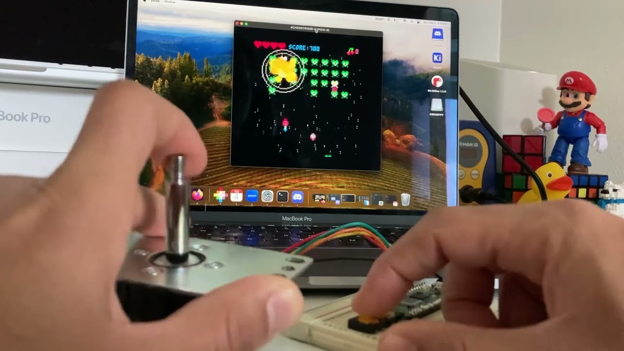 near storm
I’m thinking about writing a series of project guides called “look ma, no microcontroller!” on Adafruit Playground. The idea is to show the kinds of electronics projects you can do even without a processor. Like, dimming LEDs, RGB LEDs, variable power supply. Would this be of interest to you? 👍,🤷♂️, or 🥱
vagrant torrent
near storm
I’m thinking about writing a series of project guides called “look ma, no microc...
What qualifies as a microcontroller? I suppose ASIC chips don't count? Is a 555 a microcontroller?
ocean osprey
It might be interesting to some people but frankly idk if its something i personally would bother with, chances are if im making a project and i can just throw a microcontroller at it that is what im going to do
ocean osprey
THOUGH admittedly i have considered learning more regular analog electronics
near storm
vagrant torrent
What qualifies as a microcontroller? I suppose ASIC chips don't count? Is a 555 ...
Yes, that is the question. I was planning to focus on anything that doesn’t execute traditional assembly instructions. So, 555 are valid, EEPROM finite state machines, op-amps for stable control, etc
lucid bloom
I had some issues with my soldering but I managed to get it all happy and working through some trial and error. I can get the drone to arm and the motors work/spin properly so I am getting rather close to flying it. It took longer than expected, I stopped worrying about getting it wrong and focused on just getting it done with the least number of mishaps. I sliced a power wire, screwed up the GPS soldering, mashed a pin on the vtx, none of which were fatal errors.
 dawn coral
Made this guy for the kids. Modified it with a DFPlayer and tilt switch. Needed to use an npn transistor to trigger the dio play pin (was too lazy to look up any open uarts on the tiny project MCU). Video with the audio on a timer, selection to use debounced tilt switch instead (each kid wanted a different setup) - https://learn.adafruit.com/terrako/overview
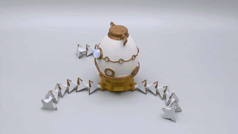
Adafruit Learning System
Build a shoulder-mounted companion robot
north mural
lucid bloom
I had some issues with my soldering but I managed to get it all happy and workin...
Always a good feeling when you get something working. Is that a ublox GPS module below the antenna? How well does the video feed work? The little FPV camera I got for my RC car is kinda bad and full of static but it was only like $40. It's hard to find a good FPV camera setup without spending hundreds on something DJI related.
north mural
dawn coral
Made this guy for the kids. Modified it with a DFPlayer and tilt switch. Needed ...
Those are adorable. I don't play Zelda so I don't get the reference. They remind me a cute mashup of R2D2 and a Dalek with tentacles. 🙂
lucid bloom
north mural
Always a good feeling when you get something working. Is that a ublox GPS modul...
Yes that is ublox GPS, the video seems to work ok except I haven't range tested it. I took it apart too many times and now the mashed pin on the vtx is a missing pin so I ordered another one. I tried to keep costs down otherwise I would have gone digital. The GPS doesn't seem to like being next to the xt60 so I modified the nose design to have a surface to mount the gps to.
dawn coral
north mural
Those are adorable. I don't play Zelda so I don't get the reference. They remin...
Pretty much lol I do have a few gripes with the overall CAD design though. The major problem is that the bottom plate where it holds on the legs blocks a USB cable from fitting into the charger port, I could not plug in a cable to charge it without popping the base off the bottom which is not a good solution long-term. Retention for the legs is pretty poor as well, they fall off very easily. The servo horn mounting plate could very easily have been made significantly more sturdy, probably the weakest point of the build.
I'll have to see if I can get the step files from the design and make some adjustments, at least the base plate is easy to change
I might just run a drill bit through each of the legs and put a string all the way through to hold them on
north mural
dawn coral
Pretty much lol I do have a few gripes with the overall CAD design though. The m...
The easiest way to make a hole or enlarge a port is with a soldering iron. As long as you have a sponge and brass tip cleaner you can clean the tip after using it to melt plastic.
dawn coral
north mural
The easiest way to make a hole or enlarge a port is with a soldering iron. As l...
I have a Bridgeport..... Lol
And a drill press
There's no hole currently, it's a snap in ball retainer but it's too loose and comes out
The walls are too thick for a decent amount of flex too, so from a design standpoint it's either not going to fit or will easily fall out... Needs a secondary retainer... Considered a slip ring retainer but it wouldn't look good
lean elbow
Shoutout to @north mural for the suggestion to use mirror tint film to better hide the unlit segments of a seven segment display. It looks better in person but even photographed it's a lot more readable!
 dawn coral
I would love to modify the original CAD, but the edit design link on the Ada fruit project page is dead
 glad roost
dawn coral
I would love to modify the original CAD, but the edit design link on the Ada fru...
glad roost
dawn coral
I would love to modify the original CAD, but the edit design link on the Ada fru...
could you point to the page with the dead link?
dawn coral

Adafruit Learning System
Build a shoulder-mounted companion robot
dawn coral
glad roost
could you point to the page with the dead link?
this one, the edit design goes to a dead f360 project
glad roost
dawn coral
this one, the edit design goes to a dead f360 project
Oh, that's too bad. I'll tell the authors.
dawn coral
If they have it somewhere it'd be great to get back up
And if they want info on how I did the audio, I can pass it along too
 wicked horizon
hi folks we updated the link for terrako: https://a360.co/3w56fLD
we had to update our part directories and lot of project share links changed 🤦♂️
Share 2D and 3D design files and project files with anyone.
dawn coral
Woohoo!!
glad roost
@dawn coral 👆
dawn coral
@wicked horizon thanks, see the notes above on the changes I'd like to look at making?
dawn coral
dawn coral
Pretty much lol I do have a few gripes with the overall CAD design though. The m...
This
wicked horizon
dawn coral
<@330443644366618625> thanks, see the notes above on the changes I'd like to loo...
ah yea it was designed to fit the one we have here
 dawn coral
I went through 5 cords to find one I could cram in there lol
All of em caught on the leg retainer
wicked horizon
ah yea you can totally measure to fit the cable you have the most of
dawn coral
I'll probably pull the base out too, give some more wire room, flat bottom for printability
Kids love it
north mural
lean elbow
Shoutout to <@126221640559362048> for the suggestion to use mirror tint film to ...
You could cut 2 pieces to add more diffusion. Looks great though. Much more readable without the unlit segments being more pronounced.
lean elbow
@north mural I think that's an artifact of photographing it, IRL I can't see the segments 😄
north mural
Yup, took a couple pictures before I figured out how to capture the mirror reflectivity just right. Using the cutting mat with the grid reflected made the effect more obvious.
lean elbow
I just find photographing LEDs in general pretty difficult, at least with the only camera I have available to me on my phone lol
dawn coral
Do you want the info on the audio I added btw? Not sure if you want to include non Ada fruit parts, or redo it around the audio boards on the site
Didn't see a standalone MP3 board, just wav/ogg with onboard flash which isn't bad but much larger than what I used (DFPlayer mini)
https://a.co/d/fHjhf7X this, a microSD card and a 2904 transistor

HiLetgo 2pcs mp3 Player Mini MP3 Player Audio Voice Module TF Card U Disk Board for DFPlayer Audio Voice Music Module
north mural
Since it uses an Adafruit ItsyBitsy as the main board and most of the products are Adafruit it's ok to include links to other manufacturers parts. Attempting to substitute an Adafruit part that you don't actually use in the guide would be a bad idea as you can't ensure any included schematics will work without testing. There's plenty of precedence for this is many other Adafruit learn guides.
dawn coral
Yeah, I just added to it, only sub I made was the rgb neo pixel ring was out of stuck so I got rgbw lol
north mural
If you want to attempt to amend the Learn Guide to use an Adafruit MP3 player you could purchase and try testing it with one of the wave shield MP3 boards. https://www.adafruit.com/search?q=mp3
dawn coral
I looked a while back, and they were massive in comparison
north mural
That's not always possible since the Arduino Uno format is much larger than an ItsyBitsy and might not fit into the enclosure.
yep
dawn coral
I don't recall anything I could physically fit
Even the featherwing is exponentially bigger
north mural
A feather or featherwing would be the smallest as an adafruit part. Otherwise you would end up having to go elsewhere and that's ok.
If a part doesn't exist for the size you need then there's no way to keep it all Adafruit parts. So Adafruit might want to think about creating it so in the future your guide and others could use an all Adafruit lineup of parts.
You could shoot them an email they do take product/stocking suggestions.
dawn coral
Easy enough just not sure how much interest there might be lol
north mural
You might be surprised. There are plenty of people who actually prefer the ItsyBitsy form factor.
dawn coral
Yeah... Usually not messing with stuff that small lol this is actually the first non work related thing I've built in a long time lol I always forget how much of this stuff "regular" people use 🤣
I'll just keep my 208 pin MCU project over there .... Lol
north mural
@lean elbow I'm working on a 7 segment PCB that uses Adafruit backpacks to plug right into the board.

Pin header breakouts for externally mounted tactile buttons on an enclosure. Will replace the cardboard cutout I'm currently using. https://github.com/DJDevon3/My_Circuit_Python_Projects/tree/main/Boards/espressif/Adafruit Feather ESP32-S2/7-segment Multiplexed Social
lean elbow
DeLorean time circuit display vibes
north mural
Featherwing adapter PCB's came in today. Fit like a glove first attempt.

 north mural


One thing I learned during the chip shortage is not to rely on one distributor... and that even applies to Adafruit. The TFT Featherwing is my favorite display for circuit python displayio projects but they were out of stock for more than a year. So I set out to find a comparable display and made my own. This increases my options if I need another 480x320 SPI TFT in the future. It's not as slim as a TFT Featherwing but otherwise can act as a good replacement.
lean elbow
The Ruiz brothers highlighted my version of the rotary fidget toy project today on 3D Hangouts and I realized that I never shared any of the technical details for it or any of the updates I made after the initial post. I was able to remove the Propmaker Featherwing completely and just use the naked Feather boards, and I wrote custom Arduino code for the project. I'm going to spend some time in the next few days working on making a CircuitPython version to share (and a subsequent playground post) that should be easily adaptable to the Ruiz brothers' build, but in the meantime I thought I'd share the prints for it (and some inscrutable text/instructions in there about how you can choose to use a Feather RP2040 or an ESP32-S2/S3 and some other rambling 😂) https://www.printables.com/model/733974-ano-led-fidget-toy

Printables.com
3D files for a rotary fidget toy designed for Adafruit Feather microcontrollers. | Download free 3D printable STL models
I'm going to attempt to parlay the obvious Simon inspiration into a version of the game as well
 void spoke


Made this camera then modified the case I found on thingivirse to fit a battery and a charging board to make it fully mobile. It is streaming its camera feed with libcamera over tcp to osb
Edit: I have switched to having the pizero2 run an rtsp server. This allows much better connection to OBS.
dense swan
https://www.youtube.com/watch?v=kcKTfaWmDh8&lc=Ugz9nuz_NR0oVbJyf8t4AaABAg&ab_channel=Rotoforge
we turned a ceramic glow plug into a open source 1300 C hotend for printing metal and ceramic on the home desktop.
still needs a lot of testing and tuning, but we ay have test prints very soon.

A quick video of Sam and I clearing a molten bronze jam out of our new ceramic hotend for printing metals, plastics and ceramics.
https://www.printables.com/model/635347-beru-glow-plug-cgp-002
the glowplug we are using is characterized and modeled on my printables page.
this is part of a opensource project for printing metals and ceramics on ...
north mural
If you thought 300C was dangerous for home hobbyists wait until you see 1300C. 🔥 I'm amazed the hotend doesn't melt all the plastic parts around it like the fans and housing. This could be an interesting new method for homemade PCB's. I enjoyed the friction spindle idea too. Be safe you guys, the concepts you are working on are a bit dangerous but it seems as if you're taking a scientific approach to it. Wear safety goggles. I can imagine clearing a metal clog wouldn't be a trivial issue to deal with. For metal you're likely to require a much larger and longer hotend, heat creep will be an issue if you attempt to use a short hotend with metal that was designed for plastic filament. Tip my hat to you for exploring very interesting concepts.
 high imp
Testing new iot-thing board based on an ESP32 - designed in KiCad 7
https://youtu.be/Equ5EEIkyHM
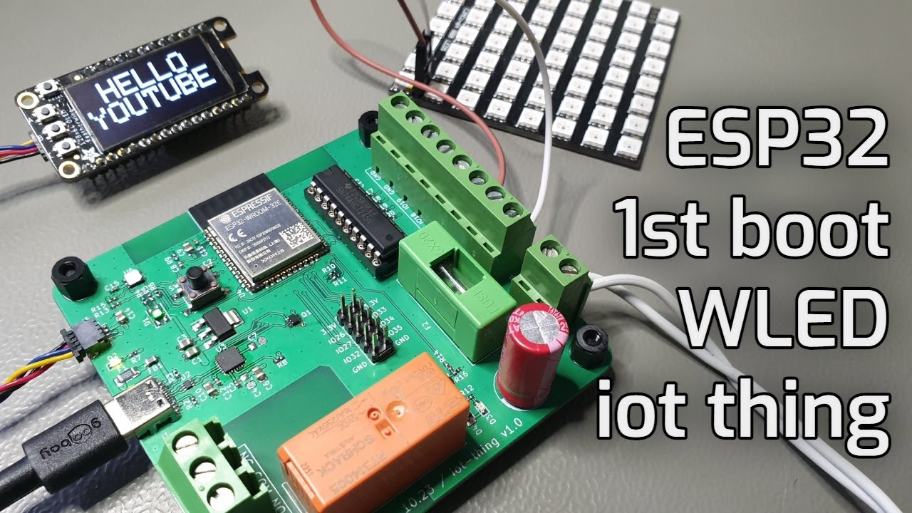
Complete step-by-step test process going through the different functions on the iot-thing board.
Arduino code and WLED are used to test the functionallity
▶ Subscribe: https://www.youtube.com/channel/UCqyPRKnXxjDJOQAXV__6yNw
Click the Bell Icon to get notifications about my future videos!
Link to Arduio code
https://github.com/mortens-lab/iot-...
lean elbow
lean elbow
The Ruiz brothers highlighted my version of the rotary fidget toy project today ...
Getting there...
spring pulsar
Awesome!!!
lean elbow
Thanks! I'm waiting on the Stemma QT version of the ANO breakout board to arrive to make sure the code works with it as well (I only had non-Stemma ones on hand), should have the code up in a few days 😄
Also...now I really need to add sound to this thing lol
spring pulsar
I wrote it for a NeoTrellis RGB, where you could press any of the 4 buttons in a corner. I then also had uncommon layouts (4 vertical lines, and all 16 buttons). I never made a case for it, but maybe someday...
lean elbow
oh that's awesome! I have a NeoTrellis M4 that's been collecting dust for like 2 years, one day I'll figure out something cool to do with it 🤔 It does seem like a great platform for simple LED games
spring pulsar
Oh it's an awesome platform. Although, I really wish it was 5x5...
 hoary compass
I turned my 8x8 neotrellis into an electronic chess board. Still need to figure out how to program beyond "cut color > paste color" but you can play most of a chess game. No pawn upgrading yet lol, need to figure out how to program long presses to do what I want without affecting the short presses.
 lean elbow
That's a rad idea!
hoary compass
Thank you! I had to prompt chatgpt for the code to get this far since I know very little programming.
Also soldering the 8x8 neotrellis together was very daunting so I'm proud I managed that much xD
 normal orchid
On each press note the time. Perform actions on button release, or on the time threshold of the start of a long press. I'd make a button state list to track the held buttons, or all of them, then you can debounce if desired.
sand grotto
Two Plaground guides I've cranked out this weekend that others may find useful:
- Circup support for web workflow: https://adafruit-playground.com/u/tyeth/pages/using-circup-with-web-workflow
- Using a QRcode to update settings.toml with wifi credentials and auto-connect, with shutter button read/readWrite toggle at boot: https://adafruit-playground.com/u/tyeth/pages/memento-flicking-usb-readonly-write-boot-setting-wifi-using-qrcode [has some broken embeds and images i want to add but fine otherwise]
spring pulsar
Oh that QR code one is pretty cool! I had a similar thought using the Tiny Code Reader from Useful Sensors. I'm also working on a library to save things to NVM when it can't write to the flash drive (and them move it when it can...)
stark latch
This is a re-design of something I made several years ago. Much easier with a decent 3D printer.
https://www.youtube.com/watch?v=C1qa_cnrQKU

A new design of a project I made several years ago. Just a silly visual pun. Everything's 3D-printed except the music box, which came from Music Box Attic.
The STL files for printing can be found here: https://www.printables.com/model/761692-a-clockwork-a-clockwork-orange-orange
elfin sedge
I had to tweak colors for visibility more than aesthetics in a large, bright building. But here’s the scoreboard in service at the RC track. I’ll get more pics and videos next time we’ve got a good crowd for racing.
 north mural
That is awesome!
lean elbow
Just published a playground write-up on some CircuitPython firmware I wrote for the ANO fidget toy I built a couple of weeks ago https://adafruit-playground.com/u/squid_jpg/pages/custom-ano-fidget-firmware
If you've built (or are planning to build) the Ruiz Brothers' fidget from the Adafruit learn guide (https://learn.adafruit.com/neopixel-rotary-fidget/overview), this firmware works with that as well!
north mural
lean elbow
If you've built (or are planning to build) the Ruiz Brothers' fidget from the Ad...
Can tell you put a lot of work into the helper libraries. Well done.
lean elbow
@north mural Thanks! 😄
north mural
Just pulled the trigger on 2 PCB designs. ST7796S Featherwing & ST7796S QT Py BFF. Since learning about SPI bus sharing was able to fit a built-in SD Card, TFT, and TFT touch controller using only 7 pins. Since it used such few pins that lead me to try to make it work with a QT Py and was able to fit it and have 4 spare pins left.


 hexed star
In case its helpful for anyone, I've made a template repo for embedded development in rust https://github.com/kkingsbe/STM32-Rust-Quickstart

GitHub
Contribute to kkingsbe/STM32-Rust-Quickstart development by creating an account on GitHub.
glad roost
elfin sedge
I had to tweak colors for visibility more than aesthetics in a large, bright bui...
I showed off a closeup of your panel from the photo in an internal meeting. This would be a great project to write up for https://adafruit-playground.com/ if you would like to document it somewhere, or just show it off with the specs.
elfin sedge
glad roost
I showed off a closeup of your panel from the photo in an internal meeting. This...
Oh cool, thanks for sharing! I’ll check it out, I’d like to help or inspire others to do similar projects. And thanks again for the quick fix a few weeks ago, it was nice being unblocked so quickly. 🙂
glad roost
it's nice to be able to fix a bug quickly 🙂
you could also go on Show & Tell on Wednesdays 7:30 Eastern time, but a write-up is for posterity and is searchable!
elfin sedge
glad roost
you could also go on Show & Tell on Wednesdays 7:30 Eastern time, but a write-up...
I could probably do both. Would they be able to show a video of it while I talked about it? It’s at the track now and is more interesting with live data.
glad roost
elfin sedge
I could probably do both. Would they be able to show a video of it while I talke...
you can share your screen when you're on the show, so you could show a video locally. Usually the slots are 2 minutes each, but it depends on how many people show up
elfin sedge
glad roost
you can share your screen when you're on the show, so you could show a video loc...
Sounds good. I’ll get some video next time I’m out there.
north mural
Circuit Python XPT2046 touch driver calibration example. Got pressure calibration working too Min,Max Values for X:(105,1984) Y:(114,1988) Z:(313,1611) https://github.com/DJDevon3/CircuitPython_XPT2046
exotic sierra
I’ve written a simple 16b pipelined CPU. The LEDs flashing indicate the stage of pipeline it’s in.
i've put the source up here: https://github.com/skerr92/ice5lp4k_examples/tree/aes-encryption/pipeline_cpu

GitHub
Examples for iCE5LP4K FPGA: BRAM, SPI, flash, DSP, and other basic examples - skerr92/ice5lp4k_examples
solemn vector
Complete prototype of an Arcade controller for the fantasy console PICO-8 using CircuitPython and the HID library: https://github.com/isacben/picocade

GitHub
An arcade controller for the pico-8 fantasy console. - isacben/picocade
lean elbow
eternal maple
Working on sample waveform and envelope visualization for CircuitPython synthio. Here's a test of the WaveViz class on the tiny OLED display of @terse totem 's Faderwave synth: https://www.youtube.com/watch?v=-GUvC4f2p-o. The synth's faders are used for the six additive oscillators and five envelope parameter values. The WaveViz library is available in the CircuitPythonCommunityBundle. Repo: https://github.com/CedarGroveStudios/CircuitPython_WaveViz
Playground note: https://adafruit-playground.com/u/CGrover/pages/waveviz-plot-a-synthio-wave-table-or-envelope
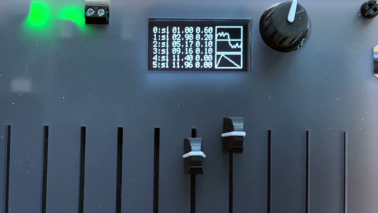
A proof-of-concept test for incorporating an ADSR envelope plot as an option for the CircuitPython WaveViz helper library. Testing was performed using John Park's Faderwave Synthesizer device (https://learn.adafruit.com/faderwave-synthesizer) and the WaveBuilder additive synthesis library. The last five faders were used to set the envelope param...
GitHub
A CircuitPython class to create a positionable displayio.TileGrid object from a synthio.waveform wave table or synthio.Envelope object. - CedarGroveStudios/CircuitPython_WaveViz
north mural
It’s like 5mm pitch matrix panels had a baby. 2.5mm panels are adorably small and still have the same amount of pixels. Will be working on designing 3D printed brackets since it seems many people liked my 5mm bracket designs.
 spring pulsar
north mural
It’s like 5mm pitch matrix panels had a baby. 2.5mm panels are adorably small an...
spring pulsar
north mural
It’s like 5mm pitch matrix panels had a baby. 2.5mm panels are adorably small an...
I just thought you had really big hands...
north mural
5mm vs 2.5mm

Photoshopping hands to make the panels appear bigger or smaller is something a marketing dept would do. This is a real size comparison.
I figured if I'm going to continue to add to my 5mm matrix I'm either going to need a much bigger wall, or completely switch to 2.5mm.
 feral marsh
Finally got my new alarm clock built. TL;DR 3.5 inch TFT, ESP32-S2 Feather, Music Maker Featherwing, and you can just see the VEML 7700 breakout peeking above the top left corner of the TFT. All put together on a 3d printed base. Follow the thread for more details, since there's a lot to report. 🙂
 trim ore
I forgot to post this earlier, but a big thanks to everyone here who helped me with figuring out the hardware for my flower!
its thumbwheel controls the modes, so it has solid white at one end of the pot, a manual solid color hue sweep as the thumbwheel is turned, and then this shifting rainbow at the other end. unfortunately the vid of all of that is too big for me to post.
and huge thanks to my wife for coding everything ^^
 carmine lagoon
Hello here, making nice progress on my open-source pocket groovebox: https://youtu.be/GBRBZO4gkvU
I thought I'd show it here since the watching the AdaFruit community helped me a lot in my hardware design journey 🤗
 carmine lagoon
May I ask what people here think about the name "Wee Noise Makers"?
north mural
carmine lagoon
May I ask what people here think about the name "Wee Noise Makers"?
With the video as context nothing wrong with the name. Without context especially in the U.K. it might be confused for something else. 😅
sand grotto
carmine lagoon
May I ask what people here think about the name "Wee Noise Makers"?
Wee up north (uk) means small, a Wee baby, which is nice and endearing. Also evokes thoughts of fun sounds made with voice. Not sure if other connotations would put some off.
carmine lagoon
Thanks 👍
pallid saffron
sometimes in the US, "wee" is used as a euphemism for urination, especially for small children (my parents were teachers so i skipped straight to "bathroom")
sand grotto
here too 🟡
north mural
With that said no one really made of fun of the Nintendo Wii for the name in that regard even though they sound the same.
sand grotto
definitely a few giggles here, but mostly overshadowed by people hurling the wii nunchuck through the tv playing tennis (not using wrist strap)
north mural
I mean you could probably name a device 💩 and kids would love that because it would make their parents eyes roll.
crystal pier
 burnt wyvern
Honestly im surprised the name Wii didn't even phase me as funny as a kid, knowing my immatureness then I probably would've been all over it.
crystal pier
When I initially saw it, I read it as double-u-i-i
Also, 4 year olds are the undisputed heavyweight boxing champs in wii sports.
My cousin beat me sorely.
(Well, daughter of my cousin)
burnt wyvern
It's basically a contest of "how fast can you move your arms back and forth without accidentally hitting yourself" 😆
 thin turret
I made a very silly module that "models" a trumpet. The knob selects the partial (C,G,C,E,etc) and the switches up top are "valves" and the switch to the left is the trigger

 gusty shard
(Time and) Temperature
 gusty shard
 queen veldt
I built a 3D printed 6-axis robotic arm using the Feather M0 and Feather M4 and RFM69 feather wings. The project is on Printables for anyone interested in building it themselves. The Printables page includes a Reddit link to see it running as well as the code, and assembly manual. Printables link: https://www.printables.com/model/742414-6-axis-robotic-arm


Printables.com
I designed and built this 6-Axis Robotic Arm from the ground up. PDF assembly manual included. | Download free 3D printable STL models
 cosmic mulch
Props for two things: 1. The robotic arm and 2. Your username based on one of my favorite movies.
queen veldt
cosmic mulch
Props for two things: 1. The robotic arm and 2. Your username based on one of my...
Hahaha thank you!
cosmic mulch
Twist it upside down and you can mimic the chair that Lawrence Fishburne sat in. 😆
queen veldt
cosmic mulch
Twist it upside down and you can mimic the chair that Lawrence Fishburne sat in....
Lol I see it! I'll have to beef it up a bit for that
cosmic mulch
How long did it take you to build it (after printing out the parts) ?
I'm intrigued by this, but want to know how much time I would possibly have to set aside to build it myself.
queen veldt
With or without procrastination? Lol I worked on this project for a little over 2 years, a mix between having to do a major redesign, as well as me moving slowed me down quite a bit. The total print time though it probably under a week if you print continuously
cosmic mulch
Sorry, I meant 'build' as in 'assembling' it.
queen veldt
I'd say it could take 2-3 weeks depending on how much time you have available to you
cosmic mulch
Well, that tells me it's definitely not a simple "slap together with spit and chewing gum" project, but a proper one. I like that.
queen veldt
It's mostly print time, wiring, and the heated inserts that take the most time
Depending on skill level it might be quicker for you. I'm a noob with electronics and soldering and stuff
cosmic mulch
It's an awesome looking robotic arm, and I'm also half-tempted to build a GLaDOS head for it, too. 😆
queen veldt
It's hard for me to gauge right, cus it took me a lot learning the gearing, and troubleshooting all the code and stuff. But all of that is done now, so it should be much faster. Just hard for me to estimate
cosmic mulch
queen veldt
Depending on skill level it might be quicker for you. I'm a noob with electronic...
That thing does not scream "noob with electronics and soldering". It screams professionalism, with good attention to detail.
queen veldt
cosmic mulch
That thing does not scream "noob with electronics and soldering". It screams pro...
Thank you, I tried really hard so I appreciate the kind words!
cosmic mulch
Any particular type of filament you used for the plastic in your 3D printer? Like, one being stronger over another?
I'm not sure how heavy those motors are, and if any strain could be put on everything else if one filament is better than another.
queen veldt
Most of the arm is PETG, the ring and sun gears are PA6-CF, and the planet gears are PC Blend
I was mostly concerned with the strength of the gearing, and even then my choices may be overkill. PETG is definitely strong enough for the rest though
cosmic mulch
I think overkill is better, because you never know if you might do upgrades to it later on and it'll require that kind of strength.
queen veldt
Exactly, that's a good point
cosmic mulch
Regarding your soldering, did you use any of these to help simplify the process?
https://www.amazon.com/Connectors-Sopoby-Waterproof-Electrical-Automotive/dp/B0BKSJQC9Q

400PCS Solder Seal Wire Connectors, Sopoby Self Soldering Heat Shrink Butt Connector Solder Sleeve Waterproof Insulated Electrical Butt Splice Wire Terminals for Marine Automotive Boat Truck
queen veldt
Funny, I just used those the other day for the first time. They work great! I didn't get to use them on this project though
cosmic mulch
They're my go-to in my electrical toolbox when I have to do wiring on my cars.
queen veldt
I'll have to grab some, I gotta bump my connector stash up
cosmic mulch
Not sure what you use for soldering and heat gun usage, but I recommend these if you need something portable:
https://www.amazon.com/Dremel-2000-01-Precision-Butane-Soldering/dp/B00MJW08JK

Fire up your creativity. Our state-of-the-art butane tools are your sure-fire solution for cranking up the heat on all your projects. Fancy a bit of welding, soldering, melting, shrinking or paint removing? No worries – you can do it all with your Dremel Butane Tool. These unique tools are the ho...

Fire up your creativity. Our state-of-the-art butane tools are your sure-fire solution for cranking up the heat on all your projects. Fancy a bit of welding, soldering, melting, shrinking or paint removing? No worries – you can do it all with your Dremel Butane Tool. These unique tools are the ho...
queen veldt
I didn't know Dremel made torches, that's sick haha
cosmic mulch
Mainly what I use with those butt connectors, is why I mentioned them. Because of their smaller size, the torch's curve attachment is well suited for them; versus my heat gun which has a much wider nozzle, and can risk heating up more of the wire insulation than I want.
The Dremel soldering gun is my favorite for when I have to get into tight spaces, or areas where a long extension cord would be a pain.
queen veldt
Yeah I was using a normal heat gun and the results varied. I think the tighter heat concentration of the torch would give better results
cosmic mulch
It has, in my experience. When I used a normal heat gun, I risked melting or over-heating the solder inside the connectors.
queen veldt
I'll keep that dremel in mind, thanks for the tip!
cosmic mulch
Not a problem, happy to help!
 analog nymph
I have a Hantek 6022 PC connected scope and I did a mod I found on the Internet to add AC coupling to the scope. I chose to do a surface mount homemade PCB for the mod. Here’s a picture and a screenshot of a 40 kHz, 10 mV sine wave with a 5V DC offset being captured in AC coupled mode.


 wide star
I made this LED focused development board called the LED Mango. The key innovation is that you can solder addressable LED strips directly onto the LED Mango! No more torn wires and messy projects. The LED Mango features an ESP32-C3-MINI, Stemma QT for sensors, and GPIO pin headers. It's designed for 5V addressable LED strips like Dotstar, Neopixel, APA102, WS2812, WS2812B, and more. It comes with WiFI + Bluetooth, and it's matter-compatible. Perfect for home automation + a wide variety of other projects. It has a USB-C port and a barrel jack to make powering your projects easy. I would appreciate feedback from the community here! Thanks! It's also be happy to share this on the Adafruit show and tell.


 wide star
 feral orchid
Chua's circuit on a breadboard
 lean elbow
Helldivers II stratagem macros 😅
 thin turret
Not having a scope I found myself jamming LEDs into a USB centronics device and swinging it around so I could use persistence of vision to see the data moving through it. Genius or madness over a $9 device with poor reviews on Amazon?
dense swan
https://www.youtube.com/watch?v=9DkNUEkR0hs&ab_channel=Rotoforge
I documented my process for making 1300 C hotends for the ender 3 out of ceramic glowplugs.

This is part of an ongoing open source project for printing metals, and ceramics on the home desktop at low cost.
We have a discord channel where others contribute to the project here:
https://discord.gg/Hdz8JkdSHP
We have a github here:
https://github.com/Sindry-Manufacturing/rotoforge
It is in desperate need of update and will be updated soo...
crystal pier
dense swan
https://www.youtube.com/watch?v=9DkNUEkR0hs&ab_channel=Rotoforge
I documented my...
Nice, though I feel like you should have added horns to the thumbnail 😈
dense swan
crystal pier
Nice, though I feel like you should have added horns to the thumbnail 😈
lol
thanks...I am trying not to lean into the insanity bent too much.
I am already on edge dreaming about glowplugs every night...
dense swan
we have a discord if its ok to post it here
for anyone who wants to keep tabs/heckle/contribute
 ruby ledge
I just released a new version of my AnimatedGIF library which adds new features and increases the speed of decoding. The 2 major new features are that I added a 'Turbo' mode which can greatly accelerate decoding speed in exchange for using more RAM. The second feature is "COOKED" pixel output which simplifies your code by doing the pixel merging and disposing for you.
https://youtu.be/s8Ks_uhR1qQ

Just updating your projects with the latest version will improve the decoding speed by 5-10% without making any changes to your code.
exotic sierra
ruby ledge
I just released a new version of my AnimatedGIF library which adds new features ...
Nice work! I might have to try this out sometime this weekend
 proven ruin
ruby ledge
I just released a new version of my AnimatedGIF library which adds new features ...
proven ruin
ruby ledge
I just released a new version of my AnimatedGIF library which adds new features ...
looks great; got a link?


 dire axle
Made a thing that shows any song I have currently playing on Spotify. Goes through a gallery of photos when nothing is playing.
 north mural
dire axle
Made a thing that shows any song I have currently playing on Spotify. Goes throu...
north mural
dire axle
Made a thing that shows any song I have currently playing on Spotify. Goes throu...
The LED shining through the black PLA is amazing. Didn't know you could do that. Very cool! Congratulations on a brilliant GUI too. It looks great!
dire axle
north mural
The LED shining through the black PLA is amazing. Didn't know you could do that....
Haha thanks, honestly just experimented till I got something that looked good 🙂
north mural
That's what it's all about. Well done.
lean elbow
Reminds me of the "breathing" LED on old macbooks. Very cool effect. Was it just a matter of using a really thin wall to make it show through like that?
dire axle
lean elbow
Reminds me of the "breathing" LED on old macbooks. Very cool effect. Was it just...
Yup more or less, I used Galaxy Black filament and made the wall 0.4mm, then I printed a diffuser in white filament which is another 0.4 mm so the individual neopixels wouldn’t show up
lean elbow
dire axle
Yup more or less, I used Galaxy Black filament and made the wall 0.4mm, then I p...
Awesome, thanks! Excited to try this.
dire axle
lean elbow
Awesome, thanks! Excited to try this.
🙂👍
sand grotto
proven ruin
looks great; got a link?
I assume it's this one of his libraries: https://github.com/bitbank2/AnimatedGIF Larry "Mr Optimize" Bank, aka @bitbank2 on github

GitHub
An optimized GIF decoder suitable for microcontrollers and PCs - bitbank2/AnimatedGIF
 grand jay
64x64 HUB75 matrix, driven with an Arduino Micro running a hacked up 32x32 plasma demo from the RGB matrix library. every other row is used, and pixels are doubled horizontally
exotic sierra
for anyone with an iCE40 fpga, here's the source on github: https://github.com/Oak-Development-Technologies/ice40_rgb_rainbow_chase

GitHub
RGB Rainbow Chase example for iCE40 FPGA using PWM - Oak-Development-Technologies/ice40_rgb_rainbow_chase
 sudden sail
My first real success with microcontrollers! I’m very proud of myself for getting this screen working.
 severe pine
The most complicated design I've done so far - a little ESP32/RP2040 development board with a built in OLED, RGB LED matrix, and SD card reader! Would love some feedback on the overall design and routing if possible 👀


The plan is to use this with the adafruit esp32spi library, modified to use different pins for SPI, if that'll work without a hitch like I'm hoping it will
grand jay
gradient colorbars on an Arduino Micro driving a 64x64 HUB75 matrix, 12-bit color, at full resolution
grand jay
gradient colorbars on an Arduino Micro
north mural
A PCB with 8 slim switches and pin headers. Intended to be mounted in enclosures for button uses.


 sonic fractal
severe pine
The most complicated design I've done so far - a little ESP32/RP2040 development...
sonic fractal
severe pine
The most complicated design I've done so far - a little ESP32/RP2040 development...
Oooooh that is goood
spring pulsar
Super excited. After some work, back and forth and time, NOAA updated their WMM page with my library (that I specifically wrote so it could be used in CircuitPython)
National Centers for Environmental Information (NCEI)
The World Magnetic Model (WMM) is the standard model for navigation, attitude, and heading referencing systems using the geomagnetic field. Additional WMM uses include civilian applications, including navigation and heading systems.
grand jay
animated rainbow effect on a 64x64 HUB75 panel, in 12-bit color, driven from an Arduino Micro. scan lines are calculated on the fly, with a bit-sliced flash lookup table for hue, and an 8-line FIFO
north mural
12-bit color. that blows the doors off what Circuit Python can do with Hub75 panels. circuit python does have much nicer displayio possibilities. for animations though, Arduino 👍
clever stone
I am learning CircuitPython and synthio. I have a simple WAV file drum kit working and (separately) I have this wavetable demo working. I hope to combine them but “baby steps” 😜
I started with PWM audio but I2S is so much better.
grand jay
huh, i think CircuitPython should handle 12-bit just fine? that’s a bit depth of 4, and the Learn guide suggests 6. i don’t have any ARM boards working with the panel yet: i need level shifters @north mural
north mural
grand jay
huh, i think CircuitPython should handle 12-bit just fine? that’s a bit depth of...
Oh I thought it meant a bit depth of 12. 😬 sorry! ok now i'd like to see how it performs on a bit-depth of 6.
 gleaming adder
lean elbow
Helldivers II stratagem macros 😅
gleaming adder
lean elbow
Helldivers II stratagem macros 😅
Hey Squid, I'm trying to reproduce your helldivers-2.py setup, and for somereason I'm not seeing it pop-up as a page on my macropad. What libs are on your pad?
lean elbow
gleaming adder
Hey Squid, I'm trying to reproduce your helldivers-2.py setup, and for somereaso...
That's odd 🤔 Unfortunately I'm traveling at the moment and don't have physical access to the macropad, but if I recall correctly I just used the project bundle from https://learn.adafruit.com/macropad-hotkeys/project-code and then added the helldivers-2.py source file to the /macros directory. Also since I'm only using the pad for helldivers I removed all of the other .py files from the /macros folder so that helldiveres-2.py was the only one in there, but tbh that shouldn't be necessary

Also I'm pretty sure I used CircuitPython 8, so I would have used the libs from that directory in the bundle
Ah I might have an idea what your problem is. I'm wondering if there's an error in my code that's causing it not to compile, and that's why it's not showing up
I bet the issue is this line:
START_INPUT = Keycode.CTRL
Should be:
START_INPUT = Keycode.CONTROL
I'll fix the code on my playground page. I actually have my own keyboard remapped to be more like MacOS so my control key is mapped to ALT (so in my personal code I actually use Keycode.ALT), which is why I didn't catch the silly error. Let me know if that fixes it for you please!
lean elbow
Sure thing! Glad that fixed it 😄
dark cairn
Made a module to easily make tty terminalio objects. It also supports injecting other console-compatible objects into it for input.
This way by making a keypad input-only console object and combining the two we have modular display controls.
And then since it's a console object it can be plugged into jcurses for terminal applications.
north mural
Pulls API data from RocketLaunch.live and displays it on a TFT. https://github.com/DJDevon3/My_Circuit_Python_Projects/tree/main/Boards/espressif/Unexpected Maker Feather S3/4.0 ST7796S/RocketLaunch_Live API Display
gleaming adder
lean elbow
Sure thing! Glad that fixed it 😄
i added all the stratagems in groups so you can just un-comment the ones you want, also left some blanks you can un-comment so you can keep your keys organized.
lean elbow
gleaming adder
i added all the stratagems in groups so you can just un-comment the ones you wan...
Oh rad, thanks!
sonic fractal
So here is my DX32A board finished, it looks neat and it accomplishes its goal of being a breadboard compatible S3 board, but im not satisfied with this unit in particular, its unstable and disconnects constantly, however... most importantly of all, it werks

Hot wheels delorean for scale
sonic fractal
also wifi do werk
north mural
There's a new DeLorean?!?! I had no idea. It looks gorgeous! Glad they kept the gull wing.
What's the issue with the disonnects? Looks like a module so shouldn't be any different from any other S3 module board. :/
sonic fractal
north mural
There's a new DeLorean?!?! I had no idea. It looks gorgeous! Glad they kept the...
yuh, the delorean alpha5, its an ev and they made a collab with hot wheels as a promotion, personally i like it however i think it could have been done better, i think the front should have had 4 headlights like the original instead of 2
sonic fractal
north mural
What's the issue with the disonnects? Looks like a module so shouldn't be any d...
honestly no idea but i noticed it happens with my other generic s3 board
with circuitpython, starting up it connects, disconnects, and then reconnects as a storage device
both boards do this, so it seems to be normal behabiour
unlike the generic one, the one i made takes a couple of seconds to be decetced
and sometimes if i move or touch the board it disconnects
which may be a thing with the usb cable/port
what surprised me is how much the S3 heats up, average running temperature is about 40C°
ill try arduino firmware instead to see if the disconnects keep happening
north mural
sounds like usb wake or a dodgy usb connection. yes the S3 can get quite hot. the QT Py ESP32-S3 in particular because it's on a smaller pcb. thermal design with the S3 is important.
sonic fractal
north mural
sounds like usb wake or a dodgy usb connection. yes the S3 can get quite hot. ...
ill look up usb wake, a dodgy usb connection is very possible since i feel like it worsened after using the hot plate to reflow a capacitor, and about the thermal design, why dont they add a heat transfer pad to the rf shield?? they could use it as a heatsink, wasted potential, maybe ill do it myself for a future design
unfortunately a heatsink wouldnt fit on a qt py
north mural
sure it will, you can get heatsinks as small as 6mmx6mm
i just got a pack of them for an "obviously not UL certified" board i purchased that gets to 76C. though i have a feeling it won't do the job experimenting with heatsink sizes is part of thermal design.
sonic fractal
i mean it will fit however you wont be able to use it on a breadboard since the soc goes on the bottom of the qtpy, thats what i meant
north mural
ah yeah and that would make your breadboard quite toasty too
sonic fractal
This will do 👌
 north mural
yeah honestly i was thinking of 3D printing an enclosure with a little active fan too. the problem is if the fan is powered by the board then it might just get hotter. 😛
north mural
heatsinks and fans, one of those weekends.
sonic fractal
north mural
yeah honestly i was thinking of 3D printing an enclosure with a little active fa...
ive thought of that, something like the M5STACK stamps but with an added heatsink

really dig their look
north mural
would be funny to see a QT Py Fan BFF that's just a tiny little fan to help cool the QT Py. 🙂
sonic fractal
north mural
would be funny to see a QT Py Fan BFF that's just a tiny little fan to help cool...
maybe ill make it, sounds funny
yeah its def possible i found some really small fans
cunning lava
thermal camera module plugged into my robot
 kind burrow
Proud of this from a newbie Raspberry PI 4 user. I had a working weather program running on ESP32S2, and copied over to the PI.
Got the proper libraries installed, then just a few changes to the code, and the wifi connection (urllib), pins set up for the EYESPI cable on Beret, and it works.
Product 5783 Beret.
Only issue I had was the bitmaps needed to be converted to something different to not get error messages on the PI in OnDiskBitmap load. Using PIL image.convert
Forgot to mention blinka is AWE-SOME!
 sonic fractal
kind burrow
Proud of this from a newbie Raspberry PI 4 user. I had a working weather program...
sonic fractal
kind burrow
Proud of this from a newbie Raspberry PI 4 user. I had a working weather program...
Quite a neat project, ive wanted to make a weather station for a while now
But please put the pi inside a case, and put some heatsinks on
kind burrow
Yes thanks. Gonna order things like that very soon. Only had it a couple weeks 😀
sudden sail
I designed and 3D printed this custom enclosure for my Raspberry Pi 4B desktop computer. The bottom compartment holds a 500 GB SSD routed to the USB ports on the back. 2mm of clearance around the sides of the board.


 finite valve

https://www.otvinta.com/download14.html So I printed all the parts to one of these, assembled it, but didn't think it needed the overkill and proprietary nature of a Pi with Windows IoT on it to drive it.. Wrote all new code in CircuitPython and running it from a ESP32c3 SuperMini.
sand grotto
 remote sigil
What do you think folks? Powered by wled running on an Adafruit Feather ESP32 V2
remote sigil
What do you think folks? Powered by wled running on an Adafruit Feather ESP32 V2
which plugin or setup have you used for the audio reactive element? (I noticed they've added something in the new pre-release)
exotic sierra
Working on the renderings for KeyBoy 😎

 north mural
Ground plane hatching looks cool.