
#show-and-tell
1 messages · Page 2 of 1
 drifting crater
Also this is the first time in a while since I've touched AVR - I forgot how fast it was to compile 😀 lmao
 hardy veldt
Heaps of progress done. Added a music select/restart feature, an input mode (so it lights up when we play the piano ourselves), randomized light placements that scales across the entire strand in steps of 8, and I finally have a neopixel strip to test on and it works flawlessly (though could be optimized further if it slows down at large scale). I already have a couple of strands and a scorpio, I just need to bring them all together.

 unreal oriole
Total noob, and I realize this is peanuts compared to other projects here, but I finally got sample code working on a Waveshare RP2040-LCD-0.96 board (RPi Pico clone with built-in ST7735S SPI display running CircuitPython.). This has taken many hours of figuring things out, but I finally made headway tonight thanks to user @fathom kiln mentioning that the Pico doesn't automatically include SPI pin assignments. I'm not sure I can use this for my intended project, but at least I know I can get this little board working now.

 peak marlin
For any railway modellers out there (HO/OO gauge) - I remixed a PIKO compatible container to have a Pico(W) inside it, so that you can have a Pico hidden in plain sight https://www.thingiverse.com/thing:5856346


Added internal space and cut-outs to the original to allow a Raspberry Pi Pico or Pico W to be slid into the container. Wires have to be soldered prior to the insertion and fed through to the hole in the rear.
Now you can hide the a Pico in plain sight on your layout.
designed to be part of the terrain although you could make it mobile if you are mad enough 😄
 exotic sierra
peak marlin
For any railway modellers out there (HO/OO gauge) - I remixed a PIKO compatible ...
exotic sierra
peak marlin
For any railway modellers out there (HO/OO gauge) - I remixed a PIKO compatible ...
Rechargeable music trains have arrived 😂
Nice work by the way. Hobby train sets are so cool. I wish I had the space for one
peak marlin
The container is sized nicely to fit a Pico inside. This is actually a test piece of work I produced, as I am working on some 28mm scatter terrain with "Pico Inside" as a commission from a tabletop gamer friend.
exotic sierra
Ah nice!
 wary atlas
peak marlin
For any railway modellers out there (HO/OO gauge) - I remixed a PIKO compatible ...
wary atlas
peak marlin
For any railway modellers out there (HO/OO gauge) - I remixed a PIKO compatible ...
A scaled down model of a standard FBI mobile processing center, used to coordinate all the bird drone intel collected
exotic sierra
I wish automated little bird drones were a thing for model rail systems
Turn your table on and they go around doing birb stuff and then return to base when they need charging or you turn off the set
wary atlas
That’d be so cool
exotic sierra
wary atlas
That’d be so cool
Until you come down and they’ve achieved sentience and built a massive crow robot and are attempting to break out of your basement window
wary atlas
That would be one heck of a murder
 feral orchid
Work has been proceeding to perfect the crudely conceived idea of a 31V tesla coil.
 wary atlas
I want to replicate this
feral orchid
Specs:
About 1000 turns of 32AWG magnet wire on a 3.5in OD (marked as 3in since PVC is sold by ID) PVC pipe. 8in long
3D printed endcaps and primary
Resonant freq: ~400kHz
Primary turns: 2x 1 turn primaries
YSPACE Labs Modular Halfbridge SSTC driver (similar to loneoceans/labcoatz schematic (as well as many other half bridge SSTCs)) with IRFP460s (but IRFP260s would likely be better)
uses 70mA average, but probably more than 4A peak
wary atlas
Wowzers
feral orchid
I have design files if anyone wants to build their own
wary atlas
I do :D
 fathom summit
ILI9341 connected to a Pi Pico running QMK(this will be part of my keyboard design) and connected to a custom program on the computer which queries Spotify's API to draw, over custom HID messages, currently playing song's image 🤓
- low resolution because API provides 3 sizes of images, so i went for the smallest (64px) and draw each pixel as a 2x2 rectangle to fill the 128px display

 lucid bloom
ChatGPT API + CAVA + Home Assistant + VT220 = Retro chatbot
It's about 40 lines of python it's a loop of prompting for input then sending a webhook with the response to home assistant that then does the tts, it runs cava while mpd is running and then exits and starts over. I have a few other versions I'm playing with but this is the most appealing one.
feral orchid
That's cool
wary atlas
Nice! Personally I’d go for an era-appropriate synthesized voice
feral orchid
acorn computer voice go brrr
wary atlas
Found someone made an emulator drop-in replacement for the synth chip from the Acorn, could probably grab the samples from that :0 https://m. youtube.com/watch?v=sUVLglsuEE8
 limber pendant
I made a StepMania controller!

#shorts
This video is to showcase a stepmania controller I made.
 rustic ember
HEY. This has been thousands of times but I designed myself a circuit for soldering iron controller. Wanted to share it. Different than many other implementations I added shunt resistor to measure power. Any input on the way I drew schematics or suggestions about build is apreciated. 🙌
 feral orchid
Nice. That schematic is so clean
Much better than my mess of a tesla coil interrupter lol

I'm probably going to give it a complete overhaul in kicad
rustic ember
feral orchid
Nice. That schematic is so clean
mostly because i have much fewer parts than you do ahahahh 😄 If I had that much parts I'd probably create more pages for each elements (like boxes in my drawing)
 wind linden
https://github.com/Bexin3/Speeduino/tree/0.0.6/examples/Osciloscope
Made a project that allows you to view the incoming wave on samd21 arduino at 350 ksps as well as to meassure frequency between 20hz - 100khz, and have settable gain.

GitHub
Make your SAMD21 Arduino functions faster. Contribute to Bexin3/Speeduino development by creating an account on GitHub.
 languid nebula
CircuitPython + Adafruit_shapes + Blinka_Displayio_Pygame + uplot(for Pygame)


 sturdy sierra
Circuit Playground BF, set to light up as a timer for a larp I'm going to.
 reef flax
Got myself a Galactic Unicorn from pimoroni. Great value for the price. Anyway. I did not want to have to upload new code each time I wanted to change what it was displaying. As it has a Pico W running the show. I added a UDP server and now render the frame on my PC and throw the pixels at it. Very easy to do. Update rate is very fast. I have attached a video, sorry for the poor quality. Looks a lot better in real life. Adafruit should stock these. They are fun. 🙂
wary atlas
Ohhh, that’s so cool!
 distant marten
reef flax
Got myself a Galactic Unicorn from pimoroni. Great value for the price. Anyway. ...
distant marten
reef flax
Got myself a Galactic Unicorn from pimoroni. Great value for the price. Anyway. ...
Oh, blasting UDP data at it is a clever idea!
 high imp
Made this Arduino code and ESP32 based YouTube Subscriber button
https://youtu.be/qf96raURVvs

Learn how to make your own advanced YouTube button packed with a lot of cool features, such as speaker driven by programmable I2S interface, light level detection, DC-DC converter, built-in ESP32 WROOM module and much more.
A big shoutout to:
Bitluni for the initial version:
https://www.youtube.com/watch?v=wvBFtz7Ioio
Brian...
 sour pond
So, I got a few.
Recently published this project that uses a QTPY RP2040 as its brain, and heavily uses the USB-C to 15v barrel connector to negotiate the PD to the controller from a battery bank. Full plans, board schematics, and bill of materials I published via creative commons so that anyone that wants to can make their own and improve upon it...
https://www.macpierce.com/the-camera-shy-hoodie
It's recently been picked up by a few news outlets as well -


Mac Pierce
A DIY wearable for avoiding recognition on IR security cameras.
In fact, I sourced the snaps used on the IR boards and the JST connectors from Adafruit...

 spiral scaffold
Oh shoot I saw this on twitter. Grats on the build!
sour pond
Thank you!
lucid bloom
I pitted the openai chatbot API against Eliza the 1960s Rogerian psychotherapist chatbot with python. It produces a rapid fire ai therapy session.
https://gist.github.com/matt-desmarais/72033fc275390c9ffc785b4bbd085a19

 stark lava
I made a fork on Raspberry Pi Pico/MicroPython 2FA TOTP Generator. Instead of a Pico Display Pack I used a 16x2 Character LCD and also made some changes on time synchronisation. https://github.com/kleo/pico-2fa-totp

GitHub
Raspberry Pi Pico/MicroPython 2FA TOTP Generator. Contribute to kleo/pico-2fa-totp development by creating an account on GitHub.
 stark latch
Made a custom embossing tool generator in OpenSCAD. Y'know, for embossing initials or logos on important documents and stuff. 😀 https://www.printables.com/model/412641-customizable-paper-embossing-tool
 distant marten
stark latch
Made a custom embossing tool generator in OpenSCAD. Y'know, for embossing initia...
distant marten
stark latch
Made a custom embossing tool generator in OpenSCAD. Y'know, for embossing initia...
OpenSCAD getting the ability to import SVGs is huge- really helps my workflow in stuff like this!
hardy veldt
My MIDI/Neopixel player works like a charm. Wasn't confident with splitting power wires for the strands so I perfed together a simple power delivery board. I soldered the right-angle pins the wrong way but fortunately there's enough clearance below to fit the ribbon cable. Also replaced the musicmaker wing with an adalogger since all I really need is the card reader. Only thing left is to lay it out on our piano.
 hardy veldt
Still a mess of wires and the colors might need to be tweaked a little but it's finally done! RP2040 Scorpio running dual-core; MIDI playback on core0 and setting neopixels on core1. Scalable and perfect for the holidays.
Basically, they're sharing one base array that core0 sets and core1 extrapolates from to cover the entire strand. There's a bit of randomness introduced during setup so that the pixels corresponding each note + black keys are spaced more organically. It also has a host of other features but the main one is pretty much done.
 devout verge
Cool, but strobe warning?
wary atlas
Yeah, it’s a bit flashy. It looks cool, but I feel like it might be more pleasant if there were a bit of a fade in/out
hardy veldt
Noted. I was worried about that and originally wanted to implement a fade, though that is much easier said than done, I discovered. I'm past the hard part at least so I can definitely start figuring that out.
hardy veldt
Bit of a happy problem since I wasn't sure if it's gonna start lagging behind once I started using strands (currently at 150) but turned out becoming way more responsive.

 distant marten
Whoa, are the leg structures made of FR4?

 cunning lava
distant marten
Whoa, are the leg structures made of FR4?
cunning lava
distant marten
Whoa, are the leg structures made of FR4?
yes
distant marten
cunning lava
yes
So cool!
cunning lava
wary atlas
https://tenor.com/view/i-need-it-robert-downey-jr-gif-15118751
sadly, I can't find more of those servos anymore
but you can build its bigger brother, fluffbug
wary atlas
I might build a giant one
cunning lava
big robots are difficult
wary atlas
Challenge 

 vagrant snow
I guess is it okay to share here
 wary atlas
exotic sierra
Two weeks later
wary atlas
exotic sierra
Two weeks later
More likely I’ll forget XD I think I said if do this before
 burnt prism
Using the power of neopixels and 3d printing, I was able to bring my favourite video game prop to life!


 haughty sphinx
Wired this up based on the circuit playground express + relay switch guide. Added a button and some custom code to make it power my work station 😁
 languid sinew
I made an Opus player (more modern codec than mp3). Doesn't do the C-level smooth audio API yet.
peak marlin
Put a Lolin S2 Mini in a 3D printed case along with a https://www.adafruit.com/product/1312
I present "DerBroader71s Mini Server"
CircuitPython on the go wherever I am

This is the easiest way possible to add small, bright RGB pixels to your project. We took the same technology from our Flora NeoPixels and made them breadboard friendly, with two rows of 3 x ...
 upbeat lotus
I had fun this past week: a friend of mine wanted to use my growmax board with an ESP32 MCU, but the board was designed for the RP2040. I discovered the banana-pi esp32s3 chip in a raspberry pi pico form factor and got it working watering my plants with my growmax board. I also setup the code to make it easier to support alternative pinout MCUs that fit that pico form factor in the future: https://github.com/opensensor/growmax/pull/2/files
The BPI ESP32S3 is not as easy to setup with micropython as the rp2040 is, but I figured out how to do it.
Partly because there is no button for the boot pins, so I have to hold a wire over these two pads when I plug it in, and the uf2 drag-and-drop is broken and leads to corruption, have to erase the device and flash it with the appropriate bin file using esptool
 burnt wyvern
My 3D printable Game Boy shell is now available! The STL files are free to download while the Fusion 360 project is currently $3, but the project files will also be free once this project is complete. Currently only the front part of the shell is compatible, but I'm working on the back half of the shell too.
https://github.com/guighub/DMG-01-Shell
https://ko-fi.com/guiguig

GitHub
A replica Game Boy shell made in Autodesk Fusion 360 - GitHub - guighub/DMG-01-Shell: A replica Game Boy shell made in Autodesk Fusion 360

Ko-fi
Become a supporter of guiguig today! ❤️ Ko-fi lets you support the creators you love with no fees on donations.
distant marten
burnt wyvern
My 3D printable Game Boy shell is now available! The STL files are free to downl...
That's really awesome!
burnt wyvern
Thank you!
 stiff coral
A mini madame Bwahstrella from Mario Rabbids! Using an Ada fruit soundboard and 3D printed parts. I modeled everything myself. The base was made in Tinkercad and the figure was made in blender. Huge thanks to everyone here for helping. I’ll post the finished version once it’s assembled

I plan to make an original machine too
The Trivia Demon


My idea for that is more complicated. Basically it involves a trivia arcade game and the talking figure
distant marten
stiff coral
A mini madame Bwahstrella from Mario Rabbids! Using an Ada fruit soundboard and ...
Love the modeling work!!!
stiff coral
Thank you!!
reef flax
I found some example code to make a video device in TinyUSB lib for the RP2040 in their SDK. Makes the RP2040 think it is a web camera. The example just displayed a test pattern. Some hacking later (included an RGB to YUY2 conversion) I got some more 'interesting' rendering working. I need to poke about a bit more but seems the RP2040 USB is not fast enough to make it useful. 160x120 @ 10FPS is the best I can get it to do. Any faster and drops frames. Here is a video I captured using my web camera software. I want to see if I can change the output format from YUY2 to RGB565.
stiff coral
It’s done!!
 fathom kiln
stiff coral
It’s done!!
fathom kiln
stiff coral
It’s done!!
How does the pull string work?
stiff coral
fathom kiln
How does the pull string work?
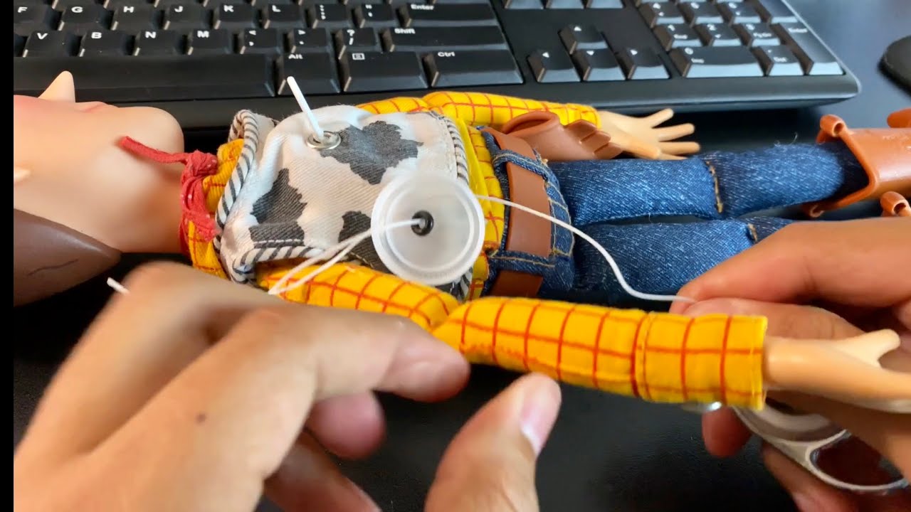
Movie Accurate Woody Video: https://www.youtube.com/watch?v=m1Y9GUHCDKI
Woody Custom Voice Box Files: https://www.instagram.com/strike_u/
Song from intro is of my band Heart Like War, listen here: https://youtu.be/YnYsJwEbT0w
TodayIGrewUP Patreon Link: https://www.patreon.com/join/TodayIGrewUP
Custom Mod Videos: https://www.youtube.com/watch?v...
like this 🙂
upbeat lotus
Got my button boards today.

 upbeat lotus
9x11 buttons per panel and 5 panels -- it was my first panelization but I let the board house manage that. Was definitely simpler than my last project but I wanted to not forget what I already learned and see how the panels come out. If anyone needs any buttons, hmu -- they fit the adafruit tactile buttons perfectly.
3-pin picoblade connector
distant marten
I'm trying to figure out a good punchline to "I got 99 buttons but ______ ain't one of them" but I can't get there
Also that looks awesome
burnt prism
finished my portal gun
neopixel's being the stars of the show
 distant marten
That looks amazing!
burnt prism
thanks, it's been the first thing i wanted to make since getting a 3d printer
 astral mason
Its truly beautiful. How long did it take you?
burnt prism
the printing took roughly 2 to 3 days and then all the electronics and assembly took a further 3
 north mural
Now you're playing with portals.
feral orchid
I tore down this VitalConnect VitalPatch ECG. Weirdly, the instructions tell you to discard the sensor, so I was able to tear it down since they don't want it back.


Does anyone know what some of these chips are? I identified the Macronix MX25U12832 128mbit flash and the Qualcomm CSR1012 bluetooth 4.1 LE SoC, but the main VCI1000-B0-1 (2217) microcontroller (probably) and some tiny ICs are still unknown.
There's an 8 pin IC labeled "116" that seems to have a power inductor on it. So I think it's a boost converter that provides 3.3v from the 1.5v button cells
An then there's a tiny 4 pin "AF" IC and a 209 (maybe 605) IC that might be an instrumentation amp or something. It looks kind of like an IMU.
distant marten
feral orchid
Does anyone know what some of these chips are? I identified the Macronix MX25U12...
The VCI1000 looks like it has a Broadcom logo on it
distant marten
Yeah, I don't know what the thing is
feral orchid
Prolly locked down
Might be able to hook up a serial to USB converter to those RX and TX pads. Might be able to get some debug terminal
upbeat lotus
What is it -- some kind of camera?
feral orchid
upbeat lotus
What is it -- some kind of camera?
Ecg (heart monitor) medical device thing with wireless capabilities
fathom summit
project starts to look like an actual keyboard :)

a good bunch of over-engineering here, just so i can expose many GPIOs and develop drivers for new hardware (and add other stuff to it in the future if i want to)
feral orchid
Almost finished designing the YSPACE Labs Hotplate. It'll be usbc PD powered, have intercangeable, standardized hotplates, and be powered by an RP2040 so you can drag and drop json reflow profiles into the emulated mass storage device
 exotic sierra
It’s the simple Blinky things in life
feral orchid
Board render
 fathom summit
project starts to look like an actual keyboard \:)
fathom summit
fathom summit
project starts to look like an actual keyboard \:)
almost done

 thorn walrus
I used a Magtag to make this sign for my partner's daily outdoor art display. It loads the information about the painting from a Google spreadsheet she can easily edit after changing out the painting. Viewers can press the "Like" button to play a little tune and increment the number of likes. Let me know if there's any interest in a more in-depth write-up. 2200mAh flat battery on the back lasts over a week on a charge.

 distant marten
thorn walrus
I used a Magtag to make this sign for my partner's daily outdoor art display. It...
distant marten
thorn walrus
I used a Magtag to make this sign for my partner's daily outdoor art display. It...
That's really cool!
devout verge
That's neat! Since the Magtag uses so little power, you could probably hook it up to a solar panel and not need to charge it at all.
wind linden
Finally got this library that speeds up the stm32h747 adc to releasable state, any feedback appreciated!!
GitHub
Speed up functions on your STM32H747 based Arduino - GitHub - Bexin3/STMSpeeduino: Speed up functions on your STM32H747 based Arduino
lucid bloom
The days where I have to type tweets on my wearable are no more. Piglassv2 + Whisper API + Twitter API = wearable with voice tweeting
https://twitter.com/_Matt_the_Maker/status/1634916118057058308?t=p5RIOoomu9PHVBxbXa1LWw&s=19

Does this really work from across the room?
This tweet was dictated to and uploaded from PiGlassv2
 Twitter
·
Twitter
·
 lean elbow
Built the sci-fi lantern from https://learn.adafruit.com/led-noodle-lantern
This was a really fun project! I really love the design of the case.
 distant marten
lean elbow
Built the sci-fi lantern from https://learn.adafruit.com/led-noodle-lantern
Thi...
distant marten
lean elbow
Built the sci-fi lantern from https://learn.adafruit.com/led-noodle-lantern
Thi...
Oh that's cool!
thorn walrus
devout verge
That's neat! Since the Magtag uses so little power, you could probably hook it u...
yeah I considered it and may still add a solar panel if I can get one free/used - I already had the rest of the stuff.
 timid vale
How many likes does it get every day? Could you put a hand crank generator on it and have it take a certain number of turns to register a like, and have the power also charge the battery?
timid vale
thorn walrus
yeah I considered it and may still add a solar panel if I can get one free/used ...
(sorry, forgot to send the last message as a reply)
thorn walrus
timid vale
How many likes does it get every day? Could you put a hand crank generator on it...
Ha! that's a fun idea. It gets anywhere from 5-20 likes per day mostly depending on the weather. In this case, I like that the Magtag is pretty slow to wake up from deep sleep and refresh the screen because it stops people (children mostly) from hammering on the button.
 noble yoke

SolenoidControl for Six Solenoids. PCB w/parts. Control with Arduino. No delays in code, only millis. You can adjust on and off times in code. No breadboarding. Ready to go. MOSFETS. 12 volt.
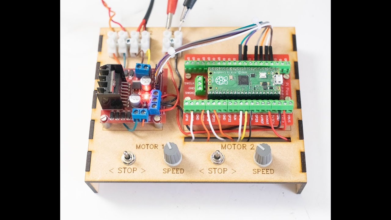
Motor Controller for 2 DC Motors using Raspberry Pi Pico with speed and direction control. For sale on Tindie. Assembled. Motors not included.
lucid bloom
I finally figured out a way to use voice commands with PiGlassv2 using OpenAI APIs. I'm using GPT as error checking for Whisper.
audio_file= open("command.wav", "rb")
transcript = openai.Audio.transcribe("whisper-1", audio_file)
command = (transcript["text"])
prompt = "The word(s) "+command+" is a match or phonetically sounds like which of the following, you must pick one: "+keysToString()```
```The word(s) Make your FARE Calm is a match or phonetically sounds like which of the following, you must pick one: Dictate Tweet, Picture Tweet, Kodi, RetroPie, Matrix, Camera, Record Video, YouTube Stream, Facebook Stream, Twitch Stream, ChatGPT, DALLE, Maker Faire Cam

GPT: Maker Faire Cam```
It costs roughly $0.0004 to run a command versed lava
lucid bloom
I finally figured out a way to use voice commands with PiGlassv2 using OpenAI AP...
versed lava
lucid bloom
I finally figured out a way to use voice commands with PiGlassv2 using OpenAI AP...
This is using the web api they just put out? aka .0006 a minute?
lucid bloom
Not sure exactly I think the new one is more expensive. Im using the gpt3 $0.002 / 1K tokens and whisper is $0.006 per minute
north mural
So many cool things this week.
 solid loom
Pegboard + DIN Rail + Push Rivets -- Over the years I have built up a collection of automotive plastic push rivets. When you need to attach two thin things together these rivets are fantastic. When I needed to get my DIN rail off my desk to make some room I grabbed a couple of small push rivets and attached the rail to my IKEA Skadis pegboard. It works a treat. The push rivets are available at any auto parts store. DIN rail can be had on Amazon and the electronic mounts are 3D printed from Thingiverse things. While I haven't tried this with regular round hole pegboard I am sure it will work with the right sized rivets.
 north mural
@solid loom There are many different styles of automotive push rivets though. Are you using the barbed style?
a link to a product might help others. apparently the ikea skadis is quite a popular pegboard
solid loom
north mural
<@708370662590513286> There are many different styles of automotive push rivets ...
To be clear, the push rivets that I am using for the Skadis pegboard are 5mm x 11mm because the hole size in the Skadis is 5mm. Either type rivet should work but mine are the kind with the center push post. When ordering just make sure that the shaft length is 5.5mm longer than the piece you are attaching to the Skadis. In this picture the plate for the Mega is 3mm thick, so the rivet would need to a shaft of 8.5mm.
 lean elbow
On that note, I recently built a bunch of Neopixel controllers using QT Py ESP32 Picos and running WLED, including two that I hooked up to Skadis boards
solid loom
lean elbow
On that note, I recently built a bunch of Neopixel controllers using QT Py ESP32...
That's a lot of RGB.
lean elbow
Yeah lol, most of the time I leave it on a more mundane mode, but it doesn't take as flashy of a video on "warm white" setting
I also built a WiFi remote to more easily control them

Anyway, these Skadis boards are awesome and very versatile!
 hallow imp
I'm slowly ratcheting up the size and complexity of my prints with the Elegoo Neptune 2S I bought a couple of weeks ago. A friend gave me a bunch of PETG for free, so I've been doing a lot of test prints with that material.
I thought this MacroPad Print-In-Place Stand was a good one to try. Biggest footprint I've done so far, and all the moveable bits work great.
 north mural
solid loom
To be clear, the push rivets that I am using for the Skadis pegboard are 5mm x 1...
north mural
solid loom
To be clear, the push rivets that I am using for the Skadis pegboard are 5mm x 1...
I honestly prefer that style. A forked nylon pry tool makes them easy to work with. Without the pry tool it's a fingernail nightmare trying to pop them up. 😛
 plush geode
thorn walrus
I used a Magtag to make this sign for my partner's daily outdoor art display. It...
plush geode
thorn walrus
I used a Magtag to make this sign for my partner's daily outdoor art display. It...
are you using the button to wake from deep sleep? If so, are you using ext0 or ext1? on another RTC pin? I can't seem to get the four MagTag buttons to wake the esp32 from deep sleep, hunting for examples where people have it working.
thorn walrus
plush geode
are you using the button to wake from deep sleep? If so, are you using ext0 or e...
yes, using a button (board.A1, wired to the JST plug on the board) to wake from deep sleep. there was a bug with wake_alarm for a long time - make sure you have latest circuitpython - https://github.com/adafruit/circuitpython/issues/5343
GitHub
CircuitPython version Adafruit CircuitPython 7.0.0-rc.1-62-gbe7d963a9-dirty on 2021-09-12; Adafruit MagTag with ESP32S2 Code/REPL import alarm import board import digitalio import neopixel import t...
solid loom
north mural
I honestly prefer that style. A forked nylon pry tool makes them easy to work w...
The ones I am using have a phillips head in them so you can "unscrew" them. Works about half the time. Bu I don't move things around much ......
 raven shale
After finding out that there's an API for my smart shades, I built a separate WiFi controller so that visitors don't need to use a phone for control. Had some issues with prototyping the concept on a RP2040/Airlift Feather combo but once moved to a picow it worked great!


 upbeat lotus
Had to order some stabilizers for the large cap keys, then I'll be able to finish it off and build another. Got it verifiably working though! Adafruit kee boar driver rp2040.

 ocean wave
I put together my first circuit and made a light blink.
 sand grotto
I got adafruit LvGL glue library working on the online simulator wokwi, allowing you to export a project from Squareline studio (WYSIWYG editor), and test your code works on loads of devices! It's arduino code for now, but wokwi supports circuitpython and micropython too.
https://wokwi.com/projects/359264266487565313
Only pico support currently (no picoW) and the franzino (wifi esp32s2) for circuitpython, because currently little interest shown (more micropython/arduino)


Run IoT and embedded projects in your browser: ESP32, Arduino, Pi Pico, and more. No installation required!
feral orchid
double-sided PCB hotplate that is under the JLCPCB 100x100mm size so it can be manufactured without an engineering fee

 junior agate
raven shale
After finding out that there's an API for my smart shades, I built a separate Wi...
junior agate
raven shale
After finding out that there's an API for my smart shades, I built a separate Wi...
Which smart shades are you using?
raven shale
junior agate
Which smart shades are you using?
It's from this company: https://www.somasmarthome.com/

SOMA Smart Home
Custom smart blinds ✓ Make your existing shades smart ✓ SOMA offers app and voice control ✓ Works with Alexa, HomeKit and Google Home ✓ Free shipping ✓ Shop now ✓ Protect your valuables from the sun ✓ Save money on heating and cooling ✓ Vertical blinds ✓ Roman blinds ✓ No screws, no drills, no wires
The hardware is honestly just a slight step up from Maker stuff... like I took one of these devices apart and it's using an NRF51822 module (the MDBT40-256RV3), two hall effect sensors for position control on the geared 3v DC motor, and a charging circuit for the battery including a really big capacitor for solar charging capabilities. Probably very hackable, if only I knew how!
upbeat lotus
Finally got around to building the dashboard view into the data I've been collecting from Adafruit SCD-4x sensors using Grafana and the JSON API connector (starting with temperature):

 runic sorrel
5-port AVR programmer "hat" to mass program some boards.


 fair creek
Got some GPIO working with the FT232H usb breakout board to get the bits back working for my 3d printer enclosure. Thanks for the help from the folks over here who helped getting the octoprint plugins working. Mind the hanging board. That's the next project. The adafruit pca9685 pwm board, to get pwm in/out on the pc running Ubuntu. I have GPIO. I'll have PWM, just need a good ADC/DAC board, and I'll have all the in/out of a raspberry pi on a desktop, lol

 charred ibex
This isn’t quite finished yet but I thought it was worth posting at this point. Daughter knows her math fine, but really needs to work on speed for the basics (it will help her multiplication etc) so tried to make something that is fun and interesting to keep her trying. Based on the Macropad. Now to add more practice types 🙂
upbeat lotus
I posted a graph the other night, but I've done a lot more work on it. Now I have two different scd-4x reporting into grafana, one with a SCD-40 and with with an SCD-41 -- the second one only has a couple hours of data as I was adjusting the software/config to get the second one running. One is using a pico W and the second is using a banana-pi pico esp32s3. The dashboard is publicly available for anyone that wants to check it out:
https://graph.opensensor.io/d/X-5IV0B4z/opensensor-io?orgId=1&var-page=1&var-size=1000&var-resolution=1&var-identifier=e6614864d3420d34&var-temp_unit=F&from=now-1h&to=now
 sinful summit
Hi - I'm interested in having your design printed. Can you recommend a service to do it?
sand grotto
upbeat lotus
I posted a graph the other night, but I've done a lot more work on it. Now I ha...
Your moisture is int's not floats/decimals, but good work. I struggle to use grafana a bit, after changing days to 7days it was messed up until I changed the resolution value higher. Is opensensor.io your domain?
upbeat lotus
@sand grotto Yup, great observation--I realized that the other night about the int moisture values after I added that collection. On the one hand I agree that having decimals would be better, but on the other ints are easier to store. Maybe just 2-3 decimals places would be a reasonable compromise. Yeah that's my domain, the resolution should be renamed sampling I think, because that's what it does. Grafana has some pros and a few cons -- I'm not quite sure yet how I'm going to support a User model that restricts the UI to not display other user's data unless they mark their API key to be viewed by public. At least I am finally getting around to thinking about that part of the problem.
FWIW, its using mongodb, so I think the conversion to ints is happening in the API layer before storage, but I do wonder about array of 8 ints vs 8 decimals for time series documents what the impact is on storage requirements.
versed lava
sinful summit
Hi - I'm interested in having your design printed. Can you recommend a service...
I don't have much experience with 3d printing services so I can't really recommend any. If you happen to be in my area I would print it for you (you can DM me). One thing to check is for local maker spaces that have 3d print shops. They are usually open to doing prints for people.
north mural
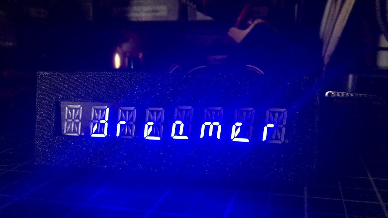
This is a very short demonstration video of a scrolling marquee and random numbers for a 14-segment display project.
Thank you @solar wadi
sand grotto
upbeat lotus
<@375674153203662851> Yup, great observation--I realized that the other night ab...
very interesting, thanks, to be fair the soil sensors are normally so variable that you really care about whole number changes anyway (like <=2 needs some water). Was going to setup good-enough.cloud for similar mqtt/dashboard/long term storage needs as the free offerings always cap the length. I love the offline first though so losing myself a bit there instead of progressing, along with making things which aint so bad.
https://photos.app.goo.gl/qWk8Gv1RB1viL9Nz9


Google Photos
46 new items · Album by Tyeth Gundry
 empty basin
Drop in USB-C upgrade for a meter, no more RS-232 over Throkom connector for me.


Meter in question

 sullen ferry
Proud parent, baby's first 'steps'
Two years in the making 🥹
 worn marsh
My first 'real' project, a portable radio prototype with backup battery, 4 key mechanical controls, and earth-friendly, closeable containment unit. I love STEMMA connectors, and this was easier to do than I thought. Boasts a five hour battery life (with screen off and key neopixels turned off).
 distant marten
worn marsh
My first 'real' project, a portable radio prototype with backup battery, 4 key m...
distant marten
worn marsh
My first 'real' project, a portable radio prototype with backup battery, 4 key m...
Cool! What radio module did you use?
worn marsh
Sec, lemme find it
@distant marten Oh duh, it's the ScoutMakes radio board
The one with the Stemma connectors
Definitely the most expensive stemma peripheral I have that isn't a display, but it's got good features and I like the audio quality with headphones
 scarlet pelican
Some synth work in progress with one of my music technology students here at Georgia Tech: waveshaping circuitry based on the Ondes Martenot (Eurorack format) https://youtu.be/Cp2b6IfX44M
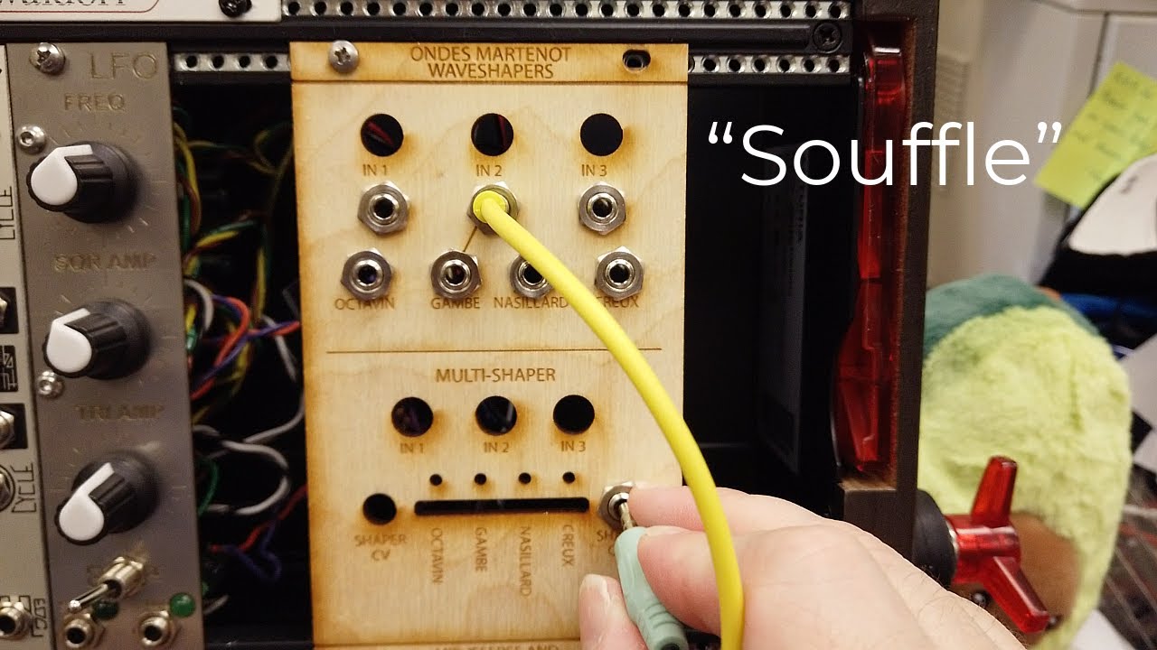
Support this channel via a special purpose donation to the Georgia Tech Foundation (GTF210000920), earmarked for my work: https://youtu.be/VBu-LST1p9c
Work in collaboration with Georgia Tech Music Technology student Mir Jeffries.
0:00 -- Introduction
1:47 -- Sound Demos
#analog
#modular
 wise bluff
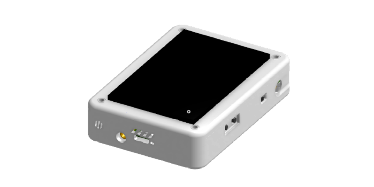
The Cellulith: my latest computer-aided brain child.
https://github.com/AdansWorkshop/Cellulith
GitHub
An RP2040 based IoT/cellular device. Essentially a cell phone but very bulky. - GitHub - AdansWorkshop/Cellulith: An RP2040 based IoT/cellular device. Essentially a cell phone but very bulky.
 carmine flare
wise bluff
The Cellulith: my latest computer-aided brain child.
https://github.com/AdansWor...
carmine flare
wise bluff
The Cellulith: my latest computer-aided brain child.
https://github.com/AdansWor...
This is super cool!
wise bluff
thanks!
sadly the total parts cost is about $500. i have bought $60 worth of the parts so far
sullen ferry
https://youtu.be/7vI-lMrQpLA
Still primitive walking but better than last night, 2 years in the making

Robot dog 'Clifford' designed in Fusion 360 and 3D printed, is up and walking around with a primitive gait.
wise bluff
ok but can it see in blue and yellow and not be able to find a red toy in the green grass
north mural
Twitter, Discord, OpenWeatherMaps, Mastodon, Github, YouTube, Steam, etc... all have their own API's you can easily plug into with GET/POST or CURL requests. Most use 0Auth and some type of token scheme to return JSON data. JSON API's are very easy to work with. This is necessary stuff to learn & know if you want to get your follower count or pipe today's weather to a display.
I was recently added to a game developer team on Steam and asked to use the Steam Partner API to get wishlist request data... except not only does that endpoint not exist, neither does the API for most data on the partner side. Steam also completely removed 0Auth in 2018 and locked down access to pretty much anything on the game publisher side which most of the public cannot see. The only access to metric data which is the lifeblood of a game developer is to view it in a web browser with 2FA, special token access that limits what you can view even in a web browser, or download a CSV file and parse it yourself.
It's not pretty... but I found a way.
The ESP32-S2 itself parses 17K+ rows of CSV data, all just to spit out 5 digits.
I would like to publicly thank @solar wadi for helping with the CSV parsing example and @subtle delta for the circuitpython_csv library available in the community bundle.
north mural
What I was told would be an API project ended needing an automated batch script & CSV parsing solution.
 subtle delta
north mural
I would like to publicly thank <@199811382793863168> for helping with the CSV pa...
subtle delta
north mural
I would like to publicly thank <@199811382793863168> for helping with the CSV pa...
I'm so glad you found it helpful!
raven shale
Living the life of a Data Analyst (broken/unmaintained API and all)! It would be amazing but presumably hard to get a library like numpy and pandas on circuitpython to do more advanced data work on MCUs...
raven shale
Question: Where would you download the CSV file from? If it's from an API, is it possible to use a get request to save it to an SD Card and then open and parse directly on the MCU?
north mural
@raven shale The CSV filename depends on the publisher and game appid. It would kind of be like /user/Ducky/DuckyGame_dateStart_dateEnd.CSV except it's done with publisher ID and appID's I tried very hard to obfuscate all data from the publisher that allowed me access to it and make it very generic so that others can use the method.
If you know it's going to be a CSV project then you can adjust your expectations accordingly and pivot no problem. I think part of the issue is Steam not having an API on the game publisher side. It's just not there. I imagine the reason was somehow related to abusing it in the past so they just removed it for everyone. The infrastructure exists for it, the endpoints just don't exist, there's nothing other than some API's for game key and player inventory management. It's the oddest thing. I mean you can literally manage a game server with their public facing API these days yet you cannot get any metric data about your own game to an API, the contrast in mind blowing.
Most people who use steam to play games or even as admins have a luxurious amount of API data to play with vs the actual game developer.
north mural
You cannot use a GET/POST request on anything within the partner.steampowered subdomain. It must be accessed from a web browser which Circuit Python cannot do. No data scraping possible. That was my first idea and wasted about 3-4 days attempting it. You'd have to do a session hijack which I did try just for fun and was unsuccessful. That kind of thing also breaks the partner TOS. They expect you to only view it in a web browser or download a CSV.
The example I posted is completely legit and within the Steam Partner's TOS. Pretty much any other method would get you banned and the game developer banned.
The rules for steam partners are extremely strict. The strictest I've seen from any "API" I've ever worked with so far. Again I think it stems from some type of abuse that was happening in the past long before I got there. I worked within the rules and parameters of the project to get it done. I'm happy, they're happy, everyone's happy.
raven shale
web scraping with tools like Beautiful Soup also not allowed? I didn't realize they'd be so strict since their API is broken
your demo is really cool to watch
so jobs done either way, even with everything Valve threw at you
north mural
Correct, beautiful soup not allowed according to their TOS. Web scraping within the partner domain is disallowed.
Can you do it? Yes... but it could get your game publisher account banned.
because again, you'd have to emulate a real browser session along with cookies, tokens, keys, TLS, etc.. you'd have to do a session hijack basically.
So what I did was use a logged in session to automatically launch MSEdge. That's kind of a caveat. I used MSedge because no one uses it, mostly, at least not most advanced users. It uses the browser itself to bypass all the authentication stuff. As long as you're logged in and have "remember me" setup it'll work. It's janky, but it works.
Steam think it's a real logged in partner, with a valid browser, browser session, token, TLS, etc... goes to the URL, auto downloads the CSV and bob's your uncle.
exotic sierra
Wait, you can’t use beautiful soup to scrape steam’s website?
north mural
Not on the partner/game developer side for "Sales & Metrics Reporting" no.
on regular public facing steam side yes, no problem. there are different rules for the partner side.
exotic sierra
Ah okay
north mural
Also worth noting it failed on a Pico W and Feather M0. It's a 64kb file so a large amount of RAM is necessary more than the MCU. ESP32-S2 barely gets it done, it's a big file. It would be much smarter to parse it on the PC and then pipe a small file with only 5 digits to microcontroller, then a Pico W would work.
This is just the prototype, a lot of refinements are still needed. Proof of concept, works. 👍
lucid bloom
This is my proof of concept logic analyzer, it's not complete. It listens for speech, then plays the jeopardy think music while it does whisper sst then prompts GPT3.5turbo to analyze the contents. It then displays the number of logical fallacies on the 4 digit display, the 7 LEDs represent how much of what was said was fallacious. It has a USB sound card with microphone as well as an HDMI audio extractor to connect to the TV.


I came up with the idea years ago but had no way to pull it off, with openai APIs it's not all that hard, I got a bunch of previously unattainable projects that I now consider doable.
lucid bloom
A rather appropriate clip to test it on. I wouldn't want to share the illogic stuff I've been subjecting myself and it to.
 calm badge
north mural
I was recently added to a game developer team on Steam and asked to use the Stea...
calm badge
north mural
I was recently added to a game developer team on Steam and asked to use the Stea...
Is that a new thing because I remember seeing a dashboard for gamedevs using data from steam publisher api and big publishers have a lot of options and seemed to be able to tell a lot about their users. That was at an IGDA conference
north mural
lucid bloom
A rather appropriate clip to test it on. I wouldn't want to share the illogic st...
That is awesome. I love how you're training it with news. These should come standard on all TV's and Radio's these days.
calm badge
Like they used this one to check if forum users were lying about owning the game or not, keep track of servers, track ban evasions etc
lucid bloom
north mural
That is awesome. I love how you're training it with news. These should come st...
I have plans for it if it works well I'm gonna have it tweet the audio clips with the fallacy summary and run it near realtime during speeches/newcasts
calm badge
they were a subsidiary of activision so maybe the big publishers have better tools from valve or something
north mural
@calm badge Yeah what they say they're going to deliver at the Steamworks conference and what they've actually done are two different worlds. I watched a lot of their conference videos too just trying to find some way, some hint, on how to interact with the data. The data for game assets, builds, revisions, etc is mostly what they're referring to. It's in-game related stuff. It's completely different from their sales & metric dashboards. It's really hard to explain without showing examples, but I can't because it's private data... and that's kind of how Steam is allowed to not provide better metric tools because it's behind closed doors. They have metrics... but only while viewing it in a browser on their website... or with a Google Analytics integration which is a whole other bag of worms as you'd need yet another integration and 3rd party access.
Public API is awesome, works great. Partner API is almost non-existent and a complete sh***show.
calm badge
north mural
<@1004463581464641606> Yeah what they say they're going to deliver at the Steamw...
That wasn't a valve presentation though, but an IGDA presentation with slides from a activision sub showing their dashboard to track playing in real-time on servers and knowing if someone cheat and trying to figure out if they are ban evading etc. No photography was allowed so this is from memory but they had a grid of all of the forum users with thousands of pages and they said most of the data was from steam publisher api
telling us muggles they knew almost instantly if someone cheated or someone was BS they owned the game on the forums and they didn't might have just been scare tactics though
north mural
I'm talking about the Steamworks conference which is Valve, not IGDA.
"track playing in real-time on servers and knowing if someone cheat" yes you can do that with their API, it's game focused...
try to get metrics about the company's sales, metric data, etc.. is a completely different thing. There is no API for it.
calm badge
my understanding though is that they can't know the email of the peoples who bought the game
so the forum tracking was possibly with other methods
north mural
It's done via steam usernames.... email addresses have nothing to do with it...
calm badge
(the slides showed screenshots from before steam linking afaik)
north mural
Actually they don't even care about the usernames at that level. It's just about metrics, trends, etc.. they're just numbers.
calm badge
anyway I mean it's not like steamworks isn't documented
the data has to come from somewhere
and companies like activision like to put 10 game analytics sdks in their games...
north mural
Ahhh see that's what you'd think and technically correct. There's no documentation for an API that doesn't exist. That's the problem.
calm badge
I never understood the point of sending a keypress or click in-game to 10 game analyics sdks....
oh ya Ive seen the cdkey management thing before as well and the alpha/beta thing live from a smaller developer
north mural
The API just isn't there. As large as their public web api is you'd think there would be something... it's just not there. It doesn't exist for what companies need to hook into their own sales data. You get a CSV file, that's it, no documentation, and a "good luck" kind of thing. You're on your own.
calm badge
like you can give out cdkeys as the publisher (duh I guess) or the testers even internal can get the latest from off steam
north mural
yes that exists, again, that's game related not company metric related.
calm badge
ah I see what you mean
I think I heard that critique before
like the sales data are opaque, no automated way to follow them in timed interval so at one point you dont know if the numbers steams says are real
like they could be underreporting to get a 100% cut on a couple of sales you have no way to really know
I remember an indie telling me what they disliked about their publisher is that they had no idea if the publisher was telling the truth with how many copies were sold
north mural
I made my show & tell don't want to take up anymore space here with general discussions about steam, can take it to general chat if you'd like.
calm badge
but the publisher possibly didnt even know themselves
whoops yeah, sorry about that everyone
feral orchid
lucid bloom
This is my proof of concept logic analyzer, it's not complete. It listens for sp...
nice
Capacitive macropad business card PCB. Just need to add an RFID coil on the back.

 crisp robin
I have finished my maker faire project with 12 hours left. It is a midi controlled kick drum. It uses Daisy Seed to get midi via USB. Then it turns on and off a relay that controls a car door lock actuator. That pulls a kick drum pedal and is hitting an canvas. The midi routing is done via Cycling74 Max. Thank you everyone for your help. The midi controller is an Arturia KeyStep. https://www.instagram.com/reel/CqeYM0Jrw3I/?igshid=YmMyMTA2M2Y=
Welcome back to Instagram. Sign in to check out what your friends, family & interests have been capturing & sharing around the world.
crisp robin
Here is a vimeo link of the video above https://vimeo.com/813747356

This is "Kick clap speaker - mechanical drum" by Edward Deaver, IV on Vimeo, the home for high quality videos and the people who love them.
 subtle lynx
We made a little something to demo our Bluetooth sound system at work. It's a Raspberry Pi based Bluetooth receiver / player, so that you can control the sound settings and the song from the little round display (details in the description). Lots of fun! Wish the Pi Zero 2w were in stock so we could hide the pi behind the display entirely, but oh well. https://youtu.be/tSuPlj7W_hE

Raspberry Pi 4
Pimoroni Hyperpixel 2.1" round display
Custom OS built with Yocto Project
User interface built with Qt/QML
Backend services written in C++
Bluetooth streaming to our sound system with special DSP controls (built on an ESP32 in C/C++)
And a little magic in the last half. Don't miss it!
stark latch
Initial test of a digital picture frame using a Raspberry Pi Zero W. Testing to verify that the RPi can load and cache several images, then cycle through them with a reasonable response time (sub-second).
Current setup is using an HDMI monitor for display and a mouse click to cycle through the images. The app takes quite a while to load and cache the images but once they're cached, it's able to cycle through fairly quickly.
Intent is to eventually mount this in a frame with an HDMI display and a face-detecting camera (Useful Sensors' Person Sensor) triggering the images. Hoping to be able to have it change images only when the camera detects no faces, so that it appears to be stationary when viewed but changes when the viewer turns away.

Initial test of a digital picture frame using a Raspberry Pi Zero W. Testing to verify that the RPi can load and cache several images, then cycle through them with a reasonable response time (sub-second).
Current setup is using an HDMI monitor for display and a mouse click to cycle through the images. The app takes quite a while to load and cac...
north mural
Round 2 of the Steam Partner CSV parser. Swapped out the ESP32-S2 as the parser for a Python script on the PC. Files parse almost instantly and output only a 200 byte file (less than 1KB) to the ESP32-S2 which it handles instantly. This means I can use pretty much any Circuit Python capable board to run the display now.

Are you searching for Steam's Partner Sales & Reporting JSON API? It doesn't exist, stop looking. The only option Steam currently supports is CSV exporting or Analytics integration. This demonstrates about 90% of the process for automated exporting and parsing of CSV data for Steam Game Developers. This demonstration will be of tremendous help t...

 edgy matrix
Raspberry pi pico
 cursive pewter
This is a guitar effects pedal I've been working on. It uses an Itsy M4 and a 2" 320x240 display. I'm really grateful to Adafruit for making these components accessible and interoperable. In one of the photos you can see a light pipe poking up through the PCB - I mount the pins on my Itsy the wrong way round so the on-board NeoPixel can be used as a tempo indicator.

 north mural
Creative board design to do that on purpose. Have a link to your project?
cursive pewter
north mural
Creative board design to do that on purpose. Have a link to your project?
Only the product website - roundersounds.com. Is that what you mean? I'm new on Discord today.
north mural
Oh usually things are open source here for github documentation but I think that’ll do.
Very nice case!
cursive pewter
north mural
Oh usually things are open source here for github documentation but I think that...
Ah! The case is actually a simple aluminium 1590BB box with some rough holes cut in it using a jigsaw, then a nice aluminium PCB made by JLCPCB to cover up the rough saw work. I made the lettering using both the top layer and the top solder mask layer to get silver print.
About a dollar per top plate : )
north mural
Ahh thats a neat idea. How does it hold up with feet smashing it.
The silkscreen i mean.
cursive pewter
Pretty well so far. I'm only little though 😄
It dulls a bit with time, but still contrasts well with the black
distant marten
cursive pewter
Ah! The case is actually a simple aluminium 1590BB box with some rough holes cut...
That’s really clever!
 gray loom
Hey all I just wanted to share this project I've been working on, you can find it at: https://dopplerai.com and the API endpoints here https://dopplerai.com/swagger.
It's an API that gives AI access to memory and specialized knowledge. Simply upload files or plain text via API calls and the API will handle everything from there. Memory and knowledge are optional and you just make a simple API call to access all the knowledge you've uploaded.
It was made with multitenancy in mind so if you want to allow each of your own application's user to be able to upload their own data (not accessible by any other user), you can do that.
It's particularly useful if you want to make an AI Hardware as a Service product. I originally bootstrapped a hardware business and wanted to add an AI component to it. This was back when we were still in the realm of GPT-3. I found doing embeddings over vector databases to be much harder than expected so I initially made this for myself.
If you're curious, it abstracts over a vector database, a traditional SQL database and Langchain.
The SQL database is used to extract and store additional metadata. The API handles interactions between your application's users and the vector database, so you don't need to implement users or figure out how to do separation of data for each user in the vector database.
north mural
@gray loom Now that's a good example of well laid out API documentation. Far better than you get with a lot of API's. Reminds me of YouTube's API documentation which is exceptionally good. This type of documentation schema looks easy to work with. 👍
Having examples for CURL & GET/POST requests with every endpoint makes the documentation long but API developers can be much faster with integrations if they have examples for every parameter or key:value pair to plug into. I don't know if this type of documentation was inspired by Youtube's API's or it's a template system that does it. In any case, it's a great format for API documentation, well done. Nice looking project.
Embedded designers don't have the option of using an API framework like beautiful soup. We require GET/POST/JSON for everything from a microcontroller so having those examples built in is appreciated. I hope all API's start using this type of documentation method in the future. Steam for sure could definitely use a complete revamp using that style.
@gray loom I don't know what type of API templating system this is but it's excellent. For API devs this is the kind of stuff I like to see. 👏
 gray loom
Wow thanks so much! 😄
gray loom
I used Swagger to create the UI portion of the API docs there. You can find it here https://swagger.io/tools/swagger-ui. It does take some time to configure it though.
lucid bloom
Today I took my AI logic analyzer concept to it's next logical conclusion, correcting logic on Twitter, it's currently running on a pi 4 but I'll downgrade to a pi 3 or possibly a pi zero w. I'm not done so it's not ready for general use yet but will be soon.
 north mural
@lucid bloom That is good. Twitter is an excellent training ground for it.
lucid bloom
I am having a lot of fun with it, it will respond directly to a tweet where it is mentioned with an analysis. if that tweet is part of a thread it will analyze the whole thread and name the users who committed each fallacy. if it was already invoked on the thread "it will say sorry @clever cloakever I can't do that" I'm not sure what else to make it do before I share it for general use. it occasionally crashes with a response that it a little too long
drifting crater
Small project I have been working on - the hard parts are over, (soldering and multiplexing) time for some animations!

 crimson egret
@ancient skiff Thanks for showing the mixer demo of the m7 with up to four channels. I'm currently waiting for an order to get to Costa Rica, as I'll be trying on how many channels I can get on some esp32*-qt. I must test it with m7 when they are back in stock. This is the project that I'm building.
 ancient skiff
I don't specifically know, I was interested in testing the m7. I'll be interested to hear your findings.
crimson egret
So, this is a pedal like the ones that are used for guitar and bass (which @fair vessel has made some cool ones), but this one uses a python library called "demucs" from facebook, that un-mixes any song into four tracks, drums, voice, bass and others (which includes the guitar)
https://www.youtube.com/watch?v=_IGj-wyZRRc

So it's like a super-karaoke machine. Of course you can use it like a tradicional karaoke machine, but can also mute all the channels and leave the guitar channel, so that you can listen a specific instrument for practice, transcription, recording, etc.
So it should be quite useful if someone plays guitar, or bass, or drums, or for singers, keyboard players, etc.
 jagged canopy
drifting crater
Small project I have been working on - the hard parts are over, (soldering and m...
jagged canopy
drifting crater
Small project I have been working on - the hard parts are over, (soldering and m...
can I make some animations?
drifting crater
jagged canopy
can I make some animations?
I'll post the code later so then you can modify it to add more
jagged canopy
drifting crater
I'll post the code later so then you can modify it to add more
please dm it to me too
carmine flare
crimson egret
So, this is a pedal like the ones that are used for guitar and bass (which <@347...
Really cool! Does it do the separation on the fly or is it pre-rendered?
crimson egret
carmine flare
Really cool! Does it do the separation on the fly or is it pre-rendered?
Because of how the demixer algorithm works, it doesn't not support in-the-fly. It is pre-rendered, but it should be really quick to add new songs to it.
This current version is running on a raspberry pi4 because I wanted to have that demo working asap, and it's using azure functions to split the tracks.
crimson egret
crimson egret
So, this is a pedal like the ones that are used for guitar and bass (which <@347...
BTW, the code for this imitator pedal is here. I still need to work on the azure functions code, and to add some more diagrams and documentation so that anyone can replicate the project, but if someone needs help, ping me out.
https://github.com/fede2cr/pedales/tree/master/imitator

GitHub
Pedales y efectos para guitarra, bajo y otros instrumentos. Sencillos de construir. - pedales/imitator at master · fede2cr/pedales
feral orchid
Qwiic INA237. Any suggestions?

 feral orchid
I2C controlled tDCS/precision constant current source

 ancient skiff
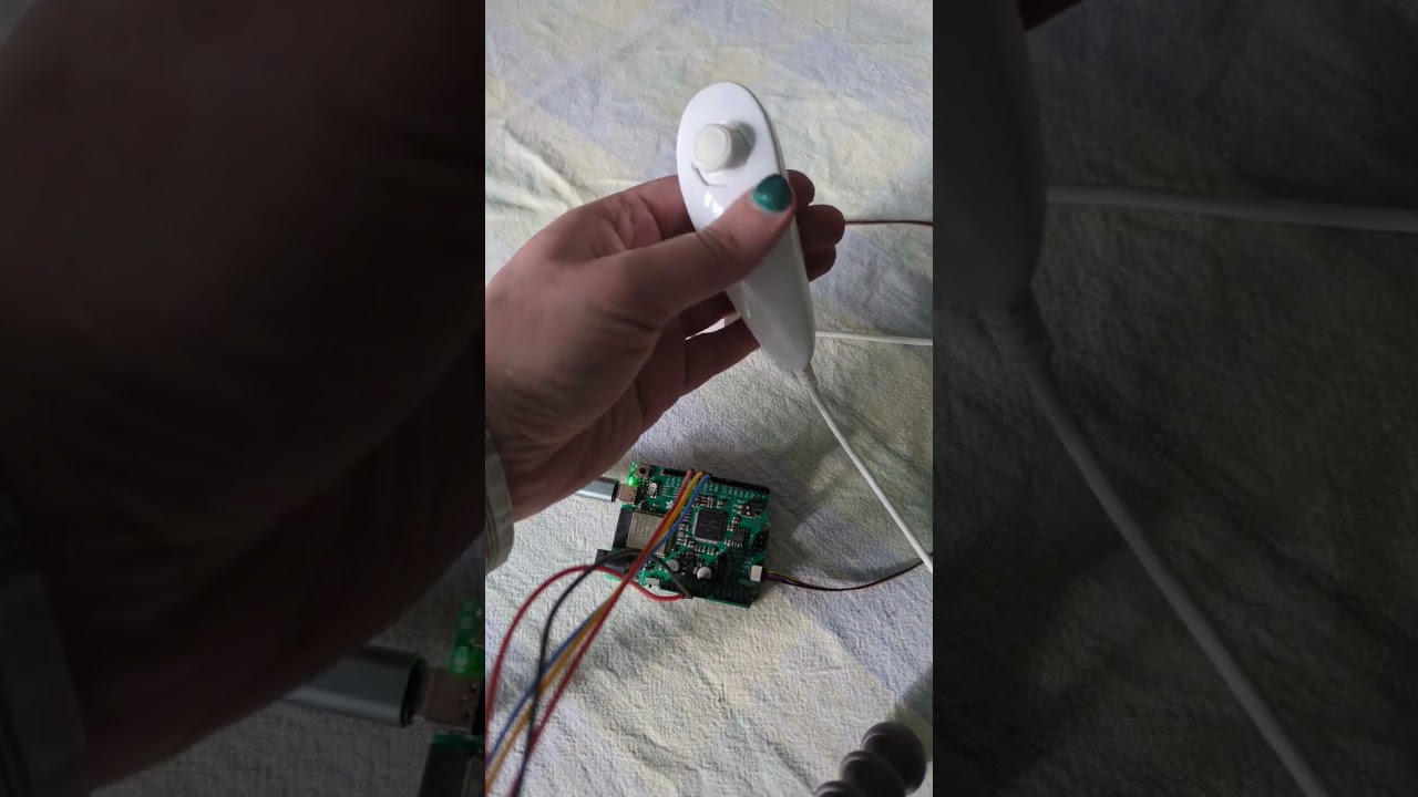
Jepler is improving real time audio synthesis in #circuitpython -- pull request at https://github.com/adafruit/circuitpython/pull/7825
 solemn vector
pretty cool!
drifting crater
drifting crater
Small project I have been working on - the hard parts are over, (soldering and m...
(I've added some basic animations and posted the code and schematic on GitHub: https://github.com/UnsignedArduino/Nano-3x3-LED-Cube)
drifting crater
drifting crater
(I've added some basic animations and posted the code and schematic on GitHub: h...
@jagged canopy
jagged canopy
drifting crater
<@737379291490418698>
Okay thanks
 hushed needle
Keyboard of my design that's running KMK which is a firmware written and configured in Circuitpython.
https://github.com/KMKfw/kmk_firmware


GitHub
Clackety Keyboards Powered by Python. Contribute to KMKfw/kmk_firmware development by creating an account on GitHub.
distant marten
hushed needle
Keyboard of my design that's running KMK which is a firmware written and configu...
Ooooooo, is it made from stacked acrylic?
hushed needle
distant marten
Ooooooo, is it made from stacked acrylic?
Yes, the main PCB is sandwiched between the sheets of acrylic
distant marten
hushed needle
Yes, the main PCB is sandwiched between the sheets of acrylic
It looks really cool!
hushed needle
Thanks!
 wide star
I was tired of messy and broken wires on LED projects, so I designed this LED driver board. There are pads on the board so your LED strip can be soldered directly on. This gives a solid connection point for the LED strip. It has an ATMega32U4 and can be programmed with the Arduino IDE. It's compatible with Neopixel and Dotstap LED strips, among others. There's a barrel jack for extra power input, USB-C, and an extra button you can program. I just put them on my Shopify. https://highintensitylabs.com/products/led-mango


HighIntensityLabs
Introducing the LED Mango - an innovative microcontroller circuit board that allows you to create amazing lighting effects with individually addressable LED strips. Designed with an Arduino-compatible microcontroller, the LED Mango has a unique connector that enables you to easily solder your LED strips directly onto t
north mural
@wide star That's a great idea. The Adafruit Scorpio was designed specifically for a similar purpose but it doesn't have the external power included. Well done.
wide star
north mural
<@391607505177804801> That's a great idea. The Adafruit Scorpio was designed sp...
Thanks. The Scorpio is a cool board. I would like to make a RP2040 version of the LED Mango at some point.
 pure yew
Hi! Where does the show and tell tonight sign up list live? Thanks
 scenic siren
pure yew
Hi! Where does the show and tell tonight sign up list live? Thanks
scenic siren
pure yew
Hi! Where does the show and tell tonight sign up list live? Thanks
Check out the #live-broadcast-chat channel. A link will be posted there to join when it's time.
pure yew
scenic siren
Check out the <#330406870256975873> channel. A link will be posted there to join...
thank you!
 rain charm
@north mural good job with the show and tell
north mural
@rain charm Thank you. It's really hard trying to explain a complex project in a minute or two.
rain charm
the project had a lot and you broke it down well in the short time
was cool to hear how you parse the csv and convert to a format you can work with over various pieces of hardware
 rough root
I made a terrarium in a class today. Thinking of ways to add sensors for temp and humidity. Maybe a qi pad?

 rain charm
is that micro greens?
like little watermelons and brocoliS?
and a pickle?
it's amazing what u can do inside of a jar these days
feral orchid
rough root
I made a terrarium in a class today. Thinking of ways to add sensors for temp an...
qi would be a cool option. Even cooler would be a micropower solar energy harvester
rough root
I think qi is easier haha
rough root
rain charm
and a pickle?
It's moss from around town, a spider grass thing, volcanic rocks, and something else
rain charm
c ool
sullen ferry
Not bad for an afternoon's work!! Lamp runs off 4xAA or USB-C. Tycho supernova remnant model from NASA's 3D model repository. Designed the lamp from scratch. Spectacular amount of depth to your eye, camera is not even close 😦


 lean elbow
That looks so cool!
rough root
Made this sleeve for my depth gage.
 crisp robin
So last weekend was Syracuse's Maker Faire and I used a Daisy Seed/MaxMSP to make an electromechanical kick drum controlled via MIDI for it. I wrote a blog post about it here: https://edwarddeaver.me/blog/making-of-midi-kickdrum-maker-faire/ and here is a short video of it: https://vimeo.com/815262283 Thank you everyone so much for your help.

Edward C Deaver IV
I wanted a project that would combine a few interests of mine and make for a cool exhibit at Maker Faire Syracuse. This was filled with firsts. First time exhibiting at Maker Faire, first time making a MIDI Instrument, first time making an electromechanical instrument first real MaxMSP patch.

This is "SyracuseMakerFaire - 2023" by Edward Deaver, IV on Vimeo, the home for high quality videos and the people who love them.
spiral scaffold
Special thanks to adafruit for selling their extra W25Q64JVXGIQ memory chips in packs of 10! The perfect number for testing new rp2040 designs.
 runic sorrel
Custom mPCIe to PCIe adapter for my Google Coral!
 feral orchid
First test of the jank overcomplicated weather station. Logging to adafruit io every 5 minutes. I designed this a while ago but I haven't started much of the code work until now lol. Still, it will eventually go in a weatherproof enclosure to monitor the weather

Temp data
 north mural
Data looks pretty good. I love seeing weather related projects. They're a great entry into automation and you can upgrade them slowly pretty far with additional outdoor sensor setups.
Didn't know Sparkfun had boards for that kind of thing. That's great!
 hollow marsh
https://viacondioscustoms.com/
WattsonDaCat is a cat shaped metal lamp Original Design by yours truly !!
- Durable Metal Construction
~ Night Light
~ USb ports
~ Magnetic ears and paw
~ Bulb encluded
…Supplies are limited so PLEASE Reserve YOURS now before it’s too LATE =UwU=
33% OFF SALE!!
ONLY AT Viacondios Customs

 pulsar mortar
Weekend welding project


 pallid saffron
Cobbling things together
https://photos.app.goo.gl/SfjahBZ6V3BfbYdF6
Hardware:
- RaspberryPi 3B+
- various LEGO/Technic parts
- Adafruit CRICKIT Hat https://www.adafruit.com/product/3957
- GPIO breakout https://www.amazon.com/gp/product/B08RDYDG6X
- Ultrasonic sensor https://www.adafruit.com/product/3942
- Grayscale 128x128 OLED https://www.adafruit.com/product/4741
- Sparkfun QwiicHat https://www.adafruit.com/product/4688 (not v2 because it blocked the CRICKIT)
- "control buttons" (4 out of sight to the left) are copper tape applied to LEGO
- SG90 servo (wedged in underneath all that)
Basic operation: there's some "control" pads that turn on various functions (like enabling the screen) and everything runs for a set period of time before going idle. Ultrasonic is connected via the GPIO expander (the CRICKIT is "too slow" in this instance to get readings), the CRICKIT runs the servo and touchpads for the "buttons", and the screen is being rendered off of the QwiicHat. The screen shows time, CPU temperature (gauge on left) and a "radar screen" showing pings from the range-finger at 0-40cm.
Now here's the very interesting part: the code is written in Kotlin and running with Java 17. The base library that allows this magic is https://www.diozero.com/ (disclaimer: I have become a minor contributor)
pallid saffron
(if anyone's following here, sorry about all the edits - trying to figure out video sharing)
north mural
Finished the alphanumeric display project. Very happy with the final design and features. https://www.youtube.com/watch?v=zm0cvGM-3JI

Demonstration of final prototype. Includes on/off power button, two way tint film as LED diffuser, 1/4"-20 standard camera screw mount, USB power with 150mah battery charger, printed in Polymaker 2-color Silk PLA.
 calm copper
We made Neopixel Nano sequins.
 north mural
That’s a neat idea. Great little PCB design to make that happen!
 sharp gale
First big project, eventually going to be a midi controller/drum pad in the style of a mechanical keyboard.
Even got the space bar for sustain 😉
Features Complete:
Button matrix worky,
Extra buttons worky
Midi out
Octave changing (midi mode)
Features remaining
Sustain bar
Mode switching
Sound box mode
Volume/Velocity knob w/ indicator LED
Velocity randomizer knob w/ indicator LED
Indicator LEDs for octave position, power, and mode
import keypad
import board
import time
import random
import usb_midi
import adafruit_midi
import digitalio
from adafruit_midi.control_change import ControlChange
from adafruit_midi.note_off import NoteOff
from adafruit_midi.note_on import NoteOn
from adafruit_midi.pitch_bend import PitchBend
from digitalio import DigitalInOut, Direction, Pull

# Set usb midi channel
midi = adafruit_midi.MIDI(
    midi_in=usb_midi.ports[0], in_channel=0, midi_out=usb_midi.ports[1], out_channel=0
)

#defines default octaves
octleft = 4
octright = 5

#initialized key matrix
km = keypad.KeyMatrix(
    row_pins=(board.GP0, board.GP1),
    column_pins=(board.GP2, board.GP3, board.GP4, board.GP5, board.GP6, board.GP7, board.GP8, board.GP10, board.GP9, board.GP11, board.GP12, board.GP14),
)

#defining none-midi (non-matrix) inputs
down = digitalio.DigitalInOut(board.GP21)
up = digitalio.DigitalInOut(board.GP20)
mode = digitalio.DigitalInOut(board.GP19)
alt = digitalio.DigitalInOut(board.GP18)
sus = digitalio.DigitalInOut(board.GP22)

#array contianing buttons
buttons = ["up", "down", "mode", "alt", "sus"]

#setup buttons
up.direction = Direction.INPUT
up.pull = Pull.UP
up_ran = False

down.direction = Direction.INPUT
down.pull = Pull.UP
down_ran = False

mode.direction = Direction.INPUT
mode.pull = Pull.UP
mode_ran = False

alt.direction = Direction.INPUT
alt.pull = Pull.UP
alt_ran = False

sus.direction = Direction.INPUT
sus.pull = Pull.UP

#start of loop
while True:
    #defining variables and such
    mode = 0

#defines notes for the key matrix
    notemap = [
    f"C#{octleft}", f"D#{octleft}", f"F{octleft}", f"F#{octleft}", f"G#{octleft}", f"A#{octleft}", f"C#{octright}", f"D#{octright}", f"F{octright}", f"F#{octright}", f"G#{octright}", f"A#{octright}",
    f"C{octleft}", f"D{octleft}", f"E{octleft}", f"G{octleft}", f"A{octleft}", f"B{octleft}", f"C{octright}", f"D{octright}", f"E{octright}", f"G{octright}", f"A{octright}", f"B{octright}"]

    #octave change code
    if down.value is False and down_ran is False: #down_ran varible used to create only 1 input per key press.
        midi.send(ControlChange(123, 1)) #ControlChange(123, 1) stops all midi notes. This prevents "infinite note" bug when changing octaves.
        if octleft > 1: #Locks controller to usable range.
            octleft = octleft - 1
            octright = octright - 1
            print(octleft)
            print(octright)
            down_ran = True
        else:
            print(Lower Limit Reached) #Place holder for "Limit hit" LED
    elif down.value is True and down_ran is True:
        down_ran = False #resets down_ran on key release so that octaves can be changed

    if up.value is False and up_ran is False:
        midi.send(ControlChange(123, 1))
        if octright < 8:
            octleft = octleft + 1
            octright = octright + 1
            print(octleft)
            print(octright)
            up_ran = True
        else:
            print(Upper Limit Reached)
    elif up.value is True and up_ran is True:
        up_ran = False

    if mode is 0: #Mode 0 is midi mode
        ev = km.events.get()
        if ev is not None:
            key = notemap[ev.key_number]
            if ev.pressed:
               midi.send(NoteOn(key))
            else:
                midi.send(NoteOff(key))```
Photo jank, lighting bad
stark latch
Managed to get that interactive digital picture frame (sort of) working.
https://www.youtube.com/watch?v=K9OVkpTOJ0g

Uses a Person Sensor and a Raspberry Pi Zero to detect when a person turns away from the frame, and update the displayed image.
 arctic peak
I rebuilt an animatronic brain I use as my avatar when streaming on Twitch. It uses the mini Pan-Tilt kit hidden under the jar lid to control the motion and a bunch of NeoPixels for lighting (dots and rings). Some NeoPixels are sewn right into the foam brain with conductive wire. The whole thing is controlled by an arduino board getting serial data from a PC. The PC is tracking my head position to send yaw & pitch angles to the servos and performs an FFT on my voice to control the light values. This lets me puppeteer the brain completely hands free. The jar is filled with non-conductive mineral oil for effect.

 dim saddle
QT Py ESP32-S2 running the latest Flipper Zero Wifi Dev Board port of the ESP32 Blackmagic Probe Wifi Debugging firmware. Still working on UART, I2C, NeoPixel (RMT), and other mappings that aren't cooperating out of the box, but remapping SWDIO and SWCLK to SDA and SCL has it purring over wifi (using toolchain-rp2040-earlephilhower/bin/arm-none-eabi-gdb).

I'll probably end up borrowing the idea of using a stemma cable with breakouts that someone did for the QT Py RP2040 Picoprobe.
distant marten
dim saddle
QT Py ESP32-S2 running the latest Flipper Zero Wifi Dev Board port of the ESP32 ...
Ooooooh, have you had good experiences with the BMP firmware on ESP32?
dim saddle
It runs fine for me using the flipperdevices fork. They've kept it up to date with upstream BMP.
and yeah using it over wifi directly is sooooo nice. Can debug from across the room without having to sit next to what I'm debugging.
(I've been using a back-to-ESP32 port I did of an older version of the Flipper Zero port on a TinyPico for some time, but it had issues with RP2040 due to the age of its codebase)
distant marten
dim saddle
and yeah using it over wifi directly is sooooo nice. Can debug from across the r...
That's amazing, it's huge for debugging devices that might be connected to high voltage too!
dim saddle
very true!
Major kudos to the Flipper Zero team for keeping it up to date.
Anyway, I'll post my fork for the QT Py once I get the blasted LED working.
distant marten
That's awesome!
dim saddle
(but if anyone's in a hurry, it's completely functional over wifi with just the SWDIO/SWCLK changes in components/blackmagic/esp32-platform/platform.h)
 obtuse brook
I created cursed library, please rate 0/10 of curse-o-meter
https://github.com/handmade0octopus/CursedDoubleLinkedListInterface-library

GitHub
Cursed Double Linked List Interface for C++ and Arduino - GitHub - handmade0octopus/CursedDoubleLinkedListInterface-library: Cursed Double Linked List Interface for C++ and Arduino
distant marten
obtuse brook
I created cursed library, please rate 0/10 of curse-o-meter
https://github.com/...
Outstanding
obtuse brook
distant marten
Outstanding
thank you
distant marten
My rating:
- use of templates: automatic +3 curse
- class name is an acronym: +1 curse
- mere mention of ChatGPT: +4 curse
- iterator for "auto" support: -1 curse
- entire library exists in 1 header file: -1 curse
Total: 6/10 cursed
Thoughts to increase curse level: make it circularly-linked lolololol
obtuse brook
distant marten
My rating:
- use of templates: automatic +3 curse
- class name is an acronym: +1...
yeah.. this is another idea 😄
I may actually need it for my project
distant marten
obtuse brook
yeah.. this is another idea 😄
Bonus points for including a separate iterator that will infinitely iterate over it
obtuse brook
distant marten
Bonus points for including a separate iterator that will infinitely iterate over...
if I find use 😄 Joking aside I am really using this in my project
as its something I need (especially nested linked lists)
distant marten
Oh for sure, it's pretty compact!
I use plenty of cursed stuff. Kubernetes, for example
 solar yew
i made my first working PCB! Yay!
north mural
Designed a workbench light with built-in fume extractor and webcam mount. For youtubers who regularly film electronics projects. Mount could also be used for a microscope instead of a webcam which I do have to swap back and forth between sometimes. Electronics not included just a 3D printing model. https://www.printables.com/model/452082-solder-webcam-lamp

Printables.com
Combines workbench lamp, fume extractor, and webcam mount. | Download free 3D printable STL models
Sometimes I just need the light, sometimes the light and webcam, sometimes the light and fume extractor. This solves all the scenarios I need it for.
I came this 🤏 close to designing it like Deep Space Nine. Maybe in a future revision. 🖖
solar yew
vio terminal
dim saddle
distant marten
That's awesome!
Still haven't got the neopixel working (timer issues that are ironically difficult to debug with my current setup - I don't have any other S2 boards at the moment), and made a bunch of probably unnecessary changes enroute, but https://github.com/litui/blackmagic-esp32-s2/tree/qtpy-esp32s2 for the basic wifi SWD debugging.
It's now using a STEMMA cable for the SWD probing on pins 40 and 41.
I did this for a purpose so I'm working on that purpose now, but I hope to return to this and fix what's broken on the QT Py down the road. It's a devastating little wifi debugger 🙂
GitHub
A fork of the Flipper Devices Blackmagic tree to port to some other devices. - GitHub - litui/blackmagic-esp32-s2 at qtpy-esp32s2
distant marten
dim saddle
Still haven't got the neopixel working (timer issues that are ironically difficu...
That's so cool, starred! Also I haven't heard of Svelte before but something that compiles to small, vanilla JS? yes please
dim saddle
distant marten
That's so cool, starred! Also I haven't heard of Svelte before but something th...
I gotta say I don't like that it's insecure by default. Will probably change that. But the convenience outweighs the security right now.
distant marten
dim saddle
I gotta say I don't like that it's insecure by default. Will probably change tha...
Fair, though I'd hate for the encryption overhead to impact the debugging experience
dim saddle
I don't think the overhead should be huge as the S2 has AES and SHA acceleration in hardware.
distant marten
Ahhhh that makes sense
 shy fossil
Just a couple of FDM prints because I am pleased my printer is working


A multi gimbal test print, and an 8mm socket for turning Eurorack nuts
 short summit
hollow marsh
(╯°□°)╯︵ ┻━┻
short summit
hollow marsh
(╯°□°)╯︵ ┻━┻
Yeah, autobot flagged the name of the robot as it's short for a swear word
hollow marsh
Oh
hollow marsh
short summit
Yeah, autobot flagged the name of the robot as it's short for a swear word
Nope I took out the word 🤖
Oh
Functional BT robot and charging station with strobing eyes 👀 name M o Fo 2.0 all metal construction 🚧 made by this guy “ViaConDios”

I actually need to paint and rebuild this guy. I was stealing parts to try a few things out on my second BT stereo robot named DaBruce.. thanks for viewing have a blessed day!!
 wooden snow
I just made a small library for arduino called MicroMath with full complex support and special math functions https://github.com/Bobingstern/MicroMath

GitHub
Full complex support and a bunch of special math functions for Arduino Microcontrollers! - GitHub - Bobingstern/MicroMath: Full complex support and a bunch of special math functions for Arduino Mic...
 tepid socket
Etch-a-Sketch, but digital :D, but you will need some basic electronic components and a microcontroller:
https://kyuchumimo.itch.io/serial-a-sketch

itch.io
 vernal vigil
Almost ready for first test...
 vernal vigil
OK ready for the second test now 😅

 rancid kestrel
E-fidgets will be on this week's S&T ☺️
 north mural
Figured out a way to pipe the FPV (first person video) camera into OBS to record a short demo. It's a lot of fun to play with not gonna lie. 🙂
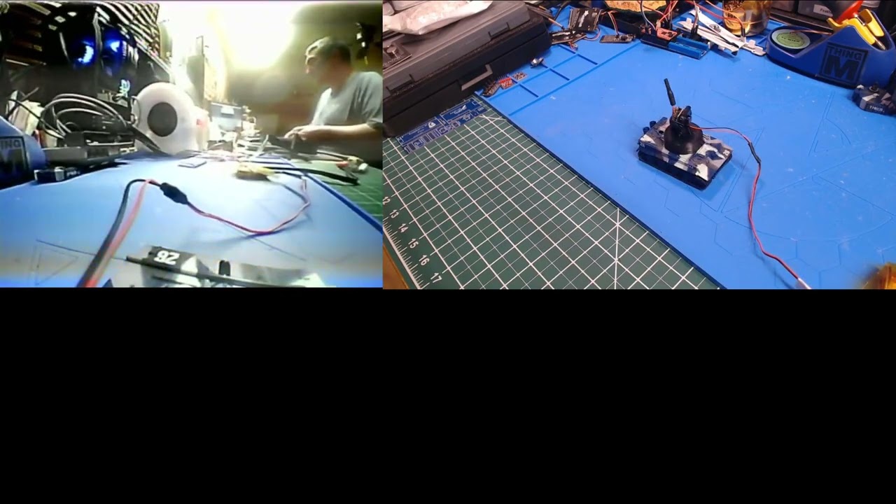
Custom 3D printed RC tank turret replacement with FPV camera mount. This is testing piping the FPV video feed through an AV to USB2.0 video converter into the PC (OBS capture). Hopefully a future sewer inspection bot in the making.
Anecdata in Adafruit Discord said I always have some new whizz-bang creation every day. In honor of all of his am...
 reef river
Nothing super fancy here but helped out my shooting club with a target that was destroyed in a few floods. The target has two places to hit and when you did, it would open a micro switch to trigger lights and sound of a coyote howling. I used a trinket pro connected to a sound fx board. Still have a micro switch to trigger the sound and lights to signal the successful hit. Just have to figure out how to make the audio louder now.
north mural
You can pipe the audio signal to a bigger amplifier and more powerful speaker.
20W amplifier with 20W speaker. The amplifier should always have the higher wattage capability than your speaker.
2x 10W speakers = 20W and so on.
empty basin
I suppose this was a "project", ran a booth at the local maker faire Saturday, had a great time, lots of people had fun playing with the meters, did some physics demos, and got to share the things I love with folks.
 feral orchid
Got the weather station outside. MPPT charger works. It sends data. Just have to mount it and make sure the code is (mostly) bug-free. If anyone chooses to use a CN3795 based MPPT charging board, it only works if you actually hook up a solar panel to it. For whatever reason, it refuses to work when powered by a bench PSU.


The stuff in the box will be held down by screws when it's actually mounted. This is a crude test
lean elbow
Had so much fun building one that I built two more 😵💫
Also wrote custom code to take advantage of the RGB in the RGB button, to prevent the same sound from playing twice in a row, to make the motion detection work on all 3 axes, and to smooth out the blade LED animations between state transitions. Also I made one of them pink because why not
lean elbow
 graceful sleet
Supercharge Your Breadboard! #TindieBlog #Breadboard #PowerSupply #USBC
https://blog.tindie.com/2023/04/supercharge-your-breadboard/

There are lots of breadboard power supplies out there, but they tend to have the same limitations — one, maybe two voltage rails, and fairly low current limits. Well, this Mini Power Station …
feral orchid
Moar weather station testing. For some reason, yesterday's test only sent data 5 times (it sends data once a minute) during the whole 20 hour period it was on. I don't know why that happened, but now it's fixed after I updated the code. (It might have been some sort of memory issue)
 feral orchid
rancid kestrel
E-fidgets will be on this week's S&T ☺️
feral orchid
rancid kestrel
E-fidgets will be on this week's S&T ☺️
How did you get on Show and Tell?
devout verge
feral orchid
How did you get on Show and Tell?

Adafruit Learning System
Show us what you are working on weekly on Adafruit's Show and Tell broadcast
fathom summit
Custom design and code, finished :)
Implemented scrolling text yesterday but it is still a little buggy 😬
top-left: date and time
top-right: weather forecast and active window on the PC
computer's CPU usage went high while compiling some code
button on the right triggers a telegram's bot message
slider could control the brightness of a domotics bulb, but i dont have one lmao
i'd love ideas for more info to show, or triggers to execute 😉
 languid nebula
Some time ago, I told @west zinc that I wanted to do a clock with the dial library. Thank you for all your work in that amazing library! This is made with simple_dial library in the community bundle and CircuitPython 8.1.0 beta 2. Thanks to Neradoc for the example code.
exotic sierra
languid nebula
Some time ago, I told <@366059101203202052> that I wanted to do a clock with the...
Thank you for this, I need this for a watch I made 🥳
 sharp bobcat
Hi folks. I have since been playing with the enclosure for my lora project, so it is not a cardboard box anymore. 😉 STLs and pictures are in the repo now: https://github.com/flavio-fernandes/lora-ben/blob/main/3d-print.md fun times!

GitHub
iot sensor gizmo for Ben. Contribute to flavio-fernandes/lora-ben development by creating an account on GitHub.
north mural
Would probably better decribe it as a LORA river water level sensor project. Very involved project, seems to have come out very well. Nice 3D design and printing too. Well done!
north mural
I just want to share that my weather station popped up a storm warning again today and sure enough after checking my local weatherstation radar there's a big storm out there. It not only works well but works reliably.


The way it accomplishes it is super simple.

Bosch has stepped up their game with their new BME280 sensor, an environmental sensor with temperature, barometric pressure and humidity! This sensor is great for all sorts of ...
that's it, that's all, 1 adafruit sensor.
 eternal maple
north mural
I just want to share that my weather station popped up a storm warning again tod...
eternal maple
north mural
I just want to share that my weather station popped up a storm warning again tod...
Your at-scale testing setup is impressive.
... and congratulations. Excellent project.
feral orchid
north mural
https://github.com/DJDevon3/My_Circuit_Python_Projects/tree/main/Boards/espressi...
What is your weather station sending data to? I'm using Adafruit IO because it works well and the API was easy, but I ran out of feeds
north mural
@feral orchid It's not sending any data only receiving. I have a separate WipperSnapper sitting behind it that sends data to AdafruitIO. Eventually yes I would like to send data directly from it to AdafruitIO. Recently got into MQTT for the first time and slowly moving towards getting MQTT hooked into it along with NOAA weather maps. OpenWeatherMap closed their 1.0 API for anything map related... basically you have to pay for anything to do with a map now. So I switched over to NOAA and almost immediately found a simple gif they provide that is a nice replacement.
north mural
Here's the NOAA url you can customize to spit out a regional gif for your region. https://radar.weather.gov/region/conus/standard
north mural
Got 2 motors working with the servos today. They're more like plane propellers or motors for a fast RC car. I need a slow crawler not a race car. Have some reduction geared motors coming in and will try those next. Turning the sewer tank bot into a high gain RC tank. Toy controller that comes with it only goes about 20feet. Upgrade progress.
 distant marten
north mural
Got 2 motors working with the servos today. They're more like plane propellers o...
distant marten
north mural
Got 2 motors working with the servos today. They're more like plane propellers o...
Are you planning to control this thing wirelessly?
north mural
distant marten
Are you planning to control this thing wirelessly?
Yes, well it is already wireless. Just the little kiddie plastic controller that came with the toy tank only has a 20ft range, this transmitter/receiver combo can do about 1/2 mile. big upgrade.
 real marlin
tried making a pcb for my raspberry pi pico, allows me to plug in the pico and other components and use it as a breadboard (the breadboard i have is cheap, some pins touch each other and some pins don't grab jumper wires very well). i might have to use different headers from the same manufacturer though since im planning to buy it with jlcpcb's pcb assembly quote


i've also measured the dimensions and the pico will perfectly fit into the headers
north mural
The Pico will work in the standard headers you used for LED, TFT, etc.. just make them 20-pin. Because they're standard 2.54 headers you can assemble the headers yourself and completely cut out the assembly cost.
and you can even get them in different colors now. https://www.adafruit.com/product/4160

Female header is like the duct tape of electronics. It's great for connecting things together, soldering to perf-boards, sockets for wires or break-away header, etc. We go through these ...
real marlin
oh nice, didn't know adafruit sells headers
north mural
I only use the colored ones on my favorite boards. 🙂
as long as the hole diameter is the same for the regular headers. i can't see under your PCB, if they're the same size as standard female headers they'll fit.
real marlin
north mural
The Pico will work in the standard headers you used for LED, TFT, etc.. just ma...
soldering would take a while since my soldering kit is pretty old (the tip doesn't solder even at high degrees while smoking fumes out of nowhere) and the fume extractor only sucks about 60% of all fumes
north mural
i like your pcb design though. i recently made something similar. breakouts are always a good idea. looks good to me.
oh if you don't want to solder them yourself then i would still recommend replacing them with standard 20-pin headers.
check the price on those specialized headers you have in your design, sometimes they're outrageously expensive like $10 each. double check the price on those.
go with standard 20 pin headers, they're cheaper and easier to assemble which will help bring your assembly cost down... hopefully.
mounting hole diameter is really small, like 1mm small. might want to double check the hole size in mm to ensure you can get the screw you want in there.
good job on the rounded corners, nice touch.
real marlin
north mural
mounting hole diameter is really small, like 1mm small. might want to double ch...
I’ve looked in the guide of jlcpcb and I’ve used their size (my pc is lagging, sorry for the late reply)
north mural
that's the problem, their default screw size is like 1.5 or 2mm not the normal 3mm you might be expecting.
try to make hole sizes 3.2mm for a standard PC 3mm screw for standoffs.
real marlin
north mural
as long as the hole diameter is the same for the regular headers. i can't see un...
here's the under-side, also im pretty sure the headers are the standard size
 north mural
yup, looks standard size. you can swap the header part easily.
i like your idea, sorry for the critique, trying to help you make the best board you can.
first time i used jlcpcb i used their recommended mounting holes and had to go buy a bunch of special sized hardware just to mount it, tiny tiny little screws.
i mean look at the pcb where the pin headers are coming through, you can see the mounting holes are about as pin as a header pin. 😉
real marlin
north mural
that's the problem, their default screw size is like 1.5 or 2mm not the normal 3...
the holes are 1.52 mm, the guide says to use that size (i wont use the holes though, i will use it as a breadboard)


My pc is lagging very bad, sorry about that
 frosty topaz
Yeah, definitely spec mounting holes to a screw size you have easy access to. Most electronics use M3 or M2.5, so when in doubt, size for those.
north mural
yup, for 1.5mm hardware. in the US we usually use 3mm hardware.
real marlin
north mural
check the price on those specialized headers you have in your design, sometimes ...
The headers cost less than a dollar per piece
north mural
basically you'd have to use screws size for watches... tiny little things. if you want the mounting holes to ever be useful enlarge them to 3.2mm
real marlin
real marlin
The headers cost less than a dollar per piece
But the assembly costs about €25
frosty topaz
real marlin
soldering would take a while since my soldering kit is pretty old (the tip doesn...
Look up tip tinner if your iron isn’t wetting properly?
If money is a concern, a cheap iron is still less than assembly cost hehe
north mural
that's true. it's preferably to only have them produce the boards and assemble yourself if possible. saves quite a lot.
frosty topaz
Through hole assembly isn’t as cheap as SMD because it doesn’t go through the same automated process. I don’t think they solder them by hand, but it’s an extra step that can cost you a significant amount.
real marlin
frosty topaz
If money is a concern, a cheap iron is still less than assembly cost hehe
True, but I don’t really want to risk inhaling the fumes and my current fume extractor already costs 50 but still risky
frosty topaz
If you have the capability to solder through hole components, that’s almost always more cost effective to do yourself. SMD is debatable.
north mural
they run solder pots, adafruit has a solder pot machine, it's mesmerizing to watch that solder flow in their factory footage.
let us know how it goes when they arrive, good project.
real marlin
upgraded design, the last thing i have to do is wire everything up and finish the pin list (where you can see which pins the components like the buzzer are connected to)

 west zinc
languid nebula
Some time ago, I told <@366059101203202052> that I wanted to do a clock with the...
west zinc
languid nebula
Some time ago, I told <@366059101203202052> that I wanted to do a clock with the...
Looks great! Keep it up. Especially I enjoy seeing the rotated text! Nice work.
north mural
Looks good to me. Should make for a nice little jumper board.
lucid bloom
I started a new project I call food assistant. I am making my 4th home assistant for the food pantry I volunteer at. There are 5 phases, today I completed phase 1 which was adding code to all of the fridge/freezer alarms so they upload to both IO and HA. Phase 2 is sensors and thermostats. I am going to make the heating and cooling based on motion or lack of motion for 30min to set home and away modes
 north mural
Woah you really upgraded that freezer project.
Very well done, awesome progress since the last time I saw it maybe 6 months ago?
lucid bloom
I made all the progress yesterday/today. I plan on being done with all 5 phases over the next few weeks
north mural
Unless there's someone else out there running around making awesome freezer code for food pantries... which is possible.
lucid bloom
It was me it's just I started the ha aspect very recently. I am excited with what I'm going to be able to do utilizing home assistant
north mural
It looks beautiful, I'm a sucker for a pretty dashboard.
Do you have a github or project link to share?
lucid bloom
So there will be 2 thermostats w/smart sensors plus 2 ZigBee motion sensors giving a total of 6 motion sensors that will control the heating and cooling. I have the original alarm code on GitHub
https://github.com/matt-desmarais/freezeralarm
GitHub
pi zero w based freezer alarm with sms. Contribute to matt-desmarais/freezeralarm development by creating an account on GitHub.
 shut vine
Hello, I wanted to share a writeup of a portable C02 monitor using adafruit products I did as part of my sabbatical work, if this is the wrong place please let me know. https://www.aholdengouveia.name/SmartHome/portablec02.html
languid nebula
lucid bloom
So there will be 2 thermostats w/smart sensors plus 2 ZigBee motion sensors givi...
would this be easy expandable to other sensors? or this is not the scope of project^
lucid bloom
I'm sure it could be it's just I'm using most of the gpio on the 2 door models
languid nebula
Nice, would keep an eye on the project 🙂
feral orchid
The weather station has passed the 48 hour mark of being powered on continuously and sending data once a minute!

Surprised everything can keep going when it's getting direct sunlight and experiencing temperatures of 160 F peak
Especially the 3d printed parts. Not very deformed
scarlet pelican
Synthesizer voltage controlled filter on a field programmable analog array: https://youtu.be/kwMsafTGBRk
ECE4450 Analog Circuits for Music Synthesis project by Lenno Liu, graduate student of Prof. Jennifer Hasler.
My Adventures in FPAAs playlist: https://www.youtube.com/playlist?list=PLOunECWxELQTCZEqIbHZpRmIEeQR80o3j
FPAA toolset: https://hasler.ece.gatech.edu/FPAAtool/index.html
real marlin
final design, i've removed the headers for the components and added switches to both disable the buttons and leds


 rancid kestrel
Hey! I've showed off the E-Fidget (my AVR-powered, OSHW haptic feedback fidget) a few times in this channel and on the S&T livestream. If anyone wants one, you can now find them on Etsy here: https://www.etsy.com/listing/1459099512/e-fidget-revolutionary-digital-fidget
Right now, there's 3 in stock, and documentation is still a work-in-progress. However, it works fine out-of-the-box and is great for kids (probably no younger than grade K for safety) with an urge to fidget! Feel free to DM me here on Discord or message me on Etsy with any questions. Thanks!
Github: https://2231puppy/E-Fidget

This Desk Toys item by PuppyTech has 2 favorites from Etsy shoppers. Ships from Annandale, VA. Listed on May 1, 2023
feral orchid
Also seems like a good thing to put on Tindie
I think that that's more in line with the people who will be buying these
feral orchid
scarlet pelican
Synthesizer voltage controlled filter on a field programmable analog array: http...
Never knew that was a thing
That's really cool
rancid kestrel
feral orchid
Also seems like a good thing to put on Tindie
I forgot all about Tindie, thanks! I'll investigate that.
 sage frost
Sharing a small win after a few weeks of delays and learning. First time soldering SMD, first time using a hardware debugger. This is a RP2040 feather board running some rust code

 potent fox
Second PCB I have ever made

Very Proud of it
I hand routed everything
It converts usb c or a jst connector to 3.3v and 1.8v
Might be wondering why the JST power connector is backwards, its because this is supposed to be for a 3d printed casing where the battery is inside of it.
If you see any problems please tell me
To help see the layers. Here is the bottom layer

Here is the top
 north mural
Congrats on your first PCB! What will the 1.8V be used for?
potent fox
Its my second sorry if I didnt clarrify that. Its for a MAX30101 and MAX32644
 granite parrot
@potent foxafaik, traces shouldn't have 90degree turns
 restive forum
Coz everyone knows electrons can't handle a tight bend. 😛
north mural
avoiding 90 degree turns has to do with the copper fill more than the electrons. it depends on the size of the traces. it's easier to get microfractures in 90 degree corners where the copper fill didn't fill quite right. so it has to do with the manufacturing process and not the design itself.
it's when you get down below 7mil traces where things tend to get a bit sketchy for 90 degree turns. anything above 7mil is usually ok, depends on the fab house you go with too, some are better than others when the traces start getting tiny. 😉
north mural
Custom printed an FPV camera mount for my big RC car. FPV is so much fun.
potent fox
north mural
it's when you get down below 7mil traces where things tend to get a bit sketchy ...
My trace width is 24mm. So I am fine right?
Or should I retrace without 90 degree
potent fox
restive forum
Coz everyone knows electrons can't handle a tight bend. 😛
Thanks for reminding me lol. I almost forgot. That fact was very far behind in my brain from months ago.
north mural
@potent fox mil is not the same as mm. a mil is a thousandth of an inch. 7 mil = 0.17mm. If your traces are 24mm you're no where near approaching a threshold where you'd have to worry about it. 😉 Also possible that you've mistaken mil for mm and your traces are actually 24 mil not 24 mm? In either case you're well beyond good. 👍
potent fox
north mural
<@240246653406281729> mil is not the same as mm. a mil is a thousandth of an inc...
Its 24 mil lol my bad
Idk why I thought it was mm
those would be some ginormous traces
feral orchid
@potent fox don't leave out those 5.1k resistors
For usb pd cc
So it works with all chargers
 feral orchid
potent fox
Like this?
feral orchid
potent fox
Like this?
Exactly
They make it so usb c PD supplies recognize the device and send it 5v
Some companies leave them out and it's really annoying
hardy veldt
Dunno where to put this but I finally got into porting the Arduino PMW3360 driver to Circuitpython on a whim from the mouse sensor discussions a few weeks ago. Mostly for practice but if it works then hooray.
It's an untested dirty port at the moment (a more or less direct translation of the Arduino code) but it's working. It's interesting to see differences between doing SPI via pure busio and SPIDevice; pure busio had issues uploading the firmware so it just doesn't work. Likely a timing issue but I don't have the tools to investigate. The SPIDevice method works but the firmware isn't validating; the SROM version register reads 0, but it runs properly and everything checks out so maybe not a big deal. There are read issues though so I'll be messing with the timings.
 hardy veldt
It requires a proper mouse setup to ascertain its reliability and it's likely not running precisely within spec (some microsecond-level timings that are probably not being followed), but it works well enough to be used as a mouse sensor. It has camera functionality but it doesn't seem to run fast enough for that.
I guess I'll be cleaning this up to share as a library because you can totally use it for CP. Only caveat is that it required some fiddling with the pystack for (KB)RP2040 and I dunno how it'll be for other chips.
 fading wind
I attempted to write a song with the Macropad and CircuitPython, alongside Google Bard. I asked Bard to define the harmony, melody, drum pattern, even lyrics... it appears to get confused pretty darn quickly. But hey - it's something that we could test in less than ten minutes!
See the YouTube video for my conversation with Bard and the results. They will disappoint.
Also note that there was a rolling shutter issue when filming the Macropad, so the OLED screen does flicker. Light sensitive viewers be aware before launching

I attempt to do a song collaboration with Google Bard, where it tells me what to write and I attempt to create it using Zenbeats and the Macropad 4chord MIDI. It... doesn't go well. While Bard may be wrong, it is never in doubt.
See https://github.com/deckerego/Macropad_4chord_MIDI for more details, including how to build your own!
 sharp kettle
Building a guitar pedal (prototype) with the Feather M4 Express: https://blog.blacklightunicorn.com/building-a-guitar-pedal-with-the-adafruit-feather-m4/

Black Light Unicorn
We're fans of the Adafruit Feather M4 Express microcontroller for its speed, good mix of features, and easy programming with Arduino tools. So, naturally, we thought: should we make a guitar pedal with it? Of course we should make a guitar pedal with it. And so we did. There were
north mural

PicoDVI running some of my weather station code on an HDMI monitor. 🙂
The reason they're all different temperatures is for a reason. Was playing around with heater bias adjustments.
 compact holly
The STM32-based Digital Signal Processor Devboard features a two-channel analog frontend, microSD card storage, and a USB-C interface. This is the second revision of the DSP, with the addition of a second analog channel featuring integrated ESD protection. Additionally, the single buck DC/DC converter was replaced with two low-noise LDOs - one for the digital circuitry and one for the analog circuitry. The input OP-AMP was also changed from the generic LM358 (28 nV/√Hz at 1 kHz) to the MCP602 (9 nV/√Hz at 1 kHz) for nearly the same price, providing improved noise performance.
I am considering adding external SRAM storage. Are there any additional nice-to-have features for a DSP board to get started?

sized at 75mm x 58mm
languid nebula
@compact holly 🎉
 jagged oriole
I don't have any photos of it, but for this year's University of Chicago Scavenger Hunt, I built a collar that will sort you into a Warrior Cats clan when you meow at it. Using what my team had on hand, I built it using CircuitPython running on an Adafruit Clue. My first time using CircuitPython and microcontrollers in general, and it was a joy to work with.
stark latch
Diced up a larger model to run a bunch of test fits using cheap filament before doing a full print.

 subtle epoch
sketch drawing toy made by me 🙂 (using a different display than the original)
 distant marten
subtle epoch
sketch drawing toy made by me 🙂 (using a different display than the original)
distant marten
subtle epoch
sketch drawing toy made by me 🙂 (using a different display than the original)
Ooooooh that sparkly purple is very good
subtle epoch
thanks : )
lucid bloom
I am making progress but I am still stuck somewhere between phase 1 and phase 2, which is good because there has been some unexpected things. I will have the help of an electrician this weekend and will get to install the thermostats and finish up phase 2. With only some of the sensors it was able to detect occupancy well enough to run the thermostats. I am working on the UI for both myself and a basic one for the other volunteers which those screenshots are a part of.

 hardy veldt
It requires a proper mouse setup to ascertain its reliability and it's likely no...
hardy veldt
hardy veldt
It requires a proper mouse setup to ascertain its reliability and it's likely no...
It's not officially "release ready" yet (still figuring out how to do that + writing proper documentation) but I published the library on GitHub and it's good to go. Dealt with the exhausted pystack issue by just breaking up the firmware into pieces. Still pretty chunky but it works.
@shy pebble Sorry for the ping but you were looking for a CircuitPython driver for the 3360 sensor on your DIY mouse. Here you go. Comes with a mouse example that should get you going.
https://github.com/whimsee/CircuitPython_PMW3360
GitHub
CircuitPython library for the PMW3360 motion sensor. - GitHub - whimsee/CircuitPython_PMW3360: CircuitPython library for the PMW3360 motion sensor.
spiral scaffold
hardy veldt
It's not officially "release ready" yet (still figuring out how to do that + wri...
Heyo thanks, I've been toying with the 3360 as well and didn't get around to writing my own circuitpython lib yet
burnt wyvern
Just a general python question; I'm trying to interpret audio data from an image, and I need to compensate for the color "falloff", where theres less color data the flatter the color appears. How can I take my audio signal and curve it in a logarithmic fashion? For example, this is my audio signal right now, which would have come from a sine wave.

 candid crescent
burnt wyvern
Just a general python question; I'm trying to interpret audio data from an image...
candid crescent
burnt wyvern
Just a general python question; I'm trying to interpret audio data from an image...
That looks more like clipping than a log response, so the data at the peaks would have been lost instead of recoverable with a clever curve.
(But I'm not 100% sure I understand your question.)
burnt wyvern
I guess it was, I adjusted the output amplitude and that seems to have fixed it
burnt wyvern
oh also sorry, i couldve sworn i clicked the circuitpython help channel
stark latch
The thing consists of:
- a 3D-printed case
- an AdaFruit Feather M0 with a Music Maker Featherwing stacked on top
- 500mAh lipo battery
- a KW4-3Z-3 microswitch (to activate the music box when the lid's open)
- an FS90R servo (to spin Pete)
- a 3W speaker
It's a bit wonky, and my miniature figure painting skills are nonexistent but, hey, it works.
https://www.youtube.com/watch?v=OOPiuQ2jNog
Because who wouldn't want a miniature Pete Burns pirouetting to a Dead or Alive tune?
The thing consists of:
- a 3D-printed case
- an AdaFruit Feather M0 with a Music Maker Featherwing stacked on top
- 500mAh lipo battery
- a KW4-3Z-3 microswitch (to activate the music box when the lid's open)
- an FS90R servo (to spin Pete)
- a 3W speaker
It...
 dark cairn
I only need to make a hole for the usb now.
 stark latch
The thing consists of:
- a 3D-printed case
- an AdaFruit Feather M0 with a Music...
stark latch
stark latch
The thing consists of:
- a 3D-printed case
- an AdaFruit Feather M0 with a Music...
The innards...
 exotic sierra
stark latch
The innards...
exotic sierra
stark latch
The innards...
This is beautifully crafted
lucid bloom
This is "Piggy" the occupancy/system is up inidicator, its for the volunteers to have a visual cue that the system is up and running. Its a white plastic piggy bank that has been given a d1 mini and some rgb leds. Piggy's purpose is to light up when occupancy of the building is detected. If people are coming in to the building off cycle then Piggy will blink for 15 minutes after which point it will turn solid and the thermostats will be set to home mode to avoid unnecessary activation of the thermostats if someone is just coming by to drop something off. If volunteers see that Piggy is not on they are supposed to let me know asap.
 stark latch
exotic sierra
This is beautifully crafted
stark latch
exotic sierra
This is beautifully crafted
Aww, thanks! It seemed pretty slapdash while I was making it. 😄
exotic sierra
stark latch
Aww, thanks! It seemed pretty slapdash while I was making it. 😄
Are you hooking the servo right up to the pin you’re PWM’ing from
So power to 3.3V and ground, PWM to pin?
I was inspired by your design to maybe make a Pokémon ball for my son and one for my daughter with their favorite Pokémon inside and play the Pokémon theme when it opens
stark latch
exotic sierra
So power to 3.3V and ground, PWM to pin?
Yep. The servo barely runs off 3.3V, but it's good enough to spin Pete Burns right round. 😄 The microswitch pulls down the enable pin when the lid's closed, essentially powering the whole thing down. I've posted as much info as I could, including arduino code, on here: https://www.printables.com/model/480229-programmable-music-box

Printables.com
Arduino-based music box that rotates a figure and plays an mp3 file. | Download free 3D printable STL models
exotic sierra
I’m considering spinning my own PCB for the sake of getting the space right
Just need a mono amp and some I2S out or something
I’m thinking of playing the 8 bit Pokémon theme
stark latch
Yeah, the two-board stack is a bit of overkill for what it does. A much simpler PCB could do the same job and use a lot less power. On the other hand, I was feeling lazy, and just wanted to get the thing to work. 🙂
exotic sierra
I understand that sentiment, especially recently 🙂
 frank grove
Never done anything like this before, so this is exciting for me. Didn't even know what a linear actuator or what an aluminum extrusion was last month.
hardy veldt
Fiddling with the seesaw and it kinda led into building a crude LED audio not-really-spectrogram thingy since there's a mic hooked up as analog input to the seesaw. I figured it'd make for a good responsiveness/stress test and despite the inherent slowness of the seesaw, it works pretty well. Now I'm inspired to make one for real. XD

 last bronze
Got an old soviet oscilloscope and a function generator, they look amazing 🤤


 wide brook
I love the look of the function generator
Problem is, I don't understand a word on the dial other than "Generator"
dim saddle
Controlling/previewing LEDs with LEDs! The latest iteration of my LED-controlling LED Matrix!
Teensy 4.1, Teensyduino+TeensyThreads, Adafruit Airlift Feathering, RTC, Ambient light sensor, temp/humidity sensor, and ElectroMage Expander running the LEDs to reduce overhead (though I've kinda circumvented some of the benefits in favour of others by way of FastLED... needed to have a buffer to read from to render on screen).
(Ignore my intensely messy electronics desk for the moment XD )
drifting crater
Small victory - took two days to get this 4 digit 7 segment display to work with a shift register! So much wiring everything, not pretty at all
 exotic sierra
drifting crater
Small victory - took two days to get this 4 digit 7 segment display to work with...
exotic sierra
drifting crater
Small victory - took two days to get this 4 digit 7 segment display to work with...
Nice work!
pallid saffron
drifting crater
Small victory - took two days to get this 4 digit 7 segment display to work with...
i know the feeling - this is my (counts on fingers) fourth? run at electronics, etc. and finally achieving a little bit of that Light Bulb of Comprehension is a very nice feeling
last bronze
wide brook
I love the look of the function generator
that's the fun part - me neither 🤠
I need to change (at least) one capacitor in it tho, it works, but...

 wide brook
last bronze
wide brook
last bronze
Woah, this takes the meaning of "capacitor plague" to a whole new level
I'm surprised it didn't let out the magic smoke on you
last bronze
wide brook
I'm surprised it didn't let out the magic smoke on you
it still works btw
😂
last bronze
Got this counter for free, has a blown fuse so I wanna check if it still has any reasons to blow before I power it on 😅

 wide brook
last bronze
it still works btw
wide brook
last bronze
it still works btw
I hope you changed that capacitor though :P
Though you should probably keep the old one as a museum exhibit :>
Soggy, dried out capacitor!
last bronze
wide brook
I hope you changed that capacitor though :P
not yet
planning to buy it tomorrow, along with the fuse for the counter
wide brook
yay reviving old test devices
last bronze
yis
the counter has an older version with nixie tubes
but I don't have the monies to spend rn
and tbh I'd prolly go for something else anyway 😄
wide brook
Any plans for it?
last bronze
for the one I have?
wide brook
Yeah
last bronze
reviving and calibrating
I have the full manual along with all calibration instructions
so I guess I'll be using it regularly
north mural
can't believe it still works, that's amazing.
wide brook
I guess you're big on analog design?
last bronze
north mural
can't believe it still works, that's amazing.
the counter or the generator? 😄
last bronze
wide brook
I guess you're big on analog design?
not really tbh, I just like old design and test/measuring devices
last bronze
north mural
i thought you meant the cap still works...
yeah, that too 😄
wide brook
"Just reform it" (please don't)
last bronze
😂
north mural
put a sticker over it, it'll be fine
north mural
honestly it's kind of an epic capacitor to still be working, worthy of a jewel, good idea.
wide brook
Just take care not to get a chemical burn from any runaway alkali
last bronze
I need to model knobs and plastic switch caps for my thingies tho, old plastic is starting to break in some
wide brook
House it in epoxy or something
last bronze
I meant the case, not the folded cap itself 🤣
wide brook
north mural
yes wear gloves, who knows where that things been
I've seen old test instruments on e-bay that could definitely have been in a barn
last bronze
wide brook
I've seen old test instruments on e-bay that could definitely have been in a bar...
Those are usually the best ones!

Cleaned the board with isopropyl a lil
Vive la resistance I guess
last bronze
All tested and good
Given that it's the eastern bloc they might have avoided the dirty western plague
Some of the components are covered in a weird material that looks like it's about to fall apart tho (it probably is), fun stuff
good thing I have all the info I need to replace them eventually
 wide brook
Eastern Bloc version of loctite?
last bronze
wide brook
Eastern Bloc version of loctite?
what's that?
wide brook
last bronze
what's that?
A material to coat screws with so that they don't loosen
last bronze
ah, the goo
yeah, we have that too, but I was talking about a semi-ceramic-plastic material that's used as housing for ~3 components
wide brook
Yeah, the goo :P
 wide brook
last bronze
yeah, we have that too, but I was talking about a semi-ceramic-plastic material ...
wide brook
last bronze
yeah, we have that too, but I was talking about a semi-ceramic-plastic material ...
The IC packaging is melting?
last bronze
wide brook
The IC packaging is melting?
nope
not on ICs
it kinda looks like a ceramic capacitor but longer and wider
wide brook
tantalum cap?
wide brook
fyi I'm stealing the term "schematic spider" :P
last bronze
enjoy 😄
if you'll ever be curious I have all the schematics of those 3 devices in the form of PDFs
oh, and JPGs cause ze generator is in JPG
wide brook
I don't own any of these :P
wide brook
I have no idea how Soviet copyright works. Perhaps they may be legal to upload to archive dot org?
last bronze
I got it from a sort of an archive of all manuals
wide brook
Ah, I thought they were your scans :)
last bronze
nah, I'm just 19, haven't been to the Soviet Union yet haha
and it's very hard to get your hands on old manuals over here cause ppl just threw them away
especially lab companies
last bronze
last bronze
A new power supply is arriving this week and I'm hyped tho
this bad boy
 wide brook
Why throw the schematic away? 🤷
last bronze
don't question the old ppl
wide brook
Sounds like an useful thing to have if the instrument ever broke
last bronze
just take their equipment 😛
wide brook
LOL
wide brook
last bronze
this bad boy
How many volts does The Guy go up to?
wide brook
GPIB?
last bronze
yup
but GPIB read-only
analog potentiometers can write from what I've read in the manual
but there's several contradicting manuals so I guess I'll just have to find out kek
wide brook
That doesn't sound very programmable
last bronze
the original proprietary connector has also been replaced with another proprietary connector, so it's gonna be fun lmao
at least I can wire the 50 pins myself
wide brook
Also, just a suggestion/netiquette thing, you might want to consider not using the "kek" thing. It's been so associated with Certain Groups, that it can sound off-putting
last bronze
last bronze
analog potentiometers can write _from what I've read in the manual_
from what I understand it means that the digital interface is read-only
 wide brook
Certainly reads like it
last bronze
hehe, reads
oh, I also couldn't help myself because the seller had another quite nice offer listed, so I've bought a military phone 😂
 wide brook
Can you at least connect it to a normal phone line?
last bronze
wide brook
Can you at least connect it to a normal phone line?
don't think so, but it's well documented so I'll be able to build my own controller 😛
maybe even a GSM module hehe
wide brook
Ah yes, the most "phone" cellphone
last bronze
the most phone in a phone a phone can ever have
oh well, since I've shown nearly all of my equipment maybe I should show my daily calculator
wide brook
Definitely do!
 wide brook
That... does not look very usable
last bronze
Why? 😄
wide brook
It's missing a bunch of functions
last bronze
It does the job for the things I need
Anything more complex usually goes into wolfram 🤠
north mural
I'm not even sure what I just saw. Is the magnet for storage?
dark cairn
north mural
I'm not even sure what I just saw. Is the magnet for storage?
The magnet is there to hold the usb dongle.
But also happens to be stromk enough to also stick to the bottom.
 keen cedar
This is my Scrobble Box.
It connects to a website called last.fm, which is a service for tracking music listening habits. Each log entry is called a “scrobble,” and I’ve been scrobbling tracks since 2006.
When the light switch is flipped on the Pi Pico W in the box loads the playlist webpage of my favorite local radio station (KXLU) and parses the html to find the currently playing track. Then it sends the scrobble to last.fm’s API, using adafruit_hashlib along the way to make the needed MD5 hashes for the API. Then it displays the scrobbled track and artist on a 2.13” E-Ink FeatherWing. It’s powered by three AAA batteries.
This allows me to start scrobbling with the flip of a switch whenever I turn the radio on, and turn off scrobbling with the same switch whenever I turn the radio off. No interaction with my main computer needed.
Raspberry Pi Pico W, light switch, 2.13” E-Ink FeatherWing, battery pack, case.
 lean elbow
Custom button box/macropad using the clear arcade buttons modified to contain a Neopixel. Programmed in CircuitPython on a KB2040.
last bronze
@wide brook @north mural 😄

The fuse blew shortly after this picture was taken, but now I at least know that the problem is what most people have experienced and know how to fix it 🤠
wide brook
last bronze
<@930143452749004830> <@126221640559362048> 😄
It lasted long enough for the picture :P
last bronze
wide brook
It lasted long enough for the picture :P
I know the memory works though, because it initiated with 65535 and went back to 0 after pressing reset 😄
wide brook
Yay! I wonder what caused a dead short though
last bronze
aaand I know the BCD works, because, well, it displayed the number 😛
last bronze
wide brook
Yay! I wonder what caused a dead short though
network filters, they're known to fail
the capacitors on them float after some time
wide brook
Ah.
last bronze
which would fit this scenario, works for a short while and then boom
this fuse was more spectacular than the one I got it with tho, the old one just had the wire melted and broken, this one literally blew inside 😄
 north mural
at least it had a fuse! close call.
feral orchid
I've been working on this capacitive macropad ("micropad") PCB business card. Finally sending it into production
 exotic sierra
feral orchid
I've been working on this capacitive macropad ("micropad") PCB business card. Fi...
exotic sierra
feral orchid
I've been working on this capacitive macropad ("micropad") PCB business card. Fi...
This feels like a great application for the samd11 chip I’ve been playing with
feral orchid
I'm using the rp2040
I might later try to use one of those ultra cheap risc-v microcontrollers with an integrated USB controller to bring cost down even more
 golden cipher
feral orchid
I've been working on this capacitive macropad ("micropad") PCB business card. Fi...
golden cipher
feral orchid
I've been working on this capacitive macropad ("micropad") PCB business card. Fi...
What's a ballpark cost on something like that for small-ish runs (hundreds, not thousands) if you actually kinda wanted to hand things like that out as business cards / badges?
feral orchid
golden cipher
What's a ballpark cost on something like that for small-ish runs (hundreds, not ...
Depends on what components you want on it, but I estimate about $5 per card if you get 100s
golden cipher
Thanks. That's somewhere in the neighborhood of what I suspected. Expensive for business cards obviously but not insane.
 gloomy ocean
i made an led sign for one of my favorite bands, good kid!


The original intention was to use ws2812 leds and hook them up to an esp32 and then make it compatible with homekit, google home, and amazon home
but i ended up putting off the project until like 4 days before i went to the concert so it's just hardwired leds.
The band plans on putting it on stage at their other concerts as well as hanging it up in their recording studio :D
north mural
Very nice sign!
feral orchid
Can I show high voltage projects (Tesla coils) on the live Show and Tell on Wednesday?
fathom kiln
Will things explode??
exotic sierra
Will It Explode ™️
feral orchid
Probably guaranteed to not explode™️
north mural
BME280 Logarithmic Bias Adjust measured against NIST traceable mercury gallium thermometer and NOAA data for 0 sea level (Florida).

It takes into account heating of the PCB from electricity and ambient temperature to output the real ambient temperature. This is for the Adafruit stand alone BME280 I2C module.
So far tested between 72F-85F with an accuracy of 99.5%
exotic sierra
Not bad
north mural
With the bias code it makes the BME280 by far the most accurate temp sensor in Adafruit's arsenal, on par with a mercury thermometer.
I don't know how close I have to get it to make it considered NIST traceable. It's very very close.
wide brook
last bronze
<@930143452749004830> it arrived
It looks delightfully retro
It's a new instrument though, right?
last bronze
wide brook
It's a new instrument though, right?
Is old, looks brand new tho
Got to swap some jumpers as the previous owner (german military btw) changed some
wide brook
last bronze
Got to swap some jumpers as the previous owner (german military btw) changed som...
I imagined the initial owner was some German public sector org because of the big "BUND" sticker
last bronze
...eswehr 😛
wide brook
Yup!
last bronze
I only found out cause the military phone I got has a big BUND engraved on it too 😄
wide brook
last bronze
I only found out cause the military phone I got has a big BUND engraved on it to...
If you ever interface the phone with regular POTS or the mobile network, definitely do post here! I'd love to see it!
last bronze
I have another one waiting for a GSM module 😛
Tho first I have to figure out the german telephony standards 😄
wide brook
last bronze
Tho first I have to figure out the german telephony standards 😄
As far as I know, it's what you'd expect, save for the weird TAE plug, to the point adapter wires exist
https://www.conrad.com/p/basetech-fax-cable-1x-tae-n-plug-1x-rj11-6p2c-plug-300-m-black-1602099

Conrad - your technology specialist. More than 550,000 products for professionals. 95 years of experience in electronics, information technology, mea
last bronze
wide brook
As far as I know, it's what you'd expect, save for the weird TAE plug, to the po...
Nope
wide brook
Oh, really?
last bronze
It has a 7 pin plug for a modem, and 3 sockets for wires (La, Lb, Ground)
last bronze
wide brook
Oh, really?
found some info, apparently it's.. uh... half of the TAE plug 😂

asuuming that's the standard
but 99% is, why would they invent a ne- oh, wait, it's the military...
last bronze
wide brook
As far as I know, it's what you'd expect, save for the weird TAE plug, to the po...
Just fyi that's how it looks

 wide brook
last bronze
wide brook
last bronze
connection terminal for participant line, connection terminal for telephone system, socket for handset, socket for second speaker, hands-free device, telephone number memory, grounding for telephone system, white indicator (red on incoming call)
disclaimer: not a native German speaker
last bronze
From what I understood it all comes down whether it's connected to a modem or not
If not just use the La and Lb (...with ground?)
wide brook
last bronze
From what I understood it all comes down whether it's connected to a modem or no...
I think "participant line" (Teilnehmerleitung) refers to a local loop
That'd make sense, given the L labels (Loop?)
last bronze
And that would explain why there are separate buttons to press for modem communication start and manual ground signal sending
Because that would make it compatible with the analog lines and would just require additional presses for digital lines
Well... "digital"
wide brook
I guess. I am obviously not familiar with that kind of comms tech :P
wide brook
I mean, you have a signal generator, don't you? :P
feral orchid
fathom kiln
Will things explode??
Very likely no. I'm running the coil off a 31v bench supply. Sadly none of my electronics have spectacularly exploded. The usual failure mode is "it just doesn't work and draws too much current and maybe something is hot".
wide brook
You could try injecting a low-voltage signal and hope you don't accidentally blow up the microphone
last bronze
wide brook
I mean, you have a signal generator, don't you? :P
Well, yes, but the ringing voltage in germany is 60V iirc 👀
That bad boy can only generate 10
wide brook
last bronze
Well, yes, but the ringing voltage in germany is 60V iirc 👀
Yeah, but the phone signals carrying the audio are typically much lower in voltage. I think somewhere around 3-9V?
(Don't quote me on that though :P)
The high voltage is only used/needed to actuate physical ringers in ancient telephones
last bronze
Hmm that's true
fathom kiln
feral orchid
Very likely no. I'm running the coil off a 31v bench supply. Sadly none of my el...
Obviously, I don't want any getting hurt. But the lightning arcs from Tesla coils can be so cool.
 onyx laurel
I used a Metro M4 and followed instructions on how to make a robot cat on LinkedIn Learning. I crocheted the cat myself without a pattern
exotic sierra
onyx laurel
I used a Metro M4 and followed instructions on how to make a robot cat on Linked...
Very well done! 🙂
north mural
That's adorable! 🤗
last bronze
@wide brook the gods of electronics have banned me from buying functional equipment, the power supply needs some work inside too cause any slight potentiometer movement gives drastic changes in voltage 😂
wide brook
last bronze
<@930143452749004830> the gods of electronics have banned me from buying functio...
Gotta love the Used Electronics Lottery[TM]
last bronze
wide brook
Gotta love the Used Electronics Lottery[TM]
I mean, it works, I just gotta fiddle with the voltage control to make it stay in the range 😂
but tbh it's more fun when you gotta repair stuff 😛
wide brook
...As long as you have the time for it
last bronze
wide brook
...As long as you have the time for it
true
wide brook
last bronze
_true_
Yeah, time has a cost too
fathom kiln
Not free time 😉
last bronze
Flea market hunt

 crystal pier
Yeet. I just uploaded this. Thought the people here might be interested.
https://www.printables.com/model/468981-qwiicplate-din-all-the-things

Printables.com
Mounting brackets for Qwiic/STEMMA QT sensor boards, Adafruit Feather, Sparkfun Thing Plus, and Raspberry Pi Zero | Download free 3D printable STL models
 stray orchid
Oooh. DIN rail mounts. Great idea!
north mural
I second this. At the very least looks like a neat way to store and show off all your microcontrollers. How easy are they to remove for use in projects?
Does it require unscrewing them or is there a clip on system? I’d be interested in that. An easy way to access them.
crystal pier
You have to unscrew the boards, which can be a bit fiddly. The printed standoffs are self-tapping.
north mural
Oh my lord… do want. Are din rails standard sizes. I need this in my life.
crystal pier
Yeah, they're super common in Europe.
I recommend getting aluminum ones since you can easily cut them on a chopsaw.
Relatively cheap here in 🇺🇸 too actually.
north mural
Added to my printables list. When I get my printer working again will be the first thing I make. This is awesome. Thank you for sharing!
crystal pier
Keep in mind that you'll need to print the clips as well.
https://www.printables.com/model/472505-din-rail-bracket-redux

Printables.com
Parametric redesign of Fabian's DIN rail bracket model including selftap, heatset, and print in place variants. | Download free 3D printable STL models
crystal pier
north mural
Added to my printables list. When I get my printer working again will be the fir...
Just out of curiosity what printer do you have?
north mural
Ender 3 S1 Pro. Currently have a leak because i didn’t tighten the nozzle enough after clearing a clog.
crystal pier
oops
north mural
We have a #help-with-3dprinting channel. You’re more than welcome there to chat about 3D printing and modeling. 😁
crystal pier
ok
languid nebula
Update some library widgets😊
languid nebula
north mural
Two actually.
Thank you🤗
north mural
Arduino? That’s running pretty fast. Have a link to a github where people can check it out?
languid nebula
No displayio
north mural
That’s really fast for displayio! Very nice.
languid nebula
I will put it in a gist. And put the link here. Uses some libraries in the community bundle
Libraries use vectorio. Vectorio is fast
crystal pier
stray orchid
The printed spring is awesome.
Just to clarify: that part isn't fully original. I remodeled/redesigned the original to fix some issues, but the spring is largely the same (I give credit to the original creator alongside both models).
last bronze
@wide brook 😄

 clever stone
I finally authored the code and created a demo for writing I2C client devices Microchip’s modern ATtiny chips …
wide brook
last bronze
<@930143452749004830> 😄
Did you just buy a PBX appliance to get it to work?
last bronze
wide brook
Did you just buy a PBX appliance to get it to work?
I got it for free ^^
last bronze
Yup 😄
hardy veldt
Got my hands on a eInk Feather Friend and can confirm it can run waveshare displays. Hacked the driver port a bit since the wing doesn't have a eink board reset and busy pin (not that it needs it with the right delay). Now that I finally have a logic analyzer I'll try porting it properly into CP to make it displayio compatible. Aside from a few quirks that have workarounds, it should be doable.
devout verge
Some 3D printed frogs for a local pride event. I think I've finally figured out mid-print filament swaps.
 hardy veldt
This is more an amplitude scope at the moment (26 columns = 26 samples per frame) so I can wrap my head around the concept and ramp it up to do FFT visualization. It looks pretty nice already though, so I'm keeping it as a setting.
Two IS31FL3741 matrixes tied together with yarn. Lol. The draw's actually quite significant at ~10% brightness that I had to add a decoupling cap to the mic to deal with the noise.
 versed lava
Tried printing a color lithophane - came out pretty good!

 stark latch
I wanted a temperature and humidity display for my 3D printer, so I stacked an OLED Featherwing on a Feather, attached a DHT11, and printed up a couple enclosures. The enclosure for the Feather stack isn't much bigger than the stack itself. The device is powered by a 100mAh LiPo battery (Adafruit product 1570) that just happens to fit between the two boards with a little room to spare. I really like this configuration since it's nice and compact. I could probably decrease the size even more if I removed the JST connector and soldered the leads to the Feather. Now I'm trying to think of other projects that could use a similar stack + LiPo arrangement. 😄
 north mural
Very well done!
hardy veldt
Got the spectrum visualizer working so I'm done with this project conceptually. Dunno about its accuracy but I was more into the FFT bit since it used lookup table and bitshifting magic to make it run fast on an RP2040 (90fps on 128 samples, so lots of headroom there). The waterfall peak effect also looks cool so I implemented it on the amplitude graph as well (runs at 28fps but I'm throttling it so it captures at a slower rate).
Edit: Did a frequency sweep and it actually does work as intended!
 feral orchid
I got some boards for a hotplate project yesterday
 solar yew
My current project... https://github.com/SMerrony/picopanel

GitHub
MQTT fed RGB LED Panel via Raspberry Pico W. Contribute to SMerrony/picopanel development by creating an account on GitHub.
hardy veldt
Got my LED holders since I tend to build this setup for testing. Figured it'd be a good reason to learn pcb design as well. This is V1 and the measurements are a bit off (my fault) and I have V2 coming next week which should fit all that on one side of the breadboard with space to spare for jumpers.
 north mural
That's a neat idea
hardy veldt
Thanks. This was more out of frustration so I don't have to rummage my bin for LEDs that get knocked off the breadboard all the time. XD
crystal pier
Nice. I've used the little bargraphs and bourns resistor buses for that before.
north mural
solar yew
My current project... https://github.com/SMerrony/picopanel
That's a heck of a project. Been looking for a good 3x5 or 5x5 font. You've put a lot of effort into that one and it shows. That's a lot of MQTT to deal with. Well done!
hardy veldt
The measurement error is within tolerance so it's good enough, I guess. XD The jumper works as a power rail selector with one side of the pins connected to the breadboard, while the other is basically floating and free to accept any suitable ground connection.

 indigo pagoda
Made a simple GUI library for the ILI9341 w/ capacitive touchscreen based on the adafruit libaries. Right now I have a keyboard, buttons, a scrollable label and labels all implemented. First library I've made, so let me know if you guys have any feedback. https://github.com/johnBamp/ArduinoGUI

GitHub
GUI libary for arduino ILI9341 & Capacitive touchscreen - GitHub - johnBamp/ArduinoGUI: GUI libary for arduino ILI9341 & Capacitive touchscreen
I've done about 5 iterations of my smartwatch software, but hoping this will be the Coup de grâce of UI abstraction on arduino so I don't have to worry to much about developing all that each time I want to add new stuff
dark cairn
I actually do not know how to improve my development kit any more.
I think it has peaked.
 north mural
@indigo pagoda A picture, screenshot, or diagram goes a long way to helping you show off your project. You can drag & drop an image right into a README.md on github's website too. 😉
Rechargeable BLE RGB Candle (powered by ItsyBitsy NRF52840) with PWM brightness and color control using Adafruit Connect mobile app.


 dark cairn
Finally found out what that included mount does. Saldy I don't have 2 stem bricks, only passthrough bricks.
 hardy veldt
I thought I was done with this visualizer... until I learned how to fine-tune the range of frequencies it shows as well as filter out the noise going in and out of the mic using a few caps and a pot. Audio spliced in for clarity but I had it listening to the same thing.
languid nebula
hardy veldt
I thought I was done with this visualizer... until I learned how to fine-tune th...
Love it
north mural
That's awesome. What are you using for the FFT and library?
hardy veldt
It's this Arduino DMA FFT library for the RP2040. It's based on the ApproxFFT lib for generic Arduino boards, which is geared toward lower RAM use and circumventing some calculation slowdowns by using lookup tables and bit shifting. Couple that with a much stronger chip like the RP2040 and you get some nice and pretty fast results.
https://github.com/Bodmer/ADC_DMA_FFT/tree/main
https://www.instructables.com/ApproxFFT-Fastest-FFT-Function-for-Arduino/
 lapis jasper
@hardy veldt looks awesome! very inspiring
stark latch
I found this to be handy for quick prototyping. It's a Featherwing tripler with stacking headers on the two outside sections and a double row of female headers for the middle. This allows me to add a Feather regardless of its header configuration, plus one or more wings, plus any discrete components / sensors / breakout boards plugged into the middle headers. In most cases, I can do a quick prototype without having to jam everything into a breadboard.
 last bronze
<@930143452749004830> it works!
last bronze
last bronze
<@930143452749004830> it works!
Ideally those will be replaced with a filter capacitor that will match the specs of the old one

And the old filter cap
 last bronze
stark latch
I found this to be handy for quick prototyping. It's a Featherwing tripler with ...
last bronze
stark latch
I found this to be handy for quick prototyping. It's a Featherwing tripler with ...
That looks quite interesting
wide brook
last bronze
<@930143452749004830> it works!
Yay! :D
lucid bloom
I am making good progress with my food assistant project and I'm feeling pretty good about it. 2 units down with just the storage unit left to do. I'm gathering evidence that we need to upgrade our air conditioners cuz it's not even hot yet and it's running a lot in unit 8 cuz all our fridges/freezers are like space heaters and there are 6 of them in unit 8. I added a new device that uses LEDs to signal when it is appropriate to leave the back door open which is based on weather/thermostat set point temperature difference.


 lucid bloom
It's roughly $500 in pi zero w fridge/freezer alarms. $600 in smart thermostats and $400 for pi/stuff/sensors. I originally installed the alarms in 2018 and prevented enough losses to justify the costs of this new system which provides me data about everything so I can review it and use it to inform those above me of anything I pick up along the way.
 slim finch
lucid bloom
It's roughly $500 in pi zero w fridge/freezer alarms. $600 in smart thermostats ...
slim finch
lucid bloom
It's roughly $500 in pi zero w fridge/freezer alarms. $600 in smart thermostats ...
What kind of temperature sensors did you got for in the fridge/freezers? This looks fantastically well done! Congrats!
lucid bloom
I am using https://www.adafruit.com/product/269 the thermocouple snakes through the door. I recently starting recording data from the thermocouple boards internal temp sensor which is on top, we are going to put some type of ventilation or exhaust fan above them and I should be able to see an improvement


Thermocouples are very sensitive, requiring a good amplifier with a cold-compensation reference. The MAX31855K does everything for you, and can be easily interfaced with any microcontroller, ...
slim finch
Awesome! That's just about exactly the kind of thing I have been looking for, thank you!
Have you thought about multiple thermocouples per unit to get a sense of uniformity in temperature/when to run the fans? (That's probably overkill but it's something I've been thinking of)
lucid bloom
I'm hoping for a fan I can control. I have 5 in a row in the room with them so a lot of those reading are 4-6 feet from each other. With the doors open and a decent outside temp you can see it really helps. This heat effect will help us in the winter so it would be cool if I could automate when it should be on/off and that will most likely be based on the weather
 calm badge
You were able to put temperature sensors in your freezer and fridge ?
lucid bloom
I'm running a thermocouple through the door from the top of the fridge/freezer. Some of them have additional sensors
https://www.adafruit.com/product/3245
calm badge
oh I thought you had hooked to your fridge internal wires / MCU or something
lucid bloom
Unfortunately the freezer company shares barely anything about their system, I've learned a lot about it over time through observation and it doesn't impress me, we have some different models and I prefer the analog ones to the digital ones
hardy veldt
Got the V2 of my LED holders and they fit perfectly with plenty of space to spare.
 last bronze
@wide brook the smol one on the left requires repair, and the big boy will be converted to GSM since it needs a special PBX and has a display already ^^
 feral orchid
Soldered the hotplate controller. And at least I know I didn't kill the RP2040
 feral orchid
Going to test more of the things
wide brook
last bronze
<@930143452749004830> the smol one on the left requires repair, and the big boy ...
I see a Deutsche Post logo
BTW, the little red telephone on the left is very cute :P
last bronze
wide brook
I see a Deutsche Post logo
both are Bundespost made 😛
the big one requires a special PBX, and given there's 0 documentation I'm just turning it into a project
and it already has a display, so why not 😄
wide brook
last bronze
the big one requires a special PBX, and given there's 0 documentation I'm just t...
Hopefully the display is addressable
last bronze
wide brook
Hopefully the display is addressable
it's '97, so maybe
wide brook
(I mean, it obviously is, what I meant was hopefully one can actually figure out how to talk to it)
solar yew
Here's a project of mine, a "cable" that allows Shortcuts on an iPad to send text to another device via HID. rPi Zero in one end, rPi Pico clone with USB C in the other end. Circuitpython HID library
lucid bloom
Turns out I was right about the air conditioning situation, yesterday was the first pretty warm day of the year and our cooling systems were very sad, enough that I got automated emails from the thermostat company. I contacted a few HVAC companies to see if I can get someone to come out and evaluate our situation, without home assistant I'm pretty sure these issues wouldn't have been detected before the start of summer.


 hollow marsh
This is #DaBruce… it’s a blue tooth stereo I built… the yellow light in the “mouth” flashes as well the red lights hidden in the “feet” this is my second Bluetooth “robot” and it’s supposed be rechargeable battery powered. And it did work for a while.. the problem I had is a a super fast charge on the batteries and I think it killed them… I’m using 3 18650 batteries and the system can fully charge in about 15 minutes…. It sounds really good for a desk top speaker actually but it cuz I’m using a recycled surround sound speaker that just made to sound good
 north mural
One of my favorite chargers is Adafruit's new usb stick charger https://www.adafruit.com/product/1304

Oh so adorable, this is the tiniest little lipo charger, so handy you can keep it any project box! Its also easy to use. Simply plug in the gold plated contacts into any USB port and a ...
Has a little switch to select between 100 or 500 ma charging. Much easier than changing charging rates with a solder jumper pad.
So if you think your project has a charging rate issue that might be a good thing to try out different rates easily.
Then there's the 259 https://www.adafruit.com/product/259 where you can completely customize the rate with a resistor value of your choosing.

This is a Lithium Ion and Lithium Polymer battery charger based on the MCP73833. It uses a USB mini-B for connection to any computer or 'USB wall adapter'. Charging is performed in ...
Awesome looking bluetooth stereo project. Adorable and functional. 👍
north mural
lucid bloom
Turns out I was right about the air conditioning situation, yesterday was the fi...
Is that what home assistant can do or is that a theromostat app? I haven't looked into home assistant yet. That is very impressive.
How does it monitor each room temp?
lucid bloom
The thermostat app alerted me to the issues, I could create home assistant automations to do the same thing. I have the thermostats themselves and the smart sensors that go with them then I have ZigBee temp sensors in the other areas. That's all home assistant except for the emails, no one was in the building at the time so if I didn't have this system this issue would have continued to go unnoticed
pallid saffron
north mural
How does it monitor each room temp?
HomeAssistant is a general home-automation application (web server, etc) and it usually works by polling all the known devices and keeping track of all the things and their states; it includes some pretty advanced automation features like scripts, timers, etc. - for example, i set up a special MQTT topic/message that a "remote" Pi listens to and manages a special "night light" setup
it works with LOTS of stuff right out of the box
oh yeah - it's OSS
lucid bloom
You can completely diy all the sensors and stuff with esphome, I decided not to do that with this home assistant.
It is easy to do and very reliable. I diy'd all of the sensors and whatnot at my parents summer house, they have all been running 24/7 for 2 1/2 years
 feral orchid
Here's the mostly completed hardware for my hotplate controller
 exotic sierra
feral orchid
Here's the mostly completed hardware for my hotplate controller
exotic sierra
feral orchid
Here's the mostly completed hardware for my hotplate controller
very cool!
arctic peak
I've posted this brain-puppet project before, but I added a better making-of video to YouTube to show a bit more about how it was made and which Adafruit parts were used. For any fans of Svengoolie, the brain was shown on air during an episode a couple weeks ago. https://youtu.be/pDPIestjJTw

How I made an audition tape for Svengoolie using a robotic, remote controlled brain-in-a-jar puppet. Using arduino, neopixels, TrackIR head-tracking software and a bit of coding, we bring a brain to life as the Spawn of Svengoolie!
As always, most parts used came from Adafruit.com. They do not sponsor these videos. I just like their products. :...
north mural
Feather Weather now with MQTT. Still have some kinks to work out with try/except while in offline mode.


 spring skiff
First finished project. Based instruction on Kaleidoscope Eyes from adafruit https://learn.adafruit.com/kaleidoscope-eyes-neopixel-led-goggles-trinket-gemma/overview
But added 2 buttons to change colours and modes.
3 new modes - full light with soft start, snake, reggae flag.
As well added off/on "switch" using jumper cables.
Sorry for loud music in the background - getting ready for Download festival 🙂

Adafruit Learning System
Fashion headwear for cyberpunks, steampunks and Daft Punks.
 azure salmon

A few weeks ago our community was abuzz with the news of a couple of new portable computers available through AliExpress. Their special feature was that they are brand new 2023-produced retrocomput…
last bronze
Aquired a smol analog meter with a ton of old telephone light bulbs, it just looks so cute 😄 (the pic shows 1.5V battery measurment)
 crystal pier
Ooh I have some military test equipment from my grandpa...

 last bronze
crystal pier
Ooh I have some military test equipment from my grandpa...
last bronze
crystal pier
Ooh I have some military test equipment from my grandpa...
that's so cool, is it just a really big capacitor tester? 😄
crystal pier
last bronze
that's so cool, is it just a really big capacitor tester? 😄
Lower left rotary switch has the functions.
wide brook
last bronze
Aquired a smol analog meter with a ton of old telephone light bulbs, it just loo...
Looks lovely! Doesn't even need a battery for the non-resistance measurements
last bronze
wide brook
Looks lovely! Doesn't even need a battery for the non-resistance measurements
Yup, I'm particularly in love with the color tbh
Really matches the design
Also just recorded a vid of the counter, they both are not calibrated, but the counter is within reasonable margins and the gen's still awaiting the cap change 😄
wide brook
last bronze
Also just recorded a vid of the counter, they both are not calibrated, but the c...
the generator looks like something I'd be worried about generating EMI
last bronze
wide brook
the generator looks like something I'd be worried about generating EMI
possibly
feral orchid
My PCB business card works!
drifting crater
ESP32 based EPaper weather station in progress. Somehow, the hard part was rendering a bitmap. Now it should be smooth sailing!
 last bronze
drifting crater
ESP32 based EPaper weather station in progress. Somehow, the hard part was rende...
last bronze
drifting crater
ESP32 based EPaper weather station in progress. Somehow, the hard part was rende...
Out of curiosity, how much power does it consume?
drifting crater
I haven't measured nor optimized it, but it takes around 10s to do the whole cycle, and then it deep sleeps for 5 minutes
I plan on running it off a 18650 battery I have laying around which I hope should last a long time
last bronze
drifting crater
I plan on running it off a 18650 battery I have laying around which I hope shoul...
Lil solar panel? 👀
drifting crater
last bronze
Lil solar panel? 👀
I plan on putting it on my fridge so I don't think it will get much light lol
 tame geyser
I just finished this project! enjoy: https://www.hackster.io/k-gray/diy-arduino-firebeetle-e-scooter-6148d2

Hackster.io
This tutorial is for how to transform a regular scooter, into an electric scooter with a FireBeetle, touch screen, gesture sensor, and more! By K Gray.
dark cairn
This is so gud.
Made a grove to stemma qt cable along with a pins cable.
They work btw.
I just gotta remember that it’s 5V.
 crystal pier
And that grove pinouts change depending on the part.
 quiet totem
Here’s my little converter I made its to connect from JST to pin header and for my floppy drive so it can have its own external power now

2 and 3 is GND on the Floppy Drive's pin out
 grand turtle
most of the way through the schematic for this little guy. nRF5340 + nRF7002 for Wi-Fi and BLE! Also has an nPM1100 for battery charging/power management, external SPI flash, Qwiic/Stemma port, NFC tag antenna, USB, and an SD card slot.
 stark latch
A push-on-push-off switch made from 3D-printed parts, some wire, a couple bolts, and a spring from a pen.
This would work a lot better using bolts without the oxide coating, but it's what I had available at the time.
https://www.youtube.com/watch?v=QOV6nbZclPM


A push-on-push-off switch made from 3D-printed parts, some wire, a couple bolts, and a spring from a pen.
crystal pier

stark latch
crystal pier
<:STL:982317462806724618>
I just finished uploading. 😄
https://www.printables.com/model/503246-a-mostly-3d-printed-push-on-push-off-switch

Printables.com
A push-on-push-off switch made from 3D-printed parts, some wire, a couple bolts, and a spring from a pen. | Download free 3D printable STL models
last bronze
@wide brook new friends 😄
 feral orchid
Proof of concept trial run of the hotplate worked. I was able to get this thing up to 170 degrees C (picture doesn't show it). Definitely enough to melt low temp paste. And definitely works since I can pick up a capacitor from the board.


Just need to make usb c work and add some gui things for a simple heat up interface
stray orchid
1701-C?

 feral sparrow
GitHub
A cheap, useful and advanced USB rubber ducky that can be controlled from your phone using WiFi - GitHub - bonsall2004/PicoDucky: A cheap, useful and advanced USB rubber ducky that can be controlle...
 frosty night
After a week of work I finally got a good driver base for Ebyte's E32 LoRa modules.
It can seamlessly change all operating options and provides simple methods to set it up and communicate.
It's still missing extras like a max packet length calculator and some specific core features tests, but the core is there and solid.

GitHub
CircuitPython driver for Ebyte's E32 LoRa modules. - GitHub - aziascreations/CircuitPython-Ebyte-E32: CircuitPython driver for Ebyte's E32 LoRa modules.
wide brook
last bronze
<@930143452749004830> new friends 😄
what are you gonna do with these?
hardy veldt
An utterly hacked together timelapse setup just to record seeds grow on a spinning platter. XD The circuit's a bit convoluted but I only need it to turn a little when there's enough light to capture an image (while still separated from the camera rig since it's just a one-off thing). The power switch from the store works nicely but it needs to be triggered by the Pi, hence the transistor. Then the microcontroller runs the stepper motor and turns itself off using the switch. Quite janky. Could be more elegant but it's good enough and it got me to use these random parts that work pretty well.
 last bronze
wide brook
what are you gonna do with these?
last bronze
wide brook
what are you gonna do with these?
Not sure yet, but I have to repair them before doing anything 😄
carmine flare
hardy veldt
An utterly hacked together timelapse setup just to record seeds grow on a spinni...
Will we get to see the results? 🙂
hardy veldt
Hopefully. I have done a few of these before, just not with this setup. This was my last one.
 wide brook
hardy veldt
Hopefully. I have done a few of these before, just not with this setup. This was...
wide brook
hardy veldt
Hopefully. I have done a few of these before, just not with this setup. This was...
phototropism!
feral orchid
Hotplate is now functioning. Firmware is basically in pre-alpha (only the heat to a set temperature function works) but it's able to boil water and reflow boards


 rancid kestrel
feral orchid
Hotplate is now functioning. Firmware is basically in pre-alpha (only the heat t...
rancid kestrel
feral orchid
Hotplate is now functioning. Firmware is basically in pre-alpha (only the heat t...
Do you have a GitHub repo yet? That looks really interesting!
feral orchid
Not yet. But I'll put the code and hardware on github sometime. The code isn't high quality or well optimized, but it works™️
 crystal pier
Telnet is very simple, if a bit weird, so yeah that checks out.
dark cairn
Yea after the negotiation it's effective a send/receive thing.
carmine flare
Flea market find!

 white rock
carmine flare
Flea market find!
white rock
carmine flare
Flea market find!
what is it?
carmine flare
white rock
what is it?
I’m hoping someone will tell me 🙂
The label on the back says WET 04. I’m thinking it’s a lighting board of some kind? The switches are all three position, which is neat
 dark cairn
In my eyes it looks like a simple switch panel.
It could be from some old puter.
Those ports look very intresting tho.
For it to have them on the back it means it was prolly wall mounted onto whatever it controlled.
It could be something like those cpu register panels. Yet it's still very different.
Having 4 bytes of data.
Perhaps some "manual input" doodat?
I wonder what's under those black rectangles, cuz it's most certainly not a display.
pallid saffron
programmed pick-up point (e.g. "start pad") and drop-off is controlled by a proximity sensor - this is on a Raspberry Pi 4 with a CRICKIT Hat, VCNL4040 breakout, standard 9g servos, a 4-wire stepper, and a bunch of LEGO parts - the code is kotlin and is multi-threaded
https://photos.app.goo.gl/vCjGfFVpvZiXGZrYA

Google Photos