
#show-and-tell
1 messages · Page 1 of 1 (latest)
 whole brook
 uneven dove
Getting really close. I think I have decided on the SAMD21 for the basic unit. Do any of you use a pcb company to get assembled boards or does everyone here place their own?
I will try it out later, but I just want something back quick.
Who do I use?

Beautiful. RP watchy. 👍
 wise bluff
What buttons are those on the side. Can’t find any smt/smd side buttons that small
 exotic sierra
wise bluff
What buttons are those on the side. Can’t find any smt/smd side buttons that sma...
exotic sierra
exotic sierra
wise bluff
What buttons are those on the side. Can’t find any smt/smd side buttons that sma...
exotic sierra
🙂
 grizzled talon
Working on some cool EYESPI stuff, made a custom Feather Wing. Stay tuned for more posts, this isn't the only thing I'm working on that will work with EYESPI. 👍 I will release the design files once I verify that these prototypes work correctly.


 stark latch
Pics from a WIP: RP4 retro arcade console. Needs a bit of polishing and GPIO wiring (and maybe some keycaps for the smaller buttons), but it's getting there. Trackball controller works, at least. Waiting on parts to (hopefully) make a spinner module.


 burnt wyvern
I have a feeling this is gonna take a while, but I'm modeling the DMG-01 Game Boy shell in Fusion 360. When I'm done I should have a near 1:1 copy of the original shell which I can then print on my new resin printer 👀

 burnt wyvern
I have a feeling this is gonna take a while, but I'm modeling the DMG-01 Game Bo...
burnt wyvern
burnt wyvern
I have a feeling this is gonna take a while, but I'm modeling the DMG-01 Game Bo...
The test print went okay, there's a little warping and misalignment but I'll probably remeasure and add better supports next time
 exotic sierra
burnt wyvern
The test print went okay, there's a little warping and misalignment but I'll pro...
exotic sierra
burnt wyvern
The test print went okay, there's a little warping and misalignment but I'll pro...
Very nice first pass. Liking the color
stark latch
Got all the gaming things built and working. 🎉
 wise bluff
Ok but where is the comically large analog joystick
stark latch
Well, I was just going to use an off-the shelf gamepad, but now that you've put out the challenge... 😄
 pulsar mortar
I don't think i posted this but I finished up my LED light.


Outside is metal and inside is 3d printed parts. It features a dual 186500 battery system with a custom charger.
Charger being tested

(Outside for obvious reasons)
 vernal vigil
Prototyping with a Feather RP2040


 signal wigeon
Hi all,
I am working on a personal project to do with GPS tracker.
I need some help, and there is a small budget for hiring ( I will buy you drink kind of thing )
I am building a GPS tracker for my Motorbike,
It is based in RPi Pico, Coded in C+
I am hoping to have a SIM868 as a GPS and GSM
One 9DoF accelerometre
Three Vibration sensors
One RF module ( either RF 433 or LORA )
A second device will be acting as Pager
One RF module ( either RF 433 or LORA )
one Round screen ( possibly square too )
Few buttons for menu
I am looking for someone to collaborate, It will be an OpenSource project, and I am happy to ship Hardware for the purpose of development
I am London, UK based ( just in case we have any local )
DM me, lets talk about it !!!!
exotic sierra
signal wigeon
Hi all,
I am working on a personal project to do with GPS tracker.
I need som...
Probably the best place to find collaborators would be the Adafruit Jobs board. It’s free and they share it each stream 🙂
Find maker jobs in 3D and CAD, Art, Design, Education, Embedded Development, Engineering, Fabrication, Marketing and Communications, and Web Development
signal wigeon
exotic sierra
Probably the best place to find collaborators would be the Adafruit Jobs board. ...
Legend!
I might even apply for some jobs there lookinf at it !
signal wigeon
exotic sierra
https://adafruit.com/jobs
Cool, I added it there, thanks !
still thought if there is anyone here ! feel free to reach out !
 west zinc
Five CircuitPython HACKtablets are en route to the Adafruit factory for the giveaway.
Submit by 3 August for a chance at the first three tablets. Ping me or @sharp comet with any questions.
Entry details here:
https://gist.github.com/FoamyGuy/642358cf5c8193b2b4b4704d10f021c6

 cunning lava
Hello!
 stark latch
Nothing the least bit sinister going on here at all. Why do you ask?

 brave thistle
I just published a new repo on Github: https://github.com/PaulskPt/MAGTAG_datetime

GitHub
Receive, fliter and use the Adafruit IO Time service response to set and use the built-in RTC of the MAGTAG - GitHub - PaulskPt/MAGTAG_datetime: Receive, fliter and use the Adafruit IO Time service...
 random tapir
No coding, no (intense) circuitry besides the soon to be power supply/switch for the inductive “candy cane wand.” Just recessed LEDs and a whole lotta magic 🪄 wife did the painting since I’m not good with layering 
Anyone have a good idea of how to get a portable 5V? I got a handful of 3.7V LiPos, but don’t know how to run them in series yet, resistors I could figure out afterward.

 candid crescent
The easiest way to get portable 5V is a USB powerbank.
Or there's the PowerBoost boards if you want to use your existing batteries.
random tapir
candid crescent
Or there's the PowerBoost boards if you want to use your existing batteries.
Looks like it works at minimum 3.5V after doing a little more testing. A single 3.7V LiPo is gonna work after all 
Thanks for getting me up to finish the day strong😤
cunning lava
progress

 north mural
He’s adorable! Love the hat.
 zealous eagle
Happy Birthday Jerry!
 vernal vigil
Proof that I made it myself: bodge wire & hot glue 😄

 round zodiac
MidiCommander - a hand-held MIDI patch librarian - PyGamer and MIDI Featherwing, coded in CircuitPython. #CircuitPythonDay2022 Open Source: github.com/gmeader/pybadge
https://youtu.be/xjDKXFzHlWw

#circuitpython #adafruit #CircuitPythonDay2022 #midi
A DIY hand-held patch librarian. Plug an Adafruit PyGamer and a MIDI Featherwing together to create this handy device. Connect to your synths with MIDI cables. Load SYSEX patches and send MIDI commands with the push of a button. Open Source code is at https://github.com/gmeader/pybadge/tree...
 hearty lagoon
cunning lava
Hello!
hearty lagoon
cunning lava
Hello!
these look very cool. Where can I find more info?
cunning lava
hearty lagoon
these look very cool. Where can I find more info?

Cheap four-legged insect robot
 remote sigil
cunning lava
https://hackaday.io/project/180025-fluffbug
remote sigil
cunning lava
https://hackaday.io/project/180025-fluffbug
oh this is so cute!
cunning lava
thanks
 subtle lynx
west zinc
Five CircuitPython HACKtablets are en route to the Adafruit factory for the give...
subtle lynx
west zinc
Five CircuitPython HACKtablets are en route to the Adafruit factory for the give...
When can I buy if I don't get picked for a giveaway? How many I/Os are left for me to use?
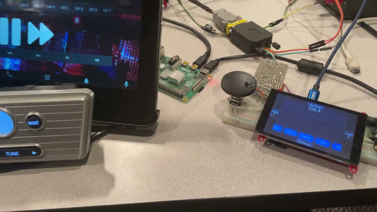
I need to hook up some buttons & knobs and a couple more pins for a CAN transceiver! I would love to get my hands on one of these to make a bigger screen for one of the things I made at work to control one of our radios. See attached video.
(Eagle-eyed viewers will notice the Adafruit Zippy scroll wheel PCB, hidden underneath it is the ATtiny817 seesaw with stemma Qt because that screen only had an I2C and two IOs available, just barely enough for me to hook up CAN and the seesaw)
 north mural
I got an ANO decoder for basically the same purpose except GUI and/or weather related. Yours works awesome. Please share the code, I want to do something similar. I have a touch screen so I can use touchcontrols but those same screens are also in not touchscreen in which an ANO encoder is awesome.
west zinc
subtle lynx
When can I buy if I don't get picked for a giveaway? How many I/Os are left for ...
I’m not setup to sell units. But I’m glad to answer any questions. On this board I think there are four or five leftover pins available.
west zinc
And that's a really cool project.
vernal vigil
Since Jen Schachter is going to be on tonight, here's a book nook diorama I made based on a simplified version of her plans

(and I guess some guy named Adam is going to be on too?)
subtle lynx
north mural
I got an ANO decoder for basically the same purpose except GUI and/or weather re...
it's LVGL, mostly C right now, if that's ok, i can dig that code out and pop it into a github repo. i haven't gotten around to trying to figure out LVGL and CircuitPython together on the esp32 series (or if that's even possible--hence why i want to grab the tablet and try them out together!)
and it's using esp-idf instead of arduino
exotic sierra
vernal vigil
(and I guess some guy named Adam is going to be on too?)
Yeah, no idea who he is
Only famous maker I know of is Jamie Hyneman
🫣
north mural
@exotic sierra don't be savage like that
@subtle lynx thanks, esp-idf is out of my league right now. :/
subtle lynx
i think i have a variant of the LVGL example code that does use arduino, lemme dig around
should be easy enough to plug in the arduino seesaw library then
for the encoder
which screen do you have hooked up?
north mural
planned on using it with circuit python on a project enclosure next to the tft.
3.5" tft featherwing
subtle lynx
ah ok. cool. well, i think there's a micropython port of lvgl, so maybe it can work in circuitpython too
north mural
was going to go with foamyguys tab layouts for displayio but yours seemed like a nice shortcut until you said esp-idf
subtle lynx
should take this to another channel since this is going off topic 
north mural
oops you're right
subtle lynx
which one fits best 
 versed lava
@vivid junco in #help-with-3dprinting wanted a 3d printable grid for the 64x64 panels so I made one... it turned out it was better to do an infill hack so it didn't take a full day to print (2.5 hours instead) but it came out pretty good! Its on my printables with a lot of other adafruit related models if anyone wants to make one! https://www.printables.com/model/252635-adafruit-64x64-led-matrix-grids


 rigid onyx
versed lava
<@841258674353209374> in <#330445847382851587> wanted a 3d printable grid for th...
rigid onyx
versed lava
<@841258674353209374> in <#330445847382851587> wanted a 3d printable grid for th...
wow this looks SICK nice job!!
north mural
Been waiting a month for my brother to show up and we'd build his birthday gift together. Come to find out.... the Macropad doesn't require any soldering. It's all compression fit stuff, plug and play, easy enough for a 10 year old... perfect project for my brother who has no experience with microcontrollers. I posted this in circuit python drinking then realized it should really belong in show and tell. He thinks the Macropad is sick and loved the rotary encoder. His eyes lit up when he realized what it could do and OLED screen helps with the commands per macro. He loves it.


Here's the Macropad YouTube Controller script I wrote for him. He'll get the most use out this one. He loves the Macropad and his cute adafruit lunchbox for storing more adafruit electronics like sensors and boards. 🙂
 short summit
Thanks to foamyguy for both the inspiration and the image and image conversion script, I added a Winamp skin to my Album Art display. I pick an album on my website, and it shoots the art over to the PyPortal and the artist name and album title display in Winamp.
 north mural
ohh nice, good album too.
versed lava
north mural
Been waiting a month for my brother to show up and we'd build his birthday gift ...
I got my nephews all the macropad adabox. It was a fun project for them and I also got to teach them a little about 3d printing
short summit
Macropads are the best!
north mural
my brother is really good with wood working. he'll probably build a wooden box for it. i've seen wooden box designs for them in the learn guides. i'll point him to one of those.
foamyguy's wimpy player is awesome. i might build one of those someday too for a little boombox with a wimpy LCD. Do you have your code for internet album art on github somewhere Paul?
Adafruit has a 20W I2S amp and with 10W speakers could make for a really nice little boombox. 🙂
Though on the product page the 20W amp doesn't have I2S in the title but if you look at the back of the PCB the silkscreen mentions I2S. 😉
short summit
north mural
foamyguy's wimpy player is awesome. i might build one of those someday too for a...
https://github.com/prcutler/circuitpython-programs/tree/main/pyportal - I make no apologies for the code quality, I'm still learning. 🙂
stark latch
Made a 3D-printable version of my H.R. Giger Counter (contains a MightyOhm Geiger counter board). STL files and assembly instructions located here: https://www.printables.com/model/254282-hr-giger-counter
 versed lava
stark latch
Made a 3D-printable version of my H.R. Giger Counter (contains a MightyOhm Geige...
versed lava
stark latch
Made a 3D-printable version of my H.R. Giger Counter (contains a MightyOhm Geige...
Took me a minute 🙂
stark latch
versed lava
Took me a minute 🙂
It all dates back to a friend's tweet about the movie "Prometheus", 10 years ago: https://twitter.com/BadAstronomer/status/213663977069223938
At the time, I bodged together something from bits and pieces: https://www.instructables.com/Giger-Counter/
Now that I've got a reliable 3D printer, I figured it was time to make an actual, printable version with a fancy thumb switch and everything. 🙂

If I ever go to an alien planet, I'm bringing a Giger counter. #ThingsILearnedFomSciFIMovies
 Twitter
·
Twitter
·
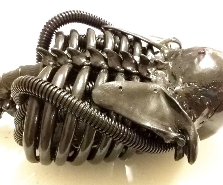
Instructables
Giger Counter: No, that's not a typo. It's a Geiger counter built in the style of H. R. Giger. It started off as a joke a friend posted on Twitter:If I ever go to an alien planet, I'm bringing a Giger counter. #ThingsILearnedFomSciFIMovies...and ended up as a rea…
versed lava
stark latch
It all dates back to a friend's tweet about the movie "Prometheus", 10 years ago...
I love it 🙂 looks like its resin? Threw it a like on printables
stark latch
versed lava
I love it 🙂 looks like its resin? Threw it a like on printables
The original was spliced together from a 1/2-scale plastic skeleton, some split loom conduit, and a bunch of low-temperature thermoplastic, all spray-painted in a color called "carbon mist". I made 3 in total: one that was auctioned off for charity, one for Phil, and one for myself. Not sure if anyone else ever made one from the Instructables thing.
 ember pendant
I upgraded it to usb c. There currently isn't a battery

I had to glue together a proto board and a bakelite board to stabilize the usb board. I then jumped some connections, soldered the original power ports wire to the proto, and soldered the USB pads to the through holes on the proto. This created a simple drop in power module. After cutting the shell, I mounted it. I'm thinking of custom designing the next board and having it printed so it won't be as cobbled together might even sell completed modules as upgrades since drop in upgrades don't seem to exist
 north mural
If it fits it ships. Would be nice if all devices were easily converted to USB-C.
ember pendant
north mural
If it fits it ships. Would be nice if all devices were easily converted to USB-C...
i think most if not all are, so lond as there is room and you have a little know how and such. maybe not phones
grizzled talon
Looking into manufacturing my EYESPI feather-wing breakout. I still have to design a silk-screen (add the pin labels, etc.) for it and adjust a few things. It's coming along well and will be cost effective to manufacture. 👍

 late orbit
I call it MIDIzilla. A custom midi control code footswitch built with a raspberry pi pico w designed for MODEP, an open source emulator for MOD devices.

 north mural
Made a featherwing pogo jig out of a feather tripler.


Eventually I intend on soldering the LORA board on the RP2040's low profile header pins. It's so low profile when they're together you can barely tell they're 2 boards stacked together. Want to test my LORA board without soldering headers on it first, then snipping them off, and soldering it to the RP2040. This seemed like a worthwhile test jig for a low form factor stack. Initial soldering of the spear head pogos, still have to adjust their height in line with the standoffs.
north mural
Also its day 53 of the MagTag on a 2500mah battery running openweather.
 mighty umbra
Working on a web GUI for the Pimoroni Inventor2040w aimed at controlling props and other simple interactive stuff.
 late orbit
Success!
 north mural
at first i was like why is that thing so dirty if it's brand new... took a second to figure it out then i was like ahhh ok that's hot.
late orbit
@north mural are you talking about the graphic i used for the top? Yeah...it's subtle until you see Godzilla. I'm a kid of the 70s so I grew up watching Godzilla during that era. I wanted to find an image from that era but couldn't find anything usable.
 distant frost
This is a simple accessory for the Nike x Acronym Blazer (the grey sideways V screwed to the shoe toward the back). My shoes are size 10.5, and the accessory that I downloaded and printed had the mounting holes in slightly different positions, so it did not work. I made this so that I could tweak the hole positions until they fit. It is kind of like simple stud earrings, I guess.
 versed lava
I also did a 3d printed shoe project this weekend.

 calm badge
late orbit
Success!
calm badge
late orbit
Success!
What is that? Multiple space shuttles control console ?
late orbit
@calm badge nuclear missile launcher. 😀 Actually it's a midi controller.
calm badge
late orbit
<@1004463581464641606> nuclear missile launcher. 😀 Actually it's a midi control...
It's just what I says when I see something with a lot of buttons, but looks very nice. What controller/MCU is handling all these buttons and what's the connector ?
late orbit
@calm badge it uses a Pico W. The connector is a USB cable.
@calm badge here's a pic of the inside.
 calm badge
late orbit
<@1004463581464641606> it uses a Pico W. The connector is a USB cable.
calm badge
late orbit
<@1004463581464641606> it uses a Pico W. The connector is a USB cable.
what is the cable organizer board ? what kind of LCD has such a big backend but such a small frontend?! I have the same LCD backpack but the backplate of that LCD is huge compared to the display on the front?!
late orbit
The board with all the cables is my custom button panel that is to the right of the LCD in the previous pic. I can't remember the exact mfg for the LCD but it's a 4 x 20 LCD.
calm badge
late orbit
The board with all the cables is my custom button panel that is to the right of ...
thanks, I ask all of this because I'm very interested in these kind of enclosure and custom membrane costs too much to print for a custom small project
Wish I could find a motorized switch that stays in a position though that returns to off when powering off
late orbit
@calm badge I just printed mine on an ink jet printer and added lamination.
calm badge
I meant a membrane like this with electronics in them(like resistors and debouncing) and the standard port for membrane. I didn't see one on your panel ?
 late orbit
@calm badge nope, I didn't have anything that fancy.
 patent depot
 torn elbow
ember pendant
I upgraded it to usb c. There currently isn't a battery
torn elbow
ember pendant
I upgraded it to usb c. There currently isn't a battery
I see your USB-C PSP and raise you my USB-C new 3DS XL

 restive forum
torn elbow
I see your USB-C PSP and raise you my USB-C new 3DS XL
restive forum
torn elbow
I see your USB-C PSP and raise you my USB-C new 3DS XL
Pfft... USB-C, USB & GPIO.

 slim finch
All of these mods are so cool! Great work across the board!
north mural
Fits with this years hackaday theme of modernizing old tech. Updating to usb-c counts. Good stuff.
torn elbow
Really makes older/vintage handhelds a lot more useable, charging using your phone charger instead of nintendo's proprietary connector of the year
north mural
Created an easy to use OpenWeather demo for the ESP32 Airlift Featherwing.

the online data will be integrated into my weatherstation project. currently only has offline sensor data from local sensors. will soon integrate online elements into it.
 restive forum
north mural
the online data will be integrated into my weatherstation project. currently onl...
restive forum
north mural
the online data will be integrated into my weatherstation project. currently onl...
I'm working on a portable, online weather monitor.. using a Pico W. 👍
north mural
that would be something very new. haven't seen a lot for the pico w.
restive forum
Having built-in wi-fi is a big plus.. I can use my phone for hotspot, so it's fully portable.
I just have to decide on a method for publishing the data online that doesn't rely on the Pico being active constantly.
north mural
adafruitIO is great for stuff like that. i plan on using adafruitio for logging most of my stuff, i won't be throwing much at it, maybe once every 15 minutes maximum but for most things once an hour is plenty.
restive forum
north mural
adafruitIO is great for stuff like that. i plan on using adafruitio for logging ...
Everything I do must be self-hosted.
restive forum
I'll probably look at some method to dump data into an SQL DB.
 lapis jasper
influxdb has an easy line api for writing data and a built in dashboard too
lapis jasper
up to you 🙂
slim finch
I'm overloading info in an image but most of the informative parts are visible
I have a distribution of air quality sensors across my apartment connected to various ESP32S2 boards running circuit python reporting the values my website, and after looking at the air pressure over time I noticed I could use them to infer the state of some seemingly unrelated parts of the apartment, in this case if the bedroom door is open or closed.
Upper left block of four plots:
Top left of that is the time series of air pressure across three rooms and outdoors (brown is the office, cyan is the bedroom, blue is the living room, and bright green is outdoors). The blue and cyan are just barely visible over each other, with the blue dominating most of it. But I noticed I could see the cyan sometimes but not other times. This happened often enough that I thought it might not be noise or artifacts from matplotlib. I looked into it and took the difference of the two sensors over time. The red plots are two difference plots showing that the pressure difference is blocked into groups but does also wanders a bit over time. The bottom left of the top left block is the histogram of the red plots y values showing two clean structures.
Bottom left block of four are the plots PyMC gives when it fits a model for two normal distributions. Basically it found the values you need for a bayesian classifier.
Righthand three:
the histogram of air pressure differential data, the pdf of the points, and third plot is the probability any air pressure differential value is caused by the 0th cluster, or 1th cluster based on the value.
The intersection of the third plot is how I determine if the door is open or closed. If the differential is below -0.08 hPa I say the door is closed, if it's greater than that I determine that it's open
the whole model is while the hvac is running, and windows are closed. As those change the air pressure across my place the model would stop being valid without those conditions
 north mural
Got some online data going now. Just want to show the inaccuracy of trying to rely on on-board temp sensors. The board voltage/heat does affect them significantly. It's better to use external sensors.
north mural

because the bluefruit sense must be in a featherwing stack its highly susceptible to board heating. the more intensive code you're running, and the hotter the ambient temp gets, the more inaccurate it becomes. it was 10 degrees off yesterday showing 101F when it was actually 91F ambient. so it's only really useful as a CPU temp monitor which is a shame because the onboard pressure sensor is the most accurate of any pressure sensor i've tested.
so it's really best if coupled with an external stemma temp and humidity sensor while keeping the onboard pressure sensor.
 junior barn
north mural
because the bluefruit sense must be in a featherwing stack its highly susceptibl...
junior barn
north mural
because the bluefruit sense must be in a featherwing stack its highly susceptibl...
Using these in several BLE connected UM FeatherS3 temperature projects. Slap a STEMMA connector on them and mount away from the cpu. Works great! https://www.adafruit.com/product/5064

The SHT30-D sensor has an excellent ±2% relative humidity and ±0.5°C accuracy for most uses. Unlike earlier SHT sensors, this sensor has a true I2C ...
signal wigeon
north mural
not even sure what i'm looking at. gps, rtc, 2 displays, antenna board, feather, and a battery that looks like it's about to explode.
 white zenith
versed lava
I also did a 3d printed shoe project this weekend.
white zenith
versed lava
I also did a 3d printed shoe project this weekend.
AWESOME shoes (because I have the same ones and planning to add LEDs, lol)
 balmy lake
For anyone who was watching the CircuitPython day Show And Tell.... we have liftoff 😂
https://twitter.com/gvy_dvpont/status/1560717877098995712?s=20&t=W58CSK7RWWrB9FTf7P-KBQ


Anyways, here's my animatronic Racacoonie.
(H̶̵̶e̶̵̶ ̶̵̶c̶̵̶a̶̵̶n̶̵̶ ̶̵̶c̶̵̶o̶̵̶n̶̵̶t̶̵̶r̶̵̶o̶̵̶l̶̵̶ ̶̵̶m̶̵̶e̶̵̶ I can control him with an app, or by automatic gaze tracking if I'm in front of a camera)
CC: @allatoncemovie @Daniels
Twitter
·
signal wigeon
north mural
not even sure what i'm looking at. gps, rtc, 2 displays, antenna board, feather,...
LOL
Advance GPS tracker with RFpager
battery is ok, just looks weird 😄
north mural
I forgot to show off my shirt at the end for @terse totem and @warped siren on show & tell today.
 versed lava
white zenith
AWESOME shoes (because I have the same ones and planning to add LEDs, lol)
versed lava
white zenith
AWESOME shoes (because I have the same ones and planning to add LEDs, lol)
Nice - I have some other mods I'm planning to do to them (decals mainly). I also got some big gray toestops that look nice
 warped siren
north mural
warped siren
north mural
YES. That is super
versed lava
Playing around with multi-material custom keycaps

 north mural

i showed a bad example during live show and tell of how close the RP2040 board can be mounted to a lora featherwing. this is why i needed the pogo jig. when you solder them together there is no separating them without cutting through the pin headers holding them together. once soldered together it's almost a permanent combination.
 hexed star
Hey guys, I recently created & launched a midpower rocket with active roll control, powered by a flight computer soldered onto perfboard featuring an Adafruit feather M0 among some other sensors!
 white zenith
versed lava
Nice - I have some other mods I'm planning to do to them (decals mainly). I als...
white zenith
versed lava
Nice - I have some other mods I'm planning to do to them (decals mainly). I als...
Id love to see lol! I also got the yellow ones and I'm airbrushing them UV colors (no lights for that pair)
calm badge
i wanted to do rockets once but im not good at math and i was afraid things would go wrong and it would escape earth orbit.
candid crescent
That's a fantastic problem to have in amateur rocketry.
stark latch
I've been working on an OpenSCAD library that's specifically for creating 3D-printable boxes. I've used it for everything from pill organizers to Retro Pi game consoles. It does most of the heavy lifting so all I need to do is tell it what size and what features I want. It's ideally suited for small project enclosures (assuming you need something that's rectilinear). Finally got around to adding the source (plus a few demo files) on github: https://github.com/degroof/ConfigBox Would love to get some feedback.



GitHub
A configurable box in OpenSCAD. Contribute to degroof/ConfigBox development by creating an account on GitHub.
north mural
It's all 3D files so you'll need someone from the 3D crowd to look into it. Neat enclosures.
stark latch
It's incredibly convenient. Yesterday, I decided needed a pill organizer for mid-day (as opposed to morning and evening) pills. So I spec'd out a minimally-sized box that would just barely contain those meds. Got the whole thing done in a couple hours.

 terse totem
north mural
terse totem
north mural
nice!
versed lava
3D printers are amazing. Every once in a while you print something that pays for the printer.
 rugged grove
stark latch
I've been working on an OpenSCAD library that's specifically for creating 3D-pri...
rugged grove
stark latch
I've been working on an OpenSCAD library that's specifically for creating 3D-pri...
I've been wanting to print some boxes but don't know blender yet. This seems like a great solution
Do you mind if I dm you with some questions?
stark latch
rugged grove
Do you mind if I dm you with some questions?
Sure. That's fine.
rugged grove
Appreciate it
north mural
just thought of a neat idea for your project. grid organizational bins like you buy in stores. your scalable code would probably work great for something like that.
versed lava
north mural
just thought of a neat idea for your project. grid organizational bins like you ...
https://www.youtube.com/watch?v=Bd4NnHvTRAY <--- this may be of interest to you 🙂
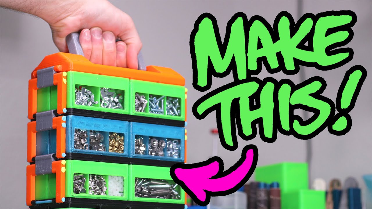
You will be uncomfortably organized!
Use BGCAMZACK to get $5 off the Beagle Cam! https://bit.ly/3yeQq2h
ℹ Watch the first Gridfinity video first! https://www.youtube.com/watch?v=ra_9zU-mnl8
Beagle Cam Amazon links:
🇺🇸 https://amzn.to/3yCQqL7
🇩🇪 https://amzn.to/3uloCsd
🇫🇷 https://amzn.to/3OXFGfr
Thanks to everyone who made awesome Gridfinit...
north mural
Oh i got 2 new organizational bins that I still have to fill with parts. Was just an idea for you to better show off what your scaling code can do.
stark latch
That's an interesting idea. Might be fun to make up a library specifically for storage containers / bins. Stackable / interlocking, etc.
short summit
This is a similar idea: https://www.thingiverse.com/thing:1264391
stark latch
Nice!
 devout verge
I made a candle-shaped controller for Sky: Children of the Light. It’s powered by a QT Py M0, which unfortunately didn’t have enough storage to do it in CircuitPython so I had to rewrite everything in Arduino. An accelerometer is used to detect gestures which correspond with key presses. This is my first time 3D printing a shaped enclosure for electronics, and while it’s far from perfect, it came out better than I had expected.
 hybrid sigil
VSCode users playing with web workflow in CircuitPython 8.0 beta might find this interesting. Still rough, but seems to work well. Warning...only tested on Mac so far but shouldn't be too platform specific. Will do some testing on Windows today...Windows 10 seems to be fine, too.
https://github.com/ae5au/vscode-circuitpython-webupload

GitHub
VS Code Task to upload to CircuitPython board via web workflow - GitHub - ae5au/vscode-circuitpython-webupload: VS Code Task to upload to CircuitPython board via web workflow
short summit
That's really cool
hybrid sigil
short summit
That's really cool
Thanks Paul! Also, thanks for the work on the podcast. I'm enjoying it!
short summit
thanks!


 north mural
compared to a large powerful laptop that's a nice cheap compact war driving setup. needs moar cyber punk aesthetic 🙂
versed lava
 grave owl
Doing styrene mockups of pi400 frames.
grave owl
Doing styrene mockups of pi400 frames.
Oh man, now I want to design and print a rig to mount my field monitor like that
grave owl
north mural
compared to a large powerful laptop that's a nice cheap compact war driving setu...
And honestly cloud computing and or simply connecting to a machine at-home means anything is possible from this. If your computing power is elsewhere, and accessible there's not really anything this keyboard can't do.
grave owl
versed lava
Oh man, now I want to design and print a rig to mount my field monitor like that
Do it
 stark latch
I made this because Shelby (cat) is always trying to convince one of us that the other hasn't given her the treats due her. Verb on left, past participle on right, noun on slider.
 candid crescent
stark latch
I made this because Shelby (cat) is always trying to convince one of us that the...
candid crescent
stark latch
I made this because Shelby (cat) is always trying to convince one of us that the...
Clever use of grammar! 👍
versed lava
stark latch
I made this because Shelby (cat) is always trying to convince one of us that the...
Litter Scoopen
 dawn bane
made a rpi based handheld with gps, rp2040 for USB keyboard with BBQ10


RC3 will fix OLED small screen for system status, jog dial wheel for tab/up/down bash commands


will be fully open source and promoting GIS application and MSX emulations
versed lava
dawn bane
will be fully open source and promoting GIS application and MSX emulations
Where do you purchase these keyboards?
short summit
versed lava
Where do you purchase these keyboards?
I think it's the one by Solder Party: https://www.tindie.com/stores/arturo182/
north mural
Those are sweet!
short summit
Or mabye not, I'm not sure now that I look closer
dawn bane
Keyboards from Shenzhen... dismantlement from bbq10...
versed lava
short summit
I think it's the one by Solder Party: https://www.tindie.com/stores/arturo182/
Thanks! Even if its not the same one keyboards like that were sold out everywhere last time I looked
 marble mantle
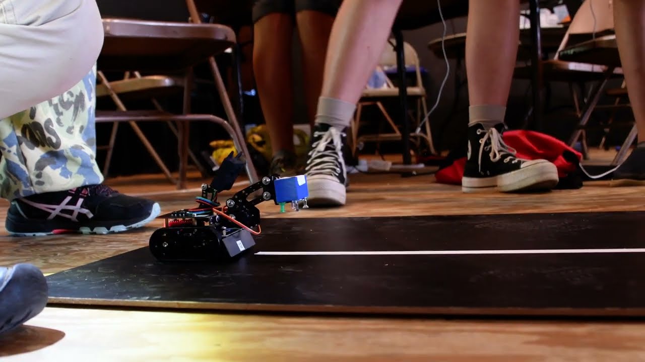
robots I built used by kids in a robotics class in summer camp:
https://youtu.be/jOU6kb7Fh8Q
 uneven dove
OK I feel close to being at the next step.
I have learned that you can't really reverse engineer from brd, but you can from sch.
I learned that Kicad libraries are not as easy to find compared to Eagle.
I learned that this was not hard, but there were a lot of steps that could not be skipped.
I almost figured out how to edit footprints and or symbols, but according to an error that I chose to approve, it didn't happen yet.
I may be ready to have a board made now. Not sure if this is where I can ask for recommendations? I assume the difference is the price/time/location difference? So someone in the US?

 exotic sierra
uneven dove
OK I feel close to being at the next step.
I have learned that you can't really ...
exotic sierra
uneven dove
OK I feel close to being at the next step.
I have learned that you can't really ...
#help-with-hw-design is a great place to get feedback on your designs
uneven dove
exotic sierra
<#656770973852237844> is a great place to get feedback on your designs
Thanks!
 solar yew
The Most Useless Robot Ever.
https://youtu.be/uhePhkDf_IQ

Github Link:
https://github.com/shoniecaplan/UselessRobot
#arduino #electronics #arduinoproject
haha
 brave socket
https://github.com/zax71/EC-Online I made a Minecraft server player counter, this displays the current online player count on an LED bar graph and automatically turns off the display between 9PM and 9AM so you can sleep at night💤. I used MicroPython so it worked with the Pico W (or maybe move it to an ESP8266 in the future as I have a few lying around and Pico w boards are like gold dust 😆 ).
GitHub
Contribute to zax71/EC-Online development by creating an account on GitHub.
hexed star
Coming soon 👀

 north mural
via constellation art. i see you. nice one.
hexed star
Finished designing my DIY reflow hotplate


 uneven dove
we need better remote power. For aesthetics... batteries yes, but when they need charged it's not wireless anymore. Maybe batteries can plug in and part of the case design to pull one easy and swap another? (like non wired constellations)
 stray orchid
uneven dove
we need better remote power. For aesthetics... batteries yes, but when they nee...
uneven dove
stray orchid
uneven dove
we need better remote power. For aesthetics... batteries yes, but when they nee...
uneven dove
@stray orchid spam?
Anyway my thought was similar to how cordless tools have easy changing batteries...
Today's presents... 4 pages.
UPS can treat my package anyway they want, but we have the power of bubble wrap!
 stray orchid
uneven dove
<@227522092843663372> spam?
stray orchid
uneven dove
<@227522092843663372> spam?
Nope. That device does what you were saying. Instead of charging it, the entire back is the battery, which you can just pop off and stick another one in. There's a supercap that saves the system state while you do, so that it doesn't have to reboot.
uneven dove
Ok.
I figured like power tools. I wasn't even thinking about keeping it running, just the annoyance of so many devices and so many batteries. The little PH connections are going to break eventually etc.
Laptops have quick changing batteries...
Cordless power tools.
Basically what I mean is there are some they are all proprietary. No standardization. Yet.
stray orchid
Well, not for lithium, anyway. Alkaline and lead acid, you've got all sorts of standard options.
uneven dove
yup
that ph connector is standard
I guess its in the author of the housing. I was just thinking of smoke detectors and little star shaped led things on the ceiling being hard to change batteries in, but also wires on the ceiling...
I was just trying to imagine a solution.
I was even trying to imagine crawling in the attic above or wherever and laying down those big charging coils, but there is a half inch of sheetrock usually and that is a huge gap for charging. It might still work though. idk lol
I recently bought this though so I can test some distances.
https://www.adafruit.com/product/1407

The squarish board with two chips on it is the transmitter (power with 9V). The longer board is the output and you can connect that to the part of your project that needs ...
 dim saddle
^ running arduino (via platform.io) and protomatter stack for most of the graphical stuff. I've got it doing a fair bit behind the scenes, hence the blocking pauses every so often. Those things on top are an IR receiver/sender and an I2C temperature sensor. I've also got an RTC attached in behind and an SD Card reader I'm not doing much with yet. It's also reporting sensor data to home assistant via MQTT and soon will likely also add reporting via the same.
Definitely had to do the fun pin remapping thing in SERCOM for the Matrix Portal to wedge all that in.
dim saddle
woo, and just got the IR switching "pages". Now I just need to get it to unload memory a bit on page switches.
 serene juniper
Hi everyone! Thought I’d share another prop project. Used a CPX, all coded in MakeCode. Still needed a lot of tinkering but I think I’m improving
dim saddle
 restive forum
dim saddle
restive forum
dim saddle
Very like! 👍
dim saddle
restive forum
Very like! 👍
It's fun seeing what I can pull off with only 64x64 and 6bits.
restive forum
I'd love to have one myself, but money. 😔
dim saddle
fair
restive forum
I'm still waiting on parts/budget for my pocket weather monitor.
dim saddle
ooh that sounds cool
restive forum
It's getting there.. I just need a few more parts. 😁👍
north mural
have a schematic and board designed for a 16 step sequencer. been staring at it for a while with joy. i've wanted to do something like this for about 20 years and never knew how until recently. i want to thank Lady Ada, Liz Clark, John Park, Tod Kurt, and Skerr. each had their own little thing to contribute over the years that sparked something inside me to learn this stuff. based on the picostepseq by Tod Kurt but having that as a base alone isn't enough if you don't understand how to modify and expand it. i'm finally starting to understand pcb design. this is an add-on board for the RP Pico and according to Adafruit, drop-in boards for the Pico specifically are going to be called Bells. still don't have a name for the board, suggestions welcome.

 stark latch
Me attempting to solve a maze of my own creation...
https://www.youtube.com/watch?v=xU9ZKYrEIkw

A clip of me attempting to solve a multi-tier maze of my own creation. It's either a lot of fun or slightly evil. So hard to tell the difference.
Either way, I'm not very good at it, apparently. Had to mute the audio because it got a bit sweary on the second level.
Not sure what happened on the drop to the second level. Looks like it partiall...
vernal vigil
stark latch
Me attempting to solve a maze of my own creation...
https://www.youtube.com/watc...
A metaphor for life.
vernal vigil
north mural
have a schematic and board designed for a 16 step sequencer. been staring at it ...
I recently learned how to design my own PCBs. It seemed like a big hurdle, and it sort of was, but once I figured out how to make something resembling a "proper" PCB it really enabled me to take my projects to the next level.
(although right now I'm working on something for an adafruit Perma-Proto board)
 vivid junco
Hey all, been working on this project for a few months now and wanted to share my progress. I finally built a wooden frame for it and am fairly happy with the code.
A little about the project:
Essentially it's a glorified clock which displays current weather information (So I don't need to ever go outside again)
The clouds displayed are based on cloudiness, they move based on wind speed, the sun and moon rise and set based on time and local sunset time, the moon phases are accurate to the current moon phase and if it's raining, little rain droplets will fall from the top based on the amount of rain.
Aside from weather, it also displays current crypto prices on the main screen because I'm one of those types of people...
It also has other modes that I can easily switch to using http requests from shortcuts on my phone.
The two other modes I've included videos of are a variation on Conways game of life (I adjusted the rules so it's constantly unstable and think it looks cool) and an animated heart so my girlfriend doesn't get annoyed at how much time I spend on this thing 😅
It can also play a game of classic snake (controlled from my phone) and cycle through around 30 animated gifs that I stole online.
Although this is a project I'm constantly working on, I'd love some feedback from you guys and to hear ideas on different modes I can add
Huge thanks to everyone in this community who has helped answer my noob questions over the last 3-4 months, I appreciate how quick and helpful the responses were. 🙏

 sleek slate
I wanted to let folks know about a new open-source project I released recently: https://k3n.cc/0 . This is a collection of O(all) the not-for-Google software I've written over the last decade or so. Security-first Linux server & container management, various user-space tools, home-security system, smart-home controller, lots more. My gift back to the technical community. **But of special interest to Circuit Python folks might be this: ** https://github.com/kstillson/ktools/blob/main/pylib/kcore/neo.py . It's a Neopixel abstraction layer that provides the same API on circ-py, rasp-pi, and normal CPython (where the pixels are graphically simulated). So you can develop and test code on a full server (with debugging, source control, etc), and upload it to circ-py only when it's mostly done. There's a similar abstraction for more general GPIO pin usage. Would be great if you could check it out and let me know what you think!

GitHub
A collection of Linux tools and notes on their design philosophy - ktools/neo.py at main · kstillson/ktools
grave owl


More pico-duck "cases"
Thick acrylic flexes enough for bootselect to be pressed.
Thin*
 woven flax
Hey guys, I developed a simple RTC & Thermometer using the DS3231 RTC. I love CircuitPython, makes development so much easier & fun! https://youtu.be/gBofy7MMdIY
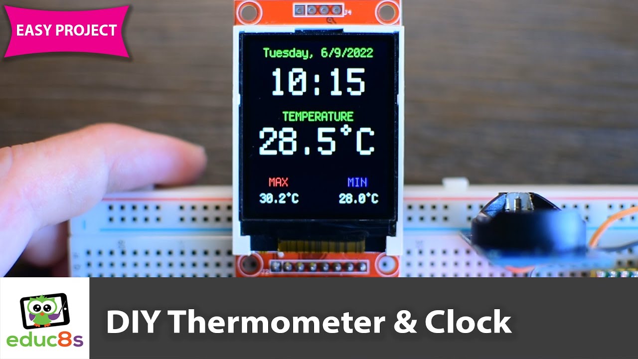
Raspberry Pi Pico Thermometer & Clock using CircuitPython
In this Raspberry Pi Pico tutorial we are going see how to build this low-cost real-time clock and thermometer with a color TFT display using CircuitPython on a Raspberry Pi Pico board.
🛒 Display: http://educ8s.tv/part/7735
🛒 Raspberry Pi Pico: http://educ8s.tv/part/RaspberryPiPico
🛒 R...
@vivid juncoYou have done a great job! Really impressive project. What display are you using?
north mural
@woven flax 1 tiny unnecessary step. the terminalio font is built into circuitpython. it's the only built-in font and you can call it with font = terminalio.FONT excellent easy to follow video. 👍
 solar wadi
north mural
<@619951916746539021> 1 tiny unnecessary step. the terminalio font is built into...
solar wadi
north mural
<@619951916746539021> 1 tiny unnecessary step. the terminalio font is built into...
terminalio.FONT doesn't even include the ° symbol, it's fine as a default for most text, but it's not a universal solution
north mural
he imported terminalio font into /fonts. as far as i know it's the same font...
solar wadi
it's not at all quite the same
north mural
didn't know that, i take it back then.
solar wadi
the builtin font is stripped of most characters that are not low ascii unless they are used by the localization
it is a much bigger font in total than what is included in the binary
but since letters numbers and punctuation at least are there, it's good enough
but no ° 😦
 normal inlet
I finally finished the Gemma Hoop Earrings! (I know it’s a small project and just following a tutorial but it’s been super fun to wear around campus.) https://www.tiktok.com/t/ZTR5Bf4WA/
 brave socket
from machine import Pin

pin_state = [0, 0, 0, 0, 0, 0, 0, 0]

def shift_update(input_data, data, clock, latch):
    global pin_state

    # define the list forwards and backwards
    pin_state = input_data
    reversed_pin_state = list(reversed(pin_state))

    #put latch down to start data sending
    clock.value(0)
    latch.value(0)
    clock.value(1)

    #load data in reverse order
    for i in reversed_pin_state:
        clock.value(0)
        data.value(i)
        clock.value(1)

    #put latch up to store data on register
    clock.value(0)
    latch.value(1)
    clock.value(1)

def set_pin(pin, value, data, clock, latch):
    global pin_state
    pin_state[pin] = value
    shift_update(pin_state, data, clock, latch)
Just wrote a more user friendly version of the code in https://peppe8o.com/how-to-use-74hc595-shift-register-with-raspberry-pi-pico-and-micropython/ in case anyone wants a driver for the 74hc595 shift register
|| It's MicroPython because it's for a Pico W project btw ||
 grand turtle
made a magnetic angle sensor breakout board. In the process of prototyping for a brushless DC motor haptic knob
 hexed star
Figuring out the packaging for my flight computer PCB. Printing the top to this now 🙂

Unboxing it will be like unboxing an iphone lol
exotic sierra
Nice
hexed star

 vivid junco
woven flax
<@841258674353209374>You have done a great job! Really impressive project. What ...
vivid junco
woven flax
<@841258674353209374>You have done a great job! Really impressive project. What ...
Cheers! Appreciate it 🙂 It's the 64x64 3mm pitch led matrix with a raspberry pi 4 and bonnet
round zodiac
ESP32-S3 TFT Feather on battery power running a CircuitPython 8.0 clock, set by Internet time NTP. Open Source, of course: http://chromakinetics.com/esp32/
CircuitPython is now automatically connected to WiFi, asuming you have created an .env file with your WiFi connection info.
Thanks to @solar wadi for help getting this running (in #help-with-circuitpython ) and @terse totem for most of the code from his Parsec video.
 north mural
@round zodiac Nice code! super slim and neat. 👍
 long hound
ESP32 TTGO allowing you to monitor the prices of multiple stocks at the same time. It uses the free finnhub api to grab pricing info: https://github.com/mike-rankin/TTGO_Stocks_Monitor


GitHub
Simple way to monitor stocks using the TTGO board. Contribute to mike-rankin/TTGO_Stocks_Monitor development by creating an account on GitHub.
hexed star
I'm back 😎


Here are some screenshots from the web platform I created to allow users to explore the data from off of the flight computer pcb I'll be selling
In these screenshots the data was being directly read off of the FRAM and transmitted over serial to a connected computer where it was then displayed within the website
Pretty cool
north mural
That's amazing. Does is have a way to compare flights?
Looks gorgeous! Beautiful UI design!
love the font you went with too, no idea what it is but great choice. everything looks top notch from the board design to the web platform. congrats!
hexed star
north mural
That's amazing. Does is have a way to compare flights?
Yeah I'm planning to allow users to upload their flights to the cloud so they can view all of them from one place
Since the board itself can only store 1 flight of data
hexed star
north mural
love the font you went with too, no idea what it is but great choice. everything...
Thanks for the feedback! Not too bad for my first pcb haha
The discord for /r/rocketry tore my product apart lol
But in the end it still was good feedback as well
stark latch
NeoPixel module for a WIP. A Feather, LiPo and NeoPixel Jewel, all crammed into a 3D-printed enclosure. Touchpads on the side control pixel pattern and brightness.

Video demo: https://www.youtube.com/watch?v=484KQ1Va2YY

This module is part of a WIP. The module consists of:
- a 3D-printed enclosure
- a NeoPixel Jewel
- a Feather 328p
- a 100mAh LiPo
- 5 wires
...and that's it. Three of the wires connect the Feather to the Jewel. The other two serve as capacitive touchpads for controlling the module (they're connected to the Feather, and wrapped around posts on t...
long hound
I ❤️anything blinky.
stark latch
The idea is to make something that can be put inside a container with a cutout design. Here's a test piece I just printed, with the module inside.

 floral flicker
My latest silly project 🙂 Adafruit Inside!
I used the 1.69" 280x240 Round Rectangle Color IPS TFT Display (ST7789) and the MAX98357A I2S 3W Class D Amp.
https://youtu.be/KxgmwC9LNg8

I converted the truly dreadful Tiger / Grandstand After Burner Tabletop game from 1989 to play the full original Sega arcade version, including a functioning throttle and 'danger' & 'lock on' lamps.
Check out my pre-project trailer video for the conversion: https://youtu.be/SRIOK9wJTZA
Some good & fun videos reviewing the original version can ...
hexed star
For anyone interested, I've now added the ability for users to upload flights from their flight computer to the cloud & share them with others https://connect.proxima-aero.space/cloud


The one flight on here was actual sensor data uploaded from the flight computer through the site, just not flight data (yet)
Still need to add user auth of course, but one step at a time
woven flax
Hello guys, I created a tutorial on how to install CircuitPython on a Lilygo ESP32-S2 board which is quite fast and capable. https://youtu.be/Sd-uIebrfUs

The Lilygo ESP32 S2 board can run CircuitPython. In this video I am going to show you how to install CircuitPython on the inexpensive and very popular Lilygo ESP32 S2 board. The procedure is not difficult if you know what you have to do, and it won’t take us more than 10 minutes. Let’s start.
🛒 Board: http://educ8s.tv/part/esp32s2
💻 CH340 Driv...
woven flax
I hope you find it useful and that it will save you some time.
 sturdy sierra
Finished my first prop project (Warehouse 13 Tesla) thanks to Adafruit! CircuitPython and all the tutorials on their site are the only things that got me through this. I used a Raspberry Pi Pico and lots of LEDs.
https://hackaday.io/project/184727-warehouse-13-tesla-gun

I have always loved Warehouse 13, and I thought the standard issue tesla gun the agents are given would be a great starting project. I have been playing with programming a Raspberry Pi Pico and an ESP32, so I think I'm ready to get started on a full project.
The main parts will be 3D printed, mostly because I do not have the equipment or skills...
stark latch
I've been playing around with some OpenSCAD code to auto-generate containers based on an arbitrary shape (e.g. from an SVG image). I tried a simple shape first. When that seemed to work OK, I gave it something a bit more complex. As far as I can tell, if I were to give it an image with multiple, unconnected shapes, it'd create a separate container for each. I might have to come up with a way to join up the bottoms in that case, so that it creates a tray of pots.

 vernal vigil
stark latch
I've been playing around with some OpenSCAD code to auto-generate containers bas...
vernal vigil
stark latch
I've been playing around with some OpenSCAD code to auto-generate containers bas...
Is that Lady Ada?
(how does this channel not have a Lady Ada Lovelace emote?)
stark latch
vernal vigil
Is that Lady Ada?
Some random silhouette.
stark latch
This would be Lady Ada, apparently. Also, cookie cutter.

 north mural
@woven flax released another excellent circuit python tutorial today. Super simple to follow along. Great videos. https://youtu.be/RtQqXMeYpqI

In this video I am going to show you how to connect this 2.8” colour TFT display with a Raspberry Pi Pico board. I will also show you how to use it with CircuitPython and I will share with you 3 useful projects to help you get started and save you a lot of time. Let’s start.
This Colour TFT display is one of my favourite displays of all time. I...
stark latch
I put the SCAD code for the SVG-to-container thing here, in case anyone wants to play with it. https://www.printables.com/model/280675-giftbox-keepsake-box-from-image
stark latch
Also, I think I came up with an image-to-cookie-cutter algorithm that creates an outline cutter, plus a press for the details. It works fine, as long as there isn't too much empty space in the interior. I had to doctor this image with a necklace to get it to work.

 compact grove
So if someone is interested in doing a show and tell, what all do they need to do it? ie: how is the video stream imported?
 rough root
compact grove
So if someone is interested in doing a show and tell, what all do they need to d...
rough root
compact grove
So if someone is interested in doing a show and tell, what all do they need to d...
There's a link to a live streaming platform that shows up in #live-broadcast-chat right before the stream time
rough root
Can't wait to see!
stark latch
Think I figured out the whole cookie cutter algorithm thing.

Anybody need an Ada cookie cutter model? Please adhere to the standard safety guidelines when using 3D printed models around food:
- Coat in a food-safe sealant.
- Clean thoroughly, sterilizing whenever possible.
- Do not immerse in clostridium botulinum before applying to cookie dough.
- Avoid using within the core of a nuclear reactor.
There are a bunch more, but I really think they're more common sense than rules. 😄
woven flax
@north mural Thank you very much for the share and the nice words! I am glad that you like and I hope it is helpful!
stark latch
Slight upgrade on my NeoPixel module project. It's now a Feather M0 Basic with a NeoPixel FeatherWing, and a 400mAh LiPo sandwiched between them. Had to alter the capacitive touch code a bit from what I was using on the 328P but otherwise worked out fairly well. USB charging port on one side; touch controls (brightness and pattern) on the other. Runs for about 4-5 hours on a charge.

 prisma sequoia
stark latch
Anybody need an Ada cookie cutter model? Please adhere to the standard safety gu...
prisma sequoia
stark latch
Anybody need an Ada cookie cutter model? Please adhere to the standard safety gu...
Trying to follow step 3. Any recommendations where to get enough clostridium botulinum to immerse it?
 paper charm
Hi everyone, just posting some progress on a board game idea that I'm currently working on. This isn't anything crazy, just wireless communication between devices using MQTT to play and pause music. It was meant as a communications test to see how to pass data around.
 runic axle
Her due date was the 256th day of the year (though she joined us a day late) and I thought those here might appreciate the same namesake...
Meet Ada Silver
 exotic sierra
runic axle
Her due date was the 256th day of the year (though she joined us a day late) and...
exotic sierra
runic axle
Her due date was the 256th day of the year (though she joined us a day late) and...
Your greatest maker journey has started 🙂
 vague spruce
I made this little wand/holder for the induction loop. Parts used:
- Small Inductive Coil https://www.adafruit.com/product/5140
- Miniboost 5v https://www.adafruit.com/product/4654
- 2 x AA Battery Holder
- nOOds - Flexible LED Filament - 3V 300mm long - Pink
- 220 ohm resistor
- 3d printed holder
 paper charm
@cedar trellis slowly making progress. Figured I'd share. This is me testing the matrix idea that you suggested and it works perfectly
 cedar trellis
paper charm
<@196904073255976961> slowly making progress. Figured I'd share. This is me test...
cedar trellis
paper charm
<@196904073255976961> slowly making progress. Figured I'd share. This is me test...
Congratz, this is awesome!
 hazy walrus
Hi all! I made a little self-serve tarot machine and wrote about the process here: https://zachgoldstein.engineering/posts/mechatarot/mechatarot/
It's a riff on a project from a couple of years back by i_mozy: https://www.hackster.io/i_mozy/automated-tarot-machine-62d035
Adafruit M4 Express inside 🙂
 wise osprey
Here is my Halloween Monster M4sk project with a mask i picked up at walmart.
I split the m4sk so i could use the 100mm jumper cable, this helped with adjusting the eyes.
Then i hot glued the boards and the PIR sensor in place, the battery i used 3m doubled sided tape.
The black tape was used to block out the light from the side of display.
/www.adafruit.com/product/4343
https://www.adafruit.com/product/4350
https://www.adafruit.com/product/1578
PIR sensor from my stock


This 9-pin cable is just about 100mm / 4" long and fitted with JST-SH female connectors on both ends. Compared with chunkier JST-PH these are 1mm pitch instead of 2mm, but ...

Lithium-ion polymer (also known as 'lipo' or 'lipoly') batteries are thin, light, and powerful. The output ranges from 4.2V when completely charged to 3.7V. This battery has ...
 jovial void
Hey everyone! I built a macropad with a custom PCB using the Adafruit KB2040. https://youtu.be/P_oSLBZABGA

This is a 12 key macro keypad with 2 rotary encoders, custom keycaps and under-glow RGB. This board is running KMK firmware on the Adafruit KB2040.
00:00 Intro
01:23 Parts
02:30 Schematic and PCB
05:23 Enclosure Design
06:30 3D Printing
08:20 SMD Soldering
09:20 Firmware
10:56 Assembly
13:23 Final Result
Project links...
 solemn vector
jovial void
Hey everyone! I built a macropad with a custom PCB using the Adafruit KB2040. ht...
solemn vector
jovial void
Hey everyone! I built a macropad with a custom PCB using the Adafruit KB2040. ht...
Really nice! 👏
jovial void
solemn vector
Really nice! 👏
Thanks!
north mural

YouTube subscriber counter originally by Becky Stern. She used a NodeMCU board and Arduino. I recreated it from scratch with an Adafruit Feather ESP32-S2 and Circuit Python. Requires the adafruit_requests library and YouTube API token. Code is on my GitHub. https://github.com/DJDevon3/My_Circuit_Python_Projects/tree/main/Boards/espressif/Adafruit Feather ESP32-S2/7-Segment YouTube Stats
Here’s Becky Sterns original. https://youtu.be/R9F8g4r3MAQ Accomplishes the same thing, but now in Circuit Python.

ESP8266 Arduino project displaying YouTube subscribers across two seven-segment displays. Full tutorial with template and code:
https://www.instructables.com/id/YouTube-Subscriber-Counter-With-ESP8266-V2
NodeMCU board: http://amzn.to/2DwYjGQ
shadow box: http://amzn.to/2BlvXcF
Becky Stern is a maker living in NYC. Making and sharing are her two...
short summit
north mural
Here’s Becky Sterns original. https://youtu.be/R9F8g4r3MAQ Accomplishes the same...
Very cool!
 deep star
My still ongoing fallout based raspberry pi all-in-one pc/terminal

 restive forum
Very nice. 😁👍
uneven dove
V.3 is coming soon...
 compact grove
Woooooooo! New survey-in accuracy record for me. 0.2600m / 10.25in. That's phreaky accurate.
 stark latch
The cross-section is the absolute value of a cosine.
The profile is a sine wave.
The twist is a 360° rotation.
Pretty math.
 north mural
Indeed very pretty.
compact grove
Got the survey-in down to 0.2286m (9 inches) today. Was sooooo upset when I saw it switch to complete. Set the receiver to survey in to 0.1016m (4 inches). I don't expect it to ever get that good, but this way I can see just how far it can get. Course at these accuracies may be time to just capture 24hr of raw data and have a ground station do ephemeris corrections and tell me EXACTLY where the thing is.
 vague spruce
compact grove
Woooooooo! New survey-in accuracy record for me. 0.2600m / 10.25in. That's ph...
vague spruce
compact grove
Woooooooo! New survey-in accuracy record for me. 0.2600m / 10.25in. That's ph...
What are we looking at?
compact grove
A U-Blox ZED-F9P receiver under a mason jar to protect it from rain, while on the monitor portions of U-Center can be seen documenting the status of the survey-in process as the receiver uses multiple measurements, settings, and algorithms to try to figure out more precisely where it is over time. First picture it had been running 30122 seconds and reached 0.2600m Mean 3D StdDev, in the second, it had been running 35605 seconds and reached 0.2286m Mean 3D StdDev.
(10 inches and 9 inches, respectively, for those who prefer imperial measurements)
 honest lark
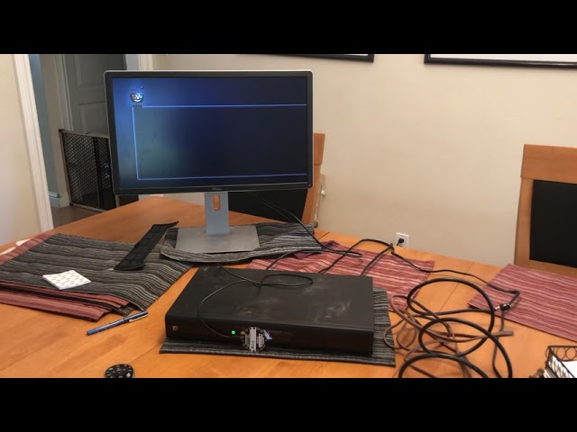
this is what you have to do when you forget the parental control password on your tv box https://youtu.be/quD16blxw3c
 cerulean dirge
I’m excited to get this surface transducer connected to the actual doorbell! This’ll be way more fun than a “donk,” especially for Halloween. :)
north mural
Fixed a feather esp32-s2 that I dropped a solder blob by being a genius and soldering a wire splice while working directly over the feather. First time ever using a hot air rework station. https://www.youtube.com/watch?v=rLR9jsHeNDM
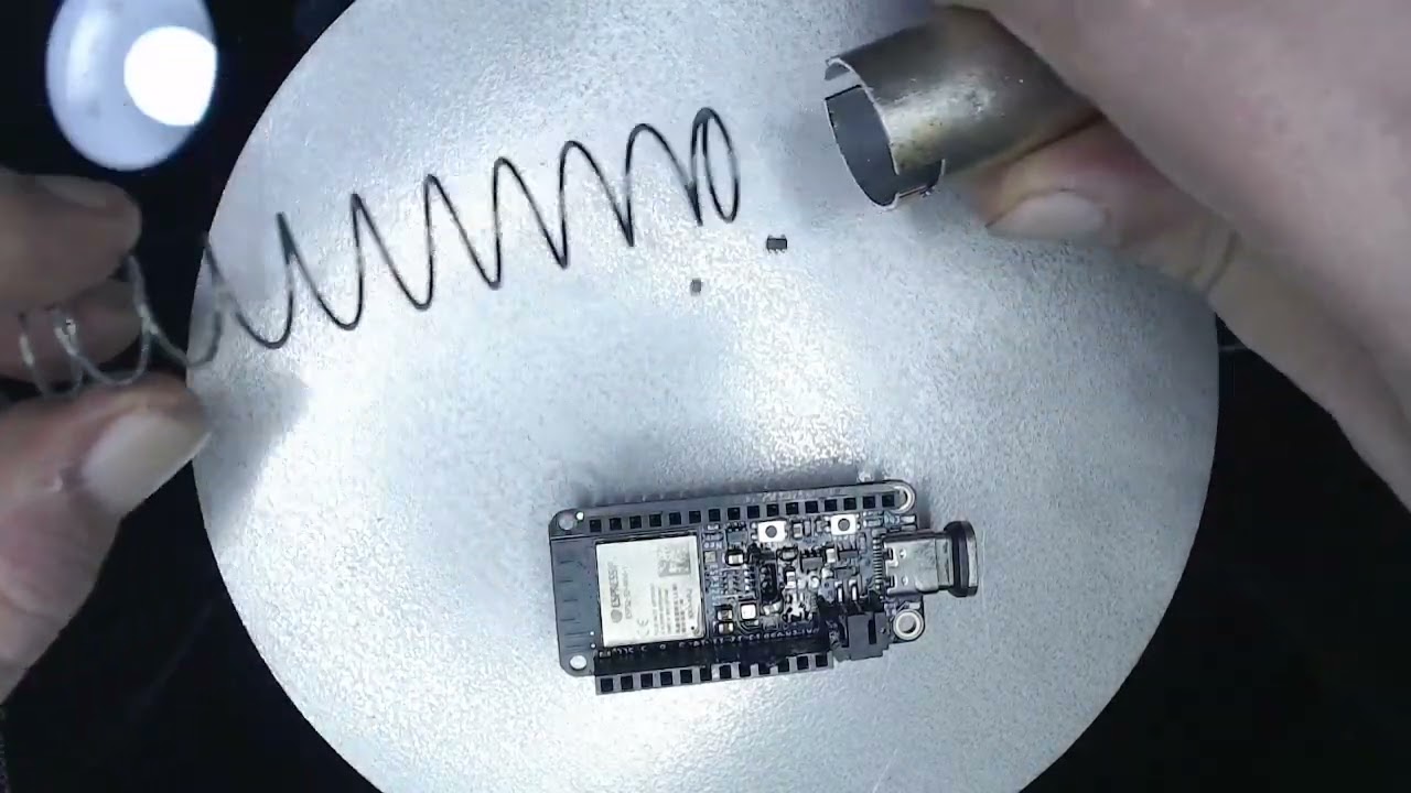
Shows removing SMD component with hot air rework station. ZENY 858D
I did actually turn it on with the solder blob on there. Everything worked except I2C which is what I was using it for. Soldered it back together, turned it on, and it ran code.py correctly first time and I2C works. Success!
compact grove
Sweet, finally managed to read all five sensors detected and data imported. (NAU7802 scale, UBlox ZED-F9R, 3x MPU6050)
really gotta switch to using curses though, man that tearing is harsh.
north mural
Yeah that is not easy on the eye. Congrats on working with the nau7802. Scales sounds like a fun project.
compact grove
I'm doing strongman pull training; the goal being to tackle pulling a 100' (~35m) furrow with an antique and restored 14" single-bottom moldboard walk-behind plow. This whole build is to support the training by giving me a way to not only measure draft forces but build a model that I can throw simulated conditions against and see how far under those conditions that particular pull would have moved the plow.
north mural
Good lord. The scale is capable of measuring how much force?
I think there are different versions that get chunkier the more they can measure?
compact grove
I'm using a 2000kg load cell, so about 20kN (but I need to get a much smaller one... that is suuuuuuuuch overkill for the purpose I'm losing precision).
A 500kg would be ample; my worst case scenario is needing to generate a draft of 990lbf/ft, on a 14" implement, so 1155lbf. That's about 5.2kN.
To give an idea of how beefy (pun not intended but now I have the chuckles) the load cell is

 peak bolt
compact grove
To give an idea of how beefy (pun not intended but now I have the chuckles) the ...
peak bolt
compact grove
To give an idea of how beefy (pun not intended but now I have the chuckles) the ...
Oh look, a new toy I want
compact grove
The hand or the loadcell? o.O :)
peak bolt
Lol the loadcell. But strong hands are good too, I do rope climbing and could always use a spare hand lol
compact grove
The load cell is available on Amazon, search for: walfront load cell 2000kg (not sure if it's cool to post links, if someone can say if it's cool or not I can add a direct link)
exotic sierra
compact grove
The load cell is available on Amazon, search for: walfront load cell 2000kg (no...
Generally fine, just use the shortened link so it isn’t a huge link
The bot will delete messages if you share too many links in a short period of time
compact grove

This PSD load cell sensor is the combination of quality material, exquisite workmanship and high precision. Can be widely in all kinds of weighing environment, such as measuring weight, compression force, tension, especially plays great importance in scaling of hopper etc. Specifications: M...
Sweet, that's the one I have.
vernal vigil
In honour of ladyada and the Feather RP2040, I got some pink patch cables for my modular synth.
 north mural
social media tracker project initialized.
 compact grove
Ooooh, flashy, I like. :)
 forest kernel
Since April I've been trying to revive an old discrete op amp design and adjusting it to fit the 2520/990 standard. I had gotten to the point where I had a circuit board made but I had some issues (it caught fire). I went back to the drawing board and discovered the transistor pinouts did not match what I expected (I picked up a version with the base and collector flipped. Oops) but I was still having massive distortion issues. Today I solved the biggest one


The problem was the matched pair in the lm394h was faulty
With the new transistor


Much lower thd
I still need to make some big adjustments
Mainly matching the transistor pairs in the current mirrors
short summit
You say it caught fire so nonchalantly! 🙂
forest kernel
These things happen
short summit
Nice work!
forest kernel
Thank you
 hardy veldt
End of a long journey but I finally got this thing to work. Basically, I needed to free up my Pi Zero 2 for a timelapse project, but it's currently running my e-paper clock/weather display and the pi shortage isn't gonna end anytime soon.
Well, I had spare KB2040s so I figured, "Can it run this?" It's a waveshare epaper display so it's not readily Circuitpython-compatible (its init is fussy so no displayio), the Python implementation uses PIL, and I don't know C/C++ well enough to dive into Arduino. But someone had ported a smaller display using MicroPython copying its C implementation so I built from that, replaced the RTC and Wifi (also why I wanted to stick to CircuitPython for the module support)... and somehow made it work. It's certainly a touch slower having to send all the pixel data with a weaker processor but it's entirely functional.

Practically used up most of the pins too so I'm really glad this little thing is good enough.
 slim finch
hardy veldt
End of a long journey but I finally got this thing to work. Basically, I needed ...
slim finch
hardy veldt
End of a long journey but I finally got this thing to work. Basically, I needed ...
Well done! I've got a pi0w running my waveshare eink display and I know how finicky that system is, this is awesome to see!
hardy veldt
Thanks! Yeah, the initialization procedure is rather involved (and this particular 7.5in display needs to sleep before every refresh unlike the 2.13in) and I was crossing my fingers for it to work the first time, but thankfully they have a universal driver so it simplifies things by a lot.
north mural
That thing is huge. Looks like progress! Congrats!
woven flax
Hello guys, I posted a new video with instructions on how to use the Nokia 5110 LCD display with the Raspberry Pi Pico board using CircuitPython. I hope you find it useful and that it saves you some time. https://www.youtube.com/watch?v=UNFkMaRvCDk

Raspberry Pi Pico Nokia 5110 ( pcd8544 ) display tutorial using CircuitPython
The Nokia 5110 display is probably my favourite display. I have used it in many Arduino projects in the past and I really like it because it is inexpensive, it costs around $4, it is very easy to use, it has very low power consumption, and it is readable under direct ...
compact grove
You ever been so annoyed at your pile of jumper wires....

... You just jump into TinkerCAD and in less than five minutes hammer out a holder?

and then just casually send it to the printer, not once thinking about how absurd to think of this would have been just ten years ago?
 stark latch
I've designed and printed things to solve lesser annoyances, so, yeah. 😄
 polar crag
Using an eeprom to store data + displaying it on a seven segment

 cyan goblet
Modified light to be time-based. Warm white at night, cool white in the morning. 100% adafruit electronics inside

 dusk zinc
#137 in a series of frivolous network gadgets: Raspberry Pi Pico W + WIZnet Ethernet Hat (and hiding inside: Pimoroni Pico LiPo Power SHIM and battery), running CircuitPython 8 beta. https://gist.github.com/anecdata/75ab1f977782008d33b5b3c6201e6dc1

 subtle delta
I now have the CircuitPythonukiah undergoing an 8 day long test to fully vet it so I can call the project done! Currently using a Linode server to act as a mock time service. I also set up all of the tooling to quickly load the CircuitPython firmware and software so I can get a bunch of these out to friends soon!
 exotic sierra
subtle delta
I now have the CircuitPythonukiah undergoing an 8 day long test to fully vet it ...
exotic sierra
subtle delta
I now have the CircuitPythonukiah undergoing an 8 day long test to fully vet it ...
Very cool! I love it 🙂
Makes me want to make an advent calendar that polls NTP every day to check the day and update the corresponding LED
 lucid bloom
A talking Mac SE, it is set to speak any message it receives using a USB wombat and metro esp32-s2. It is controlled through home assistant using mqtt. My friend set the Mac up to boot to the speech program so it's going to be part of the tour.
https://gist.github.com/matt-desmarais/20e785dca34181b88d8d4f8b32ad5827



Gist
Greeter Mac with custom messages. GitHub Gist: instantly share code, notes, and snippets.
restive forum
👍👍👍
short summit
lucid bloom
A talking Mac SE, it is set to speak any message it receives using a USB wombat ...
That's very cool! I let Anne know, maybe she'll put it in the newsletter. 🙂
lucid bloom
We have been doing some other things with circuitpython and old computers. We are trying to hack old computers so they can be turned on/off through home assistant with circuitpython, hid and mqtt. The plan is to swap the Mac SE metro with a picow
 rugged tartan
compact grove
and then just casually send it to the printer, not once thinking about how absur...
rugged tartan
compact grove
and then just casually send it to the printer, not once thinking about how absur...
I’ve been looking for a high quality 3D printer. Is this one good? On a scale of 1-10. 1 is terrible, 10 is it’s the best one ever. Your feedback would be great
compact grove
I find the saturn to be a solid choice in its size category, especially if you can find it on sale. If the 192mm x 120mm x 220mm meets your volume needs, I would recommend it.
compact grove
rugged tartan
I’ve been looking for a high quality 3D printer. Is this one good? On a scale of...
^
rugged tartan
Thank you 🙏
 fluid belfry
I took an old typewriter from the 80s and turned it into a computer! I made a video of the assembly and a demo of it. There's also a sound test of the custom mechanical keyboard I designed at the end. https://youtu.be/Pd6pa3Jko3w
It uses an Arduino to scan the keyboard and control the typewriter, and the Arduino is connected via serial to a Raspberry Pi with its serial console enabled. This lets me use it as a Linux terminal!
The source code is available here: https://github.com/artillect/serial-typewriter

After lots of work, I've finally finished turning my typewriter from the 80s into a computer. It's a fully functional Linux terminal, and I can use it to do nearly anything that doesn't use a GUI. I go over the design and assembly of the final version of my typewriter, and also test it out! There's a sound test at the end of the video as well, i...

GitHub
Contribute to artillect/serial-typewriter development by creating an account on GitHub.


 dark cairn
djpkg in the works
It actually holds a database and verifies dependencies/conflicts and can handle many packages at once

conpression with jz since no zip/tar support
This is on picow
hardy veldt
hardy veldt
End of a long journey but I finally got this thing to work. Basically, I needed ...
It's rather utilitarian (so I can just glance all the info I need), but I was able to replicate my Zero 2 e-paper clock setup sans gray tones since that used to be handled by dithering via PIL and replicating that process here isn't really worth it.
That said, I had to switch from a KB2040 to an ESP32-S3 feather for raw throughput because it took about 25 seconds for the 2040 to send the data and refresh the screen (understandable since it's 800x480 res. Baseline is 8 for the Zero 2 and it's proportional to the amount of black to display). Now it's 18 seconds with integrated wifi, which is good enough. I'm curious how it would fare with even higher clock speeds so I'm gonna grab a teensy 4 to test eventually.
 compact grove
I can guess some of the meaning of these data but can you walk us through each data point or cluster?
hardy veldt
So the big ones on the left are Hour / Minute. Top right is Day and monthDay. Below that is room temp and humidity via sensor. The final six points are local temp from 12PM to 5PM (upper left to lower right) that's pulled from openweather for the current day (or the next if it's pulled after those hours; the API is a bit strange so I took advantage of it). I decided on those hours since those tend to be the more concerning times of the day especially lately. Data for those gets pulled on startup and every 3 hours.
cunning lava
Today my robot got a proper face.

 stray chasm
cyan goblet
Modified light to be time-based. Warm white at night, cool white in the morning....
stray chasm
cyan goblet
Modified light to be time-based. Warm white at night, cool white in the morning....
Any insights on doing this? I have a similar lamp but I'm unsure how to get it open with minimal damage.
 pseudo olive
Took the Arduino and motor shield out of a Neuromaker hand and replaced with a CP Bluefruit and a PCA9685 servo driver board. Typing selected letters or words into the UART on the iPad makes the hand do the ASL translation. Code to see what ended up working.: (mqtt and bluetooth UART both inop in CP8 for the ESP32S3 currently) https://github.com/BergenMakerspace/NMhand-circuitpython
 subtle delta
I wrote a command line tool to help with writing code in a folder and having it pushed to a CircuitPython device as you save changes. Currently works with Linux and macOS (I think), but hoping to get it working with Windows too: https://github.com/tekktrik/circlink
You can use pip install circlink to download it! Thanks everyone who has worked on circup since it was a big inspiration (and it's actually a requirement since it uses the device detection function it implements).

GitHub
Write code locally and have it pushed to your CircuitPython device - GitHub - tekktrik/circlink: Write code locally and have it pushed to your CircuitPython device
Also, my CircuitPythonukiah project is OSHWA-certified! 
peak bolt
Ooh very nice
 proper valley
This is my TRON Oscilloscope clock using CircuitPython. https://youtu.be/OOFGKmF-wbw https://github.com/LuminousOwl/tron-clock

Oscilloscope clock using Raspberry PI Pico W and AD7302 DAC. The code is in CircuitPython. The font used is TR2N (http://randombell.com/).
Source code is at:
https://github.com/LuminousOwl/tron-clock
GitHub
TRON Oscilloscope Clock. Contribute to LuminousOwl/tron-clock development by creating an account on GitHub.
 fiery basin
My circuit playground board in a made of a milkjug Halloween skull https://youtu.be/S4bFJFoM8eU

 ruby ledge
This video demonstrates something new and novel. Using a resource-constrained 8-bit MCU (Arduino UNO) to decode highly compressed TIFF G4 images directly onto the framebuffer of an e-paper display. I had to trim some functions with #ifdef to make it all fit. The demo images are compressed about 10:1 and need only 1K of RAM to decode and transmit:

code is here: https://github.com/bitbank2/TIFF_G4

GitHub
A set of highly optimized functions for decoding and displaying 1-bpp CCITT G4 images - GitHub - bitbank2/TIFF_G4: A set of highly optimized functions for decoding and displaying 1-bpp CCITT G4 images
 lucid bloom
We are done playing musical metro at the computer museum. We used a metro esp32-s2 with circuitpython to prototype three different computers in the home assistant controlled museum and now we added 2 picows to use with the Mac SE and Performa. The Performa and Gateway have long boot times so using these devices we are able to turn them on at the start of the tour so they will be booted by the time the visitor(s) get to them, then hid sequences are used to make them do things
2. Macintosh Performa: turns on/shuts down and does keyboard/mouse sequences
3. Gateway: turns on/shuts down and does keyboard/mouse sequences using the Metro```
https://youtu.be/nxQLtRhJFW8
https://youtu.be/tHAekMnpw6s
https://youtube.com/shorts/Vy66oe2-2KE?feature=share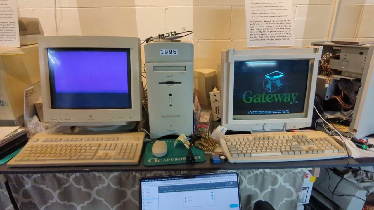
The Performa and Gateway can now be turned on through home assistant using CircuitPython + MQTT + HID
Performa: picow + usb wombat
The performa turns on using HID converted by the usb wombat
Gateway: Metro esp32-s2 + button input + relay
The gateway turns on using a relay

The Performa and Gateway can now be turned on through home assistant using CircuitPython + MQTT + HID
Performa: picow + usb wombat
The performa shuts down using HID converted by the usb wombat
Gateway: Metro esp32-s2 + button input + relay
The gateway shuts down using HID

Mac says quote of the day from Brainy Quote https://www.brainyquote.com/feeds/todays_quote
ruby ledge
Blog post describing what I did above:
https://bitbanksoftware.blogspot.com/2022/10/using-e-paper-displays-on-resource.html

Background In addition to code and power efficiency challenges, I occasionally find other challenges that attract me. Not long ago I started...
 amber flame
I've been working on a Rust driver for the Atwinc1500 and I thought I'd share it here in case anyone would find it useful. Still has a long way to go, but progress is being made. https://github.com/DrewTChrist/atwinc1500-rs

GitHub
A Rust driver for the Atwinc1500. Contribute to DrewTChrist/atwinc1500-rs development by creating an account on GitHub.
hardy veldt
ruby ledge
Blog post describing what I did above:
https://bitbanksoftware.blogspot.com/2022...
Thanks so much for the bit, bytes, and pixels article. Granted I'm rather new to all this but I never truly understood all the masking, division, bytecode, and bitshifting that was going on in the waveshare e-paper code I was piecing together. Now I do and it really is that intuitive when laid out that way.
ruby ledge
hardy veldt
Thanks so much for the bit, bytes, and pixels article. Granted I'm rather new to...
Thanks for sharing your feedback. I appreciate it.
north mural
Full build start to finish of the Adafruit Neopixel Goggles, just in time for Halloween. 🙂 My new YouTube channel for electronics. Will probably end up becoming mostly Adafruit related projects. https://www.youtube.com/watch?v=injS3V2OpEs

Building Adafruit's Neopixel Goggle kit from start to finish. Includes how to update the Trinket M0 bootloader and version of Circuit Python. Project takes about 1-2 hours depending on your soldering skills. This is a soldering heavy project. If your lights don't light up it's most likely due to pin solder touching one of the legs of an LED caus...
sturdy sierra

Adafruit Learning System
Add motion triggered sound and light effects to any prop with Circuit Playground
Just finished a wand from this tutorial. It can do three different colors depending on orientation and fires 3 different IR codes. This is for the laser tag system I'm working on.
 rough root
I love it! Nice work.
short summit
I made a 32x8 NeoPixel matrix audio reactive, borrowing heavily from 2 other Learn Guides
 north mural
That's awesome Paul. I've seen you working on that one. Nice to see it finished!
woven flax
Hello guys, I posted a new video with instructions on how to use the 0.96" Monochrome OLED display with the Raspberry Pi Pico board using CircuitPython. I hope you find it useful and that it saves you some time. https://youtu.be/c64WG4iJuEo

Raspberry Pi Pico OLED ( SSD1306) display tutorial using CircuitPython
In this video I am going to show you how to connect this 1” OLED display with a Raspberry Pi Pico board. I will also show you how to use it with CircuitPython and I will share with you 3 useful projects to help you get started and save you a lot of time. Let’s start.
This O...
north mural
Excellent content Nick!! You setup everything so logically and easy to follow. The image quality is excellent too. Bravo, very well done. 👏
dark cairn

with one 6.1kb installation package, it can install adafruit_hid to the board and the ducky commands.
 peak marlin
After seeing the View-Master Interactive Vision on Retro Tech (12th October), I decided it would make a terrible Pi 4 case 😄
So I made one - it needs work but its a good start for anyone that wants to finish it (my Tinkercad skills are limited)
https://www.thingiverse.com/thing:5574796
 junior agate
@ruby ledge your writeup is great
 coarse edge
I made a thing. https://www.thingiverse.com/thing:5575688

A gadget to add knob input to your computer.
This base and knob are designed to hold an EC11 rotary encoder and a Raspberry Pi Pico.
The EC11 encoder on my print friction fits but you may want to utilize adhesive depending on your printer settings and the fit.
I push the EC11 encoder in fully from the inside and then press fit the knob fully ont...
 grave gust
coarse edge
I made a thing. https://www.thingiverse.com/thing:5575688
grave gust
coarse edge
I made a thing. https://www.thingiverse.com/thing:5575688
This is awesome!
 wintry mauve
I put together a web-based UI for the pico w that lets you control/view digital IO pins over wifi. I just put it on github in case it might be useful to anyone else: https://github.com/justbuchanan/pico_web_control

GitHub
Web interface for controlling raspberry pico w pins - GitHub - justbuchanan/pico_web_control: Web interface for controlling raspberry pico w pins

 surreal dove
finally found a suitable case for the project, a soup case !
https://github.com/redraw/euclid-pico-seq

need to make a video playing it, so you can understand better
surreal dove
peak bolt
surreal dove
That is so very cool
 bitter meteor
https://photos.app.goo.gl/2GLrz1BYakBAhAJv9
I have a lot of time spent with this beautiful thing. I owe a lot of credit to the people who helped me finalize the code and put it all together.
Again thank you for the help with my portal gun. Portal 2 is my favorite game and as the first one is getting an rtx update I figured I should make it and make it as cool (at least to me) as I could. I am 95% done. I need to 3D print some boxes in order to protect the electronics (Propmaker M4 and Featherwing M4) and add the detail wires to the front. In the near future I want to get a speaker so when I press the button it plays the firing sound and when it does the rgb mode it plays caramelldansen

Google Photos
@rough root @frosty topaz
rough root
Oooooooh that's sick! Nice work
north mural
@bitter meteor Glad you got it all figured out. That’s awesome. I was not expecting something of that quality in a first time project. Very impressive.
bitter meteor
north mural
<@263140688919658497> Glad you got it all figured out. That’s awesome. I was not...
Thank you. And thank you for your help
 feral orchid
Not the best magnetic levitator (levitation distance is not far, and the driver circuitry is probably over complicated (with a discrete MOSFET driver ic)), but it's still cool and surprisingly stable (probably because the IFR644, the tc4420, and the LM393 drive the electromagnet very quickly in response to a hall effect sensor change (I was surprised how much of a difference those components made over the original lm358 and 30n06)). It's using one of those cheap 12v electromagnets (which might be why the levitation distance is not very far).

 ruby ledge
New blog post on CO2 and e-paper:
https://bitbanksoftware.blogspot.com/2022/10/the-co2-project.html

The "CO2" Project By Larry Bank Environmental sensing and air quality have always been fascinating to study. I've tested various sensors o...
 lean elbow
Driving 16 noods with the AW9523 LED driver. Impressive results and easy to set up!
north mural
exotic sierra
north mural
Spooky 🙂
 dire mantle
Recently I discover that you can build a working AI assistant connecting to OpenAI via urequests.
If you send yoir HAL in a conversation the bot should build for commands that can be interpeted by micropython REPL.
It looked to me a really interesting apolication for any IoT device
 exotic sierra
Not very showy yet but I’ve started an open source project aimed at being a fairly usable local parts/project management web application

GitHub
Home of local parts management server, MyReels. Contribute to skerr92/my-reels development by creating an account on GitHub.
Runs on a flask web backend with a local database of your parts/projects. I’ve got some low hanging goals for an alpha release
Still a lot to develop but I believe I can get something basic working this weekend
Then hopefully deploy to pypi so it’s pip installable
north mural
More than a few small business makers have been fairly vocal in being interested in something like this. Definitely a void there to fill. 😉
north mural
Gonna call this one done. Featured on digikeys hackapumpkin live stream and everyone was impressed with it. Over the moon happy with how it turned out and the reactions. Yes it’s supposed to be spooky. That’s the whole point. ☠️🎃 https://youtu.be/N6FDmYX_2Bw

Adafruit Feather ESP32-S2 is powering 3 Adafruit 3V Noods tiny LED strips (not EL wire). The candle flicker is coming from a 3W RGB LED powered by an Adafruit M4 Express.
 vernal vigil
got n00ds
 forest kernel
https://www.twitch.tv/magpiepirates
Live music fest featuring members of a circuit bending/diy music community

Full disclosure I'll be playing this using some diy instruments mixed in, but yall should really check out everyone
 shut anchor
Built it 🙂

 sharp bobcat
Fun times using asyncio to make Spooky move this weekend!
https://github.com/flavio-fernandes/spooky-scary-skeleton/blob/main/code.py
https://twitter.com/flaviofdev/status/1587028727065726979 Thanks to you, Adafruit!
Happy Halloween!!!

GitHub
Circuit Python implementation of Kevin McAleer's Spooky Scary Skeleton - spooky-scary-skeleton/code.py at main · flavio-fernandes/spooky-scary-skeleton

Happy #Halloween !!! To celebrate, I printed Spooky and loaded it with @CircuitPython https://t.co/aSEKzIR4sS
Thank you, @kevsmac and @adafruit !
#3D #asyncio
 Twitter
·
Twitter
·
 gilded stag
I made a thing for the WizNet contest, using Circuitpython and adafruit.io https://maker.wiznet.io/DrBrian/contest/tell-me-when-my-room-has-cooled!/
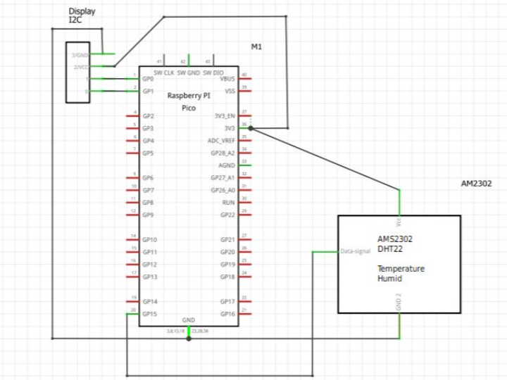
WIZnet Makers
Temperature logging with WizFi360-EVB-Pico, Adafruit.io, with an email action to say the room is cool.
 glad roost
Quickie Halloween deco. Clip art + two Circuit Playground Bluefruits running the “full” CircuitPython animation demo, with some changed colors.
 lean elbow
Recently finished up a project I've been working on for a couple of weeks. The basic idea is a control unit (containing a QT Py M0, an AW9523 LED driver breakout, and an ANO dpad/rotary encoder for input) connected to 5 peripheral units (each with 4 magnetic connectors, 2 contain output from the LED driver, and 2 containing voltage), attached to a magnetic board. You can connect up to 10 LED noodles, all outfitted with magnetic connectors, to any of the peripheral units. For lack of a better idea I used sugru to create handles for attaching/detaching the noodles from the peripherals, and to provide strain relief where the noodles are attached to the magnetic connectors. I'm still programming it, but I'm happy enough with the results already that I couldn't wait to show it off 😄

 north mural

My Halloween mask. There are so many electronics in it I don't know where to begin. 4 green Noods, 1 red nood, 2x 12 pixel rings, 2x GC9A01 round displays. Boards used: Feather ESP32-S2 (6600mah battery), QT Py S2 (2500mah battery), and Gemma M0 (6600mah battery). The mask is pretty heavy and I could only manage to wear it for about 2 hours before my neck became sore from the weight... just enough time to hand out all my candy though so mission accomplished. Had a couple teenagers that were so impressed with it they asked for a photo with me. 🙂 Going to sleep very happy with how my night turned out just handing out candy.
dim saddle
The Pumpkinator MkII: CircuitPython + RP Pico + 3 diffuse NeoPixels on a milled circuit board. Easy code to randomize between 6 or so different shades/levels of brightness for each LED. (Psst @lapis jasper , here's the video).
brave thistle
I just added a repo with an example of a Circuitpython script for the Adafruit ESP32-S2-TFT-Feather board. See: https://github.com/PaulskPt/esp32s2_tft_example

GitHub
Example Circuitpython script for Adafruit ESP32-S2-TFT-Feather - GitHub - PaulskPt/esp32s2_tft_example: Example Circuitpython script for Adafruit ESP32-S2-TFT-Feather
woven flax
Hello guys, I posted a new video with instructions on how to use a 20x4 char LCD display with the Raspberry Pi Pico board using CircuitPython. I hope you find it useful and that it saves you some time. https://youtu.be/ysH_P1WvidQ

Raspberry Pi Pico 20x4 LCD display tutorial using CircuitPython
Dear friends, welcome back! In this video I am going to show you how to connect this big 20x4 Character LCD display to a Raspberry Pi Pico board. I will also show you how to use it with CircuitPython and I will share with you 3 useful projects to help you get started and save you a...
vernal vigil
Here's a digital effects module I made for my synth, getting its input through a nood!
 subtle delta
I've got workspaces, user configuration settings, and documentation/tutorial working for my circlink CLI tool, and pretty much all the bugs (so far) are squashed! It's already been massively helpful for working on code in only one place and just constantly updating a CircuitPython board. A few more nice-to-haves still left, but I think it's time to look at start some of the other CLI tools I want to make! https://github.com/tekktrik/circlink

GitHub
Write code locally and have it pushed to your CircuitPython device - GitHub - tekktrik/circlink: Write code locally and have it pushed to your CircuitPython device
rough root
Printed this vase for my sister
 stark latch
rough root
Printed this vase for my sister
stark latch
rough root
Printed this vase for my sister
That design looks familiar. 🙂
 waxen musk


Printables.com
A kit for making and storing breadboard wires. | Download free 3D printable STL models
rough root
stark latch
That design looks familiar. 🙂
It came out great!
hardy veldt
I kinda wish there was a 1-port stemma breakout adapter that I can cleanly stick to a Feather M4 Express but Sparkfun's 2-port adapter works well enough with some rather tight soldering.
While it's your usual all-in-one environmental sensor pack that uploads to Adafruit IO, I am planning to downscale it to fit in a mint tin using a spare KB2040 and airlift breakout (freeing up the now-stemma'd Feather M4 and airlift featherwing) and replacing the pimoroni envirowing with its relevant sensors; I have no need for the screen and support for it is kinda outdated and it somehow doesn't play nice with the Feather 2040 (even with the updated pin reference in the code, just having it plugged in and unused does something weird to the airlift featherwing and it refuses to connect, which wasn't the case for the other feathers I tried)
 peak bolt
hardy veldt
I kinda wish there was a 1-port stemma breakout adapter that I can cleanly stick...
peak bolt
hardy veldt
I kinda wish there was a 1-port stemma breakout adapter that I can cleanly stick...
Ah, this overlaps with one of my projects. I’ve been tinkering with getting feather m4 express & airlift & pim enviro+ to play nice together. Starting to give up on the pimoroni due to outdated libraries I gotta hack apart to make work, just ordered a bme688 breakout to replace it.
hardy veldt
Ah. Yeah. The three should work but I did use the adafruit Pm25 library instead of the one from Pimoroni and even then there are some fiddly stuff with it since you can't run the particulate sensor at the same time as the wifi. You need the particulate sensor to run first, then take a reading before connecting to wifi.
In that config, you can't really keep it running so I just do a deep sleep every 30 mins to reset the code and take readings that way.
peak bolt
I plan on using an oled featherwing to provide the stemma port for the bme breakout to plug into, but I probably won’t use the screen itself much. So I kinda agree that it would be nice to have a super easy featherwing to tack onto the m4 express to add a stemma
hardy veldt
That was my original idea too. OLED featherwing for the stemma port. XD
But it became increasing clear to me that I don't need the screen at all so I just went with this route instead.
 eternal maple
I made a custom board for that. It fits underneath the feather. A bit tricky to solder, that’s all. https://oshpark.com/shared_projects/56GyOrMq
 hardy veldt
Ah. That's good to know. I'll see if I can get those made and solder them on myself.
peak bolt
Well now isn’t that clever
eternal maple
I just soldered the header signal pins, +3v, GND, and a couple near the Stemma connector.
hardy veldt
Yeah. It pretty much works like a SHIM, which incidentally is something I use for my Pi timelapse rig since that needed a stemma qt port as well.
peak bolt
I’m not very good at tiny soldering like that, so I might have a hard time assembling that, but it might be worth me trying. That link is just for the board and I would need to get the connector separately yes?
eternal maple
eternal maple
I just soldered the header signal pins, +3v, GND, and a couple near the Stemma c...
OSH Park’s 0.8mm PCB works best but takes a bit longer for them to make.
yes, I used this connector: https://www.adafruit.com/product/4208

If you're a DIY enthusiast who likes to micro-manage your project's connections, here is a 10-pack of some micro JST SH connectors! They're solid ...
peak bolt
Nice
north mural
That's a cool idea @eternal maple
 scarlet pelican
This is video from the Electronic Artrium "Vertically Integrated Project" team interactive exhibit at Georgia Tech; mechatronic flowers and video projections and music respond to body gestures: https://youtu.be/gC2FGTFGS2c
Behind the scenes technical details: https://arts.gatech.edu/sites/default/files/images/how_it_works_-_the_electronic_artrium_vip.pdf
At the Ferst Center for the Arts at Georgia Tech, November 1 to 14, 2022: https://www.gatech.edu/event/2022/10/13/raise-your-hand-interactive-environment-open-111-14-5
Electronic ARTrium Vertically Integrated Pr...
(there's links in the description to behind the scene details)
 vagrant flare
Anyone who need custom build services, welcome to dm me https://youtube.com/shorts/uuZ1VMsYWpo?feature=share

It's a bakeneko 60 keyboard, polycarbonate body case with rainblow plated colors stainless steel weight.
We offer keyboard case prototype services with high quality for individual enthusiasts and designers, can be one-off production or run a small batch.
Our factory located in Guangzhou, China, professional in cnc machining, 3d printing and vac...
hardy veldt
hardy veldt
I kinda wish there was a 1-port stemma breakout adapter that I can cleanly stick...
First perfboard project (soldering wires and all) and it turned out pretty well. I really just wanted to use the proto-tin board since I have an Altoids tin, which barely doesn't fit except on the lid side. One unexpected wrinkle is that the particulate sensor doesn't work via UART. This is on me since I assumed it would work (it's a simple breakout and I didn't breadboard test again because the sensor was in use) but everything checks out electronically (signals good and no shorts) after inspection so I would have to suspect it's the controller messing something up since the Feather RP2040 works with it via the featherwing using the Adafruit library.
No matter though. Getting the I2C variant of the sensor. Works out too since that sensor works best with the featherwing and this completely frees me from the Pimoroni libraries that get kind of fiddly to decode.

 naive narwhal
I am an electrical engineer and fashion designing was my pandemic hobby. I just finished my first season of fashion shows and the finale was Austin Fashion Week. I had some other Adafruit items in the show but these shoes were my favorite. I used Betsey Johnson rhinestone combat boots, which had a thick rubber sole. I decided to use a playground express and neopixels. It was programmed to be rainbow until 3G, which it then quickly flashed white. The result was an effect of the flash of light whenever the shoe hits the ground in the walk.
 short summit
naive narwhal
I am an electrical engineer and fashion designing was my pandemic hobby. I just ...
short summit
naive narwhal
I am an electrical engineer and fashion designing was my pandemic hobby. I just ...
That's really cool! Did you use CircuitPython to program it?
naive narwhal
short summit
That's really cool! Did you use CircuitPython to program it?
I have in the past. I used makecode this time. It was my first time using makecode but I do a lot of STEM work and figured I should start using that for items I want to pull into kids project.
The shoes were initially based on the Adafruit Firewalker guide and so I decided to throw in a nod to the guide by also making a “Never Log Off” tshirt. I paired it with this outfit that I made from cutting up a DDR mat. I think I’ll do the DDR one again and actually try and preserve some of its functionality.
 short summit
Awesome, thanks!
peak bolt
Very cool!
stark latch
naive narwhal
I am an electrical engineer and fashion designing was my pandemic hobby. I just ...
Oh, now you have to post video of that, because that sounds amazing.
naive narwhal
stark latch
Oh, now you ***have*** to post video of that, because that sounds amazing.
Sure thing! ☺️
stark latch
naive narwhal
Sure thing! ☺️
Oh, that is amazing!
naive narwhal
stark latch
Oh, that is amazing!
Thank you! 😊
 ancient skiff
neopixel bff text scroller https://github.com/adafruit/Adafruit_Learning_System_Guides/pull/2334 @median spoke

GitHub
PXL_20221115_170323425.TS.mp4
ancient skiff
naive narwhal
Sure thing! ☺️
joining in with another call of "amazing"
 median spoke
ancient skiff
neopixel bff text scroller https://github.com/adafruit/Adafruit_Learning_System_...
median spoke
ancient skiff
neopixel bff text scroller https://github.com/adafruit/Adafruit_Learning_System_...
That looks great. I should update my code to match yours. I think the bitmap font labels weren’t a thing when I first did it.
ancient skiff
It took me a bit of time to realize just how simple it could be. I started out expecting a LOT more code but something really easy fell out of the tree onto my head.
woven flax
Hey guys I posted a new video on how to load animations on an OLED display, color and monochrome. I hope you like it 😉 https://youtu.be/WqyBWcjs_oY
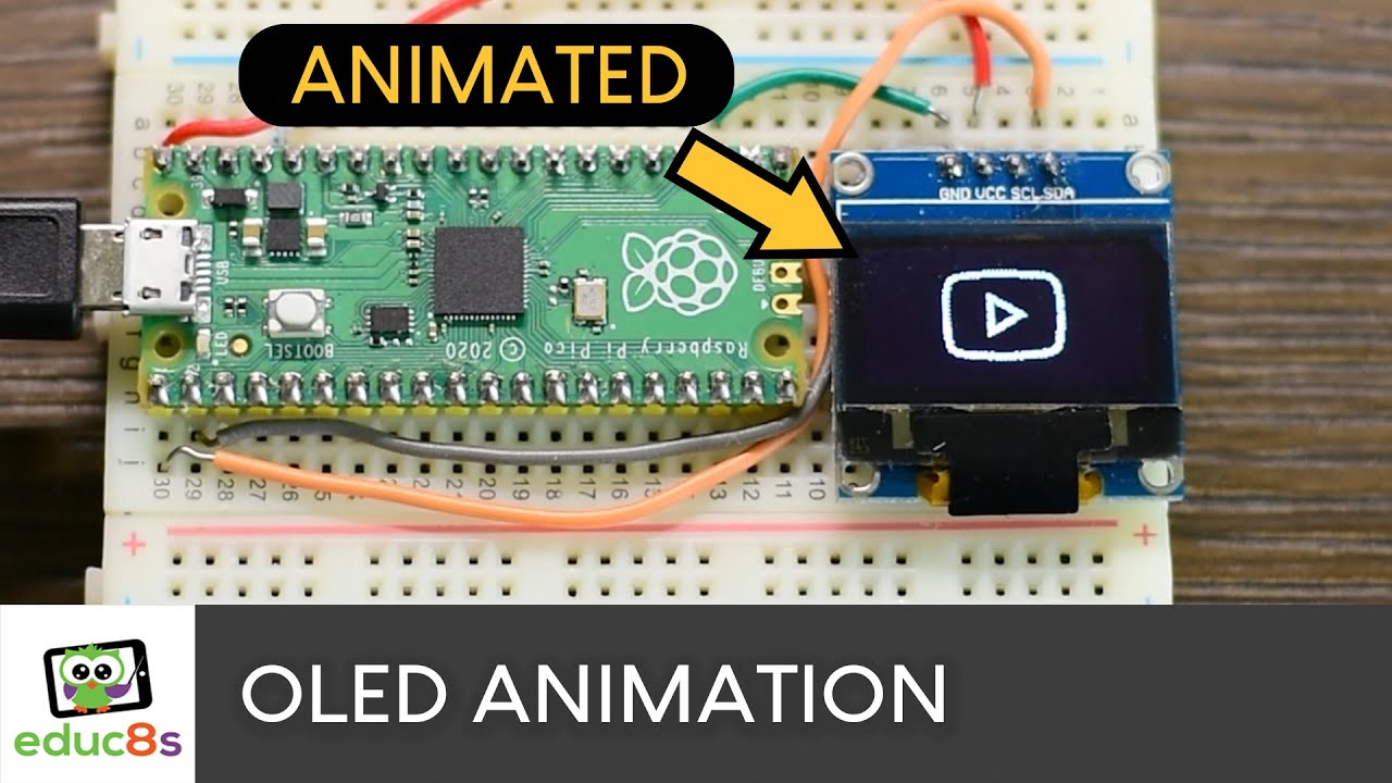
Animations on OLED displays using CIrcuitPython
There are many ways to load and display an animation on an OLED screen, either with Arduino or CircuitPython. I am going to show you what I think is the easiest way to achieve it. I will work with the monochrome OLED, but the procedure works with the Color one as well with only one minor differenc...
 sacred helm
game boy with dot matrix display on atmega328p

 slim finch
Woo! My project (started in Jan, and what I've been heavily working on since late August) is finally working to the stage it does something *For* me.
I want to track my sleep and have my home turn off lights earlier on nights following a night of bad sleep, or flag when I'm sleeping too much and am probably getting depressed. I have the whole pipeline working to the stage where it's able to notice when my partner and I each get up in the morning, and if we've stayed out of bed for a long enough period of time, it'll turn off the blue LED lights we use to help us wake up.
It does this by the placement of three accelerometers on the metal frame of the bed in roughly three of the four corners, and keeping track of the angle they're at. When we get in and out of bed, it'll change some in a step function like way. The sensors are out of the way, and when I get clips printed, the wiring will be controlled so it stays off the floor and the roomba can move beneath it. The whole setup is designed so at no point do we have to change our behavior for the sensors, they're out of sight and mind.
If it's the morning, another program listens for a step change on the correct sensors and correct angle, and turns off the lights for me, making this project finally add something to my home, rather than just sensing and some hope that in the future I'll figure it out.
I got that last piece of the puzzle up and running yesterday, and got to enjoy it working this morning as it turned off the lights behind me.
 short summit
that's really cool! I like how you said you don't have to change your behavior for the sensors
slim finch
That's one of my main focuses with how I'm working on my 'smart' home--I strongly want my home to form around me, and not require me to fit around it. A lot of sleep sensor apps are either watches you wear to sleep or apps on your phone that you place on the bed. That required difference in my behavior wasn't something I wanted to commit to if I could engineer a better solution
peak marlin
When I took my Systems Analysis course back in the 80s, the lecturer said that one of the primary rules for software development was "develop for the way you work, rather than changing your work to fit with the system"
hardy veldt
hardy veldt
It's rather utilitarian (so I can just glance all the info I need), but I was ab...
Update and for those who might consider using a Waveshare 7.5 e-ink display with an iMXRT1062 (via teensy 4.0 and circuitpython): It's blazing fast, even faster than my Zero 2 W benchmark of ~8 secs, granted that's a different implementation. From ~28 seconds/full refresh of the ESP-32-S3 to ~5 seconds on the Teensy 4.0. Caveat is that it's a bit unstable to use as a clock; it crashes and resets on the display's sleep function and iirc, the deep sleep library for the teensy 4 isn't quite stable as well. Regardless, pretty excited for a fully-capable M7 feather/circuitpython implementation when it finally comes.
 scenic siren
slim finch
Woo! My project (started in Jan, and what I've been heavily working on since lat...
scenic siren
slim finch
Woo! My project (started in Jan, and what I've been heavily working on since lat...
Congrats! This is great!
slim finch
scenic siren
Congrats! This is great!
Thank you!
ancient skiff
We went to a potluck and I realized this would be a great way to tell folks what we brought
 solar yew
Here's a quick video showing a BME280 temp., humidity, and pressure sensor (altimeter), along with a VCNL4040 Proximity and light sensor. They're sending MIDI note and CC messages to my DAW and my Behringer ARP2600 synthesizer clone. I envision being able to one day monitor data streams using "music". https://youtu.be/fR1cABqO-cU

I finished up my weather sensor prototype. Honestly, it pretty much built itself thanks to the great sample code from ladyada at Adafruit.com. Her examples were used to glue together a proximity and light sensor with a temperature, pressure, and humidity sensor. I wrote some code to send these values (some of them adjusted to be within valid val...
short summit
solar yew
Here's a quick video showing a BME280 temp., humidity, and pressure sensor (alti...
this is great! Did you use CircuitPython?
solar yew
short summit
this is great! Did you use CircuitPython?
Yes. I have an updated use case for this configuration here: Tune your 3D printer's bed by ear... https://youtube.com/shorts/gxGA1l6Sxvk?feature=share They both use very simple altered example code from the Adafruit website.

 worn wagon
 solar yew
If you need to play around with Arduino, a jigsaw and a soldering iron in your holidays, then here you have some inspiration : https://www.youtube.com/watch?v=LrLCPcfc_rA
Here you can learn how to make / create your own 1:1 Christmas tree with LED effects - use your skills with a jigsaw and a soldering iron and you can enjoy this piece of Christmas decoration.
Links to items in the video:
https://www.freepatternsarea.com/designs/stylized-christmas-xmas-tree-silhouette-vector-art-free/
Links to GitHub folder:
ht...
 tame dawn
Hi! I started working on this project back in June and I finally have it set up and running at my mom's - the project is for her. She's become less tech savvy as she's gotten older and was struggling with using Roku devices and streaming apps. So I built her a 4 button remote using the Matrix Portal 4, 64x32 RGB Matrix, and a 4 key Neokey keyboard. The code is available on Github, along with the 3D printing files (.scad and .stl). I even added the Adafruit logo on the stand, as my way to say thanks.  Sorry for the mismatched filament, I ran out of the turquoise at the very end 😭


GitHub
A simple 4 button remote that will launch specific shows. - GitHub - niccit/easy-remote: A simple 4 button remote that will launch specific shows.
pulsar mortar
Coffee roaster testing
Right now, Ive got the main fan and rotation working. Heater output does work but its not hooked up 😄
Unfortunately, I wont be able to control the speed of the main heater fan because I messed up on the package, so its hooked up to a relay right now. I wanted to be able to control the speed of the heater fan so I can get more or less heat, but I should be able to do that with a PID loop for the heater
 neon mica
Dang if I knew this channel existed I should have taken video of my donated christmas build.
 icy thunder
It's also kinda cool to add LEDs to one's backpack. #CircuitPlayGround
https://hackaday.io/project/187037-brake-light-and-turn-signals-for-backpacks

This project aim to enhance safety on bicycles and scooters. It increases the visibility, advertise braking and signals turns.
 flat owl
I made a cheap "bad" USB using the Raspberry Pi Pico and Adafruit TinyUSB! https://github.com/xslendix/picoduck

GitHub
A cheap Rubber Ducky using a Raspberry Pi Pico running on Lua. - GitHub - xslendix/picoduck: A cheap Rubber Ducky using a Raspberry Pi Pico running on Lua.
stray orchid
Got an Adafruit Step Switch but want the LED in a different color? No worries I will show you how.
Adafruit Step Switch: https://www.adafruit.com/product/5499
4-pin 3mm RGB LED: https://www.aliexpress.us/item/2251832580507733.html
Github Project Page: https://github.com/DJDevon3/My_Circuit_Python_Projects/tree/main/Boards/espressif/Adafruit QT...
Embed worked for me.
 sleek anvil
Emulated a custom instruction set 8 bit computer. Planning to make a small handy pcb so it can be programmed in machine code wherever u go. A fun little toy that will keep ur brain engaged. If anyone is interested to work on it together or has some interesting ideas, plz do let me know 😉✌️

It is currently computing the Fibonacci series upto 255
 hardy veldt
Perma'ed my e-paper display rig. Just had enough space with a 2x13 IDC breakout helper holding up the epaper HAT with 4 pins to spare for the RTC breakout to stemma for the light sensor (so it clears the screen and periodically sleeps in low light) and the temp/humidity sensor.
Prototyped it on a Feather ESP32-S3 and I originally wanted to slim it down to a Qtpy S3 so I could keep the Feather but the PSRAM turned out to be crucial so I went with a TinyS3. This setup also solved a persistent ghosting issue I had with this display which I suspected was to due to resistance going through the jumper wires. Turns out these displays are temperamental when it comes to the input voltage so the more direct the connection, the better.
 woven flax
Hey, I just published a new video on how to use the Color OLED display SSD1331 with CircuitPython. Lovely tiny display. I hope you find it useful. https://youtu.be/TGcLY4kgq2o

Raspberry Pi Pico Color OLED (SSD1331) display tutorial using CircuitPython.
In this video I am going to show you how to connect this 1” Color OLED display to a Raspberry Pi Pico board. I will also show you how to use it with CircuitPython and I will share with you 3 useful projects to help you get started and save you a lot of time.
This Color...
scenic siren
woven flax
Hey, I just published a new video on how to use the Color OLED display SSD1331 w...
I sent it on to our Python on Hardware newsletter author. Thanks for sharing!
north mural
I really like your videos Nick. They're very concise and easy to follow. 👍
woven flax
@scenic siren thanks for that!
@north mural Thank you very much! I am glad you like them!
scenic siren
woven flax
<@330227457296957440> thanks for that!
FYI - if you want to submit your videos yourself, you can email a sentence and link (as you did above), to cpnews(at)adafruit.com to have it added to the newsletter. Newsletter is finalised on Monday afternoons, and goes out Tuesday morning, so keep that in mind for when to expect it to be included based on when you send it. 🙂
 rancid kestrel
The E-Fidget, a work-in-progress haptic feedback fidget!

 hidden stratus
Is going on the live show still a thing? See the instruction says to check for link here but didnt see one tonight. Might have something during the holidays to show. Havent been on in years 😉
short summit
hidden stratus
Is going on the live show still a thing? See the instruction says to check for ...
Yup, sure is! The link is posted in #live-broadcast-chat right before the show starts
 grave bone
rancid kestrel
The E-Fidget, a work-in-progress haptic feedback fidget!
grave bone
rancid kestrel
The E-Fidget, a work-in-progress haptic feedback fidget!
Gorgeous! What software are you using for design, and rendering?
rancid kestrel
grave bone
Gorgeous! What software are you using for design, and rendering?
KiCad for everything! It even has a 3d renderer with (very slow) raytracing, which is how I got that image.
hidden stratus
short summit
Yup, sure is! The link is posted in <#330406870256975873> right before the show...
Thanks Paul. My brain saw live broadcast but registered show and tell channel. Ugh 🙂
 cobalt dove
Chyrosran22 posted his unboxing video of my 3D printed keyboard (with 3D printed switches)! https://youtu.be/MH7r6OsExSY
This is by far the longest and craziest unboxing I've done so far. I present to you, the dazzling AHEK95, a.k.a. the Void Keyboard! This is almost entirely 3D-printed and uses magnetic levitation Hall effect switches. Hope you enjoy the video! :)
Intro by Kyle Carter
Outro by Facundo Cabanne
My keyboard reviews: http://bit.ly/1TbOtft
My switch...
north mural
What in heavens name did you create? That's amazing.
cobalt dove
north mural
What in heavens name did you create? That's amazing.
Yeah it's a pretty sophisticated project 😄
 frosty topaz
cobalt dove
Chyrosran22 posted his unboxing video of my 3D printed keyboard (with 3D printed...
frosty topaz
cobalt dove
Chyrosran22 posted his unboxing video of my 3D printed keyboard (with 3D printed...
Where can I get my own...?
cobalt dove
frosty topaz
Where can I get my own...?
How much you willing to pay? 😁
frosty topaz
That is a fair point. The magnets alone are probably half the price of my current keyboard...
cobalt dove
frosty topaz
That is a fair point. The magnets alone are probably half the price of my curren...
It's like $3.50 worth of magnets. You must have a super cheap keyboard! 😁
frosty topaz
Sorry, I meant the hall effect sensors. Though my Pi keyboard is around that...
cobalt dove
frosty topaz
Sorry, I meant the hall effect sensors. Though my Pi keyboard is around that...
Hall Effect sensors aren't expensive
 supple mortar
updated my filament box sensor to include inductive charging via the inductive coils from Adafruit. https://hackaday.io/project/179663-magtag-filament-box-humidity-sensor

Eink humidity tracker with Adafruit MagTag and Adafruit IO
 unreal mica


 wary atlas
Noice
unreal mica
made it to test the chip, https://ww1.microchip.com/downloads/en/devicedoc/20001952c.pdf
:3
wary atlas
Very nice! I hope when I make boards they look that good :3
rough root
Nice solder work
unreal mica
ty
exotic sierra
Very nicely done!
rough root
I might consider a decoupling cap too
vernal vigil
I can't imagine why it doesn't work 😵💫
 wary atlas
I see black wires going to the red bar on the bottom… are they supposed to be like that?
And I see blue going to red on top and black on the bottom
unreal mica
rough root
I might consider a decoupling cap too
hm?
rough root
Oh I see it
unreal mica
 rough root
Nice and neat
unreal mica
it's mostly just a direct copy of the reference schematic
wary atlas
I should pull up the Pico reference info before I make a clone, lol
vernal vigil
wary atlas
I see black wires going to the red bar on the bottom… are they supposed to be li...
uh oh, do electrons pay attention to the colours?
There were two connection errors, now corrected. Still have problems with signal levels.
wary atlas
vernal vigil
uh oh, do electrons pay attention to the colours?
Electrons do not care about colors, but if you’re using red for positive and black for negative, mixing them up is a problem XD you can use whichever rail for whatever you want, it just makes it easy to get confused if you have red + and black - on one side and opposite on the other side
vernal vigil
I have +12V on the far left (top in this pic), -12V on the far right, and ground rails in between.
wary atlas
Ahh…
 cedar root
I'm working on this GrowBuddies project for plant growers who grow within a grow tent https://growbuddies.readthedocs.io/en/latest/ - in case anyone is interested... Thank you.
ancient skiff
I imagined the satirical life cycle of an “integer division business”, from business plan to eventual acquisition, and used ChatGPT to write out the details. I think it’s a delightful example of what ChatGPT can do when used for entertainment. Thanks to some folks on the Adafruit private slack who provided ideas for prompts.
https://docs.google.com/document/d/1PtwaiNcJlpsLcZ8wAL6vgHvkH1uaebcG9u7mh-x6OEk/edit?usp=sharing
Write a business plan for an Integer Division as a Service company. The key product is a JSON endpoint that computes the quotient and remainder of integers.
There are some real LOLs for me, like when ChatGPT is asked to write more "enterprise-like" code and it explains that this code sample is "more verbose than the previous one".
vagrant flare
Welcome to reach me for prototype services, thanks! https://youtube.com/shorts/1RvIGbtUN3w?feature=share
Beautiful Rainbow Plated Aluminum Keyboard Prototype! This is a unique and colorful way to add a little fun to your keyboard case.
We offer keyboard case prototype services with high quality for individual enthusiasts and designers, can be one-off production or run a small batch.
Our factory located in Guangzhou, China, professional in cnc mac...
exotic sierra
vagrant flare
Welcome to reach me for prototype services, thanks! https://youtube.com/shorts/1...
You should definitely take advantage of the Adafruit jobs board to advertise your services, it would be a better way to reach people seeking that help. Cool keyboard by the way! 🙂
Find maker jobs in 3D and CAD, Art, Design, Education, Embedded Development, Engineering, Fabrication, Marketing and Communications, and Web Development
vagrant flare
Thank you!
 blazing marsh
I finally found THE Adafruit discord! I’m gonna be posting a lot of my projects on here, this is tonight’s project, a simdash for Assetto Corsa utilizing a seedstudio ble sense, Adafruit ST7789, and circuitpython

This is a more fleshed out version of an h pattern indicator I already made before with the ESP32-S3 (UM), the reason I chose the Xiao ble sense for this new version is to be more compact and because the S3 doesn’t really have any good BLE support as of right now in cpy, and I want BLE to make this thing completely wireless and battery powered capable
heres a look at the original verison running on an ILI9341 and ESP32-S3, this was just a simple h pattern indicator, the gui was drawn using display_shapes library, with this new one im making bmp assets and loading them through sd... https://youtu.be/amMpBnceCGo?t=22

Just some test footage of running a little Nord on Assetto Corsa with my new Logitech G29, sorry about the POV camera quality, it's just an ESP32-CAM fisheye lens camera taped onto a hat, it's the widest angle camera I had. The FPS is very low and shoddy on it. The FFB settings I'm using and recommend were calibrated by following this tutorial: ...
timestampped at 22seconds, I show the hpattern indicator in action
my dream is to make a final PCB out of this design and possibly manufacture this to sell as a simracing accessory
because the ST7789 doesnt have touch screen, I'm gonna be making a system tray icon with the python computer side driver script, the system tray app would allow u to configure the display and perhaps adjust what is being displayed on it on a python coded preview display of the screen and allow u to move and resize measurement/telemetry "widgets" and configure what values are being displayed however the end user would like it to
I'd love to get connected with y'all at Adafruit, I spent the whole entire summer playing with ESP32s and XIAOs, made a bunch of random stuff with circuitpython, it's such a fun and fulfilling platform, working at Adafruit would be like my dream job... I love making microcontroller peripheral devices... the reason I started this is to one day make a PCB of one of my projects, order a bunch from JLC PCB, 3D print enclosures on my Creality Ender 3, then setup my own e-commerce shop, selling my little peripheral devices... I wouldn't have gotten the inspiration if it weren't for Adafruit... seriously the learn tutorials on the adafruit website taught me so much... if any Adafruit employees are on this server, thank u for the world you guys opened up to me... wouldn't have been able to materialize all these ideas if it weren't for adafruit.com...
check out my shorts on that youtube channel too... i have a circuitpython bluetooth volume control knob, and a pc hardware performance monitoring screen

Simple project, the next step is to 3D print an enclosure for this. Comment if you guys want the code, then I’ll upload it on GitHub, it’s just a slightly modified version of the Adafruit tutorial for this exact project…

A simple code to monitor PC hardware in real time on an ILI9341 TFT display.
those were the first 2 projects I made this summer... then I started to make more sophisticated stuff
feral orchid


Tesla coil driven by class e single mosfet driver working! I still have to tune it, but it produces a sizeable discharge at ~20W input power (current limited to 1.5A with 15V max voltage). The pixelation is my doing, not the coil's lol. It's also out of focus because I didn't want to leave it running for too long while I try to get the focus adjusted. The scope shows that it might be tuned, but I'll have to compare that signal with the gate signal to know for sure. It's driven at a constant frequency right now, but I'll get feedback working later.
feral orchid
I plugged the second scope channel into the gate (green is gate trace). It seems to be working properly (maybe might need a bigger capacitor for full class E performance because the peak only covers about half of the low signal time). The drain-source voltage peaks to 180V before coming back down, which could make touching any part connected to the drain (screw terminal, pads, heat sink, mosfet) shock you (a bigger resonant capacitor might push the peak down, though. There is some more ringing or noise on the gate, but it doesn’t seem to be affecting anything. Interestingly, when I put my hand close, the waveform completely changes. I don’t have a picture of that though.


It’s still running on a fixed frequency, and when I put my hand near the coil, its resonant frequency and output arc length changes. When I get feedback and automatic start working, the coil should always be running at resonance.
eternal maple
The final test of the KaTV project, a kitten screen saver in a miniature retro television console. The enclosure was entirely hand-made with Dremel and Proxxon tools; no laser cutter. Screen saver was implemented on an Adafruit RP2040 Feather, 2.4" TFT FeatherWing, and CircuitPython. Thanks to @sharp comet for the original kitten screensaver code that was adapted for this multi-cat project. https://youtu.be/5aPtLs6iIHw

The final test of the KaTV project, a kitten screen saver in a miniature retro television console. The enclosure was entirely hand-made with Dremel and Proxxon tools; no laser cutter. Screen saver was implemented on an Adafruit RP2040 Feather, 2.4" TFT FeatherWing, and CircuitPython. Thanks to Foamyguy for the original kitten screensaver code th...
subtle delta
CircuitPythonukiahs are finally happening!
 wary atlas
Do they play a tune?
feral orchid
More development on the coil. I'm able to get these nice discharges with 18V. Draws about 30W.

I also got interruption working.
wary atlas
Bzzzzt
subtle delta
wary atlas
Do they play a tune?
Yes, they do - Maoz Tzur
subtle delta
rough root
I assume they are neopixel based?
Just regular LEDs - I'm using the super bright orange ones in the Adafruit store
wary atlas
Nice!
 near plume
Lovely project!
scarlet pelican
Prototype lasercut controller for the arcade games Defender & Stargate build by one of my Retrofuturistic Hardware Vertically Integrated Project students at Georgia Tech: https://youtu.be/ieQnMNsnwN0

Designed and built by Abhi Venkatesan, a student on my Retrofuturistic Hardware Vertically Integrated Projects team. This is a refinement of an earlier prototype: https://youtu.be/5k7lTFkPqWk
0:00 -- Introduction
0:57 -- Stargate
1:43 -- Design files
1:56 -- Defender
Support this channel via a special purpose donation to the Georgia Tech Found...
 neat lake
https://github.com/tuxpresso/os
Buildroot based temperature controller for espresso machines, targeting Arm Linux.
"Reference implementation" using a Raspberry Pi Zero W and Gaggia Classic Pro.
I'm planning on adding a web UI and making further improvements to do things like reduce integral windup from cold-start.


GitHub
Contribute to tuxpresso/os development by creating an account on GitHub.
Temperature performance
 feral orchid
I got music playing on a Tesla coil! It's not the best sounding musical coil in the world, but the audio is recognizably Crab Rave. Honestly, I was impressed by the audio the first time I turned it on to play music. I thought it would be a lot more distorted.

Bottom is the interrupter circuit. It's just a (counterfeit from a cheap Amazon assortment) LM393 and an optocoupler with a potentiometer and audio input.
rough root
Neaaaaaaaaat
near plume
scarlet pelican
Prototype lasercut controller for the arcade games Defender & Stargate build by ...
Love those big arcade buttons! Immediately turns a simple breadboard tutorial into an enticing game. Nice work!
 hot stump
this isn't a project or anything but I just hand-soldered 0201s

 edgy matrix
Rasbery pi pico with a tft 1.8 disply using the st7735r libery. Trying to make a Vpet but in better collor
dark cairn

Lë çōmῥãχt dé lã fΙåsh de #CircuitPython #Ljinux on Seeed XIAO nRF52840
It's 2 am, the only reasonable time to desolder a 50 pin connector.
 Twitter
·
Twitter
·
Yes I did just desolder the 50 pin connector just to not have a gap
2am is a stramge hour dayo
the rest of this abomination is glue, kapton tape and hot glue
the board is encased in kapton
so it can be yanked out later when I stop liking this stupid idea of mine
wary atlas
That's a weird way to spell "awesome idea"
scarlet pelican
Quick demo of a prototype hybrid digital/analog synthesizer built by a senior design team at Georgia Tech that I advised: https://youtu.be/ZyrEZefb1DE

See the detailed demo: https://youtu.be/fLYMtNXaxKE
Adafruit Grand Central M4 Express, digitally generated waveform, SSI2144 VCF & SSI2164 VCA controlled via PWM
Team: Michael Farren, Christopher Funez, Zach O'Connor, David Young
A more detailed demo: https://youtu.be/fLYMtNXaxKE

Demo video showcasing our capstone design project, a hybrid digital-analog synthesizer. The synth can be controlled by any MIDI-capable device and has programmable filter and envelope parameters.
wary atlas
Ohh, I love it!
scarlet pelican
Here's the GitHub with the software for the synthesizer, including a library they made to increase the PWM rate on the Adafruit Grand Central M4 Express from its default 1.8 kHz rate: https://github.com/mtfarren/synth-control

GitHub
Software for the MIDI-Controlled Hybrid Synthesizer project. - GitHub - mtfarren/synth-control: Software for the MIDI-Controlled Hybrid Synthesizer project.
 manic topaz
Can your space heater render video?

 vocal aurora
140W TDP, wow
And another 75W from the GPU
I've always wondered how much of the electricity stays as "information" and how much is lost as heat
I would assume most is dissipated as heat but from an entropy/thermo standpoint some of it shouldn't go immediately to heat from what I understand
manic topaz
vocal aurora
And another 75W from the GPU
I'm not a engineer or computer scientist however I wouldn't look at it in the same way as we do say a motor. As far as I can tell its mostly just a relationship with the size of the features on the silicon chip (this chip is 32nm but currently we're doing 5nm) and the amount of speed the cpu goes. So for mine its a 32NM chip that runs around 3.2Ghz in boost. These days you can get higher clock speed in a smaller package thus they are more efficient.
manic topaz
manic topaz
I'm not a engineer or computer scientist however I wouldn't look at it in the sa...
also there's 2 of those CPUs, so full tilt its around 280watts to the CPU. The actual GPU almost never uses 75watts. The 1650 is an efficiency beast. 😛
wary atlas
My machine is currently drawing ~350W not doing a lot XD
north mural
Are you running it as an encoding server or just experimenting around?
wary atlas
Me? I experiment with stuff, I just had like a quintillion browser windows open
north mural
No, Poppy. He's using a dual CPU server board for video encoding.
wary atlas
Ah
 vital eagle
I made a sociably reactive lamp using Adafruit IO https://youtu.be/hH3rk7p8itk

A lamp that changes color to match your social media notifications.
You may struggle with this video if you haven't watched the previous two. We configure the WLED and API to show a particular light sequence when we get a notification from a social media channel.
Get your Adafruit IO account here: https://io.adafruit.com/
You can use IFTTT as ...
woven flax
Arduino VS CircuitPython Speed Comparison: https://youtu.be/qym-P4GTdIU

Arduino VS CircuitPython Speed Comparison
CircuitPython Code: https://github.com/educ8s/CircuitPython-Pi-Calculation-Benchmark
Arduino Code: https://github.com/educ8s/Arduino-Pi-Calculation-Benchmark
Join this channel to get access to perks:
https://www.youtube.com/channel/UCxqx59koIGfGRRGeEm5qzjQ/join
wary atlas
Oh wow, I didn't realize there was such a stark difference
frosty topaz
The overhead of interpreting python as needed is fairly significant. Great for prototyping and simple applications, but Arduino and other compiled languages still have their own advantages.
wary atlas
Is there a way to compile Python and load it like Arduino?
lapis jasper
wary atlas
Is there a way to compile Python and load it like Arduino?
Not really. C code has a huge advantage because of the compiler's chance to optimize
wary atlas
Would be super cool if someone figured out a way to optimize and compile Python to be fast like C, but still allow for the super-fast iteration of CP
lapis jasper
Cython is the desktop version of that
wary atlas
Nice. I'll look into that
frosty topaz
lapis jasper
Not really. C code has a huge advantage because of the compiler's chance to opti...
On that note, mpy files are pre compiled python packages, right? Do those exhibit similar performance advantages compared to their py alternatives?
slim finch
I think .mpy files are more about compression than they are about compiling in the way you'd compile c code. Because the files are filled with less data you technically get some speed improvements, but not on the order of c compared to python
lapis jasper
mpy reduces import memory cost because it stores byte code already
there isn't much optimization that happens when the mpy is created though
solar wadi
basically it's the same code that makes the bytecode in the mpy file and the bytecode that's generated when a py file is loaded dynamically, after import there should be no difference
 grand jay
i think MicroPython has a way to compile Python into native code, but CircuitPython doesn't include that
wary atlas
Is there a wishlist for CP features somewhere? I'd love that to be added
exotic sierra
wary atlas
Is there a wishlist for CP features somewhere? I'd love that to be added
File an issue on the GitHub 🙂
feral orchid
vocal aurora
I would assume most is dissipated as heat but from an entropy/thermo standpoint ...
All is dissipated as heat. It does make sense since you can't convert information back into energy like you can with light (light can be converted into electricity for example). Every watt that goes into a computer comes out as heat.
rough root
feral orchid
All is dissipated as heat. It does make sense since you can't convert informatio...
A smidgen comes out as moving air from fans
vocal aurora
feral orchid
All is dissipated as heat. It does make sense since you can't convert informatio...
In the end, yes it’s heat. But if you put something into computer memory isn’t there just a tiny bit of energy that hasn’t turned back into heat yet?
vocal aurora
My mental model for memory/storage here is the analogy of the ball on top of a hill, you expend work (heat) to get it there and it stays there until you disturb (read) it at which point it’s released as heat
cobalt dove
Chyrosran22 posted his full review of my 3D printed analog hall effect keyboard (with 3D printed switches & stabs)! https://youtu.be/iv6Rh8UNWlI
(folks here will appreciate the PCB overview at 16:57 haha)

Skip to 20:18 and 20:41 for typing demonstrations.
Get notified if it becomes available here: https://is.gd/ungfOR
Follow Riskable: https://fosstodon.org/@riskable & https://youtube.com/riskable
Void Switch Github: https://github.com/riskable/void_switch
Keycap Playground: https://github.com/riskable/keycap_playground
This keyboard practically...
feral orchid
vocal aurora
My mental model for memory/storage here is the analogy of the ball on top of a h...
Actually might be true in a way. A capacitor (which is used in RAM and Flash memory) stores energy in an electric field, which can later be turned back into electricity.
grand jay
feral orchid
Actually might be true in a way. A capacitor (which is used in RAM and Flash mem...
in theory, yes. in practice, i’m not aware of any practical schemes to do energy recovery from the capacitance of DRAM cells, etc
(DRAM cells also have nontrivial self-discharge rates, which is why they need to be refreshed)
wary atlas
I don't think there's enough energy stored in DRAM to be recovered before it fades
 wild moss
just an fyi, there was a Microsoft Internet Pro keyboard that had two usb ports on it.. so you could have say a usb mouse plugged into the keyboard and use only one usb for the keyboard
frosty topaz
wild moss
just an fyi, there was a Microsoft Internet Pro keyboard that had two usb ports ...
If I recall correctly, some newer keyboards do something similar with either usb passthrough with a second cable, or a hub built directly inside the keyboard.
solar wadi
yeah having a hub in a keyboard for the mouse is an old trick
restive forum
My IBM SK-8815 has 2x USB ports on it..
I'm looking at installing the Pi Zero 2 W into the keeb. 🙂
grand jay
sometimes the internal hubs of USB keyboards report more ports than are exposed on the exterior… probably due to using off-the-shelf hub chips
frosty topaz
grand jay
sometimes the internal hubs of USB keyboards report more ports than are exposed ...
Time to expose more ports…
 feral marsh
https://www.youtube.com/watch?v=SGFuntnb6os
Christmas tree with a Raspberry Pi driving about 200 neopixels.
Christmas tree with a Raspberry Pi and about 200 neopixels
 woeful oracle
vital eagle
I made a sociably reactive lamp using Adafruit IO https://youtu.be/hH3rk7p8itk
woeful oracle
vital eagle
I made a sociably reactive lamp using Adafruit IO https://youtu.be/hH3rk7p8itk
love the minecraft stuff in the background
vital eagle
woeful oracle
love the minecraft stuff in the background
Here's me thinking no one noticed.
woeful oracle
vital eagle
Here's me thinking no one noticed.
the lamps really cool too
vital eagle
woeful oracle
the lamps really cool too
Thanks! No prize unfortunately 😞
woeful oracle
vital eagle
Thanks! No prize unfortunately 😞
Hey Also - Im not trying to pressure anything
but just an idea
A twitter bot that someone can reply to a message with a hex code and will change to that!
I would love to do something like that but never worked with IO.
vital eagle
woeful oracle
Hey Also - Im not trying to pressure anything
but just an idea
A twitter bot th...
AFK but if IFTTT can read the tweet and use the data it would be pretty easy.
vital eagle
Looks like you can but only the "pro" account
vernal vigil
Festive lights!
vocal aurora
I like the EL wires, are they also jumpers too?
vernal vigil
One of them can actually carry a signal.
but the signal gets munged passing through the LEDs.
There's a guide for making the non-signal-carrying version here: https://learn.adafruit.com/noods-led-synth-cv-visualizers
 feral orchid
Tesla coil working really well now. The scope waveform shows what seems to be nice class E or near class E operation. The arcs are pretty good. It runs off 15V, but it wants almost 4 amps and 60W. That might be due to some losses though, as I found that removing metal objects surrounding the coil results in less power usage.


 grand jay
feral orchid
Tesla coil working really well now. The scope waveform shows what seems to be ni...
grand jay
feral orchid
Tesla coil working really well now. The scope waveform shows what seems to be ni...
yeah, corona losses are a thing, even if they're silent or invisible
vagrant flare
Welcome to DM me for prototype services! https://youtu.be/7iDKNEikKPk

Want a custom anodized keyboard but don't know how to start? Look no further! Please to reach me!We offer keyboard prototype services,build your unique and personalized keyboard.
We offer keyboard case prototype services with high quality for individual enthusiasts and designers, can be one-off production or run a small batch.
Our factory loca...
 merry karma
 rough root
I didn't make any part of this, but I had this neat Ursula K Leguin bust made for a friend. Resin print.
 feral orchid
The final-ish revision of the musical coil driving circuitry. I found secondary CT feedback to work really well, but I had to manually start the coil. To make it self-starting, I added a winding that connects to my function generator. I have the function gemerator running at 1.17MHz, which is not the resonant frequency of the coil (resonance is actually about 1.26MHz), but it is in the right ramge to get oscillations in the coil so that the secondary feedback can then mostly take over.

 old spruce
I wanted to share some gifts I made for Christmas. I still need to upload the firmware this week so I have a bit of work to do still.
They are display pedestals for PSA graded trading cards. The 14 segment displays show the value and population of each card. The displays connect to an Adafruit Huzzah (ESP8266 module). The intent is for the value and population to be automatically updated though a server. There is a nice package on GitHub for scraping the data for the cards, so I will be publishing that data to my server, which the ESP826 will connect to.
The front is made from Cherry and the purple parts are all PLA/ PHA 3D prints wrapped in velvet. I had the aluminum machined locally and the PCBs were made by Oshpark (also local to me). Each pair of displays is mounted on a board with an HT16K33 matrix driver chip.
Let me know what you think, criticism is welcome:)
More pictures: https://imgur.com/a/s8zkXwj

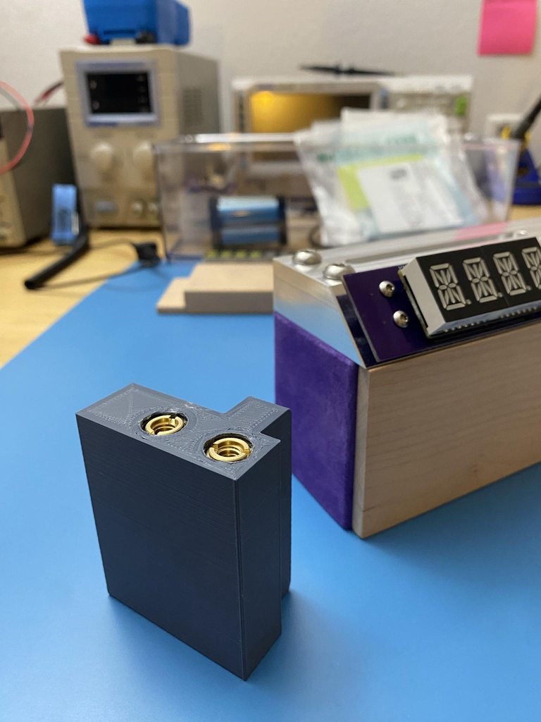
 upbeat lotus
Over break I worked on a react/tailwind landing page for the board I made to automate watering my plants; I am having 30 boards made and assembled of v1.1 and should have them soon, the v1 boards are fun to play with but v1.1 corrected one of the connector types pinout. https://growmax.opensensor.io/
Monitor and automate watering your home indoor grows; never let plants get too dry again with our custom parts and board powered by the Raspberry Pi Pico.
old spruce
upbeat lotus
Over break I worked on a react/tailwind landing page for the board I made to aut...
looks cool! How much current can the board supply?
upbeat lotus
old spruce
looks cool! How much current can the board supply?
Pico supports max of 300 mA, so its important in the software to only turn on one pump at a time, this allows the other sensors and things enough current extra, if more current is needed, then an I2C Relay board can be combined.
 broken rain
Just made a case for the raspberry pi zero 2 w and spy cam for anyone that wants it. https://www.printables.com/model/356931-pi-zero-spy-camera-slim-case

Printables.com
A case for the raspberry pi zero 2 w and spy camera. | Download free 3D printable STL models
 amber granite
Space mouse!!! It’s running Kmk with an kb2040


 exotic sierra
rancid kestrel
The E-Fidget is done! It works too!
exotic sierra
rancid kestrel
The E-Fidget is done! It works too!
I’m surprised you got away with so few capacitors for the RP2040
rancid kestrel
There's plenty over to the side. Not ideal, I know, but it's a small space
exotic sierra
The thing wants like 11 of them, 2 1uF and 9 0.1uF
rancid kestrel
I think they're all there, above the off-white JST connector
exotic sierra
Ah
rancid kestrel
It's a work in progress, hoping to fix in V2.1
exotic sierra
You have lots of space to the right of the RP2040, definitely consider moving them there 🙂
Overall looks good though
Nice work
rancid kestrel
Ok, will do for the next revision, thanks so much 🙂
Also gotta fix that ugly red jumper. Forgot to pull the EN pin of my 3.3V regulator high 🤦
exotic sierra
😅
cunning lava
my eevee pcbs arrived
 exotic sierra
cunning lava
my eevee pcbs arrived
exotic sierra
cunning lava
my eevee pcbs arrived
These are perfect
cunning lava
there is a little notch near one ear where the cnc router got confused, but I fixed it already
frosty topaz
cunning lava
my eevee pcbs arrived
I don’t even know what these are for, but I want them.
cunning lava
they do nothing
frosty topaz
Oh. Changes nothing. Is that just 4-color silkscreen? I should think of something cool for these…
cunning lava
it's a black pcb with transparent soldermask, white silkscreen and gold plating
oshpark's "after dark" theme
slim finch
So what are you doing to do for Rev2? Flareon, Vaporeon, or Jolteon?
exotic sierra
slim finch
So what are you doing to do for Rev2? Flareon, Vaporeon, or Jolteon?
Probably could do all of them with the colors of PCB available
cunning lava
slim finch
So what are you doing to do for Rev2? Flareon, Vaporeon, or Jolteon?
i was thinking umbreon in purple
jolteon is doable too, but I don't like its looks
rough root
cunning lava
my eevee pcbs arrived
Do you do your own drawing/art?
cunning lava
rough root
Do you do your own drawing/art?
yes
rough root
Nice! I have so many PCB idea but I'm limited by my skills
cunning lava
practice
or team up with an artist
there are many illustrators who do commissions relatively cheap too
wary atlas
cunning lava
my eevee pcbs arrived
I will pay you money for an Eevee
cunning lava
wary atlas
I will pay you money for an Eevee
just order them from oshpark at that link
wary atlas
 I didn't know I could do that! I shall do that!
wary atlas
cunning lava
just order them from oshpark at that link
Wait, there's no link
wary atlas
It's cool. Would that be 1 board is $18.95, or a set of 3 like in your photo? [and I guess "download" would be for making changes, like maybe adding LEDs? 👀 ]
exotic sierra
wary atlas
It's cool. Would that be 1 board is $18.95, or a set of 3 like in your photo? [a...
You get 3 for $18.95
burnt wyvern
cunning lava
my eevee pcbs arrived
This is such a cool design! Would be cool as a keychain too :)
 quartz latch
cardboard tracks made by half-cutting the cardboard to make it into a belt
feral orchid
Here are my two Qwiic/Stemma QT BLDC boards. Hopefully they can drive a hobby BLDC without overheating. Not as good of a design as the Eevee PCBs though.
 devout verge
Pun intended?
rough root
Heheh
 north valve
I've just posted more information on the mini slot machine I previewed on last week's Show & Tell show.
https://www.somenice.com/2023/01/the-micro-one-armed-bandit/
Looking forward to everyone's projects tonight
 pulsar mortar

Version 1.2 of my Coffee roaster board is up and running
Just have to connect the heat and let the PID loop do its thing 😄
Features (so far)
Adjustable drum speed
Adjustable heat (duh)
Adjustable Fan speed-I kind of figured I would need this if I want to do a slow roast with gentle air.
I'll be using a NEXTION display as the screen
 rain steppe
First large order of my dental motor system - assembly in progress…


Very tight on space at the moment - renting a new location in a month
hardy veldt
Didn't expect this hackjob to work as I winged it the entire time but it did. Fixed the middle mouse button since I like the mouse and its optical switches but the middle mouse is mechanical and it gave out pretty early. Turns out these switches are not only pin compatible (only two are really used and work as you expect), but they have the same pitch as your common headers. So I hacked away some plastic to fit the 3-pin, reduced the header to line up the switch vertically and it totally works again.


 exotic sierra
rain steppe
exotic sierra
rain steppe
Amazing to see this come to fruition after all the hard work you put in
rain steppe
exotic sierra
Amazing to see this come to fruition after all the hard work you put in
Thanks, yeah it’s been a long ride. I’ve learnt a ton along the way. Big thanks to you and all other contributors in hw-design for getting me there 🙂
upbeat lotus
After having 10 boards made of Growmax v1.0 and supporting my pinout mistake with cross over cables, I since corrected the design and had 40 boards v1.1 made -- already have sold one organically since my site launched on New Years, so I am pretty happy about that. Ask me anything about it.

 blazing apex
I made a front cover for the magtag https://www.thingiverse.com/thing:5784938 Also I made a project that displays the temperature that is being sent to adafruit.io from a pi zero in another room. Where do I put that code in case any one else wants to use it?

This is a front cover for the Adafruit Magtag. 4 X M3 screws are needed to screw into the Magtag. There are two versions: one with LED and light sensor holes and one without. The Fusion 360 file is also attached, it has the Magtag PCB board in the design to make changes easier.
wary atlas
Nice. I love the look of the filament changing over during the first layer.
Probably GitHub would be the best place for the code
blazing apex
Thanks 👍🏻
wary atlas
No problem :D
blazing apex

 wind linden

GitHub
Make your SAMD21 Arduino functions faster. Contribute to Bexin3/Speeduino development by creating an account on GitHub.
My first version of a library that has faster samd21 functions, it’s far from finished but makes ADC and PWM much faster and pwm frequency configurable
What other stuff to speed up?
feral orchid
Nice. I needed high-frequency pwm for a project a while ago. But that project is kinda dead now
Maybe speed up the DAC
And general GPIO (although that is usually accomplished by using the registers).
solar yew
https://www.youtube.com/shorts/aCM6yupru5k finished my "Gameboy" based on ATMega328p , 8x8 dot matrix controlled by shift registers. I wanted to impement "Snake" or "Tetris" game but the programming was hard for me so I stayed with "Simon Says" game for simple demonstration😭


A gameboy based on ATMega328p , 8x8 dot matrix controled by 3 shift registers ( 2 column , 1 rovv) , 5 control buttons and a buzzer. 3 AAA batteries 4,5V. 16MHz crystal
feral orchid
I got rotation! It's pretty slow right now, but if I figure out how to fine-tune the pid parameters, I should be able to get it going faster
feral orchid
That's exactly how hobby outrunner motors are supposed to work
grave gust
I finally finished it! The "sArCaStIc TyPeR!". This was my very first venture into a a lot of things, circuitpython being one. Coding period lol. I had an idea how to do any of it and kind of went for it in figuring out how to do it. LOTS of trial and error along the way but it was so much fun!
So this is pretty basic. It consists of a Seeduino Xiao RP2040 flashed with circuitpython and wired to .96" OLED and simple SPST switch. The circuitpython script, which is was what took me the longest to figure out having no expeerience, is pretty simple too. In the off position the switch will do nothing more than display "Normal Mode." When the switch is flipped to the on position it'll change the text on the screen to "sArCaStIc MoDe!" and start sending the capslock key code at an interval of .1 seconds. "tHaT wAy YoUr TeXt LoOkS lIkE tHiS!" lol
It's a stupid thing but the idea of this came about looking to make a gift for a friend of mine, and this is an odd, quirky little thing she does and I figured I would make it easier lol.
For the enclosure, I worked with someone to custom design it and then had it 3D printed. It's pretty neat!


 upbeat geyser
cunning lava
sorry https://oshpark.com/shared_projects/X7W8wMWh
upbeat geyser
cunning lava
sorry https://oshpark.com/shared_projects/X7W8wMWh
What is the SOT23-6 footprint for?
cunning lava
upbeat geyser
What is the SOT23-6 footprint for?
SAO connector
 jagged parrot
grave gust
I finally finished it! The "sArCaStIc TyPeR!". This was my very first venture in...
jagged parrot
grave gust
I finally finished it! The "sArCaStIc TyPeR!". This was my very first venture in...
This is fabulous!
grave gust
jagged parrot
This is fabulous!
Thank you!
north mural
@grave gust That is an awesome idea brought to reality. Congrats!
grave gust
north mural
<@233598862336458752> That is an awesome idea brought to reality. Congrats!
Thank you!
wary atlas
grave gust
I finally finished it! The "sArCaStIc TyPeR!". This was my very first venture in...
V2 idea: a few buttons that automatically type out any phrases she commonly types. I used that sort of function at work so I wouldn't have to type the same thing over and over and over and over again, lol
grave gust
wary atlas
V2 idea: a few buttons that automatically type out any phrases she commonly type...
That’s a good idea!
 untold briar
About 8 months ago, my daughter asked me to make her a cube of LEDs that she could control from her iPad. The hardest part was the 3D printed case, and we ended up doing just a grid for now, but we are still working on the cube!
The React webapp works on her iPad (recognizes multi touch) or a computer and mouse, or my touchscreen laptop. It posts to a lambda to write the JSON to S3, then pings the device using adafruit.io, then the microcontroller requests the full JSON from the S3.
It's using a feather huzzah and the propmaker wing.


 grave gust
Okay that is just too amazing!
dark cairn
Sd tolerances are nuts
This sd, did not register unless I pressed hard on the connector (downwards)
The fix:

One pass with my K tip.
Works btw.
 potent fox
nice fix
potent fox
My pcb I have been working on for about a month is almost ready to print. Id say probably a week worth of work is left before it is ready. I use Fritzing, that is why it is breadboards. Fritzing allows you to create circuits on breadboards then print the circuits onto pcbs.
 blazing apex
This is the finished Magtag temperature from Adafruit.IO if anyone would like to make suggestions https://github.com/aireng1/Magtag_Temperature_from_Adafruit.IO

GitHub
The Magtag reads and displays the temperature being sent to Adafruit.IO from a pi zero W in another location - GitHub - aireng1/Magtag_Temperature_from_Adafruit.IO: The Magtag reads and displays th...
wary atlas
untold briar
About 8 months ago, my daughter asked me to make her a cube of LEDs that she cou...
Super cool :D I have some suggestions for possible designs to make a cube
 rain charm
version 2 will have a custom pcb instead of all those wires
version 2 will have many different things instead of many different things
wary atlas
So the same, but different. Hehe
rain charm
been a fun process
sadly the i/o is at the top since the software doesn't want to rotate the screen consistently
wary atlas
Oof
rain charm
i just prefer having headphones come from the bottom of the device but it's not to be
wary atlas
Can you solder a headphone jack on a wire to the port and take it to the bottom?
rain charm
totally, and also expose the sd card would be ideal
but this one i have to just finish it, it's been 6 months and a couple of days a week
this one after much deliberation is going to my cousin, the next one will be for me ^^
wary atlas
V3 will be your best I'm sure! If you continue after V2 anyway, lol
rain charm
aha !
well the plans for version 2 are dockable and cleaner i/o with custom pcb and a clean snap fit
maybe haptics
wary atlas
Nice!
rain charm
software enhancements like battery status
wary atlas
Good to know how much battery you have, lol
rain charm
yes
the battery in this one is pretty bad, it's pisugar s plus and when it cuts power it doesn't really cut power
so my screen will randomly flicker
the screen has a backlight button, which doubles as power down.... shutdown is a two step process
wary atlas
Might be able to have your Pi signal the screen to turn off during shutdown
dark cairn
my rfm69 range testing package is looking like a pipe bomb
wary atlas
I don’t see a pipe 
blazing apex
Not sure if this is any help to you. I made a retropie cm3 in a Gameboy case a while back https://github.com/StonedEdge/Retro-Lite-CM4

GitHub
A CM4 gaming handheld, designed with the Switch Lite aesthetics in mind. Contains all STL files and code to build your own landscape retro handheld system. Co-project with Dmcke5. - GitHub - Stone...
 rain charm
that's basically what i plan to do for version 2. it's a great hobby and lots of fun
the retro lite cm4 is a very clean solution
yep you've basically got EVERYTHING
so cool
rain charm
blazing apex
Not sure if this is any help to you. I made a retropie cm3 in a Gameboy case a w...

 ember cliff
made some Tamaguinos to test out circuit board cutting. Did concept sketch to finished in 3 days last weekend


Then this weekend has all been about arcade controls, this was sketch to fab in about the same amount of time (arcade switch to usb keyboard translator)


 dim saddle
NeoPixels are among the many things my modded Otamatone is sporting 🙂
It's guts are based on a Electro Smith Daisy Seed (STM32H7). I've basically taken out all the original circuitry and replaced it, with the exception of the resistive touch strip. New brains, new speaker, new amp, SD reader, and 9dof sensor 🙂
wind linden
https://github.com/Bexin3/Snowduino-Null
Not yet tested as I am waiting for the pcb to get manufactured, but this includes KiCad files for a samc21 board compatible with uno layout, library for it, and a Speeduino library version for samc21 that allows for faster analog and pwm functions

GitHub
Speed up the functions on your SAMC21 Arduino compatible board - GitHub - Bexin3/Snowduino-Null: Speed up the functions on your SAMC21 Arduino compatible board
hardy veldt
Lots of firsts for this split flap clock project. First universal perfboard project, first stepper, first crimping (it's rather addictive), first external power rig (barrel can power stepper and board). (and first Arduino project, to control the steppers better) Which means a lot of trial and error, messups, and wasted parts. But I'm learning and it totally works now. Just waiting for laser cut parts for the clock itself.
 wary atlas
A Chinese clock kit I just got, proud of how neat and lined up all my parts are… too bad there’s a problem with it DX

 stark latch
wary atlas
A Chinese clock kit I just got, proud of how neat and lined up all my parts are…...
stark latch
wary atlas
A Chinese clock kit I just got, proud of how neat and lined up all my parts are…...
So, the bottom segment's out on all 6 digits? Best guess is a bad connection somewhere around the 7 resistors on the left or the IC pin connected to one of them. Got a scan of the schematic?
wary atlas
stark latch
So, the bottom segment's out on all 6 digits? Best guess is a bad connection som...
Mhmm, I was thinking maybe a bad component, Altho it was late when I finished… I’ll post in projects and in a bit with scans and all
pulsar mortar
Finally got my roaster to a point where I can roast
The only thing thats missing is the HMI stuff for the Nextion so I can use a display

The result
Its definitely a dark roast 🙂
The only thing Ive found that might be difficult is the load/unload process.
wary atlas
Oh, yeah, finally got the clock fully working thanks to the folks helping in the project channel! Turned out to be the pad for a resistor had broken away from the trace, so I just ran a bodge wire from that to the nearest display pin.


 gusty shard
This just arrived today.

 summer gazelle
Notice anything different about my 3DS?
 wary atlas
I don’t recall it having USB C :0
hardy veldt
This split flap clock is coming together rather well. This is based on scottbez1's split flap display but heavily modified for a clock design with flaps that I took from an existing battery-powered flap clock. Uses steppers to turn the spools, hall sensors to determine a "zero" point, rtc and wifi to maintain consistency. It does have drift errors but they're consistent and fixable via code.
 real marlin
gusty shard
This just arrived today.
real marlin
gusty shard
This just arrived today.
Are you plugging VSYS to GND?
Or no isn’t it wired to GPIO pin
gusty shard
It is GP15, set up for PWM.
hardy veldt
hardy veldt
This split flap clock is coming together rather well. This is based on scottbez1...
Done. This is the entire initialization sequence. Zero out then set to time. I need it to start at a consistent point since everything else, including the drift corrections, is based on that with a full reset once a day to be sure.
wary atlas
Beautiful!
Made a dual-color joule thief flashlight: jumper selection of red or white, button to power on (momentary contact, might swap for a switch?); back is kind of a mess, but that’ll be hidden, lol. Gonna make a case from scrap plastic and run it from a D battery, so should last a few years


 wise island
Made a RP2040 DVI/VGA board with a nrf24l01 as a wireless display. In the video an ESP32 is sending messages to the RP2040 to drive the display.

 wary atlas
Ohh, wireless display! That’s super cool!
That would be SUPER useful for digital signage purposes
 hard oriole
Here's a nOOd, ground wire, and aluminum armature wire in a clear heat shrink. I designed a base /battery holder. It lasted about 2 weeks of constant bending before it started shorting [a break in the nOOd right where anode attaches]. The aluminum proved very reposable but was not able to hold hard corners. I now have a version where I'm using a single brass rod for the armature and ground, with idea of just posing once.


 wary atlas
Made a cardboard battery compartment for my joule thief flashlight. Has a D cell battery, should last a long long time!

 broken rain

Printables.com
A case for the Adafruit ESP32-S2 Reverse TFT Feather. | Download free 3D printable STL models
 last jay
Designed this PCB earlier for transmitting data from another serial device using an hc-12 transceiver module

 exotic sierra
last jay
Designed this PCB earlier for transmitting data from another serial device using...
exotic sierra
last jay
Designed this PCB earlier for transmitting data from another serial device using...
Very cool
last jay
exotic sierra
Very cool
Thanks, I'm working on an Uno hat for the receiving end
It's got 3 LEDs and a buzzer to take advantage of the extensive space provided by the template
exotic sierra
last jay
It's got 3 LEDs and a buzzer to take advantage of the extensive space provided b...
Very nice, I hope it works on the first go! It’s a great feeling when that happens 🙂
last jay
I forgot to mention that I'm using a bmp280, not an adafruit one though
For measuring the battery temperature of the electric car we're using
 last jay
 ashen steeple
Messy for now, will clean up later
ashen steeple
Messy for now, will clean up later
OnePlus x Hasselblad?
ashen steeple
oneplus 9 pro
ashen steeple
::)
ashen steeple
yeah, not the best but it's ok as a general one
last jay
I yearn for the speed of a flagship phone, but a budget one will do until I'm not broke anymore
ashen steeple
my office is mostly just second hand stuff i got for free 🙂
last jay
Looks like you got pretty far
ashen steeple
can get alot for free here
last jay
Job?
I've gotten some XP era laptops from my dad's work before
I currently run Linux on one of them, which is an HP/Compaq that I call the slab
ashen steeple
in my previous work I did some dumpsterdiving and found a few nice laptops
but most of the stuff in office, poeopel just give away because hey need to get rid of it quickly
last jay
You wanna send one over? Could really use one about now 👀
ashen steeple
I sold the ones i got after fixing any issue 🙂
last jay
Welp
Almost managed to trade an old latitude D610 with dock for a newer Inspiron laptop
ashen steeple
someimes I find some nice deals on the second hand marked and sell for profit again right after 🙂
last jay
It had a dual core pentium with 3gb of ram and ran windows 10 somehow
ashen steeple
i run win10 on 2gb. it worked but is far from good
last jay
Yeah that would beyond suck
I was gonna run Linux on it but friend declined the trade
Kinda mad
ashen steeple
🙂
 jade palm
wise island
Made a RP2040 DVI/VGA board with a nrf24l01 as a wireless display. In the video...
jade palm
wise island
Made a RP2040 DVI/VGA board with a nrf24l01 as a wireless display. In the video...
That's a really nice concept! What kind of data are you sending over the ether? Is it raw video buffers, draw calls, displayio or something completely different?
wise island
jade palm
That's a really nice concept! What kind of data are you sending over the ether? ...
Thanks! On the client you use a RemoteDisplay class that then uses a transport object to send the data for each call. The RemoteDisplay implements the MCUFRIEND_kbv methods (extended Adafruit_GFX interface), but is not derived from it...
 scenic crown
Production pillbugs in and tested 
 exotic sierra
scenic crown
Production pillbugs in and tested <:yay:585696613507399692>
exotic sierra
scenic crown
Production pillbugs in and tested <:yay:585696613507399692>
These look so good
scenic crown
exotic sierra
These look so good
thank you! These are nrf52840 powered pin compatible blackpill replacements, specifically aimed at our mechanical keyboards
exotic sierra
scenic crown
thank you! These are nrf52840 powered pin compatible blackpill replacements, spe...
Very cool, I almost didn’t see the antenna on the ends. It all looks great! Are you bringing these on show and tell this week to talk about? Also, circuitpython support at all?
scenic crown
exotic sierra
Very cool, I almost didn’t see the antenna on the ends. It all looks great! Are ...
Already on the circuitpython support page. This is just the first batch of production units. I don't know anything about show and tell here, fairly new to the server.
 exotic sierra
Show And Tell happens every Wednesday at 7:30pm Eastern Time
They put a Streamyard link in the #live-broadcast-chat to join the show
scenic crown
Maybe next week? I should sit in on this one and see how it is done by regulars
exotic sierra
There are recordings on YouTube if you want to watch reruns 🙂
scenic crown
Thank you for the recommendation!
north mural
Show & Tell is for everyone of all skill levels. Works in progress are not just welcomed but also appreciated. It’s cool to watch people’s projects progress over time.
feral marsh
NeoPixel controller V2. There's an ESP32-S2 Feather visible underneath, but the board on top is the one I had fabbed at OSHPark, with a 74125 soldered in for the required 3.3v to 5.0v level shift. Red/green/black cable goes to a JST SM to feed the NeoPixels. Box is 3d printed, it's a rework of something I found on Thingiverse, it has the cutouts for a cable and the USB C connector.
This will ultimately connect to my WiFi, and ping a local NTP server for time. That will let it (A) turn on and off at sunset/sunrise, and (B) adjust the color scheme based on the date: Green for St. Paddy's in March, Red White and Blue for May 6th and July 4th, Orange and purple for Halloween, bright colors for Christmas, etc, etc.
 hardy veldt
Bit of a proof of concept. I've made myself a MIDI player that sends signals for our digital piano to play perfectly (hooray for General MIDI). But since I adapted it to use an RP2040, I want to take it one step further and have it drive neopixels (instead of relays connected to lights) on the second core based on the key being played in the octave. And with Scorpio, that opens up a lot more possibilities, including animations. It might not even need multicore (or scorpio for that matter) but it gives me an excuse to practice using them.
So far so good. I've isolated the MIDI messages I'm looking for, and I'm testing the multicore functionality with this LED test. Core0 generates random numbers while Core1 sets the LEDs. I'm just waiting for my scorpio and neopixels to really see if it works.
 dark cairn
 wary atlas
dark cairn
wary atlas
dark cairn
Ohhh, I’ve done this before, but yours is so clean… and I never thought to label mine XD
dark cairn
I am horrible at remembering pinouts.
I would be frying sdcards left and right if I didn't label it.
wary atlas
I just look it up every time like a dummy XD
near plume
+1 on the labeling. I should get a microminiature pen for labeling components that are too small to write on
dark cairn
Ljinux doesn't like the sd
it's instant on the board
using it as root really isn't viable
last jay
Newest iteration of my PCB
 solemn vector
Finally got the t-shirt plus some stickers from the Hacktoberfest team for contributing with the CircuitPython projects 🙂 🙌
 north mural
Congrats! 🎉 Great looking shirt. I tried to get one but failed 😦
solemn vector
Thanks! Maybe next time!
upbeat lotus
north mural
Congrats! 🎉 Great looking shirt. I tried to get one but failed 😦
Always this year -- pipenv backlog has plenty of issues I can help coach you on if its of interest.
I got the light themed shirt for 2022 🙂
My latest adafruit order arrived today and I've been working with the 128x128 grey scale display and the toggle touch sensor.


The blue board is the growmax board I developed as OpenSensor.io -- I also am using the Adafruit SCD-40x sensors -- lots of great adafruit products to pair with.
Having a slight issue with the touch toggle sensor though, sometimes when I turn it off, it comes back on within 10 seconds -- but not always. Like just now I had to turn it off 3 times now it seems to be off-off.
Using a PULL_DOWN on the pin, so not quite sure I can explain it. Seems to usually work ... but sometimes turns back on
pin = Pin(28, Pin.IN, Pin.PULL_DOWN)
pin.irq(trigger=Pin.IRQ_RISING|Pin.IRQ_FALLING, handler=toggle_display)
def toggle_display(pin):
if pin.value():
display.poweron()
else:
display.poweroff()
upbeat lotus
Ah I think its this from the data sheet:
Timeout configuration pin. Must be connected to either VSS,
VDD, OUT or an RC network. See Section 3.11 on page 11 for
details.
I have that pin floating right now 😕
Fortunately TIME and VDD pins are next to each other 💡 Just a dab of solder I think ...
Actually that just caused it to heat up and lock up, so this can't be right 🤔
upbeat lotus
So then I cut the timer jumper and it "works" with the VDD and TIME pin soldered together, but the display still randomly tuns back on. 🤷♂️
In fact, it turns on way more frequently after those solder/jumper changes 🤦
Ok, seems better when I specified the pin to not have pull up or pull down, but pull is None. Will see if it turns off on its own in 15 minutes (supposed to when TIME is connected to VDD).
Well I guess its no better, still turns on on its own ... if you have any ideas I'm all ears.
upbeat lotus
Is it possible that the ADC pins on the pico were causing this problem? I just switched from pin 26 to pin 20 and haven't seen the problem reoccur yet.
Nope nevermind, right after I typed that it happened again
north mural
Ask in the help-with-circuit-python channel. 😉
grand jay
made a cute little USB-C jumper/adapter board, so i can patch a PPK2 to measure VBUS currents without too much fuss. i might make a custom PCB version later that has selectable CC1/CC2 resistors on each side (right now it has the 5.1k device pulldowns from the breakouts)

i deliberately left the pins un-trimmed, so i can plug female Dupont jumpers on top of them (they're barely long enough)
upbeat lotus
north mural
Ask in the help-with-circuit-python channel. 😉
But I am using Micropython
north mural
ah, looks very similar. dunno i've never tried micropython yet.
but there are plenty of people in the circuit python help channel that also know micropython.
 timid vale
This is my ham radio Morse code beacon keyer. I'm using it for a school science project studying propagation. It automatically sends a test signal and CW identifications on 2 meters. It connects to my regular FM radio's mic jack, but the only connected wires are PTT and ground. It just keys PTT on and off, which generates CW because there is no audio to modulate the carrier.
If anyone wants to build their own, it's really easy. Any relay should work. I used an active on HIGH relay, but the code also supports active on LOW. You'll have to somehow connect it to a mic or ACCY jack on your radio to key the PTT line; how you do this will depend on your radio. For the code, just download the "Telegraph" library in the Arduino IDE; the code is in the "Morse Beacon" example sketch. Please remember to change the values in config.h; at least set it to your call sign.

This does require an amateur radio license for legal use on the air. Please check for and comply with any laws or regulations in your country; beacons and automatically controlled stations are, at least in the US, regulated differently than other types of stations. If you just want to test the code, set the pin to LED_BUILTIN and don't use a relay. It's okay to leave my call sign if you're only testing with an LED.
The code should work on any board compatible with the Arduino IDE; I have only tested it on an Uno, but I don't see any reason why it wouldn't work on any other board.
Also, please don't run it on a repeater or another frequency on which people are likely to be talking!
hardy veldt
Got it working. All 7 notes (A-G) mapped to an LED, with an extra 8th to (currently) emphasize it being a sharp/flat note on a keyboard. This one's playing to the tune of Fernando from the Arduino MD_MIDIFile library example (audio from PC speakers, but it should play well on a MIDI controller). It should adapt nicely to a neopixel concept, but I still need to figure out how to extend this to an entire strand with possibly a measure of randomness so they're not all evenly spaced out.
rough root
Made this egg
 calm badge
rough root
Made this egg
calm badge
rough root
Made this egg
are you related to faberge?? 🤣