#help-with-projects
1 messages · Page 3 of 1
 buoyant jackal
 wary dust
buoyant jackal
Did you buy the display from us? First try the examples here: <https://github.co...
wary dust
buoyant jackal
Did you buy the display from us? First try the examples here: <https://github.co...
I did buy it from Adafruit. I've tried a number of examples and can post them at the forum. All libraries and Circuit Python are the latest. Does the fact that the faded section shows up under Circuit Python 10's console print on the display indicate a faulty display.
 buoyant jackal
wary dust
I did buy it from Adafruit. I've tried a number of examples and can post them a...
buoyant jackal
wary dust
I did buy it from Adafruit. I've tried a number of examples and can post them a...
That's pretty fishy. Go ahead and post in the forums, and someone can try to reproduce. It sounds like a hardware problem.
wary dust
Thanks. Still post in the same Circuit Python link you sent originally or should I use Glowy Things? Appreciate the pointers and help. I'm always wondering where to start forums or discord or email.
buoyant jackal
wary dust
Thanks. Still post in the same Circuit Python link you sent originally or shoul...
It doesn't matter that much. You can post in CircuitPython since you tried CPy examples. We may end up replacing the display, but there will be some troubleshooting beforehand, so include some sharp closeups of the ribbon cable, etc.
I don't have one of these mytself, so I can't try to reproduce
 wooden yarrow
I'm new to electronics and working on a project where I need 5VDC for a microcontroller. I have 240VAC mains available, which I'm also using elsewhere in the circuit to power relays. What's the best way to step down 240VAC to 5VDC for the microcontroller?
 latent lion
A mains-usb adapter, like you use for charging your phone should work fine
 full prism
Or a little Meanwell or other decent quality PSU - does depend on the size of the project and how much you care about having to plug in a usb supply
If you want to be really tidy something like this might be useful: https://cpc.farnell.com/mean-well/irm-05-5/power-supply-ac-dc-5v-1a/dp/PW04745
 minor snow
wooden yarrow
I'm new to electronics and working on a project where I need 5VDC for a microcon...
minor snow
wooden yarrow
I'm new to electronics and working on a project where I need 5VDC for a microcon...
Along with what others have said, try to position the mains PSU closer to the relays rather than the microcontroller board, with a goal of keeping the span of wire between the PSU's output and the relays' input to below a certain maximum length. Since the amperage of most microcontroller boards are often trivial, it shouldn't require nearly as much effort to mitigate its lower amount of voltage drop, which is normally caused by a combination of excessive length and high amperage.
wooden yarrow
latent lion
A mains-usb adapter, like you use for charging your phone should work fine
But I need 240 in my circuit which is why im asking
I'm using an ESP32 to energize the coils of my relay, which in turn have 240VAC running across the contacts. I am already powering my ESP32 usingg the same charger I use for my phone (when not connected to my PC), and then I have a seperate cable for 240VAC. I'd like to eliminate having two power inputs (i.e, not having 2 wall sockets occupied) and rely on 1 cable.
minor snow
wooden yarrow
But I need 240 in my circuit which is why im asking
Please note: If using with high voltages (> 24V) use care and common sense! High voltages require experience, and are only for use by engineers who are comfortable with guidelines and know how to use them safely!
– https://learn.adafruit.com/adafruit-power-relay-featherwing
minor snow
wooden yarrow
whats the link for?
It's just the source of where I originally got the quote from.
wooden yarrow
OH Im sorry I thought it was a resource
minor snow
wooden yarrow
OH Im sorry I thought it was a resource
It's technically a resource of using one relay product in particular, but a lot of its advice is broadly applicable to other relays on the market.
wooden yarrow
Actually, I can use 24V. Through a power supply; something like this: https://www.jaycar.com.au/24vac-1a-unregulated-power-supply-bareends/p/MP3032
But I'm still wondering, whats the best way to step this down to 5VDC for usage with my microcontroller?
minor snow
wooden yarrow
Actually, I can use 24V. Through a power supply; something like this: https://ww...
What about using 12v? If that's a practical option for your use-case, then https://www.adafruit.com/product/1385 should be able to convert 12v into 5v.

Your power supply problems just got SOLVED! This little circuit board may look tiny but inside is a high efficiency DC/DC step-down converter which can output up to 3 Amp at 5V without the ...
wooden yarrow
It's worth noting that I'm controlling a 24VAC relay that is part of an existing circuit I did not design, so this relay cannot be changed. My plan is to use a digital pin on my board to output 3.3V, which will drive a transistor to switch a secondary 5V relay powered by the same 5V supply as the board. This secondary relay will then control the 24VAC going to the original 24VAC relay.
Is what I'm describing making sense? I do not mind drawing a crude wiring diagram as visual aid
minor snow
wooden yarrow
It's worth noting that I'm controlling a 24VAC relay that is part of an existing...
Are you sure that the relay operates at 24 VAC for its control signal? Although I haven't looked into too many different types of relays, most of the ones that I've looked into accept DC electricity for their control signal.
wooden yarrow
This is an industrial solenoid
It's activating range is between 24 to I think like 90 something AC
The 24VAC relay needs to be activated by a control signal, but the ESP32 cannot provide enough current directly. To solve this, I’m using a secondary 5V relay (but ESP outputs much lower than this AGAIN), so the ESP32 will control this relay via a transistor, which switches the 5V supply that powers the ESP32 itself. The secondary relay then handles switching the 24VAC to the main relay. I couldn’t find reliable relays that trigger directly from 3.3V, which is why the transistor stage is necessary.
I have a very informal education with electronics, so I apologize if the language I am using is not clear. I also realize I have zero idea how to visaully draw this.
minor snow
wooden yarrow
The 24VAC relay needs to be activated by a control signal, but the ESP32 cannot ...
BTW, there are some products on the market that are a pre-assembled combination of an ESP32, a relay (or two), and an integrated AC to DC power supply, all with an intention of it being user-programmable. Here's an inexhaustive list of them (it does also include some non-ESP32 options): https://devices.esphome.io/type/relay
Browse relay devices for ESPHome
wooden yarrow
the point isnt the relay, as I mentioned, there is a load which requires 24VAC, my question is, i want to eliminate having 2 power sources in this circuit, by the means of having a single unified source (24VAC) and stepping that down to 5VDC
 latent lion
You have two different voltages and both AC and DC currents, you need to split the supply at some point to achieve the different voltages, or have 2 separate supplies.
Unless you can switch to a 24VAC control circuit, there is no getting around that fact.
 vital storm
@wooden yarrow what i've always done when I needed something like that, is bought the cheapest 240v usb charger I can that puts out enough amps on the 5v side, taken it apart, and de-soldered the pins that plug into the wall and soldered in wires to attach to the AC voltage i'm working with. you're also gonna need a 240vac to 24vac transformer. if you wanna take the inexspensive route those are common for doorbells and furnace power. there are plenty of 240vac to 24vac transformers on amazon. The only thing about those that can be frustrating is that they tend to be a little bigger than desired. I unfortunately don't know about options other than a wire wound transformer for stepping down AC voltage.
 ripe garnet
anyone can help with i2c and break beam sensors, or is this wrong section
minor snow
ripe garnet
anyone can help with i2c and break beam sensors, or is this wrong section
…, or is this wrong section
If you're coding the project in CircuitPython, then #help-with-circuitpython would be the proper channel. Likewise, if you're instead coding the project using the Arduino IDE, then #help-with-arduino would be the proper channel. Otherwise, this is a good catch-all channel to ask most other kinds of questions.
ripe garnet
basically i have a 3.3v i2c bus running to a 3017 expander. I want to connect a few 3mm break beam sensors, so do they have to be 3.3v or can they have a direct 5v supply without causing issues to the i2c bus
minor snow
ripe garnet
basically i have a 3.3v i2c bus running to a 3017 expander. I want to connect a...
BTW, the "MCP2" prefix of your so-called "3017 expander" is a very important detail. Without the full part number of the chip being utilized, it's difficult for others to understand what exactly you're referring to.
ripe garnet
Adafruit MCP23017
minor snow
ripe garnet
Adafruit MCP23017
If you read chapter 1 of the latest revision of its datasheet, it basically says that as long as the MCP23017 chip itself is directly powered with a 5V power supply, then it'll accept either 5V or 3.3V digital I/O.
 noble rune
Hi folks. I've got a Feather ESP32S3, and I'm building via Zephyr for it. I've got a breakout board with an SGP40 connected via the STEMMA QT port. I've got the breakout board LED lit by setting gpio 21 high (like the neopixel_pwr in the board dts), but I'm unsure why that works, since the i2c_reg is on 7. Probably a silly question, but it wasn't clear after poring over the docs.
buoyant jackal
noble rune
Hi folks. I've got a Feather ESP32S3, and I'm building via Zephyr for it. I've g...
The default pin state may be set to high, using the internal pull-up. That is what ESP-IDF does, and Espressif says that is the lowest power state for an unused pin (surprisingly).
try setting GPIO21 low deliberately and see if the power goes off. Try same with GPIO7.

The EN pin is active high, btw.
did you have to set GPIO21 high to make the breakout power LED come on?
noble rune
I did, yea - the board is definitely unpowered otherwise (I can't make a sensor reading without setting GPIO21 high either)
buoyant jackal
is it the plain Feather ESP32-S3?
noble rune
it's the esp32s3 tft
buoyant jackal
reverse tft or regular?
noble rune
regular
buoyant jackal
 noble rune
My app overlay isn't doing much, so the generated dts is almost entirely standard except trying to power the connector
ooo
buoyant jackal
I think you are looking at the wrong schematic. TFT S3 has I2C power on 21
regular S3 Feather has it on 7
noble rune
yea that looks like what I'm seeing, do you happen to have a link
buoyant jackal
no problem! there ca be a lot of pin rearrangement for routing or other reasons between Feathers
noble rune
yea, I think the lesson to double check which version i'm looking at is valuable
ripe garnet
minor snow
If you read chapter 1 of [the latest revision of its datasheet](https://ww1.micr...
the MCP23017 is powered from the i2c bus chained through a PCA9685, which is getting supply from a DCC-EX device supplying 3.3v. Obviously the servos are getting their own 5v supply on the pca9685. My dilemma is, if i use a direct 5v supply to the Break beam sensor pwr/Gnd, will this cause harm to the devices on the i2c bus that are only supplied via the 3.3v. The sensors are only connected to the MCP23017 via the data pin
minor snow
ripe garnet
the MCP23017 is powered from the i2c bus chained through a PCA9685, which is get...
Although it's somewhat challenging to interpret what has been stated within the MCP23017 datasheet, I'm pretty sure that as long as its Vᴅᴅ input pin has 5V power, it can handle any combination of 3.3V and/or 5V logic levels on most I/O pins.
ripe garnet
Well the MCP23017 is connected via quiik connector, so is only receiving 3.3v from the bus. Ive been led to believe that powering the sensors directly with 5v could damage the i2c bus, as apparently the gpio pin will receive 5v from the sensors
i just assumed that as the servo board has its own power source of 5v for the servos, i could do the same with the sensors, but seems i could be wrong
minor snow
ripe garnet
Well the MCP23017 is connected via quiik connector, so is only receiving 3.3v fr...
Some (but not all) Qwiic-compatible breakout boards have an on-board 3.3VDC to 5VDC boost converter. https://learn.adafruit.com/introducing-adafruit-stemma-qt/stemma-qt-comparison and https://learn.adafruit.com/introducing-adafruit-stemma-qt/sparkfun-qwiic have some additional details.
 wide creek
I'm going to repost my questions here that I posted in the chat. Hi I'm new here and I'm just asking for the sake of a cosplay project on what you recommend.
I have all of these in my cart so far. But I need the battery packs and wires that I can plug in and out of. Also, I've been watching Kamui cosplay's tutorials on LED strips and I just need the right ones for what I want.

This is the cosplay I'll be doing, Athena from Epic the musical. I just need some lights for the spear with a small enough switch the flexible silicone light is for her sheild. And tiny lights for her tiara please. What do you reccommend? I don't mind having to copy a code for the strips.

And I'm very sorry but I need these questions answered ASAP because Katsucon is coming soon and I need to work on it quickly to avoid a bad crunch.
buoyant jackal
wide creek
I have all of these in my cart so far. But I need the battery packs and wires th...
Check out https://www.adafruit.com/product/5768 (prop-maker in a single chip
https://www.adafruit.com/product/5650 (for multiple strips
The Adafruit Feather series gives you lots of options for a small, portable, rechargeable microcontroller board. By picking a feather and stacking on a FeatherWing you can create advanced ...
If there is one thing Adafruit is known for, its mega-blinky-fun-rainbow-LEDs. We just love sticking NeoPixels anywhere and everywhere. When we saw the new 'PIO' peripheral on ...
minor snow
buoyant jackal
Check out https://www.adafruit.com/product/5768 (prop-maker in a single chip
htt...
Yep, I previously sent them a link to an example project that makes use of the latter: #general-chat message
 buoyant needle
What is clear light? https://www.adafruit.com/product/3595
vital storm
@buoyant needle valid question. I think the intent is "white" light in contrast to red, blue, green or any color. As in "light clear of any color filter".
buoyant needle
Thank you! That makes sense
buoyant needle
How would I turn the values into a visible color? Even putting something red in front of the sensor, it gets a lot of blue and green. I was kind of hoping it would just map to hex codes easily
vital storm
that I have no idea.... type the prodfuct into the "learn" search bar on adafruits website and see if any adafruit guides have already done that
 dusky lion
buoyant needle
How would I turn the values into a visible color? Even putting something red in ...
dusky lion
buoyant needle
How would I turn the values into a visible color? Even putting something red in ...
(just curious, I haven't used this sensor) are you able to share the code used for the test, and some of the values? Some other sensors I've tried needed some sort of calibration or more time to accumulate results
buoyant needle
vital storm
that I have no idea.... type the prodfuct into the "learn" search bar on adafrui...
There doesn't seem to be much other than how to read the raw values
buoyant needle
dusky lion
(just curious, I haven't used this sensor) are you able to share the code used f...
import board
from adafruit_apds9960.apds9960 import APDS9960
from time import sleep

i2c = board.STEMMA_I2C()

sensor1 = APDS9960(i2c)
sensor1.enable_color = True

while True:
    if sensor1.color_data_ready:
        print()
        r, g, b, c = sensor1.color_data
        print('Red: {0}, Green: {1}, Blue: {2}, Clear: {3}'.format(r, g, b, c))
        if c > 0:
            print('Red: {0}, Green: {1}, Blue: {2}'.format(r*256/c, g*256/c, b*256/c))

    sleep(1)
I've printed a little black surround to keep external light from coming in, and I put a piece of black electrical tape over the green LED to prevent that from affecting the results.
Here are some results from hovering over my white shirt:
Red: 36, Green: 23, Blue: 21, Clear: 72
Red: 128.0, Green: 81.7778, Blue: 74.6667

Red: 28, Green: 18, Blue: 16, Clear: 55
Red: 130.327, Green: 83.7818, Blue: 74.4727

Red: 29, Green: 19, Blue: 17, Clear: 57
Red: 130.246, Green: 85.3333, Blue: 76.3509

Red: 30, Green: 19, Blue: 18, Clear: 59
Red: 130.169, Green: 82.4407, Blue: 78.1017
Pretty good from hovering over my black phone:
Red: 0, Green: 0, Blue: 0, Clear: 1
Red: 0.0, Green: 0.0, Blue: 0.0

Red: 0, Green: 0, Blue: 0, Clear: 1
Red: 0.0, Green: 0.0, Blue: 0.0

Red: 0, Green: 0, Blue: 0, Clear: 1
Red: 0.0, Green: 0.0, Blue: 0.0

Red: 0, Green: 1, Blue: 0, Clear: 1
Red: 0.0, Green: 256.0, Blue: 0.0

Red: 0, Green: 1, Blue: 0, Clear: 1
Red: 0.0, Green: 256.0, Blue: 0.0

Red: 0, Green: 0, Blue: 0, Clear: 1
Red: 0.0, Green: 0.0, Blue: 0.0

Red: 0, Green: 0, Blue: 0, Clear: 1
Red: 0.0, Green: 0.0, Blue: 0.0

Red: 0, Green: 0, Blue: 0, Clear: 1
Red: 0.0, Green: 0.0, Blue: 0.0

Red: 0, Green: 0, Blue: 0, Clear: 1
Red: 0.0, Green: 0.0, Blue: 0.0

Red: 0, Green: 0, Blue: 0, Clear: 1
Red: 0.0, Green: 0.0, Blue: 0.0
Orange toy (in shadow since the sensor is over it):
Red: 107, Green: 44, Blue: 41, Clear: 172
Red: 159.256, Green: 65.4884, Blue: 61.0233

Red: 64, Green: 19, Blue: 18, Clear: 85
Red: 192.753, Green: 57.2235, Blue: 54.2118

Red: 59, Green: 18, Blue: 17, Clear: 80
Red: 188.8, Green: 57.6, Blue: 54.4

Red: 54, Green: 17, Blue: 16, Clear: 73
Red: 189.37, Green: 59.6164, Blue: 56.1096

Red: 52, Green: 16, Blue: 15, Clear: 70
Red: 190.171, Green: 58.5143, Blue: 54.8571

Red: 58, Green: 17, Blue: 17, Clear: 78
Red: 190.359, Green: 55.7949, Blue: 55.7949
So, not nonsense numbers but not color accurate
Orange toy from the side:
Red: 69, Green: 22, Blue: 21, Clear: 96
Red: 184.0, Green: 58.6667, Blue: 56.0

Red: 89, Green: 44, Blue: 37, Clear: 133
Red: 171.308, Green: 84.6917, Blue: 71.218

Red: 94, Green: 53, Blue: 42, Clear: 144
Red: 167.111, Green: 94.2222, Blue: 74.6667

Red: 96, Green: 57, Blue: 45, Clear: 147
Red: 167.184, Green: 99.2653, Blue: 78.3673

Red: 96, Green: 56, Blue: 44, Clear: 147
Red: 167.184, Green: 97.5238, Blue: 76.6258
Have you found tweaking the gain and/or adc time helpful? (https://docs.circuitpython.org/projects/apds9960/en/latest/api.html#adafruit_apds9960.apds9960.APDS9960.color_data)
One strange thing I see is the results should be a 16 bit value, wonder why they seem to be capped at 255
 lusty wind
dusky lion
Have you found tweaking the gain and/or adc time helpful? (https://docs.circuitp...
lusty wind
dusky lion
Have you found tweaking the gain and/or adc time helpful? (https://docs.circuitp...
255 x 255 x 255 =16,581,375
buoyant needle
The second line is scaled to 256. The first line, I can get it higher with sensor1.color_gain = 3, which seems to be the max according to the table in the comments, but still max like 16k unless I shine my phone torch directly on it
The max is 65k if I shine the torch on it, though.
It seems to be more sensitive to Red, though - even with the torch, it's more likely to hit 65k on the Red before it goes there on the Green or Blue
dusky lion
buoyant needle
It seems to be more sensitive to Red, though - even with the torch, it's more li...
Ack. Looking at the datasheet, it looks like the r and g sensitivities are comparable, but the b is about half. You may need to calibrate the values for a given gain and integration time to get RGB equivalents.
https://cdn.sparkfun.com/assets/learn_tutorials/3/2/1/Avago-APDS-9960-datasheet.pdf
buoyant needle
dusky lion
Ack. Looking at the datasheet, it looks like the r and g sensitivities are compa...
Oof, thank you. That's a lot of reading but I will dig into it.
I also have the OPT4048 but couldn't figure out how to get from CIE to RGB so put that one away to focus on the APDS-9960.
dusky lion
Re: calibration, just meant - scale each channel against whatever you get in the second line for the bluest blue, reddest red etc.
Good luck 👍🏿
buoyant needle
Thank you
Does that need to be done individually for each board or can it be applied to all boards of the same type?
I guess individually, otherwise there would be recommended values already
dusky lion
buoyant needle
I guess individually, otherwise there would be recommended values already
You might be right. In the other sensor I tested, it also depended on how the thing was being measured so I found it was quite finicky. Out of curiosity What is your use for the sensor?
buoyant needle
dusky lion
You might be right. In the other sensor I tested, it also depended on how the th...
I'm trying to make a tool for blind individuals to be able to tell the color of items (e.g., clothing). They exist but are expensive.
I've ordered three different sensors to test them out. Also might just try to get a small camera and take/process pictures.
Just seemed like the sensors existed so might as well use them.. but not if I can't get accurate colors.
dusky lion
buoyant needle
I'm trying to make a tool for blind individuals to be able to tell the color of ...
Very cool. Maybe if you find calibrating against a color wheel or something gives adequate results, I guess there might be a way to get it usable.
buoyant needle
Thank you for the help. I'll keep trying until I figure something out.
lusty wind
buoyant needle
I'm trying to make a tool for blind individuals to be able to tell the color of ...
Your results will depend a great deal on the ambient light since the spectrum of reflected light on an object is determined first by the light source. So you'll need to be very consistent on both the light source and the precise distance to the fabric. As you probably already know, there is no such thing as "white light", it always has a color temperature. So if you use LEDs for your light source, you'd be best to mount them in some kind of armature that would hold them at a specific distance from the sensed object, and calibrate your sensor using that light source.
buoyant needle
lusty wind
Your results will depend a great deal on the ambient light since the spectrum of...
That makes sense. I'll put together an enclosure with an LED (and a divider between the LED and the sensor so it's just reflected light coming at the sensor) and test from there.
lusty wind
buoyant needle
That makes sense. I'll put together an enclosure with an LED (and a divider bet...
You'll also want to test a variety of different amounts of light, maybe PWM your LEDs so you can control the brightness. There will be an optimal amount of white light that will illuminate the fabric, after that you'll start to overdrive the system and end up with more of your light source than your reflected light. A bit like looking into the sun, you can't see much.
buoyant needle
Thank you! That's very helpful. I will definitely PWM!
vital storm
@buoyant needle I can assure you, as someone partially colorblind, even just having red, green, and blue, and clear sorted by which are the strongest would help. Instead of asking for help wether or not a shirt is blue or purple I could see that the red value is lower so it's probably blue. Or losing something red in the grass I could probably use that sensor and when the red spiked I'd know that I'm atleast close to what I'm looking for. It'd certainly be more useful than the "colorblind glasses".
buoyant jackal
I am red-insensitive. I have a couple of iPhone apps that identify colors for me.
you could use those for some kind of calibration, maybe.
wooden yarrow
vital storm
<@753495385988923394> what i've always done when I needed something like that, i...
Thank you so much!
finally an actual answer
I dont want two voltage sources in my circuit
lusty wind
wooden yarrow
Thank you so much!
There are actually (at least) two options here: a step-down transformer or a switching power supply. The latter are what you normally see as laptop power supplies, small black boxes without a transformer internally. So they're lighter and stable, and usually with lower EMI and cheaper since they don't involve a large block of iron with copper coils. I don't know that I'd recommend messing around with 240VAC if you don't really know what you're doing, it's quite dangerous actually.
vital storm
@wooden yarrow you're very welcome!
 stiff scroll
Has anyone here used i2c on a Vivid Unit? Just spent a day trying to figure out if I fried/shorted ony of my ANOs (at 0x51) - but testing it on other microcontrollers it was being detected and working fine - so I tried a different one that was being detected at the default address (0x49) and it was detected. I reconnected the header on the one that was 0x51 so that it was the default address 0x49 again and it was detected fine. Seems like there may be an issue or conflict somewhere? Has anyone ever had issues with specific i2c addresses on different devices? Polling any of the i2c busses without anything connected doesn't show anything at that address
dusky lion
(I don't have that SBC) but just wondering:
Are you using i2cdetect to check nothing's connected?
Is 0x51 unavailable on both I2C buses?
stiff scroll
Yeah, I checked all 5 of the I2C busses. The reserved addresses on each bus are marked with UU. Nothing shows up on i2c-2 though
dusky lion
stiff scroll
Yeah, I checked all 5 of the I2C busses. The reserved addresses on each bus ar...
(Didn't realize it had 5 i2c buses, interesting.)
- both ANOs work at 0x49 and 0x51 on other MCUs
- both ANOs only work on 0x49 on all 5 buses on the Vivid
- i2cdetect on all buses show 0x51 as being free
is that correct? (Don't have any ideas, but hopefully someone else might.)
stiff scroll
dusky lion
(Didn't realize it had 5 i2c buses, interesting.)
- both ANOs work at 0x49 and ...
Yeah, thats mostly correct. I think it actually has more than 5 - it has 4 GPIO banks each each one has 2 sets of pins that can be set to I2C - but I'm not sure all of them can be configured for i2c (and also only a subset are exposed as pins - most are for internal use by the board/the rockchip soc it uses) Only 2 of the i2c's are available on the gpio pins - i2c-2 and i2c-7
- Updating: Manufacturer replied to me - they have a device that uses 0x51 so they tried it and it worked. I don't have another device to try at that address - but its either the specific ANO I had at 0x51 or something with my environment setup.
 warm jay
Got a bit of a specific question again.
I have a breakout board with a capacitive touch switch on it to turn an LED on and off.
I soldered a LED strip to it and it was working fine over several months.
But recently it seemed to stop working. The control LED on the board still turns on and off but the LED strip not.
I assume the MOSFET on the board somehow got defective.
But I don't really understand why that would happen.
And how to prevent it.
Any ideas?
buoyant jackal
warm jay
Got a bit of a specific question again.
I have a breakout board with a capaciti...
what kind of LED strip and what is the breakout board? You could have overloaded the switching transistor that controls the LED, but that might also be current limited and couldn't be overloaded. It depends on the circuitry.

 latent lion
Looking at those pictures, it looks like the LED could have burnt out. There's what looks like some charring on the back from overheating
warm jay
ah no I think its some glue they used
I have another board which is unused which has the same
I assume it the LED strip overloaded something like the transistor as @buoyant jackal mentioned.
But I am not sure how I can find out what the save amount of current would be
It was working fine for several weeks before
buoyant jackal
warm jay
It was working fine for several weeks before
"fine" does not necessarily mean it was not overloaded and finally failed
latent lion
It's a similar misconception to fuses. In the UK we have fuses in plugs at either 3A or 13A and many believe they blow if the current exceeds that value. Where as the reality is you can pump 14A through a 13A fuse for months, in some circumstances even years, before it blows. And then its the heat that causes it to blow, not the energy. they blow quickly with a sudden surge of energy, typically 5x the rated current.
Many electrical components work in the same way. They have a threshold that they can operate safely at and over that will result in damage. A little over and it could take days or even weeks before it sustains irreparable damage.
warm jay
What component would I need to look into to find out which one gets overloaded?
buoyant jackal
no schematic, so pretty hard to tell without deeper reverse engineering. Maybe find something else that's more purpose-built for what you need
warm jay
will try to see if I can find one
wide creek
Okay guys I made a post on another part of the server.


This is what I want to do with some sketched annotations and plans.
So far this is the kind of lighting I was able to do, using only fairy lights. I just want my lights to turn on like this and the switch is in an easy reach.
So can anyone help please?
I just want to make my project glow and not be as splotchy as fairy lights.
dusky lion
wide creek
I just want to make my project glow and not be as splotchy as fairy lights.
(don't know much about this, but might it be an option to get ideas via some of the models? This came up with your project)
https://g.co/gemini/share/38bf90b6c3c9
wide creek
dusky lion
(don't know much about this, but might it be an option to get ideas via some of ...
I would appreciate it without the use of ai answers please.
latent lion
wide creek
I just want to make my project glow and not be as splotchy as fairy lights.
I think you want an LED tape, with them spaced closer together, instead of a string of lights. How you power them might be an issue though
wide creek
latent lion
I think you want an LED tape, with them spaced closer together, instead of a str...
Yes and I just want to be able to cut the tape and be able to plug it in and out of the switches or something like that.
Does Adafruit have an LED tape I can cut?
latent lion
I don’t know if they do?
Some tapes can get quite hot and need to be placed into an aluminium rail that acts as a heat sink, then a frosted diffuser goes over to give the appearance of a single unbroken line of light
wide creek
latent lion
I don’t know if they do?
Some tapes can get quite hot and need to be placed int...
This is why I wanted some strips I could wire together. I just want some strips I can cut and put under the EVA foam and a proper switch and battery pack for each of them.
Sorry I'm just a bit frustrated because I just want a simple answer for product recommendations.
I'm a bit stressed.
latent lion
wide creek
Sorry I'm just a bit frustrated because I just want a simple answer for product ...
I just found these on the adafruit site when searching for ‘LED’ https://www.adafruit.com/search?q=led&p=9
Adafruit Industries, Unique & fun DIY electronics and kits : Search Results -
A few of these could work, 300mm is about 12” long https://www.adafruit.com/product/5503
Our favorite food when hacking on code or electronics is a hot bowl of noodles - and around NYC these are often called 'noods'! What we've got here are flexible LED noodles, in ...
wide creek
latent lion
A few of these could work, 300mm is about 12” long https://www.adafruit.com/prod...
But I can't cut them,
latent lion
No, but that prop looks longer than 300mm, so you’d need more than one and you can just overlap the ends so there’s no gaps
latent lion
Ok, sorry, I misunderstood the application.
wide creek
This is what I mean by being able to plug it in and out


When I plug it in I can turn it on and it doesn't need to be connected 24/7 to make sure it works.
latent lion
I’ve just seen they also do 600mm and 1200mm (approximately 2’ and 4’ respectively)
wide creek
I just want strips I can put underneath the foam on my bodice that I can cut to size and then be able to hide the switches in the back of my costume.
But I need the correct battery and switches to plug and unplug them without breaking them so I can turn them on and off whenever I want to.
latent lion
A lot of the tapes will need 12v power, which cannot be supplied via usb
wide creek
latent lion
A lot of the tapes will need 12v power, which cannot be supplied via usb
No no no It's an example of plugging and unplugging.
Not the cable.
Because I need to be able to get out of my bodice.
I don't know if I can unplug it without it breaking that's why.
latent lion
wide creek
But I need the correct battery and switches to plug and unplug them without brea...
Ok, that helps. You can achieve plugging/unplugging with molex type plugs. They switch can either be mounted to the battery pack, or to the bodice
wide creek
latent lion
Ok, that helps. You can achieve plugging/unplugging with molex type plugs. They ...
Good good a molex type plug, does adafruit sell that and can it go with the LED strips that can be cut?
Would I need a chip for programming or anything?
latent lion
If you want to put breaks in the LED strip up the side of the bodice, then mag connectors might be a better option
latent lion
If you want simple on/off, no you shouldn’t need a controller. If you want anything else, you might
wide creek
latent lion
If you want simple on/off, no you shouldn’t need a controller. If you want anyth...
Then what do you recommend?
latent lion
I don’t know if adafruit sells everything you’d need, I’m fairly new to a lot of what they sell, sorry
wide creek
Okay this is stressing me out even more.
Can anyone with experience in LEDs from adafruit answer please?
I'm so sorry I'm just getting stressed because these answers are going in circles.
For me at least.
I just wanted product recommendations, that's all.
 limber patio
i'm learning about surge protection and i'm looking to design and build my own surge protector for learning purposes. I encountered GDTs and thought to use them, but their specifications are confusing. they specify a DC breakover/sparkover voltage, and an impulse sparkover voltage, which is much higher. If i wanted to use a GDT paired with MOVs, where two MOVs would be connected in series from line to neutral, and a GDT would be connected from the node in the middle to ground, what specification should i care about? the DC breakover? the impulse breakover?
If i were to have just a GDT between line and neutral, and i'm on a 120VAC region, does the DC breakover need to be above 170V?
I haven't been able to find good information on this, and the various robots i've asked have been useless.
thank you!
 cunning saffron
@limber patio That's out of scope for this server, given the risks of harm or damage.
limber patio
cunning saffron
<@196362143099125760> That's out of scope for this server, given the risks of ha...
i just want to understand the specifications of a component, everywhere it seems like that's forbidden illegal knowledge. at my university they just breezed right through the concept of surge protection existing, and the name of the components, but they were never truly explained, and now that i want to learn what the specifications mean, it's treated everywhere like if i was asking for instructions on how to build a nuclear weapon. the white papers all assume you already know how those devices work.
if not in university, and not on the internet, where else can one learn about these devices?
this is so frustrating.
i'm just going to get a bunch and learn through experimentation at the university's high voltage lab. and because no one wants to help(if there's actually anyone that knows how these things work...) that experimentation might be riskier because i don't know how to interpret the specifications, and sharing that knowledge is apparently worse than murder!
i'm 4 classes away from becoming an EE, with holes in my knowledge that everyone thinks should remain unfilled!
for many purposes the DC equivalent of an AC waveform is of significance. for these devices there's no mention of that. they specify the dV/dt for their DC breakover specification, but there's also no mention of what happens with low frequency AC, only impulse, at very high dV/dt, or DC, at very low dV/dt, but what happens in the middle? what happens to the gas at 50 or 60 Hz? the repeated ionization causes a conducting channel to form if we use these devices on higher AC voltage than the DC breakover? no one knows, apparently!
latent lion
limber patio
i just want to understand the specifications of a component, everywhere it seems...
I agree with anecdata that it's out of scope of a serve like this. But you might get some help finding answers if you reach out to the tech team at Surge Protection Devices (https://www.surgedevices.co.uk/). They're an independent company in the UK who make commercial devices for the UK and international markets.
cunning saffron
...or ask your professor for help, directly or for pointers to resources
limber patio
cunning saffron
...or ask your professor for help, directly or for pointers to resources
yeah, i'm going to do this once this semester starts, it still sucks to have to wait for that in the age of information ad in a moment when i'm eager to learn while on break. anyway. thank you
i want to truly understand these things. i want to learn as much as i can about them, i don't want or care about mindlessly assembling a schematic someone else drew
 midnight sphinx
Hey! I'm trying to build a controller using IMU sensors. Trynna map imu axes into Unity. I was planning on using the MPU9250 but the one I bought ended up being a fake one. I don't know what sensor to use now. Any suggestions?
limber patio
latent lion
I agree with anecdata that it's out of scope of a serve like this. But you might...
thank you, i'll contact them!
buoyant needle
What is this resistor on the right for on a QT Py RP2040?
 limber patio
buoyant needle
What is this resistor on the right for on a QT Py RP2040?
limber patio
buoyant needle
What is this resistor on the right for on a QT Py RP2040?
that is most likely a capacitor, but no idea what value
buoyant needle
I ask because I broke it off by accident but everything seems to be running fine
buoyant jackal
buoyant needle
I ask because I broke it off by accident but everything seems to be running fine
Yes, that looks like C10, a 1uF bypass cap that reduces electrical noise, etc.
it will work without it but you may encounter glitches, or issues with noisy power supplies, etc. You could solder another 1uF cap there, even one with leads, maybe
or if it works, don't worry about it for now
I looked this up by importing the Eagle files into Kicad and locating the bypass caps
buoyant needle
buoyant jackal
I looked this up by importing the Eagle files into Kicad and locating the bypass...
Thank you!
 molten iris
 leaden owl
anyone here experienced with rp2040 programming?
leaden owl
anyone here experienced with rp2040 programming?
There are some folks familiar with the rp2040 - it's best to ask your question and when they're around, if they know, they'll speak up
leaden owl
molten iris
There are some folks familiar with the rp2040 - it's best to ask your question a...
can i link files here?
molten iris
I think so? Not sure what you're trying to do exactly
leaden owl
send a zip of my source code
molten iris
I don't see why not
Not sure how many folks will take a look, folks usually link to their source repositories
anyway, I have to run, good luck!
leaden owl
oh ok im gonna put it on github, thanks, bye
my issue is weird, if i enable the state machine handling the sdi data(for init, later its not used) my clock/data sm starts choking(second image) and first image is normal behavior aka sdi machine disabled(lines 139/140 are commented out)


github link
https://github.com/404DEVV/hda2040_firmware

GitHub
Contribute to 404DEVV/hda2040_firmware development by creating an account on GitHub.
buoyant jackal
leaden owl
my issue is weird, if i enable the state machine handling the sdi data(for init,...
another place to ask about regular pico-sdk and PIO programming is in https://forums.raspberrypi.com/viewforum.php?f=143
 placid sinew
Hey everyone! 👋
I made an open-source project called EmbeddedController. It’s all about messing around with microcontrollers — buttons, LEDs, and other stuff — and learning how hardware and code talk to each other. I’m 16 and learning step by step, and you can contribute as well. Would be happy if you ⭐ it!
https://github.com/CoreControlLabs/EmbeddedController

GitHub
Contribute to CoreControlLabs/EmbeddedController development by creating an account on GitHub.
leaden owl
buoyant jackal
another place to ask about regular pico-sdk and PIO programming is in <https://f...
yeah but im not sure because i am using the arduino framework
buoyant jackal
leaden owl
yeah but im not sure because i am using the arduino framework
ah, sorry, I didn't look closely enough. If you have a specific PIO q that could be reduced to "what's wrong with this PIO program" (as opposed to all the Arduino API), then the rpi forums would be good.
I would say try to come up with a minimal example that shows the problem
leaden owl
im gonna go ask there, i am mostly using arduino for like the toolchain and settings, im mostly using sdk functions, thanks anyway
warm jay
Once again a specific question:
I have 2 metal parts that are touching eachother.
The surface where they touch is around 6 mm wide and 2 mm height.
The surfaces where they meet is not perfectly flat.
I want to push some glue into the thin gap so it's more sturdy.
I tried some super glue earlier with a toothpick but it's not ideal. The glue sometimes got stuck on the surface and became white and it did not look great.
- I can't separate the parts to apply the glue.
- the glue needs to 'flow' into the gap.
- if some of the glue accidently gets stuck on the top surface of the metal I need to be able to clean it off easily.
- Ideally the glue cures and stays transparent. I don't want it to bloom/whiten.
Any suggestions?
 sleek ledge
UV Resin?
 gritty birch
warm jay
Once again a specific question:
I have 2 metal parts that are touching eachothe...
gritty birch
warm jay
Once again a specific question:
I have 2 metal parts that are touching eachothe...
I think the "stays transparent" is the hard one. I'd just use super glue, get a super glue solvent, then wipe the exposed areas with the solvent.
buoyant jackal
warm jay
Once again a specific question:
I have 2 metal parts that are touching eachothe...
I'd suggest considering epoxy if the joint is under a lot of stress. Epoxy is better at gap filling.
If the gap looks bad you might just consider covering it with something decorative to make it look better.
warm jay
sleek ledge
UV Resin?
I think UV resin might not cure easily in the thin gap. Not sure if the UV light can go in there
I tried epoxy but it is quite gooey - so it does not easily flow into the thin gap and kind of sticks on the outer surface mostly
sleek ledge
Ahh, true, I was just thinking if it's sticking to surfaces UV resin has unlimited work time, but yeah, not enough UV exposure, it'll never cure. You could try with different 2 part mixes some may be thinner than others. I have also used a really thin CA superglue but it's hard to control.
My only other thought is if they are metal you could try using metal powder mixed in to color match whatever you are putting together so it wouldn't be obviously glue.
 south ledge
If the two metals are similar, could cold welding be a possibility? (Edit: I have no experience other than reading the Wikipedia article so probably this is impractical but thought might be useful to mention.)
warm jay
Don't have the right equipment for that I think 😄
buoyant jackal
warm jay
Don't have the right equipment for that I think 😄
so if I understand, the parts are already glued, and you just want to fill the gap?
do you have a picture?
warm jay
Don't have it with me right now but you can imagine it as a ring where there is a cut.
The ends are sort of touching. I just want to reinforce this area

Don't want to have a bump there later though - so the glue should wick/flow inside
south ledge
If that is approx finger sized, this reminds me of a conversation I had with a friend who makes jewellery. I think they mentioned laser welding for a similar problem: infilling to fix a defect in that case. (They have a friend who has an expensive machine, where you can put a piece of work inside, look at it through a microscope, direct a laser to heat to a very small location without heating the whole piece up. I think they said they could fill a tiny hole with gold, and it looked perfect afterwards.) I don't think I can ask my friend (sorry), but is there perhaps a jewellery crafting Discord, or someone with that expertise and equipment near you?
sleek ledge
Yeah, actually thinking of jewelry, I guess the other thing I did when working on my own jewelry projects is using a syringe to apply epoxy, you can get blunted needles so it's less pokey and more controlled.
 earnest flare
Can anyone tell what the brightest single neopixel RGB not including the 3 watt and the 4 watt RGBW?
 white marsh
The 5 watt? 😆 (sorry, couldn't resist)
lusty wind
Not to spoil the fun, but this subject has come up before, and it bears noting that multiwatt LEDs, despite being available for purchase on the open market by hobbyists, are industrial-level devices and can be actually quite dangerous to you and those around you, including pets. Some are powerful enough to sterilize machinery and kill germs. So before you light one of them up be careful where you point it.
minor snow
earnest flare
Can anyone tell what the brightest single neopixel RGB not including the 3 watt ...
Although the actual LEDs are sold separately, https://www.adafruit.com/product/5888 can be paired with a red LED, a green LED, and a blue LED, to make your own equivalent.

Whenever we're working with 'true analog' LED strips, that have 1-3 channels of RGB or White LEDs, we wish we had already invented to make wiring them easier: ...
 mild osprey
I am wanting to reorganized, and planning to sort components into larger categories by drawer (or large bin, etc) such as "active" and "passive" components. Is there an official term for devices that shouldn't significantly/materially change the electrical circuit, such as butt splices, connectors, terminal blocks, jumpers, etc. that's more descriptive than lumping them in with other "passives" like resistors, inductors, capacitors, etc?
(I'm thinking similar to how ICs are called ICs, and that can refer to many things, even though ICs are also "active" components)
buoyant jackal
mild osprey
I am wanting to reorganized, and planning to sort components into larger categor...
Sounds like they are all connectors of some kind. Whatever sorting makes sense to your mind is what is good for you. Sometimes there is not a comprehensive noun.
I have toolboxes marked with "Turning", "Holding", "Measuring", "Drilling", "Filing", because the nouns for some of these can be disparate. E.g. "Holding" could be pliers, tweezers, etc.
So "Connecting"
mild osprey
That's fair. If there is an industry-standard term, I'd prefer to learn/use that. If not... definitely not opposed to just making something up that works for me and my mind.
 cold sigil
Is there a 4g/5g cellular module that I can drive with an RP2040 and Circuitpython?
buoyant jackal
cold sigil
Is there a 4g/5g cellular module that I can drive with an RP2040 and Circuitpyth...
we don't have one we sell at the moment. This is old but might be interesting: https://github.com/HologramEducation/AT-Workshop
cold sigil
buoyant jackal
we don't have one we sell at the moment. This is old but might be interesting: <...
Thanks Dan!
limber patio
i accidentally purchased a pair of TSC2020 instead of TSC202. I needed the 100V/V gain. I only have a bunch of TL072 opamps at hand, and very little knowledge about current sensing when it comes to low currents ( in the 1 to 10mA range). do you think it's realisable to use the TSC2020 with a TL072 set to a gain of 5 to still get a relatively good reading of those currents? i'll be using a 0.5 ohm current sense resistor, which is what i already purchased. thank you!
white marsh
mild osprey
That's fair. If there *is* an industry-standard term, I'd prefer to learn/use th...
I don't think there is an industry standard term but to me something like "wiring and termination" makes sense.
 lime sundial
Hello! I'm (complete beginner) trying to connect an Adafruit TMC2209 to a XIAO ESP32C6 via the UART interface (for 256 step). It means going from x2 UART on the XIAO to single UART on the TMC2209. How do you wire this without the use of a breadboard? Thanks in advance for any help you're able to offer!
buoyant jackal
lime sundial
Hello! I'm (complete beginner) trying to connect an Adafruit TMC2209 to a XIAO E...
wire TX on the XIAO to the UART pin on the TMC2209. Also tie the grounds of the boards together, if that has not already been done.
lime sundial
buoyant jackal
wire TX on the XIAO to the UART pin on the TMC2209. Also tie the grounds of the ...
Thanks very much!
 sleek mountain
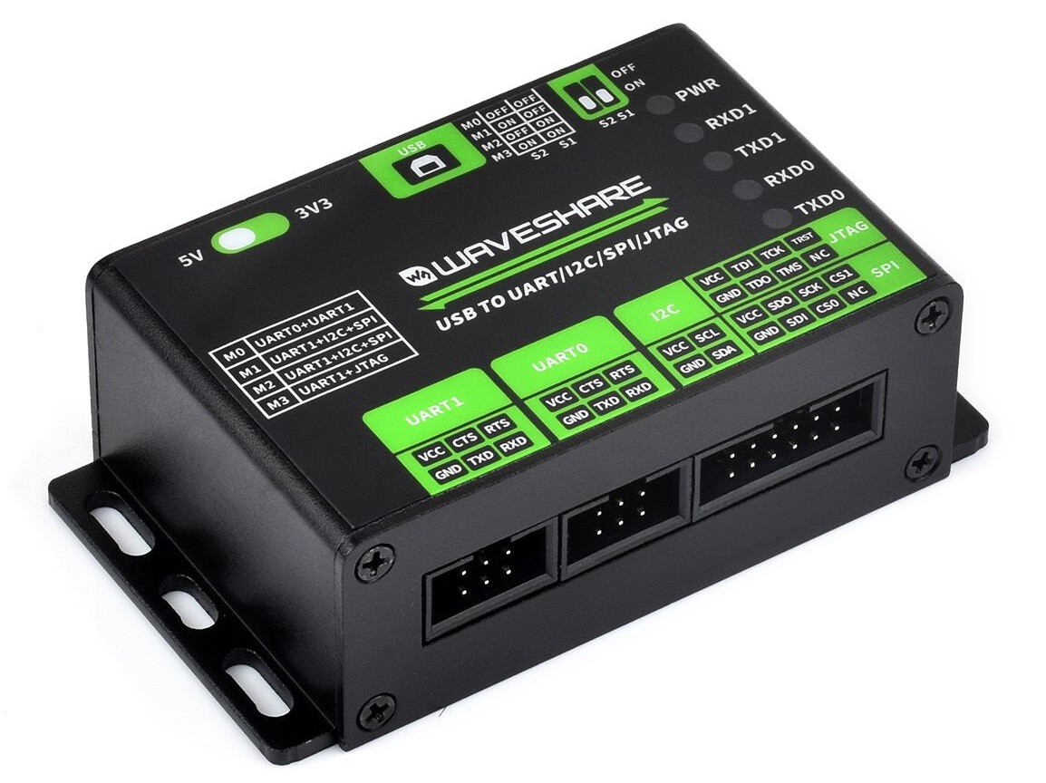
Complete NEWB to this. I have an ARM Cortex M4F, that I'm attempting to extract the firmware over JTAG with OpenOCD using a Waveshare USB TO UART/I2C/SPI/JTAG converter, and an Adafruit 0.05" POGO needle pin clamp.
Triple checked wiring, and it seems in order. Voltage set to 3.3V.
Using TDO, TDI, TRST, TCK, & TMS, as well as a ground.
Using JTAG ID code 0x4BA00477
Issue: JTAG isn't communicating, and receiving an error.
Any help or suggestions would be greatly appreciated.
For Reference:
https://www.waveshare.com/wiki/USB_TO_UART/I2C/SPI/JTAG#JTAG_Interface_Usage
https://fcc.report/FCC-ID/2AA72-PTR9618/3311432.pdf
https://www.st.com/resource/en/reference_manual/dm00031020-stm32f405-415-stm32f407-417-stm32f427-437-and-stm32f429-439-advanced-arm-based-32-bit-mcus-stmicroelectronics.pdf
https://documentation-service.arm.com/static/5ed643eaca06a95ce53f92aa
RM0090 Rev 21 1687/1757
RM0090 Debug support (DBG)
1716
The Arm ® Cortex ®
-M4 with FPU core provides integrated on-chip debug support. It is
comprised of:
• SWJ-DP: Serial wire / JTAG debug port
• AHP-AP: AHB access port
• ITM: Instrumentation trace macrocell
• FPB: Flash patch breakpoint
• DWT: Data watchpoint trigger
• TPUI: Trace port unit interface (available on larger packages, where the corresponding
pins are mapped)
• ETM: Embedded Trace Macrocell (available on larger packages, where the
corresponding pins are mapped)
It also includes debug features dedicated to the STM32F4xx:
• Flexible debug pinout assignment
• MCU debug box (support for low-power modes, control over peripheral clocks, etc.)
 buoyant jackal
sleek mountain
Complete NEWB to this. I have an ARM Cortex M4F, that I'm attempting to extract...
buoyant jackal
sleek mountain
Complete NEWB to this. I have an ARM Cortex M4F, that I'm attempting to extract...
On most microcontrollers, it is possible to lock access to the firmware so it can't be downloaded. I have no idea whether that's true here.
 neon pumice
I cut a USB micro B cable so I could hook it up to a AA size battery pack. the black internal wire doesn't have continuity with ground on the pi when I plug in the cable but the internal protective casing does have continuity...so I connected the ground of my battery pack to the protective casing...is that terrible or is that just how USB cables work? the Pi turns on and works just fine with this setup
latent lion
Did you check continuity on all 4 cores?
neon pumice
I checked if any other cores went to ground and none of them did
and the 5v core (red) has the correct continuity
latent lion
There’s usually 4 cores and 4 pins in a usb cable. Using the shroud in your application shouldn’t be an issue. But it is unusual that you’re not getting continuity on the ground pin with any of the cores
neon pumice
yeah it is weird. it's a $1 cable I picked up in a bin at a used electronics store though so maybe that's why
latent lion
Quite possibly. If you’ve got it working, it should be fine, it’s only a couple of AA batteries, not much energy stored in those
sleek mountain
neon pumice
I cut a USB micro B cable so I could hook it up to a AA size battery pack. the b...
It works, but is a bodge. I suggest finding another cable that isn't going to cause you reliability issues. A $10 tops cable is way cheaper than a new Raspi.
 elder glen
Hi all!
First I’d like to thank Adafruit for the very clear documentation and examples! I’m developing a hardware synthesizer on a Pi 5, and successfully managed to move the bulk of the code I was using from one library to another without any background in Python or programming (from gpiozero to adafruit_mcp3xxx)! I did run into a bit of a naming snag while trying to make some modifications, however.
It appears the naming convention for GPIO pin numbers used by the Adafruit examples follows CircuitPython, and I can’t seem to figure out how to determine which board pin numbers correspond to which GPIO pins. I searched through Discord and found this helpful video from John Park https://www.youtube.com/watch?v=x7-LASKwKjQ, but when I try to define the pin using “microcontroller.pin.GPIO8” instead of “board.D5”, I receive “NameError: ‘GPIO8’ is not defined” when I follow the same steps as in the video and import all the same modules. Is there something I need to do first or install for this to work correctly? I’d be happy to share any additional information and even the code itself if that would be helpful. Thank you for any suggestions!
gritty birch
elder glen
Hi all!
First I’d like to thank Adafruit for the very clear documentation and e...
can you provide a little more detail about what GPIO pins you're referencing? The ones on the Pi?
elder glen
gritty birch
can you provide a little more detail about what GPIO pins you're referencing? Th...
Sure thing! These are the pin numbers I'm referencing & used to seeing: https://pinout.xyz
The comprehensive add-on boards & GPIO Pinout guide for the Raspberry Pi
gritty birch
ok, well you're probably going to want to use RPi.GPIO: https://pypi.org/project/RPi.GPIO/
but if you can provide the code and the error message you are seeing, maybe someone can provide a more detailed suggestion
elder glen
gritty birch
ok, well you're probably going to want to use RPi.GPIO: https://pypi.org/project...
Thank you for the reply, I'm very much hoping to keep my code in adafruit_mcp3xxx. It's already working very well, I'm just struggling to make further modifications since I don't recognize the pin numbering system. I read several other libraries like gpiozero do not support more than one MCP3008, and I'm not sure whether RPi.GPIO supports this. Apparently the adafruit_mcp3xxx library should support more than one MCP3008, so this is why I moved my code from gpiozero to adafruit_mcp3xxx. I can definitely share the code if that will help.
 keen pasture
I need some help with my raspberry pi 5 using a adafruit triple bonnet for led matrix.
When I try to run the example code “simpletest” with the shapes, my screen appears like that (should be a play button but it is mixed up) I have tried flicking the address e switch on the bonnet multiple times but nothing changes. My screen is a P4 screen.
 elder glen
gritty birch
but if you can provide the code and the error message you are seeing, maybe some...
elder glen
gritty birch
but if you can provide the code and the error message you are seeing, maybe some...
This is the code I'm using, copied below. If I use board.D5 instead of microcontroller.pin.GPIO8 then everything works fine, but I'm trying to make modifications and therefore need to use the GPIO numbers I'm familiar with since I don't know which physical pin on the Pi that board.D4, board.D6, etc would be. The microcontroller.pin naming convention was borrowed from John Park's youtube video I linked above, but when I try to use microcontroller.pin.GPIO8 I receive the error “NameError: ‘GPIO8’ is not defined”.
elder glen
elder glen
This is the code I'm using, copied below. If I use **board.D5** instead of **mic...
white marsh
elder glen
This is the code I'm using, copied below. If I use **board.D5** instead of **mic...
No experience running this on Pis but this page's examples https://learn.adafruit.com/circuitpython-on-raspberrypi-linux/digital-i-o would seem to imply that GPIOx = Dx so on that page they used GPIO18 which is D18. So for your GPIO8 have you simply tried D8?

Make hardware and interface with sensors super easy using CircuitPython libraries
elder glen
white marsh
No experience running this on Pis but this page's examples https://learn.adafrui...
Thank you for your reply! In this case, I know board.D5 is referencing the GPIO 8 pin for sure because I already have the cs pin from the MCP3008 plugged into GPIO 8 with everything reading correctly, with the code referencing board.D5. As you pointed out with that post, it seems sometimes the numbers may correlate and often they do not.
white marsh
elder glen
Thank you for your reply! In this case, I know board.D5 is referencing the GPIO ...
Ah I see. I assume you are running Blinka, so since it is not actual CircuitPython not sure if this will work, but with an MCU board this code will show you all the pin definitions...
# Show the information of the microcontroller
import board
import wifi
import microcontroller

if True:  # show Pin Assignments. Change to False to not run this part
    print ("\nMCU board is a", board.board_id, "connected to", wifi.radio.ipv4_address)
    print("\n\tMicrocontroller Pin Assignments:")
    board_pins = []
    for pin in dir(microcontroller.pin):
        if isinstance(getattr(microcontroller.pin, pin), microcontroller.Pin):
            pins = []
            for alias in dir(board):
                if getattr(board, alias) is getattr(microcontroller.pin, pin):
                    pins.append("board.{}".format(alias))
            if len(pins) > 0:
                board_pins.append(" ".join(pins))
    for pins in sorted(board_pins):
        print(pins)
    print("\n>>> dir(board)")
    print(dir(board))
    print('\n>>> help("modules")')
    print(help("modules"))
Although I suspect it may not work with Blinka. But doesn't hurt to give it a try.
elder glen
white marsh
Ah I see. I assume you are running Blinka, so since it is not actual CircuitPyth...
I will give it a shot, thank you very much!
I am indeed running Blinka, it's telling me there's no module named "wifi" when I try to run the code. Ironically I am connecting to it via ssh over wifi
white marsh
Oh yeah, just delete that import wifi and the first line in the loop or at least the wifi.radio... part
e.g. print ("\nMCU board is a", board.board_id, "connected to", wifi.radio.ipv4_address)
becomes
print ("\nMCU board is a", board.board_id)
elder glen
Hey it did something! 🎉
white marsh
But did it do something useful? 😃
elder glen
It looks like it printed the output of all the pins, so I think this was massively helpful! I think I just need to figure out how the order correlates to the GPIO pin order, but I think this is exactly what I needed so I can continue using board.Dx pin definitions without error!
white marsh
elder glen
Hmmm, for some reason I was thinking it also put out the GPIO numbers. Hold on, I may have given you older code before I figured out how to add GPIO numbers.
Ah here we go...
# Show the information of the microcontroller
import board
import microcontroller

print("\nMCU board is a", board.board_id)
print("\n\tMicrocontroller Pin Assignments:")
board_pins = []
for pin in dir(microcontroller.pin):
    if isinstance(getattr(microcontroller.pin, pin), microcontroller.Pin):
        pins = []
        for alias in dir(board):
            if getattr(board, alias) is getattr(microcontroller.pin, pin):
                pins.append("board.{}".format(alias))
        if len(pins) > 0:
            pins.append(f"({str(pin)})")
            board_pins.append(" ".join(pins))
for pins in sorted(board_pins):
    print(pins)
print("\n>>> dir(board)")
print(dir(board))
print('\n>>> help("modules")')
print(help("modules"))
with Wifi stuff removed.
The first code goes through the GPIO pin numbers but doesn't print them. The second code adds the pins.append(f"({str(pin)})") bit to add the GPIO in parens at the end of each line of pin definitions.
elder glen
Looks like it's pretty much 1-to-1 as you suggested, but then how does board.D5 = GPIO 8 = pin 24 if that's the case?
white marsh
Dang! Must be because it is a Pi running blinka and not an actual microcontroller running CircuitPython.
elder glen
All good, I still really appreciate the support! I could always back up the micro SD card and install CircuitPython to get the pin numbers, then restore the micro SD image if that's going to be the best way to get the info.
white marsh
For reference when I run that code with a Qt Py boards I get
    Microcontroller Pin Assignments:
board.A0 board.D18 (GPIO18)
board.A1 board.D17 (GPIO17)
board.A2 board.D9 (GPIO9)
board.A3 board.D8 (GPIO8)
board.A4 board.D7 board.SDA (GPIO7)
board.A5 board.D6 board.SCL (GPIO6)
board.A6 board.D5 board.TX (GPIO5)
board.A7 board.D16 board.RX (GPIO16)
board.BUTTON board.D0 (GPIO0)
board.D35 board.MOSI (GPIO35)
board.D36 board.SCK (GPIO36)
board.D37 board.MISO (GPIO37)
board.D40 board.SCL1 (GPIO40)
board.D41 board.SDA1 (GPIO41)
board.NEOPIXEL (GPIO39)
board.NEOPIXEL_POWER (GPIO38)
Just a thought, but you said that you have your CS plugged into D8 and the code is referencing D5. Could it be that D8 is just always high and so the CS is always asserted and always works? You can test it by plugging your CS line into Vcc and see if the code still works with a constant (instead of controlled) CS. If it works try plugging into a different GPIO pin and see if it still works. If it still does, then you may have simply fooled yourself and GPIOx does = Dx.
elder glen
white marsh
Just a thought, but you said that you have your CS plugged into D8 and the code ...
I think you're probably onto something here. I have the hardware attached according to these instructions https://github.com/lysdexic-audio/RNBO-RPi-Pots, and when I moved to the adafruit_mcpxxx library everything works just fine using the same connections. So it's possible I'm just assuming GPIO 8 = board.D5 since I hadn't changed the wiring and it works. I can try your test, but I am struggling to determine which pin is Vcc as I am relatively new to this.
white marsh
Well just try another GPIO pin and if it works you know the code isn't talking to both pins.
elder glen
white marsh
Well just try another GPIO pin and if it works you know the code isn't talking t...
If I plug the cs line from the MCP3008 into GPIO25 instead of GPIO8, then the script reads everything as 0 and the potentiometers / MCP3008 don't respond. This is with the code referencing cs as board.D5.
Oh but wait! If I specify board.D25 while plugged into GPIO25 then it works again! This makes me think the regular / green GPIO pins on the pinout chart here https://pinout.xyz are in fact 1-to-1 as you suggested, and maybe some other pins don't correlate such as the SPI pin numbers.
Okay well in that case, for now I think I have what I need to make the necessary modifications to add another MCP3008 to the wiring & code! Thank you for all your support and time! 🎉
elder glen
keen pasture
I need some help with my raspberry pi 5 using a adafruit triple bonnet for led m...
Best of luck with your LED matrix project! Bumping since I stole the thread for a bit there.
 pure elm
Hi AdaPeople! I've hit a new need for my little Adafruit ESP32-S3 Reverse TFT Feather - I'd like to connect it to a Linux PC using only it's GPIO pins...
Basically, I'm looking to be able to communicate small strings of data (temp/humidity are first things, short strings), over to a common PC, like featherboard --><gpio>--> PC - (end result, trying to get telemetry output to a file, easy on the UNIX side...
Has anyone here done this, or know any approaches to doing it?
(note: I cannot use the USBc or Wifi on the featherboard for connectivity, they're already in use)
Any thoughts/ideas are most welcome!!!

 fleet terrace
pure elm
Hi AdaPeople! I've hit a new need for my little [Adafruit ESP32-S3 Reverse TFT ...
fleet terrace
pure elm
Hi AdaPeople! I've hit a new need for my little [Adafruit ESP32-S3 Reverse TFT ...
If it has a serial port, you can use UART on the Feather.
pure elm
hrm TBH I'm not sure the PC I'm using has a classic 9-pin serial port, but I do have USB ports and USBc...
hrm
fleet terrace
USB-to-Serial will work
It is what all boards without a USB-native microcontroller do
pure elm
oh, like this? (the price is right for me), https://www.adafruit.com/product/5335
fleet terrace
yes
pure elm
bingo- I'll try it- thanks so much @fleet terrace !
 last orchid
Allo. I am on a very tight budget, and would like to build an LED video wall, since my only way of making money right now is DJing, and livestreaming.
Oh I guess photography and videography as well - but that's irrelevant.
Since these modular LED walls are extremely expensive, I would like to make my own. I am thinking of getting custom PCBs made. Not sure where I should start though. Maybe I should whip out one of my little LED grids and try to get that working
molten iris
last orchid
Allo. I am on a very tight budget, and would like to build an LED video wall, si...
It's currently out of stock, but check out the rp2040 Scorpio if you're on a budget - it can drive a ton of LED strips
molten iris
No, I don't think so
fleet terrace
last orchid
Since these modular LED walls are extremely expensive, I would like to make my o...
You're not going to make large custom LED matrixes less expensive than existing panels like these: https://www.adafruit.com/product/5362
last orchid
fleet terrace
You're not going to make large custom LED matrixes less expensive than existing ...
wow that's a nice price for the size
it might be way easier just to buy like 4 TVs and call it a day
not the same effect though
 slim geyser
Hello, I have this parts list, basically wanting to make a lightbox that has an rgb led that i can program to do different colors and stuff, is there anything else I would need, or anything I should change? any help is appreciated

 coral urchin
slim geyser
Hello, I have this parts list, basically wanting to make a lightbox that has an ...
coral urchin
slim geyser
Hello, I have this parts list, basically wanting to make a lightbox that has an ...
the pages for the backlight display and illuminated pushbutton both say that you'll need resistors for them
slim geyser
coral urchin
the pages for the backlight display and illuminated pushbutton both say that you...
ok got it
 subtle walrus
anyone interested in taking a look at my schematic? I'm relatively a beginner and just trying to figure stuff out
fleet terrace
subtle walrus
anyone interested in taking a look at my schematic? I'm relatively a beginner an...
Most people are probably willing to help. But cross-posting questions is not appreciated by almost everyone.
subtle walrus
fleet terrace
Most people are probably willing to help. But cross-posting questions is not app...
I understand. I just wasn't sure which chat to post in, I'll leave this one up and remove any other I might have posted
slim geyser
updated item list, is there any other things that I would need or anything that will not work together?
 fleet terrace
subtle walrus
I understand. I just wasn't sure which chat to post in, I'll leave this one up a...
fleet terrace
subtle walrus
I understand. I just wasn't sure which chat to post in, I'll leave this one up a...
(also, share your scheamtic... 😃 )
fleet terrace
slim geyser
updated item list, is there any other things that I would need or anything that ...
If you have zero components, I would suggest some 10 uF capacitors: https://www.adafruit.com/product/2195. You may not need them, but you'll be glad if you do.
Also, do you have soldering equipment and supplies?
subtle walrus
fleet terrace
(also, share your scheamtic... 😃 )
I think my error is getting pin I0 and pin I1 confused, I want it to be in SPI mode but I think I set the wrong pins to high and low. page 48 displays the pinout for the PN532 chip

 muted fable
Can someone help me figure out how to wire this together for PS5? I have a USB hub with a magicboots and an adafruit feather RP2040 with usb a type host
 slim geyser
fleet terrace
If you have zero components, I would suggest some 10 uF capacitors: <https://www...
slim geyser
fleet terrace
If you have zero components, I would suggest some 10 uF capacitors: <https://www...
I do have soldering equipment, also what would the capacitors be used for?
 inland bough
Hey I am having issues getting my battery tester to work properly using the lm3914 IC.
Here are my problems :
- Currently in bar mode(mode pin wired to vcc) all the leds turn on despite the battery being at 12.51 volt (I am using a 12.6v li-ion battery
- in dot mode (mode pin wired to ground) the led 9 turns on AND the led1 which is wrong as there should only be one
I also had this issue with a lm3914 soldering kit which I brushed off as my personal error while soldering but now I'm starting to wonder if it's my battery? I'm not sure as I tried with a 3v battery and I still see the red led turning along another one.
On the left of the breadboard is a voltage divider with the 3 resistors in series doing 1.8kohms with 200ohms on the right so it converts 12.6 down to 1.26 or somewhere around that.
on the right there are 3 resistors in series doing 1.2k ohms
I'm very sorry if I'm doing something wrong I am very new to electronics and learn new things every day


 marsh bridge
subtle walrus
I think my error is getting pin I0 and pin I1 confused, I want it to be in SPI m...
marsh bridge
subtle walrus
I think my error is getting pin I0 and pin I1 confused, I want it to be in SPI m...
Need a higher quality image of the schematic to read it clearly [e.g. PNG or jpeg with higher quality, or a PDF etc].
Apologies if it was just my phone being uncooperative.
 topaz verge
Hi everyone, I have an ESP32-S3 super mini and i am trying to make it appear as an audio device on my windows PC but following the intructions from this github: https://github.com/espressif/esp-iot-solution/tree/master/examples/usb/device/usb_uac does not work for me. I get to the last step and I cannot load the example onto my chip. I would greatly appreciate help from anyone as I'm slamming my head trying to get this to work
Edit: IDE is VSCode with ESP-IDF

GitHub
Espressif IoT Library. IoT Device Drivers, Documentations and Solutions. - espressif/esp-iot-solution
marsh bridge
Have you tried flashing the bin with esptool instead of using idf.py flash? Also, including the error log from your flash attempt would be great.
I did hear of some issues with their plugin that said if upload/build buttons fail just run idf commands in terminal
 digital fossil
hey so when i try to acsess this page in the feather esp32-s2 guide it takes me to a blank page that just says forbidden https://learn.adafruit.com/adafruit-esp32-s2-feather/power-management

Make your IoT project fly!
i kinda need access to this page for a project if it exists
if not i would like some info on how i would add wireless charging to the feather because im using its integrated battery charging and i wznt to use those same protections with wireless charging
now its the whole learn quide
ok the shop works but the guid is down or something?
 vocal radish
Loads fine for me
vocal radish
I clicked on the link, it loaded
digital fossil
digital fossil
if not i would like some info on how i would add wireless charging to the feathe...
back to my main question now
is there any regulation on the usb input on the feather? like it it expecting 5v or is it just taking whatever?
buoyant jackal
digital fossil
back to my main question now
It is taking the voltage from the USB jack, and assumes it is 5V. The "USB" pin on the board is connected directly to that. There is a regulator from that voltage to 3.3V to power the board circuitry.
The battery charging circuitry is separate and charges the battery via the battery jack (or BAT) pin when connected to USB.
digital fossil
buoyant jackal
It is taking the voltage from the USB jack, and assumes it is 5V. The "USB" pin ...
thank you for the clarification
digital fossil
buoyant jackal
It is taking the voltage from the USB jack, and assumes it is 5V. The "USB" pin ...
the usb pin is directly connected to the usb jack correct? So i can charge the battery by powering the usb pin with 5v?
obviously i wouldnt do that and have it plugged into anything else with the jack
buoyant jackal
digital fossil
the usb pin is directly connected to the usb jack correct? So i can charge the b...
yes, BUT make sure it's not also connected to, say, a computer. Otherwise you will back-power the connected computer and could damage its USB port. Consider plugging the 5V supply into the USB jack to avoid this danger
digital fossil
buoyant jackal
yes, BUT make sure it's not also connected to, say, a computer. Otherwise you wi...
im trying to add wireless charging so that is not an option unfortunatly
with these (i need smaller ones then adafruit has) https://www.amazon.com/Wireless-Charger-Transmitter-Module-Output/dp/B08N6VN337

Wireless Charging Power Supply Module Inductive Charger
Main parameters of the module:
Input voltage: 5V~12V;
Transmitter module Dimensions: Length 21mm * wide 10 mm * 2.2mm high;
Transmitting coil: outer diameter 12.7mm, inductance 3.9uH;
Receiver Module dimensions: length 24mm * widt...
basically im making sonic screwdriver so it's something that shouldnt be plugged in normally at all, except for like debugging
I also got confirmation from one of the adafruit peeps that this should work but i just have to be careful about back powering it which should not be a problem because i take the battery out to test it anyways
buoyant jackal
digital fossil
with these (i need smaller ones then adafruit has) https://www.amazon.com/Wirele...
you could also add a diode
digital fossil
buoyant jackal
you could also add a diode
oh for backfeed protection?
buoyant jackal
digital fossil
oh for backfeed protection?
yes, for backfeed prevention to the module above. You would want to use a Schottky diode for low voltage-drop reasons.
topaz verge
marsh bridge
Have you tried flashing the bin with esptool instead of using `idf.py flash`? Al...
sorry for the stupid question, beginner with these tools, i did download EIM, but how would i flash this? let me see how to get the error log VSCode.
 zealous harness
I’m building a TV-head cosplay (in the style of the Minbit tutorial) and I’m stuck on what looks like a fundamental addressing / scan-rate issue with my LED matrix setup. Hardware: Adafruit MatrixPortal S3 connected to an RGB full-color HUB75 LED matrix panel that is sold as a 64×32, 4mm pitch, 1/32 scan panel: https://eckstein-shop.de/RGB-Full-Color-LED-Matrix-Panel-64x32-4mm-Pitch-1-32-Scan?ws_oss_lieferland=CH
What I’m trying to do: drive the panel as a “screen” for animations/images. I’ve tested a lot of different code (Minbit’s code, other community examples, and my own CircuitPython attempts) and I consistently can’t address the full display correctly when I set the expected dimensions.
Symptoms / what’s going wrong
-
If I configure the display as 64 width × 32 height, I can’t properly access all pixels. In practice I usually only get the lower half behaving correctly.
-
It looks like there is a vertical offset of about 16 pixels (as if the mapping starts halfway down or rows are being selected incorrectly).
-
If I “cheat” and set the height to 64 (even though the panel is physically 32 high), the content shifts upward, which makes it look like the software thinks it’s driving a 64×64 surface, so images and coordinates don’t match reality and loading bitmaps properly becomes a mess.
End result: I can’t reliably load or position images because the logical coordinate system doesn’t match the physical panel.
What I’ve already tried
-
Minbit tutorial code and wiring assumptions
-
Multiple other people’s examples (various libraries/configs)
-
My own tests focused on drawing simple patterns to corners/edges to verify mapping
-
Different width/height settings, including forcing 64×64 to observe behavior shifts
Nothing has produced correct full-height addressing on a real 64×32 canvas.
What I suspect / why I’m posting
I’m not sure this is a normal “software bug” anymore. I’m starting to suspect the panel’s scan configuration (advertised as 1/32 scan) is the root cause and that my stack/library/controller setup is effectively treating it like a different scan type (or missing an address line). It behaves like row addressing isn’t selecting the correct row groups, which would explain:
-
only half the rows responding,
-
the apparent ~16px offset,
-
the weird “it kind of works if I pretend it’s taller” effect.
Questions for anyone who has worked with MatrixPortal S3 + HUB75 panels
-
Has anyone successfully driven a 64×32 panel labeled 1/32 scan with a MatrixPortal S3? If yes, what library/configuration made it work?
-
Is there a known requirement for extra row address lines (e.g., an “E” address line or HUB75E-style mapping) when dealing with certain 1/32 scan panels, and does the MatrixPortal S3 + CircuitPython stack support that cleanly?
-
Could the panel be mis-sold / mis-labeled (e.g., actually a different scan type), and if so, what’s the quickest way to verify the real scan rate or row- multiplexing behavior?
For example: markings on the back, driver IC model numbers, typical scan patterns for 64×32, etc.
If this is a mapping issue rather than the scan rate itself: are there known “row swap / row order / panel variant” settings for this kind of panel that would explain a consistent 16px offset?

ListenVision RGB Full-Color LED Matrix Panel 64x32 4mm Pitch 1/32 Sca, 19,94 €
Entdecken Sie bei Eckstein Komponente eine Vielzahl an Elektronikprodukten – von epaper eink displays bis hin zu Entwicklungsbrettern wie Raspberry Pi und A
full prism
Have you tried wled-mm on the matrix portal?
The stained glass project on the Learn section is a good guide if you're not familiar with wled / moon modules, and it should at least help you determine if the panels are broken
 sturdy depot
So I have this battery hat for the pi zero with a built in on/off switch but I am putting it into a 3D printed NES controller case and I need to wire an external on/off switch in a different slot on the case


How would I wire that up?
The switch has 2 metal pins while the on/off on the battery hat has 5
I also can’t find the labels on the switch pins
So I don’t know what pin goes to what
gritty birch
You could contact the manufacturer and ask: https://seengreat.com/product/322/uninterruptible-power-supply-with-battery-monitoring-5v-1-8a-output-fo?srsltid=AfmBOoqfPmNOxh_i__xK4TennxpmwY-UE2HdgFFt98Z-kxUFp7lJoqq4 they even have an AI chatbot ready to help!
 upper bloom
sturdy depot
The switch has 2 metal pins while the on/off on the battery hat has 5
upper bloom
sturdy depot
The switch has 2 metal pins while the on/off on the battery hat has 5
Of the 5 pins on the switch, the outer 2 pins are the mounting pins, and the center pin is your COMmon. The pin by the OFF position should be OFF and the one by the ON position should be ON.
To wire your own 2-pin switch externally, either desolder the switch or leave it in the off position, then attach wires from your switch to the COM and ON pins.
 wet bison
sturdy depot
So I have this battery hat for the pi zero with a built in on/off switch but I a...
wet bison
sturdy depot
So I have this battery hat for the pi zero with a built in on/off switch but I a...
So to add to Hem. Outer 2 pins are mounting pins and they are useless. Center pin should be the pole. Pins 2 and 4 should be the throw. Looks like single pole double throw. Basically the switch works by connecting the throw to one of the poles. You need to find out if the “off” selection is actually used for anything. If off just left floating you can use your switch. If the off selection is using logic you will need a single-pole double throw to replace.
Sorry if that is confusing. Just put it into chatgpt if you don’t understand me.
This image may be confusing but this is how it works.

 ebon apex
is there a way to use my ESP-S3 Rev TFT Feather with Microblocks?
 swift cloud
ebon apex
is there a way to use my `ESP-S3 Rev TFT Feather` with **Microblocks**?
swift cloud
ebon apex
is there a way to use my `ESP-S3 Rev TFT Feather` with **Microblocks**?
Yes. Turn on advanced mode, then click install ESP firmware from microblocks.fun, then select esp32-s3.
ebon apex
swift cloud
Yes. Turn on advanced mode, then click install ESP firmware from microblocks.fun...
testing, i thought advanced mode was on, but i guess its not
ebon apex
swift cloud
Yes. Turn on advanced mode, then click install ESP firmware from microblocks.fun...
when i try to press ▶️ it always gives me the error "board not connected" but
it shows as connected

 swift cloud
ebon apex
when i try to press ▶️ it always gives me the error "board not connected" but
swift cloud
ebon apex
when i try to press ▶️ it always gives me the error "board not connected" but
How did you try to connect it?
ebon apex
swift cloud
How did you try to connect it?
the connect button
-# i may be misunderstanding
swift cloud
ebon apex
the connect button
-# i may be misunderstanding
It uses UF2s, not the standard firmware on most ESP32s (.bin)
ebon apex
swift cloud
It uses UF2s, not the standard firmware on most ESP32s (.bin)
wdym
do i install circuitpython?
swift cloud
ebon apex
wdym
On my ESP32 (not the S3), it uses binaries (.bin files) as firmware. However the ESP32-S3 uses UF2 files as firmware, which are more common.
CircuitPython and Arduino are probably the only things you can do.
ebon apex
swift cloud
On my ESP32 (not the S3), it uses binaries (.bin files) as firmware. However the...
so microblocks is not usable?
swift cloud
ebon apex
so microblocks is not usable?
Not on that board. Other ESP32-S3 boards that are not Adafruit can use it.
ebon apex
swift cloud
Not on that board. Other ESP32-S3 boards that are not Adafruit can use it.
ok
do you know of any blockcode options that work with my one?
swift cloud
ebon apex
ok
do you know of any blockcode options that work with my one?
Adafruit IO Actions uses block code.
If you want to do MicroBlocks you will have to flash the ESP32 bootloader
ebon apex
swift cloud
Adafruit IO Actions uses block code.
If you want to do MicroBlocks you will have...
wdym by flash the bootloader?
ebon apex
swift cloud
Adafruit IO Actions uses block code.
If you want to do MicroBlocks you will have...
is that the "install firmware"?
swift cloud
ebon apex
is that the "install firmware"?
No, the bootloader is different. The bootloader makes the ESP32 accept certain files as code
ebon apex
swift cloud
No, the bootloader is different. The bootloader makes the ESP32 accept certain f...
how can i do that?
swift cloud
ebon apex
how can i do that?
ebon apex
swift cloud
https://docs.espressif.com/projects/esp-idf/en/stable/esp32/api-guides/bootloade...
do i want to follow https://docs.espressif.com/projects/esp-idf/en/v5.5.2/esp32s3/api-guides/bootloader.html instead?
ebon apex
swift cloud
https://docs.espressif.com/projects/esp-idf/en/stable/esp32/api-guides/bootloade...
i cant really work out what the page wants me to do, sorry
what do i flash the bootloader with?
swift cloud
ebon apex
what do i flash the bootloader with?
esptool. Run pip install esptool in a Python venv or in Command Prompt.
ebon apex
swift cloud
esptool. Run pip install esptool in a Python venv or in Command Prompt.
can i use https://adafruit.github.io/Adafruit_WebSerial_ESPTool/ ?
what do i flash it with?
swift cloud
ebon apex
can i use https://adafruit.github.io/Adafruit_WebSerial_ESPTool/ ?
what do i fla...
Yes
ebon apex
swift cloud
Yes
and what do i flash it with, i couldn't understand anything in https://docs.espressif.com/projects/esp-idf/en/stable/esp32/api-guides/bootloader.html
swift cloud
ebon apex
and what do i flash it with, i couldn't understand anything in https://docs.espr...
All you need is bootloader.bin it should be in that website
ebon apex
swift cloud
All you need is bootloader.bin it should be in that website
do i use the one for esp32 or esp32-s3?
swift cloud
ebon apex
do i use the one for esp32 or esp32-s3?
esp32-s3 (if there is also a esp32-s3-mini option try that)
ebon apex
swift cloud
esp32-s3 (if there is also a esp32-s3-mini option try that)
is s3-mini or just s3 better?
ebon apex
swift cloud
All you need is bootloader.bin it should be in that website
cant find boot.bin
ebon apex
swift cloud
esp32-s3 (if there is also a esp32-s3-mini option try that)
would i want to use vm_esp32-s3.bin from https://microblocks.fun/downloads/latest/vm/ or is that something other than a bootloader?
buoyant jackal
you can probably use that. I'm not that familiar with Microblocks. You don't need a separate bootloader. You put the board into ROM bootloader mode. Hold down the BOOT button and press RESET.
maybe Microblocks has a loader too. You need to use a Chrome-based browser
ebon apex
buoyant jackal
You can use https://adafruit.github.io/Adafruit_WebSerial_ESPTool/ or https://es...
im using adafruit web serial tool, do you have any idea what the problem im getting with microblocks is?
buoyant jackal
The .bin is a generic one for ESP32-S3, and I don't know how it's going to work on your Reverse Feather S3. It's not going to make the display work or anythiing like that, and probably not even the NeoPixel.
buoyant jackal
ebon apex
im using adafruit web serial tool, do you have any idea what the problem im gett...
there are a lot of posts here, I'm not sure what your problem is.
make sure you don't have a terminal program or other browser tabs open that are using that serial port.
ebon apex
buoyant jackal
make sure you don't have a terminal program or other browser tabs open that are ...
i am able to upload the firmware from microblocks onto the feather but even when its connected to microblocks it claims to not be connected when i attempt to run code on it
buoyant jackal
the firmware may not be working after you load it. Do you have any other microcontroller boards, like a Pi Pico?
what is your host computer?
ebon apex
buoyant jackal
the firmware may not be working after you load it. Do you have any other microco...
i have a few pi picos, some arduino unos an arduino nano and 2 qt-py 2040s
buoyant jackal
why don't you try a pi pico first, which is easy to load and we know the firmware is specifically for that board.
or have you already done that?
ebon apex
buoyant jackal
what is your host computer?
mac mini m2, os Version 26.3 Beta but i can use a family mebers winows 11 pc
buoyant jackal
mac mini should be fine
ebon apex
buoyant jackal
why don't you try a pi pico first, which is easy to load and we know the firmwar...
will try
ebon apex
buoyant jackal
or have you already done that?
no
ebon apex
buoyant jackal
mac mini should be fine
im not using online microblocks but the app btw
ebon apex
buoyant jackal
why don't you try a pi pico first, which is easy to load and we know the firmwar...
worked with pi pico w
buoyant jackal
if that's good enough for your purposes now, I'd just stick with that. There are various variations of ESP32-S3 wrt PSRAM size, flash size, etc, and why it doesn't work could take a while to track down. If Microblocks has its own support forum or discord, that would be a place to ask.
ebon apex
buoyant jackal
if that's good enough for your purposes now, I'd just stick with that. There are...
i was intending to use the tft on the feather, i also wanted to use the cardkb.
buoyant jackal
My impression is that Microblocks doesn't know enough about the Feather to use the display. You would want to use CircuitPython.
ebon apex
buoyant jackal
My impression is that Microblocks doesn't know enough about the Feather to use t...
i cant use circuitpython as i cant code, although i would love to, i do not have enough time/energy to learn to code at an advanced enough level.
i was unable to find any way of using circuitpython in a non-text-based way.
buoyant jackal
There is edublocks.org, and also we have a brand new blocks capability for wippersnapper, which is IoT-oriented. There is some display support in wippersnapper
https://learn.adafruit.com/how-to-use-blockly-for-actions-on-adafruit-io. There are many Adafruit IO guides
ebon apex
buoyant jackal
There is edublocks.org, and also we have a brand new blocks capability for wippe...
i dont think its possible to use a cardkb or other non-iot things with adafruitIO
buoyant jackal
Eventually you will need to learn some coding. Edublocks et al can help you relate the blocks puzzle pieces to programming language syntax. It is not that hard to learn.
if you are using blocks are ARE coding, just not with plain text.
makecode is another possibility
ebon apex
buoyant jackal
makecode is another possibility
i dont think makecode supports tft feather
 frank minnow
Hi. I've got a weird issue with my project code.
The project is a NRF52840 based wireless mouse with an PMW3389 sensor. In the code Ive got this debugLED(int ledNumber, RGBColor color, bool flash, bool loop) function, that gets called like this debugLED(0, {255, 0, 0}, false); by various functions throughout the code. Additionally it gets called with loop = true by the main loop of the code, to process the flashing timers. All LEDDebugs can be disabled by setting the doLEDDebug bool to false.
My issue is, that when i set doLEDDebug to false at the start or during runtime the core runs significantly slower than when its true (noticable because the cursor moves segnificantly slower).
I cant really figure out why, if anything it should run faster when doLEDDebug is disabled, since it skips all the led processing stuff, but its the exact opposite.
Here is the debugLED function:
void debugLED(int ledNumber, RGBColor color, bool flash, bool loop)
{
    if (doLEDDebug)
    {
        if (loop)
        {
            for (int i = 0; i < 6; i++)
            {
                if (millis() - ledFlashCounter[i] >= ledFlashDuration && ledFlashCounter[i] != 0)
                {
                    led.setPixelColor(i, 0, 0, 0);
                    ledFlashCounter[i] = 0;
                }
            }
            led.show();
        }
        else
        {
            led.setPixelColor(ledNumber, led.Color(color.r, color.g, color.b));
            led.show();
            if (flash)
            {
                ledFlashCounter[ledNumber] = millis();
            }
        }
    }
}```oh also i should give a little VibeCoding warning 🙂
buoyant jackal
ebon apex
i dont think makecode supports tft feather
no, you'd have to choose something else. MakeCodes supports various boards with displays via its game support: https://arcade.makecode.com/hardware
ebon apex
buoyant jackal
no, you'd have to choose something else. MakeCodes supports various boards with ...
i managed to get a microblocks connection with my feather with extremely limited functionality by using a vm/firmware for a different board, so it can connect. i am going to try and get ChatGPT to help me.make a compatible firmware
buoyant jackal
ebon apex
i managed to get a microblocks connection with my feather with extremely limited...
you would have to set up a build environment for the board. This may end up being a rathole. It's worth going up a few levels to see what would meet your needs. What is your goal with the the display on the board and the separate keyboard?
I'm looking at the Microblocks wiki and the board support info. The only display support I see ifs for monochrome OLED displays, such as the Adafruit CLUE. I don't see support for a color TFT display.
 unborn grotto
i wanted to try my luck here and ask for a bit of advice as someone unfamiliar with this kinda stuff, but im working on a cosplay project and noticed im having issues with my 64x64 3mm pitch led matrix having a split screen? (using a matrixportalm4) i soldered the bridges between e8 hoping itd work so i'm not sure what i should do here :(


heres the code i used for it too,, i can show the circuitpy folder when i get back from work if its needed
fleet terrace
unborn grotto
i wanted to try my luck here and ask for a bit of advice as someone unfamiliar w...
make a simple 64x64 bitmap and simple code to load just that. Then you can verify if the controller is able to address the entire matrix.
unborn grotto
i'll see if i can make one and update tomorrow when i get home 🙏
 lethal prairie
Hi folks. Hoping for some advice on a small (~2") display & microcontroller combo to add to an artistic project. Looking for high frame rate (>50fps), color, preferably IPS for good viewing angle. Browsing the shop it was hard to determine maximum frame rates or controller requirements. Actual rendering I don't anticipate to be resource-intensive. Nice to have: display on a ribbon cable so I can hide the rest
warm jay
Got another problem:
I am using some flexible LED filament.
12V 300mm length.
When I connect it to a power supply it tries to draw a lot of current (over 900 mA) and starts to smoke.
What component do I need to reduce the current? If I just use a resistor it will probably also reduce the voltage and that would mean it does not turn on?
south ledge
warm jay
Got another problem:
I am using some flexible LED filament.
12V 300mm length.
...

Flexible LED Noodles
warm jay
thanks that should be helpful yes
and one more question for another LED strip.
12V COB LED strip 6500K 5m
480 LEDs/m
I put it on a bench power supply at 12V.
It reads 0.835 A
Is that "OKAY" for such an LED strip? Or should it be more?
it seems a bit low for 5 meters?
coral urchin
warm jay
Is that "OKAY" for such an LED strip? Or should it be more?
is it bright enough? if so, it's good enough
and yes, LEDs always need a resistor. the only time you don't need to use one is when the LED already has one built in
white marsh
coral urchin
and yes, LEDs always need a resistor. the only time you don't need to use one is...
or when using a constant current supply.
warm jay
coral urchin
and yes, LEDs always need a resistor. the only time you don't need to use one is...
Any LED strip? I got one from amazon but it did not specify if it has a resistor build in. Just +12V and GND with red and black wire
buoyant jackal
warm jay
Any LED strip? I got one from amazon but it did not specify if it has a resistor...
Those have built-in resistors. Bare LED's need resistors.
warm jay
So those LED filaments are considered bare LEDs then?
buoyant jackal
warm jay
So those LED filaments are considered bare LEDs then?
not usually. Could you give a URL for the product? Sounds like it might be being wired backwards. Usually 12V strips can be driven with any 12V supply. No current limiting should be necessary.
usually the LEDs are in groups of 3 or 4 so you don't need a resistor on each one
 rancid merlin
is the bno055 stemma qt compatible with esp32? I have been searching all over google for answers and youtube. I have seen success and failure stories. I need a clear answer, is the bosch bno055 compatible with esp32 devkitc 32e despite the clock stretching issues listed in the documentation? will connecting the 3v3 to the sda and scl while adding 2 pull up resistors of 4k7 ohms each to the sda and scl solve this? Please help I beg
buoyant jackal
rancid merlin
is the bno055 stemma qt compatible with esp32? I have been searching all over go...
what sw are you using with it? There were some fixes with ESP-IDF 5.3.2 that improved things. I think someone also suggested unequal pull-up resistors.
will connecting the 3v3 to the sda and scl while adding 2 pull up resistors of 4k7 ohms each to the sda and scl solve this?
Do you mean connecting directly to 3v3, circumventing the pullups? That will not work.
rancid merlin
buoyant jackal
what sw are you using with it? There were some fixes with ESP-IDF 5.3.2 that imp...
i took this pcb from someone else, they also used this and it worked? they got updates from the bno055 every 10ms
 buoyant jackal
I cannot tell what is going on there. I need to see the schematic
rancid merlin
buoyant jackal
what sw are you using with it? There were some fixes with ESP-IDF 5.3.2 that imp...
wdym sw? if u mean software um ... im not sure im kinda new to this
buoyant jackal
are you using arduino, circuitpython, or something else?
rancid merlin
buoyant jackal
are you using arduino, circuitpython, or something else?
esp32 dev kit c 32e with arduino ide
buoyant jackal
is the esp32 board support package up to date?
rancid merlin
buoyant jackal
is the esp32 board support package up to date?
im using a board manager known as bluepad32
buoyant jackal
but you installed a board support package (BSP) in Arduino in addition to using that library
rancid merlin
buoyant jackal
but you installed a board support package (BSP) in Arduino in addition to using ...
yes
buoyant jackal
is that BSP up to date?
rancid merlin
buoyant jackal
is that BSP up to date?
it is up to date then
so that means it is fixed or improved?
buoyant jackal
yes, there were some software changes.
See user gammabursts posts in our forums. In particular posts like this, about adding unequal pull-up resistors: https://forums.adafruit.com/viewtopic.php?p=1063003#p1063003
do not wire SCL and SDA directly to 3.3V, if that's what you implied above.
rancid merlin
buoyant jackal
do not wire SCL and SDA directly to 3.3V, if that's what you implied above.
no, they put it before the resistor and then fed it into the scl and sda
and it worked with bno055 somehow
buoyant jackal
"stronger" (lower-value) pullups may help. The unequal pullups gammaburst mentions seem also to help.
If it is working for you then great. Is it working or is it flaky?
rancid merlin
buoyant jackal
"stronger" (lower-value) pullups may help. The unequal pullups gammaburst mentio...
somehow someone got this pcb to work which im shocked by
rancid merlin
buoyant jackal
If it is working for you then great. Is it working or is it flaky?
not for me, for someone else
this isnt my pcb
it was open source, im not technically stealing
buoyant jackal
i'm not suggesting that 🙂 have you tried it yet or not?
or are you worried it will not work?
rancid merlin
buoyant jackal
i'm not suggesting that 🙂 have you tried it yet or not?
im bout to, if this works, i at least want to know how
rancid merlin
buoyant jackal
or are you worried it will not work?
yes
buoyant jackal
with modern versions of the arduino esp32 BSP, it may be OK. If not you can try the unequal pullups as I mentioned.
There are other 9-DOF sensors that are less problematic. have you made this board yet?
the newer software versions handle the clock stretching better
do not use AI to get an "answer" for this. The situation has changed over the years so it will be hopelessly confused
rancid merlin
buoyant jackal
There are other 9-DOF sensors that are less problematic. have you made this boar...
nope
actually yes
rancid merlin
buoyant jackal
There are other 9-DOF sensors that are less problematic. have you made this boar...
ye i have 💀
buoyant jackal
so just try it, and if it doesn't work well, try the unequal pull-ups
rancid merlin
but idk pcb so i aint touching it
if it works for him on a yt video
i hope it works for me??
buoyant jackal
if you have it already, just try it
rancid merlin
if it works, ill report back, new knowledge ig
 frigid night
So, I'm a bit lost:
- My KB2040 only shows the green power light.
- Holding the "BOOT" button while plugged in, and then releasing seems to have no effect.
- Holding the "BOOT" button while tapping the "RST" button and then releasing the "BOOT" button also has no effect.
Some other notes about my setup:
- My cable has good data support (it's for my external SSD).
- The KB2040 is only soldered to a PCB I designed for a macro keyboard.
- I'm on Linux.
Any ideas?
fleet terrace
frigid night
So, I'm a bit lost:
1. My KB2040 only shows the green power light.
2. Holding t...
Is the KB2040's RST pin connected to anything on the PCB?
same question for its D+ and D- pads
frigid night
fleet terrace
Is the KB2040's `RST` pin connected to anything on the PCB?
As far as I'm aware, no.
 fleet terrace
frigid night
As far as I'm aware, no.
fleet terrace
frigid night
As far as I'm aware, no.

It is connected to the GND plane.
So the RESET is being forced LOW
frigid night
Is there anything I can do to fix that?
(Without making a new PCB)
Would desoldering it suffice?
fleet terrace
I would drill out the hole entirely, especially because it is surrounded by ground.
Or remove the pin from the KB2040 and tape the pad on the PCB with kapton.
frigid night
Is desoldering it not sufficient?
fleet terrace
You have to make certain there is zero solder or physical contact, which is going to be very difficult.
frigid night
Alright. I'll give the kapton tape solution a go when I get the chance. Thanks for the help!
fleet terrace
frigid night
Alright. I'll give the kapton tape solution a go when I get the chance. Thanks f...
This DRC error is indicating the courtyards of the screw hole and key switch overlap. It might be difficult to insert a screw there.
 rancid merlin
buoyant jackal
what sw are you using with it? There were some fixes with ESP-IDF 5.3.2 that imp...
rancid merlin
buoyant jackal
what sw are you using with it? There were some fixes with ESP-IDF 5.3.2 that imp...
here is the schematic, I hope this can tell u something?
 buoyant jackal
rancid merlin
here is the schematic, I hope this can tell u something?
buoyant jackal
rancid merlin
here is the schematic, I hope this can tell u something?
it looks fine; it's not inherently wrong in some way
rancid merlin
buoyant jackal
it looks fine; it's not inherently wrong in some way
but still too early to tell if esp32 devkitc will eork with bno055 with those 4k7 pull up resistors?
buoyant jackal
rancid merlin
but still too early to tell if esp32 devkitc will eork with bno055 with those 4k...
whether it works or not depends more on the software. Do you have this board in hand? Is it on order? Just try it.
rancid merlin
alright, ill order the bosch bno055 stem qt qwii cable thing this week along with the esp32 devkitc
 final spindle
I need some help choosing a transistor (at least I think that is what I need). I need to use a 5v source to turn on and off a 12v/1.5W electromagnet, which should be 0.125A. I haven't used transistors before and I'm lost looking at specs.
ebon apex
buoyant jackal
if that's good enough for your purposes now, I'd just stick with that. There are...
do you know of any esp32 boards that work with microblocks that would be good to start with? i will probably use an external screen.
buoyant jackal
ebon apex
do you know of any esp32 boards that work with microblocks that would be good t...
I don't think microblocks has support for external screens except OLED monochrome screens via I2C.
buoyant jackal
ebon apex
do you know of any esp32 boards that work with microblocks that would be good t...
Aha, there is a microblocks discord: https://discord.com/invite/TCpHYbcvkS
I think you will get better support there
upper bloom
final spindle
I need some help choosing a transistor (at least I think that is what I need). I...
https://www.adafruit.com/product/355 should do for your purpose.

When you need to switch a lot of power, N-channel MOSFETs are best for the job. These FETs can switch over 60A and 30V and are TO-220 packages so they fit nicely into any breadboard or ...
Anything smaller may require extra heat sinks.
buoyant jackal
final spindle
I need some help choosing a transistor (at least I think that is what I need). I...
You may find this assembly of MOSFET + ancillary parts convenient: https://www.adafruit.com/product/5648
Sparky the Blue Smoke Monster shows up whenever the magic smoke is let out of an electronic component. And his very favorite is whenever folks first start with electronics and robotics: ...
final spindle
Thanks both
unborn grotto
fleet terrace
make a simple 64x64 bitmap and simple code to load just that. Then you can verif...
I'm a few days late but I finally got the display to function on all lines! the bad news is that it seems like i'm running into memory allocation issues again so I'm not sure what to do here :(


would i just have to bite the bullet and purchase an S3 instead of using the MatrixPortal M4?
fleet terrace
unborn grotto
would i just have to bite the bullet and purchase an S3 instead of using the Mat...
It seems like you might be running out of SRAM again. If so, the easiest solution is to use a board with more RAM. Otherwise, you'll have to get clever with your optimizations.
unborn grotto
fleet terrace
It seems like you might be running out of SRAM again. If so, the easiest solutio...
yes i think so too! i might remove a sprite set to make it work better
ebon apex
buoyant jackal
I don't think microblocks has support for external screens except OLED monochrom...
Im happy to use oleds for now… I thought i saw a tft extension though.
buoyant jackal
I saw that you had joined the microblocks discord a few days ago. DId you ask the same question there, about boards with displays that are supported?
They would know, I don't really know. I am just being a research librarian in this case.
 rich mango
I'm planning my first >12V project and have some voltage concerns.
I have a 12VDC motor that pulls 5A and a 14.8V 4S LiPo battery to go with it. But I'm hoping to be able to charge it wirelessly with these inductive coils, each attached to 1/8" PLA with at most 1/4" gap between them so 1/2" distance.
https://www.adafruit.com/product/4430
The website says it does 12V → 5V, but the datasheet implies it can run 24V → 12V & 2.5A (30W output)
I think the first questions are how do I safely supply that power to the transmitter coil and where can I find a ~15V battery management component? Something thats just a stronger TP4056?
Inductive charging is a way of powering a device without a direct wire connection. Most people have seen inductive charging in a rechargeable electric toothbrush: you may have noticed that ...
sturdy depot
Here's a question: So I'm planning on building my own retro 80's laptop with a modern PC in it. They make mini PC's and I found a cool 3D printable laptop case. The thing I need to figure out is any HDMI screen needs an external power supply, and I don't know of what I could use that's small enough. Any siggestions?
 obtuse tide
sturdy depot
Here's a question: So I'm planning on building my own retro 80's laptop with a m...
obtuse tide
sturdy depot
Here's a question: So I'm planning on building my own retro 80's laptop with a m...
What's powering the PC itself?
 honest sigil
Any Experts in the Neotrellis? Currently working on a project where i have an ESP32 as a DMX controller, but i want to make a version with physical buttons instead, and the only product i could come across that comes close to what i want is the Neotrellis.
So i got the Neotrellis M4, but i seem to have a hard time finding any detailed documentation. So i have this idea to be able to map out the buttons via webinterface hosted by the ESP32, and also the ESP32 tells the Neotrellis what colors each LED should be.
But so far it doesnt seem to be willing to communicate over the SDA/SCL. Any ideas? Or should i just get the 4x4 without the SAMD51 ? 🙂
buoyant jackal
honest sigil
Any Experts in the Neotrellis? Currently working on a project where i have an ES...
The NeoTrellis M4 was meant to be standalone. You could write some kind of program to send on the button presses, maybe using i2ctarget or UART. Or you could just get one or two of the plain NeoTrellis and wire them up with I2C.
In your proposal above, which board which actually be talking DMX to the lights?
do you need WiFi access if the ESP32 did not need to talk to the NeoTrellis M4?
honest sigil
buoyant jackal
The NeoTrellis M4 was meant to be standalone. You could write some kind of progr...
The esp32 would be talking to te DMX to the lights. Already have the webinterface for it and it works.
And yes it does act as a Hotspot for future projects where i use some ESP32-S3-C6 for wireless DMX.
So the ESP32 i use currently is connected to a TTL485 v2 board for the translation to DMX512. That is currently connected to the UART2 TX RX pins. But i want to be able to set fx LED 0 to red and trigger DMX preset 1 (Red 255) to the lights fx.
When i ordered the M4 i actually didnt read much into it i just thought it was a bundle of 2 of the 4x4 with the Acrylic 😛
So thats on me.
buoyant jackal
honest sigil
The esp32 would be talking to te DMX to the lights. Already have the webinterfac...
yes, sounds like the easiest thing is just to save the M4 Trellis for something else and get one or two of the 4x4 NeoTrellis and a case. Not that expensive and a lot less softwre development
lots of NeoTrellis M4 projects that might strike your fancy: https://learn.adafruit.com/search?q=neotrellis%2520m4
honest sigil
Yeah it seems like it 😄
So the 4x4 i can control directly from the ESP32 or do i need to put the seesaw inbetween ?
Isnt the 4x4x2 and the M4 same build size or slightly smaller ?
buoyant jackal
honest sigil
Yeah it seems like it 😄
So the 4x4 i can control directly from the ESP32 or do ...
There is a seesaw chip on each 4x4 NeoTrellis board. Each board has its own I2C address.
honest sigil
Ohhhi completely misunderstood then. I thought this board here was a must to use with the 4x4.
https://learn.adafruit.com/adafruit-seesaw-atsamd09-breakout
buoyant jackal
we use the seesaw software for a variety of things that we want to be accessible over I2C. The seesaw breakout is for your own I2C projects, but the NeoTrellis comes with a chip with the seesaw sw on it
The button spacing is the same for the M4 NeoTrellis and the 4x4 boards
honest sigil
Alright i think im going to order a couple of the 4x4 😄 What are these for though ?
 buoyant jackal
the jumpers? That's for specifying the I2C address
The Atmel chip is running the seesaw software
honest sigil
Oh those are jumpers.
buoyant jackal
you solder some of them closed to change the I2C address
honest sigil
Makes sense, its like Old School DMX addressing 😄
honest sigil
Last question these on the M4 arent labelled but what are they for ?
 buoyant jackal
you can do the I2C attachment via the 5 fingers on the edge of each board, or you can use JST PH connector and just plug it in
the rectangular box above is for an SWD connector for debugging. The two round pads are used during factory testing and setup. They are also SWD pins, or maybe one is reset
honest sigil
Hehe i did it differently 😅
 buoyant jackal
whatever suits your fancy
honest sigil
buoyant jackal
the rectangular box above is for an SWD connector for debugging. The two round p...
Alright, i think i got everything i need to know. Except power. I guess its recommended to use VIN instead of 3.3v to power the LED's or would the JST connector be able to power up 2 4x4 boards?
buoyant jackal
honest sigil
Alright, i think i got everything i need to know. Except power. I guess its reco...
looking...
buoyant jackal
honest sigil
Alright, i think i got everything i need to know. Except power. I guess its reco...
There is a 5v->3.3v regulator on the board. There is also a jumper, set by default to 3.3V for the I2C pullups. The NeoPixels are powered from Vin. So if you make Vin 5v, and don't change that jumper, everything should work with 3.3V I2C from the ESP32.

The fingers and the connector are the same connections, just different ways of connecting to the same circuitry

The 5V-3.3v jumper is in case you want to use 5v I2C (like Arduino Uno, etc.)
honest sigil
buoyant jackal
There is a 5v->3.3v regulator on the board. There is also a jumper, set by defau...
Alright i guess that makes the wiring easy. Just plug in the JST and add 5v to VIN with gnd ofc.
buoyant jackal
are you gfoing to be doing 4x4 or 4x8 (or more)?
honest sigil
buoyant jackal
are you gfoing to be doing 4x4 or 4x8 (or more)?
I might do more at some point but ill start out with 4x8, since it fits the current design im working on
buoyant jackal
we don't have a 4x8 pre-made enclosure for two 4x4's, but you could work something up
honest sigil
buoyant jackal
we don't have a 4x8 pre-made enclosure for two 4x4's, but you could work somethi...
Yeah i got a 3D printer so i can just print something
honest sigil
buoyant jackal
we don't have a 4x8 pre-made enclosure for two 4x4's, but you could work somethi...
Really thanks for your help, i just ordered it 🙂
sturdy depot
I’m still looking at mini pcs that will fit but looking at a lot of them they say that you can plug a mini monitor into it and it should power on fine
 gloomy grotto
@woven anchor I'll start here trying to build a smart clock using lvgl to give the display some shine i am using a Display - 3.4" 480x480 with Touchscreen - TL034WVS05CT-B1477A and it Adafruit associated driver board. I went down the rabbit hole with esp-idf as a suggested builder. Any out there try and build a smart watch clock.?
rancid merlin
does anyone have experience with self balancing robots? if so, how can i tell if mine is too heavy before tuning it or even turning it on? or is there no way to tell?

 quasi knot
What do I look up to find female keyed shaft to female morse taper adapters ?
 topaz shell
I have… simply too many Adafruit coasters. Anyone figure out how to turn them into something other than a coaster? Or maybe just exclude them from future orders… I have too many.
minor snow
topaz shell
I have… simply too many Adafruit coasters. Anyone figure out how to turn them in...
Anyone figure out how to … exclude them from future orders… I have too many.
If you order from an Adafruit distributor, I don't think any of them would include a complimentary Adafruit PCB Coaster. Here's the list of Adafruit distributors: https://www.adafruit.com/distributors
Adafruit Industries, Unique & fun DIY electronics and kits : Hacker Spaces/Distributors Map -
 queen gazelle
Are there any feathers/dev boards from adafruit with a built in accelerometer and bms?
Want to make a battery powered device that triggers a vibration motor if tilted beyond a certain degree.
Preferably USB c but I will take micro USB if it isn't available
rancid merlin
queen gazelle
Are there any feathers/dev boards from adafruit with a built in accelerometer an...
not from adafruit... but code cell c6 hss that i think. just search up code cell c6 and see for urself
 static mist
Is anyone successfully running Retro Jam v0.4 on a Fruit Jam? I'm having audio sync issues
honest sigil
@buoyant jackal Already got my order! really fast shipping through your distributor Mouser. From the US to Denmark in Friday till today.
minor snow
honest sigil
<@329766224093249548> Already got my order! really fast shipping through your di...
A Mouser competitor, DigiKey ( ) , has claimed that "Most packages to Denmark arrive in 48 hours. …", on their website: https://www.digikey.dk/en/help-support/delivery-information/delivery-time-and-cost
honest sigil
minor snow
A Mouser competitor, DigiKey (<:digikey:454318264944820224>) , has claimed that ...
Alright, they dont have the NeoTrellis 4x4 pcbs though
minor snow
honest sigil
Alright, they dont have the NeoTrellis 4x4 pcbs though
What Adafruit product ID is it? Is it this: https://www.digikey.dk/en/products/detail/adafruit-industries-llc/3954/9658070
honest sigil
minor snow
What Adafruit product ID is it? Is it this: https://www.digikey.dk/en/products/d...
Oh i searched Adafruit Neotrellis and only the M4 came up
minor snow
honest sigil
Oh i searched Adafruit Neotrellis and only the M4 came up
It's labeled as "NeoPixel, Trellis" instead of "NeoTrellis". That's confusing…
buoyant jackal
minor snow
It's labeled as "NeoPixel, Trellis" instead of "NeoTrellis". That's confusing…
By popular request, we've upgraded our popular Trellis elastomer button kits to now have a PCB with full color NeoPixel support! You heard that right, no more single-color LEDs, you can ...
you could write to DigiKey and ask them to relabel it
@honest sigil too ^^
or write to support@adafruit.com and ask us to tell DigiKey, though that would be rather circuitous
honest sigil
buoyant jackal
or write to support@adafruit.com and ask us to tell DigiKey, though that would b...
Is there any problem ordering from Mouser though ? It was very quick, i also ordered the M4 from them with the same speed.
buoyant jackal
honest sigil
Is there any problem ordering from Mouser though ? It was very quick, i also ord...
no, mouser is fine too. They are an authorized distributor
honest sigil
buoyant jackal
no, mouser is fine too. They are an authorized distributor
Alright good good 😄
I got everything connected to the Neotrellis and seems like its working exactly how i want it 😄
Really is a great product, i can see many potential builds for this 😄
honest sigil
buoyant jackal
no, mouser is fine too. They are an authorized distributor
Btw the M4 chassis almost fits 2x 4x4 just need to add a spacer to compensate for the I2C height
buoyant jackal
honest sigil
Btw the M4 chassis almost fits 2x 4x4 just need to add a spacer to compensate fo...
glad to hear that -- i was hoping that
honest sigil
buoyant jackal
glad to hear that -- i was hoping that
Any plans to make other versions of the Neotrellis ? like wider buttons fx like this ?
 buoyant jackal
honest sigil
Any plans to make other versions of the Neotrellis ? like wider buttons fx like ...
buoyant jackal
honest sigil
Any plans to make other versions of the Neotrellis ? like wider buttons fx like ...
Is the center-to-center button spacing the same on that? We don't have plans that I know of.
If it's just the flex overlay, then you just need a different top frame
honest sigil
buoyant jackal
Is the center-to-center button spacing the same on that? We don't have plans tha...
This is from the Wolfmix W1 Mk2 they are slightly larger but yeah i think the spacing is the same
I believe they are 20x20mm instead of 10x10
honest sigil
Alright
buoyant jackal
honest sigil
Alright
we also have https://www.adafruit.com/product/5157 and https://www.adafruit.com/product/5128 for mechnical switches (not rubbery). Spacing is 0.75" (about 19mm)
For folks who want ready-to-go keeb action, we've got the lovely Adafruit Macropad with a 3x4 grid of MX+NeoPixel key switches - but for those who like to forge their own path, we now ...
Strap yourself in, we're launching in T-minus 10 seconds...Destination? A new Class M planet called MACROPAD! M here stands for Microcontroller because this 3x4 keyboard controller ...
honest sigil
buoyant jackal
we also have https://www.adafruit.com/product/5157 and https://www.adafruit.com/...
That might be the go to, if i cant find what im looking for. Also need mechanical faders at some point but i hear those are expensive 😄
buoyant jackal
honest sigil
That might be the go to, if i cant find what im looking for. Also need mechanica...
we have a lot of slide pots and also an I2C-readable slide pot: https://www.adafruit.com/product/5295
Our family of I2C-friendly user interface elements grows by one with this new product that makes it plug-n-play-easy to add a 75mm long slide potentiometer to any microcontroller or ...
honest sigil
buoyant jackal
we have a lot of slide pots and also an I2C-readable slide pot: https://www.adaf...
Mechanical? With automatic fades ?
buoyant jackal
what do you mean automatic?
honest sigil
It can go up and down without me touching it
If i have a preset on a button all faders would go to their preset
buoyant jackal
yes, expensive: https://www.adafruit.com/product/5466
This linear slide potentiometer comes with an added kick - its not just a plain old slide pot! Underneath is mounted a slim geared DC motor that can gently move the wiper up and ...
you might consider rotary encoders and a display to show the current setting
honest sigil
buoyant jackal
yes, expensive: https://www.adafruit.com/product/5466
I mean motorized faders 🙂
buoyant jackal
sorry, I pasted wrong link -- fixed
honest sigil
Ah
That is exactly what im looking for. Omg im going to get poor buying stuff from you guys 😄
ebon apex
i have a mini Car vac and wanted to mod it to use a battery, can someone suggest a good way to change the voltage & current?
Motor:
- DINGLI (9)
- RS-545 5118
- ROHS DC 12V
Batt:- 3.7V
is part of a power-bank labled as- 10000mAh/37Wh
- input/output usbecause 2.4A
- input microusb 2.4A
- output 2x usb a 2.4A
buoyant jackal
ebon apex
i have a mini Car vac and wanted to mod it to use a battery, can someone suggest...
"RS-545" covers a wide range of current and RPM. TO use a 3.7V battery you'd need a boost converter. If you are removing it from the power-bank you'd also need a charging arrangment. I think it would be easier to get a 12V rechargable battery and run the vacuum off that. I assume it has a "cigarette lighter" style power plug. You can get matching sockets.
There are USB-rechargeable mini-vacs as well.
ebon apex
buoyant jackal
There are USB-rechargeable mini-vacs as well.
i know but i got it for free and thought it would be fun to hack.
it is the "cigarette lighter" style supply
i dont have any 12v rechargabe batteries
buoyant jackal
ebon apex
i know but i got it for free and thought it would be fun to hack.
you could measure the current it draws under load and see if it's at all practical to power it from a boost converter. But I think the "free" item here may cost you more money than you wnat.
ebon apex
buoyant jackal
you could measure the current it draws under load and see if it's at all practic...
how can i mesure the current draw?
buoyant jackal
with the ammeter function of a multimeter. Use the 10A range, at least. It could well be several amps, especially under load
if you use a lower range, you may blow the fuse on the multimeter.
ebon apex
what power source do i use?
buoyant jackal
the regular car battery. You will need to interrupt the circuit somewhere to insert the ammeter in series
this is more work than measuring voltage
or maybe look up the car vacuum online and see if there's a current draw specified
The motor designation isn't good enough, unfortuantely. The numbers on the motor can refer to a wide variety of motors
(which I found out with a websearch)
ebon apex
it had no amp specification
buoyant jackal
do you have the make and model of the vacuum?
... I'm suggesting gently that the extra parts cost and trouble of getting the 3.7V battery to work with the 12V motor may be more than not using one or the other of these things and doing a simpler solution
- vacuum + 5V power pack + boost converter may not be able to provide enough amps
- vacuum + 3.7V battery extracted from power pack needs a boost converter and a charging arrangemnt
- vacuum + a 12v battery (like a gel cell) and a simple 12V charger might be cheaper and work better
silk purse out of a sow's ear
 cloud acorn
Hello! I'm learning how to wire circuits, and recently got a Powerboost 1000c. The site description (among other sources) mention that you can connect the EN pin to GND to cut power to the project. An old video on YouTube I found also mentions using a switch to do that. I'm still very, very new to all of this, so I'd like a little advice.
-What kind of switch do I need? I just want a simple momentary on/off switch for a handheld project. Eventually I want to upgrade it to a switch with an LED in it (like this one https://www.amazon.com/dp/B097T99GGR?ref_=ppx_hzsearch_conn_dt_b_fed_asin_title_37&th=1) but I think that might be too ambitious for now, and Im not sure how that will affet the current draw.
-What do I need to actually solder to the PCB, and is there any specific wire I need, or polarity?
-Is this the only way to turn off the power and charging LEDs on the board when it is not in use, but still connected to a battery?
Any help would be appreciated! Sorry if these are obvious questions.

Ohamtes Momentary Push Button Switch 3V 6V Waterproof Stainless Steel Metal 3/4" Mounting Hole Blue LED SPST Switch for Electrical Equipment, 2 Pcs, Flat Round
 lethal thicket
Hello everyone! I am looking to create a project for a small environmental chamber where I can control temperature and humidity. I have limited programming experience, so I believe that the best SBC i've identified is a Adafruit ESP32-S3 Reverse TFT Feather.
Attached to this board, I know I will need a sensor that will be present in the chamber, so I'm looking at either AM2315C - Encased I2C Temperature/Humidity Sensor or the Adafruit Sensirion SHT45 Precision Temp & Humidity with PTFE - STEMMA QT / Qwiic
my intent is to connect 2 things:
-
A PTC Fan heater internally, either this model, or something similar and smaller if it would require less power
https://www.amazon.com/gp/product/B0BJ9ZFMSC/ref=ox_sc_saved_title_8?smid=A3390W4MDIJ0KY&th=1
I would like to be able to set intended temperature and humidity in the environment, and then have the sensor feedback this information on approximately 1s time intervals.
Control of the temperature and humidity I believe would be on/off of the piezo, and (i think) PWM control of the heater for temperature. Fan would probably be constantly blowing at a 25-50% speed.
What I don't understand is how to connect the piezo and PTC heater to the SBC to control and power both items but I believe I may need an external power supply for the PTC heater.
Feedback on achieving this most simply would be APPRECIATED!


SPECIFICATIONS: Humidifier Module Parameter:
Rated Voltage: DC 5V
Rated Current: 300mA
Power Type: Micro USB socket
Humidifier Interface: PH2.0 terminal
Material: 1.2mm FR-4
PCB Size: 35*19mm, Weight: 4g
Frequency: 108KHz+3
Power: 1.5-2W
Atomization amount: Around 40-50ml/h
Work Tempera...

Features:
The red line is "+" and the black line is "-".
When bare wire extend from the heater, the positive and negative electrode are not distinguished. Please input the rated voltage and the sufficient current.
When bare wire extend from the fan, the red is positive electrode and the black...
 digital idol
Hello everyone, I’m starting a project from scratch and wanted to first ask if my overall approach is reasonable, and then ask for guidance on the software side to make sure I get accurate and reliable data.
I currently have:
• 8 × MMC5603 3-axis magnetometers
• A PCA9548
• An FT232H USB-to-I²C interface
• A Windows PC that I want to use to collect and log data directly (Python)
My idea is to use the FT232H + PC as the main controller, talk to the PCA/TCA9548A over I²C, and then read each MMC5603 sequentially through the mux. The sensors are mounted in fixed positions, and the goal is to collect magnetic field data from all of them in a consistent and repeatable way.
Before I go too far, I want to ask:
1. Is this a reasonable and supported approach for using multiple MMC5603 sensors with a PC as the host (via FT232H), rather than a microcontroller?
2. Are there any major limitations or pitfalls with this setup that I should be aware of early on?
Assuming the approach is valid, I’d also really appreciate help or advice on the coding side, specifically:
• Best practices for reliably reading multiple sensors through an I²C multiplexer
• How to structure the data collection loop so timing and sensor identity stay consistent
• How to handle calibration in software so the results are accurate and comparable between sensors
I’m still learning both the hardware and software sides, and my goal is to do this in a clean, correct way, not just get something working once. Any guidance, references, or examples would be greatly appreciated.
Thanks in advance!
Here are some pictures for clarification!


 rancid merlin
buoyant jackal
whether it works or not depends more on the software. Do you have this board in ...
rancid merlin
buoyant jackal
whether it works or not depends more on the software. Do you have this board in ...
reporting back. it works... really well... the bno055 is a top tier imu and it works with the two 4.7k ohm pullups (apologies for ping)
buoyant jackal
rancid merlin
reporting back. it works... really well... the bno055 is a top tier imu and it w...
Yay!
 shut viper
Please do excuse me if this is the incorrect channel for my question.
I have the itsybitsy m0 Express.
I believe it is semi bricked.
At some point the board decided to start failing on me, and I've tried everything between resets, trying to upload/replace the M0's UF2 to the board...
etc etc
but no status lights would light up, bootloader state isnt entered when double clicking the RST button.
Ive removed all related deviced on device manager. (also using Uwe Sieber's Device Cleanup Tool)
Origionally i would have the DOTstar burn a bright white light (or blue) for a duration when trying to get it to boot.
but it no longer even wants to do that.
If i grounded the rst pin, it would go through what seemed an attmepted boot cycle
(it no longer will even do that)
Ive double checked non of the gpio pins are bridging. even tried checking if the chip's pins are bridging.
Main question/Point of interest
So, ive some how gotten the M0 to be reachable (get a port) and be able to load a sketch to it (Im using Arduino ide)
WHEN I AM SHORTING THE 3V LINE AND THE RST PIN (???? i dont even know why or how)
However, removing that bridge, the board returns to its non functioning state...
i thought I would maybe start my bug query with that, before I can try explaining deeper what other things ive tested/tried to fix my 'bricked' board.
Hoping anyone has any idea what might be going on?
buoyant jackal
shut viper
Please do excuse me if this is the incorrect channel for my question.
I have th...
The board will reset if the RESET pin is pulled low (grounded). There is an internal pull-up resistor that keeps the RESET pin high. If that resistor were somehow damaged, then you'd have to pull it up externally, which is what you're doing by conneting 3.3V to RESET.
Are there other things connected to the board? Do you have a voltmeter? Check whether the 3.3.V voltage pin is really 3.3V or so.
did you accidentally apply the wrong voltage somewhere once (like 5v to the RESET pin)?
buoyant jackal
if you have done some soldering on the board, closeup pictures of the front and back might be informative
shut viper
buoyant jackal
The board will reset if the RESET pin is pulled low (grounded). There is an inte...
yea, i figured that as well with my reading when i came to this discovery.
ATSAMD21G18 does internal pullup for the pin,
but i cant find any info on how thats done. if i were to then 'hack it' and do it externally as you say, is there a recommended rating of resistor i should use to pull it to HIGH?
lets say it is the internal resistor that is damaged, would that be of concern for anything else on the board/chip that relies on that resistor to function as well?
Ive disconnected everything from the board. I will test if the 3.3V is actually 3.3V.
Regarding the 5V application to RESET Pin, I dont want to rule out that possibility, as i might have somewhere maybe for a second done so.
I will post pictures of the soldering of the board, when im back at the work station.
(Note, it is my first ever solder job, and I have just gotten into the world of arduinos, MCUs etc)
I do think i screwed up somewhere when I tried using a solder wick to (try) redo my SDA and SCL pins... (i cant remember, but i think i might have also 'tried' to desolder my 3v line to get a better solder deposit on)
(also i only have access to a pretty thick soldering iron....)
buoyant jackal
shut viper
yea, i figured that as well with my reading when i came to this discovery.
ATSAM...
The external pull-up on RESET could be 10k or so. It's not critical at all . anything from, say, 1k - 47k, should be fine but outside that range would probably work too.
there could be further internal damage which isn't obvious right now. If this is not a critical part, then just go ahead and add the pull-up, and keep experimenting. Consider this your "learning" board. Learning by making mistakes is common, and is a good way to learn. 🙂
shut viper
lmages of armablign's Itsy M0
shut viper
buoyant jackal
The external pull-up on RESET could be 10k or so. It's not critical at all . any...
I made a thread to post all the pictures (Didnt want to flood and spam the channel)
(multiple, with slightly different lighting and focus)
I lifted the black spacers to expose the underside of the soldered points
shut viper
buoyant jackal
there could be further internal damage which isn't obvious right now. If this is...
I do also yea see it as that, but definitely obvious would prefer saving the board before resorting to buying a new one.
But agreed, definitely part of the learning process 🙂
buoyant jackal
shut viper
I made a thread to post all the pictures (Didnt want to flood and spam the chann...
that soldering looks fine. Lifting the black part wasn't really needed. You just solder from the top and inspecting that is good enough. I was looking for possible shorts or bad joints and it looks ok. Though the solder looks a little dark. What kind of solder are you using?
sometimes people use acid-core plumbing solder or plumbing flux from their local hw store. That is not good: the acid eats away at the connections over a period of time
you want to use rosin-core solder
shut viper
(dont ask where i got this, its the only solder my dad had) 💀

Hopefully my solder use isnt getting me sent to the solder police 🤣
buoyant jackal
I cannot find the "Seae" brand, but I found the flux code and it is fine
so anyway, your soldering is not something to pursue 🙂
shut viper
I do think this is OLLLLLLD solder (like my grandfather's solder) so is 99% most likely also pre the time regulations and stuff were made for this stuff
buoyant jackal
it is certainly lead/tin but that is easier to use that no-lead. Just don't put it in your mouth and wash your hands after using
shut viper
I figured as much as well, so you can bet I have been trying to be really cautious with the stuff 😅
shut viper
buoyant jackal
The external pull-up on RESET could be 10k or so. It's not critical at all . any...
But Thank you 🙏
I'll be using a 10k, should be fine.
Maybe once im done with my prototyping, ill buy another board that isnt as stunted //on its last limbs
 sinful raft
anyone else who owns https://www.adafruit.com/product/4632 willing to share an indoor reading?
I know there's no objective "normal" but at this point i'm clueless on what I should be expecting measurements to look like

Breathe easy, knowing that you can track and sense the quality of the air around you with this Adafruit PMSA003I Air Quality Breakout. This sensor is great for monitoring air quality, ...
shut viper
buoyant jackal
Are there other things connected to the board? Do you have a voltmeter? Check wh...
3.3 pin reads 3.3V (ref ground)
potential over the RST pin and 3V line reads 3.0V
and RST pin with Ground, reads 0.3V.
I don't know if that is normal or not...
buoyant jackal
shut viper
3.3 pin reads 3.3V (ref ground)
potential over the RST pin and 3V line reads 3....
it seems like the internal pullup is still working on the RST pin, despite your having to pull it up externally. Did you try an external 10k or so resistor and does that work?
 scenic marsh
@waxen plinth - I’m working on a project that will be posted online with code and a parts list that uses the PropMaker, other Adafruit bits, and specifically the Adafruit Neopixel Dots Strand (ID 3631). You have a great closeup of the neopixel in the dot that clearly shows the indexed corner of the neopixel which makes it easy to identify the wire end that connects to the PropMaker. I’ve been trying to get my own photo but haven’t been able to get anything close to that good. Is it ok to use that image in my how-to description with proper attribution? If it is, what attribution would you want. If not ok to use, how did you gat that closeup photo? Mine was indeed the male end for the input but I was looking for a way users could be certain of the input end before installation of the strand.
buoyant jackal
scenic marsh
<@329767998380310538> - I’m working on a project that will be posted online with...
Images we published are generally licensed with this license: https://creativecommons.org/licenses/by-sa/3.0/. You can use the image under the terms of the license, which include attribution.
scenic marsh
Great! Thank you!
 stable barn
sinful raft
anyone else who owns https://www.adafruit.com/product/4632 willing to share an i...
stable barn
sinful raft
anyone else who owns https://www.adafruit.com/product/4632 willing to share an i...
I only look at PM2.5 and indoor that should read 0 most of the time.
Fry some bacon or roast a turkey and expect 12-24 μg/m3. I've recorded about 440 μg/m3 during the worst forest fire air imaginable.
shut viper
buoyant jackal
it seems like the internal pullup is still working on the RST pin, despite your ...
Yes, I tried a 10k, and it didnt work.
Shorting it directly to the 3.3V now nolonger works either as well
nevermind, tried testing it again just now, no RST pin bridging and no external resistor, and it somehow goes to bootloader... i dont know anymore
rancid merlin
why is there a strange humming noise in the video? most of it is covered by my computer so you cant hear it, but could it be the motor drivers (a4988)? or is it more likely because i dupont crimped the on and off button wires(the wires are 18 awg)?
point is there is a kinda high tech hum/noise coming from a part and i cant tell which one
south ledge
rancid merlin
why is there a strange humming noise in the video? most of it is covered by my c...
A trick to help identify the source of the noise: try listening through a screwdriver. Put metal end on suspect part (avoid shorting anything out), put your ear on the screwdriver handle.
rancid merlin
south ledge
A trick to help identify the source of the noise: try listening through a screwd...
what kind of screwdriver?
this one aint working i think
 south ledge
rancid merlin
what kind of screwdriver?
south ledge
rancid merlin
what kind of screwdriver?
In the past, I've done this using a fairly large screwdriver with a flat head and large handle, on the assumption that the flat head makes good contact with the vibrating surface, and the large handle is comfortable on my ear. But I'm not sure how much of any of that matters.
buoyant jackal
the idea is just to transmit sound directly from something to your ear. You could use a larger dowel (don't poke something in your ear!). Also you could use an air channel like a paper towel tube, and try to narrow down the humming component that way.
rancid merlin
buoyant jackal
the idea is just to transmit sound directly from something to your ear. You coul...
i think it is from the motors
hope that is normal
buoyant jackal
what kind of motors are they? Are they stepper motors?
you could confirm by disconnecting one or more motors temporarily
rancid merlin
buoyant jackal
you could confirm by disconnecting one or more motors temporarily
no noise when disconbected
noise, sorry for background noise
digital idol
Hello everyone, I’m starting a project from scratch and wanted to first ask if my overall approach is reasonable, and then ask for guidance on the software side to make sure I get accurate and reliable data.
I currently have:
• 8 × MMC5603 3-axis magnetometers
• A PCA9548
• An FT232H USB-to-I²C interface
• A Windows PC that I want to use to collect and log data directly (Python)
My idea is to use the FT232H + PC as the main controller, talk to the PCA/TCA9548A over I²C, and then read each MMC5603 sequentially through the mux. The sensors are mounted in fixed positions, and the goal is to collect magnetic field data from all of them in a consistent and repeatable way.
Before I go too far, I want to ask:
1. Is this a reasonable and supported approach for using multiple MMC5603 sensors with a PC as the host (via FT232H), rather than a microcontroller?
2. Are there any major limitations or pitfalls with this setup that I should be aware of early on?
Assuming the approach is valid, I’d also really appreciate help or advice on the coding side, specifically:
• Best practices for reliably reading multiple sensors through an I²C multiplexer
• How to structure the data collection loop so timing and sensor identity stay consistent
• How to handle calibration in software so the results are accurate and comparable between sensors
I’m still learning both the hardware and software sides, and my goal is to do this in a clean, correct way, not just get something working once. Any guidance, references, or examples would be greatly appreciated.
Thanks in advance!
Here are some pictures for clarification!


 river scarab
Just wanted to give anyone working on the "Motorized Camera Slider 2-Axis" Adafruit project a go, I think there is a code error. I have already reported this via the project's corrections+feedback page but in case anyone is working on it right now and is confused, this is what happened to me:
I am getting "TypeError: unexpected keyword argument 'microsteps'" when trying to run. It appears that in the menus, there is a parameter for microsteps defined per the below:
velocity2 = move_steps_over_time( ... microsteps=microsteps ...)
But looking at the functions, they're actually named:
def move_steps_over_time(...micro=128... )
So every keyword argument in the menus should be:
micro=microsteps
frigid night
Any ideas how I can go about desoldering just one of these? I'd prefer to avoid desoldering the entire thing if possible
 fleet terrace
frigid night
fleet terrace
frigid night
Desoldering one of what?
fleet terrace
frigid night
The pins
It isn't entirely straightforward.
Desoldering braid and a solder sucker can help clean up the pins from the microcontroller's PCB's castellated edges.
Once that is completely clear, then you can work on the same combination for the pin in the green PCB.
If you have really small wire cutters/snips, you can try cutting the pin between the microcontroller PCB and the green PCB. It'll help reduce the thermal mass.
frigid night
fleet terrace
If you have really small wire cutters/snips, you can try cutting the pin betwee...
Ideally I'd just do this
Because I'm just trying to disconnect the pin
Sadly the flush cutters I have are too thick
Trying to see if I can find something like a Swiss army knife or something thin enough
fleet terrace
do your best to remove the solder on the castellated edge and bend the pin out of the way.
buoyant jackal
frigid night
Trying to see if I can find something like a Swiss army knife or something thin ...
do you have a set of needle files?
what is your goal here? what's the reason for disonnecting the pin, and what is it connected to? Maybe you can add a pull-up or pull-down?
 little sparrow
Has anyone here had issues with switch adapting toys for special needs children? I’ve been asked to switch adapt a football launcher toy and it’s giving me issues. The toy works first by loading the ball, then pushing one button to lock the ball in place. Then air is pumped into the launcher. Then, and this is the switch adapted part, a button is pressed and the ball is launched. I’ve been able to wire a jack in parallel with the launch button, but connecting any switch with a cord longer than a few inches causes the circuit to reset repeatedly. Based on a Goggle search, I think it has to do with voltage loss and or resistance caused by the length of wire. I can’t change the length of wire because the toy should work with a variety of accessible switches. So, would an Opto-isolator circuit be the best option in this case? I was thinking of a device that sits between the toy circuit and the adaptive switch.
buoyant jackal
little sparrow
Has anyone here had issues with switch adapting toys for special needs children?...
this sounds more like noise, but the original button needs to be researched in more depth. The resistance of the wire at such a short length is negligible. Some pictures would help.
little sparrow
I don’t have the device in front of me currently. The button at the pads is 3.3v and GND. The length of the adaptive switch wire varies , but I’d say is somewhere around 3 ft after the 6 inches of the female audio jack. If this is a case of noise, how would I research that with my basic electronics tool set? I’ll try to provide photos when I get the device back in hand.
buoyant jackal
little sparrow
I don’t have the device in front of me currently. The button at the pads is 3.3v...
is the button shorting a pin on some microcontroller to ground? Perhaps a stronger pull-up could be added, if it's using no pullup or a weak internal pullup. I await your research.
honest sigil
buoyant jackal
There is a 5v->3.3v regulator on the board. There is also a jumper, set by defau...
So after a lot of testing and troubleshooting, for some reason the Trellis 4x4 is not accepting 5v through VIN at all. It will do 3v3 from the ESP32 but 5v and nothing happens. However if i use 3.3v directly from the ESP32 to the VIN works straight away.
But if i connect the 4x4 to the M4 trellis over I2C and power the 4x4 with 5v then both gets powered and works.
Im lost here
buoyant jackal
honest sigil
So after a lot of testing and troubleshooting, for some reason the Trellis 4x4 i...
It sounds like the 5v pin on the ESP32 is not actually putting out 5v. Do you have a multimeter?
honest sigil
Im using a dedicated 5v adapter
buoyant jackal
can you measure the voltage on the pin you have connected?
honest sigil
Unfortunately not, dont have a multimeter around me right now
buoyant jackal
what board is the ESP32?
I suggest a trip to the hardware store soon to get an inexpensive multimeter, or order one.
honest sigil
Espressif ESP32 Wroom 32D dev board
buoyant jackal
could you give a link to that board and say which pin you are using?
honest sigil
What i dont get is that the 3v3 volt works perfectly from the ESP32 to the 4x4
on the vin
buoyant jackal
because the 3.3V pin is working and the 5v pin is not
that is the most liikely explanation
a picture would help
the 5v pin on the ESP32 board could be an voltage input pin with a diode to block output, but we need to know the board and the pin to find out
honest sigil

 honest sigil
buoyant jackal
the 5v pin on the ESP32 board could be an voltage input pin with a diode to bloc...
honest sigil
buoyant jackal
the 5v pin on the ESP32 board could be an voltage input pin with a diode to bloc...
Not using the 5v on the ESP32 im using 5v AC/DC adapter
https://ardustore.dk/produkt/nodemcu-esp32-wroom-38pin-cp2102-udviklingsboard
this is the board, sorry for the danish website couldnt find one in english 😄
But specs are in english
So i go from the 5v AC/DC adapter to a splitter and in on the esp32 and also try to connect the 4x4 neotrellis. But no reaction at all

if i instead use the 3.3v from the esp32 and gnd ofc. It works like a charm
And this is both connecting it to the VIN on the 4x4
buoyant jackal
the splitter is going to pin 19, or to the USB jack?
honest sigil
buoyant jackal
the splitter is going to pin 19, or to the USB jack?
19 and to the VIN on the 4x4
This is without power to the ESP32 from the usb since that will fry it. Done that once 😄
buoyant jackal
the picture on the left above doesn't show the power connection to the Trellis. I just see the INT and I2C connections
honest sigil
They arent soldered to it
buoyant jackal
you can make an impromptu voltmeter with an LED and a resistor (470 ohms or whatever)
so are you using the JST socket?
on the trellis?
honest sigil
On the 4x4 no.
honest sigil
From the VIN ?
 honest sigil
I press it down right now i can solder it really quick but this was just for testing 5v really quick so i would just hold down a dupont pin to the gnd and vin
buoyant jackal
maybe the other end of the dupont connetor is not making a good connection in the Wago connector block. This is where you need a voltmeter. Consider a voltmeter to be as necessary as a screwdriver
honest sigil
i even tried with the bare cable from the adapter
buoyant jackal
if you had some random arduino lying around, you could also use an analogin pin as a 5v voltmeter. Just have it print out the voltage.
I am suspicious this is a mechanical problem with 5v or ground here
honest sigil
im going to solder the dupont pins to the board really quick
buoyant jackal
I would suggest soldering dupont jumpers to VIN and ground and then trying those wires to the various voltage sources
honest sigil
buoyant jackal
I would suggest soldering dupont jumpers to VIN and ground and then trying those...
that was the plan 😄
buoyant jackal
try to reduce the number of dodgy connections 🙂

 honest sigil
buoyant jackal
try to reduce the number of dodgy connections 🙂
honest sigil
buoyant jackal
try to reduce the number of dodgy connections 🙂
Well i guess 5v drops really quick over dupont cables if they dont get a good connection because now that i soldered them they all work
buoyant jackal
honest sigil
Well i guess 5v drops really quick over dupont cables if they dont get a good co...
i don't think it is 5v vs 3.3v on the cables. I think it was just a bad connection. The resistance of the dupont cables is pretty low.
but glad it's working!
honest sigil
buoyant jackal
but glad it's working!
Yeah me too 😄 Now its time to get the drawing and printing done 🙂 Now the Proof of concept is done and working
Appreciate the trouble shooting 😄
honest sigil
buoyant jackal
i don't think it is 5v vs 3.3v on the cables. I think it was just a bad connecti...
So i think i found the issue. The ESP32 and the 4x4 has to be powered by the same power supply
buoyant jackal
honest sigil
So i think i found the issue. The ESP32 and the 4x4 has to be powered by the sam...
they have to share ground, but the +V can be different
by tying the ground together, you provide a common voltage reference point
we power neopixels from separate power supplies all the time, but the grounds must be tied
honest sigil
So lets say i power the 4x4 from the adapter and the esp32 from PC so i can program it. Where would the Neutral from the adapter go to ?
buoyant jackal
tie the GND pins on all the boards together. The GND on the adapter would also go there. you can tie them together with a Wago (or multiple ones, if you don't have a wide one)
"Neutral" has multiple meanings. I don't mean the ground pin on the AC power outlet. I mean the GND on the 5v side
honest sigil
Ohh yeah. So ground now it works
Ive always learned them as + - and gnd or Live Neutral and Gnd .
but i guess in this case, since its DC the - or neutral is the same as gnd
or negative wire
buoyant jackal
in the US "neutral" is usually an AC wiring terming mearning a middle tap on the AC line voltage transformer, but it is meant to be used as a DC ground (it may be grounded outside or inside the house)
 latent hollow
I found this on printables https://www.printables.com/model/7230-usb-foot-switch-controller but it says the switch is no longer offered I am going to make a set thats 3 together would it be better for me to just use this one as the base? https://www.printables.com/model/7230-usb-foot-switch-controller I already got one of your KB2040 mc's

 frail sun
Hello anybody here with PCB knowledge? I need advice desperately. So I started working on this macropad quite a few months ago. I got it printed from JLCPCB then I realized that the oled VCC was going into 5v microcontroller which is too much. So what I did was cut the trace and then used a jumper wire to connect oled vcc to microcontroller 3v which is the adequate power supply. Now, I soldered everything and tried to use circuitpython to code, nothing worked no keys no oled no nothing only the microcontroller worked. I am wondering is this because I cut the trace? I cut it quite deep and I am able to observe copper. I am planning to use a new board which I have but it still has that same wrong design. This time, instead of cutting the trace, I will simply put little tape on the pin for the VCC of oled underneath, so then it doesnt connect via the pcb but only through jumper wire. will this work? is there a way to prototype to see if it would function? I need to see if the whole PCB design is trash or not.
i tested with a multimeter for the cut trace and everything seemed to be fine
little sparrow
@buoyant jackal Thanks for the advice on using a pull-up resistor. I was able to get the All-Pro Passer football launcher working with the longer cord accessible switch or any switch. I checked the circuit with the short switch and the voltage was 3.2v to 0v when closed. With the longer cord switch the voltage kept jumping around, and was causing the circuit to trip. A 10k pull-up resistor fixed it. Now it’s a reliable adapted toy. Thanks!
buoyant jackal
little sparrow
<@329766224093249548> Thanks for the advice on using a pull-up resistor. I was a...
Glad it worked! I was mostly guessing, but I thought they might have used no resistor or the internal pull-up to save money.
river scarab
latent hollow
I found this on printables https://www.printables.com/model/7230-usb-foot-switch...
They have a version of the switch with a lever: https://www.adafruit.com/product/819 you can always just remove the lever part and it'll just be the same as the discontinued part

Micro-switches are often found in arcade buttons and joysticks but they're also really handy in any kind of mechatronics project or when you need a basic sensor. They are always ...
buoyant jackal
river scarab
They have a version of the switch with a lever: https://www.adafruit.com/product...
These kinds of microswitches are quite common and readily available on eBay, etc. I just bought a couple to fix a space heater.
some are NC or NO only. This one is both. Buy what is specified in the guide.
@latent hollow 👆
latent hollow
buoyant jackal
These kinds of microswitches are quite common and readily available on eBay, etc...
do you know how durable the pedal would be?
river scarab
Yes, there are many microswitches on the internet, though the Zippy switch Adafruit uses has different hole spacing from the Omron style microswitches you find in 3D printers etc. I assume the OP is looking for something spacing compatible rather than modifying the files.
buoyant jackal
latent hollow
do you know how durable the pedal would be?
do you mean how long the switch would last, or the plastic housing?
buoyant jackal
I haven't seen one, sorry. What is the use case?
latent hollow
buoyant jackal
I haven't seen one, sorry. What is the use case?
basically i am using it do do keyboard keys to do controls with my feet
i already got one of your kb2040 micro controllers
buoyant jackal
I once designed a project for foot swiches with the 60mm and 100mm buttons here: https://www.adafruit.com/category/757. But they project out the back so I had to mount them on a slanted board, which you may not want to do. Ultimately the user used some Ablenet foot switches he had on hand instead of those.
The Ablenet switches are expensive, which was the motivation for the project you linked to
latent hollow
buoyant jackal
The Ablenet switches are expensive, which was the motivation for the project you...
i was originally looking at something like this but using the kb2040 to do different software https://www.amazon.com/iKKEGOL-Upgraded-Footswitch-Customized-Computer/dp/B088WCG7L4?crid=A2CVCAZ0ZSPH&dib=eyJ2IjoiMSJ9.61lWQ3HNGuLmbsjY1FxxH19Os-c7PIYLWYyIwDGXkq3tp40-SrtuGpykfdbcKgaH9qGiYJ3cetJQ4D2a8k0Kt7mLTXJTHJ3fFk_3HZs9THC21Clx73zJ1Il7UbeOc6q85M0KTxeDHGObmd9HpEG8l3Vnj5B5z7M2Ah8Qwa4pJl6nTuBZ2PVdNR3akSrfh5FdJwuXlQJXGIQQHI88xfO5PmX5scg9pN2Ocg3bkFm1k1qOgMKMeUUrImwW-TtBPuCkiTyaIaZDsByUC-hgm14Q5aXDg1KGRZDak82kqQylw8M.W52Tdb9Z3Zyqs0TfJxjwfnHqqDLkzPbhaueVZ2DB3Rs&dib_tag=se&keywords=3+foot+pedal&qid=1771619756&sprefix=%2Caps%2C352&sr=8-1 but i was trying to see if there were better options

substitute for and assign a single keyboard function, shortcut key, hotkey, or combined key of medical facility, mouse click , String , multimedia, game,zoom etc and also good for foot control of dictation programs or other macros and transcription work.
This is Upgraded Optical Switch i...
buoyant jackal
I spent a long time looking at foot switches when I was doing that project, but it was about nine years ago.
I don't think the product availability has changed much, actually.
It was an assistive tech project.
latent hollow
buoyant jackal
It was an assistive tech project.
mine is for lazyness / multitasking so i can press buttons on another pc while using a different pc
latent hollow
buoyant jackal
I spent a long time looking at foot switches when I was doing that project, but ...
thgesres these ones and i can just use 3 https://www.adafruit.com/product/1185

OMG WATCH OUT! This 100mm diameter arcade button with a 10mm deep plastic base is so massive and inviting it may collapse upon itself and form a black hole from which not even light can ...
like do you think those would last holding down on them for long?
buoyant jackal
They are for use in Arcade games, so they are meant for long life. The problem if any is the mounting, since they are not flush:
 latent hollow
i was planing to 3d print / cnc an enclosure
buoyant jackal
I made mine slanted, otherwise it was kind of high off the ground
latent hollow
ddid you use those buttons?
buoyant jackal
I have a box of them, I ended up not using them
latent hollow
do you think that would be better then foot pedles?
buoyant jackal
these are a little smaller: https://www.adafruit.com/search?q=60mm+arcade+button
it depends on what you like, how high you sit, etc. They have short travel. Check the travel on the foot pedals
@river scarab is right that you can just remove the lever on the other one. Or you could find some elsewhere
In my case I offered the "client" several options, and he had definite ideas about what he wanted. He did not have use of his hands, and used a foot-operated mouse button, and a chin-operated joystick for mouse movement.
I wish the arcade buttons were shallower, but they are designed for mounting in an arcade game, and depth is not important.
latent hollow
the foot pedals on amazon used an optical switch so idk how it would be to convert thgat
buoyant jackal
if you just want to try something, buy a couple of the arcade buttons, maybe different sizes, and see what you like. I think this is a project that will require iteration.
ebon apex
buoyant jackal
- vacuum + 5V power pack + boost converter may not be able to provide enough am...
i was able to get a 12v battery from an old minirig, would that make things simpler?
buoyant jackal
ebon apex
i was able to get a 12v battery from an old minirig, would that make things simp...
what kind of battery is it?
does it have a part number, etc?
ebon apex
buoyant jackal
what kind of battery is it?
i thing its a pack of cells, i would need to check details later as i do not currently have it with me.
 storm dove
Hi all, I'm hitting a place in my project where I'm at a loss and was hoping for some advice. I'm still kind of new with electronics and usually cannibalize example projects as a starting point, but at this point I'm not sure if the problem is I'm looking at the wrong code examples, picked the wrong hardware, or a combination.
Project is a cosplay prop where there's a series of buttons and each button when pressed lights up a particular segment of a neopixels strip. (21 buttons, ~250 neopixels across 7 strips). I've got this working with circuitpython and am happy with it. Because I'm running more neopixels than I have in past projects, I'm using the Feather 2040 SCORPIO board.
Where I'm struggling is I would also like to assign a musical note to each button as well to play through a wired 3W speaker. I thought using MIDI for the sound would be the most straightforward, since then I don't have to load up 21 .wav files that are like half a second each. Instead I can code in the series of MIDI notes and call as needed.
I have very little experience with audio (either hardware or code) and got the Music Maker FeatherWing, not realizing it doesn't run Circuitpython 🙃 Now looking at some of the other sound-related Wings and can't tell if they're compatible with my microcontroller? Maybe I don't need the SCORPIO after all and a different combo of base board/wing would make more sense? Maybe for MIDI I don't need a specialized sound FeatherWing at all?
It also seems like there's a bunch of different audio libraries/modules/code, but not all of them are compatible with all microcontrollers, so I'm running into ignorance on both ends - not knowing if I picked the wrong hardware so run the code needed, or if I'm looking at the wrong code libraries/modules as examples for my hardware. The MIDI example projects are also a LOT more complicated than what I'm attempting so struggling there also.
molten iris
storm dove
Hi all, I'm hitting a place in my project where I'm at a loss and was hoping for...
If you're looking to drive neopixels and play a sound, take a look at the Feather Propmaker rp2040, it might be a better fit: https://www.adafruit.com/product/5768
storm dove
Oh that might work! Is there a "best practices" limit to how many neopixels the Prop maker can run? I know neopixels are a bit of an art in terms of ram needs etc which is why I went for the other board originally
molten iris
I don't know, I don't see anything really in the Learn Guide
storm dove
I suppose it's worth trying! At the very least it'll simplify getting the sound to come out of the speaker 😆
 viscid needle
just curious, does nayone know the big differences between EL Wire and LED nOOds? Curently debating between both rn
 vapid tundra
viscid needle
just curious, does nayone know the big differences between EL Wire and LED nOOds...
vapid tundra
viscid needle
just curious, does nayone know the big differences between EL Wire and LED nOOds...
EL wire can be powered from one end and cut to length, nOOds are fixed-length. nOOds are easier to drive because they just use DC. More details in the uberguide
Flexible LED Noodles
 wise hill
Hey all,
We've been building a car for our racing team for a while now. One of the series requirements is that our car is identifiable at night, the unique way we wanted to solve this issue was by creating a glowing/light outline of our tiger mascot placed on the car (see image 1).
This was inspired by the #65 Ford Mustang in IMSA (image 2) who does it with their horse.
Another goal if possible was to light up the number panel (the big 3) on the side of the car. Initially we were settling with just a panel behind the vinyl decal to backlight the number (like in image 3), but now we're trying to find a way to exclusively light the number (like the mustang in image 2) at night, and keep it black during the day.
More restrictions/challenges:
- Needs to be as flat as possible to keep things aerodynamic and safe at regular 130+ MPH speeds.|
- Needs to be powered by the car - car shuts off & panel is switched on, panel shuts off
- Numbers need to be bright and able to be seen from 50-100 ft away according to the rulebook.
- Tiger does NOT need to be as bright as the number, but it's preferred that its a similar brightness (see image 2)
- Any innovative solution cannot add risk of fire or electrical shock
- Needs to withstand rain, high/low temps, and other environmental factors during racing
Thanks for the help, been stumped on this for a minute.


 river scarab
If you are looking for something that is used in sanctioned racing, IMSA's LED panels are manufactured by a company called XAP. I have also seen some teams use a EL (electroluminscent) wire base specifically for outlines as what you're proposing. I assume you're looking for a DIY solution? I think it would be interesting to try a longer length of Adafruit's Noods flexible LEDs. I know that a car battery while the vehicle is running is more like a nominal 13.8V, but either way you will want to connect these to a current limiting DC-DC converter. You will likely need to laminate them for weather resistance, and use your typical Deutsche DTM style connectors for the same reason.
If you have less professional needs, these guys in lemons racing seem to have a interesting solution if you just need a number plate: https://youtu.be/migIrDTJ6II

With the full 24 hour endurance race put on by the 24 Hours of Lemons at High Plains Raceway coming up in a month, we had to figure out a cheap and effective way to light up our car numbers (the rules in previous years did not require lit numbers). After several ideas, this one was clearly the winner for cost and simplicity.
The main reason fo...
ebon apex
buoyant jackal
what kind of battery is it?
2600mah 11.1v 28.86wh
buoyant jackal
ebon apex
2600mah 11.1v 28.86wh
did you salvage a charger for it too?
wise hill
river scarab
If you are looking for something that is used in sanctioned racing, IMSA's LED p...
Thank you!
 timber pecan
Hello i need some help with Adafruit Tinyusb and Dualshock 3 usb device implementation, is this the right place to ask for help ?
frigid night
buoyant jackal
do you have a set of needle files?
what is your goal here? what's the reason for...
Sorry for the late response, I don't have a set of needle files. The pin is connected to ground on the PCB which was a mistake in the design of it. So, I need to somehow get rid of the connection between the microcontroller to the PCB on that pin.
(It's the RST pin)
buoyant jackal
frigid night
Sorry for the late response, I don't have a set of needle files. The pin is conn...
can you cut the trace on the board, or is it underneath the the microcontroller board?
frigid night
buoyant jackal
can you cut the trace on the board, or is it underneath the the microcontroller ...
Underneath

it's connected to the ground plane
buoyant jackal
frigid night
oh well, so maybe it's time to buy some small diagonal cutters
frigid night
buoyant jackal
oh well, so maybe it's time to buy some small diagonal cutters
I have some flush cutters but no cutters that can fit under there
What makes this worse is I'm on a time limit because it's for my independent study
buoyant jackal
did you try the desoldering?
frigid night
As much as I wish I could say my advisor would be understanding... it's already been delayed far beyond that
frigid night
buoyant jackal
did you try the desoldering?
I have not desoldered the board, no
it's also the only board I have
buoyant jackal
just that pin, as the other person suggested
frigid night
(as in the microcontrollre)
frigid night
buoyant jackal
just that pin, as the other person suggested
I have
I can't get it to budge
it's also connected by the plastic bit of the headerpin row on the bottom
buoyant jackal
do you have a Dremel or other motor tool with a tiny bit?
frigid night
I'll check
buoyant jackal
if you heat up the solder top and bottom you should be able to push the pin through. Or remove the solder thoroughly enough to do that
the plastic in the pin is easily cut away

cutter like that, but as small as possible? Do you have access to a well-equipped lab?
frigid night
buoyant jackal
cutter like that, but as small as possible? Do you have access to a well-equippe...
No I do not
frigid night
buoyant jackal
Yeah I mean I have a pretty small flush cutter
The problem is it's on the thicker side
I was able to find a dremel
That could fit under
But I have very little confidence in my ability to pull that off
as I've never used one before
buoyant jackal
it will make a lot of metal bits, so clean them off well. Do you have a friend who is handy?
frigid night
Sadly I do not
buoyant jackal
so there's still some solder top and bottom? What did you use to remove the solder? Do you have solder wick or a solder sucker?
frigid night
I have a solder wick and a solder sucker
buoyant jackal
did you use them already on that pin, top and bottom?
frigid night
The only part I soldered was the top bit
I did try my best to use them on the pin's top
But frankly I'm not sure i got it all off
buoyant jackal
how is it soldered on the bottom?
it goes through a hole on the carrier board, right?
I would expect solder on the RP2xxx board and on the bottom of the carrier board
frigid night
Oh wait I did solder it on the bottom 🤦
It's soldered between the microcontroller and the PCB
So pretty unfortunate positioning with that
I can't remember if I desoldered it there
but I'll check
Yeah there's still a bit of solder in there
No wonder it wouldn't budge
I don't know how I'll get that off though, even with the wick that's gonna be a bit awkward
buoyant jackal
if you heat the pin up enough you should be able to just push it through. Get a pointy thing that's thinner than the diameter of the pin. then heat the pin up from the side between the two boards. Then push the pin through when you've melted the solder top and bottom. You can remove as much solder with wick as possible. The less solder the less mass to heat up, but if your iron is good, it doesn't matter too much
or, if enough of the pin is protruding top or bottom, you can grab it with serrated needle-nose pliers and pull it out when the solder is melted
frigid night
buoyant jackal
if you heat the pin up enough you should be able to just push it through. Get a ...
Push it through with something thinner than the diameter?
buoyant jackal
or push it with something flat like a dowel, to get it to be flush. THen you'll have more pin to grab and you can finsh by pulling instead pushing. I have some pointy probes that are long and thin, but you may not have that.
frigid night
My iron should be good enough to heat it
but I can't figure out how I should approach heating it
I don't think I can do the same side
But I also don't have anything to clamp it in the air with
buoyant jackal
from the side, between the two boards. Just press on the part of the pin that goes between the two sides

approach it from the board edge, or if there's space, between the pins
frigid night
buoyant jackal
from the side, between the two boards. Just press on the part of the pin that go...
I'm confused by this
 frigid night
buoyant jackal
from the side, between the two boards. Just press on the part of the pin that go...
frigid night
buoyant jackal
from the side, between the two boards. Just press on the part of the pin that go...
It goes through the board to be clear
buoyant jackal
@hex board pin removal
timber pecan
Hi i need some help with Adafruit Tinyusb and Dualshock 3 usb device implementation, can someone help ?
buoyant jackal
timber pecan
Hi i need some help with Adafruit Tinyusb and Dualshock 3 usb device implementat...
The Dualshock3 is a Bluetooth controller - what are you trying to do?
timber pecan
I got corner case where i want to make adapter wich give me the ability to play Ridge Racer V with a old Logitech wheel thanks to Open PS2 Loader Pademu functionality that enable DS3 over usb to emulate DS2. I got this wheel adapter repo which use Adafruit TinyUsb library to play Logi wheels ad device and i need to implement DS3 as device and next do some adjustments with rumble to ffb and antideadzone.

GitHub
Adapter for Logitech force feedback wheels. Contribute to sonik-br/lgff_wheel_adapter development by creating an account on GitHub.
buoyant jackal
timber pecan
I got corner case where i want to make adapter wich give me the ability to play ...
you need to find the USB HID report descriptors for DS3, and then modify that code. It's also possible to do this in CIrcuitPython (which uses TinyUSB under the covers). https://learn.adafruit.com/customizing-usb-devices-in-circuitpython/hid-devices#custom-hid-devices-3096614
timber pecan
I will look into it, and callback. Thank You.
white marsh
(Coming from #help-with-community message) @blazing ravine Where did you get the rp2040-logitech.uf2 file you want to load? The problem is there are a lot of different RP2040 based boards out there and they don't all share the same pinouts so not all programs will work with all boards.
 blazing ravine
I Got rz aim, he reccoment to buy rp2040, so i did and he told me to upload rp2040-logitech.uf2 and then i tryed to run that file but wont work
white marsh
blazing ravine
I Got rz aim, he reccoment to buy rp2040, so i did and he told me to upload rp20...
OK to be clear is your problem that you can not get the .uf2 file to load onto the board? Or is the problem that after you load it, it doesn't work? And where did you get the file (give me the link)?
white marsh
blazing ravine
i got it from download link from hes files
I don't know what "hes files" are. Give me the link.
blazing ravine
i will send in dm if thats oke
white marsh
No. We can stay here. OK let's try a different route then. Do you know how to get into the bootloader for the Feather RP2040 board?
 white marsh
Yes, the RPI-RP2 drive is your board in bootloader mode. What happens if you drag and drop the .uf2 file onto the RPI-RP2 drive?
blazing ravine
If i do that, it will restart board, and the 2 files that in RPI-RP2 drive are, staying the same.
white marsh
blazing ravine
If i do that, it will restart board, and the 2 files that in RPI-RP2 drive are, ...
OK something must not be correct about the .uf2 file I am guessing. I don't know what " rz aim" is but if that file published on a web site somewhere that I can see if there are notes with it? Your good drive link does me no good since that is just your local copy. I am trying to find the origin of that file.
blazing ravine
I Got from this, its for ai aim aissit
its a paid version that why im scared to send it xd
white marsh
blazing ravine
I Got from this, its for ai aim aissit
Again, I have no idea what "ai aim aissit" is. And I am not clicking and opening a random .zip file off Google drive. Someone, somewhere must have made this file with instruction or a desciption of what it is, what it does, etc.?
blazing ravine
white marsh
Again, I have no idea what "ai aim aissit" is. And I am not clicking and opening...
i understand u, this what in folder is with file
 fleet terrace
white marsh
Again, I have no idea what "ai aim aissit" is. And I am not clicking and opening...
fleet terrace
white marsh
Again, I have no idea what "ai aim aissit" is. And I am not clicking and opening...
they are trying to use a Pico as a HID device to cheat on video games.
I suspect they got scammed.
 spring solstice
Question regarding low side mosfet switch and gate driver issue.
Whenever I activate the motor the first time, there's a low "click" from the motor, then never anything again. Since the the gate never goes high after that, I suppose the OUTH pin gets fried by something on motor activation, but what happens and how can I avoid it?
For context, I have two boards of the previous version running with two different types of motor and two different battery voltages, 12V and 18V regulated down to 15V supply to the gate driver.
The gate driver is an NCP81074A, input is 3V3 from an ESP32 board.
OUTH goes to the gate via a 2R resistor and back to OUTL via a power schottk diode.
The mosfet is an IRLB3034.


The motor in question here is a brushless motor with integrated ESC, so it just runs when power is provided.
On the previous gadget I made, this setup works just fine.
This batch, I tried three boards, they all failed.
 red panther
Do you have an oscilloscope? Or maybe a voltmeter to take some measurements?
Also, please update the diode symbols in your schematic. It’s hard to read with those ambiguous blocks for D2 and D3
There shouldn’t be a DC current path from the gate to the source or the drain, unless the mosfet is badly fried. What frequency is your PWM?
May I ask why the diode on OUTL? The resistors are there to damp ringing and overshoot. Although a schottky has zero turn-on time, I’m not sure how it helps you in the driver circuit
red panther
By the way, your driver far outperforms your mosfet. The driver can have the gate switched in 40ns, but the mosfet will take another 900ns to turn on or off. How much current does the motor actually draw? The mosfet says it can handle 195A but the PCB traces sure won't
spring solstice
red panther
There *shouldn’t* be a DC current path from the gate to the source or the drain,...
It's not even PWM, just simple on/off on the scale of milliseconds, 40-120.
The diode I thought was a faster way to discharge the gate, but I did notice that the datasheet show two resistors. Should I change?
red panther
spring solstice
It's not even PWM, just simple on/off on the scale of milliseconds, 40-120.
The ...
Do you have an oscilloscope to observe the effects of gate ringing?
spring solstice
red panther
By the way, your driver far outperforms your mosfet. The driver can have the gat...
Haha, for sure. The motor draws around 15A peak, not measured with scope, tho. Just a made in china motor logger.
spring solstice
red panther
Do you have an oscilloscope to observe the effects of gate ringing?
I do but I ran out of gate drivers. At first I thought it was my soldering technique which caused the issues.
red panther
I'm still not sure what could be hurting your drivers. How about we try a simpler circuit?
Do you have any transistors that will work with the 3.3v logic? Maybe a BJT like 2n3904?
spring solstice
red panther
Do you have any transistors that will work with the 3.3v logic? Maybe a BJT like...
I have IRL540N and IRLB8721
On hand at the moment.
Sorry about the symbols, I hate them too, but time is limited these days so had to prioritize what to focus on in my project.
Also, I have limited possibility to modify the circuit. It's a manufactured PCB. I had no reason to assume it wouldn't work because I already made two others which do.
But I suppose I'll have to order some more drivers and then scope them the first time I activate.
red panther
Hmm. Those both have pretty low threshold voltages. It looks like IRLB8721 could be driven by your EPS32 without a gate driver at all
Actually even the IRLB3034 could
So let's try that, but without the ESP32 yet. Remove the gate driver and apply 3.3V to the gate, and check if the motor runs and the MOSFET doesn't get too warm
spring solstice
red panther
Actually even the IRLB3034 could
For both, it sounds almost too good to be true.
Just straight from the regulator? It's the small one on the ESP32-board, it can deliver around 150mA if I recall right, that's ok?
spring solstice
I thought the initial small inrush might be too much although short.
red panther
spring solstice
I thought the initial small inrush might be too much although short.
You can limit that with a resistor.
Here's the graph I'm using BTW.
 white marsh
fleet terrace
they are trying to use a Pico as a HID device to cheat on video games.
white marsh
fleet terrace
they are trying to use a Pico as a HID device to cheat on video games.
Yeah after their last I did some web searching and figured it out but never made it back. I don't game but my (now adult) sons do. I never understood the concept of these types of cheats. Like OK so you blow everyone away. And? You didn't do it, technology did. So where is the fun playing a game if you have to rig it where you always win?
spring solstice
red panther
You can limit that with a resistor.
How much would you suggest? Like 100R or 10R or something?
red panther
spring solstice
How much would you suggest? Like 100R or 10R or something?
100 ohms is perfect. As you said, you don't need to turn it on fast
spring solstice
red panther
100 ohms is perfect. As you said, you don't need to turn it on *fast*
I'll try it out right away.
red panther
Not with the ESP32 yet, right? We don't know for sure that the MOSFET isn't damaged
spring solstice
red panther
Not with the ESP32 yet, right? We don't know for sure that the MOSFET isn't dama...
Thanks for the reminder. With the ESP32 board's 3V3 output first, I hope that's fine, it's the only 3V3 supply on the board.
red panther
spring solstice
Thanks for the reminder. With the ESP32 board's 3V3 output first, I hope that's ...
If that's your only choice, yeah
I assume you unsoldered the mosfet driver first?
spring solstice
red panther
If that's your only choice, yeah
Strange. When I connect the battery, before touching the test wire to the 3V3 output (so gate "floating"), the motor starts off, then slowly spins up.
spring solstice
red panther
I assume you unsoldered the mosfet driver first?
Unsoldered, board cleaned around the footprint.
red panther
spring solstice
Strange. When I connect the battery, before touching the test wire to the 3V3 ou...
That's not unusual. The gate is floating with no pull-down
spring solstice
The resistor and diode still mounted, but they don't connect to anything.
spring solstice
red panther
That's not unusual. The gate is floating with no pull-down
Oh ok, I guess the mosfet works then?
Or should I touch the supply right away to see it spring into action?
red panther
spring solstice
Oh ok, I guess the mosfet works then?
Maybe. Can you turn it off by bringing the gate to 0V?
spring solstice
red panther
Maybe. Can you turn it off by bringing the gate to 0V?
10k pulldown from gate to ground plane, yes.
red panther
So your new circuit looks like this?

And the mosfet turns on with 3.3v and off with 0v? And doesn't heat up much? Sounds like you're good to go
spring solstice
red panther
And the mosfet turns on with 3.3v and off with 0v? And doesn't heat up much? Sou...
Ok, I tested it now with the supply, on an unloaded motor just to be sure, it works, so I'll try soldering to the output and see how that goes.
spring solstice
red panther
And the mosfet turns on with 3.3v and off with 0v? And doesn't heat up much? Sou...
Initial tests are successful, so finally the last part of my project can be completed.
The odd thing is, this board was supposed to be a one-size-fit all, and one version - Which works quite well - Uses the same board but running off an 18V power tool battery and with a 7815 regulator supplying the gate driver. It runs with PWM, no issues, just ran in the first try.
Bypassing the gate driver, I guess PWM is off the board but at least gives me a reliable way to reproduce the standard non-PWM version.
Then later, I can pay a real engineer to modify the schematic and layout to work with a gate driver again. When I get rich 😄
Thanks for the help, I was going crazy here.
Still no idea why it didn't work before, but at least it works now.
red panther
Glad you got what you needed. No idea what the gate driver didn't like though
spring solstice
red panther
Glad you got what you needed. No idea what the gate driver didn't like though
Maybe using a diode instead of resistor on OUTL or perhaps a layout issue. It's just a double sided pcb and on this version, there was no ground plane directly under the chip, just on the backside, but that one was fairly big.
Life can be hard as an engineer wannabe.
red panther
How do you feel about 1kHz pwm? It will definitely be audible
spring solstice
red panther
How do you feel about 1kHz pwm? It will definitely be audible
No issue, the rest of the mechanics are much more noisy, so that's no problem. You think it can be ran off 1kHz directly from the pin?
red panther
spring solstice
No issue, the rest of the mechanics are much more noisy, so that's no problem. Y...
Yeah, I think so. Maybe even 8kHz
spring solstice
I'll try it out, it would make my project much simpler. No need to push my luck 1kHz will be fine.
Thanks for your help, it was really invaluable.
red panther
Any time! It's great to see other people succeed in their projects
If the 1khz does end up bugging you, you could try lower like 100Hz. You'll know it's too low if the motor is buzzing rather than spinning at low duty cycles. With some motors the frequency makes a big difference in the audible noise.
spring solstice
red panther
If the 1khz does end up bugging you, you could try lower like 100Hz. You'll know...
I guess if the mosfet cooks off, it didn't work.
red panther
You might find it difficult to cook that particular mosfet, but yes. It's possible to monitor the temperature cheaply with a diode like 1n4148.
 blazing vortex
Ok, I don't know if I'm in the right section here but hoping someone can assist me. I would like to either create or buy a preassembled one of these https://learn.adafruit.com/neotrellis-soundboard/
But it is proving difficult to source all parts from one particular store (I live in Australia). I've seen something that looks similar but unsure if it does the same thing https://littlebirdelectronics.com.au/products/adafruit-neotrellis-m4-with-enclosure-and-buttons-kit-pack and upon asking via the chat button, its definitely a bot so I don't really think it's answer was great. It tried to offer alternative parts but then I'd have to measure and ensure still fits enclosure etc. I'm not the best with luck as I'd probably get a substitute part that isn't of same dimensions etc...happy to go through step by step what to do for soldering etc but also want to keep it as an enclosure that's fairly portable for my desk to play sounds when push the button.
Can someone tell me if you can buy parts already assembled or a complete kit them solder together?

Pushing buttons and playing waves!

Little Bird
Everything you need to get started with the NeoTrellis M4 in one kit. This pack bundles the NeoTrellis M4 Mainboard, an acrylic enclosure, silicone elastomer button pads, and rubber feet — ready to assemble into a complete MIDI controller, sound board, or interactive button-pad device. The NeoTrellis M4 is an all-in-on
Or if I bought something like this, how would I modify it to make it so it is portable (it says you can do it by purchasing extras but how would enclosure house the battery?)
We've upgraded our popular UNTZtrument with a total make-over, and it's been reborn as the NeoTrellis 8x8 Kit pack. This open-source 8x8 Grid Controller Kit with ...
red panther
You’re asking if a battery will fit in the enclosure? I’m not sure if anyone will be able to answer that for you, since batteries come in a lot of sizes, You could build it first and then see what space is available. I don’t have the CAD models so I can’t look for you. The Adafruit ones seem to be out of stock
cloud acorn
Hello! Im learning to solder, and Im trying to solder a USB A port onto the Powerboost 1000C. I know Im probably doing something wrong, my soldering is a little messy, and I can't seem to get a consistent connection to the board. The USB port wobbles in place, loses connection, and doesn't feel like it would endure more than a few uses of inserting or removing a cable. I've been able to solder other things successfully, but with the 1000C being so small in comparison to the USB port, I don't know how to really ensure reliability.
I've been watching soldering videos, but this feels like a unique case. Does anyone have any suggestions or resources for this specifically?
red panther
cloud acorn
Hello! Im learning to solder, and Im trying to solder a USB A port onto the Powe...
Do you have a picture of your work?
Flux makes a huge difference in how well the solder wets and flows