#general-tech
1 messages · Page 154 of 1
 young ice
 pine igloo
let me get this this straight, you want to have a motor that goes quickly like everyone else, you want it to flow fast but not have much energy available to flow ?
right ?
young ice
guess that's one way of putting it
sure
this motor is from a cheap rc car i bought on amazon, so unfortunately i don't have a spec sheet for it
pine igloo
they are usually built to not last long
as I learned when I wanted to start on r/c cars and I thought that buying a cheap rc car for the motors and shell would be a good idea
 tight briar
oh hello!!
young ice
tight briar
oh hello!!
👋
young ice
pine igloo
as I learned when I wanted to start on r/c cars and I thought that buying a chea...
so should i just go for a more expensive car? or figure out how to swap out the motor with something more powerful
feels kinda wasteful to buy an expensive car only to strip 90% of it out
pine igloo
Just saying there are 1$ brushed motors with better performance with a datasheet
If you can't find a datasheet especially for something in a mass-marketed toy it's really because they don't want one to be found...
And I mean 20 years ago those motors wouldn't even last a 1 NiMD recharge. I doubt that changed
 stray dune
Has anyone done a write up on making a custom encoder with a bunch of magnets and a hall effect sensor?
Also has everyone one seen this beautiful piece of work?
https://www.youtube.com/watch?v=ip641WmY4pA

Introducing the SmartKnob View: an open-source input device with software-configurable endstops, virtual detents, haptic touch feedback, and a round LCD.
Since you can't feel the detents through the video, make sure to turn up the volume so you can at least hear them, particularly the fine-grained detents toward the end of the video.
A brushle...
Absolutely wonderful
young ice
pine igloo
If you can't find a datasheet especially for something in a mass-marketed toy it...
it's not that i dug for a datasheet and turned up empty
i just haven't looked for one
 haughty flare
Which is better

ElecLab Raspberry Pi Touchscreen Monitor 7 Inch DSI Capacitive LCD Display 800x480 RS232/RS485 Speaker Bracket for Raspberry Pi 4B 3B+ 3B 3A+ 2B B+

This 7" Raspberry Pi Touchscreen LCD provides you with the ability to create a standalone device that can be utilized as a custom tablet or an all-in-one i
just react to which you think is best please

ElecLab Raspberry Pi Touchscreen Monitor 7 Inch HDMI Capacitive LCD Display 1024x600 RS232/RS485 Speaker Bracket for Raspberry Pi 4B 3B+ 3B 3A+ 2B B+ …
pine igloo
haughty flare
Which is better
i personally prefer high res monitors.
so something like the last link would be the best in my opinion
as it has the highest resolution
haughty flare
pine igloo
so something like the last link would be the best in my opinion
thats part of the reason i added it. it also seems to have more connections and such
pine igloo
There is no replacement for higher resolution
haughty flare
particularly with a pi
pine igloo
Really with any OS that isn't designed for low resolution. The user interface doesn't work
 dire pike
greetings, i hope i am in the right channel with this question, but i wanted to know if anybody can help me find an entry point to make an ESP32 based helper that gives me an visual indication when my phone is ringing via bluetooth or similar?
i need to know if there is some base functionality wihtin bleutooth that allows me to do this or if i require an app on my phone for that
nevermind, while phrasing my question i found better wording to search for and already found a proper project 😄
 gloomy mango
pine igloo
There is no replacement for higher resolution
gloomy mango
pine igloo
There is no replacement for higher resolution
"There's no replacement for displacement".
 minor crag
hmm.. so I am attempting to design an FPGA to act as a stand-in for an old 8bit CPU and only that 8bit CPU... I have a Spartan VI dev board with 128 I/Os, I could put a socket or a header in where this chip is supposed to go, and use the spartan VI to test out an FPGA core for that CPU... but I'm also thinking of skipping that step, finding a smaller, cheaper FPGA chip that can handle the task, solder that to a dip-40 adapter board (or design one) and work on it from there, already installed
 verbal aspen
Lattice makes some nice small FPGAs, for example. However, one thing you might need to wrestle with is that old 8-bit CPUs might operate on higher voltages than modern chips, so a bunch of level-shifters might be needed on your adapter board too.
minor crag
yeah, already aware most these FPGAs are lower voltage, while the 8bit CPU is 5v
seems most the lattice stuff are 1.2v supply
 delicate quarry
Wonder if a CPLD would be enough for an 8-bit CPU...
minor crag
maybe?
 raw socket
My episode of "Billy Buys Brooklyn" staring my robot RoboStool will air tomorrow (the 28th) on the Discovery Channel at 7:00 AM (yes, AM) Eastern, 6:00 AM Central, 8:00 AM Mountain, 7:00 AM Pacific. The episode is called "More Than Meets the Eye". The series is also suppose to start streaming on Discovery Plus that same day.
Robostool first appeared in "Transformers, Age of Extinction". It is built using many Adafruit components including two HalloWing M4 Express for the eyes.
 minor crag
but, I found some low cost FPGA chips that are probably up for the task, some altera brand ones
delicate quarry
Just need some level shifters, then. Probably a small perfboard design...
minor crag
need to figure out how many logic elements or gates something like a Z80 would need
brb, i need food
verbal aspen
minor crag
need to figure out how many logic elements or gates something like a Z80 would n...
A sample open Z80 core seems to use about 2000 LUTs on a Spartan 6, for example: https://opencores.org/projects/a-z80
minor crag
i think i may be better off developing a working core on the spartan vi I have and then port it over to something that is a better fit for the system, since I already have the spartan vi and I can power it separately for testing
verbal aspen
Seems reasonable. Most implementations would be pretty portable to other FPGAs.
 hearty karma
That's an interesting Z80 implementation, as it aims to duplicate the actual logic (including, presumably, the 4-bit ALU originally used to save transistor count)
minor crag
yeah, it'd be nice to see some of these old chips implemented into small, inexpensive FPGA cores that could be placed on a board with the same footprint as the original chips, to not only be able to restore some pieces of computing history, but also to facilitate the production of new devices
 violet torrent
I wanna build an 8 bit computer, are there any 8 bit CPUs still being made?
hearty karma
I'm more interested in the less available chips like the 6530 in the KIM-1 and the ULA in the ZX-81. You can still get 6502, 1802, and Z80 CPUs today, but good luck finding a source for 6530s.
The Western Design 65C02 is pin-compatible with the original, and has some additional flexibility (for example, you can clock it as slow as you like and it will still work)
violet torrent
I just wanna make sure I don't blow lots of money if I break it
hearty karma
A 65C02 is about US$10 these days in single quantities.
An 1802 is all over the place, depending on provenance and features (the radiation hard space rated silicon-on-sapphire one is a few hundred dollars), but they're out there for US$4 or so.
gloomy mango
violet torrent
I wanna build an 8 bit computer, are there any 8 bit CPUs still being made?
I think the Z80 might still be in production.. but there's definitely a lot made in 2010 and such available.
hearty karma
The bizarre 1-bit MC14500B finally went out of production recently, but there's plenty of NOS stock if you want to play with one.
delicate quarry
Woah, TI-84s use a modern Z80-compatible chip. Did not know that.
Oh, wait, that's the newer versions, the original uses an actual Z80. So technically, an original TI-84 plus can be classified as a handheld Z80 Computer...?
TI-83 as well... Guess that's a good enough reason to learn some Z80 assembly.
 inner linden
Western Design 65c02, not Western Digital 65c02.
violet torrent
Either way, they make them still, from what I can see
inner linden

College Board issues aside, I have fond memories of TI-BASIC, writing in it a 3D graphing engine and a stock market analyzer. With enough patience, I could make anything ... but friends. (Although with my chatterbot experiments, I certainly tried.)
violet torrent
of course everything is so much more difficult to find in Australia
hearty karma
inner linden
Western Design 65c02, not Western Digital 65c02.
Whoops, fixed, thanks
gloomy mango
I have a pair of 20MHz Z80s, made in 2010. 😁

 icy moth
 deep sonnet
Arduino IoT Weather Station Main Module 3D View 🥰
deep sonnet
Arduino IoT Weather Station Main Module 3D View 🥰
This is neat! Slightly more featured version of what im working on!
I’ve added the option of adding Stemma qt boards
Huh, my picture isn’t uploading

Had to take a fresh picture
pine igloo
raw socket
My episode of "Billy Buys Brooklyn" staring my robot RoboStool will air tomorrow...
isn't there something missing ?
Like the team logo that says if it's a decepticon or an autobot or some other affiliation ?
my college was cool with the TIs, a sticker worked for 7 years so you can resell it to new students
lot of students would buy them just before the exam too so you could make an additional 10-15$ to give a quick tutorial on how to use it
minor crag
Hmm, I found some Lattice products that may actually work for my application.. A Z80 takes about 2,000 LUTs, some of these lattice ones will do 5K, and handle 1.2v-5v.. the I/O count is pretty high for my needs, but of course, I don't have to use all the pins, some will have to be broken out for other tasks like programming and debugging.. the one I am looking at in particular has non volatile flash memory to store the information for the core for instant-on functionality... I may try to build a functional DIP-40 compatible FPGA based CPU out of one of these
hearty karma
Note, while those I/Os are 5V-tolerant, they will not produce 5V signals.
minor crag
i need to figure out a more convenient way to use the dev board I have when setting up that many pins with it.. since the chip I want to make a replacement for is a DIP-40, a 40 pin ribbon cable connector on the FPGA side to some 1x10 male dupont headers on the other side should work
and I'll have to take the old chip out, and put in a socket.. although, I guess I could just put in some male headers
minor crag
heh, found a ribbon cable that has a typical 2x20 female header on one end, but a dip-40 male header on the other.. perfect fit
violet torrent
oh?
pine igloo
I want to do a cheapo ebike, but will any (rated) esc work in any motor?
do they all support the reverse charging?
like
esc (40a)
https://a.aliexpress.com/_mqijAWE
with
90mm 600w 38a motor
https://a.aliexpress.com/_mt2VZXo

aliexpress.com
Smarter Shopping, Better Living! Aliexpress.com

aliexpress.com
Smarter Shopping, Better Living! Aliexpress.com
 karmic obsidian
ASK AN ENGINEER 4/27/2022 LIVE! https://youtu.be/0OHQXJ0l8wU

ASK AN ENGINEER 4/27/2022 LIVE!
Visit the Adafruit shop online - http://www.adafruit.com
LIVE CHAT IS HERE! http://adafru.it/discord
Adafruit on Instagram: https://www.instagram.com/adafruit
Subscribe to Adafruit on YouTube: http://adafru.it/subscribe
New tutorials on the Adafruit Learning System: h...
pine igloo
pine igloo
I want to do a cheapo ebike, but will any (rated) esc work in any motor?
do they...
please show it in #show-and-tell if it works out. I can't see a build being done for less than 2000$ because the big part of the price is spent on strengthening the bike and using moddable derailleur/etc that cost a lot. I'd very interested if you can pull the whole thing off for under 2000$
pine igloo
pine igloo
please show it in <#334905778857050125> if it works out. I can't see a build bei...
there are alot of projects under 2k
I don't see why would you want to mess with the derailleur, unless you want to use the gears with the motor
yeah the ebikes here change speeds afaik as well
btw #show-and-tell isn't an help channel it is to show finished project
that's why I was suggesting it
not to get help for your question
pine igloo
pine igloo
btw <#334905778857050125> isn't an help channel it is to show finished project
yes, I'm sorry deleted it
the problem is that I would try, but I'm broke
I would not like to buy not compatible parts
about the gears, I think that I found an inexpensive and easy way to do that, but I have no idea if it will work
when I'll have time I'll dumb a 3d model
even though at start I was just thinking to attach the motor to the tire
 random cypress
Seeking advice:
How dangerous and/or illegal is it for a landlord to let sewage stand in the garage for up to 2 weeks?
Yesterday my apartment building had a plumbing backup that caused the garage floor to be flooded with sewage. The landlord fixed the plumbing and bleached most of the garage floor, but not in the storage cubbies (one for each tenant, behind a makeshift door of cork board and padlock) because the locks are owned by the tenants. I urged him to bleach the cubbies ASAP and he said he'll do it in the next week or two. I want him to go faster -- aside from the smell, I am concerned about disease transmission and other health hazards that could come from having standing sewage in the garage (next to the washer and dryer btw) for an extended period of time.
How actually dangerous is this? And is it illegal?
 outer brook
Whether it's illegal depends on jurisdiction
It is potentially quite dangerous
Sewage can make people very, very ill
If your jurisdiction has any kind of outreach for tenants, I'd contact them ASAP with your concerns and documentation if you can get any
Sorry you have to deal with that
pine igloo
also it probably conduct electricity very well
also if you wanted to test some kind of chips like pollution/air quality etc now is a great time 😄
random cypress
outer brook
Whether it's illegal depends on jurisdiction
I'd love to see references for any specific jurisdiction if you have it
random cypress
outer brook
Sewage can make people very, very ill
Refs for this would be amazing too
I want to send the landlord a message that makes it clear how liable he is if he ignores it
random cypress
lawyers are for lawsuits, I'm looking to make an expense-free veiled threat
getting a case in tenant court would take longer than two weeks
outer brook
They can make a not veiled threat that is based on legal knowledge
random cypress
I don't need legal knowledge
 steady gulch
oh lawyers are for veiled threats, have not seen how big companies communicate ?
random cypress
steady gulch
oh lawyers are for veiled threats, have not seen how big companies communicate ?
fully agree with this. However I really don't want to shell out hundreds of dollars
outer brook
I just think something on fancy letterhead would be more of a wakeup call
Obviously if your landlord is willing to do this, they don't care what you specifically think
random cypress
my landlord is generally good and responsive, I think he just doesn't get how dangerous this specific thing is
he's not an adversarial landlord
random cypress
k. I really don't need more iterations of "get a lawyer," would highly appreciate not-that advice if anyone has it.
sorry to get impatient on my own thread here but I'm pretty stressed out
random cypress
in the united states
outer brook
It's going to be state dependent
random cypress
I know, I'm not revealing that. refs specific to the state of your choice will do
outer brook
Hmm, I'm not knowledgeable about tenant law to give refs that work for any state.
Like I could get you details in my home state, but that's about it
random cypress
your home state is perfect
outer brook
sure one sec
gloomy mango
Better off using the ol' Google.
icy moth
You could contact the health department and ask about health code
gloomy mango
And that
outer brook
Here's an NGO https://www.tenantstogether.org/
But individual cities even may have divisions of the gov't for this.
icy moth
Honestly the best way to get an answer about the laws related to health and safety in your jurisdiction. Plus they would be the ones enforcing any health code violations if there are any
outer brook
Yeah health deparment is a good bet
random cypress
yeah, that's a great idea. I'll call them tomorrow, thanks
outer brook
Any arm of the government may be able to direct you to the right arm
You just need to contact that one person who's been in government forever and hasn't burnt out and can get you with the right folks
But that's hard to do
icy moth
One place I lived didn’t have fire extinguishers so I called the fire marshal. The complex ended up getting fined quite a bit for being out of compliance
outer brook
Yeah that's pretty common
pine igloo
My city(fire department) would declare the place not fit for human living and you'd be forced into an hotel at the landlord expense as per tenants law
 vernal rose
Is there virtual class I can pay for to learn CircuitPython? I do like the videos on YouTube and some of the written guides but I don’t always understand some of the terminology or nuances.
steady gulch
I don't know, but there is that book, that seems to be a good introduction on microcontrollers and CP in particular
https://blog.adafruit.com/2021/05/14/new-book-out-programming-microcontrollers-with-python-book-circuitpython-armstrongsubero/
vernal rose
steady gulch
I don't know, but there is that book, that seems to be a good introduction on mi...
Great, thank you! I’ll order the book right now. I was looking at CodeAcademy and trying to find a course on microcontrollers
 bitter gale
random cypress
Seeking advice:
**How dangerous and/or illegal is it for a landlord to let sewag...
bitter gale
random cypress
Seeking advice:
**How dangerous and/or illegal is it for a landlord to let sewag...
sewage carries diseases and emits gases that can be harmful to health in large quantities as well. let alone that if left for very long it molds. typically to take care of a situation involving sewage like that they have to strip drywall off the walls in the effected areas and then remediate any sewage and disinfect. the landlord may not realize the severity of the situation so it would probably be best to voice your concerns and reasons you have those concerns before proceeding to calling the health department or jurisdiction having authority but depending on his response after informing him of the issues that can arise then i suggest proceeding in another direction.
random cypress
bitter gale
sewage carries diseases and emits gases that can be harmful to health in large q...
Thanks for this. The more I read about it, the clearer it gets that leaving a sewage spill uncleaned for over a week is completely insane. I think what I'll do is call the health department and try to get information without giving them my address, then tell my landlord why it's so important to clean the place for real, immediately. I doubt he'll straight-up say no, but if he does, I'll rat him out. I don't want to go straight there because if I get on his bad side, he might start looking for excuses to evict me. But he clearly is quite miscalibrated on the safety here.
bitter gale
random cypress
Thanks for this. The more I read about it, the clearer it gets that leaving a s...
Youd be surprised at how many people are ignorant to the dangers of raw sewage. I see all kinds of messed up stuff while going to fix peoples plumbing issues from bad handyman repairs to straight up dangerous stuff like turning a water heater into a ticking time bomb without even knowing despite the warnings that are right in front of them
 junior pivot
bitter gale
Youd be surprised at how many people are ignorant to the dangers of raw sewage. ...
junior pivot
bitter gale
Youd be surprised at how many people are ignorant to the dangers of raw sewage. ...
Over the past year my basement has flooded due to stormwater overflow. While it's not raw sewage by any stretch, even stormwater can be a real issue due to both the fact that it represents runoff from e.g., agricultural land as well as any chemicals that are picked up by rainwater, and secondly, once your walls are wet you end up with often hidden black mold inside the walls. I've been instructed not to break open the wallboard to fix this unless wearing a proper hazard mask as the amount of mold spores can be overwhelming. So even seemingly clear water represents a hazard once in one's home.
random cypress
Should I push hard for bringing in a professional? This is the garage, it doesn't have drywall. The landlord bleached the floors himself (other than the cubby area which still has fe ces (really no way to say that one without getting censored)). If he comes in tomorrow/soon and bleaches the remaining floor, is the area still dangerous?
bitter gale
Not likely if it’s bleached. Would have to call a remediation company to make sure tho as i dont deal with remediation
bitter gale
junior pivot
Over the past year my basement has flooded due to stormwater overflow. While it'...
Ohh yeah oil dirt pesticides animal droppings you name it stormwater has it. Do you have a backwater valve installed now on your storm system? Or is it a storm/sewer combo? Either way a backwater valve would prevent that
random cypress
nice, thanks
I posted this note on all my neighbors' doors, is the advice I gave dangerously wrong?
 bitter gale
I wouldn’t say it’s dangerously wrong but if the fabrics can be washed then they just wash and not discard those with a disinfectant
random cypress
nice, thanks. I'm happy to have it be wrong in the over-cautious direction
in practice, no one is storing clothes down there. maybe a blanket, but i doubt it
junior pivot
random cypress
Should I push hard for bringing in a professional? This is the garage, it doesn...
That at very least suggests the landlord understands the risk and is acting in good faith. It might be a negotiation that would save your landlord money to let them do the cleanup and agree to a professional come in afterwards and check that things are safe. Maybe you could share the cost on that to get the landlord on board.
outer brook
Maybe I'm naive but I feel like one of the costs of renting out property is you know, maintenance of said property.
random cypress
The landlord is acting in good faith, and I realize that's not at all a given as far as landlords go. Great idea to suggest bringing in a professional to check afterwards
bitter gale
outer brook
Maybe I'm naive but I feel like one of the costs of renting out property is you ...
I second this. Part of the idea of renting is no maintenance of the building outside of cleaning your space
junior pivot
outer brook
Maybe I'm naive but I feel like one of the costs of renting out property is you ...
Sure, and I'm not saying that the landlord isn't responsible for 100% of the costs. But they're also human and have their own bills to pay. And their property is a huge investment for them, for anyone. So offering to split the cost might be a nice gesture if you can afford it. You could call and find out what an inspection would cost and maybe split it 60/40 or 80/20. Point is to demonstrate good will on both sides.
random cypress
outer brook
Maybe I'm naive but I feel like one of the costs of renting out property is you ...
yes, this is 100% his responsibility. I think he can likely be convinced of that, so something like sharing the cost of real maintenance (a good idea to offer if all else fails!) won't be necessary.
bitter gale
junior pivot
Sure, and I'm not saying that the landlord isn't responsible for 100% of the cos...
This is part of owning a property and renting to people. You own the asset and you out away funds from monthly rent to take care of said asset
random cypress
I suggest we not get deep into a discussion of the ethics and social issues surrounding real estate and landlord/tenant relationships. Many (including myself) have strong views on this highly political topic.
pine igloo
Hey all 👋
junior pivot
bitter gale
This is part of owning a property and renting to people. You own the asset and y...
I don't disagree. What I'm suggesting is that the landlord may choose to deal with this however they might choose, and if you're not happy with that you can rat on them to the local council, but creating a bad relationship with one's landlord serves no one. If it turns out that the inspection costs $150 and the landlord balks at that, you might offer to pay a portion as an act of good faith.
But I agree that renter/landlord discussions often go down a rabbit hole. I was just adding a suggestion to try to keep one's landlord on good terms.
bitter gale
Didnt think of it as politics.. just general discussion but either way we can leave it at that
random cypress
Thanks so much @bitter gale and @junior pivot for sharing your expertise and suggestions... and for helping me feel sane. Hopefully I'm over the hump of this mini-fiasco.
bitter gale
Info is everywhere these days. I dealt with a sewer job today so its all kinds of nasty. Hep c is the biggest concern tho
But thats a contact virus
outer brook
bitter gale
But thats a contact virus
There's also an (expensive) cure!
bitter gale
outer brook
There's also an (expensive) cure!
The grave?
outer brook
No a legit one! Should we be in #general-chat ?
bitter gale
Iunno. I am goin to sleep tho so im out
outer brook
Night
junior pivot
 junior pivot
random cypress
Thanks so much <@194663383537156096> and <@828135237744984114> for sharing your ...
junior pivot
random cypress
Thanks so much <@194663383537156096> and <@828135237744984114> for sharing your ...
Yeah, I completely sympathise. My house (which I own, not rent) flooded last March and then repeatedly maybe a dozen times since then. Emotionally it's my biggest investment, so threats to it are pretty hard to bear. I ended up with golf elbow due to the frantic bucket work trying to get the water out, until I bought two sump pumps and ended up digging a trench in my back lawn to try to coax the water away, measures I'm not sure will work until we get some serious rains this coming winter. I had musical instruments and other things damaged, got a partial payout from the insurance company, blah blah blah. Nothing I would ever recommend to anyone.
'night
 heavy yacht
Hello everyone, I have a question about the RGB MATRIX + real time clock board, my question is what would be the right outdoor display for this board ????
delicate quarry
heavy yacht
Hello everyone, I have a question about the RGB MATRIX + real time clock board, ...
All of the RGB matrices in the store should be visible in daylight and nighttime. I don't think any one in particular is explicitly more weatherproof than the next, though, so you may have to enclose your display in a clear weatherproof setup of your own to use outdoors. There are others on Amazon or AliExpress that should be compatible and are explicitly rated for outdoor use, but I can't make any particular recommendations myself.
Just avoid anything with NeoPixel or Dotstar in the name. Those are for direct microcontroller interfacing.
heavy yacht
I have an outdoor display and the image comes out crooked.

 heavy yacht
delicate quarry
All of the RGB matrices in the store should be visible in daylight and nighttime...
heavy yacht
delicate quarry
All of the RGB matrices in the store should be visible in daylight and nighttime...
.
icy moth
heavy yacht
I have an outdoor display and the image comes out crooked.

Before and after remembering to solder the address E line jumper on @adafruit MatrixPortal to drive a pair of 64x64 HUB75 matrices.

 Twitter
·
Twitter
·

The solution to your off line output issue
Gotta solder the E line jumper
Or something very similar anyway
delicate quarry
Is it? I thought it might be a HUB75 pinout issue, but that there doesn't look like a 64x64. Certainly similar symptoms, though.
Worth a try if you're handy with solder.
icy moth
It’s the best shot I have at helping lol, seemed similar enough. Could be wrong 🤷♂️
It all hinges on the displays being identical in how they address combining two smaller displays
delicate quarry
Actually, I think it's a matter of adjusting the software configuration. https://learn.adafruit.com/adafruit-rgb-matrix-plus-real-time-clock-hat-for-raspberry-pi/driving-matrices#testing-the-examples-2982010-30 shows some of the args you can adjust depending on your matrix layout. I can't say which settings would work for you, but certainly play with them some and see what works best.

Adafruit Learning System
DIY your very own Times Square sign
@heavy yacht
Can't tell from the picture whether that's chained 32x32s or a single 32x64, but between --led-rows --led-cols and --led-chain you should eventually get what you want.
icy moth
JPs setup was using two 64x64 connected together which is what it looks like for the 64x128 matrix being used by bano310
But hard to say for sure 🤷♂️
delicate quarry
It's 32 high, I can count them in the picture haha
Looks longer than 64, actually, so probably chained matrices....
icy moth
Yeah looks like it disappears off image
 primal mango
I am Amazed that Adfruit's Hdmi to Mini Hdmi does indeed work as a passthrough my stuff I've got from Adafruit from mouser came fast
outer brook
Does anyone know why the EAGLE files for the 12 neopixel ring use WS2811 but the product page says they use WS2812B or the SK varieties?
The actual board I received seems to use a 4 pin variety of LED
delicate quarry
outer brook
Does anyone know why the EAGLE files for the 12 neopixel ring use WS2811 but the...
The 4-pin LEDs could be WS2812b or SK6812, WS2811 is an IC that drives a common-anode RGB LED as if it were a NeoPixel.
Is there possibly another version of the board that uses WS2811 instead of the independently packaged NeoPixels?
I think it's more likely to be WS2812 if you're seeing a 6-pin footprint, but the numbers are all commonly interchanged in product advertisements.
icy moth
The dotstar can have 6 pins I believe
delicate quarry
They all have essentially equivalent functionality at the end of the day, but the technical details get onfusing the deeper you dig.
Dotstar, yes, but unlikely to find it on a 12 "NeoPixel" ring haha
outer brook
delicate quarry
I think it's more likely to be WS2812 if you're seeing a 6-pin footprint, but th...
Hmm, the library parts have 6 pins but the actual board I got? 4
Is the pinout between WS2812B and SK6812 identical?
 icy moth
outer brook
Is the pinout between WS2812B and SK6812 identical?
icy moth
outer brook
Is the pinout between WS2812B and SK6812 identical?
Sk6812 is like the ws2812 just rotated 90° counter clockwise
outer brook
So I should get a specific library for it?
icy moth
You could copy the ws2812, change the pin mapping and rename to sk6812
outer brook
Hmm OK
I'll find the datasheet for the 2812 and compare it to the 6812 I have open
thx
I'm confused, why do sometimes these LEDs come in a 6 pin package, and sometimes they come in a 4 pin?
icy moth
I prefer the 4 pin over the 6
outer brook
And LED sellers besides adafruit being weird and having bad websites is annoying
outer brook
icy moth
I prefer the 4 pin over the 6
I agree
icy moth
Less pins to mess up
outer brook
And easier to do high current traces
low and behold! All the footprints on heckin' SnapEDA are 4 pin!
icy moth
😬
outer brook
If a part on digikey is sold in packs of 10 and they have 61 in stock...do they have 610 in stock?
icy moth
Yeah
 paper kelp
I have a Feather 32U4 RFM95 LoRa with lipoly battery. If I connect the board to an OTG cable and connect the OTG cable to an OTG-capable smartphone, will the lipoly battery on the feather charge as well as transfer data? 🤔
 sage current
Hey, I am working on a hardware project for school rn but we need to collect user data for out presentation, if you are willing to take a few mins to fill out the survey it would help me a lot, thanks! https://forms.gle/aT5G3thESoEPRpVW9

Google Docs
 twin mantle
Wireless keyboard adapter came apart, what's a good place to find a replacement part (outer metal shell)

And it's just a case right, no need to solder or anything I just need to superglue?
twin mantle
@ me pls
pine igloo
if a fpga can do whatever an arduino does, why should I pick an arduino over fpga besides cost?
which in the end for hobby prototyping it might even be cheaper working with a fpga over an arduino
icy moth
Well, FPGAs allow you to create a custom IC so to speak. This means that the limitations of a microcontroller pin isn’t necessarily there. Granted, fpga design is considered more advanced than programming microcontrollers so the barrier to use tends to be higher
Plus many fpga have DOS only software which can be a hindrance to some peoples technical situations
I’d argue that getting an Arduino or any microcontroller is a logical first step whereas getting an fpga is a step you’ve taken after you’re comfortable with electronics
With all that said, there are not many cases where an fpga would be cheaper in both money and time spent than using a $20 microcontroller dev board
delicate quarry
pine igloo
if a fpga can do whatever an arduino does, why should I pick an arduino over fpg...
Cheaper, no, but the costs are pretty comparable these days. With reverse engineering of ICE40 toolchains, you can finally get FPGA dev boards for around the same price as an Arduino, now that you don't necessarily have to pay that proprietary premium.
Arduino is still, by far, the better entry into hobby electronics, due to its complete documentation and widespread community support. Given 5 or 10 years, maybe the ICE40 FPGAs will catch up to the point where you can download whatever library-equivalents like you can with Arduino, but today it's still far better to start with Arduino as a beginner.
icy moth
delicate quarry
Cheaper, no, but the costs are pretty comparable these days. With reverse engine...
I love the ICE40 lattice fpga
pine igloo
delicate quarry
Cheaper, no, but the costs are pretty comparable these days. With reverse engine...
so it's only recently that have they gone cheaper?
because unless it's my impression, in the lest few years they have become more popular
icy moth
They have become more popular, it’s true
Renassis (spelling it wrong) recently announced super cheap fpga that they would be launching
By recently I mean like the last year or so
Renesas lol
delicate quarry
pine igloo
so it's only recently that have they gone cheaper?
because unless it's my impres...
Very recently. Even today, there are very few fpga options available to hobbyists currently outside the ice40.
6 years ago, you would have had to pay huge amounts for licensing the tool chain to even program an fpga, an impossible amount for anyone that isn’t selling product in production volumes.
Only in recent years have we had access to open source tool chains and free software to mess around with without the backing of a corporate or academic engineering budget…
icy moth
ICE40lp4k board I’m working on

Validating a design before wasting parts on the feather sized version lol
The ft232h chip to program it is more expensive than the fpga itself
pine igloo
and that's explains why I do also see more and more university courses that do revolve around fpga...
thanks

 umbral iron
is there's like an LCD Controllable Blackout Panel but with some pixel resolution?
I've heard you can unsandwich an lcd is some way to make it see trough, like like...
I want to make a pair of glasses influenced by Ruiz Brothers' "3D Printed Electronic Sunglasses". But with some extra functions
 icy moth
Okay, so I crossed the usb lol.. good thing I tried before soldering the fpga to the board
 eternal dagger
I don't suppose it's possible to add some items to an order I placed two hours ago, is it
icy moth
Probably not
You might be able to place another order and then email support@adafruit.com to see if they can put it in the same package
eternal dagger
I was in such a hurry to complete the Pi4 sale before they ran out of stock, I wasn't able to add everything I wanted, heh.
Because our shipping system is automated, we cannot add or remove items from existing orders. If your order hasn’t shipped yet, we may be able to cancel and refund it. Then you can create a new order with the updated item list. Please contact us if you would like us to cancel your order.
If we cancel your order we cannot guarantee that the products in your original order will still be in stock when you decide to place another order.
Yeah that's that
 midnight sentinel
hi i am a noob in programming i hear that python is good to start did anyone know how to start and whats the best course in yt + sry for my bad eng.
icy moth
midnight sentinel
hi i am a noob in programming i hear that python is good to start did anyone kno...
Adafruit has an amazing learning platform with tons of great learn guides to use
outer brook
midnight sentinel
hi i am a noob in programming i hear that python is good to start did anyone kno...
Welcome to programming!
eternal dagger
There are about a trillion Python books and courses but I can't recommend one. I think Youtube is probably the worst possible way to learn programming though
icy moth
Some people learn through videos, it’s just another learning style/Avenue
midnight sentinel
eternal dagger
There are about a trillion Python books and courses but I can't recommend one. I...
yt is not good for programme?
icy moth
I learn by doing it, messing up, researching for a few hours, and then having an epiphany hours after the fact
icy moth
midnight sentinel
yt is not good for programme?
If you learn visually, YT can be a great resource
Plenty of coding YouTube’rs have tutorials where they show you on screen what they are doing.
If you learn by copying or through visual demonstration, it’s great
midnight sentinel
icy moth
If you learn by copying or through visual demonstration, it’s great
ah okay
eternal dagger
I mean, that's the same as reading
icy moth
Some people need to visually see others do it
eternal dagger
In any case, the visual learning thing has been pretty comprehensively debunked
Anyway I'm not a teacher, not my place to tell people how to learn lol
midnight sentinel
eternal dagger
I mean, that's the same as reading
i dont read too much i get bored of it
eternal dagger
Mmm
midnight sentinel
eternal dagger
Anyway I'm not a teacher, not my place to tell people how to learn lol
i know but thanks guys for this tips
so i go to adafruit.com and all the project i see there i with using a mechanical product so if i need to lern python i has to lern how to use the mechanical product?
hearty karma
umbral iron
is there's like an *LCD Controllable Blackout Panel* but with some pixel resolut...
They exist, but they're hard to find
random cypress
Can a car cigarette lighter provide enough current to fast-charge a micro USB phone? I have a Samsung Galaxy S7, I used to think fast charging meant 2.4A but I've come to suspect that's not correct. Or that somehow the cigarette lighter charger I currently have, nominally 2.1A, is falling back to the non-fast 1A.
pine igloo
@random cypress Old school car sockets were just fused there was no 'rate' at all. ;)
Whatever was plugged into it didn't have a reliable means to determine what sized fuse it was.
Quick google says 10 Amps on those accessory sockets.
icy moth
Remember to check your USB lines folks lol

 prime adder
My beef with learning through videos is it’s hard to skim over crap I don’t want to consume
With text I can pretty quickly jump to parts I need
Not to mention copy and paste 🙂
pine igloo
I won't generally watch a video and don't understand when that's all someone has to recommend a thing to me with. ;)
If that's all you got, I can wait. ;)
so thought experiment, how fast would my table fan need to spin for the wind coming out of it to be supersonic ? Wouldn't I freeze to death?
Always wondered if the 3 or 5 speed fan thing is a safety limit or because of the motor etc
I can see that generally stronger fan that can cool a warehouse are a lot bigger, so I assume it's not a speed thing but radius of the fan thing
 tawny lantern
What's everyone up to?
hearty karma
pine igloo
so thought experiment, how fast would my table fan need to spin for the wind com...
Can't be done with a fan, you need a turbine as well as the proper type of nozzle.
random cypress
pine igloo
Whatever was plugged into it didn't have a reliable means to determine what size...
Looks like there is a Samsung-specific negotiation protocol after which the charger will bump up the voltage. So I think it wasn't just that I needed more power, I also needed a charger made for Samsungs.
And they do appear to exist.
haughty flare
So far, my prototype works

I had a few things wrong, such as the display not having power and a trace going over a through hole it wasnt supposed to, but i managed. The next batch should be perfect.
Just need to write some code to test everything
haughty flare
And now im having code issues. It wont register that there are libraries. Great. Probably need a new feather
umbral iron
hearty karma
They exist, but they're hard to find
I guess I'll borrow a standalone lcd display and tear it apart. Do you now any trusted tutorials and known precautions on that?
and by the way, what's the deal with Nokia 5110 display? I see it almost everywhere and it seems more consistent than Nokia itself
hearty karma
haughty flare
And now im having code issues. It wont register that there are libraries. Great....
I'm not sure what "It won't register that there are libraries" means, but it sounds more like an IDE configuration issue than a hardware issue that would involve replacing a Feather.
 junior fern
Good afternoon, good people! Which channel should I point myself toward if I'd like some help troubleshooting my PiGRRL2 construction?
haughty flare
hearty karma
I'm not sure what "It won't register that there are libraries" means, but it sou...
Im running the code off the feather on my pc and its saying the libraries dont exist, even though they are right there in the same file
haughty flare
junior fern
Good afternoon, good people! Which channel should I point myself toward if I'd ...
Help wiyh projects
junior fern
I posted in #help-with-linux-sbcs already but I'll try there, too. Thanks, Annabelle!
outer brook
junior fern
I posted in <#538149593246859313> already but I'll try there, too. Thanks, Anna...
Actually cross posting is discouraged
junior fern
oh....so....that sucks
how do I ensure that it's not overlooked by someone that can help me then?
which channel should I post it in?
(since it could fit in many)
hearty karma
haughty flare
Im running the code off the feather on my pc and its saying the libraries dont e...
It's a little particular about where it looks for libraries.
outer brook
junior fern
how do I ensure that it's not overlooked by someone that can help me then?
Weekends are kind of hit or miss. You can always try again another day. Is it help with an official adafruit product?
Or library
junior fern
yes, it's a PiGRRL2 and dammitsomuch! That's just my luck because I was hoping to deliver the finished product to my sister's kids tomorrow x(
outer brook
Pof
Oof
Sorry
I'd recommend trying the forums. It's the official support mechanism
junior fern
ok. Happen to have the link to them? Googling questions just kept bringing up the WOEFULLY inadequate troubleshooting portion of the tutorial I was working off of and I didn't see the forums anywhere
junior fern
Much obliged, @outer brook !
outer brook
Any time
pine igloo
So my ceiling lamp is moving by itself for seemingly no reason
any ghost detection chip to suggest?
and maybe earthquake ?
verbal aspen
The USGS has a good earthquake site, so you might check if there was a recent one in your vicinity.
junior fern
psssh! Detection? I think it's obvious that your ghosts are Lionel Richie fans that are Dancing on the Ceiling
pine igloo
verbal aspen
The USGS has a good earthquake site, so you might check if there was a recent on...
Pretty sur eearthquake don't last for 3 continuous hours
also I did the dinosaur test
and the glass of water didn't vibrate
steady gulch
haughty flare
Im running the code off the feather on my pc and its saying the libraries dont e...
what libraries ? what code are you running on your PC ? Circuitpython code doesn't run on your PC unless you have a device that supports Blinka, and installed the appropriate libraries with pip, can you tell us more about exactly what the problem is ? What errors is there ? What libraries is it about ? Are you talking about running the code or the IDE trying to be helpful by analyzing your code ?
 tropic trout
hello
haughty flare
steady gulch
what libraries ? what code are you running on your PC ? Circuitpython code doesn...
it doesnt matter the library, it wont import them. ive tried in a lib folder, ive tried in the main itself. its run from my pc and from my feather
hearty karma
haughty flare
it doesnt matter the library, it wont import them. ive tried in a lib folder, iv...
If they're actual libraries, they go in a libraries folder in your Arduino directory. If they're helper libraries, they go into a specific hierarchy in your project folder.
 coarse whale
Long shot - anyone have a view on when the new ESP32-S6 will be available ? looking forward to 5G and Wifi6 on my micro controllers.
Forums suggest some folks have been playing with ESP32-C6-DevKitC-1 6+ months ago, but I cant seem to find them anywhere.
I tried searching Adafruit and Digikey #the-great-search for the devkit, but nothing came up.
haughty flare
hearty karma
If they're actual libraries, they go in a `libraries` folder in your Arduino dir...
Its a rp2040 feather
hearty karma
As this appears to be a software problem, the hardware doesn't matter much. For the IDE to find and use the libraries, they have to be where it is looking for them.
icy moth
coarse whale
Forums suggest some folks have been playing with ESP32-C6-DevKitC-1 6+ months ag...
They likely have received engineering samples from Espressif directly as the C6 is still in product development
 rough edge
? showtimes
icy moth
?showtimes
 worldly shaleBOT
Desk of Ladyada - Random hacker times
JP's Product Pick of the Week - 4pm ET Tuesdays
3D Hangouts - 11am ET Wednesdays
Show & Tell - 7:30pm ET Wednesdays
Ask an Engineer - 8pm ET Wednesdays
John Park's Workshop - 4pm ET Thursdays
Deep Dive w/ Foamyguy - 5pm ET Fridays
FoamyGuy's CircuitPython Stream - 11am ET Saturdays
rough edge
Thank you
minor crag
hey, what do you guys think of the Khadas Edge V Pro SBC?
I bought a tone board a few years ago, but I don't use it anymore... if I got that over a Pi, the combination of the two would be great for multimedia and gaming
karmic obsidian
The Desk of Ladyada - Pink PCBs, USB PD Sink & Serial Chips https://youtu.be/_QL6-sIWDwY

On this week's Desk of Ladyada we're celebrating spring - the tulips and cherry blossoms are blooming all over NYC this weekend. We took some cute spot-color pictures with the KB2040 for an upcoming freebie promo. We also got some samples of CH9102 which work great as replacements for CP210x which is good because we've had some difficulty gettin...
 split willow
Does anyone know of a library or tutoral to drive a neopixel strip from a computer without a controller? Looking for something directly from serial port or USB
heavy yacht
Hola buenas a todos, alguien sabe como puedo corregir este error?
 eager bramble
What's up with Frequency being reported as in stock, but as soon as I try to add it to my cart, nothing happens?
https://www.adafruit.com/frequency

At first I thought it was because I was on a VPN, but I disconnected, and still the same thing.
I kinda sorta really want that gorgeous pink LP.
OK. So some discoveries, because I am stubborn... If I search for frequency, I can add it to my cart. BUT if I go to the page linked from the front page, adding it to my cart DOES NOTHING.
steady gulch
oh yeah it works from the product page (the "click here for more details" link) but not the "feature" page (/frequency)
steady gulch
eager bramble
OK. So some discoveries, because I am stubborn... If I search for frequency, I c...
you can shoot them a message from the "contact us" link at the bottom, "Web Site Error" category
 cloud walrus
split willow
Does anyone know of a library or tutoral to drive a neopixel strip from a comput...
cloud walrus
split willow
Does anyone know of a library or tutoral to drive a neopixel strip from a comput...
This may of interest https://learn.adafruit.com/circuitpython-neopixels-using-spi/ft232h-example?gclid=CjwKCAjwgr6TBhAGEiwA3aVuISKh4lX-9TAs_rSx01rDu_hJN3cDESaIMaOKWPUAOLeeZ2vgV_7y0BoC5ucQAvD_BwE I'm not sure what you are actually looking for. Neopixels require a controlling computer since they need a stream of correctly timed data to drive them. The FT232H may allow you to do this with your computer via it USB interface, but the computer will be the controller.
young ice
just found one of the only lines of arm MCUs that are actually in stock
the microchip sam L11 series
they have a cortex-m23 @ 48mhz with up to 64k of flash and 16k of ram, available in packages of 24/32 pins
this would be perfect for a project of mine but unfortunately it doesn't have usb :(
would be a good replacement for something like the samd09 used in the seesaw though
 uneven meadow
noooo one of my neopixels on my magtag broke
😩
not sure what happened honestly jchfgv last i saw it they were all on and one seems to have just disappeared
little scared of smds but i might try putting a new one back on
hearty karma
split willow
Does anyone know of a library or tutoral to drive a neopixel strip from a comput...
Due to the strict timing requirements, it's hard to control NeoPixels from a computer without either a realtime operating system or a smart peripheral that can implement the timing for you. However, DotStar type addressable LEDs are much easier in that respect.
icy moth
cloud walrus
This may of interest <https://learn.adafruit.com/circuitpython-neopixels-using-s...
I think there is an FT232H neopixel learn guide
Ah wait that is the one listed lol Nevermind
 ripe steeple
Not sure where to ask this. What can I use to flash different firmware to the Bluefruit LE UART friend?
I have the following but not sure if it would work.
 pine igloo
split willow
Does anyone know of a library or tutoral to drive a neopixel strip from a comput...
pine igloo
split willow
Does anyone know of a library or tutoral to drive a neopixel strip from a comput...
does the computer have an HDMI port?
sorry if I don't reply fast, I am searching for the specific guide I saw some time ago
nvm i cannot find it
do you mind ordering a board (either designed by me or, like, a digispark/trinket mini?
delicate quarry
split willow
Does anyone know of a library or tutoral to drive a neopixel strip from a comput...
There are ways to handle this with a serial port, but it's not easy nor recommended for beginners (or in general). https://adanbucio.net/2017/07/31/how-to-drive-neopixels-from-a-pc-without-a-microcontroller/ is probably the closest match to what you would be looking for, but it does need additional hardware. If you have a good USB-UART converter or other logic components already on-hand, this might be the way to go. However, in the absence of one, you're likely better off getting a small microcontroller like a Pi Pico or a QtPy...

From the moment I got some WS2812B leds in my hands, I wanted to build a led matrix that I could control from my computer. But almost every single project that I found on the Internet used a microc…
split willow
cloud walrus
This may of interest <https://learn.adafruit.com/circuitpython-neopixels-using-s...
Nice I’ll check it out. Not sure if my system has SPI but I’ll look it up
split willow
delicate quarry
There are ways to handle this with a serial port, but it's not easy nor recommen...
That’s the blog I found which made me wonder if someone already made a python library to do it. Seems possible but would probably take me longer to build
split willow
pine igloo
does the computer have an HDMI port?
Yes it does have HDMI but I don’t want the lights as behind screen backlight. I want them to light up with other info from the computer
pine igloo
split willow
Yes it does have HDMI but I don’t want the lights as behind screen backlight. I ...
yes I know, I had seen someone power LEDs via HDMI but he had a μc to control them
sorry for your time loss
delicate quarry
split willow
That’s the blog I found which made me wonder if someone already made a python li...
There's no prebuilt library for it, all that would be is sending one of eight bits per NeoPixel. You could probably define a function for it yourself once the hardware is setup for it. That being said, this is only known to work for RGB pixels, RGBW pixels might need a rearrangement of bytes for it to work properly...
If you want Python control, you're probably better off with a Pi Pico or MCP2221A?
Not sure if MCP2221A actually drives neopixels, actually.
FT232H could do it with its SPI?
icy moth
Yeah
Given how cheap a qt py is, $5 for a controller is pretty good
Add SPI flash on back of the samd21 version and that would probably be enough
$7.50
It went up
split willow
The main thing I need is I need to be able to send data from the computer to the lights. I want the lights to change based on system load. So whatever I pick would need to be able to be controlled from the PC
icy moth
Any circuitpython compatible microcontroller should work then
split willow
From the options I've looked up so far (thanks everyone for the suggestions) the FT232H is probably the simplest option
icy moth
Sure, FT232H is a great options
split willow
Although, because I need to do this on multiple computers, it might be cheaper to get a strand of dotstar LEDs instead of neopixels
hearty karma
The SPI port will work better with DotStars anyway
However, the option of an inexpensive microcontroller will work with either, and it wouldn't be too difficult.
delicate quarry
Pi Pico is definitely the cheapest option, and easily programmed to accept a serial input over a USB COM port. Better compatibility with RGBW NeoPixel varieties, and easy to code with Arduino or CircuitPython?
split willow
If the pi pico shows up as a USB drive with circuitpython I can write text files to the volume and read them in a loop from the pico. That's probably the easiest (for me) option. Thanks!
 obtuse onyx
Sooo Q: Are we having a Winter-Spring Adabox, a Summer Adabox, and a Fall Adabox, so 3 in total this year??
icy moth
Has adabox been announced?
obtuse onyx
Or a W-S Adabox and a S-F Adabox??
obtuse onyx
icy moth
Has adabox been announced?
IDK what's in it
But I think one's coming soon in a month
icy moth
Oh I didn’t even see the announcement
obtuse onyx
icy moth
Oh I didn’t even see the announcement
Adafruit Industries, Unique & fun DIY electronics and kits : AdaBox - Tools Gift Certificates Arduino Cables Sensors LEDs Books Breakout Boards Power EL Wire/Tape/Panel Components & Parts LCDs & Displays Wearables Prototyping Raspberry Pi Wireless Young Engineers 3D printing NeoPixels Kits & Projects Robotics & CNC Accessories Cosplay/Costuming ...
icy moth
Yeah, says 37 days
 stable cloak
What's the best way to connect a featherwing to a feather on a breadboard while still having access to the SWD port? Should I just place them side-by-side and jumper the required pins?
delicate quarry
stable cloak
What's the best way to connect a featherwing to a feather on a breadboard while ...
The feather is on the breadboard? If you have a breadboard setup, the SWD pins should be underneath the feather IIRC, so you should ideally solder wire to the circular pads and bring the ends out before mounting the feather into the breadboard. From there, you should be able to directly stack the featherwing on top if you soldered in stacking headers. https://www.adafruit.com/product/2830

These two Female Stacking Headers alone are, well, lonely. But pair them with any of our Feather boards and you're in business!What do they do? They stack. Put the headers through your ...
stable cloak
delicate quarry
The feather is on the breadboard? If you have a breadboard setup, the SWD pins s...
At least in the model I have there's an swd port on top. I could solder to the pads, but I don't think that's worth it
 delicate quarry
stable cloak
At least in the model I have there's an swd port on top. I could solder to the p...
delicate quarry
stable cloak
At least in the model I have there's an swd port on top. I could solder to the p...
Ah, never seen that one before. Have you considered a featherwing doubler/tripler instead of a breadboard?

This is the FeatherWing Doubler - a prototyping add-on and more for all Feather boards. This is similar to our FeatherWing Proto except there are two! The magic of the Doubler comes when ...
Alternatively, a featherwing doubler with header pins to reach down into a breadboard (or two) underneath.
Depending on which featherwing, you could also put the feather on top of the featherwing, too. Stack order doesn't matter haha.
stable cloak
delicate quarry
Alternatively, a featherwing doubler with header pins to reach down into a bread...
Thanks! It's an Ethernet featherwing so I'd need longer headers than I have. My plan is to consider buying a featherwing doubler next time I order from adadruit but in the mean time I think I can get the same effect by connecting rows on the breadboard with jumpers.
delicate quarry
stable cloak
Thanks! It's an Ethernet featherwing so I'd need longer headers than I have. My ...
If you have extra sets of stacking headers, you could stack 3 or 4 of them together? Otherwise, you'll probably have to wire them manually.
stable cloak
delicate quarry
If you have extra sets of stacking headers, you could stack 3 or 4 of them toget...
Cool, I'll look into my drawer.
delicate quarry
Two might be enough, but three will definitely clear the ethernet jack.
 agile cloud
Quick "starter" question... I have some circuit python code I've written for many different adafruit boards. I'm trying to move it to a RPI4. what "hardware" do I define for a headless Raspberry Pi? Import adafruit_pyportal doesn't work. Where do I find the CircuitPython docs to explain everything available? Oh, there IS a Raspberry Pi Matrix portal Hat with clock attached to the RPI.
deep sonnet
icy moth
This is neat! Slightly more featured version of what im working on!
Mm... Thanks...
deep sonnet
icy moth
Had to take a fresh picture
Wow... It's cool project... What's it?? IoT Wather Station??
icy moth
deep sonnet
Wow... It's cool project... What's it?? IoT Wather Station??
It’s just a little IoT hub mainly intended for running 5V RGB strips
But I have a Stemma qt connector to add sensors and whatnot to it 🙂
delicate quarry
agile cloud
Quick "starter" question... I have some circuit python code I've written for man...
RPI4 with Blinka, or bare metal Circuitpython?
If you haven't already installed Blinka, https://learn.adafruit.com/circuitpython-on-raspberrypi-linux/installing-circuitpython-on-raspberry-pi
I'd be surprised if the adafruit_pyportal library worked on devices outside of the PyPortal, but I also don't really have any experience with that particular device or library personally.
 proud mesa
I am error
pine igloo
tank kit say that motors will only run with batteries and with the switch on while the microcontroller/sensors will work with batteries/usb cable
how are they doing that ?! Didn't know electronics could detect the "kind" of power it is getting
hearty karma
It could be the battery connection goes straight to the motors and to the rest of the electronics through a diode, so power can't go "the other way". Or possibly, the motors draw so much current that USB would go into overcurrent protection?
pine igloo
overcurrent is a good point, I shouldn't mess with it then
but it sucks a lot because it make it much harder to use since I have to pre-program moving....
or code compatibility with the Standard Cheapest of the Cheap Arduino Kit Remote (SCCAKR) (usually without a datasheet because we don't want to be associated with our products)
I bought a 50 feet data usb-c cable just for that but I guess it won't be of much use since motors don't work on USB...
agile cloud
delicate quarry
If you haven't already installed Blinka, https://learn.adafruit.com/circuitpytho...
RPI4 with blinka. All my sensors work. I’m slowly getting stuff working but not the RGB matrix outside of hzellers library, which works.
Several RPIs of mine have numpy rebuild problems.
hearty karma
numpy can be problematic. I wonder if it's worth using Anaconda?
 lilac badger
Anyone know if there is an adapter that do m2 ssd male to 2x m2 ssd female ? For my laptop???
pine igloo
opinions about thermowire vs electrical tape like 3m super33 for temporily attaching wires together and can be deattached later ?
delicate quarry
pine igloo
opinions about thermowire vs electrical tape like 3m super33 for temporily attac...
No idea what thermowire is, but you should look into wire nuts or joints for temporary connections instead of tape. https://www.adafruit.com/product/3786 or https://www.adafruit.com/product/866 are both much stronger than tape, and can be used for temporary or semi-permanent connections.

These are the easiest way possible to connect two wires - no if's, and's, or butt's! Well, actually, these are often referred to as wire butts 'cause you 'butt' two ...

These are like the fancy electronics equivalent of the wire nuts electricians use to bind wires together. They are a lot easier to use as well! Each block connector has a metal block inside ...
pine igloo
I don't know the correct name but it is to join two wire, you put a big plastic(?) transparent sheating around it available with many colors
then heat it with say a low-temperature blowtorch until it shrink and cover the wires
ah heat shrink tubing I think is the correct word
delicate quarry
pine igloo
ah heat shrink tubing I think is the correct word
Usually you would solder the wires together before applying heat shrink, as the shrinking pressure isn't enough to maintain solid continuity by itself. It's fantastic for providing insulation and strain relief, but generally used for semi-permanent connections.
Unless you don't mind cutting and splicing wires, in which case solder and shrink is great. I am running out of that particular size of shrink tubing, though...
random cypress
lilac badger
Anyone know if there is an adapter that do m2 ssd male to 2x m2 ssd female ? For...
How would that work? Like a RAID controller that pretends to be a single drive?
lilac badger
random cypress
How would that work? Like a RAID controller that pretends to be a single drive?
Oh yeah it's not like USB
I'm trying to install a 1tb instead of my 120gb ssd. But It seems I can't find a way to do it. I tried cloning my ssd to an external hdd so I could start over usb and then clone back to my 1tb but it keeps giving me errors
so I am doing a "forensic" clone
will take forever !!!
lol
lilac badger
bit by bit
pine igloo
I guess an hard drive contains evidence of crimes and they are doing a clone of it before they check what is on it as the good practice says to do in evidence forensic
random cypress
lilac badger
bit by bit
Oh like the Unix tool dd. I would expect that to be faster than a file-by-file copy, no?
lilac badger
maybe, first time I'm doing it
lilac badger
took 25 mins
pine igloo
oof just seen a video of a cap blowing up sending acid 6 feet in the air from the top
I'm scared now
it even linger for a couple dozens of second
 undone hare
I know adafruit is all about python but is there a channel for .net nanoframework on your hardware. I am using a Metro ESP32-S2 Express.
delicate quarry
undone hare
I know adafruit is all about python but is there a channel for .net nanoframewor...
Nope, but if you have a particular question, it's probably better to type it up and leave it in a channel than it is waiting for someone to volunteer. Here or #help-with-projects are both fairly safe defaults for questions if no particular help channel seems to fit.
deep sonnet
Our project is updated day by day😉... Now V0.2 has arrived... Say shortcomings and comments.😌😌

Photo from Arduino_classroom {+/-}
 hearty karma
pine igloo
then heat it with say a low-temperature blowtorch until it shrink and cover the ...
hearty karma
pine igloo
then heat it with say a low-temperature blowtorch until it shrink and cover the ...
There are some connectors that are a combination of heat shrink, solder, and sealant, so heating them solders the wires, grips them, and protects the joint from weather.
pine igloo
do you know of an example offhand or brand?
young ice
TIL that atmel makes usb 2.0 high speed capable mcus
and that they're actually in stock somehow despite the chip shortage
(see: atsams70)
pricy though
icy moth
deep sonnet
Photo from Arduino_classroom {+/-}
Looking good!
pine igloo
What chips shortage ? Full shelves of them at my grocery store 😄
also chip shortage even affect obsolete DIP packages chips ?
I mean if it's a material thing the answer would be yes. But if it's a fab size/semiconductor die process then no because if my DIP chip only have 4 logic gates in it while the cheaper SMD one has 512 surely the DIP one doesn't one a 5 nm die size otherwise it could fit 512 gates
I might be old school but I'd rather they remove chips in a couple of products that never needed them in first place like coffee machine, cars etc and cut on chips that remove right to repair
hearty karma
pine igloo
do you know of an example offhand or brand?
Adam Savage did a YT video on them a while back. Here's one source: https://wirefyshop.com/products/solder-seal-wire-connectors?variant=21193546006607

Wirefyshop
High quality Solder Seal Wire Connector kits for a wide range electrical applications. Use in marine, automotive and home electrical wiring. Wirefy offers a large assortment of solder seal wire connectors at a very affordable price. Get your solder seal electrical connectors today!
hearty karma
pine igloo
I mean if it's a material thing the answer would be yes. But if it's a fab size/...
It's called a "die shrink" and since it's cheaper to make a smaller die, they do indeed put newer process dice in older package chips.
pine igloo
how about cutting down on chips in the future ? I mean cars worked perfectly fine between 1910 and 1980
We just had to use our muscles to set the climate control or roll down the windows
And it already costs ton of money to repair a car because a mechanic almost need 1 OSD computer per make/model + a 1000$ a month sub. Sometimes I'm scared my coffee grinder will be full of chips one day and will cost 6000$ to repair and someone with a doctorate in electronics
hearty karma
It's doable, but unlikely. There's market pressure for "convenience", regulatory pressure for engine monitoring and fuel economy, and economic pressure for quick time to market and inexpensive manufacturing. Happily, the regulatory pressures forced carmakers to standardize, I've been using the same engine analyzer for quite a few years, and there's no monthly charge.
outer brook
hearty karma
Adam Savage did a YT video on them a while back. Here's one source: https://wi...
Are they effective?
hearty karma
He likes them: I've bought some for a solar powered outdoor project but haven't tried them yet.
outer brook
Hmmm they seem nice, but almost too good to be true
Just gotta see if they are highV rated
hearty karma
I doubt they are, but I normally triple insulate any HV connections anyway.
pine igloo
That's my two reasons for learning electronics 1) So I am of any use in a post-apocalyptic world 2) If my coffee grinder has tons of chips in it one day I can make a simpler version from spare parts 🤣
outer brook
Yeah I was going to just use solder and multiple pieces of heat shrink
pine igloo
I expected computers to not work anymore, but I'm fairly certain ohm law will still apply and usually the smaller the electronics the more resistant to EMP, especially battery powered ones
hearty karma
My fridge broke in the middle of the night. I traced the problem down to its CPU board. I suppose I could have bought another CPU board for $90, but I repaired it (resoldered a couple of pins on a relay and replaced an underrated power resistor). As it happened, I didn't have the right power resistor, so I just made one up out of 8 smaller resistors. It worked fine for 12 years. It finally conked out again, so I replaced my power resistor bodge with an appropriate one, fixed a couple of other solder joints, it's still running.
pine igloo
Is it possible to make primitive resistors out of say epoxy ?
hearty karma
Unfortunately, the smaller the semiconductor junctions, the less resistant to EMP. However my vacuum tube electronics laugh at EMP anyway.
pine igloo
Yeah but bigger thing use more power so more energy left to damage them and more possible arcs to cause a runaway reaction
hearty karma
You can make resistors out of all sorts of things (iron wire, pencil lead, salt water, etc.) I doubt epoxy would be particularly useful.
Things that use more power can generally survive more power.
pine igloo
hum, cell phones most have some protection from ti then
I had an emp burst event affect my old xperia U and it died for a couple of minutes then was fine
hearty karma
I would expect cell phone power amplifiers to be fairly robust, but their CPUs less so
violet torrent
I'm... morbidly curious to see what of the stuff I own would survive an EMP, but I also don't want to sacrifice everything I own
pine igloo
The event was that I touched the bus door to open it when my cell phone in the same hand and static arced into it and the shock was a bit painful for me
It immediatly went off but 10 mins later it was like nothing had happened
I have to put it in a recycle box soon but it's still working so it kinda boggle my mind to recycle perfectly working electronics and I can't get over it 😄
hearty karma
That's a static discharge, not an EMP. They're both kinds of electrical overloads, but they're coupled differently and do different kinds of damage.
pine igloo
Local shop say I can "Recycle old, unwanted technology" but it's weird to throw away something that still works even if it's not of any use use to me nor salvagable
Like that xperia or my old printer with a minimum resolution of a 40x60 pixel blot of ink....
pine igloo
hearty karma
Adam Savage did a YT video on them a while back. Here's one source: https://wi...
Re: the wires seems to be a bit big. Doesn't it slow down electrons or something if there is too much mass for the voltage/current ?
Like if I use a resistor rated for 100W if I only put 0.5W in it or fuse rated for 24V 50A like on industrial switchbuttons/vehicle dashboard controls ?
hearty karma
That listing had an assortment of sizes. Generally, a larger conductor will offer less resistance (this is why audiophiles like to use monster cables for their speaker wires). I normally derate components, so I'll use a 1 watt resistor even if it's only dissipating a little power: it'll run cooler and last longer. However, using an overrated fuse isn't a good idea: the idea of fuses is for them to blow first, to protect wires (and people) from unexpected current.
pine igloo
I'm not buying it for the fuse though, just because I need the industrial button / tractor button look
But I'm worried that since the terminal can handle much more than I can send to it the connection won't be made correctly and I'll never detect it was pressed
delicate quarry
pine igloo
But I'm worried that since the terminal can handle much more than I can send to ...
I don't think that's how that works. If there's continuity, the current will flow, regardless of how little current is being considered. Many switches are rated for more than you need, but there's no such thing as a minimum for passive components like these.
Reasons to avoid oversized wires:
Cost
Weight
Size
pine igloo
I know they are conductive but isn't that what a leather glove or rubber glove does to protect against electricity? It slows down thing so you have time to get away/get a warning but doesn't give immunity ? it still conduct but much less ?
Just like air is a really good insulator but can't handle lightning
delicate quarry
You're thinking of heat conductivity, I believe.
pine igloo
so logically with a big enough mass of metal it could take a while for electrons to go throught
delicate quarry
Electricity flows through the path of least resistance, so a leather glove and its high electrical resistance greatly reduces the amount of current that is likely to pass through it.
Electron speed is not the same as current speed.
As the size of conductors increase, resistance decreases.
pine igloo
Probably true, I'm confused as to why high voltage gloves mention a protection of 70000 volts but nothing about current
I kinda see an insulator/leather gloves like a sponge, slow down electrons a lot but eventually there will be too many of them and they will pass
delicate quarry
Current is a function of voltage and resistance, and since the resistance of a physical object is generally fixed, a voltage rating is sufficient enough to determine whether or not it will protect your hand from an unsafe current.
I can't speak for electron drift velocity in this context, but I don't think that's how electricity works.
pine igloo
quora also seem to think that insulator slow down the flow of electrons (current) but doesn't completely stops it and current kills so I'm a bit confused
delicate quarry
For one, continuous current through your body is dangerous when it's at levels high enough to generate heat. If an insulator can convert current to heat faster than heat can accumulate within the material, it's not hazardous.
pine igloo
So if I have rubber boots and I stand on a line rated less than the rating of the boots theorically I could stand on it for hours, time doesn't make a difference ?
delicate quarry
Current kills when it passes through certain parts of the body. A strong shock through the tip of a finger is painful, but what really can kill a person instantly is when the shock travels through the entire body and stops the heart.
As far as I understand yes. It's risky for many other reasons, but the boots will protect you from the line voltage's potential current.
Although I think it also depends on the standard the rating is based on, as different governing bodies have different criteria for ratings.
pine igloo
delicate quarry
Reasons to avoid oversized wires:
> Cost
> Weight
> Size
Regarding that when I visit my local electronics/electric shops they often sell spools of miles of wires for less for a whole spool than those dupont kits
so I always wondered if that would save me money even if the wires are bigger
delicate quarry
In any case, if there is enough current passing through a material, it could generate heat that can potentially cause burns, and it can melt or burn itself to expose you to shock, but the risk of shock itself is dramatically reduced when wearing insulating protective gear.
delicate quarry
pine igloo
Regarding that when I visit my local electronics/electric shops they often sell ...
The dupont kits also cost for the labor involved in assembling the wires. If you use a sizeable quantity of Dupont jumpers, you can in fact save a significant amount of money by making it yourself.
As for raw hookup wire, the cost is almost directly proportional to the volume of copper in a wire (and type/volume of insulation)
undone hare
delicate quarry
Nope, but if you have a particular question, it's probably better to type it up ...
My real question was is there a channel. I have been working with some of the guys over at Microsoft and we are working on getting some of your hardware working.
pine igloo
Last question, I'm very confused by this. The current and voltage it can handle are really high but some of them have leds to show they are on but I don't see anything about voltage drop in there
 hearty karma
You can save money if the wires on the spools are useful for what you're doing. If you're using solderless breadboards, you need solid insulated wire of a particular gauge (neither too thick nor too thin). However, if you can grab a spool of suitable wire, it's dandy for breadboarding on the cheap. However, I have a spool of miles of 37ga magnet wire that's so thin it's very difficult to work with, and it's very hard to remove the varnish insulation without damaging it. I don't use that wire for much of anything, but I'm reluctant to throw it away.
pine igloo
All I can see in there is 6/12/24/120/240 V LED. Surely there is no such thing as 240V led ?
hearty karma
Those normally have an LED along with a current limiting resistor for the appropriate voltage (and some method for dealing with AC, in many cases).
delicate quarry
hearty karma
You can save money if the wires on the spools are useful for what you're doing. ...
Well, it's magnet wire, time to make electromagnets and DIY motors and solenoids hehe
hearty karma
However switches are even more complicated than that: high voltage/high current switches use a different kind of contact material than low power ones. They're designed to have the arc clean the contacts. But they can slowly degrade over time if used with low power. Low power switches use a different kind of contact.
pine igloo
these one seems to use gold/silver contacts. I can screenshot that info here
delicate quarry
pine igloo
All I can see in there is 6/12/24/120/240 V LED. Surely there is no such thing a...
An LED is driven by current, so the voltage is typically determined by the current limiting resistors that would define the current based on the input voltage.
pine igloo
But I thought they would work because their operating current (resistive load) is 100mA
and their contact minimum resistance is 5 microohms
delicate quarry
In theory, as long as your source exceeds the forward voltage of the LED, you can configure the circuit for any voltage you want.
pine igloo
unfortunately I can't find that info for any idec switch or even how to wire them
seems they expect the user to figure this out
hearty karma
They might be "gold over silver" contacts, which are sort of dual purpose contacts. If used with low power, the gold makes them work reliably, if used with high power, the gold burns off, leaving the high power silver contacts, which work with high power. The drawbacks are the dual contacts are more expensive, and if you switch from high to low power, they can degrade.
pine igloo
ampacity is about heat management. voltage specs are fairly independent of current specs, as with voltage you have to worry about jumping a gap whereas current doesn't directly contribute to that (very much, comparatively).
So parts are rated for 89 volts to indicate that's the max; this should be respected.
If they're rated for more, they're rated for a lot more. The difference in specs is obvious.
hearty karma
pine igloo
unfortunately I can't find that info for any idec switch or even how to wire the...
There should be data sheets on the individual switches, giving the wiring details.
pine igloo
These seems to be the only technical info I can find on their switch
 pine igloo
ampacity is about heat management. voltage specs are fairly independent of curr...
pine igloo
pine igloo
ampacity is about heat management. voltage specs are fairly independent of curr...
I'm planning to use these with teensy/grand central, so standard 100mA/5V...
Right so basically anything's fine so long as no short circuits happen.
hearty karma
I was able to find this on the datasheet

 vapid wedge
how can I find the size of the screw terminals used in a given board
such as the dc motor + stepper featherwing?
found what I need to know
pine igloo
hearty karma
I was able to find this on the datasheet
Yeah I saw that but I'm trying to figure out if I press the switch if a duino/teensy/etc will even be able to detect it and I'm worried about the built-in fuse messing things up
vapid wedge
terminal blocks used to connect power &
the motors to the FeatherWing```for the led pushbuttons like the LB series all I can find as that it uses 5V DC, but nothing about voltage drop or the max current like a normal led. digikey datasheet is just a catalog...
They have the looks I would like but it's my last try to ask here and understand if I can even use them without those huge 3-phase outlets voltage...
hearty karma
pine igloo
Yeah I saw that but I'm trying to figure out if I press the switch if a duino/te...
Normally when using switches with microcontrollers like that, you enable the built-in pull-up on the pin, and connect the switch between the pin and ground. When the switch is not actuated, the pin reads a logic high level due to the pullup, when the switch is actuated, the pin reads a logic low level because the switch overrides the pullup.
You can also use an external pullup (I normally use 10kΩ for this purpose)
delicate quarry
If it's a single voltage rating, there's probably a current limiting resistor built-in so you don't have to worry about anything else. It would have been nice if they mentioned how much current to expect from 5V, but industrial panel builders rarely care about those milliamp signals...
pine igloo
I guess that big switches like this also need to be mounted in metal or thick wood and probably need a good debouncing circuit
delicate quarry
If you give it 5V, it'll draw the right amount of current.
hearty karma
Hem's right, and the data sheet gives the details
 pine igloo
yeah but without the voltage drop I have no idea if I can put 3 in series
pine igloo
hearty karma
Hem's right, and the data sheet gives the details
where did you find that ?
hearty karma
If it's wired as a 5V LED, you can put 3 in series, and they'll want 15V
I went to the switch manufacturer's page https://www.apem.com/us/lbw-pushbutton-series-410.html and clicked on the "datasheet" link in the black "download" box on the right.

LBW - Pushbutton series is part of a full range of flush switches, pilot-lights, and selectors for aesthetic applications. Main features Separable contact blocs, up to 3 contacts 2 different shapes and 7 different colours; ring-illuminated...
delicate quarry
pine igloo
I guess that big switches like this also need to be mounted in metal or thick wo...
Looks like the general panel thickness for these buttons should be 0.5-3.2mm. No idea about debounce, but in theory you can use hardware or software debounce with similar results.
 hearty karma
It also explains that the switches are available in your choice of gold or silver contacts.
pine igloo
I see
so if I put 3 in series from a gpio from a teensy or a grand central I'll probably need a relay to put 15V in them then ?
hearty karma
Or a transistor.
delicate quarry
Yeah. if you don't have that, you'll probably have to wire them in parallel.
hearty karma
Normally, however, I'd run the LEDs from 5V (and still use a transistor so the GPIO won't have to handle the full current draw of 3 LEDs)
And Hem's right: they'd be in parallel to run from 5V
pine igloo
It's for a joystick I mentionned about a year ago with 20-24 buttons and an ignition switch. The teensy/grand central provide enough gpios and a USB HID interface to work as a joystick
hearty karma
I remember. I pointed out that there are boards specifically made for such things (people build them into video game controllers), but using a general purpose board like a Teensy or Grand Central gives you lots of opportunity to customize it.
pine igloo
Yeah found the discussion, I guess there is something I seem to find very difficult with controller/ESC that you also seem to find very easy but I'm too new to this to figure what exactly
the one about racing you pointed out have an article that use a jaycar video game controller, but the leads/plugs seems to connect to product that only them sell. They are also in the US, so duty is going to be really high and a 9$ item from the US become a 60$ item
so I'm open to using one if it cost less than 20$ locally and if I know what these kind of boards are called so I can find one that isn't made by jaycar
FOr the ESC my issue is that you seem to know them really well but I'm worried about being stuck with a 800$ r/c if I can't figure it out - and anyway I can't afford that for a couple of months now that is more of a thing for next christmas
hearty karma
Jaycar is based in Australia, but I think they have a US site. The leads aren't really a problem, but I suspect you're better off with a generic board you can customize anyway.
The main proprietary part of most non-cheap R/C cars is the link between the R/C transmitter and receiver. After that, they generally use standard connectors and signalling.
pine igloo
the servo does the steering in an R/C right ? but if I turn 15% even when a servo some wheels will not rotate as fast as some others and so they won't get the same amount of PWM ?
and since the PWM comes out of the ESC I'd still need a way for the general board to interrupt it no matter what the remote says (ie: on the side of proximity detector with values near 1.0f)
hearty karma
There are a few ways to do steering. One is to use a servo to physically turn the wheels. The issue you mention about differing speeds is normally handled by a differential that routes the power the the wheels as needed, instead of having a separate motor for each wheel.
Having separate motors for each wheel is trickier because they generally won't match perfectly anyway, so even when going in a straight line, you might need to adjust the drive to each one to balance it, either using on-board direction sensing, wheel speed encoders, or both.
In my builds, I'll often just hook the receiver to a microcontroller and have it decode the signals and command the ESCs and servos. Then you can add software or hardware failsafes to cut/limit power in various situations.
There are probably other ways to automatically cut power but I haven't looked in to them as much.
pine igloo
when you say decode to me it sounds like expensive DSP gear /high-bandwitch osciloscope/frequency analyzer from brands like HP or tectronic or b&k etc
Which I don't have at all
And with remote/receiver what seem the most difficult is figuring their frequency
hearty karma
It depends on the receiver in question, but it's normally either ordinary R/C PWM signals (you can do that with an ordinary microcontroller and a library like the PJRC PulsePosition library), or asynchronous serial data (most microcontrollers can receive that with a UART port)
You don't need to figure the frequency, that's done for you, as long as you have a matching set. Most modern ones use the 2.4GHz band, but there are others out there using other frequencies (and even infrared)
pine igloo
what does these signals looks like? Saw a video with the brand that make one of the most open ESC (hobbyking) and they are basically music notes
But unfortunately none of the r/c trucks I had in mind use hobbyking ESC
They even have a direct code for turning brake mode on and accelerate mode on so would work really well for what I have in mind
I just need to plan ahead because playing the 4 notes isn't instant
hearty karma
I sent you a link, they're just variable width pulses
pine igloo
in DM ?
hearty karma
pine igloo
Would be so great if I could find a fritz part for an ESC or joystick encoder....
then I could start working on it
I found an Quimat Zero Delay Arcade USB Encoder PC for 25$ but can't find a datasheet for it, only fragment of information like the pinout
I already know that everyone seems to clone those Seimitsu hardware or these other two japanese brands I forgot the brand name of
hearty karma
I thought you were going to use a Teensy or something. There ought to be a Fritizing part for that.
pine igloo
well adafruit has a parts library for fritzing and I have a grand central m4 express in a cart somewhere....
just need to know if I need 1 stemma qt cable for each thing I'll connect...
I mean if a big canadian adafruit reseller also had an open ESC or a joystick encoder with a datasheet I'd consider it
but since they don't the only option left seem to be a grand central...
hearty karma
There are a few options for reading what is essentially a bunch of switches.
pine igloo
yeah the problem seem to be more lighting the leds (essential to know the state of a control in a game like farming simulator) and the fact there are so many switches
hearty karma
One approach that may or may not work for you is a dedicated chip. I'm fond of the HT16K33 (available in a handy breakout board) that can control up to 64 LEDs and read up to 39 switches.
pine igloo
Not sure who linked it to me earlier but how does a featherwing power relay works ? It replace mains in their lamp video (I doubt so, can't make up watts) or you plug mains into the featherwing or whatever else source that would directly power the leds in my case ??
hearty karma
Oops, 128 LEDs, I misremembered
I don't think the power relay is your best bet for controlling LEDs. You're likely better off with an LED driver of some sort.
hearty karma
You could grab a few of these LED drivers: https://www.adafruit.com/product/453

When you need some help driving a lot of LEDs, the MAX7219 is the best friend you could hope for. Many of us know that if you want to control a lot of LEDs, you'll want to use ...
Or the aforementioned HT16K33
But to try to answer your question, a relay is basically an electrically controlled switch, so you can use it anywhere you would use a switch.
pine igloo
I'm getting the grand central anyway the beefy cpu/memory is acttractive as a general project board
hearty karma
It's a really capable board.
pine igloo
and stemma will put off the need to invest in soldering
ah I have to remove the protective sleeve around a power cord and cut it to expose the 3 wires to plug it to a relay
was hoping for a relay that use a socket to plug to the wall and another to plug to the lamp kinda like the secondary power cord in my pc case.... oh well
hearty karma
There are Stemma pushbuttons, light up pushbuttons, and relays available too
Too bad the relay module (product ID 2935) is out of stock, it has all the mains wiring already done for you.
pine igloo
yeah not very comfortable having live 120V wires hanging out and resleeving them/ using those plastic thing caps
Would have prefer a socket
hearty karma
The Stemma light up buttons (product ID 5296) might be what you want
pine igloo
Ah just to backtrack a bit, relay aren't for the joystick things. Might just be interesting to have the option to control a bunch of things that use mains
I'll ask around at the fablab when I can if there is a way to make them safer, atm I think it wouldn't be a good idea to put bare wires in there. If something falls by accident it could cause problems, also no fuses etc
possibly going to have to use octocoupler(s) too or other high-power componentss
hearty karma
Here's one of my 8-channel optically isolated mains switcher modules

You can also buy safety-rated packaged ones as "solid state relays"
Another advantage of solid state relays is they're easy to drive with microcontrollers
pine igloo
Basically I want to avoiod that situation like stack overflow mention: "As others have said, this should not be sitting on your table or on the carpet. Exposed 110V metal carrying 110V is dangerous, and the pins on the back side of the PCB, the exposed screws, and any stripped wires could also cause shorts or electrocution. On the note of A decent way to mains power to your device would be to add a panel-mount power connector like the IEC 60320-C14 receptacles commonly found on PCs, monitors, and TVs for power input:"
I worry about it falling off a table or an enclosure falling off and possibly sparking with something etc
and enclosure energization
hearty karma
Hence the appeal of power tails and the like. My first iteration I built into outlet strips so all the mains wiring was safely contained.
Another approach is remote controlled outlet modules (they're commercially available in a variety of control setups)
pine igloo
best if of course to replace the outlet (something I have done before) with a smart one, but not a nice thing to do in an apartment
and since it's expensive you'd have to put back the original ones to take the smart ones with you
hearty karma
Depends on your definition of "best". I've been very happy with plug-in switchable outlets.
pine igloo
well apparently I could buy a power tail 2 for 25$ including shipping cost that's almost brand new/unused
and in stock
they only have 1 (electronics recycler that sell the ones that still works)
hearty karma
That's a nice approach
deep sonnet
icy moth
Looking good!
Thanks...

 austere stone
are there any new repo codes for the ccs811 air quality sensor?
pine igloo
got my "dental" tools to help electronics (further one like the mirror on a stick is hidden under the red flap). At 7$ it's a no-brainer as I don't care about their quality and will never put those in my mouth

most useful one is the mirror on a stick obviously but the different picks can help in various situations along with the one that is almost straight except for a very fine scratcher at the end
or help with soldering bridges. I can finally press those tiny arduino kit pushbuttons now 🤣
Got the idea from an electronics youtuber who was showing their tools when working on electronics/audio stuff
hearty karma
pine igloo
or help with soldering bridges. I can finally press those tiny arduino kit pushb...
They're great for solder bridges, as solder doesn't adhere to the metal they're made from
 quiet osprey
Sorry if this isn't the best spot for this question - any recommendations for getting I2C + power & ground through the wall of a plastic tote? I'd like to mount one of the STEMMA QT temperature + humidity sensors inside a dry box for 3D printer filament. I don't need a true air or even water tight seal, just enough of a seal to limit how much outside air gets in. A few thoughts I've had - 1) A TPU split grommet that's a good snug fit around one of the various STEMMA QT cables. 2) A panel mount STEMMA QT connector (don't know if such a thing exists). 3) custom cables with STEMMA QT on one end and a CPC (circular plastic connector) on the other, with one CPC connector mounted to the tote wall.
Any thoughts, comments or suggestions? Thanks in advance and I hope everyone has a great day!
quiet osprey
pine igloo
i wanna get into electronics but no idea where to start
That's pretty vague. Any particular area of interest? Just want to understand the basics or do you want to design your own computers? I guess either a copy of 'The Art of Electronics" would be a good investment. I think they sell it on the Adafruit site.
delicate quarry
quiet osprey
Sorry if this isn't the best spot for this question - any recommendations for ge...
- A TPU split grommet that's a good snug fit around one of the various STEMMA QT cables.
If it doesn't need to be absolutely airtight, you probably could use any elastic material to sandwich the cable. Whether that's TPU, or just a hole sealed with caulk and packing foam, I guess is a matter of what you prefer aesthetially and what you're more comfortable working with. The wires are pretty tiny, after all, so it shouldn't take much...- A panel mount STEMMA QT connector (don't know if such a thing exists).
Unfortunately it doesn't, to my knowledge. The original manufacturer certainly only has wire-to-board connectors for this series, and it's unlikely for third-party clones to offer a panel mount for something this small. Even a wire-to-wire would be extremely fragile, so probably for the better.- custom cables with STEMMA QT on one end and a CPC (circular plastic connector) on the other, with one CPC connector mounted to the tote wall.
You can use any panel-mount 4-pin connector, as there are plenty such options on Digikey or Amazon. Something like https://www.amazon.com/dp/B07B8DFKYX/ might be a bit overkill, but if you like the aesthetic and have a soldering iron handy, you can definitely consider using one of these with two halves of a Stemma QT cable to make your own I2C passthrough. I personally am a fan of this style of solution, though for this application I'd consider browsing for something with a smaller plug...
pine igloo
quiet osprey
That's pretty vague. Any particular area of interest? Just want to understand th...
well i eventually wanna work up to an 8-bit breadboard computer
but i feel like thats too complex as a first project
delicate quarry
pine igloo
well i eventually wanna work up to an 8-bit breadboard computer
It's up to you. If you're okay with building it first and understanding it after, https://eater.net/8bit might be a nice and easy way to start. Not cheap, but it should have enough to get you going without really any prerequisites, it seems.
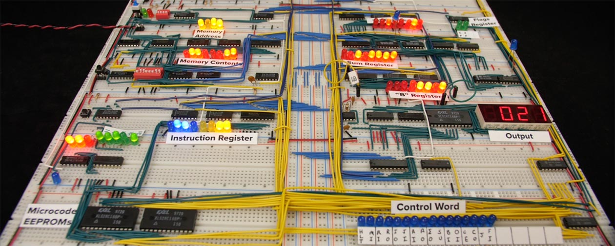
I create tutorial-style videos about electronics, computer architecture, networking, and various other technical subjects.
pine igloo
are there any easier projects
delicate quarry
There is a lot involved in low-level computing, but I find most people learn better with a practical example in front of them.
delicate quarry
Specifically for an 8-bit computer, not to my knowledge, but you an certainly start with Arduino-based kits instead, if that's your preference.
https://www.amazon.com/Arduino-Starter-Kit-English-Official/dp/B009UKZV0A is a pretty safe kit, though it in itself has no direct relation to the computing aspect of electronics.

This kit walks you through the basics of Arduino and electronics in a hands-on way. You will be able to build 15 projects using components that let you control the physical world through different kinds of sensors and actuators. Comes with a 170 page project guide book. Includes over 100 components
https://www.instructables.com/How-to-Build-an-8-Bit-Computer/ is a nice guide that walks through the elements of a breadboard computer. Probably not the best build guide, but it offers a lot of good information explaining the elements of such an assembly.
quiet osprey
Here ya go! All you could ever need. Only $12,213.90 https://www.digikey.com/en/products/detail/amd-xilinx/EK-U1-VCU128-G/10259825
😄
pine igloo
lmao
im reluctant to buy an arduino cus like
i wanna learn the BASICS basics
starting out with a microcontroller prolly wont teach me that
quiet osprey
True. A good text book like The Art of Electronics is the best intro to the basic basics that I know. Then again there's probably some great intros on YouTube.
delicate quarry
It really comes down to where you want to start and how deep you want to go. Technically, you can use C and code with direct register access instead of Arduino's C++ variant, but I did that as part of my Embedded Software course in college, so can't say I have guides to share for that.
Oh, @pine igloo https://www.falstad.com/circuit/e-index.html might be of interest to you. It's a free circuit simulator in your browser, so you can play with that alongside any other electronics resources you find. The examples included go pretty deep, too, from basic Ohm's law demonstrations to a recreation of the various parts of the original Pong circuit... I think there's an AVR simulator mixed in there somewhere, too.
quiet osprey
delicate quarry
> 1) A TPU split grommet that's a good snug fit around one of the various STEMMA...
Thanks for the input. Lots of good info. I might have to hit up the Tyco or Amphenol rep and see if I can get some samples of some super cool mil-spec bulkhead connector 😄
delicate quarry
quiet osprey
Thanks for the input. Lots of good info. I might have to hit up the Tyco or Amph...
I'm also a fan of these kinds of pluggable connectors, especially if you're not planning to make it necessarily weatherproof. https://www.digikey.com/en/products/detail/phoenix-contact/0707264/348293
Order today, ships today. 0707264 – 4 Position Terminal Block Header, Male Pins Green from Phoenix Contact. Pricing and Availability on millions of electronic components from Digi-Key Electronics.
quiet osprey
Cool. Phoenix Contact makes good stuff. Always been happy with their products.
delicate quarry
If all else fails, D-Sub connectors are pretty common and easy to install haha
More conductors then you need, but likely cheaper than the specialized connectors.
verbal aspen
There are also weatherproof RJ45 connectors and the like.
delicate quarry
Or panel-mount ethernet, if you plan to couple it with a nice I2C differential converter for extra range...
quiet osprey
Ha! Digikey - 4 position circular connectors. Only 31,000 to pick from
At that point I'll just stick a WiFi enabled feather or QTPie in the box with a LiPo!
Hey, here we go. Four contact, panel mout, Glenair 802 series. Rated for 1,000' immersion in salt water. Only $1,038.71 each. That's a deal!
icy moth
Lol
pine igloo
what is a 100-150$ max at least semi-automatic tool to use to make 3 holes of different diameter accross the thickness? what if they are square holes instead of circles?
'punch'
'square hole punch' reasonable search term
hearty karma
pine igloo
that are somewhat cheaper
You can go a couple of routes. One is electronics learning kits like Snap Circuits or the "100 in 1 electronics project" sets. They'll let you pick up the basics, but only go so far. The other route is to get a solderless breadboard, a handful of components, some jumpers, and optionally something like an Arduino if you want to do things with software. Then work through tutorials to build and understand how components and circuits work. Then you can build on that (with the same breadboard) to work with digital logic gates and work up to breadboard computers and the like.
 mental mica
well, this is annoying
the chip I need for a VFD project is only sold by 1 company because it's old-stock
which is fine, and they have an online order form
buuuuut their min. order quantity is 40 for a $6 chip
Currently wondering if I can call & get an exception, being a student
hearty karma
Allegro A6810?
 main hemlock
pine igloo
that are somewhat cheaper
main hemlock
pine igloo
that are somewhat cheaper
The Art of Electronics is good but extremely thorough. Some other books I found for a friend a while ago are: Make: Electronics by Charles Platt, and Electronics from the Ground Up by Ronald Quan
hearty karma
Also Getting Started in Electronics by Forrest M. Mims
mental mica
hearty karma
Allegro A6810?
MAX6850
main hemlock
I also like the textbook Electronic Principles by Malvino. The latest editions are pricey, like any textbook, but there are numerous older editions you should be able to find. I find the author does a good job explaining circuit design, not just analysis.
hearty karma
mental mica
MAX6850
It's worth asking them. There are other VFD driver chips offered by the aforementioned Allegro as well as Supertex
main hemlock
My benchmark was "does this book do a good job explaining how to design a simple class-A amp?". Very few actually did.
hearty karma
Ah, Supertex was acquired by Microchip
 humble thunder
okay, figured out something that was making me feel like i was going crazy while working on a project, but... turns out i wasn't as crazy as i thought, because it seems the 128x64 OLED FeatherWing's A and C buttons are actually wired backwards from what they should be, A is pin 9 and C is pin 5, instead of the other way around like the silkscreen on the board implies
mental mica
Currently contemplating a board design that'd have me soldering 8 TSSOP-28 packages by hand
quiet osprey
I worked for years with a lady that could do some insane hand soldering work. One time I screwed up a package foot print for a 200+ pin QFP and she managed to save my butt by bending the leads to where they would fit and soldered it by hand.
delicate quarry
You'd be surprised what's within the realm of doable with a soldering iron given the right supplies...
With a fine enough iron tip and proper pad placement, TSSOP shouldn't be very difficult at all for anyone who's done SMT rework before.
outer brook
Agreed, TSSOP ain't too bad
delicate quarry
Personally, I draw the line at QFN...
QFP isn't too bad, especially with flux and/or solder paste. Just carefully line up the pins on the edge and visually inspect for alignment before soldering the whole thing down.
I could probably manage QFN if I extended the pads enough, but it's not something I'd feel confident about.
violet torrent
mental mica
the chip I need for a VFD project is only sold by 1 company because it's old-sto...
VFD?
delicate quarry
violet torrent
VFD?
Vacuum-Flourescent Display. Basically the CRT-equivalent of character LCDs. You might see them on older microwaves or VCRs...
violet torrent
Oh, I was very unclear as to what I was asking! I was curious as to what VFD was being used cause I find them cool!
60's to 90's tech is what I have the most of as a collector
delicate quarry
Ah.
split willow
I have a matrix portal m4 with 32x32 panel and trying to build something that has 2 way communication with a PC via USB (no wifi available) My current thoughts are I can use the ESP and communicate with it via serial but I'm not a great C++ dev so it'll take a bit for me to build and serial communication might be hard 2-way. Other option is use circuitpython and communicate via text files on the USB drive mount. I'm a better python dev but there seems to be fewer libraries available (eg no python sand demo). Are there other options I'm missing or things I need to consider?
delicate quarry
split willow
I have a matrix portal m4 with 32x32 panel and trying to build something that ha...
How much data are you trying to send in each direction? Does it need to be full-duplex?
split willow
I think so. I'm not sure how I would sync the communication if I only have half duplex. My initial thought of writing/reading files on disk was the easiest way to transfer data I could think of
outer brook
RS-485?
delicate quarry
The M4 is single-threaded anyways for the most part, so I'm not sure what kind of sync you're looking for...
Send and receive are handled separately, and you could use asyncio to manage the sending and receiving of data asynchronously.
Is it alright if I ask what exactly you're trying to accomplish?
hearty karma
violet torrent
VFD?
AdaFruit used to sell some: https://www.adafruit.com/product/347

One up your plain old character LCD with a gorgeous VFD! These displays look and act just like character LCDs but are way glowier, and are very readable even from a distance. As a bonus, you ...
 jagged vapor
mental mica
the chip I need for a VFD project is only sold by 1 company because it's old-sto...
jagged vapor
mental mica
the chip I need for a VFD project is only sold by 1 company because it's old-sto...
I may have a couple of vfd drivers laying around if you'd like me to take a look
idk if they are the chip you're looking for, but thought I'd offer
split willow
delicate quarry
Is it alright if I ask what exactly you're trying to accomplish?
I want to create something like the sand/pixeldust demo but each grain is a process on a cluster of computers. As I tilt the board it would move the sand on the screen and also the processes will migrate on the computers. I can do the process migration parts, but I don't know how to visually represent that. The matrix is only ever plugged into 1 computer but it will communicate with the others to get data about what is running where
split willow
split willow
I want to create something like the sand/pixeldust demo but each grain is a proc...
I wanted some way to visualize how processes are spread across multiple machines and the light panel + sand demo was my first idea. I didn't realize the digital sand demo was all in C++. I looked at the raspberry pi hat too but it looks like the libraries have been deprecated so it seemed like it would be harder to get support for it
minor crag
so, I am going to remove a DIP-40 chip and replace it with a socket.. is there any reason I shouldn't consider using female machine pin headers over a standard chip socket for this task?
hearty karma
split willow
I wanted some way to visualize how processes are spread across multiple machines...
I remember seeing a tabletop model of a Connection Machine that had a visual effect like that recently.
hearty karma
minor crag
so, I am going to remove a DIP-40 chip and replace it with a socket.. is there a...
Machine pin headers have a pretty strong grip, so you'd need a lot of force to seat a chip that large, with the attendant risk of bending a pin.
hearty karma
split willow
I wanted some way to visualize how processes are spread across multiple machines...
Oh. Right. I know where I saw that. Right on the AdaFruit learn site: https://learn.adafruit.com/little-connection-machine
Adafruit Learning System
Build a Raspberry Pi case inspired by this iconic supercomputer
minor crag
alright
so machine pin headers are better as a semi-permanent solution, and not a good idea if you intend on doing a lot of removing and reinserting different chips or components into something
i thought about using one of those test sockets, with the lever, but they might be a bit too tall
karmic obsidian
WE ARE LIVE! ASK AN ENGINEER! https://youtu.be/_hk6d_s7VW8

ASK AN ENGINEER 5/4/2022 LIVE!
Visit the Adafruit shop online - http://www.adafruit.com
LIVE CHAT IS HERE! http://adafru.it/discord
Adafruit on Instagram: https://www.instagram.com/adafruit
Subscribe to Adafruit on YouTube: http://adafru.it/subscribe
New tutorials on the Adafruit Learning System: ht...
 safe edge
Is there an Elon rocket model?
pine igloo
hey among all adafruit product anything that can fit a 1 inch diameter circle (ex-compass plastic box) powered by coin/button battery with at least 4-5 gpios ?
am I correct to think only itsybitsy and trinkets would potentially work ?
pine igloo
worried about heat because this would be on a keyholder in my pocket
violet torrent
The QT Py line fits the same form factor and GPIO profile as the Seeed Xiao, it's very small
delicate quarry
QTPY might just barely be outside that 1" diameter, due to its diagonals.
It certainly fits a 1" square, but a circle is tight.
It's probably worth noting a coin cell battery's nominal voltage is 3.0V, so it might be a bit low for most microcontrollers.
violet torrent
lemme check with mine
pine igloo
it's slightly more than 1 inch, according to measure tape, seems like 1.1/1.15/1.2
violet torrent
I have a set of vernier calipers so I can check diagonal
pine igloo
it's a compass box so less than 4-5mm thick
pine igloo
but I'm open to buying another one of these keyholder and putting another compass box under it to have 9-10mm
outer brook
Ah, wrong parameter
violet torrent
mine is in cm/mm, and it's 2.54cm
outer brook
Yeah, .99261
pine igloo
what about heat, am I going to see vent hole or I can sort of seal it ?
outer brook
If it's up against the metal (not great idea), you wouldn't need to worry about it. If you can find something that is electrically insulating but heat conducting to line it with, that would be ideal
pine igloo
nah it's a compass box so soft plastic backing
but I guess I could tape some aluminum foil back there throught an hole
violet torrent
Not sure you really need to worry about the heat generation from a microcontroller chip
pine igloo
or aluminium foil with thing cut lines in it to make it breath
was only worried because it would mostly be in my pocket in an almost sealed plastic box all day long
outer brook
AL foil against the MCU board is not the best idea
AL conducts electricity
So
Shorts!
pine igloo
ah I thought it would like an heatsink but yeah...
I guess the coin holder/button holder for the battery is an aftermarket part since it only seems to support usb power ?
outer brook
You can hack in external power
pine igloo
I guess this qualify as a wearable I guess....
violet torrent
I sincerely doubt you'll need a heatsink, just looking at an RP2040 (the QT Py variant I possess) it doesn't seem to get too hot, and it's temp ratings are much higher and lower than a human body could make it
You'll feel it before it'll break
outer brook
A heatsink wouldn't work well either
Heat sinks are meant to help get the heat elsewhere, they generally require a fluid
pine igloo
I just meant as in there is no ventilation, nothing to remove the heat
violet torrent
that's fair
outer brook
I agree with Z, they are likely correct that it's not a big deal
pine igloo
so it's going to marinate in its heat all day
violet torrent
it's basically going to probably be inconsequential
pine igloo
Just need to figure out a better solution than carrying a 4xAA battery holder now (which would probably produce uncomfortable heat)
violet torrent
Lots of people make wearable projects with microcontrollers and I haven't heard of anyone needing heat dissipation
I use 3xAAs to power my portable project and that's never produced too much heat
Adafruit produce a JST AA holder
delicate quarry
pine igloo
Just need to figure out a better solution than carrying a 4xAA battery holder no...
If your wearable is generating heat, your load is drawing enough power to generate heat. Changing the battery won't help with that.
(it is more portable, though.)
pine igloo
they all says 3.3V regulator, so I suppose I can put 3x1.2V in there or 4x1.2V or 4x1.5V and it level it down to 3.3 ?
violet torrent
I should find my 8xAA holder somewhere
pine igloo
I think there is a qt samd51 one, a rp2040 one and an ESC one not sure yet which one I'll pick exactly
delicate quarry
3x coin cell should work, if you design a holder for it.
pine igloo
I have a spare holder for 4xAA, problem with coin cell is they barely have any energy
delicate quarry
Don't use ESP32 unless you need the wireless capabilities. They tend to draw more current than the alternatives.
pine igloo
and I have 40 spare NiCd
that can still recharge 100 times or so
"Waterproof 3xAA Battery Holder with On/Off Switch" sounds less bulky and more safe if it rain/snow though
violet torrent
There should be a voltage regulator on board, and they should tolerate 4.5V on the 5V input (with a shottky diode to prevent backpowering when you plug in the USB port)
pine igloo
ok last question because I don't completely understand stemma
Space for 1 stemma connection, so 1 stemma sensor the rest I have to solder ?
 violet torrent
stemma sensors are able to be chained, it's why there's 2 ports on most sensors, cause each sensor is addressable on a shared data bus (I2C)
pine igloo
stemma provide ground/vcc and gpio to each other then ?!
violet torrent
VCC and GND are also shared yes
violet torrent
the gpio that is shared is just the i2c bus
pine igloo
finally a project that won't cost tons of money 🙂
also got new colored tapes for my polulu zumo robot so I can make more tracks/more stops etc
I only had yellow and black and now I have blue, red and green 🙂
 mild thistle
What’s the difference between vcc and vdd?
violet torrent
So the double letter sometimes refers to the transistor use, such as BJT having VCC and VEE for Collector and Emitter; with FET having VDD and VSS as Drain and Source
VEE and VSS aren't necessarily GND, more just the negative supply voltage, but a lot of the time people tie that to ground instead of having it floating
violet torrent
Nowadays it's all a bit more complicated
mild thistle
violet torrent
VEE and VSS aren't necessarily GND, more just the negative supply voltage, but a...
If you used a p channel wouldn’t that be positive voltage tho?
violet torrent
Especially because of CMOS logic
mild thistle
Or maybe n channel I always get polarity wrong
violet torrent
mild thistle
If you used a p channel wouldn’t that be positive voltage tho?
idk this is just the convention
It really depends on who is labelling it
mild thistle
Lol
hearty karma
I'll often refer to "the zero volt reference" instead of "ground", to make it clearer what I'm referring to.
violet torrent
I just had a read of the wikipedia page tbh
(it was an interesting question I didn't know the answer to, so i was happy to look it up)
mild thistle
I am going to make the april fools fluke keyboard in real life
 halcyon hazel
I found a vintage Tektronix oscilloscope for $50. As a beginner, is this worth getting? I've been borrowing a scope for some audio stuff I've been working on and I've found it useful, so I'd like to have my own.
delicate quarry
If you're dealing with audio and have space/budget for it, probably? What model?
halcyon hazel
Tektronix 453
Yeah it's pretty big and heavy, and possibly noisy too. But I think I can manage that. Just seems like a good deal compared to spending $300 or more on a modern scope.
Maybe if I get more into this stuff later I'll make that investment into a more modern scope.
 vagrant gyro
were you borrowing a more modern scope? was it a digital storage scope? you mention "audio", so may be useful for that application, but those older, non-storage scopes can be pretty limiting
halcyon hazel
Yeah it's a digital scope. I don't know if it has storage but I assume it does.
vagrant gyro
for $50 - could just setup it up to display lissajous and let it be throwback art
halcyon hazel
I've just been using it to see the output audio waveform. I think even the old scopes can handle that just fine right?
vagrant gyro
yep. i'd think so. that's something that generally doesn't need storage. you're just constantly looking at the latest trace.
halcyon hazel
Alright, thank you
humble thunder
old analog scopes can also be used to watch some awesome oscilloscope art! lol
 tulip bloom
Where can i get help with billing issues?
I tried emailing support but they stopped replying to me and didnt help
My address was flagged for fraud apparently and they wont ship to me
This is my first time buying from adafruit btw
 solemn field
tulip bloom
Where can i get help with billing issues?
solemn field
tulip bloom
Where can i get help with billing issues?
Give me a moment to look into it.
tulip bloom
solemn field
Give me a moment to look into it.
Thank you !
karmic obsidian
hi scatman (pt from adafruit here)
@tulip bloom i can take a look, can you provide part of the email message so i can look it up?
time/date and/or something not personal i can search with
karmic obsidian
@tulip bloom if there was a previous order shipped to a location that was a chargeback or an issue, the address may not be ship-able to again
there are a lot of locations during the "pi shortage" we are not shipping to, since this is related to raspberry pi orders, that is probably why
so! @tulip bloom please try another vendor for raspberry pi units, there is a shortage and we're dealing with a lot of constraints and automated order attempts and everything
tulip bloom
But ive never ordered from you guys before my account literally has 0 order history. Is it possible to get the flag removed?
karmic obsidian
@tulip bloom since this is for a raspberry pi order, not at this time - we're dealing with a lot of automated attempts so for now, please try another vendor for raspberry pi units
tulip bloom
karmic obsidian
<@276461284298326018> since this is for a raspberry pi order, not at this time -...
Can i try shipping to a different address with my account or is my whole account screwed for buying pi’s?
karmic obsidian
to be straight up, buying pi's is going to be tough
you are welcome to try another address, however - for the most part getting pi units is going to be tough since we're dealing with a lot of attempts for a small number of units - we're working on this to make things easier/better, but it's really challenging right now
tulip bloom
I had an order already and had even already been charged for it but because of the account flag it didnt let me complete the order
karmic obsidian
@tulip bloom you will not be charged for any order
tulip bloom
Yea i know it was temporary thats gone already i just included that part to show how close i was
karmic obsidian
yep, it's a giant challenge right now with thousands of people trying to get hundreds of pi units, right now there is a lot of this - you are welcome to try again to another location, however - it's going to be tough getting any pi units for a very long time
tulip bloom
Is there any way to check if the other address is flagged too? Or i just have to try again and find out
karmic obsidian
@tulip bloom correct - on checkout is how you'll know - i do not want to take up more space here in the general channel, but thanks for reaching out and i'm sorry about the pi situation, it's going to be like this for awhile 😦
tulip bloom
Ok thanks!
 cold pebble
A number of items (all out of stock for some time) in my Wishlist have been marked "Maximum 1 per order" (never used to be marked that way). I have 2FA enabled.
Is that related to the Raspberry Pi protections, or just general supply chain / fairness? (only one item has relevance to Raspberry Pi)
main hemlock
cold pebble
A number of items (all out of stock for some time) in my Wishlist have been mark...
like for example?
cold pebble
Pixie Chroma (5409)
main hemlock
that's out of stock at the moment, is there another thing that's in stock?
cold pebble
floppy cable 5453, the rest are out of stock for quite some time or I'd have ordered them by now 😉
it's mostly out of stock items that newly have the 1 per order notice
main hemlock
I added that to an empty wishlist and don't see the max 1 notice. Could you send a screentshot?

I"m just trying to figure out if there's a bug and the "max 1" for some RPi thing is infecting the other listings
cold pebble
I tried deleting it and re-adding it andstill get the notice
 main hemlock
does everything in the wishlist have max 1?
cold pebble
the only thing that doesn't is pushbuttons 5236
main hemlock
if you remove the rpi thing and refresh, does it change?
cold pebble
yes!
main hemlock
what was the RPi item?
cold pebble
Zero 2 W
if I re-add the Zero 2 W, the list is good again/still (except of course the Zero 2 W has the limit)
so I'm good, thanks, sounds like maybe retrofitting the limit was the infectious aspect
main hemlock
I think that out of stock things get that notice when there is a max 1 item that is oos. That seems like a bug. I'll report it
main hemlock
web folks say thanks and fix is in the works
 pearl heart
Are there any smaller tft displays capable of running at 60fps? I have a 160x128 st7735 based display but I wasn't aware of how limited they are in terms of speed
humble thunder
i don't think Adafruit makes breakouts for the very tiny displays that aren't just SPI or I2C
which is likely where the slowness is coming from, that is... the interface to the display
humble thunder
for example: https://www.adafruit.com/product/2050 all the pins on the other side of that breakout

Add some jazz & pizazz to your project with a color touchscreen LCD. This TFT display is big (3.5" diagonal) bright (6 white-LED backlight) and colorful! 480x320 pixels with ...
delicate quarry
pearl heart
Are there any smaller tft displays capable of running at 60fps? I have a 160x128...
You could look for a small 8-bit parallel display if you need 60fps, but the smallest size I know for those is around 2.4"?
pearl heart
That's probably small enough
humble thunder
which is actually the exact product i think @lost lily was talking about too lol, the other side there is a high-speed 8-bit parallel connector, downside is that it requires a crapton of pins to drive, but it lets you drive the display far faster
oh, i linked the 3.5" one, there's a 2.8" one too
 lost lily
(here's the 2.8 one: https://www.adafruit.com/product/2090)
pearl heart
12-13 pins is kind of a lot hahaha but a fair trade off
delicate quarry
40MHz SPI is not easy to achieve with most microcontrollers, even an ESP32 has heavy restrictions past 20MHz...
60fps displays on PCs are typically handled by dedicated graphics hardware peripherals, it's pretty hard for a microcontroller to replicate that.
lost lily
delicate quarry
40MHz SPI is not easy to achieve with most microcontrollers, even an ESP32 has h...
I've set my SPI speed for my ESP32 clone to the display I mentioned above and the display works fine
(just saying)
You obviously need to use the hardware SPI peripheral
And short connections
delicate quarry
Actually, 160x128 is pretty small, 60 fps should be achievable with even 10MHz SPI...? What is the default bus speed?
minor crag
hmm, I am looking at some of the new ARM based chips coming out this year, or have recently come out, and these things are getting pretty dang close to the performance of a full size PC
pine igloo
grand central gone from mouser/digikey canada 😢
pine igloo
big enough to fit a touch screen, a pi, lipo, holes for standard connectors etc
and grill for air circulation and for speakers
pine igloo
cheapest dvd player shaped object money can buy (got it for the enclosure)

also removable power cord as expected/wanted
hearty karma
That's a nice little heatsink too
pine igloo
yeah and a big massive 400V capacitor in there
trying to ID it, it has three PCBs, one for mains, one for logic and one for front "basic/primitive display that only show time"
hearty karma
That's probably part of the power supply, those are nice capacitors
pine igloo
mains pcb

saw one in the trash and liked what I saw inside (the dvd reader is enclosed too so nice place to put a lipo or other staff
and I don't know about used parts in dvd, so prefered to get something new that had never been powered on so the cap doesn't discharge on me or the laser...
costed me 18$, play 1080p dvd technically so very obsolete, but it's a very bad brand (ie: in-house for flea market) so the plastic gear in the dvd wear out after a few weeks, no anti-vibration for the tray etc
10uF capacitor, max voltage is 450V. Aishi CD11GH series
transformer is kinda cute (tape to hold the copper coils :rofl:)

their is a 0.1uF safety capacitor (never heard of those before)
DIP-8 Relay on it: "device is offered in 36.9 mA Coil Current, the device has a 24 VDC of Coil Voltage, and Switching Voltage is 250 VAC 125 VDC, and the Coil Resistance is 650 Ohms, and Contact Current Rating is 10 A, and the Power Consumption is 900 mW.". I guess this is what give power to the second PCB not connected to power at 24VDC ?
hearty karma
There are a few kind of safety capacitors made, with different ratings for across-the-line (X class) and line-to-ground (Y class).
pine igloo
what I find weird is all these components ID printed on the board along with non-conductive white lines
hearty karma
The relay is controlled by 24V, but may switch some other voltage
pine igloo
I bet if I desoldered everything it would looks like a schematic
hearty karma
I do appreciate well done silkscreening
pine igloo
seem to be the cheapest of the cheapest components for a spec, most of them for for 2-3$ for a pack of 10 on ebay
but all seem salvageable, the DIP8 has a clearance of 1.5mm under it, enough to cut out the connection to the PCB and still have a usable chip if I really wanted to
hearty karma
There are various ways to unsolder DIPs intact
pine igloo
SMT Crystal Oscillator - 27.000 MHz on the non-mains PCB, motor driver ic chip (can't find a datasheet), cefeon flash chip (will need magnygying glass to see the model on any of these
they all seem smd with a lot of pins so unsalvagable
enclosure almost 100% excavated

dvd back and hopefully nice motors and laser

because of the pic above I know I can use hot glue in there 🙂
what is your take on the motor ? are they potentially reusable ?
Only 2 wires, seems easy to salvage
hearty karma
pine igloo
what is your take on the motor ? are they potentially reusable ?
The motor is likely similar to this: https://www.adafruit.com/product/3882
What's this? A record player for ants?? Not at all! This is a DVD/CD Spindle Motor, that thing that's inside a CD or DVD player, that turns the disc around really fast. These motors ...
 desert cipher
hah gonna love ksp reference
pine igloo
bah the heatsink is stuck to the chip over some kind of white paste
can't see the chip underneath, would have loved to know the used microcontroller. Also 64mb of flash memory on board which seem to costs 3-4$ which is good to know
hearty karma
Probably thermal paste. The chip is likely a product-specific one, not a generic microcontroller.
pine igloo
yeah seems it's a systems on board for dvd player/games on dvd
hearty karma
I took apart a karaoke player once and (aside from the video monitor) it was basically one huge integrated circuit inside.
pine igloo
yep the flash memory was in a socket though but I was able to remove it (DIP) but with a scratch and bent leg
hearty karma
I found a kid's toy with an SD card in it, but the card was glued in 😦
pine igloo
which shouldn't matter much but the brand isn't really sold on mainstream electronics resellers
so without the datasheet it's useless
hearty karma
I haven't seen DIP format flash in a while, other than serial flash.
If it's DIP-8, there are only a few common versions.
pine igloo
maybe you have better ones than me
 hearty karma
Ah, it is DIP-8. Most of those use the same Winbond pinout.
 pine igloo
I expect it will have some sort of sector to prevent reading thought since these are highly-protected dvd reading devices
hearty karma
Honestly I'd be surprised if they even bothered, not that it matters, you'd probably just want to rewrite the chip with your own data anyway.
pine igloo
and they normally secure the chips so that someone can't make illegal/unregulated readers of DVD