#general-tech
1 messages · Page 145 of 1
 lethal valve
But for hobby use you wouldn't need to worry about those?
 harsh void
Basically you can perform an "LED" test where you limit current to 10mA and voltage to maximum
Connect led when it's off and switch it on
If the LED is alive and it shows 10mA and correct voltage drop on LED - it's ok
If LED dies - it's trash
You can learn more by searching about power supplies on yt
Usually low cost Chinese ones like this are pretty bad
Especially when they are as this - switching mode power supplies
lethal valve
Im pretty sure it's linear
harsh void

Then why they add some crappy images
Linear power supply has usually big transformer inside
And they are quite heavy
 steady kite
I remember when i told my dad about switching power supplies the 1st time
he could not comprehend the idea.
harsh void
I mean they are cool
But only when made well
Microprocessor based ones are quite ok
But still depends
steady kite
he was under the impression you always need a transformer
lethal valve
imagining a microwave transformer in one of these
steady kite
that's over kill madness
harsh void
steady kite
he was under the impression you always need a transformer
I mean there is always a transformer, just working in other way 😳
lethal valve
200kv output
harsh void
Anyway - for me it looks a bit sketchy
harsh void
You can buy it and I'm sure it will have spikes when switching
lethal valve
It's alright just for basic stuffz
steady kite
@harsh void he thought you would need a massive transformer to just switch between 220 and 110
lethal valve
me?
steady kite
my dad
lethal valve
oh lol

 lethal valve
Ok thanksz
lethal valve
I actually have one of these units at my workplace
we use them to charge batteries
for like 5 yrs
lethal valve
the ripple is low
lol
i think we also have a ups system made out of super capacitors
harsh void
What
lethal valve
what
harsh void
That would be massive and expensive
harsh void
Maybe makes sense
 violet torrent
Morning everyone
lethal valve
good afternoon
lethal valve
does anyone know where i can buy a raspberry pi zero 2 lol everywhere is out of stock!
harsh void
Because of production problems
Lol
We actually have plenty of them in my country
Like 400 on one shop
Interesting
lethal valve
I guess your european?
harsh void
Yeah
lethal valve
What shop? cool
harsh void
Botland
It's not that cheap shop tho
We also have 2 popular sites where everyone can sell stuff and there is a lot of interesting things
lethal valve
i know but atleast it's in stock!
harsh void
Some time ago I bought 10x ATtiny10
Now I can't find them anywhere
Only in China for like 10x the price
Or more
Pretty bad times for electronics
Everything is in small amounts and pretty expensive
 spark cliff
lethal valve
does anyone know where i can buy a raspberry pi zero 2 lol everywhere is out of ...
spark cliff
lethal valve
does anyone know where i can buy a raspberry pi zero 2 lol everywhere is out of ...
Have you tried https://www.sfettechnolgies.co.uk/ just got mine last week. A bit expensive but it was fast and the only one available in the UK lol.
lethal valve
spark cliff
Have you tried https://www.sfettechnolgies.co.uk/ just got mine last week. A bit...
thanks!!!!!!!
harsh void
I was surprised when I ordered from china and it was like 3 weeks and quite cheap
Free delivery
But usually it's not worth
 uncut summit
So with Visual Studio Code and both PlatformIO and ESP-IDF I can now program all the ESP8266/ESP32/ESP32-S2/ESP32-S3 boards including the latest from Espressif S3 boards that are on Adafruit site. Learning the ESP-IDF framework was a bit of a challenge.
 normal helm
I need help
 cold pebble
@Exbountyhunter#5467 Best to ask your specific question, different people have different knowledge (please don't cross-post in multiple channels)
uncut summit
tip: if you have a qt-py and a seeduino expansion put a piece of tape on the bottom of the qt-py to cover the 5v/GND/c-r-d pads because if you plug into the expansion the 5v will connect to the seeduino debug pin and cause power drop resulting in board put into safe mode.
 ornate egret
hi
uncut summit
yo
 swift pendant
anyone here can link me to some online video or documentation that simplifies how ram, address memory and registers work?
swift pendant
uncut summit
yo
can you help me out?
uncut summit
what sort of help you looking for
 hearty karma
swift pendant
anyone here can link me to some online video or documentation that simplifies ho...
hearty karma
swift pendant
anyone here can link me to some online video or documentation that simplifies ho...
One possibility is Ben Eater's videos on youtube, where he builds simple computers on breadboards from the ground up.
uncut summit
yes those are really good
swift pendant
hearty karma
One possibility is Ben Eater's videos on youtube, where he builds simple compute...
was actually checking those out, i came across something called instruction cycles
and i read that the time it takes for a cycle has increased over the years, but i dont understand what this really means
hearty karma
Earlier CPUs tended to take several clocks to process an instruction, but more recent ("RISC") CPUs can process an instruction per clock. However, many of them use a "pipelined" execution model, where the various phases of processing are all happening at once, so the CPU will be finishing one instruction at the same time it's starting another, or in some cases, several will be in-process at once.
uncut summit
There are two types of CPU's CISC and RISC, CISC stands for complex instruction set, and RISC stands for reduced instruction set. In a intel CPU for example it has a series of instructions it can perform such as move or copy or load, there are more than 100 of these instructions and these instructions can take different amount of clock cycles to complete. In a RISC they simplify the instructions so that they take same amount of clock cycles to do each instruction but it takes more of them to complete the same job. In modern CPU's there is pipelining and other features to optimize the flow of instructions that the CPU will perform. When learning this it's best to look at old simple CPU's like a 6502 or a Z80. A 6502 has only 56 instructions and is easy to learn.
 verbal aspen
Just to be pedantic, RISC instructions can take different numbers of clock cycles too.
uncut summit
no fixed
@hearty karma is right usually one instruction per clock
Back in the 80's when Intel came out with the 8088 4.7 Mhz cpu another company came out with the NEC V20 clone but NEC optimized their cpu to shave off clock cycles for the instructions thus their cpu behaved like it was abount 20% faster
1981 4.7Mhz 2022 5Ghz
how far we have come
original 6502 1 Mhz
6502 could address 64K ram only
 gloomy mango
I really should buy parts for my 8086...
Saying that, I should build my Z80s first.
hearty karma
I'm breadboarding an 1802, and vaguely considering trying to breadboard an 8008 (a CPU in an 18-pin DIP is amusing, the odd MC14500 1-bit CPU fits in a 16-pin DIP).
 static yarrow
does anyone know any good starting point for esp8266 with arduino ide ??
I am interested in the WiFi stuff the board offers (I am pretty familiar with the non wifi stuff)
I want to know if there is a youtube playlist or a pdf or website that teaches you esp8266 wifi ??
I am currently reading the docs of ESP8266WiFi.h library which do give some overview of concept
but are there some other resources that i could use ??
 cloud walrus
static yarrow
does anyone know any good starting point for esp8266 with arduino ide ??
I am ...
cloud walrus
static yarrow
does anyone know any good starting point for esp8266 with arduino ide ??
I am ...
Have you looked at this example?https://learn.adafruit.com/adafruit-feather-huzzah-esp8266/using-arduino-ide

Adafruit Learning System
WiFi with built-in battery charging for IoT on-the-go!
static yarrow
cloud walrus
Have you looked at this example?https://learn.adafruit.com/adafruit-feather-huzz...
I have not , but i will 👍
If you have anything more , just ping me
cloud walrus
I don't know which esp8266 board you have but the wifi example should work on any https://learn.adafruit.com/adafruit-feather-huzzah-esp8266/using-arduino-ide#connecting-via-wifi-2720763-33
There are more examples here: https://learn.adafruit.com/home-automation-in-the-cloud-with-the-esp8266-and-adafruit-io
static yarrow
cloud walrus
I don't know which esp8266 board you have but the wifi example should work on an...
I have this board but with the other usb chip(cp2102 iirc)
I know the basics to work with the board like how to use i2c , spi on the board , how to flash to board etc
but as i said, i dont know much about wifi part of esp8266, like which libraries are there ? how to make https requests ? how to set up a web server that serves static html ? etc etc
 static yarrow
cloud walrus
There are more examples here: <https://learn.adafruit.com/home-automation-in-the...
static yarrow
cloud walrus
There are more examples here: <https://learn.adafruit.com/home-automation-in-the...
Thanks 👍
cloud walrus
You're welcome -- Have fun!
 pine igloo
What's the name of the component that requires a minimum voltage for it to allow current to flow?
violet torrent
transistor?
Also, I love how just a week or so ago a video was posted using the Pico to drive a floppy disc, and I just got my hands on an IDE floppy drive and was thinking of doing the same thing
pine igloo
violet torrent
transistor?
Yes, but which one exactly? I need one that doesn't just amplify, say, 0.1-0.6v. It needs to amplify none of it or all of it.
 delicate quarry
pine igloo
Yes, but which one exactly? I need one that doesn't just amplify, say, 0.1-0.6v....
delicate quarry
pine igloo
Yes, but which one exactly? I need one that doesn't just amplify, say, 0.1-0.6v....
I don’t think there’s such a concept for a transistor. While there is a minimum voltage for transistors, applying higher voltages to the gate (within reason) is usually not an issue for the rest of the transistor’s function.
There are many types of transistors, sure, but they have less to do with amplification and more to do with configuration.
Unless there’s more context to this I’m not aware of?
hearty karma
You could be describing a transistor in some sense, they don't really start to conduct until you reach the threshold voltage (FETs) or forward drop (BJTs). But if you want to switch from "fully off" to "fully on" at a specific voltage, you might look at a component known as a "comparator".
pine igloo
delicate quarry
Unless there’s more context to this I’m not aware of?
I'm trying to make a solar powered lamp, but I don't want a really small flown of current going into the capacitor, because that prevents the capacitor from actually discharging.
pine igloo
hearty karma
You could be describing a transistor in some sense, they don't really start to c...
Thanks, I'll look into it.
delicate quarry
pine igloo
I'm trying to make a solar powered lamp, but I don't want a really small flown o...
Another option would be a logic buffer, if you just need a distinct gap between logic high and logic low.
hearty karma
Solar lamps typically contain a little integrated circuit (such as YX8018) that manages charging/discharging. Doing it yourself trying to avoid charging/discharging at the wrong time can be tricky, as you're working with low voltages and low currents, and there are lots of stray effects to avoid.
pine igloo
Alright, thanks guys.
 civic pewter
Hey guys! My son wants to get a Circuit Playground (8yr old, loves scratch and code.org) and I was wondering should I get him the Playground Express or the Bluetooth (since BTLE isnt compatible w/ MakeCode) ?
cloud walrus
civic pewter
Hey guys! My son wants to get a Circuit Playground (8yr old, loves scratch and c...
If I am not mistaken, you can use the CircuitPlayground Bluefruit with MakeCode. If that is the case, I'd go for the Bluefruit because there is so much more you can do with the nrf52840 than with the samd21 in the Express.
hearty karma
You can also use the CPX with Scratch. https://blog.adafruit.com/2020/01/14/a-scratch-3-extension-for-the-circuit-playground-express-circuitplaygroundexpress-scratch-programming/

Adafruit Industries - Makers, hackers, artists, designers and engineers!
Alan Yorinks posts on Twitter availability of a Scratch 3 language extension for the Adafruit Circuit Playground Express microcontroller board. I’ve just released a #Scratch3 extension for th…
cloud walrus
I expect the CPX will be fine for a long time at that age. I was thinking more if Dad wanted to play with it as well 😉
I would recommend the CircutPlayground Express over the CIrcuitPlayground "Classic"
 minor crag
hey everyone
minor crag
I am looking at some micro controllers trying to find one to work for general purpose projects
cold pebble
Arduino? CircuitPython? Do you need wifi? BLE? lots of flash for images or audio? lots of RAM for large programs or large data? Lots of pins?
minor crag
the flexibility to use arduino or circuitpython or micropython is good.. and while I can't envision a project requiring wifi, I may find it useful later.. lots of pins is good
eventually, I'd like to make a chip flasher out of one, but that's a specific use case requiring the number of pins the arduino mega offers, and I can buy a board specific for that.. so a decent amount of pins is good, but something like a Seeeduino Xiao has too few
I basically see RP2040, ATSAMD21, ATSAMD51, and ESP32-S2 stuff being the most common
cold pebble
Arduino/Metro form factor gives lots of pins, available with various processors. Feather form factor has many processor choices, and a lot of stackable peripheral boards. Itsy Butsy and QT Py form factors are great for small stuff.
minor crag
whats the advantage of the feather form factor besides being able to fit it in more stuff?
cold pebble
Those are all good options, although I'd shy away from SAMD21 unless you know your applicatiosn will be limited and will fit in RAM (less of an issue with Arduino IDE)
minor crag
yeah, I had to use a Seeeduino Xiao for something recently, and found a lot of scripts had a hard time compiling for it, it's SAMD21
so something that's going to be fairly compatible with scripts and examples I can find and build from
cold pebble
Feather mainly allows easy stacking, many choices https://www.adafruit.com/category/943
minor crag
you say SAMD21 has issues with that.. so bump that off the list.. RP2040, ESP32-S2, and SAMD51
what I can stack on a feather doesn't seem relevant, since I am looking for something to use just for testing and experimenting
cold pebble
SAMD51 is very mature and popular. ESP32-S2 has wifi and a lot of RAM. RP2040 is a good processor, very available.
minor crag
is there an advantage to the Metro form factor?.. more pins maybe? other features/
cold pebble
not sure about Arduino support for RP2040
 haughty flare
minor crag
whats the advantage of the feather form factor besides being able to fit it in m...
haughty flare
minor crag
whats the advantage of the feather form factor besides being able to fit it in m...
my opinion: its small size but high number of gpio pins, built in leds, and stemma connector coupled with a built in charger make this an ideal choice for many projects where space is a premium but functions are many. couple it with a 5v booster and you have a decent platform for just about any project. i suggest the rp2040 as you can program stuff on it and transfer the code to another device with minor tweeks
cold pebble
Metro has more pins and there are shields to match, and depending on the board maybe additional features there isn't room for on smaller processors
minor crag
space won't be an issue, since I'm looking for something to test code out on that will likely be ported to other, smaller, more purpose built devices or maybe even at some point to individual ICs
preferably not micro USB though.. I mean, it is 2022 already right?
cold pebble
there's an adapter for that 😉
minor crag
it seems RP2040 or ESP32-S2 is the way to go
i should mention it's going to be so testing centric that I may even put screw terminals on it
something to go to when I have those "I wonder if I can do that with an arduino" moments
 steady gulch
like that ? https://www.adafruit.com/product/2926

The Terminal Block Breakout FeatherWing kit is like the Golden Eagle of prototyping FeatherWings (eg. majestic, powerful, good-looking). To start, you get a nice prototyping area ...
haughty flare
minor crag
is there an advantage to the Metro form factor?.. more pins maybe? other featur...
the metro is nice. while i havent programmed or anything on it yet, the number of pins is higher than the feather but the board is 3 times as big for 2 extra analog pins and a few extra features. but if space isnt an issue, the metro m4 is a good choice and it features 5v support but lacks charging capabilities and a stemma port, bu a proto and a powerboost shield solve that issue
minor crag
yeah.. I'd prefer a board with no headers soldered on so I can add those to it straight up, no feather necessary
steady gulch
there's a featherwing for everything 😉 (ok probably not, but there's a few)
cold pebble
there's a Metro terminal block shield too
minor crag
no RP2040 on a metro sized device?
cold pebble
yeah, battery is a useful consideration
haughty flare
i do believe there is a board with screw terminalt for the metro and one for the feather
cold pebble
not yet, "coming soon" I think (RP2040 Metro) ...or at least in some stage of prototype, no guarantee of product)
minor crag
hmm
haughty flare
minor crag
no RP2040 on a metro sized device?
the metro m4 does support circuit python though, which is why i got it
minor crag
wifi excluded, is there any notable benefits to either the RP2040 or ESP32-S2 over the other?
or for that matter the SAMD51
cold pebble
most ESP32-S2 boards have 2MB RAM
haughty flare
for me its the code. so far i know html, gcode, and circuit python coding, only one f which is any use here
cold pebble
RP2040 has 264k RAM, SAMD51 has either 192k or 256k depending on board
cloud walrus
If you want something without headers you may be limited to the feathers -- or the Grand Central https://www.adafruit.com/product/4084 but it's out of stock.
cold pebble
QT Py and Itsy Bitsy will also be w/o headrs
minor crag
well, I have a desoldering gun so... there's that option
cold pebble
Does MicroPython support any other boards than http://docs.micropython.org/en/latest/
minor crag
also, what's the ESP32-S3 stuff I see listed?
haughty flare
minor crag
well, I have a desoldering gun so... there's that option
https://www.adafruit.com/category/17 this givs you a proto board and screw terminals all without having to remove the headers from a feather, which will allow you to have what you want and keep stackability
Adafruit Industries, Unique & fun DIY electronics and kits : Arduino - Tools Gift Certificates Arduino Cables Sensors LEDs Books Breakout Boards Power EL Wire/Tape/Panel Components & Parts LCDs & Displays Wearables Prototyping Raspberry Pi Wireless Young Engineers 3D printing NeoPixels Kits & Projects Robotics & CNC Accessories Cosplay/Costuming...
cold pebble
Adafruit learn guide pages for RP2040 say "At the time of launch, there is no Arduino core support for this board. There is great C/C++ support, an official MicroPython port, and a CircuitPython port!" ...not sure if that's current info.
cloud walrus
more here https://micropython.org/download/
cold pebble
@minor cragESP32-S3 is basically alpha at this point, and hard to come by other than manufacturer dev boards
haughty flare
minor crag
well, I have a desoldering gun so... there's that option
https://www.adafruit.com/product/196 and this does the same thing for arduino shaped board

The next generation Proto-ScrewShield is a dual-purpose prototyping shield. Not only does it have a large 0.1" grid prototyping area but it also extends the Arduino pins to sturdy, ...
cloud walrus
minor crag
wifi excluded, is there any notable benefits to either the RP2040 or ESP32-S2 ov...
get one of each...
cold pebble
and a SAMD51 to round things out 🙂
cloud walrus
yes! Always nice to have options.
minor crag
so will the ESP32-S3 surpass the others at some point?
cold pebble
each of these processors has its pros and cons, all depends on the intended applications
minor crag
hmm.. I actually have an RP2040 I bought recently.. forgot I had it
cloud walrus
The S2 does not have BLE. That is a nice addition in the S3
haughty flare
https://www.adafruit.com/product/2926 sorry, linked the wrong thing for the feather screw termias
The Terminal Block Breakout FeatherWing kit is like the Golden Eagle of prototyping FeatherWings (eg. majestic, powerful, good-looking). To start, you get a nice prototyping area ...
minor crag
I do plan on designing some peripherals and mods for older video game consoles
bluetooth may become useful to have at some point
maybe 2.4ghz as well, but I doubt the wifi chip could be configured to do that
haughty flare
i have a bluetooth shield for the metro. havent used it yet, but its nice that it comes with a built in proto
cloud walrus
but as noted S3 support is new and evolving fast.
minor crag
I'm seeing so much stuff for the Pi Pico, more so than ESP-32
I notice there's like five UART outputs on the Pi Pico... I almost considered using one to power my 3D printer
maybe I'll focus on the RP2040 because I see it in a large variety of different types of boards already.. even including tiny ones like the Seeeduino Xiao, I have some projects that use the Seeeduino Xiao, so this would offer an easy path to upgrading that stuff... wifi and bluetooth support can be added later if I need it
what do you think?.. 3D print a case for that and good to go?
 steady gulch
RP2040 boards are a good way to start because of the price too
minor crag
I think that's why I have one.. I seen it was like $7 and added it to my cart when I bnought other stuff
steady gulch
if you want a small thing and don't look for pin compatibility with the xiao/QTPY nor a stemma QT connector, I think Pimoroni's tiny2040 is great:
https://shop.pimoroni.com/?q=tiny2040
minor crag
I'm trying to think what the advantage is using screw terminals besides being able to use stranded wire without having to solder it first... although it may be cheap header wires, but I find they tend to pull off of pin terminals a lot and if you end up with a lot of wires, or move it around too much, some of it can come out
 main hemlock
cold pebble
Adafruit learn guide pages for RP2040 say "At the time of launch, there is no Ar...
main hemlock
cold pebble
Adafruit learn guide pages for RP2040 say "At the time of launch, there is no Ar...
philhower core for RP2040 is quite good, the description should be updated: https://learn.adafruit.com/rp2040-arduino-with-the-earlephilhower-core/
which guide says no support? Or is it the product page?
cold pebble
oh sorry, it was the product page https://www.adafruit.com/product/5299 those probably don't get updated much
main hemlock
cold pebble
oh sorry, it was the product page <https://www.adafruit.com/product/5299> those ...
Thanks, I reported the product page to the appropriate folks.
haughty flare
im looking for a source for flat cathode rat screens
verbal aspen
What do you mean by "flat"? They won't be thin like an LCD panel.
hearty karma

aliexpress.com
Smarter Shopping, Better Living! Aliexpress.com
haughty flare
hearty karma
Like these? https://www.aliexpress.com/item/1005002000382238.html
yes. i have found them but i dont trust the sources
haughty flare
verbal aspen
What do you mean by "flat"? They won't be thin like an LCD panel.
flat as in no tail sticking out the back
ill even take one that requires a mirror
hearty karma
These have the gun sticking out the side instead. Horizontal deflection is magnetic, vertical deflection is electrostatic. Since you're viewing the phosphor from the side the beam impinges on it, you get a bright sharp picture.
haughty flare
hearty karma
These have the gun sticking out the side instead. Horizontal deflection is magn...
thats what its called? the gun?
hearty karma
Yes, CRT is an acronym for "cathode ray tube". The "cathode rays" are in fact an electron beam, which emanates from an "electron gun", with a heated cathode, intensity grid, and additional grids for focus, acceleration, astigmatism control, etc.
I made this picture of an electron beam a while back. The gun is at the left, and the beam projects off to the right. It's in an atmosphere of rarified helium, which makes the beam visible.

 karmic obsidian
Desk of Ladyada - A Quiver of QT's! https://youtu.be/xC7oodxTWgE

This weekend we cranked through 3.5 QT Py designs (we didnt finish routing one, its a toughie!) - we already make SAMD21, RP2040 and ESP32-S2 and we wanted to add some more chips to the mix: ESP32-S3 (dual core version of the S2), ESP32 Pico (OG ESP with built in flash/psram), ESP32-C3 (Risc-V wifi!) and nRF52840 (BLE wonder-chip from Nordic). t...
 fast crater
Hello everyone 🙂
Just wanted to say I totally love Adafruit GFX library as a base to write my own display drivers.
I think it's one of the best things we embedded developers ever got.
Here is my little project I have done on ESP32 😄

Available for purchase now on eBay!
https://www.ebay.co.uk/itm/255232715908
Check out Pamo's video about interface:
https://www.youtube.com/watch?v=IFhzeFEhuas
All info about Gauge.S, files and other documents can be found on GitHub:
https://github.com/handmade0octopus/gauge.s-sorek.uk
00:00:00 Intro
00:01:12 Features
00:07:00 Installation
...
 pulsar shale
Space telescope? It looks like a drum kit.
pine igloo
Hi! tried to find what channel to ask this in, so hope this fits?
I've just remembered about adafruit wanting to release their own better rasberry pi pico and also all the streams and development scott used to livestream, looking at it now, the last videos and mentions of anything of that are right where I left off nearly a year ago?
what happened to the eventual release of adafruits own board and did scott and adafruit shift their interest from the board? can someone more deep into all this give me a rundown? thanks!
cold pebble
adafruit has several RP-2040-based boards: Feather, QT Py, I believe Itsy Bitsy in development
pine igloo
ah so feather is what I was talking about then maybe?
looks to be roughly the same form factor and has the labels on the top that were mentioned in brainstorming
neat that looks definitely like that's it, thanks! though what happened to the development streams and updates about RP2040, was it really over after the ones 10ish months ago?
cold pebble
metro also in development I believe (no production guarantees on dev stuff leeked by ladyada and crew)
well, the software is released, the hardware is released, not sure what else there is
Scott also worked quite a lot on CircuitPython on bare metal Raspberry Pi, which is now released (early alpha I guess you'd call it?)
pine igloo
I guess that makes sense, just remembered there was so much "soon coming" when I left off, but might be just false memory then..
pine igloo
cold pebble
Scott also worked quite a lot on CircuitPython on bare metal Raspberry Pi, which...
as in booting directly into it or how does that work
cold pebble
yup, install CircuitPython image on SD card, and it boots right into CircuitPython just like any other board 🙂
and can drive an HDMI display
pine igloo
cold pebble
and can drive an HDMI display
wow that's crazy, thanks for telling me that, I'll look into it, as I have some boards laying around I could play with that!
cold pebble
grab artifacts from https://github.com/adafruit/circuitpython/pull/5819, use Raspberry Pi Imager (or other) to put the .img file on an SD card, and boom
it's still very much in development, some features / modules not in there, some quirks, needs more eyes on it to find and fix issues
displayio on HDMI is pretty cool... I had a script continually generating new graphic objects for a day or so, got to several hundred thousand. Nice to have so much storage and RAM.
 junior pivot
cold pebble
adafruit has several RP-2040-based boards: Feather, QT Py, I believe Itsy Bitsy ...
junior pivot
cold pebble
adafruit has several RP-2040-based boards: Feather, QT Py, I believe Itsy Bitsy ...
More than in development, I've got several Itsy Bitsy RP2040s, great board!
And the QT Py RP2040 is, if you don't need many pins, a very small form factor.
junior pivot
cold pebble
`displayio` on HDMI is pretty cool... I had a script continually generating new ...
How do you use HDMI on an RP2040? None of the boards have a connector... 🤔
cold pebble
that was referring to bare metal CP on Raspberry Pi
junior pivot
Ah
cold pebble
(not RP2040)
@junior pivot thanks for the Itsy Bitsy correction, so much cool stuff has come out (and more soon), I've had my tunnel vision blinders on
watches shop for QT Py ESP32-S2 with u.FL connector
pine igloo
I'm a little lost, what's the difference between a feather and itsy bitsy? just size and not having the battery connector?
basically what would make one buy the bitsy over the feather, which is just $2 more?
junior pivot
"Feather" and "Itsy Bitsy" and "QT Py" are form factors, i.e., a basic PCB size, which usually also includes compatibility with a given pinout. So a Feather or Itsy Bitsy are a certain size of board but may use an ATSAMD21, an ATSAMD51, an ESP32, an RP2040, an STM32, or some other microcontroller CPU as its brains. For example, I was previously using an Itsy Bitsy M4 Express, which has an ATSAMD51, so I was programming it in C/C++. I was able to pull that out of its socket, install an Itsy Bitsy RP2040 onto which I've loaded MicroPython, and didn't have to make any changes to hardware at all.
 outer brook
pine igloo
basically what would make one buy the bitsy over the feather, which is just $2 m...
outer brook
pine igloo
basically what would make one buy the bitsy over the feather, which is just $2 m...
Sometimes smol is good
 junior pivot
pine igloo
basically what would make one buy the bitsy over the feather, which is just $2 m...
junior pivot
pine igloo
basically what would make one buy the bitsy over the feather, which is just $2 m...
I frankly wouldn't fret over $2 unless you're buying a lot of them. It comes mostly down to how many pins the board exposes, and compared to the three ADCs of the original Raspberry Pi Pico (RP2040) most of these boards expose four. There's not a huge amount of difference between them, as they're all running an RP2040 microcontroller on board.
If space is a premium and you don't need many pins, the QT Py RP2040 is a great small board. Really tiny. Then the Itsy Bitsy, then the Feather, then the RPi Pico, in size.
Another of the nice things about the Adafruit, Pimoroni and other maker RP2040 boards is that they usually have an RGB LED on board.
I use that RGB LED as a status indicator, very handy.
pine igloo
junior pivot
"Feather" and "Itsy Bitsy" and "QT Py" are *form factors*, i.e., a basic PCB siz...
ahh compatibility with existing projects, makes sense!
pine igloo
junior pivot
Another of the nice things about the Adafruit, Pimoroni and other maker RP2040 b...
oh right the pico only has a green one I think
junior pivot
pine igloo
ahh compatibility with existing projects, makes sense!
Yes, and it allowed me to move from C/C++ to MicroPython, so all my project code (which includes a Raspberry Pi, a PyBoard, and a QT Py RP2040, are all programmed in either CPython (Pi) or MicroPython (the rest). So my robot actually has four computers on it, more if you count the processors used on some of the sensors...
junior pivot
pine igloo
oh right the pico only has a green one I think
They all have one red or green "normal" LED, but the RGB LED can display any colour.
You can see the red "normal" LED on the photo above, with that light blue the RGB LED.
pine igloo
junior pivot
You can see the red "normal" LED on the photo above, with that light blue the RG...
oh so it doesn't replace the normal one
there's another one in addition
junior pivot
Yes, most of the other boards (i.e., non-Pico) have a plain LED that you address via the logic on a single GPIO pin, plus an RGB LED managed via a separate library (in C/C++, CircuitPython, or MicroPython). The simple LED is just on-off, the RGB LED you typically send three values of 0-255 for each of red, green and blue. So black is (0,0,0), white is (255, 255, 255), 100% red is (255, 0, 0), dim orange is (60, 20, 0) etc.
outer brook
Is it RGBW?
cold pebble
I think all of the onboard NeoPixels and Dotstars are RGB
Itsy Bitsy boards also have a pin, V_HI, which provides the higher of USB or VBAT (useful for powering off-board things). And generally have one (or so?) more GPIO than a feather, despite being smaller (no space taken up by the battery charger, but there is a small backpack that works well for Itsy Bitsy boards to run on battery or charge when on USB)
the different form factors each have their own features and ecosystems, just depends what you want
minor crag
I got a screw terminal breakout board for the Pi Pico coming this week.. I considered just soldering the screw terminals directly to the pi but I don't think they'll quite fit. At any rate, the screw terminals cost as much as the breakout.. I'll see if they'll fit and maybe use the device like that so I can print a case and make a compact device out of it.. if not, I guess I'll just use the parts as intended
i may experiment with circuit python, part of the reason I got that device is it seems to work with everything so, there's some flexibility there
 fair lotus
Which channel should I go to with a question about an Adafruit product's mechanical drawing?
 random cypress
cold pebble
yup, install CircuitPython image on SD card, and it boots right into CircuitPyth...
random cypress
cold pebble
yup, install CircuitPython image on SD card, and it boots right into CircuitPyth...
What does this mean? That they package a minimal Linux distribution with just CP? I.e. what is "bare metal" a comparison to
cold pebble
no Linux, just CircuitPython 🙂
random cypress
CP is not an operating system though
cold pebble
CP operates microcontrollers, in the Raspberry Pi case it treats its hardware like a microcontroller
random cypress
Wow, did not know that was possible
Is that something they had to specifically build support for in the chip + board, or is it a general phenomenon?
minor crag
I think it's just the firmware you install into the flash on the micro controller that converts the scripting (in this case, python-based) into functions understandable by the MCU
like when you code a video game in C+, the game itself doesn't actually run in C+, but generally C++ and the gaming engine does a conversion, which is why games coded in C+ or any other scripting language tend to have less performance than those coded directly in C++
my understanding is the Arduino IDE, Circuit Python, Micro Python, are all just means to the same end
cold pebble
random cypress
Is that something they had to specifically build support for in the chip + board...
I didn't follow all of the details, but these are stock Raspberry Pi boards. There's a development API for them, just like for microcontroller families. After all, Linux is written on top of something, it's not all in machine language.
CircuitPython conceptually is structured into two layers: shared-bindings which presents a uniform interface (the Python stuff we all see in readthedocs) regardless of underlying hardware, and common-hal which is where the code implements those uniform interfaces using the chip family APIs and capabilities.
There's one shared-bindings directory for CircuitPython, but a common-hal for each chip family: https://github.com/adafruit/circuitpython/tree/main/ports
minor crag
Isn't raspberry pi basically just a beefier micro controller though?
cold pebble
there are subtle differences between a microcontroller and a general-purpose CPU microprocessor like in a Mac or Windows. Raspberry Pi falls more into the latter.
minor crag
and a microcontroller is often just an integrated CPU, RAM, and flash on a single IC
random cypress
cold pebble
I didn't follow all of the details, but these are stock Raspberry Pi boards. The...
Oh, so firmware under the microcontroller mode is analogous to (or literally is) the BIOS/EFI/whatever that operating systems on the Pi talk to?
minor crag
seems accurate enough for the sake of discussion
it's just the Raspberry Pi has way more CPU, graphics, and RAM capabilities than most uses for micro controllers will ever need though.. why spend $100 on a device a $10 device can do just as well?
I considered buying a Pi myself but can't actually figure out what I would use one for, most projects I see do not appeal to me
main hemlock
fair lotus
Which channel should I go to with a question about an Adafruit product's mechani...
This channel is OK, or you could ask in the forums: https://forums.adafruit.com
minor crag
are there official stp/igs or .stl files for their products?
fair lotus
main hemlock
This channel is OK, or you could ask in the forums: <https://forums.adafruit.com...
Ok, cool -- thanks!
minor crag
I'm assuming Chris wants the drawings to design around them
main hemlock
fair lotus
Ok, cool -- thanks!
we don't have designs for all, but for many
Here is a video of how we make the CAD models: https://www.youtube.com/watch?v=S8U09Pj1m6M
fair lotus
So I'm trying to create a component in my EDA program (DipTrace) to allow me to integrate the Adafruit 1.3" LCD (https://www.adafruit.com/product/4383) into my own board. The mechanical drawing (https://learn.adafruit.com/assets/82848) is a little difficult for me to understand, though. For example, there seem to be mixed measurement units displayed..

Say hello to our 1.14" 240x135 Color TFT Display w/ MicroSD Card Breakout – we think it's T-F-Terrific! It's the size of your thumbnail, with glorious 240x135 high res ...
main hemlock
That may be Eagle being strange.
hold on for some links...
Here are the Eagle files for the board: https://github.com/adafruit/Adafruit-1.14-inch-240x135-TFT-PCB
we don't have a pre-made model for that board
in the CAD repo
fair lotus
I'll have to look to see if there's an "Eagle to DipTrace" converter, I suppose!
fair lotus
@main hemlock I also am not able to discern from the drawing, where the pins are placed along the Y axis. There's a measurement for the X axis, but not for Y.
 vagrant gyro
yah, the mixed units are a bit odd
those drawings are to provide some general dimensional info, so may not be 100% complete for everything
that's when using to original files is useful
uncut summit
I am one step closer to a running apple 1 replica, it turns out I had a mcp23017 installed but it should of been a mcp23s17 instead which just came in and now I just need to debug the Arduino Nano used for interfacing to the replica which is printing the wrong prompt in the serial console.
 eager bramble
that's awesome
pine igloo
Need Help with Eclipse Paho MQTT javascript

GitHub
paho.mqtt.javascript. Contribute to eclipse/paho.mqtt.javascript development by creating an account on GitHub.
just trying to establish a basic connection with a mosquitto broker running on raspberry Pi
getting this error
 hearty karma
Perhaps if you click on the little triangles, it will give more info?
 mild prism
Hey guys. I have a small project I am working on. I bought an overhead propane heater for my garage and the thermostat that came with it is garbage. I thought this would be a fun little home automation project. I am going to use python/raspberry PI with Adafruit SHT31-D (Temp reading) and Adafruit Power Relay 3191 (Dry Contact To turn furnace on). I see this being a pretty simple process. However once it is functional. I would love to do my home as well, but run it all off of 1 PI. I would like to setup multiple temp sensors through the house. Since everything will be spaced out do you have some suggestions for cable management? Maybe wireless?? What do you guys think?
pine igloo
hearty karma
Perhaps if you click on the little triangles, it will give more info?

<script>
var client = new Paho.Client('192.168.1.7', 1883, "clientID");
client.connect({
onSuccess:function(){
console.log("connected");
client.subscribe("fahad/arduino");
}
});
client.onMessageArrived = function(message){
let li = document.createElement('li');
li.appendChild(document.createTextNode(message.payloadString));
document.getElementById('message-list').appendChild(li);};
</script>
<ul id='message-list'>fahad</ul>```The Script running on Raspberry pi
hosted via pache server
apache*

 hearty karma
I'm not sure what I'm looking at here, but I'm going to guess it's a tool screen in a web browser and you're looking at the console tab. Failures to connect to websockets are often network problems, so I'd look at the network tab next. You could also look at what paho_mqtt.js is doing in lines 1052-1054.
pine igloo
hearty karma
I'm not sure what I'm looking at here, but I'm going to guess it's a tool screen...
https://www.youtube.com/watch?v=scgt9qK8xvU&t=187s&ab_channel=AndrewCumming
This is what i am following

 hearty karma
That's about what I expected: trying to open a websocket and failing. I'd look at the network panel to see why.
pine igloo
hearty karma
That's about what I expected: trying to open a websocket and failing. I'd look...
This doesn't look right

why is it making the request to MQTT directory?
i've changed the name of one folder that i had to mqtty

so it doesn't conflict with that but still it is making the same request
delicate quarry
From the next couple seconds of the video linked, it does look like it's supposed to be made to the mqtt directory.
pine igloo
delicate quarry
From the next couple seconds of the video linked, it does look like it's suppose...
yeah but i don't know what should be in the Mqtt directory
 austere plover
oops... wrong channel
pine igloo
austere plover
oops... wrong channel
Umm, Which one is the right channel? #iot ?
 solemn field
pine igloo
Umm, Which one is the right channel? <#633326631460798464> ?
solemn field
pine igloo
Umm, Which one is the right channel? <#633326631460798464> ?
I think they posted something in the wrong channel, they were not telling you that you were in the wrong channel.
You're fine here, especially since you're already getting assistance here. For future reference though, #help-with-projects is also a good option.
pulsar shale
A package just arrived from Adafruit :excite:
pine igloo
solemn field
You're fine here, especially since you're already getting assistance here. For f...
okay, Thanks
outer brook
mild prism
Hey guys. I have a small project I am working on. I bought an overhead propane h...
Unless you want to run wires behind your walls, I'd try to get wireless to work. It'll have its own hassles but you won't need to do fiddly behind wall cable runs. You could have the cables on your walls, but that doesn't look great
mild prism
@outer brook any suggestions for turning it into a wireless solution?
outer brook
none sorry, I only have experience with wired comms
solemn field
mild prism
<@887510739462537236> any suggestions for turning it into a wireless solution?
Microcontrollers with wifi capabilities for the remote sensors (still require power, but that's easier to provide than comms), reporting to a Pi? ESP32-S2 has CircuitPython support, and can use WiFi.
Or multiple Pis with WiFi, but for simple sensor readings, that might be overkill.
pine igloo
Should I learn C for Arduino and other microcontrollers?
 limber grotto
depends on your goals and requirements
verbal aspen
Short answer: yes. 😁
mild prism
solemn field
Microcontrollers with wifi capabilities for the remote sensors (still require po...
Does that circuit python board have i2c support ? That sounds like a good plan. I can start my small garage app. Then all the micro controller in after when I explain it
solemn field
mild prism
Does that circuit python board have i2c support ? That sounds like a good plan. ...
Absolutely. Some of them have STEMMA QT connectors built into them so you can simply plug a STEMMA QT-enabled sensor directly in without soldering.
mild prism
That's awesome thank you very much for your help
solemn field
You're entirely welcome! It looks like the basic Feather EPS32-S2 is in stock which might work for you getting started. There's a version of it that has a temp/humidity sensor on the board, but that one is out of stock at the moment. You can easily plug in a STEMMA sensor to the basic Feather.
mild prism
Nice !
solemn field
And actually, having it be a STEMMA sensor might be better because there's no heat coming from the microcontroller to interfere with the data. Anyway. Good luck!
austere plover
pine igloo
Umm, Which one is the right channel? <#633326631460798464> ?
help-with-projects.
austere plover
pine igloo
Umm, Which one is the right channel? <#633326631460798464> ?
Yes, @solemn field is correct... I was referring to my comments. My apologies for any confusion. 🙂
random cypress
verbal aspen
Short answer: yes. 😁
C did not make sense until I learned assembly.
I never really learned assembly.
outer brook
random cypress
C did not make sense until I learned assembly.
I never really learned assembly.
Assembly is really hard
Powerful as heck but really hard. I'm a weenie, I need for loops
random cypress
Reading K&R, The C Programming Language, I was like "wow, this is a really well thought-out software framework for assembly!"
outer brook
Haha
Yeah it's a neat book. I haven't finished it, let life get in the way. I'll probably start from scratch one of these days
limber grotto
find a nice C codebase and read it from start to end
random cypress
I've heard it called a model example of technical writing
outer brook
Hmm what's a good symbol to use to denote that a connector has the anode of an LED in one port and the cathode in another? Should I just use an LED symbol?
cold pebble
Assembly makes sense, it mirrors the hardware and you know where every bit is going. But it is a lot more work to get things done.
With Python, at least you know it's a huge abstraction, with rules that are easy to look up.
C is in a weird place in the middle, like a huge Swiss Army knife, with all of the blades open at once ready to hurt you.
random cypress
Which software pioneer was it that said allowing pointers to be null was the biggest mistake they made in their career
cold pebble
Tony Hoare, inventor of ALGOL W (apparently)
verbal aspen
It means that every variable is implicitly either a pointer to an actual object of its declared type, or something which will cause a fatal error if it's actually used for anything. The alternative is something like C++ references, which are guaranteed to always have a real object associated with them.
outer brook
interesting. So like trying to deference a null pointer is a nono?
outer brook
can you test a pointer to see if it's pointing to null?
random cypress
yes, and this is done very often (as it has to be).
there are later language constructs (including std::optional in C++17) that try to more explicitly capture the idea of "etiher a Foo, or missing." One of the things that such a construct can helpfully do is force the programmer to explicitly handle the "missing" case in some code path before the program will successfully compile. This is part of what the Maybe monad in Haskell does, for example.
oh wow, googling "why can't you have an array of references" (the thing I was about to complain about), I just discovered std::reference_wrapper -- essentially, an adapter that behaves like a reference and there can be arrays of it. Nice.
 grand hatch
hi guys
i'm after finding a this:

in a drawer in my room
i'm trying to find out if it is actually the touchscreen model
i tried plugging the USB into my windows machine to use the calibration utility on it and i get a "not found" error D:
outer brook
I need a relatively large, plastic enclosure (at least as big as this one https://www.polycase.com/wq-83) Anyone have a preferred supplier? Polycase's largest may not be big enough for me
I also need one taller than the one I linked
uncut summit
Which pin method to solder for these ESP32 mini's, double row on bottom? pass through header pin as seen on left which would be better


I have 4 mini's that I can do
pine igloo
outer brook
I need a relatively large, plastic enclosure (at least as big as this one <https...
have you checked out pelican cases?
or husky case
or do you want something more wall mountable
i can't tell what your going for
outer brook
I need something IP rated that I can easily dremel panel cutouts into and then mount connectors
I think Polycase has a taller enclosure that may work, I need to do some math
of course polycase doesn't do custom machining on the part I want custom machined. Sigh
pine igloo
@hearty karma Thanks for looking into my problem and suggesting me things i could try, It's working now, i still don't know what the problem was
But it's working and this is all i wanted lol
hearty karma
outer brook
interesting. So like trying to deference a null pointer is a nono?
That depends on the language. Objective-C treats null pointers as objects that will accept any message but won't do anything.
hearty karma
grand hatch
i'm after finding a this:
I'd have to download the design files to be certain, but I strongly suspect yours is the version without touch: the unpopulated chip to the left of the AdaFruit logo seems like it would be the AR1100, with 4 sense lines going to the display connector and 2 data lines going to the USB connector.
hearty karma
uncut summit
Which pin method to solder for these ESP32 mini's, double row on bottom? pass th...
It depends on what you want to do with them. If you just want to plug them into something male headers on the bottom are fine. If you want to plug something into them, female headers work. If you want the option to do both, the pass through/stacking headers allow that.
hearty karma
cold pebble
C is in a weird place in the middle, like a huge Swiss Army knife, with all of t...
In my opinion, C isn't in the middle, but a low level language, basically a gloss on assembler, but more portable and readable.
 jade dirge
uncut summit
Which pin method to solder for these ESP32 mini's, double row on bottom? pass th...
jade dirge
uncut summit
Which pin method to solder for these ESP32 mini's, double row on bottom? pass th...
I use a wirewrap header for the outer and a normal header for inner on dual-row Wemos/Lolin boards if I want to use them in breadboard or the wemos backplane boards:


 deep brook
Hi. What's the best channel to ask questions about the magtag?
solemn field
deep brook
Hi. What's the best channel to ask questions about the magtag?
Depends on what you're asking. CircuitPython questions #help-with-circuitpython, hardware questions #help-with-projects, and Arduino questions #help-with-arduino. Hope that helps!
deep brook
solemn field
Depends on what you're asking. CircuitPython questions <#537365702651150357>, ha...
Thanks - it's a hardware thing - I must be doing something wrong as the magtag isn't appearing as USB device on macos or raspberrypi. looking for ways to debug it.
solemn field
deep brook
Thanks - it's a hardware thing - I must be doing something wrong as the magtag i...
Are you using CircuitPython?
Or planning to anyway...
Trying to sort out where is best for you to ask.
deep brook
solemn field
Are you using CircuitPython?
I'd like to, it's a brand new device. I had another older Magtag which I got working but I might have fried it when updating the firmware. With this one I was surprised it didn't work first time
solemn field
deep brook
I'd like to, it's a brand new device. I had another older Magtag which I got wo...
Alright, I suggest asking in #help-with-circuitpython since that's your eventual goal. Folks there will be able to help you out.
deep brook
solemn field
Alright, I suggest asking in <#537365702651150357> since that's your eventual go...
thanks! will do
But am I right in thinking out of the box I should plug it in and it would show up?
solemn field
No.. I think it ships with Arduino code, which doesn't pop up immediately. Did you try hitting the reset button twice to get to the bootloader?
deep brook
Ah ok
solemn field
It's also possible it shipped without a bootloader, but that's unusual at this point (it happens more in the first run of board).
I don't remember what MagTag is supposed to do out of the box. Been a while since I opened one. But try getting to the bootloader, and loading CircuitPython that way.
cold pebble
re: null pointer stuff from yesterday... just hit an I2C bug today that appears to be a null pointer de-reference issue in the Espressif IDF
 icy moth
cold pebble
re: null pointer stuff from yesterday... just hit an I2C bug today that appears ...
icy moth
cold pebble
re: null pointer stuff from yesterday... just hit an I2C bug today that appears ...
I’d hate to be the person who didn’t correctly dereference a pointer before trying to use it.
It’s one of the deadly sins of C/C++ development
cloud walrus
That's a lot of pots in #newproducts
solemn field
cloud walrus
That's a lot of pots in <#334742971562065921>
Hah, I was thinking the same thing. Potentiomeparty.
pulsar shale
It's the next adabox-of-pots.😆
 true nova
Does anyone have experience modding Casio watches?
minor crag
guys... I made an error in putting this pi pico onto a breakout board.. so decided to attempt to desolder it and go a different route.. but solder got between the pico and PCB of the breakout and the desoldering gun was no use
anyway.. long story short I now get to find out whether or not a Pi Pico can withstand a blow torch
because that's what I used to get them apart
So, I just found a micro USB cable and plugged it in after putting headers on it.. still works
hats off to the Pi Pico I guess.. I've destroyed more expensive boards with a lot less
and the only serious burn I gave myself wasn't from the torch.. accidently slipped with the soldering iron and raked the iron across a couple knuckles
outer brook
minor crag
guys... I made an error in putting this pi pico onto a breakout board.. so decid...
try solder wick before you use a blow torch.
Scratch that, avoid a blowtorch all together
minor crag
it was between the boards, couldn't get a wick to it
outer brook
ah
minor crag
and the torch worked without damaging the device
i held the scrap board I was trying to get off with some pliers, evenly heated the back side of it up, spreading the flame around till the pico fell off
them butane torches are hot though.. I tried to use one to tin some wires, but the solder melts on contact with the flame before it even reaches the wire
I probably should practice using a heat gun more though.. I may order an SMD practice board
delicate quarry
Pico is actually pretty durable thanks to it’s single-sided design. The solder would’ve melted before the heat really started damaging the smt components on the other side…
minor crag
yeah, that's what I was guessing as well.. besides, I was at a point where it was useless to me unless I could get the old board off if.. so either it worked with the torch or I was buying a new one anyway
now I need to figure out though how to do with it what I needed to do with it... figure out a simple code to work as a 6-button Sega Genesis controller... I could wire it up to the controller port of one of my Sega Genesis consoles and go at it from there.. but, it's a bit of a hassle to set all that up.. I may take another micro controller of mine and set it up to read a Genesis controller over USB instead
good thing I have a DB9 connector on a breakout board
 cloud acorn
hello,im using qwic cable i would kind of need to power them to a power source that is betwwen 3,5v and 5v its seem like qwic cable handle 3,3v well but it is still good for 5v? without making any bad thing to my sensor
like i dont know if the qwic port goes to a regulation down to 3,3v
steady gulch
it doesn't in general, it depends on the board
most of adafruit's STEMMA QT breakouts are 3-5V compatible
cloud acorn
yeah that true but there is the thing i have a pin vin and 3,3v the vin is for 5v down to 3,3 and 3,3 well its 3,3 but i dont what does the qwic port is?
the board is the mini gps from adafruit for reference..
steady gulch
this one ? https://www.adafruit.com/product/4415 then it should be 3-5V compliant

This miniature GPS breakout is only 1" x 1" (~ 25mm x 25mm) but houses a complete GPS/GNSS solution with both I2C and UART interfaces. There's even an antenna on top, so ...
Best of all, we added all the extra goodies you could ever want: an ultra-low dropout 3.3V regulator so you can power it with 3.3-5VDC in, 5V level safe inputs on UART and I2C, a footprint for optional CR1220 coin cell to keep the RTC running and allow warm starts, a green power LED and a tiny red PPS LED. The LED blinks at about 1Hz when a fix is found and is off when no fix.
cloud acorn
steady gulch
this one ? https://www.adafruit.com/product/4415 then it should be 3-5V complian...
i hope soo.. thanks!
steady gulch
the 3Vo pin is an output from the regulator
karmic obsidian
SHOW and TELL 1/12/2022 https://youtu.be/HlydJurNdus
 karmic obsidian
ASK AN ENGINEER 1/12/2022 LIVE! https://youtu.be/-k0fNtyaPAY

ASK AN ENGINEER 1/12/2022 LIVE!
#adafruit #askengineer #live
Visit the Adafruit shop online - http://www.adafruit.com
LIVE CHAT IS HERE! http://adafru.it/discord
Adafruit on Instagram: https://www.instagram.com/adafruit
Subscribe to Adafruit on YouTube: http://adafru.it/subscribe
New tutorials on t...
haughty flare
can an airbrush air compressor be safely converted into a vacuum chamber pump
 ruby stirrup
Ok.. maybe I'm missing something but what is the fascination of working with floppy disks in 2022?
 proper lake
holding out for the day that turns into "vintage" or "antique"?
steady gulch
trying to save them before it's too late
cold pebble
I see those Apple ][ drives in the videos, I'm hoping and waiting for that 🙂 five and one quarter
hearty karma
haughty flare
can an airbrush air compressor be safely converted into a vacuum chamber pump
No, not really, but a refrigeration pump can serve as a forepump.
 west fractal
Price of the 3 cents microcontroller (PMS150C/G) is approaching the original price
With stable supply
The current pricing of PMS150G is already sub 0.2 CNY, still higher than the historical lowest which is 0.09CNY or 1.5 cents
outer brook
Are those the ones you can only program once?
west fractal
Yes
And massive amounts of chips are ready to order and ship
Might be a good i2c controller for something simple like a high power PWM LED
StemmaQT high power LED
powered by Padauk
hearty karma
If the toolchain supported modern operating systems, I'd give 'em a whirl, but I punted much more expensive PICs for the same reason for the even more expensive AVR line.
violet torrent
i have a floppy drive i wanna work with, and it has a 34 pin connector, but I'm not 100% sure on the pinout
steady kite

https://github.com/dhansel/ArduinoFDC
https://hackaday.com/2021/04/30/an-arduino-with-a-floppy-drive/
GitHub
Library for using an Arduino as a floppy disk controller - GitHub - dhansel/ArduinoFDC: Library for using an Arduino as a floppy disk controller
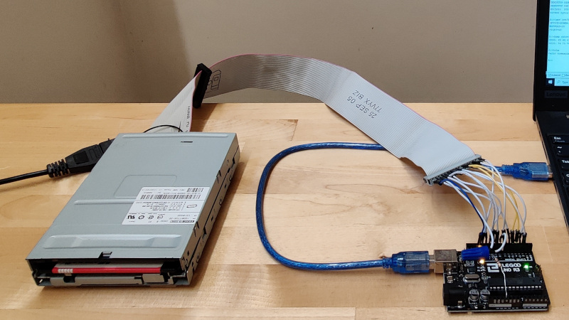
For many of us the passing of the floppy disk is unlamented, but there remains a corps of experimenters for whom the classic removable storage format still holds some fascination. The interface for…
@violet torrent

 meager ore
Hi folks! Just wanted to share some good news about the stability of Circuitpython6.x vs 7.1. Once I upgraded my pyportals to 7.1 thngs have been a lot better. Thank you for that ❤️
Ref: https://github.com/flavio-fernandes/pyportal_station/commit/9949be15c05c11780f8221a4302e0326c33f6921


GitHub
Adafruit CircuitPython 7.1.0 on 2021-12-28; Adafruit PyPortal with samd51j20
Board ID:pyportal
 analog bolt
Any recommendations on groups, Discords, or otherwise communities for small hardware startups? Specifically ppl selling their created products?
delicate quarry
analog bolt
Any recommendations on groups, Discords, or otherwise communities for small hard...
https://discuss.tindie.com/ is the first one that comes to mind?
 delicate quarry
I just realized I have an excess of pic24s from a product development cycle, and they're pretty powerful chips with a pretty nice function set for something that's not completely out of stock everywhere. Has anyone ever considered the possibility of a circuitpython port for any variety of PIC? What types of challenges should I expect if I decide to explore the possibility further?
pulsar shale
What is the default firmware that ships on the Feather RP2040? I guess I can just copy it from the RPI-RP2 drive...
steady gulch
pulsar shale
What is the default firmware that ships on the Feather RP2040? ~~I guess I can j...
I believe picotool can pull the firmware from the drive
steady gulch
pulsar shale
What is the default firmware that ships on the Feather RP2040? ~~I guess I can j...
more to the point though: https://learn.adafruit.com/adafruit-feather-rp2040-pico/downloads
pulsar shale
Got it, thanks!
steady gulch
(FYI if you're curious: https://github.com/raspberrypi/picotool#save) (or want to make a backup UF2 of your whole flash)
pulsar shale
I didn't know about picotool.
 dry fern
Looking at the Adafruit ESP32-S2 boards, they all have a IOxx_DBLTAP circuit with a 1MΩ resistor and a 1µF capacitor both tied to ground. I can't find any documentation on what this is for or when you would use it. I looked in the CPy and Arduino pin definitions for the new QT Py and couldn't see it there either. Anyone know what DBLTAP does?
cold pebble
I recall some early discussions about double tapping a button to get into one of the bootloader modes, but afaict from the schematic and physical (QT Py) board, the xx_DBLTAP doesn't go anywhere, except to a pin on the MCU that isn't exposed in board. But I'm a little surprised if there are extra passives on the QT Py (unless for a future version)
icy moth
cold pebble
I recall some early discussions about double tapping a button to get into one of...
I agree with what you’re saying as I looked and don’t see it going anywhere in the design.
Just kind of there
dry fern
I pulled up the BRD file. It's on the bottom layer, then to a via. nothing is connected to the via on the top side.
cold pebble
the plot thickens... 😉
icy moth
It’s possible that it was meant for a test point but didn’t make it to final
cold pebble
something tells me it's there for a future feature that may or may not get implemented
it's possible that some bootloader outputs there and stores a charge which is subsequently read??
dry fern
The Metro ESP32-S2 has IO38_DBLTAP. It is defined in CPy as { MP_OBJ_NEW_QSTR(MP_QSTR_DEBUG_RX), MP_ROM_PTR(&pin_GPIO38) }, So maybe a trick to not need to connect anything to RX when debugging?
haughty flare
tomorrow is my first day of class so the sylabus is finally available. turns out ill be using a rasberry pi
dry fern
@cold pebble you were right! I found it in the UF2 code.
// pin value long enough for double reset detection.
#define PIN_DOUBLE_RESET_RC 10```I guess now people can search DBLTAP in Discord and find this info. 😉
cold pebble
I don't know what double-tapping Reset does. I use Reset + Boot to get into bootloader. Maybe for boards with no Boot/GPIO0 button (but the Adafruit boards have both). Even the original Saola has both buttons.
oh... if I get the timing right, it does put it into bootloader mode, with a different USB name (/dev/cu.usbserial-{redactedhex}) than Boot + Reset (/dev/cu.usbmodem01) nope, it was a different device
not sure the distinction of the two methods, it appears to the host the same afaict
dry fern
that's neat. Reset+Boot = download mode. Reset then boot = bootloader. Double tap reset = bootloader. Double tap is easier than the reset then boot sequence.
main hemlock
delicate quarry
I just realized I have an excess of pic24s from a product development cycle, and...
As far as I can tell, the most capacious of these only have 52kB of RAM, which quite low for doing significant CPy work (compare with 32kB on the SAMD21 and a lot more or nearly all the other chips we support). You'd want to get a gcc toolchain working, and then you'll need to implement a bunch of common-hal/ to get minimal functionality. Given the RAM limit, I would say it's not worth it, with RP2040 and other chips more available.
steady gulch
cold pebble
I don't know what double-tapping Reset does. I use Reset + Boot to get into boot...
@dry fern Adafruit has been using double-click reset for bootloader on the SAMD boards, but the ESP32-S2 requires that external circuit to be able to detect the double-click, so for example it doesn't work on most 3rd party boards. Personally I find "press boot when the LED is purple" easier than getting the double-click timing right except maybe on the FunHouse where the boot button is hidden and impractical
(correction: purple not yellow)
in fact the reset followed by boot method is not listed in the "Welcome to CircuitPython" guide, which only lists the double-click and the RP2040 methods
https://learn.adafruit.com/welcome-to-circuitpython/installing-circuitpython#for-most-boards-2977081-14
mild prism
@solemn field I received my Adafruit SHT31-D for temperature sensing and my Adafruit Industries LLC 3191 for turning on my furnace. Following these directions (https://learn.adafruit.com/adafruit-sht31-d-temperature-and-humidity-sensor-breakout/python-circuitpython) I am just looking for a little help.

Adafruit Learning System
Ooh, a Sensiron sensor with true I2C!
In the example it is hooked up to a raspberry Pi. (which is my plan as well) but it shows using circuit python and the repl for doing the programming. But wouldnt it just be standard python on the PI? Am I missing something? Is there actually programming on the board itself that needs to be done?
steady gulch
mild prism
In the example it is hooked up to a raspberry Pi. (which is my plan as well) but...
the code is the same, it is using Blinka on the Pi (which brings the Circuitpython API to the Pi), simply installing the driver with sudo pip3 install adafruit-circuitpython-sht31d
(adafruit-blinka is installed as a dependency by pip and provides the board, busio, and other CP modules)
(more info on blinka: https://learn.adafruit.com/circuitpython-on-raspberrypi-linux)
mild prism
Some of this architecture is a little over my head. All the python programming I have done to date hasen't involved any hardware. So the program they show there would be running on the raspberry pi itself? How does it know what pins it is hooked up ot?
maybe im not familiar with the i2c protocall
steady gulch
in this case, the Pi has default hardware I2C pins (GPIO2 and GPIO3), top left: https://pinout.xyz/# which is what board.I2C() inits the I2C bus on
mild prism
oh the i2c is an actual form of communication
I will research more about the i2c protocall
steady gulch
I2C is a serial protocol yeah, you don't need to know the details to use the driver, the basics is that each device has an address, and the drivers use the default address unless you provide one in the constructor, and you can run a scan to see what's on the bus, the Blinka guide has more info on how to use/setup I2C
mild prism
thats the part I was definitely not understanding.
So does the SHT31-D Board need some sort of programming for this protocal or just the programming on the raspberry PI side with the drivers handles it?
Is there any slave programming required for the sensor
thank you very much btw for helping me understand this better
delicate quarry
Nope, the sensor is "hard-coded" to behave straight out of the box (or bag)
You just have to have the right software on your Pi side to be able to read the data correctly.
mild prism
Cant wait to get this project going. My furance in my garage is consuming a ton of propane. Now I can really understand what my actual usage is based on certain set points.
I have a load cell setup as well to actually weight my propane tank
has anyone made any sort of case for the SHT31-D board ?
steady gulch
there are some 3D printable lego-compatible mounts for stemma QT breakouts among other things:
https://learn.adafruit.com/stemma-lego-base-plates
there is that box for the QT PY and stemma boards, or really any board since it uses rails
https://learn.adafruit.com/qt-py-snap-fit-case
pre-made, I don't know
dry fern
I built an enclosure for a Feather, Featherwing, + 2 Stemma boards. However, I mount them outside the enclosure to ensure the microcontroller isn't heating the sensor. https://www.tinkercad.com/things/h0IZhKulBWO-garage-sensor
mild prism
I can 3d print stuff at work no problem.
My garage is just not the cleanest environment. I don't really know if I want the baord to just hangout lol
in the adafruit code example
# SPDX-License-Identifier: MIT

import time
import board
import adafruit_sht31d

# Create sensor object, communicating over the board's default I2C bus
i2c = board.I2C()
sensor = adafruit_sht31d.SHT31D(i2c)

loopcount = 0
while True:
    print("\nTemperature: %0.1f C" % sensor.temperature)
    print("Humidity: %0.1f %%" % sensor.relative_humidity)
    loopcount += 1
    time.sleep(2)
    # every 10 passes turn on the heater for 1 second
    if loopcount == 10:
        loopcount = 0
        sensor.heater = True
        print("Sensor Heater status =", sensor.heater)
        time.sleep(1)
        sensor.heater = False
        print("Sensor Heater status =", sensor.heater)
how would you add the address of the sensor. I am planning to use multiple sensors with an average
sorry. I forgot how to format the code properly on discord
dry fern
adafruit_sht31d.SHT31D(i2c) assumes the default address that Adafruit ships the board with.
steady gulch
(it's 3 backticks on a line with py at the end)
mild prism
Thank you
steady gulch
you just add address=... in the constructor
dry fern
https://circuitpython.readthedocs.io/projects/sht31d/en/latest/api.html#adafruit_sht31d.SHT31D
address (int) – (optional) The I2C address of the device. Defaults to 0x44
mild prism
oh okay so that makes sense
is it possible to change the address so i wouldnt have duplicates?
dry fern
from the learn guide:
ADR - This is the I2C address selection pin. This pin has a 10K pull down resistor to make the default I2C address 0x44. You can tie this pin to Vin to make the address 0x45
If you are using the STEMMA QT connector, you can simply solder a short wire from the VIN to ADR pin. (VIN on the QT port is electrically connected to the VIN pin)
dry fern
mild prism
where do I find this learn guide
In your original question, you posted the link. https://learn.adafruit.com/adafruit-sht31-d-temperature-and-humidity-sensor-breakout/overview
steady gulch
there's a V pad on the back too, no need for a wire
dry fern
steady gulch
there's a V pad on the back too, no need for a wire
even better
steady gulch
I wonder if it changes the address "dynamically" or if the board needs to be reset to acknowledge the change, because if not you could use one additional wire per sensor to activate only one at a time on the other address, so you get as many as you have pins, or maybe the reset pin would allow doing that
that is if you want more than 2
or there is that: https://www.adafruit.com/product/2717
mild prism
Oh perfect i thought there might be another guide I didnt see.
Thats a really interesting concept for having an unlimited amount of sensors
I can probably get away with two sensors to start anything and in the future I will need to add some sort of wireless interface so that will separate my usage anyways.
dry fern
I have 9 AHT20 sensors in the house. Raspberry Pi can get expensive to use as temperature sensors. If you do expand, consider using a microcontroller. like the QT Py esp32-s2 https://www.adafruit.com/product/5325. You can use your Pi with something like Home Assistant to aggregate the data. Or there is Adafruit.io with Wippersnapper.
mild prism
yeah forsure thats what I would do
I just went to set it up and realized that i dont have any header pins for the raspberry pi
dur
mild prism
you guys have any recomendations for header pins for a pi to connect to a bread board
eager bramble
mild prism
you guys have any recomendations for header pins for a pi to connect to a bread ...
Yeah, Adafruit has a bunch. It also depends on if you want to stack things on top of the pi.

Stack multiple plates, breakouts etc onto your Raspberry Pi Model B+ with this custom-made extra-tall and extra-long 2x20 female header. The female header part has extra spaces to make ...
those are nice, can solder on and poke into the breadboard and still put stuff on top of the pi
I would avoid the hammer headers if at all possible.
mild prism
so i just hooked up that application and i am getting a traceback. Value error: no hardware I2C on (scl,sda)=(3,2)
minor crag
I think i'm going to buy a cheap 8 bit arduino, like an Uno
mild prism
valid i2c ports ((3,3,2),(1,3,2),(0,1,0))
steady gulch
did you use board.I2C ?
mild prism
i put their example in ```# SPDX-FileCopyrightText: 2021 ladyada for Adafruit Industries
SPDX-License-Identifier: MIT
import time
import board
import adafruit_sht31d
Create sensor object, communicating over the board's default I2C bus
i2c = board.I2C()
sensor = adafruit_sht31d.SHT31D(i2c)
loopcount = 0
while True:
print("\nTemperature: %0.1f C" % sensor.temperature)
print("Humidity: %0.1f %%" % sensor.relative_humidity)
loopcount += 1
time.sleep(2)
# every 10 passes turn on the heater for 1 second
if loopcount == 10:
loopcount = 0
sensor.heater = True
print("Sensor Heater status =", sensor.heater)
time.sleep(1)
sensor.heater = False
print("Sensor Heater status =", sensor.heater)
I need to find a good through-hole soldered micro controller
mild prism
i get a little confused here:Below is a complete example that measures the sensor readings and prints them every two seconds. Save this as code.py on your board and open the REPL to see the output.
because i am using a pi ot control the board but it almost sounds like it wants to download to the temp sensor board
steady gulch
oh yeah, you need to enable I2C in raspi-config I think
nah that's just because it's written with microcontroller boards in mind
minor crag
hey, can that through hole mounted atmega328 chip on the Arduino Uno handle 5v power?
pulsar shale
Yes it can.
minor crag
i may look into getting an Uno then, desolder the chip, solder in a pin socket, then, theoretically, I can socket a chip in, program it, pull it, and solder it into something else for a smaller footprint
limber grotto
i think it's already socketed
minor crag
i'll have to add one to my list then
limber grotto
you can use an arduino, among other things, to program another atmega: https://docs.arduino.cc/built-in-examples/arduino-isp/ArduinoISP
pulsar shale
Surely there are better ways.
minor crag
it be easier to just program one, pull it off, and stick another one on if there's a socket
some stuff I want to do doesn't require having a full arduino environment built into it.. just some basic inputs, outputs, and some logic
limber grotto
i think you still need some sort of programmer to get the arduino bootloader on, though
minor crag
for example, soon I will build a 6 button arcade controller.. but output will be programmed to work with a Sega Genesis console... 12 inputs, 7 outputs, plus power and ground
pulsar shale
That's a cool project.
minor crag
I mean, if I really wanted to be lazy, I could just get a broken 6 button controller, desolder the micro controller from the PCB, solder that into a breakout board with some screw terminals and be done
pulsar shale
New controllers for a vintage brain.
 teal wadi
limber grotto
i think you still need some sort of programmer to get the arduino bootloader on,...
teal wadi
limber grotto
i think you still need some sort of programmer to get the arduino bootloader on,...
I actually have used ArduinoISP -- It works with a stock supported atmel processor as-is, but it can be tricky to set up
I don't remember the ways in which it was tricky, though; It was a long time ago
minor crag
you're right though.. probably owuld have to get the bootloader onto it.. so I may be better off building a flasher on a breadboard or something
 rough geode
🌐 SPONSORED BY: JLCPCB
Only $2 for 5pcs 2 Layer & 4Layer PCBs,Get $24 SMT
Coupon Here : https://jlcpcb.com/cyt
〰️〰️〰️〰️〰️〰️〰️〰️〰️〰️〰️〰️〰️〰️〰️〰️〰️〰️〰️〰️〰️
👉 👉 👉 FOLLOW ME ON INSTAGRAM https://bit.ly/3kPlAon (PREVIEWS ON THE NEXT VIDEO)
(TROVERAI LE ANTEPRIME DEI PROSSIMI VIDEO IN USCITA)
〰️〰️〰️〰️〰️〰️〰️〰️〰️〰️〰️〰️〰️〰️〰️〰️〰️〰️〰️〰️〰️
🎁 🎁 🎁 🎁...
 humble thunder
latest package of Adafruit goodies came in the mail, that is one awesome bubble mailer this time around lol
minor crag
so, what exactly is the difference between Arduino, Micro Python, and Circuit python in terms of their functionality?.. are they all just different bootloaders designed to run different types of code? Is one lower level than the other? Are they all good for simple, low power stuff or better suited for more powerful devices?
limber grotto
arduino is C++ and is compiled to machine code, circuit/micropy are interpreted and dynamic so they require more resources
for example the arduino uno you were talking about, will not run any python (too little ram and flash)
minor crag
then for what I am doing, I should focus more on arduino since I have a need for simpler codes that can run on lower power hardware
verbal aspen
Note that Arduino is just one possible C/C++ framework, too. There are vendor-provided HAL libraries for specific chips, or you can roll your own bare-metal code, etc.
humble thunder
though Arduino's ecosystem is pretty nice, even if using their IDE is like sitting next to that grumpy old man at the bus stop
tons of libraries available for Arduino to do all sorts of stuff, and if there's a board out there, be it a small low-power board or a big ol' board that's got more processing power than my first desktop computer, they'll almost always have the ability to run code written in Arduino
 lofty verge
humble thunder
lofty verge
humble thunder
the new QT Py ESP32-S2 is 🔥
both in that it's awesome that it's that small and that it runs at the temperature of the sun
steady kite
oh it's based on the esp32 pico d4
humble thunder
What has your favorite Espressif WiFi microcontroller, comes with our favorite connector - the STEMMA QT, a chainable I2C port, and has lots of Flash and RAM memory for your next IoT ...
the S2 isn't dual-core and only does wifi, no bluetooth
pine igloo
how can i convert a double to string type in C?
cloud walrus
pine igloo
how can i convert a double to string type in C?
I would use sprintf. That is if you wantto store the string of ascii characters representing the value of the double like "1234.56789"
pulsar shale
Any pointers for using code.circuitpython.org? When I try to connect I get a bluetooth spinner that never goes away. I'm using the FeatherSense nRF52840.
mild prism
Do you guys have a recommendation for header pins for a raspberry PI to connect to a bread board?
 novel ridge
Something like this? https://www.adafruit.com/product/2029

The Raspberry Pi B+ / Pi 2 / Pi 3 / Pi 4 has landed on the Maker World like a 40-GPIO pinned, quad-USB ported, credit card sized bomb of DIY joy. And while you can use most of our great ...
Also I use male-female dupont cables
If I only need to connect a few pins
If you just mean which headers to solder onto the pi itself, Adafruit also sells these https://www.adafruit.com/product/3662

If your soldering isn't quite up to scratch, or you just don't own a soldering iron yet, then these nifty hammer headers from Pimoroni might be just what you ...
delicate quarry
mild prism
Do you guys have a recommendation for header pins for a raspberry PI to connect ...
Depending on breadboard accessibility, this kit is also a solid alternative. https://www.adafruit.com/product/1989

The Raspberry Pi A+/B+/Pi 2/Pi 3/Zero has landed on the Maker World like a 40-GPIO pinned, quad-USB ported, credit card sized bomb of DIY joy. And while you can use most of our great Model B ...
novel ridge
Oh yeah I forgot about that one
pulsar shale
It's windows 10.
 keen lichen
melissa would have more debugging ideas. perhaps make an issue for it to discuss
mild prism
The Raspberry Pi A+/B+/Pi 2/Pi 3/Zero has landed on the Maker World like a 40-GPIO pinned, quad-USB ported, credit card sized bomb of DIY joy. And while you can use most of our great Model B ...
this is a really nice suggestion
I need a better case too. The one for my pin doesn't give me access to the pins without the cover off
cloud walrus
mild prism
https://www.adafruit.com/product/1989
The cobbler is very useful.
mild prism
i wish i bought one with my last order lol
shipping is expensive here
Do you guys have a recommendation for a little 7 segment display and also some push buttons for a bread board?
delicate quarry
mild prism
Do you guys have a recommendation for a little 7 segment display and also some p...
Most of https://www.adafruit.com/?q=tactile&sort=BestMatch should fit on a breadboard.
novel ridge
I have been waiting for those I2C 7 segment displays to be in stock 👀
They look sweet
haughty flare
for ribbon cables what are the connectors called and do they come in 4 pin?
keen lichen
I think they are IDC
mild prism
If I'm using the temp sensor to a raspberry pi using idc do you know of any cable length issues ? I'm thinking I'll be around 40 ft. I'll probably use ethernet cable as wire. What do you guys think
verbal aspen
What kind of sensor? I2C would have trouble with that length, and analog ones like thermocouples have pretty weak signals that might pick up some noise.
mild prism
Sht31
junior pivot
verbal aspen
What kind of sensor? I2C would have trouble with that length, and analog ones li...
I'd certainly agree, I2C wire lengths more than about a foot can be problematic. CAN bus lengths can easily go up to 40 feet, so I'd say it's either CAN or radio.
 proper escarp
there are i2c extenders: https://learn.sparkfun.com/tutorials/qwiic-differential-i2c-bus-extender-pca9615-hookup-guide/all
junior pivot
proper escarp
there are i2c extenders: https://learn.sparkfun.com/tutorials/qwiic-differential...
I was looking at the spec for that board's chip, trying to figure out if it can run at full I2C bus speed. Says "Compatible with I2C-bus Standard/Fast-mode and SMBus, Fast-mode Plus up to
1 MHz": https://cdn.sparkfun.com/assets/a/5/1/3/6/PCA9615.pdf
cloud walrus

I2C stands for Inter-Integrated-Circuit communications, it's meant for short distances on a PCB or subassembly. But, hey, we're engineers, and we like to push the limits of ...
junior pivot
cloud walrus
Or this https://www.adafruit.com/product/4756
Yes, but for those one likely has to drop the bus speed to 100K. I think it'd be an experiment with any of these to see if it could work reliably over 40ft, nothing (I believe) would be guaranteed. There's a lot of issues (power, capacitance, cable quality, EMF, etc.) at hand.
cloud walrus
Runs with any bus voltage, from 1.6V to 5.5V and up to 400 KHz SCL speed, with cables up to 4000pF. No special firmware, software, or configuration required. Simply plug the power, ground, SCL and SDA connectors into your bus and watch as your rise times magically turn sawtooths into square waves.
But I’m just a software guy…
junior pivot
cloud walrus
`Runs with any bus voltage, from 1.6V to 5.5V and up to 400 KHz SCL speed, with ...
Well, I'd like to believe that would work but in my experience those kinda claims are great but don't always pan out in the real world. Like I said, I'd consider it an experiment until it was proven to work in the specific circumstances of its installation.
delicate quarry
Oh, the PCA9615 works great. I've never pushed it to 40 ft, but I definitely get extra stability on the 2.5ft I run it on, and that's without twisted pairs...
It would be pretty sweet to make a Cat-6 breakout for I2C....
https://learn.adafruit.com/adafruit-ltc4311-i2c-extender-active-terminator/ethernet-breakout-usage but with a PCA9615. If Ladyada doesn't take the idea I might do it...
https://www.sparkfun.com/products/16988 Of course it was too good an idea. Someone already did it.

The SparkFun QwiicBus EndPoint is the fastest and easiest way to extend the range of your I2C communication bus.
pulsar shale
Pretty Pins for Metro M4, is it too much to ask?
mild prism
anyone familiar with the featherwing power relay? I am putting 3.3v to the 3v pin and 0v to the gnd pin but the relay is not switching. Am i missing something?
delicate quarry
mild prism
anyone familiar with the featherwing power relay? I am putting 3.3v to the 3v pi...
Did you close a jumper to designate the switching pin?
mild prism
what do you mean close a jumper
i see there is a signal pin in the middle. I didnt even realize it
oh so i would solder a wire from that signal to another pin to connect to
its working well. Is there a good way to connect that signal to a pin? I soldering in all the header pins when i first pulled the board out
delicate quarry
There should be some metal pads you can just short with a glob of solder
delicate quarry
mild prism
its working well. Is there a good way to connect that signal to a pin? I solderi...
Just pick the pads that correspond to the pin you want to use.
mild prism
oh i get it
thank you that works well now
all my programming is working time to testout my new setup on the furnace
thanks everyone for the help so far!
proper lake
I scrounged around for a tutorial on a circuitpython module for the display, and I am proud to say I am no longer abusing the OLED featherwing by appending layers on top of layers
 stable cloak
Hi, is there a community for people writing rust for adafruit boards? Thanks!
cloud walrus
stable cloak
Hi, is there a community for people writing rust for adafruit boards? Thanks!
There has been some discussion here. This is probably the best channel. Perhaps someone involved will be online soon and can comment.
stable cloak
Thanks! I'm trying to set the dotstar led on the nrf52840 https://github.com/smart-leds-rs/apa102-spi-rs/issues/10

GitHub
I'm trying to use the built-in DotStar led on the Adafruit ItsyBitsy nrf52840. I've confirmed on the pinout that it is an Apa102. I initialize like so. let port0 = hal::gpio::p0::Pa...
main hemlock
pulsar shale
Pretty Pins for Metro M4, is it too much to ask?
We have a list of boards that need Pretty Pins and are moving down it.
stable cloak
How can I factory reset an itsybitsy nrf52840?
minor crag
hmm... i got a 32u4 device today
debating if I want to solder on the supplied male header pins or buy and wait for female ones... If I can avoid breadboards, I do
 daring goblet
I'm not sure who to ask this question, but does Adafruit sell any of their products through Amazon, or is that a 3rd party reseller?
pine igloo
i know they sell to microcenter
cloud walrus
daring goblet
I'm not sure who to ask this question, but does Adafruit sell any of their produ...
I "think" they are all 3rd party sellers. I recall some comments about that in the past. There is a list of distributors here https://www.adafruit.com/distributors and I don't see Amazon on it. For example, microcenter is on the list.
many of the things I see on Amazon are soled by kjdElectronics, which is on the distributor list. You can cross reference them to see if they are a legitimate distributor.
proper escarp
daring goblet
I'm not sure who to ask this question, but does Adafruit sell any of their produ...
a lot of Adafruit products are also available through Digikey
main hemlock
daring goblet
I'm not sure who to ask this question, but does Adafruit sell any of their produ...
We are not an Amazon seller. Some of our distributors sell through Amazon, mostly notably Chicago Electronics Distributors. Digi-Key and Mouser are large official distributors.
daring goblet
main hemlock
We are not an Amazon seller. Some of our distributors sell through Amazon, mostl...
Thanks!
minor crag
so far.. I am liking how simple 32u4s are for what I am using this for
 tawny lantern
What's up fellas
tawny lantern
main hemlock
We are not an Amazon seller. Some of our distributors sell through Amazon, mostl...
Yeah I try to buy stuff of digikey now
I wish digikey had a better ui
minor crag
the only issue I have with Digikey and Mouser is I have to wait until I have a need for enough components to justify paying for shipping
so, some times I just keep a list of stuff I need for future projects and when I have enough, then I buy a bunch of stuff at once
hearty karma
It is possible to get free shipping from Digikey if you prepay your order.
minor crag
well, I don't need anything from them at present
I was considering building an NES or Famicom from scratch soon though.. so if I do that I'll be needing a lot of small parts
verbal aspen
minor crag
I was considering building an NES or Famicom from scratch soon though.. so if I ...
Are chips available for that? I would have assumed the design would involve some custom ASICs.
minor crag
@verbal aspen All components except the CPU and PPU are available... and up until just recently they were still selling new production of those in Ali
verbal aspen
Surprising, but cool... 👍
minor crag
if I do it, I'll probably use those parts from a damaged NES
nevermind.. just found a pair of reproductions (though they're not 100% perfect) for $7.50 shipped, so yeah, if I wanted to do all brand-new I could
thing is, with those not being 100% accurate, and I don't even believe they're in production any longer, and originals degrading so frequently now due to age, it has me wanting to port specifically the functions of the PPU and the CPU to their own, individual, low cost, low power FPGA chips soldered on boards with headers that match the footprint of the original chips, for a direct solder-in replacement
but that has me thinking... the sub $30 FPGA device I use for learning FPGA with.. it can handle an entire NES console being ported to it... one side has 32x2 headers I could directly solder a 60-pin Famicom cartridge slot to.. so maybe that would be more worth the effort
 prime adder
I need to buy an oscilloscope and don't want to 😞
maybe it's technically "I want to buy an oscilloscope and don't need to" 🙂
haughty flare
is there an acrylic case for the large breadboards with binding posts
outer brook
I don't know of one
haughty flare
im considering making one custom as i made an alteration to it that may need custom dimentions. i am putting 2 switches and 2 pots where the binding posts usually go
right now i wish i knew more about laser cutters. i could use one on my ender
proper escarp
a half-decent laser cutter costs upward of $2000
a good one, $15k
all these $400 ones are not worth the money
so .. having a personal laser cutter is justified only if you do a lot with it, and sell your work
otherwise, it is easier to order your design lasercut, say at ponoko.com
 hearty karma
proper escarp
all these $400 ones are not worth the money
hearty karma
proper escarp
all these $400 ones are not worth the money
I bought one of those K40 style ones, because it was cheaper than buying all the parts separately. Then I replaced the controller with an EiBot board, so I could control it with modern open source software via USB. I also upgraded the viewing window, now I'm toying with the notion of adding air assist.
proper escarp
of course, one can turn them into something useful - if you have knowledge and time
hearty karma
I did look at one of the much more expensive ones from a US seller, but it was DOS-only.
uncut summit
Which forum do I post or do I email support about what looks like a defect in manafacturing of couple adafruit products, weak soldering of the usb-c connectors to boards.
prime adder
ok, so it looks like I need to check out the used scope market lol
minor crag
lmao... raked a soldering iron across a finger... sizzled
proper lake
not sure if this is the right place to confirm, but if I'm using a pin on a qt py to power a 3v water pump, I should add a resistor in series to keep current in a safe range because of the V=IR shenanigans right?
limber grotto
which pin?
steady kite
make sure the pin can handle the current, a 3v water pump sounds like it might be a bit current heavy.
it's a motor so i would honestly have a transistor in place to do switching
 upper coyote
uncut summit
Which forum do I post or do I email support about what looks like a defect in ma...
upper coyote
uncut summit
Which forum do I post or do I email support about what looks like a defect in ma...
If you think it was a problem at the factory, then you should definitely email support about it. They can help you to see if it's something you should address or they should replace. Most stuff from Adafruit is tested at the factory before going into stock, but if it's the mechanical mounting of a connector, that might get by. In any case the nice folk at Support@Adafruit.com can help you figure it out.
main hemlock
@uncut summit post in https://forums.adafruit.com, with pictures. We can get you replacements If you write to support they will ask you to post in the forums
then a support person will approve a replacement, if it makes sense, and then you will write to support with a pointer to the thread, saying that a replacment has been authorized
mild prism
Hey guys for this application im working on im using the GPIO on the raspberry pi to turn my furnace on. Im trying to track total on time. is there a way I could monitor how long a GPIO pin is on? A continuous timer that restarting the script wouldnt shut off
cloud walrus
mild prism
Hey guys for this application im working on im using the GPIO on the raspberry p...
take a look at time.monotonic() import time now = time.monotonic() it is a continuously incrementing time in seconds
mild prism
pefect ty
main hemlock
mild prism
Hey guys for this application im working on im using the GPIO on the raspberry p...
you could write a log file that shows on and off times too. Then you have even more information, and if the script gets terminated abruptly, you won't lose data.
cloud walrus
rats -- in cpython it does reset with the script...
cloud walrus
[Clang 12.0.0 (clang-1200.0.32.29)] on darwin
Type "help", "copyright", "credits" or "license" for more information.
>>> import time
>>> time.monotonic()
10.692305542
>>> time.monotonic()
12.808227167
>>> time.monotonic()
14.292287708
>>> time.monotonic()
16.588722708
>>>
jerryneedell@Mac-mini ai_thinker_esp32-c3s % python
Python 3.9.5 (default, May  4 2021, 03:36:27)
[Clang 12.0.0 (clang-1200.0.32.29)] on darwin
Type "help", "copyright", "credits" or "license" for more information.
>>> import time
>>> time.monotonic()
14.12584975
>>> ```but another quick question. Doesnt anyone know if the raspberry PI gpio would turn off if a script is terminated while the IO is on
cloud walrus
mild prism
this is standard python
right cpython is "standard" python -- it looks lie time.monotonic()resets when the script is started. Not like in CircuitPython.
sorry for the bad suggestion.
main hemlock
since it's on a Pi, you can use time.asctime() or many other things to print out a formatted time value. Could make a .csv file with a timestamp and a 0 or 1 or OFF/ON as the second column
cloud walrus
time.time may work ```>>> time.time()
1642354982.612792
time.time()
1642354986.233875
It is the number of seconds since January 1, 1970
main hemlock
datetime.datetime.now().isoformat() and other datetime functions are also helpful, and human readable
>>> datetime.datetime.now().isoformat()
'2022-01-16T12:46:20.069106'
@upper coyote @main hemlock I don't have a broken device but I noticed the USB-C connector legs barely go into the PCB so it's not soldered very well, I have had the connector lift from the board on the macropads, all three I have did the same thing I fixed by put putting more solder into the four post holes for the connector thus strengthening the connector to the PCB.
main hemlock
uncut summit
<@!481746084272668673> <@!329766224093249548> I don't have a broken device but I...
I will pass that on to QA, thanks
@uncut summit I realize you were the one that mentioned it earlier. If you have photos of the pre-soldering condition, and could post it in the forums, that would be great. Otherwise I will just pass it on.
uncut summit
@main hemlock I looked up the connector on digi key and the specs list the legs as only being .9mm while the PCB is 1.59mm thick, I checked anything that uses this connector and it was also the same on the qt-py rp2040 and the feather rp2040 probably fixable by simply letting more solder fill the post holes when fabbing.
@main hemlock yes here first pic is from a qy-py rp2040 and you can see the post holes don't have enough solder, the second pic is a macropad with the connector that got lifted from the PCB

 main hemlock
Could you post this in the forums and I will point QA and others to it. We appreciate it.
uncut summit
@main hemlock I was in the forums, which area? I looked for a particular support catagory and did not see one.
main hemlock
uncut summit
<@329766224093249548> I was in the forums, which area? I looked for a particular...
https://forums.adafruit.com/viewforum.php?f=19 is fine. It doesn't matter too much.
uncut summit
@main hemlock ok
main hemlock
some of the categorizations are out of date
uncut summit
@main hemlock ok posted
main hemlock
tyvm
proper lake
steady kite
it's a motor so i would honestly have a transistor in place to do switching
Ah fair. So the vin pin should be the 3v from the voltage regulator right
haughty flare
They arived!
 pine igloo
haughty flare
They arived!
pine igloo
haughty flare
They arived!
so many!
mild prism
Using Python so you guys have any suggestions for how to modify a parameter in a script or database using a text message ?
verbal aspen
mild prism
Using Python so you guys have any suggestions for how to modify a parameter in a...
You probably will want to explain the scenario a little bit more. You want to send an SMS message to... something? ... to change code running on... something?
mild prism
So I built a application that controls my propane furance in my garage. It tracks on time. Propane usage etc. The only part I'm missing is being able to actually set the temp. Currently I have to modify the script to change the set point
But I foraure want to have remote access. So when I'm driving home I can adjust it
I could make a basic mobile app. But I want something super quick it possible for now
random cypress
That is cool. I'd strongly recommend having the temperature control message channel be more secure than SMS.
mild prism
I agree. Right now this is built on a bread board. I need to switch it from running on a pi to a wireless module that's packaged in a. 3d print because I'm going to put them in ever room in my house. So right now I'm just looking for a quick solution before version 2.0
I would make a mobile app for version 2.0
random cypress
I'm not knowledgeable about the protocols that are best suited to this, but if e.g. you're running a raspberry pi, then I think a simple django site would give you everything you need (incl user authentication)
I hear you on the wanting a quick v1 🙂
The danger there of course is that v1 might work so well that you never get around to securing it
mild prism
Haha
The problem with v1 is the physical wiring ;)
Instead of the wireless. It's a 1 sensor only setup
That's probably a good way to go. A small web server
Definitely not something I know how to do. Lol. Time for some YouTube
 astral roost
why not use a vpn? im pretty sure you can get free/cheap vpn solutions
this way, you can control everything anywhere you are
random cypress
I said django in particular because it gives you a lot of scaffolding right out of the box. Many good options though
astral roost
and your devices arent connected to the outside internet, in danger of being hacked
mild prism
I don't really understand what your suggesting but I am very interested lol
astral roost
im suggesting exactly what i said: a vpn in your home
in the future, if you move to something else, you can just connect to the vpn and access the webpage of whatever you need to access
mild prism
Thank you for the help I will look into that
astral roost
you're welcome
make sure you follow good practices
without the dislike button on youtube, it will be hard to find good tutorials on youtube
mild prism
Do you have a video you might recommend to get me going in the right direction ?
astral roost
one channel i know is networkchuck
but i can't recommend anything, as im not working in that industry
you can try buying a mikrotik switch, as those have a vpn built-in
i think it is free too, and you can find resources on it
but i can't personally recommend anything, as i could be recommending something that's not exactly the best practices
mild prism
Thank you. I appreciate the honest feedback !
astral roost
you're welcome
prime adder
AWS has auth services that are free if you’re doing a personal project sized thing. They also have guides to help you set it all up correctly if I recall
The demo I played with made it very easy to plug in to an existing app
 mystic quest
I found something I have been looking for
https://github.com/petewarden/spchcat
spchcat is a command-line tool that reads in audio from .WAV files, a microphone, or system audio inputs and converts any speech found into text. It runs locally on your machine, with no web API calls or network activity, and is open source. It is built on top of Coqui's speech to text library, TensorFlow, KenLM, and data from Mozilla's Common Voice project.
I got it running on a pi zero 2 and it seems to work pretty well with the microphone or with audio files.

GitHub
Speech recognition tool to convert audio to text transcripts, for Linux and Raspberry Pi. - GitHub - petewarden/spchcat: Speech recognition tool to convert audio to text transcripts, for Linux and ...
 random cypress
prime adder
AWS has auth services that are free if you’re doing a personal project sized thi...
random cypress
prime adder
AWS has auth services that are free if you’re doing a personal project sized thi...
is integrating with their auth service easier than setting up a bare-bones django app? If it is, curious to learn more, as I can't imagine how they'd get an external integration to be that easy
karmic obsidian
The Desk of Ladyada - 5.25" Floppy Drive hacking! https://youtu.be/opCV_4S56Ow

This weekend we dove headfirst into getting fluxengine and our 5.25" disk drive working with the floppy featherwing. good news is that we were able to add support to Adafruit_Floppy and with a little refactoring, add 360K disk MFM decoding. we thought we didn't have any DOS floppies but we did find one in a pile (mouse driver). we then used flux...
jade dirge
haughty flare
50.
Panelized yourself or let the fabrication house do it?
prime adder
Hmmm now that I’m looking through their docs and refreshing my memory, I think it was only easy because the demo had you doing the API calls through another one of their services
If you do it that way, I think you just have to drop a sign in link AWS gives you in the page and configure some stuff and then… magic
haughty flare
jade dirge
Panelized yourself or let the fabrication house do it?
i believe i let them do it
cost me 22 for everything
random cypress
prime adder
If you do it that way, I think you just have to drop a sign in link AWS gives yo...
ah yeah. I see they have a service called Cognito that makes it easy to add Amazon-brokered sign-in to an "AWS app"
prime adder
Yep. So when I get around to doing some stuff around the home like this, I’ll probably set up a web front end that uses AWS services to auth and have an API put messages in a queue that my home server listens in on
 noble sluice
pine igloo
noble sluice
pine igloo
Hello, I am using PubSubClient.h arduino library to publish messages to my mosquitto broker running on raspberry pi,
I am experiencing that after publishing exactly 96 messages, The Arduino stops sending message
i wanna know is there any sort of limit applied somewhere in that library ?
cause it's happening always, not just once
and exactly after 96messages
pine igloo
ok i just dubugged it a bit more and realising that entire void loop() function gets stop after looping exactly 96 times
when i close and re open the serial monitor it starts looping again
or i press the reset button on arduino
very weird problem, Never faced this kind of problem in the past
jade dirge
Sounds like a memory leak
hearty karma
Or a blocking queue/buffer problem.
mild prism
Hey guys, Im looking for a wireless microcontroller thats inexpensive that can run 1 I2C sensor and communicate with wifi to a Raspberry PI.
would this workout well? Adafruit ESP32-S2 Feather - 2 MB PSRAM and STEMMA QT / Qwiic
if so which battery would I buy to run it off of?
mild prism
Lithium Ion Polymer Battery Ideal For Feathers - 3.7V 400mAh
does it use the same connector as the STEMMA QT?
or maybe I would use this instead https://www.adafruit.com/product/4779 Would the 4.5v be to much for the feather?

Here's another addition to our growing family of AA battery holders. Behold! A holder for three (3) AA batteries! It's got a 6" long genuine JST-PH 2-pin cable ...
prime adder
is a 60MHz oscilloscope going to be too low for learning/hobby tinkering? I see the clock speed of an arduino nano is like 16MHz, so this "times 5 rule" makes me nervous... but it could be I'll never actually be able to drive a pin at that speed so maybe it's fine
hearty karma
That's plenty for most uses. You'll be able to see the clock, just not as a sharp square wave (which is fine, it's not a sharp square wave to start with). Most of the stuff you'll be looking at will be much lower frequency. I got by just fine for many years with an ancient 5MHz scope.
This one will barely manage 100kHz, on a good day, with a tailwind, and it's non linear and has a tiny 2" screen. It's still plenty useful, 75 years after it was made.
 delicate quarry
mild prism
Hey guys, Im looking for a wireless microcontroller thats inexpensive that can r...
delicate quarry
mild prism
Hey guys, Im looking for a wireless microcontroller thats inexpensive that can r...
Any ESP32-based dev board should do the trick. This Feather is definitely easier to work with compared to other variants, and will absolutely run what you need it to.
mild prism
is there a more cost effective solution? Whats the difference between the variants?
Would the battery pack (4779) and board (2857) be plug and play with the (4210) connector?
delicate quarry
mild prism
if so which battery would I buy to run it off of?
The Lithium Polymer batteries are ideal; the Feather has a dedicated connector for it, and it comes with all the battery charging and monitoring devices built-in. It's the big black 2-pin connector on the edge of the board, separate from the Stemma QT connector in the middle.
Battery pack doesn't need the Stemma QT cable, only the SHT-31 needs it to connect to the Feather. Not sure if I would recommend the battery pack over the LiPo battery though; you would have to be very careful to not use the battery pack and the USB power simultaneously, as I don't see any means of disabling the LiPo charger...
It could get pretty bad if the LiPo charger tried to charge even rechargeable batteries, as the chemistry and voltages levels are very different, and it would be bad if it tried to charge alkalines at all...
main hemlock
mild prism
or maybe I would use this instead https://www.adafruit.com/product/4779 Would th...
Do not use the alkaline battery pack with the feather, unless you feed it into the USB port. The battery port is ONLY for LiPo batteries
also be careful with non-Adafruit LiPo's. Some are wired in reverse.
mild prism

Lithium-ion polymer (also known as 'lipo' or 'lipoly') batteries are thin, light, and powerful. The output ranges from 4.2V when completely charged to 3.7V. This battery has ...
so you would recomend this?
delicate quarry
@main hemlock Not that I would recommend anyone to actually do this, but the only issue with alkalines in the JST port is the LiPo charger, right? Theoretically, if I were to remove the charger chip, the rest of the circuit should work okay?
mild prism
does it just charge via the USB on the feather?
delicate quarry
mild prism
so you would recomend this?
Yes, or one similar to that with the capacity you want.
delicate quarry
mild prism
does it just charge via the USB on the feather?
Yes.
main hemlock
there are many with different capacities
main hemlock
mild prism
does it just charge via the USB on the feather?
it does, but there are also separate charger boards: https://www.adafruit.com/?q=lipo+charger&sort=BestMatch
main hemlock
delicate quarry
<@!329766224093249548> Not that I would recommend anyone to actually do this, bu...
yes, but check the schematic to make sure
mild prism
okay well I dont want something honky
so I am okay with just USB charging them
How would I go about calculating abttery life. I am going to use an I2C sensor on it. It mentions that in its low power mode its 80 to 100 uA. which is something like 165 days on 400mah battery pack. But I don't really know if it would always be in low power mode or exactly how that works
I would like something that is in that 100+ day range
delicate quarry
The current draw on the SHT31 would depend on how often and how accurately you try to measure, but it should average less than a milliamp of current outside of an alert state. Battery life is highly dependent on how you run it, the 400mAh could last you anywhere from 16-160 days depending on what you tell it to do.
mild prism
i would probably sample the temp every 30 seconds or a minute
main hemlock
The Feather is not necessarily designed for very, very low power operation. Some more recent Feathers allow certain things to be turned off. There are quiescent consumers like the power LED.
From the product page: https://www.adafruit.com/product/5000

What's Feather-shaped and has an ESP32-S2 WiFi module? What has a STEMMA QT connector for I2C devices? What has your favorite Espressif WiFi microcontroller and lots of Flash and RAM ...
Low Power friendly! In deep sleep mode we can get down to 80~100uA of current draw from the Lipoly connection. Quiescent current is from the power regulator, ESP32-S2 chip, and Lipoly monitor. Turn off the NeoPixel and external I2C power for the lowest quiescent current draw.
mild prism
i guess to clerify I would have to take a measurement . Then send it over wifi to my pi
oh shoot i just realized on digikey the 5000 is back ordered until the end of feb
delicate quarry
Oh, then 160 days on a 400mAh is a bit of a stretch. I think you would be comfortable with 100+ days on a 2000mAh, but it would take some optimization for a 1200mAh battery to do the same. Deep sleep mode wouldn't be able to access the sensor over I2C or send data over WiFi.
mild prism
Could I put it into sleep mode then just take it to do the process then put it back into sleep?
delicate quarry
That is standard practice, yes.
delicate quarry
I don't know how the measurements would be affected, since I believe high accuracy measurements on the SHT31 rely on multiple samples and some averaging.
main hemlock
mild prism
oh shoot i just realized on digikey the 5000 is back ordered until the end of fe...
we have it in stock at the factory; do you have to buy from DigiKey?
delicate quarry
There's 84 in stock at Adafruit, you could buy everything direct instead.
mild prism
Sort of. Being in canada its a much better solution. If i buy from the adafruit website it ends up more expensive. Digikey has free shipping and I won't have any duty
delicate quarry
Well, the alternates are a lot less convenient to use, as they either lack the battery port or something else.
mild prism
okay
well then I guess i should just buy direct
the other advantage of digikey is if i order today I generally have it tomorrow
hopefully buying direct better supports adafruit 🙂
delicate quarry
Yeah, Digikey's distribution network does wonders. Support is about the same, but the ESP32-S2 feather is kinda too new to have volume stock...
I can see if there are any other good alternates, even if it's not necessarily Adafruit.
mild prism
which 1200 mah battery did you recommend for the direct connection for the feather?
I have a couple options. I could let the board die more often and just buy extra smaller battery bank to grab from.
sorry i found them in the search
main hemlock
FeatherS2 is similar, made by a third party, not sure it has similar power-saving capabilities. We would refer support requests to the mfr: https://www.digikey.com/en/products/detail/adafruit-industries-llc/4769/13426656?s=N4IgTCBcDaIGYFMCGAXAFggTgZwgXQF8g
mild prism
so something like this
Lithium Ion Polymer Battery - 3.7v 2500mAh
Product ID: 328
I could use the same usb port to chage?
delicate quarry
TinyS2 is also a strong option; none of the alternates have the fancy fuel gauge, but 5029 and 4769 both support LiPo charging, Wifi, and Circuitpython/Arduino.
mild prism
i think i will go with ordering direct just so that I can get the optimal board
delicate quarry
mild prism
I could use the same usb port to chage?
Yes and yes. https://www.adafruit.com/category/917 and https://www.digikey.com/en/products/filter/batteries-rechargeable-secondary/91?s=N4IgjCBcoLQBxVAYygMwIYBsDOBTANCAPZQDa4ArAEwIC6Avo0A should have all of your battery options.
https://www.adafruit.com/product/1781 might be a nice option if form factor isn't an issue.
main hemlock
there are many projects with a case design already you could crib from
delicate quarry
Yeah, it even has protection circuitry built-in, so you can use it without worry, even without the fancy battery monitoring
mild prism
can you show me an example danh?
so I can use the esp32 to actually monitor the current of the battery?
main hemlock
https://learn.adafruit.com/3d-printed-case-for-adafruit-feather but there are lots of projects there that use Feathers and have purpose-designed cases
mild prism
the only thing is the case would have to have alot of vents as im using a temp sensor
Ill probably make my own I have a industrial 3d printer at working I could make something unique
thank you very much for all your help. This discord channel is awesome
So this is what im looking at. Im going to add a screen for my PI as well. I also just ordered the GPIO pi breakout board while I am at it. Any other recommendations to grab while im making an order?

the male headers are just for testing in the future. but that 4210 should connect SHT31 to ESP32 feather right?
the order keeps getting more expensive lol
 agile zealot
Does anyone here do Game Jams using CircuitPython? I'm getting into displayio and it made me realize that I'd love to see all that cool games people make in that time limit. I'm considering trying to do one later this year, so there's also that. 
mild prism
Does adafruit have 3D cad for their board? iges step solidworks?
agile zealot
mild prism
Does adafruit have 3D cad for their board? iges step solidworks?
They do for a lot of their products! You can find their CAD files here: https://github.com/adafruit/Adafruit_CAD_Parts

GitHub
CAD files for various boards, components and parts - GitHub - adafruit/Adafruit_CAD_Parts: CAD files for various boards, components and parts
You can download the repository as a ZIP file
I believe there's almost always at least a STEP file, and it looks like there's typically also F3D files as well
F3D is Fusion I think but I only use Creo professionally and OnShape personally 😅
mild prism
hmm i dont see the PN 5000 esp32
Btw I have to tank you guys again for all your help! This discord is really amazing.
thank**
Maybe im looking wrong
I dont see the PN 2857 SHT31-D Either
delicate quarry
It doesn't include parts for every Adafruit board, unfortunately. I imagine the ESP32-S2 feather will be added in the future, but it's never been an all-inclusive list.
agile zealot
mild prism
no problem I can just measureit quick and draw my own rough cad
Since the designs are open source, you can at least find the PCB files for things like measurements. If there's a Learn Guide associated with the product, you can find things like that in the "Downloads" page there. Here's the PCB file for P/N 5000: https://github.com/adafruit/Adafruit-Feather-ESP32-S2-PCB

GitHub
EagleCAD PCB files for Adafruit ESP32-S2 Feather. Contribute to adafruit/Adafruit-Feather-ESP32-S2-PCB development by creating an account on GitHub.
That will at least help with not having to measure overall dimensions!
If you're a Clankie like me and PCB files make you cry, the Learn Guide for a product (if it exists) typically has it as a picture with dimensions:
https://learn.adafruit.com/adafruit-esp32-s2-feather/downloads
 mild prism
@agile zealot I see the board layout in the learn guide. Thank you very much
mild prism
For the ESP32-S2 does anyone have an example of how the wifi would work? I've never done any wifi programming before. Looking to send data between two scripts (one on a PI)
unless im missing something I don't see it in the learn guide
delicate quarry
mild prism
For the ESP32-S2 does anyone have an example of how the wifi would work? I've ne...
https://learn.adafruit.com/adafruit-metro-esp32-s2/circuitpython-internet-test is a good place to start. The board may be different, but it's the same core chip and code.
mild prism
thank you that looks like exactly what I need
here is a more general question:
If i have a esp32 collecting data from a sht31 sensor. Then using a raspberry PI over WIFI to use the data to accomplish something. Would it be good practice for the ESP to write to some database or file on the raspberry PI then have the PI read the data? Or have some script on the pi that receives the data directly then decides what to do with it on its end?
Keep in mind I am planning on using about 20 esp32/sht31 combos
with 1 Pi
pulsar shale
Sounds like you want to use MQTT.
delicate quarry
I would second that recommendation. @mild prism you can look into Mosquito MQTT broker for Raspberry Pi, which essentially sets up a server on the Pi to manage all the messages from your ESP32-S2s. Then, you can setup your ESP32s as MQTT clients to publish data to your Raspberry Pi broker and manage the data that way.
mild prism
oh man this sounds over my head lol
is a mosquito MQTT a software or hardware thing
Oh I see a bunch of documentation. I will look into that option thank you
I see what it does and have a rough idea of how it works. But how would this be different efficiency wise then using something like an sql database and updating and reading a common field? Im not trying to argue. Just trying to learn more about good practices and understand what makes certain things better. I am still quite anew programmer.
delicate quarry
mild prism
I see what it does and have a rough idea of how it works. But how would this be ...
This is separate from a SQL database. Strictly speaking, this is management of how data is transmitted, not how it is stored. In practice, an SQL database may be used in conjunction with this MQTT broker to store the information received from the clients.
MQTT is a communication protocol, not a database.
mild prism
oh so the MQTT is how the information is sent over the wifi and received in the PI. Then from there you would store it somewhere
main hemlock
you could also send from the ESP32 directly to an MQTT could server on the internet, like adafruit.io
mild prism
but couldnt you just do a SQL query right from the ESP32 to a remote database on the PI? I'm trying to understand better lol
I want to make sure going from the sensor to the PI i dont require any outside connection. So if my internet would go down everything would function still
mild prism
The more I read the more it seems to be a huge bandwidth savings and managing platform?
delicate quarry
mild prism
but couldnt you just do a SQL query right from the ESP32 to a remote database on...
You could, but because wireless communication isn’t as stable as wired, transmitting minimal data for maximum information is an important factor.
None of this has to go to the World Wide Web if your setup is designed to transmit over your local network.
As long as your clients (esp32-s2) and your server/broker (pi) are on your local network, all the messages transmit through your router, but never through your internet gateway.
pulsar shale
It would also isolate your database from your sensor network. If you change your database you would have to update all the sensors. With MQTT you just have to update the broker.
mild prism
Okay. I will do it ! You have me convinced lol
It doesn't seem to super complicated but hopefully I know enough python to pull it off lol
But I guess this is all about learning ;)
agile zealot
Chiming in late, but if you're open to using Bluetooth, there's a library that uses it to send sensor data to a Pi that then uploads it to AdafruitIO. If nothing else, just some extra code to check out! https://github.com/adafruit/Adafruit_CircuitPython_BLE_BroadcastNet

GitHub
This is a simple BLE broadcast based sensor net. It is not secure at all. - GitHub - adafruit/Adafruit_CircuitPython_BLE_BroadcastNet: This is a simple BLE broadcast based sensor net. It is not...
Good luck either way!
mild prism
Sadly my range wont work for bluetooth
but i appreciatethe thought. I will look at the code.
delicate quarry
Esp32-s2 has no Bluetooth to make use of this, either. You would need to use a different board…
steady kite
something interesting i noticed.. there is a electric fence around the house.
everytime it triggers the clock in our kitchen does as well.
it's in perfect sync
 hybrid bluff
Hi my my raspberry pi zero wh keeps overheating and almost burning me what should I do
verbal aspen
hybrid bluff
Hi my my raspberry pi zero wh keeps overheating and almost burning me what shoul...
You could add a little heatsink: https://www.pishop.us/product/aluminum-heatsink-for-raspberry-pi-zero/

PiShop.us
American Raspberry Pi Shop. One stop shop for all your Pi needs. Raspberry Pi add-ons, HATs, accessories, Starter Kit, Media Center kit, RetroPi Arcade kit, Ultimate Kit, and many other project kits. PiShop.us is approved Raspberry Pi re-seller and carries all official Raspberry Pi boards and products.
humble thunder

For when you need a breakout right now and not in a few days
Only thing is that you have to be fast with the iron or the plastic gets sad lol
humble thunder
oooh, new product idea: MicroSD QT Py BFF, a little board to fit onto a QT Py that just has a MicroSD card slot on it wired in SPI mode
 winged sphinx
Anyone participating in the Growing Beyond the Earth challenge from NASA?
teal wadi
steady kite
something interesting i noticed.. there is a electric fence around the house.
ev...
How exactly is the clock “triggered”? Does the alarm sound? o_O
steady kite
no when the electric fence triggers the EMF trigger the clock 5 m away
the timing is 1:1
verbal aspen
He's asking what you mean by the clock "triggering"... does it reset to 12:00, does the display flicker, does the alarm sound, etc.
teal wadi
I think they mean that the clock "loses time"
In which case I would agree with @outer brook, in that it measures time based on the AC frequency, and slight changes in frequency can impact the clock
Microwave clocks, flip clocks and similar devices tend to use AC power as a timing source