#Ender 5 To Mercury One.1
3635 messages · Page 4 of 4 (latest)
thanks! I almost do this for a living, with the difference that I’m doing 2D plots instead of 3D models 😂. so the programming tool it’s something I’m comfortable with, instead I simply get lost in all the possibilities of drop down menus, and buttons 🤦♂️. But this is basically tinkercad on steroids, once you forget about graphics interface. few basic shapes, add, remove, group…
it didn’t print flawlessly as I have some warping here and there, the slightest warping makes some artefacts in the top layer, I don’t know if there are settings to mitigate it
anyway, this is a preview of what the door bazel would look like

@proud cliff where is your beta rank???? #1128770268240814240
it will probably take me forever to find affordable extrusions, is it ok if I take forever for the build?
hell I just applied, I was really torn, but at least I have an idea/budget for the bom
@proud cliff #1069710972303982662 message
check this might help, Portuguese though, I believe you may be able to read it anyway
still sick, this summer sucks, plus it seems Denmark is on the other side of the AC compared to all Europe, here is cold AF... but let's quickly send this

this is what’s on top@of my printer right now, it will make for the best resonance interfering scenario


it was only 16:20 thought, so I was under the 15 min only for the slicer
@proud cliff what speeds accels
30k 800
maybe I should have increased the accel and decrease the speed it goes max 300 anyway
yes
but with Orca, is a more verbose slicer, I might have to chase something to turn off
and make sure you don't have minimum layer time
I don’t have retraction and no min layer time
got a lot of help on annex server for settings
my 14min one was with 5 perimeters (way too much)
Speed bency test, it took ~16min and 20 seconds.
It was sliced with OrcaSlicer
I’ve ordered some microfit from replimat.eu . I had no idea about their shops, they also have other 3D-printing related items, at reasonable prices

Those prices seem reasonable, based on what's in there.
I'd pay that, as the included pins double the value.
yes, by price-per-unit I might pay less by taking a bigger kit, but I’d have the same amount of 2-3-4 pins connector, which are the one used the most… I’ll get a kit eventually, but I’ll keep using jst when 2A can do and the microfit above that
This all makes sense to me.
I still have a massive sinusitis, it’s really really hard working on the printer. I’d never thought I’ll get so old so fast
ohh age gets us all quickly
I'll be 40 in a few months. sigh
I'm just 5 years behind
I’m 4 years ahead, it’s not too bad, you don’t even need to drink to get an hangover, you just eat the wrong thing and it’s like you’ve partied till morning (just the sh*tty next day, not the actual fun)
I’m 40 in a month and a half
I was out late last night and it wrecked me
You must have a healthy diet normally, the key is to eat bad food all the time and your get that iron gut that is fine with anything.
wait I'm the youngest here?
Yes
I wanted to hide my dismal cutting of the back panel around the motors, so I designed a simple frame to go around it

but unfortunately I’m not very good at measuring either, so I need another iteration. height it’s fine, the width I can go much closer to the motor tower

Also, I see why 3do was selling this roll of red in discount, as spare parts
and I need to reduce the height-fillet in the internal cutout
after learning the existance of hueforge, it gives a whole new priority on wiring, configuring and setup the tradrack. Even if I’m half incapacitated I’ll try to have it working this week 😛… although I don’t have a windows computer
nor any calibrated filament
Manual filament swaps are not that bad with hueforge prints
4 color print will only have 3 swaps
isn't hueforge for mixing filament like a regular inkjet printer?
kind of, but you mix the color within different layers, you print very thin layers swapping colors at a given height and the results is a color picture
oh had the idea it was on the hotend level
that’s why you could do it manually, because you swap 3 or 4 time filament during a print, at the end of a layer, the printer pauses (well you have to set it up to pause and keep hot) so you can swap. not mid layer, is amazing
that was the da vinci printer… inkjet mix on the filament.. a flop?
Check #print_showcase to see the one I did recently
I am just too lazy and clumsy to do it manually
no I thought it was a mixing hotend saw some concepts a long time ago
I'm printing a dementd camera mount system I cam out with....

I've spent.. well too much.. in trying to make a function that would create a nice angled (2 angles parameters) object, well I can't, the 45 degrees seems to be barely printable, so let's see if the system works, there are 3 components, a wall/etrusion mount, the angled element (the one above) and the camera mount, they lock within each other, so if I need a different angle I only need to reprint the angled part
I’ll be damned, I retried, with less infill and boosted to 200% on mainsail (just because I wanted to approach faster when it failed before) and now it did print this ugly stuff
they bind to each other pretty well. it’s quite bulky and ugly, and the 45 deg is probably useless unless I mount the camera pretty high. but it’s my fist attempt

I probably could do 20x20 cubes, or even 20x10 volumes instead of 30x30 cubes
I should probably look what’s wrong with all those random under extrusions
That's an interesting approach 🧐
I want a fixed mount, so it’s set once forever, once I find the perfect spot/angle
I like it. What about a rotating/locking mechanism for fine tuning?
hehe, it could be, the middle element (the angled cubes) could be whatever you design it to be
but as you can see my cad skills, even when brought to the familiar element of programming, are not great
It's a practice thing, my dude!
it kind of does what was meant to, mounted very very high it’s not bad, I could even use that odd slots between the 2 cube as cable path


this is the original camera

I need to move my Camara back down... I put it as high as I could and hate it
I can imagine, I like the low front position as i can see very well the first layer (depending on the light). Hig-front-right, as it would be now, I still have limited sight on the bed (some corner is still blind) but I can see more of the printer in general, but less detailed 🤔 . I'm printing another 45 degrees on the x/y plave and 10 degrees down on the z, aiming to mount right above the tensioner towers
I seriously need to rethink this middle angled piece

Wait, what am I looking at here?

it's the chamber thermistor and the neopixel wires, I am still looking for alternative way to reach there, before it was coming from down, but I didn't like it
the camera, attached to the ceiling, facing 45 deg down looks like this

STOP ZOOMING IN, TURN THE OTHER WAY!!!!
If anything, you should be zooming out
Uh, isn’t that what everyone does? 😆
well, I like being criticised, as long as it’s constructive. it’s not that I have a pristine build here, there are a lot of loose ends I need to tackle (however I am surprised how well this machine is working). I was thinking to use the zip-tight on the motor mounts to pass and clean up some cable, so far I only pass by the cable without any zip tight 🫣
camera on top: +cons) I already feel the need to go and check if the nozzle is clean. from below I could see if the print was starting with some extra oozing, and I would order it to pass few more time on the brush
That wasn’t much of a criticism, more of a tongue-in-cheek.. so, don’t take me seriously on this regard
from the top it’s totally hidden
I guess, I know few people from Israel, and they all kind of have the same engaging/curiosity/border-line criticism all the time 😅, so I think it’s also a cultural thing, which I understand and embrace 😜
You can’t blow my cover like this 😲
ooops

don't destroy me though 😰
You forgot to peel before assembly
I have no clue of what I'm doing, so criticism are a way to learn...
and I still see the plastic
ohh jeez, don't remember me, I am a moron
lol
I have this phobia of peeling things, feeling that after they've been peeled off they are used and old :P... well so I waited to peel off until too late
learn to edge peel then
that panel it's also extremely soft, I don't know what material is it, but I could scratch it with my fingers, behind there is a 5mm plexiglass and some wood. So if I use some tool to remove the plastic it scratches quite a lot. I Think I have to loosen up the bolts and remove where possible
is it porous lookking on the edges?
kind of

it’s quite rigid for its weight
its cheap and easy to work with, can be cut witha knife
Inuse it for insulation, mainly
can also be bonded with plumbers pipe glue
ohh, nice to know!
just look for stuff that made for PVC pipe
and its a chemical bond, melts the platic
I have found a couple of 1m2 panels in the scrap basket in the local hardware store, so I grab them, thinking I’d use them for something
they were perfect to cut around the motor shapes, as you said, extremely easy to work with
I feel this is much better, right on top of the tensioning tower, 45 degree in x and -10degrees on the y

it misses the toolhead by a ~5mm during the ztilt 😅
this is how it looks on camera

I rarely print objects so wide to spans to the hidden corners
I need to move the lights higher thought
hmm, maybe I need 2 cameras 😅
front center pointing down too high?
New camera location looks good, though
I don’t want something to stay in the way in the middle
I was thinking to buy a new cheap camera and have a top-rear view as well, so I see all the bed… but I loved so far with my camera moving and pointing in random directions (occasionally aiming to the printing area) so I think this low-side view is good enough
🤯
figures out you can make a 2D shape into 3d by extruding it... I should really work on my stuff instead of this 🤦♂️
It captures the important bits 👍
Playing instead of work? 😆
hard to work, everyone in in vacation but me... not that I risk doing anything productive anyway, but it give the extra excuse to hyper-procrastinate
but can you believe that this code ```python
from muscad import Union, Surface, Circle, Square
spade = (
Union(
Surface.free(
Circle(d=20).align(right=0, back=5),
Circle(d=2).align(center_x=0, front=35),
),
Surface.free(
Circle(d=2).align(right=5, back=0),
Square(1, 15).align(left=0, back=0),
),
)
.x_mirror(keep=True)
.y_linear_extrude(10)
)
gives you this!

I didn't know the Surface thing, nor the extrude thing, so hopefully my designs will improve now 😛
The more you know...
heh so you can basically do the same as fusion or solidworks but in code
sketch, extrude/cut
Realizing that Fusion sketches are just a system of equations made my head explode.
SW doesn't seem like it
but it knows when the sketch is fully defined
which is sometimes confusing for me as I don't find the reason to be under defined
thinking of building ome of these as well https://github.com/FaqT0tum/Orbion_3D_Space_Mouse

GitHub
3D Space Mouse DIY easy to build at home. Contribute to FaqT0tum/Orbion_3D_Space_Mouse development by creating an account on GitHub.
after I'm done with my loooong to-do list
I've heard great things
why is there an Italian flag/tri-color under the name? 🤔
I noticed that, too. 😆
Because the author is Italian
so this is the actual camera picture with the camera mounted in (before I was holding it by hand). I’ve printed a couple of things and I don’t dislike it. unless something awful happens during x/y homing and I can’t see it, but I will notice if the nozzle is off for the sexbolt

this stuff? (I had it for some pool plumbing working)

yes if turtle says its expanded PVC and that's PVC glue
PVC glue has a somewhat nice smell btw
I’d found out how well this stuff bind with he glue
I love pipe glue smell
any glue/solvent/alcohol/whatever
deep sniff
I hate to make the party crusher, but you know it’s not healthy, right? kids-who-reads this (plenty I assume) don’t smell that stuff!
yes I know it's not, I do it anyway
a long time ago got really high with that stuff while helping my father glue the pool plumbing
"Dad, can we glue another pool together! It was a great bonding experience!"
in multiple bonding ways 🤣
few more endstops

My wiring of the tradrack reached new lows, even for me. I’ll make it work and than hopefully I’ll get the microfit that are supposed to work with it… and clean up the wiring. hopefully it’s not one of those things that start as temporary and than last 2 years unmanaged
very roughly set up, I am still waiting for some microfit to wire the endstops and the motor on the carriage as it’s supposed to, but it works! I can switche filament with just few console lines

I was thinking to implement a complicated filament cutter, but after seeing how well the tip shaping works, I don’t need to, it’s perfect!
cost of this thing: ~30€
vs the cheapest ERCF kits that was ~100€
tiny

Since hydra I always had this loud z click.. it works fine, and I have a tons of another thing to look at… but today I looked a bit further. it’s an oldham coupler doing its thing. maybe some grease wouldn’t hurt
but I think I’ll replace the screws to tr8x2, If I find some
at the very least replace this one
what am I’m talking about, I have a spare tr8x4, although it’s 370mm and all 3 hydra are 350mm 😖, but I think this screw is the cause of an artefact in the benchy bottom. (it’s the top right screw)
this artefact is present at any speed I’ve tried, even slow

I also realised I can’t use multi color, since I don’t have enough spool holders, I only have 1 reliable roller, in the filament dryer. I am planning to use the ender 5 vrollers to make some more
the bearings of the vrollers
for now the teadrack is a glorified filament changer tool (amazing to be able to request to unwind the filament from the toolhead, using the console 😛)
I'll have the same issue
there are a few fully printed spool holders
I will get a 10l ikea 365+ box and make a drybox for 2 rolls
I know it will not be perfect, but the filament might stay dry a little bit longer, humidity is killing my filaments this summer
for my use case open air is enough
@frail swallow I need some help on microFit 3 😓, I almost lost my sight trying not to bent the front pins, and now they can’t fit into the connector… they were better looking before, now I bent and squished already trying to fit them.. what’s wrong with them?


Gimme a sec to take some pics
they go almost all the way through, but I think I’m missing a couple of mm to get the click, and stay in the connector
looked on youtube, and it seems the easiest thing on earth… and it wasn’t difficult to crimp.. just they don’t go in 😡
take your time, I probably need to make it rest until tonight… edit and thanks already 🙏😖
Take a break if you're frustrated. Frustration makes things much harder.
I'll take some pics and show you what the deal is and how to fix
especially since when your frustration ends, the metal pins are going to stay all bent and ruined 😛… better to d it right
ah, but you could see something is wrong in mine? good to learn because they are the first 4 of ~50 that I have to crimp over the weekend
also, this is probably a task I need to to without contact lenses, they make me slightly farsighted, without lens I’m super shortsighted… and that’s what I need right now
Here we go. Incoming.
So the problem are the "wings" that grab the sides of the connector socket. In the third picture, it's the dark area on the sides.


I feel you, without contacts for sure
Those "wings" enter far enough to clip in. I figure you know how this works, but it's some background.
add astigmatism to the equation ant I can't see shit in any way, need a damn magnifier
Good pin (blue) vs. bad pin (black). See how it looks asymmetrical?


sure, but it’s far more complicated that jst this thing, so go on with the details
On the black wire, the one pin is correct while the other is bent too far in. This is a recycled pin, btw, but it can also happen during assembly (as in your case).
hmm, wow, that’s some minor detail
so I should bent them more out?
I think I tried, but the pins doesn’t go all the way in, I think
I have the Molex tool, but a SIM card extractor or other fine probe works just as well. Push into the connector, then nudge it upwards to bend the wing outwards. This is easier than trying to pry from the outside.


I gotchu for that, too
When the pin does not snap in place (more common with these than the socket pins):
- Make sure your orientation is right!
- Use a SIM card probe or something else very fine to push it in place. Some force may be needed.
If the pin is angled at all, it will not slide in place!


I was thinking it was the “top” pins that have been pressed a bit. I use pliers and tried to push quite hard…
wait a sec… am I using the wrong case?
Also, the "guides" that hold the wings are important. If they get bent, you wont be able to insert the pin. You can straighten them sometimes.

I think that what happened to me
I can't make out enough detail in the pic, but it does look like that may be it.
Discard the pin if it's pretty damaged
this are for the male pins?
Uh...I never know which is male and female. Something plugs into both. They're hermaphrodites to me. 🤣

NEGATIVE
the other one?
Snap connector uses socket pins
🤦♂️
(Like I said, I don't know which is male and female 😆 )
so maybe that’s why I couldn’t fit them
No worries, dude. You've never done this before. 🤷♂️
hopefully now I’ve placed in the right slot 😂
thanks @frail swallow , to put up with such newby such me
now that I think about it, female connector has female pin
no wait
opposite
male connector, female pin
lol, you're good, dude. Mistakes happen.
This is why I stick with "pokey pin goes in the panel connector, socket pin goes in the latch connector" 😆
a lot longer than F in M, M in F
it's the opposite basically
latch part is male, panel is female, pins are the opposite
I think is the same in jst, it’s just that I didn’t know which was what, I google it and I might have looked at a wrong image 😅
true
conversion from jst to microFit for the toolhead ~ 90% completed. I need to crimp the heating cartridges back to microFit (yes, I cut and crimped jst so far). I know, JST it’s only rated 2A, but after the initial heating I think 2A is fine, and it’s not going to melt for 30 sec at 3~5A… but yes, microFit is safer, end of the story
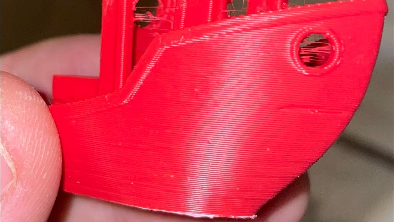
crack! 🤦♂️, but it still holds, I have to go back and revisit the slicer suggestion for this part, the bridges seems to be too thick

rack?
yep
backpack has been zip tight, it only needs a lid (which I’ve cut, but it was 1cm too short 😫)

closing the lid
look at you with fancy latches
probably the fancier thing in the printer… I basically did the all thing because I wanted to use those 😝
Beautiful.
sealing the backpack considerably reduced the noise during printing
I added this small cover to protect the filament runout switch on the sherpa mini

So, @frail swallow , summoning again with questions about molex stuff. I like the sturdy miniFit jr in the ebb42, but, If I want to swap canboard (eg testing again the thr) I don’t want to remove the connector. so doing a pigtail on the thr would be the best solution. but the MiniFit jr male connector seems to be mainly a pcb type connection, is there any compatibility with this type of thing for a pigtail?
Yeah, the THR has screw terminals, yes?
Here's a link to Amazon.de: https://www.amazon.de/-/en/Mini-Fit-Connector-Components-Kali-2404-Industrial/dp/B07XJYMQ1Y

With the Molex Mini-Fit Jr. Plug set of 4 pins process a high-quality plug connection. Thanks to its small dimensions, it allows installation in the tightest of spaces. Thanks to the special coating process of the pin and socket contacts, a clean Transmission guaranteed when processed correctly.
huu, thanks!! 😛 that’s exactly what I needed. I couldn’t find it, but now I do 😒. sorry to disturb you with such silly stuff
lol, not a problem at all
I like the color of that set, actually. I wish I could find that color locally.
but wait a second, ATX is basically Mini-Fit jr?
AFAIK yes
Yep, that's what it is.
I might have something at home, I doubt I’ll ever need an IDE disk reader
I have this old disk converter that came with a bunch of atx plugs
Thinking about splicing?
Or recovering the connector?
4pin there's the 12V connector for motherboards thathas those
but I can’t find it, so problem solved. I have to buy new one. it’s so expensive that is the same if I buy pre-crimped cables 😒
minor incident nozzle-bed collision, resulted in me trying to straighten the neck of the bambu clone hotend, resulting in actually breaking the thing
so now I'm back to rapido, also swapped the sunon 4020 for a gstime 4010, definitely noisier, but looks better

luckily I mangled the cf side well before this already
the joy of beta testing stuff 😓
for some reson after the pause the printer goes way down, the z-offset is left unchanged, and the z position is still 0.25, but mainsail screen recording clearly shows something funny
this is the same thing that made me destroy the bambu, so it’s clearly getting expensive
it seems to be messing up the mesh
I need to check how much those rubber tiles actually weighted, I’ve lifted (as much as I could, like 10cm 🥵) the printer while I was on a scale - I felt the scale dangerously giving in- I should also lose some, myself, but the printer was a big component, 40kg!
@frail swallow I hope this to be a cheap knock off of MiniFit jr 😅

The knockoffs generally work, IME. Sometimes a little trickier, but they work.
So, update on the stagnating build, the printer itself works perfectly, I am focusing on the multi material unit -despite my initial thoughts of postponing a buffer, I really need one, tangling loops everywhere even with short bowden-
left unfinished are the door and the camera mount
and I also have a cooling/refactoring of the elbay afterward, and it’s done
almost done
since a couple of months 😅
Instead, I ordered 3 new tr8x2 leadscrews. the current ones are 8x4. And I’ve noticed a frequent falling on the rear when the motors are off. once it even prevented to home, as the two front were end of the rail and the back was to low to touch the endstop. I’m still unsure why it didn’t push it up anyway.. hmm, thinking about it, I should change the z motors as well. I’m still running with ender 5 crealitys
suggestions for good/cheap motors for the Zs?
actually I never looked at hydra bom if they have motors suggestion
they have just get smaller LDOs
or whatever really
mine is running on 3 dfrobot ones cost me like 13 or 15 each
40mm steppers oughta do it. The Creality 32s might be undersized.
Yeah, the BOM links to 1.5A 39mm steppers, StepperOnline 17HS15-1504S-X1
hmm, amazon in eu 5x 17HE19-2004S for 47€, or 3x 17HE15-1504S for 27€. probably the 27€ is the wiser choice, but I wonder if I could use the 2 spare in a future build/decent spares for the a/b
hmm I see though it’s the economy version, wich is on tier description worse than the HS serie (or HP)
but how the SO hs serie would compare with 3x creality 42-34 I currently have
probably better anyway 😅
but on paper the hold torque is very similar, 40Ncm for the 42-34 and 45Ncm for the SO 39mm. and I have the 42-34 on 0.58a (1.5A peak current), I’ll try to see if 0.85 is better, and I think I should look at the screw rather than the motors
I didn’t realised the creality motors actually have decent specs. It sounds suspiciously good, if they burst in flame I’ll know it was a bad copy paste from somewhere else
hmm, unclear, some place says the max current for the 42-34 is 0.8A, some other says 1.5A. 0.8 is more believable, so I’ll drop the current instead of increase it
Creality's 42-39s are lower peak current than SO, IIRC
So well, it all started with a loose magnet in the klicky dock, than a magnet came loose from the top of the probe, than dumb me pouring to much glue in the magnet slot so the magnet couldn’t conduit the signal from the switch, than me like an ogre trying to remove/ reworked/unglue it, than basically I killed the switch… well, hopefully I printed a spare klicky probe and store it somewhere 😓
especially the probe, it’s something that can stop working at any moment and prevent you from printing
I know the z offset, so if I manage to til correctly somehow, I could print a spare
getto style fixing the broken klicky, found an old mouse at work (I didn’t want to sacrifice a good endstop since I potentially going to leave it in a half broken thing…)

I’m going to print so many spares probes and docks from now on, that I’ll keep finding them around everywhere
given that I manage to make it print again
the issue with the switch from the mouse is the short pins
soldered some wires into it… let’s see
f*%k yeah!
dock and undock okay for a couple of times, I only need to print a good one now 😅
It feels so good yet so bad making parts do their job to create a part that will replace them as they are redundant.
but I’ll keep it in the drawer… you never know
I had to drop my switch offset from 0.46 to 0.03. how much did I squished around this poor probe
I’ve printed the unklicky 6x3 magnet version and the heat insert version. I think the HS version is the most polished one, but it looks considerably beefier, it could be good for a volcano nozzle as well though. which version are you running?
I’m running the NG-BFP but have the normal BFP with the magnets glued in for extra security for my next toolhead. The NG can’t pull up and line up properly as the magnets are covered. I’m using it with stealthburner and will be using it with micro mantis when I switch to that.
well fuck unklicky can't make it work
3 different wires all too stiff, works one time as soon as I push it no longer goes down as expected
without the magnet attached to the wire works fine
unklicked

it docks a bit awkwardly, and remains slightly tilted up, but it seems to work
probe accuracy is comparable to klicky ```yaml
probe accuracy results: maximum 18.586250, minimum 18.557500, range 0.028750, average 18.559562, median 18.558750, standard deviation 0.003054
500 samples 10mm/s with 0.5mm of retraction between probes
I had to adjust the switch offset, from 0.03 mm (the badly mangled klicky) to something close to 5mm. the probe is around 8~10mm taller than klicky from the values I see in the console
Unfortunately I don’t have the uhf kit, otherwise I could have tested @solar bridge volcano duct… What if I only put a volcano nozzle without adapter using the hf silicon socks? 🤔
27€ for the uhf kit 😩
If you can order from 3djake without paying a fortune for shipping it's 19€
hmm, shipping might be 6~8€ if I’m lucky, so there you go. but I’ll check it out. I was filling my basket at 3do.dk. where I usually get stuff with 1~2 days delivery
If you get 2 e3d volcano nozzles with it you should be over 50
free shipping? I’ve setup the price in euros at 3do, I should go back to dkk. even after 20y here I can’t realise how much I spend if it’s in dkk 😅… in € my past broke-student instinct kicks in
6kg of filament and the uhf kit

that is actually great, got myself a second hand rapido1, I wonder if the upgrade for v2 works on the v1
You can actually purchase an adapter to use v6 for the rapido 1 UHF from cnckitchen
for regular nozzles?
Yep
ohhh need to check that out

3DJake Deutschland
Adapter für die Aufrüstung eines Volcano-Hotends mit einer V6-Düse. Preis: 6,99 €. Kostenlose Lieferung ab 49,90 €. Lieferung in 1 Tag. Kostenlose Hotline: 0800 55 66 40 515.
ah I saw that one, the new rapido one is different from what I understood
https://a.aliexpress.com/_msQo810 more like this
Yeah the cnc kitchen adapter is different
I know
But the other adapters don't work with the original sock afaik
Was just an idea :)
I went with volcanos that works as well
would need to get one to test but by the look should work
When I decide to enclose my ender 5, I'll check whether the rapido 2 plus heatblock works with the rapido 1 heatsink since I want a pt1000 to print abs
Especially since my board has an onboard max amplifier
Btw if you test that out, pls let me know whether it works
PT1000 is overrated 😛
Nah
I printed my hydra parts at 275
damn thats hot
But they are strong af now
I printed my asa-cf at 290 was using that triangle labs thermistor that goes to 450c
I say it's overrated but I got one from slice 😅
I was having inconsistency on the z tilt, doing it once than after 30 sec doit it again and it was off on the back again, tested the leadscrews and oooops
Same when I rebuilt the frame
coupler was messed up, I wonder if this was also causing the random missed layers I observed every now and than (recently also happened with the smart filament sensor monitoring for clogs)
at least now it’s not sagging at the back, tilt once and hour ago, and now after a few motors on off cycles, still same z tilt
range .106, still can do better (it usually depends where I place the printer, and right now it’s not a perfectly flat surface

all around consistent results for the mesh, tilt and the z calibration. I was going crazy the last few days, I had 2 issues, klicky magnets were loose (than gave up, I haven’t spotted them until too late) and a skipping rear screw… hopefully now it’s fixed
so I though the inconsistency was because of klicky, but it was the screw all along, probably
Nice troubleshooting! Glad it's all resolved, though probably not as good as you!
I think I was lucky to have a bed that counterbalance my frame 😅 , because I clearly measured my frame to be 2~3 mm off from the 2 Ys 😂 . I'm pretty happy now, unfortunately 3 new leadscrews are already on the way, so I'll need to build another printer soon
@proud cliff just as to deliver at a new address, I'll give you mine
I need to manage my purge slightly better 😅

it came out ok, the numbers are not really white, but I’ll taken it. I need to tune the hotend legths

white is a pain to purge
The last couple of prints the printer made me know a maintenance round was needed. noise of loose things, dirt visibly accumulated on the rails… I wanted to wait until finishing other stuff, but it was due, so printer down for cleaning. the m5 gantry bolts were actually soo lose that I could unscrew by hand
how many layers of white?
one isnt enough
I've found most colors work best when they are 1-2mm thick
I still have to tune the amount of purging, it should be indeed ~2mm thick, but the purging was barely enough to push out the current filament, it would have helped few more rounds of purging
Gantry disassembled, rail cleaned (the amount of goo in the mgn bearings was incredible…), lubricated again and x extrusion replaced. a quick speed test went without issue up to 800mms 35k, when before I could reach max 28~29k

I need to remember to extra wash the pei sheet
considering to lower the bar
creality moror scream like a pig on z with tr8x2. reducing the homing speed from the whoopy 8mms to 4mms remove the noise… but sloOoOuUwww
or 45 (mine)
I was thinking to blind joint it.. but I can’t, I’d need to remove the side panels.. not going to happen
the plates are quite sturdy as well
with 45mm lower you get access to a lot of the arms as well for maintenance

oooh, I like the joining plates idea.
@frail swallow since you are building an array of klickys probe recently, do you have a strategy to ensure the wire to magnet connection? I am having problems, messing up up with the glue and getting finicky connection on the magnets (multimeter testing wire to magnet drops at times)
YES! Print a master Klicky, from which ALL OTHER KLICKYS MUST BE MADE
For the duct, you can just put three magnets on a klicky and press them in place onto the duct
but it means that every printer shares the same magnetism and you can swap probes between (or share spares)
Oh, wait I see what you mean, sorry. Yes, my strategy is to scrape the magnets with a razor and ensure any glue is gone
I was thinking of soldering the wire on the magnet, I’ve seen methods to reduce the magnetic loss to negligible… but would it work?
basically solder the wire wile the magnet is attached to a bigger magnet… and I assume it’s gonna be fast
If you solder it before pressing it in place, I'd worry about fit. If you solder it in place, I'd worry about melting the duct
How are you fitting the wire in the magnet hole?
Like, how much wire is stripped?
yes, it has to be also in a specific place, unklicky has a very forgiving duct to guide the wires on the magnets

as you can see the yellow wire is messed up, because I tried to adjust it few times 😅
the other is ok
That right magnet is sus. Do you have an xacto or hobby knife?
Some kinda of sharp scraping thing?
I tried to use the same strategy on the other but it worked only if the leftover wire protruding a little was connecting with the magnet
Umm, where are you putting the glue?
ahh, do you think it might be the magnet not conducting properly on the too face because of the glue?? it could be 😅
under the magnet
and than press it
Hmmmmmm is it squeezing out the sides at all?
from the “screwdriver slot” a little
I'm wondering if some of the glue is interfering with the electrical connection
but also I’m super clumsy, I might have it on my fingers and moving glue everywhere
On all of mine i actually added it after from the screwdriver slot
that what I tough of doing next time
not sure what other advice I have though 😕
I think it’s enough, I know I shouldn’t add the glue below, scrape well the surface of the magnet and add the glue from the side afterwards
I did the wire like you did but the glue I put on the opposite side to my wire and then put some in the wedge shape part to remove the magnet later. I used a gel glue too instead of normal glue.
I was unlucky that the “precision tip” of the glue clogged right the first time I was installing the magnet, so I might have put way more glue than what’s sensible to use
only the petg ones have glue asa/abs ones shrunk enough to make them press fit
Until you pull them out then the hole is too big, but I was being a little cautious as I didn’t want them being ripped out too.
if they're coming off it's into a newly printed one
yes, they were a snug fit, but as @noble yacht said, I wanted to be cautious, and after it connected poorly I removed the magnet without waiting.. it’s still a snap fit, actually I probably don’t need the glue, I could just replace wire and magnet and try again if it’s better
no glue, works like a charm… until he magnet gets off, I’ll address the problem when that’s happens
200 sampling, 0.5mm retraction
probe accuracy results: maximum 17.825000, minimum 17.808750, range 0.016250, average 17.813075, median 17.812500, standard deviation 0.003361


changed also the front leadscrews, lubricated the oldham couplers as well as the screw. now all tr8x2, I have no idea why the mesh is even better now


I am envious
I get that range with some of my PEI sheets
my range does vary with each sheet I use as well
but, after spending a day and a half, cleaning, lubricating, swapping leadscrew, cleaning and such, for no reason at all, I have a major clog, cleaned the nozzle, disassembled the rapido, the extruder, it’s fine for 10 minutes and than the extruder skips again 😫. I just wanted a test print but nope. Later this evening it will time for the nf crazy to shine, I can’t deal with it now 🤬
true, if I swap the other side I usually have a slightly different (better) mesh, but that’s doesn’t really makes it a better surface
Interested? It's for the EBB42


No need for a separate mount. It uses the EBB42 mounting screws
oh yeah!! very!
so if I have the ebb42 installed “diagonally” in the thr36 mount, this would fit anyway? (I have to check for new mounts in yours eva3 docs)
syph3r and I both have new mounts. I'm still kinda testing mine.
Do you have cable chain or umbilical? It's umbilical, right?
but to answer your initial question, it probably wont, since the screws will not have anywhere to anchor.
didn't think about that...
This is for the Sherpa Mini, though
yes, kind of, I need to make it shorter, but yes, it’s a thick cable
I see you converted to sherpa mini for your new build 💪
a wise choice
Yeah, I disassembled all my BMGs. I had to do them one by one, because I was upgrading, then disassembling the old BMG for Sherpa parts.
on something else, have you tried the camera mount from @empty lantern? I was happy with the position of my last fixed camera mount, but the toolhead pass too close now, with the light-bar limit position maximising x travel
I have a pcb usb camera, it used to be a creative camera, but it’s caseless now 😅 (it’s 90% smaller like that)
just make.one?
I need to figure out how to adjust the focus on a C270. You're supposed to be able to, and I can't figure out how.
yes, it’s next after I find the best place to put the camera 😅
I had to tear apart the case and remove the factory glue they placed to avoid changing the focus
my cam was so cheap I can't change focus
I just left the focus of my c270 as it is XD
so i actually tried that, and all I think I did was break the lens cover
@stone valve did you test the gcode?
the latest online? no
still clogged, I hoped it would go with abs, it usually “unclogged” if printing higher temp material, but no. otherwise I’m planning to print the new ebb42 mount. I’m also planning to connect all the electronics to a couple of jst-sm, so I can tidy up the wiring in a single harness and eventually swap can board easily (this things are subject to higher temp, I’d like to be prepared to swap them)
the hotend and the thermsitor will not be on the jst-sm
So a set of factors, like placing the spool (in a filament dryer) too close to the reverse bowden start -apparently this lead to some occurrence where the ptfe tube gets strangled and blocks momentarily the extrusion- and an half clogged nozzle (cleaned several time but the flow is just not what it’s used to be) set me beck a week of debugging.. and this was in the middle of swapping Zs leadscrews and the x axis. so still re-calibration
All sort of issues with PLA, but ABS seems to be working ok

plenty of things in the mail today! replacement for the bambu heatblock, new fans, more filament, and the uhf rapido kit 😛
@proud cliff , had you any issues with ABS on your ender 5? I’m trying to print parts,but they are warping. Could possibly share a printing profile?
is it enclosed? what slicer are you using?
Its not enclosed,i‘m using a Prusaslicer
I think I deleted all my ender5 profiles, but I was using prusa slicer and it was enclosed in a cabinet
I had very bad luck without an enclosure on abs/asa
on my merc -that wasn’t fitting in the cabinet anymore- I taped 2 black trash plastic bag together and made a makeshift enclosure. it worked great
anything like that, or even better, cardboard would do
Thanks! I‘ll try my best:)
I know some people prints abs in open air, but it’s not healthy nor easy. any draft could make the print warp badly, or even came off the bed, and the abs fumes maybe are not super harmful but for sure they are not pleasant to be around, so any way to not spread them and maybe filtering them is good
step 1 go twin duct, step 2 add brush holder and bucket with the adjustable height, step 3 go uhf

being fancy are we?
I hand waved modified the brackets you sent me, I hope I got the right height for the uhf
but I need to remove all the led to install the bucket, that’s good because I didn’t liked how they were lighting the prints area during the first layers.. although moving to uhf, that would remove the issue… anyway maybe I only need to move the led or something less radical. I need to think about it
and in all this I have to try also the new mantis, I have to add switches and blades/springs/screws I am missing
trying to replace the led strip with a pair of Angel Eye led ring (70mm) I have received from a guy -getting rid of his 3d printer wrong purchase (it wasn’t enough having my wrong purchase)- I quickly designed a freme that snap-in the diffuser pins, it’s remarkably solid

it just white 24v
it was actually a satisfying click, but that, the thing doesn't came off from the mount anymore, so I really really hope I don't need another revision 😓
angel eyes installed… now I need to find something to guide/hide the wires

as you can see, still no progress the detachable door. I had 100 magnets, but each “puzzle” blocks gets 6 (the corners 12) plus few spare unklickys probes and ducts… I don’t have enough to do all the door magnetic like this… maybe just the top panel?🤔
bright

3do, they are cheap but postage kills it. I got the while I was ordering some filaments and stuff to get free shipping
pfiu, that was close

I can still go down ~10mm. it should be ok for the UHF
I patched the brackets with 6mm spacers, to get closer to the bed, In reality, the brush should be moved closed to the bed, in the bucket design, but for now it’s good
wow, that is close
I printed it and planning a tear down to install it soon (thanks as always). I was wondering if it was designed to have a 3010/3007 fan inside the shroud rather than outside. it seems so spacious inside the shroud
it's that way because of the dupont pins. they stick waaaaay out
I also didn't want to risk wires poking the fans, though I prolly should have put a grille in, as well
it does fit, if b I want to try 😅

I have a stringing problem, I guess even drying the filament doesn’t work, I have to recalibrate (end of the spool) or mess around with retraction 😓
LMK how it goes once you get it on!
it works! thanks @empty lantern


eyeballing, it doesn’t fit, but maybe increasing the shroud height by few mm it might work. I am using 35mm m3, and they probably are few mm too long, where a 30mm should be used, so I might try with some spacers if it’s a few mm situation or not
Do you happen to have a link to the stl thats keeping the drag chain in line?
@frail swallow , it can be done!

if I am a little clean with the wiring, there is some clearance
the things sticking out are the jumpers
2 hours to crimp this jst-ph2 terminal, I wanted to use 1 ground for 3 sensors (that’s the whacked design on the ebb42!) than gave up and split the connector on the jst-sm. it should be ok for klicky, x endstor and filament sensor

but I’m not worried about the jumper, that handle shouldn’t make any problems
that common gnd is just plain stupid
The BLTouch gives you two GND pins, I2C and RGB also have one each
yes but it's annoying one connector for 3 things one gnd only means you need to crimp the extra ones separate
yes, it’s dumb. I understand they gains space in the pcb design, but in a 2mm pitch connector is hell to crimp 3 wires
I managed to connect all 3probes in the endstp terminal, the 5 pin terminal. I ignored the 5v pin, now all my toolhead probes are in a 6pin jst-sm so I have a wire to wire connection I can deach easily. nice also for tidying up the wiring
I’m not sure how much the jst-ph2 will survive, as I did a very poor job with that… but apparently it doesn’t snap off when pulling hard so finger crossed it’s only ugly
now I am debating if I want to do the same harness job with the fans, or leave that for another time
it looks nice! but yeah, hope that crimp holds.
so many changes, luckily I can still lower the brush by few mm

Also I realised it’s a 0.6 nozzle. so I need to make a new slicer profile 😫
I got a .4 as well
I have a bunch of 0.4 volcano brass nozzles somwhere
transition to uhf complete

changed the umbelical as well, fold back to home-made twisted pairs and sleeves. I initially also added a ptfe tube in the braided sleeve, but the mesh alone was giving enough rigidity and keeping the wiring light and more flexible
Unfortunately @frail swallow the shroud doesn’t fit 😩, as the mercury stock eva has the attachment for the cable strain relief in the way of the shroud, maybe I’ll cut a corner of the shroud and try again
also dry tested mantis, and I really need to gain 10mm on the back to use it, otherwise the side bucket/brush will not be accessible anymore (the fan duct hits the bucket brackets)
y axis cleaned up

x axis, a weird peak

during the resonance test on the x axis, is sounded like it picked up some harmonic tune, maybe that’s what those 2 smaller peaks are
Nozzle or can board? If it’s nozzle try getting the cable off the bed and so have a bit of tension
canboard, I have to find my adxl board, I “tidy up”
my space (put everything in boxes) so now I don’t know where things are anymore
yea it was an organised mess now everything you lost mental track of! lol i know that feeling.
perfect got this after 5h of a 5h 20min print
Got error -1 in can read: (100)Network is down'```main mcu disconnect
it could be several factor. 1) sbc too hot and got a glitch on the network, 2) the can baudrate is set too high (1M, vs the default 500k). actually I would exclude wiring issues since the communication among the other mcus wasn’t interrupted, it’s the main mcu used with usb to can bridge
I’ll need to implement the plan for the cooling in the ebay
I don't know if it's related, but the "bump" position correspond to where I have the z_probe and klicky dock, so I might have lingered with a hot nozzle there too much

So, my mesh range used to be ~0.08 mm
I rotated the pei to test, like this

now it’s 0.04

well, almost 0.05
I have again issues with the can board (EBB42 this time). I’ve take it down to inspect/replace with the THR36 I have as replacement (and a new ebb42 on the way). but I can’t see any visible damage on the board. could it be the heatsink missing on the driver? the printer does work if I keep the speed very low. like dialling to 20~30% on mainsail. otherwise it will shut down needing a power cycle

I would try adding a heatsink on the driver
Maybe canbus baudrate?
yes, I’ll give it a go with the heat sink, maybe even the fan shroud (I have to remove a piece of the eva 2.4)
I am using 1M baudrate, but it worked for months now
heatsink and 5v fan always on

compact (fan INSIDE the shroud). thank you @frail swallow
nope, still the same issue… I’ll go back to the THR36 setup, and see if I get this error again
speed bencky stops veeery quickly with this error. I thought it was an issue with the extrusion synchronised with the 2 motors (sherpa and tradrack) since the tr code is still largely untested, but it fails also without the synchronisation in place. So I hope it’s the eeb board itself
still have to chase the klipper log
I can only see
Timeout with MCU 'ebb42' (eventtime=4542.718446)
Transition to shutdown state: Lost communication with
 MCU 'ebb42'
could be a network issue, but I need a power cycle, not moving the cables, that’s my suspect it just the ebb dying
I had similar issues, I posted about it the other day, let me see if I can find it.. you using can over USB to connect pi to main board?
yes, but it’s always the ebb failing
Yeah, seems like your issues are slightly different... My fix was to replace USB cables from pi to main controller and to ensure that the USB connections to controller board and beacon were on the blue USB 3.0 ports on the pi
I'd been printing fine for almost 2 years with the same cable setup... Maybe I pushed too many bits through it!
For what it's worth... 😂
it’s a easy enough fix that I could try before tearing everything apart, again 😅
So I changed the usb cable and the issue remain. the pattern it’s always the same, I hear skipping the tradrack driver (the motor that pushes the filament) and a second later klipper shuts down. it means the ebb shuts down before (the tradrack is not able to push against the idle extruder gears) and than klipper realise it and halt everything
changing the usb I realised I have a couple of rework concerning the electronic bay in my todo 😅, but priority number one is getting the printer up and running asap (2 weeks left for the elf on the shelf gadgets and misc xmas decorations)
I’m having a déjà vu here. also 1year ago I was writing the first post of this build log 😅

I’ve made the screw terminal to mini fit jr so I don’t have to cut the one I used for the ebb42. (I’ll receive a spare ebb42 somewhere in December
I haven’t found @frail swallow cat shroud, but his 3010 fan shroud. and mounted the fan inside… 0.5 mm clearance on the TMC driver heatsink


I think I could mount it outside and still manage not to loose y movement, but it might be very close/touching to the back panel
what about a 30x7mm fan?
the 3010 works great, I tried to push the shroud in while the fan was spinning (24v controlled to turn on above 38C and it’s very very very silent) and it doesn’t grind on anything
my only issue is that now when homing, the shroud hits the stepper motor mount, so I have to work around that 😩
I’ve tried to add ```yaml
[homing_override]
gcode:
G28 X0
G0 X110
G28 Y0
G28 Z0```
to offset the x axis before homing Y, but than homing Z it doesn’t move the nozzle in the correct position
@proud cliff klicky code overrides that they have specific macros
[gcode_macro _HOME_X]
gcode:
  G28 Y0
  G28 X0
there's a _HOME_Y macro you can define too
you can just define _HOME_X and run G28 X0 + G0 X110
ho, I’ll definitely try that! thanks. I was already thinking (instead of sleeping) to make a macro like you’d do for PAUSE, using BASE_PAUSE with some extra instructions before, this really goes between those lines
nothing like your speedy benchy @rancid crown , but swapping to s new can board seems to be passing the stress test

11 minues, it was my best so far and I haven’t recorded anything 🙄😓
with the fan on, the THR36 max temperature was 38.2C
Nice one - go go go! 11 minutes is 💯
but my printer doesn't have nearly enough cooling power for that speed in PLA... it was fun, but definitely need more cooling. it doesn't look horrific, but the front is melted 😂
Amazing, it does just what I wanted ```yaml
[gcode_macro _HOME_Y]
gcode:
G0 X110 F3600
G28 Y0
it homes X than move X to 110 (just eyebaling in the middle) than homes Y clear from the stepper towers, and it doesn't interfere with the sexbolt position (with home override I had to hardcode the position for the probe)
Resurrecting the old log from the tomb. Things have gone sideways last year when I got a back injury. but now we are back… and I’ve already broken the twin duct experimenting with a custom auto-z module that uses only the ADXL probe
so the plan now is to finish the module, remove sexbolt and use only the klicky probe, and the adxl for auto-z before printing
oh shit, dude! I'm sorry about your back!
it happens when your doctor gives you a prescription for a physiotherapist for years, and you never go 😓
resurrecting a bit this, 2.1.1 is going under maintenance, I'll start a new build log soon, as the "maintenance" is basically a full rebuild... Part of it means metal gantry and also new metal toolhead, that I wanted to design with the same style as the gantry (recycling leftover standoffs and other BOMs), inspired by flow4enol toolhead, here is a video of the toolhead with the "built-in" cutter
the question is, if I want the 0.5 mm "blade spacer", it seems I have to do it in stainless steel (only scandcut made a quote, xometry doesn't work with my files 😩, it keeps them to manual quote forever), and it costs as much as the rest of the parts combined (also in alu it would still cost a lot)

I wonder if I could get away with a printed spacer instead of making it in metal (but both the toolhead and the MGN carriage will attach to it directly)
so the total quote is around 80$, and the spacer cost 30$ alone. which is half of the quote before taxes and shipping (60$, + 20$ tax+shipping)
if the spacer is printed solid and is sandwiched might be enough
yes, 0.5 it’s 2 layers
maybe it should be 0.55, so the blade doesn’t get stuck… also there are blades 1mm thick or even more, the spacer should increase accordingly
checked the printed parts on the rail, the lever clears out (although the plastic version broke after few fiddling, I hope the aluminium version doesn’t have the same issue), the belts are aligned where they suppose to… and luckily because if the standoff was any shorter, the bottom one wouldn’t fit

before it looked like a cat, now it looks like the gingerbread man, in a sort of torture machine

with the top plate it still looks like a cat 😛

I am worried I have unrealistic expectation on the aluminum strenght, I printed a test and the lever broke down after fiddling few times. This is the size of the lever, to put things in perspective (thought to be from a 3mm thick alu)


What's the thickness here
I tried to make a minimum of 1.5mm (or maybe 2) but there it could be less tbh
I wonder if I have to make the lever in steel
2 is the minimum I would do there

here it’s 2mm
I just edited that part earlier today so I remember (7mm od, 5mm id)
so it can be 2mm the slot for the blade handle
I mean that edge thickness
it's actually 1.8mm 😅

Locally available hobby knife blades are not ideal, I have an idea of the dimensions but of course none of the available works out of the box, maybe some might nearly work, with some modifications… making a new hole in a blade is not an option, shortening them is though, hopefully
I’ve just checked out all these type to try

maybe nr4 will only need a small nipping on the tip
I hope as last resort, if I shorten 3 or 5, the new edge can be sharpened

yeah, you sent me the measurements some time ago and it can work, but the max width is 9mm which means it would sliding between the screws of the rapido. and I have to cut the blade in a way to remove most of the sharpened part
the one I checked out are 5.8 and 6mm wide