#archived-shaders
1 messages · Page 238 of 1
What does this error mean?
res[ //Here
                ((id.y * 8 + y) * width) + //get y position in flattened array
                (id.x * 8) + x  //add x position
            ] = textureToRead.Load(width - y, width - x); //Read texture
not sure if this is a shader issue or a particle issue, i made a shader in shader graph that has transparency but it doesnt render transparency when i use it for the material of a particle

here are my shader settings

#pragma kernel ReadFileToArray //id 0

Texture2D textureToRead;
Buffer<float> res;
uint width = 256;

//Read a chunk of the texture
[numthreads(8,8,1)]
void ReadFileToArray(uint3 id : SV_DispatchThreadID)
{
    for (uint x = 0; x < width; x++)
    {
        for (uint y = 0; y < width; y++)
        {
            res[
                ((id.y * 8 + y) * width) + //get y position in flattened array
                (id.x * 8) + x  //add x position
            ] = textureToRead.Load(width - y, width - x); //Read texture
        }
    }
}
So it looks like res is defined as const? how do I define it as mutable?
Nvm figured it out 👍
Ooooh right the RW thing

frocing platform preprocess gives the same result...

Could I get some help figuring out why I cant get the LOD's cross fading working?

The function im using to access the LODFade is
if(unity_LODFade.x > 0) {
    LODFade = unity_LODFade.x;
}```Despite this it seems to just flicker between culled and rendered when I zoom in and out
Does it work with sprite renderers?
I dont see why it wouldn't but it seems to only be working on 3D objects
I'm guessing that's why. Does anyone have a work around?
Do you need LOD in a 2D game?
Yeah. . . I’m making an RTS so I have a lot of objects on screen
Otherwise yeah it’d be pretty ridiculous to have so many
The thing is LOD’s work but not the fading part
Like it’ll cull them
But it doesn’t seem to return a unity_LODFade.x value
What if you just fade it by distance of player or camera. when it reaches a value of 0 or something disable the gameobject? I'm just making guesses here.
I thought of that but then I remembered I’m using a orthographic camera so it’d have to be based on camera “size”
But not too sure how to get that into a shader
Add a fade value modifier that you could adjust in a c# script?
That could work I’m not too familiar with how those interact though. Is it just like a component? Or how would I start that
Actually nvm lemme google it first it’s prob really easy isn’t it
Texture rendering depth in wrong order at certain angles
unity_OrthoParams https://docs.unity3d.com/Manual/SL-UnityShaderVariables.html

Thx 😎
Also double thanks 👍
How ever Im not sure how that will help
The size will be the same for all sprites
Unless you want to LoD All of them when you zoom out
I’m sure I can figure something out 🤷♂️.
Well I have 3 separate sizes of object I’m trying to deload so I could probably make 3 separate shaders with different size req 🤷♂️
So that helps
I'd be surprised if I helped. I know absolutely nothing about Unity Shaders xD
😂 well you bounced ideas at the very least
I am trying to disable srp batcher for one shader to be able to use gpu instancing on that shader. I copied the shadergraph shader over and added a property but it is still compatible with srp batcher:

nvm I am stupid. Just delete the cbuffer declaration and you are g2g
Is there any way to make Shadergraph Properties look more like URP shaders (in the inspector I mean) and have a neat UI like this ?

See https://docs.unity3d.com/2020.3/Documentation/Manual/SL-CustomEditor.html. Shader Graph supports this through Graph Inspector->Graph Settings->Custom Editor GUI (or the settings menu on the master node in older versions)
Ohhh thank you very much ! I will look into this
Hello beautiful people. I'm currently playing with shader graph right now to make a distortion effect for water. I followed some tutorials on youtube but I want to really at least understand what I'm doing. I am playing with the Screen position and Screen Color nodes but I can't manage to distort what's behind a simple square. Can somebody take a look and tell me if I did something wrong ?

Hi all, is it possible to write shader in built in RP to get visual like HDRP?
Possible ? Yes in a way. If you write a custom lighting solution as well
At that point you might want to write your own render pipeline
biggest difference would be that dynamic light falloff.. if you only do baked lighting, then it would be easier
And at that point you could just choose hdrp 😄
or URP
Making shader (from scratch) that has even visuals like birp default shader, you have to put in a lot of work so it’s not gonna be easy anyways
I see. Let's say if I intent to create something performant for mobile, like water shader.. I tried with URP +shader graph once.
And it took a lot of draw calls when testing it on mobile device. The testing device is of course is a budget phone (xiaomi redmi note 6 pro). But a game like wild rift looks fine and great with decent visual and fps. Any advice?
Hey can I use a shader to interpolate or tween between two sprites smoothly?
all thats changing is the color of the sprites, but I want a smooth gradient transition between the two
actually nevermind I got it, it was really simple
just a blend node with a slider for the opacity
and an overwrite mode on the blend
i decided to copy some shader from one project to another
but it just doesnt work

thats the preview
any ideas?
What rendering pipeline did that project use?
You cannot transfer a URP Shader to BiRP
From what I know
search the internet for a method
built in render pipeline
can't I just import URP anyhow
Hi yall! As you can see, my texture is behaving a bit odd. The image on the left is the original png, and the checkerboard bit is the transparent area. In Unity, despite checking "Alpha Is Transparency", the texture's got this weird brown/black area on it. Anyone know what I need to change to make ths mesh actually transparent where the texture is?

also, is this the correct channel?
how do you draw the image/ texture
ui or just a normal mesh rendered
what shader do you use?
Hi, does anyone know what the max texture count for hdrp shaders is? I saw some DX11 thing that said that 16 is the max but I seem to be able to make shader graphs with more textures than that
Should I file a bug report?
of course
Ok sometimes software asks me to file a bug when really I did something dumb
oh it does
so i was wondering if it was real or not
It's a cube mesh render using the texture on this material


Are you sure the shader supports transparency?
i would recommend this shader

does anybody know how to make a shader so the closer you get to an object it disapears
The camera node and the object node in shader graph give you the camera and object positions
Simple enough to go from there
so what causes this? my code is
#pragma kernel ReadFileToArray //id 0

Texture2D textureToRead; //texture to extreact heightmap data from
RWBuffer<float> res; //resulting flat array
uint width = 256; //width of the image

//Read a chunk of the texture
[numthreads(8,8,1)]
void ReadFileToArray(uint3 id : SV_DispatchThreadID)
{
    [unroll(256)] for (uint x = 0; x < width; x++) //columns
    {
        [unroll(256)] for (uint y = 0; y < width; y++) //rows
        {
            res[
                ((id.y * 8 + y) * width) + //get y position in flattened array
                (id.x * 8) + x  //add x position
            ] = textureToRead.Load(width - y, width - x); //Read texture
        }
    }
}

A follow up to the previous tutorial, I show you how to use dithering in Shader Graph to fade out meshes when they are close to the camera.
Previous Tutorial
https://youtu.be/iTlSwQ4b-uM
(づ ̄ ³ ̄)づ ~(˘▾˘~)
TWITCH ( ͡° ͜ʖ ͡°)
https://www.twitch.tv/PabloMakes
TWITTER (ಥ﹏ಥ)
https://twitter.com/PabloMakes
₪ ₪ Time Stamps ₪ ₪
00:00 - Int...
hmm. Can I force my froject to use Vulkan instead of DirectX?
That fixed it! Thank you!
i ask this because the shader seems to be build with Direct3D which has been having a lot of trouble on my graphics card
you can set what Graphics API to use in the playersettings
if you want to start the editor in a specific Graphics API you can use command line options to set a override
https://docs.unity3d.com/Manual/EditorCommandLineArguments.html
under Graphics API arguments
awww

well maybe unity wont crash my graphics card as often because it seems to overload the D3D swapchain often
how does one make a depth mask with Unity 2020. In unity 2019, I was able to use the depth mask shader example, but that shader code doesn't seem to work in Unity 2020
How I increase this so its not an issue for now?
Would anyone be able to help me? I'm messing with shaders and despite the fact that im editing the float attached to the alpha value it doesn't seem to actually change the alpha value.
It remains completely opaque in other words
I'm confused it seems like I can feed it a gradient and the dark spots will cut holes but I cant actually effect alpha directly
Is it possible to make shader tiling?
Yeah, I recommend just looking it up on youtube plenty of guides there on that
That sounds like alpha clipping. Is your shader set to opaque or transparent?
You can untoggle alpha clipping if you use transparent
So, I figured out my previous issue with my shader and now I'm trying something different... I want to create some sort of Vertex Wave Effect along the edge of the Noise. Any chance someone can help me out? I'm not using Shader Graph for this project...
Can you use a sin wave and then use gradient noise to fluctuate the height of the wave
It will create an imperfect wave effect that isnt super jagged
A sin wave? I know nothing about Vertex Displacement btw.
Are you trying to create a texture?
I'm sorry I dont actually know what a vertex wave effect was I just thought you meant you wanted a texture that looked wavey
No, sorry.
Ah my bad then
How I can reference a HDR color via script?
Hey guys, shoot me some feedback at this Distortion Effect. Pixxel perfect is enabled here.
Does unity have a built in simplex noise or perlin noise for 3d?
Does anyone have a sprite shader that does Zwriting and cutout alpha?
The standard one appears to use a transparant render queue which messes stuff up
not build in but this looks like something good
https://github.com/JimmyCushnie/Noisy-Nodes

GitHub
Adds various noise generation nodes to Unity Shader Graph, including 3D noise nodes. - GitHub - JimmyCushnie/Noisy-Nodes: Adds various noise generation nodes to Unity Shader Graph, including 3D noi...
I currently try to figure out saturation and value (brightness) and I have a strange error. As you can see i currently pass out 3 values to check them I get:
maxChannel = 0.6313726 as intended
minChannel = 0.4941176 also correct
but delta = 0.4196079

The intended result should be 0.137255 but I cant figure out why the value becomes 0.4196079. Does someone know?
The hex code for the color that i try to test is: A1957E
Thank you
Well, you're using halfs...you might want to try floats for fun but I don't expect that's the problem.
But let's see. For color A1957E that's max 0.6313726 and min 0.4941176 as you said. Check.
Delta (max - min) should be 0.137255. Check.
Now, how do you know it is 0.4196079? Where did that come from and how did you get it?
S and V you don't use (yet).
So I'm assuming you're checking the red channel result? But that could be color corrected or otherwise messed with later in the shader or even in the pipeline (like gamma correction).
@regal stag Hey Cyan, I've been working with your Blit Render Feature and have been updating it to work with RTHandles under Unity 2022.1.0b14.2951. It's working for the most part, it's just not completely bulletproofed yet. Ping me if you're interested.

Guys, let's say I have a sprite
I want to apply a shader so that the top of the sprite ( and the top only) shift by a pixel or two
How should I proceed ?
Something like this (my art skills are beyond this world I know I know)

does anyone know why this error is happening?
error: Parse error: syntax error, unexpected TVAL_ID, expecting TOK_SETTEXTURE or '}'
line 15
anyone know how to make this kind of toon face shadow?

As in, the one from the gif? Why not use that?
https://github.com/unity3d-jp/UnityChanToonShaderVer2_Project

GitHub
UnityChanToonShaderVer2 Project / v.2.0.8 Release. Contribute to unity3d-jp/UnityChanToonShaderVer2_Project development by creating an account on GitHub.
It's a post processing effect and it's at the end :). The other 2 values in the g and b channel are correct and yes I used float already but it gives the same result.
If I add the two channel's I get a result around 0.88 and I really don't know why.
I didn't exit the saturation and the value yet because I noticed that the two values are incorrect.
i'm using this shader just dont know how to recreate same effect in unity
user manual didnt say anything about this
If you want to create same type of effect yourself, you can try to follow this https://www.artstation.com/artwork/wJZ4Gg
    {

        float4 frag(v2f_img input) : COLOR
        {
            int pxIndex = input.pos.x*_Scale;
            int pyIndex = input.pos.y*_Scale;
            uint matSize = 4;
            float4x4 mat = { 1, 8, 2,10,
                    12,4,14, 6,
                    3, 11, 1,9,
                    15, 7 ,13,5
                    };
            mat = mat / (matSize * matSize);
            int pxIndex = input.pos.x; //x index of texel
            int pyIndex = input.pos.y; //y index of texel
            float4 base = tex2D(_MainTex, input.uv);
            float c = (base.r + base.g + base.b)/3;
            //get which index of dithering matrix texel corresponds to
            int mati = pxIndex % matSize;
            int matj = pyIndex % matSize;

            //quantization
            if (c > mat[mati][matj]) { c = 1; }
            else { c = 0; }
            return c;
            return lerp(_BackgroundCol, _ForegroundCol, c);
        }
    }
Beginner here, why does this say that theres an unexpected Tval_ID in this part?
specifically the line float4 frag(v2f_img input) : COLOR
I believe that should be SV_COLOR, not COLOR.
thanks bro
nvm that still has the same error
ill send the whole script
{
    Properties
    {
        _MainTex("Texture", 2D) = "white" {}
        _BackgroundCol("Background", color) = (0,0,0,0)
        _ForegroundCol("Foreground", color) = (0,0,0,0)
        _Scale("Scale",float) = 0
    }
    SubShader
    {

        float4 frag(v2f_img input) : SV_COLOR
        {
            int pxIndex = input.pos.x*_Scale;
            int pyIndex = input.pos.y*_Scale;
            uint matSize = 4;
            float4x4 mat = { 1, 8, 2,10,
                    12,4,14, 6,
                    3, 11, 1,9,
                    15, 7 ,13,5
                    };
            mat = mat / (matSize * matSize);
            int pxIndex = input.pos.x; //x index of texel
            int pyIndex = input.pos.y; //y index of texel
            float4 base = tex2D(_MainTex, input.uv);
            float c = (base.r + base.g + base.b)/3;
            //get which index of dithering matrix texel corresponds to
            int mati = pxIndex % matSize;
            int matj = pyIndex % matSize;

            //quantization
            if (c > mat[mati][matj]) { c = 1; }
            else { c = 0; }
            return c;
            return lerp(_BackgroundCol, _ForegroundCol, c);
        }
    }
    FallBack "Diffuse"
} ```Does anyone have experience with VRChat ShaderGUI's?
Is it possible to break up lines in shadergraphs in later unity versions? i.e like pins in substance designer?
Idk what pins are but you can create redirect nodes by right clicking the line
Hi, does anyone know a good tutorial to get this kind of flat color shader? I'm new to Unity.

I've got an HLSL that I was using in a custom function in Shadergraph in an older project, but it no longer works in 2020 with the latest shadergraph for that unity version. It complains about the #if as an invalid conditional, but also doesn't recognize GetAdditionalLightsCount. Is there a replacement for this? And is there a place I can see what custom lighting functions are available?
void AdditionalLights_half(float3 WorldPos, out half3 Color, out half Attenuation, out half LightAmount)
{
#if SHADERGRAPH_PREVIEW
    Color = 1;
    Attenuation = 0;
    LightAmount = 0.5;
#else
    int additionalLightsCount = GetAdditionalLightsCount();

    float attenuation = 0;
    half3 direction = 0;
    half3 color = 0;
    float lightAmount = 0;

    for (int i = 0; i < additionalLightsCount; ++i)
    {
        Light light = GetAdditionalLight(i, WorldPos);
        color += light.color;
        //attenuation += light.distanceAttenuation;
        attenuation += light.distanceAttenuation * light.shadowAttenuation;
        lightAmount += (1 - (light.distanceAttenuation * light.shadowAttenuation));
    }

    Color = color;
    Attenuation = attenuation;
    LightAmount = lightAmount;
#endif
}
Even better, is there a node that does the same thing? i.e. gets the amount of light shining on the fragment from point lights /spot lights / etc.
v10+ should use #if defined(SHADERGRAPH_PREVIEW) (or #ifdef SHADERGRAPH_PREVIEW), not just #if.
It will also only work in URP (forward path). And if you want this to work with point/spot light shadows, you may need to add a third parameter to the GetAdditionalLight function (half4(1,1,1,1) should do).
I've also got some similar functions/subgraphs here : https://github.com/Cyanilux/URP_ShaderGraphCustomLighting/blob/main/CustomLighting.hlsl
To see which functions are available check the ShaderLibrary for the pipeline. Should be in the package folder, or see the github, e.g. URP : https://github.com/Unity-Technologies/Graphics/tree/master/com.unity.render-pipelines.universal/ShaderLibrary (mostly Lighting.hlsl, RealtimeLights.hlsl (if 2021.2+) and Shadows.hlsl)
That got rid of the error for the #if, though GetAdditionalLightsCount is an undeclared identifier, and yet in that first link I can see it being used exactly as I'm using it, so not sure what's going on there
Line 152
This is missing a lot of shader syntax. Such as Passes, CGPROGRAM and ENDCG tags for the hlsl section, #pragma fragment and #pragma vertex to define the shader programs and there's no vertex shader either, though it may be in an include file which isn't being included either, like #include "UnityCG.cginc".
You should check the template when you create a new unlit shader, and look up some beginner shader tutorials
Check what render pipeline you are using. Is the graph targeting URP in the Graph Settings?
@regal stag Got it working, was missing the CUSTOM_LIGHTING_INCLUDED defines at the top, like in your code
Or at least, no more errors. Still gotta test 🙂
Those defines are used to prevent the hlsl file being included multiple times in the generated shader, if multiple Custom Function nodes are used
Well, adding them got rid of the error about GetAdditionalLightsCount being undeclared
Thanks for the help, I'll have a closer look at your shader code to try and better understand it all
What part of the shader you don’t know how to make? Single colored unlit shader is literally the easiest thing you can do with shaders. Lighting, shadows and that outline are the harder part. Would probably be hard, if not impossible, to find tutorial for that exact art style.
You can try to learn lighting, shadows and outline post processing effects separately tho. I think it would be easier to do that in built in render pipeline because birp shaders are somewhat easy to write and shader graph on the other hand doesn’t give much control over lighting and shadows. (That’s also such simple art style you don’t need any special features of srp)
Hey so im trying to get world space normals by applying a CameraToWorld matrix to the _CameraDepthNormalsTexture that is generated by unity by default in a compute shader after getting the normal by running it through DecodeDepthNormal, but for some reason, applying the transform to the normal calculated(so the normals dont move with the camera) causes normals facing a certain way to flicker, why is this?
specifically the transform causes vectors facing in the -Z direction to flicker a lot
this is what its doing and idk why...

Thanks! Wasn't sure what to do with the light/shadows.
Hey guys, I have this effect right there but I would like the shift to be progressive along the X axis, like a wave (this is for a 2D water texture). I can't get what I'm looking for but I guess it involves Sine. ANy help is appreciated ❤️
Is it bad if I rely on branch prediction and branch on the same uniform like 8 separate times(not nested ifs)?
Since the uniform is the same across the wavefront, I'm good even on mobile GPUs, right?
Well, it's not "crossing the streams" type of bad. I mean they ARE uniform. That said, if you have to do it 8 times, one wonders if you cannot further optimize things.
Well, I didn't want to write the same code 8 times for each possible layer value. So I made a macro that switches on the layer and samples the correct textures that have that layer index in their name.
Can't put samplers in an array.
OK, texture sampling. Now we're into DTR....Dependent texture reads?
Or maybe not.
Does one texture depend on the results of another texture's read/sample?
No.
OK, good.
It's all to sample a bunch of textures and floats that have the layer index in their property name.
But based on a uniform?
Based on a texture mask value.
Why doesn't it work?

I'm stupid, spell it out, Beat.
The layer index is encoded in the texture channel.
We decode it back and round it to layer index.
That sounds like a DTR to me. Like is often done in terrains.
So you need the results of one sample to make another one.
Yeah. And I figure branch predictor can handle the same condition being tested for each layer property innit?
DTR's are the bane of optimizations everywhere. But I'm no expert, Beat. I know that I'd research DTRs though.
Help plz
I can't get rid of DTR. The mask sampling will stay.
It's the branches like if(layer==0) float4 a = _AlbedoTex0
Try changing both to _MainTex, not just the ref but also the name. Guessing.
That worry me.
No, it doesn't work
I see. Well, once you get the result the IF probably isn't going to be much, it's "just" computational. It will have to evaluate them all but it should be "just math" basically.
It doesn't look like it's doing a ton of stuff, just an assignment, or not.
Yeah, but if I do the ifs again for every single layer texture like albedo, normal separately, would it be free?
Theoretically it should all get optimized down to 1 if.
Well, it still has to do the work. But it could be waiting on other results.
How?
It it set at compile time?
Because all the ifs depend on the same layer value.
That doesn't make it "free", it just avoids excess execution of an "else" side.
Which is a good thing.
LIke
I know. That's what I want.
OK, then sure.
It's just that this is gonna be used in Standard, URP and HDRP projects for PC, consoles and mobile and VR 👀
Wow. I'd benchmark my a$$ off
I only have a weak laptop that can run HDRP demo in 12 FPS 🥲
Not exactly a benching setup 😂
So just to be clear...
And I'm sure you know this, and want comforting confirmation that I cannot give, but...
If you have
big bunch of true stuff;
}
else {
big bunch of false stuff;
}
with a uniform you can get decent performance by executing **either ** the true side or the false side but not both. Whereas if it isn't uniform you get the performance impact of both if any one or more cores has to follow a different path then all cores have to wait for it while masked off.
Otherwise, if's are ifs, for simple things. Like a bunch of if's in a row.
Yeah.
My guess is 8 simple if's lined up aren't too bad unless you have to go out to texture memory and do more sampling for each of them or something.
Sampling is slow, but the time is hidden by time-slicing all the work across the "wave(s)", so it sets up the sample, and then goes off and does another set of pixels, then returns back...latency hiding.
But if you have to "stack" samples, that's where you get the performance hits, hence DTRs.
All IIUC.
But if's are if's, really. Much like a cpu, if you're following uniform paths. The trick is to remember that all cores share one program/instruction counter.
You know all this Beatrate!
Yeah. But idk how smart the HLSL compiler is so I guess I'll combine the layer if bodies together myself in a giant macro with layer as the parameter.
I suspect that
[branch]
doesn't really mean much anymore (there's a Unity version of it something like [UNITYBRANCH]), but you might want to see if it makes any difference in what you get for results.
The optimizers will move texture reads up top IF they can. That is if there's not DTR's that need the results of a prior texture sample.
Good Evening I currently search for a way to get saturation and brightness (value) in a Render Feature shader URP. I already tested a few but somehow as soon as I try to add or subtract the results are just wrong. I replay on my old post where I show my tests, if you have any idea what could be wrong or have any confirmed working solution I would love to see them :). I only need the brightness and saturation to check for black or white colors on the screen and afterwards manipulate the color.
hi there
quick question, how can I create PBR shader graphs? is there a package that's required for that?
I think it's called lit shader graph nowadays
aight I'll try taht
Hi, I'm making a surface shader and sampling a few textures. I'm not sure why, but the tiling and offset aren't working. The Main Texture offset works, but the Scroll Texture 1 and 2 don't work. Can anybody explain this?

I mean you'd have to show the actual shader code, no?
You're right, but I figured it out anyways 🤦♂️
I was attempting to use the MainTex uv instead of creating a new UV for the scroll textures
I was assuming that it was something that automatically worked, but I guessed wrong.
where can i talk about menu please ?
Can anybody explain me how it's possible to have that many variants out of 12 shaders used and 15 variants? I've upgraded from Unity 2019 recently and I don't remember having such issues before.

I've tried the preload shader option already but it's not changing this number
I only have 2 models in my game at the moment, coming from Daz3D and I'm using one hair shader and one skin shader purchased on the unity asset store. I don't get where those variants are coming from.
Plus my project only seem to have those 2 shaders too. I don't understand what's happening

hey everyone
in unity's shader language how to i affect one component of a vector?
i tried to seperate like this but it didn't work correctly once i did that
for that matter how do i simply multiple the two vectors component wise? they don't seem to be doin that
You're mistakingly using the comma operator again. It should be = float2(IN.screenPos.x, IN.screenPos.y) or just = IN.screenPos.xy
oh, right, yeah.
i remember now
it considers it to be two sequential statements doesn't it
Yea something like that. Carpe explained it before. Can search to find it.
(I wanted to link but I'm on mobile and can't see a way to copy the message link)
Also multiplying component-wise is what the * operator does
I don't use HDRP but the HDRP/Lit in particular is going to have a lot of variants. It uses multi_compile and shader_feature so it only needs to do certain calculations if the keywords are enabled, usually done automatically by the material inspector. Could be things like enabling alpha clipping, normal maps, etc.
Afaik you shouldn't need these shaders in always included, (which I assume includes all their variants). The shader will be included in the build as long as it's referenced by a Material in the scene. And then with shader_feature, only the variants being used will be compiled so that number is usually much smaller.
I think could also look into the ShaderVariantCollection if you need preloading. But I'm not that familiar with it.
What I don't understand is that when I used Unity 2019 for the exact same project last month, the build was quite fast, took max 10 minutes. This month I only added a few new 3 models but no new shaders. Just updated Unity to 2021 due to some assets requiring it. And then that happens
So basically, 1 hour for 120M so 2M per minutes... let's round the total to 4billions, I'll need 2Billions minutes to complete the build.

How is that possible lol
There must be some kind of cache or configuration I missed.
HDRP/Lit has 118 variants

I'm still FAR from those 4billions found by the script...
214 variants for my hair shader

21 for the skin

Where does the rest popup up from? Are there any logs?
I don't know how to code shaders so everything is purchased and I don't dare to modify the code. But again, it's hardly possible for my project to reach 4billions variants. I'm also 99,99999% sure no project in the world would have that many variants. So how the hck does Unity reach this number?
Those variant numbers are only including the ones currently compiled by the project. Unticking the "Skip unused shader_features" option might show you the full amount.
Either way, you shouldn't need these shaders in the Always Included Shaders list.
Ok, I'll try to empty the list and give it another shot
I'd probably leave the ones Unity adds there by default or it might break things. But the last 3 you shouldn't need there.
is there a way to restore the default settings ? already emptied the list :x
Eh, maybe by deleting the GraphicsSettings file in the ProjectSettings folder under your project. That might cause it to regenerate it with defaults, but not sure. Should probably back-up just in case. Would need to reassign render pipeline asset too.
Got it, I'll just fill it manually since I have the screenshot actually
hello, is there a list of correct names for the references for each texture you use like the smoothness or normal texture?
like you have _MainTex for certain shaders not sure if it's only sprites but i know it's used in those
I currently try to figure out saturation and value (brightness) and I have a strange error. As you can see i currently pass out 3 values to check them I get:
maxChannel = 0.6313726 as intended
minChannel = 0.4941176 also correct
but delta = 0.4196079.
I try to debug the values that's why I exit these 3 :) and it's a shader for a Render Feature. I tried to swap the variables around have the delta be the b value or the g value but result is always the same. Max channel and min are correct and delta is around 0.41. can anybody help me with that?

How do you debug this ?
If you're looking at a rendered color using a color picker, there is maybe some linear/sRGB conversion.
Taking (roughly) your numbers :
( 0.6313^2.2 - 0.4941^2.2 ) ^.4545 = 0.4241
Pretty close to the 0.4196 you've stated.
Ohhhh that's probably it! Thank you awesome help :)
So I guess I will have to calculate it backwards to get the accurate saturation
Are 2.2 and .4545 fixed value's?
Not really "fixed", it's just the closest aproximation to do gamma/linear conversion 😅
.454545.... is 1/2.2
Note that : (.6313 - 0.4941)^.4545 = 0.4054 is also close-ish to your result
So my understanding is : you might have the proper delta value, but once rendered and displayed by unity with gamma correction, you are reading the wrong value back
Okay thanks 😅. I do use a colour outline effect but the white in the eyes is hard to notice with the outlines. I have a colour full style so there actually no black and white on the screen elsewhere. So I try to calculate that the shader ignores colours with low saturation
Mh... Maybe the problem is somewhere else then. I debugged it mainly by telling the shader to replace colours with certain saturations and values with a flat white. But I thought the saturation must be wrong because colours got replaced that had a much higher saturation
Is it possible to set DisableBatching for shader graph?
yo guys. do u have some advice on how i would tackle this problem.
my internship mentor wants me to make the textures more realistic. but like all bosses they dont really have an idea on how long something takes.
so do u guys have any tips / advice on making a good texture for the gray garden path parts. kinda scifi. like a smart pipeline. good result and not a lot of stupid mindless work.
one thing im already gonna do its the edge tear/effect and stuff which my best example for something that is smart rather then heavy in work

What's the trick for making shaders work on flat ground planes? My shaders work fine on walls, but when placed on the ground they're just a solid colour.
And we're talking a simple shader here, just a Tiling and Offset, to Fraction, to Rectangle, and out to the Fragment Base Color
But instead of a white rectangle with a black border, I just get solid black if it's on a floor panel. But if the surface is a wall, it works fine
It worked after removing those 3 and generated in about 15 minutes. Dunno why they generate so many variants. Anyway, that fixed my problem. Thanks a lot for your help!
it's all about UV mapping
@shadow locust
I'm importing sketchup files, so there's no UV mapping happening (AFAIK). Though this never seemed to be a problem when I was last working on this project
So guessing I have to "project" the existing UV differently in the shader?
IDK anything about sketchup but yeah if there's no UV map on the mesh then the shader isn't going to know how to project the texture onto it
UVs are how the shaders know how to project textures onto the 3D model
So by default, if there's no UV, it projects onto XY, and not XZ
Since UV is just a vector2, not sure how I'd change that
if there's no UVs the whole model just has 0,0 as the UV coordinate pretty sure
which means the whole thing will be whatever color is in the top left corner of your texture
So something else must be going on, because when I import other sketchup files that are vertical, procedural nodes map to them just fine
you can inpsect the UV map of your model in Blender to rule that out
I've got a hacky fix. I get the fragment's position in relation to the object, extract the X and Z, combine those together to make the UV, offset it by 0.5,0.5 with a Tiling and Offset node, and then the Rectangle node can correctly map to it
Hi all, I'm trying to write my own hlsl lighting shader (based on this tutorial: https://nedmakesgames.medium.com/creating-custom-lighting-in-unitys-shader-graph-with-universal-render-pipeline-5ad442c27276) and I can't seem to access the main light from my shader code:
Unity keeps throwing an error, that the identifier "Light" is undefined. Shouldn't the necessary hlsl shaders from URP be automatically included by unity? Or am i missing some include statement or something?
www.paste.org - allows users to paste snippets of text, usually samples of source code, for public viewing. A place where lack of code gets binned; sharing code iterations since 2006.
The shader graph is configured as follows:

Light is a part of URP's ShaderLibrary, but that isn't used when dealing with Shader Graph's previews. It's common to wrap stuff in #ifdef SHADERGRAPH_PREVIEW ... #else ... #endif to output different values for previews vs the actual shader.
I see, ill give that a try, thanks!
Hey would it be faster to use a compute shader to copy 3 textures
or would it be faster to use 3 invocations to Graphics.CopyTexture?
having some trouble with this object space shader, basically trying to sample a color based on the position.

but with the way my map generation works, I have integer values for the position.. so the entire level is the same color!

as you can see above only by offsetting the objects manually do I get proper color lerping
I've tried adding a tiny digit to the object space to virtually offset it but no luck.. any idea appreciated. 🙂
hi, need someone to point me in a right direction:
a) a way to pass a world position vector to the shader and use it in it's space correctly, relative to the world position
b) a way to displace vertices or adjust the texture (make transparent) at a certain spot
need those things to create a destruction system. namely gore system. being able to show a mesh under a mesh at specific points.
Have you tried multiplying before the fraction node and not after? Btw what is the point of first splitting the vector into it’s components and then reconstructing exactly as it was eaelier?
Yeah still getting that striped banding multiplying before.. I've put it on pause to pursue other options will probably end up splatmapping or something.
you're right- doesn't make much sense 😛 I was originally only using x and z have since removed that second one.
sorry for the confusion there, and thanks anyway! I'll figure it out when I know the technique I want. 😆
What you mean by striped banding? You didn’t mention that earlier
The original idea was to get an objects position and apply a color by sampling a gradient. The banding I'm referring to is for example X has color blue, X + 1 is color red, and X + 2 is color green..
which actually I'm not getting multiplying after the fraction, so that's why I didn't mention it with the current example.. I've been trying lots of different node setups. The one pictured above is giving me a flat color, and only changing per-object if I offset the object so it's not an integer
which the fraction is doing, so because there is no floating point value it stays solid until I give it an offset to work with.. it makes sense why it's not working I guess I'm just not sure how I would go about fixing it.
and that's where I settled in realizing, this is probably not the method I'm after anyway, the result if it were "working" would give me harsh solid colors which I need to blend between so the tiles don't stand out.. splatmapping is probably the way, so it's all good. 🙂
how to make colored emission effect like this (sprite is white, but emission is not white) in unity's shader graph?

well the base color the standard color, no explanation needed it's just the base color. The emission color is also just the emission color property.. you can do this without touching anything in the graph
what you see is bloom I think
set the emission property to a blue HDR color + bloom
yeah i know

If you create a standard lit graph the emission field should be exposed to you @past kraken
or go to the graph inspector
under material
lit/sprite lit depending
how to make colored emission effect like this (sprite is white, but emission is not white) in unity's shader graph
This question has been answered then.
To make a sprite shader emit you need to do the above.
@past kraken If you want to give an "emission intensity" to an unlit shader which doesn't support "emission" to get bloom glow, you can multiply the base color to increase color values above 0-1 range
yeah i know
lit does not have emission property too btw

your question is too vague to be answered properly.. try to formulate it

anyway, emission is not working


anyway, try introducing bloom
you think i dont know how to do this?? sprite is not working with emission
only by multiplying base color
I was watching this tutorial https://www.youtube.com/watch?v=jcNJbR85gK0&t=135s where he creates a old TV pixel shader. In my project/game I want to have this shader as a universal shader where the camera view is pixelated (like an old tv) but I'm not sure how to convert what he has done to act upon what my (FPS) camera is viewing in real time. Can anyone help me with this? (my knowledge of shaders is pretty limited)
This Shader is available in Asset Store: https://bit.ly/lwrp-materials-3
This is a quick tutorial on creating an old TV effect using shader graph in Unity 3D LWRP/URP
Checkout my assets for more Tuts!
Materials and Shaders
...
I am using the universal render pipeline if that is important
I basically want my view to look like your viewing through a vintage pixelated camera throughout the game
Trail has the same material as circle


But it is painted in purple
Not white!
But circle is white
And it is glowing purple!
compute shaders constantly telling me to use uints but there's no SetUint wtf
Out of curiousity and fear of blowing up my dad's computer, I figured I should ask if there's anyway for me to damage my GPU with shaders. I've started very recently and just had to restart the computer because the whole screen went black.
Is there no Particle/Additive shader for URP?
hey is there a way to get urp shadows in a unlit shader?
Why is there no command buffer setcomputetexturefromglobal like there is with the other compute shader methods?? Is there some alternative for this?
Settexturefromglobal has no version in the command buffer methods that I can see
Hmm maybe it is BuiltinRenderTextureType?
I think I have it figured out
anyone know how to make a shader that's flat shaded but still recieves shadows?
does someone know what's wrong with this shader? when I enable MSAA in the URP renderer, I'm getting a white outline around my meshes when they are in front of fog

that's well known issue with msaa and there's not really any easy solution to this. if the artifact is too significant, id just use some other type of anti aliasing like fxaa or smaa. if you scroll down this https://forum.unity.com/threads/anti-aliasing-causes-white-outlines-on-objects.307137/ page, you'll see bgolus's answer which gives bit more details on this
I don't understand what flat shading has to do with shadows. Did you get some specific problem with shadows when using flat shaded mesh?
Well I want something to be unlit, but still have other objects cast shadows onto it
By flat shading I mean like the default unlit shader
ah ok. flat shading usually means hard edged shading. what render pipeline are you using and are you trying to use the default unlit shader or writing own shader/shader graph?
I assume I'd have to write my own thing? Just write the part that draws the shadows but not the part that shades the object I assume? I'm just using the default pipeline.
here's https://docs.unity3d.com/Manual/SL-VertexFragmentShaderExamples.html example of shadow receiver/caster shader. the example code seems somewhat complicated because it uses some extra stuffs implemented earlier but the shadow receiving/casting itself isn't all that complicated. using UsePass command, it's very easy to do the shadow casting and the receiving isn't that hard either using the helper macros (maybe 3 lines of code?)
@worthy verge If you mean flat shading as in drawing or painting rather than shader terms it sounds like you want a toon shader of some sort
Plenty of guides and ready-made solutions if you search around
I'm using RWStructuredBuffer<bool4> in compute shader and I'd like to get the data to c# side after dispatching the shader. I'm not able to figure out how to get boolean array out of that buffer
I am trying to build a simple 2d tile based lighting system (none of existing solutions handles my needs) and while getting illumination with the ligthing is working, getting it to work with colors is a different story. The main issue is that I want the color to blending into the tilemap as if the color is a transparent layer on top of the tilemap but every calculation I have tried just screws up the color (it always end up much lighter than it should). Is there any major reason to not just apply the color on a separate sprite that is rendered on top of the tilemap? I am trying to get the effect of something like this (showing both is dark and light):


Which is the one you want?
In general lighting is:
albedo * lightColor * attenuation
then there's + ambient
They thing is I want both. I want colored light to still effect the tilemap even when it is full day brightest but then during the night, I want the colored light to both effect the color and illumination (I am obviously not going for realistic lighting)
so the albedo part I think is not relevant for me (there is not reflection needed for me)
and in my lightmap, I am using the alpha channel to indicate the strengh (which I think is the attenuation part) but when I try mainTex.rgb *= (lightColor.rgb * lightColor.a); it just washes away the color of the light to much (I give it a darkish green and it show up as super light relatively speaking)
Now this is getting very weird. I somehow managed to get some values out of the buffer using struct of bytes but the result seems very odd. In the compute shader I do this Result[id.x] = bool4(true, false, true, false); so it should give true and false alternating. When I use this to output the data:```cs
struct Bool4
{
public byte x,y,z,w;
}
public void GetData()
{
Bool4[] bool4Array = new Bool4[resultBuffer.count];
resultBuffer.GetData(bool4Array);
for (int i = 0; i < bool4Array.Length; i++)
{
Bool4 bool4 = bool4Array[i];
print(bool4.x != 0);
print(bool4.y != 0);
print(bool4.z != 0);
print(bool4.w != 0);
}
}
I get `true, true, true, true, false, false, false, false, true, true,...` (4 `true`s and 4 `false`s in a row) as result. I'm not able to figure out why would that happen in any caseA bool is 4 bytes in HLSL
That's ridiculously dum, thought 1 byte per bool in c# is wasteful 😅 . Actually this means I should not use bools at all and use ints with value of 0 or 1 instead (I didn't actually need bool4 but because stride size must be multiple of 4 I thought that would fix it...) if they both consumes exactly same amount of memory. I'm basically trying to do Conway's Game of Life using compute shader so in theory only thing I need per cell is one bit but that doesn't seem to be possible even on C# side. Thanks a lot. I wouldn't have figured this out myself 🙌
you could use the rest of the 31 bits for parameters (eg. colors etc.)
and the stride comes from the underlying graphics api it's not specific ti hlsl
Attenuation is usually some calc of the pixel's distance from the light source....e.g. like it decreases in intensity by the square of the distance. So you'd take the original light intensity and use the squared distance away for that pixel as a divisor. Intensity over distance squared. Maybe with some max-intensity thing going on.
It all depends on what you want, YMMV.
Unity Forum
Hi,
I found a planet shader below.
I want the illuminated side to be more or less illuminated depending on the distance of a light source.
I don't...
Hello, I am trying to make an enemy fov effect. I am creating this mesh that you can see in the picture (the orange thing). What you see behind the enemy is a zone sprite. I want to use the mesh as a mask that only displays the zone sprite on the places they collide. How do I do that? I hope this makes sense

looks like a job for a sweep of raycasts (2D)
that will give you the first hit in each direction you raycast
I am already doing that
you still need to build a mesh from that points
I have the mesh done
I just want to use it as a mask that shows the sprite only in the places that they overlap
so you need a sprite maks that works based of a mesh an not a texture
yes
mmm either we can make it work with the normal mask component or you could copy and modify the build in maks
I can maybe convert the 2d sprite into a cylinder
I want to write a raytracer like thing using compute shader, but with some special functionality - I want it to generate 3D dots (I guess simple quads) to simulate how a lidar works and to visualize a point cloud like in the image. Only problem I have - how do I pass scene geometry data to compute shader? I found GraphicsBuffer, but it's poorly documented and I couldn't find any examples with it.

you could write the positions data into a render texture
how performance heavy is sending data to a compute shader? cpu -> gpu only
I know that it's much quicker than gpu -> cpu, but is there still a fair cpu cost do say, doing it every second vs every 5th of a second etc
because bool doesn't save any memory, would it actually make more sense to use rendertexture instead of int buffer? would that affect performance or amount of memory needed? would RenderTextureFormat.R8 be better than int buffer?
Hey, Small question. I have made a shader that I use for a bunch of objects in my scenes, now I want to make multiple materials for them and everything, but I want to randomize which colors go on which buildings. What would be lighter performance wise in this situation. Writing a script that just changes the RGBA Color value's or swapping the material itself using a script?

is there any good way to release a buffer next frame?
unity will generate a new material instance anyway if you set new values to the material properties
if you have a set number of preset you can just prepare the materials beforehand and assign them
or just change the properties and let unity generate the new material instances.
if you use URP or hdrp new material instances are not such a issue
the batcher will handle that just fine
having a lot of different texture will mess with the memory but just some new materials are fine
ah okay cool, yea there will be only 1 texture so everything should be fine, thank you
I think there should be a way do all of this without sending data between gpu and cpu. Especially when the scene geometrical data is already on GPU for rendering. How limited is compute shader memory?
I wasn't answering your question man I just had one of my own xD
hey is there a way to input 3 ints per vertex into shader graph instead of having to input floats?
mainly because im trying to do bitwise compression for vertex data however I cannot get compression working with floats so it would be much better if i could input ints instead of floats into vertex stream
Who knows if it's possible, when using a position in a shader, to move the texture only pixel by pixel? And if so, how?
Or maybe someone has a detailed guide on how to make grass move on contact with it in 2d in pixelart
hey... I cannot get Polybrush painting to work on Standard even with what I am almost positive is the correct shader.
i'm probably noobing. any ideas? I'm on a newish mac using the latest unity release
I am planning to make a procedural UI tool, I wonder which way makes more sense, using shaders or generating meshes
I want to make an "outline" of selected 3d objects. Are there any tutorials anyone can recommend?
is there a drawback to having compute shader buffers last a long time?
Like let's say I have an array of positions I need on the GPU in a buffer, and I know this array won't change for 10 seconds, but I need that array on the GPU throughout.
Would there be a drawback to just not releasing the buffer for a while and so, I should just send the same data each frame, or is it fine to have buffers last a long time on the gpu? And if so, how long? Can they be on there for hours without being released, as long as you do release them at some point?
Help
Try to use a float and a Truncate node.
Maybe Fresnel is what you are looking for
That's a pretty good looking effect, thanks for the tip!
I'm trying to make a shader with multiple passes, but the first is the only one that happens. I know that the second pass's code isn't faulty because it works when I comment out the first pass.
I checked in the project settings and I'm on URP.
hi im a beginner how do i make a chroma aberration shader
or can someone send me a chroma aberration shader
assuming you're using the built in pipeline, https://learn.unity.com/tutorial/post-processing-effects-chromatic-aberration
Is it possible to create a shader that, when in contact with another shader, will distort it?
kindof
I think you could achieve something with the depth and stencil buffers
it will only work tho if the objects overlap on the screen
You need to define "contact"
or you could inflate the distorter
but yes
I don't think shaders can know when another shader is near specifically, but that's not usually necessary
especially if the distorter is a simple shape like a sphere
URP doesn't handle multi-pass shaders in the same way as built-in.
Hi there
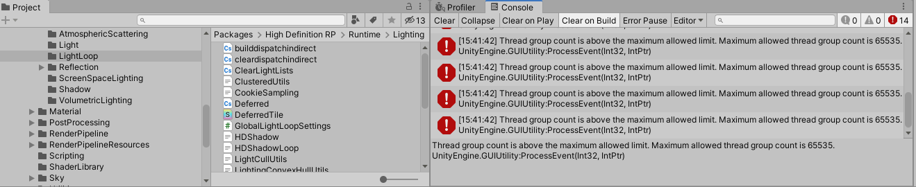
does anyone know a way to overcome the thread group limit for compute shaders? Or is that a hard limit?
I was asking a while ago about some trouble I was having reading Texture3D in a compute shader. I’ve now realised that my problem isn’t Texture3D, but rather Texture*D<float>. If I have some texture, 2D or 3D with a format of Alpha8, R8 (or as far as I can tell any other scalar format), then I only seem to get values of 0 from it.
I’ve now realised that if I use <float4>, then it works as intended. Texture3D has nothing to do with it.
Anyone out there had experience of being able to read scalar values from a texture in a compute shader?
Do switching from Built-In to HDRP break things, just like switching from Built-In to URP did to my project?
Or are Built-In Shaders compatible with HDRP?
Does anyone know if it is possible to add shaders to the Always Included Shaders list in the Graphics settings through an editor script?
Hi, I followed a tuturial on Toon outlines in Unity but I'm not shure why it doesn't work. I work in Unity 2020.3.30 urp, and followed everything from beginning to end (with the changes in the comments). But it's unclear to me why I get this result. Does anyone know what the problem might be? Would be a great help. 🙏
The thickness doesn't seem to change no matter how much I change the settings. And I don't see any difference on screen.


I don't know if I missed something.


Also looked at the material pass index but to no avail.
I'm trying to achieve a sort of "ambient occlusion" on my top down tilemap. The effect I'm looking for is like in Prison Architect, around every wall there's a bit of a darker area. I'm using a mesh for every wall tile that I set the vertex colors on to fade it out towards the end. Now I'm having issues where the meshes overlap. I've tried with writing to the stencil buffer, but I can't get it to work well even with aggressive alpha clipping (which would look bad anyway). Anyone have an idea for this which doesn't include picking a different mesh depending on neighbor tiles or combining the meshes into one?


Do switching from Built-In to HDRP break things, just like switching from Built-In to URP did to my project?
Or are Built-In Shaders compatible with HDRP?
I guess sure these limits would be at the graphics API / driver level rather than imposed at the Unity level. Do you have a particular reason for wanting to exceed them?
I've stumbled upon a repo which uses a high number of thread groups and somehow got it working but I'm gettinf the error of the limit being exceeded
Is it simulating hydraulic erosion by any chance? That seemed to be something that hit a few people here: https://forum.unity.com/threads/thread-group-count-is-above-the-maximum-allowed-limit-maximum-allowed-thread-group-count-is-65535.828420/
Unity Forum
I'm trying to port my game to HDRP. It is something like Motorm4x, and im trying to reach real HQ rendering. Hdrp's advantage is that metallic,...
Hey I've been trying to get a shadow caster working in my unlit shadow for a while now but I cant get it working. It says there 300 shadow casters currently in the scene however there is no visible shadows.
https://pastebin.com/w07zARtr
https://pastebin.com/gUYtBp8V
Pastebin
Pastebin.com is the number one paste tool since 2002. Pastebin is a website where you can store text online for a set period of time.
Pastebin
Pastebin.com is the number one paste tool since 2002. Pastebin is a website where you can store text online for a set period of time.
If so, this might help?

GitHub
Im getting this error when building the terrain "Thread group count is above the maximum allowed limit. Maximum allowed thread group count is 65535."
I'll check that one out thanks
hi everybody. I'm trying to apply a shader to pixelate a sprite after its been animated using a rig. Unfortunately, the shader seems to be applied before the deformation is calculated - as you can see in the image: the skin texture of the character is very pixelated, but the edges where the rig applies deformation are still smooth. What's the secret here?
The point of this shader is to undo the smoothing and stretching caused by the rig and return it back to 64x64. It's a 'Sprite Lit' URP shader

Hey there, in the last days I tried to create a custom shader graph to use as my skybox. When I apply the shader graph as the skybox it works just fine. The only problem is, that when I make unregular object in the skybox (not for example a gradient, but stars) they appear mirrored on the x-Axis. I supposed it is a problem with the method the texture is formed to the sphere of the skybox about I am not really sure. Can someone explain why the problem appears and how to solve it? Thanks
Do switching from Built-In to HDRP break things, just like switching from Built-In to URP did to my project?
Or are Built-In Shaders compatible with HDRP?
Hello. Is there any way I can modify this shader to display exact luminance at st position... e.g. instead of random shades, it displayed every 2nd square as black on the bottom row, the rest being white.


it is just the brick sub-graph in the shader graph samples that I want to modify
Can I have fine grained control over the cells
im new to learning how to write shaders and im having an issue with one of the passes where when i set the tag for lightmode to "ForwardAdd" it makes the object kind of transparent. any reasons why
actually ForwardBased not add

I have a camera problem that don't render into cubemap, where I can ask about it?
hi, so im new into unity, also new into graph shader, i just making bunch of simple testing. so my question, everytime i connect my other function shader to base color, why is my inspector not updating the information ? since my color shader are not connect anymore. or it just how graph shader works ?

Hey, so I'm wondering how I can get the local position in a surface shader accurately. This includes scale, rotation, and position. Right now I have the scale and position figured out, but when I rotate my object, the local position gets all whacked out. This forum post was the only thing I found, and it was slightly unclear. Has anybody dealt with this before? https://answers.unity.com/questions/561900/get-local-position-in-surface-shader.html
Unity is the ultimate game development platform. Use Unity to build high-quality 3D and 2D games, deploy them across mobile, desktop, VR/AR, consoles or the Web, and connect with loyal and enthusiastic players and customers.
It's nearly impossible to see your text, so I can't really tell what you're doing.
It's pretty obvious to tell though that because your colors aren't connected anywhere to your output, they're not going to do anything.
ah pardon, here's more higher reso screenshoot

wait, wrong config, wait a sec
ah sorry, thats not what i mean, i know i'm not connect the colors to block fragment, but my real question is, when i tried to looks on exposed properties (inspector) my exposed properties shown all of it.
Wdym it shows all of it? all of what?
i mean, if i dont connect it to block nodes, it shouldnt show to exposed properties right ?

No, the exposed properties are the properties you choose to show up in the inspector
If you don't want a value to show up in the inspector, don't expose it
wait, so thats mean, properties always shown no matter if its being used or not ?
Yep
ah okay", so i had to uncheck exposed later if i got final version of my shader ? is that right ?
i mean, on unreal i dont had to check or uncheck the "exposed" tick button if i dont connect the shader to block nodes output
okay", its clear for me. thank you for answer that
np
Hey there, not sure where to go for this and this is my best guess. Could anyone please help on how I could get a GIF as a material into unity that I can place on objects?
Unity doesn't import GIF files natively, either use a plugin to import you gif, or convert it to a format that Unity can import like a video or a flipbook texture
Hi, im following somebody tutorial on internet, and currently he using node called swizzle, my question is, how to only get 1 or 2 output from swizzle, node, what does it means green out, blue out, red out, etc ? i'm aware iam using old version of shader graph, but is it possible to get the same result like the newest version of swizzle nodes ?


which one is the new one? id assume that if you actually use a vector4 as input in the second one it would look similar to the first one
as for what the terms mean, swizzle reorders the vector so you can say the red output gives what originally comes in from the blue input
basically the first pic says: create a color that uses the red input value for each output channel but green stays green
the bottom one is the new one version, he shown using swizzle with 2 output from 4 vector. im trying to reimplement from his UDN method for blending normals
okay, but did blue and alpha output still had a value ?
they have the value of whatever comes in as red
do you have a screenshot of the 4 in -> 2 out? doesnt really make sense and the docs also dont show such an option
like if (1,2,3,4) comes in, the output in that example would be (1,2,1,1)
so this is comes from Ben cloward youtube channel, he did sample normal texture, then connect to swizzle node (new version, cause he did mention he using 2021 unity shader graph version)

okay, i get it now, then it still come out as value on output, meanwhile i only need two output on swizzle node, is that possible to do on my current version of shader graph ?
oh yeah i was on some older docs page, the newer one shows the mask
i think you could do it with a split connectoed to a vec2 or in case of the z output just use the z directly
he doesnt seem to use it to reorder but just to "filter" it out
yeah, it seems more like it, i want to use split nodes earlier, but im afraid the logic behind the nodes is different.
shouldnt be, what you put in the mask determines the output, mask length = output length and you can use x,y,z,w in any order to determine which input value should be used for that ouput
got it. btw just curious, if i want to mimic the swizzle nodes, does this screenshoot above work the same way as new swizzle nodes ?

i mean if someday i want to swap the orders of input to output and still only need two output using my current shader graph version
Use a vertex function, pass the object position in the v2f. It is the unmodified "local" (object) position without rotation and scale applied. (save it before calling a matrix conversion like ObjectToClip).
The position will be interpolated across the triangle.
Pixelating the texture itself independent of deformation is tricky because the outline of the mesh deforms as well
It would be best to upscale the whole rendered image in post if that's an option
hey, thanks for the reply. If you say upscale, do you mean downscale here, to "pixelate" the entire screen? I would like to avoid it because I might need to limit the pixelation to certain parts of the individual sprites (the edges for example) so as to preserve facial details. Not to mention this would also pixelate any shading etc. and not allow any objects I might want at a higher resolution. Isn't there a way to apply a shader just to the character after the deformation?
I do mean upscaling (though that often can involve downscaling first) to pixelate the whole screen
It is possible to pixelate the character's texture in screen space, but if you draw that texture on the mesh you'll still have a problem with the silhouette of the mesh which isn't pixelated as it's made of polygons, not pixels
Another option that comes to mind is to render to render target textures which aren't limited to the mesh outlines, whether you render the character or multiple parts of the scene onto that render target to get varying resolutions of pixel filters at once on screen
I can't think of a way to "extend" the mesh outline to allow the pixels go outside that border while keeping UV maps intact somehow
Would the render target approach get around the issue with the outlines? I would imagine this would involve the finished rendered image, only separated onto layers that are then composited to make up the finished screen? If so, this sounds like what I need
Yes, basically you would make a new quad on top of the enemy and render an image of the enemy onto that quad which is then pixelated (or rendered with low resolution)
The quad can be the size of the enemy, or encompass all enemies as a "layer"
Every rendertarget needs a camera for rendering it so it's not totally cheap
I think combining all the characters that should have pixelation on one render target should work fine. This sounds very promising, thank you 🙂 you wouldn't happen to know of an example where I could look at something similar being done? I'm honestly a bit out of my depth here
actually, I might need different render targets per character for purposes of proper occlusion I think. Either way, it's worth a shot
I don't have any specifically fitting guides at hand but you can find a variety of them by searching "unity rendertexture"
Also, if the rendertexture needs to have transparency you might need some solution specifically for that
I'll see what I can come up with, thank you very much!
Does switching from Built-In to HDRP break things, just like switching from Built-In to URP does?
Or are Built-In Shaders compatible with HDRP?
Hi, I'm working on a VR (single pass instanced) game and I have some matrices being set with C# and it looks different in each eye.
Are there any shader built-in equivalents to these two "functions" that internally use the eye index for stereo rendering?
var viewFromScreen = GL.GetGPUProjectionMatrix(camera.projectionMatrix, true).inverse;
viewFromScreen[1, 1] *= -1;
material.SetMatrix("_ViewFromScreen", viewFromScreen);
material.SetMatrix("_WorldFromView", camera.cameraToWorldMatrix);
I tried using UNITY_MATRIX_P and UNITY_MATRIX_I_V but either I used it badly or it's not what I want.
This is how they're used in the shader
float4 viewPos = mul(_ViewFromScreen, float4(input.texcoord * 2 - 1, depth, 1));
viewPos /= viewPos.w;
float3 wpos = mul(_WorldFromView, viewPos).xyz;
It breaks things but when you go to Window > Rendering > HDRP Wizard it has these buttons to help you convert stuff.

Thanks!
hello, i'm under the water..
i did a custom toon shader, but currently, my shadows are not cast
i use a lit one to have the basic shadow, get a main light function to the the main light, then i use a diffuse (ndotl) that i input in a additional light fonction that also do a diffuse on the additional after that i add the main diffuse to the result and input it in a light ramp and finally put in emission node of the fragment shader
i can't find how do have my shader with point/spots lights..
like that i do not have a shadow for the red spot

how would i do this in URP with our shadergraph material?

ok found it the setting is now called "Render Face"
howx can i get shadows for additionals lights ?
these icons should all be in circles. it worked until I switched to using a texture-atlas. this has messed up the uv coordinates (makes sense). how do I get the coordinates from 0-1 again for the texture I am showing?

o.uv = TRANSFORM_TEX(v.uv, _MainTex);
o.coord = v.uv; //how to transform this?
Anyone knows how to use RenderTexture in compute shader with RenderTextureFormat.R8 format which is supposed to be 8 bit integer. Using Texture2D<float> I managed to get it working but Texture2D<int> always gave me blank texture. I used int buffer earlier so I think it’s not about my compute shader returning wrong values
I had issues with some of the texture formats, maybe not supported
@rancid silo Freya holmer does great tutorials and explanation
anyone to help me please ? 🥺
SystemInfo.SupportsRenderTextureFormat told it should be supported. Is that what you mean?
what renderpipline do you use?
in hdrp you need to enable the shadows for each additional light on the light itself
urp; every light has shadow enalble, just my additional light handling do cast shadow and i can't find how to do that; my code is currently that :
void AddAdditionalLightsSharp_float(float Smoothness, float3 WorldPosition, float3 WorldNormal, float3 WorldView,
    float MainDiffuse, float MainSpecular, float3 MainColor,
    //returns
    out float Diffuse, out float Specular, out float3 Color) {

    float mainIntensity = GetLightIntensity(MainColor);
    Diffuse = 0; MainDiffuse;
    Specular = MainSpecular;
    Color = MainColor * (MainDiffuse + MainSpecular);

#if defined(SHADERGRAPH_PREVIEW)
#else
    float highestDiffuse = Diffuse;

    int pixelLightCount = GetAdditionalLightsCount();

    //Light mainLight = GetMainLight(shadowCoord);


    for (int i = 0; i < pixelLightCount; ++i) {
        Light light = GetAdditionalLight(i, WorldPosition);
        half thisDiffuse = light.distanceAttenuation * light.shadowAttenuation * GetLightIntensity(light.color) * saturate(dot(WorldNormal, light.direction));


        thisDiffuse = light.distanceAttenuation * light.shadowAttenuation * saturate(dot(WorldNormal, light.direction));

        thisDiffuse = light.distanceAttenuation * light.shadowAttenuation * GetLightIntensity(light.color) * saturate(dot(WorldNormal, light.direction));


        half thisSpecular = LightingSpecular(thisDiffuse, light.direction, WorldNormal, WorldView, 1, Smoothness);

        Diffuse = MainDiffuse;
        Specular += min(MainSpecular, thisSpecular);

        if (thisDiffuse > highestDiffuse) {
            highestDiffuse = thisDiffuse;
            Color = light.color;
        }
    }

    Diffuse += MainDiffuse;

#endif
}``` but that's not the solutioni saw that https://docs.unity3d.com/2022.1/Documentation/Manual/SL-VertexFragmentShaderExamples.html but i don't know if i can put it in my function somewhere

or if i should tranform my entire shadergraph into a full code shader
the way that unity handels additional shadows in URP shaders is kind of wired so not super straigt forward how to integrate it
maybe you know wher ei can find doc about the shader lights functions ?
i found this article about LWRP (the old name for URP) about custom lighting and shadows in shadergrpah
https://blog.unity.com/technology/custom-lighting-in-shader-graph-expanding-your-graphs-in-2019

the example code of "AdditionalLights_hlaf" looks like somting like it
@latent thistle
If you're in v10+ you should add a third param to your GetAdditionalLight function. It's required to calculate the shadowAttenuation value. Technically it's for supporting the baked ShadowMask mode but if that's not important can just use a value of 1. e.g. GetAdditionalLight(i, WorldPosition, half4(1,1,1,1));
There's also _ADDITIONAL_LIGHTS and _ADDITIONAL_LIGHT_SHADOWS keywords which should be created in the Blackboard if using an Unlit Graph.
https://github.com/Cyanilux/URP_ShaderGraphCustomLighting
oh
you are here
you have to know that i love you so much guy
i read a lot on your blog
he has a blog 🙂 never knew thanks 🙂
yeah, that's i try on my code that i put here
yeah, is it amazing things
he his here 😂

daniel ilet too is strong for tutorial
ned makes games too and also roystan
also, i'm using a lit shader to have the basic shadows
okey, i'm totaly retarded, i was editing the wrong function since a moment... si my last code was right 😂
thank you all

we've all been there...
it's close to midnight, maybe a clue that say i need to sleep
how make shader?
look online. If you need help then ask here
Hey, I'm really confused as to why my texture isn't being applied to my custom mesh. Everything's working fine on the sphere, but as far as the custom mesh, only one color of the texture is ever displayed. (It may be hard to see in my picture, but the normal sphere is doing everything perfectly) As far as I know I'm doing everything properly. Here's the shader code. Literally all it's doing right now is sampling the texture and displaying it as the albedo, yet it's not working. It's just a standard surface shader.
EDIT: Yes, I do know that the material is also being updated on the custom mesh. changes I do to one affects both.
Another edit: I'm beginning to think it's because I'm not setting the UV's when I generate the mesh. I don't know how to do that so currently I'm looking into that.
aaaand another edit: After a lot of research I got something working. It's not perfect, and there's a lot of distortion, but at least I'm getting a texture applied to the custom mesh. The problem was that I wasn't setting the uv's. Now I just have to figure out how to get good uv's.
        fixed4 _SteepColor;
        float _Sharpness;
        float _ColorChange;
        half _Glossiness;
        half _Metallic;
        fixed4 _Color;
        sampler2D _StoneTex;
        sampler2D _GrassTex;

        struct Input
        {
            float3 worldPos;
            float2 uv_GrassTex;
            float2 uv_StoneTex;
        };


        void surf (Input IN, inout SurfaceOutputStandard o)
        {
            fixed4 grass = tex2D(_GrassTex, IN.uv_GrassTex);
            fixed4 stone = tex2D(_StoneTex, IN.uv_StoneTex);

            o.Albedo = grass.rgb;
            o.Metallic = _Metallic;
            o.Smoothness = _Glossiness;
            // o.Alpha = c.a;
        }```
Good night and sorry to disturb but who can help me I really appreciate it I would like to know a way to create a shader or a material that when looked at from behind it becomes invisible and when I look from the front I can see the object
Something like this @normal rose ? https://www.youtube.com/watch?v=S5gdvibmsV0
A tutorial on the see-through-objects effect used in my game Treasured. It uses Unity, URP and Shader Graph.
Note: this was created with Unity 2019. It might not work for newer versions since they have not been tested.
Social Media:
Twitter: https://twitter.com/HuntersonStudio
Twitter: https://twitter.com/Casualdutchman
Twitch: https://www.twi...
Not exactly sure off top how you could specify whether looking at front or back though of the object just yet...
from what i saw this will help me in my project but it is not what i was looking for can i send pictures to try to explain it better?
the object from the front is seen like this

when the player is behind it has to disappear

😢
Sorry mate, I don't know much about shaders 😦
According to this post https://answers.unity.com/questions/1842555/how-do-int-textures-work-in-computeshaders.html writing to Texture2D<int> isn't possible for some reason. Reading from int texture seems possible so I think i'm going to use Texture2D<float> in the compute shader and Texture2D<int> in the fragment shader drawing the render texture assuming there's no problem in changing the format of texture between different shaders. Atleast it seems to work and doesn't give me any errors.
Hi i don't know what is this on the shader graph. is there someone to helps me ?

I haven't actually used shader graph, but I imagine it's just used for visual routing in the graph view itself rather than actually having any effect.
so a simple line will do the same ?
Yeah I imagine it's just for cable management, hopefully if I'm wrong someone'll correct me.
Okay thanks you 🙂
nah xinaes you are right its just to make the graph more clean, it has no functionality otherwise
besides changing the path of the connection you can also use it to make it look better if you want to connect the same output to multiple inputs
thanks for the answer 🙂
I wonder if you have any insight for me... I am singularly failing to ever read any non-0 value from a Texture2D<float> in a compute shader. I haven't tried <float2>, but <float4> works ok. (I also just tried <int> on my mac, which hits runtime assertions along the lines that TextureFormat.R8 isn't compatible with <int>, I imagine this would be similar on other platforms - expecting R8 to be an unsigned normalised byte).
But really, this has been driving me somewhat nuts and if you can just confirm that you are actually even able to read scalar <float> (or any other scalar number type, but preferably from an 8bit source) from a texture in a compute shader that's some new information for me. It also might be possible that, like me long ago, you have some code that seems to work and doesn't give any errors, but that when you get down to the details of trying to get any useful results from it you eventually hit the same issue.
This is how I initialize the rendertexture:```cs
texture = new RenderTexture(resolution, resolution, 1, RenderTextureFormat.R8);
texture.stencilFormat = GraphicsFormat.None;
texture.depthStencilFormat = GraphicsFormat.None;
texture.enableRandomWrite = true;
and this is the compute shader:```cs
#pragma kernel Randomize
RWTexture2D<float> Result;
int Resolution;
float Coverage;
float Time;

[numthreads(8, 8,1)]
void Randomize (uint3 id : SV_DispatchThreadID)
{
    float2 p = float2(id.x, id.y + Time);
    float3 p3  = frac(float3(p.xyx) * .1031);
        p3 += dot(p3, p3.yzx + 33.33);
    Result[id.xy] = step(frac((p3.x + p3.y) * p3.z), Coverage);
}
Also reading from Result in compute shader doesn't seem to be a problem. Currently I'm actually using the same texture render texture (declared as Texture2D<int> Result) in fragment shader without problems.
Thanks. I'm not actually using RenderTexture (and not trying to write), so given that's a variation I haven't tried it may be worth giving it a go. Ideally I'd rather not to have to change other code to make a RenderTexture, but it might at least help to put my mind at rest. I think perhaps there's a bug in Unity.
I have just been testing with a fragment shader, where I was able to read from my Texture2D<float> and also write to a RWStructuredBuffer, so there's a chance that as a hack I end up using a fragment shader to do work that should logically be in compute shader. (edit: I may be less inclined to use this workaround since Unity is spewing out lots of spurious warnings about missing bindings).
normaly when mapping a texture uv coordinates go from 0-1, when a texture atlas is used this changes. is there a way to get the 0-1 range for that quad again in shader code?
is there any equivalent panner nodes on unity ? i found it on amplify shader, but cant find it on shader graph itself
"Panner"? Tiling and Offset, perhaps
but how, do i move the speed, by the location, i mean on panner by amplify shader itself, there's speed that give us to move those coordinates by the time i set. how do i reach that using tiling and offset ?

Time node for time, feed that to multiply/divide to control the speed, that to Vector2 node if you want it per-axis, that to offset input of Tiling and Offset
like this setup right ? but still it not panning by vector value i input on X

did i do it wrong ?
The Tiling And Offset would go into the UV input on the sample
ah finally, okay, it moving on the direction i expect based my vector value, thank you for the help
scalar value in compute shader
Am I misunderstanding something or are ComputeShader.SetBuffer and ComputeShader.SetTexture almost 0 cost operations? Do they really move some data or do they just give the reference to buffer or texture as I think they do?
They won't be moving substantial data and you probably shouldn't worry about the cost, but any call to graphics API has some overhead, including resource binding.
thanks 🙌
Hi, I work in Unity 2020.3.30 urp, and followed this tutorial from beginning to end (with the changes in the comments). But the thickness doesn't seem to change no matter how much I change any settings. I checked debug mode and all multiple times, but don't see any difference in thickness. I'm not certain if have to make any changes for Unity 2020.3.30. Does anyone know what could be wrong? Would be a great help. 🙏


Did you unwrap UVs for the custom mesh? if not it will pick only first pixel in the texture for each pixel on the screen.
small tool question about shader; i'm using visual studio with reshaper but there is no autocompletion and autoindent is totally fuc***
Do anyone has a fix to have this feature that work properly ?
Good afternoon everyone!
I am using custom shaders from the Mix and Jam team on Youtube to make a painting effect, similar to that from Splatoon.
All I want to achieve is the painting effect using mouse.
I have narrowed down the problem to the shader mask "not updating" or rendering in both the camera view / Editor view, yet when I select the object that I am painting on with the custom shader - I can see that the mask is being updated in the editor during run time, as I send a ray to the surface of the object.
I am a beginner and do not know how to debug to see where I could have gone wrong in the render process - whether it is coordinates, perhaps the scaling of the mask or if the texture position(world space) to screen space transfer is haywire because my camera moves or project settings to adjust for the custom shaders.
I have made a new clean project and reintroduced the scripts and the only minor changes to the original code have been changing the input system, other than that - only 1 compile error that relates to the scripted assignment of a shader (Which happens on the original project and works still)
Been stuck on this for the last couple of days and could really use the help. Screenshots below.
Apologies for the essay.


Yes, that's what all the edits were about. However, the problem is that because it's procedurally generated, I can't really just unwrap them. I'm looking into triplanar mapping to properly get textures mapped.
Ou sorry, im sleepy today. Uhm yes, well there are two of them, first it seems like you have quad cube and spherize it, so you can unwrap the quad before spherize happens. But this will have seams between quad sides. Triplanar is easier, but a bit more heavier. Normals can be a bit harder to do right.
yeah, it's a quadcube. I might just try both to see what works the best.
So, I did the UV mapping on the planes beforehand, and that gave me no seams. Which was a little strange. Not entirely sure why, but as long as it works I guess
Hi guys is there anybody know what causing this shader error? i'm only getting this on ios/Metal. Using Birp
mismatching vertex shader output type(s) or not written by vertex shader
Is there an easy and fast way to get the scale of a mesh out of a localToWorld unity matrix in a compute shader, or should I send it in seperately?
but can I access it quickly in a compute shader from the matrix itself or would it be better to just send it as data
oh sorry i forgot we're in shaders
yeah it can be extracted from the matrix in the same way, jsut don't remember if there's a HLSL function for it or not
thx!
ive been trying this for ages and im so frustrated because it wont work
ive tried to follow this tutorial https://youtu.be/MPVgJqhsaWU

Neon, glow, bloom. Call it what you will, this video helps you set it up for Line Renderer with Universal Renderer Pipeline and its post processing.
0:00 URP Setup
0:33 Post Processing Setup
1:03 Material Setup
and it just doesnt work for some reason
everything he does, i do
but then when i modify the hdr intensity it only changes color
can anyone help me figure out what im doing wrong
bloom materials in general just dont work for me
Hello, has anything changed with shader graph in 2021 because i have a texture input and color input that should be exposed in the inspector of my material using the shader but they are not

exposed is on in both
oh never mind i did not save yet so it did not yet get applied
ignore my question
It seems the shader graph isn’t saved


in 2021.19 its closed to the bottom, no longer in shader

hey all, i was hoping someone could help a newbie. i am trying to recreate the 'overlay' blending mode for some sun ray sprites in my project. i have downloaded this, installed the package. https://github.com/zigurous/unity-blend-shaders/packages/656602
but i how do i access these options? thank you in advance

GitHub
🔲🔳 Shaders for blending objects in Unity (based on Photoshop's blend modes). - Package com.zigurous.shaders.blending · zigurous/unity-blend-shaders
the sprite im trying to use the shader on if it helps
You'd have to use that in the standard (built in) pipeline, not URP or HDRP.
There's a shader for each type of blend. You'd put that shader on a material that you create. Then assign that material to an object.
Here's a list of the shaders in that package:
https://github.com/zigurous/unity-blend-shaders/tree/main/Shaders
GitHub
🔲🔳 Shaders for blending objects in Unity (based on Photoshop's blend modes). - unity-blend-shaders/Shaders at main · zigurous/unity-blend-shaders
@meager pelican thanks so much for your response. i made the material and attached the shader. apologies in advance if this is a stupid question, but do you possibly know why it is coming out this colour? thanks again

That's an error color. What pipeline are you using? (if you're in URP or HDRP, that won't work for those shaders. Or there's another error of some kind, check the console log, or click on the shader in the inspector and check for errors showing on the inspector panel).
i just imported the shaders, made a material and attached the overlay shader. i think i need to go back and watch some more tutorials, as i actually have no clue about pipelines😅
Is there an easy way to turn a standard shader into a URP shader?
Shaders are pretty much magic to me.
you should be able to click on that and from the dropdown menu change it to a URP Lit Shader
as long as you have URP installed and everything

yeah, I'm using ECS and finding it through code, is it still possible to do that? I seem to be getting a an error regarding a "Redefinition" inside the shader, but I can't figure out the problem since it's not misspelled...maybe I should just link it and let you guys see
Hmmm... your problem might be a bit over my head then.
but I'm pretty sure that's possible
you have a bunch of materials you need to change over to URP?
Doesn't Unity have a built in thing for that?
https://pastebin.com/nN74ibJm
This is the code for the shader and it's complaining about _MainTex_UV at row 46 for some reason....
I suspected it might be because this shader might be made for the basic rendering pipeline and not URP
Pastebin
Pastebin.com is the number one paste tool since 2002. Pastebin is a website where you can store text online for a set period of time.
It's not the material I wish to change, it's the shader itself and the code inside the shader that potentially needs changing to work with URP I believe.
I see.
also you've got enable GPU Instancing checked on the material right?
What's the error it's throwing at line 46?
im a bit out of my depth, but I've seen others code that used uv_MainTex instead of _MainTex_UV
and also im not sure if UVs should be fixed4 or fixed2. 2 seems logical to me, but idk what im talking about.
good luck! :) @ me if you solve it
Why i cant see a Stylized Grass material?
anyone has idea to do a radial distortion effect for post process ?
To have a speed effect for a space shuttle
Hi, my shaders aren't working in builds. On google they said I should add the shaders to the always included shaders list, but this didn't solve it and I can't find another solution
are you using shaders that do not support your target platform?
No they support my target platform
hey guys is there a way to make a material that cut trough other objects, like a window, its see trough and lets say i apply it to a box and whats inside in the box is invisible but i can see trough the box?
aleksih.
How is it possible my ComputeBuffer doesn't get cleared even though I call buffer.Release() on the end of run and next time create new buffer? The newly created buffer seems to memorize the values from the last run buffer. Things gets even weirder when I try to create different sized buffers: the values of new buffer seems to get copied from the last time the same sized buffer was used.
DId anyone knows a good - free -, ANIMATED Billbord Shader (Advertisements , not Grass or Trees), for Built In RP ? ( no Shader Graphs plz. Shader code).
or a Place i can get a source ?
Hello, i hope this is the right place to ask, i am a student and just starting to use unity, my team agreed on to implement a celShader, and i found this youtube video: https://www.youtube.com/watch?v=lUmRJRrZfGc&t
I copied all the code from his github, and everything works fine in his githb project, however, when i try to implement everything in my current project, i cant get it to work, i changed the render pipeline in the project settings, and when creating a new material i select the shader file (he used) but all my materials still end up pink, i really hope someone can help me with this, i cant continue working until everything is fixed

Tons of games use a stylised cel-shading art style to help them stand out graphically, including hits like Zelda: Breath of the Wild, Persona 5 and Okami. In this tutorial, we'll unlock the secrets of cel-shading in Shader Graph by using our own custom lighting and end up with an effect that supports multiple lights!
👇 Download the ...
If all materials are pink the render pipeline is probably not set up correctly
hi, im new to shaders. i was wondering if anyone could advise me some good learning materials (websites, videos, books) for 2d shaders in unity. I researched this on my own, but in the plethora of links, i cant find a decent place for a beginner like me
and many of these articles are complicated. I thought shader programming was easy, but its harder than ai
for some reason closing and opening fixed my problem, works now
Hi, I upgraded my unity from 2020.3 to 2021.2.7 and upgraded all the things in Renderer Pipeline Converter, yet all my materials are all really buggy. How could I fix this?

What makes you think that buffer.Release() clears the buffer? IDK why it would, just extra overhead.
Clear the buffer yourself, either by setting values in C# or using something like a compute kernel.
Like playing a movie, or using a flip-book?
how can i use unity surface shader with custom vertex/geometry shaders?
@inner dune It's pretty simple. You need to add vertex:vert in the pragma, and then you can add your vertex shader
....

void vert (inout appdata_full v)
{
 ....
}```Hey folks, I'm new to shaders and working on a school assignment. I'm running into an issue I don't quite understand. I'm trying to add a transparency value to a shader, but I'm getting this weird clipping effect with objects behind the shaded object. Anyone able to point me in the right direction to understanding why any alpha is clipping part of my tree away?


Was just a tags issue:
Tags { "Queue"="Transparent" "RenderType"="Transparent" } fixed it
This has been frustrating me for a bit. I'm working on a water shader, and I've been doing pretty well so far. But the scrolling normal maps are just driving me crazy. I only want the normal maps to break up the lighting, but I have no idea how to do that. As you can see, when when I have the normal map, it affects everything (like normal maps should, of course). Here's the code for the normal maps. It's very simple.
            fixed3 normal1 = UnpackNormal(tex2D(_Water1, IN.uv_Water1 + (_Time[0] * _ScrollSpeed2.xy)));
            fixed3 normal2 = UnpackNormal(tex2D(_Water2, IN.uv_Water2 + (_Time[0] * _ScrollSpeed1.xy)));
            fixed3 totalWaterNormal = normalize(normal1 + normal2);
            o.Normal = totalWaterNormal;```

like playing a movie will be nice.
Something what moves UV Maps.
I’ll make new kernel to clear it. Atleast I imagined creating new buffer using the ComputeBuffer constructor would give me clear buffer but it doesn't.
https://thebookofshaders.com is nice. Not Unity specific, but fairly transferrable.

The Book of Shaders
Gentle step-by-step guide through the abstract and complex universe of Fragment Shaders.
I don't see the issue, you have the normal that affects the water surface, isn't this what you want ?
Anyone knows a solution to this?
I'm new to Unity and have some trouble with shading. I would like to put the position to world instead of view, but when I put it on world I get a lot of stretching. Does anyone know a good method or tutorial that can help me with this?

on view

on world


What is your goal?
If I had to guess you're looking for the Triplanar node
Guys anyhelp on how to make a shadergraph, like where we can apply a papery overlay texture on top of a base texture and then scroll it a bit with time, like a paper doodle effect on a 2d sprite
how can I get a new instance of a custom compute shader?
So I have a compute shader that takes in positions and alters them
I want 2 different objects to both use 2 different instances of this shader (since they will be giving in different positions)
Right now, I have to drag an drop the shader in a serialised field since idk how else to tell unity to use it, and so the 2 objects are pointing to the same shader and it's overwriting the values
Hey is there a way to make a material that is see trough and if its intercepts with some other object it "cuts trough it", like a window
You probably just need to make sure that you change any uniform bindings before each Dispatch() call.
An Alternative to having it in a serialised field would be to have it in a resources folder and use Resources.Load, but I’m not sure if that would mean that you ended up with isolated instances or not.
apparently doing computeShader = Instantiate(computeShader) should work but it's not, will keep looking tho
actually I think I found the problem, it's because of the material now, the cshader is fine but each instance points to the same material and that's causing problems
anyone know why im not seeing Unlit Graph as an option here?

I'm pretty sure you can set the shader to unlit in the shader graph itself.
Yes, but as I was stating in the description, I only want the normal map to break up the sun's light. It looks very ugly in the places that aren't directly affected by the sun. The picture I sent probably doesn't do it justice
Looks like you're using surface shaders ?
If so, and without doing your own custom lighting to fake this, it's a totally expected result from normal mapping.
Maybe a solution could be to just reduce the normals intensity, as they appear to be very strong.
An easy way to do it is to use UnpackNormalWithScale(fixed4 packednormal, float scale) instead of the UnpackNormal(fixed4 packednormal) you currently have.
Yes. that's correct i'm using a surface shader. Again, as I stated I was aware that this was the expected result. Thanks for that function though, that's actually pretty useful. So what you're saying is that there's not really a way to do this in a surface shader without custom lighting?
Yes. You said you wanted to only "break the sun light", if I phrase it in my terms you "want to break the sun's specular reflection" (the bright spot on the water surface). And this is only possible by doing custom lighting, as you'll be able to de-correlate the lighting from the surface information.
Okay thanks, I'll look into that function. Either that or I'll just move my entire surf shader to an unlit shader, although that would be a bit of a pain, as I'd have to do all the lighting myself. I appreaciate the help!
When i add URP pipeline in my project , even cubes became invisible, why?
Alright, well I did the UnpackScaleNormal with some depth and stuff involved and it honestly worked really well. Thanks a lot for that
how to repeat the Hilbert curve numers after N frames?
How do I get the distance from the nearest vertex in shader graph?
in the fragment stage?
Well I'm going to plug the values into the fragment
Not sure really 😅
Yeah I'm not even sure it's possible.
The catlike coding website is really good for shaders, albeit a bit complicated. Shaders in general are not the easiest thing in the world to learn. The absolute best way to get better at them is to just do it (sounds stupid I know). But just experiment around with the shaders, look at other people's code, follow shader graph tutorials and convert them into shader code, etc. You'll have to learn the basics first, but once you get there it's pretty awesome.
For the Texture2D sample node in shadergraph, what do the actual different modes do? I see white, black, bump, grey. The documentation is really vague here, but seems to suggest the bump mode will do some normal map decompression (so assumes a certain texture format). What about the others? Are these default values?
(It looks like they are from very rough testing, but there's no mention in docs)
The texture modes determine the default value when a texture is not assigned.
It's the same as the string at the end of the property definition in ShaderLab. e.g. _Name ("DisplayName", 2D) = "white" {}.
Put the following values in the default value string to use one of Unity’s built-in textures: “white” (RGBA: 1,1,1,1), “black” (RGBA: 0,0,0,1), “gray” (RGBA: 0.5,0.5,0.5,1), “bump” (RGBA: 0.5,0.5,1,0.5) or “red” (RGBA: 1,0,0,1).
(From https://docs.unity3d.com/Manual/SL-Properties.html)
Shader Graph apparently doesn't give access to the "red" option.
cheers cyan!
So I just learned how to use shaders, I'm trying to create an outline shader that I can add to any game object to give it an outline (My games a 2d sidescroller btw) I originally tried to create 4 copies of the original image, make them black, and offset them, but that didn't give me the result I wanted, so now I'm trying to have one image that gets scaled with a slider to create the outline, my problem is I don't know how to adjust the size of it in a shader (I only started using shaders yesterday so im still quite new). Some help would be much appreciated
Hi everyone, is it possible to rewrite the URP lit shader as a shader graph? Or at large parts of it (I understand that looping over additional lights is tricky)? Does anyone have a resource for doing something like this, or has it been done already? I'd like to be able to essentially recreate parts of the URP lit shader, but in an unlit graph, so I have more control over parts of it.
Yes that's the option I see mostly used. Just not sure what's best tutorial for urp.
The tutorials are mostly about creating your own triplanar function before there was a node for it
Now all you need to do is plug your texture into it and set the blend value
so... Unity broke built-in SG target on 2021.3? 🤔

actually.. it works if I also import URP package (just having SG and core wasn't enough)

trying to make an outline shader
howevedr
i need to be able to stop adjacent sprites from having an influence on the current one somehow
and also render the outlines outside the bounds
eg. below the rocks
maybe a second pass but i have no clue if thats possible that way
Hi. So as I understand GPU instancing doesn't work with additive lights in ForwarsAdd pass, is there a way to fix it?
It just says that draw call can't be instanced because an object is affected by multiple lights
I use built-in render pipeline
ok i got it working with multiple passes but because im using _MainTex_TexelSize sometimes its 1 pixel, sometimes 2

is there some easy way to be able to say exactly 1 pixel
hard to tell without knowing more about implementation of that outline effect but usually partial derivatives are used when we want to have pixel width lines and things like that
right now im just using 4 extra passes, that offset the image TL TR BL BR by a constant (0.04) and setting pixels with a > 0 to black
what are you offsetting atm? the mesh itself? uvs?
yeah the mesh itself as to not get outlines from adjacent sprites in the same texture
i just started learning shaders from brackeys cartoon water tutorial and I installed the universal render pipeline package but his looks a lot diff then mine (i cant figure out where to connect things)


although i can do it with image too, this was what i tried before just made a script that gives the shader information about the sprite boundaries
I'm not sure what you mean by that but that makes things a lot harder because you can't use partial derivatives on vertex shader
for example, in a spritesheet like this if i just offset the uvs then the red staff would have a bit of the green and blue staff's outlines

so youd see these black lines

but i do have a workaround for tha
but you can use them with uvs then?
if you do that in fragment shader, yes
you could take a look at this if you wan to learn more about partial derivatives https://www.ronja-tutorials.com/post/046-fwidth/
ahh ok i see
partial derivative sounds a lot more complicated than it is lol
was expecting calculus
ok i forgot that offseting uvs also has this problem, that now i cant draw outside the bounds


Different techniques for rendering outline effects.
this seems its for 3d though?
yeah, that's a problem. as far as I know, there's no easy way to increase the size of sprite mesh. you could probably scale up the mesh in vertex shader and scale down the uvs so it would look the same but have more space on every side of the sprite. I haven't tried that myself but maybe wort a try
maybe
ok well turns out it scales by its pivot which is a problem if the pivot is on the bottom edge
I wanna try and attempt a thermal overlay - similar to those of thermal scopes in CoD
How would I achieve this? I'm thinking (though may well be wrong) that smoke could be placed on a smoke layer or render layer and then the opacity of the smoke could be adjusted or smoke inside the view could be ignored
I also want that cool visual effect via a render texture and im gonna try and work that out
How to solve pink water shaders?
maybe you have an error?
Oh np I sorted out the problem : D
I don't see why that would be a problem (I tried and it didn't change anything but I got some other problems with the shader approach) but I just found out that actually textures have this property to leave more space around the sprite. I think that should fix the problem without having to scale anything in the shader


have you tried increasing it and applying the changes? so that doesn't make the outlines work any better?
yea no change at all
only thing i have found is to leave a 1px gap around every sprite but thats rather impractical

oh wait, this is weird. it seems to kind of leave more space around the texture but it doesn't expand the mesh outside of the certain rectangle area
one solution is to put a world space canvas and an image and then use the outline but thats

well
using an image and a canvas
anyone with knowledge of how to use commandbuffers have some insight into this question?
now I get what you mean. if you know the pivot is always at certain position, you should be able to use some math to scale it around the center point
yea but the pivot is different for different sprites
some sprites have it at the center, some at the top, some at the bottom
i mean i got a crazy idea
probably not a good idea
but make all the spriterenderers run some method on a canvas to draw their sprite as an image
and update it every frame
could something like this work if you are suing sprites?
https://assetstore.unity.com/packages/vfx/shaders/2d-sprite-outline-109669

Add depth to your next project with 2D Sprite Outline from Hanna Fiani. Find this & more VFX Shaders on the Unity Asset Store.
ive looked at that a while ago and i cant remember what it was but it didnt work
ok yea it just doesnt work with spritesheets

really thats it? ooh wow thanks 👍 👍
@night isleYes, it is. Sorry. Some of those techniques may work in 2D space though either object or screen (alpha clipping in a sprite quad, which can be extruded in 2 directions instead of 3, still not ideal I suppose).
You MIGHT be tying yourself into knots. Why not draw the skybox at the far plane location? That's pretty much what skybox shaders do. You won't have an issue with transparent objects then.
Hey so im having a pretty big issue with a compute shader(and it being a black box is making this incredibly difficult)
Basically, I have one kernel that I believe stalls the program for a solid second(when I turn it off the stutters go away), but only once every like couple seconds(despite the fact that every frame it is fed different data, and it runs EVERY frame), with a very consistent time interval between the stutters, I believe its reading from out of bounds data(in previous instances it would display things that no longer physically existed)
Is there a way for me to profile this at all to see whats happening? Cant use unities profiler because the extent that it tells me is "There was a spike here, what caused it? compute shaders, which kernel? shrug you got 12 kernels, pick one"
and I cant really use nsight, because of the fact it only happens for one frame every 1-2 seconds
Any ideas for something I could do, or just trial and error it?
https://cdn.discordapp.com/attachments/905926809789562890/964991951139135618/ezgif.com-gif-maker_21.gif

ive sort of had success with something similar to most of the methods, just offset the mesh however i need it to be exactly x pixels on each side every time, and doing it this way creates inconsistencies
but using ddx or ddy is only possible in the fragment part of the shader
The only way I know of to do "real" code level debugging is with GPU vendor tools.
However, RenderDoc and Pix may help some, I don't recall the details off the top of my head. IIRC both capture frame detail and let you do analysis on it/them.
hrmmm
problem is getting the right frame, and last I checked they dont do compute
Dang
it seems to be good on the first run after a code recompile
but after the first going into and out of play mode it breaks
hrm shifted all my code into a fresh unity project and it works?
lol
wow
welcome to unity
Uhmmm....IIRC, you use a debug build with shader pragmas included for debugging. Not in engine. Otherwise you capture engine frames, not game frames.
might be! i'm not sure how to do go about doing that. do you mean ignoring the unity skybox and drawing it manually, before the opaque geometry is drawn, over the entire screen?
I have this blood splatter particle system that generates a random pattern based on noise, but every particle in the system has the exact same pattern, is there a way to change the offset of the noise when a particle is created?

You write your own skybox shader. Unity will call it at the right time, between the opaque and the transparent passes.
ah -- yeah we do have a custom skybox shader
the problem i'm running into is unity only draws the skybox on fragments where depth is max (afaict)
so if i alpha out or drop fragments in our post-processed texture containing the opaque objects, the clear color comes through behind it instead of the skybox
I have no idea what you're saying, sorry.
I mean, if a tree is at the midpoint between the skybox and the camera, it SHOULD block out the skybox. So the only place you want a skybox to show up is where you DON'T have geometry, which is why they draw it between opaque and transparent passes. This avoids drawing unnecessary pixels where the skybox is occluded, and is faster. Takes advantage of an early-z test in hardware, the fragment shader stage never even needs to be called for occluded pixels.
Oh, wait, you're "dropping out" opaque pixels?
You may need to...write depth in your post processing shader to a NEW depth buffer, either copying it from the old or dropping it out to the far-plane. Then you don't have to have some kind of other pass.
But IIRC, having a bunch of depth buffers is a PITA. And IDK if I can tell you how to do that. But you shouldn't have to save/restore type of logic, just replace type of logic. Maybe.
hmm okay, thanks!
Back to the original issue, in order to make it always one pixel width, you have to offset the outline by exactly the amount of one pixel on the screen. I think 2f * Camera.main.orthographicSize / Screen.height should give you (with multiple screens and cameras that may get messed up tho. Calculating that in shader using screenparams and orthoparams could be bit safer in that way but if you need to do that in every of those 4 passes, thats going to add bit of overhead. The amount of overhead is going to be very negligible anyways because the vertex count of those sprite meshes are very low) the amount of units (meters) one pixel on the screen covers. If you offset the outline by that amount (note that that’s the offset in world space. If you offset by that amount in local space, you will get varying results between objects) on every direction, you should in theory get one pixel width outline (in practise you may get some edge cases very rarely). You could use global shader properties to give that value for all the shaders at once. Using 4 extra passes just doesn’t sound the most efficient way but that’s most likely not going to going to be a big performance problem either. I think that’s pretty close to what the default UI outline effect does too (actually just read some posts about the UI outline being very slow on mobile platforms but those posts were years old so that’s most likely not the case anymore. You can always use profiler if you’re worried)
yea ive actually looked at the ui outlines code and im pretty sure its just duplicating verts and offsetting them sort of like i am
i havent actually thought of trying to get the exact pixel size somehow so ill definitely try that now
i have no clue how i havent thought of this
i literally played around with the _ScreenParams variable
That’s the way youd do that with partial derivatives too. Partial derivatives are just very useful for getting the amount to offset to get exactly one pixel width offset (using partial derivatives you can very easily get the amount of offset on local space for example)
i might just be overlooking something obvious but what


You’re not supposed to declare built-in shader variables like that. You can just use them in the code wihout declaring them in any way
oops
my ba
D
oh yes i think this works
ok its not quite right
its not 2f *
it seems to be around 0.25 but not 0.25
I think you’re now trying to offset them in local space

You can first transform the local space position into world space, offset that value and then transform it from world to clip pos
You can use unity_ObjectToWorld and UNITY_MATRIX_VP matrices for those transformations
still, its sometimes a bit too small


Actually it seems unity_OrthoParams.x is already 2 times the orthosize so you don’t need the 2 there
but then theres even more missing edges
perhaps its just a matter of getting it as close as possible
2.85 seems to be it
tried changing resolution and aspect ratios etc and 2.85 * (unity_OrthoParams.x / _ScreenParams.x) seems to give 1 pixel
2.83*
There’s still definitely something wrong with my logic here… it’s 2:25 am here so ig I’m not at my brigthest atm. I’ll try this myself tomorrow and let you know if I find the issue 👍😴
haha yea, ive been on and off trying things for the whole day
actually
might be to do with my custom projection i just realised lol
ok ok ok ok ok
can you see it
it is 2 *
No idea what that means but yeah, just multiply that weirdo number by 2 and you get somehing like 2.8
but i stretch everything since my camera is at a 45 degree angle
welp thank you either way, would not have been able to do this otherwise
Np
Makes sense. I just assumed your camera is not rotated at all because it looked very flat pixel perfect 2d game
little update incase anyone ever looks at this: since my camera can rotate the world space conversion actually sort of breaks this, so i removed that
How do includes work for shader graph custom functions exactly? I've seen custom functions that can seemingly reference anything in URP without manual includes, but I'm running into issues where I'm trying to use structs like InputData and BRDFData but they aren't recognized identifiers. Then when I try to include the URP .hlsl files with them, it seems to redefine symbols and cause errors that way. Anyone have experience working around this stuff?
Nevermind I just forgot to block things out of SHADERGRAPH_PREVIEW, lol
So, i'm not sure if this is a shader issue or a particles issue, but i'll post this here anyway:
I created a shader that moves vertices up and down in object space. Everything's fine when I apply the material to a mesh and scale it up and down, as intended. Here's what it looks like.

However, if I import the mesh and material into a particle system, it stops working as intended when i scale the particle start size.. If i have understood the pproblem correctly, it is switching to world space for some reason. Is this is a shader issue or a particles issue?

I'm very new to shaders and particles, so I'm not sure what I should be doing here, or how i can troulleshoot
Hmm does rotation work
Could be that "object space" is relative to the particle system, not the particles themselves
it doesn't seem to be working in the particle system. I'm adjusting the 'Start Rotation' value, if that helps.
You may have to use Custom Vertex Streams to give the shader info about particle size and rotation, and alter the flapping effect based on that
Interesting, thank you. I'll look it up and see if it helps solve the problem
What prevents you from providing the shader the correct number instead of using sqrt(8) as multiplier every time?
If the x and y rotation of the camera is not the same, youd need to multiply both axes by their own multiplier. unity_OrthoParams.x / _ScreenParams.x and unity_OrthoParams.y / _ScreenParams.y should actually always be equal to each other so you could just pick either of those and use for both axes. Only the multiplier should vary when rotating the camera
its not the multiplier, its that the object rotates in world space however it stays upright relative to the camera
essentially i want to disregard the world rotation
and scale too i suppose since i dont use scale
extra performance aswell by saving a few matrix multiplications i guess
I don’t quite understand what you mean by that so could you visualize how you’re rotating the objects and how you would like to get the outline for those rotated objects?
i just meant that i dont actually care about the world position of the object so im doing everything in object space
Heyas,
Recently I made (through Shadergraph) a shader that projects a grid on a flat plane mesh. During runtime I'd like to be able to have certain areas of tiles displayed in green or red (areas determined at runtime as well). I considered making a seperate mesh for the highlighted area, but I wondered if there's a good way of doing this through the shader itself.
Is there a way of mark areas (through script, during runtime) of my grid and changing the displayed color based on that (and how performant would this be)?
@hoary merlin Multiplying the flapping motion by size via custom vertex streams works to constrain the motion to particle size
awesome, thanks for the tip! I'll try this and get back to you
Are you deforming the individual points in the plane, or does it stay "flat"?
If flat, the easiest way from C# to SG is to make a texture to store your grid-data. Say 100 x 100 texture. You could then set the colors from that. Without more specifics I cannot tell what formats you want, but it could even be very small one-channel texture with color index lookups in it.
Last I knew, SG didn't support reading compute buffers or whatnot directly. Although you may be able to pass data that way with a custom node.
Read/sample the texture at grid-color-pixel centers to avoid fuzzy edges.
You'll have to pass in grid size info.
You could even pull it all off with a quad.
There is now some limited support for it:
https://forum.unity.com/threads/compute-buffer-structured-buffer-support-in-unity-2021-2-0b4-3123.1146284/

Unity Forum
According to the roadmap, compute buffer support was released in 2021.2 beta:...
That's in SG, not just VFX, too? Hmm
oh damn yeah my post there was about vfx graph, but I do believe they have something in the pipeline for SG too
lemme check
The individual points of the plane can be deformed, so it's not entirely flat no. The grid can be "any" size, but is always rectangular and of a single layer. Not sure if that matters at all.
I'm not that experienced with shaders, so in laymen: on creation of the grid I'd have to create a texture2d of the same size (in pixels), and multiply individual tiles to the colour of the corresponding color.
I use a subgraph (shown below) to create the grid graphic, how would I tie the node's positions (and scale) to the texture's pixel-positions?

I'm not 100% sure in your use case. IDK if the colors "deform" with the object or not. You could project them logically flat by "zeroing" out, say, the Y coordinate if the plane is height mapped on the Y for example.
As to the plane, you cannot tell for any individual triangle where it is at unless you pass more info, since a plane is composed of many triangles. UV's might help here.
So you could pass the world space size of the entire grid's dimensions, and offsets, and then compute world-space pixel locations zeroing out the Y value to make it "flat" and then computing its locaiton in the grid for (x, y) (really x, z with Y zeroed out in 3D space) and then do your lookup to get color.
I'm spitballing here.
And if you can do all that, you should be able to just color the plane directly, inserting the grid as you go, rather than projecting some grid "on top" of the already shaded plane. But then again, maybe you want to. IDK.
for some reason in urp the render texture is grayscale when read from a shader


It's because you're using this:
https://docs.unity3d.com/Packages/com.unity.shadergraph@12.1/manual/Gather-Texture-2D-Node.html
Which uses the red channel only. Maybe you want a Sample Texture node.
or directly drag and drop the texture into the graph
Hello! I'm trying to learn shader graph and I have a question. Why if I separate one component of UV coordinates it looks different to linear grayscale gradient? So for example float value of 0.5 mapped to something like 186 on 0-255 RGB not 127. Am I misunderstanding something or is my setup wrong?

Alright, I figured it out. That was because of Linear colorspace.
Hello, is there a way I can have one parameter that can effect multiple shaders? For example I'd like to have a dissolve effect on a character that has multiple materials/shaders
You can use global properties if you want to use same value for every shader https://docs.unity3d.com/ScriptReference/Shader.SetGlobalFloat.html
though I'm completely clueless about scripting
You can just call Shader.SetGlobalFloat(”PropertyName”, thevalue); on any script
I'm talking about URP's shader graph where you can expose certain parameters in the inspector

I still have no idea what that means sorry :/
I'm just the 3D artist on the project I'm working on
In Blender there's the "drivers" system, where changing one value can affect any other value
So you’d like to do that in editor without any scripting right? Atleast I don’t know a way to do that
Hey guys, is there a way for a Shader to consider collision with a moving object though shader graph ?
it's alright, it's only a little extra work anyways
Is there an easy way to tell if a vertex is part of a front or back face (if you're rendering double sided) in the vertex part of a shader? I'd like to inflate the inside-facing faces of a mesh a little bit to avoid z-fighting.
Or is there a better way to do something like that?
check the normal of the vertex and see if it's facing towards or away from the camera?
Can't be camera-dependent unfortunately, since there may be faces on the outside of the mesh that still face the camera.
I know there's SV_IsFrontFace but I'm not quite sure how to use it in this context.
No, no easy way, since one vert is just a point in 3D space.
IsFrontFace is available to pixel/fragment stage, but not vert stage.
If you use a geometry stage, you can tell (and even set the value) like @shadow locust said, if it is facing away from the camera. You may also be able to do that in the vert() stage the same way after transforming the vertex normal, but be aware that vert normals aren't necessarily the same as polygon normals (the 3 points) like when you're using smooth normals.
There is no such thing as a camera-independent back/front face, as the camera view direction basically defines the result. Of course any polygon on a mesh can be either back-facing or front-facing, but should not be both, and I don't remember how any edge cases work but they should be well defined.
Gotcha, I'll give that all a shot, thanks!
To do it in the geometry stage (slow), you need all 3 verts, and you can do some formula to calc the normal direction. That combined with the camera view direction will get you a result. Google is your friend here.
You could also research "flat shading" as they often use the same normal across a polygon. As an aside, you can also calc a flat surface normal with ddx/ddy, I think catlikecoding does that in one if their tuts, but it is only available in the frag stage.
anyone know if it's possible to make a gradient go along a horseshoe sdf? Like this one: https://www.shadertoy.com/view/WlSGW1

Is there a way to disable parts of a shader based on whether its in the scene view or not? I have a distance based dithering effect in a shader and I would like to disable it in scene view so I can work with the objects up close
if anyone uses the search function and finds this later I solved it using a custom render feature
using UnityEngine.Rendering.Universal;

public class SceneViewFeature : ScriptableRendererFeature {
    private SceneViewRenderPass _sceneViewRenderPass;

    public override void Create() {
        _sceneViewRenderPass = new SceneViewRenderPass();
    }

    public override void AddRenderPasses(ScriptableRenderer renderer, ref RenderingData renderingData) {
        renderer.EnqueuePass(_sceneViewRenderPass);
    }
}
using UnityEngine;
using UnityEngine.Rendering;
using UnityEngine.Rendering.Universal;

public class SceneViewRenderPass : ScriptableRenderPass {
    public SceneViewRenderPass() {
        renderPassEvent = RenderPassEvent.BeforeRendering;
    }

    public override void OnCameraSetup(CommandBuffer cmd, ref RenderingData renderingData) {
        if (renderingData.cameraData.camera.gameObject.name == "SceneCamera") {
            Shader.EnableKeyword("SCENE_VIEW");
        } else {
            Shader.DisableKeyword("SCENE_VIEW");
        }
    }

    public override void Execute(ScriptableRenderContext context, ref RenderingData renderingData) { }
}
Obviously this only works for urp/hdrp but in builtin you can just use OnPreRender and have a similar body to OnCameraSetup
hey anyone can help me ? i try to add additional lights for my cel shader; but i have a shdow issue; the main shadow looks good, but additional one no; I did my shader with a lit output.

can you show where you are doing the color calculations for your custom lighting?
I guess if you know the center point, you could calculate the angle of each point along the circle
w8 it has straight parts
damn
I'm currently having some very weird results with my compute shader performance. I have two kernels which I can choose between. The first one simply draws to a texture (which is actually just buffer of ints but that shouldn't matter in this case) with given color property and the second kernel draws to texture with color randomized per every pixel separately. So the second kernel does exactly the same as the first one but in addition to that, it does some extra calculations to calculate the pseudo random color. But still for some very odd reason dispatching the second kernel seems to be faster than dispatching the first kernel (stats window shows better fps when using the second kernel and CPU time seems bit lower)
void AddAdditionalLightsSharp_float(float Smoothness, float3 WorldPosition, float3 WorldNormal, float3 WorldView,
    float MainDiffuse, float MainSpecular, float3 MainColor,
    //returns
    out float Diffuse, out float Specular, out float3 Color) {

    Diffuse = 0; MainDiffuse;
    Specular = MainSpecular;
    Color = MainColor * (MainDiffuse + MainSpecular);

#if defined(SHADERGRAPH_PREVIEW)
#else
    float highestDiffuse = Diffuse;
    int pixelLightCount = GetAdditionalLightsCount();

    for (int i = 0; i < pixelLightCount; ++i) {
        Light light = GetAdditionalLight(i, WorldPosition, half4(1, 1, 1, 1));

        half thisDiffuse = light.distanceAttenuation * light.shadowAttenuation * saturate(dot(WorldNormal, light.direction));

        thisDiffuse = light.distanceAttenuation * light.shadowAttenuation * saturate(dot(WorldNormal, light.direction));
        half thisSpecular = LightingSpecular(thisDiffuse, light.direction, WorldNormal, WorldView, 1, Smoothness);

        Diffuse += min(MainDiffuse, thisDiffuse);
        Specular += min(MainSpecular, thisSpecular);

        if (thisDiffuse > highestDiffuse) {
            highestDiffuse = thisDiffuse;
            Color = light.color;
        }
    }

    Diffuse += MainDiffuse;
#endif
}```How do I send an integer or float to the shader for each vertex in my mesh? I know how to set a property, but in my case, the variable that defines colour changes based on every point in the mesh.
The example I have is that I have one galaxy object, composed of points (vertices) that represent stars. Each star has a temperature and that temperature should go through a black body function in the shader to get the resulting colour. I have the function, just need to figure out how to get the temperature of the star into the shader for each star (for each vertex, vertex = star)
If you can't modify the original mesh to include this vertex data, you can set MeshRenderer.additionalVertexStreams to have Unity merge another mesh's vertex data into your mesh (assuming you're rendering this with a MeshRenderer)
Otherwise, you can make a ComputeBuffer of your data where each vertex ID is an index into that buffer.
Yes, using a MeshRenderer.
merging another mesh's vertex data? but i'm just trying to attribute one number (temperature) for each vertex
if there's another way to render so many points other than using meshrenderer i'd like to learn, new to unity, have more experience with openGL
That's what vertex streams are. They are streams of data for each vertex.
You will have to choose some built-in vertex attribute to store your data in, like vertex color or a UV channel.
But are you sure you can't modify the original mesh?
Are you not generating the vertices in code?
the vertices are generated in code, and the positions of them are sent to the shader. I don't know how to send the temperature of each vertex to the shader as well, that's my problem. I have a function in the shader that converts temperature to color, and that's what I'm using to colour the points (stars) of the mesh
but if i send the temperature as a property to the material, it colours all the stars the same, so i want to find out how to attribute temperature for each vertex point
You can just store the temperature in something like the red channel of the vertex color attribute
kind of like attributing normals or colours, but i can't attribute colour unless i do the calculations on the cpu and then send that colour data to the shader
You don't have to store color in the color attribute
It's just 4 floats, you can store whatever you want
Same with normals and UV
All that matters is how your shader interprets it
hmm, but i guess i need to figure out how to store integers that go up to 100 000 with 4 floats?
or is it okay to just make one of the floats 100 000 already? it won't get clipped to something between 0 to 1?
okay, then that's fine. don't know why i believed otherwise. thank you!
Can I pay someone to convert this math into a shadergraph https://www.shadertoy.com/view/MsKXzD 🥵 🥵

I'm not experienced enough with shadermath to understand any of the breakdowns online
for my main light i do
#if defined(SHADOWS_SCREEN)
    half4 shadowCoord = ComputeScreenPos(TransformWorldToHClip(WorldPos));
#else
    half4 shadowCoord = TransformWorldToShadowCoord(WorldPos);
#endif
    Light mainLight = GetMainLight(shadowCoord);
how can i do something similar for my additionals lights ?
Heyas,
I'm looking to make an inner-glow shader for flat meshes (quads, planes, etc) in Shadergraph preferably. The meshes face-up and consist of squares in any arrangement (see artist rendition below).
I figure this should be pretty easy, but all tutorials I find are for 3d objects which doesn't work here since all vectors face in the same direction. Also adding 'glow' to any shader google search makes finding anything useful impossible. :p
PS: Thanks for the help yesterday, CarpeFunSoftware. Took some effort, but managed to get it to work.

Any ideas of how unity draws this 🔽 one pixel width grid? I used partial derivatives to get one pixel width lines but still I get occasionally some edge cases ⏬ especially when I use very dense grid and zoom close to the plane (I believe it's due to floating point inaccuracy + the grid line landing exactly between two pixels on the screen). I'm using orthographic camera and the lines are always horizontally and vertically as in the images below


Computer Graphics Stack Exchange
I'm trying to implement something like an "inner glow".
That is, I have an image which defines the shape of an object, and then
I want to create overlay that is a gradient that goes from ...
anyone know why including a shader could cause this when building?

what do you mean by "including" ?
as in adding it to this list

that forces unity to build all possible variants of the shader so that they can be included in your build.
depending on the shader this can take quiet some time.
but 309 billion?
and if i dont include it the shader just renders black
is there a different way around that?
its mostly needed if you have some code that will use some shader variant that unity does not reference directkly
you can use this to create a shader variant collection that contains all the variants unity has seen in the editor so far
https://asmaloney.com/images/2020/01/Unity-Graphics-Settings-Shader-Preloading.png
if you add that asset the to the always load shader list it should include the variants you need
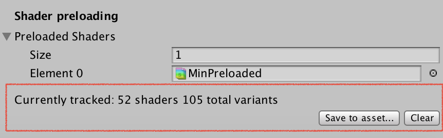
still renders black


did you create the asset via the Project settings button or via the "normal" create asset menu?