#archived-shaders
1 messages · Page 235 of 1
It's already compiled, but pink/magenta means there was either an error or the shader is not compatible with the current render pipeline (target under Graph Settings).
e.g. If it's set to URP, the project must be set up with URP. There's more to just installing the package too, you need to create the render pipeline asset and assign it under Project Settings. See https://docs.unity3d.com/Packages/com.unity.render-pipelines.universal@12.0/manual/InstallURPIntoAProject.html
If you want to use Shader Graph with the Built-in RP there should be an option to target it if in Unity 2021.2+
ok thanks
If you're using URP, I've got a Main Light Shadows subgraph here (and even an example graph included that does this) : https://github.com/Cyanilux/URP_ShaderGraphCustomLighting
Ok tysm, it was caused due to the missing RP
If a Sprite has a TextMeshPro object as its child, and the TMP object sits infront of the sprite relative to the camera, how do I create/write a shader that cuts a cookie cutter type hole in the sprite that's the shape of the TextMeshPro text (based on the SDF info of the text shape).
If you're in URP I think you can use the RenderObjects feature to do something like this rather than multiple cameras. Not sure about other pipelines though. If it helps there's a twitter thread that Ben Golus posted with various ways to achieve the effect : https://twitter.com/bgolus/status/1471197274994667525
with Builtin, try adding a Sorting Group component, and setting the group to higher than anything else.
If there's multiple point lights you might want to check the lightFalloff part of the code since you override the value rather than having it additive lightFalloff +=. I can't see any other reason why it wouldn't update really.
The normal vector is also in object space when it should be converted to world (preferrably in vertex shader). Should be able to use worldNormal = TransformObjectToWorldNormal(normal).
side question: why not use Unreal to make an FPS? It's basically an entire engine specifically designed for making them. A lot of the work has been done for you.
"cookie-cutter type hole" makes me think of Stencil operations, but unsure if that's exactly what you're asking for.
I was aware of the lightFalloff being overwritten, also I thought about the favt that the normal should be in worldspace but didn't know how to convert it
I'd have tried using mul(unity_ObjectToWorld, though TransformObjectToWorldNormal sounds better
So I'll try that
Probably. Is there a way to read the shape of letters from a TMP SDF shader and "stencil" an appropriate hole into a sprite?
Though I tend to think of stencilling as adding paint, like screen printing a tshirt. Perhaps programmers have come up with an alternative meaning, again 😉
In the case of shaders, you can think of it like rendering the TMP object's pixels into a separate screen buffer (stencil buffer). Then you render the sprite testing against the buffer, and it discards pixels that fail the test/comparison.
https://docs.unity3d.com/Manual/SL-Stencil.html
This is a pretty good tutorial that goes over it : https://www.ronja-tutorials.com/post/022-stencil-buffers/
If you're using Shader Graph though, it doesn't have support for stencils (yet). But you can use the RenderObjects feature (in URP) to override stencil values.
Because I enjoy solving problems (read: I enjoy torturing myself)
Am using builtin. How do I read a SDF TMP object's pixels into a separate screen buffer. I see how to do it for alpha textures, and geometry, but SDF TMP objects are a bit... special.
You'd probably need to look at the TMP shaders, I'm not very familiar with them
Though iirc they might already have some stencil stuff under the "debug"? section on it's material inspector
It will be that. Unity is torture when using it for things that it's good at and that you know would be difficult in other engines. I'd hate to be working on something that was almost templated in another engine.
I'm only doing it as an exercise for furthering knowledge of rendering/game mechanics. I'm not actually making an fps
Sadly, no. There "masking" is based on their placards, which are quads for each letter. So have to find a way to "read" the SDF output result. I kind of know the TMP shaders, I edit them a bit... but still haven't found a way to read their output
That would likely be due to rendering transparent (alpha blended). If you use alpha clipping it should then work. I can't remember if the TMP shaders have that as an option though
No, the clipping/masking of TMP is exactly what I don't need, in every way. It's placard based, and determined by an external texture. So you can use a sprite to mask a TMP object, but not get at any info about TMP letter shapes to use them for anything.
If alpha blending were to work (and it should) again the problem becomes "how to read the alpha/content of the TMP object?" so that it can be used as the alpha info to do the cookie cutting into the sprite.
There's been requests for this going back to 2014, but the guys from TMP have never made this kind of masking
@misty plover Is something like this what you want?

Yes, exactly like that!
The TMP shader doesn't annoyingly doesn't expose it's properties for _ColorMask & _StencilOp, and a way to enable alpha clipping (adding UNITY_UI_ALPHACLIP to shader keywords), but I used the debug inspector on the material to hack it.
_ColorMask of 0 means don't write to the colour buffer (makes the text invisible)

Could probably also copy the shader and try to expose options for that but it's using a CustomEditor (bottom of shader), might need to remove that line, or I guess edit the C# script but would probably need to clone the TMP package.
Oh these other two are important too :
_Stencil of 1 here is basically just a random ID, needs to match the stencil pass later
_StencilComp of 8 is "Always", so this object doesn't do any comparison and always "passes"
https://docs.unity3d.com/ScriptReference/Rendering.CompareFunction.html
_StencilOp is what happens when it passes, a value of 2 is "Replace", meaning write/replace the value in the buffer.
https://docs.unity3d.com/ScriptReference/Rendering.StencilOp.html

I think the UI version does expose stencil stuff, to support the built-in Mask component.
The white plane is then using the Unlit Shader template, but with "Queue"="Transparent+1" added to tags (to force it to be rendered after the TMP. Could change the queue on that instead). And with this added inside the Pass :
Stencil {
Ref 1
Comp NotEqual
}
(This basically means if the value in the stencil buffer is set to 1, don't render the pixel)
As far as I can tell it exposes the _Stencil and _StencilComp but not the others
How did you figure all this out???
I just know shaders & stencil operations well I guess 🤷♂️
Could likely also set all these properties from C# if that's easier than using the debug inspector btw
Will have to figure out how. I barely know shaders. But know TMP reasonably well... this is 100% TMP:

Nice, I haven't used TMP that much. It can do some pretty cool things though
THe more I look at and begin to understand what you did, the less I understand how you did it, and how you figured out how to do it!
Massively impressive detective and doing!!!
About this, I have custom mods I've made to the TMP shaders, and I have to revert to them each time I load Unity, as the NPM/Cache restores to original each time, and I've never figured out how to get truly unique (own) shaders to work with TMP, only modding the originals... which requires this "Revert" from Rider's local git each restart. ANNOYING!
Have never done a stencil pass, so expect that when I'm at this stage I will be asking more questions.
I'm trying it out, but it doesn't seem to work


These keep getting better and better with each edit: THANK YOU!!!
Hmm what version is this in? I'm trying 2021.2.5f1 (URP) and it seems to still work. Are you sure the white cube is casting a shadow? Maybe try changing light direction

I am using shadergraphs with BiRP, so I assume that is the issue

Ah yeah, built-in works differently
I think the "Main Light Shadows" node doesn't work with BiRP
And that seems to be the lynch-pin that is causing it to not show
The abbreviation is Built-inRP (or BiRP) technically. "SRP" means scriptable render pipeline which is what URP and HDRP are
Built-in Unity Render Pipeline. BURP.
Sorry, some super stupid questions: is this a quad? How do I add this Unlit Shader template to it, and add tags to it?
Well as far as I can tell the built-in target is using very similar Shadows.hlsl code to URP. I'm kinda unsure why it doesn't work, though I guess the CustomLighting.hlsl was written for URP and has some includes for urp-specific stuff which might be breaking it.
Maybe BiRP (/BURP) is using the _MAIN_LIGHT_SHADOWS_SCREEN keyword instead? Could try copying the graph to your assets and adding that to the blackboard (as a Boolean Keyword, make sure you edit the reference not just the name, should probably be set to Global and MultiCompile).
If that doesn't help, could also try a Custom Function with a hlsl file containing just this. But given the shader is transparent and not pink, I'd assume the file isn't the problem.
#undef REQUIRES_VERTEX_SHADOW_COORD_INTERPOLATOR
void MainLightShadows_float (float3 WorldPos, out float ShadowAtten){
    #ifdef SHADERGRAPH_PREVIEW
        ShadowAtten = 1;
    #else
        float4 shadowCoord = TransformWorldToShadowCoord(WorldPos);

        #if VERSION_GREATER_EQUAL(10, 1)
            ShadowAtten = MainLightShadow(shadowCoord, WorldPos, half4(1,1,1,1), _MainLightOcclusionProbes);
        #else
            ShadowAtten = MainLightRealtimeShadow(shadowCoord);
        #endif
    #endif
}
Right-click in your assets somewhere and you can create a new shader. Create -> Shader -> Unlit Shader. Edit the code then create a material using the shader, drag it onto the quad
I'll test it, also, while searching for a solution I came across your blog post about Shader Graph Custom Lighting Lmao
why does unity do this with the far plane output on the camera node?
I probably pasted it in wrong but I got this:
Shader Graph at Assets/Resources/Materials/Seccondary Shadows.shadergraph has 1 error(s), the first is: Validation: Could not load Sub Graph asset at "Assets/AssetStore/URP_ShaderGraphCustomLighting-main/SubGraphs/Main Light Shadows.shadersubgraph" with GUID f3ba9248037f69f429d9e52bc2e30940.
UnityEngine.GUIUtility:ProcessEvent (int,intptr,bool&)
Before:

after:

I meant put the code in a new hlsl file not the same one.
Though would also have to swap the Main Light Shadows subgraph out for a Custom Function node (might be a good thing since it seems to be erroring anyway). Also need to add those 3 shadow keywords listed in comments to the graph (see the subgraph for an example). But also with the additional _MAIN_LIGHT_SHADOWS_SCREEN boolean keyword
This is causing error: unrecognised identifier "Stencil", do I have to introduce (header) it somewhere?
Make sure you add it to the ShaderLab section of the code (just inside the Pass) and not the HLSL block
These links I shared earlier might provide some examples
https://docs.unity3d.com/Manual/SL-Stencil.html
https://www.ronja-tutorials.com/post/022-stencil-buffers/
Argh, up abobve CGPROGRAM... got it. No errors now, jjust not working... will keep fidddling...
I duplicated MainLightShadows, added the boolean keyword, and made a new hlsl


Still nothing though...
Sorry then, no idea how to get it working for Built-in ☹️
You might be able to find shader code examples online that can do this instead of using graphs
Good idea
Is there anything I have to enable to cause stencil passes to get processed?
Nope, the stencil should just work. It can be hard to debug though since you can't really see the values in the buffer.
The Frame Debugger window might help a bit. Need to make sure the objects are drawn in the correct order (TMP first) (e.g. by changing render queue, that's why I used Transparent+1)
I don't know how to properly code this but I need a shader that renders when the stencil value is 0 regardless of depth testing, and if it's 1, should only render if it passes the depth test
You'd likely need to split this into multiple passes
I guess, ZTest Always Stencil { Ref 0 Comp Equal}
and ZTest Less/Greater/Whatever Stencil { Ref 1 Comp Equal}
:)

It's now "sort of working" in that it's cutting out the geometry of the TMP objects (the quads of each letter) but not the letter shapes
Then the last thing to do should be to add the UNITY_UI_ALPHACLIP keyword to the "Shader Keywords" field in the debug inspector on the material
I'd already done that, but to the TMP object. should this be on the quad's shader?
Hmm no just the TMP one
I can't thank you enough! Got it working!!! It was a typo... spelt UNITY_UI_ALPHACLP without the I clip!
THANK YOU!!!
This opens up whole new realms of creativity for me. CHEERS!!!
i now owe you. If you ever need any graphics, animations or sound effects... hit me up. I'm at your disposal. THANK YOU!!!
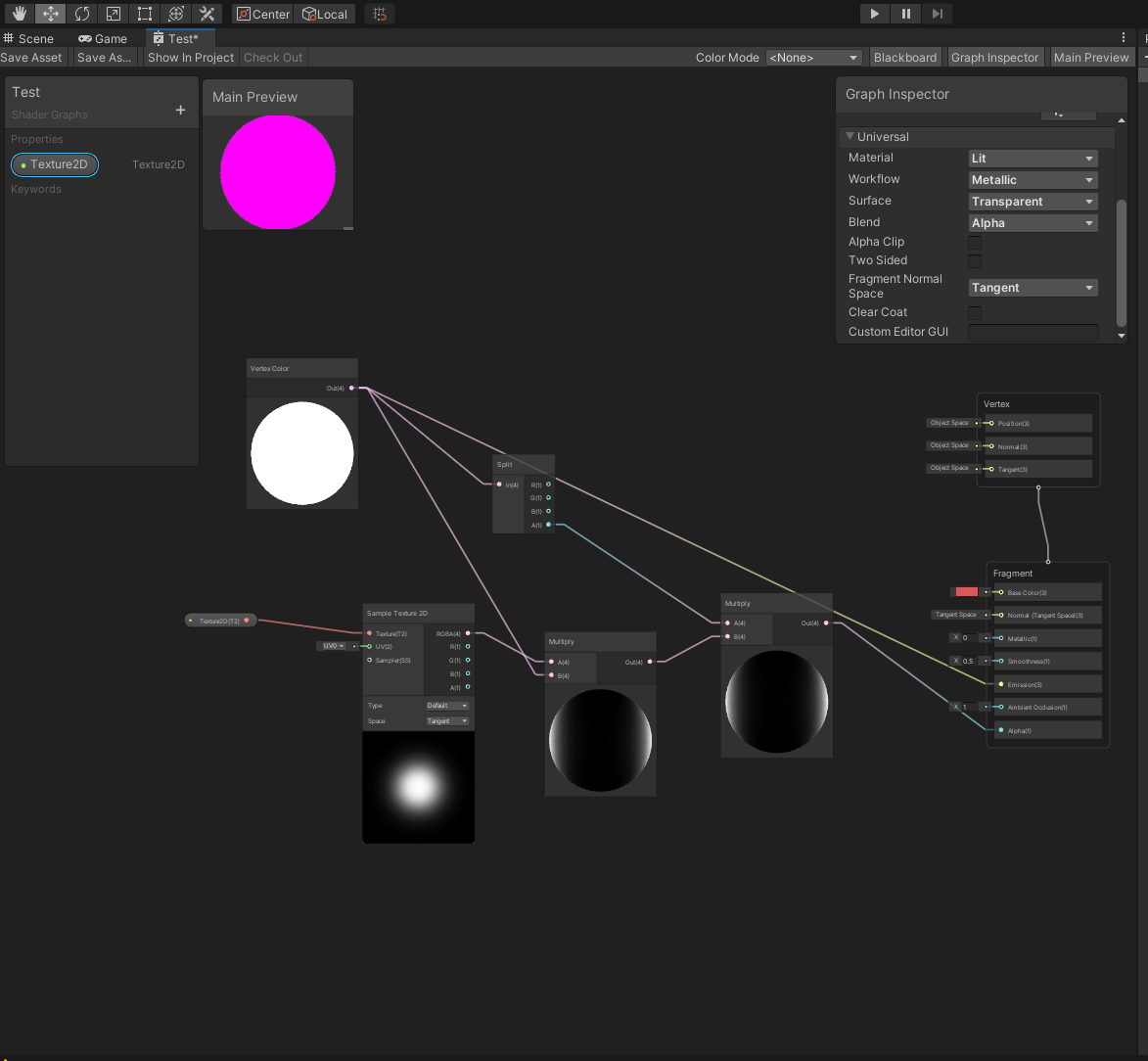
why does he have universal but I dont?

The Universal option would only appear if you have the Universal Render Pipeline package installed. But if you aren't using that pipeline can use the Built-in target instead (if in 2021.2+)
can anybody help me why the far plane output from the camera node kinda breaks when switching from an angle?
It'll be an option on that list, if you're using Unity 2021.2+ that is. Previous versions do not support shader graph in the built-in RP, only URP and HDRP.
i already shown a screenshot yesterday


Can anyone explain why this might be happening? The gun on the left has a standard unlit shader, the one on the right is a custom version of the unlit shader that is only occluded by itself. But there is a brief moment where the pixels of the right gun are occluded but then it pops back to normal
Is this just Unity being Unity?
isn't that basically clipping?
why dont I see built in shader graph?
The gun on the right is supposed to be visible through opaque geometry that doesn't have the same material (or stencil value to be specific), but there is a brief moment when clipping through the wall where it is partially occluded but then it corrects itself
oh yeah i saw that
Does emission/intensity not work in universal shader graphs? the color changes but the glowing effect doesnt happen for me
Don't cross-post.
Yes, it does. If you're not getting bloom then either you haven't added the post processing effect, your threshold is not low enough, or your pipeline is not using HDR (if you want only values above 1 to bloom bloom)


Can I do this to the default Sprite shader?
Unity Performance Optimization Ⅰ: Rendering Module
Two Basic Parameters that Affect Rendering Efficiency: DrawCall and Triangle
https://blog.en.uwa4d.com/2021/12/30/unity-performance-optimization-rendering-module/

How to achieve the best balance between excellent visual effects of the scene and smooth running has always been a headache for game designers, artists, and also programmers.
In-depth Analysis of Unity Loading Module Ⅱ: Shader
https://blog.en.uwa4d.com/2022/02/24/in-depth-analysis-of-unity-loading-module-shader/

Continuing from the previous article of In-depth Analysis of Loading Modules, in which we focused on the loading performance of mesh resources, we will discuss about the loading efficiency of Shader resources for you today. Resource Loading Performance Test Code Like the test code proposed in the previous article, we will…
the last shader topic should be the one matched with the server title 🙂
if I wanted to make something iridescent like this, how would I go about doing that?

I want to get started with coding custom shaders any resource suggestions to get started with?
any urp celshade shader:(?
One of the first hits in Google
https://github.com/Delt06/urp-toon-shader
GitHub
🌔 Toon shader for Unity's Universal Rendering Pipeline. - GitHub - Delt06/urp-toon-shader: 🌔 Toon shader for Unity's Universal Rendering Pipeline.
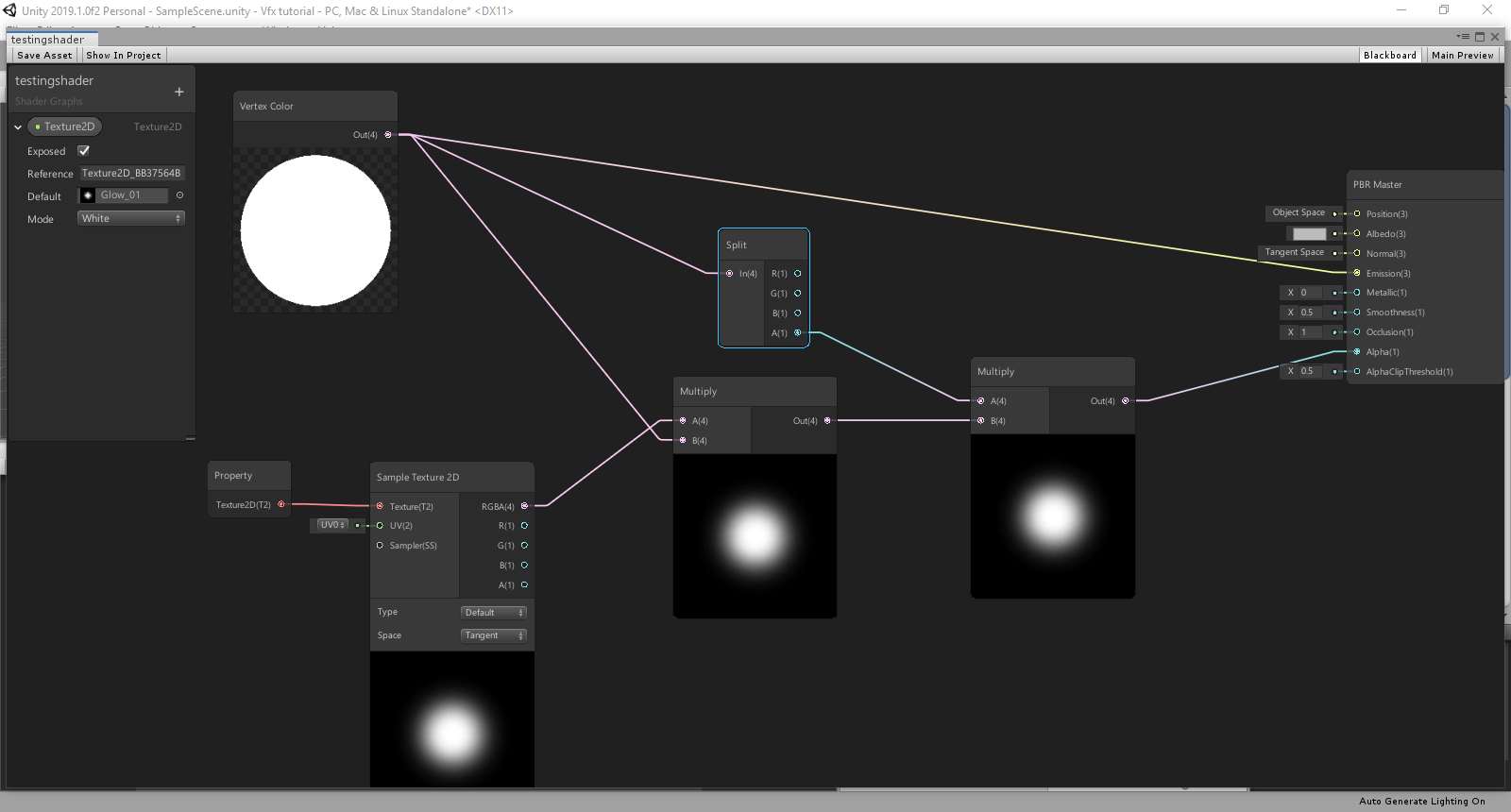
this dont work:(
pink texture
all of the urp toon I downloaded have broken texture:(
am I doing something wrong?
Maybe you're not even using URP then.
Hey guys, a quick question,
Can i get screen texture/color with URP 2D renderer in shader graph?
As I didn't see a 'texture/material' channel, i'm gonna go with shaders since it's the closest thing. Basically, I want to know how people get very good looking textures, with reflection, displacement and all. I downloaded some high quality textures off of ambientcg.com (previously cc0textures.com), but i'm not seeing any inputs for roughness maps, ambient occlusion maps, displacement maps and metallic maps.
Check out Freya Holmer's videos about shaders. They're a bit unstructured but they have a lot of valuable knowledge: https://www.youtube.com/watch?v=kfM-yu0iQBk

Welcome to my three part lecture on shader coding for game devs 💖 I hope you'll find this useful in your game dev journey!
If you are enjoying this series, please consider supporting me on Patreon!
🧡 https://www.patreon.com/acegikmo
00:00:00 - What are shaders?
00:03:00 - Case study/screenshots from FFXIV, Overwatch & more
00:37:42 - The Struc...
I also have an (incomplete) Google Doc detailing the various uses of different features of shaders that might help: https://docs.google.com/document/d/1lot50tKzuEQrYwRzmeUXDesIfpZ-T_DRenLLKiEBJCU/edit?usp=sharing

Google Docs
Explanation of Shader Terms This document is meant to be an in-depth explanation about what various variables, functions, macros, and keywords used in Unity Shaders mean. It applies to version 2020.3.20f1 of the Unity Editor. All shader code is written in Visual Studio 2022. Shader This is the to...
If I wanted to make it so that a texture was only visible when on a vertex facing the camera (in the same way that a fresnel effect would make a certain color only visible when facing the camera), how would I do that
You need to convert the normals to camera space. Then when you are adding the texture sample color in the fragment shader, you multiply it by the dot product of the camera space normal and the vector (0,0,1) I think.
I understood like a tenth of that I'm gonna be real with you
I'll break it down:
- Convert object normals to camera space
If you don't know what a normal is, it's a vector that specifies the direction a pixel is facing. Imagine positioning a pencil so that it is perpendicular to the surface of a table. That would be the table's normal at that position. That said, the normals of an object are by default in object space, which means the normals are relative to the object (i.e. the mesh) itself. This means that no matter which direction the object is facing, the object space normals don't change. In order to get the normals relative to the camera you need to do matrix multiplication on the normals, but Unity has a helper function I think for doing this quickly.
- Take the dot product of the camera space normals and (0,0,1)
Imagine you are the mesh. In object space (also called local space), your face normal is always pointing (0,0,1) which is forward in Unity. However, if a camera was looking at you so that you appeared to be looking to the right, that same normal would be (1,0,0) relative to that camera. The dot product of two vectors is useful for figuring out how close the facing direction of two objects is. For instance, if the vectors are the same, the dot product is 1. If they are at right angles to each other, the dot product is 0, and if they are going in opposite directions, the dot product is -1. This is assuming both vectors are unit length (also called "normalized"). In other words we are taking the direction you are facing relative to the camera (1,0,0) and dotting it with the direction the camera is facing, which is always (0,0,1). Because they are at right angles to each other, the dot product is 0.
- Multiply the sampled texture color by this dot product
For simplicity purposes, let's assume the shader is unlit (it doesn't use lighting). In the fragment shader, you would just return the raw color of the texture sample. But to get the fresnel effect you want, you need to multiply that color by the dot product we calculated earlier. This in effect, will make the texture color contribute less and less the the more it faces away from the camera
Had to split this into two messages because it was too long
Okay perhaps I should recontextualize my question
I have no clue how to make a shader from scratch
like I've been trying to figure out how to do this using Poiyomi Pro if possible, since I'm making this for a VRChat avatar, but anything in regards to actually coding the thing from scratch is way out of my capabilities
I'm using URP and trying to write a vertex displacement shader from scratch, it works correctly in the game view but for some reason displays incorrectly in the scene view.
Any ideas why? (first tree on the left)

Do you know any ways to do this using pre-existing shaders?
I could write one, but I don't know how it would translate to VRChat. The same principles would apply though. I'll see what I can come up with
Hello, I was wondering how to put all the different maps you get from downloading a texture (displacement, ambient occlusion, metal, roughness) into unity. I'm not seeing any slots for them, only for normal.
You need to use a material that uses a shader that includes all those maps
If you don't mind, what's a shader and how to set it up?
I am using URP- im dumb but im not that dumb
Ok
You don't need to set up a shader, there already exists one that you can use. By the way, shaders are technically just programs that run on the GPU, but more generally they are programs which take in data (like mesh vertices and textures) and produce colors on the screen
I don't know if it's available in all render pipelines, but if you create a new material, by default it uses the Standard shader, which includes support for all those texture maps
Oh I think I see, it says it's using HDRP/Lit
So I should be using standard?
I don't know if it's available in the HDRP, but if it shows up in the dropdown then sure
I am using the built-in render pipeline right now
Makes my material all pink
Doesn't. hum, so should I recreate my project another way to have it like you?
as long as it works with the standard render pipeline, I'd imagine it would work fine
but actually instead of facing the player, it probably makes more sense for it to only be seen on surfaces reflecting light
Are you sure the HDRP/Lit shader doesn't have the features you want?
Yup. No slots for the maps I want to use
"VRChat does not use the HDRP or LWRP/URP rendering pipelines offered by Unity."
oh nvm
thought you were replying to me lol
That's still relevant lol. It probably uses the built-in render pipeline then
HDRP uses a "mask map" that combines some textures (Metallic, Occlusion, Detail Smoothness) into one. See https://docs.unity3d.com/Packages/com.unity.render-pipelines.high-definition@13.0/manual/Mask-Map-and-Detail-Map.html
yeh
oh boy that looks complicated. Mind dumbing it down for me please? :/
but yeah I guess a more clear way to describe what I'm looking for is like if this was used as the alpha for this


It's basically putting each of the greyscale textures into the colour & alpha channels of a single texture.
I've used tools like this to handle it before : https://github.com/andydbc/unity-texture-packer (but not for HDRP specifically, I mostly only work in URP. I imagine the tool should still work in any pipeline though)
Also https://github.com/phi-lira/SmartTexture, but I couldn't get that one to work last time I tried to use it
Alternatively can use imagine manipulation software (Photoshop, GIMP, etc) to combine them manually
Thank you!
Should basically be able to do lerp(baseColor, secondScreenshotColor, firstScreenshot);
It sort of works, wich is better than nothing
like I said, idk how to make shaders from scratch lol
idk anything on the coding side of unity
How to convert blender materials to unity???
if you're willing to write one, how long do you think it would take to make?
Should it look like this?

I think what I was thinking originally would be like that yeah, but I think I should probably have it be relative to the light source instead of the perspective
You mean that the lighter the pixel is the more opaque it should be?
yeah pretty much
https://youtu.be/gtUQjJXICpI?t=59 this shows the effect I'm after pretty well

Angel Aura Quartz is a beautiful type of crystal coated in precious metals, such as platinum, nickel, gold and titanium. It is then heated in a kiln to facilitate this alchemical process. The holographic tint is due to this alchemical manipulation of a regular quartz crystal.
Angel Aura Quartz works on all chakras due to the rainbow effect
Sh...
with this kinda surface sheen only visible when the light hits it

I believe that's called "pearlescent"
Sorta, although pearlescence is moreso a fade from one color to another wheras this would be from transparent to a texture, since the color that reflects off the crystals doesn't change with perspective
I think a more knowledgeable shader dev would be able to help with that. I just struggled for an hour trying to convert object space normals to view space lol
I'm still learning this stuff myself
Lol my bad, you did a really good job with it tho. Mind if I grab it to see how it'd look with what I'm going for?
#archived-shaders message would this be able to help in any way?
Normal map preview is full blue

how do you generate high poly objects? i tried to import Blenders sculpting sphere, but my shaders still treat it as one big vertex
Maybe ask in #🔀┃art-asset-workflow ?
Or maybe you should post a shader question, if your shader is messed up.
well it has to do with my shader. im trying to make a wave shader that makes the sphere have ripples that go up and down, but yeah your right thats probably a better place to ask
Well, there's no such thing as "one big vertex" so IDK what you're asking, about the shader or the import?
P.S. water shaders often use planes, not spheres.
yeah ik, im trying to make a cool science gun with a shaky sphere out the back. Ive got my shader working on a sphere right now but im trying to import a more high poly sphere so the waves will be smoother. When i try to import one from blender the sphere just scales up and down rather than having waves go across the surface
OK, now that is probably a shader question. Want to post your shader so we can tell what's going on?
You can use pastebin or whatever.
sure, how do i post a shader graph to pastebin?
Meh, see above. Most people post a pic.
But it sounds like your shader is applying the same offset to all verts.
However many of them there are. Probably in the right direction though.
So that's a start.

this provides this effect

with is nice, but the waves can be "spiky" if you know what i mean
the shadergraph image is clearer if you open it out of discord
The "spiky" thing is partly a function of how many verts your sphere has. But you clearly have several. Also, IDK what the mesh looks like, but not all spheres are created equally. Some are merged at the poles, and others are made out of soccer-ball type of chucks or other polygons.
Then there's the challenge of calcing a new normal based on your adjusted verts
Yeah, that's not a good sphere to use for this, IMO. It's good for other things. Depends on usage.
yeah i know, thats the problem. how do i get a better sphere?
Well, blender, but you have to recalc the UVs.
There's https://en.wikipedia.org/wiki/Geodesic_polyhedron

A geodesic polyhedron is a convex polyhedron made from triangles. They usually have icosahedral symmetry, such that they have 6 triangles at a vertex, except 12 vertices which have 5 triangles. They are the dual of corresponding Goldberg polyhedra with mostly hexagonal faces.
Geodesic polyhedra are a good approximation to a sphere for many purpo...
Google is your friend, IDK if blender has that built-in or as an add-in or not.
ive tried googling this problem. "Unity how to get high poly sphere" doesnt show anything relevent
Try this
https://thenerdshow.com/domes.html
Blender has a geodesic dome, two would make a sphere.

Sorry for the interruption, but i got a question. so i'm planing to have vehicles where you can add decals to them like racing stripes. I want them to always have a main material applied to them for the main color (that can be change by the player) but also a decal material layered on top of it that can be changed by the player. i've heard that shaders can do just this so im wondering what would be the easiest way to do this in preferably shader graph?
that doesnt seem like a lot of vertices compared to something like this:

Blender has an "Icosphere" which you can use too. Cube-sphere isn't too bad, I doubt you need it quite that tessellated though.
Make sure you UV map it too, or change the shader to use something like triplanar mapping
The thing is that generally speaking you don't generate meshes in shaders. You can, with geometry shaders and compute shaders and drawProcedural calls, but that's really not what you need here, I don't think.
That's sphere looks like a highly tessellated cube-sphere.
ok then im confused, more vertices means a more smooth animation along the surface right? is that not like a LOT of vertices highlighted along the sphere?
Yeah, but define "a lot". 😉 Generally, no more than what it takes to make it look good.
but more = smoother = looks good?
Not automatically. Smooth shading is doing very good job making low poly objects look smooth
well this discussion began because a low poly object doesnt look smooth
Oh yeah in this case more vertices could look better but I highly doubt youd need that much
Obviously more vertices = more work = worse performance
What's really bad is when a high-poly mesh is off in the distance, where all 3 verts of a polygon merge into one rasterized pixel, or close to that.
#archived-shaders message I'm still stuck on how to get something like this working
Hence the idea of having at least one level of LOD reduction
ok, i watched a vid on how to generate UV maps, and now the blender sphere import looks great
Yeah, that explains why you got a same-value expand/contract for your sphere, since all UV's were 0,0.
But you still need a geodesic sphere, IMO.
yip, luckily blender has a tool to automatically generate them
right, this was just a test, ill look that up
ok, im looking at it, and it looks like a reaallly low poly sphere. like, lower than unitys built in sphere i was using earlier
Are there options?
Or can you sub-divide it?
im looking into that now
it seems blender doesnt have a higher one than this

not one i can find at least
You can change the resolution right after you have created it
oh youre right, i see the sub menu. i can increase the polygon by increasing the "subdivision" count
hmmm, using the shader on this one makes it look kinda goofy

compared to what the other sphere looked like

You're getting closer, but like I mentioned above, your normals aren't going to be correct. You have to manually calc them, that's often done by sampling several points (like 3) close around the vert and using them to calc a new normal vector.
blender has an option to recalculate normals, im trying that now
Yeah, but you're MODIFYING the vert positions in the shader, so you have to recalc the normal. 😉
Can set the mesh to smooth shading. Highlight all faces then use Mesh -> Shading -> Smooth Faces
It's a sphere in blender.....
Just referring to fixing the breaks in the mesh in that screenshot. If the shader needs to be lit then yeah you'd want to calculate normals in that too in order to get the correct shading after displacement.
that worked. nad yeah the shader is unlit
thanks for the help fellas, ive learned a lot about shapes here
You want it unlit (mono colored)? If so, you may only need some circle math.
how do you mean?
I mean, all the "inside" of the thing is the same color....blue in your example. The only thing that varies are the edges of a circle.
But for 3D you'll need some kind of lighting to see waves on the "front" of it.
ohh yeah i see your point
Even a simple NdotL, but for that to happen, you need surface normals.
Depends on what you want to achieve.
yeah im going to have to expiriment with this
If you do want to recalculate the normals in the shader too, this tutorial should provide an example (though it's code not graph) : https://www.ronja-tutorials.com/post/015-wobble-displacement/
It's a similar idea to what Carpe was talking about earlier with sampling points near the vertex (using the tangent and bitangent vectors here). It also uses Sine, but should be able to swap that out for your own displacement. It's the various points and cross product that's important.
maybe thatll fix this wierd pizza slice issue im gettting
up hold on, let me convert that to mp4

theres the shader attached to it
That's due to seams caused by the UV mapping
how would i fix that? for right now im going to try to have blender regenerate them
The other problem you're going to hit....is that there is no way to map a sphere to a 2D square. So IDK what blender is generating for texture UV's. Map makers have this problem all the time, which is why maps are so distorted, or cut up.

lol. Yeah. That.
ok, after regenerating it now looks like this:

If you're doing ripples it might make more sense to use the 3D positions (Position node) instead of UVs
i mean, its going into the positions node in shadergraph. is that now what you mean?
No, I mean here you use the UV node

ohhh i see
Yeah, if you're not trying to map a texture to it....
If you want a texture, that's where it gets tough.
Otherwise, @regal stag is right, you don't need UV's to just modify the vert pos. But you were using UV's to sample your noise texture. IDK how to map the 3D pos to a 2D noise map.
ok, i replaced the UV node with an obkect position node, and the preview in the bottom right looks good, but now the balls are back to pulsing
There's a direction vector from the center of the sphere to the vert position. You can shrink/expand along that.
But how do you decide where to look up the amount in the noise texture. That's where we get back into 3D to 2D mapping.
Are you still offsetting the position before using the Length node? If you aren't the ripple would be starting at the center of sphere, hence why the whole thing pulses at the same offset.
yeah, it looks like this now

Swap the Vector2 node out for a Vector3, and set it to something like (0,1,0)
That should start the ripple at the top of the sphere then (assuming the object scale is a unit that is, might be 2 if it was using the default scale from blender)
it does, but now it goes halfway in a sort of step effect
All this reminds me of those "spherical mini-planets" where they do a height mapped terrain.
There's several tuts for them on youtube.
Probably need to change some values around the time node to make it go further. The step effect might just be because that sphere preview doesn't have enough vertices again (better to check in scene view). And maybe the ripple width is too small. Idk
this one?

yeah im playing around with it now, the time scale only seems to affect speed, not how far it goes
Sure, that's one. I like his vids.
I don't recall how he did that mapping though.
Maybe do another multiply after the Fraction node
yup, it goes to the bottom now. But im still getting a pulse effect on my blender spheres
works great on normal unity spheres
Perhaps a difference in the scale of the model then
is there a way to use commandbuffer to draw directly to screen (camera render target)
commandBuffer.SetRenderTarget(MainCamera.targetTexture);
commandBuffer.DrawProceduralIndirect(...)
This isnt showing up to screen at all even though Im rendering a fullscreen triangle
Sometimes when importing Unity likes to default blender stuff to a size of x100. I think unticking the "convert units" on the model import fixes that. (Though I'm sure there's also settings in blender that can be changed)
BOOM that was it, looks great now
we now have a smooth beautiful boy
Try replacing the drawProcedural with a drawMesh and a simple shader material, does it draw? If so, it's your draw-procedural that's the problem.
the preview on my material looks perfectly fine but yeah i should try that
so does the output texture in renderdoc
Hmmm
Cameras sometimes render to render textures and not the back buffer, but since you set the same render target, IDK.
I imagine .targetTexture is only useful if the camera has a Render Texture object set as it's target. If it's just a regular camera rendering to the screen it probably uses a different target.
renderdoc capture says my stuff is drawn first and then everything else is drawn so my drawprocedural is probably getting drawn over like it never happened
Oh, obliteration. Not fun, but that would explain it. 😉
yeah its render target is null which normally implies render to screen
atleast when you use Graphics.draw commands
IIRC, there's a way to set the render queue number
Or control the order, so that you can do your draw AFTER the camera draws.
Maybe try commandBuffer.SetRenderTarget(BuiltinRenderTextureType.CameraTarget)
There are events.
Yeah, assuming built-in RP, Camera.AddCommandBuffer has an event param
I'm using universal RP right now
Did anyone ever figure out how to make a shader that only shows a texture where light's shining on the mesh?
Then you'd typically use a Renderer Feature. As long as you don't call ConfigureTarget it should already automatically be set to the camera targets, don't need to use SetRenderTarget.
What does it show when there's no light on it? Transparent?
Black? What?
transparent is the goal yes
OK, use a transparent shader, and for the self-lighting, check the light value and set the alpha accordingly. Conceptually, that's what you'd do.
Now doing that in a lit-shader in shader graph, IDK. But if you're calcing lighting yourself in unlit, you can. Or edit the generated shader.
There's self lighting, and environment lighting. Basically.
So what do you mean by "light's shining on it"? Because there's multiple sources of light. You didn't think this would be easy, did you? 😉
in reference to the environment light
And then what about shadows? Will that become transparent?
the shadow is ideally what would become transparent
but it can't be done in shader graph since VRChat doesn't support that
So that means checking a shadow map.
What it sounds like you really want is to make it transparent where it is in shadow. Aka NOT lit. Kind of the logical-reverse of what you asked, if that helps clarify it.
Yeah pretty much
Because that includes shadows from OTHER objects.
#archived-shaders message this shows the effect I'm going after
Yeah, that's different.
I'd research "Gem shaders".
Trust me, I have lmao
All of them use fresnel effects, which are relative to the camera, not the light source
if you're trying to do the shimmery sparkly thing you can do it with randomly scattering and scaling uvs and using a particular texture with gradients
Some use refraction, and the screen background, with color effects (to make it whiter-transparent) on top, then there's your rainbow
I'm gonna use refraction as well, but specifically I want the surface reflection
the simmering looks like this
https://en.wikipedia.org/wiki/Thin-film_interference

Thin-film interference is a natural phenomenon in which light waves reflected by the upper and lower boundaries of a thin film interfere with one another, either enhancing or reducing the reflected light. When the thickness of the film is an odd multiple of one quarter-wavelength of the light on it, the reflected waves from both surfaces interfe...
someone on here earlier typed something up that's really close to what I want, except they did it with a fresnel effect

works best is the surface has smooth displacement on the faces (going the fresnel route in this case)
wym, like smoothing out the edges?
nah, sec
yeh, if you make the platinum coating on the crystals super thick and not transparent at all it looks like this

well, if you want to pay Alan Zucconi $8 you can learn a bit about thin film interference and get an example shader
https://www.alanzucconi.com/2017/07/15/the-nature-of-light/
I did that once, but I forget what the context was
Rough and ham fisted

Probably'd do the rough stuff with a normal map rather then actual geo
I don't think I need the normal to be wacky or anything, the texture I linked earlier works fine
also is that made in the standard render pipeline?
If you mean Alan's work, yes
Oo, I might check that out then
If you mean mine its made in blender but shader graph, big boy hlsl can do the same thing pretty easily
VRChat doesn't support that lol
ah 🤦♂️ sorry
all good, you were prolly working on it when I mentioned it
ha, no but I've done similar in the past.
(that's why I banged it out in blender)
oh lol
But yeah this is the shader I got sent earlier, it has the exact look I'm going for, it's just showing the texture in the wrong place ```Shader "Unlit/FresnelTexture"
{
Properties
{
_MainTex ("Texture", 2D) = "white" {}
}
SubShader
{
Tags
{
"Queue"="Transparent"
"RenderType"="Transparent"
}
ZWrite Off
Blend SrcAlpha OneMinusSrcAlpha
LOD 100
    Pass
    {
        CGPROGRAM
        #pragma vertex vert
        #pragma fragment frag


        #include "UnityCG.cginc"

        struct appdata
        {
            float4 vertex : POSITION;
            float2 uv : TEXCOORD0;
            float3 normal : NORMAL;
        };

        struct v2f
        {
            float2 uv : TEXCOORD0;
            float4 vertex : SV_POSITION;
            float3 normal : TEXCOORD1;
        };

        sampler2D _MainTex;
        float4 _MainTex_ST;

        v2f vert (appdata v)
        {
            v2f o;
            //the float3x3 is because we are transforming a normal rather than a point
            o.normal = normalize(mul((float3x3)UNITY_MATRIX_MV, v.normal));
            o.vertex = UnityObjectToClipPos(v.vertex);
            o.uv = TRANSFORM_TEX(v.uv, _MainTex);
            return o;
        }

        fixed4 frag (v2f i) : SV_Target
        {
            float fresnel = (dot(i.normal, fixed3(0,0,1)) + 1) / 2;
            fresnel += 0.05;
            fresnel = pow(fresnel, 10);
            if(fresnel > 1) fresnel = 1;
            // sample the texture
            fixed4 col = tex2D(_MainTex, i.uv);
            col.a = fresnel;
            return col;
        }
        ENDCG
    }
}
}```
the color is based on the uv coordinate
yeh I know that lol, I mentioned that it was fresnel based and not light source based
would this be able to fit in the place of anything in this code?
how do you reference scene game objects using a render feature
hey so sometimes, when I run this, for the first bit above the loop, iter is 0 as it should be, but usually its not, it seems to set iter(in the loop) before the initial compute shader is dispatched(which yes I know does happen), how do I make not do this?

How would I get this blurred outline effect?

just an uneducated guess, guassian blur on the texture?
How do I choose to not draw a pixel in a vert or frag function in shader code? Afaik, i have to return a v2f in vert or a fixed4 for frag.
nvm, apparently i can use discard; in frag function
What would the equivalent of UnityObjectToClipPos(); be for light sources?
All materials from blender appear much darker in unity. How do I fix it?
is your base color maybe not white?
I'm trying to make some 2D hexagons be slime blobs, and I'm not really sure how to go about it. I was hoping someone might be able to point me in the right direction for figuring this all out. These slimes will slide along each other, squishing in the process. They should keep a fairly constant volume. Though this is more of a later concern, I also want to be able to apply some very basic physics to them for animation purposes (no actual collisions beyond them squishing against each other slowely, thank god).
I have a bit of experince with shaders, though it's been a while. All I can think of for this though is drawing them to a texture and trying to squish them based on if there's any overlap, and ideally just in general for some smoothing. I could also mimick physics by feeding in velocity information in another texture combined with the squishing they've just done and pulling them based on that. Their face sprites are subject to actual physics, so I could probably leech a lot of the work from that. Does this sound like a good way to go about it? Anyone have any resources I could learn from for something like this?
Here's a gif of the soon to be slimes in action if that helps. https://imgur.com/IvjOoix

hi does anyone know, how to create float array in shadergraph and iterate over it?
you'd have to write a custom function for that
This should provide an example : https://www.cyanilux.com/tutorials/intro-to-shader-graph/#arrays
blobby slimes are often done as metaballs. ever heard of those?
I have not. Is that what water sims are made of?
Some use it in some capacity, sure.
It’s used to create that surface tension look between blobs as they approach each other
Ok, well this has given me something to go off of that's more than 'complicated math stuff', or at least it's a well documented complicated math stuff. Thanks.
Thanks @regal stag
Hey, I'm having a hard time figuring out how to get my render texture to be in the right sorting order. Is there a way for it to appear in the sorting order than it has initially?
From what I've seen on Google, enabling the depth buffer is supposed to do just that, but it doesn't seem to work for me
if you render to a texture then it's not in the screen buffer, right? it's gonna be in its own texture, that you put wherever you want in the scene, on its own surface. that surface should sort by itself.
are you looking to blend two scenes rendered with different depth buffers?
So I'm having to use render texture in order to make my characters fade, as they are PSB (just changing the alpha of each sprite makes it weird since some sprite are superposed). The surface I use is a quad, which for some reason was the only one I could make work.
then just make sure whatever quad you put your texture on is in the right place in the scene, and uses a depth-aware shader/material
it's easier when it's just 2D objects made of sprites
So basically, all I can get is one surface which is on one sorting order right? I wanted to make an object that's between 2 of the sprites that are gonna be rendered in texture, so that wont work
you can do that
I'm interested 🙂
I'm using sprites/default, maybe that's where the problem comes from?
are we looking at this kind of scene?
C< ATB
where C< is the camera, T is all of your target's sprites grouped together, and A & B are just scene elements
Hello! any ideas to fix this? I have tried activating/deactivating antialiasing, the same as with dynamic resolution and it is still the same

aliasing is a very old problem
doesn't have a lot of elegant solutions
https://youtu.be/gtUQjJXICpI Someone yesterday typed up some code that gives me the rainbow-y reflection effect seen in this video except they used a fresnel effect instead of making it in reference to actual light sources. How would I set it up to do that?
Angel Aura Quartz is a beautiful type of crystal coated in precious metals, such as platinum, nickel, gold and titanium. It is then heated in a kiln to facilitate this alchemical process. The holographic tint is due to this alchemical manipulation of a regular quartz crystal.
Angel Aura Quartz works on all chakras due to the rainbow effect
Sh...

So on the left is scene view, where the fireball is behind the player, and on the right is game view, where the rendered texture goes behind
The player is made out of several sprites
the fireball object just needs to be deeper into the scene, then, no?
or the quad with the player's rendered texture could be pulled closer to the camera
if they're just sprites in a 3D scene it should just work, unless you got stuff specifically forced a certain render order
I don't actually know how to change the sorting order of the quad
position along the Z axis
think of it like you're holding a stack of playing cards. your fireball card is at the top of the deck, and under it you have your rendered player character card. you just need to shuffle that fireball card deeper into the deck
it's just a physical position in the scene, distance from the camera
in the most basic 2D configurations it just means a greater Z position value
I guess the problem is that I use the sorting order for everything else except that
so you do use sort order in your materials?
probably best not to
you wanna use "physical" positions to automate sorting
that's what my cards analogy kinda visualizes
I'm just curious about that part, how do I know if a material is depth aware?
Cos I'm pretty sure this setup used to work, maybe I changed something or updated a package and it changed the material
i think that it depends on the context, but to keep things simple: they almost always are, unless they're some kind of overlay type of effect.
if you use unity's default UI shaders it should work fine (as long as you don't use them in a canvas. canvas does sorting a bit different)
That might be the problem then
your game is based on canvas?
I put everything in a canvas without thinking much, I'm pretty sure most of the stuff doesn't need to be in canvas
In the combat scene at least
yeah, ok, it's not the end of the world or anything, it's just probably pretty inefficient for that purpose.
but that does make some things easier
canvas sorts by order of children in the hierarchy
Yeah, that makes it complicated if some spells have to be above and some behind the players and stuff
I used canvas and overrode sorting when needed to
and that's why usually it's done using physical positions 😛
So Z axis?
I mean I've done that part more than a year ago and went with it, probably had to at some point
all a part of the learning process 🙂
(like basically everything I did)
True
So I could animate a spell and change its z coordinate and it would basically be able to change its order
yup
I can see how that might be useful :p
Didn't really plan to redo all that but it is what it is
stuff gets rendered back to front, so stuff behind draws first, then the closer you get to the camera things start to overlap each other.
this is relative to the camera, i mean
so if your camera's rotation is identity, it is just the Z value
Just one thought tho, how would I make it so a sprite is between 2 of my player's sprite? Would I need to render the texture twice with different z values??
i think maybe for those special cases you might need to bring those pieces into your player's render texture space
i.e. the camera that renders the player texture will also render that piece you wanna include in between the player's parts
it can get hairy, though, so make sure whatever system you come up with knows how to bounce objects between 2 cameras as needed.
Makes sense, I only have to change the layer of the sprite for it to be rendered
precisely 🙂
it's funny, very recently i worked on a similar thing. we had a 3D character that we wanted to appear in UI under certain circumstances, so I came up with a render-to-texture system that allowed for smooth transitions and fading through existing UI elements.
What circumstances? I'm kinda curious to know how that's useful
mul(vertex, unity_ObjectToWorld) is the correct order right?
How do i do a shader for a overlay canvas image, that will fade the images left and right, from the center?
No, the other way
some light from gems comes from like interior reflections. it's challenging to fake. have you read about the physics?
And make sure vertex is a float4 with w set to 1.
thanks
@outer jetty you've thought about this. sample cubemaps and simulate internal bounces.
The reflections I'm talking about are just that, purely reflections. I'm not talking about the stone, I'm talking about the platinum coating
It shouldn't be hard to do for someone who knows unity, since the effect I'm looking for is on basically every shiny thing ever made in Unity with the white sheen they usually get when light hits it
I just need that to be the same thing that reveals that platinum coating texture
Problem is, idk C#
@outer jetty Are you using a renderpipeline? Maybe HDRP ?
Asking this because it greatly looks like iridescence that is a shader option built-in the HDRP/Lit shader
standard, making it for VRChat
Hello, would someone know how I can get rid of this ugly reflection spot on my water, or at least make it look better ? ( first screen with smoothness at 1) (Im in HDRP)

smoothness at 0.8 :

I think it is a form of iridescence, but it's tricky because the colors of that platinum coating don't actually change place on the crystal, only transparency
so it's not gonna be something achieved with matcaps
I don't have a solution here, but applying some rainbow(ish color ramp on the specular reflection might do the trick ? But without some knowledge in shader coding that's not an easy task
I'm looking to be able to use this specifically https://assetstore.unity.com/packages/2d/textures-materials/metals/zinc-iridescent-colorful-149135#description

Elevate your workflow with the Zinc Iridescent Colorful asset from Lex4art (Techkind OU). Browse more 2D Textures & Materials on the Unity Asset Store.
Since that's like identical to what the glint needs to look like
This just looks like a regular specular reflection. You should be able to get rid of it by switching to specular surface type and set the specular color to black, but you will also loose it one the waves themselves.
You can also disable specular lighting on the light itself
For example, there's another variation of Aura Quartz that has so much platinum coating that there's no transparency at all and it's just that texture

But of course that's not what I'm after
Worked thanks
So, hum, if you've found this material, why not use it ?
cuz that's all it is, a texture
well I mean I am gonna use it
but not as is
final product's hopefully gonna look like this

someone yesterday wrote something up for me that does give the coloration I want, but as a fresnel lens instead of in reference to actual light
apparently all I'd need to do is swap out the vector of the camera for the vectors of light source directions, but idk enough about Unity to do that
Is it really ? It mentions a "material" on the store page :/
It's got the glossy finish and all, it is a material, but it's that solid material alone
let me show you what it should look like
since that fresnel lens one does work
ofc, this is layered on top of a crystal shader as well though

You might want to look into custom lighting in surface shaders : https://docs.unity3d.com/Manual/SL-SurfaceShaderLightingExamples.html


Ima be real with you idk enough about coding in general to figure that out anytime in the next month lol
if I sent over this shader, do you think you'd be able to figure out what changes need to be made?
Like, specifically? I know the general changes that need to be made I think lol
what causes the water from dissapearing behind my waterfall ?

a mesh is built out of triangles, and the triangles only have one side, the other is see-through. The normal of all sides here are outwards.
even though the shader is transparent, it cannot be rendered unless you're looking at the mesh from where the normal of the surface is.
scratch that, I misunderstood the question.
It looks like If I have 2 transparent shader and look trough them, it erase the one thats in the back
Hi
Im tryna make the water have a neat transition towards the shore, any ideas on how I could do that? im using Gerstner Waves by Zicore in HDRP. If you have an idea feel free to ping me

Hey,
I'd like to share some code between URP and HDRP shaders but first I'd like to know how to differentiate, in the shader, between one and the other. I can see that a lot of #defines are contained in auto-included files like 'HLSLSupport.cginc' but I can't see anything that'd make it obvious that a shader file is being compiled as URP or HDRP.
HLSLSupport.cginc is more for the Built-in RP.
I'm sure there are various defines included in each pipeline's ShaderLibrary but it may also be easier to define your own keywords. e.g. use #define PIPELINE_URP before the #include ...
Not sure how to do that in this case - the base shader is a shadergraph and the file(s) I'm including are custom functions within that.
Ah, didn't realise we were referring to shader graph
In that case could try using #ifdef UNIVERSAL_PIPELINE_CORE_INCLUDED
Im not very familiar with HDRP so unsure if there's a similar "core" include that would always be included for a HDRP shader graph. Could check the generated code to see if there's anything useful.
Otherwise could use #else and just assume it's HDRP (but that'll only work if the only targets the graph will use are URP and HDRP)
cool, that looks like the #defin I was looking for 🙂
all this would be a lot easier to manage if it weren't shadergraph tbh but that's what my boss wants, so that's what he gets 🙂
I think shadergraph ultimately gets output as shader code but I don't know where it goes
You're using a value of 0 in your Comparison node (coming out from the alpha channel of the main texture sample), so your branch is always true
so im working on this cloud shader an my alpha channel isnt really working the way I want it to. I put my Alpha on 0, which should make it completely transparent but I can still see it.

how can I fix this
thats the shader

from the words of remy from one of my questions that is basically the sames as yours:
refractions don't stack up
rendering transparent objects is tricky
Can you raycast in shader code?
Not to the physics engine
even in compute shaders?
yes even in "computer" shaders
dang
Trying to get a blob shadow always painted with ZTest Always but multiple blob shadow are painted from the projector.
https://streamable.com/enxqsk

thought i could do a raycast to get the blob shadow painted once
also thought i could do distance invariant to discard pixels, but it's still shotty with ramps and meshes close to eachother
would be a big problem on angled surfaces that are deep/steep
would creating a custom pass help ? Ive managed to make the lake render trough my waterfall by using the pre refraction model, but it changes the lake a bit too much.
that could help actually
What shader model does Compute shaders use? I want to use some of the intrinsic functions but It's annoying not knowing what I can use
Anyone who know where to find the API doc of HLSL?
HLSL is the C-like high-level shader language that you use with programmable shaders in DirectX.
Is there any page to find some built-in method like “snoise”?
The following table lists the intrinsic functions available in HLSL. Each function has a brief description, and a link to a reference page that has more detail about the input argument and return type.
These are the ones that come built in
HLSL is pretty low level compared to most languges so a lot of things will have to be written by you unfortunately
the noise function listed there is not working as of shader version 2 which is really dumb IMO
Thank u!
Is the compute shader and shader same language that HLSL?
Yeah compute shaders are written in HLSL, same goes for vertex and frag as far as I know (not very much lol)
Standard shader has something like CGPROGRAM,properties,subshader.Compute shader dont have that.
They all HLSL language,But the way of writting are diff?
Honestly I'm not too sure, I only have experience writing compute shaders so I dont think I can help
Well.Thank u anyway
That's initial code of compute shader:// Each #kernel tells which function to compile; you can have many kernels
#pragma kernel CSMain
// Create a RenderTexture with enableRandomWrite flag and set it
// with cs.SetTexture
RWTexture2D<float4> Result;
[numthreads(8,8,1)]
void CSMain (uint3 id : SV_DispatchThreadID)
{
// TODO: insert actual code here!
Result[id.xy] = float4(id.x & id.y, (id.x & 15)/15.0, (id.y & 15)/15.0, 0.0);
}
What's id?
Is that something to loop through a known array? Or just an index increase from 0?
Hi, still pretty new with ShaderGraph
How would I go about scaling my Pixel shader based on the scale of the game object?
(I would like a consistent pixel size regardless of the size of the sprite)
I have tried multiplying the scale of pixels with the scale of the object node, but that gave me undesired results.
Below are images of my currently pixel scaled sprite, and the result of when I change its scale.
(Edit) Fixed the issue. If anyone has the same problem feel free to message me.


Is there some sort of way I can copy a RWTexture2D into a 2D array and then set the texture to the array after some manipulation?
Doing cellular autonomy stuff and I need to change the states of the pixels independently
*use two textures
blows my mind that stencils were a thing back in the day https://youtu.be/kFJWUlC5D7k?t=1103

Ocarina of Time N64 100% - Episode 27 - Shadow Temple
With the Lens of Truth in his hands Link is trying to challenge the Shadow Temple.
We play this game 100%. That means we'll get every collectible in the game. Please subscribe to stay updated and to receive the new episodes in your YouTube subscription box!
Played by Maurits.
Since Pastah mentioned about zelda , I remember a question in tigs forum about the zelda skyward sword shader, I'm curious, if one attempt to recreate the shader in unity, what approach do you have in mind?
Take a close look on those 'streaks' on the grass and the trees
Mind you that the game run on Wii which is not too powerful in term of graphics processing, so I dont think kuwahara filter is feasible, not to mention that it yield a slightly different result.
https://i1.wp.com/www.lynkformer.com/template/blog/2011/12/skyward-sword-03.jpg

So I have two Passes that calculate almost the same thing twice, but output different things. I can't combine them without adding a Grab Pass (because of transparency), which I am trying to avoid (performance and compatibility reasons). Is there a way to preserve data between passes? I thought maybe using Buffers or Render Textures might work? (depending on their performance of course, since there is no reason to do so if it worsens the performance.) Are these my only options or is there a better way to achieve it?
I'm trying to programatically set the 'DiffusionProfile' of a sub surface scattering HDRP material I've created in a script. Looping through the properties, I can see two uniforms that might be what I want:
'_DiffusionProfileHash' (float)
and
'_DiffusionProfileHash' (vec4)
Thinking I was being big and clever, I printed out the values of these and then tried to set them in code - no dice, diffusion profile still wrong. I imagine there must be a proper way to set these but I can't see it, or any documentation for this.
can you use 'const' modifier in surface shaders? I get the following error
Unexpected token const. Expected one of: sampler sampler1D sampler2D sampler3D samplerCUBE sampler_state SamplerState SamplerComparisonState bool int uint half float double or a user-defined type
To reply to this myself - you have to jump through some hoops!
Not sure, but I think the equivalent is "uniform" ?
i mean im using const as a modifier for function parameters not as uniforms or any global vars, e.g. function(in const int a); would throw this error.
only happens in surface shaders
Is it possible for HDRP Decals to have color blending modes like soft light, additive, etc?
Hello hello!
Does anyone know, why with a Stack Lit shader, the ambient occlusion and specular occlusion inputs might not be working?
I've added simple toggles to slide between zero and one, but the change is having no affect.
Any help appreciated, cheers!
if I want to sample a given nxn region of a texture in a compute shader, what's the fastest way I can do so? Right now I'm using a double for loop and it's the biggest bottleneck of my performance at the moment
I have a rectangular mesh, i want to bend it as shown in figure. Is it possible with shaders? How hard it is? I am new to shader programming and don't know much.
Any help would be greatly appreciated. Thanks

Maybe possible but would probably be easier with a skinned mesh
Shaders can decide where vertices are placed, but it aint easy stuff.
afaik double isn't even a thing in compute shaders https://docs.unity3d.com/Manual/SL-DataTypesAndPrecision.html
might have to step down to a float
*nested for loop
sorry haha
currently using it to sample a square region of a texture
show me your double for loop
this is called a jillion times per frame, been trying to optimize it

also was looking into alternatives to atan2() since it's expensive I've heard
it samples the pixels and weights them based on rgba intensity, combines them and returns the weighted location of the average within the searching area
*forget the DTime at the bottom I was just messing with random stuff
are you sure the bottleneck isn't the transfer of data from GPU to CPU vice versa?
yeah buffer is only passed once to the shader and that's it
Not using compute shader in the traditional sense, if I change the bounds of the loop it impacts the FPS dramatically so I assume that's where it comes down
What's the datatype of AgentMap? How many elements is it?
Sorry actually AgentMap is a RWTexture2D<float4> 1920*1080
my buffer is 1000000 so the loop is going that many times per frame, with the loop of 121 iterations the numbers are very large
so I'm getting the rgba value of the pixel with locAmount = AgentMap[uint2(dx + sensPos.x, dy + sensPos.y)]; and then doing the weighting and stuff given that.
so that's roughly 4 bytes * 1920 * 1080 = 8.3 MB I believe
yeah whatever (sizeof(float)*4) * (1920*1080) is
The size isn't really the issue I think it's just the amount of iterations
I'm not really passing a buffer or anything
i'm making sure you're not going through 1 GB of memory per frame
processing that much
haha yeah I've checked task manager and I'm okay on it, pretty low usage
crashed my computer a few times accidentally but it's okay
I guess I'm just wondering if there's any other alternative way of doing what my function is logically doing via some faster methods/built in HLSL functions
how large are these values? is it possible to normalize the values?
i don't think having that nested loop is huge issue if you're doing O(n) everytime
where n is how many pixels you have in your texture
that's why i'm wondering what the datatypes you're working with really are and how massive they are
so like (1920*1080)*121
they're normalized primitives so it should be pretty efficient I think
I feel like I'm pressing up against the limit of what my GPU can do
So this function is running for every element in my buffer of length 1,000,000, therefore 121,000,000 iterations per frame just in the function. I don't really know much about GPU operations but that has to be pretty stressful
I'm confused because i see in your code it's 11 * 11 iterations for each time the function is run
yeah? 11*11 = 121 * times called per frame which is 1,000,000
you're running this sniff function on each element of an array of size 1,000,000?
correct
sounds dumb but it's how the thing im making works haha
Is there some way I can setup my thread/groupsize that would maybe optimize how these are called? Right now I just have
[numthreads(32,32,1)] and shader.Dispatch(updateKernal, agentTexture.width/32, agentTexture.height/32, 1);
what is this array of size 1,000,000?
It's a buffer of structs that is passed a single time to the shader
structs are pretty lightweight
i still don't get what you're doing
haha https://www.youtube.com/watch?v=X-iSQQgOd1A&ab_channel=SebastianLague pretty much a copy of this

A small exploration of an algorithm inspired by ants, and some little experiments into simulating some of the behaviour of ants and slime moulds. I hope you enjoy!
The slime simulation project files are available here: https://github.com/SebLague/Slime-Simulation
If you'd like to get support the channel, and get early access to future projects,...
you have an array of 1,000,000 of calculated weights but why?
cool stuff
It do be
for some reason i cant output this checkerboard to the vertex position?

ive tried connecting it directly, and even splitting then reconnecting (shown in pic) but the lines wont connect
https://docs.unity3d.com/Packages/com.unity.shadergraph@6.9/manual/Checkerboard-Node.html
You can see that the code uses ddx and ddy which are both fragment stage only
oh i see, thanks
any ways to implement affine texture mapping or vertex snapping with shader graph?
guys can u help me, i follow a tutorial https://i.imgur.com/eB2rbVq.png and here me https://i.imgur.com/EMLfdye.png my shader alway purple and I dont even know what I'm doing wrong.
go to #archived-urp
most likely need to setup URP properly
thanks i fixed it
Resource Loading Performance Test Code
Shader resources are different from the previous grid resources and texture resources, and their physical size is small. Generally speaking, the physical size of a Shader resource is only a few KB, and the memory is only tens of KB. Therefore, the bottleneck of the efficiency of Shader resource loading is not the loading of its own size, but the parsing of the Shader content. Therefore, in this article, we select the four most commonly used Shader resources in your projects to let you better understand the specific overhead of Shader resource loading.
In-depth Analysis of Unity Loading Module Ⅱ: Shader
https://blog.en.uwa4d.com/2022/02/24/in-depth-analysis-of-unity-loading-module-shader/
Continuing from the previous article of In-depth Analysis of Loading Modules, in which we focused on the loading performance of mesh resources, we will discuss about the loading efficiency of Shader resources for you today. Resource Loading Performance Test Code Like the test code proposed in the previous article, we will…
There is a shader in-depth analysis for you, hopefully this can work out for your projects.
How do i make grass shader?
We would first start by googling for ideas and instructions, as always
i did it was not good what i found
How do i space unity terrain grass so it does not lag that much?
are you able to increase a dissolve shader graph on multiple object instantiates?
Actually I just got it working
help
shaders- standart

im using a script to set the normal texture but this is what I get (using the normals for albedo to show that its fucked up)

texture is also set as normal map

im also using urp
<@&502884371011731486>
!ban 563769328802201610 scam
 jack the hunter#8262 was banned
Fixed it unity compresses normal maps in some smart way so you have to unpack them again

Looks like the good old error shader here, isn't it just materials using a shader that doesn't compile ?
Qvizy issue
is there a way to pass uv coordinates from vertex to fragment shader in shadergraph?
Shadergraph already handles this automatically for the mesh uv channels. Can obtain the coordinates using the UV node.
v12+ also has Custom Interpolators if that's what you're looking for https://docs.unity3d.com/Packages/com.unity.shadergraph@12.0/manual/Custom-Interpolators.html
Depending on how you do them, you might also be able to generate them in the pixel shader ?
I would like to make shader for a plane in Unity which can hides everything behind it in Game view
Anyone can help?
Technically, a plane with a standard shader already hides everything behind it.
What are you trying to achieve here ?
Do you mean a "invisible" plane that hides stuff ?
Yes!
That’s what I mean
Check out stencil shaders thata what you want
An other solution without stencil is to use a shader that writes depth but not color. So here a base unlit shader with ColorMask 0
Might lead into some rendering surprise if the background is not cleared between frames
But else, stencil is the way
so i've been wondering about this for quite a while but any ideas on how to replicate this effect that's playing on the "profile" button? https://www.youtube.com/watch?v=lOGbzxz2Yjc it looks really cool however it does look complex too. seems like particles are included too?
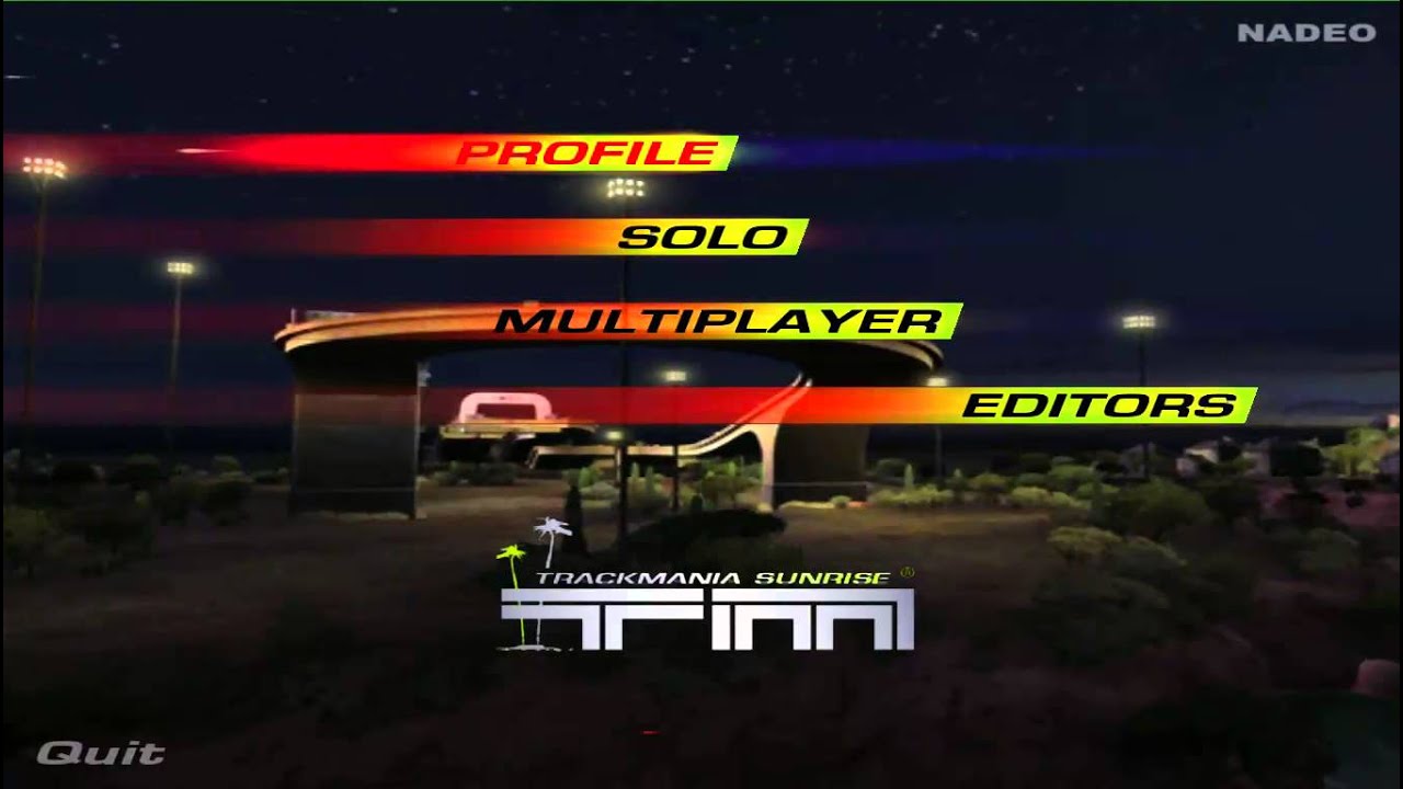
Another Main Menu Themes:
https://www.youtube.com/playlist?list=PLo2f0DnBXQZX7OUoXdjIRjHj7mJwp0LnU
Main Menu Theme from TrackMania Sunrise.
anything that would cause unity_InstanceID to not be set in a shader graph lit material? Im using Graphics.DrawMeshInstanced
it works about half the time
if I dont access instanceID at all, there's no error but obv not what i want
Thanks. So I just drag that shader to any material which is on the plane? Sorry I am a bit beginner
I dragged it on Plane's material and it is hidden now but not hide anything
im making shaders intended to be applied to spheres. For some reason, they appear to by symmetrical along the middle of the sphere


like, the top and bottom half always look the same
That's because the Gradient Noise is 2D and using the Position node as an input (top left of graph). The position node outputs a Vector3, but the Tiling And Offset is truncating it down to a Vector2. There may be ways to map it differently (e.g. using Arctangent2 & Arcsine) but not really without seams.
Using a 3D noise function would work, I know Remy's library has some. https://github.com/RemyUnity/sg-node-library
yooooo you can download custom nodes? i didnt know that was a thing
oh right, its called subgraphs right? ive seen those as menu options
Yeah they are subgraphs. But some likely just containing custom function nodes.
also, do i import this as a package or just download and put into my assets?
Either would work, but it looks like it is set up so that you can install via package manager (using https git url)
dope, thanks cyan
i tried the noise simplex 3d noise but the sphere is still symmetrical

The Tiling And Offset is still truncating as it's designed to work with UV coordinates. If you want to apply tiling values to the Position node, use a Multiply node, then for offset use an Add
gotcha, ill try to impliment that
hell yeah, looks beautiful now, thanks cyan!

where can i find more subgraph packs like remys?
Can you create a wall cutout shader where you don't have to paste the shader code over every wall? I want the player visible through walls.
Is there any reasons why scrolling a noise texture by offsetting it with time would not be working in a vertex displacement shader ? The noise scale directly affect the displacement, but there is absolutely no scrolling happening. yet in the shader graph preview I can see it scrolling properly.
show your code?
Just started to really try and learn shaders, I've got a vertex shader working and now I want to make a nice fragment shader.
How do I access the depth buffer/texture from a fragment shader? I've gone to many websites and I cannot seem to find a working solution
you don't manage the depth buffer afaik
just utilize ZTest if you want to change how you compare against the depth buffer
Nevermind, figured it out! Just had to pass a variable to COMPUTE_EYEDEPTH
can you use a scriptable render pipeline that doesn't make textures go pink?
You have to use shaders that are compatible with whatever RP you're using or you get pink
so if i code a shader and say what the frag and vert functions do then it won't work with URP?
If I use a scriptable render pipeline, can I make a stencil buffer where all objects have a cutout hole in them to show the player?
probably?
i want to avoid using the same shader code on all environment objects
i.e. dragging and dropping the shader code on all those environment game objects
i'm not familiar with shaders and pipelines 100% yet
Hi, I'm trying to make a shader with shadergraph and I wonder if it's possible to get world space normals using the depth texture of the camera. I know I could use the normal node in shadergraph but it has bad performance since I want to apply the material to all of the scene. So I put a plane on front of the camera. Is it possible like the world space positions? https://docs.unity3d.com/Packages/com.unity.render-pipelines.universal@13.1/manual/writing-shaders-urp-reconstruct-world-position.html
SHould be possible. Follow the same approach as in that article - just with graph nodes instead of code
e.g. to sample the depth texture use https://docs.unity3d.com/Packages/com.unity.shadergraph@6.9/manual/Scene-Depth-Node.html ?
(i think)
how can i know what shaders are compatibile with what pipelines?
Like what pipelines is this shader code compatible with? https://forum.unity.com/threads/only-draw-when-behind-object-shader-computation-complexity.1249096/
Unity Forum
How can you make a shader only draw when the object behind another object, is it possible? I want an x-ray shader effect.
So far I already have...
I really have no ideas how to get normals... the positions are like this

I imagine you'd have to get a bunch of neighboring world space positions (maybe the surrounding 8 pixels) and do some interesting math?
not really sure
I think anything with CGPROGRAM is the builtin renderer. I think all the URP stuff is HLSL?
they look so similar
Yeah... I found this but I don't understand xd

it's... not simple stuff 😛
it's linear algebra, you need to calculate the inverse of a matrix
I don't understand either
I guess I was right about the neighboring offsets thing but that's about as far as I get 😛
a matrix provides linear transformation for your inputs, kind of like a filter
get the projection view matrix, then calculate the inverse of it
Oof... All of this to make my caustics work with the sun angle...

in shader graph?
i don't use it, wouldn't know but i don't see why not it wouldn't have it
you could calculate manually if you wanted to if there's no inverse function
https://www.cuemath.com/algebra/inverse-of-a-matrix/
there's definitely a matrix inverse in ShaderGraph
The thing is that I don't know what's a matrix lol

a matrix is a grid of numbers you can see them as
but it's actually a collection of vectors you can say
ahhh so it's the neighboring points?
no it's like a formula to transform things
but the 4 inputs are the points?
kind of like applying quadratic formula on quadratic functions gives you roots
I'm good in maths but only in my class
idk
ok so
the 4 inputs is your xyzw I think
what's w 😭
it's a 4th dimension i think because of quaternions
because limitations to 3D geometry rotation, gimbal lock
makes things less buggy
I don't understand quaternion but which rotations do I pass to the matrix?

you need to grab the projection view matrix, is that not already a node?
hmm wait

InverseViewProjection
yes
?
i'm guessing you would want to apply the matrix on each vector
like a pixel's location, i.e. it's vector xyzw
then that would give the normal you're probably looking for that vector
so the xyzw output is like the normal
otherwise look at the example shader code linked
yeah i think as i'm guessing what you're doing and what needs to be done
Material.SetMatrix("_LeftWorldFromView", left_world_from_view);
Material.SetMatrix("_LeftViewFromScreen", left_view_from_screen);
apparently you need to set your view's matrix
is it possible in shader graph
i don't know, i never used shader graphs
ah you seem to be good
As you can see i'm bad

i was wrong, xyzw isn't quaternion based, it's a homogeneous coordinate system
So do I have the correct start or...
don't know
ppl have nice scripts https://forum.unity.com/threads/world-normal-from-scene-depth.1063625/
?

I would like to make shader for a plane in Unity which can hides everything behind it in Game view
Anyone can help?
Like I proposed earlier, here is a shader that you can apply to your plane.
Shader "Unlit/DepthMask"
{
    Properties
    {
    }
    SubShader
    {
        Tags { "RenderType"="Opaque" "Queue"="Geometry-1"}
        LOD 100
        ColorMask 0
        ZWrite On

        Pass
        {
            CGPROGRAM
            #pragma vertex vert
            #pragma fragment frag

            #include "UnityCG.cginc"

            struct appdata
            {
                float4 vertex : POSITION;
            };

            struct v2f
            {
                float4 vertex : SV_POSITION;
            };

            v2f vert (appdata v)
            {
                v2f o;
                o.vertex = UnityObjectToClipPos(v.vertex);
                return o;
            }

            fixed4 frag (v2f i) : SV_Target
            {
                return fixed4(1,1,1,1);
            }
            ENDCG
        }
    }
}

So I should make a new shader and copy there this code?
Yes
Amazing! Thanks
hello. im trying to make a shader graph for hdrp, and i cant get teh alpha clipping to work.
i setup a slider property and attached it to the alpha clipping. but when i move teh slider nothing happens.

Remy can you help me with this situation?
I have a model which has tentacles with cool animation. I would like to cut down just one tentacle but keep the animation but the model is not splitted into several parts so I need to cut down it in an external modeling software. How can I do that but I can keep the animation?
Where is the alpha value comming from ? It's not clear from the screenshot
The key here is to keep the vertex weights data for the animation I guess.
A easy solution would be, in the modeling software, to dupplicate the mesh, on the original one remove the tentacle, and on the copy remove the rest bu keep the tentacle :).
This is maybe more a question for #🔀┃art-asset-workflow or #🏃┃animation btw
the alpha itself was supposed to be a fade, where if the player goes under the tree it fades away. so you can still see the player. its an isometric top down type game.
for some reason in HDRP i cant just change the alpha in code in order to make the leaves fade away and then back in once the player leaves.
so im trying to make a shader that can do it.
Alpha clipping is a simple (alpha > clip value)? comparison.
Could it be that the alpha value is always higher than the clip threshold value you set ?
well the original shader that came with the tree asset works just fine with an alpha clip value of 0.5
original material*
does the texture 2d also need to be attached to the alpha slot?
But with that I lose the animation on the tentacle 😮
Yes, as I guess that the texture alpha channel was used to provide informations to draw the leaves shape.
yeah im a total noob and i couldnt yield any google search results on the top of alpha clipping
You shouldn't.
Take time to learn on how to use your modeling software to do that.
i just googled a tutorial on how to do a fade effect when the player walks near an object.
and tried to add the texture to it.

Are you sure of what you're doing here ? 😅
From what I understood, you wand to hide the leaves in a circle around the player, right ?
Offset beeing the player's position, in screen space ?
Hum, no, offset is a float value, so I don't get what it's used for
i am not sure at all. this is my very first attempt at making a shader graph ever
idk either. i just watched a tutorial and he had an offset.
the range is supposed to be the players range from the game object
but y eah the plan is, when the player gets close enough to the tree. the leaves should fade out as to not block the camera
i just watched a tutorial and he had an offset.
Is this tutorial supposed to do what you want to achieve ? If yes, and you don't have the same result, you probably missed some stuffs
wellt he problem was with the video he wasnt using any texture
it was just a low poly game object with a solid color on it.
so i just copy what he did, and now im tryign to add a texture.
but the texture has this alpha clipping, which idk how that works at all.
If the texture is the only issue, you just have to multiply the texture sample alpha value to your alpha before the stack alpha input.
ok so just add a multiply node and combine them both togther?
sweet that worked
thanks a ton
but yeah the distance check doesnt seem to be working, because i think it checks the camera distance? is there a way to maybe add a collider to the tree, and when the player hits the collider it triggers an alpha change on the shader?
i see there is a boolean property. is it possible to hit that with code?
Everything is possible with more or less effort, but if the effect was working in the tutorial, it should also work on your side, unless you missed something.
For example, I see that you used the alpha value of the screen position, which doesn't make sense to me
yeah, idk what the "screen position" even is.
i can only assume that it checks the screen position of the game object in relation to the camera.
which wouldnt work with an isometric game since the camera is so high in the sky.
i need to use the players position.
It's not an event.
The screen position is "the position on the screen of the current pixel"
yeah, if i could just trigger the change in alpha value with code. with an ontriggerEnter and ontriggerexit.
flip that bool to trigger the fade.
that would prolly be better.
As you wish. Like I've already said, if it worked in the tutorial but not in you project, you probably missed something, the texture alpha beeing a detail here.
if i make a property like a bool, how do i access it in code?
meshrenderer.materials[1].(nameofbool)?
You can use https://docs.unity3d.com/ScriptReference/Material.SetFloat.html with the bool reference name and 0/1.
Internally, material booleans are just floats
ah i see. i hope this works. i tried using SetColor() and it would change the alpha, but ontriggerexit, it wouldnt SetColor() again back to 1f.
Is there a shader like the built-in Particle/Standard Unlit, except it also does light/shadow like Toon/Lit?
quick noob question, hope this is an ok place to ask: when I look at a normal map, it is mostly shades of purple, ie varying values for X and Z and not so much in Y. Why is this? I assume the values are in tangent space, so they're relative to the existing normals, so I guess it doesn't make sense to be spinning a normal on the spot? Is that about right?
Values in a normal map are not rotations, but a 3D directional vector coodinates, ranging from -1 to 1 in all axes.
As we can't represent negative values with colors, 0 is -1, 128 is 0 and 255 is 1.
Normals are mostly used in tangent space mapping, where the Z axis is pointing "away" from the polygon you are looking at.
So, put all this together, and a normal without perturbation, aka no changing the face normal value, is a vector of (0,0,1), converted to rgb : 128, 128, 255 => a light blue.
This explains why most of the color you see are shades of this, as it's not very often that you will see things pointing parallel to the surface, like let say, (1,0,0) which would be pure red.
@amber saffron ah, that really helps, thank you!
wait, wouldn't (1, 0, 0) be (255, 128, 128) which would be pink?
in fact values less than 128 would be really rare since they would mean that the normal would be "inside out" so to speak, right?
How can I make the textures nontransparent in unity, I have’n problems in blender?


Maybe its transparent only from one side?
Hah, yes, error on me.
Values below 128 are totally expected for the red and green channel, way less for the blue one.
There is also "object space" normal maps, where the vector value is ... well, in object space, and not tangent, in that case the full range of values is used, including negative values for Z
ah yes, I just did that with pointing fingers and I see what you mean. It would only be blue that if negative would be weird.
how can i assign a color to my alpha and to make the black greenish and semi-transparent ?

Remap the alpha before the combine so that the lowest value is like 0.2
If this goes into the master node, you can just connect the Color property to the Base Color port, and one of the float channels for the Alpha port. It's usually easier to keep the color/rgb and alpha parts of the graph separate.
(Optionally also split the Color property, take the A output (or using a Swizzle node with "a"), and multiply before connecting to the alpha port - if you want the property to still affect the transparency too)
Thanks a lot for the answers got it working !
There are more uavs (9) than the maximum supported (8) in ComputeShader 'RayTracingShader' kernel 'kernel_shade'.
D:
I thought it was 12
is there a way to set a buffer as read/write for one kernel and as read only for another kernel in the same compute shader?
Hey does anyone know how to turn off backface culling on a shader? I don't see the option on the standard shader
hey why does the camera normal texture change as you move? what transform is needed to have that not happen?
Cull Off
SubShader {
        Blend One One
        Tags { "RenderType"="Transparent" "Queue"="Transparent" }
        LOD 200

        ZWrite Off

        UsePass "Custom/Depth Fade/DepthCharge"

    }
I'm trying to use a pass from another shader, but have it use an additive blending instead of a basic transparency. But even tho the "Blend SrcAlpha OneMinusSrcAlpha" is outside of that shader's pass, it still won't override. Can someone help?
hey guys, pretty new to compute shaders, but i need to use them as advised by one of my professors for my project to speed up execution times
im really struggling to get this working, and the key thing ive put it down to for now is that im not reading the pixels of a texture correctly
i have the RWTexture2D<float4>, i set the texture in C#, but then i cant read invididual pixels of the RWTexture2D in the computer shader itself according to the ID of the kernel function, i've tried both a direct access with the index id.xy and I've tried passing id.xy into a call of Load() on the RWTexture2D, but no luck
any help?
Update: troving back through this server I'm hearing that for INPUT textures to a compute shader you wanna use Texture2D<float4> rather than RWTexture2D<float4>, i'm trying that now but no change so far
What have you set numthreads to in the shader and the number threads in the Dispatch call?
hold on, lemme get that info for you
my numthreads is set to 8,8,1 and in the dispatch call its:
Mathf.RoundToInt( (float)levelPlan_asRT.width / (float)numthreads_X),Mathf.RoundToInt( (float)levelPlan_asRT.height /(float) numthreads_Y), numthreads_Z
with numthreads_X, _Y, and _Z being the same as numthreads in the compute shader respectively
i do the mathf.roudntoint thing because im unsure how integer division errors happen tbh so i do float division and round the result to int to be safe
That looks correct. How are you determining that the shader isn't reading the pixels correctly?
okay, so what im doing is im reading in each pixel in the compute shader, and simply sending that pixel back out into a different structured buffer related to my project
when i read that pixel which hasnt been modified at all in the compute shader, read together with all other pixels, i get an image the same size as the input image but it is entirely light grey, 0.8,0.8,0.8 RGB to be specific
on top is the image im reading and on bottom is what i get


theres more going on in my main kernal function but right now the only data im actually USING in C# is the original pixel colour, it should produce an identical image
You could try writing a fixed, hardcoded color in the shader instead. If you see that color, that pretty much confirms it's the read of the original texture that is the problem.
well that would detect it but i dont understand how that would solve it, maybe im just misunderstanding
i SHOULD note that when i went through the effort to pass in the texture2d instead as a buffer of float3 values, it read the image kind of fine, it just came out greyscale?
like what i mean is instead of using Texture2d<float4> i was using RWBuffer<float3>
I'm not proposing a solution yet, just debugging to confirm where the problem is.
ah okie gotcha
so what youre saying is, to debug this, instead of trying to access the textures pixels, i take that line and access a hardcoded colour, and if it still comes out grey then we know more as to the cause?
Yes, or wherever you're writing the texture pixel color to the structured buffer, write a hardcoded color instead.
gotcha, lemme try that and see what happens
alright, i hardcoded the input pixel colour to pure black, and i got a pure black image, so it is the reading that is the issue

Alright, thanks for testing that. In that case, what texture format is the original texture in? And is it a RenderTexture?
the original texture has this for formatting, and it WAS a rendertexture a few hours ago, i could try turning it back into a rendertexture for you now if youd like, the code to make it a rendertexture with enablerandomwrite but still looking like the sourcetexture2d is still in my source, i just need to uncomment it

i tried to post my code for the texture2d to rendertexture thing i mentioned but it got auto deleted fsr :S
ALSO, important, up until now ive been resizing the image in c# before all of this using a more basic version of point filterting i programmed which creates a new Texture2D and does not modify ANY of its formatting, so that could be a problem? i potentially have been going into this function with a Texture2D on totally default formatting unlike the one in the image i posted just now
Are you calling .Apply() after resizing the texture?
yeah, you see the function im running with this computeshader is just a straight conversion from C# to HLSL of a function i already had working, this all works perfectly if i go back to my old function for reading the image
im accessing the pixel of the input image in my compute shader currently with the line:
float4 col_full = levelPlan[id.xy];
and the image is put into the compute shader constants as the buffer type Texture2D<float4>
just to clarify since i did a lot of tweaking about at the start as mentioned
Would you mind uploading the compute shader and script to somewhere like https://hatebin.com/, so I can see the whole picture?
yeah sure, itll be amateur as all hell but you can expect that from a newbie like me of course
alright heres your pastes:
https://pastebin.com/2cm10WM2 for the compute shader
https://pastebin.com/NMUgN4MG for the largely relevant c# side of things
Pastebin
Pastebin.com is the number one paste tool since 2002. Pastebin is a website where you can store text online for a set period of time.
Pastebin
Pastebin.com is the number one paste tool since 2002. Pastebin is a website where you can store text online for a set period of time.
sorry if some of this seems nonsense, its contextual within the project, but i can explain anything that seems nonsense from my point of view
of course some of it might ACTUALLY be nonsense given my newbie status with HLSL
oh yes, and this line towards the end of the second paste, im only setting it to the original colour of the image so that i can get a direct copy output through printing the colour set to determine the source of this grey issue
@tiny star Could you post the Texture2DToRenderTexture method as well? According to this paste, you are converting to a RenderTexture currently.
oh yeah, i changed that for you preemptive of a request to do so, sorry, ill get that for you now
https://pastebin.com/Dw3dkLFV here ya go!
Pastebin
Pastebin.com is the number one paste tool since 2002. Pastebin is a website where you can store text online for a set period of time.
And to confirm, the Texture2D levelPlan being passed into the LevelPlanToColourSet_ComputeShader method is an unmodified texture asset in Unity? Or are you still resizing it manually?
it is unmodified when passed into the function, completely as is from the files
all modification on the texture up until that point begins and ends in that function
@tiny star It's difficult to say what the problem could be when there's so much going on. You can at least do some debugging to confirm the inputs given to the shader are as expected by using a GPU debugging tool like RenderDoc, which Unity has built-in support for.
hmm, okay then, well thanks for taking such a deep dive anyway, ill look into renderdoc and if i come up with anything interesting ill let you know
@tiny star
What's this line supposed to be doing in the compute shader?
colSet_2dAs1d[(id.y * lvlPlan_dimensionX) + id.x] = iterationResult;
It looks like it is setting the struct in the destination RWSB. So, that's where I'd start looking, entry by entry.
Fog wont show up in the build but it shows up in the editor. These are the settings for the fog.


Which editor version?
Hello guys, I'm newbwee on this server
I'm 1.5 years experience unity game developer. So now, i want to start learning hand-written hlsl shaders. So basically i have 2 questions
- is there any possibility to install intelisence HLSL for rider?
- is this correct channel to ask dumb questions about HLSL scripts?
Rider Unity plugin adds support for HLSL and ShaderLab. There's some intellisense. This is the right place to ask questions about shaders in Unity.
Hi, I'm trying to make a custom function in shader graph and my hlsl script in like that. I have an error and I really don't know how to fix it. I know nothing about shaders so someone can tell me what to add in my script? or where is the error?

What do I need to #include?
It looks like you've set the precision of the Custom Function node to Half (maybe set to "Inherit" by default), so it's looking for the function named "WorldNormals_half", rather than "WorldNormals_float". You should be able to change the precision in the Node Settings. Or rename / duplicate the function with the appropriate precision.
This ?

Ah ok

It's already on Inherit...
When I change it it says this
Then perhaps it's inputs are using half precision (meaning the custom function would inherit that same precision. Can just use "Single" to override it to float-only if that's what you want.). If it's in a subgraph then Switchable probably means it needs both float and half versions of the function defined to work. That's pretty new so not that familiar with it. https://docs.unity3d.com/Packages/com.unity.shadergraph@13.1/manual/Precision-Modes.html
Ok so I recreated the function and now it says this

"WorldNor_5' used without having been completely initialized at line 297 (on d3d11)"
I tried to set single but it makes me this error now
That's good, it means the precision is no longer the problem. That new error might be because you haven't specified it as an out parameter. Try out float3 WorldNor in the function params.
Do you know how to convert an unlit shader to a custom function in shader graph?
Hi I'm using draw mesh instanced indirect, using the example from https://toqoz.fyi/thousands-of-meshes.html, but when I try to add another variable to the "MeshProperties" class that goes into the buffer it all looks blue for some reason. The only things I changed are: Adding a float to the MeshProperties class in the C# script, adding another SizeOf(float) to the size function in the MeshProperties class in the C# script, and adding a float to the MeshProperties class in the shader.
Before

after

Do i need to add something to the compute shader?
if i add the extra variable to the compute shader it gives me this error
Assertion failed on expression: 'index >= 0 && index < paramArray.size()'
thats when i call compute.Dispatch(kernel, Mathf.CeilToInt(population / 64f), 1, 1);
it also (sometimes) shows this Compute shader (NewComputeShader): Property (_Properties) at kernel index (0) is not set
where is that option? as I said I don't see any option to do it.
Its not an option on editor but part of the shader code. You can write it in top of subshader or pass
oh i see so like in the actual text?
Yes
Ah okok makes sence
Urp (and maybe hdrp) lit shader should have double sided option already
I don't have the project open right now but I am very sure I know how to do that
I forget if I am using urp for that project cause I have so many projects
but yeah thanks mate
Standard shader on built-in render pipeline doesn’t have that checkbox on it
Doesn’t matter. Both birp and urp can have double sided shaders but on birp you have to manually add the Cull Off for the shader code
I mean urps lit shader (don’t know about hdrp) has this option on it

hey, how do I create an array of something? I'm trying to create an array of float3's in my shader that I'll set using a script but I just keep getting errors. as usual, google is not being very helpful
i tried float3[3] _floatArray; but it didn't work. let me get the exact error message...
"Hidden/FirstIEShader shader is not supported on this GPU (none of subshaders/fallbacks are suitable)"
(my shader's name is FirstIEShader)
float3 _floatArray[3];
oh gosh, thank you!
hey my shaders are streching out at the end of the texture and i dunno why ;-;

im not very experienced with shader graphs
@half oysterIt comes from texture sampling, and you MAY be able to ignore it. IDK what your inputs are for the UV or the use-case on an actual model, but you can try messing with the sampler state by creating a sampler state node and plugging that into the SS link on your sample texture 2d node. Like change the wrap mode or filter mode. Also check the range of your UV results.
alright so i plugged sampler state node into the sample texture 2d thing and it changed nothing. also i have no idea what UV results mean.. I was just following a tutorial for brackeys 2d glow stuff. Heres another photo with the sampler state

Did you change the wrap mode ?
yes i changed the wrap mode to all the other types
OK, you can probably just ignore it as an artifact.
What I mean by "UV results" is if the UV values go below 0 or above 1.0 in range.
But on your latest pic, you show that you're using UV0 as a direct input, not a calc.
Hi people of the cord,
I am once again asking for shader advice.
I downloaded some Gerstner waves by Zicore. When adding a terrain, it doesn't blend well into it. I saw a couple of other tutorials implementing a way to make the water more transparent as it gets near land. ping me if you have experience with this. Thanks

Does anybody know why my water is jittery?

By artifact you mean the thing were it streches out right? If so the streched out thing is still in-game.
OK, check the import settings on the texture. Also the texture type.
ok i changed the texture type to default now its like this (also i added the other glow stuff)

looks like it is gone
but i can no longer apply the texture to things
You mean "the material"?
the texture
IDK what you mean.
If you take the material that uses this new shader, and put it on a sprite....that's how you apply "the texture".
What do you mean you can't apply it? Do you get an error? Or a hot-pink result, or what?
I changed the texture to default here and it fixed the issue inside the shader. But since my object was a sprite i could no longer apply the texture to it.


I don't do 2D much, so someone else will have to comment. I'd assume PhysgunMaterial would have the texture mapping in it. Or if it won't let you assign it, that you can keep sprite import texture type, but change the advance wrap mode to something else.
ok thanks for the help
You probably:
- didn't adjust the size() function for the struct properly
- didn't adjust the shader version of the struct to match your C# change
Something like that
im 90 percent shore i did both of those things right EDIT: sry this was overly un accepting I've been talking in a politics discord XD
i didn't change it in the compute shader though but I've tried that too and it didn't work
If you didn't change it in the Shader then your buffer will be all misaligned
Leading to stuff like that wrong color
it is changed in compute now though with the same results
If you changed the struct, did you also remember to change the stride?
probably not because i dont know what that is
Basically, sizeof(struct-name).
oh, yea
¯_(ツ)_/¯
private struct MeshProperties
    {
        public Matrix4x4 mat;

        public Vector4 color;
        public float tex;

        public static int Size()
        {
            return
                sizeof(float) * 4 * 4 + // matrix;
                sizeof(float) * 4 // color;
                +sizeof(float) ;

        }
}```I like that. So you use the MeshProperties.size() when creating the compute buffer.
Uh, you swapped the order of tex and color there.
that matters??!?!!?