#archived-shaders
1 messages · Page 228 of 1
Look up Triplanar shaders
Hello, is the cost of Rendering a mesh with scale of zero the same as its renderer being disabled?
Does anyone know the URP equivalent of "UNITY_INITIALIZE_VERTEX_OUTPUT_STEREO()"?
ah wait nvm its still the same
ok thank you
https://www.youtube.com/watch?v=lUmRJRrZfGc&t in the description of this video there is a download for the shader this guy made and when i open the project in unity it works fine but when i try to use it in my project its just pink

Tons of games use a stylised cel-shading art style to help them stand out graphically, including hits like Zelda: Breath of the Wild, Persona 5 and Okami. In this tutorial, we'll unlock the secrets of cel-shading in Shader Graph by using our own custom lighting and end up with an effect that supports multiple lights!
👇 Download the ...
Does anyone know why when I change my players material it goes all weird? This is what it looks like normally.

But when I put a custom shader material on it it looks like this

For some reason the sprite looks weird in the shader as well

your shader is not setting the alpha value. Try just dragging your output into the alpha node (in addition to the base color node)
@wraith inlet It ended up looking like this
And you can still see the texture is stretching for some reason, like the sprites outline is stretching out

You can't just drag a Vector4 into the alpha (a Vector1) or it'll take the first/red channel. You need to use a Split node first. Then use the A output.
May also want to Saturate to prevent the alpha being out of the 0-1 range which may affect blending.
I ended up doing this that stopped the weird texture wrapping

But the player still has this black box around it

@regal stagDont know why it works now but it does

shouldn't you get the alpha from here? (use split node to get the alpha)


well, did you use split node or just connected it to alpha node? If you just connect float4 into float, it just uses the first element (red channel) of it and ignores others
Hi, I'd like to use the color/histogram from a rendertexture (camera rendering to a rendertexture) to impact another gameobject. Trying to understand the GPU and CPU of things as well as shaders and gfx programming. Is this roughly the approach I'd use? (with further processing of course) https://docs.unity3d.com/ScriptReference/Texture2D.ReadPixels.html

I am using HDRP. And the Video Player to output to a RenderTexture.
Got it working.
Is step using if-else statement internally? I'm trying to clean up a draft shader and get rid of all branches but some people say step is good, others say not to use it
And I'm not a shader expert to know better
No it is not. The whole idea of step is to avoid branches.
That's great to hear
Does it also mean I can use >= too?
Since it seems to compile down to it anyway
>= is a simple boolean logic operation, it doesn't have any branches
if and for etc introduce branches
yes, implicit in a for loop is a branch for when to exit the loop
This is a somewhat complicated subject and you've more or less reached the limit of my understanding.
I guess just refactor it to the point of not needing a loop 🤷♂️
Just did a quick search and it pretty much says this
if possible, that would probably be ideal, yes.
Aight thanks
Oh also one more question
So I read up that geometry shaders have terrible performance
So if I needed to discard a vertex, would it be better to just set it's position to NaN in vertex shader rather than include a geometry?
Also how about clip? When i googled it, they told its same as ´if (x < 0) {discard;}´ (in terms of performance) but is it?
Shader programming be wild
Does shadergraph have a Get Normal from height alternative for the vertex shader @regal stag ?
Nope. The node relies on ddx/ddy which can only be used in the fragment stage. For vertex you'd have to calculate it yourself. There's a method explained in this post that might help (https://www.ronja-tutorials.com/post/015-wobble-displacement/), but it's *3 the cost
ok, thanks!
Hey im trying to follow this tutorial to make a lava shader: https://www.youtube.com/watch?v=w7qDzz5K8Gg&list=WL&index=27&t=65s&ab_channel=REM118

MY PATREON: https://www.patreon.com/rem118
Графический планшет XP-Pen Deco Pro M: http://ali.pub/57blhv
Графический планшет GAOMON PD2200 21,5 дюйма: http://ali.pub/57fckx
Интерактивный дисплей XP-PEN Artist 22E Pro: https://ya.cc/DpPLM
but for some reason, the time node doesnt work the same way for me as it is in the video
If i just connect time, the material becomes blank and stays static. The only way i can get the flowing effect is by using sine time
I feel since the image the time node is being applied to is not infinite the time keeps increasing and the end of the image is already reached thats why it looks blank but how could i make it endless?
The texture they use is probably using the Repeat wrap mode while yours might be set to Clamp instead. (Referring to the texture's import settings, not in shader graph, though you could also override it by connecting a Sampler State to the Sample Texture 2D)
This is so weird.
The docs say CommandBuffer.Blit should set _MainTex.
But on 2021.1 it sets _SourceTex instead.
I literally accidentally stumbled upon the correct texture name.
I think I'm going to not trust it and use my own property name for blit sources from now on.
which renderer?
URP.
then the recommended way is to avoid cmd.blit
I don't care about VR tho. Never gonna support it.
yeah but Unity made a stance recently that even without VR, you shouldn't really use cmd.blit anymore
"CommandBuffer.Blit is the legacy way to blit in Unity and should not be used."
Also they literally provide a Blit method on the ScriptableRenderPass.
Hmm, a Blitter class. Let's see if I have that on my boomer 2021.1 Unity.
oh right, you can't use that there yet 😄
Yeah, I don't think 2021.2 is quite there yet, it gives me internal compiler errors.
that doc is for 2022.1, since it has same RTHandle setup as HDRP
I guess this explains why they still keep pushing that cmd.drawmesh approach on current URPs
so... the only takeaway from all this is... it's a mess right now
cmd.blit works if you don't need vr but is not recommended, cmd.drawmesh works for all purposes but it requires extra boilerplate code, new srp blitter only works on bleeding edge
so... I guess use whatever works now and reconsider when Unity 2022 is relevant
From what I peeked in the sourcecode, doing blitting with a quad is like 3 command buffer commands.
if you use opaquetexture, it can be done with single command, depending what you want from it
Well, I tried doing alpha blending in post processing...
And that boi ain't working right.
So I assume not doing opaque post processing is invalid.
Well, I guess the background texture wasn't bound.
Hey, i'm trying to make an object turn into a different color when hovering over it. Which works fine, however when i have multiple objects with the same material, they all turn blue, is there any way to fix this?
I'm using the shadergraph in unity 2019.4.32f1
@left monolithonly change the properties for that specific material instance? I'm guessing you are now trying to change the color through some global setter?
    Material material;

    // Start is called before the first frame update
    void Start()
    {
        material = GetComponent<Renderer>().material;
    }

    private void OnMouseEnter()
    {
        material.SetInt("isHover",1);
    }

    private void OnMouseExit()
    {
        material.SetInt("isHover", 0);
    }
this is how i did it, is the renderer.material a global one?
no
what happens then?
huh
¯_(ツ)_/¯
also in shader graph?


don't mind that, it's just newer URP version (tried it on Unity 2020.3)
Is your boolean property set to be exposed?
does it need to be?
i'm only using it through code
i tried it and yes, that's the problem
yup
If you are setting via material then yes. If you don't have it exposed, SG treats it as a global variable and it should only be set through Shader.SetGlobalX, otherwise you get problems like you are encountering due to batching.
kinda annoying that those are connected

It kinda needs to be exposed in the Properties block to work correctly with SRP-batching
ergh
If you override it like that, it'll break the SRP batcher compatibility
welp, ugly editor it is
ah
(Though, for matrices it's a bit different since they can't be exposed, but SG still treats those as per-material. If you try setting it with Shader.SetGlobalMatrix you actually need to use the override to Global or it just returns seemingly garbage values)
Anybody know how to make 3d wobbly sketch outlines like in Life is Strange?
This is a good list of different outline techniques : https://alexanderameye.github.io/notes/rendering-outlines/
I am familiar with most of em. This case is very particular: I essentially have to run the outline in a screenspace shader but make it so it looks like the outline is a mesh in world space.
Not sure which is best for replicating that in particular but if you can get the outline in a separate buffer you could then blit it to the main camera while applying some distortion/noise when sampling to make it wobbly. And offset that distortion by floor(time) to make it jump rather than scroll.
Can also use that buffer to mask the inner parts of the object with a screenspace texture filled with the diagonal lines.
So occluded by depth, wobbling in 3d..
Yeah, the distortion I already came up with. But it's the ughh making it back into worldspace I have no idea about.
So it wouldn't be constant width in screenspace.
Not sure if it's how LiS works.
forgive my lack of knowledge on shadergraph (and shaders in general), but I'm trying to make a shader that applies a texture based off of the light level on an object, I already have the lighting calculation stuff worked out, I just don't know how to make the texture change depending on it.
Here's the lighting:

And here's the texture I want to apply
like the furthest left tile in well lit environments, and the rightmost tile for the darkest environments
any help would be appreciated
Multiply the texture with values of certain range
I think you have to use the step node but im not sure
I'd probably combine the texture into a single square gradient texture (see below). Can then do something similar to this, assuming the dither is meant to be in screen space. There's also a Dither node which you could use as an alternative (though it's a different pattern)

This is the texture being used (with import settings : Repeat wrap mode, Point filter mode, no compression, mipmaps disabled)
struct VertexInput {
   float4 vertex : POSITION;
   };

struct v2f {
   float4 pos : SV_POSITION;
   float3 worldPos : TEXCOORD2;
   };

v2f vert(VertexInput v) {
    v2f o;

    o.pos = UnityObjectToClipPos(v.vertex);
    o.worldPos = mul(unity_ObjectToWorld, v.vertex);

    return o;
    }
If I do this, will worldPos contain the real Z value of the object, or will the TEXCOORD2 designation mess up the values somehow?
Should be fine. TEXCOORDn doesn't change anything, they are just interpolators used to pass values. As long as it's float3 it'll pass the z value.
Thank you, helpful as always @regal stag 🙏
Heyas,
I'm trying to add a dissolve effect to an existing shader (I have very little shader experience). I found a tutorial online (https://www.febucci.com/2018/09/dissolve-shader/), which asks me to add (among 2 properties):
    half dissolve_value = tex2D(_DissolveTexture, IN.uv_MainTex).r;
    clip(dissolve_value - _Amount);

    //Your shader body, you can set the Albedo etc.
    //[...]
}```
Now I managed to figure out that this is for a Surface shader, whereas the shader I'm trying to edit is a fragment shader. The frag function on the shader looks like this:
``` half4 frag ( VertexOutput IN , half ase_vface : VFACE ) : SV_Target {
    // Lots of magical shader gibberish
} ```
The error I'm getting is 'tex2D': no matching 2 parameter intrinsic function'; which I'm guessing is a result of the IN variable being of different types in the surface and fragment shaders? Any clues how to fix this (or if I'm even remotely in the right direction)?Is it possible to do vertex manipulation of an object in a shader, but have it be independent of other shaders?
So i could still use PBR material
Not really. The vertex and fragment shaders are always linked and used together. You can still manipulate vertices in a lit shader though. If you're in the built-in pipeline you probably want to look into using the vertex:functionName compilation directive for a surface shader. There's a few examples on this page ; https://docs.unity3d.com/Manual/SL-SurfaceShaderExamples.html (though with Lambert instead of Standard but it would work for any lighting model)
So I have two objects with sprite renderers, and they both have the same texture attached, but when i move them both to the same "order in layer" they both break and the shader no longer does what it's meant to do.
Yet when I keep them on the same order in layer, but switch the texture to something unused, they both start working again.
I assumed this was a batching error, but both static and dynamic batching is turned off. Is this something specific to the sprite renderer that's breaking my shader with how the order works or something?
I'll look into that. Thanks!
Also reading the unity shader 2021 cookbook so stuff should become more clear soon.
I think there is a special sprite-batching thing even without using static & dynamic batching, though I could be wrong (I don't use sprites a lot). The frame debugger window would probably tell you if it's being batched or not.
well i guess you learn something every day 😩 ill try to check this frame debugger otherwise i guess ill just have to switch to meshes
The type of IN isn't important for the tex2D function, it just needs to contain the UV coordinates. Hopefully the VertexOutput struct already contains them, but if not you'll need to add them first by using an unused TEXCOORDn channel, e.g. (float2 uv : TEXCOORD2). Also the same but using TEXCOORD0 in the VertexInput. Can then pass the variable through in the vertex shader (OUT.uv = IN.uv).
Make sure you also have the sampler2D _DissolveTexture; before the frag function to define the texture itself.
Then you should be able to use tex2D(_DissolveTexture, IN.uv).r
Out of curiosity what part of the shader breaks? Is it something relying on the model matrix?
@regal stag i am writing my own 2D renderer so it's kind of hard to explain without showing all the code. but i have one large mesh where i am reading off a 3D texture to render tiles, and i have some doors as objects that are meant to be inside a building rendered on the big mesh, and hidden behind a wall, but when they are both put on the same sorting order they both become visible. i'm not sure if it has to do with the raycasting loop i am using, or if it has something to do with other variables being shared or something. but something breaks due to the sprite batching.
Hm okay sounds complicated
Managed to get it to work with that; thank you very much!
yeah it is lol 😄
can i have different _MainTex's on meshes somehow, on a shared material? Via the sprite renderer they all have separate ones but I can't just add a texture to the mesh renderer?
is this where it all falls apart lmao
I guess you could combine the textures into an atlas and use UV coordinates on the mesh to tell which part should be shown. Not sure if I'm understanding the problem correctly though
well, currently i am using sprite renderers with my own custom shader attached, and simply adding an image to the sprite renderer will set that as the _MainTex for the object, but they are all still using a shared material.
but with a mesh renderer i seem to be forced to add the texture to the shader itself which sets it globally on all objects
Oh right, sprite renderers probably instantiate materials behind the scenes and set the texture to use the sprite. You could do something similar in a C# script by setting the texture at runtime when using renderer.material (rather than renderer.sharedMaterial which would continue to be global)
wont that instantiate the materials though? or would setting the main texture only still keep them shared
im honestly not sure if it would be a problem if they would get instantiated hmm
They'd be instantiated yeah. I'm not sure if the same occurs with sprite renderers or if they use some atlas thing
the sprite renderer does not instantiate them. i think Unity like turns it all into one big atlas and keeps track of it internally or something? or so think i read. hoo boy this will be special to solve.
thanks though
Is depth something that should receive MSAA?
I am copying _CameraDepthTexture to a temporary depth target that has the same descriptor as the camera target and it starts erroring that bindMS on it is not set if MSAA is turned on.
URP.
I cannot open the shader graph, it only open in Visual Studio nor access to the Shader Graph Windows, but the package Shader Graph is imported, same for URP how do I force the shader to open in the shader graph window? There's no "open with" option or what
shader graph file is different from shader code file. you cannot open shader code file into shader graph.
This isnt shader?

where did you get that from?

Use the Enviro - Sky and Weather tool for your next project. Find this and more particle & effect tools on the Unity Asset Store.
that's shader but not shader graph. this is the shader graph icon
shader != shader graph. shader graphs are shaders too but you cannot open shader code on shader graph. this is what shader graph looks in inspector

weird af question here, but should i be learning shader graph or learn how to write shaders? or both? would writing shaders still be necessary in the future with shader graph existence?
If you're planning on using URP or HDRP, learn shader graph.
For now there's no examples or documentation for writing shaders for those pipelines outside of shader graph
If you want to use builtin render pipeline, you should learn writing shaders by hand.
ohh
i remember a page Cyan wrote about writing shaders in URP
how different is shader graph compared to writing shaders? is the latter superior of some sort?
Superior no. Shader graph is a visual representation of a shader. You just connect boxes so its I would say very different but the same principles and knowledge applies
i see i see
sooo shader graph can achieve basically everything we can do when writing shaders?
I think writing shaders by hand makes you really understand how shaders work. if you know how to write shaders, you don't really need to learn shader graph that much. shader graph is just shader in visualized form, knowing the fundamentals of shaders is more important than the form/language you're using
pretty much. there's some things that simply just doesn't exist on shader graph but all basic stuffs exist on shader graph too
There's a few things shader graph can't do that shader code can, but as others have mentioned the knowledge is mostly the same for either. It's mostly math.
alright understood
one last thing, what's the method called where we can convert a cube into a sphere through shader coding? i remember watching a video about it and can't seem to remember what the exact method name is called
Normalize?
hmmm nope
Hey silly question. I'm using Shader Graph version 10.5.1 and I've been looking at the docs here:
https://docs.unity3d.com/Packages/com.unity.shadergraph@10.5/manual/Master-Stack.html
I'm trying to figure out why I don't see a alpha node in the Fragment block?
(I'm following a video that is using an older version where the Master node is still PRB)
The Alpha port usually only appears if you set the graph to Transparent surface type, or enable Alpha Clipping (which additionally shows the Alpha Clip Threshold port).
You can also add ports manually by right-clicking (or press space) at the end of the list, but it would still be unused (and so greyed out) unless one of the above is set.
When creating the shader I went
Universal Render Pipeline -> Lit Shader Graph
That's fine. But by default the shader is Opaque. You can change the settings in the Graph Inspector window. (toggled with button in top right of graph). (In older versions these settings were on the cog found on the master node)
Change it here somewhere in the newer version ?

Oh I think I found it
Not Unity's inspector, but the "Graph Inspector". There's a button in the top-right of the graph that toggles it.
https://docs.unity3d.com/Packages/com.unity.shadergraph@10.5/manual/Graph-Settings-Menu.html

Yep there it is, thank you @regal stag
Vertex displacement. You'll likely want a highly tessellated cube, not one just made of only a few polygons. And it isn't perfect in terms of spreading the points around the resulting sphere evenly.
As usual, Cyan has the methodology...you normalize the vertex's vector from center of cube to vert. Then you scale it to a radius for the sphere.
And you can lerp between the original cube's vector, and the new vector.
alright fellas noob tier question here. I have a float 2 how do I get the values out of it. I have a float2 called x containing 0.5 and 0.7 x.x doesnt give me 0.5 and x.y doesnt give me 0.7 what will?
Firstly, don't name it "x". Use a real name for it, avoids confusion and also possible compiler confusion (although x should work).
So variable.x should give you the x component.
and .y the y component.
if it isn't, maybe you don't have it initialized like you think you do.
admittedly I am trying to port a bit of an outdated shader from another engine to unity. End goal is polar uv mapping
Incidentally, .xyzw are the components of a vector4.
Synonyms are .rgba
So .x and .r are the first component, .y and .g the 2nd, etc.
You can also reference them with index notion like [0] being .r or .x
got it, thanks!
ended up making the mistake of trying atan(coordinates.x, coordinates.y)
but the correct syntax ended up being
atan(float2(coordinates.x, coordinates.y));
yeah sorry I didnt put this in the actual code but I ended up needing to flip them
hence necessitating the need for a new definition
Or you could use atan(coordinates.yx)
This is called "swizzling"...where you specify the components in a different order. Neat.
ah okay sick we can swizzle
And a float1 always has an .x component. So with a swizzle, you can do things like ....say you have a float from 0 to 1 that is some gray scale value, and you want a color (float4) that has the gray scale RGB and a 1 alpha. So you do:
float4 myBWColor = float4(grayscale.xxx, 1);
lol
This is probably a stupid question, but I'm trying to get a triplanar shader (using shader graph) to work with normal maps, and for some reason the normals are incorrect in one direction relative to the camera and I can't seem to figure out why. Here's a picture of what I'm talking about. To the right of the camera is correct, but to the left the normals are very off. Anyone have any idea what's going wrong?

Yep, stupid mistake. I was adding the normal maps to texture arrays without using linear space
I have a problem with imported Svg's. The standard shader on them is unlit, so to have them be affected by 2D lights I need to change the shader, but the colors are displayed slightly off with the lit shader. This is not the expected lighting behavior, as the colors are displayed correctly when I import the Assets as texture sprites instead of vector sprites. What can I do to fix this?


i got this after i installed visual effects can you hep me?:Shader error in '[System 1]CameraSort': undeclared identifier 'GetWorldToObjectMatrix' at kernel CSMain at Packages/com.unity.visualeffectgraph/Shaders/VFXCommon.hlsl(75) (on d3d11)
Not sure if this is the best channel to ask but I didnt see a better one. I have issues when trying to recreate my materials from substance painter to unity when they include transparent areas mixed with non-transparent. In unity it looks more.. fully see through and almost like it wants to apply transparency to the whole object. I have read that its best to have transparent objects with their own materials but what if I put text on an object and make just the text transparent, then its not as possible.
What I want to recreate in unity (probably bad angle but the purple is see through)

Hi Guys, would you have any hint how to debug/find out what could be the problem with my shader? The issue is, if I do a build, send it to my laptop, nothing is visible which is using that materaial with the shader I wrote. In the PC where I am developing it it works. It is kind of an older laptop, but shader level 45 and I really don't use anything special - just some calculation and a texture lookup. I am using the built in atlas generator, so I assume that the texture should be ok too. Does typical mistakes checklist exist? 🙂
An addition to my question, I do use something special: Graphics.DrawMeshInstancedIndirect based on this tutorial: https://toqoz.fyi/thousands-of-meshes.html
toqozz.github.io
GPU instancing is a graphics technique available in Unity to draw lots of the same mesh and material quickly. In the right circumstances, GPU instancing can allow you to feasibly draw even millions of meshes. Unity tries to make this work automatically for you if it can. If all your meshes use the same material, ‘GPU Instancing’ is ticked, your ...
This is a great tutorial BTW! I personally learned most of what I know about compute shaders from there!
Some things to check would be:
Does your laptop GPU support compute? e.g. OpenCL/Cuda? What kind of laptop is it? If it's a Mac there are hard limits on the number of compute buffers you can use and things like that.
Also looks like compute shaders require shader model 5.0 according to this: https://docs.unity3d.com/Manual/class-ComputeShader.html
You can try querying this at runtime to check for sure: https://docs.unity3d.com/ScriptReference/SystemInfo-supportsComputeShaders.html
Thank you for the help! 🙂
Sorry I did not mention, I am not using the compute shaders part (yet) of the tutorial. So only the DrawMeshInstancedIndirect call being used at this point.
Compute Buffer itself has minimum requirements as well, although that seems to require only shader model 4.5: https://docs.unity3d.com/ScriptReference/ComputeBuffer.html
Which I believe you said your computer has 🤔
yeah thx again! I just checked https://github.com/noisecrime/Unity-InstancedIndirectExamples this example - behaves the same as my code. At least the problem is then not in my code, but in the laptop 😄

GitHub
Exploring Unity 5.6 InstanceIndirect Method to render large numbers of meshes - GitHub - noisecrime/Unity-InstancedIndirectExamples: Exploring Unity 5.6 InstanceIndirect Method to render large numb...
probably will have to let it go
yeah unfortunately seems like it might be a hardware limitation
maybe it does not actually have shader level 45 - I will figure that out. There are some checks like '#if SHADER_TARGET >= 45' this in this example thats why I started trusing the shader level less. (But the [Graphy] - Ultimate FPS Counter asset displayls Shader level 45 😕)
Does anyone know how to make 3D materials?
Like I’m trying to make floor tiles and I want the edges of the tiles to go in a bit
I think it’s with normal maps from what I’ve found online
Another day, another bug 😩 Spent an hour debugging why a shader kept outputting white in playmode but not in the scene view and it turns out the shader compiler somehow borked so the shader never updated for the playmode or something.
If I want to grab the RGB of a pixel after it's been lit in the scene, and then change it's values before outputting, can I do that in shadergraph?
My basic plan is to simply round the RGB values of each pixel to simulate it being from a limited 256 colour palette, before rendering
I'm just not sure how to get the RGB of the pixel after it's been lit
OK, terms are confusing.
If it is after it has been lit, it's already been rendered into the gpu "screen buffer".
What you seem to want to do is pass the ?whole screen? and convert all the colors to something from a 256 color palette?
If not whole screen, what do you want to "grab"? What determines the pixel?
Well say the texture pixel colour is 32,32,192. And it's lit a certain amount by ambient, directional, and point lights, and ends up as something else.
I want the shader to then do some rounding to that value, before it outputs it
What pipeline?
HDRP
The rounding part of it I figured out already:

I just need to figure out if it's even possible
Or if it's possible to figure out what the various lights would do to the pixel in the shader, do that math, then apply this rounding as the final result
OK, IDK much about HDRP, so...grain of salt.
BUT, you've realized that a lot goes into lighting. And there could be several passes per pixel.
So you want the result AFTER it's all said and done. And the only way I can think of doing that is some form of post processing. So you'd have some stencil bit that "flags" the pixels in question (assuming it isn't the whole screen) and then you'd quantize it into your 256 color result.
Lighting is done in PASSES. Often several.
From the docs, am I right in that shadergraph can't make post processing shaders?
idk, but you might be able to do it with a blit, but it doesn't support stencils that I know of 😦
Well, time to abandon this idea for now
@sinful cairn I'm also not that familiar with HDRP, but you may want to look into the Fullscreen Custom Pass. I think you can use it for custom post processing stuff, though unsure if it'll work with ShaderGraph in particular or whether you need to use shader code. https://docs.unity3d.com/Packages/com.unity.render-pipelines.high-definition@11.0/manual/Custom-Pass-Creating.html
I want to create a bending effect at runtime with a shader. For a proper bending effect i assume i'd need a high resolution mesh, but my art style is going to be low-poly for performance reasons.
Is it possible to, on the small selection of assets/small portion of said asset, to subdivide the mesh in more triangles? So each triangle would become 3 triangles
I'm still reading the shader cookbook atm, but i want to know in advance as i'm starting to make my models in blender.
IDK when you want to implement the effect, and how "global" it is, but you could always "just" swap out the mesh for a higher resolution one.
Or you could look into things like tessellation if your target platforms support it.
If you need to be more selective than that....IDK. "small portion of said asset"? Hmmm.
It would be mainly mobile.
As for small portion of asset, only the triangles currently being bended should be subdivided into a higher resolution mesh
But maybe i'm in over my head and should look for an easier effect 🙂
Yeah, IDK. We'd need specifics/details and then many could comment.
But whatever it is, your description hints at doing something on the C# side. Or...perhaps...with geometry shaders? But I wouldn't touch that on mobile with a 1000 foot pole.
Normally, blending is per-pixel in a frag() shader, regardless of mesh resolution. So maybe that observation will help you, if you have some kind of pixel mask.
Oh, i thought bending was done in a vertex shader.
I'll read the unity shader cookbook book first so i'll actually know what i'm asking 🙂
fyi if you would be interrested:
unity reports back SystemInfo.graphicsShaderLevel on this call 45 shader level. Which is according to this site is not quite correct: https://www.techpowerup.com/gpu-specs/nvs-3100m.c1468
but SystemInfo.supportsComputeShaders this reports back false, and you need computebufers for DrawMeshInstancedIndirect (even if you use GraphicsBuffer).
So it wont work on this machine, but now I know I can check computeshader availibility to stop the game and report back to the user some message 🙂
TechPowerUp
NVIDIA GT218, 606 MHz, 16 Cores, 8 TMUs, 4 ROPs, 512 MB GDDR3, 790 MHz, 64 bit
I'm doing .dofloat on a material it works on one property but not the other
any reason why this would be the case?

darken material works but not start dissolve
did you try doing it with the propertyID instead?
I'll give that a try
same thing
nvm, just had to asign the material a different way
weird how materials work sometimes
okay this is probably the most basic question but:
how do i get a transparent shader
i have looked all over, and all i get is some form of translucency
but never transparency
Hey guys, i am learning shader code and there are plenty of tutorials that show the basic steps to write a shader but not a strong technical explaination(especially for urp). For instance, they will just say you need to write these keywords to make it work, but not the why. Also it seems there is not much in Unity documentation. I can't even find a list of all the keywords, tags and pass commands and their working (which would be really helpful) So i am wondering where i can learn it with proper explaination.
Cat Like Coding ftw.
Unity SRP(urp and hdrp) shaders are written in HLSL + some functions imported from unity libraries(not very documented). So if you want to deepen your understanding, you should learn HLSL outside of unity
There used to be unity community - unify a few years ago with hlsl and glsl tutorials but it has disappeared. It was a nice resource though.
Well, it's hard to understand your question, maybe you need to give an example.
BUT.... alpha of zero is fully transparent. Or you can clip the pixel and not draw it at all. Such clipping (alpha clipping) has performance implications on some platforms, particularly mobile tile-based GPUs, but can still be done, with eyes wide open.
If you're looking to punch a hole in something, or alpha-clip around a sprite, try alpha of zero or a discard.
You should also mention what pipeline you're using, and if you're using something like shader graph. That would help us answer you.
Ugh. Question. I made texture RFloat with TextureWrapMode.Clamp. In compute shaders i put one row of 1 to all border pixels. I assumed that if i ask values outside texture like MyTexture[int2(-10, 0)] i will get 1. But apparently not? I got 0. It's confusing. Is it only clamp values if used with sampler?
Probably. I also don't know how negative values are dealt with using your array-index access method. -10? What's index -10?
Samplers will wrap around. But an array index might just be a memory access, and you're out of bounds.
And if you want the index clamped, clap the value yourself before you use it.
Well i figured out that i should clamp values myself. Though i lost couple days to it cause i assumed it works other way and searched for bugs in wrong places. Guess if i'm writing my own sampler i should also add clamping.
Yeah, a sampler is an implemented-in-hardware thing for a GPU. Can be used in a compute shader too, IIRC. So you could just use that rather than reinvent the wheel. But if you want to access your texture byte by byte (well, float by float), I'd suggest staying in bounds.
https://docs.microsoft.com/en-us/windows/win32/direct3dhlsl/dx-graphics-hlsl-to-samplelevel?redirectedfrom=MSDN
Samples a texture using a mipmap-level offset.
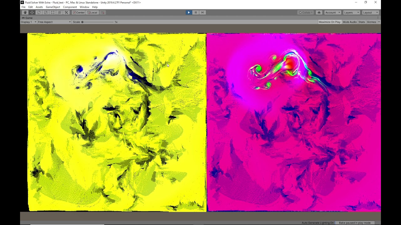
Yeah i know. I can make Texture2D<float> and make SamplerState ClampLinear and use it to sample. But not in this case! I'm writing fluid solver right now and though "Hm there is InterlockedAdd. what if fluids moved forward like it should instead of just pointing vector backward and sample". But in this case i should move stuff along vector field and spread it as it is bilineraly interpolated. So it backwards.
Looks cool https://youtu.be/Sup2UIBZ2K0 but with bunch of issues that i did not expect to see and now i'm sitting and fixing it.
Dw, I just pulled a 2head move and forgot that I could just delete the mesh renderer component. No shader needed. :D
Ty for the response though!
Random question:
Could i potentially write a shader that reacts to the normal of the pixel?
For instance, you have 6 directions, up/down/left/right/forward/backward. I assign a color to each of these 6 directions.
For anything inbetween i linearly interpolate. Perhaps also with a gradient.
this would be for an isometric game.
Still reading a book about shaders, just would like to know the answer to this in advance
This game looks like it would use such a technique, as there aren't any shadows or such. But are using gradients:

pretty sure Jason just assed support for something like that on his Better Lit Shader
there's probably some examples around for such thing
I'll have a look. Thanks
Just out of curiosity: is there something you cant do with shaders?
anything with alot of branches often wont work well on shaders
i have a vertex shader i need to output relive to the screen, so for example if i have the point 0,0,_ i need it to go in the middle of the screen regardless of the projection or transformation matrixes. all my attempts seam to have some transform still being applied
This is so cursed... CommandBuffer.DrawRenderer works for me in scene view but not in playmode... Dang URP.
Most all lit shaders "react to the normal" somehow. The HOW is up to you.
For example, you could just output the normal (maybe remapped) as a color, you'll find that interesting for debugging if nothing else, but it would be similar to what you are asking....each axis would get a value. X would be R, Y would be G and Z would be B. But normals are signed usually, so you remap them to avoid negative values. So instead of going from -1 to 1 for each component of a normalize surface vector, you'd remap it to 0 to 1.
That's done with:
float3 remappedNormal = sufaceNormal * .5 + .5;
IIRC.
P.S. but I don't think those sample images are doing what you think they are.
basically yes, you can get world normal even with shader graph and remap it so that you'll get different colors per sides
The remappedNormal is interesting. Definitely makes blending easy without if statements 😮
Looks like this will be an easier shader to try and program myself. Wish me luck!
Is there any benefit to using shadergraph vs programming it manually?
I dunno if I'd make such effect purely on shader, there's a lot of things you may want to handle manually
also when you know your asset constraints, you can make smarter decisions about it vs trying to make some general purpose shader that you just slap on all assets
Last time i tried node programming was with Grasshopper in Rhino3d. Never liked it much 🙃
But i suppose shadergraph would allow me do component-ify my pieces
i think shadergraph is set up to be easy to use and to avoid some pitfalls you make when coding it manually
but you can get more performance out of doing it with code if you know what your doing
Atleast for me, shader coding is also much faster way to make shaders and easier to understand than shader graph (complex shader graphs gets very messy really quick)
Lets say someone sends me image of shader graph and image of shader code. It takes heck a lot more time to make any sense of the shader graph compared to shader code

Add depth to your next project with COLR – Coloring Redefined from Dustyroom. Find this & more VFX Shaders on the Unity Asset Store.
I would agree after looking at a shader graph tutorial. 5 boxes just to get a dotproduct of 2 vectors times a color? And do this 3 or 6 times, so 30 boxes.. no thanks
Well what do you know 🙂
Thanks!
Its perfect
How can i get an objects angle in relation to 0,0 in the scene in a shader graph? Like if the object is at 1,0 i want 90.
Or radians, whatever is easiest. 🙂 i will plug this into the rotation of an overlay shadow shader i’ve made and 0,0 is the sun location.
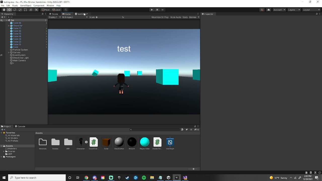
Is there a setting that would cause a render texture to have a very low scale? It's rendering smaller than what the camera is seeing and I don't want to simply increase the size of the object because I am working with pixel art and need it to be the correct pixel scale.

that tiny red dot on the left is the render texture, default settings
Could probably use vertex id. I'd just split the mesh into submeshes and use 2 materials instead. Not sure if that fits your use case though.
Well, it's possible to pass the vertex it into the vertex shader to identify what vertex is being processed.
For HLSL you can see it here in the system-value semantics
https://docs.microsoft.com/en-us/windows/win32/direct3dhlsl/dx-graphics-hlsl-semantics
I believe they are in the same order as in the C# side Mesh.vertices array.
I'm not sure what exactly you're trying to do, so can't really answer that.
just adding a bit to dlich's suggestion. There are a lot of different ways to do this. If the part of the mesh you want to affect is not changing, you could use a texture and treat different parts of the mesh differently depending on the color of the texture at those uv coords. You could use vertex colors. You could use uv2, kind of like this post is using for AO https://stackoverflow.com/questions/19136494/unity-3d-multiple-uv-sets, and base some decision on the value of the uv you passed in.
I'm not great with shaders, so (1) something I said may be wrong and (2) I can't really tell you which ones of those are good options, but I know there are a lot of options.
Trying to figure out how i can rotate individual tiles of a tiled texture in shader graph
No, unity does frustum culling as efficient as it can. "Your own culling" might just be inferior and prone to bugs.
Although, it might be good enough for your use case.
Because that's not frustum culling.
Frustum culling is just culling things that are outside of the camera cone(frustum)
What you describe is occlusion culling, and you have to specifically bake it in your scene for it to work.
Also, that question has absolutely nothing to do with shaders...
there's a reason why asset store is filled with all kinds of custom culling solutions
and that Unity is actually working on new occlusion culling system
Summary
Burst Occlusion culling is an optimization workflow that improves rendering performance by excluding static and dynamic Scene objects from further processing and rendering when obstructed and not visible from the rendering view. Burst Occlusion Culling is a dynamic culling solution and, as a result, does not have the upfront cost of...
ye
Because occlusion culling imposes other downsides, like increased build size. Not every game needs that. For example, mobile games prefer lower build size.
that new burst thing doesn't require offline baking btw, so that would result in lower build size too (at least that's my impression from that)
Yeah, still some scene layouts(huge open areas) wouldn't benefit much from it. Although, I guess they might take that into account.
here's some staff comments about that new burst culling if interested: #archived-hdrp message
and tl;dr: it's not available, with some luck we get something to play with in one year or so
and then you add in Unity factor for everything taking year or two more than estimated, should be good to go in 2023
not trying to make fun of them, just trying to set more realistic expectations
personally I'd love to test that stuff already
unity has baked occlusion culling, frustum culling and backface culling already (and depth testing ofc). only realtime occlusion culling doesn't exist yet. the thing is: it's pretty hard (and quite expensive ig) to calculate precisely what objects are behind and what objects are on top of each other. on some games realtime culling system would save barely anything. occlusion culling is best for narrow indoor scenes and worse for extensive outdoor scenes where there's very few things behind others at a time. anyways, it seems unreal has better options for culling at the moment. they seems to provide some sort of realtime occlusion culling (using power of GPU it seems) as well which could be nice feature on some cases.
Does anyone know how URP shaders aren't stripped without being in Resources?
I'm trying to make a reusable package and I kinda need to load a shader for the screenspace effect without user input.
Oh wait, I guess scriptables.
Addressables perhaps.
Nah, I shall not touch that monstrocity ever again.
Hey I really need help making a vertex displacement shader for the built in pipeline. there seems to be no documentation on it and no tutorials for writing it (only for shader graph) any ideas?
Thanks
Anyone knows how to expose the UV0/UV1/etc.. choice as a property ?
I tried using a Vector2 but i can't figure out what values the node expect to match "UV0" or "UV1"

You'll probably need to use an Enum Keyword and set each entry to a UV node with each channel.
It creates multiple shaders under the hood like branching; right ?
or do something silly like this?

Branching doesn't make multiple shaders, but yes. If you don't want multiple variants you could likely also use Booleans and Branches
looks horrible though
Yeah, and if you want all 4 channels you'll need more branches 😛
sounds messy yes 😄
and doesn't branching creates variants too ?
Ideally i want the dropdown from the TilingOffset node exposed
Well the Branch node isn't a true branch afaik, it's just a ternary which always calculates both sides
and simply linked to one node
Oh so it's expensive within the shader but doesn't create variants ?
(i mean expensive depending on what is on both sides)
It's not really that expensive in this case since the inputs are just UV nodes, but yeah Branch nodes won't produce multiple variants
ok, thanks a lot for the precisions ! 🙂
i'll use some branches until i find a direct way to expose the node property

for now i only need UV0/UV1 switch, but if i need more i guess keywords enums will come handy even if it creates variants
The keywords / multiple variants probably is a bit overkill tbh, I'd stick to the branches. Can always put it in a SubGraph so you don't have to look at it, or write it as a custom function instead like the above
oh ok
This tutorial is pretty good for vertex displacement in built-in, https://www.ronja-tutorials.com/post/015-wobble-displacement/
Can also do the same sort of thing in the vertex shader of an unlit / vert/frag shader rather than surface, just be sure to do it on the vertex position input before converting to other spaces.
Noob question: I just started messing around with shaders in the URP. What do I need to do to make the alpha/alpha clip threshold accessible?

Enable alpha clipping in the graph settings
Wow I'm dumb. Thank you so much @vocal narwhal
Now I have a new issue. Is there a way to set what the value of Sine Time is when the shader is set to the renderer of an object. I.E. Is there a way to make sure that when I assign the shader, it will begin fully opaque and then go to transparent before the gameobject is destroyed instead of starting at a "random" point in the cycle.
@candid jewel your shader doesn't know about gameobject states at all by default, simplest way to do this is to handle the fade on your c# code and sync the wanted alpha value via some exposed shader property
Could pass in the start time as a property, then subtract that from time, and feed the result into a sine node yourself maybe?
Does anybody have an idea on why this material doesn't react to alpha or color changes in the particle system?

Connecting a Vector4 directly to a Vector1 port (e.g. Alpha in this case) always takes the first/red component. You need to Split and take the A output instead.
However, since the graph is named "ParticleAdditive" I'm assuming it's using additive blending, which means the alpha port isn't actually important. Instead outputting a colour of black (0,0,0) becomes fully transparent (since adding 0 doesn't change the colour on screen). If you want the alpha from the particle system to affect the transparency rather than only relying on colour, you could Split, take the A output and Multiply your current colour output before connecting it to Base Color. (Hopefully that made sense)
As for the colour part, I'm not sure why it wouldn't currently change with the particle system. Make sure you save the graph (Save Asset in top left) as there's a "*" on the window tab meaning it hasn't been saved. Perhaps that's why it's not changing colour?
Alright so funny enough, the one with split does react to alpha but doesnt react to color, the one without the split, doesn't react to alpha but reacts to color. Getting so confusing when trying to test x)

The left one doesn't react to colour because the Base Color is using the one before multiplying with Vertex Color. You want to use the output from the second Multiply instead
Oh sweet, I think I've got it, thank you
Although another difference, both of them have a blending mode set to alpha, but the right one takes the black as transparency but the left one doesn't
I probably have it set to additive somewhere where I forgot about so maybe you have an idea on where else can the blending mode be changed?
Might be an override for the blend mode on the material if you're in Unity 2021.2
hi guys, i have this sprite graph shader that moves by an offset to move a voronoi texture and i want to change the offset randomly at the beginning for each line that uses the shader, how do i do that?

I'm on 2020.3, should I look for it in the shader graph?
any hack to sample scene color after transparency was rendered on URP?
hey guys, i just want to ask y'all what kind of shader are u using for terrain? im using microsplat atm, but i dont really like how it looks
could you share that using codeblock or pastemyst or smth?
oof that's surface shader, surface shaders doesn't exist in urp (atleast yet). there's no way to convert that to urp shader code. you can still try to remake that using lit shader graph which is pretty much same as surface shader
that doesn't seem too complicated shader tho. whould be doable if you're somewhat familiar with shader graph and surface shaders (which i'm not, I have never mady any sufrace shaders, still I managed to convert one surface shader into lit shader graph)
then there's no way (unless you get someone to do that for you)
Has Anyone used 2d Shaders with SVGs?
I Think there is some sort of Problem when i am not using sprites.
so can anyone tell me about what shaders are u using? is it mostly self created from nodes?
@regal stag Why are depth textures not working at screen edges?
Can you introduce good stuff/movies/tutorials to implement nice cool weapon skins like skins in cod mobile/pubg and fortnite?
I have implemented some skins. They are animated skins in local space.
It seems OK in y-z plane (up/down and forward/backward) but in x axis, I see some stretch in patterns
It is the correct way to create these patterns in local space or it should be in uv space?
The bubbles move from the barrel point towards the butt
Hi - I made a library a little while back for procedurally generating guages/scales (think car speedometers). I got stuck and parked it once I realised the performance was shocking. I clearly need to do something with shaders, but am a bit of a loss of where to start. Can anyone guess what kind of shader I should start playing with? It can currently do 2D and 3D lines with ticks.
I can probably generate a strip mesh quite efficiently that bounds the surface I would want to draw on. So I am imagining drawing lines on a mesh surface using parameters handed in. Ideally I don't want to prevent users applying their own textures and effects over the top of the outline/shape I am generating. Does anything seem like an obvious starting point or best choice to use?
I imported a ripple effect nothings happening when i call it does someone have any idea why its not working ??
Not a great video but I asked about setting the starting point of a shader animation last night through script. I got it working 🙂 https://youtu.be/EIxM_xBMeYM
Code presented in this video: https://pastebin.com/vKTZSZFb
If anyone else was curious about it
Guys
I've just found something funny xd
If you ever make a shader in unity shader graph think deeply about the names
since if you change any name of any property later on you have to re asign this value in every single material it is used in!
i learned it the hard way after making my scene i went to clear up some mess and decided that "albedo" isnt a good name i will try "_BaseMap" maby it will conver materials better form hdrp
SIKE! you cant every materrial in the whole project got black
Thanks unity Very cool
well.. not sure what you expected
if you change shader property name, your materials will be clueless of this
for time before shader graph i was using amplify shader
name chaning was never an issue
so yes i expected quality sorry
name change isn't, property change is.. but SG does automate this
you can still manually override the property name under it
btw is there a way to set up autotransfer from hdrp lit shader to shader graph shader
like you know
you'd rather have SG give some generated property name that is not descriptive?
so it knows where to put albedo mask and normal
yeah, using those same property names
you could make diffrent types with amplify shader even global values
if you map your SG properties to use exact same naming as HDRP Lit, swapping HDRP Lit to your SG will map the properties automatically right
is it possible to do it now?
yes, I've done it many times
i assume thew names are
_BaseMap
_MaskMap
_Normal
albedo is bit tricky as Unity has swapped the naming convention on it and which one is right depends on your SRP pick, basemap could be right but would need to double check
normal one probably needs Map suffix too
but without having to guess, you can just check these on HD Lit shader
which HDRP version are you using?
2021
2021.2?
well, they haven't changed this recently so it wouldn't really matter, just trying to get more relevant link for you
you can see all property names there
_BaseColorMap is what you need for albedo texture

you don't, if you change that, it will break existing materials that used that
but if you want to make HDRP Lit swappable shader, using these values would let you swap your SG in place without losing those material refs
this also isn't officially recommended way of doing this, more of a hack. I believe Unity would want to reserve some of these property names for their internal shaders only
there were some things where some of these had some hidden agenda but I don't really remember it anymore
also, if ASE works more like you prefer, why even use SG?
(I really get why some prefer ASE, it's pretty cool tool)
because ASE shaders are not marked as SRP batcher compatible and i dont know how to fix it
huh, you'd think their templates would be srp batcher compatible by default
and yes many things are hidden
some time ago i tried making triplanar pixel displacementshader in shader graph and i dont think it is possible
have you asked about this on Amplify discord?
i dont remember the decision was made like a year ago maby
Hello everyone. So, I'm using a blit material feature to render custom post processing in urp. The effect I want to achieve is a depth based fog and it works kind of, the only issue is that the parts which aren't affected by fog are drawn gray instead of normal


You may want to share the graph/shader for your Underwater material. Are you sampling the _MainTex?
how would i imitate this effect but with a texture?

i dont know how i can explain it but i want it like a sort of projected texture
Sure, I'm just not on my pc right now 😄
Also, that blit feature is made by you actually @regal stag
I've got a list of angles I'd like to render as gradient circles to represent stars. I'd really like to do it on GPU as a pass on my skymap shader, but there are several thousand points that it would have to check. Would I be screwing my frame rate over having it do a dot product check thousands of times per frame? I need it to rotate as the player changes lat/long, so I'd prefer to do it procedurally instead of baking it into an image.
I'm pretty new to shaders though, anyone have strong feelings about the best approach?
hello everyone, is it possible to make a shader that makes everything when looking at a given direction? I have a room where parts of it looks dark because the light object is facing one direction but the other doesnt from what it looks and trying out point lighting or spot lighting doesnt really solve that for me
i think i know what you mean, like the texture moves with the screen and looks like it’s being projected from the viewpoint of the camera?
i believe to do that you input the screen position as the uv for the texture
A really weird bug is happening, when I put on a "vrchat/mobile" shader parts of my model becomes black. I looked all around online for a solution but couldn't find anything. Is there a solution to this?


thank you for your time
Both gameobjects have the exact same material applied, but the lineRenderer (right) has a much darker color, the one on the left is a basic cube. I am not sure why this is and I would like for both of them to be the same color.

I was not sure what channel to place this in
can someone suggest me a better shader book?
I’m a couple pages in and finding it lackluster. They just spent a few pages on how add a directional light, plane, and a sphere to your scene…
I’m reading unity shader cookbook
Heyas! Does anyone know much about these grass generating shaders? i cant even begin to get one to work, letalone how i need it to
Oooo i sort of got a Botw style grass one to work, but its rendering EVERYWHERE, and i know nothing about making it ranged 😦
These? Which one?
https://www.youtube.com/watch?v=MeyW_aYE82s I have this one working now, but it chonks my PC with all the grass. Im trying to figure out now how to shorten the range they render in

Breath of the Wild's grass is visually striking and helps to break up large areas of ground. In this tutorial, learn how to make stylised grass just like it in Unity URP using geometry and tessellation shaders!
👇 Download the project on GitHub: https://github.com/daniel-ilett/shaders-botw-grass
✨ Roystan Grass Shader: h...
i havnt used unity in over 2 years, im rusty
so I made a shader in shader graph, but how do I actually use it? the .shadergraph file its saved in, isn't an actual applicable shader, and i don't see any sort of "save this as a shader" kind of option?
you should be able to select it on the material same as any normal shader.
one more, new to shaders as a whole. any obvious reason why the results are SO drastically different?
also its not animating...for a reason.
Can't say for sure without seeing the shader graph
Syntax question. Can i have sort of generic functions? Like if i set as input Texture2D<float> then function return float. If int2 then it return int2. tried to make it with #define and it ugly as sin
Hello, anyone here knows hlsl? i am trying to include the URP lighting,(i am actually following a tutorial on youtube) but somehow, it doesnt complie, i cant get the light to work!! i've been messing with it for hours now. and this little thing stomped me so hard

by chance, are you using compute shaders
No.
I just copied the RenderObjectsPass and modified it to draw to a non camera target instead.
Yes.
Yes.
one sec I am grabbing some links. I ran into this a month or two ago and discovered zero documentation or forum posts on it but I finally found some resources a few weeks ago
Okay, first a little context you might or might not know.
RenderTargetHandles act as a wrapper for an int id and a RenderTargetIdentifier.
From here forward I'll use rtid as shorthand.
This int id can be thought of as the result of Shader.PropertyToID();
A rtid can then use this id as a pointer for what object it should use.
RenderTargetIdentifier is not the same as a Texture object or a RenderTexture object. It is an abstraction.
RenderTargetIdentifier: https://docs.unity3d.com/2021.2/Documentation/ScriptReference/Rendering.RenderTargetIdentifier.html
Constructor: https://docs.unity3d.com/2021.2/Documentation/ScriptReference/Rendering.RenderTargetIdentifier-ctor.html
RenderTargetIdentifier has a lot of constructors, allowing it to be created using:
• BuiltInRenderTextureType
• string name
• int nameID
• An existing RenderTargetIdentifier
• Texture
• RenderBuffer
For now*,
ScriptableRenderPasses (like RenderObjectsPass) use RenderTargetIdentifiers for their render targets. You can see that here:
*There are changes to simplify this currently in URP 13 and is part of a larger effort that I won't go into for now.
Now I'll send the stuff about the error specifically (sorry 😅 ).
@solar sinew where's the rest of it 👀
OKAY.
TLDR: Don't use RenderTargetHandle.
I got rid of this error by caching my own int id and/or using RenderTargetIdentifier instead of using RenderTargetHandle.
The error is caused by RenderTargetHandle using an id out of range of kShaderTexEnv which seems to be -2.
The only forum post I have found that mentions this is here:
This is RenderTargetHandle
    // RenderTargetHandle can be thought of as a kind of ShaderProperty string hash
    public struct RenderTargetHandle
    {

        public int id { set; get; }
        private RenderTargetIdentifier rtid { set; get; }

        public static readonly RenderTargetHandle CameraTarget = new RenderTargetHandle { id = -1 };

        public RenderTargetHandle(RenderTargetIdentifier renderTargetIdentifier)
        {
            id = -2;
            rtid = renderTargetIdentifier;
        }
If you Initialize RenderTargetHandle with a RenderTargetIdentifier, id is set to -2. You can see this more clearly in the code below.
        public void Init(string shaderProperty)
        {
            // Shader.PropertyToID returns what is internally referred to as a "ShaderLab::FastPropertyName".
            // It is a value coming from an internal global std::map<char*,int> that converts shader property strings into unique integer handles (that are faster to work with).
            id = Shader.PropertyToID(shaderProperty);
        }

        public void Init(RenderTargetIdentifier renderTargetIdentifier)
        {
            id = -2;
            rtid = renderTargetIdentifier;
        }

        public RenderTargetIdentifier Identifier()
        {
            if (id == -1)
            {
                return BuiltinRenderTextureType.CameraTarget;
            }
            if (id == -2)
            {
                return rtid;
            }
            return new RenderTargetIdentifier(id, 0, CubemapFace.Unknown, -1);
        }

        public bool HasInternalRenderTargetId()
        {
            return id == -2;
        }

    // Some other code for RTHandles, which will replace RenderTargetHandles.
    }
You can think of RenderTargetHandle.Init() like this:
private string exampleName;
private int exampleId;
private RenderTargetIdentifier exampleRTId;
private RenderTargetHandle exampleHandle;

private void ExampleSetupFunction(string texPropertyName)
{
      exampleName = texPropertyName;
      exampleId = Shader.PropertyToID(exampleName);
      exampleRTId = new RenderTargetIdentifier(exampleID);

      exampleHandle.Init(texPropertyName);
      // id = Shader.PropertyToID(texPropertyName);
      exampleHandle.Init(exampleId); // Gets type-casted to RenderTargetIdentifier
      // id = -2;
      exampleHandle.Init(exampleRTId);
      // id = -2;
}

private void Execute(CommandBuffer cmd, ref RenderingData renderingData)
{
      ... some use of exampleHandle.Identifier();
      // RenderTargetHandle.Identifier() will return either CameraTarget or rtid depending on the value of id.
      exampleHandle.id;
      // Will return id set in .Init() which may not be using your shader property id
}
An id of -1 is the id used for the camera texture.
The id will be set to -2 which seems to be outside the range of kShaderTexEnv.
Unity Forum
Hi, My compute shader needs to access a temporary rendertexture that was allocated by cmd.GetTemporaryRT(...) from previous frame, but then Unity warns...
Ohh, so .id is not actually the id I need.
Use int id instead
Sorry, I know it is long-winded
but I once solved this and then forgot why it happens and then ran into it again.
Big thanks, I guess I will pass around RenderTargetIdentifier instead.
Oh wait, it doesn't expose the int hash, back to barebones ints I guess.
yep! and if you happen to create an temporary RTs remember that their constructor takes id not RenderTargetIdentifier.
But for functions like ConfigureTargets(); you need RenderTargetIdentifier or you can use id and it will be type-casted.
If you need to connect an id and a RenderTargetIdentifier make sure to do this when it is declared:
    private string                 colorTexName; // Set this string however you want
    private int                    colorIntId    => Shader.PropertyTOID(colorTexName);
    private RenderTargetIdentifier colorTargetId => new (colorIntId);
or something like this in where the RenderTargetIdentifier is defined:
        string textureName;                     // Set this string however you want
        int renderTargetIntId                   = Shader.PropertyToID(textureName);
        RenderTargetIdentifier targetIdentifier = new RenderTargetIdentifier(renderTargetIntId);
Yeah, I just need to use the same pass both for temporaries (which requires an id) and for persistent RenderTextures (so I can bind them to VFX Graph, and requires a RenderTargetIdentifier). So that's why I thought RenderTargetHandle was the way to go.
I'm glad I finally found this info, there is essentially nothing online about this
Yeah, so basically they have 2 abstractions and neither let you to hold either a texture or a temporary AND let you extract the id haha.
and the newer RTHandle is a new layer of abstraction which simplifies things and takes into account render textures of different sizes.
I shall see it for myself then when 2021.2 stops giving me 28 compiler exceptions on every domain reload 😅
btw, if you happen to run into something along the lines of Property has mismatching output texture dimension (expected 5, got 2) (which is an only slightly less frustrating thing to search for).
That is referring to this:
2 and 5 being Tex2D and Tex2DArray

This can happen because of weird behavior with XR macros (I do not make anything XR).
just FYI
Hi guys, does anyone know any method to use the proximity of a game object to modify some value in the shader of another game object? More specifically I would like to make a certain area of an element visible according to the proximity of a character. Preferably by Shader Graph.
sure - just pass in the position of the other object to the shader as a property. then you can check distance of your vertex or fragment to that object.
I see.
That's sounds like what I need. Can you give me more details? I'm not an expert.
In the blackboard you create a property https://docs.unity3d.com/Packages/com.unity.shadergraph@10.8/manual/Blackboard.html
You can make it a Vector3
basically, TEXTURE2D_X is a macro found in universal/ShaderLibrary/Core.hlsl.
Depending on whether XR stuff is turned on, TEXTURE2D_X will return either a Texture2D or a Texture2DArray. This may sound like something you would never need to know, but you would be surprised at what you run into when writing Scriptable Render Passes
Then you just can set the value of that property on your material at runtime with Material.SetProperty("MyPropertyName", someObject.position); for example @tranquil jasper
Ah, I always throw XR support out when writing custom passes 😎
Only SAMPLE_TEXTURE2D in this house.
I was rewriting/copying some HDRP code for URP and mistakenly had left in #multiple_compile DISABLE_TEXTURE2D_X_ARRAY. All my textures were expecting dimension: Tex2DArray because both versions of the shader were being created 
SAMPLE_TEXTURE2D_X() will return SAMPLE_TEXTURE2D() but I just avoid it because XR support can stay away from me

VR market is small, no need to support it 
but anyways that is why you will see SAMPLE_TEXTURE2D_X() and TEXTURE2D_X() in internal code. To support stereo rendering
It's the only way to figure anything out 😩
Have you opened HDRP 👀
I will take reading URP any day.
Certainly beats jumping 4 hlsl headers to find where the shading is.
Oh god, so many global variables. At least QoL fixes in URP and SRP core changes are making them realize how much weird code is in HDRP
Not to mention graphics settings on the asset only being accessible through reflection 😛
Hey everyone, I know I've asked for help before regarding some issues with a depth based fog effect I am trying to make, and @regal stag asked to share the actual shader, so here it is: https://paste.myst.rs/s8j1jn28
a powerful website for storing and sharing text and code snippets. completely free and open source.
I'm a beginner with shaders, and I don't know whether or not the issue is caused by the sahder, or something else
Hello everyone!
Can someone help me with my sub shader graph? I am trying to expose some variables in my custom node, but I don't know how can I do it. Mi idea is upgrade my node to get global variables and modify them from code.
Might want to link to the original question so it's clearer for others what's wrong with it too, #archived-shaders message
I don't particularly like the use of tex2Dproj in a hlsl/URP shader as I've only seen that used in built-in with sampler2D. It might still work with separate texture and sampler but I'd use SAMPLE_TEXTURE2D(tex, sampler, uv) instead to be safe, with uv as screenPos.xy / screenPos.w to do the perspective division that tex2Dproj does.
You are sampling _MainTex so that's good. If you can't see any colour from the scene it might be that the _FogDistance value is just too small? (Try setting it to 100 or 500 or something). I can't really see anything else it could be
So I did some research and it turned out it might be due to a bug in 2021.2 in which a blit material feature is glitched
I tried with a few other blit material feature implementations and only 1 out of 3 worked
I'm not entirely sure though
Thanks! I will do some research of how to apply that 😄
Hmm, I did recently make some fixes to the feature for 2021.2. You may want to download it again to make sure you have the up-to-date one. https://github.com/Cyanilux/URP_BlitRenderFeature
But with your screenshot from before it looked like the feature was changing the view, so I would assume it is working. Unless the blue colour is just the skybox or something.
Yeah, your blit implementation is the only one which worked
Also your post on writing shader code in urp is a life saver, I'm more than grateful that it exists
trying to make this volumetric kinda effect, but the color of the volume is just white instead of the light color, here's my code:
https://pastebin.com/YgMkEDji

Is there any way to do raycasting in Compute shaders?
if you have more than one light in your scene "_LightColor0" might not be the red one
I figured it out. I just set all the colors to value2 instead of value2.r, value2.g, value2.b
pls pls pls can some one help me!
i looked every where
how can i use shader graphs in the ui
while in overlay - renderer mode
https://youtu.be/L_Bzcw9tqTc?t=893
at this specific timing of the video, is it possible to lerp between vertex colour (such as the R channel) instead of lerping between the Y value of the UV?

Let's learn how to make realistic grass with Unity Shader Graph!
This video is sponsored by Unity
● Download grass assets: https://ole.unity.com/grasssway
● Art That Moves: https://bit.ly/2VW85He
● More realistic vegetation: https://bit.ly/2EAxC5d
● Mesh Generation: https://bit.ly/2u7vee3
♥ Support Brackeys on Patreon: http://patreon.com/b...
If you can dream it you can do it
hm?\
i've only seen people lerping between "black & white" so im unsure if it would work for vertex colour...
You just need two colors and you can lerp between them
vertex colors are generally already interpolated for you in the fragment stage though
not sure what two colors you'd be lerping between yourself
i.e. if you read from the vertex color node in the fragment stage you get a color that's already interpolated from the actual vertex colors based on the barycentric coordinate of your fragment
ah i see i see
Anyone seen this when upgrading to ShaderGraph 10.2.2 -> 12.1.2

don't understand exactly how to solve this. if I simply replace the simple noise node, it's still showing the error
if I delete it, my graph compiles fine
Does anyone know the stage at which skinning occurs in the rendering pipeline?
I need to compute some information over the mesh using a compute shader, but it needs to be computed after all deformations have been applied
I'm struggling to find documentation on this - what I've read says skinning occurs in the final vertex/frag shader, but it's not specific
Do I need to pull skinning into a compute shader and run it first if I want to do something like this?
Hey uhm, what shader do you guys typically use for binary transparency shaders in HDRP?

Im having some issues with alpha sorting 😅 Didnt think I was gonna have issues with that as my transparency maps are binary (Im using alpha clipping rn)
Is there no like order independent transparency in Unity
like
at all?
^ Created a forum post/question on it https://forum.unity.com/threads/is-there-no-order-independent-transparency-in-unity-hdrp-only-need-it-for-binary-transparency.1215635/
Unity Forum
Hi, Ive been trying to find some mesh surface material that I could use to solve this madness: Imgur: The magic of the Internet [IMG]
Were using HDRP...
@tropic smelt#archived-hdrp message
of course the day that actually gets merged, it's like 2022.2 or 2023.1
So that means transparency sorting isnt a thing rn?
not afaik
I haven't tested this exclusively on HDRP but I'm under impression it doesn't really handle it gracefully
I know for sure that URP fails big time on that one but I never specifically tested this on HDRP
why do you need transparent material for that btw?
Right, well is it possible to manually merge the latest master of https://github.com/Unity-Technologies/Graphics into an existing project? Not that I think the guy responsible for the project would ever agree to something that risky, but still

GitHub
Unity Graphics - Including Scriptable Render Pipeline - GitHub - Unity-Technologies/Graphics: Unity Graphics - Including Scriptable Render Pipeline
your b&w image wasn't really all that clear on your intent
not to 2020.3 but you can run master on 2022.1 betas
but I don't even know if that branch is functional or if it's even meant for stock HDRP
Im working on a project where the developers are very poly count aware, they essentially strafe for PS3 polycounts pretty much. So Im forced to be a little creative with finding ways of adding detail anyway
since it mentions GPU pipeline, it's probably meant for the new gpu driven batched rendering
Therefore I use transparent materials to add some detail that I otherwise could never afford, such as this

but at the same time looking at the files, it looks like it's mainly touching regular HDRP files
so would need further testing
if it works or can be made to work, you could probably just squash the commits into one and cherry-pick that on older engine and then handle the conflicts there
right, its a large project with several houndred C# files and loads and loads of VFX, I guess things would break if we try using that?
I still don't see why that has to be transparent
can't you just do opaque with alpha clip for that?
Thats what you are looking at
so what you need OIT for then?
Binary transparency
wdym?
you get sorting issues if you use transparent shaders
If youre asking me to cut out the areas on the mesh that are supposed to be transparent, that would blow up my poly counts too much
with opaque the order shouldn't be similar issue
@fervent tinsel is this what you meant?
I don't really see how that affects poly counts at all
I'm now talking about opaque shader with alpha clip option, you feed the "cut out" parts just 0 alpha to the shader
stuff that people do all the time with foliage
This is what the shaders look like rn

doing same thing with true transparent shaders would be crazy expensive, all the overdraw
Yep, I def don't want overdraw where I dont need it (which I dont rn) 🙂
basically just change your material to use Opaque surface type and enable alpha clip
unless, I somehow misunderstand what you are trying to do here
oh lmao 😄
That simple
Yeah it looks like the sorting issues are gone just switching my materials from transparent to opaque
I just assumed they had to be set to transparent for the alpha clip to work
yeah, the ordering issue is typical on transparent materials, it's hard problem to solve there. if you can use opaque you'll be having so much better time
this is why many often do fade out effects with some dithering effects using opaque passes instead of true transparent shaders etc
oooo right, does Unity support alpha hashing out of the box?
I don't really know the technical details other than it being like this on all engines I've used in past decade or so 😄
some have implemented optional OIT to fix this though
but even that is nontrivial as afaik it comes with it's own burden
@fervent tinsel I have another (totally unrelated issue) when youre well here
Are there any tricks I could use to hide the shading issues on my bars here? (I know its horrible and that I probably should fix it in my 3D software, but again, Im trying to save polygons to quite extreme levels)

I should probably just make it unlit maybe
you'd probably need to bake those normals from high poly for that extreme setup
it's also possible your bars have incorrect mesh normals too but those can do only so much in the end...
Hiya, do you folks know of any examples of addative geometry shaders? I've been digging around but haven't found one yet. 😦
(Unity can recompute the mesh normals for you as well)
I weightened the normals in Blender to minimize the issues lol, those bars are really low poly
with a strong enough normal map you could recreate that entire ship with a cube thats like 8 poly's
yeah, if you don't have enough polys to do that proper, you typically have two options,bake the whole thing from high poly or use some normal map trim sheets.. but considering all the angles there, that option is likely to be way too tedious
of course one could do all kinds of shader trickery too but it's probably just easier to bake the normals
bake everything. make it a habit. even if end result doesn't need it, better to have it in case
I'd like the back portions to just not appear (as usually works with additive blend modes) but it seems I'm missing something. I'm using Blend One One but to no avail

please ping me if anyone has a solution
Maybe it's a negative number and it adds a negative value to it
do a: max(0,color) thingy
why doesn't normal from height shader graph node work for tesselation displacement in hdrp
@shrewd crag you need LOD type sampler node for vertex stage
I assume you mean "black portions" not "back portions", but if so, you're not using additive like you think you are, or they wouldn't appear, as you say.
Maybe pastbin (or whatever) your shader code.
Also, what render pipeline (I assume built in) and/or what render queue are you in?
my objective is to procedurally generate the tessellation
Hello. What is diffrence of surface and vertex/fragment shader? i read only Surface shader is slower than v2f shader. My object is created mesh by datas of color,reflectivity, etc... and i tried to write a v/f shader but i have problem with light (1st time writing the shaders be honest) ... what do you think? stay at v2f shader or try surface?
Surface shader is a kinda like syntactic sugar by unity that combines both vertex and fragment. It compiles into proper vertex + fragment shaders afaik.
So, if you need more control, you should probably use the vertex+fragment shaders.
is there a way to make a specific part of a skinned mesh renderer glow
Surface shader is like the lit shader in shader graph and vertex/fragment shader is like unlit shader. Surface shaders are meant to make it easy to make shaders that can interact with lighting correctly. Same way as the lit shader graph, on surface shader you just calculate main color, smoothenss, metalness etc. in the shader and the surface shader takes care of the lighting calculations with those give inputs. If you want to make vertex/fragment shader that needs to be affected by lights, shadows etc., you have to code all the light calculations yourself which is possible but much harder than using surface shader.
Assuming you are using sriptable render pipeline, you can make shader graph (on build in rp use surface shader) to make it glow on some parts. The only problem being, you have to somehow specify where that part is. You can for example make a texture that sampled to mesh tells the glowiness or save the glowiness to second uv coordinate for instance. You have to save the glowiness in a way its accessable by shader
You could actually just use emission map if you want to use texture to indicate glowing parts https://docs.unity3d.com/Manual/StandardShaderMaterialParameterEmission.html
{
    Properties
    {
        [NoScaleOffset] _MainTex ("Texture", 2D) = "white" {}
        _Strength("Strength", Range(0.0, 1.0)) = 0.5
    }
    SubShader
    {
          Tags { "RenderType" = "Transparent" "Queue" = "Transparent"}
            LOD 100
            GrabPass{
            }
        LOD 100

        Pass
        {
            CGPROGRAM
            #pragma vertex vert
            #pragma fragment frag
            // make fog work
            #pragma multi_compile_fog

            #include "UnityCG.cginc"

            struct appdata
            {
                float4 vertex : SV_POSITION;
                float2 uv : TEXCOORD0;
            };

            struct v2f
            {
                float2 uv : TEXCOORD0;
                UNITY_FOG_COORDS(1)
                float4 vertex : SV_POSITION;
                float4 screenUV : TEXCOORD1;
                fixed4 diff : COLOR0;
            };

            sampler2D _MainTex;
            float4 _MainTex_ST;
            float _Strength;

            sampler2D _GrabTexture;

            v2f vert (appdata_base v)
            {
                v2f o;
                o.uv = v.texcoord;
                o.vertex = UnityObjectToClipPos(v.vertex);
                UNITY_TRANSFER_FOG(o,o.vertex);
                o.screenUV = ComputeGrabScreenPos(o.vertex);
                return o;
            }
            fixed4 frag(v2f i) : SV_Target
            {
                fixed4 c = tex2D(_MainTex, i.uv);
                float4 displaced = float4(i.screenUV.x, i.screenUV.y, i.screenUV.z, i.screenUV.w);
                displaced += c;
                displaced = lerp(i.screenUV, displaced, _Strength);
                fixed4 grab = tex2Dproj(_GrabTexture, displaced);
                return grab;
            }
            ENDCG
        }
    }
}
I'd like this window shader to have specular highlights. any way to do that with V-F shaders?
this is what it currently looks like

Hey, I wanted to create a dissolve shader but in a particular direction any idea how can I achieve this
hey guys I pieced together a linux server and am trying to host a ummorpg project on it, but whenever I run the server codes on the computer it gets stuck on shader not supported spam. what can I do about this?
Is there any document about converting the CGPROGRAM shaders to HLSLPROGRAM I'm really struggling to convert my custom shaders to HLSL
Yo guys im having this weird thing going on with my shader

Im trying to put leaves on my tree and it looks like its applied because the shadow shows the right thing, but for some reason its all pink
I modelled the tree in blender and this is how it should look

heres the shader I put for the leaves: https://pastebin.com/nUsuqNth
Pastebin
Pastebin.com is the number one paste tool since 2002. Pastebin is a website where you can store text online for a set period of time.
nvm i got it
is there a way to have the background have a shader? other that having a giant quad behind everything?
Can anyone see what I am doing wrong here? The texture is input into the base color why isn't it rendering the preview?

@zealous elm you have URP or HDRP active atm?
(SRP asset assigned to project settings->graphics)
installing URP isn't enought to make Unity use it
How to get the 4 "sub samples" of a bilinear-filtered texture read?
I remember this being possible but I forgot how to do this
(So instead of getting the sample value that was averaged from the 4 values, you get the 4 values individually)
Oooh I found it! Its "Gather": https://docs.microsoft.com/en-us/windows/win32/direct3dhlsl/dx-graphics-hlsl-to-gather
Gets the four samples (red component only) that would be used for bilinear interpolation when sampling a texture.
So I'm a bit confused by what values you can use ddx/ddy/fwidth on. Is it just interpolated values that are input to the fragment shader?
If not, I guess the gpu just needs to synchronize on the calculation of a derivative?
how would you guys approach making water that flows in a curve manner and splits into separate paths?

https://youtu.be/DIE3qfCGXl8?t=51 i watched this video and i think it is what i am looking for? but i just don't get how the water curves

Resources:
Post containing Waterfall Shader: https://www.patreon.com/posts/40078029
Interactive Setup Legacy: https://www.patreon.com/posts/24192529
Interactive Setup URP: https://www.patreon.com/posts/30490169
Old Waterfall Shader Graph setup: https://www.patreon.com/posts/shader-part-2-24996282
My Github site with all tutorials
https://mini...
You can give whatever numbers (float, float2, float4 etc.) you get from vertex shader or you calculate yourself in fragment shader
yeah I figured that out, thanks... it was just a little unexpected that that would work
Everything is rendered in 2x2 quads so the shader can get differences to those other fragments on the same quad
yeah, I found it strange that you could compute a random variable and you could get the derivative of it
(Approximated derivative)
I mean, what if one quad took a branch and the other didn't
I think I realize now that the fragment shader program counters are synchronized on the gpu
right
Hi guys, I have an issue where when I overlap my fire effects, I get a kind of "negative color" on the overlapped part. I don't really know what is causing this ( maybe exposure of the color?) so I'm here to ask for some help 😅 Did anyone already have that kind of issue with shaders/materials?
Simples solutions is flow maps
hmmmmm alrightt
i guess the simplest way to create Flow Maps is by using the FlowMapPainter app?
Simplest yes possibly. We use houdini to import the geometry and bake out a flowmap for the given piece or terrain
But if that app is what Im thinking of we have used it and it works it just takes a bit more time to paint in good looking results
alright thanks
Anyone got any guides on writing HLSL?
Also guides on compute shaders and physics calculations using them?
I know the general gist of it but I don't know where the documentation is or best practices
Is there a way to write transparent objects into the screen texture in URP?
Hello, i've created a shader graph and I want to show it "fullscreen", how do i do that?
Hey, this might help.
https://www.reddit.com/r/Unity3D/comments/7ppldz/physics_simulation_on_gpu_with_compute_shader_in/
https://developer.nvidia.com/gpugems/gpugems3/part-v-physics-simulation/chapter-29-real-time-rigid-body-simulation-gpus

reddit
247 votes and 21 comments so far on Reddit
NVIDIA Developer
Chapter 29. Real-Time Rigid Body Simulation on GPUs Takahiro Harada University of Tokyo We can easily calculate realistic object motions and produce high-quality computer animations by using physically based simulation. For example, making an animation, by hand, of a falling chess piece is not difficult. However, it is very hard to animate sever...
So ughh my custom URP renderer feature that draws renderers with context.DrawRenderers() into a custom render target stops working in playmode(but still works in editmode) if I also configure a custom depth target. What's up with that?
Upd: turns out if you force msaa sample count on the depth to 1, it gets borked in the playmode.
So I just removed the line where I did that on the depth target descriptor.
Is there a way to enable debug layer for DirectX?
Aaand now I'm getting null destination texture warnings.
Man, graphics programming on URP has become so miserable.
This is like the 3rd issue I have to solve blind.
You'd think 3 blits would work from the start.
Hey, i'm pretty new with Unity but I have some experience with openGL
In C opengl, i made a custom vertex layout with some data I need (non related to POSITION, UV, ect...) which is supposed to be used in a geometry shader. But i'm having troubles at making my vertex layout and using it with a shader in Unity.
Do you guys have any ressources on that ?
Here some where i try to just make a layout with position (but nothing shows up)
https://pastebin.com/H4PZthA3
Hello, I'm trying to use Blit to show a shader graph on screen as it was a kind of effet. But how can i "play" the effect when I want to, not using that event thing? Or is there a better way of doing it?
you need to set the new mesh at the end of it meshfilter.mesh = mesh
hi guys, i have a question about rendering queue. i dont quite understand the meaning of opaque geometry. If I have a stage that has a floor and a wall do these considered as opaque geometry?
And also what is the rendering order for different renderer?
Based on the following documentation
https://docs.unity3d.com/Manual/2DSorting.html
What happened to mesh renderer if I am combining 2d sprites and 3d model together
i suspect its the stacked Blending Mode Alpha that causes this
Opaque geometry is basically anything before 3000 in the render queue on the material, while 3000+ is transparent geometry. Unity renders opaque objects front-to-back (closer to the camera first) since objects behind will be covered up and can be depth-tested to not waste time rendering those pixels. Transparent objects instead might blend with the current pixel colour so it has to render back-to-front instead so the blending is correct.
Not sure what you mean by "stage", but if you're referring to layers, the Layer a GameObject is on doesn't change the render order for MeshRenderers afaik. I'm not too familiar with 2D but Sorting Layers do affect the order Sprites render in. Sprites typically are always in the transparent queue so will render after any 3d opaque geometry. You can use the Frame Debugger window (I think under Window -> Analysis iirc) to see the exact order everything is rendered in (game view that is).
If you're using URP and blitting with a renderer feature, you can get a reference to that feature in C# and enable/disable it at runtime iirc. (e.g. https://twitter.com/Cyanilux/status/1275060844355702789). You may want to test it in builds just to be sure though.
hi cyan, thank you for your explanation. My mistake, for 'stage' i mean scene. i bought some ground model from unity and trying to place my sprite on top of it. like you said, the sprite is render on top of it so i think the rendering order is fine. However for some reason, i dont why this happen but when i change the render queue of my ground to like 2999(because i want it to render first before sprite) and the ground just turned black 0.0
I thought it has something to do with the rendering order for the mesh renderer since the ground uses mesh renderer
Thanks for you reply! 🙂 Indeed I did some research about this and it looks like the transparency is the issue here, but the solutions seem too difficult for me, I'm fairly new to shaders ( graph only) and I was hoping I could find a solution that wouldn't require coding or at least not rewriting the whole shader in code. Is there no built in solution from Unity for these kind of issues?
not sure , can u show the graph / share the file ?
@sly breach Sure! it's a pretty big graph so I don't really know which part you need to check 😅

I tried enabling the Depth Write ( I had seen on a thread that this might fix it, but I'm not really sure of what it does) but it didn't change anything
I'm not very familiar with HDRP so it could be something specific to that pipeline.
If it is a blending issue, I'd try using a Saturate node (clamps between 0 and 1) before connecting to the Alpha.
Maybe also check any post processing settings just in case it's related to that
The Saturate node did the trick! Thank you very much, the both of you! 😄 I was struggling with this for days!
How can I change the background lighting of the preview window in shader graph?
I would like to have a cubemap there to get a better preview

Don't think it's possible with the Main Preview window, but you could use the Scene View to preview it instead.
bummer
Can someone help me convert screen space coordinates to world space?
It is in post processing shader. I want to turn i.uv (flat xy) into world space (xyz)
I mean, world space but projected on far clipping plane? I don't know how its called
This actually works, one thing tho. When I play the effect, it doesn't always start from the beginning, idk if u know what I mean. I have set a "shockway" as the effect, but when I play it doesn't always start from the center of the screen, but it's like the effect is always playing in the background and when i enable it, it shows to where it is. Sorry for my bad english
If you're using the Time node, swap it out for a Float property. You can then set it from a C# script using material.SetFloat (https://docs.unity3d.com/ScriptReference/Material.SetFloat.html), in Update or a coroutine might be better.
Thank you, i'll try it now
How can I replicate Time with a float? I mean, how much do I have to increase the float every x seconds for it to be similar to time?
Use something like += Time.deltaTime
I'll try that
It works! Thank you a lot :)
Does anybody have the slightest clue how custom depth works in URP?
Why in the world does depth prepass write to some render target with depth slice set to -1.
Why would depth be a 3d texture.
It might be to properly support VR/XR? Since that would make the target a texture array and -1 refers to all slices (so both eyes) and without it RenderTargetIdentifier apparently defaults to 0 (based on https://docs.unity3d.com/ScriptReference/Rendering.RenderTargetIdentifier-ctor.html)
Holy crap.
Thank you.
@regal stag why is the depth target set as the color target tho?
That makes no sense.

Never made sense to me.
Yeah that part doesn't make sense to me either
Makes completely zero sense since that leaves the depth attachment set to BuiltinRenderTextureType.CameraTarget.
So I guess render targets aren't actually 1 to 1 actual textures?
Since you can apparently allocate a color texture that also has depth bits and stencil.
Maybe. A couple weeks ago I tried using the depth target instead and it seemed to just flip the Y axis
I tried almost every possible setup for a custom depth target and I had every single issue from black squares appearing over editor scene view toolbar to my mesh drawing upside down.
😄
Oh, and it always throws a warning that the destination target is NULL.
And have I mentioned that scene view and playmode produce different results.
Haven't had black squares like that but I've seen glitchy behaviour with stuff like this before that just made the scene view toolbars disappear completely lol.
The upside-down meshes sounds the same as what I was encountering though, seemingly has to be a colour target rather than depth. (If interested this was the convo : #archived-shaders message)
It really does confuse me that even as a colour target it still somehow writes the depth correctly? Like, the DepthOnly pass in the URP/Lit fragment shader it just returns 0 (well back in v10.3)
Yeah, it has ColorMask set to 0.
Also cmd.DrawRenderer is broken on URP.
Only works in scene view.
Sucks.
Still not showing, I think it needs triangles indices to draw, is it possible to disable that ?
Another weird thing about depth. If you use a custom color target and a custom depth target at the same time, their msaa samples must match (makes sense, the requirement comes from DirectX, totally normal). But if we render just to a depth target, we need to set msaa sample count to 1 otherwise it will throw a null target warning in game view @regal stag
And like... URP has SMAA, not even MSAA.
It has both doesn't it? MSAA on the URP Asset, FXAA and SMAA on the Camera as they are post-process / image effect based AA methods
Freaking finally.

it works.
2 weeks.
Goddamn.
Successfully drawing 2 passes: 1 is drawing the outlined object into a custom color and depth targets.
And 1 is drawing outline blocker objects into a separate depth target.
And I read both depths in a full screen shader, compare them and cull outline pixels that are behind the outline blocker.
Nvm, when I disable MSAA everything vanishes.
Goddammit.
Aaand it fixed itself after editor restart.
hey, i have something wrong with my UV when i import my fbx to unity, i have blend a head on a body with blender, and when i import my fbx on unity and use material on different parts it work except for the head, it do something strange with it , any idea?


Have you checked that you have a single UV map for the head?
is shadergraph in the 2021.2 version now also usable for the built in renderer?
Hellow. How can I see numerical representation of output value in Shader Graph? For example, I want to see output value that I got using Remap node.
No. Shader Graph will never be usable for built-in
Afaik
By looking at the preview things
You won't be able to get like a single number or print a string or something
That's just not how shaders work
i mean, maybe not in Unity lol
If you use something like RenderDoc maybe
what value will I get in the remap node?

@shadow locust @stray orbit Actually, I think 2021.2+ does support the built-in RP. At least according to a pull request on the unity github and the shadergraph docs mention it in a few places, e.g. https://docs.unity3d.com/Packages/com.unity.shadergraph@12.1/manual/Getting-Started.html
As of 2021.2, Shader Graph is compatible with Unity's built-in render pipeline
I haven't actually tried it out though so can't confirm
yeah, i mostly asked cause it seemed to allow me to target to the built in render pipeline, i had the option to select it
Given that the remap min/max is the same for both in and out, the result is just the same as the input, (0, 0.5). Meaning the R channel is 0 and G is 0.5 and the resulting preview colour is a dark-ish green. Can probably take a screenshot and use a colour picker to confirm that, though might have some linear/gamma differences too.
If you want to know which calculations nodes do you can check the generated code or the node library docs. e.g. https://docs.unity3d.com/Packages/com.unity.shadergraph@12.1/manual/Remap-Node.html
Ok, Thank you)
And if you really want a node that can show a numerical value, this ShaderLibrary (https://github.com/RemyUnity/sg-node-library) has a DebugValue node that does that, though it's not always been super accurate. (e.g. I've seen it output 1.9999 when it was supposed to just be 1, because it confused and tried to show 0.9999 and 1 at the same time)
Otherwise, just try to calculate it manually.
Hi guys, I want to remove the black background here but I don't know how to. Any clue how I can go about it? The circle sprite is transparent.

Thanks for the info on this)
Use the Color property in the Base Color, and A output from the tex sample in the Alpha.
Wait really? I didn't think that was even on the roadmap
yes
but... it's kinda hush hush on purpose
@shadow locust
basically Unity just silently put it there, I guess with an idea that people might be able to move between pipelines easier with this
Seems like a mistake if they're trying to move past builtin
but they are not 100% committed on supporting built-in target, it just exists as they could throw it in because of the current SG design
for example I reported three different built-in SG target issues during 2021.2 alphas and betas, Unity marked one as "won't fix" (VR SPI mode completely broken), for actual GPU instancing breaking well... they simply removed the option... and only issue report I have open on built-in SG target emissive colors not actually being emissive on baked lights...
that emissive issue is basically Unity failing on exposing the setting that lets you mark the material to affect baked lights but it feels like it's not going to get fixed either
similar issues on URP or HDRP would have been long fixed already
so, my take away from all these issues is that they are really not committed on maintaining built-in RP SG target, it's just sitting there for whatever reason and it's probably why Unity doesn't mention this anywhere
there are other things being worked on too but can't tell what's going on with them since they might be in some limbo atm
like, fullscreen shader graphs, there are PR's on github that enable fullscreen type SG for all three, built-in, URP and HDRP
these also contain custom render texture SG target type
I'd love to see these get merged but these seem to be on some sort of hold atm
last activity on those PRs was on Nov 8th, so 1.5 months ago
it's not unheard of that things that get approved don't get merged asap but it's typically not a good sign
Is it possible to tell a mesh to render points instead of triangles
Because i have a geometry shader that excepts points (for context)
MeshRenderer will render using whatever material(s) are attached to it
How it gets drawn is up to the shader(s) on those materials
The only thing that refer to points is my geometry shader (shader of the material) that takes point as inputs, and with that the MeshRenderer know that it need to draw points as primitive ?
All the drawing logic is determined by the shader
Ok, then i have a bug in my code x)
it might be helpful to look at a tutorial for how to set up a geometry shader. Here's one that looks decent to me: https://gamedevbill.com/geometry-shaders-in-urp/

Geometry shaders in URP! Learn a trick for generating functional code-shaders in URP, and adding geometry shaders to them
I know what it is, i've done a lot of thing with it, and I made 2 example for myself
But now i'm trying to port one that i made without unity
And this one use points, and it's the only big difference

The mesh properties show 0 triangles, when it should be 2 points
You might want to try using Mesh.SetIndices as you can then set the MeshTopology to Points. https://docs.unity3d.com/ScriptReference/Mesh.SetIndices.html
(Whether Unity will actually render that though, I don't know)
Also I have this warning
Can't recalculate bounds of a sub-mesh that does not have Float3 position format
```i don't think its problematic but maybe it isIt worked !! that was it !! thanks
Honestly if you just brush up on the newest OpenGL, you're gonna be good to go. Not a whole ton has changed, but a few things have over the last decade or so.
I learnt very basic stuff, and most of the content of my courses where really bad structured, thats why now i want to teach myself things with some order and hopefully Unity oriented.
Generic OpenGL: https://learnopengl.com/
Unity Shaders: https://docs.unity3d.com/Manual/SL-Reference.html
https://www.raywenderlich.com/5671826-introduction-to-shaders-in-unity

raywenderlich.com
Ever wondered about shaders in Unity? In this tutorial, you’ll learn what shaders are, how to display vertex colors and how to animate within shaders.
Highly appreciated 👍🏻
im getting this weird bug where when my game switches scene my game scene is all black
why is that the case?
fixed!
Explains how shader code (ShaderLab & HLSL) is written to support the Universal RP
im using the built-in but thank you will check it out!
Where can I find some reference/examples for screen UV projection at fixed size for the object, meaning the texture tiling stays the same even if we zoom in or out from the object. Any help appreciated!
why is emission in shader graph greyed out?
Our project has a server build for linux desktop target in headless mode and unity unnecessarily compiles shaders. How can I nuke as many things as possible related to graphics, render pipelines, shader compilation etc. when building for a server? Can it be done with an editor script?
does anybody know why does the bottom side (double-sided) of the plane is way brighter than the top side when the smoothness is maxed out (1)? how do i make it such a way that the top and bottom side have similar colour and brightness?
I think you need to flip the normals for the back faces. Try this :

(Might also still work if you keep it all in Tangent space, I just used World for this image)
Blocks are greyed out in the master stack if they are unused by the settings in Graph Settings (tab of Graph Inspector window). The graph might only use Emission if the graph is set to Lit. For Unlit types you can just add the result to the Base Color instead.
Can try something like this (first two groups) if the texture just needs to change tiling but can still move around with the camera

If you need the screen texture to also not move, I do this instead :

(In both cases the objects can't be statically batched though)
yea it works
it's still abit whitish on the bottom side though
hey guys i have a plane with water shader and i have waves that scale with the plane scale, i want the waves to stay on a specific scale no matter how mush i scale the plane, but idk how to do that.
Uhm I don't know where to put this question but, how can I add an image to a gameObject? Like say adding a face to a head.
Or is the only way to do this with textures?
Yeah you'd typically do this by UV mapping the model and applying a texture.
GameObjects can't hve images or anything
You are thinking of a MeshRenderer
Don't base the waves (noise?) on the mesh UV channels. Can use the XZ of the worldspace position instead (sometimes called planar mapping).
Hiya, I was wondering if anyone knew as to how Genshin Impact shading worked? I’m really confused as to how they do the rim lighting. It’s the same as BOTW wherein they’re consistent in width and does not seem like the geometry’s normals are used to form a fresnel?

Hello everyone, is anyone in the mood to help me understand a shader im trying to make in shader graph a little
I have this shader idea but idk if its possible or how to approach it
have you looked into any stylized shaders? @vast ledge
they may have hints as they do stuff very similar
Anyone know how to do the dissolve shader in Unity Shader Graph? I'm working with Shader Graph v12.1.2.
Please ping me if you do ^
Is there a builtin function for computing light from directional light ?
Could it be that it render the mesh 3 times? one for the model it self, one with flipped normal and brighter color for the fake 'rim' and the last for outline
Wouldn't that just be a fresnel
Fresnels aren't consistent in width i'm quite sure depending on the mesh
They use the geometry's normals
did you search for a tutorial? I'm fairly certain there are a million dissolve shader tutorials out there, and I'm sure at least one of them uses Shader Graph. I just searched, and there's even a Brackey's tutorial on it.
Please consider why I would state the Shader Graph version. @wraith inlet
^ It was because there are a lot of changes in Shader Graph since the tutorials that are posted.
did you even try using another version's tutorial? the fundamentals haven't changed that much. If you're having a problem translating from one version to another, ask about your problems, don't give up on the tutorial completely
And yes I have.
Many.
I figured it out with help from other kind community members afterwards
the tutorials were of no help
Any person possessing noticeable intelligence would first check tutorials. It's like you call the customer support about your PC and they ask if you've tried turning it on and off.
Even the most recent one is outdated in comparison to the most recent Shader Graph update.
Anyone familiar with Unity ShaderGraph's Shader Subgraph?

I would imagine it's like Shader graphs; just modules, so one can separate and make cleaner graphs?

however, should I try and import the shader subgraph, I get such an error.
not quite sure what this error is about.
How to reproduce: 1. Open the user-submitted project 2. In the project window, open the Shader Sub Graph "New Shader Sub Graph" (Ass...
Oh apparently it's a well known issue.
First time using the ShaderGraph (It has tessellation now!), so probably a silly thing but:
Why can't I connect my output to the Tessellation Displacement?

EDIT: Needed Sample Texture 2D LOD
Oh yes, you need it always you want to connect to Vertex section. Afaik the right lod level selection is based on partial derivatives which obviously doesnt work on vertex shader, only fragment shader can calculate the differences to closes fragments
Ty, got it working earlier! Looks pretty good, so glad tessellation is easy in HDRP now. Before I was using a heightmap for the terrain and it got so laggy when operating on it at runtime

Even with low res images it looks so much better than before
Yeah, tessallation is pretty neat but for this type of stuff, parallax mapping could work too.
The main purpose is to able to dig small holes (height only) in the terrain, when you dig there's a water plane underneath. Correct me if I'm wrong but I don't think parallax would be helpful in this situation?
Oh, indeed. Parallax mapping is just illusion and doesnt change the geometry itself
Parallax mapping is just cool way to fake bumbiness of surface in a pretty realistic way
hi im just really confused as to why i get a texcoord mismatch error when trying to pass the particle's center through a custom vertex stream despite having a matching float3 at the propr texcoord channel. sorry for the silly question, im new to particles!

You have a TEXCOORD2 float in your appdata struct but the particle streams doesn't use it.
The streams also mention NORMAL which you don't have but that might not be as important.
yeah, because i have other data to send that isn’t particle related. having extra shader only parameters shouldn’t break the parameters that exist in the particle? i can remove Center in the vertex stream, but keep the cord2 in the code, and all is well for example
I've asked this before but asking again in case. Is there really no way to disable the sprite renderers built in batching? It's breaking the shader as it's running the same shader code on multiple instances of the same sprite on the same layer when it shouldn't.
maybe i should ask in advanced code too
anyone know how to fix pink shaders?
@tiny lotus usually means it fails to compile from my experience
do you know how to fix that?
there's most likely something wrong in your shader code. you can try clicking your shader file and it might show you where the error is in the inspector
i got this errors in the console

I make my own frame-by-frame animation by replacing a mainTex and emissionmap all together... the problem is that the emission map causes problem... see video below and only see the 2d animation on a quad there
there's a ghosting issue with the emission map...
Seems like it isn't using the other frames
Fixed it, apparently I had to use material.mainTexture instead of material.SetTexture(_MainTex )for main and use material.SetTexture() for emission...
anyone know why when i download any asset all the shaders are pink?
urp?
yes
i get this after i go to Edit > Render Pipeline > Universal Render Pipeline and Upgrade Project Materials to URP Materials

use built in
what is build in?
not urp
so i need to remove the urp from the package manager?
if you want to use those materials
is there like another way or this is the only way?
unless the creator of the asset upgrades the shader to urp

a texture
yeah but I'm using Noise for a Dissolve Effect
I'm not entirely sure how I would step over a texture.

Since a texture would output a Vector4
while I just need a float.
just get 1 channel from the texture with split node
what?
what part don't you understand?
What channel would I be taking from the noise texture?
The alpha channel? That's the only thing that would make sense since it's a B/W image.
don't you know that white color is the combination of all colors?
so basically any of the rgb would work...
if it's black and white, all individual R, G and B channels would give the same data
True, my bad.
no idea on the previous discussion
are we only limited to using red, green and blue Vertex Color in shader graph? how do i make use of brown, pink, orange etc Vertex Colors? (im pretty new to vertex color and shader graph atm)
you can use the color values within the color channel as you wish
might be a silly question but is there a [noticable] performance difference between declaring a shader property before the vertex vs before the fragment if the property is only ever called in the fragment? (kinda wondering like if it has to allocate more memory specifically for the vertex for stuff unneeded, or itll be allocated for the whole shader regardless)
hmmm how do i do that? after using the split node, what node do i use next?
Is the Normal From Height node in Shadergraph incompatible with Skybox Materials? Using Editor 202.3.25f1, URP 10.7.0. When I connect any input to the Normal From Height node and then connect the Output to the Base Color of a Shader Graph shader being used as Skybox Material, the result is completely blue in Game and Scene View, but renders correctly in Inspector Preview.


i need to add the shader from blender into unity but i cant figure out how (one on top is unity, the other is blender)


you can't import blender shaders into unity, you need to recreate it yourself in unity shaders
Yep, dont focus too much on shaders in blender because they are not going to work in unity. Unity and blender uses different rendering engines and therefore the shaders work differently. Unity only tries to import some basic properties from used material such color (texture too?) etc.
@dim yoke @acoustic lantern Wouldn't it be possible to bake the information from blender as Textures and import them into Unity? One would have to invert the roughness as far as I know, though.
Please correct me if I'm wrong.
another try at distortion shader for my sword trail, started with a simple sphere and it just does not look good at all

In this video, we are creating a Distortion Shader using Shader Graph in Unity 2019!
Download the project here: https://ole.unity.com/DistortionShaderProject
Shader Graph in Unity 2019 lets you easily create shaders by building them visually and see the results in real time. You create and connect nodes in a network graph instead of having to...
Have you tried it with the output space in World instead? I'm not sure the skybox mesh has tangent vectors.
ok?

Compared to the video you don't have a distortion texture applied (and the property likely defaults to "white" mode (1,1,1) rather than a mid-value like the "bump" mode). Your distortion direction values also might be too large, so shifting the distortion offscreen.
i think i kinda located the problem
this is why it stretches

the UV is like stretched at the top
second thing is that i didnt mark this as a normal map

oh wait the vid doesnt have it as a normal map
unusual
ok we getting there

now my question is since i dont know how to do that: how can i make the distortion less visible?
because they didnt show that in the vid
Adjust the Distortion Direction property (which also controls stength) to something like (0.1, 0.1) rather than (1,1)
If it's a bit blurry that's probably because the Opaque Texture on the URP Asset is set to be downscaled
i think i have it set at max but i can check that
also im trying to recreate this effect from FF7 but i am really struggling to make it look good

ohhhh im supposed to make it at none and not the "max" being the lowest thing

im dumb
If it helps I recently did a sword slash tutorial though a lot more visible that something like that, https://www.cyanilux.com/tutorials/sword-slash-shader-breakdown/
It's basically just panning textures on a ring mesh. (No idea if that's what FF7 does though)

A shader applied to a ring mesh that pans a texture along it to create a swipe/slash effect
Thank you so much, I'll try it out asap
from what i observed its basically a trail with a very small distortion effect
but i will have to make some slashes for normal combo attacks to make them more impactful anyway so thanks for that
it looks awesome
hello friend stay awhile and listen 😉
i've hard time to understand shader graph coordinate, i want to color my mesh at a certain point in y coordinate that's work but when i put 15 as value
this is normalized ??
I don't understand anything anymore ..
I thought everything was mapped between 0.5 and - 0.5 ??

Anybody know why after normalizing X component of Position Node we still have vector infinity space?

I thought that I got some kind of such result

Because all vectors after normalizing have length equal to 1
So we don't cover space outer this 1 value
but we cover and still have infinity space. Why is this so?
Maybe I must research some topics for understanding working with vectors spaces. Can you suggest sources that can help me understand this topic and fine answers to my questions?
hmm so how do i do that, anyone?
I'm not sure what you mean by "infinity space" but when you normalize a vector you get a direction
it shows you which way your point is from the origo
so if a point is at (infinity, 0, 0) in 3D space you'd still get (1,0,0)