#archived-shaders
1 messages · Page 215 of 1
With lit shaders, the back faces don't usually get shaded correctly because the normals are facing the wrong way, that might be why it's undesirable. But you can still also fix that by inverting them with a Is Front Face and Branch node setup. (With unlit this isn't a problem though)
ahhh, that makes total sense and jives with what I recall in that advice. Thanks again, Cyan!
some one please help, i am trying to make a vertex quantization shader to emulate that ps1 look. I dont really know what to do though. I started learning about shaders like 3 days ago so i know nothing plz help. My preview shows nothing

my problem is the pattern (as you can see in the picture) starting from the middle and getting distorted along the way .. anyone who can helpwith this?

interesting shader for a first pass. what do you have selected as your preview model? if its just a cube and all of those verticies are set to floor, you might have just collapsed it all to a single point
I don't know much about that shader, but would it help to point out that you are inputting coordinates from your object in its local position, not its screen position? it seems like you're expecting to manipulate screen coordinates, but you're using the vertex's local offset
- My preview is a sphere
- I thought the master node needs in Input in object space
Also this is gonna sound really stupid but what do you mean by offset
so, the final output of your calculations (which is the input to the master node) needs to be in object space -- thats true, and you do have that. I was just pointing out that you're currently also doing your calculations based on your vertex's object position offset.
the green is the final output to the master node, the red I have circled is the position input

by offset, I mean the coordinates are measured from the middle of something. in world, the coordinates are measured from the middle of the world, in view, they are measured from the middle of the screen, in object they are measured from the middle of the object
so, if a vertex is at object position (1,0,0) that means it has an offset of one unit in the x direction from the middle of the object
and if you moved that object way to the outside edge of the world and stopped pointing the camera at it, it would still be the same position
Ok so doesnt the transfomation matrix move it from object space?
It looks like a lot of your calculations are based on the screen coordinates. I didn't know if you were also expecting to be doing math on the vertex's screen coordinates.
yeah it definitely does. I just dont have shader writing mileage to be able to confidently understand what its transforming to, or whether you supplied the right basis for that transformation. Since you said you were at zero, I'm kind of just checking that your assumptions are met
@coral horizon are you following a tutorial or something for this shader?
I've read through many old forum posts trying to figure out what to do
I have a basic idea of what to do but as i said ive literally never done this before so i dont quite understand everything
So no, theres no specific tutorial im following cuz i wasnt able to find one
dude, I dont understand the scale value in the Object Node at all. dividing something's x (object) position by its x scale should bring it back to x position it would be if the x scale was 1. am I crazy? thats what should happen, period. Why is that not happening?
is the Object Node just straight up broken?
how do i make a 3d glowing outline? like this one

Same way I explained yesterday
#💻┃unity-talk message
i tried i didnt get it
like it didnt work
i just want a simple glow i searched every vid on youtube
A simple glow is just that, an emissive material and bloom as post processing.
There are plenty of tutorials that go over bloom, and they will generally also go over emission with that
any youtubers you recomend?
Not really. I don't tend to watch youtube tutorials unless I'm really stuck. If you're using the built-in render pipeline then any of them will do. Anything with the post processing stack will do https://www.youtube.com/watch?v=5B-JoycbeSg
Noting that bloom is the only one you care about.
but how do i get it on the edges?
By having an emissive material on the edges of your object. You will either have to slice the objects and add different materials in your modelling program. Or you will have to do a similar thing where you UV your objects so it has an emissive part of a texture on the edges.
You may be able to use an outline shader to do something like this, but it's not going to be a thing you can easily set up. It'd require shader programming and likely some modifications of the rendering pipeline.
Especially as you'd likely want to mask those outlines to certain objects
No. There is no more straightforward way to do it than the way I originally mentioned, any other method would be highly specialised
Ok so i keep reading about all these different matricies like model view and projection but like, what the hell do these actually look like and how does the calculations to change space work
So I have a grass shader. It's a geometry shader, so it's HLSL. I had to follow a tutorial to create it since it was my first experience with HLSL (but I'm happy to do my own research and get something working on my own)
It creates a grass "object" on every vertex of the object. That's coming back to bite me now that I actually want grass in my world. The grass density is dependent on the subdivision of the mesh, which is far from ideal
Tessellation isn't great, since I imagine dynamically creating and destroying thousands and thousands of polygons is pretty heavy. I also can't use Unity terrain since I need overhangs in my world
What is an alternative for this system?
I can't find anything about running a function on every "unit" of a mesh, but that seems like it could work if I could do that
You can always use terrain and add extra meshes for the overhang, but besides that, you might have to rethink your shader, so instead of putting the shader on every vertex, you might get some distance value of those and rely on that to spread your grass "object"
Using extra meshes for overhangs doesn't work for me since I need grass on top of the overhangs and some of them will be massive
And do you know of any way to do that? I thought of that but I don't know where to start to learn how to implement it
Can anyone name and source a shader that can do a pixelate effect on a sprite? Can also do something like a swirl effect, and finally make a sprite brighter than spriterenderer's rgb can. Thank you for any help.

Guys I am trying to create an ocean effect right now. I really like the look of the ocean to the right of the above image.
The image to the left is my attempt at this ocean.
I dont know how to make it look more like the image on the right, it seems that their reflections are not just rnomal maps scrolling, but I am not sure.
Any help appreciated
Their effect looks as though the vertices are moving versus just the normals. Maybe Gerstner waves?
I am already tesselating the surface yes, I am adjusting the verticies to look like waves as well as scrolling normal maps ontop
But even with just a tesselated surface I cannot acheive the same effefct

Here is another shot of their water system
From what I have seen they are scrolling normals + adjusting verticies
but their lighting technique seems different
How are you doing the lighting? From this image, the water looks like two planes overlaid with the upper plane doing some refraction and color blending with the lower plane.
Well right now I am not doing any lighting really, I am first scrolling the normal maps across the surface, then I multiply them by some constant to make the normals brigher and also have a slider to control the normal strength, then in the final calculation I just multiply this by a lighting variable which I calculate by getting the dot product between the world normal and the direction to the sun
So the normal maps get darker depending on their angle from the sun
However other than that I am not really doing any reflections etc...
Does anyone know if I can clip() something and write that to the depth buffer in unity shaderlab?
Because currently it cuts the texels correctly, but the depth buffer still thinks they're there

Gotcha. How are you calculating the vertex displacement?
I am using a noise function from an included file of shader noise functions, I have a variable for increasing the noise offset and I pass this information into the noise function to work out my wave height
then I simply multiply the vertex by this value
I did this process twice to layer two sets of nosie
one for larger waves and one for smaller waves
I think I need to use planar reflections or something instead
Word. I think you might be hard pressed to get a similar level of displacement without the usage of a wave function, although I could definitely be wrong. If you stick with the noise, however, it might help to scale it up as it doesn't seem you're getting enough depth to mirror that lighting in the comparison image
So you are saying to try and introduce some kind of reflectivity/planar reflections and then just bump up the actual vertex displacement
Rather than try and mess around with normal maps which will only provide a flat highlight
Yeah that would definitely be helpful
You can use the SV_Depth semantic to output your own values to the depth buffer
Note that the 'SceneDepthTexture' you might want for post processing doesn't use the depth buffer, it uses an internal unity shader to re-render the scene
Ok sure I think this is a good approach
But one more question
so is there a way to modify that texture from a shader?
if I were to introduce planar reflections, say I wanted it to take influence from the ambient lighting also, would this be possible?
If using a scriptable render pipeline, you could insert a custom pass that does some post processing of the Scene depth texture
e.g. to composite it with some other buffer
but it's getting complicated - what is the effect you are aiming for? there might be an easier way to achieve it
I'm basically aiming for a dissolve effect that gets outlined correctly, so I can reveal the level smoothly
And I'm using the built in pipeline for now, and this post process outline effect https://github.com/AGM-GR/EdgeDetection

GitHub
Edge Detect / Outliner for Unity Post-Processing Stack v2 - GitHub - AGM-GR/EdgeDetection: Edge Detect / Outliner for Unity Post-Processing Stack v2
so you want the outlines to be drawn, and then fade in/dissolve in the scene objects to fill them?
(I wonder if Unity would consider adding threads to the discord)
Yes. The planar reflections influence the Albedo and thus whatever lighting effects you do (diffuse, specular, etc.) will influence the reflection as well.
The other way I think? First dissolve the object by cutting texels with a noise texture input, and then outline everything that it still visible
ahh ok, so you want the outline to be drawn in a way that respects the bits that are dissolved?
Basically from this:

See 'under the hood' - details vary depending on your platform https://docs.unity3d.com/Manual/SL-CameraDepthTexture.html. If using deferred, you can probably get the g buffer values and use those, and then it will automatically handle your dissolved objects with the correct depth. If using a DepthNormals texture (or Depth on some platforms) you'll need to do a custom implementation of the unity depth shader used to generate the scene depth texture.
to this

is your shader in SL or shader graph?
shaderlab
if SL, consider just defining a new pass that outputs a block color, and render objects with this pass to a separate buffer (I know how to do this in the scriptable render pipeline, but forgot in built in - sorry!) then use this texture as a mask when determining where to draw outlines
To be honest I think I could try to fiddle in URP and shadergraph a bit, but the main issue with that would be that the newer versions of URP don't support the ppv2 stack, so I would have to try a different approach to outlines
Which I did before, so I have that somewhere, but I remember it working very weirdly on platforms other than windows
With this method: https://alexanderameye.github.io/notes/edge-detection-outlines/
Drawing outlines as a post-processing effect in Unity.
Is there anyway I can make the Whiteness of a Gratient Noise Invisible?
I'm trying to make my own cloud shader
has anyone seen this texture before?

my friend showed it to me but he cant find it
hey. whats the line-around-object effect is called ? i'm trying to find a tutorial about it
Can anyone name and source a shader that can do a pixelate effect on a sprite? Can also do something like a swirl effect, and finally make a sprite brighter than spriterenderer's rgb can. Thank you for any help.
outline?
hi
i wanted to save my renderTexture
but im getting this error
heres how im saving

any idea how to fix this or save renderTexture some other way?
Anyone have an idea how I can get a VertexID node working in shadergraph? I found this pull request: https://github.com/Unity-Technologies/Graphics/pull/3291/files, but I'm having trouble incorporating it
The VertexID node appears in shader graph, but I can't attach the output to anything
how can I make my shader ignore the top and bottom face of the zylinder?

do i have to model one cylinder myself?
hey peeps, i'm wondering if it's possible to get gouraud shading in unity? I started recently and I can't really find any good tutorials and shader's and stuff, i'm making a ps1 style game and they used gouraud back then I believe
Hi, can anyone tell me if I'm doing anything obvious here that is causing this to not work? Because I feel like it should, but it doesn't. https://hastebin.com/iwacutifuw.m
I'm sending an array of Vector4's to the shader with coordinate data in the x and y values and i'm trying to read the tilemap texture based off those coordinates and the screen position
all I'm getting is a grey background
but the shader material "icon" in unity changes its texture when i change my test variable so something is happening

Is it better to sample texture twice or use if condition in shader?
For example for some pixels, I want to have regular tex2D but for others, it should be distorted uv
Condition has only two part with &&
 if (dis <= currentTime + waveParams.z && dis >= currentTime - waveParams.z)
                {
I can implement something like it with step and lerp but I have to sample the texture twice
Anybody knows some easy way to create a Glow effect around a single 2D object in unity ?
Does anybody know a way to make a pixelate effect on a sprite?
You can quantize uv
There are many videos about it
Are the TMPro shaders optimal for mobile platforms? I noticed that some of them use the normal and tangents of the canvas, which I assume makes it a bit slow.
If you want it for only one object, it is more clean to use another glow sprite for that.
A simple shader for that is outline shader
Counting transparent pixels around the current pixel. You need to sample the texture several times
How many texts do you have in your scene?
You can choose the simple one.
Like <15 per canvas, and there is one canvas active at a time. It's not that much but I want to make sure.
You can utilize frame debugger. Try to reduce drawcalls.
Using different fonts, outline shader, texts with shadows, etc. in one canvas
It is really small :/
You could use the normals and cull the pixels if the object-space normals are pointing up/down
Hard to tell with what you've given, but in general a conditional that has some cores doing one side, and other cores doing the other side has the same net effect as the timing for doing BOTH sides. 😉
And sampling is a SLOW operation, relatively speaking. So doing that twice is twice as slow as doing it once.
That's a vast generalization without specifics, though.
I can't tell since you didn't show what you do after the conditional. Another sample? Oy!
This is all due to the fact that all the cores in a group share the same program counter, just some are masked off depending on what side of the IF applies to them.
See also the [branch] attribute.
Yes thanks
is there a way to export blender shader graphs into Unity URP graphs?
No, you re-write them.
I guess the question then depends on the elements used in the graphs
I want to create this shader again, with the same movement and the colors. Someone here can help me?

for some reason when making a sprite lit shader and opening it in shader graph the sprite lit master never appears on screen.
wait, you can do tessellation with unity shaders?
How can I make the glare always go up and never down? ```cs
Shader "TimmyTGames/Interactable"
{
Properties
{
_HighlightColor("Highlight Color", Color) = (1, 1, 1, 1)
_MainTex("Base (RGB)", 2D) = "white" {}
_Thickness("Glare Thickness", Range(0.1, 10)) = 0.5
_Strength("Highlight Strength", Range(0.1, 2)) = 0.1
_Speed("Highlight Speed", Range(1, 20)) = 1
}
SubShader
{
Tags {"RenderType"="Opaque"}
    CGPROGRAM
    #pragma surface surf Standard vertex:vert
    #include "UnityShaderVariables.cginc"

    sampler2D _MainTex;
    float4 _HighlightColor;
    float _Thickness;
    float _Strength;
    float _Speed;

    struct Input
    {
        float2 uv_MainTex;
        float vertexPos;
    };

    void vert(inout appdata_full v, out Input o)
    {
        UNITY_INITIALIZE_OUTPUT(Input, o);
        o.vertexPos = v.vertex.y / _Thickness;
    }

    void surf(Input IN, inout SurfaceOutputStandard o)
    {
        float highlight_value = clamp(cos(_Speed - IN.vertexPos),0, 1);
        o.Albedo = lerp(tex2D(_MainTex, IN.uv_MainTex), _HighlightColor, highlight_value);
        o.Emission = lerp((0, 0, 0), _HighlightColor.xyz * _Strength, highlight_value);
    }
    ENDCG
}
Fallback "Diffuse"
}
Woops, I mispoke. My mistake 😅
Hey. Anyone got some time for me ? I wanna learn something really quickly. Online tutorials usually waste so much time ...
I wanna just as about how post processing shaders work... I mean I know it's the same shader , only the given texture is the previous camera render... But I don't know how to pass the rendered Tex properly and in the proper way
Yea, unity even has their own page on it in the documentation.
Inside branch only sampling with distorted uv. Simple procedure.
To calculate distorted uv, suppose some math calculations, pow, multiplication,1/a division kinda and then sample a texture with that uv and return color.
So we have a condition with two parts (dis <= currentTime + waveParams.z && dis >= currentTime - waveParams.z)
and inside that sample a texture with different manipulated uv and outside sample a texture normally

Does anyone have any ideas how I could make my water (on the left), look like the water on the right
I suck at shader writing honestly but I just have no idea how the water on the right was created
the lightings matter as well. be aware of that too
please someone help out :D
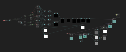
are sticky notes really the only way to document nodes in the shader graph? Stuff is starting to look like spaghetti and I want to organize better...
this group is very inactive... anyone knows a better place ?
You're honestly better off doing what you said you don't want to do...read the docs and google for it.
BUT...
Basically, the post processing (varies by pipeline), draws a full screen quad and does a blit passing in the current image as _MainTex, and you output your corrected-image in your pixel shader.
The docs were clear enough really, but I didn't see any examples there which is unfortunate, because I'll not be testing what I've learnt for some time , so I can't brute force codes to see what's the right way. And being no examples online, I guess the only option is personal help , which Im very disappointed to say that Shaders seem to have a very poor community...
Though maybe it's because coders are turning into visual graphers generally and not just in shader world
Maybe, instead of telling us how much we suck, just ask about how to do the PP effect that you want to do? And maybe mention what pipeline you're doing it in. And have patience and see if you get a reply? Just an thought.
have any of you come accross an issue with Shadows when you use matrix to displace objects based on their position relative to the camera?
I guess you saw my comment as an insult, which I can assure you it wasn't. you saw it in a way it was not intended to be seen.
no, you guys are awesome ! I didn't mean you , I meant all shader coders in general. and it's a fact. this category of people have less active community than other languages
( i've asked my PP question in Reddit+here+Telegram and have't gotten an answer thus far... )
my question though was "how to use a shader as post processing". I'm not looking for a way to write PP. I'm looking for a way to apply it to screen. I know the shader part, now I'm asking about the C# part :D
Hrmm, wasn't able to find a solution anywhere online... is it not possible to make a wireframe shader using shader graph? (HDRP)
Is there a way to make the darker a color it gets replaced with just less alpha value?
For something like with noise
Hi, i'm trying to learn shader coding and cant find any good and free vs plugins. Does anyone know a good one?
What do you mean?
I'm looking for a auto complete and syntax highlighting plugin for visual studio
Wait for shader or just plain visual studio?
set the alpha to the r g or b value
shaders
hmm I'm really sorry but I don't know any!
do you just code without that stuff?
yes I use URP shader graph which is very nice
ohh
@granite violet does it work?
let me see
What Pipeline are you using?
No, I just makes the white part a little blinding.
I think this should work

Oh cool!
Thank you!
oh wait
for some reason I don't have PBR so the names are a little different

Is alpha emission?
I'm not sure what your question is here.
If you want to darken a particular shade/color, you multiply the entire RGB vector (a float3) by some value less than 1.0.
So to cut it in half, multiply it by 0.5....but there's gamma correction unless you're in linear color space. But anyway, just reduce it by some fraction.
The alpha is more about how that color will blend with the underlying color.
*below Ambient Occlusion
well I think I jumped to conclusions. I want to have it so that the "blacker" a color is the more invisible it is.
built-in. but out of curiosity, can we write shaders for other pipelines too ? I mean properly
@granite violet Is this what you want?

I just tried this. I just made my plane I had the shader attached to one color that was my (Color) variable
OK, it's all math. Because colors are numbers (mixes of R, G, B) right?
So you can "invent" any method you want. You can calc the "luminosity" of the color. I think there's macros for that to convert to B&W color, in several if not all pipelines. It's some differening values, since the human eye is more sensitive to green than to other colors.
Then once you get the luminosity, you can use that for the alpha.
A simple way is to use the max() functions to take the max of RGB and use that has the "brightest pixel".
So float myAlpha = max(max(color.r, color.g,), color.b);
Well I think I should have said. I want clouds I thought this could be a way to do it
Yes, they can all (theoretically) be written by hand, without using a graph. Not well documented though, yet. @empty oar has a guide and so do others, somewhere.
https://www.cyanilux.com/tutorials/urp-shader-code/
Explains how shader code (ShaderLab & HLSL) is written to support the Universal RP
ah , that's good to know
I've heard there's full of #include and very nasty code designing needed
but as long as it works.. .who cares...
You're traveling in the bleeding edge of the road-less-traveled (shader programming).
Shaders are great, but as you've noted, it's a rarer art, and a sort of black-art with secrets and hard-to-initially-understand hardware lurking inside the computer. A basically separate specialized computer inside another computer.
Unity is undertaking a new path, and it's not well documented or refined yet. So with SRP's (URP or HDRP), you're going to have to dig in a lot and figure it out.
If that frustrates you, the standard pipeline will be around for quite a while I'd predict. And it has much more documentation and support/tutorials.
Frankly, if you can do it in URP (and mostly for HDRP too) you can still pull it off in the standard pipeline. With HDRP in particular, there's more....options and techniques....exposed in the new pipelines as they reinvent things. But for URP, you can do most of that in standard no problem. And Shader Graph is porting to, or has been ported to, standard too. A few things are different, like how it batches materials, and some volume things, and multi-pass options. But mostly, you can work around that stuff if you want.
It's all up to you.
Thanks . I sure as heck want to learn hdrp and urp, it's all very weirdly are lovely, you just can't give up coding after you make your own's first specular+Lambert shader !
Anyone had experience with resolving frame lag / hitches the first time visual effects play on device? after the first time they play fine. 2019/URP. Thinking its probably shaders but its not practical to preload all from a shader variant collection, or practical to use the warm all shaders call. I thinking it might be possible to build a collection on the fly with to warm just the shaders needed. But there doesnt seem to be an easy way to identify these from a Visual effect asset at runtime.

I just finished making a shader. How do I use it in my project?
you attach it to a material and then put the material on whatever you want

in the project tab you can drag the shader onto the material asset
you can also near the top select your shader from the drop-down list in the material in the inspector

Hey guys (new to shaders), im trying to create a basic grass shader (URP shader graph), and so far it's working great, but i would like my grass to render in a lot lower draw distance than everything else - would you do that inside the grass shader? I tried an overlay camera that would render just the grass, but that didn't work cause the camera was obviously rendering the grass over everything else.
Do you have an idea how to solve it?

I can't get something like this to show on shader graph ever
also my main preview shows a pink color no matter what alternations I try
Make sure your render pipeline is set up for the shader type. (Like for URP, or HDRP).
https://docs.unity3d.com/Manual/srp-setting-render-pipeline-asset.html
Secondly, make sure you're using a sprite if you have a sprite lit master node.

Often hidden behind a loading screen or some other splash screen.
How do you exactly,
use
that?
Fr tho im sorry how do you call this function? I added
using UnityEngine.Experimental.Rendering.Universal;```
but cant really just WarmupShader([args]); in StartI used URP (you install it and then create a render pipeline asset) and then you go into Graph Inspector in shader graph, click the plus, then URP and it adds it in. Presumably the same goes for other pipelines but i haven't used them yet
are there ways to load specific textures into VRAM ?
/unload them
for as long until i unload them that is
and then id need the ability to keep them in there

for a 2D game using unlit sprites, which option would be best?

I used a forward renderer and my sprite finally changed colors
Yeah, because SG expected that you were using an SRP (like URP).
So now you get to debug it.... 😉
Unless it is supposed to be black.
how do I debug it?
Well, usually you output information in a color....
But anyway. What SHOULD it look like?
What are you doing? Show whole graph.

Note that the sprite renderer makes a mesh for the sprite and it puts the color into the VERTEX COLOR of the mesh.
OK, so start by simplifying.
Just do the texture read part. Forget the stuff to the left (disconnect it). Read the texture at the UV and output the result to the color.
Don't forget to press the save button (don't use Ctrl-S it won't work).


Yep. Does it work?

it works but it looks weird
the top is cut off a bit
and the image quality is lower
Huh. Might be the sprite renderer's setup??????
What resolution is the texture in/at?
where can I check the resolution of a texture?
Check import settings
and the texture itself (click on it and check the inspector)
I don't have a texture item, I only have a material, a sprite unlit shader graph, and my pipeline
Uh, something is mapped to MainTex...input variable on your shader, right?

It's a yellow circle with black border that has "play game". That's the texture. What resolution is it?
In your assets.

Yeah, it won't clip that off due to the change.

I don't do sprites much, but you can try the sprite editor too.
Anyway, it cannot tell about the black border that way unless by alpha.
So you could clip alpha zero maybe?
how can I do this?
But find the yellow circle texture and check that resolution and import settings.
Hang on for that next alpha part.
is the yellow circle referring to the play game button?
Sure. There

without the current render pipeline, the resolution is fine
See the filter mode? You have it on point.
Try another mode
actually its not the pipeline, it's the texture after all
wait
i meant my material*
It has zero alpha too, so we can tell unity to clip it, or clip it our self.
the image renders ok but the material makes it look like that
Well, you're using point filtering, so it will do that I guess. Depending on what res you're at on screen.
It won't smooth it out.
But then again, you want a pixelated shader, right?
So these things are kind of exclusive.
But let's do it a step at a time.
i don’t think it has to be a sprite

you could just make it a normal texture
i just need a texture that renders the image properly to begin with but can also make a pixelated effect on request
Your shader is currently not using your pixelate logic, right? Just outputting the texture results. Right?
yeah
Change the filter mode yet?
You can also change the sampler state in the shader with a sampler state node.
I tried all 3 filter modes but no difference
Others are commenting, they'll have input.
You're outputting the RGB (Base Color) but not the Alpha. You may need to check the Graph Settings (in Graph Inspector window) and make it Transparent for the port to appear.

ok


it works!
That's the alpha clip.
Which is fine, but we're trying to figure out pixelation. Is that OK now too?
looks good to me
ok
when attaching my pixelate logic, it works
when it reaches maximum, however, it disappears because it's that pixelated
0.99 looks like this

lol

what's 10 %

you're screwed on the text, if it's built into the texture

10%
There's 100 ways.
OK
actually, I'm looking for a pixelate effect that is independent from an image's resolution
the pixelate boxes seem to care about the width being more than the height
Once common way (particularly if you're doing the whole screen) is to do it in a post processing type of pass
OR
BETTER, to render to a lower resolution to begin with, and upscale it. But that can have some drawbacks too.
Or you can sample it in the shader by doing multiple samples with UV maths and averaging them.
or whatever.
I set a certain variable from 200 to 300 and the text issue seems to be fixed
OK, good.
Now, let's assume that you want to render to a lower-res render texture, and then upscale. That may NOT be what you really want, and there's some drawbacks but I don't recall the specifics. But OK, it all depends on what you want.
Rendering to a lower res texture is just plain FASTER, as there's fewer pixels to process and sample. Then, at the end of it all, you upscale the lower res texture to higher res screen.
So how do you make it resolution independent?
With math! (next post).
So you want to make it resolution independent. But you'll have to think about it, since you can have several resolutions and aspect ratios IRL.
So you have have mobile phones that can be (unrotated) taller than they are wide, and "normal" screens that are wider than they are tall, and at al sorts of resolution.
But you want to emulate some kind of look. Say a 800 x 600 screen.
So given your device's (check at runtime, per frame if it can change) resolution you can compute what you draw based on the aspect ratio. Maybe you only want to allow 800 x 600, and mobile users will have to rotate their screen (IDK if that will really work, sounds like wrong aspect ratio, but...).
So you set up a render texture that is 800x600 and render your game to it.
Then at the end it will output that to whatever resolution is running
So it will work on 4K or 8K devices just like it will work on 1920 x 1080 devices.
IIRC.
Others may comment more.
And if you want to mix full-res and pixelated, you'll have to have multiple cameras.
And that's only one way of many.
I'm just giving you ideas, but I'd do some heavy research and think about what your needs really are.
If you guys wanted that in your game, would you just split the meshes into whatever material they used?
So for that you'd have 3 meshes and 3 matierals.
The green part would be one mesh/material (metal painted green)
Stone would be 1 mesh and 1 material (stone mat)
That tin/metal part at the back would be it's own mesh and matierial
Or would you have the same material for the green and silver parts but change the colour property since they're pretty similar?

Hey. Is it the ideal way to keep all the post pro inside OnRenderImage ? ( Built in )
Or is there other useful methods as well ?
Hey there, I need to fade between two albedo textures on a material (or alternatively two materials). Is there a way I could possibly do this without writing a shader? Thank you 🙂
is there a more stable way to get world position in HLSL for screen space effect? It looks good upclose but going further destroys it (camera clip does not change a thing)

Got it fixed, was passing linearEyeDepth but needed default one
I like the separate mesh/material idea....because they ARE separate (just bolted together). The result of the lighting is that the painted surfaces will have different characteristics than the metallic ones. So you'll set the material values separately.
The GPU doesn't care that they're different meshes...make a prefab.
Now, there's implications in terms of things like colliders...you'll have to think about that and decide if the objects can share a collider somehow. But other than that, it is more flexible to have them be different if they're different.
It's all triangles and draw calls in the end. If you have 100 different materials on one "object" that can get excessive, but otherwise...meh...make your life easy.
But you can, of course, use things like metallic maps/gloss maps and such per pixel, even in the standard shaders. It's a lot of texture authoring, and is often done using higher-end software, and it's more work.
I am trying to create a custom node in shadergraph, The intention is to take in a Texture2DArray, loop through all the textures, combine the colors based on the alpha and the result is the final color. I have basically no experience in writing shaders so is this sort of thing possible or am i taking the wrong approach?
this is the sort of thing i'm trying to achieve
fixed4 result;

for (int i = 0; i < Texture2DArray.length(); i++)
{
     fixed4 texCol = UNITY_SAMPLE_TEX2DARRAY(Texture2DArray[i], UV);
     result = lerp(result, texCol, texCol.a);
}

Output = result;

Given that code, I don't think so. Depends on what you mean by "combine the colors based on the alpha".
If you want to BLEND them, you'd
- first initialize result to zero (or ones or whatever) to make damn sure it is initialized, don't trust shader compilers to initialize things. You only need a float3 really, since the resulting alpha makes no sense.
- read the color at the texture & index into a float4.
- BLEND the color manually into your float3 result.
The blend equation for a normal transparent blend is:
(given that result is the accumulated color, and source is the current pixel value)
result = result * (1-source.a) + source.rgb * source.a;
This is assuming you blend OVER TOP of the colors. In other words that blend is an over-blend. But you may actually need your loop to run backwards, starting with the highest index if that is the "deepest" color, and blending to the lower index of 0. All depends on how the 3D is ordered.
Incidentally, that "over" operation is also why transparents get drawn by the engine in back-to-front order. 😉
will try it with these changes thanks for the help 🙂

First guess, without seeing your shader....
Check both the resolution of the textures you're using, and of the mesh you're mapping the results to.
I am not using a texture, I am using a gradient.
here it is:

Do you know why all my textures are pink?

Not that i know of
If you make a new material, is it pink too?


That shader still says "Standard". (Bottom pic).
https://docs.unity3d.com/Packages/com.unity.render-pipelines.universal@11.0/manual/upgrading-your-shaders.html
hey there,
im struggeling with unity´s post process effects. If I add for example bloom , the whole scene (+the UI) gets the effect. How can I add bloom or Vignette only to one, specific object?
When using Spine what in our shader causes the alpha to multiple like this? Making it so you can see parts overlapping?
We want the alpha to not see through to other body parts, hope that makes sense. Not sure what we're doing wrong.
Any advice would be really appreciated, @me if you have any ideas!

if you change the transparent tag in the shader to opaque that might fix your problem
it's something like { "RenderType"="Opaque" } near the top
wouldn't that disable transparency completely? We do want transparency but just so it doesn't show the parts overlapping. Might have to resort to render textures but that's a last resort.
oh i see
in that case maybe you're multiplying some values in your fragment shader where you should be adding them?
i'm not sure if you can do what you're trying to do simply
hmm okay thanks :)
Anyone know if there's a way to embed a Texture 2d Array Asset directly into a material?
Everything I read online seems to suggest this array can only be assigned to a material via a C# script attached to the gameobject
makes it hard to test a shadergraph without being able to drop in a test texture array
Texture2DArrays can only be created using C#, but you can save it as an asset and should be able to assign it on the material like any other texture, assuming the property is exposed. I've got a small tool here for creating the asset from regular textures : https://gist.github.com/Cyanilux/e672f328c4cafb361b490a5943c1c211. Or can use this : https://github.com/pschraut/UnityTexture2DArrayImportPipeline
Hey guys, I'm trying to make a 2d water wave shader using a sin wave for now but it seems that whatever I do in shader graph I always get this result in the game. Can anybody help me? I'm kind of a noob with shaders :/


@regal stag Man, awesome. Thank you!
Subtracting the object's position shifts the origin of the coordinates back to 0, it only translates though. There's still scaling and rotation applied. The Position port expects Object space, so is now applying that scaling/rotation of the object twice.
To get the vertices to match the selection outline, you'd just use the Position node in Object space. Or, if you really need to work in world space, use the Transform node to transform back to Object before inputting into the port.
Research "alpha clipping" in the opaque queue. 😉
Ty
Looks like a scaling issue maybe, using the X axis from the UV might work better for the Sine input. Or increase the multiplier a lot to increase the wave frequency in the scene view.
@regal stag I tried it already but it doesn't seem to work. It gives me the same result. Is the problem maybe the fact that I'm using a sprite renderer?

Also, if you're using SG, it has an alpha clip threshold you can use.
All I did was replace the Position node with UV
You don't want to replace the Position entirely with the UV. Just the input going into the Multiply (then Sine)

Might be because you're now using World space for the position instead of Object?
I feel dumb ahah yes, I replaced it but I have the same result. I found something tho, when I modify the multiply value, the curve changes, just like if I was getting a different part of the sine wave

That's a little weird. Multiplying should adjust the scale/frequency of the wave, not shift it
What happens if you change the value to like 500 or something higher?
exactly that's why i'm soo confused ahah

Same code but the value of the multiply is at 500
Yeah I'm confused too. Maybe try a regular quad/plane instead of a sprite
Same problem but I think I found something. Look what happen when I put it on a plane

Maybe I'm not using the right axis? Or should I even modify the vertex shader?
Oh right, the sprite is a quad. It doesn't have enough vertices to offset in order to show the shape produced by the wave
It might be better to just alpha clip parts away to produce the wave shape, so it's all in the fragment part. You could use vertex displacement but you'd need lots of vertices to make it look smooth.
OMG yesss that's why I have only 4 vertices, how can it make a sine wave -_- thank you soo much, I think making it in the fragment shader is a better idea and I can just modify the alpha like you said. Thank you sooo much!
Yeah, should be a similar setup. You'll probably also want to Multiply after the Sine to adjust the amplitude/height of the wave.
Yeah, I plan on using a compute shader in the future for now I just wanted to test a bit and have something to prototype with that doesn't look boring
is there something specific i have to name my mainTexture for it to be accessible through script?
I am using URP with shader graph
i tried _MainTex

Thanks man
You need to change the Reference of the property, not just the name used for display. It's under the Node Settings tab of the Graph Inspector (while property is selected).
@regal stag thank you, that fixed it
and what should i switch it too?
Upgrade the materials. Unity will auto-upgrade the standard shader to the URP lit shader for you, if you ask it to.
Yeah but how do I upgrade them?
(sorry for being a bit foolish but I am only a beginner )
Read the link, it has instructions in it.
    Open your Project in Unity, and go to Edit > Render Pipeline > Universal Render Pipeline.
    According to your needs, select either Upgrade Project Materials to URP Materials or Upgrade Selected Materials to URP Materials.

Note: These changes cannot be undone. Backup your Project before you upgrade it.

Tip: If the Preview thumbnails in Project View are incorrect after you've upgraded, try right-clicking anywhere in the Project View window and selecting Reimport All.```
How can I take the Out(4) and put it in an In(4) or something and output 4 elements or something
or basically just take the Out(4) and put it into the Vector4
thanks... Oh true I am blind x)

around the middle, I take my UV node and I multiply it by another vector4. This allows me to successfully scale my texture properly. However, a problem arises when a black-looking pillar forms above my texture. Why does this problem occur?

It's already a Vector4, so you shouldn't need to do that.
float4 = vector4
how can I turn this from a square view to its own dimensions
it's originally a 592x128 image
but shader graph wants to make it into a square

when I pixelate the actual image, the pixelation is slanted
https://godotforums.org/discussion/25882/make-shader-shape-independant-from-texture-size
might help. You'll need to interpret for your use-case.
How much of a performance issue (or non-issue) is setting material properties during runtime?
Minimal to none, most of the time. If you're cloning materials every frame it could have some overhead and GC, but otherwise, it has properties anyway, and they get sent to the GPU anyway...??every frame??. (might have some type of cache so...) So the set time % of the whole process should be fairly minimal. C# has to find the material in memory and set the variables. But some of that is asynchronous to the drawing going on.
If you have 100,000 items to set, you'll probably want to be more picky. So how many items do you need to set?
Best Guess.


Ah alright, I didn't know they get sent every frame, I assumed it worked differently. Thanks!
It says ComputeGrabScreenPos is also undeclared which is what I think I wanna use but neither is working
There might be some caching on the GPU side, managed by the engine, but I wouldn't count on it being there anyway. That's pretty tech-deep for me.
Overall, it will depend on the "how many" part.
More than a few, less than a lot :)
lol
I wouldn't worry too much. Cache the references on the C# side for speed if you can.
And use the propertyID values, not names.
keep the C# side as fast as possible and let the engine do its thing.
I was using constant strings, but I guess I can change them to property IDs. Thanks!
Yeah, people don't realize it, but IIRC, using strings causes a lookup to get the ID anyway. So you may as well get the ID once, in startup, and cache it, rather than do it every iteration.
I hate to do this but anybody know what is going on with my issue 😬😁
IDK, should work. This:
https://docs.unity3d.com/Manual/SL-BuiltinFunctions.html
claims such exists. Are you missing an include or something?
OH
that might be it
what do I include
hmm seems like nothing needs to be included? is that even a thing for shaders?
ok lemme try just doing "#include "UnityCG.cginc"
siiick I worked thank you
Hello, I am new to shaders. Basically what I wanna do is I have 2 textures - lets say a triangle and circle. They both have transparent background. I want to place one above the other, as if it were 2 layers in photoshop. How can I achieve that? I tried blend node, but it mostly offers some subtractions etc. Would anybody know? 🙂
use lerp node, A is triangle,B is circle, lerp by the alpha of circle
Hmm, it doesnt seem to work, it just translates from one texture to other depending on the W attribute of T input... 😦
Anyone know how to use delta time node in shadergraph?
Whenever I use it I get weird twitching instead of beautiful framerate independant math as I would get in c# logic
Getting these weird seams, which I suspect have to do with a lack of proper use of deltaTime
why is this using delta time instead of just Time?
it's not, it's using time, and a bunch of other other things, but not deltaTime
The issue looks to just be some poor logic somewhere causing it to not tile properly
delta time is not relevant to this
Hm, okay. Poor logic is pretty much guaranteed, I have little to no clue what I'm actually doing here
trying to get a water wobble effect going on but I'm pretty much just trying random math that feels like it's going in the right direction
If I were looking for someone to rewrite an SRP shader into an HDRP version of the same shader for a flat fee where would I look.
I guess
Blend One One
Would exactly be the Photoshop Normal effect ?
There's here and there's the official reddit, I think that's pretty much it for Unity shaders community
( If there's more, let me know too. Tnx)
You could make like 4 steps of fade texture from texture A and texture B . Then apply them to the albedo by some speed u want. But blending smoothly requires shader code
That's a smarter idea than I thought actually. I managed to get it working by cheating; I put two of the same object in the same position and then adjusted the alpha, but I will definitely do this next time if needed! Thanks 🙂
@proper dew yeah that should work too , pretty hacky way :D
Hacky for sure but it works 😂
is there like a specific person i should hit up or?
@wispy stump I don't know them much tbh
Hey folks, anyone familiar with Unity shaders available for a qq?
Struggling to pass extra data into my surface shader 😫
You should spell it out, so people can reply. In other words, "just ask, with specifics".
I'm passing contextual data for a mesh's vertices into a surface shader through its uv2...uv5 fields
But haven't been able to discover (online or through experimentation) how to access it in the shader
I see there are TEXCOORD...TEXCOORD3, but those are a differrent data type than the uv...uv5 data that I'm passing in (former is float4, latter is float2). So, does mean that uv3 and uv4 data are both packed into TEXCOORD1?
Just not understanding what happens to my UV data when it goes into the surface shader.
https://docs.unity3d.com/Manual/SL-VertexProgramInputs.html covers some of this, but doesn't mention what happens to uv5+ when it gets into the shader. It also actually adds some ambiguity about the data type for TEXCOORD properties... my intellisense says they are float4, but the docs say they could be float2, float3, or float4 without stating why 😦
Define it has a float4, and pack it yourself, if you want it packed.
But in the end, you should be able to define your surface input struct to have uv0, uv1, uv2.... as float4's if you're packing them. You can define them as float2, 3 or 4's but I'd pack them myself and use float4.
See note that the bottom, here:
https://docs.unity3d.com/Manual/SL-VertexProgramInputs.html
lol
same link on edit
It figures it all out. Use float4, pack it yourself, unpack it yourself, you'll save some headaches.
Watch out, though, since some UV's are used for light mapping.
Oh... intellisense shows me this about Mesh.uv
public Vector2[] uv { ... }
And I said float2 above when I meant Vector2, oops
When you say "pack it yourself", I'm guessing you mean something like this?:
mesh.uv2 = new Vector4[size]{...}
OK, the packing I'm thinking of happens between the vertex stage and the fragment stage IN THE SHADER.
as for Unity's define of mesh data, it is what it is.
I'm running out of time, have to bail out, but you can figure it out.
Since they define it as an array, maybe you can use any of Vect2, 3, or 4.
You get up to 8 UV's in a mesh. Sorry I can't help more right now.
"OK, the packing I'm thinking of happens between the vertex stage and the fragment stage IN THE SHADER."
Gotcha, yes I am doing this now actually to get the vertex data into the bit which calculates the pixel/fragment color.
"I'm running out of time, have to bail out"
No worries and thanks for your help. I see that I get up to 8 UVs in a mesh, but I guess I need to keep putzing around in the shader to see how that data actually ends up in the data structures there
I feel like it should be MUCH easier to send data into a shader! Feels like I'm cutting up pillows, packing them into lunchboxes, mailing them somewhere and then trying to stitch them back together in the correct order 😩 Is this only hard because I'm using a surface shader? Maybe I need to go with a fragment shader instead...
Burned out for today, but posted on the forums... hopefully someone can help 🙂 https://forum.unity.com/threads/confusion-while-passing-arbitrary-data-to-surface-shader-via-vertex-uvs.1160381/
Unity Forum
According to docs, UV data is available in surface shaders through the TEXCOORD0...TEXCOORD3 fields:
"TEXCOORD1, TEXCOORD2 and TEXCOORD3 are the...
I think if you send in via .uv/.uv2/etc they are always set to Vector2 (which corresponds to float2 in shader. But you could write float4 still and the z and w channels will likely be filled with 0.
In the Mesh class there's a SetUVs function iirc, which can pass up to Vector4 so can fill those extra channels.
Ah thanks for this, I'll give that a shot in the morning 🙂
So, tex2D uses a normalized 0-1 value for texture coordinates right?
Is there an obvious way to sort Sub Graph input orders that I missed? They are all grouped and sorted on my Blackboard, but on the Sub Graph node's UI, the input order is stuck with the chronological order of the creation of new properties. 🤔 (version 2021.2.0b7)
Yes, though the coordinates can be outside that range and the texture will clamp/repeat/mirror depending on the wrap mode set
yeah thanks, just making sure as i'm having issues finding the real problem.
How can I not include a layer in the depth texture?
Because the regular shaderlab syntax doesn't have a proper type for vector 2 and 3. This is fixed in more recent versions of shadergraph
thx
anybody know if there is a way to get the index of the character in a text shader

I got the text to do a kinda float thing but I want each letter to be independant
Hello again. I still have problem with shadergraph. I was asking yesterday and I was sugested to use blend with overwrite to combine two textures to work as layers in any photoshop-like program. Blend node seems to have some problems with alpha overlapping. I tested it out and here you can see what happened:
I created blue and red line and I want to place them one on top of the other (for test purposes, my real issue is more complicated) using shadergraph. Both lines are blurred so their edges are semi-transparent. When I place them on top of each other in krita (or photoshop), they are working as expected. But if I place them on top of each other in shadergraph using blend overwrite, the red one has weird blue outline.
I am using this for 2D game, so all textures are 2D images and the texture is 2D unlit - in case it matters. Also notice the textures are not displayed incorrectly in the graph untill it reaches the master node.


So to my surprise extra blend node fixed it. It seems like a problem with the texture sample or something... O.o
Still looks like some performence slow down to me.
hello. Do you know any good tutorial(or any document/script) for Compute shaders... I have never worked with shaders before and im little confused. I need to create mesh with Compute shader. Ty 🙂
Well, you could start with reading the Unity documentation on procedural geometry, specifically DrawProcedural and DrawProceduralIndirect.
But you're jumping into the deep-end without a life jacket, if you have never worked with shaders before.
https://docs.unity3d.com/ScriptReference/Graphics.DrawProceduralIndirect.html
@meager pelican yea i know... but i dont know other method (some api) to put my vertices/indices into buffers and create mesh by GPU not CPU ... :/ (need smoothy but with big amount of vertices)
Is it possible create mesh by shadergraph? Or it's only for textures?
@vernal island if you need to create a mesh during runtime you have to do it in a monobehaviour
You can create procedural geometry in the GPU. Here's an example: https://github.com/keijiro/NoiseBall3
It's only for visual effects of course, not game logic
Ah ok :/
Ok ty! :3
Hey guys anyone know why I'd get this error when trying to use texture arrays in hlsl? unrecognized identifier 'TEXTURE2D_ARRAY' at line 39 (on d3d11)
I can't find any documentation on the subject unfortunately
Do I need to add some kind of include?
Your suggestion was spot-on, thanks! Some additional details here: https://forum.unity.com/threads/confusion-while-passing-arbitrary-data-to-surface-shader-via-vertex-uvs.1160381/#post-7443542
Unity Forum
According to docs, UV data is available in surface shaders through the TEXCOORD0...TEXCOORD3 fields:
"TEXCOORD1, TEXCOORD2 and TEXCOORD3 are the...
@meager pelican Thx for your help, too! ^ link clarifies some of the stuff we were poking at.
I don't know, but it sounds like either you've written some invalid code, there's a compatibility issue, or there's a shader code-gen issue to me. I'd start by making sure my own code looks reasonable, then explore the possibility that what I'm doing isn't supported for the hardware I'm targeting (check your pragmas) and that there aren't any known-issues related to shader code generation (e.g. specific variable names to use or avoid)
There it is! Tucked away behind the older mesh.uv stuff!
https://docs.unity3d.com/2021.1/Documentation/ScriptReference/Mesh.SetUVs.html
Thanks for the link, mannyhams and @regal stag
It can take float2, 3, 4...!!
bglous (the walking Unity documentation phenom) does it again.
Ya bgolus is incredible
is texture sampling costs only for UV bounds? If I have a 4k texture, which I want to use half of it, does that mean would that cost like sampling 2k texture?
I doubt it is as simple as the "uv bounds" since there's a memory cache and accessing going on. But it might be able to 'skip' a significant portion of memory access.
And the results may vary by hardware implementation, so YMMV.
In general, the memory cache should "read ahead" for sequential access a bit, but at the end of your X uv, when it gets to .5, you'll increment the y and then start over with x=0, so you've "wasted" some read-ahead, and you've cause another cache miss to jump to the next area in memory.
I think. 😉
In the end, there's not much you can do about it, if you're using a texture atlas, which is still going to be better than two (or 4 or whatever) different textures. At least it has a hold on the thing, even if there's cache misses.
2 cents.
@tired crown Indeed, the blend node isn't exactly how photoshop handles layer blending, I think it only works with the color, ignoring the "layer opacity"
I implemented the math of the "over" operator described here : https://en.wikipedia.org/wiki/Alpha_compositing#Description
It seems to be what your are looking for :

@meager pelican is texture atlas still more performant for mobile devices?
I find the program here is making mesh w/o mesh datas. (I have data of vertices and indices. But I would like to make mesh without that indices... Because the XNA output is buggy little bit for indices) don't you know any good "tutorial" same as this one? 
How do i change the strength/color of specular from my water shader?
There is an option for specular color but either it makes the water look weird and a bit pink when i set it nearer to white, or the reflections are super bright blue
at least, the reflections of the sky
Actually nvm I will try to use a gradient input for the specular color
Cool cool thanks I'll confirm all of that after work
Trying to convert my shader graph shaders to written shaders but it's much more difficult than I thought
Came across a Unity rendering bug and wanted to share it here to make sure people are aware when creating their graphics!
CustomRenderTextures don't update on WebGL if doubleBuffered is enabled. You can find this on Issue Tracker here: https://issuetracker.unity3d.com/issues/webgl-customrendertexture-is-not-updated-when-double-buffered-is-enabled
Fingers crossed the QA team prioritizes this higher in their next triage. This is a massive issue for my team; I imagine it affects many others developing for clients on WebGL as well.
How to reproduce: 1. Open the user's attached "CRT WebGL Bug" project 2. Open the "Demo" Scene 3. Open the Build Settings (File->...
guys when importing game asset my material order is kinda hell

but in blender it is fine. I export as fbx model

pls don't ask me to show the code for this🤦♂️
is there any info on what this function does? unity docs should show this stuff.

Whoa, really good job! This seems to work! I still find some small issues, but I guess I just need to fix the textures. Thank you very much, you saved me! 🤩 👏 Though I am surprised such trivial task requires so much effort.
hi, im using this grass shader and modifying it to have the grass spawned through code:
https://www.patreon.com/posts/urp-compute-54164790
This is a simple function i adapted from the code and put it on top of the grassPainter script:
public void AddPoint(Vector3 grassPosition, Vector3 grassNormal)
    {
        positions.Add((grassPosition));
        indicies.Add(i);
        length.Add(new Vector2(sizeWidth, sizeLength));
        colors.Add(new Color(AdjustedColor.r + (Random.Range(0, 1.0f) * rangeR), AdjustedColor.g + (Random.Range(0, 1.0f) * rangeG), AdjustedColor.b + (Random.Range(0, 1.0f) * rangeB), 1));
        normals.Add(grassNormal);
        i++;
        print(grassPosition + " | " + grassNormal);

        mesh = new Mesh();
        mesh.SetVertices(positions);
        indi = indicies.ToArray();
        mesh.SetIndices(indi, MeshTopology.Points, 0);
        mesh.SetUVs(0, length);
        mesh.SetColors(colors);
        mesh.SetNormals(normals);
        filter.mesh = mesh;
    }
I'm calling it using this:
for (int x = 0; x < 50; x++)
            {
                for (int z = 0; z < 50; z++)
                {
                    grassPainter.AddPoint(new Vector3(x, 0.9f, z), new Vector3(0, 1, 0));
                }
            }
Now if i see the i of the grass spawned in the grass painter, i do see the number increasing. but no grass appears in the scene and game view. does anybody know what's going on?
hey i have a very basic shader but theres these lines that appear near the edges of the sprite, not sure whats causing these, does anyone have an idea ?

The horizontal and vertical lines in the sample texture node ? This is just because the node preview doesn't display transparency
Can you show the rest of the graph and the current result ?


Well, you didn't connect anything to the alpha output => no transparency
ahhh didnt know i had to do that
thanks!
also, any idea why changing my frame value would tank my framerate ? im dropping from 500 to about 80 ?
I don't see a reason for this
well now it doesnt anymore either way. strange
my unity keeps freezing when there is 2 enabled reflection probes is there a fix for this?
Ideas on how to create a trail that stays same size no matter the distance from camera? I want to create a tracer effect similiar to this:
https://www.youtube.com/watch?v=AYGS3_Vyxys
Currently im using a VFX graph with screen space size set to 5 pixels, but this solution is flickering very strongly for some reason:


Cell phone footage captured colorful scenes in the night sky over Nangan in Taiwan’s Matsu Islands on Thursday evening. But these sparks are not fireworks but tracer rounds from anti-aircraft machine guns.
They're great for batching, because they can share the same material but with different instance offsets for texture data. IIUC.
But has far as memory goes, bgolus to the rescue again:
https://forum.unity.com/threads/potential-consequences-when-using-texture-atlasing-and-very-large-textures-on-mobile.730130/
Unity Forum
Hi, right now I am using 8k texture atlases to atlas 64 different 1k texture meshes. I'm targeting mobile. While this reduces my Set Pass count to 1,...
Other hints (including using fewer materials by using an atlas):
https://docs.unity3d.com/Manual/OptimizingGraphicsPerformance.html
If anybodys wondering - this does the job:

hello everybody, I started to study shader graph, and Im having some trouble to make vertex displacement, on the new version of shader graph
i made some subgraphs for distortion, outputing a vector 4 (RGBA)
and I multiplied them to have a single input source
however
it doesnt seem to be accepted by the vertex position
could anybody give me a hint on what am I missing?
please
So if tex2D uses a UV value of 0-1 to grab a color, how come I can use UnityObjectToClipPos(v.vertex); to get a value between -1 to 1 yet get a properly rendered texture when divided by _ScreenParams.xy? Wouldn't that be a -1/1920 on the left side? it even works with a clamped texture.
if it's clamped will it simply cull the -1 to 0 and stretch the texture on its own?
i'm so confused right now 😆
i would have assumed a clamped texture would get rendered on half the screen or something. but how and where is this done then? because i'm having big trouble using UnityObjectToClipPos(v.vertex) for mathematics right now
Hello. I want to ask. If i want to create mesh by computeshader and I have vertices (indices too but buggy), I need to write something in shader? If I understand it well (I hope), I need to push data to GPU buffer and after that take it and use drawprocedural and if I will do something with the model I have to write a code in shader right? (Drawprocedural doesn't need indexbuffer to create triangles alone right?)
And I have one question, I linked buffer with "shader" buffer and I wanted to call setdata but unity debugger tells me I set data of bigger amount of data (I need put 4M Bytes).
It's a problem with set or the buffer in GPU can't handle this amount? (If call setdata more times or GPU memory size problem)
Does anyone have any idea why a custom shader graph might not show up under the materials menu?
Got it working. Was in "failed to compile." Turns out there were some typos in a custom function. All fixed now.
Hi, I'm new to shaders - I created a simple one which I use to apply a RenderTexture to a MeshRenderer ingame. I implemented two passes so that the back face is flipped to have the texture be right way around on both sides (Probably not related, thought I'd mention regardless).
My issue now is that this works perfectly fine as is - But in VR, the right eye is misaligned.
If I use the builtin Hidden/BlitCopyWithDepth shader instead of my own one, it works fine in VR but has its own issues (Depth, Not flipped on backside, etc). To try and debug this I grabbed the source of this shader and compiled it myself, but that results in the same bevahiour as my own shader where the right eye is misaligned.
Obviously, I have to be missing something - If somebody could hint me what it is that would be appreciated. Here's my shader in question: https://github.com/kinsi55/CS_BeatSaber_Camera2/blob/77fd58eb21dca77266970a618c54aa0ec47d33a6/Shaders/VolumetricBlit.shader
And right as I write that I find out about UnityStereoScreenSpaceUVAdjust - Well, for anyone possibly encountering the same, heres the fix: https://github.com/kinsi55/CS_BeatSaber_Camera2/commit/ba76543db3faf88be764ebcdcbefcfdf8602c3a0
If you're trying to map a texture to the screen, the correct way to achieve that is by using
// Vertex shader
clipPos = UnityObjectToClipPos(v.vertex);
screenPos = ComputeScreenPos(clipPos);

// Fragment shader
float2 uv = screenPos.xy / screenPos.w;
clipPos is in a [-w, w] range (where w is it's 4th component). ComputeScreenPos basically remaps it to [0,w]. We then divide by w in the fragment stage to reach a [0,1] range across the whole screen. If you only want part of the screen you can remap further from here.
If a port won't connect it's because it uses fragment-only nodes for a vertex stage input. (e.g. Sample Texture 2D cannot be used in the vertex stage, but Sample Texture 2D LOD can)
This might give some hints : https://andrewgotow.com/2018/09/09/interior-mapping-part-2/
Hey guys, having a small issue with HLSL so Im not sure if this is a property of HLSL or
if I have this simple code
float3 lightPos = float3(0.5, 0.5, 1);


[numthreads(8,8,1)]
void CSMain (uint3 id : SV_DispatchThreadID)
{
  Result[id.xy] = ((lightPos), 1);
}```Then the output image is black
but if I do this
float3 lightPos = float3(0.5, 0.5, 1);


[numthreads(8,8,1)]
void CSMain (uint3 id : SV_DispatchThreadID)
{
  lightPos = float3(0.5, 0.5, 1);

  Result[id.xy] = ((lightPos), 1);
}```It works
so can HLSL variables not be initialized outside a function?
@regal stag thank you, i'll see if i can do something with this
i think it worked 👍
Hey, I doubt anyone knows but.. does anyone know a good list of fractal distance estimators?
I think global variables in hlsl are marked as "extern" by default, meaning it's an input to the shader and must be set externally. If you want to initalize it in the shader, you may need to mark it as static. (Based on info from the hlsl docs https://docs.microsoft.com/en-us/windows/win32/direct3dhlsl/dx-graphics-hlsl-variable-syntax)
Alternatively could use a macro, #define LIGHT_POS float3(0.5, 0.5, 1);. Then at compile time LIGHT_POS is swapped out. (It doesn't need to be all caps, but that's the naming convention)
OH that makes a lot of sense, thank you so much
I was confused because I needed Pi for skybox rendering
and I was confused why that was intialized successfully
It was because of static const float PI = 3.14159265f;, so that clarifies a lot
Thanks!
I have another logistical problem, though
I'm using HLSL to completely override Unity's camera and render with raymarching
As there is no "list" alternative in HLSL and all arrays have a set size, I dont know how I would pass "Shapes" into the shader
Lets say in my scene I have 4 spheres, how would I pass the info (location and radius) of those spheres into the shader
to allow me to add 1 more at runtime?
Perhaps you have to do it through a compute shader, where you have more flexibility over input buffer shape/size?
This is currently a compute shader
I was more confused about in what form I'd pass shape dat
As an example lets say I have 3 shapes
Sphere, box, torus
Sphere = radius, box = width height and breadth, torus = radius and inner radius
All of these sphers also have an xyz for position
In my non-compute shader attempts at this project I used an abstract class to render every shape
but now Im not so sure how to pass information to have an ambiguous amount and type for each shape
If someone knows how to rewrite a SRP Shader for HDRP I'd be willing to pay someone to do the task.
I'm trying to set the Emission Color+Texture in C#, I can set the Color using mat.SetColor("_EmissionColor", Color.red); What is the parameter for the texture??
Probably _EmissionMap, but it depends on the shader
Do you mean to rewrite a "built-in renderer shader" for HDRP ?
If it's something you got from the asset store, look if the maker of the asset didn't by any chance do a version for HDRP. Else ... well, good luck
It's surprising that not a single person's can do this task its crazy
Does anyone have a pixelate effect shader? Please reply to this message if you have an idea of where to find one as well. I've already searched it up btw.
The pixelate effects you can always find online do the same thing. However, I want a pixelate effect that can do something like this:

however, this is what most pixelate effects in the unity community do:

ew
I can't use that
isn't there anything closer to the first image?
How to make water in URP? All the tutorial on youtube is outdated. I have a river in my game but don't have water so I want to make it look like river water.
@grand jolt realistic water?
Yes
https://www.youtube.com/watch?v=gRq-IdShxpU @grand jolt this should get you started

In this video, we'll take a look at how we can use the Shader Graph feature in Universal Render Pipeline, or URP for short, with Unity to create a water shader! The water shader can be simple or complex, and include the features you desire. Let your imagination get wild in this tutorial, or simply follow step-by-step to get about the same result...


Does anyone have a more in-depth explanation of how the sample texture 2D node works? something is going very wrong and I'm not quite sure why
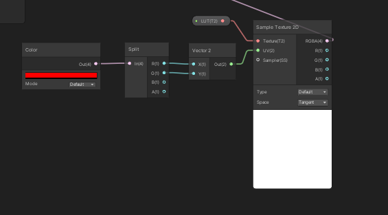
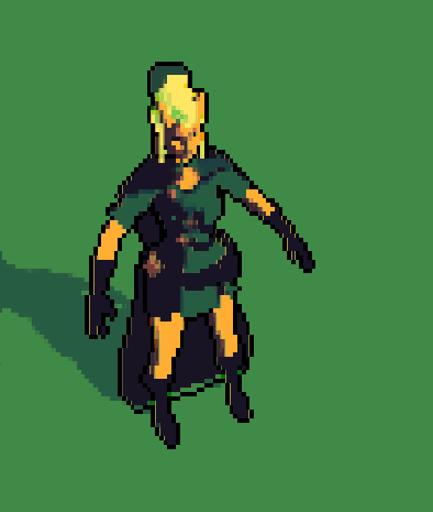
I'm trying to build a palletization system. I have a palette that I used to generate a lookup table (LUT). Basically this maps an RGB position to a color. So what needs to happen is unity needs to read a screen color as a coordinate value (let's just use R and G to make it easy). So say we got R = 10 and G = 255, we need to find that position in the map, X = 10 and Y = 255, and output the color found there.
I built up a shader graph that I would have thought would do that, but instead it outputs colors which don't make any sense.

expected color out: red
result:

You're sampling at the UV position (1,0), so something around the bottom right pixel of the texture. isn't it white ?
Note that depending on the wrapping mode of the texture, this will interpolate with the bottom left pixel
It is red in the texture provided. I think. It should be lol
Wrapping mode is repeat and the interpolation is off so just point not bilinear or anything.
What does your LUT look like ?
Thank you for the help btw. One moment.
Normal and Tanget can be TEXCOORD in fragment input data?
o.normalWorld = normalize(mul(float4(i.normal, 0.0), unity_WorldToObject).xyz);
I have seen some codes like above to compute world normal map. It is a direction not point. It is wrong, right?
This is the LUT I'm using.

the color at 0,64 is what I'm targetting (Y starts at the top and goes to 64, x starts at the left and goes to 4098)
I built the generator so if it needs to be done differently let me know
Y starts at the top and goes to 64
This is in pixel coordinates in photoshop or image editing, in Unity UV space Y starts at the bottom
and X & Y range from 0 to 1
Yep
and 0 to 255 to 0-1 on the X
So the uv you're looking after is 0,0 🙂
Note that you're mentioning RGB value for color, unity alway noarmlizes those to 0-1
So, the red 255,0,0 RGB is 1,0,0 in floating point format (shadergraph vector3)
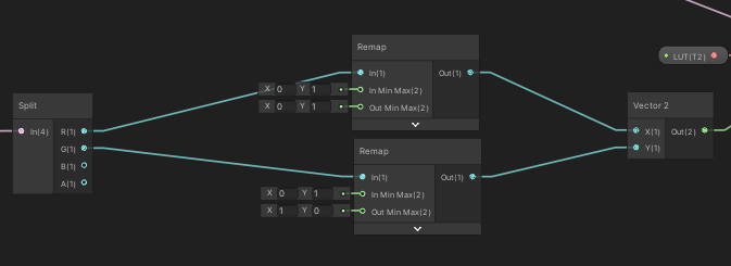
Next, I'd recommand to add a half pixel offset when sampling, you want to sample the center of the pixel, not the "edge".
Instead of remaping to 0;1, remap to 0.5/64 ; 1-(0.5/64) on Y, and similar on X
I'm going to switch to this lut

I'll try that.
ok that's working sir
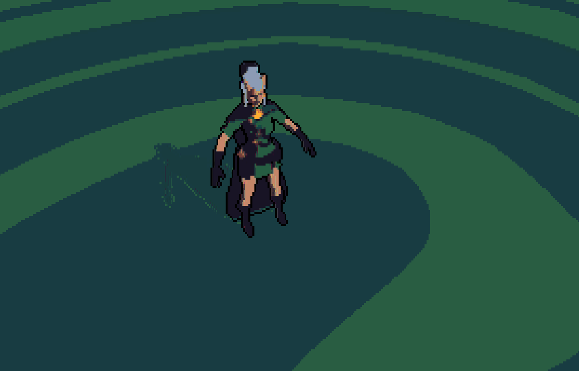
now I just need to re-add the blue aspect lol
https://i.gyazo.com/1795d266521275b5f585eaec2a4d1416.png this is what the asset looks like without blue. So pretty good. there is this odd yellow line coming through at sub-pixel scale though, which is a bit weird.

If you plan to use the 4096x64 texture you posted above, I'd recommand to use it like a 3D texture, it would make the coordinate calculation way easier
Yeah that would be ideal, how do I do that?
In the texture import settings, there is a 3D texture mode 🙂
(unless you have an old-ish version of unity)
And in shadergraph, you use a sample texture 3D node
If you're remapping colors, it's just the matter of taking the input color as coordinate, and plug it in th UV
just have to remap with the half pixel offset, which is even easier since you have a 64x64x64 texture (so no need to remaps the axes separately)
still have the flipped y problem tho

The ... outline ?
no no
look very closely
there are very thin, sub-pixel scale lines that are only on the vertical coordinate
vertical direction*
I was going to say it might be wrapping issue, but the remap should handle that
Thanks for all the help so far btw
How are you applying this effect ?
can I buy you a coffee or something lol
We still can't multiply three inputs in a single multiply node in ShaderGraph, right?
nope
This is a post effect, a render texture at low resolution comes in and is processed with the shader.
then the output is displayed
Make a game, seel it so much that you have to pay for a unity license, so I also get paid 🙂
you got it lol

this shader isn't even as much of a beast as the toon shader that's also running lol
btw food for thought, the lines go away if I bypass the LUT system
Hard to read anything from that blurry image 🙂
I'm going to temporarily disable the sobel filter so we can see just the effect of the LUT system
https://i.gyazo.com/95ba6d628867128af50ced8c153812e9.png ok this is the output from the lut, standby for a screenie of the whole LUT system
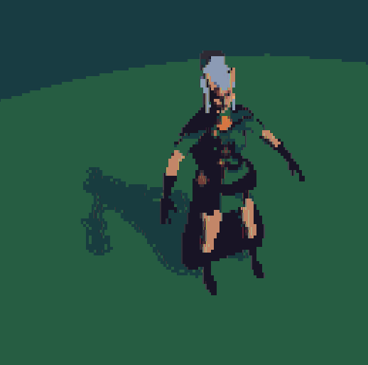

I did try to use the lut you showed before in my scene, looks like this, I also have some "lines" showing up :

If I set the texture filter back to bilinear, it looks great

I think those are different. Try downresing the image and posterizing it
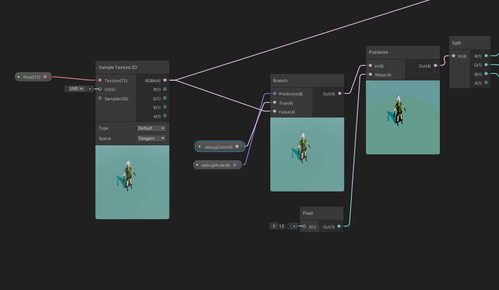

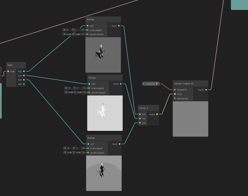
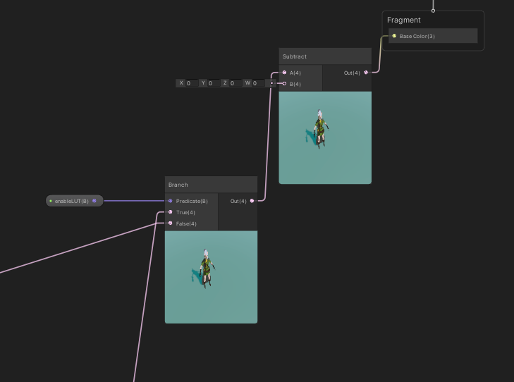

the input pixel is a render tex, posting that in a second
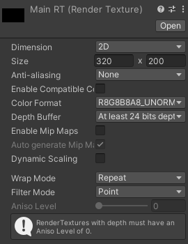

that's being driven by a camera naturally
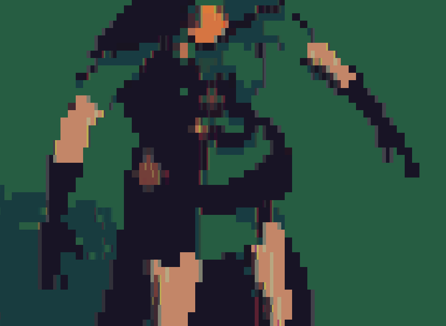
it's almost like there are 2 images on top of each other at slightly different positions
Could you post a screenshot of the RT before the filter, so I can use it in my test as input ?
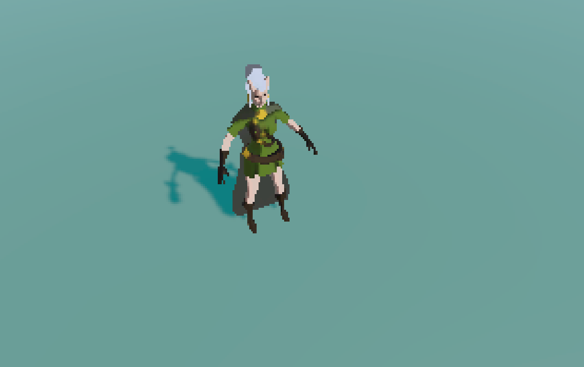
yep
kk
Oh, I got it, silly me
Disable mip map generation on your LUT texture
@coral geyser Just in case you missed it, URP has a built-in color lookup post process :

Oh what how does that work lol
Let me try that mip map thing haha
o wow
yeah that fixed it
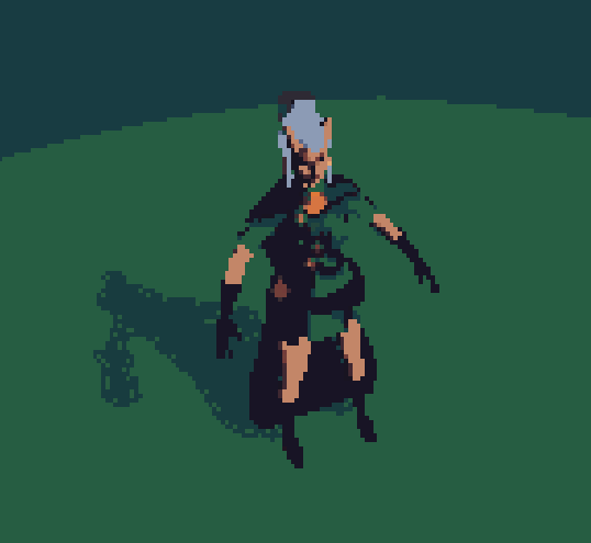

thanks!
https://i.gyazo.com/399d6dc8cdb8160b1f229e9eef5e41bc.png (with the sobel filter back on)
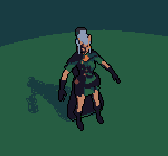

Also, you don't need to do the posterize in the shader if you already have your LUT posterized 😉
I KNOW I KNOW
If you're curious I made the lut generator public
needs node though
you install node and npm, then you run npm install . (This gets all the packages I used) then you run node generator.js
I'm to deep in nodal editors, I though you were saying that the tool needed some node workflow XD
oh no haha
this is nodejs
I'm sure you realized that
Also if you don't want to use the simple endesga-32 palette I provided, you'll need to create one, it's pretty simple, just any png will do, make sure every color in there is a color you want the LUT to have.
How can I choose a subshader with Render type tag value not RenderType?!
Also SetReplacement only works with camera and image effect shaders?
How can I switch between subshaders for an object in a script (runtime)?
ok I hate asking for help again so early but I'm so confused lol. I'm trying to make different layers, and it works in the preview but not in the actual viewport. Any idea what's going on?
https://i.gyazo.com/75b445d28d17494016432217171a311a.png the shader graph
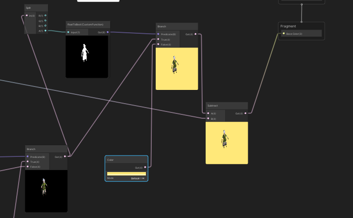

the output
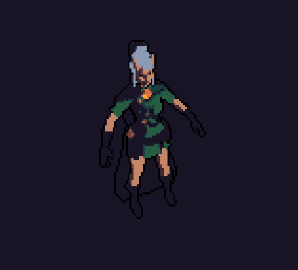

i dont have the pbr shader graph option, did i not import something?

technical artists, I need you lol
Where's that remy guy
I think the problem is that the camera is rendering stuff to the texture even when there isn't anything "visible to it" that hasn't been culled properly.
but it doesn't make sense why the previews would render properly but no the main window
https://i.gyazo.com/b91c978ef688823c4505cbcc7afe593c.png it's also doing this lol

Looks like you disabled the clear flags on the camera ?
looks cool tho
@amber saffron the opaque texture ones? There are a few cameras which capture each different layer. I've played around with the "opaque texture" things and haven't found a setting that works.
but I'd be open to anything you can think of
it do tho
first, let me have a breakfast
you're a boss dude
Can we actually create a texture via ShaderGraph? I have a Grid texture that I want to extract some squares depending on their black levels then separate them into "mini textures" of their own so I can scroll them indiviually
@amber saffron I have to sleep. I appreciate the help you've given me and if theres anything I can do to pay you back please let me know. Maybe I'll see if I can fix this layers issue after using the worlds best debugger (sleep lol)
You could either remap the coordinates with some (considerably easy; uvs are 0-1 in unity thankfully) math, or if you wanted an easier and more straightforward solution just split the grid up in photoshop and input the textures individually.. but since you're using a grid some math could look like float2 griduvs = floor(uvs * scale) and that'll get you a unique id for each section itself nicely named such as 0, 1, 2, etc., and you can go from there. just a thought
Hey folks, is there anyone around well versed in HLSL that could help me with an issue? I'm not sure how to go about doing what I want to do.
I have a fragment shader that has a Texture2D as a property. The shader does some sampling/interpolation of colours based on texture coordiantes. This works correctly, however I want to do some pre-processing on the Texture2D before I sample it.
Specficially, I want to "pad" the texture with a one pixel margin. This is only for the purposes of sampling and I do not want to change the underlying texture.
Now, I really don't know shaders at all so I don't know if the following is possible. If I were working in regular programming, I would just get the W/H of the texture, create a new texture of size W+2, H+2, then do a loop to fill each element with either my pad colour or the original colour based on the coordinate defined by the loop.
If anyone could give me some advice on this I'd really appreciate it
In shader code you would alter the UVs used to sample the texture to create this padding
You want to transform the [0;1] range of the texture to something that does [0-> 0 -> 1 -> 1]
This can easilly be done like this :
uv = saturate( uv * 0.8 + 0.1 );
Thanks for that, Got a few additional questions
By using that method, am I able to specify what the "pad colour" should be?
no
Ah, ok that's something I very much need to do unfortunately
Still possible, but you need to do more
You can use the UVs as a mask to display the texture and the "pad colour"
uv = saturate( uv * 0.8 + 0.1 );
float4 color = --- your texture sample code here --- ;
float2 uvsForMask = step(0.5, abs(uv - 0.5) );
float mask = min(uvsForMask .x, uvsForMask .y);
color = lerp( color, --- your padding color ---, mask);
Thanks very much Remy, I appreciate it,I'll give that a go and see where I get
Unfortunately I don't think this is going to work for me. The idea of interpolating between my texture sampled colour and my padding colour is sound, but I don't think this implementaiton works in my case, as modifying the UVs is going to impact the initial textrure sample.
Ideally what I'd like to do is:
- Sample Texture using normal UVs
- If UV coordinate is at the edge of the texture, interpolate to pad colour.
To put it in context, this is for trying to get rid of pixel-jitter on sprites at non-pixel-perfect locations. Essentally I want to say:
- "When the edge of the sprite does not fall perfectly onto the pixel grid, interpolate between the colour of the sprite's edge and transparent with a t-value based on how much of the screen pixel is occupied by the sprite"*
I found a shader that accomplishes this in the above manner for all the pixels *inside *the sprite, but isn't able to do so for the edges, as it is interpolating between colours on the Texture2D, and obviously "Edge Cooridnate +/1" does not exist on the texture, so in those cases I get no interpolation.
The thing that is really messing me up is that I'm really unsure of how to do this without branching or "if" statements
For future reference, I have found a way to detect the edges using some functions to avoid conditionals. My interpolation value is currently wrong but that's a simpler problem to solve.
Info here:
Computer Science, Machine Learning, Programming, Art, Mathematics, Philosophy, and Short Fiction
any idea why my refraction glass shader flickers between black and white color when built for webGL?

Not clear to me, but because I see that some of the pilars are flashing in the background depending on the view angle, I suspect some issue with the rendering order
yeah if I set the rendering order very low it just stays dark
problem is, once built for web the behaviour doesnt line up with in editor anymore so I have a hard time testing and debugging this
It seems some objects in the background are flickering too. Does this happen with opaque materials as well ?
I dont think so
maybe try change the queue of the glass,seems it is a render queue problem
Ive tested 7 different rq settings at this point
200, 1000, 1500, 2000, 2001, 2500, 3000, 3001, 4000, 5000
thats more than 7
but I tested all those
it eithers stays dark entirely or flickers in web
while in editor it stays dark at lower values and bright at higher ones
are the flickers object share the same material as the glass?
I'm looking at this fluffy tree tutorial https://youtu.be/iASMFba7GeI and I want to make something like it, but in VR. Therefore I can not use the view matrix to scale up each face, since this is too noticeable. Instead I would like to scale up each face based on its own vertex normal.
So as far as I can tell, I need to somehow be able to transform UV space to object space. Anyone got an idea how to achieve that?

It's called triplanar projection
You will probably need to edit the files uvs. Its doable tho
I would not do that in shader if I were you but it might be possible
Ok I'm awake and still quite confused. @amber saffron any idea what might be doing that? I'm also using a custom function to convert alpha to boolean, and the result looks as expected. The function is just out = (in>0.1)
Now I don't really get why you have a different result in the preview VS the rendering.
Like I said, it looks like a camera clear flag issue
How would i fix?
Well, what is the current settings for the camera clear flag ?
1 secundo
https://i.gyazo.com/b5b0ebebbeaeb96617c8e7bcf0c6ef4f.png camera 1 (main camera, for capturing the foreground)
https://i.gyazo.com/d5237479de9ac0e25eefb7ac63f145a2.png second camera for capturing the background (no LUT as you see)

depth camera for sobel filter
I'm doing what every game dev knows is the best way, which is to do the graphics first and make sure it looks perfect before doing anything gameplay related lol
Why does the first camera have background type set to "unitialized" ?
that's what the instructions said to do lol but I've turned it to a few different things and gotten similar results
(the instructions for the toon shader I originally used)
I suspect that this is the setting that causes the issue
it does, but it also renders the layer system inactive it seems
🤔 I don't get how you full setup is done here
It was extracting the alpha channel from the "main" camera (the first one) and if the alpha there was 0, it was rendering the other camera's data
And to do this, each camera renders in a RT, and both a composed in a shadergraph then output to the screen ?
(that was the intention at least)
yup
My instincts tell me you're about to tell me the better way lol
thing is I don't want the shader graph applying the palettization stuff we did yesterday to certain parts of the image
so my instincts say to create a layer/compositing system within shader graph
Generally speaking, I would avoid using multiple cameras
yeah and I can see why haha
I think the most efficient way would be to look at render features in URP
you can use it to render some objects to the stencil buffer, and than use it as a mask for you post process
I like the sound of that
Ok I have a renderer feature and it's masking the correct layer. The tutorials I find aren't for specifically what I'm doing. If you would be willing to point me in the right direction, that would be extremely helpeful
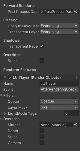

Potentially I could just use some kind of multiply or add feature but those always distort the colors
ughhh so frustrating, the system works in the preview lol
oh god I figured it out
I'm so goddamned dumb
Hey howdy! I need a little help with a shader I'm working on
In summary, I've got this portal shader:

It's got some vertex displacement and some animation
I want to make it so that it looks like it has depth behind it
Sort of like if there was a small room behind the portal, entirely coated in the same shader
I've achieved similar effects in HDRP by simply increasing the height of a heightmap but I don't know how this could be done in URP. Any help would be appreciated! :)
What's funny is that what I've been doing just now is actually fairly similar to this, zucc
Are you using shader graph?
it's a bit complicated. Long story short, I would recommend you create an actual room behind the portal with that effect applied as a material. Then you add that room to a layer and make that layer invisible to the main camera. Then you, in the shader graph, add the layer back in with a conditional. That's what I ended up doing.
Oh man, that's a shame cuz I can't have a room behind it :/ But thank you a lot for reaching out
oh why not?
I want the space behind the portal to be normaly walked in, like
portals aren't mounted to walls or anything. i want them to be able to stand simply in the middle of a room and be enterable in both directions
the room doesn't need to be visible or interactable in any way
and it only renders on the same pixels as the portal
How did you do that?
Well, I have a camera that can only see one layer handling the "Main" effects, then I have an identical camera as a child of the first which can only see the "Room" layer
then I have the "Portal" be a special color (like a pink or something that isn't used in the rest of the game), and the shader graph looks for that color
when it sees the color, it knows to draw the "room layer camera", then draw the portal fx
I see, I'll look into other solutions but if they won't work I'll do this. Thanks!
i used a cel shader tutorial with an outline but whenever i start my game everything is black, and its cause the outline is filling the inside of my player, and the camera is inside the player. i dont know how to fix it, can anyone help? https://pastebin.com/y4EYSZkv
Pastebin
Pastebin.com is the number one paste tool since 2002. Pastebin is a website where you can store text online for a set period of time.
I have made a UV map for my model in Blender, but it's not working (I am using URP and using a shader graph so I dont know how to add the UV) ... or am I supposed to unwrap the UV map in unity, and how do I do that if you dont mind telling me .. thank you
Is the UV map being exported? Are you using a material?
A stencil MIGHT work as well, depending on things like what you want to do about lighting. Then you don't have to "match colors up" (you're using that special color as a stencil mask).
That would be ideal haha but I've no idea how to do that
Well, if the "color" is just a mask in your portal object, maybe that's the best way (I re-read your post). Meh, it's all good.
Stencil is more about across-objects, and I'm also unsure on how it survives across cameras, as it is similar to the depth buffer, but it is a stencil buffer associated with the render texture for the camera.
Its not a portal for me, it's the background of the scene 😅
That sounds ideal but how do I do it lol
sorry I didn't see your reply.. the UV map has been made after the model was imported into unity\
is there a way I can apply it to the model?
The uv map was made AFTER it was imported? How was it made?
I used blender again ... just made a uv map because the default one gave me some problems when it comes to applying material
but if I add the new file.. I would have to redo all the animations (i have 42 and 2 animation cotrollers) it iwll take a long time which is why i am asking is there such a way
Ah yes. I think that would be an issue for the animations crowd. You'll likely be simply using the avatar system but I couldn't be sure as this is an issue I've had a lot myself
Try #🏃┃animation
There isnt any way to import just UVs as far as I know
they'll tell me about a way to copy the new animations instead of the old ones?
Your best bet would be simply remapping the old animations. Which would be the best way. Maybe someone else will have a way to remap UVs though, but I doubt it.
if there is a way, do you know where i should ask?
(btw i am using urp shaders... i was hoping there is a uv node that would help)
I guess here lol.
Maybe there's a way to do it in code?
assuming you still have the same number of UVs surely it's possible to manually read and reposition based on the read coordinates
Like I said, I'm not sure about stencils across cameras. Somehow you need to access the stencil from ?either? camera?
But just like a render texture/rendering can have a depth buffer, it also has a stencil buffer. You set up some drawing options (like a bit mask, and values to set/compare to) and when you draw, it sets the stencil for the object drawn that's the kicker. IDK if that works in your use case.
But if you have, say, a background you want to draw, you could have ALL your objects set the stencil where they are drawn (so you're setting it per pixel as always) and then wherever it isn't set will be background for some other pass. But all drawing/shaders would have to honor that stencil method.
Might just be easier in that example to check the depth buffer value.
@coral geyser thank you I appreciate it
Learn how to set up a Unity project with the Universal Render Pipeline (URP) and then add stencil buffers to create a see through objects effect.
heh I was looking at this exact post earlier
Unfortunately I was left still not knowing how to get the contents of the buffer in any meaningful way lol
Does [loop] not work in compute shaders?
Well, you have to kind of let the hardware do the filtering. That's a big performance win though. But you don't read it yourself in the shader code, you just set up the "filtering" and let the hardware do its magic.
Why would you need it in a compute shader?
You can do loops, of course.
damnit carpe magic should stay in the game!
lol
Like variable length loops
yes but what do you need it for
I'm throwing brush mesh generation of tiltbrush into the GPU
oh jesus
And I almost got it
But it looks like I can't use for loops unless I use unroll
But then why does [loop] not work?
[loop] doesn't sound like valid code afaik
but I don't really know shader language too well
It's defined in hlsl in microsoft documentation, maybe unity doesn't support it?? Or maybe I need to use some pragma stuff?
huh. I would think you could do variable length loops. Let me dig around.
The problem is that anything in a work-group shares the same program-counter. But I'd be surprised they can't be masked off.
Another way to do that, is to do the for-loop per shader-core with a max value, and use an IF to select what a particular core does.
So in pseudo-code:
and do a atomic max or some damn thing for all cores (group shared memory?)
for (loop = 0; loop < max-loop-count; loop++) {
if (loop index applies to this core) {
  Do this;
}
else {
  do this or nothing
}
}
Yeah, you would think it's doable. I didn't know that they share the same program counter, that might be part of it.
What I'm thinking I'll try is having some known maximum count, and breaking when the known passed in iteration is met.
Problem is, it seems like Unity's gonna unroll it no matter what, so that's going to be a big shader that takes forever to compile 😦
Depending on how you construct the loop, the [loop] might work. The compiler will allow it if it can get that max value for all cores to be the same value since they share the same PC. I think. Wink wink and 2 cents and double guess. 😉
I'll figure it out. I want my VR game to use tiltbrush art and I won't stop till I got it lol
I think you'll get it. Just try to make sure that the loop max value is some same-value-for-all-cores. Maybe even a max constant (oy, what a waste!).
if the compiler sees that it's not changing per core, [loop] SHOULD work. But if it changes per core, it cannot work (shared PC).
Holy shit I did it @meager pelican @coral geyser

I am getting this glitch from hdrp and cannot find what file it's coming from, anyone know the file type of a compute shader and how to fix this: Metal: Compute shader has 1024 threads in a thread group which is more than the supported max of 512 in this device
can I create geometry in a compute shader
@mystic dagger Yep but unless you know your shader stuff well it's a goddamn nightmare
that looks really good too dude wow

Hello bro, i want to make color streaks like the photo and be able to change its level. Please help me
Use [numthreads 8,8,1] in the shader, and dispatch the proper number of invocations in C#. Each thread might have to check if it needs to do anything, or should be "inactive" (using an IF).
do anyone have this kind of high res picture,everything is paid online

Hey!
I'm having trouble with porting my mobile game to iOS: It keeps saying that all of my shaders are not supported.
I read that now all iOS devices use the Metal API, does this mean that I need to rewrite my shaders completely for iOS? Or is there a setting somewhere that makes them compatible?
I have a problem
i use disolve effect
but I want it to only go one way (for my object to disappear) not for it to appear

I doubt I can get an answer here as its about a raymarching renderer I made with HLSL but
Does anyone know why when I hate a lot of spheres or any object like this it causes this effect?

I dont really seek to fix it as its not a huge deal but Im just wondering what causes this effect on far away objects
@distant sleet This is called a "moiré effect"
When seen from far away, a single pixel will only be able to display the surface of one of your sphere, when theorically there could be two or more there. Add some float precision issue to this and you get this effect.
It's similar to trying to display a texture with visible tiling from far away without filtering.
To fix the issue, on texture we use mip maps, and in you case you would need some sort of aliasing or sub-pixel sampling
Ahh very interesting, I'll search it up
thanks a ton I didnt know how to google it lol
I thought that it would be a floating point precision error yeah
Thanks
Hello, I have no idea how to shader program and i copy and pasted this shader. It gives me an implicit vector truncation warning in unity which kinda annoys me for that last line, how can I remove it?

I dont know the types of these variables but
That warning means you are trying to mutliply 2 vectors with differing lengths such as a float3 and float4
Just change it from (float4) to (float4).xyz
And that will explicitly truncate it
^^
I have a problem, I'm trying to use the _Time variable in a compute shader

My IDE says it isnt declared which makes sense as it only has general HLSL error detecting, but my compute shader doesn't work anymore.
I did float test = _Time.x
Hiya guys, just an idea i will be working on in weeks to come, planning to use this in my projects and also making it free stuff on asset store once it gets enough tight and tested. Idea is simple and is having gpu assisted (any math accelerated) without using compute shaders. Basically there will be C# library(middle man) that you can use while coding and that library will talk to the shader exposed fields(and exposed properties) will serve as inputs and outputs. To my mind this is dumb simple and yet it should save a lot of cpu power. What you guys think about this, does anyone sees some obvious problems with it or? Asking for experts opinion since i am not much into shaders that much(just making eye candies here and there hehe). I think there would not be racing problems since while you are coding you are deciding when and how to use the computed output from the shader/library.
Ok, StructuredBuffers are kind of confusing now as I'm just learning about them.. but microsofts documentation isnt really helpful
Anyone have good info on how they work
Does the vertex shader interpolate EVERY variable for the fragment shader? If so, is it common to store information other than lightcolor/uv/pos within the vertex struct?
I think I understand them now, so they directly copy byte data in the same structure as the elements they hold? As in
If they contain structs that go float f1, float f2, float3 vector
Then they have 4 bytes for f1, followed by 4 bytes if f2 and then 12 bytes for vector
Meaning if a computebuffer that goes 3f800000 3fc00000 3f800000 41200000 3f800000
Which is as floats, 1 1.5 1 2 1
Then f1 would be 1, f2 1.5, and vector (1, 2, 1)
Correct me if I'm wrong if thats not how they copy data from a computebuffer to the structuredbuffer
hello. i have one question. i have vertices and indices in Graphicsbuffers and i want generate the mesh using GPU. but im little confused. Drawproceduralnow using both buffers to generate? or i need to write code in shader? i think i have both needing datas to generate mesh. Do i need to dispatch?
By default, yes, unless you use the [flat] attribute in OpenGL 4.0 or "nointerpolation" in HLSL. Surface shaders excepted. But if, say, all three verts put the same value into a float3 foo, what's there to interpret? (although it will tie up an interpolator unless you use flat).
See section 4.5 here for OpenGL.
https://www.khronos.org/registry/OpenGL/specs/gl/GLSLangSpec.4.50.pdf#page=86
and for HLSL:
https://docs.microsoft.com/en-us/windows/win32/direct3dhlsl/dx-graphics-hlsl-struct
Note version requirements.
Struct Type
Thank you!
Another question that has been bothering me: is there an inherit difference between "per-pixel lights" and "per-vertex lights"? Or are the types entirely based on how you implement them? I keep hearing how people use them in different situations, but I don't understand what is done to properly define what light to use. From my understanding, it depends on if you calculate lighting in the vertex/fragment shader. Is that correct?
Yes, basically. If calculated in the vertex stage, it interpolates the light value across the polygon based on vert interpolation. Whereas with per-pixel lights, it is calculated as you'd assume...for each and every pixel location.
Obviously, per vertex is a lot faster, but less accurate. And in some methods, IIRC, lights are always pixel lights for proper shading.