#archived-shaders
1 messages · Page 212 of 1
Now I get it, thanks @mental bone @regal stag
Shader Graph ... it looks pretty, but I don't get it and the tutorials are all youtube videos that make me want to scream after 5 seconds. Is there a decent web page plain text no sound tutorial for it?
TMP (TextMeshPro) uses TMP_BaseShaderGUI.cs and TMP_SDFShaderGUI.cs to draw the material editor. Changes to these are not retained during restarts of Unity. How can custom versions of these editor Inspector drawers be made?
It's not ready to use. Avoid it if you can.
OK, fair enough
trying to figure it out has led me down a rabbit hole of URPs and HDRPs and all sorts - I haven't used unity for a few years I feel like I've missed a few things
Ignore their claims of URP/HDRP and SRPs being production ready. They're miles from it. Use Unity as you would have used it 5+ years ago to have a good experience. Even download 2017.LTS to hold yourself in that frame of reference and context until you need something in the newer versions. You'll get far further this way.
That's the impression the forums are giving me too
I have a post here https://www.cyanilux.com/tutorials/intro-to-shader-graph/ along with other text based tutorials on that site if interested. Can also check out https://danielilett.com/ and https://minionsart.github.io/tutorials/ has some SG tutorials too.
thankyou Cyan. I think I'm going to back off from it until it's a bit more mature and make shaders the old way though
Until they gain the good sense to think about visual editors in a holistic sense, in conjunction with coded shaders and vfx and animation and UI all being part of a properly considered creative experience, ignore everything new they roll out... including everything since 2018. It's been an absolute debacle.
Yah, I prefer editing text. I also prefer editing my code in a way that my source code control system understands.
the good news: Moore's law. it's meant that much of the old Builtin is performant on modern devices. And there's a huge array of knowledge from the old ways of using shaders and lighting that's still pertinent and accurate because they put Builtin Renderer on ice once they started with the SRPs
I hate writing code. But the Unity efforts at visual representations are so bad I'd rather code.
my experience so far with visual editing has always been that I'd rather code
even when designed specifically for small children the small children come back and say "we'd rather just use python"
I'm sure my question is stupid but is it possible to "export" a blender eevee shader made with its shader graph, to unity ?
Or can i just reproduce the shader from Eevee into unity ?

You'd need to rewrite it, with Unity's Shader Graph (or other node based tools like Amplify Shader Editor), or via shader code (cg/hlsl)
Ok, i see. I'll try to reproduce it into unity shader graph then. Is it easier with amplify ?
And is it hard to do for someone that never made any shaders but know programming ?
They're similar. I haven't used Amplify but I think it exposes a bit more things than Shader Graph and it can be used with the built-in RP. Shader Graph can only be used with built-in with 2021.2 I think (which is a beta version, not properly released yet), otherwise you'd need to be using URP or HDRP.
it seems like I've somehow made my ray tracing function bidirectional xD
Any ideas how I messed up?

here's the functions I use for the ray generation and checking:
Ray GetCameraRay(uint2 screenpos){
    //convert pixel coordinates to a [-1, 1] range
    float2 uv = PixelToUv(screenpos);

    float3 origin = mul(_CamToWorld, float4(0,0,0,1)).xyz;
    float3 direction = mul(_CamInverseProjection, float4(uv,0,1)).xyz;
    direction = mul(_CamToWorld, float4(direction, 0.0f)).xyz;
    direction = normalize(direction);

    Ray r;
    r.origin = origin;
    r.direction = direction;
    return r;
}


//Check if Ray `r` intersects with AABB `box`
RayHit CheckIntersect(Ray r, uint box){
    Box b = UnpackBox(box);
    float3 imin = (b.min - r.origin)/r.direction;
    float3 imax = (b.max - r.origin)/r.direction;

    float3 tmin = min(imin, imax);
    float3 tmax = max(imin, imax);

    float cmin = max(max(tmin.x, tmin.y), tmin.z);
    float cmax = min(min(tmax.x, tmax.y), tmax.z);

    RayHit result;
    result.hit = (cmin <= cmax);
    result.distance = cmin;

    return result;
}
There have been very few (less than a handful) good visual abstractions of coded sequences. Part of the problem has been the engagements of two types of fools. Traditional coders trying to represent what they do visually, and non coders trying to imagine what coding might look like visually.
Unity's ShaderGraph didn't even start with any effort to abstract, let alone understand the entire (quite small) market of visual material editors and shader editors of the recent past. And it is, so far as I can tell, completely unnecessary.
The fact that most users of 3ds Max prefer the classical material editor over what is otherwise a quite good flow mechanism for creating materials should have indicated that there's more inherent paradigms pre-existing within Unity suitable to making a first step towards more accessible shader creativity and editing.
personally I think the visual graph style does translate better to folks that can'
can't code
especially with the realtime previews
over time with more builtin nodes/more available tutorial resources I think shadergraph will be a win for people that otherwise would have low ability to approach something like writing a shader
Professionally I work on a product that does a similar thing for data processing, and we use a node/graph based language to expose the ability to manipulate data to less technical folks and it works well.
This is the low standards problem, referenced by the commentary on the two types of folks making graphs for this supposed audience. For them, it's presumed that anything is better than code, so any visualisation is "good enough". This is a folly.
Well it's true
There's a large segment of people that don't want to look at code
With the custom function nodes it's really not hard to just write code
Maybe long term they need to make it even easier for power users
You'd need to use stencils to do something like that. e.g. Have the alpha clipped mesh material/pass write a value to the stencil buffer (Ref 1, Comp Always, Pass Replace). Then render the other material/pass with same reference & Equal comparison.
How to make wet Shader for terrain using URP. There is no tutorial.
I often see questions phrased like this. Perhaps you shouldn't be looking for a "how to do this very specific thing so I can copy and modify"-tutorial, but zoom out a little and try to acquire some more general knowledge.
Think about which characteristics that makes a material seem wet, and see if you can learn some techniques that you can use to achieve that in your shader
I've been trying to limit my ray tracing shader to a specific area of the screen, but I'm getting some weird results.
With a Rect rect that i want to check within, I dispatch with thread groups of rect.width/threadCount and rect.Height/threadCount
Then I set a shader variable "pixelOffset" to rect.min and get the pixel coordinate with
uint2 pixel = id.xy + pixelOffset;
did i miss anything?
I have a strange bug where some shaders defining SV_Depth on metal refuse to compile. Has anyone else encountered that?
there's no mention of it being unsupported on Metal in the manual
only thing I can think of is that the broken shader is "RenderType" = "TransparentCutout" and the working shader is "RenderType" = "Opaque" - it makes sense that transparent cutout can't define SV_Depth, but its infuriating it only throws the error on Metal if so
anyone have any experience using "UNITY_SAMPLE_TEX2DARRAY_GRAD" I can't seem to use it.. I'm always getting undeclared identifier errors
is it possible to make an image effect shader use the post-shader versions of each object instead of their original meshes
nvm
so right now i have this cel shader, and it's fine, but how would i go about seperating the shadow into 2 or more bands, if possible?

i'm currently using a smoothstep node to seperate it into two

ping me if you got smtn
@safe gate posterize node
thx
Anyone know how to fill the cutaway area from an alpha clip in Shader Graph? Something like this

@strong merlin for something like this, I did this before by not using alpha clip but moving down the top vertices in the vertex shader, and coloring them based on whether they were moved or not
Ah, that's a good idea. In my case I want to maintain the colour anyway, so one less thing to think about. I imagine that's done by passing the clip plane normal position (so just the y value for me) into into the vertex position?
IDK for sure, but I doubt it's as simple as "+ pixel offset"....depending on how you calculate that.
I'd bust it up into full screen x and y values, then do the calc, figuring out the pixel as real-y*texture-width + real-x. So your rect xy is just there as your "loop" counter. IDK if that makes much sense, it's early for me. lol.
So it's probably real-y = rec-y + y-offset, and real-x = rec-x + x-offset, and THEN multiply out using the width * real-y + real-x.
Test it by coloring your rect red or something and checking the result (maybe in frame debugger if you output to something like a render texture/target).
@devout quarry worked perfectly

Thanks a lot for your input!
Turns out I'm actually just retarded. I use the total screen size to remap the pixel coordinates to a [-1, 1] space, and I had somehow set both dimensions equal to "screenWidth", causing calculations everywhere else to be messed up.
But hey, on the bright side it only took me like 1-2 hours to realize!
Is there a way to modify the shader stage order? With the same thing I was doing above, I am modifying the position, but I need to modify the alpha based on the original position
I have a kinda silly idea. What would be the best approach(in URP) to do a geometry shader I can put on everything(similar to 'curved world') shaders that would work with a ortho camera and allow scaling of geometry based on how far from the camera a vertex is?
Just scaling towards the center of the screen, or...?
You save the original position and pass that in the interpolators to the frag, before you modify it.
Or possibly calc the alpha in the vert stage if it is the same for the polygon.
If you're in shader graph, see the recent section on custom interpolators
Using shader graph yeah. I'll have a look up of that
Hi all. Is there a way to use variable frame duration with flipbook node in shader graph? In my project i have sprite animation i've implemented through flipbook node, but i want to specify each frame duration.
my shader looks different when i export to WebGL. part of it glows when it's in editor but the glow gets removed. is that a normal thing?
WebGL doesn't support quite a few things
In compute shaders, can [numthreads(x,y,z)] be set dynamically or is that a meta/compile time kinda thing?
Would you need to use indirect dispatching to do that?
that's good to know, thank you. i'll see if the glow shows up on desktop export
Don't use _Time, but pass the time in yourself. Or the offset. Whatever.
AFAIK, it's hard-coded.
So to the 2nd question, no. DispatchIndirect is more about what kernel gets called with what data.
I want to make a 3-way lerp function so I made this:

The problem is that it doesn't work with 0.5 and 1 because of the fmod() portion
Adding a "+ floor(value)" to the fmod() solves the 1 but not the 0.5

Let me try to write it out
Yeah sorry for the nodes but it's a solution from remy that worked for me, it should translate easily to code
Had another problem with my vertex-clipping shader @devout quarry. I'm using the position (object) node in a bunch of the criteria, and in the preview window it looks fine, but when put into the scene parts of the shader calculate the wrong position by a factor of x2. Any idea what the cause might be?
@strong merlin not on PC right now so can't check my code but I feel like position in object space should work? Move it in the y direction by its height relative to the center of the object
This was my result, this is the kind of thing you're trying to achieve right?
Working on some new mesh-slicing tech 🍊🔪 #madewithunity #vfx #gamedev https://t.co/2kR6AuXbRA https://t.co/15pYhxPVX9
Likes
197

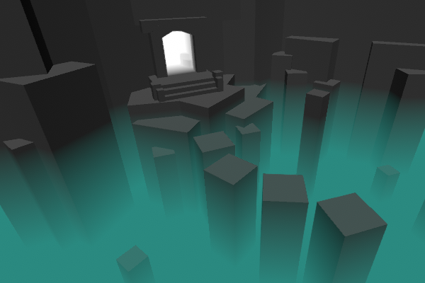
Anyone have a shader for vertical fog a la Monument Valley? I've tried a bunch I've found and none work

Yeah that's exactly what I was trying to do, except I only need it from the y axis. Not sure why mine isn't working then. I'll load up my graph tomorrow when I'm back on my PC, but it works perfectly in the preview
@rare charm if you use urp try this https://www.google.com/amp/s/cyangamedev.wordpress.com/2019/12/05/fog-plane-shader-breakdown/amp/
I’ve moved to a new site!An updated version of this post can be found here, with no ads : Intro This post includes two examples to produce fog shader effects. In both cases, the shader is app…
To add to this, if you're using orthographic projections like Monument Valley too you'll need to handle depth based stuff differently. This may give some hints to achieve that : https://www.cyanilux.com/tutorials/depth/#mesh-orthographic
I am using an ortho camera. I know almost nothing about shaders, but an asset I tried had an ortho option and didn't work at all either so 🤷♂️
Hi! I've a sprite renderer and a tilemap renderer with a custom shader, the tilemap renderer seems to be taking light completely fine but the sprite one doesnt seems to be inverted https://i.imgur.com/qp59FWL.gif
Do you guys know any fix for this?
Here's the shaders, shadergraph code

This produces exactly nothing when I copy the graph into my project.
you can just create a shader that blends color based on worldspace height (y). Faster and no need for depth buffer
hi, i have what i think is either a simple problem or an intractable problem, but I'm a layman with shaders: what i want to do is take two meshes/triangles in the same space with similar shapes, but then have a shader render one in front of the other. this is for drawing procedural roads on procedural terrain, but i'm thinking a similar process would be used if you wanted to put a graffiti tag on a wall (triangles in the same place but one's in front). I've read this might be possible and is simple shader code but I can't tell if i've misunderstood it
Wouldn't that require me to use that shader for every object in the scene?
I'm trying to make a shader to shift colors in a specific way (as opposed to just changing the image color, which doesn't do it quite right). However, I'm getting an artifact, even when it does nothing.
fixed4 frag (v2f i) : SV_Target
{
    fixed4 col = tex2D(_MainTex, i.uv);
    return col;
}
The first image is what I'm getting and the second is what it's supposed to be (i.e., the transparency is causing issues)


So in typical Unity fashion I changed nothing and now it works. Kind of. In my Scene view it looks great, in my Game view it doesn't blend at all...

Is it at all possible to make a cutout have alpha for fade-in/out?
I got RenderDoc up and running and was able to check the values for the pixels. They're as they should, but they don't match what I'm seeing. For example, the main area, which is rendered correctly, is 0.98039, 0.86275, 0.76471, 1.00. As for wrongly rendered stuff, the darkly colored stuff at the bottom of the first picture comes up as 0.2902, 0.23529, 0.19216, 0.00. 0 alpha, so it shouldn't be showing. At yet it shows up.
Updating the colors when the alpha is 0 should, as far as I understand, do nothing, but it very clearly does. For example, I can do this code and end up with this picture:
fixed4 frag (v2f i) : SV_Target
{
    fixed4 col = tex2D(_MainTex, i.uv);
    if (col.a == 0)
    {
        return fixed4(1, 0, 1, 0);
    }
    return col;
}

are you sure it's not bc the background of the image is black and it's showing bc the pixels on top have 0 alpha
The color replacement like I did in that latest picture wouldn't have worked if it was that. It's rendering as opaque.
Yeah, I guess so, but it's not a bad thing I guess. Assuming your player and other interactable objects stay above the fog, you only need to apply the shader on the static background/level.
@rare charm depth texture enabled?
Hi, I've created a custom billboarding shader that changes a sprite based on what direction you look at it using Shader Graph. I'm using a material property to add "animations" (basically just changing what part of the sprite sheet to show by feeding it a float). Is there a way to have this property be unique per instance of the material? When I change it on one thing everything else with the material changes too.
Tried to check the "hybrid per instance" box in shader graph but that seems to make setting the property in script not work (although I can read and set the property correctly, it isn't reflected in the shader)
Where/What is the file that generates the Builtin GUI in Editor Inspector for shaders like Particles? How does one find, access and edit this file?
If you change it in the Shader Graph, you're changing the Shader. If you create an Inspector Editor GUI for your shader, you can change instance properties.
Hi, i'm using the urp 2d renderer for lighting. How can I make a material that is a blend between lit and unlit? Any help would be appreciated!
@empty wyvernIf you're in the transparent queue, it should blend "nothing" with an alpha zero. But if you're in opaque you get that black background, since alpha zero is irrelevant.
You can use
clip(col.a - .001);
if you're in opaque to cull the output of the pixel if you wish.
You need to investigate Material Property Blocks.
IDK the status of them in SG though. Sadly. For the regular pipeline, they're per-instance. But for SG is used to be that only certain things worked for that, like BaseColor. IDK currently though, moving target.
Research "decals"....that shows the technique you've referenced. Then maybe you can apply it to the roads.
Thank you for the replies! Is the info here about ShaderGraph material property overrides not accurate then? https://docs.unity3d.com/Packages/com.unity.rendering.hybrid@0.4/manual/index.html

I'm using URP and DOTS
IDK, like I said, I'm not really 100% up to speed on the "moving target" particularly if you include DOTS. So...try it. 😉 If they say it should work it should.
Had some issues with implementation, wasn't as straightforward as I'd hoped (or maybe I'm just slow lol) but it seems to be working
Now I'm looking for a way to swap the texture used per material instance
Hey guys, using HDRP and CustomPass
how come when I input a specific value for my color(e.g. (float4(.75, 0, 0, 1))
it comes out as .88 when I examine it with a color picker
this is in a custom render texture
and linear color space
i guess it's getting converted to gamma space
If you pulled it off at all you're not "slow" 😉
Shaders are "hard" when you get into all the details.
Good show.
P.S.
Depending on your needs, you could look into a texture array, and just pass the requisite index for each instance.
haha appreciate it. actually looking into a texture array right now!
how do you render to a 3d texture in a vertex/GS/frag shader in HDRP ? Specifically accessing the slice you're rendering to
https://docs.microsoft.com/en-us/windows/win32/direct3dhlsl/dx-graphics-hlsl-tex3d
(the z value is the index into the array). As for stage, you may need an LOD version if you're not in the frag().
Samples a 3D texture.
https://docs.microsoft.com/en-us/windows/win32/direct3dhlsl/dx-graphics-hlsl-tex3dlod
in that case, z is the index, and w is the LOD level.
Samples a 3D texture with mipmaps. The mipmap LOD is specified in t.w.
hello everyone, i have an image effect shader but i only want it to be applied to one specific layer. i tried making a second camera for that layer but i couldn't get both cameras to display at once but still not display stuff that is covered by objects in the other layer. can i do that somehow? sorry if that made no sense whatsoever
hello, im following a brackys tutorial where we make 2d objects glow with emission maps, and im having some trouble adding them together, they just dont want to, the output is the same as the sprite sheet, and when i try to multiply is the other way around, i only get the emmion map
make sure u have post processing stack and necessary hardware(gpu)
but a gpu which does not support glow should not run unity so make sure u have postprocessing
*necessary effect search it up on google
Hi, I wrote a shader using ShaderGraph for multidirectional textures/sprites. The multidirectional part works, but the textures are drawing over each other in-game. Would anyone know how to fix this?
As in, I'll have two sprites side by side. They look great when viewing them from the front, but if I walk to the right of the rightmost one I can see the left one drawn over the right one.
This shader is the example "URP basic unlit shared" from https://docs.unity3d.com/Packages/com.unity.render-pipelines.universal@12.0/manual/writing-shaders-urp-basic-unlit-structure.html.
Can anyone explain why the grid is visible through the object? It's driving me crazy

Okay, so my lighting gets messed up in the build, but looks okay in the editor. could anyone help me understand why this happens? is there an option in the player settings that causes it?

Is there any way to reduce flickering of the normals in the depth-normal texture? I'm trying to do lighting calculations for a custom cel shaded light, but the flickering normals cause weird artifacts on the edges of the bands.

Hi everyone. So my confidence with writing shaders isnt high enough for me to write it all from code. But is there any way to include the UnityCG.cginc file in a custom node?
Or will I have to have a long list of inputs from other nodes to access information like time, location, uv, screen size etc?
Also is it possible to compile and apply shaders at runtime?
I think this is a pretty common issue but I can't find anything on google somehow. Does anybody know why this flips my y-axis and how do I solve it??
https://hastebin.com/isujobiser.properties (edited link)
not sure if i should be using screenPos instead and how to get it to work

altering a texture on screen to be transparent or opaque and adhere to a grid
think this fixed it thanks ducky
fixed4 tempCol = tex2D(_OnScreenTileStatus, (i.pos.xy + float2(camOffset.x, -camOffset.y)) / float2(_ScreenParams.x, -_ScreenParams.y ));
you should also check this, and check onboth dx and ogl platforms separately: https://docs.unity3d.com/530/Documentation/Manual/SL-PlatformDifferences.html
The Unity Manual helps you learn and use the Unity engine. With the Unity engine you can create 2D and 3D games, apps and experiences.
thank you
Anyone knows what might cause this blue area? It moves as I move in editor.. weird

It like cuts the water

if u could provide shader file maybe i could get a grasp of it
but u might render the water layer from other camera and paste it on top of it but wave details may end up small
so i suggest u solve it from its root(shader)
I don't think it's because of the shader because when I create a new scene and do the same thing there was no problem
Not sure what happened in that scene though
Btw here's the shader I tried https://github.com/danielshervheim/unity-stylized-water
Mhm couldnt think of what might be the problem
maybe it has got to do with camera change near clipping plane and see if that persists but nah dont think so
Already tried that, didn't do anything.
Anyway it works fine on a new scene
When i get to computer maybe i could take a look
Oh k then
Thanks though
hey guys
i want to render to a 3d texture
which i see requires a geometry shader to emit vertices for each slice
how do i instance render a full screen quad using CoreUtil / HDUtil?
I'm using a Custom Pass in HDRP
all I see is CoreUtil.DrawFullScreen
maybe ill just do 32 draw calls, 1 for each slice
fk it yolo
Hi, I'm having the following issue with my custom ShaderGraph shader. The textures seem to be drawing over each other (these are imported as textures and not sprites, not sure if that would cause any issues with render queue). Would anyone know how to fix?


i'll check right now
idk
probably have to look at the compiled shader code
i dont use shadergraph as much so can't help
ah ok, yeah i just googled and as of last friday its not available in URP haha
thread was here: https://forum.unity.com/threads/zwrite-in-shader-graph.719012/

Unity Forum
Can we set ZTest and ZWrite in shader graph?
I am creating an unlit shader graph in lwrp. The aim of this shader is stylized flat shading with...
maybe i can just edit the shader file directly
should be able to
Editing led to this effect

Is this an issue with the transparency?
It's weird because I can kinda see stuff through it
transparency was my second guess
I suppose its like a queuing problem, where some stuff is getting sorted behind and some in front
actually
i can probably use a compute shader for this
and just use the thread id to specify the slice
hi, I have a problem with the way I'm projecting my 2d objects into 3d space. In this scene a psb is being recorded by a camera and projected onto a plane using a render texture, but the texture is smearing. There used to be a setting on the right side of the screen that fixed it, but I think in updating unity it might have been removed. Do you know of any other way to fix it? -Thanks

Set your shader to Opaque and use Alpha Clip
(What does PSB mean?)
Can you set the sampler mode on the render texture to point?
It’s a type of 2d file, I found the problem a little earlier today by changing the background color from uninitialized to a solid color and making that color transparent
by smearing, do you mean blurring of the texture?
This fixed it 😮 tyty
does anyone know how i would add to my 2d sprites? i watched brackys video on it, but it seems to be outdated
No, it wasn’t an issue of blurring, but rather frames not disappearing after being displayed. I have it all fixed at this point, but every action taken before was shown so you ended up with a jumbled mess. In that shot that I sent the strange object on the right side was actually three squares that had smeared across after I moved the camera
Hello, does anyone know how to blend make a blend between a lit and unlit material? The effect I am trying to achieve is equivalent to overlaying a transparent unlit sprite on top of a lit sprite. I'm using the URP 2d renderer 🙂
Hey all, long time listener, first time caller. Does anyone know if the custom data in a particle system is available for the trails material or how to get that data in the trails module?
is there shader code to tell a mesh to be rendered as if it were at a different position when calculating depth? So, two meshes occupying the same space, but one is rendered as if it were at y+1, so it's rendered first when viewed from above?
like zwrite is on, but it's actually not where the vertices say they are
okay i've found 'offset' to add in a pass, which looks like what i want, but adjusting those values a) makes my polygons render bright white, b) doesn't solve z-fighting, and c) loses all the bells and whistles in the standard shader
I'm starting with the most basic shader you can imagine, literally just outputing a single color in the frag shader. On screen (URP), it renders as transparent (can see grid through it). How do I make this opaque? What is the equiv shaderlab/HLSL to setting SurfaceType = Opaque as in the builting URP/Unlit shader?
Put the unlit on the emission channel and the lit on the albedo - then lerp each to black as f (for the emission), 1-f (for the albedo) - when f is 1 the unlit material is used, when f is zero the lit material is used
You can use the SV_Depth semantic to output custom depth values. There is a performance cost because it must not compete the fragments before depth sorting them, but imo it's not prohibitive
Sounds like the scene gizmo is being drawn over your shader. Does your shader write to scene depth?
that's interesting, i'm looking up documentation on that, thanks very much!
Working on a minigame for a project. On the left is the example given by artists, on the right is the pieces of art put together. I am not able to use the Unity UI library. I need to achieve an effect whereby a portion of the red circle is rendered. The player has to click the JUMP button at the right time. I'm quite new to Unity Shaders. Any help is much appreciated. @me if you have some ideas :)

boy are you in luck today: https://bgolus.medium.com/progressing-in-circles-13452434fdb9

I shoulda kept reading that... I saw the UI thing and clicked off of it 
It's a very comprehensive and detailed article 🙂
you probably want to use that as a base, and then also sample a texture (that looks like an empty stopwatch) and combine the two to produce your final stopwatch+progress bar
it will be substantially easier if you don't have hands on the stop watch
That's a separate game object that I'm going to spin around
Shouldn't I be able to modify the values in the shader here? I've not worked with shaders in unity in quite a few years.


Nvm, stupidly forgot I had ctrl+R to refresh the Imported shader
is there a way to have different normal maps for each color channel in shader graph?
sure you just have to wire it all up in the graph
how would you apply the normal map to the individual channels though? i don't see anything in the documentation that would help with that, afaik the only way to put normal maps into effect in the shader graph is to wire it into the normal output
Is it just me or is the Rotate About Axis node in Shader Graph missing a pivot point input? I cannot get it to work in relation to actual vertex/object positions. my vertices always rotate around 0,0,0 in world space?

I believe so. I have ZWrite on and I've tagged it for the geometry queue. It took me a while to realize, but the shader renders normally, it's only in the scene view that it shows up weird. It's super annoying to navigate the scene, but at least it is rendering as expected ... the built in URP/Unlit shader actually changes in scene view when you toggle opacity
can i see a picture?
I would have expected that if the vertex inputs are in object space it should be rotating around object space?
yeah I'll link you a thread I made on the forums (this is a small thing but it's really bothering me) instead of dumping pics here
https://forum.unity.com/threads/urp-unlit-shader-transparency-in-scene-view.1143764/
Unity Forum
This is really getting to me. I would like to know if this is a UI quirk or something is legitimately different about this shader:
The standard...
This is only a guess, but it may relate to how Unity produces a depth texture. I know some versions/platforms use shader substitution to produce the Depth or DepthNormals texture, perhaps that texture is used in drawing the scene gizmos? If so, maybe the substitution is only applied for Opaque objects?
interesting, that gives me things to look into at least. I guess maybe a more fundamental question then is how do you define the object as opaque in shaderlab/HLSL? I tried looking at the source for the built-in shader but couldn't find anything obvious. I couldn't line up the inspector fields with the fields in the shader itself, so I didn't know what transparent/opaque was actually toggling. But, it seemed like that would be a surefire way to figure out the answer
That’s what makes it so confusing. It’s as if it’s taking the axis of 0,0,1 and using that as a word space pivot or something
I expect it to work as in the screenshot, but I have no idea what’s making everything rotate around 0,0,0
hi, i'm playing around with shader graph in hdrp and i notice that whenever i plug something into the "base color" input on the fragment, the shaded object becomes blinding like it is reflecting the full intensity of the scene light. i've attempted to adjust my exposure to see if that helps, with no improvement. can someone explain what is happening so i can learn the root cause here?
Yeah, see the "inline sampler states" section here : https://docs.unity3d.com/Manual/SL-SamplerStates.html
@regal stag great! thanks 🙂
i have a question, is programming shaders better than using their nodes?
It's ultimately the same in the end, really. Do whatever is better for you.
how do i get the game window's screen size
Screen.width / Screen.height returns editor window size
_ScreenParams returns the camera's target texture width / height
which doesnt match up with the editor window size which is fking up my UVs lol
when using Varyings i.positionCS / _ScreenParams
I'm attempting to learn some shadergraph/urp and some simple things don't seem to make sense to me. I have a plane. I give it a material/shader. That shader is simply a Scene Color node into the Fragment Base Color. It renders as a medium opaque gray. Shouldn't it look transparent?

anybody know whats going on here?

I can't for the life of my figure out why it just wants to go to white
but this works

FIXED!!
I need to use float4()
why would it be automatically transparent? is the alpha < 1?
Hello
You need to enable the Opaque Texture on the URP Asset (and should make sure graph is using Transparent surface mode)
Is there a way to find out where the GPU is spending time?
I'd like to know if a shader is memory bound or compute bound, and if it's properly executing in parallel or if it's just spending a bunch of time waiting for other threads
I realise that I'm not going to get the full "profiler" experience with the GPU, but it'd be nice with a rough approximation, or anything that could suggest if the bottleneck is one or the other
actual GPU profiling pretty much just gives me "yeah, I waited for that dude forever"
not much to go on
There is a frame debugger and profiler is good too! Also you can try using renderdoc for a complete frame analysis 🧐
Yeah I tried taking a quick look at a captured frame from RenderDoc, and I was mainly able to find bits and pieces of information about different render resources, not a lot of stats about the actual process.
I guess I need to dive into the manual a bit. I was mostly just blindly clicking on buttons and menuItems, looking for any words I recognised (which weren't a lot)
I'm not even sure RD is the tool for the job. It seems most focus on... well, rendering.
Since it's a compute shader I'm investigating, it's not really a rendering step. not directly, anyway
No, actually it does display debug information for compute shaders... I guess I'll see if I can make any sense of it xD
Is it possible to draw something on a plane using raycast and shaders? I have used setpixed() but it is very slow
I'm making an indicator that shows where the player is modifying the terrain, this picture shows what it looks like. But as you can see, there's some z-fighting going on, and the ring may sometimes go under the terrain and be hidden. Is there a way I can ensure that the indicator is rendered above the terrain? I'm doing this with shader graph. One idea I had was to just render the indicator a bit higher, like 0.05 units but that feels a bit hacky.

I just tried rendering it a bit higher, and it didn't really work, it just moved the problem a bit higher
A force field shader could help, but it can't have a thickness. I also thought about a decal projector and that's what I'll probably use
Hey guys,
I have a street mesh that uses a stretched dirt road texture
now is my question: Can I replace parts of the texture live with a shadergraph?
Because I have a height depended shader that switches the terrain from basically green(flats) to white (snowy) hills
I would love to replace the outer seam of my Street texture depending on the world y height, so that the seam is not alpha like now but changes from green to white, while keeping the center road lane texture
is there a mapping of some kind or keying that supports that?
Im using HDRP Shaders

hey Im not a professional but can't you just tweak the depth test settings in the material menu?
thats how I changed my brush plane to always ontop
here a graphic to visualise my question further

@maiden finch look into alpha cut setting either in stock hdrp shader or make shader graph that does this (in which case you can adjust the alpha cut to get different tiling)
thanks I will have a look into
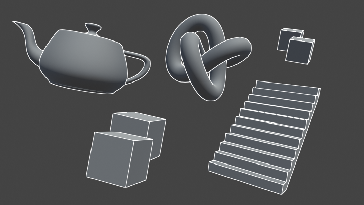
does anyone know where I could find a shader that shows a mesh's wireframe? I have been able to finagle something for primitives but for complex models it doesn't work so well..
If I want to use a transparent background PNG for a 2d particle emitter, and use the particle system to change the color of that sprite, what shader should I be choosing for that material? I can't seem to find one that works
I have a doubt, is there any way i can retrieve light probe data without lightmap? I am in a situation where I don't want lightmap once its baked, but need light probe
so that pre-baked light will affect dynamic object. (I am using light baked textures on objects for simulating light)
any use ComputeWorldSpacePosition from URP core library
and get wrong values ?
float3 ComputeWorldSpacePosition(float2 positionNDC, float deviceDepth, float4x4 invViewProjMatrix)
{
    float4 positionCS  = ComputeClipSpacePosition(positionNDC, deviceDepth);
    float4 hpositionWS = mul(invViewProjMatrix, positionCS);
    return hpositionWS.xyz / hpositionWS.w;
}
im passing in the UV coordatinte for positionNDC
[0,1]
device depth is the camera's depth buffer
Hey guys, here's a shot at multi-pass shaders with different shader models. I was trying to make a nice car shader:

What do you sayy?
How do I make particle impact events interact with a shader?
I'm attempting to make a shader that has this effect on the scene. Right now I just have a plane in front of my camera that this will be applied to. I've tried a few things and nothing is producing results even close to what I would expect, so clearly I have no idea how shadergraph nodes work.
My thought process is that I'd get the world position, get the distance from the camera position, and use this value to lerp between two colors (close/far) clamped to a max distance where everything is the far color. But I'm getting nowhere. What am I doing wrong?

How to access 1 side of the cube via shader graph? I am trying to color 2 sides
@rare charm use the depth buffer values to lerp between colors
@worthy meadow dot products of normal vector in world space with a vector such as (0,1,0) for up
question, does doing something like this eat up a lot of performance? im just shifting the screen texture by different amounts and then averaging them together to create a blur effect


https://forum.unity.com/threads/confused-on-ndc-space.1024414/
See post #2 by bglous, check your values against what he's saying.
Unity Forum
Hello,
From textbooks, NDC space is clip space / w. However, I found some weird code in Core.hlsl in package com.unity.render-pipelines.universal....
Shaders are the most difficult thing I've ever attempted to learn, because this doesn't seem to work either. Unless this isn't correct? It looks like it might make sense, but just makes everything white (color_fg is white, color_bg is black)

I'm looking to create an sdf for a dashed line, so far I'm pretty sure I need to generate something like this:

going from 0 to 1, its a line but at equal intervals it flattens out for a set width and then continues on its old path, can someone help me out with this?
make sure that you're using the transparent render mode, and that you have depth texture enabled in the render pipeline asset
mathematically, you essentially want:
currentInterval = floor(currentX / intervalWidth)
intervalStartHeight = currentInterval * intervalHeight  // This is the height if you're in a flat zone
slopeOffset = (currentX - lastIntervalX) * slope        // slope might be intervalHeight / intervalWidth?
Then depending on whether the current interval is even or odd, you want to either return intervalStartHeight or intervalStartHeight + slopeOffset
I think I got the graph wrong in the first pic, this is how it actually is supposed to look like.

where would I get interval height from? wouldn't it be the same as interval width?
if your line is x = y, then yes
so, for step function sections
you essentially need to calculate the height at the left and right sides
and then decide whether you're more than halfway through the current interval
and use either left or right depending
and for the sloped section
do the same as what I described above
this is currently my issue
floor(currentX / intervalWidth) * intervalWidth
not 100% sure of the floor syntax, I'm new to shaders
but that's the concept
round your position to an int
then multiply by width
for right side, use ceil instead
or add 1 to floor
sorry, floor * intervalWidth gives you the X value to evaluate your function at
so you'd need to multiply it by slope
which I guess is 1 in this case
floor(currentX / intervalWidth) what does this calculate?
it's confusing, because the entire graph is in the range of 0 to 1
that might be a bit off
I'm trying to get the number of intervals in from the left side
so if you're current value is 0.7 and your intervals are 0.25
you're in the 3rd interval
0-0.25, 0.25-0.5, 0.5-0.75
does that include the slope segment?
yes
I'm assuming the width of the slope segment is the same as the width of the non-slope segment
so even segments have a slope and odd segments are flat
nope, they can be different
they are supposed to be equally spaced from the center of the line
that doesn't uniquely determine their position
the non slope segments
if it was the slope sections, and we knew that they had endpoints at 0 and 1 then that would be enough information
how I did it before was with modulo operations
hmmm I guess if you also require that all slope sections are the same width it might determine it enough
so you say you have X non-slope sections of width dX and X + 1 slope sections of width dY, right?
oh, I was just using the calculus convention dx dy for something like "difference in X"
its just a width variable
oh ok
so you can look at pairs of segments
with width dX + dY
and say floor(currentX / (dX + dY)) is the number of slope/non-slope combinations from 0
so floor(currentX / (dX + dY)) * (dX + dY) = left side of the last slope section
then if that value is more than dY (slope width) less than currentX
you are in a slope section
ok it's starting to make sense
combinedIntervalWidth = widthSlope + widthNonSlope
currentCombinedInterval = floor(currentX / (combinedIntervalWidth))
currentIntervalStart = currentCombinedInterval * combinedIntervalWidth

distanceIntoCurrentInterval = currentX - currentIntervalStart
inSlopeSection = distanceIntoCurrentInterval < widthSlope ? 1 : 0
need more? I think that's the key gist of it
I'll digest what you wrote first and come back to it tomorrow
thanks for the help! I'll be sure to post a screenshot here if it works out
yeah, np
there's a lingering constraint on what widthSlope and widthNonSlope can be so that the total width equals 1, but that would come into play somewhere else not in this calculation
I do. Idk, maybe I'm approaching this the wrong way. Let's say I have a plane that acts like a filter. When that plane is in front of the camera it should render the depthmap of everything behind it. Kind of like night-vision but depth-vision instead. How do I go about this?
has anyone encountered a problem where shader graph stops displaying shader keywords in material gui? also funny thing happened where the keywords no longer have the green dot next to them.

right clicking the nodes and selecting "reset reference" fixed the issue. 😮

Quick question, how do you change the black background to be transparent?

Seems like you would need to connect the A output of "Sample Texture 2D" to the "Alpha" input of "Fragment". If this doesn't seem to work maybe the "Alpha Transparency" isn't set on the texture asset?
Oh yeah I just connected the Alpha & it worked, thanks!
is there documentation somewhere for the various hlsl files Unity provides as helpers for URP HLSLPROGRAM shaders, or is the current state of the art trolling through everything on the github and just looking around ? Something like https://docs.unity3d.com/2021.2/Documentation/Manual/SL-BuiltinIncludes.html and https://docs.unity3d.com/2021.2/Documentation/Manual/SL-BuiltinFunctions.html but for the URP package?
Hey there guys, so i've recently downloaded a 3D gun model for my vr game. However, I had found out that the model is only being displayed in one eye of the headset. Any solution to fix it?
The references for boolean keywords require ending in "_ON" to be exposed, resetting them properly automatically did that. If you're setting the keywords from C# too you may want to change them to something more readable though
Mostly just looking at the github. I've got this which compares some of the built-in functions to URP ones too : https://www.cyanilux.com/tutorials/urp-shader-code/#summary-functions
Hi, is there a way to get position of a projector or some local position relative to the projector in HDRP Decal Graph?
Hello, guys i have a shader found on youtube but it doesn't work properly.. when i increase the radius, texture doesn't change in the game.. in the inspector, the material preview it shows that the material texture changes but in the actual game it doesn't

this is the custom function code

You're properly updating the _PlayerPos and _Radius variable from script, right ?
Hey guys. I'm trying to set up a shader for my strategy game. I have created two textures, a lookup map that contains uv coordinates of a colormap and the colormap itself, which are sampled.
Works pretty well until now, but i realized some grey areas between the colors (the big grey line is a river and intended).
I'm pretty sure that in these areas the sampler interpolates over all colors in the color map between the specified coordinates. When there are two colors adjacent that are adjacent in the color map too, no grey areas are visible.
Is there a way to stop the shader from interpolating over the texture and just use "discrete points"? I already tried the point filter, but this only decreased the size of the grey areas.
this is the result with the grey areas in between

this is my current, simple shader graph

this is the (zoomed) result when i switch the filter mode to "linear"

Hey, how would we fill a mesh with colors based on different percentages ? I'm trying to avoid to use branches (not really optimized if I remind well) but can't figure which nodes to use
Here’s the car paint shader I am working on! Comments please 😊
Can someone help me with this shader issue im having? This is how it is supposed to look:

And this is how it is rendered:

I think it might have to do with the scripted rendering pipeline but i accidently clicked the error away so i have no idea on what to search for on google. normally i dont ask for help since google is enough most of the time.
That looks really good. My only suggestion would be to turn the light reflections down. It would appear that on certain colors it reflects way more than other colors.
Uuuhm after reinstalling the packages for shader graph and lightweight RP it somehow works now. So never mind. 🙂
I'm having a very concerning issue. My project looks perfect in the editor, but certain objects are not rendering in the Windows build. The objects that aren't rendering are Legacy Shaders/Transparent/Diffuse and Unlit/Texture. I made sure to include these in the "Always Included Shaders" and saving to asset, but no luck.
Thank you so much! I will note this down. But I am also confused because in games like NFS the cars are super reflective. At times so much that their base colour isn’t recognisable. So how do they manage such things? I want to work on games so please advise 😀
Here is what the object looks like in the editor, but it isn't rendering in the build. I'm a bit new to Unity, so I don't know if it's an easy fix or not.

My running theory is that these materials are not yet present in the scene until some scripts create them, so Unity doesn't include them when compiling. Hopefully that should be an easy fix.
Ok, the shader works in the build when I create the material in the editor. It seems that if the material is created in a script, it won't work in the build (even if that shader is present in the scene beforehand). I think a workaround will be to create each material manually in the editor and just assign them in the script. It's a bit tedious, but I think it should work.
Scratch that, figured it out! Apparently I need to assign the material from the script using gameObject.GetComponent<MeshRenderer>().sharedMaterial = material; instead of gameObject.GetComponent<MeshRenderer>().material = material;
so... I have a shader... and I never realized how cursed shaders can be
without shaders

with shaders

Is your landscape a single mesh? Are your colored regions sharing vertices between adjacent regions?
I notice there is an outline around the chin - I presume you are intending to add an outline around the character, and you have a shader which extrudes the mesh out according to the normals and colors it darker to create a hull outline? If so, I think that shader is probably also moving the vertices inside the mouth, and creating that weird inside out artefact
Yes, it is a single mesh (an overlay for the landscape). And yes, the vertices are shared. I created a grid of vertices and just set the positions, normals and triangles. I create both textures by code and they seem to be alright
this is how i generate both maps

I think the only issue is the blending. This should be because I "sample Texture2d" which creates the interpolation between vertices, but I couldn't figure an alternative out yet 😄
(in the code the line for setting v is missing, however it doesn't make a difference as i have not enough colors in the color map to reach a v>0 yet)
triangles and vertices on my mesh

I have a cloud shadow effect linked to noise and time, I want it to only play at certain times, ie not during the night, how would be a good way to link up that logic from a script
I was thinking something around the lines of smooth-steping between the full shadow and a white image, with t being provided by a script but I couldn't get it to work properly
what I mean is - if you don't want blending across the face, you can just double up the vertices. Instead of sharing vertices between triangles, just give each triangle it's own set. it's (marginally) less efficient, but it doesn't look like this is an extreme vertex count anyway

@wraith inlet got my dashed line sdf mostly working now with some small modifications to what you suggested

turns out the length isn't always from 0 to 1 though
so I'll have to account for that too
i will try this for now, thank you very much 🙂
update: got it to work now, needed to bypass sRGB at texture creation ("Texture2D colorMapTexture = new Texture2D(256, 256, TextureFormat.RGBA32, false, false);"), now everything is crisp 🙂
Do you want it to be super reflective or not?
https://www.youtube.com/watch?v=Lm5tRVNQxFs&list=PLgemWy0Blp3rKwG2WrW5__J8CNWID0YbV&index=4 I was trying to recreate this effect, I already have the cel shading and isometric camera effect, but I can't figure out how to get this pixel art effect working properly, can anyone help?
For pixel art effect you could just add a low res render texture with no filtering to the camera
I already downsized it to 640x300 (16:9 ratio) and resized it back up bit it still looks off, i wanted to try to make the effect with shaders, combining it with my cel shading graph
@limber mica this might be of use?

Download the shader here https://alexanderameye.github.io/pixelation
You can see more of my work here https://twitter.com/alexanderameye
is anybody here?
can I ask a question about transparent shaders?
I use fade for transparent but the surface is not receiving shadows... why?

anyone have any success with the SDF tool ?
There is more to it than that if you want convincing pixel art - the style also often employs (i) a prominent silhouette rimlight or dark outline, (ii) cel shading, (iii) dithering (but that is very style dependent), (iv) edge detection based outlines. For the one in @limber mica 's video, you could look at doing an edge detection pass and lightening pixels on a normal/edge
Also, downscaling the resolution can have unintended side effects - it can make the motion quite clunky, as you are limited to moving objects at the render target resolution instead of the screen resolution (you also usually need to clamp the objects position to the render target pixels to remove pixel creep)
There are screen-space methods that avoid this, eg by rendering the object in a dithered pattern and filling out the pattern at the post processing stage to produce pixelated objects
See attempt #3 here: https://medium.com/@elliotbentine/pixelizing-3d-objects-b55ec33328f1
I already have cel-shading and i'm trying to add a good edge detection outline right now, can you point me towards a tutorial for the rest of this
This one looks like it covers the concepts in detail: https://roystan.net/articles/outline-shader.html?fbclid=IwAR26tdfinzWb-BeAy2yOXpFRKdG9VrWmvhqc0iBNNL5jBbPBpW3wt606fbw you probably need to consider differences in depth, differences in normals, possibly differences in color
Learn to write an outline edge detection shader for Unity engine, integrated with the post-processing stack. This effect is especially popular as a compliment to toon shading, or in CAD and architectural rendering.
(I also usually add an extra pass to render object IDs to a buffer so I can differentiate between different objects)
thanks for the help. I'll check it out in a bit :D
Does anyone know why i can't connect this notes?

The Sample Texture 2D nodes only work in the fragment stage. Vertex ports would need to use Sample Texture 2D LOD instead
thank you, it works
How do you get their IDs?
Does anyone know if you can edit this script (found in the Unity provided C# source code for URP) for adding new types of post processing? I want to make a post processing volume that allows me to change what a color looks like (change the color red to look like green for example)

and i see this same script is setting a materials properties, not sure where that mat is
I output to a second render target with a custom pass defined for objects I want to outline, using a custom LightMode, and this custom pass puts out per object metadata (used for ID, outline control, some other stuff). https://forum.unity.com/threads/multipass-shaders-in-urp.864187/#post-7027999
having a (low depth) buffer filled with different object IDs is nice for outlining, it's how I do the per-object outlines in my asset
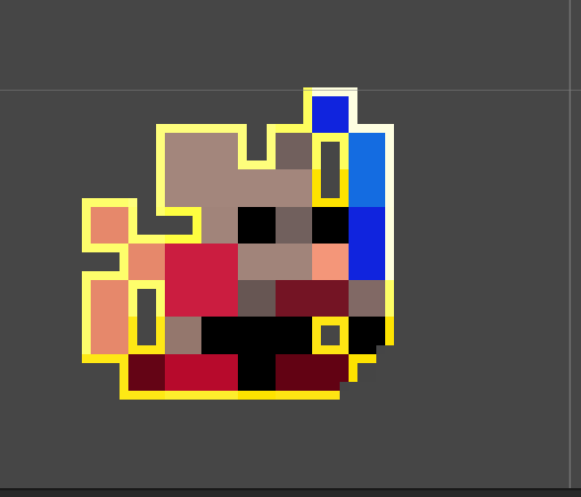
Hi, Im trying to make an outline of my sprite here and Im having troubles. I am currently got it to this point but am unsure of why the bottom right pixels get cut off

I am rougly following this tutorial to make an outline

Thanks to NVIDIA for sponsoring!
Learn more about NVIDIA Studio► https://nvda.ws/38AaA8K
Razer Blade Studio laptops► https://www.razer.com/studio
In this video we create outline effect using 2D Shader Graph!
● Learn more about 2D Shader Graph: https://youtu.be/5dzGj9k8Qy8
● 2D Glow Tutorial: https://youtu.be/WiDVoj5VQ4c
● Get Gothicvania Ch...
The thing I am trying to change is to adapt this outline to also include the corners.


having this "pixel" filled with the shader too. Currently I am doing for the offset of the outline:
(0.01, 0.01), (-0.01, -0.01), (-0.01, 0.01), (0.01, -0.01),
any help or pointers in the right direction would be greatly appreciated 😄
update: I am an idiot and forgot to link a node.


works great now, thank you everyone that read through my spiel 🙂
hey everyone
is there a way to make a custom pass / volume not run in editor window
only game window
Hello, I just recently started using HDRP and I am having issues with emission. I use Autodesk Interactive shader, but for some reason when I put the emission texture and I enable "Use Emission", the emission is not showing. I am unable to get it working... Is there some additional option that I need to enable? I have increased the intensity as well, but still nothing
This isn't really a shader question, you'd be better suited for #archived-hdrp . That said: what do you mean by "the emission is not showing"? Can you provide a picture of what you see, vs an example of what you expect to see?
You may be missing a bloom post-processing effect
I think you can disable post processing through the buttons on the bar at the top of the window

Hey, shader noob here looking for some help with optimization. I've written this 4D Voronoi noise function, but it's very slow, and I don't really understand why. Is there a way to make it significantly faster, or am I out of luck due to the nested for loops required?
I'm trying to re-purpose the Valve/VR/Silhouette "outlining" shader (from SteamVR Plugin) to highlight one or more objects in my scene simultaneously with different colors. To my surprise, the highlights all combine together when the objects overlap. Even when I use different shaders (duplicated the shader) and materials, the outlines merge together. For this to be happening, there must be some communication between the different shaders/materials/rendering meshes. Any idea how I can prevent this from happening?
Does anyone know how to create a Depth Mask Shader in HDRP?
Are the materials all using the same buffer?
There's a Scene Depth shader graph node, you could try looking at the code it generates
where is that specified? Is that Render Queue?
I found that I can move one outline in front of the other by changing the Render Queue, but I can't make them both draw in the same area
Orange means object is selected (trigger pressed) and Green means laser is pointing to it. The two somehow combine into one outline. By changing the queue, I can change which one is in front vs. back.
is there a tutorial about creating arrow like this
'

@grand jolt could you help me creating these with a shader?
@surreal coral use a flipbook animation
the easiest way would be to draw it and then animate it in shadergraph

I go over how to use Unity's Flipbook in the HDR Shader Graph. This will show you how to use your own sprite sheets to make animated textures for your own projects. You can use these steps to improve on the methods shown as I go over some of the basics.
No coding was used in the making of this video. I show how to animate the tile amount throu...
ok thx
do you have a link to the shader?
How do i make the tail that disapear in 2d also dispear in 3d (pic 1 is 2d and pic 2 is 3d) without deleating the tail?Is there any way to make it fully transperant?


it disappears in 2D because the mesh is flat and being seen edge-on
note that if you had a light and cast a shadow the wings would cast a shadow
easiest way is to probably modify the alpha channel of the albedo texture and use alpha clip to not render the wings
Is it common in a shader to store kernels in actual matrix types? Such as for blurring or edge detection
Elliot, you might know this?
I don't I'm afraid, I'm not sure what the overheads are for matrix types and fortunately I've been able to avoid them so far (so far a first order gradient has been fine for edge detection if you combine results from both a normals and depth test - but I'll give a caveat that I work mostly in iso and I expect tests are easier than in perspective)
I want to take a plane, slide it in front of my camera, and have it render the depthmap of everything behind it. Kind of like a night-vision filter but instead a depth-vision filter. I've tried a few things and I can't get it to work right. How can I accomplish this?
I'm not great at math so i can't figure out why StartFrame variable isn't doing anything. I just want the animation to start at a different frame.

Does anyone know (if it's possible) in Shader Graph to project a texture to view, or how to say? Specifically taking a renderTexture from a camera and get it's UV on a material to match up exactly with the view it captures? EDIT: Never mind, I just confused myself trying to use position and view instead of screen space nodes
You have to put your material in the Transparent render queue - I'm pretty sure Cyan's depth tutorials might actually do this and could be a good starting point (https://www.cyanilux.com/tutorials/depth/) - did you see this resource already? If so, ask more questions on where you got stuck
do you just see it constantly looping? you are probably changing the start but it doesnt matter because you are still watching the loop?
Its meant to loop. I just don't know how to make it loop back to the desired starting frame that i set. It always loops back to the first frame.
I'll probably need to relearn math again.
I think the problem I'm having is that it gets the depth of the object rather than the depth of whatever is behind it.
Is there a reason you're using a plane instead of making it a camera effect?
Can camera effects be applied to a portion of the screen?
yeah
I think I gave up on them because doing a blit with urp ended up being a bit of a pain
That's why Elliot says to make it transparent, so it won't write to the depth buffer
But that didn't have any actual effect
Check the universal renderer examples GitHub repo, they have a full screen blit
And then in the material that's used during the blit, use a shader that includes 'DeclareDepthTexture.hlsl' and use 'SampleSceneDepth(uv)' to sample the depth texture and return it in the frag function
What does that look like in shadergraph?
Because the scene depth node doesn't seem to do what I think it does
Uh yeah the scene depth node should do that, if you have enabled the depth texture in your render pipeline asset
A simple shadergraph material that is transparent and outputs the scene depth node to color, applied to a quad/plane, should show the depth texture without doing anything extra

Bear in mind that scene depth values can look weird if you output them directly to the color channels. You might want to use map before to change them to 0->1 over some distance. Also bear in mind that the scaling is different for perspective versus orthographic (probably easier to test it in orthographic, where the values are linear and somewhat easier to understand)
you currently have (FPS * Time + Start Frame) % EndFrame - I think what you want is StartFrame + (FPS * time % (EndFrame-StartFrame))
possibly also a round


base color is only float(3)
there's a separate alpha channel
notice it's hardcoded to 1 right now
yeah but that alpha controls the whole sprite?
split your Out(4) into rgb and a
Before then the vertex and fragment node was combined too
Yeah thanks
Then its gone 😦
Hm. Have to tinker around thanks
Like that ?

there might be easier ways but yeah
Then it just vanishes away
🤔
Thats weird
wdym by that? no alpha?
you might have to change the transparency mode or the alpha clip threshold
is it possible to get unity built-in shader variables?
guys, I am a bit confused about using normals in surface shader and custom vertex function. If I directly get the normals from appdata_full and provide it to the surface shader, heres what I get:

whereas the expectedOutput generally is:

@quaint coyote can you post the vertex shader code

@white ore yes, it should be in an .hlsl file in URP / HDRP package. you can open it up and see all the variables
or check the unity manual
@quaint coyote why is it being multipied by MV matrix not MVP
@heavy stirrup so I wanted to get the vertex posi in view space. but that shouldnt affect the normals right?
it should because that changes where the fragments are placed on the screen
the vPos is another variable in the struct. I am not modifying the original vertex position.
its just a place holder for view space vertex position
also, I just tried changing it to MVP, but the normals are still the same
😦
can you post the full code
sure
thanks, but how can i get the exact value?
depends
you could probably just upload it to a compute buffer in a compute shader, and read it back on the cpu side
if it's float4 values, like the ScreenSize for example
you can draw the values to the screen, dvided by a certain rangeg
and then inspect the color and remap it
@white ore
so here's what I was doing wrong:
I was trying to map the Input structs normals to surfaceStructs normals. Why would I do that?
Hey guys ... i got a small issue in unity 2021 version where i want to increase the light emission on my light materials ... in older versions i used to show a slider for that now it doesn't how can i do that ? also how can i combine baked lighting and still have light effecting non-static objects ?
Thank you! It worked!

I am using URP with post process and bloom and the scene view (on specific zoom levels) does this

one step zoomed out

few steps in

few in more

It doesnt happen in-game. Is that a bug or something?
seems strange, if you don't change the zoom but instead change the scale of the sprite in the scene view (so it fills the same area of the viewport) does it happen?
Yeah
Zooming out and stretching it achievs the same effect

But only in the scene view
There's a function for it. Don't just assign it.
o.worldNormal = UnityObjectToWorldNormal(normal);
in your custom vert()
Thank you so much 😊
can someone help me? i want create a shader that combine all different sprite renders "parts" of characters animated via 2d animation similar to what sprite group do but with alpha control without looking like this. can someone give me a direction how to achieve the correct alpha effect ?

try using an Opaque material (rather than transparent) and using alpha clip, so you can benefit from depth testing. Then, arrange the sprite 'layers' at different distances from the camera
the problem is that i have multiples characters in scene..
that why i'm looking into using a custom sprite shader that replicate the similar effect of sprite group combine and them in the result render change de alpha
in which case you might want to do it through draw order/render queue instead, to eg draw the feet, then the legs, then the shorts, etc
hum.. thanks i'll take a look at that 😄
I have a question about fresnel implementation. I have gone through the Schlick implementation. But most of the examples I see use view direction and light direction
When I use that, I don’t get the nice rim light. I have to use the normal for calculating the fresnel
I'm looking to pay someone a bit for help with affine / projective UV mapping in a unity shader, as detailed in this post:
https://gamedev.stackexchange.com/questions/148082/how-can-i-fix-zig-zagging-uv-mapping-artifacts-on-a-generated-mesh-that-tapers/148102#148102
If anyone is available to help, please message me.

Game Development Stack Exchange
I am creating a procedural mesh based on a curve and the size of the mesh gets smaller throughout the curve as you see below.
And the problem is UV gets zig-zagged as the size changes (it works
They literally gave you the code in that post. Does it not work?
Not trying to be sarcastic. But what's not working?
I haven't been able to make it work, and my understanding of shaders is limited.
It seems like it shouldn't be too complicated, but I just haven't been able to make it work. I could provide a sample geometry and texture.


I have a ring around my origin that's extending to the horizon basically, you can see how the UVs are warping the projected texture

Wireframe looks like that
Oh. What you might want to try is triplanar mapping (you're only really worried about 1 direction though). So it takes a texture and spreads it across using worldspace. If you're using shader graph, there's even a node for it.
Or just google "triplanar texturing unity". You don't even need UV's! 😉
Just an idea.....
I want multiple shaders to all use the same 1 method, so I'm thinking of writing a cg file for it? Never done that before though so I have some questions:
1 - Is this the right thing to do?
2 - If so, is there a way to edit the variables inside the cg file at runtime
does anyone know how to create a shader setup for this senario on a textmesh pro object without faking the background?

what happened to my preview.......?

oh nvm I wasn't in urp
How do I make a volumetric cloud shader that surrounds the player?
I don't want it to be limited by a bounding box in the sky
I want the player to be able to walk through soft volumetric clouds
Guys a quick question on fresnel specifically about Schlick implementation. Does half way vector in anyway use normals for calculation ?
If I just use view and light dir, then I don’t ge the actual fresnel effect at all
it's just a squashed image with black tint color
You can define functions within your extra files that you then pass variables to. You can define constants in the files, and variables within the local scope of the functions
Either use 3d objects and render them to look like sprites or if you prefer a 2d workflow use an alpha clipped sprite. Materials must be opaque to be able to cast shadows
Ahh my bad, missed the unity 2d specification! In which case probably squashed and tinted is the way to go as suggested above
I think you can skew the image by displacing the vertices in local x position based on their local y position.
Can anyone please help me to get the under side of this cloak showing?
I am using this "PSX Shader"
https://github.com/dsoft20/psx_retroshader

This is how it should look

You could add cull off but I'd suggest you edit the mesh it self and add normal-flipped cape
Does this mean duplicate the cape and invert it?
I added cull off to the shader and now this happens

Another question I have about the psx shader I'm using is why I can't add the transparent map (down the bottom) to my model in order to get the tattered cloak effect.
Sorry for these questions guys. I appreciate what you're doing here and while I'm not a shader person myself, once I've ironed out these issues I doubt I'll be asking many more questions

There's a normal for every face of triangles when you're creating the model. He's saying that you've got the normals inverted for the cape. The forward direction for the cape should be towards the front of the character where's you've got it going away from the character. Back culling would then only show the objects we're assuming to be facing a particular direction. We're not suggesting you to duplicate the cape, we're suggesting you to flip the normals (frontal direction that every triangle has that determines which way is front/back) for the cape.
You mean like this?

Wouldn't that just make the cloak invisible from the back instead of the "inside"?
Like this

So it's the same issue it's just that now it's in reverse

I'm not an artist but I do understand renderers and how they work with culling. When you're in front of the model all triangles facing the camera are rendered whereas triangles facing away are not. When you're being, the opposite would occur; looking at an objects back, the front half are not rendered at all.
Where facing is determined by the normal.
What did you reverse, the entire model?
Just for clarity, we were only referring to the cape.
That's correct. I reversed the normals of the cape. Take note of the "double sided" option I've highlighted to the right in Maya. This is unchecked, so now only the forward facing normals are being rendered in Maya (just like in Unity with the PSX shader)

Now the same image with the "double sided" option checked on

It's now being rendered from the front and the back, and my question is how I can get this same result in the Unity engine
I understand there are double sided shaders on the Unity asset store, but it's important to me that I get this result with the PSX shader specifically
Hey guys, I'm getting an annoying problem using shadergraph custom function nodes. I have a bunch of parameters in the function, I've specified them in the unity wrapper (you'd think they'd do that automatically) and it's all compiling ok but no input appears.
No 'eyeLidao'

I think there's an option either on the material or mesh renderer for double sided
In the end, I recreated the custom function instance and it worked. That seems to be a bug, unless I missed something obvious: some cached copy of the function interface hanging around or something? It's a bit of a black box.
A silly but practical option might be to just duplicate all those vertices and flip the normals on one of the copies. Only one set will ever render anyways, so you shouldn't need to worry about any z-fighting issues.
hey guys do you knows how i can make sure the mask in an image with a custom shadergraph material keeps working? top image is with a material and bottom one is without. probably im forgetting something simple in the shadergraph but i cant figure it out.

hey its that guy who does the videos


it won't fade properly
Unless I'm mistaken, the UI masking uses stencil operations which aren't available in SG. You may have to edit the generated code to add it in. The built-in UI shader might give some hints to the property names / stencil pass : https://github.com/TwoTailsGames/Unity-Built-in-Shaders/blob/master/DefaultResourcesExtra/UI/UI-Default.shader
The Vector4 "Color" port on the master node was converted to a Vector3 "Base Color" (RGB) port and Vector1 "Alpha" port on the master stack. Connecting your final Vector4 up to the Vector1 port will just use the first (red) channel though. You would need to Split it and use the A output.
ohhh ok I didn't realize it uses the first channel.. I think I got it now, thanks
Hi guys 🙂 I have recently upgraded my shader to URP and now the material previews (not the materials themselves) are showing pink in the asset folder. The materials are working fine so I wonder how I can update the previews? When I create a new material from the shader the material previews are working fine.

Left one is newly created, the others are from the materials prior to updating to URP
Hey all, here's my implementation of ggx with some fresnel. Looking forward to add reflections to this shader. Any pointers/tips?
https://www.linkedin.com/posts/videep_wip-unity-shader-activity-6825469763024756737-uEqB

[#WIP] After quite some time, I have been able to take out some quality time to spend with #unity
Since I've read about the physically based lighting models...
here's my new car-paint(without flakes):

Iam trying to use the property _StencilComp in a shader.
Like this:
[Enum(Rendering.CompareFunction)] _StencilComp("StencilComp", Int) = 8
...
            Stencil {
                Ref 1
                Comp [_StencilComp]
            }
If i set Comp to always it works perfectly fine, but using the property does not work. Any idea?
Nevermind...found the issue, it was set in the material 😬
Do you know any books or other resources for learning shaders?
Is there a way to toggle a mulit_compile through a script?
Use material.EnableKeyword("KEYWORD") (also DisableKeyword) https://docs.unity3d.com/ScriptReference/Material.EnableKeyword.html
Thank you, that is just what I needed
Anyone have good familiarity with the deferred renderer in URP? I'm trying to clamp my light influence in the fragment shader to a max of half3(1.0, 1.0, 1.0), but due to the way that deferred shading works, it keeps adding each light on top of the previous one. This makes it hard to limit the contribution. With the forward renderer, one can simply calculate the light contribution for the whole fragment, clamp it to white and it will never go over.
hey guys I made a material with a custom shader, I am having the problem of not being able to change its color, it remains purple
purple, or pink? pink indicates a compiler error with the shader. click on the .shader in the inspector to see the errors.
paste a screenshot of the inspector with your shader highlighted.
oh wait I re did the shader and got
Shader warning in 'Master': implicit truncation of vector type at line 281 (on d3d11)
😉
what does this mean?
post the line of code.
check on line 281 of the shader you wrote. you should start there.
my actions were: right click create standard shader
only have 53 lines of code
lel
if you double click the error, which file opens up?
ah ok, it shows Master(shader) in inspector
click were is says compile and show code?
no. click on the error with the red question mark.

that's a warning. it's not an error. and yes, you cannot use standard shaders with URP. You have to use Lit (PBR), SimpleLit (BlinnPhong) and Unlit.
wtf are these and how do i get rid of it

@mystic dagger just add your Library folder to your .gitignore. It doesn't need to be committed. it can be rebuilt on each computer locally.
I didn't add the .gitignore until after I had the project set up
that's fine. you'll add the Library folder, and it will show all those files as deleted. Stage and commit. And they won't be in your repo anymore.
ok, but I have the .gitignore and it's still happening
does it matter what it's called?

it's preventing me from pushing changes :[
It should be labeled just .gitignore and it should be in the root folder of your repo.
will try that, thanks
Hello Shader heads
Got a question
So Im using the Alembic/ Overlay shader to show Vertex colors on an Alembic animation , The problem is that it seems to be an Unlit shader - but I want to use it with DXR in HDRP
is there a way to pull the vertex color but put in to an HDRP Lit shader?
into the albedo channel of course

IDK of any restriction in the HDRP that says you cannot use vertex colors with a lit graph...but I don't know HDRP well either. So grain of salt. What you do with the values is what you "code" in the graph.
The vert colors are part of the mesh data.
Any reason why Standard Surface shaders can't sample CubemapArrays?
hey does anyone know how to make a local variable
in shader graph?
i want a modded time variable that is time * .125 for example
and setting it to a variable like the blackboard properties
@heavy stirrup Right Click->Create Node->Input->Basic (for input)
I guess you're basically left with the nodes output to track your variables (for output)
Hi. I did some generation of meshes using scripts in the past and am now aware of how inefficient and GCing the code is. I suspect I could do a lot of it using a shader. I am not really sure what kind is appropriate or pros/cons of use of shaders for this sort of application. Has anyone got any suggestions on what to read up on?
Hey there,
I have a shader which has one parameter, I want to have 2 parameters instead, one when looking from downside of the plane and one when looking from upside. How can I handle this situation ?
hey guys is it possible to know a vertice height in a shader?
I am asking this because I got a shader to make waves and I wanted to know the vertex position in the shader so I could float an object
Whatever formula you're using to determine the height of the vertices, you need to also calculate it in code to determine the height.
For example, if you're using a gerstner wave formula, you would run the same formula at that point of space of your object, to determine what the height would be at.
ok you are confirming that I was thinking that I needed to calculate it again in code
to bad that I dont understand nothing of this shader graph, I am using a gradient noise, I guess that it will be dificult with that right?
You should definitely look up gerstner waves. It's a mathematical approach to waves which means it's pretty easy to port it to C# sampling for height.
Or, if you just need basic bouyancy, this (now free) asset is really good. (URP)
https://assetstore.unity.com/packages/vfx/shaders/stylized-water-for-urp-162025

Add depth to your next project with Stylized Water For URP from Alexander Ameye. Find this & more VFX Shaders on the Unity Asset Store.
wow thanks
I dont even have to worrie about it
its already done for free
lel
my head was burning with this shit
Hello! how can i have mirror UVs on the other side of the sprite on URP shader graph? (i will show how it's working currently with a test image)
this is the front side


this is the back side
but i'd like to get it lit like the front side
to seem like it just flipped
(i'm using a lit shader, not a sprite lit)
How’s this for a mobile game?

solved my problem, heres the solution for Shader Graph Mirror Normals on the Backface for a 2D Sprite so people can search (don't mind the test image i used it's a meme):

Based on this post here: https://forum.unity.com/threads/shader-graph-lwrp-cant-use-flipped-normals.646675/

Unity Forum
Hello!
I'm currently following this ([MEDIA]) tutorial by Brackeys. The only difference, I think, between his and my setup, is that I'm using the LWRP...
I do it like @tame topaz mentioned, gerstner waves in vertex shader and a recreation in c# for buoyancy
There you go, the asset creator himself. 😛
Has anyone figured out a functioning version of the Nature/Soft Occlusion shader for HDRP? Seems like a huge oversight that this doesn't function, and does not appear to be automatically upgraded:

Deleted my question. Of course I can go without an answer for days but then the moment I decide to ask Discord is the moment that I find the solution lmao
does anybody know how to get the relative location on a sprite in a shader?
like a map from (0,0) to (1,1) but on the individual sprite itself not the whole atlas
I had a solution but then it broke and I can't fix it, something to do with pivot points?
I can show you the code but I think it would be easiest if somebody could tell me how to do it in general this feels like something somebody would use alot
Something is already mapping the flipbook to the UV's 0-1 values.
Basically it's % through your range. So (current-start)/(end - start).
If you want it relative to some pivot point, you're using a non-UV coordinate system, perhaps -1 to 1 or -.5 to .5, IDK. So you'll have to translate that.
ok it has nothing to do with pivot points
I swear this should be really simple but its just not working no matter what I do
Im inputing the position and scale of the sprite to the material
which is in UV space
then I just divide the uv by the scale and the subtract the position
but that just doesn't work??
I can show code if thats helpful
Let's just deal with on coordinate. The x. Y will be similar.
wait now its doing different things each time I run the scene
there must be a different problem
So if your sprite is at .2 thru .4 in the atlas.
Your re-mapped value is a range of .2
So if you're at .25, your new 0-1 UV space logical coordinate is:
no I get the math I think something else is broken because this was working fine before
thanks for the help tho
IDK then. You'll have to debug.
yeah
its feeding in different values each time
do you know what could possibly be the issue?

is there some weird unity optimizer that changes sprite atlases?
this isn't even me restarting the scene im just respawning everything
sometimes _Pos gets set to (0.1,0.2) and sometimes it gets set to (0.5,0) (correctly)
verified with a debug in c#
in fact its the Vector2 p1 not even the shader variable
I think I fixed it, it has something to do with getting a sprites bounds right when an object spawns
It says I don't have a _MainTex property but I do

the error says "gradient" is the one missing
yea just ask the question
Hi everyone!
I wanted to ask if someone knows about how the detail map is used in the hdrp default lit shader, because I want to make a shader in the builtin render pipeline which supports basic properties of the hdrp lit shader, for backporting purposes.
This page of the documentation lays out what channel information mask map and detail contain
https://docs.unity3d.com/Packages/com.unity.render-pipelines.high-definition@7.1/manual/Mask-Map-and-Detail-Map.html
but I'd be interested in "how" the channels are used in the shader. I tried to look for through the shader source code, but it was so convoluted, with 16 or 17 passes and a ton of file includes.
For example:
The mask map blue channel is the masking value for the detail map.
- how are existing shader properties and mask map properties combined based on it?
- how are the scale parameters uses (_DetailAlbedoScale etc.), do they scale the sampled detail map value or are they used to scale the uv before sampling the detail mask?
- the detail mask contains green and red color channel information for a detail normal, but how do I get the blue value? At the moment I assume that the all normal values are normalized, so I calculate the blue channel value from the red and green channel and an assumed final normal vector magnitude of 1.
- The red channel of the detail mask stores the albedo greyscale, but how is that information combined with the base albedo map to arrive at the final albedo color?
I also made a forum post at the end of a related thread that describes what I wanna do in more detail, with current shader code.
https://forum.unity.com/threads/standard-shader-using-hdrp-maps.541352/
Thanks
Unity Forum
Hello all. I've been doing a lot of testing going back and forth between Standard render pipeline and HDRP so I wrote two versions of the Standard...
Hey uh, if I'm not missing something obvious I might be in dire need of a matrix math shader mega wizard, because this seems baffling to me. - Experimenting with water reflection tactics; I'm doing some world position vertex transformation shenanigans to flip sprites upside down along an origin at their feet, problem was they couldn't face camera so I trial-and-error'd myself a 4x4 matrix on top to bend it back over a bit. At first it seemed to work perfectly but at some strange camera angles the meshes simply go mental, and what's stranger is that proximity of other meshes nearby affects whether or not this happens? I do not understand math or matrixes at all, but I got so close with results so bizarre I have to ask for an explanation or advice or anything. Here is a video as well https://www.youtube.com/watch?v=OfrFmkqrspw Most of the focus is on the window to the right


How does the proximity of a mesh affect how all meshes of the same shader project their vertices? Math is crazy.
if using URP I cannot create standard surface shaders?
can anyone recommend a realistic water shader with flowing water for a river that works with an orthgraphic cam in URP 2020 on android? Or does anyone know how to make the Orthographic Cam use Logarithmic depth instead of Linear?
is there a way to make the shader not visible were an object is in touch with it?
I am trying to make water shader not get inside my boat
is is possible to make some sort of boolean cut? like not render the shader or make it transparent inside the area which an object is touching it?
No, only shaders under the URP category
@meager zinc , you could work with or look into the stencil buffer.
Something like: boat has to render before the water, the boat will set for example a certain bit in the stencil buffer.
the water takes a stencil reference value and make certain comparisons with it, and will not be drawn when the reference value has a certain bit set for example
https://www.youtube.com/watch?v=AATjjduNUAU
https://www.youtube.com/watch?v=-NB2TR8IjE8

A video from my Unity Shader course available on Udemy. Get the full course for a great discount by following this link http://niklever.com/courses .
The resources for the course including over 70 custom shaders are available at https://github.com/NikLever/UnityShaders .

Tutorial going over the core concepts and syntax for using the stencil buffer in Unity shaders.
Here is the full reference: https://docs.unity3d.com/Manual/SL-Stencil.html
@dim sequoia but this is not compatible with urp right?
the way it is described in this video, it's for shaderlab (built in), but the concept stays the same
urp seems to have a stencil shader feature too
https://docs.unity3d.com/Packages/com.unity.render-pipelines.universal@8.3/manual/urp-renderer-feature.html
but I didn't really use urp so far so I can't tell you how it works
hey all, is there some shader magic I can use to force an object to render over another (but not over anything infront of it) - I have a clipping issue with a quad parented to a pivot and it rotates to face the camera but due to this sometimes it clips in to walls technically behind it
How do I like move multiple connections from one output to another at once?

Also, another question: I have a channel packed heightmap (its in the B channel).
How would I extract it to use it with the parallax node(s)?

Lastly how do you create material instances?
I have a shader that pulsates a texture emissiveness for use as a lantern suface.
But now all lanterns in the world pulsate at the exact same time. I would like to offset the pulsing based on the objects position in the world but i dont know how to do this.
I tried adding an offset to the sinus time with the world position but this does nothing

You can't connect 2 outputs, is that what you're trying to do?
Maybe I cant, but Idk how to grab multiple connections at all atm 😄 Whats the shortcut?
Im also curious, how would I obtain a 2-float UV map?
Like this or?

Yeah looks good, or instead of the combine just a vector 2 node I think, but also if you put a vector4 output into a vector2 input it will use the XY components anyways I think so you can plug the uv output directly into the input
(also, is there a math node with factor? Im thinking like a combination of say multiply, divide, add, power (Etc) and a lerp node) But maybe that isnt a thing?
Im thinking of Blenders MixRGB if anyone is familiar
Drag a selection box over them first and you can move multiple outputs to a different port
And yeah, that sounds like the Blend node
Use the Position output from the Object node. Take the X and Z (or add the Y somewhere) and use it as a seed for the Random Range.
To change the phase of the wave you'll also need to use the Time output and handle the Sine yourself, with the offset (random value) added.
You might need to change it to the green channel, as I think that's what the parallax mapping uses.
I dont understand the phase of the wave part and my own sine. im pretty unexperienced with the shader graph.
is this on the right track?

I think i did it!

it works


Also flickers when i move the camera
Hey guys i made my own ocean shader that has a foam feature created with the depth buffer
but i noticed something when i was messing around, it appears that if theres an object in front of the ocean theres this white outline thats pretty annoying

Im thinking its something to do with the depth buffer
but i dont have an idea on how to fix it
try turning on antialiasing
I made it in shadergraph btw heres the snippet

output goes into basecolor node output
How’s the car paint 🎨?

Has anyone managed to get a Toonshader going with URP?

Short and sweet shader tutorials.
Anyone here know how to get data back from a compute shader to the CPU asynchronously, the docs are really bad for it
very good!
is there a way to get depth masks to work with URP? im trying the
        ColorMask 0
        ZWrite On
``` method, but it seems like it's not getting cleared every frame
currently using URP 12 on Unity 2021.2.0b4


found a workaround by clipping based on world position in the shader
actually, nevermind
since it's just a simple light map, i replaced the material with unlit
instead of sprite unlit
changed surface mode to transparent, and now it works
Can opaque shader graph with alpha from texture even cast shadow somehow?

I can make standard URP simple lit shader cast shadows, but have no idea why it doesn't work on custom shader

Oh nevermind it's just a bug with a simple solution

if your wanting to do it with custom lighting you need to enable some keywords
I'd advise checking out Cyan's blog or this git which has good examples
https://github.com/Cyanilux/URP_ShaderGraphCustomLighting

GitHub
Some custom lighting functions/sub-graphs for Shader Graph, Universal Render Pipeline - GitHub - Cyanilux/URP_ShaderGraphCustomLighting: Some custom lighting functions/sub-graphs for Shader Graph, ...
Welp, I'm already using them :)
Shadow casting is usually handled automatically by shader graph, even when unlit (unless it's been changed in v12)
I would like to make a specific shader queue close objects first rather than far ones.
not a shader question per se...
but does anyone know how unity draws the skybox before the cams (e.g. so clearflags & dontclear lets you see bits of sky)?
I've tried Graphics.DrawMesh(), setting up a command buffer, using onPreCull, OnPreRender, etc, but it either doesn't draw, draws on top of everything, or throws an error in some cases due to the camera having already culled
AFAIK, the rendering order is Opaque (front-to-back) > Skybox > Transparent (painter's algo), Unity draws the skybox where the depth has not been set during the Opaque queue
What are you trying to achieve in layman's terms?
cheers
essentially just showing a draw in roughly where unity would do the CameraEvent.AfterSkybox event
e.g. a single call skybox
(In the meanwhile, here's my question for the channel) Screen-Space Sobel filters through Renderer Features: is a multi-pass approach more performing compared to a single pass convolution?
the skybox should be already a single call, unless you mean "I want to draw a single inverted cube/sphere mesh which should show my custom skybox"
yeah, the later
so the problem is that unity's own skyboxes are 6 draw calls
you can add a great big inverted box over your scene, but then when you think about it, pythagora's theorem, when you're looking at the corners, that's how long your far clip should be.
then you look at a flat part in the middle, and suddenly you're drawing (sqrt(2) - 1) * farClipDistance extra
so I tried doing a no z clip shader, metal doesn't seem to like it. cannot get metal to play nice on the iDevices (android's breezy, no issues)
so then I thought, try to inject a draw around the same time unity would draw the skybox anyway
just throw together a matrix, give it the mesh and material... done..
but I can't seem to get it to draw a damn thing 😄
( I know the matrix works, because it works with e.g. Graphics.Draw*)
Mhhhh
Have you tried injecting it at the end of the Opaque queue?
Honestly, I thought skyboxes were rendered in a flat plane with the help of some hidden magic fuckery going on around the depth map
I'll give that a shot, thanks
lol, me too though
btw, are you still sure that the built-in skybox takes 6 drawcalls? I thought that would be true for 6-face textured ones, but I can't find any reference except for a 2008 forum post
if it was really rendering as a cube, I would see the corners of the skybox mesh in wireframe mode
99% lemme check nothing has changed
Is there a way to enable/disable part of a shader if an SRP is being used? I have a shader where I just need a single line to change if a SRP is in use.
aah, I guess the short answer is .. it depends which shader you're using
I'm guessing the mobile/skybox (6 call) style shader desn't show vert edges because it's just a draw that's fired off without ever having been a mesh
I swear there is was a built-in shader variable or method for getting the position of the "center eye" for VR, in URP. Am I just remembering totally wrong here?
Which I'd expect to do some version of (unity_StereoWorldSpaceCameraPos[0] + unity_StereoWorldSpaceCameraPos[1]) * 0.5
for the sake of anyone in the future hunting for keywords, much simpler (and so more accessible) solution than command buffers/shader variants:
- add a Camera.onPreCull callback
in the callback: - store the cam's old far clip value
- set it nice & far to give the impression of no z
- graphics .draw( your skybox )
- put the far clip value back to normal
Hey all I'm trying to render points based on position and color from textures. This is the shader I've created https://pastebin.com/dtuyqDW2 . The position texture is created in a compute shader in update and I'm calling an instance of the above linked shader in OnRenderObject. This seems to render just one point in origin :/
Pastebin
Pastebin.com is the number one paste tool since 2002. Pastebin is a website where you can store text online for a set period of time.
I've also added the OnRenderObject block at the bottom
Hi there! I'm trying to merge these two shaders:
URP Unlit Color Shader: https://hastebin.com/ewewagacuv.m
Basic Outline Shader: https://hastebin.com/izahoxumij.properties
My best attempt at merging them: https://hastebin.com/yolujoqive.m
I tried doing multiple Subshaders and multiple passes but something still isn't working. The outline part doesn't appear at all (see screenshot)
Does anyone have any recommendations? There might be a problem with the outline shader having stuff outside of the Pass.

Ooops, for anyone in the future, the URP does not support multiple shader passes!
Therefore, just create two materials - one using Shader A and one using Shader B and apply them both to the mesh renderer. It gives you a warning but no problems really come up.
Within the last two days I started using Shader Graph and made good progress. However I have a specific problem I couldn't fix myself:
How can I apply an warp effect on my current output (picture 1) to look like (picture 2)? You can see my current implementation in picture 3.


Is this warped as you expect?

or maybe this?

here's the graph just in case; distorsion can be achieved easily by adding a noise texture to UV coords, and you can control the amount of distorsion by multiplying the noise texture for a distorsion factor

Cool thank you. That’s what I was looking for. 😊 But how can I transform my output to a texture?
you mean like, save the result of a shader graph as a texture?
Not exactly. I somehow need to apply the UV map to my output Out(1). I am unsure how to do that.
I'm not following, what's your Out(1) ?

.shader files are hlsl right?
yes
I'm actually kinda curious how this would be done.
if it's even possible
there is a custom node on github somewhere that can bake a shader to a texture but i haven’t seen anything for a real-time approach
oh that's cool. nah I wasn't even looking for a real-time approach. Just curious if you could bake a shader result to a texture from shader graph
I guess the easy peasy way would be:
- Grab a ortho camera
- Grab a quad
- Set the size of the ortho camera to be exactly the same as the quad
- Assuming an unlit shader output, just take a snapshot from that camera
you might even stuff all together in a editor tool window and run a script that generates the required stuff for the sole duration of the process (like create the camera, create the quad, take a snapshot, destroy both)
I can do it this afternoon, GMT+1
Tbh though, for an in-graph solution I'd prefer to have the possibility to right-click any preview pane in the shader graph and save the result to a path rather than having a specific node that exports the result; from a logical standpoint, a node is supposed to be something that gets stuffed into the shader code without any side-effecting
an export node would jump out of the shader editor boundary and affect the rest of the editor
can i use the scene color node (vfx shader) to create an outline to the particles derived from a camera depth buffer of a vfx?
i could use a rrendertexture to paint the outline on top of the r.texture, but i want to paint the particles directly
How do I clear the stencil buffer?
Have a problem involving URP and 2D lighting. I currently have a platformer utilizing the experimental 2D lights. Understandably the default behavior of the lights is that they stack intensity on overlap when using a multiply blend style. My goal behavior is to have a "Max" light value that when lights are added together it will clamped to (Alpha blend on overlap doesn't achieve my goal). From what I've seen shaders are the best path forward, however I'm not very good with shader code/shader graph, and I haven't found a good source online despite many hours of looking. If anyone could get me heading in the right direction that would be great, thank you!
EDIT: If this can be solved without shaders or this question isn't best suited for the shader channel I apologize and please let me know!
I have a geometry shader set up using refraction but it messes with the eyes on Quest 1 (different renders on each eye). However, it runs fine on Quest 2. I'm having a difficult time finding what difference between the two devices could be causing this. Anyone who might have an idea or can point me in the right direction?
I read that there was some bug with refraction using the default render pipeline on Quest 1. Which could be the case. But the information wasn't really conclusive..
Is there a way to change what origin the Rotation Node rotates around?
So I have this 2d game using URP, and when I pass my sample texture through some color replacing nodes my texture then comes out all smushed and wrong

guys can some one try to help me out figuring this problem that I am having with my camera?

the outlines are kinda pixelizated
probably cus you are at 1.3x scale in game view
I dont know how related to shaders this is
but why does it do that?
when I start the scene it looks normal but when I restart the scene with the button the lighting goes weird
That's an old issue that only happens in the editor. Build should be fine. But if you want to fix it, try this:
https://stackoverflow.com/questions/42447869/objects-in-scene-dark-after-calling-loadscene-loadlevel
@sweet pine thanks for the answer! 😄 I alerady kind of fixed it? not really.. but what I did was make a random scene which all it did was load the main scene and from there I made the materials be emmisive and now it works 😄
Is there any way to track down what symbol is referred too by a build warning such as: implicit truncation of vector type at line 429 (on d3d11)
Stencil (and I suppose most other buffers, like the depth buffer) are cleared at the start of a frame when the camera begins to render to the texture assuming the camera is set to clear them. Unity also has camera setting to clear after lighting for example.
Now, that doesn't stop you from:
- writing your own pass to set a value into the stencil buffer. You could set the write mask for whatever bits you wish to use (be careful in deferred) and then draw a full screen quad and pass all, writing a 0.
- allocating your own render texture that has an associated stencil buffer (zeroed by default when created).
However, mobile as I understand it, really never has a full stencil buffer on tiled GPU's anyway. So you may need to think about how to do whatever it is that you need to do. Maybe have a pass to set the initial values if you think they've been messed with by lighting or something. Somehow with tile-based rendering it still works out because all the operations are still applied in the same order. AFAIK.
Shader black magic I guess.
Just post your line 429.
Normally it happens when you assign, say, a vector 4 result to a vector3 variable.
I’m not sure how to get that line from a shadergraph
Like… I have custom functions that are the issue I’m sure, but it’s not the same line number as the error number in the compiled shader
Is there a way to write only on the stencil buffer? I'm want to make a masking effect
Is there a way to set a Texture2DArray property on a material?
Anyone know why my shader would be showing magenta for shaders made in shadergraph?
Following this tutorial as closely as I can

In this video we make a star in Unity URP using Shader Graph and post-processing effects. The shader is quite flexible and we can create various types of stars like white dwarfs or red giants.
Timestamps:
0:00 - Intro
0:15 - Create the project
1:20 - Shader Graph
3:45 - Result
4:05 - Outro
License and Attributions:
(intro/outro) The Road by Pu...
Is your project configured for URP?
cool
shader graph question: how can I transform a world position (input) to a local object position?
I tried the transform node with Absolute World -> Object spaces, but it doesn't seem to be right.
hello guys 😦
does anyone know how to create like anime shader ?? (stylized )
iam trying to make a genshin impact shader but
its really difficult to create it 😭
any resources will be appreciated
In this video we will show how to re-create Zelda Zelda Breath of The Wild Toon Shader Graph in Unity engine.
Download project files (Patrons only): https://www.patreon.com/BinaryLunar
00:00 Intro.
02:00 Setting up the scene and the character.
03:50 Creating a Custom Function node to get the main directional light data.
05:25 Calculating the p...
Something like this?
eeeeh!
yeeess!
O.O
and if you wanna read up on it
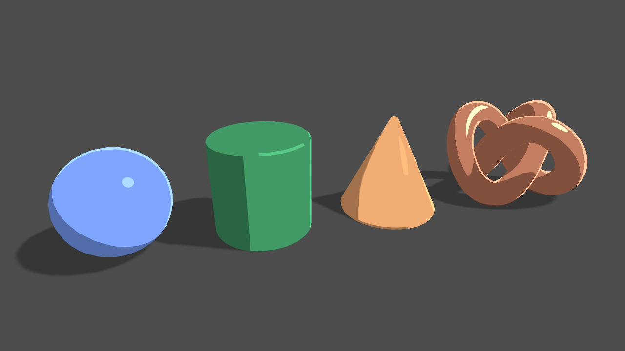
Learn to write a toon shader for Unity engine with specular reflections, rim lighting and shadow casting.
Here
OMG
YOU ARE AMAZING
i have BEEN STRUGGLED FOR MONTHES
I DONT KNOW HOW I THANK YOU
HUH MAI GUDH
It was just one simple google search away but okay, you're welcome
Yes, you can do it a few ways. There's a colormask property that you can mask off all color-buffer writes. Or there's another way. See article here:
https://www.ronja-tutorials.com/post/022-stencil-buffers/
He uses built-in pipeline, and you didn't specify, so IDK if this will help you or not. But he wrote
ZWrite Off```
I'd check the colormask functionality though.
https://docs.unity3d.com/Manual/SL-ColorMask.html
They even say **"Another common use case is to disable color writes completely so that you can populate one buffer with data without writing to others; for example, you might want to populate the stencil buffer without writing to the render target."** Although the documentation is confusing...I think the ```ColorMask 0``` DISables color writes, IIRC, not enables them all as the docs currently read.Summary The depth buffer helps us compare depths of objects to ensure they occlude each other properly. But theres also a part of the stencil buffer reserved for “stencil operations”. This part of the depth buffer is commonly referred to as stencil buffer. Stencil buffers are mostly used to only render parts of objects while discarding others.
T...
When you use the position node, select object-space position. It will do that for you. It actually comes in as local space and gets transformed to world space (eventually). So it will just "keep" the local position if you use it in the graph. If I understand your question. There should be no need to go back to the start again.
But if you're passing it in, like from C#
I don't use the position node.
You can do an inverse multiply. There's a matrix for world-to-object transformation, but you might have to pass that in too.
to clarify: by input I meant parameter, not like an input node.
Like I was saying, you'll have to pass in the world-to-object matrix.
why would I need to do inverse multiply? I'm passing a world position from outside, transform from world -> object is what I want, and it's on the dropdown?
or am I confusing something here?
It's the reverse of the usual operation.
You can't get object position for an arbitrary worldspace point, because there's an infinite set of possibilities, UNLESS you have the world-to-object matrix.
isn't that the responsibility of the transform node?
that is what I was expecting it to do; get the world position, and transform it to object position by using the world-to-object matrix. (without me passing it manually)
IDK what you're doing. If the world-space point is for a known object with a transform, then it will know how to go back to worldspace like you just said. But if it is just some arbitrary WS point, it won't know what object.
Assuming it is the object it is processing.
If it is some other object, it won't have the matrix.
what? what are you talking about?
world space is absolute, there's no issue with that - the space doesn't matter.
for an object O, if I want to transform a position from world to it's relative space (object space) - it would have that data.
Object space isn't absolute!
that is, "world-space point is for a known object" - that doesn't make sense. world-space is for the world, not for an object.
I know, world space is!
Communication is hard.
WS is absolute. OS isn't.
But if you know the Object, you can use the world-to-object matrix.
exactly, I agree on that.
Which is where we started.
but the shader graph already as that matrix; it has to.
Then use it.
I don't have it, it does.
I thought that is what the Transform node can be used for.
it knows the object (self). I'm giving it the world position.
Hence it knows to use the world-to-object matrix (which it must have).
What else does it need?
What is the question? That is what it is for.
There's a "from" and an "to".
Go from WS to OS.
Does that not work?
nope, it doesn't.
Position is similar. Depends on what you were doing, I assumed a vert.
what? no idea what you just said.
Maybe it is a different bug? Can you post a graph?
Kinda complex since I have lots of tests in it, but this is the important part, that's connected to alpha. Notes:
- I use distance to (0,0) so I can visualize it on the scene, and see it works.
- I used the division to try and find the position where it's currently at.

Did you try world rather than absolute-world?
lol
See the sample code for the function here:
the world one is using the world-to-object matrix that you want.
That's an older link but ...
seems like the absoluteworld-to-object does the exact same thing btw
@meager pelican btw, I should note I found a solution eventually, in the meantime xd
I'm still interested to know why this doesn't work though.
The solution, if you're interested, was to do the opposite.
Instead of transforming my world position to object, I used world space for everything, and for object position I used the Position node
You're right it does do the same.
We're going in circles.
just seems like the Transform node doesn't do what it should 🤷♂️
You can do that, but you then don't need to do those transforms at all since you're sending in worldspace already. BUT...you have to have a way to go to clip-space to output from the vert().
you have to have a way to go to clip-space to output from the vert().
Don't know what it means, but it's untrue anyway xd unless by "you have to" you mean "unity will provide for you" xd
It may generate it yeah. The vert() stage outputs clip-space. It HAS TO it's part of the hardware. Then the rasterization happens along with a perspective divide.
@meager pelican I do have another question that I can't seem to work for quite some time though, if you're familiar with the area:
Any chance you know how to get scene color in a post processing shader in 2d renderer urp?
I don't do much 2D, but last I knew scene-color node didn't work in 2D IIRC, so you'll beat your head against the wall for hours trying to figure out why it isn't working! (Been there). But maybe there's updates depending on version. That's all grain-of-salt.
Cyan may have something or know more.
BUT...there's probably a work-around. Since you're doing post-processing, you may be able to "cheat" by doing your own render pass for it. In that case, you're not really doing a "scene color" node, you're just reading the back-buffer. The camera has to have a back buffer. I think that there ARE post-procesing examples for SG/URP, so I'd start there and abandon the scene-color node approach, which is a red-herring?
All, again, grain of salt.
@meager pelican based on your own thoughts/experience - how long would you expect Unity to support it?
I'm asking because I need it for my final version of the game, and it's going to take some time anyway; so might be worth to just wait for it.
IDK, and you're kind of saying two different things in your question.
Because scene-color node isn't post-processing.
Scene-color happens between the opaque and the transparent passes.
Post processing is after the transparent pass. So to the engine, they're different steps. Which is why I was telling you to "think post processing, not scene color".
also,
Cyan may have something or know more.
Who is Cyan (multiple users with that name come up when trying to mention)? can I mention him to ask him?
mm I'm not familiar with the opaque / transparent passes, although it's possible that is what I tried since Unity doesn't really expose those passes in the Editor.
but from what I know about post processing, I was referring to what you were referring I should do; read the back buffer.
That is, it's another pass after the scene has been renderered.
The dependencies are on what you're trying to do....
For example, if you want a heat-distortion effect for semi-transparent "smoke and heat"...you'd do that in the transparent pass and maybe blend it in. THEN you want the scene-color node in a transparent pass for the area/object that you're shading. (Which last I knew didn't work well in 2D).
But if you want to basically process the "whole screen" and do a pass over it, that's post processing.
For example, if you want a heat-distortion effect for semi-transparent "smoke and heat"...you'd do that in the transparent pass and maybe blend it in
Why? or rather, isn't it also possible to do that in a post processing effect?