#archived-shaders
1 messages · Page 209 of 1
Though from that I've discovered that the texel size is wrong
it should be .333 but is only .3
It doesn't explain the issue I'm having but it's something
No, the filtering is set on the sampler.
The code is where/what to sample, and that is where you were having a problem.
One is the software, the other is the hardware-settings on the sampler hardware.
But I'm glad you found the inaccuracy in your inputs. 🙂
Oh thank god I finally found what was going wrong
Anyone have any opinions on my shader fixes? Been struggling now for a bit.
Apparently textures do automatic color space conversions unless you specify not to
It had nothing to do with that line of code, just my lack of knowledge about textures
Well, it is true you have to have the right data in the texture to begin with....
Glad you got it sorted out.


looks like perlin noise
Is it right that y have to script your own "material instance" as a shader. Unity does not have a prebuild-shader to handle that?
I need a "material instance" to be able to change appearence of different objects while only rendering the given material once.
Most vfx artists I know keep their own libraries of repeating patterns to use for effects
You could make them in photoshop, gimp or any program really
Substance designer has tools to generate just this kind of patterns procedurally and they're repeating too, but the cost is steep
The free alternative Material Maker might be able to do that kind of stuff too, though probably not as well
So might Quixel Mixer and Armor Paint, even if they're more geared for mesh painting
Noise patterns for effects don't have to look perfect by any means if you use them convincingly
You could take photos of random surfaces, make them repeating by fading the edges and apply some contrast and filters
Its far from it. 😢
its amazing and it looks good
Nah I need to get an outline shader, and a better toon shader still.
The outline shader is well... stupidly complex for a good one.
Toon ones are easy enough to come by for the most part.
Why I can't plug in?

You can only use texture sampler nodes in fragment shaders, not vertex shaders.
Hmmm I see
You can use the Sample Texture 2D LOD node in the vertex stage
I’ll look into it
But here is the youtube video,It can plug in

This image doesn't show a texture sampler connecting to a vertex shader, as far as I can see.
If you're referring to the normal input, that's the fragment "Normal (Tangent Space)" one, not the Vertex Normal.

Sorry,I still didnt understand

I tried the texture lod and it did work,But why sample texture doesnt work?

Maybe this is the old version?

Hello hello, in this video we're taking a look at crystals in Unity. They're real easy to make look great, and slightly less easy to make look awesome. Hope you enjoy, and don't forget to grab the download on my sketchfab if you wanted to use it for literally anything.
Peace be with you my dudes.
♥ Subscribe For More: https://tinyurl.com/y7hdj...
this is the video,at 5:15 I took the screen shot

Maybe u need to upgrade them,I just guess
how ??
Edit-renderpipline-... U will find the option
I do not find
Edit-RenderPipline-Universal Render Pipline-upgrade
yes but where?
The "Normal" port on that PBR node is the fragment version, not vertex normal. Labelled a "Normal (Tangent Space)" in the newer versions.
I swear shaders are like...
The devil.
Maybe I should stick with pixel art :^)
U need to install the package for render pipline
i cant do pixel art so im trynna fake it with shaders lol
You gotta code the pixel-perfect outline shader for us first 😏
Ohhh,thx,I c
Create outline shaders for Unity that have a stable screen-space width, specified in pixels, regardless of distance from the camera.

where do I install it
thank
"Similar" effects seems right
There's so much that seems rather hard if not impossible to achieve with plain SG
I mean, at the end of the day, it's not that much different from my understanding.
One is node based, the other is code based.
i see
But overall, it's basically just a Toon Shader with a Vertex Outline on it. From there it's a "Pixelate" effect on the camera.
I'm also new to shaders, but just googling "Toon Shader with Outline" should lead you in the right direction. or "Pixelate the camera"
The effect is very simple, just color-limited light and pixelated screen
Real difficulty is figuring out where and how the hell to do those
I lost a chunk of my braincells when I discovered that SG can't access lighting information
At least not without a subgraph that unity themselves supply
on their blog

Like I just spent most of my afternoon implementing this

because if it is h o w
it looks good though
Nah. It's pretty bad TBH.
Watch more of that guy's videos, especially older ones so you see how the effect shapes up


i only have blender experience so it doesn't look to bad to me
ok
Compared to t3ssel8r's shaders, it's pretty crazy.
if i can master that look
game dev for my project will be way easier
instead of p i x el
a r t


your game isn't going to magically look good by putting a shader over it, you still need to consider colors, materials, textures, models, etc
its not going to be that much easier than learning pixel art
Procedural pixel art is harder than manual
You need to understand why it looks good and then recreate that look in an entirely different context
Though who cares about that anyway these days
Slap some stretching textures without filtering and it's "PS2 style" now
Hue.
Though you're not wrong.
I got a few reasons for wanting to go the 3D Pixel Route, and it's mostly due to most of the artists I'm working with are more familiar with 3D models. That and being able to rotate the camera/rotate objects is fairly hot.
Personally, I'd prefer it if my shader looked more like this vs the t3ssel8r stuff. (This being the header image)
https://www.videopoetics.com/tutorials/pixel-perfect-outline-shaders-unity/
However, again, completely new to Shaders and not sure how to achieve that look.
Create outline shaders for Unity that have a stable screen-space width, specified in pixels, regardless of distance from the camera.
i am aware but using shaders and nodes is easier for me
Is HDRP distortion really only available for Unlit shaders? You can't enable it any more on a Lit shader like in this video? https://www.youtube.com/watch?v=XTnobfLSTV0

Let's make a photo realistic glass material in Unity's High Definition Render Pipeline (HDRP).
✅Unity Office demo Project:
https://github.com/Unity-Technologies/SmallOfficeRayTracing
▬▬▬▬▬▬▬▬▬▬▬▬▬▬▬▬▬▬▬▬
💎 Watch advanced tutorial on Patreon 💎
http://patreon.com/uguruz/
▬▬▬▬▬▬▬▬▬▬▬▬▬▬▬▬▬▬▬▬
📱Social Links:📱
🔸 Discord https://discord.g...
I'm trying to create a saber trail effect but I can't figure out how to do the material. Basically I'm creating two triangles along the path of the saber, but I want to make a texture that starts out bright near the saber top and fades to transparent along the way, but I'm not sure how to accomplish this. Any ideas?

I'm not sure how that would work because its not an animation type system, its vr real time following a saber
Still should work? Just attach it tot he saber?
I dont know how I would make that particle is what I mean
Seems like you would need to make a mesh just how I'm doing above

https://docs.unity3d.com/Manual/class-TrailRenderer.html
Might be a good place to start.
LOL
TrailRender >Line Renderer probably in this case.
Ill check those out
@vague yacht It was moved to the forums, links here #854851968446365696
Thanks! I'll make a post there too, but I've noticed that it's kinda empty - plenty of job offerings but almost all of them have 0 responses. Unity Connect had a chat with e-mail notifications 😦
@vague yacht You should read forum rules This forum is not a place for discussions. Commenting on threads is disabled except for the thread starters.
@vague yacht Should read #📖┃code-of-conduct as well. There are no reaction gifs allowed here.
I think I've given up with Shaders 🙂
I mean on the topic of 3D Models to Pixel Art shaders.
Dead Cells is also a 3D Model for their character.

Get the Shaders for this Video here ➜ https://github.com/Broxxar/PixelArtPipeline
Support me on Patreon ➜ https://www.patreon.com/DanMoran
Follow me on the Twittersphere ➜ https://twitter.com/DanielJMoran
Extra Links
Gamasutra article on Dead Cells' art ➜ https://www.gamasutra.com/view/news/313026/Art_Design_Deep_Dive_Using_a_3D_pipeline_for_2D...
But I wouldn't recommend it.
Hey everyone is there a way to control mesh rendering order, since I have clothes a jacket and a T shirt I want the jacket to render over the tshirt is that possible ?
for a metallic/occulusion/smoothness map, are there standard channels for each parameter to be in?


How to turn the shard of back into invisible?

Aren't Vector1s just floats
So maybe you'd do like
mat.SetFloat("_OutlineThickness", thickness);
In v10, Vector1 was renamed to Float. The extra settings also moved to the Node Settings tab of the Graph Inspector window (when property is selected)
Does anybody know if there was ever a work around for render texture transparency on URP when using post processing? I'm on 2019.4.19f1
Currently it completely ignores the camera clearing and won't allow transparency unless PP is turned off repost from render pipelines
(shadergraph and URP) I made a shader using transparency and while it renders fine in the editor viewport the game view appears flat? I found that enabling screen space ambient occlusion in the forward renderer fixes this though the occlusion renders in front of the material making for a strange effect

Yeah I looked into that, not the best of options really.
Is it possible to do a edge shader without post processing? It seems most are related to post processing...
you can do outlines without post processing
Less about Outlines. I'm looking to do edge highlighting.
Most shaders I've seen are just your standard toon outline.
Good example.

If the shader makes use of the Scene Depth node, make sure the Depth Texture is enabled on the URP Asset. Might also need Post Processing ticked on the camera
This is probably done with post processing still, but edge detection can still be done with regular shaders too, it's the same process. It involves comparing neighbouring pixels' depth and normals so you'd need pre-passes to render those to textures you can sample multiple times. https://alexanderameye.github.io/notes/edge-detection-outlines/ is a good example to look into for URP.
Yeah I was just reading that.
I could be wrong, but this also seems to be applied to all objects.
The example is an image effect so is applied to the whole screen yeah. It used to have a per-object version, I guess it's being rewritten as Alexander recently updated the site to a new design. But instead of using the second "blit" render feature, you could apply the material to an object in the scene and swap the UV node out for the Screen Position node.
(Though now that I think about it, might also have problems with using URP's provided depth texture if not using MSAA as it copies after rendering opaques instead of doing a prepass then, so the CameraDepthTexture would be from the previous frame)
Yeah Im not sure, I even downloaded the Chop Chop (Unity's Toon Shading) project and they don't have character outlines anymore.
So, i have this code: cs public void bombThrow(GameObject thrower, Tilemap destroyMap, Vector2Int radius){ for(int x = -(int)radius.x; x < radius.x; x++){ for(int y = -(int)radius.y; y < radius.y; y++){ Vector3Int tilePos = destroyMap.WorldToCell(gameObject.transform.position + new Vector3(x,y,0)); if(destroyMap.GetTile(tilePos) != null){ destroyMap.SetTile(tilePos, null); } } } } (called from another script) which lags my game a bit, so would like to use this to learn how to transfer stuff to compute shaders. Can anyone tell me how i would do this?
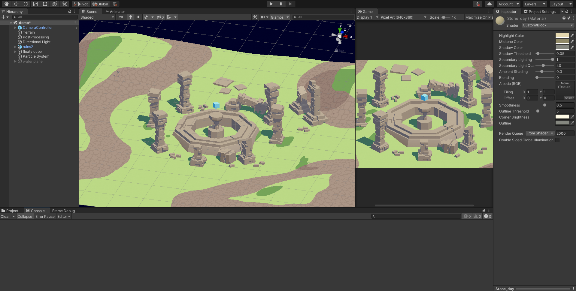
hi folks im trying to create a shader where i can control the color of the highlights, midtone, and shadow colors. any help would be great.
just wondering if anyone can point me the rightway?
sorry for ms paint but basically i want to do this

pick the three colors of a cube i guess using a shader
basically i want to set these three colors by hand...

should be pretty simple, no? Just determine the brightness of the fragment in a normal PBR way, then just check if it's in one of three brightness buckets and output the desired color for each bucket
maybe? im new to shaders and im just basing it off a reference image. i thought i had something working, but i cant get it to match at all.
I wrote a shader to colorize (base color) parts of character body when some objects are in front of him.
It is OK but I would like to add some exceptions to it like his weapons. It should not cause that part of character becomes for example white
One way is to render weapons using another camera but it is not perfect
Should I use stencil for that?
Can't you use two shaders for that? @toxic flume
don't access gameObject.transform.position inside the loop
do a var pos = transform.position;
this doesn't look particularly straight forward to move to a compute shader
you might have an easier job turning it into a Job
but both will require significant changes to structure
and how you are storing the data
would u have the time / effort available to sorta coach me through it?
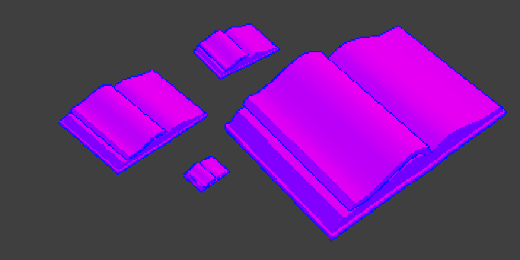
This looks like a recolor of
lol
Oh that didn't link the album.
Which to be fair I'm curious of the shader he's using here: https://i.imgur.com/FFaW9Mx.png
Also make that 6 now. Lol
so i just made this in blender

and i wanna put it into unity
and i used alot of shaders and things like that in blender
but when i transfer it over
its just texture less
Textures/materials aren't packed with an FBX.
You have to recreate the look in Unity.
Is it possible to change the default shader/material for Unity Terrain? I want to be able to generate many terrains that default to a specific material without having to manually change them.

Yes I'm aware of that option on the terrain component but I'm looking for a way to change the default material for all new terrains. I can change materials on a terrain that I've already created but making a new terrain results in it defaulting back to "Default - Terrain"
I'm procedurally creating many terrains and need their materials to be using my custom material/shader when they are created.
would it be this then? https://docs.unity3d.com/ScriptReference/Terrain-materialTemplate.html
What do you mean exactly? could you explain more?
See the weapon sniper. I do not want to colorize it. Player's weapons are exception and should be rendered normally regardless of behind or front

 SubShader{
        LOD 200
        Tags{
            "RenderType" = "Opaque"
            "Queue" = "Geometry+1"
        }
        Pass {
            Name "Silhouette"
            Cull Back
            ZWrite Off
            ZTest Always
            ColorMask RGB
            CGPROGRAM
            #pragma vertex vert
            #pragma fragment frag
            uniform fixed4 _SilhouetteColor;
            float4 vert(float4 vertex : POSITION) : SV_POSITION{
                return UnityObjectToClipPos(vertex);
            }
            fixed4 frag(void) : SV_Target {
                return _SilhouetteColor;
            }
            ENDCG
        }
            Name "BASE"
            Cull Back
            ZWrite On
            ZTest LEqual
            CGPROGRAM
                #pragma surface surf StandardSpecular fullforwardshadows
                #pragma target 3.0
                struct Input {
                    float2 uv_MainTex;
                };
                half _Glossiness;fixed3  _SpecularColor, _EmissionColor;fixed4 _Color;
                sampler2D _MainTex;
                void surf(Input IN, inout SurfaceOutputStandardSpecular o) {
                    fixed4 c = tex2D(_MainTex, IN.uv_MainTex) * _Color;
                    o.Albedo = c.rgb;
                    o.Specular = _SpecularColor;
                    o.Smoothness = _Glossiness;
                    o.Alpha = c.a;
                    o.Emission = _EmissionColor;
                }
            ENDCG
then just make a shader with the bottom half and ZTest Always
What? bottom half
the base shader, which has color, etc
can I somehow detect from script if a Fallback on a certain shader/material has been hit. I want to disable a renderer feature in URP if the shader goes to its fallback
@vocal narwhal 😐
I'm happy to answer specific questions
the #archived-dots channel would be more appropriate
ok thanks! also i tried decreasing the size of the destruction to just 1 block so i think its getting backed up at changing the tilemap
I'm not sure how you are representing things, but your tiles should probably not be full game objects if there are a lot of them
and you need to create/destroy lots of them
they are on a tilemap
ah ok
Kind of dumb question, but I'm working on a fresnel flicker effect for damaged gameplay elements. It works on a timer and flickers every so often based on how damaged it is. Would the timer be better written in the shader graph instead of C#?
Wonder if the GPU or CPU is more efficient for timers, I'm not sure if my performance is GPU or CPU bound at this point
it's probably so negligible on the grand scheme of things but I'd still be interested in perspectives
Is it possible to convert C# arrays to compute buffers?
I do that stuff in C# for some reason, and just "pass" this is-flickering, or the amount-of-flicker-intensity or whatever to the shader. Same way you set a primary color on a material. I mean, it's just numbers, you COULD do it in the shader, but why? Give C# the control, and then you don't need a shader programmer after it's initially done. But that's me.
It's in shader graph for me, which I think most people can pick up. You're right though, C# is much more accessible generally speaking... timers are some of the easiest things to learn
But if there was a performance benefit to doing it in the shader, I'd consider it. It's probably too minor to matter
You're going to have to set something either way, and maybe change it for varying rates, it's harder to keep track of things between frames in a shader, you'd have to have temporary storage (like texture data or a compute buffer) to track state changes like on, off, intensity, and it's just a lot more complicated if you're not doing it already for something else, so I'd leave all that to the object on the CPU side. 🙂
So maybe you can do it based on time and some kind of rate variable, like a sign wave, and then positive is on, and negative is off, and all x rate, and then just a bool for is flickering or not.
But otherwise, if more involved, you have to track it.
It's really up to you, there's no one way.
is there a way to create 2d distortione effects?
@long lynx https://www.youtube.com/watch?v=CXCyVDEplyM
he uses a 2d plane, so the procedure should be similar

Let's see how to create a Heat Distortion effect in HDRP and URP. Also known has heat haze or air distortion is a visual effect used many times in games to convey the feeling of something so hot that it distorts the air around it or to create a mirage.
00:00 Intro
00:38 HDRP - Screen Space
05:12 HDRP - Normal Based
06:32 URP
15:34 End Credits
...
This is for HDRP or URP
But I'm sure it's also similar in Built-In
Hello! I've tried using the new Shader Graph thingy to create a 2D outline shader, because adding outlines to each texture I want to use is kinda hard.. 😅
I saw multiple tutorials on youtube from people like Brackeys and Code Monkey:
https://www.youtube.com/watch?v=MqpyXhBIRSw
https://www.youtube.com/watch?v=FvQFhkS90nI
However, in their shader graph structure they substract the alphas to find the differences between the original and the shifted textures:

The problem is, I want to outline a black rectangle, so subtracting the alphas just gives me nothing..
Is there any other way to do an outline though? 😅
The alpha and the color are separate channels. You can have a black rectangle with alphas values of what you want. Just say'n. But you're probably trying to import alpha for a texture that doesn't have them? Or what do you mean by "want to outline a black triangle"? What you're showing is a sprite sheet.
Well, I tried to outline this image by shifting it to the left (by .005) and subtracting the alphas of both textures..

Try alpha from grayscale on the import.
I assume you want to outline the O the M and the G.
well.. my initial thought is that i could place an empty black UI image, and add something like a white outline to it like here:

but in this screenshot it's actually an already outlined texture.
So you want a white border around your texture REGARDLESS of alpha.
And the whole texture's square.
yeah
UV values for a texture range from 0,0 in the lower left corner to 1,1 in the upper right. Now, you'll have aspect ratio problems, because it's not a perfectly square texture, so the length of the sides is shorter than the length of the top and bottom in this example. So you'll have to adjust for that in the math.
BUT
You can decide in your shader to "show white" if the x or y values are in a certain range that would be your border area.
Or what's probably easiest is to use that pic you just posted (but maybe perfect square) and pass that in too, and just overlay it where it isn't black. 😉 A cheat.
Then you could add your border texture to whatever your other texture is, and then do a saturate to clamp it to 0-1
You can decide in your shader to "show white" if the x or y values are in a certain range that would be your border area.
oh wait there are two types of outlines, right?
the inner and the outer..
Hi ! I want to know if Amplify Shader is compatible on Linux plateforme
if the build is compatible on consoles (switch, xbox etc)
and if a demo of Amplify exist , I want to see what he's capable of before buying
Yeah, it's kind of like belly buttons.
So, what type of outline do you want?
probably the outer
I knew you were going to say that.
That makes it more complicated.
One way is to oversize it in a 2nd pass and draw the rectangle border were it doesn't intersect the first pass. But oy. IDK.
😅
I'd have to mess with it if you want a rectangular texture outline. Maybe @devout quarry will comment or have something on his site (he does outlines quite a bit). He has this that might give you some ideas
https://alexanderameye.github.io/notes/edge-detection-outlines/
but I'm not sure it fits your use case.

Drawing outlines as a post-processing effect in Unity.
Others may pipe in too. Good luck. 🙂
In a script, Shader.SetGlobalFloat(string, float) should be in which fonction?
How to make it change even in inspector but without loosing performence?
I have a ramp texture currently setup for my shader, however I'm looking at instead, doing it via sliders/colors.
Anyone have any resources to point me in the right direction for this?
I know I could use the Gradient Node, but yeah.
What does "sliders/colors" mean exactly. I can interpret that a few ways....
I mean you might just be asking about a lerp...
lerp(color1, color2, t) where t is a float from 0 to 1.
Sometimes my farts have a brain.... 😉
TBH would be just easier if Unity exposed the Gradient.
But for some reason they be dum like that.
Im basically trying to recreate this, but, with three color inputs instead.
@upbeat heart I’m not 100% sure what you need but as @meager pelican said, for an outline you can 1. Create stencil mask based on original texture 2. Draw rectangle second time, scaled up, and discard using stencil mask
Another option is to do 1 pass where you draw all of the textures with a solid colour to a buffer so you get their silhouette, then you do a blur pass to expand it and use it to add an outline to the original textures. However, if these are just 2D textures, I would re-draw them scaled up, in a solid colour, like in my previous message because that’s cheaper than a blur pass.
@grand jolt A ‘good’ way to do this is to have a customer material editor for you shader that exposes a gradient field, then you convert that gradient to a texture that has a size of like 512x1px and you sample it in the shader. This technique is used a lot.
Yeah I thought about that as well. I ended up thinking more like a Programmer.
If Value is between Threshold, make it one color, else, make it another color.
This might be of use as well I think, lerp function between 3 values

This is from @amber saffron
That one's 3 color, so it's a bit more complicated.
Yeah, I like, in my case, lerping isn't exactly what I was looking for. Was more steps. (Toon shader)
Though maybe doing the step isn't what I'm looking for. Blah.
If you're doing that, with variable levels and MULTIPLE sliders, you need to either use the gradient node and plug in the array values (you can get them from the gradient control in the editor, the array is exposed/returned) or you can do what A.A. mentioned and convert it to a texture for an easy lookup (it's just a texture sampler with a x value on the UV of the "t" part) and let it interpolate, that's what a GPU is designed to do with textures. I'm not even sure why you'd need a custom editor, but you can if you want. The normal color gradient in the editor is fine, and you can use a script somewhere to convert it to the texture and update it with setPixels in a loop for the texture size while calling Gradient.evaluate.
https://docs.unity3d.com/ScriptReference/Gradient.html

🙂
The only issue I'm currently hitting is that if I decide I want to do a smooth gradient.
Where I should be plugging that into.
That isn't how it is written, it's a boolean result of a compare (greater). So it is, or it isn't.
If you want a gradient, you don't want a hard-bool decision, you want math.
Looks like the one A.A. posted from Remy will work for that though.
Right, fully get that. Hmm.
Also need to fix my shadows still.
Right now, They cast shadows, but they don't recieve them.
Are you using a LIT shader?
But that has complications too.
Because of other calcs.
Unlit, I was following the Ned Makes Game's Tutorial.
If not, it's starting to get a lot more complex than you probably realized it would. There's no node for "receive my shadows", and unlit shaders don't receive shadows (I don't think).
So......
You'll have to google "Unity shader graph receive shadows unlit" and have fun.
🙃
I've seen some stuff for attempting to recreate Legend of Zelda BOTW, for example, but it's not a few nodes....
IIRC, or it was something else, but toon like shading.
You MIGHT just try "simple lit" and screw with the base color, but I think you'll get shading gradients in it. Would make sense, since some lighting calcs are per original pixel from the get go. Others are added on later, like the shadows.
That's why they started with unlit, then you get what you set.
I don't know if this is the right place to talk about this, but how does a cube in Unity have 24 verticies when it actually has 8? That makes no sense!
What's 3x8?
😉
The reason is that each "square" duplicates verts with its neighbors in the same location.
You CAN make a cube with 8 verts though, like in blender.
Or programmatically.
The reason they do that is so that it has flat surface normals on the cube, because normals are stored per-vertex.
That also allows you to have per-plane vertex colors. Like the top being white, and the right side being blue, and you have enough verts to store the color and normal data into.
And 3 planes meet at each vert. So 8x3. 🙂
Does anyone know why there's a seam in the water? It's noticeable in the specular reflection

Here's the uvs in the same place, 99% sure that the seam is on the edge of the uvs

But I'm also pretty sure that the texture is supposed to be seamless, so I didn't think this would matter very much
also I assure you it's much more noticeable in game when moving about, I'm not being super picky lmao
If the texture is seamless, that's not likely it unless it has a defect. So then I'd start looking at calcs....that pic seems to have the highlights spread across the screen in an...interesting...way. And maybe you're using vertex displacement?
So all in all, I'd first wonder about floating point calcs messing with you and make sure you're not using something like half or worse fixed, and I'd check the offset calcs for displacement too.
But I'm totally guessing.
So, I got it working, but it seems that I need to add: "MAIN_LIGHT_CALCULATE_SHADOWS _MAIN_LIGHT_SHADOWS_CASCADE _SHADOWS_SOFT" to every material I make, which seems annoying?
there's 0 displacement but I'll check
How did you go from a flat plane to hills?
nope no fixed or halfs or any of that crap
I'm just talking about the water
Probably. 😉 It needs that to know what to do in what passes. Maybe someone knows of a better way.
Yeah if anyone knows an easier way, that'd be great.
I can probably just write a function that makes it so the uvs don't go from 1 to 0, and instead they just go up and down etc
Yeah, IDK. Maybe someone else will chime in, it looks like there's a "water" ghost over the whole screen, and then it looks like the water is clear except for specular, and then purple mountains (Magesty? lol). So if you turn off the water, is there still a "seam"?? Because maybe it a calc artifact of the specular.
no when the texture is off the specular is totally fine
it's far to suspect that the seam fell right where the uv's have a seam, that's no coincidence
Is that water clear except for the specular highlights? Maybe tint the water, and see what that seam is...
yeah the water's there I just had it very transparent lmao
but yeah I did some more testing and it's definitely the uvs
Huh. It's one mesh, yes?
Are you vert displacing the water for waves?
If so, sometimes if the mesh is messed up somehow, you'll get seams. But that's a mesh-issue then. You could check that you're sharing verts in the mesh and NOT duplicating them.
Then all the polygons only have one vert that they share per corner/side.
no the mesh is in chunks
so lots of meshes
no displacing
the seam isn't on the mesh seam
the seam is literally wherever the uvs are
because I have the uvs moving along to simulate water movement
We have a terminology problem I think, or I'm not understanding you.
UV's are just % of the way through the polygon's mapping. Of course, they're mapped in the mesh editor.
But you shouldn't get a seam. Prove it's a seam. Seams are for meshes. IDK how a mesh maps to a UV. I only know how UV's map to meshes.
(well verts).
well lets say we have a plane (4 verts, just a square)
Output a color for the water, no calcs. Like blue.
you can have the bottom left uv be 0,0
See if the seam is still there.
then top right be 1,1
but you can also move those uv coords along
so wherever the uvs go form 1 to 0 is where the 'seam' is
Yeah, but it's the verts that determine where the polygon is rasterized to.
Not the UV
the polygon doesn't matter though
It does if you have seams!
well we won't use the word seams then
we'll use whatever stands for, the part where your texture tiles
or where the uvs go from 1 to 0
OK, then we're talking about texturing, not seams. But...OK...so UV's should wrap smoothly, AFAIK. This isn't mobile is it?
Anyway, should work. GPU's have been wrapping UV's around and tiling since forever.
yeah so I'll just make a function maps the uvs smoothly instead of a sudden 1 => 0
So are you trying to reset UV's? Why? Just let them wrap. The GPU knows what to do.
if the uv coord goes to high it fucks stuff up
IDK, I can't see the shader.
But you can tile/offset too.
What pipeline? What type of shader? Desktop GPU?
I mean it'll be fine, I'll just make the function, I prefer making my own methods anyways
was just useful to pinpoint the problem
thanks man
Have fun, but you're probably calcing more than you need to....
🙂
And check that your texture mode is set to wrap, just to be sure.
Yeahhh... Shadows are going to be annoying. :^)
Its actually weird. I have two Toon shaders I made.
one uses a ramp texture, the other uses colors.
The ramp texture one seems to work correctly.
Yeah, that's the texture method. So fine. You're probably sampling another texture anyway, so the two samplers can run parallel at the same time. You MAY end up with the same "hit" either way, since you'd have to have at least one sample for albedo.
Like, this is roughly what I'd expect.
White being the Highlight, Blue being the midtone, Green being the shadow.

But even tweaking the values by just a little bit, I can end up with some weird results.

Sounds like the math or something.
But if the texture-sample way works, why not use it? Are you sampling another texture anyway?
If you can avoid texture sampling altogether, that's one thing. But if you have to sample one, you can sample two for pretty much the same relative cost, IIUC.
It's not 2x cost compared to just one.
It's more so that I'd like to be able to change the ramping values whenever I'd like. to be able to just change it on the fly.
You still can, it doesn't take much to update that type of texture. But, hey, there's 50 ways to do things. It's all good as long as you get it working. 😉 🙂
how am i supposed to do this? The way im doing this rn seem to complicated

here is my texture

and camera

im having to rotate my camera to see from the monitor
thank you so much! i decided for now that i'll just outline the textures myself, since i probably won't need it later and i've already had a lot of pain 🥲
got the left from kitbashing the right with another model,
however it seems i cant get the left to follow the right's glossiness.
i've been trying to get it so each setting is exactly the same and it still doesnt work.
am i missing something???

all i currently have on is emissions so theyre both not completely white
could somone please help i have a texture2D (it is a plain white circle with 0 alpha around it) that goes into the texture of my sample texture 2D and it outputs this weird image

You should post your graph, this isnt terribly helpful
i just described it
that is litterally the only thing
but ok

there
like i said
literally the only input to that node
I think this sort of thing is common for textures with 0 alpha. As long as you use the alpha channel it won't be visible anyway.
okay
kind of something I wanted to revist it since I havent really found a way yet. I was hoping to make the texture be able to do the darken layer effect similar to photoshop


but the effect is similar but not as close as I think it should be
Connecting the Alpha like that isn't correct. Connecting a Vector4 to a Vector1 port will just take the first (red) channel. Instead you might want to Split to take the A channel, though perhaps you don't want to blend the alpha at all and just use the A output from the MainTex.
Probably also need to connect the MainTex A to the Opacity on the Blend node.
You might also need to swap the textures, not sure.
You could just multiply the specular part by a scalar value less than one. Maybe make that a slider. Just off the top of my head. Call it specular intensity, maybe.
oh ok thank you let me try that
im not sure if this is the correct place to put the split

it results in this tho

Does not look right to me
haha very true
with this being what im aiming for

I cant hardly tell what you are trying to achieve there, the dropshadow or what exactly?
the way the purple kind of takes over the other colors, the darken layer effect
I got this weird issue currently where my colors don't appear to be gettign applied?

Wait. I mgiht be stupid. Usuaully I am
Right, follow up question because its driving me insane.
How do I set Shader Keywords as a default value?
Every time I create a new shader I need to add this and its sort of driving me bonkers.
You can change the default values of Unity in general, if thats what you mean
Can I do it per shader?
I'd recommend switching to using the subgraphs here for lighting : https://github.com/Cyanilux/URP_ShaderGraphCustomLighting
Won't need to set keywords manually, and the method you're using currently might not work in builds anyway.
Currently using a Subgraph for lighting, but I'll look at this.
Am I missing something obvious here? I still need to go into the debug and add them.

Hello
Is there a way to map a collision position in a shader
What I mean is, if two objects collide, a cube and a sphere, would it be possible to map that collision so that let's say you can make a collision effect in the shader ?
TMP shaders: how to change Underlay to Additive and Glow to Multiply?
Should use the _MAIN_LIGHT_SHADOWS keyword instead of MAIN_LIGHT_CALCULATE_SHADOWS.
With that URP should handle the keywords automatically (and it's required to stop the other shadow keywords being stripped from the build). The problem is with an unlit graph it can produce an error with No/1 Cascade level, so to prevent that I use #undef REQUIRES_VERTEX_SHADOW_COORD_INTERPOLATOR in the custom function include file.
That did it. Thanks!
One more question for the day: https://alexanderameye.github.io/notes/edge-detection-outlines/
I tried to implement this finally, double checked and I followed the tutorial fully. However, no luck getting an outline, and no errors either. Just wondering if anyone else has had any luck regarding this.
Drawing outlines as a post-processing effect in Unity.
Nvm. I was just... really stupid.
🙂
OH, you're talking about GI baked/realtime lighting. Yeah, that's different than self-lighting. Its a different pass. But you're in shader graph, not built-in. There are custom lighting tutorials for SG but you basically do unlit and then roll all your own lighting.
The thing is that the Lit material (I'm talking on V 10 so maybe they have a simple-lit now) is PBR, and you seem to want your own lighting calcs, so you have to roll them yourself in an unlit graph. You CAN use a specular workflow however, the glossiness is the intensity of the reflection if that helps any. Otherwise, you're off to the races.
https://blog.unity.com/technology/custom-lighting-in-shader-graph-expanding-your-graphs-in-2019
https://github.com/Cyanilux/URP_ShaderGraphCustomLighting


GitHub
Some custom lighting functions/sub-graphs for Shader Graph, Universal Render Pipeline - Cyanilux/URP_ShaderGraphCustomLighting
float terrainDist = SAMPLE_DEPTH_TEXTURE_PROJ(_CameraDepthTexture, i.scrPos);
terrainDist = LinearEyeDepth(terrainDist);
float waterDist = distance(i.worldPos, _WorldSpaceCameraPos);
float waterDepth = terrainDist - waterDist;
float3 c = waterDepth;
return float4(c.xyz, 0.2);
Anyone know why that doesn't work?
I have a transparent water shader, and I put that in to try and make it darker where it's deeper but it's just returning a bright white colour even at the edges
does anyone know why the preview looks fine in the shader graph, also the material. But on an object, e.g. a cube the shader is not applied there
Color values have to range from 0 to 1. You're calcing world-space sizes from the looks of it. Just from looking at it.
You'll need to check the properties on that specific instance of the material. Run it, pause the program, go to the editor screen and check the properties on the cube's material...don't look at the material, look at the cube and see the properties. First thing to check.
float terrainDist = SAMPLE_DEPTH_TEXTURE_PROJ(_CameraDepthTexture, i.scrPos);
terrainDist = Linear01Depth(terrainDist);
float waterDist = distance(i.worldPos, _WorldSpaceCameraPos);
float waterDepth = terrainDist - waterDist;
float4 c1 = float4(1, 0, 0, 1);
float4 c2 = float4(0, 0, 1, 1);
float4 colour = lerp(c1, c2, terrainDist);
return colour;
@meager pelican I think it might be something else that's a problem though
given that this just returns blue
The waterDist part is a little strange, since the rest is dealing with eye-depth, which is slightly different from distance. Typically i.scrPos.w would give you the depth to the water surface which might work better.
But either will likely give a result at least. If you haven't already, you might need to enable the depth texture through C#. https://docs.unity3d.com/Manual/SL-CameraDepthTexture.html
ah okay yeah I didn't have that
this.GetComponent<Camera>().depthTextureMode = DepthTextureMode.Depth;
But now the camera should be making the depth texture
Instead of float terrainDist = SAMPLE_DEPTH_TEXTURE_PROJ(_CameraDepthTexture, i.scrPos);
you can also try
SAMPLE_DEPTH_TEXTURE_PROJ(_CameraDepthTexture, UNITY_PROJ_COORD(i.srcPos))
that's throwing an error hang on
(tex2Dproj(_CameraDepthTexture, UNITY_PROJ_COORD(i.scrPos)));
that doesn't throw an error but gives the same result
IDK man. If you think you have the water depth right (with or without Cyan's change)...then I still think you need to make it 0-1. Because if the water depth is 1 meter or 10 meters or 100 meters, it's all > 1.0. So you'd divide depth by some MAX_DEPTH and get a % of depth, and THEN lerp.
nah that doesn't matter I changed it so I'm not even using the waterDepth
Using the terrainDist, and it's in the 0-1 range
Linear01Depth should do that correctly
Look, guarantee you the GPU's lerp works. So it's about what you're feeding into it. Saturate the number if you want, so it's clamped, but it's still likely too high. If that were not so, you'd not be getting all white (or blue in your test case).
no dude I agree that the waterdist is too high
I'm just saying that I'm literally not using it
I'm using something that is calculated by the Unity engine to be in the range of 0 to 1
And it's coming back all 1's. So maybe you're not sampling the depth texture properly or sump'tin.
Maybe just output the 01depth to a color and see if you get any grayscale.
yeah that's what I'm saying, there's something wrong with it, I just don't know what
For now I'd ignore the lerp too and just output float4(terrainDist.xxx, 1); or something. Go up close, and further away, see if it changes.
yeah no it's always 1
It should produce darker values when the camera is close. Like really close.
indeed
But it's not?
nope always 1
What's i.scrPos set to?
Alright, and is scrPos a float4 in the vertex output struct?
yeah
Then it should work afaik :\
I hate these macros, but you need to use them due to the varying ways platforms store stuff.
Could it be something to do with shadows?
I've been writing this shader from scratch and the terrain has no shadows, I'm fairly certain they're on the same pass as the depth but idk
Here, read up and maybe something will pop out at you.
https://forum.unity.com/threads/decodedepthnormal-linear01depth-lineareyedepth-explanations.608452/
I assume this shader is on the water plane mesh.
Unity Forum
Hi. I do not know accurately input and output of these functions and how they relate to each other. Thank you
DecodeDepthNormal
DECODE_EYEDEPTH...
yeah
That might be it yeah, the Terrain shader would need the Shadow Caster pass in order to appear in the depth texture.
yeah I was worried that might be it
1.0 is the far plane on many systems, so that would make sense.
you can output depth in your terrain shader though I would think.
Well I'll look into a way to do the shadow pass but not actually have shadows on the terrain, it might be super easy
Wait.
If the terrain is a MeshRenderer you can disable shadows on that component
If it's the terrain component then not sure, there might be a setting to disable it
I thought shadows did the depth from the light's perspective for shadow map casting. You sure Cyan?
There's a depth pre-pass in deferred, is that also a shadow caster pass name?
Because otherwise you get a g-buffer and a depth buffer, IIRC in deferred.
Then they apply lights.
@swift yoke what are you using? Forward or deferred?
forward I believe
And either way, IDK why you cannot ouput depth and why your depth texture is invalid values after terrain. So this should be interesting for both of us.
okay I have it now recognise there's terrain under the water, but it's not a smooth transition yet
OK, what changed?
I slapped this in the terrain shader
UsePass "Legacy Shaders/VertexLit/SHADOWCASTER"
I'm not an expert with the built-in RP but my understanding is the ShadowCaster pass is definitely used for the depth pre-pass. So if the terrain shader doesn't include it, it won't appear in that texture, hence why the result is just 1 / far plane.
I think while it's the same pass, it's still different from when shadows are rendered. As you say, that's from the light perspective. But the depth pre-pass must be from the camera perspective. The pass is just used for two things. In URP it's separated though, that has ShadowCaster and DepthOnly/DepthNormals instead.
Yeah, but he's in forward, so I thought it was output from the object shader not a pre-pass.
It indeed might be different in deferred though
Yeah... Anyway, he's starting to get something....
@swift yokeyou're in built-in, right?
sure am
If the terrain now appears in the depth texture, should be able to basically go back to what you started with. Though I'd still swap the distance out for depth (i.scrPos.w). Perhaps something like
float terrainDist = SAMPLE_DEPTH_TEXTURE_PROJ(_CameraDepthTexture, i.scrPos);
terrainDist = LinearEyeDepth(terrainDist);
float waterDist = i.scrPos.w;
float waterDepth = terrainDist - waterDist;
float3 c = saturate(waterDepth / 3);
return float4(c.xyz, 1);
oh no it doesn't it's pretty weird right now
I currently have something incredibly similar to that
Hmm, weird how?
float terrainDist = SAMPLE_DEPTH_TEXTURE_PROJ(_CameraDepthTexture, i.scrPos);
terrainDist = LinearEyeDepth(terrainDist);
float waterDist = i.scrPos.w;
float waterDepth = terrainDist - waterDist;
float4 colour = float4(waterDepth.xxx, 1);
return colour;
Yeah, pretty much the same
that basically just outputs white butttt right at the edge I think there's a bit of the gradient we want

then that's with alpha set to 0.0001 which is weird but whatever

Right, that's why I did / 3 to help scale it. Might need to go further though depending on the scale of the level. This kind of thing is used a lot for edge foam on water, but it doesn't always work nicely for a gradient through the water as it changes with camera angles.
ohhh yeah I see that division now that works well
That's because he's still got worldspace units in there. So now you have it scaled for depth of 3 meters....I think.
Yep basically
I thought the point of using i.scrPos.w was to not have it in world space
Given the camera angle stuff I mentioned, it might be better to do something like
float terrainDepth = SAMPLE_DEPTH_TEXTURE_PROJ(_CameraDepthTexture, i.scrPos);
terrainDepth = LinearEyeDepth(terrainDepth);
float waterDepth = i.scrPos.w;

float3 terrainPos = viewVector / waterDepth * terrainDepth;
terrainPos = _WorldSpaceCameraPos - terrainPos; // might be the other way around?
Where viewVector is like View Direction (ws fragment pos - _WorldSpaceCameraPos), but not normalised
That'll reconstruct the world position from the depth value, then you can remap the Y coord for your gradient
no, W is the depth it's dividing by to scale to 0-1
Sort of. It's the value for the "perspective divide".
So the farther away it is, the more everything moves toward 0,0 in clip space.
Which is the center of the screen. So far away things have a wider view (you get 2 feet close up, and 2 miles at far plane, for example).
Yeah, should mention this all assumes a perspective camera. Orthographic cameras would need to be treated differently.
Well I'm glad to have gotten it working somewhat well, thanks a lot guys @regal stag @meager pelican was a huge help
Any idea why I can't connect the scene depth note to anything related to vertexes ?
The Scene Depth node makes use of a similar function to the Sample Texture 2D, which also can't be connected to the vertex stage. They both use the screen-space partial derivative functions (ddx, ddy) to determine the mipmap level of the texture to sample.
If you really need the Scene Depth in the vertex stage, you would have to use a custom function to sample it with the LOD version.
Well I understood some of those words
Why is it that it can't be connected to the vertex stage ?
Or is there a different way to figure out if an object intersects or touches a surface shader wise ?
Because ddx and ddy compare values on neighbouring fragments/pixels. It's already beyond the vertex stage.
Ah drats
But as I mentioned, you can probably skip the mipmap part and just sample mip level 0 by using the LOD version of the macro.
SAMPLE_TEXTURE2D_X_LOD(_CameraDepthTexture, sampler_CameraDepthTexture, UnityStereoTransformScreenSpaceTex(uv), 0).r;
(Well, that's assuming you're using URP. Not sure what HDRP uses)
That gives you the raw depth value btw. If you want Linear01 or Eye you'd need to pass it through the convert functions. I think they are :
linearDepth = Linear01Depth(rawDepth, _ZBufferParams);
// or
eyeDepth = LinearEyeDepth(rawDepth, _ZBufferParams);
oof i might have to take a look at how hlsl works
This page might help if you aren't familiar with custom functions, https://docs.unity3d.com/Packages/com.unity.shadergraph@10.5/manual/Custom-Function-Node.html
Yes thanks, currently on it
You may need
TEXTURE2D_X_FLOAT(_CameraDepthTexture);
SAMPLER(sampler_CameraDepthTexture);
outside the function to declare the texture & sampler if you don't already use the Scene Depth node for the fragment stage too.
Okay let me break this into tiny questions so i can figure out how all of this works
"SAMPLE_TEXTURE2D_X_LOD" is a function right?
you're calling this and taking out the .r (raw) ?
I currently have a shader (graph) that steps in a white-to-black gradient from 0 to 1 in 4 steps: 0, 0.333, 0.666, 1, and I want to be able to customize that amount of steps without manually adding nodes to the shader graph. Like a for loop in shadergraph
I remember something like this is possible, I did something like it about 9 months ago or something
Kinda, it's technically a macro that is replaced with a function later when the code is compiled.
The .r is because depth textures only store a single channel (red).
Perhaps you want the Posterize node?
oh okay, yes i just now looked at the link you sent and i get it now
the rawDepth in this "linearDepth = Linear01Depth(rawDepth, _ZBufferParams);" is the output of the macro?
Yeah, float rawDepth = SAMPLE_TEXTURE2D_X_LOD(_CameraDepthTexture, sampler_CameraDepthTexture, UnityStereoTransformScreenSpaceTex(uv), 0).r;
oof thank fuck you were here
thank you
`#ifndef MYHLSLINCLUDE_INCLUDED
#define MYHLSLINCLUDE_INCLUDED
#include "Packages/com.unity.render-pipelines.universal/ShaderLibrary/Core.hlsl"
TEXTURE2D_X_FLOAT(_CameraDepthTexture);
SAMPLER(sampler_CameraDepthTexture);
float SampleSceneDepth(float2 uv)
{
float rawDepth = SAMPLE_TEXTURE2D_X_LOD(_CameraDepthTexture, sampler_CameraDepthTexture, UnityStereoTransformScreenSpaceTex(uv), 0).r;
return Linear01Depth(rawDepth, _ZBufferParams);
}
#endif //MYHLSLINCLUDE_INCLUDED
`
does this look fine?
Almost. When dealing with custom functions SG expects the function to have a precision appended, so "SampleSceneDepth_float". It also usually doesn't return anything (void) and instead it relies on out parameters. So this should work,
void SampleSceneDepth_float(float2 uv, out float linearDepth){
    float rawDepth = SAMPLE_TEXTURE2D_X_LOD(_CameraDepthTexture, sampler_CameraDepthTexture, UnityStereoTransformScreenSpaceTex(uv), 0).r;
    linearDepth = Linear01Depth(rawDepth, _ZBufferParams);
}
ohh
thank heck you were here yet again
now i have a very very basic understanding of it all haha
I'm also unsure if you need the #include at the top. The final shader should include it anyway, but SG might not be able to access functions for previews without it. Idk, sometimes it's better to just override previews completely like :
void SampleSceneDepth_float(float2 uv, out float linearDepth){
#ifdef SHADERGRAPH_PREVIEW
  linearDepth = 0; // for previews, just output 0 as it might not have access to these macros/functions
#else
    float rawDepth = SAMPLE_TEXTURE2D_X_LOD(_CameraDepthTexture, sampler_CameraDepthTexture, UnityStereoTransformScreenSpaceTex(uv), 0).r;
    linearDepth = Linear01Depth(rawDepth, _ZBufferParams);
#endif
}
thank you
without you i would have fumbled for the whole day and probably would have given up on my idea at the end
oh no
**Shader error in 'hidden/preview/Subtract_b54e9a5674614fbfbc992c7b1b81ba97': redefinition of '_Time' **
I get this if I include
**#include "Packages/com.unity.render-pipelines.universal/ShaderLibrary/Core.hlsl"
**
That'll probably be because of that #include "Packages/com.unity.render-pipelines.universal/ShaderLibrary/Core.hlsl" line. Shouldn't need it anymore if you're using the #ifdef SHADERGRAPH_PREVIEW stuff though.
without that include I have no clue how to declare these bad boys
** TEXTURE2D_X_FLOAT(_CameraDepthTexture);
SAMPLER(sampler_CameraDepthTexture);**
Oh right, maybe surround that in an #ifndef SHADERGRAPH_PREVIEW ... #endif too
oh yes of course
no bueno 😦
nevermind
How come I still cant plug it into the vertex part if i do any mathematical operations on it?
Hmm, maybe try disconnecting it from the vertex stage temporarily before connecting it
(Of course if it won't re-connect to the vertex stage, then there must be a fragment-only node that's preventing it)
I thought it was either the screen position or the camera node but no
Just basic math node
Wait no
Nevermind
A basic math node should be fine, but another node connected to that might cause the problem
One of my nodes was connected to fragment lol
what does the default in this case entail?

It would be the Screen Position node
gotcha
Alright I suppose the first step of my idea is done? Kind of?
But now I'm a bit lost at what the next step is lol
I thought that since you could get intersections of objects with others via shader I could also build a fake softbody using the same technique and vertexes
But now idk
That sounds a bit too complicated for my knowledge. But I guess if you can get the intersection from comparing depth values you could try using that to control the strength of offsetting the vertex position by the vertex normal direction.
Okay that does sound complicated
Would it be possible to output the intersection to a texture instead ?
Okay I found graphics.blit
hey all, i'm just getting my feet wet with shaders, and would appreciate some pointers on implementing a "character select ring". i've got the ring itself done, and when i put the material on a quad at the players feet it looks great. i'm trying to figure out how to draw shapes, such as a triangle, orbiting the ring.
i played around with "rotate around axis" and got something which looks good in the preview

but i'm unsure how to combine that with the ring to make it one thing
when i use stuff like "add" it makes it appear to be drawn on a sphere rather than flat

i'm very new to this, so any tips are appreciated!
It can be difficult to preview stuff like this using the previews in SG. Things that rely on View space are relative to the camera, but there's not really any visual difference between Object/World/View in previews. Anything that relies on Position also uses a 3D sphere preview rather than a 2D one. The sphere uses UVs that are wrapped around it, which is why the ring starts to look like that too. Depending on what version of SG you're using you might be able to override the preview type (3D vs 2D) in the Node Settings, but otherwise could just preview it in the scene itself.
Now, as for making a triangle orbit the ring, it would make sense to keep the triangle based in UV space rather than View. You can use the UV node (or even the Tiling And Offset without any UV input) to obtain that. There's also a Rotate node for UVs, separate to the Rotate About Axis (which is more for 3D positions)
Alternatively you could also just have the triangle be a completely separate object which might be easier to control from C# than setting shader variables and getting it to match the mouse pos / whatever input is being used for selection.
thanks for the context. right now i'm just trying to have a fancier looking "active target" state rather than any sort of interactive bits i.e. constant rotation. for the separate object idea, do you mean not use shaders at all, or using a 2nd quad near the character's feet with a triangle-only shader?
Unity editor has a gradient function already. It's nice, has up to ?8? sliders on it, and you can mess with all the colors and alpha (I'm sure you know of it).
If you just want black and white I suppose you could pass an array of values to the shader as well as the # of steps and calc it in discrete increments. That's probably easiest if you want it in code. You'd have to use a custom function node in SG, I think you can expose it (I hope!).
But if you want to use the gradient editor feature, there's two other ways too. Figure out how to set a variable of type Gradient in shader graph from C# (I know you can hard code it, there's a Gradient Node, but IDK how/if you set it from C#) and then use a Sample Gradient node.
or
You can pass in a texture that you just compute from the gradient you want to create. So you use the gradient.evaluate() function in C# to set up an array, create a texture if none already, and then call texture.setPixels() and then set it on the material. Then just sample that texture from 0 to 1 for your .x value. Maybe it's a 1 x 256 texture RGB or RGBA whatever you want. Maybe if you're just a greyscale you can use a red-only texture.
That's the one I usually do (sending in a texture for whatever the gradient editor has).
Ah okay then might be fine, I'd still keep it using UV stuff rather than Position(View).
With the separate object idea I meant more the second thing. But it wouldn't need to be a quad, it could just be a triangle mesh & solid colour shader.
I have given up on my fake softbody
thanks for the tip to use rotate vs rotate around axis! i was able to get something that looks closer to what i'm going for :] if you have another moment, i'm curious why the rotate (with time input) spins in the shader graph preview but is stationary when in-game.
i tried other colours and it turns out the blend mode works very badly in general haha, I dont believe this is the correct way to implement it :c
It should also spin in-game. If you have any properties being used to control the speed make sure they are set on the material. It also might not play in scene view without the "Animated Materials" (or whatever it's been renamed to) option being enabled. It's one of the settings on a dropdown at the top of scene view window.
Ah well, at least you learnt some stuff about custom functions 😁
might it be better to use a custom math node from some sources I found ( min(Target,Blend) ) for darken
ah, it was the animated materials option, now called "always refresh". thanks!
That should already be what the Blend mode uses for that mode but implementing it yourself might make it clearer.
Instead of blending stuff you could also try obtaining a mask from a colour in the background. There's a Color Mask node I think, but since they're yellow circles could just use the red or green channel. With that used as a mask (T input) you could then just lerp between two colours.
the circles actually change colour over time so im not sure how effective that would be
G.D. it.
I have these dreams....where in ALL large corporations, they're looking for something to give to the interns, and someone just says "Hey, why don't we have him/her figure out how to rename something in the main product, just to obsolete all the old documentation and confuse the user base. Ha ha!"
Ah okay, I suppose if the background is always close to black then could maybe add all the channels together and saturate, or take the maximum value of each channel. But perhaps figuring out the blending would be better.
if the blend modes are always using the formula then im not skilled enough to try and rewrite it myself to try to "fix" it haha
Yeah, you can see what formula each mode uses on the docs page : https://docs.unity3d.com/Packages/com.unity.shadergraph@12.0/manual/Blend-Node.html
could I just copy paste it to a custom math node?
I suppose so, but unless you plan on editing it why not just use the blend node?
its not working 😢
or im doing something very incorrect
lmfao I closed unity and redid it and it seems to be working now. but now the render texture is all wonky

wtf
If the render texture takes up the whole screen you'll want to use the Screen Position node as UVs to sample it
holy shit it works

i literally dont know what i did different tho
apart from the screen positon everything is the same

tysm cyan ❤️
Haha yes, although I might try again at another time with another approach
Like, would it be possible to use collision coordinates in a shader ?
Well, we'd have to debate terms, but they DO perform physics collisions in shaders.
I'd check out VFX graph first though if you're doing particles that is. They have several collision routines.
Otherwise, you're going to have to ship-up collider information in something like a structured buffer and then parse it all out. It can be done, but I'm not gonna tell you it isn't "fun" to optimize it. Depends on your use case.
For VFX graph, see here:
https://docs.unity3d.com/Packages/com.unity.visualeffectgraph@12.0/manual/Block-CollideWithAABox.html
If it is just collision coordinates using Shuriken particles, then you can ship them up in a compute buffer (Structured Buffer).
Also here if you want to send events to particles....
https://docs.unity3d.com/Packages/com.unity.visualeffectgraph@12.0/manual/ComponentAPI.html
But you didn't exactly say particles.....
Oh god okay that's a tad bit too advanced for me at the moment lol
Well, maybe not but IDK what you're trying to pull off.
Also, you can always use Shuriken particle system.
So I went off and made some adjustments...
I'm now calculating the depth of the terrain from the closest point on the waters surface (so basically just the depth straight down from the water)
But it's still changing whenever I move the camera and I'm wondering if this is the problem part:
float terrainDist = SAMPLE_DEPTH_TEXTURE_PROJ(_CameraDepthTexture, i.scrPos);
terrainDist = LinearEyeDepth(terrainDist);
Like, is that actually giving me the distance from the camera to the terrain, or no?
It's giving you the view/eye space depth, which is the distance between the terrain and the camera plane - (not necessarily the camera's exact position). It's equal to, if you were to transform a position into view space, take the z component and negate it.
do you know if there's a way to then convert that to a world space distance from the cameras position?
Not sure, but you also shouldn't really need it. You can use the view direction vector to reconstruct the world position of the terrain. https://discordapp.com/channels/489222168727519232/497874081329184799/858742369403011082
oh didn't realise you could get the terrainPos that makes it way easier
is that viewVector normalized or no?
oh sorry you said
Not normalised, which is important for the way it works
yeah
and yeah that last part is backwards pretty sure
wait what that uses terrainDepth though
It's the same thing as you already have, I just renamed the variables a bit
yeah but the terrainDepth is the part that is inconsistent so surely I'll run into the same problem with that code
whereby it changes depending on where the camera is
okay I tested that code anyways and it does some crazy things...
It should be fine, I've used it a lot. (I've also wrote about it a bit here, though it's mainly aimed at URP. https://www.cyanilux.com/tutorials/depth/#mesh-perspective)
I'm not sure I can explain why just subtracting the depths changes based on the camera angle though.
Crazy in what way?
well I assume that if I output the y coord it's supposed to be a grey blend depending on that
might have to divide and do some abs shit but it should in the end
Probably not abs, but yeah it'll need some remapping. Currently it'll be 0 at, well y=0, and 1 at y=1, while you probably want 0 to be whatever y value is at the deepest water level, and 1 to be at the height of the water.
Can remap the y coord using an inverse lerp, (T - A)/(B - A); (where T is the value being remapped, and A and B are the two Y levels / min and max)
Can then interpolate between two colours using that, lerp(deepWaterColor, surfaceWaterColor, remappedY);
Before doing that it might make sense to return float4(frac(terrainPos.xyz),1); to check if the world position is correct. Should see coloured squares, that don't move with the camera.
Not entirely sure how you're remapping these values
Also, why are you doing the pos = pos - camera part?
With an inverse lerp as I said, something along the lines of remappedY = (Y - WaterSurfaceY)/(DeepestWaterY - WaterSurfaceY);
The view vector is relative to the camera position. It's been scaled by the two depths but is still relative, so subtracting the cameraPos moves it to the world origin.
oh okay so the first line isn't actually the terrainPos
Well, it's a terrainPos. Just a camera relative one until the subtract 😛
well...it's giving some weird results man xD
Can you show a screenshot? And share the code (on pastebin/hastebin/hatebin/etc)?
           float terrainDeptha = SAMPLE_DEPTH_TEXTURE_PROJ(_CameraDepthTexture, i.scrPos);
           terrainDeptha = LinearEyeDepth(terrainDepth);
           float waterDeptha = i.scrPos.w;

           float3 terrainPos = (i.worldPos - _WorldSpaceCameraPos) / waterDeptha * terrainDeptha;
           terrainPos = -_WorldSpaceCameraPos + terrainPos; // might be the other way around?
           terrainPos.y = (terrainPos.y - 100) / (-3000 - 100);
           return float4((terrainPos.yyy), 1);


that's the changes based on the angle
Hmm, it's a little weird that this is using LinearEyeDepth(terrainDepth); but terrainDepth isn't defined here, only terrainDeptha
No worries, I'm assuming you have duplicated code when testing stuff so it might be doing the LinearEyeDepth thing twice atm
yeah
terrainPos.y = (terrainPos.y) / (-30000);
also just changed that because it was very dark so now it's a little lighter
the colour will still change based on the angle


Alright, forget the remapping atm and do return float4(frac(terrainPos.xyz),1);

Hmm it shouldn't look like that
Is it static-y even if you zoom in?
It should basically be showing each 1x1 unit square.

that's with the 2D cam from above
that's the most zoomed in you'll get

looks right though, perfect squares
that's easier

they are likely 1 unit yeah
nevermind
but I can make them 1 unit by multiplying I think
Oh hold on, maybe this needs some brackets, try float3 terrainPos = ((i.worldPos - _WorldSpaceCameraPos) / waterDeptha) * terrainDeptha;
Hm, I don't think that'll make a difference actually
You shouldn't really need to multiply to make them 1 unit. Maybe it's to do with how i.worldPos is being calculated?
I mean it gives the correct depth values I think
least it seems to now
it's just that when the camera moves, that affects things
When the camera moves do the squares move too?
yeah
Well that shouldn't happen. Does changing the terrainPos = _WorldSpaceCameraPos - terrainPos; line around change it at all?
no not really
How do you calculate i.worldPos?
o.worldPos = mul(unity_ObjectToWorld, v.vertex);
I really can't see what's wrong then :\
exactly, it's bullshit xD
Does swapping this out for mul(unity_ObjectToWorld, float4(v.vertex.xyz, 1)); make a difference?
nah man
Then yeah, not sure why it's not working. I've used this sort of thing a lot. It looks close, just not sure why the scaling & positioning seems to be off. Getting late though so heading off.
hi! for some reason these long things have some weird reversed rendering where i only see the inside, anyone know why this is happening?

alright man well thanks for the help, I'm sure it's something really tiny somewhere hidden lmao, as most bugs are
Flip the normals of those faces and reimport.
no idea how that ended up happening, but that solved it. thanks!
I'm trying to fake a softbody simulation
But at this point I might as well just use obi softbody or something
does anyone here know how to make realistic smoke? (not just unrealistic plumes of smoke, i mean like realistic smoke that acts like water)
Try googling "fluid dynamics simulation" and "stokes" and maybe "shader" and read up.
i dont wanna go to all that trouble
Then maybe go to the asset store and buy an asset. Because writing it all up here isn't very practical. It's a bunch of fluid dynamics calcs. It can also be done with water-type stuff with Unity's physics, rendering "balls" into a render texture with obstructions and blurring the results, but smoke is probably harder actually due to air and turbulence that is more obvious in the middle of nowhere.
Depends on what you want. Here's a cheap-fake version with particles:
https://www.youtube.com/watch?v=txKQDYYBiLQ
might be good enough. I mean, if it looks good to you, it's good, otherwise if you want to get sophisticated, you have to crank the numbers in a better simulation.

One way to simulate a fluid is using particles. This can be done in several ways. The hard and slow way is simulating the Navier-Stokes equations, and the easiest way is to fake it by using Unity's physics system. The basic idea is that you use circle colliders and then some shader magic to make it look like a solid fluid. This simulation is usi...
Older, but bit better simulation: https://www.alanzucconi.com/2016/03/09/simulate-smoke-with-shaders/
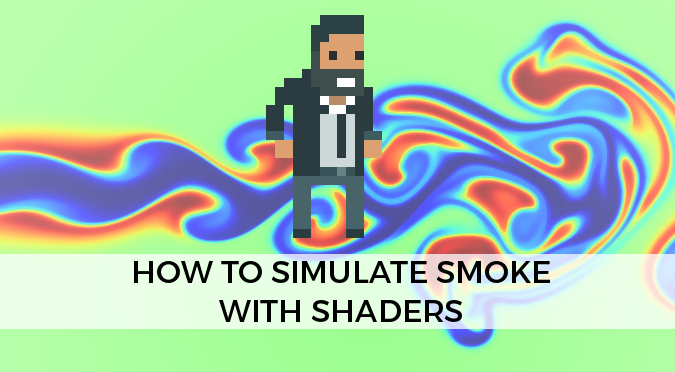
This tutorial will teach you how to simulate realistic smoke in Unity, using only shaders. Full code and a detailed explanations are provided.
does anyone know of a wireframe shader graph that actually traces the vertices instead of being a faked texture one? im looking for something that mimics unity's wireframe mode in the scenes draw mode dropdown.....but cant seem to find a tutorial that uses shadergraph and doesnt use another texture...
plus the tutorials all seem VERY old....
I'm trying to make a shader graph but my gradient property is locked at an unexposed state

Gradients do not exist as properties outside of SG, because the shader language does not recognize them
@patent yoke you can use a custom editor to create a gradient field, then convert it to a texture and sample that in your graph instead of sampling a gradient
i think setting the gradient in code would be easier, but I can't find a function for it
Yeah I'm pretty sure that is not possible :/
oh alright, i'll just convert the gradient to a texture
Finally managed to create a wireframe shader. Was weirdly hard considering it seems like the most basic one possible.

nice!
this guy asked for one, maybe you can help
I realised, I'm generating the mesh, so I can hide a bit of extra data in there. In this case, baryocentric coordinates in the color data for each vertex.
The way I did it required adding data to the mesh itself. You could do a monobehaviour that took in a mesh, added this data and then set the modified mesh into the MeshFilter. Then the shader can use that data to get a number for "how close to an edge am I".
Yep, it "sounds" easy to do, but once you undersand how shaders actually work, it's not obvious at all to do it for any arbitrary mesh.
Why do you keep telling them to use a custom editor? It's just another roadblock to them....
Curious. Just ask'n.
I'm not telling them to do anything, I'm just offering them an option for if they want to expose a gradient field


Is the tiling parameter 0 on one axis ?
its 1, 1
The Position node gives you a Vector3 (3D) coordinate and putting it into the Vector2 is only taking the x and y axis. For a flat plane you'd want X and Z instead
Can use the Split node on it and put the axis you want into Vector2/Combine node
^yep, that it's. I overlooked this node but was going to say that.
You guys think fiverr has shader experts that I can pay to fix this one god damn issue xD
I have a sprite of an object that needs to be colored completely. How can this be done?
I do not know how to make shaders, so I am dealing with such an easy target
thanks.
Hello, I'm learning shaders programming at this point I'm in a practice that shows how zbuffer works, I've a shader that have two render passes, Is there any reason why the second render pass is ignored, in my code it is supposed that first pass is ignored and second pass is displayed, but only the first pass is displayed. I don't know if I need to do anything else, no error codes in the console.
Here is the code 🙂 https://pastebin.com/1pDcXSAp thanks
Pastebin
Pastebin.com is the number one paste tool since 2002. Pastebin is a website where you can store text online for a set period of time.

I'm currently working on a blit material feature for URP and I can usually reference _MainTex in shader graph to get the camera's rendered texture, but I've run into a case where _MainTex is just blank. What could cause that to happen?
@signal flume can you share some code?
Sorry, I ended up figuring it out in the end. I just had it blit to a temporary render texture, send that to the blit material and then write it to the destination
Ah right! Glad you got it working
why is that game view still shows a black screen, even though ive stretched RawImage to fill the screen, and have applied the render texture to RawImage and the camera?
Is there a way to disable normal maps at a particular LOD level? Like at LOD3 since it's so far away from the camera, how do I disable normal maps just for LOD3 but keep them for LOD0/1/2
How would someone go about implementing lights like these?

Date of Recording: 2021-01-30
Bit more work on lighting this week, including a sneak peek at the in-engine components. A quick and dirty light volume shader uses the existing depthnormals pass I'm rendering to compute some pixel-art appropriate approximation of deferred lighting without having to re-render any geometry the way Unity's default f...
From what understand, its done using the depthnormal texture to calculate the lighting, but how are the halos and edge highlighting done?
In addition, I understand its implemented as a vertex/frag shader, but how does the shader only affect objects in a certin radius? Is is done using stencil buffers?
It's not, it doesn't use standard particle lights, its a custom implementation of point lights in a forward renderer, but using techniques similar to deferred light rendering
Simply using particle lights doesn't give you banded cel lighting or the edge detection shown in the demo
This guys whole rendering is custom, took him months to do. He basicly has a custom srp at this point. Best way to figure it out is to try and contact him
The halo just looks like a billboarded quad. The edge highlighting is done with depth normals too. That's actually likely the main reason why they have a depth normals pass in the first place. It's a similar idea to this : https://roystan.net/articles/outline-shader.html
As for the lights, I would assume they might be reconstructing the world position from the depth to compare with the center point of the sphere (cull front, ztest always) to get the point light attenuation. (or maybe all the lights are in an image effect, and light positions & radius are passed into an float4 array/buffer). Since it's using similar techniques to deferred maybe looking up how that works would give some further hints.
Hmmm I think I understand the general ideas behind the tech. Thank you, I'll try to implement this asap.
can anyone help me make a realistic water shader, ive been trying to make one for a week now and I'm not getting the result that I want
Could you post screenshots of your shadergraph? I would like to do the same thing but with squares instead of triangles. 👀
ok let me find the most basic one, I've been messing around a lot
ok the shader:

the "get wireframe" sub:

and then this relies on the "color" for each vertex containing barycentric coordinates. I just made sure each triangle was made from a red, a green and a blue vertex.
What is WireEdge and WireEdge2?
Is it defining the size of the displayed wireframe?
I guess I can also find it out myself. Anyway, thanks a lot!
So to get squares instead of triangles I would have to change the sub
doing squares would be complex
it looks like he's encoding positional data from the triangle
into the vertex color field
you would need to do something similar, but for the quads you wish to highlight
What does vertex color actually do exactly?
The Vertex Color Node documentation is not very specific
It accesses the colours stored in the vertices of the mesh data. jumble is storing the barycentric coordinates of each triangle there.
Would basically be (1,0,0), (0,1,0) and (0,0,1) for each vertex in a triangle. I guess the vertices might also not be shared between neighbouring triangles with that setup.
space depending on your mesh, you can create custom vertex attributes as well
color is one that's common
but you could define your own format
and stick whatever info you want on each vertex
doing these things will most likely require runtime manipulation/creation of the data
not as easy as just dropping a mesh in
What I would want is something that can draw these triangles or squares on any mesh (of a simple object like a cube or sphere)
Is there a way of doing this that does not require custom vertex attributes as long as the mesh is detailed enough?
If I'm using the Time node to do animation, what can I do to slow it down?
Yeah that's right, 3 vertices per triangle, noy shared (so I can set the normals for a whole triangle)
there's a reason that this asset doesn't already exist
Unfortunately
huh, I'm actually using Sine Time, this won't work here

ah, just split the sine out to a separate node
You'd need to use the Time output instead, do the Mutiply then put it through the Sine node
yep, thanks!
So your shader can only be applied to specific objects you modified to work with the shader?
Can I see the object in your 3D modelling software?
I don't know how to manipulate the meshes correctly, I have never done something like this before 😅 .
Yeah that's right. It's just C# code that generates the mesh, it's a geodesic sphere.
Would you be willing to share that code as well?
In my skybox, I want the noise to be visible +x and -x, so I figured, get the x of the normal vector, abs() it and then use that as T for a lerp. It looks right in the preview, but in the scene view the noise just never shows up. Whether I use Object or World in the Normal Vecotr node, the result is the same. What am I missing?

It's quite a lot of code files, not very well organised, but I can try to get it up into GitHub tomorrow - no objection to sharing it.
Not even sure if the skybox mesh has normals data. You could use the Position instead though.
yep, that's done it, thanks!
How do you actually port materials from blender to unity? Like is there a good written guide somewhere? From what I understand I can't just port materials straight over because the systems for materials are different in blender and unity but I gather that you're supposed to bake the materials to textures. Where I'm getting lost is how do I then add those textures in unity? Should I be using materials with textures on or just rendering the texture normally? For when I'm using solid colours I'm just importing the model from blender with materials then swapping out the nulled materials with ones I've created in unity but I feel like I've got this all wrong and could really do with a guide or some advice 🙂
So I was hoping someone could point me in the right direction. I am just a hobby creator and I recently made grass in my project. I don't know what kind of issue im having but I cant figure out what or how to fix that circular shine on the grass I made that appears as a sphere around where the camera view is. Basically I just don't know what it is or what I need to do to fix it lol. I think its a shader issue but honestly I don't even know, anyone got a clue?

well, once you’ve added a unity material, you can drop your baked texture in the box next to the inputs
example: normal map, albedo, occlusion map, roughness, etc
Hi all! I'm very new to shaders and I've made one with help from a tutorial that simply animates a background. The problem is it seems to break RectMask2D and when I look up how to implement Clipping via the comment here https://forum.unity.com/threads/rectmask2d-shader-requirements.496333/ I can't get it work. I would really appreciate if someone more knowledgable could weigh in if this is the best way to make RectMask2D work with my custom shader/explain what the most important parts of their script is to make that work! Thank you
EDIT: figured it out myself
I don't think so. Not sure it is specifically related to shadergraph, but a classical of transparent objects sorting
Can you share screenshots of : rendering with default lit / with shadergraph + shadergraph/material setup ?
Hello all, is it possible to use an Image shader to render only my gameObjects and make the background black for example?
@grand jolt in URP I use 'drawrenderers' for this
I think maybe 'replacement shaders' is something that will work for built in?
Thank you @devout quarry , you are talking about this? https://docs.unity3d.com/Manual/SL-ShaderReplacement.html
Yup but I have no experience with it so not sure if that's the best way in built in
In this video it is used to render objects with a certain shader to a buffer (and then use it further for outlines but that's not the point)

Support me on Patreon ➜ https://www.patreon.com/DanMoran
Follow me on the Twittersphere ➜ https://twitter.com/DanielJMoran
Get the Assets for this Video here ➜ https://goo.gl/LJQRFl
Oooh i get what you mean.
If you were to use URP what you would do is have a custom pass that calls DrawRenderers and then you can either filter by shadertag or by renderinglayer to decide what gets drawn. Good luck!
Thank you for the help! really appreciated. I'll try a bit to archieve this, I'm not too able with shader but the render with black background shown in the video should be enough.
whatdoes this mean
i googled it and got literally nothing
im trying to convert my shadergraphs to normal shaders for performance
looks like a missing semicolon or comma on line 54
its there
could just be another random thing, shader errors aren't very descriptive sometimes
How do I create a shader for my water mesh that allows for change in opacity so my water has a slight see through effect? I am just using a basic solid color shader to show the water's blue color. I messed around with the alpha settings in shader graph and it didn't change anything. How do I make my water have slight opacity?
idk what i did but i fixed it
can't believe I was away for a week and missed all the 3d->pixelart shenanigans 😦
don't worry, you'll get another chance when someone else inevitably comes asking about it again 😆
Hey I didnt wanna repost or anything, but does anyone by any chance have a idea to my problem about 20 messages up?
It looks like a LOD thing - are you using the terrain detail system to place the grass?
Well, I was using terrain trees to place it. I did do process of elimination and see it has something to do with the tree placer, just not sure why.
I'm afraid I'm entirely unfamiliar with Unity's terrain 😦 did you try the #⛰️┃terrain-3d channel aswell?
No I was thinking it was a shader issue but I just recently realized it must be a mixture of both, ill move over there. Thanks
Ok - i'm missing osmething obvious here. Using URP and trying to make a dead simple unlit sprite shader. Why is it pink? In the preview and in the game?

wait what the heck - could've sworn I made this project URP but somehow my render pipeline asset was null
false alarm
Ok better question. I have this script:
https://paste.myst.rs/ngty65yu
And the inspector looks like this:

Why is this not changing the "HueOffset" parameter at runtime?
If I manually change it from the inspector for the shader - it works. But the script doesn't seem to be capable of changing the parameter 🤔
Did you check that property variable name is the same?
Doesn't seem to work with the string form or the "property id" form
I believe it is. YOu can see the property name in the screenshot
vars have two names in ShaderGraph

I'm trying to replicate this effect. I can make a stepped toon shader but not sure how to create the transitioning dithers

yeah this is more or less what I did. got the idea from @teal breach actually.
why cant i find PBR graph in URP
The Lit graph is PBR
but when i make a material of the shader it doesnt work

see ?
have you saved the asset?
yup
can you do it again, because there's a * on the window
oh wait it saved when i closed it , i thought ctrl + s is enough to save lol
thanks its working now lol
you need to click the button
Make an N×N array of thresholds which defines the dither pattern. Use some spatial coordinate (either uv or screen) to determine the index you want, eg index = x % n + x * ( y % n ). Your source color lies a fraction f between two colours in the palette. Return color 1 if f > threshold, otherwise color 2
If you look at the wikipedia page for ordered dithering you may find it useful
If you have a 1-bit palette you can easily find f by taking eg the colours brightness. For more colors you will almost certainly need to use a look up table which is generated beforehand
There's some info on the LUT approach in the comments here https://mobile.twitter.com/drbentine/status/1366055216861298694
After seeing some images from @MrmoTarius that used ordered dithering, I spent some time this weekend seeing how it looks. https://t.co/iCRA9Nc4AZ
Is there a way to convert a URP shader to a standard pipeline shader at all?
Not automatically
Isn't there an option in the Assets menu somewhere at the bottom, with the option to convert all or selected materials to and from URP/HDRP/SRP ?
I was responding to @exotic pilot , I'm usually working on SRP so I couldn't check, thanks for the heads-up! 😄
No worries hehe
You can convert materials between pipelines, but that is just matching them to their closest equivalent shader in the other pipeline (and filling in the properties). But you can't automatically convert a shader between pipelines
I have this urp shader that is glitching because of casting shadows on self. I assume this is a common problem, so anyone knows how to fix it?
you can see what I'm talking about in the bottom of the sphere or the sides of the cube
`Varyings vertShadowCaster(Attributes input)
{
Varyings output;
VertexPositionInputs positionInput = GetVertexPositionInputs(input.positionOS.xyz);
VertexNormalInputs normalInput = GetVertexNormalInputs(input.normalOS);
output.positionCS = TransformWorldToHClip(ApplyShadowBias(positionInput.positionWS, normalInput.normalWS, _MainLightPosition.xyz));
#if UNITY_REVERSED_Z
output.positionCS.z = min(output.positionCS.z, output.positionCS.w * UNITY_NEAR_CLIP_VALUE);
#else
positionCS.z = max(positionCS.z, positionCS.w * UNITY_NEAR_CLIP_VALUE);
#endif // UNITY_REVERSED_Z
output.normalWS = normalInput.normalWS;
output.uv = TRANSFORM_TEX(input.texcoord, _BaseMap);
output.positionWSAndFogFactor.xyz = positionInput.positionWS;
output.positionWSAndFogFactor.w = ComputeFogFactor(positionInput.positionCS.z);
return output;
} // Function vert`
Looks like you have a bad case of shadow acne - see the Shadow Acne section of here: https://catlikecoding.com/unity/tutorials/rendering/part-7/
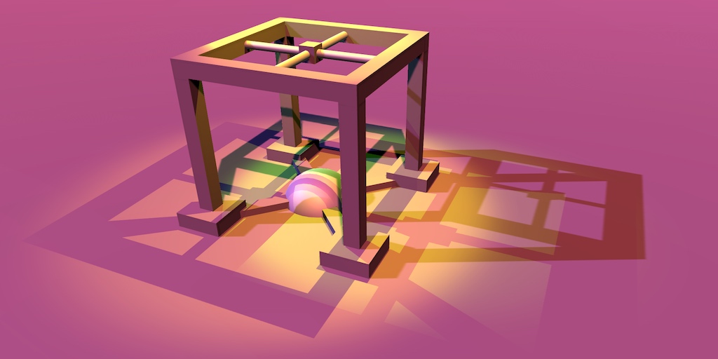
A Unity Rendering tutorial about supporting shadows. Part 7 of 20.
also possibly low resolution shadow map?
Hi guys 🙂 Is there a way to create an Unlit shader that receives shadow? Or in other words, is there a way to make a lit shader look unlit, but still receive the shadow information from light?
doesn't unlit means "no light"? Which means you can't get information from light sources?
Yeah, that's why I'm asking, if there is some kind of way to get around that somehow. For example modifying the lit shader to look unlit somehow. Basically ignoring lighting information except the shadow part.
Does that still work for dynamic shadows?
Hm... can you still tell me about it? Project may switch to URP soon anyway.
How would I go about that? I am very new to lighting and shadow, so lots of question marks.
I have only used it in shadergraph in URP. This is an updated repo of how it can be done.

GitHub
Some custom lighting functions/sub-graphs for Shader Graph, Universal Render Pipeline - Cyanilux/URP_ShaderGraphCustomLighting
This blog used to be a good resource but it seems only the cached version remains: https://webcache.googleusercontent.com/search?q=cache:5U-C3_rLAp4J:https://blog.unity.com/technology/custom-lighting-in-shader-graph-expanding-your-graphs-in-2019+&cd=1&hl=en&ct=clnk&gl=uk&client=firefox-b-e
Specifically, take a look at the custom functions because that's what you would use in your handwritten shader.
@teal breach yeah because it's outdated sadly, the cyanilux repo is much better now
Thanks @regal stag for the resources 🙂
I'm actually aware of cyans repo from another lighting issue I had. Guess I will take another look haha. Thanks guys!
@devout quarry can you maybe give me a brief rundown of what you are doing? Just roughly so I have somewhat of an idea.
What is the best way to reconstruct world space positions from a depth texture per object? Most of the information i've found online is for image effects or post processing, but I would like to retrieve world space positions from a mesh shader.
I've got this, though it's written more for Shader Graph / HLSL in URP : https://www.cyanilux.com/tutorials/depth/#reconstruct-world-pos (includes mesh perspective, orthographic and image effect versions). Should be the same idea for the built-in RP if that's what you're using, but the functions will be different.
I'll try this out, thanks
the beta 2021.2 has built in renderer support for shadergraph
Hello y'all, I asked a question yesterday and Alex answered with a good video but i can't get that solution work. Basically I need to take a screenshot of a GameObject without the skybox, so only the object with a neutral background like black or transparent. I'm pretty stuck and can't figure out a way to do so. Can someone help? Do i need a shader or is there a simpler way?
I wanted to subtract the col of a camera that rendered the object to one that doesn't see it but thinking about it seems a bad idea to me.
Are you using the capture method of unity or are you getting pixels with alpha?
Pixels with Alpha
If I use a shader for the background and another one for Geometry could it work?
Like the background return a white image
and the other one col
As long as your background writes into depth, it will be in the output, you might need to deactivate the background or exclude it somehow from depth texture and save a screenshot
Thank you very much. I'm able to take a depth map screenshot do you have any suggestion on how to use this information to exclude the background and highlight only the background?
You should be able to use the depth map alpha values to overwrite the texture2d alpha ones
You could also just make a camera copying the values of your main one and use that without background layer to take a screenshot as png
Sorry but what do you mean with without background layer?
if you set the camera to depth only, it will not render skybox for example, so you just have a transparent camera to take a screenshot with the simple capture built in unity function
Gonna try this little quick. Thank you so much and Sorry for the dumbish questions
I made a clipping mask to hide the Unity terrain under my roads. But now I need to hide these gaps between the road and the terrain. How should I proceed ? (roads are procedural)

are you talking about the greyish stuff?
that forms little blocks
yes
well where is that coming from?
what is the grey stuff
is that part of the road mesh or something?
I generate this texture (red line is where I have a road) then I use this texture in the terrain shader and I discard these pixels


line 87
it is not part of the road mesh, it is a hole in the terrain
as in those are pixels that are supposed to be part of the road
but they don't render
because they aren't actually part of the road
Is there a way of solving the problem of 'Compiler timed out. This can happen with extremely complex shaders or when the processing resources are limited.'
it seems the clipping mask is not precise enough
so do you render the road separately?
or does that shader actually render the road too
Yes the road is a separate gameobject
personally I would make the roads have some thickness
and raise them off the terrain a tad
so the terrain can render normally
either that or come up with a more precise way to define your road
some sort of datastructure that can be put into a ComputeBuffer
that you can look up a world pos to determine if it's part of a road with
I want the road to be slightly under the terrain level, like this :

if you added that dirtlike border to your road
you could probably fill in all the holes
what resolution texture are you using
for the clipping mask
is there a way to do that without adding new geometry ?
512*512
I would definitely bump that resolution up
to 1024x1024
you may have to add an extra quad to the exterior of the road
I don't think it would solve the issue, it would just make the hole smaller
yes but it would shrink how big your border needs to be
rn you would need a pretty large border
might look wierd
Have you considered using parallax mapping instead of embedding the road in the terrain?
but also this approach is gonna be odd for physics
since the terrain is still there
is your plan to have wheels look like they are floating off the ground?
I have no idea what parallax mapping is 🤔
I don't see how faking depth could hide the gaps 🤔
I don't think I will need physics in my game ; it's a city builder
vehicles are following some bezier curves on roads
I mean
your roads will have sidewalks and stuff
things built near them
just offset them a tad above the terrain
and you don't have to do any of this work
and in the top-down perspective it will be hardly noticeable
the difference between these approaches
I did that before, but it causes other issues. When the terrain is not flat, sometimes the terrain goes above the road. Also I want to be able to paint a pavement texture on the terrain around buildings and this pavement texture should be seamlessly connected to the sidewalk, like this :

A bit late to the party, but you can also set the backdrop color alpha to 0
if I were doing this I probably wouldn't use a unity terrain
I would just generate the meshes for these things
exactly the way they needed to be
That's not what they did there :

who is they
derekt - you may want to look into stencil buffers
is that screenshot what you want to do?
because they are just doing exactly what I suggested
which is a raised road
with a border
and then what you need to do
is flatten the terrain around placed objects
it's Cities : Skylines. The mesh wireframe is visible thanks to Intel GPA